WO2014003039A1 - Intraocular lens - Google Patents
Intraocular lens Download PDFInfo
- Publication number
- WO2014003039A1 WO2014003039A1 PCT/JP2013/067458 JP2013067458W WO2014003039A1 WO 2014003039 A1 WO2014003039 A1 WO 2014003039A1 JP 2013067458 W JP2013067458 W JP 2013067458W WO 2014003039 A1 WO2014003039 A1 WO 2014003039A1
- Authority
- WO
- WIPO (PCT)
- Prior art keywords
- intraocular lens
- optical
- flexible
- lens
- capsule
- Prior art date
Links
Images


Classifications
-
- A—HUMAN NECESSITIES
- A61—MEDICAL OR VETERINARY SCIENCE; HYGIENE
- A61F—FILTERS IMPLANTABLE INTO BLOOD VESSELS; PROSTHESES; DEVICES PROVIDING PATENCY TO, OR PREVENTING COLLAPSING OF, TUBULAR STRUCTURES OF THE BODY, e.g. STENTS; ORTHOPAEDIC, NURSING OR CONTRACEPTIVE DEVICES; FOMENTATION; TREATMENT OR PROTECTION OF EYES OR EARS; BANDAGES, DRESSINGS OR ABSORBENT PADS; FIRST-AID KITS
- A61F2/00—Filters implantable into blood vessels; Prostheses, i.e. artificial substitutes or replacements for parts of the body; Appliances for connecting them with the body; Devices providing patency to, or preventing collapsing of, tubular structures of the body, e.g. stents
- A61F2/02—Prostheses implantable into the body
- A61F2/14—Eye parts, e.g. lenses, corneal implants; Implanting instruments specially adapted therefor; Artificial eyes
- A61F2/16—Intraocular lenses
- A61F2/1613—Intraocular lenses having special lens configurations, e.g. multipart lenses; having particular optical properties, e.g. pseudo-accommodative lenses, lenses having aberration corrections, diffractive lenses, lenses for variably absorbing electromagnetic radiation, lenses having variable focus
- A61F2/1624—Intraocular lenses having special lens configurations, e.g. multipart lenses; having particular optical properties, e.g. pseudo-accommodative lenses, lenses having aberration corrections, diffractive lenses, lenses for variably absorbing electromagnetic radiation, lenses having variable focus having adjustable focus; power activated variable focus means, e.g. mechanically or electrically by the ciliary muscle or from the outside
- A61F2/1635—Intraocular lenses having special lens configurations, e.g. multipart lenses; having particular optical properties, e.g. pseudo-accommodative lenses, lenses having aberration corrections, diffractive lenses, lenses for variably absorbing electromagnetic radiation, lenses having variable focus having adjustable focus; power activated variable focus means, e.g. mechanically or electrically by the ciliary muscle or from the outside for changing shape
-
- A—HUMAN NECESSITIES
- A61—MEDICAL OR VETERINARY SCIENCE; HYGIENE
- A61F—FILTERS IMPLANTABLE INTO BLOOD VESSELS; PROSTHESES; DEVICES PROVIDING PATENCY TO, OR PREVENTING COLLAPSING OF, TUBULAR STRUCTURES OF THE BODY, e.g. STENTS; ORTHOPAEDIC, NURSING OR CONTRACEPTIVE DEVICES; FOMENTATION; TREATMENT OR PROTECTION OF EYES OR EARS; BANDAGES, DRESSINGS OR ABSORBENT PADS; FIRST-AID KITS
- A61F2/00—Filters implantable into blood vessels; Prostheses, i.e. artificial substitutes or replacements for parts of the body; Appliances for connecting them with the body; Devices providing patency to, or preventing collapsing of, tubular structures of the body, e.g. stents
- A61F2/02—Prostheses implantable into the body
- A61F2/14—Eye parts, e.g. lenses, corneal implants; Implanting instruments specially adapted therefor; Artificial eyes
- A61F2/16—Intraocular lenses
- A61F2002/1681—Intraocular lenses having supporting structure for lens, e.g. haptics
- A61F2002/16901—Supporting structure conforms to shape of capsular bag
Definitions
- the present invention relates to an intraocular lens that is inserted into the eye as an alternative function of the crystalline lens.
- An intraocular lens used for treatment is composed of an optical part that functions as a lens and a support part that supports the optical part.
- intraocular lenses that can be inserted through small incisions, specifically intraocular lenses having an optical part made of a soft material, have become mainstream.
- the optical part is made of a soft material, so that the optical part can be bent and inserted from a small incision.
- one-piece type intraocular lenses in which the support portion and the optical portion are made of the same material are becoming widespread for the purpose of easy insertion into the eye and strengthening of the connection portion between the support portion and the optical portion.
- One of the important factors in considering an intraocular lens is to stably hold the intraocular lens in the eye (in the lens capsule).
- the intraocular lens is deviated or tilted from the center of the crystalline lens capsule during or after the operation, the target visual acuity cannot be obtained.
- the lens in which the optical unit can be folded, if the lens is held in an unstable state in the lens capsule, the lens itself may be deformed. For this reason, it is important to stably hold the intraocular lens in the lens capsule.
- techniques described in Patent Documents 1 to 3 are known as techniques aiming to stably hold the intraocular lens in the lens capsule.
- a technique described in Patent Document 4 is known as a technique relating to the position and displacement of the intraocular lens within the lens capsule.
- the capsular bag contracts after the operation. At this time, an inward force is applied to the support portion of the intraocular lens. Furthermore, when the capsular bag contracts over time after the operation, the posterior bag of the capsular bag comes into contact with the optical part of the intraocular lens. Conventionally, when an inward force is applied to the support portion due to contraction of the lens capsule after insertion of the intraocular lens, the optical portion may move forward and come into contact with the iris. If the optical part of the intraocular lens comes into contact with the iris, it may cause inflammation.
- the support part is obliquely bent with respect to the optical part, thereby bringing the optical part closer to the posterior capsule side (the side away from the iris).
- the structure of a mold used for manufacturing an intraocular lens (such as a cast mold manufacturing method) is compared with a configuration in which the support portion is formed in parallel with the optical portion. Inconveniences such as complicated and (b) the process of cutting out the intraocular lens from the molded lens substrate become troublesome.
- the cross-sectional shape of the support portion in contact with the equator portion of the crystalline lens capsule is set to a triangle or the like.
- the inclined part of the support part 53 having a triangular cross-section supporting the optical part 52 of the intraocular lens 51 is a crystalline lens. It follows the shape of the anterior capsule side of the sac 54. For this reason, when the optical part 52 and the support part 53 are formed flat, the optical part 52 is disposed at a position closer to the front side Fs than the equator of the lens capsule 54 (indicated by a dashed line in the figure).
- Patent Document 4 also describes a configuration in which the support portion of the intraocular lens has a two-layer structure of a hard material and a soft material.
- the support part is made to conform to the shape of the anterior capsule side, and inward force due to contraction of the lens capsule is received obliquely by the support part.
- this configuration is adopted, the manufacturing of the intraocular lens is complicated as compared with the above-described one-piece type, which causes a significant cost increase.
- the main object of the present invention is to provide a technique capable of making it difficult for the intraocular lens to come into contact with the iris and suppressing the tilt of the intraocular lens in the lens capsule.
- the first aspect of the present invention is: An optical part having two optical surfaces; and a support part formed in a state of extending outward from an outer peripheral part of the optical part to support the optical part, and one optical surface of the optical part is An intraocular lens that is used in the lens capsule of the eyeball so that the front and other optical surfaces face the back,
- the support portion is disposed along the equatorial portion of the lens capsule when inserted into the lens capsule, and has a flexible portion that elastically deforms by receiving an inward force due to contraction of the lens capsule,
- the rear side of the outer surface of the flexible part in contact with the equator portion in the lens capsule is formed in an inclined state or a notched state so as to follow the shape of the posterior capsule side of the lens capsule. It is an intraocular lens.
- the second aspect of the present invention is:
- the cross-sectional shape of the flexible part in contact with the equator part is such that the optical part moves to the rear side when the flexible part is elastically deformed by receiving the inward force.
- the third aspect of the present invention is:
- the cross-sectional shape of the flexible portion in contact with the equator portion has two main shapes in which the central position when the flexible portion receives the inward force in the thickness direction of the support portion defines the thickness of the support portion. It is the shape located in the said front side rather than the center position between surfaces. It is an intraocular lens as described in the said 1st or 2nd aspect characterized by the above-mentioned.
- the fourth aspect of the present invention is:
- the cross-sectional shape of the flexible part in contact with the equator part is such that when the inward force is applied to the flexible part, the inward force with respect to the flexible part is more forward than the rear side.
- the intraocular lens according to any one of the first to third aspects, wherein the intraocular lens has an asymmetric shape so as to act strongly on the eye.
- the cross-sectional shape of the flexible portion includes an inclined surface formed in a state where a part of the outer surface of the flexible portion is formed and a rear side of the outer surface is obliquely cut out.
- the intraocular lens according to any one of the first to fourth aspects.
- the sixth aspect of the present invention is: The intraocular lens according to any one of the first to fifth aspects, wherein the optical part and the support part are made of the same soft material.
- the seventh aspect of the present invention is The intraocular lens according to any one of the first to sixth aspects, wherein the support portion is formed in an open loop shape.
- the eighth aspect of the present invention is The intraocular lens according to any one of the first to seventh aspects, wherein a thickness dimension of the support portion is 0.3 mm or more.
- the intraocular lens can be made difficult to come into contact with the iris, and the inclination of the intraocular lens in the lens capsule can be suppressed.
- FIG. 1 It is a figure explaining the planar cross-section of an eyeball.
- the structure of the intraocular lens which concerns on embodiment of this invention is shown, (A) is a top view, (B) is a side view. It is an enlarged view which shows an example of the cross-sectional shape of the flexible part of the intraocular lens which concerns on embodiment of this invention. It is a figure explaining the installation state of an intraocular lens. It is a figure explaining the malfunction which may occur at the time of insertion of an intraocular lens, and the solution reason. It is an enlarged view (the 1) which shows the other example of the cross-sectional shape of a flexible part. It is an enlarged view (the 2) which shows the other example of the cross-sectional shape of a flexible part. It is an enlarged view (the 3) which shows the other example of the cross-sectional shape of a flexible part. It is the figure which compared the support state of the intraocular lens in a lens capsule.
- FIG. 1 is a diagram illustrating a planar cross-sectional structure of an eyeball.
- the eyeball 1 has a spherical shape as a whole and is covered and protected by the sclera 3 except for the front cornea 2.
- the surface of the sclera 3 around the cornea 2 is covered with a conjunctiva 4.
- the cornea 2 functions not only as an eyeball protection function but also as a lens that refracts incoming light.
- On the inner side (back side) of the cornea 2 is an anterior chamber 5 filled with aqueous humor, and a pupil 7 is located in the center of the iris 6 facing the anterior chamber 5.
- the iris 6 functions to adjust the amount of light incident on the inside of the eyeball 1 by adjusting the size of the pupil 7 (the size of the opening).
- the front surface of the crystalline lens 8 faces the pupil 7.
- the crystalline lens 8 has a shape like a convex lens and functions to adjust the focal point.
- the crystalline lens 8 is encased in a crystalline lens capsule made of a transparent thin film.
- a ciliary body 10 is connected to the crystalline lens 8 via a ciliary band 9.
- the ciliary body 10 is a tissue that performs focusing by controlling the thickness of the crystalline lens 8.
- the vitreous body 11 occupies most of the inside of the eyeball 1.
- the vitreous body 11 is a jelly-like colorless and transparent tissue, and maintains the shape and elasticity of the eyeball 1.
- the vitreous body 11 transmits the light refracted by the crystalline lens 8 to the retina 13.
- the retina 13 is a membrane tissue located on the innermost side in the eyeball 1. In the retina 13, there are photoreceptor cells that sense light incident into the eyeball 1 through the pupil 7 and identify its intensity, color, shape, and the like.
- the choroid 14 is a membrane tissue located inside the sclera 3 (that is, between the sclera 3 and the retina 13).
- the choroid 14 is rich in blood vessels, and also serves as a blood flow path to each tissue of the eyeball 1 to give nutrition to the eyeball 1.
- an optic nerve 15 is connected to the back side (back side) of the eyeball 1.
- the optic nerve 15 is a nerve that transmits light stimulation received by the retina 13 to the brain.
- a blind spot 16 is present at a portion where the optic nerve 15 is connected.
- the blind spot 16 is located 4 to 5 mm away from the fovea 17.
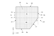
- Configuration of intraocular lens> 2A and 2B show a configuration of an intraocular lens according to an embodiment of the present invention, where FIG. 2A is a plan view and FIG. 2B is a side view.
- the intraocular lens 21 includes an optical unit 22 that performs an optical lens function and a pair of support units 23 that support the optical unit 22.
- the optical part 22 and the support part 23 have an integrated structure.
- the intraocular lens 21 including the optical part 22 and the support part 23 is formed flat as a whole. In other words, the optical unit 22 and the support unit 23 are formed in parallel with each other with respect to a virtual plane orthogonal to the optical axis of the intraocular lens 21.
- the optical unit 22 is formed in a convex lens shape having a circular shape in plan view.
- the optical unit 22 has two optical surfaces 22a and 22b.
- the one optical surface 22a is disposed so as to face the front side Fs, and the other optical surface 22b faces the back side Rs.
- the “front side Fs” described here corresponds to the outside of the eyeball when the intraocular lens 21 is housed in the crystalline lens capsule of the eyeball, and the “rear side Rs” corresponds to the center side of the eyeball.
- one optical surface 22a is arranged facing the anterior capsule side
- the other optical surface 22b is arranged facing the posterior capsule side.
- the “front side Fs” and “rear side Rs” of the intraocular lens 21 can be identified by the difference in curvature radius between the optical surfaces 22a and 22b.
- the diameter D of the optical unit 22 may be set to any size as long as it is a size suitable for inserting the intraocular lens 21 into the intraocular lens capsule.
- the diameter D of the optical unit 22 is preferably set in the range of 5 mm to 7 mm, more preferably 6 mm. What is necessary is just to set the thickness of the optical part 22 according to a desired refractive index.
- the optical unit 22 is made of a soft material having light transmittance. Specifically, the optical unit 22 is made of a soft material such as a silicone resin, an acrylic resin, a hydrogel, or a urethane resin. Thereby, the optical part 22 can be folded.
- the term “foldable” described here is used to mean that the intraocular lens 21 including the lens portion 22 can be folded at least in half.
- the support part 23 is formed in a state extending outward from the outer peripheral part of the optical part 22.
- the support part 23 is a part that supports the optical part 22 when the intraocular lens 21 is inserted into the eye.
- Two support portions 23 are formed on one intraocular lens 21.
- Each support portion 23 draws an arc in a counterclockwise direction in the drawing from a portion where an axis passing through the center C of the optical portion 22 (indicated by a one-dot chain line in the figure) intersects the outer peripheral portion of the optical portion 22. It extends to.
- the support part 23 has the base part 24 and the flexible part 25 integrally.
- the base portion 24 is formed in a state adjacent to the outer peripheral portion of the optical unit 22 in the diameter direction of the optical unit 22. Further, the base portion 24 is formed in a mountain-like shape and is joined to the optical unit 22 at the widest portion.
- the flexible part 25 has moderate flexibility.
- the flexible portion 25 is curved so as to draw a smooth arc starting from the boundary with the base portion 24.
- the distal end portion of the support portion 23 serving as the extending end of the flexible portion 25 has a rounded shape (round shape).
- the flexible portion 25 is configured to be elastically deformable due to the flexibility of the flexible portion 25 itself.
- the flexible part 25 extends in a slender shape as a whole, and the material itself constituting the flexible part 25 has appropriate flexibility.
- the flexible portion 25 is integrally formed of the same soft material as that of the optical portion 22 together with the root portion 24 described above.
- the intraocular lens 21 corresponds to a one-piece type intraocular lens.
- the support portion 23 (mainly the flexible portion 25) can be elastically deformed by receiving this force. It has a configuration.
- the “inward force” described here refers to a force toward the center C side of the optical unit 22.
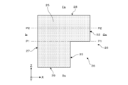
- FIG. 3 shows a cross-sectional shape when the flexible portion 25 is cross-sectioned at the QQ position in FIG. 2 (A), for example.
- the width direction of the support portion 23 is denoted as the X direction
- the length direction of the support portion 23 is denoted as the Y direction
- the thickness direction of the support portion 23 is denoted as the Z direction.
- the side surface positioned at the “outer side Os” is positioned at the outer side surface 26 and the “inner side Is”.
- the side surface to be used is the inner side surface 27.
- the “inside Is” described here refers to the side facing the optical unit 22, and the opposite side is referred to as “outside Os”.
- the “front Fs” main surface is the front main surface 28, and the “rear Rs” main surface is the rear main surface 29.
- the front main surface 28 and the rear main surface 29 are both parallel to a virtual plane orthogonal to the optical axis of the intraocular lens 21 (optical unit 22).
- the outer surface 26 of the flexible portion 25 is disposed so as to face the equator portion of the lens capsule (hereinafter also simply referred to as “equator portion”) when the intraocular lens 21 is normally housed in the lens capsule. .
- the flexible portion 25 is a portion that receives an inward force due to contraction of the lens capsule.
- the equator of the capsular bag is the boundary between the anterior and posterior capsules.
- the outer surface 26 of the flexible portion 25 is formed by an outer end surface 30 that forms a right angle with the front main surface 28, and an inclined surface 31 that has an angle ⁇ ( ⁇ > 0 degrees) with respect to the outer end surface 30. ing.
- the outer end surface 30 is formed on the front side Fs of the flexible portion 25, and the inclined surface 31 is the rear side of the flexible portion 25. Rs is formed.
- the outer end surface 30 is formed in a state parallel to the inner side surface 27, and the inclined surface 31 is a state in which the rear side Rs of the outer surface 26 is obliquely cut out so as to follow the shape of the posterior capsule side of the lens capsule.
- the inclination angle ⁇ of the inclined surface 31 is preferably set in the range of 30 to 50 degrees, more preferably in the range of 35 to 45 degrees, and still more preferably 40 degrees.
- the inclined surface 31 is continuously formed over substantially the entire length of the flexible portion 25 in the length direction Y of the support portion 23.
- the inclined surface 31 is continuously formed from the flexible portion 25 to a part of the root portion 24.
- the cross-sectional shape of the flexible portion 25 in the direction orthogonal to the length direction Y of the support portion 23 is as follows (1) to ( The shape corresponds to any of 3).
- the cross-sectional shape of the flexible portion 25 is such that the cross-sectional area S1 of the front side Fs is rearward so that the optical portion 22 moves to the rear side Rs when the flexible portion 25 is elastically deformed by receiving an inward force.
- the shape is larger than the cross-sectional area S2 of the side Rs.
- the cross-sectional area S1 of the front side Fs is the center when the cross-sectional shape of the flexible portion 25 is divided into two at the center position P1 between the two main surfaces 28 and 29 defining the thickness of the support portion 23.
- the area of the cross-sectional part located in front Fs rather than the position P1 is said.
- the cross-sectional area S2 on the rear side Rs refers to the area of the cross-sectional portion located on the rear side Rs from the center position P1.
- the boundary between the outer end surface 30 and the inclined surface 31 coincides with the center position P1.
- the cross-sectional shape of the flexible portion 25 is a shape in which the cross-sectional area S1 of the front side Fs is larger than the cross-sectional area S2 of the rear side Rs due to the presence of the notch portion by the inclined surface 31.
- the cross-sectional shape of the flexible portion 25 is such that the central position (hereinafter also referred to as “pressure center position”) P2 when the flexible portion 25 receives an inward force in the thickness direction Z of the support portion 23.
- the shape is located on the front side Fs with respect to the center position P1 between the two main surfaces 28 and 29 defining the thickness of the support portion 23. Further, the pressing center position P2 is shifted to the front side Fs by the ⁇ dimension from the center position P1.
- the ⁇ dimension is equivalent to 1 ⁇ 4 of the thickness dimension of the support portion 23.
- the dimensional relation is other than this. May be.
- the thickness direction Z of the support portion 23 for example, when the center portion of the outer end surface 30 is recessed, inward force is applied to both end portions of the outer end surface 30 across the recessed portion. Therefore, the pressing center position P2 does not change greatly depending on the presence or absence of the recessed portion.
- the cross-sectional shape of the flexible portion 25 is such that when the inward force described above is applied to the flexible portion 25, the inward force is applied to the flexible portion 25 on the front side Fs rather than the rear side Rs. It has an asymmetric shape to work strongly. More specifically, the cross-sectional shape of the flexible portion 25 is, for example, an asymmetric shape in the front-rear direction (up and down) when viewed with reference to a one-dot chain line indicating the center position P1 in FIG.
- an intraocular lens insertion device (not shown) with the intraocular lens 21 attached in advance into the eye through the mouth of the eyeball, and pushing the intraocular lens 21 out of the intraocular lens insertion device in that state, The intraocular lens 21 is inserted into the eye (in the lens capsule) through the wound.
- the intraocular lens 21 is folded into a small shape within the intraocular lens insertion device when the intraocular lens 21 is attached to the intraocular lens insertion device.
- the intraocular lens 21 inserted into the eye expands (restores) to its original shape as time passes.
- the position of the intraocular lens 21 accommodated in the lens capsule is inappropriate, the position of the intraocular lens 21 is adjusted using an instrument or the like.
- the flexible portion 25 of each support portion 23 extending from the optical portion 22 contacts the equator portion of the lens capsule 34 with an appropriate pressure, The optical unit 22 is supported using this contact pressure.
- the optical surface 22a of the optical unit 22 is disposed on the side facing the anterior capsule 34a, and the optical surface 22b is disposed on the side facing the posterior capsule 34b.
- the intraocular lens 21 according to the embodiment of the present invention, the following effects are obtained. That is, when the intraocular lens 21 is inserted into the capsular bag 34, since the inclined surface 31 is formed on the outer surface 26 of the flexible portion 25 of the support portion 23, the intraocular lens 21 is inclined or misaligned. It is installed in an appropriate position without having to. The reason is as follows.
- the inclined surface 31 is formed on the outer surface 26 of the flexible portion 25, the cross-sectional shape of the flexible portion 25 is equator due to the presence of the inclined surface 31, as shown in FIG. Therefore, the edge portion of the outer surface 26 of the flexible portion 25 is not easily caught by the equator portion of the lens capsule 34.
- the inclined surface 31 of the outer surface 26 of the flexible portion 25 is inclined so as to follow the shape of the capsular bag 34 and the sectional shape of the flexible portion 25 including the inclined surface 31 is The shape follows the shape of the equator. For this reason, the accommodation degree of the flexible part 25 with respect to the equator part of the crystalline lens capsule 34 becomes favorable.
- the inclination of the intraocular lens 21 can be suppressed and supported in a stable state.
- the intraocular lens 21 is stably supported, so that an effect of reducing the risk of occurrence of positional deviation or the like can be obtained.
- the same effect can be obtained by reducing the thickness dimension of the entire support part 23 including the flexible part 25.
- the thickness dimension of the support part 23 is reduced, the rigidity and strength required for the support part 23 to properly support the optical part 22 may not be ensured.
- the thickness dimension of the support part 23 two main surfaces
- the thickness dimension of the support part 23 is 0.3 mm or more, if the inclined surface 31 is formed on the outer surface 26 of the flexible part 25, the fit to the equator part is improved and the intraocular lens 21 is formed. Can be installed stably.
- the optical unit 52 is arranged at a position closer to the front side Fs than the equator (indicated by a one-dot chain line in the figure).
- the outer end surface 30 of the outer end surface 30 and the inclined surface 31 constituting the outer surface 26 of the flexible portion 25 is the equator of the lens capsule 34.
- the inclined surface 31 is arranged along the shape of the posterior capsule side of the crystalline lens capsule 34. For this reason, as shown in FIG.
- the optical unit 22 of the intraocular lens 21 is disposed at a position closer to the rear side Rs than the equator of the lens capsule 34 (indicated by the alternate long and short dash line in the figure). . Therefore, a larger space is secured on the anterior capsule side of the optical unit 22. Therefore, the risk that the optical unit 22 contacts the iris is reduced.
- the support portion 23 is formed of the same material, the cost can be significantly reduced compared to the case where this is a two-layer structure of different materials. Can do.
- the flexible portion 25 of the support portion 23 is elastically deformed by receiving inward force due to contraction of the lens capsule 34.
- the optical unit 22 is easily displaced to the rear side Rs.
- the reason is that by forming the inclined surface 31 on the outer surface 26 of the flexible portion 25, the inward force applied to the flexible portion 25 when the lens capsule 34 contracts is more on the front side Fs than on the rear side Rs. Because it works hard. This means that a stronger force acts on the outer end surface 30 than the inclined surface 31 among the outer end surface 30 and the inclined surface 31 constituting the outer surface 26 of the flexible portion 25.
- the outer end surface 30 in which the contact area of the main portion receiving the inward force among the outer surface 26 of the flexible portion 25 receiving the inward force due to the contraction of the lens capsule 34 is a part of the outer surface 26. Limited to For this reason, the force per unit area which the flexible part 25 receives by shrinkage
- the optical portion 22 is not necessarily displaced, and the amount by which the optical portion 22 is displaced toward the posterior capsule 34b is very small. It becomes. That is, in the embodiment of the present invention, the optical unit 22 is slightly displaced toward the posterior capsule 34b or easily displaced by the balance of the forces of the front side Fs and the rear side Rs acting on the flexible portion 25. This reduces the risk of the optical part 22 coming into contact with the iris. For this reason, when the intraocular lens 21 is inserted into the crystalline lens capsule 34, the amount of displacement of the optical part 22 with respect to the thickness direction Z of the support part 23 can be minimized. Therefore, as compared with an intraocular lens intended to move the optical unit 22 to the posterior capsule side in the lens capsule 34, variation in the installation position of the optical unit 22 in the optical axis direction can be reduced.
- Secondary cataract refers to a cataract that develops in months to years after surgery for inserting an intraocular lens.
- the main cause of the occurrence of secondary cataract is that lens epithelial cells proliferate between the optical unit 22 and the posterior capsule 34b to cause turbidity.
- the contact state between the optical unit 22 and the posterior capsule 34b is close, it is considered that the proliferation of the lens epithelial cells is suppressed and the risk of developing the subsequent cataract is reduced.
- the inclined surface 31 does not necessarily have to be formed over the entire length of the flexible portion 25.
- the inclined surface 31 is formed only in the portion that receives the force directly inward due to the contraction of the lens capsule 34, specifically, in the range where the flexible portion 25 directly contacts the equator portion of the lens capsule 34. May be.
- the portion forming the inclined surface 31 on the outer surface 26 of the flexible portion 25 is the entire contact area where the flexible portion 25 contacts the contracting lens capsule 34. Even when the inclined surface 31 is formed at a ratio of 50% or more and less than 100% of the contact area, the above-described effects can be exhibited.
- the cross-sectional shape of the flexible portion 25 in the direction orthogonal to the length direction Y of the support portion 23 is as shown in FIG. 3, but the present invention is not limited to this.
- the cross-sectional shape of the flexible portion 25 described above may be a shape as shown in FIG. 6, FIG. 7, or FIG.
- an outer surface 26 of the flexible portion 25 is constituted by an outer end surface 32 and a recessed surface 33 by forming a cutout portion 36 having an L-shaped cross section on the rear side Rs of the flexible portion 25. Yes.
- the outer end surface 32 is formed to make a right angle with the front main surface 28.
- the recessed surface 33 is formed in parallel with the outer end surface 32. Further, the recessed surface 33 is formed in a state of being recessed inward from the outer end surface 32 in the width direction X of the support portion 23.
- the cross-sectional shape of the flexible portion 25 includes a round-shaped outer surface 26 that bulges outward, and the top position P3 of the outer surface 26 is greater than the center position P1 between the two main surfaces 28 and 29. Is also in a shape located on the front side Fs.
- the top position P3 of the outer surface 26 refers to the position of the outermost Os in the width direction X of the support portion 23.
- the rear side Rs of the outer surface 26 is formed in an inclined state so as to follow the shape of the posterior capsule side of the crystalline lens capsule 34.
- the cross-sectional shape of the flexible portion 25 is a shape including an outer surface 26 that is obliquely curved from the outer end portion 28 a of the front main surface 28 toward the outer end portion 29 a of the rear main surface 29. .
- the rear side Rs of the outer surface 26 is formed in a curved and inclined state so as to follow the shape of the posterior capsule side of the crystalline lens capsule 34.
- the first shape example (FIG. 6), the second shape example (FIG. 7), and the third shape example (FIG. 8) described here are all of (1) to (3) described above. Corresponds to the shape.
- the intraocular lens 21 provided with the support part 23 of the open loop shape was illustrated, even if applied to the intraocular lens provided with the support part of a closed loop shape not only this but Good.
- the thickness dimension of the support part for obtaining a desired holding force is smaller than that of the intraocular lens having the support part having a closed loop shape. growing. For this reason, when this invention is applied to the intraocular lens 21 provided with the support part 23 of the open loop shape, a more remarkable effect is acquired at the point of installing the intraocular lens 21 stably.
- the optical part 22 and the support part 23 were comprised with the same material (soft material), it is not restricted to this,
- the optical part 22 is a soft material and the support part 23 is a hard material (for example, , Polymethyl methacrylate, etc.).
- the optical part 22 and the base part 24 may be made of a soft material, and the flexible part 25 may be made of a hard material.
Abstract
This intraocular lens is used held within the lens capsule of an eyeball, and is provided with: an optical section having two optical surfaces; and a support section that supports same. The support section is disposed in a manner so as to face the equator of the lens capsule when inserted therein, has a flexible section (25) that can elastically deform when incurring inward-facing force resulting from the contraction of the lens capsule, and, at the posterior side (Rs) of the outside surface (26) of the flexible section (25) contacting the equator within the lens capsule, is formed having an inclined surface (31) inclined in a manner so as to follow the shape at the posterior capsule side of the lens capsule.
Description
本発明は、水晶体の代替機能として眼内に挿入される眼内レンズに関する。
The present invention relates to an intraocular lens that is inserted into the eye as an alternative function of the crystalline lens.
高齢者人口の増加にともなって老人性白内障患者の増加が目立ってきている。白内障の治療法としては、眼球の内部に眼内レンズを挿入する方法、より具体的には、混濁した水晶体を摘出した後の水晶体嚢内に眼内レンズを挿入する方法が知られている。治療に用いられる眼内レンズは、レンズの機能を果たす光学部と、この光学部を支持する支持部とによって構成されている。
As the elderly population increases, the number of senile cataract patients is increasing. As a method for treating cataract, a method of inserting an intraocular lens into the inside of an eyeball, more specifically, a method of inserting an intraocular lens into a lens capsule after removing a cloudy lens is known. An intraocular lens used for treatment is composed of an optical part that functions as a lens and a support part that supports the optical part.
近年では、術後乱視や手術侵襲の軽減を目的として、小切開創から挿入可能な眼内レンズ、具体的には、軟質材料の光学部をもつ眼内レンズが主流になっている。この種の眼内レンズにおいては、光学部を軟質材料で構成することにより、光学部を折り曲げて小切開創からの挿入を可能にしている。さらに現在では、眼内への挿入容易性や、支持部と光学部の接続箇所の強化などを目的として、支持部と光学部を同一材料としたワンピースタイプの眼内レンズが広まりつつある。
In recent years, for the purpose of reducing postoperative astigmatism and surgical invasion, intraocular lenses that can be inserted through small incisions, specifically intraocular lenses having an optical part made of a soft material, have become mainstream. In this type of intraocular lens, the optical part is made of a soft material, so that the optical part can be bent and inserted from a small incision. Furthermore, at present, one-piece type intraocular lenses in which the support portion and the optical portion are made of the same material are becoming widespread for the purpose of easy insertion into the eye and strengthening of the connection portion between the support portion and the optical portion.
眼内レンズを考える上で重要な要素の一つとして、眼内レンズを眼内(水晶体嚢内)で安定的に保持することがあげられる。この点に関して、たとえば、手術時あるいは手術後に眼内レンズが水晶体嚢の中心からずれたり傾いたりすると、目的とする視力が得られなくなる。特に、光学部を折り畳み可能とした軟性眼内レンズの場合は、これが水晶体嚢内で不安定な状態で保持されると、レンズ自身が変形するおそれがある。このため、水晶体嚢内で眼内レンズを安定的に保持することが重要となる。ちなみに、水晶体嚢内で眼内レンズを安定的に保持することを目的とした技術として、たとえば、特許文献1~3に記載された技術が知られている。また、水晶体嚢内での眼内レンズの位置および変位に関する技術として、特許文献4に記載された技術が知られている。
One of the important factors in considering an intraocular lens is to stably hold the intraocular lens in the eye (in the lens capsule). In this regard, for example, if the intraocular lens is deviated or tilted from the center of the crystalline lens capsule during or after the operation, the target visual acuity cannot be obtained. In particular, in the case of a soft intraocular lens in which the optical unit can be folded, if the lens is held in an unstable state in the lens capsule, the lens itself may be deformed. For this reason, it is important to stably hold the intraocular lens in the lens capsule. Incidentally, for example, techniques described in Patent Documents 1 to 3 are known as techniques aiming to stably hold the intraocular lens in the lens capsule. Further, as a technique relating to the position and displacement of the intraocular lens within the lens capsule, a technique described in Patent Document 4 is known.
眼内レンズを水晶体嚢に挿入する手術を行った場合は、手術後に水晶体嚢の収縮が起こる。このとき、眼内レンズの支持部には内向きの力が加わる。さらに、手術後の時間経過によって水晶体嚢の収縮が進行すると、水晶体嚢の後嚢が眼内レンズの光学部に接触した状態となる。
従来においては、眼内レンズの挿入後に水晶体嚢の収縮によって支持部に内向きの力が加わった場合などに、光学部が前側に移動して虹彩に接触するおそれがあった。眼内レンズの光学部が虹彩に接触すると炎症を起こすおそれがある。この回避策としては、眼内レンズを側方から見たときに光学部に対して支持部が斜めに反るように形成することにより、光学部を後嚢側(虹彩から離れる側)に寄せて配置することが考えられる。ただし、このような構成を採用した場合は、支持部を光学部と平行に形成した構成と比較して、(a)眼内レンズの製造(キャストモールド製法等)に用いられる成形型の構造が複雑になる、(b)成形したレンズ基材から眼内レンズを切り出す加工が面倒になる、などの不具合を招く。 When an operation for inserting an intraocular lens into the capsular bag is performed, the capsular bag contracts after the operation. At this time, an inward force is applied to the support portion of the intraocular lens. Furthermore, when the capsular bag contracts over time after the operation, the posterior bag of the capsular bag comes into contact with the optical part of the intraocular lens.
Conventionally, when an inward force is applied to the support portion due to contraction of the lens capsule after insertion of the intraocular lens, the optical portion may move forward and come into contact with the iris. If the optical part of the intraocular lens comes into contact with the iris, it may cause inflammation. As a workaround, when the intraocular lens is viewed from the side, the support part is obliquely bent with respect to the optical part, thereby bringing the optical part closer to the posterior capsule side (the side away from the iris). Can be considered. However, when such a configuration is adopted, the structure of a mold used for manufacturing an intraocular lens (such as a cast mold manufacturing method) is compared with a configuration in which the support portion is formed in parallel with the optical portion. Inconveniences such as complicated and (b) the process of cutting out the intraocular lens from the molded lens substrate become troublesome.
また、上記特許文献4に記載された技術では、水晶体嚢の赤道部に接する支持部の断面形状を三角形等にしている。このような断面形状の支持部によって光学部を支持する場合は、図9(A)に示すように、眼内レンズ51の光学部52を支持する、断面三角形の支持部53の傾斜部分が水晶体嚢54の前嚢側の形状に沿うことになる。このため、光学部52と支持部53を平坦に形成した場合は、光学部52が、水晶体嚢54の赤道(図中、一点鎖線で示す)よりも前側Fsに寄った位置に配置される。したがって、光学部52が虹彩に接触するリスクが高くなる。また、特許文献4に記載の技術では、水晶体嚢54の収縮によって発生する内向きの力を、断面三角形の支持部53の傾斜部分で受けることにより、支持部53を斜めに反らせて光学部52を後ろ側Rs側に移動させるとしている。しかしながら、そのように支持部53を斜めに反らせると、支持部53による光学部52の支持状態が不安定になる。また、水晶体嚢54内で支持される光学部52の位置にもバラツキが生じやすくなる。こうした点は、特許文献4に記載された断面L字形の支持部を備えた眼内レンズについても同様である。また、特許文献4には、眼内レンズの支持部を、硬質材料と軟質材料の二層構造にした構成も記載されている。この構成では、支持部の各層の硬軟の違いを利用して、支持部を前嚢側の形状に沿わせ、かつ水晶体嚢の収縮による内向きの力を支持部で斜めに受けるようにしている。ただし、この構成を採用した場合は、上述したワンピースタイプに比べて、眼内レンズの製造が複雑化するため、大幅なコストアップを招いてしまう。
Further, in the technique described in Patent Document 4, the cross-sectional shape of the support portion in contact with the equator portion of the crystalline lens capsule is set to a triangle or the like. When the optical part is supported by the support part having such a cross-sectional shape, as shown in FIG. 9A, the inclined part of the support part 53 having a triangular cross-section supporting the optical part 52 of the intraocular lens 51 is a crystalline lens. It follows the shape of the anterior capsule side of the sac 54. For this reason, when the optical part 52 and the support part 53 are formed flat, the optical part 52 is disposed at a position closer to the front side Fs than the equator of the lens capsule 54 (indicated by a dashed line in the figure). Therefore, the risk that the optical unit 52 contacts the iris increases. In the technique described in Patent Document 4, the inward force generated by the contraction of the lens capsule 54 is received by the inclined portion of the support portion 53 having a triangular cross section, so that the support portion 53 is warped obliquely and the optical portion 52. Is moved to the rear side Rs side. However, if the support part 53 is warped diagonally in this way, the support state of the optical part 52 by the support part 53 becomes unstable. Further, the position of the optical unit 52 supported in the lens capsule 54 is likely to vary. The same applies to the intraocular lens provided with the support portion having the L-shaped cross section described in Patent Document 4. Patent Document 4 also describes a configuration in which the support portion of the intraocular lens has a two-layer structure of a hard material and a soft material. In this configuration, using the difference in hardness of each layer of the support part, the support part is made to conform to the shape of the anterior capsule side, and inward force due to contraction of the lens capsule is received obliquely by the support part. . However, when this configuration is adopted, the manufacturing of the intraocular lens is complicated as compared with the above-described one-piece type, which causes a significant cost increase.
本発明の主な目的は、眼内レンズを虹彩に接触しづらくすることができるとともに、水晶体嚢内における眼内レンズの傾きを抑制することができる技術を提供することにある。
The main object of the present invention is to provide a technique capable of making it difficult for the intraocular lens to come into contact with the iris and suppressing the tilt of the intraocular lens in the lens capsule.
本発明の第1の態様は、
二つの光学面を有する光学部と、前記光学部を支持するために前記光学部の外周部から外側に延出する状態で形成された支持部とを備え、前記光学部の一の光学面が前側、他の光学面が後ろ側を向くように眼球の水晶体嚢内に収めて使用される眼内レンズであって、
前記支持部は、前記水晶体嚢内に挿入されたときに当該水晶体嚢の赤道部に沿うように配置され、前記水晶体嚢の収縮による内向きの力を受けて弾性変形する可撓部を有し、
前記水晶体嚢内で前記赤道部に接する前記可撓部の外側面の後ろ側が、前記水晶体嚢の後嚢側の形状に沿うように傾斜した状態または切り欠いた状態で形成されている
ことを特徴とする眼内レンズである。 The first aspect of the present invention is:
An optical part having two optical surfaces; and a support part formed in a state of extending outward from an outer peripheral part of the optical part to support the optical part, and one optical surface of the optical part is An intraocular lens that is used in the lens capsule of the eyeball so that the front and other optical surfaces face the back,
The support portion is disposed along the equatorial portion of the lens capsule when inserted into the lens capsule, and has a flexible portion that elastically deforms by receiving an inward force due to contraction of the lens capsule,
The rear side of the outer surface of the flexible part in contact with the equator portion in the lens capsule is formed in an inclined state or a notched state so as to follow the shape of the posterior capsule side of the lens capsule. It is an intraocular lens.
本発明の第2の態様は、
前記赤道部に接する前記可撓部の断面形状は、前記可撓部が前記内向きの力を受けて弾性変形したときに前記光学部が前記後ろ側に移動するように、前記前側の断面積が前記後ろ側の断面積よりも大きい形状になっている
ことを特徴とする上記第1の態様に記載の眼内レンズである。 The second aspect of the present invention is:
The cross-sectional shape of the flexible part in contact with the equator part is such that the optical part moves to the rear side when the flexible part is elastically deformed by receiving the inward force. The intraocular lens according to the first aspect, wherein the shape is larger than the cross-sectional area on the rear side.
本発明の第3の態様は、
前記赤道部に接する前記可撓部の断面形状は、前記支持部の厚み方向において前記可撓部が前記内向きの力を受けるときの中心位置が、前記支持部の厚みを規定する二つの主面間の中心位置よりも前記前側に位置する形状になっている
ことを特徴とする上記第1または第2の態様に記載の眼内レンズである。 The third aspect of the present invention is:
The cross-sectional shape of the flexible portion in contact with the equator portion has two main shapes in which the central position when the flexible portion receives the inward force in the thickness direction of the support portion defines the thickness of the support portion. It is the shape located in the said front side rather than the center position between surfaces. It is an intraocular lens as described in the said 1st or 2nd aspect characterized by the above-mentioned.
本発明の第4の態様は、
前記赤道部に接する前記可撓部の断面形状は、前記内向きの力が前記可撓部に加わった場合に、前記可撓部に対して前記内向きの力が前記後ろ側よりも前記前側に強く働くように非対称な形状になっている
ことを特徴とする上記第1~第3の態様のいずれか一つに記載の眼内レンズである。 The fourth aspect of the present invention is:
The cross-sectional shape of the flexible part in contact with the equator part is such that when the inward force is applied to the flexible part, the inward force with respect to the flexible part is more forward than the rear side. The intraocular lens according to any one of the first to third aspects, wherein the intraocular lens has an asymmetric shape so as to act strongly on the eye.
本発明の第5の態様は、
前記可撓部の断面形状は、前記可撓部の外側面の一部を構成するとともに、前記外側面の後ろ側を斜めに切り欠いた状態で形成された傾斜面を含んでいる
ことを特徴とする上記第1~第4の態様のいずれか一つに記載の眼内レンズである。 According to a fifth aspect of the present invention,
The cross-sectional shape of the flexible portion includes an inclined surface formed in a state where a part of the outer surface of the flexible portion is formed and a rear side of the outer surface is obliquely cut out. The intraocular lens according to any one of the first to fourth aspects.
本発明の第6の態様は、
前記光学部と前記支持部が同一の軟質材料で構成されている
ことを特徴とする上記第1~第5の態様のいずれか一つに記載の眼内レンズである。 The sixth aspect of the present invention is:
The intraocular lens according to any one of the first to fifth aspects, wherein the optical part and the support part are made of the same soft material.
前記光学部と前記支持部が同一の軟質材料で構成されている
ことを特徴とする上記第1~第5の態様のいずれか一つに記載の眼内レンズである。 The sixth aspect of the present invention is:
The intraocular lens according to any one of the first to fifth aspects, wherein the optical part and the support part are made of the same soft material.
本発明の第7の態様は、
前記支持部がオープンループ形状に形成されている
ことを特徴とする上記第1~第6の態様のいずれか一つに記載の眼内レンズである。 The seventh aspect of the present invention is
The intraocular lens according to any one of the first to sixth aspects, wherein the support portion is formed in an open loop shape.
前記支持部がオープンループ形状に形成されている
ことを特徴とする上記第1~第6の態様のいずれか一つに記載の眼内レンズである。 The seventh aspect of the present invention is
The intraocular lens according to any one of the first to sixth aspects, wherein the support portion is formed in an open loop shape.
本発明の第8の態様は、
前記支持部の厚み寸法が0.3mm以上である
ことを特徴とする上記第1~第7の態様のいずれか一つに記載の眼内レンズである。 The eighth aspect of the present invention is
The intraocular lens according to any one of the first to seventh aspects, wherein a thickness dimension of the support portion is 0.3 mm or more.
前記支持部の厚み寸法が0.3mm以上である
ことを特徴とする上記第1~第7の態様のいずれか一つに記載の眼内レンズである。 The eighth aspect of the present invention is
The intraocular lens according to any one of the first to seventh aspects, wherein a thickness dimension of the support portion is 0.3 mm or more.
本発明によれば、眼内レンズを虹彩に接触しづらくすることができるとともに水晶体嚢内における眼内レンズの傾きを抑制することができる。
According to the present invention, the intraocular lens can be made difficult to come into contact with the iris, and the inclination of the intraocular lens in the lens capsule can be suppressed.
以下、本発明の実施の形態について図面を参照しつつ詳細に説明する。
本実施の形態においては、以下の手順で説明を行う。
1.眼球の構造
2.眼内レンズの構成
3.可撓部の断面形状
4.眼内レンズの使用方法
5.実施の形態に係る効果
6.変形例等 Hereinafter, embodiments of the present invention will be described in detail with reference to the drawings.
In the present embodiment, the following procedure will be described.
1. 1.Eyeball structure 2. Configuration of intraocular lens 3. Cross-sectional shape of flexible part 4. Use of intraocular lens Effects according to the embodiment 6. Modifications etc.
本実施の形態においては、以下の手順で説明を行う。
1.眼球の構造
2.眼内レンズの構成
3.可撓部の断面形状
4.眼内レンズの使用方法
5.実施の形態に係る効果
6.変形例等 Hereinafter, embodiments of the present invention will be described in detail with reference to the drawings.
In the present embodiment, the following procedure will be described.
1. 1.
<1.眼球の構造>
図1は眼球の平面的な断面構造を説明する図である。図示のように、眼球1は、全体に球状をなし、前方の角膜2の部分を除いて強膜3により被覆保護されている。角膜2周囲の強膜3の表面は結膜4で覆われている。角膜2は、眼球保護機能のほかに、外から入ってくる光を屈折させるレンズ機能を果たす。角膜2の内側(裏側)には、房水で満たされた前房5があり、この前房5に面して虹彩6の中央に瞳孔7がある。 <1. Eyeball Structure>
FIG. 1 is a diagram illustrating a planar cross-sectional structure of an eyeball. As shown in the figure, theeyeball 1 has a spherical shape as a whole and is covered and protected by the sclera 3 except for the front cornea 2. The surface of the sclera 3 around the cornea 2 is covered with a conjunctiva 4. The cornea 2 functions not only as an eyeball protection function but also as a lens that refracts incoming light. On the inner side (back side) of the cornea 2 is an anterior chamber 5 filled with aqueous humor, and a pupil 7 is located in the center of the iris 6 facing the anterior chamber 5.
図1は眼球の平面的な断面構造を説明する図である。図示のように、眼球1は、全体に球状をなし、前方の角膜2の部分を除いて強膜3により被覆保護されている。角膜2周囲の強膜3の表面は結膜4で覆われている。角膜2は、眼球保護機能のほかに、外から入ってくる光を屈折させるレンズ機能を果たす。角膜2の内側(裏側)には、房水で満たされた前房5があり、この前房5に面して虹彩6の中央に瞳孔7がある。 <1. Eyeball Structure>
FIG. 1 is a diagram illustrating a planar cross-sectional structure of an eyeball. As shown in the figure, the
虹彩6は、瞳孔7の大きさ(開口の寸法)を調節することにより、眼球1の内部に入射する光の量を調整する機能を果たす。瞳孔7には水晶体8の前面が臨んでいる。水晶体8は、凸レンズのような形状をなすもので、焦点を調整する機能を果たす。水晶体8は、透明な薄い膜で構成された水晶体嚢に包まれている。水晶体8には、毛様小帯9を介して毛様体10がつながっている。毛様体10は、水晶体8の厚さを制御して焦点合わせを行う組織である。
The iris 6 functions to adjust the amount of light incident on the inside of the eyeball 1 by adjusting the size of the pupil 7 (the size of the opening). The front surface of the crystalline lens 8 faces the pupil 7. The crystalline lens 8 has a shape like a convex lens and functions to adjust the focal point. The crystalline lens 8 is encased in a crystalline lens capsule made of a transparent thin film. A ciliary body 10 is connected to the crystalline lens 8 via a ciliary band 9. The ciliary body 10 is a tissue that performs focusing by controlling the thickness of the crystalline lens 8.
水晶体8の裏側には硝子体11がある。硝子体11は、眼球1の内部の大部分を占めている。硝子体11は、ゼリー状の無色透明な組織であり、眼球1の形状と弾性を維持している。また、硝子体11は、水晶体8で屈折された光線を網膜13まで透過する。網膜13は、眼球1の内部で最も内側に位置する膜組織である。網膜13には、瞳孔7を通して眼球1内に入射する光を感じ、その強さ、色、形などを識別する視細胞が存在する。
There is a vitreous body 11 on the back side of the crystalline lens 8. The vitreous body 11 occupies most of the inside of the eyeball 1. The vitreous body 11 is a jelly-like colorless and transparent tissue, and maintains the shape and elasticity of the eyeball 1. The vitreous body 11 transmits the light refracted by the crystalline lens 8 to the retina 13. The retina 13 is a membrane tissue located on the innermost side in the eyeball 1. In the retina 13, there are photoreceptor cells that sense light incident into the eyeball 1 through the pupil 7 and identify its intensity, color, shape, and the like.
網膜13の外側には脈絡膜14がある。脈絡膜14は、強膜3の内側(つまり、強膜3と網膜13の間)に位置する膜組織である。脈絡膜14は、血管に富んでおり、眼球1の各組織への血流路として、眼球1内に栄養を与える役目も果たす。さらに、眼球1の後側(裏側)には視神経15がつながっている。視神経15は、網膜13が受けた光刺激を脳に伝える神経である。視神経15がつながる部分には盲点16が存在する。盲点16は、中心窩17から4~5mmほど離れたところにある。
There is a choroid 14 outside the retina 13. The choroid 14 is a membrane tissue located inside the sclera 3 (that is, between the sclera 3 and the retina 13). The choroid 14 is rich in blood vessels, and also serves as a blood flow path to each tissue of the eyeball 1 to give nutrition to the eyeball 1. Furthermore, an optic nerve 15 is connected to the back side (back side) of the eyeball 1. The optic nerve 15 is a nerve that transmits light stimulation received by the retina 13 to the brain. A blind spot 16 is present at a portion where the optic nerve 15 is connected. The blind spot 16 is located 4 to 5 mm away from the fovea 17.
<2.眼内レンズの構成>
図2は本発明の実施の形態に係る眼内レンズの構成を示すもので、(A)は平面図、(B)は側面図である。眼内レンズ21は、光学的なレンズ機能を果たす光学部22と、この光学部22を支持する一対の支持部23とを備えた構成となっている。光学部22と支持部23は、一体化された構造になっている。また、眼内レンズ21は、光学部22および支持部23を含めて、全体的に平らに形成されている。すなわち、光学部22および支持部23は、眼内レンズ21の光軸に直交する仮想平面に対して、共に平行な状態で形成されている。 <2. Configuration of intraocular lens>
2A and 2B show a configuration of an intraocular lens according to an embodiment of the present invention, where FIG. 2A is a plan view and FIG. 2B is a side view. Theintraocular lens 21 includes an optical unit 22 that performs an optical lens function and a pair of support units 23 that support the optical unit 22. The optical part 22 and the support part 23 have an integrated structure. In addition, the intraocular lens 21 including the optical part 22 and the support part 23 is formed flat as a whole. In other words, the optical unit 22 and the support unit 23 are formed in parallel with each other with respect to a virtual plane orthogonal to the optical axis of the intraocular lens 21.
図2は本発明の実施の形態に係る眼内レンズの構成を示すもので、(A)は平面図、(B)は側面図である。眼内レンズ21は、光学的なレンズ機能を果たす光学部22と、この光学部22を支持する一対の支持部23とを備えた構成となっている。光学部22と支持部23は、一体化された構造になっている。また、眼内レンズ21は、光学部22および支持部23を含めて、全体的に平らに形成されている。すなわち、光学部22および支持部23は、眼内レンズ21の光軸に直交する仮想平面に対して、共に平行な状態で形成されている。 <2. Configuration of intraocular lens>
2A and 2B show a configuration of an intraocular lens according to an embodiment of the present invention, where FIG. 2A is a plan view and FIG. 2B is a side view. The
(光学部)
光学部22は、平面視円形の凸レンズ形状に形成されている。光学部22は、二つの光学面22a,22bを有している。眼内レンズ21を水晶体嚢内に収めた状態では、一方の光学面22aが前側Fs、他方の光学面22bが後ろ側Rsを向くように配置される。ここで記述する「前側Fs」とは、眼球の水晶体嚢内に眼内レンズ21を収めた状態では、眼球の外側に相当し、「後ろ側Rs」とは、眼球の中心側に相当する。このため、一方の光学面22aは前嚢側に面して配置され、他方の光学面22bは後嚢側に面して配置される。眼内レンズ21の「前側Fs」と「後ろ側Rs」は、光学面22a,22b相互の曲率半径の違いによって識別することが可能である。 (Optical part)
Theoptical unit 22 is formed in a convex lens shape having a circular shape in plan view. The optical unit 22 has two optical surfaces 22a and 22b. In a state where the intraocular lens 21 is housed in the crystalline lens capsule, the one optical surface 22a is disposed so as to face the front side Fs, and the other optical surface 22b faces the back side Rs. The “front side Fs” described here corresponds to the outside of the eyeball when the intraocular lens 21 is housed in the crystalline lens capsule of the eyeball, and the “rear side Rs” corresponds to the center side of the eyeball. For this reason, one optical surface 22a is arranged facing the anterior capsule side, and the other optical surface 22b is arranged facing the posterior capsule side. The “front side Fs” and “rear side Rs” of the intraocular lens 21 can be identified by the difference in curvature radius between the optical surfaces 22a and 22b.
光学部22は、平面視円形の凸レンズ形状に形成されている。光学部22は、二つの光学面22a,22bを有している。眼内レンズ21を水晶体嚢内に収めた状態では、一方の光学面22aが前側Fs、他方の光学面22bが後ろ側Rsを向くように配置される。ここで記述する「前側Fs」とは、眼球の水晶体嚢内に眼内レンズ21を収めた状態では、眼球の外側に相当し、「後ろ側Rs」とは、眼球の中心側に相当する。このため、一方の光学面22aは前嚢側に面して配置され、他方の光学面22bは後嚢側に面して配置される。眼内レンズ21の「前側Fs」と「後ろ側Rs」は、光学面22a,22b相互の曲率半径の違いによって識別することが可能である。 (Optical part)
The
光学部22の直径Dは、眼内レンズ21を眼内の水晶体嚢に挿入するのに適した寸法であれば、どのような寸法に設定してもかまわない。具体的な寸法設定例を記述すると、光学部22の直径Dは、好ましくは、5mm~7mmの範囲に設定すればよく、より好ましくは6mmに設定すればよい。光学部22の厚みは、所望の屈折率等に合わせて設定すればよい。光学部22は、光透過性を有する軟性材料によって構成されている。具体的には、光学部22は、たとえば、シリコーン樹脂、アクリル系樹脂、ハイドロゲル、ウレタン系樹脂などの軟質材料によって構成されている。これにより、光学部22は折り畳み可能となっている。ここで記述する「折り畳み可能」という用語は、レンズ部22を含めて眼内レンズ21を少なくとも二つ折りにできるという意味で使用している。
The diameter D of the optical unit 22 may be set to any size as long as it is a size suitable for inserting the intraocular lens 21 into the intraocular lens capsule. To describe a specific example of dimension setting, the diameter D of the optical unit 22 is preferably set in the range of 5 mm to 7 mm, more preferably 6 mm. What is necessary is just to set the thickness of the optical part 22 according to a desired refractive index. The optical unit 22 is made of a soft material having light transmittance. Specifically, the optical unit 22 is made of a soft material such as a silicone resin, an acrylic resin, a hydrogel, or a urethane resin. Thereby, the optical part 22 can be folded. The term “foldable” described here is used to mean that the intraocular lens 21 including the lens portion 22 can be folded at least in half.
(支持部)
支持部23は、光学部22の外周部から外側に延出する状態で形成されている。支持部23は、眼内レンズ21を眼内に挿入したときに光学部22を支持する部分である。支持部23は、一つの眼内レンズ21に二つ形成されている。各々の支持部23は、光学部22の中心Cを通る軸線(図中、一点鎖線で示す)が光学部22の外周部に交差する部分から、それぞれ図の反時計回り方向に円弧を描くように延出している。 (Support part)
Thesupport part 23 is formed in a state extending outward from the outer peripheral part of the optical part 22. The support part 23 is a part that supports the optical part 22 when the intraocular lens 21 is inserted into the eye. Two support portions 23 are formed on one intraocular lens 21. Each support portion 23 draws an arc in a counterclockwise direction in the drawing from a portion where an axis passing through the center C of the optical portion 22 (indicated by a one-dot chain line in the figure) intersects the outer peripheral portion of the optical portion 22. It extends to.
支持部23は、光学部22の外周部から外側に延出する状態で形成されている。支持部23は、眼内レンズ21を眼内に挿入したときに光学部22を支持する部分である。支持部23は、一つの眼内レンズ21に二つ形成されている。各々の支持部23は、光学部22の中心Cを通る軸線(図中、一点鎖線で示す)が光学部22の外周部に交差する部分から、それぞれ図の反時計回り方向に円弧を描くように延出している。 (Support part)
The
支持部23は、付け根部24と可撓部25とを一体に有している。付け根部24は、光学部22の直径方向で光学部22の外周部に隣接する状態に形成されている。また、付け根部24は、山裾状に幅広に形成され、最も幅広の部分で光学部22に接合されている。
The support part 23 has the base part 24 and the flexible part 25 integrally. The base portion 24 is formed in a state adjacent to the outer peripheral portion of the optical unit 22 in the diameter direction of the optical unit 22. Further, the base portion 24 is formed in a mountain-like shape and is joined to the optical unit 22 at the widest portion.
可撓部25は、適度な可撓性を有している。可撓部25は、付け根部24との境界を起点に滑らかな円弧を描くように湾曲している。また、可撓部25の延出端となる支持部23の先端部は、丸みをつけた形状(ラウンド形状)になっている。
The flexible part 25 has moderate flexibility. The flexible portion 25 is curved so as to draw a smooth arc starting from the boundary with the base portion 24. In addition, the distal end portion of the support portion 23 serving as the extending end of the flexible portion 25 has a rounded shape (round shape).
可撓部25は、可撓部25自身の可撓性により弾性変形可能な構成になっている。可撓部25は、全体的に細長く延びていて、これを構成する材料自体も適度な柔軟性をもっている。具体的には、可撓部25は、上述した付け根部24と共に、光学部22と同じ軟質材料によって一体的に構成されている。このため、眼内レンズ21は、ワンピースタイプの眼内レンズに相当する。また、眼内レンズ21を図示しない水晶体嚢内に挿入した後、水晶体嚢の収縮による内向きの力を受けると、この力を受けて支持部23(主に可撓部25)が弾性変形し得る構成となっている。ここで記述する「内向きの力」とは、光学部22の中心C側に向かう力をいう。
The flexible portion 25 is configured to be elastically deformable due to the flexibility of the flexible portion 25 itself. The flexible part 25 extends in a slender shape as a whole, and the material itself constituting the flexible part 25 has appropriate flexibility. Specifically, the flexible portion 25 is integrally formed of the same soft material as that of the optical portion 22 together with the root portion 24 described above. For this reason, the intraocular lens 21 corresponds to a one-piece type intraocular lens. Further, after the intraocular lens 21 is inserted into a lens capsule (not shown), when receiving an inward force due to the contraction of the lens capsule, the support portion 23 (mainly the flexible portion 25) can be elastically deformed by receiving this force. It has a configuration. The “inward force” described here refers to a force toward the center C side of the optical unit 22.
<3.可撓部の断面形状>
次に、支持部23の長さ方向に直交する方向の可撓部25の断面形状について、図3を用いて説明する。図3においては、たとえば、図2(A)のQ-Q位置で可撓部25を断面したときの断面形状を示している。また、図3においては、支持部23の幅方向をX方向、支持部23の長さ方向をY方向、支持部23の厚み方向をZ方向と表記している。 <3. Cross-sectional shape of flexible part>
Next, the cross-sectional shape of theflexible portion 25 in the direction orthogonal to the length direction of the support portion 23 will be described with reference to FIG. FIG. 3 shows a cross-sectional shape when the flexible portion 25 is cross-sectioned at the QQ position in FIG. 2 (A), for example. In FIG. 3, the width direction of the support portion 23 is denoted as the X direction, the length direction of the support portion 23 is denoted as the Y direction, and the thickness direction of the support portion 23 is denoted as the Z direction.
次に、支持部23の長さ方向に直交する方向の可撓部25の断面形状について、図3を用いて説明する。図3においては、たとえば、図2(A)のQ-Q位置で可撓部25を断面したときの断面形状を示している。また、図3においては、支持部23の幅方向をX方向、支持部23の長さ方向をY方向、支持部23の厚み方向をZ方向と表記している。 <3. Cross-sectional shape of flexible part>
Next, the cross-sectional shape of the
まず、説明の前提として、支持部23の長さ方向Yに沿う可撓部25の二つの側面26,27のうち、「外側Os」に位置する側面を外側面26、「内側Is」に位置する側面を内側面27とする。ここで記述する「内側Is」とは、光学部22に対向する側をいい、その反対側を「外側Os」としている。また、支持部23の厚みを規定する二つの主面28,29のうち、「前側Fs」の主面を前主面28、「後ろ側Rs」の主面を後ろ主面29とする。前主面28と後ろ主面29は、眼内レンズ21(光学部22)の光軸に直交する仮想平面に対して、いずれも平行な面となっている。
First, as a premise of the description, of the two side surfaces 26 and 27 of the flexible portion 25 along the length direction Y of the support portion 23, the side surface positioned at the “outer side Os” is positioned at the outer side surface 26 and the “inner side Is”. The side surface to be used is the inner side surface 27. The “inside Is” described here refers to the side facing the optical unit 22, and the opposite side is referred to as “outside Os”. Of the two main surfaces 28 and 29 that define the thickness of the support portion 23, the “front Fs” main surface is the front main surface 28, and the “rear Rs” main surface is the rear main surface 29. The front main surface 28 and the rear main surface 29 are both parallel to a virtual plane orthogonal to the optical axis of the intraocular lens 21 (optical unit 22).
可撓部25の外側面26は、眼内レンズ21を水晶体嚢内に正常に収めた場合に、水晶体嚢の赤道部(以下、単に「赤道部」ともいう。)に対向するように配置される。このため、白内障手術で水晶体嚢内に眼内レンズ21を挿入した場合、可撓部25は、水晶体嚢の収縮による内向きの力を受ける部分となる。水晶体嚢の赤道部とは、前嚢と後嚢の境目の部分をいう。
The outer surface 26 of the flexible portion 25 is disposed so as to face the equator portion of the lens capsule (hereinafter also simply referred to as “equator portion”) when the intraocular lens 21 is normally housed in the lens capsule. . For this reason, when the intraocular lens 21 is inserted into the lens capsule during cataract surgery, the flexible portion 25 is a portion that receives an inward force due to contraction of the lens capsule. The equator of the capsular bag is the boundary between the anterior and posterior capsules.
可撓部25の外側面26は、前主面28と直角をなす外端面30と、この外端面30に対して角度θ(θ>0度)の傾斜を有する傾斜面31と、によって形成されている。支持部23の厚み方向Zにおいて外端面30と傾斜面31の位置関係を記述すると、外端面30は、可撓部25の前側Fsに形成され、傾斜面31は、可撓部25の後ろ側Rsに形成されている。また、外端面30は、内側面27と平行な状態で形成され、傾斜面31は、水晶体嚢の後嚢側の形状に沿うように、外側面26の後ろ側Rsを斜めに切り欠いた状態で形成されている。傾斜面31の傾斜角度θは、好ましくは、30度~50度の範囲、より好ましくは、35度~45度の範囲、さらに好ましくは、40度に設定するとよい。傾斜面31は、支持部23の長さ方向Yにおいて、可撓部25のほぼ全長にわたって連続的に形成されている。また、傾斜面31は、可撓部25から付け根部24の一部にかけて連続的に形成されている。
The outer surface 26 of the flexible portion 25 is formed by an outer end surface 30 that forms a right angle with the front main surface 28, and an inclined surface 31 that has an angle θ (θ> 0 degrees) with respect to the outer end surface 30. ing. When describing the positional relationship between the outer end surface 30 and the inclined surface 31 in the thickness direction Z of the support portion 23, the outer end surface 30 is formed on the front side Fs of the flexible portion 25, and the inclined surface 31 is the rear side of the flexible portion 25. Rs is formed. Further, the outer end surface 30 is formed in a state parallel to the inner side surface 27, and the inclined surface 31 is a state in which the rear side Rs of the outer surface 26 is obliquely cut out so as to follow the shape of the posterior capsule side of the lens capsule. It is formed with. The inclination angle θ of the inclined surface 31 is preferably set in the range of 30 to 50 degrees, more preferably in the range of 35 to 45 degrees, and still more preferably 40 degrees. The inclined surface 31 is continuously formed over substantially the entire length of the flexible portion 25 in the length direction Y of the support portion 23. The inclined surface 31 is continuously formed from the flexible portion 25 to a part of the root portion 24.
このように可撓部25の外側面26に傾斜面31を形成したことにより、支持部23の長さ方向Yに直交する方向の可撓部25の断面形状は、以下の(1)~(3)のいずれにも該当する形状になっている。
By forming the inclined surface 31 on the outer surface 26 of the flexible portion 25 in this way, the cross-sectional shape of the flexible portion 25 in the direction orthogonal to the length direction Y of the support portion 23 is as follows (1) to ( The shape corresponds to any of 3).
(1)可撓部25の断面形状は、可撓部25が内向きの力を受けて弾性変形したときに光学部22が後ろ側Rsに移動するように、前側Fsの断面積S1が後ろ側Rsの断面積S2よりも大きい形状になっている。前側Fsの断面積S1とは、支持部23の厚みを規定する二つの主面28,29間の中心位置P1を境にして可撓部25の断面形状を二つに分割した場合に、中心位置P1よりも前側Fsに位置する断面部分の面積をいう。後ろ側Rsの断面積S2とは、上記の中心位置P1よりも後ろ側Rsに位置する断面部分の面積をいう。本実施の形態においては、一例として、外端面30と傾斜面31の境界が中心位置P1に一致している。このため、可撓部25の断面形状は、傾斜面31による切り欠き部分の存在により、前側Fsの断面積S1が後ろ側Rsの断面積S2よりも大きい形状になっている。
(1) The cross-sectional shape of the flexible portion 25 is such that the cross-sectional area S1 of the front side Fs is rearward so that the optical portion 22 moves to the rear side Rs when the flexible portion 25 is elastically deformed by receiving an inward force. The shape is larger than the cross-sectional area S2 of the side Rs. The cross-sectional area S1 of the front side Fs is the center when the cross-sectional shape of the flexible portion 25 is divided into two at the center position P1 between the two main surfaces 28 and 29 defining the thickness of the support portion 23. The area of the cross-sectional part located in front Fs rather than the position P1 is said. The cross-sectional area S2 on the rear side Rs refers to the area of the cross-sectional portion located on the rear side Rs from the center position P1. In the present embodiment, as an example, the boundary between the outer end surface 30 and the inclined surface 31 coincides with the center position P1. For this reason, the cross-sectional shape of the flexible portion 25 is a shape in which the cross-sectional area S1 of the front side Fs is larger than the cross-sectional area S2 of the rear side Rs due to the presence of the notch portion by the inclined surface 31.
(2)可撓部25の断面形状は、支持部23の厚み方向Zにおいて可撓部25が内向きの力を受けるときの中心位置(以下、「加圧中心位置」ともいう。)P2が、支持部23の厚みを規定する二つの主面28,29間の中心位置P1よりも前側Fsに位置する形状になっている。また、加圧中心位置P2は、中心位置P1よりもα寸法だけ前側Fsに片寄っている。
(2) The cross-sectional shape of the flexible portion 25 is such that the central position (hereinafter also referred to as “pressure center position”) P2 when the flexible portion 25 receives an inward force in the thickness direction Z of the support portion 23. The shape is located on the front side Fs with respect to the center position P1 between the two main surfaces 28 and 29 defining the thickness of the support portion 23. Further, the pressing center position P2 is shifted to the front side Fs by the α dimension from the center position P1.
ちなみに、図3においては、好ましい例の一つとして、α寸法が支持部23の厚み寸法の1/4相当になっているが、本発明を実施するにあたっては、これ以外の寸法関係になっていてもよい。また、支持部23の厚み方向Zにおいて、たとえば、外端面30の中心部が凹んだ形状になっている場合は、その凹み部分を挟んで外端面30の両端部に内向きの力が加わることになるため、凹み部分の有無によって加圧中心位置P2が大きく変わることはない。
Incidentally, in FIG. 3, as one of the preferable examples, the α dimension is equivalent to ¼ of the thickness dimension of the support portion 23. However, in carrying out the present invention, the dimensional relation is other than this. May be. Further, in the thickness direction Z of the support portion 23, for example, when the center portion of the outer end surface 30 is recessed, inward force is applied to both end portions of the outer end surface 30 across the recessed portion. Therefore, the pressing center position P2 does not change greatly depending on the presence or absence of the recessed portion.
(3)可撓部25の断面形状は、上述した内向きの力が可撓部25に加わった場合に、可撓部25に対して当該内向きの力が後ろ側Rsよりも前側Fsに強く働くように非対称な形状になっている。さらに詳述すると、可撓部25の断面形状は、たとえば、図3において中心位置P1を示す一点鎖線を基準に見たときに、前後(上下)非対称な形状になっている。
(3) The cross-sectional shape of the flexible portion 25 is such that when the inward force described above is applied to the flexible portion 25, the inward force is applied to the flexible portion 25 on the front side Fs rather than the rear side Rs. It has an asymmetric shape to work strongly. More specifically, the cross-sectional shape of the flexible portion 25 is, for example, an asymmetric shape in the front-rear direction (up and down) when viewed with reference to a one-dot chain line indicating the center position P1 in FIG.
<4.眼内レンズの使用方法>
次に、本発明の実施の形態に係る眼内レンズの使用方法について説明する。
眼内レンズ21を眼球の水晶体嚢内に収める場合は、これに先立って眼球の表面に創口を形成し、この創口を通して水晶体(水晶体皮質、水晶体核)を摘出しておく。これにより、眼内には空になった水晶体嚢が残るため、この水晶体嚢に以下の手順で眼内レンズ21を挿入する。 <4. How to use intraocular lens>
Next, a method for using the intraocular lens according to the embodiment of the present invention will be described.
When theintraocular lens 21 is stored in the lens capsule of the eyeball, a wound is formed on the surface of the eyeball prior to this, and the lens (the lens cortex, the lens nucleus) is extracted through the wound. As a result, an empty lens capsule remains in the eye, and the intraocular lens 21 is inserted into the lens capsule in the following procedure.
次に、本発明の実施の形態に係る眼内レンズの使用方法について説明する。
眼内レンズ21を眼球の水晶体嚢内に収める場合は、これに先立って眼球の表面に創口を形成し、この創口を通して水晶体(水晶体皮質、水晶体核)を摘出しておく。これにより、眼内には空になった水晶体嚢が残るため、この水晶体嚢に以下の手順で眼内レンズ21を挿入する。 <4. How to use intraocular lens>
Next, a method for using the intraocular lens according to the embodiment of the present invention will be described.
When the
あらかじめ眼内レンズ21が装着された眼内レンズ挿入器具(不図示)の先端部を眼球の創口より眼内に挿入し、その状態で眼内レンズ挿入器具から眼内レンズ21を押し出すことにより、創口を通して眼内レンズ21を眼内(水晶体嚢内)に挿入する。眼内レンズ21は、眼内レンズ挿入器具に装着するときに当該眼内レンズ挿入器具内で小さな形状に折りたたまれることになる。
By inserting the tip of an intraocular lens insertion device (not shown) with the intraocular lens 21 attached in advance into the eye through the mouth of the eyeball, and pushing the intraocular lens 21 out of the intraocular lens insertion device in that state, The intraocular lens 21 is inserted into the eye (in the lens capsule) through the wound. The intraocular lens 21 is folded into a small shape within the intraocular lens insertion device when the intraocular lens 21 is attached to the intraocular lens insertion device.
こうして眼内に挿入された眼内レンズ21は、時間の経過とともに元の形状に展開(復元)する。このとき、水晶体嚢に収容された眼内レンズ21の位置が不適切な場合は、器具等を用いて眼内レンズ21の位置を調整する。眼内レンズ21が元の形状に展開した状態では、図4に示すように、光学部22から延びる各支持部23の可撓部25が水晶体嚢34の赤道部に適度な圧力で接触し、この接触圧を利用して光学部22が支持される。また、光学部22の光学面22aは、前嚢34aに面する側に配置され、光学面22bは、後嚢34bに面する側に配置される。
Thus, the intraocular lens 21 inserted into the eye expands (restores) to its original shape as time passes. At this time, when the position of the intraocular lens 21 accommodated in the lens capsule is inappropriate, the position of the intraocular lens 21 is adjusted using an instrument or the like. In the state where the intraocular lens 21 is deployed in its original shape, as shown in FIG. 4, the flexible portion 25 of each support portion 23 extending from the optical portion 22 contacts the equator portion of the lens capsule 34 with an appropriate pressure, The optical unit 22 is supported using this contact pressure. The optical surface 22a of the optical unit 22 is disposed on the side facing the anterior capsule 34a, and the optical surface 22b is disposed on the side facing the posterior capsule 34b.
<5.実施の形態に係る効果>
本発明の実施の形態に係る眼内レンズ21によれば、以下のような効果が得られる。
すなわち、水晶体嚢34内に眼内レンズ21を挿入する際に、支持部23の可撓部25の外側面26に傾斜面31が形成されているため、眼内レンズ21が傾いたり位置ズレしたりすることなく、適正な位置に設置される。その理由は、以下のとおりである。 <5. Effect of Embodiment>
According to theintraocular lens 21 according to the embodiment of the present invention, the following effects are obtained.
That is, when theintraocular lens 21 is inserted into the capsular bag 34, since the inclined surface 31 is formed on the outer surface 26 of the flexible portion 25 of the support portion 23, the intraocular lens 21 is inclined or misaligned. It is installed in an appropriate position without having to. The reason is as follows.
本発明の実施の形態に係る眼内レンズ21によれば、以下のような効果が得られる。
すなわち、水晶体嚢34内に眼内レンズ21を挿入する際に、支持部23の可撓部25の外側面26に傾斜面31が形成されているため、眼内レンズ21が傾いたり位置ズレしたりすることなく、適正な位置に設置される。その理由は、以下のとおりである。 <5. Effect of Embodiment>
According to the
That is, when the
まず、比較例として、可撓部25の外側面26に傾斜面31が形成されていない場合を想定する。この場合は、水晶体嚢34内に眼内レンズ21を挿入するときに、図5(A)に示すように、水晶体嚢34の赤道部に可撓部25の外側面26のエッジ部分が引っ掛かりやすくなる。このため、可撓部25を含めた眼内レンズ21全体が傾いたり、光学部22が変形したり、光学部22の中心が光軸からずれたりするおそれがある。
First, as a comparative example, a case where the inclined surface 31 is not formed on the outer surface 26 of the flexible portion 25 is assumed. In this case, when the intraocular lens 21 is inserted into the lens capsule 34, the edge portion of the outer surface 26 of the flexible portion 25 is easily caught on the equator of the lens capsule 34, as shown in FIG. Become. For this reason, the whole intraocular lens 21 including the flexible portion 25 may be inclined, the optical portion 22 may be deformed, or the center of the optical portion 22 may be displaced from the optical axis.
これに対して、可撓部25の外側面26に傾斜面31が形成されている場合は、図5(B)に示すように、傾斜面31の存在によって可撓部25の断面形状が赤道部の断面形状に近づくため、水晶体嚢34の赤道部に可撓部25の外側面26のエッジ部分が引っ掛かりにくくなる。また、可撓部25の外側面26の傾斜面31が水晶体嚢34の後嚢側の形状に沿うように傾斜し、かつ、傾斜面31を含む可撓部25の断面形状が水晶体嚢34の赤道部の形状に倣う形状になっている。このため、水晶体嚢34の赤道部に対する可撓部25の収まり具合が良好になる。したがって、水晶体嚢34内において、眼内レンズ21の傾きを抑制し、安定した状態で支持することができる。また、眼内レンズ21を手術により挿入した後に水晶体嚢34が収縮した際にも、眼内レンズ21が安定的に支持されるため、位置ズレ等の発生リスクが低減するという効果が得られる。
On the other hand, when the inclined surface 31 is formed on the outer surface 26 of the flexible portion 25, the cross-sectional shape of the flexible portion 25 is equator due to the presence of the inclined surface 31, as shown in FIG. Therefore, the edge portion of the outer surface 26 of the flexible portion 25 is not easily caught by the equator portion of the lens capsule 34. In addition, the inclined surface 31 of the outer surface 26 of the flexible portion 25 is inclined so as to follow the shape of the capsular bag 34 and the sectional shape of the flexible portion 25 including the inclined surface 31 is The shape follows the shape of the equator. For this reason, the accommodation degree of the flexible part 25 with respect to the equator part of the crystalline lens capsule 34 becomes favorable. Therefore, in the lens capsule 34, the inclination of the intraocular lens 21 can be suppressed and supported in a stable state. In addition, even when the lens capsule 34 contracts after the intraocular lens 21 is inserted by surgery, the intraocular lens 21 is stably supported, so that an effect of reducing the risk of occurrence of positional deviation or the like can be obtained.
こうした点に関しては、たとえば上記図5(A)に示す可撓部25においても、可撓部25を含む支持部23全体の厚み寸法を小さくすることにより、同等の効果が得られる。ただし、支持部23の厚み寸法を小さくすると、光学部22を適正に支持するために支持部23に求められる剛性や強度を確保できなくなる場合がある。特に、光学部22と支持部23を同一の軟質材料で構成したワンピースタイプの眼内レンズ21においては、支持部23の剛性や強度を上げるために、支持部23の厚み寸法(二つの主面28,29間の寸法)を0.3mm以上に厚くする必要があり、それにともなって赤道部への収まりが悪くなる。このため、支持部23の厚み寸法が0.3mm以上である場合に、可撓部25の外側面26に傾斜面31を形成すれば、赤道部への収まりを良好にして、眼内レンズ21を安定して設置することが可能となる。
Regarding these points, for example, also in the flexible part 25 shown in FIG. 5A, the same effect can be obtained by reducing the thickness dimension of the entire support part 23 including the flexible part 25. However, if the thickness dimension of the support part 23 is reduced, the rigidity and strength required for the support part 23 to properly support the optical part 22 may not be ensured. In particular, in the one-piece type intraocular lens 21 in which the optical part 22 and the support part 23 are made of the same soft material, in order to increase the rigidity and strength of the support part 23, the thickness dimension of the support part 23 (two main surfaces) It is necessary to increase the dimension between 28 and 29 to 0.3 mm or more, and accordingly, the fit into the equator portion is deteriorated. For this reason, when the thickness dimension of the support part 23 is 0.3 mm or more, if the inclined surface 31 is formed on the outer surface 26 of the flexible part 25, the fit to the equator part is improved and the intraocular lens 21 is formed. Can be installed stably.
また、図9(A)に示す眼内レンズ51の場合は、既述したとおり光学部52が赤道(図中、一点鎖線で示す)よりも前側Fsに寄った位置に配置される。これに対して、本実施の形態に係る眼内レンズ21の場合は、可撓部25の外側面26を構成する外端面30および傾斜面31のうち、外端面30は、水晶体嚢34の赤道部に近接かつ対向する状態に配置され、傾斜面31は、水晶体嚢34の後嚢側の形状に沿って配置される。このため、図9(B)に示すように、眼内レンズ21の光学部22は、水晶体嚢34の赤道(図中、一点鎖線で示す)よりも後ろ側Rsに寄った位置に配置される。したがって、光学部22の前嚢側に、より大きなスペースが確保される。よって、光学部22が虹彩に接触するリスクが低くなる。また、本実施の形態に係る眼内レンズ21においては、支持部23を同一材料で形成しているため、これを異種材料の二層構造とする場合に比べて、大幅なコストダウンを図ることができる。
Further, in the case of the intraocular lens 51 shown in FIG. 9A, as described above, the optical unit 52 is arranged at a position closer to the front side Fs than the equator (indicated by a one-dot chain line in the figure). On the other hand, in the case of the intraocular lens 21 according to the present embodiment, the outer end surface 30 of the outer end surface 30 and the inclined surface 31 constituting the outer surface 26 of the flexible portion 25 is the equator of the lens capsule 34. The inclined surface 31 is arranged along the shape of the posterior capsule side of the crystalline lens capsule 34. For this reason, as shown in FIG. 9B, the optical unit 22 of the intraocular lens 21 is disposed at a position closer to the rear side Rs than the equator of the lens capsule 34 (indicated by the alternate long and short dash line in the figure). . Therefore, a larger space is secured on the anterior capsule side of the optical unit 22. Therefore, the risk that the optical unit 22 contacts the iris is reduced. In addition, in the intraocular lens 21 according to the present embodiment, since the support portion 23 is formed of the same material, the cost can be significantly reduced compared to the case where this is a two-layer structure of different materials. Can do.
また、本実施の形態においては、水晶体嚢34内に眼内レンズ21を挿入した後、水晶体嚢34の収縮により支持部23の可撓部25が内向きの力を受けて弾性変形した場合、光学部22が後ろ側Rsに変位しやすくなる。その理由は、可撓部25の外側面26に傾斜面31を形成したことにより、水晶体嚢34が収縮するときに可撓部25に加わる内向きの力が、後ろ側Rsよりも前側Fsに強く働くためである。このことは、可撓部25の外側面26を構成する外端面30および傾斜面31のうち、傾斜面31よりも外端面30のほうに強い力が働くことを意味する。
In the present embodiment, after the intraocular lens 21 is inserted into the lens capsule 34, the flexible portion 25 of the support portion 23 is elastically deformed by receiving inward force due to contraction of the lens capsule 34. The optical unit 22 is easily displaced to the rear side Rs. The reason is that by forming the inclined surface 31 on the outer surface 26 of the flexible portion 25, the inward force applied to the flexible portion 25 when the lens capsule 34 contracts is more on the front side Fs than on the rear side Rs. Because it works hard. This means that a stronger force acts on the outer end surface 30 than the inclined surface 31 among the outer end surface 30 and the inclined surface 31 constituting the outer surface 26 of the flexible portion 25.
このような力関係で可撓部25に内向きの力が加わると、支持部23によって支持された光学部22が後ろ側Rsに変位しやすくなる。このため、眼内レンズ21の挿入後に、水晶体嚢34の収縮によって光学部22が光軸方向に変位する場合に、この変位方向が虹彩から遠ざかる方向になる。したがって、可撓部25の外側面26に傾斜面31が形成されていない構成と比較して、光学部22が虹彩に接触するリスクを低減することができる。また、可撓部25の一部に傾斜面31を形成するだけで当該リスクを低減することができる。さらに、水晶体嚢34の収縮によって内向きの力を受ける可撓部25の外側面26のうち、当該内向きの力を受ける主要部の接触面積が、外側面26の一部である外端面30に制限される。このため、水晶体嚢34の収縮によって可撓部25が受ける単位面積あたりの力が大きくなる。したがって、可撓部25の前側Fsに、より強い力が働くようになる。
When an inward force is applied to the flexible portion 25 due to such a force relationship, the optical portion 22 supported by the support portion 23 is easily displaced to the rear side Rs. For this reason, when the optical unit 22 is displaced in the optical axis direction due to the contraction of the crystalline lens capsule 34 after the insertion of the intraocular lens 21, this displacement direction becomes a direction away from the iris. Therefore, as compared with a configuration in which the inclined surface 31 is not formed on the outer surface 26 of the flexible portion 25, it is possible to reduce the risk that the optical portion 22 contacts the iris. Moreover, the risk can be reduced only by forming the inclined surface 31 on a part of the flexible portion 25. Further, the outer end surface 30 in which the contact area of the main portion receiving the inward force among the outer surface 26 of the flexible portion 25 receiving the inward force due to the contraction of the lens capsule 34 is a part of the outer surface 26. Limited to For this reason, the force per unit area which the flexible part 25 receives by shrinkage | contraction of the lens capsule 34 becomes large. Therefore, a stronger force is applied to the front side Fs of the flexible portion 25.
ただし、このような力関係で可撓部25に内向きの力が加わった場合、光学部22が必ずしも変位するわけではなく、光学部22が後嚢34b側に変位する量はごく僅かな量となる。つまり、本発明の実施の形態においては、可撓部25に作用する前側Fsと後ろ側Rsの力のバランスにより、光学部22を後嚢34b側に僅かに変位させる、または変位しやすい状況を作り出し、これによって虹彩に光学部22が接触するリスクを低減している。このため、眼内レンズ21を水晶体嚢34に挿入する場合に、支持部23の厚み方向Zに対する光学部22の変位量を最小限に抑えることができる。したがって、水晶体嚢34内で光学部22を後嚢側に移動させることを意図した眼内レンズに比べて、光軸方向における光学部22の設置位置のバラツキを低減することができる。
However, when an inward force is applied to the flexible portion 25 due to such a force relationship, the optical portion 22 is not necessarily displaced, and the amount by which the optical portion 22 is displaced toward the posterior capsule 34b is very small. It becomes. That is, in the embodiment of the present invention, the optical unit 22 is slightly displaced toward the posterior capsule 34b or easily displaced by the balance of the forces of the front side Fs and the rear side Rs acting on the flexible portion 25. This reduces the risk of the optical part 22 coming into contact with the iris. For this reason, when the intraocular lens 21 is inserted into the crystalline lens capsule 34, the amount of displacement of the optical part 22 with respect to the thickness direction Z of the support part 23 can be minimized. Therefore, as compared with an intraocular lens intended to move the optical unit 22 to the posterior capsule side in the lens capsule 34, variation in the installation position of the optical unit 22 in the optical axis direction can be reduced.
また、水晶体嚢34の収縮によって光学部22が後ろ側Rsに変位すると、光学部22と後嚢34bとの接触状態が密になる。このため、後発白内障の発症リスクを低減するという効果も期待できる。後発白内障とは、眼内レンズを挿入する手術を行った後、数ヶ月から数年で発症する白内障をいう。後発白内障の主な発症原因としては、光学部22と後嚢34bとの間に水晶体上皮細胞が増殖して濁りを生じさせることにある。その際、光学部22と後嚢34bの接触状態が密になっていると、水晶体上皮細胞の増殖が抑制され、後発白内障の発症リスクが低減すると考えられる。
Further, when the optical unit 22 is displaced to the rear side Rs due to the contraction of the lens capsule 34, the contact state between the optical unit 22 and the rear capsule 34b becomes dense. For this reason, the effect of reducing the onset risk of subsequent cataract can also be expected. Secondary cataract refers to a cataract that develops in months to years after surgery for inserting an intraocular lens. The main cause of the occurrence of secondary cataract is that lens epithelial cells proliferate between the optical unit 22 and the posterior capsule 34b to cause turbidity. At that time, if the contact state between the optical unit 22 and the posterior capsule 34b is close, it is considered that the proliferation of the lens epithelial cells is suppressed and the risk of developing the subsequent cataract is reduced.
<6.変形例等>
本発明の技術的範囲は上述した実施の形態に限定されるものではなく、発明の構成要件やその組み合わせによって得られる特定の効果を導き出せる範囲において、種々の変更や改良を加えた形態も含む。 <6. Modified example>
The technical scope of the present invention is not limited to the above-described embodiments, and includes various modifications and improvements as long as the specific effects obtained by the constituent elements of the invention and combinations thereof can be derived.
たとえば、支持部23の長さ方向Yにおいて、傾斜面31は、必ずしも可撓部25の全長にわたって形成する必要はない。具体的には、水晶体嚢34の収縮によって内向きに力を直接受ける部分、具体的には、水晶体嚢34の赤道部に対して可撓部25が直接接触する範囲だけに傾斜面31を形成してもよい。さらにその場合、可撓部25の外側面26において、傾斜面31を形成する部分は、収縮する水晶体嚢34に対して可撓部25が接触する接触領域全体であることが最も好ましいが、当該接触領域の50%以上、100%未満の割合で傾斜面31を形成した場合でも上述した効果を発揮させることができる。
For example, in the longitudinal direction Y of the support portion 23, the inclined surface 31 does not necessarily have to be formed over the entire length of the flexible portion 25. Specifically, the inclined surface 31 is formed only in the portion that receives the force directly inward due to the contraction of the lens capsule 34, specifically, in the range where the flexible portion 25 directly contacts the equator portion of the lens capsule 34. May be. Furthermore, in that case, it is most preferable that the portion forming the inclined surface 31 on the outer surface 26 of the flexible portion 25 is the entire contact area where the flexible portion 25 contacts the contracting lens capsule 34. Even when the inclined surface 31 is formed at a ratio of 50% or more and less than 100% of the contact area, the above-described effects can be exhibited.
また、上記実施の形態においては、支持部23の長さ方向Yに直交する方向の可撓部25の断面形状を図3のような形状としたが、本発明はこれに限らない。たとえば、上述した可撓部25の断面形状を、図6、図7または図8のような形状としてもよい。
In the above embodiment, the cross-sectional shape of the flexible portion 25 in the direction orthogonal to the length direction Y of the support portion 23 is as shown in FIG. 3, but the present invention is not limited to this. For example, the cross-sectional shape of the flexible portion 25 described above may be a shape as shown in FIG. 6, FIG. 7, or FIG.
(第1の形状例)
図6においては、可撓部25の後ろ側Rsに断面L字形の切り欠き部36を形成することにより、可撓部25の外側面26を、外端面32と凹み面33とによって構成している。外端面32は、前主面28と直角をなすように形成されている。凹み面33は、外端面32と平行に形成されている。また、凹み面33は、支持部23の幅方向Xにおいて、外端面32よりも内側に凹んだ状態で形成されている。 (First shape example)
In FIG. 6, anouter surface 26 of the flexible portion 25 is constituted by an outer end surface 32 and a recessed surface 33 by forming a cutout portion 36 having an L-shaped cross section on the rear side Rs of the flexible portion 25. Yes. The outer end surface 32 is formed to make a right angle with the front main surface 28. The recessed surface 33 is formed in parallel with the outer end surface 32. Further, the recessed surface 33 is formed in a state of being recessed inward from the outer end surface 32 in the width direction X of the support portion 23.
図6においては、可撓部25の後ろ側Rsに断面L字形の切り欠き部36を形成することにより、可撓部25の外側面26を、外端面32と凹み面33とによって構成している。外端面32は、前主面28と直角をなすように形成されている。凹み面33は、外端面32と平行に形成されている。また、凹み面33は、支持部23の幅方向Xにおいて、外端面32よりも内側に凹んだ状態で形成されている。 (First shape example)
In FIG. 6, an
(第2の形状例)
図7においては、可撓部25の断面形状が、外側に膨出するラウンド形状の外側面26を含み、この外側面26の頂部位置P3が二つの主面28,29間の中心位置P1よりも前側Fsに位置する形状になっている。この場合、外側面26の頂部位置P3とは、支持部23の幅方向Xにおいて最も外側Osの位置をいう。この可撓部25の断面形状では、外側面26の後ろ側Rsが、水晶体嚢34の後嚢側の形状に沿うように傾斜した状態で形成されている。 (Second shape example)
In FIG. 7, the cross-sectional shape of theflexible portion 25 includes a round-shaped outer surface 26 that bulges outward, and the top position P3 of the outer surface 26 is greater than the center position P1 between the two main surfaces 28 and 29. Is also in a shape located on the front side Fs. In this case, the top position P3 of the outer surface 26 refers to the position of the outermost Os in the width direction X of the support portion 23. In the cross-sectional shape of the flexible portion 25, the rear side Rs of the outer surface 26 is formed in an inclined state so as to follow the shape of the posterior capsule side of the crystalline lens capsule 34.
図7においては、可撓部25の断面形状が、外側に膨出するラウンド形状の外側面26を含み、この外側面26の頂部位置P3が二つの主面28,29間の中心位置P1よりも前側Fsに位置する形状になっている。この場合、外側面26の頂部位置P3とは、支持部23の幅方向Xにおいて最も外側Osの位置をいう。この可撓部25の断面形状では、外側面26の後ろ側Rsが、水晶体嚢34の後嚢側の形状に沿うように傾斜した状態で形成されている。 (Second shape example)
In FIG. 7, the cross-sectional shape of the
(第3の形状例)
図8においては、可撓部25の断面形状が、前主面28の外端部28aから後ろ主面29の外端部29aに向かって斜めに湾曲した外側面26を含む形状になっている。この可撓部25の断面形状では、外側面26の後ろ側Rsが、水晶体嚢34の後嚢側の形状に沿うように湾曲かつ傾斜した状態で形成されている。 (Third shape example)
In FIG. 8, the cross-sectional shape of theflexible portion 25 is a shape including an outer surface 26 that is obliquely curved from the outer end portion 28 a of the front main surface 28 toward the outer end portion 29 a of the rear main surface 29. . In the cross-sectional shape of the flexible portion 25, the rear side Rs of the outer surface 26 is formed in a curved and inclined state so as to follow the shape of the posterior capsule side of the crystalline lens capsule 34.
図8においては、可撓部25の断面形状が、前主面28の外端部28aから後ろ主面29の外端部29aに向かって斜めに湾曲した外側面26を含む形状になっている。この可撓部25の断面形状では、外側面26の後ろ側Rsが、水晶体嚢34の後嚢側の形状に沿うように湾曲かつ傾斜した状態で形成されている。 (Third shape example)
In FIG. 8, the cross-sectional shape of the
ちなみに、ここで記述した第1の形状例(図6)、第2の形状例(図7)および第3の形状例(図8)は、いずれも、先述した(1)~(3)の形状に該当する。
Incidentally, the first shape example (FIG. 6), the second shape example (FIG. 7), and the third shape example (FIG. 8) described here are all of (1) to (3) described above. Corresponds to the shape.
また、上記実施の形態においては、オープンループ形状の支持部23を備えた眼内レンズ21を例示したが、これに限らず、クローズドループ形状の支持部を備えた眼内レンズに適用してもよい。ただし、オープンループ形状の支持部23を備えた眼内レンズ21の場合は、クローズドループ形状の支持部を備えた眼内レンズに比べて、所望の保持力を得るための支持部の厚み寸法が大きくなる。このため、オープンループ形状の支持部23を備えた眼内レンズ21に本発明を適用した場合は、眼内レンズ21を安定して設置するという点で、より顕著な効果が得られる。
Moreover, in the said embodiment, although the intraocular lens 21 provided with the support part 23 of the open loop shape was illustrated, even if applied to the intraocular lens provided with the support part of a closed loop shape not only this but Good. However, in the case of the intraocular lens 21 provided with the support part 23 having an open loop shape, the thickness dimension of the support part for obtaining a desired holding force is smaller than that of the intraocular lens having the support part having a closed loop shape. growing. For this reason, when this invention is applied to the intraocular lens 21 provided with the support part 23 of the open loop shape, a more remarkable effect is acquired at the point of installing the intraocular lens 21 stably.
また、上記実施の形態においては、光学部22と支持部23を同じ材料(軟質材料)で構成したが、これに限らず、たとえば、光学部22を軟質材料、支持部23を硬質材料(たとえば、ポリメチルメタクリレートなど)で構成してもよい。また、光学部22および付け根部24を軟質材料、可撓部25を硬質材料で構成してもよい。
Moreover, in the said embodiment, although the optical part 22 and the support part 23 were comprised with the same material (soft material), it is not restricted to this, For example, the optical part 22 is a soft material and the support part 23 is a hard material (for example, , Polymethyl methacrylate, etc.). The optical part 22 and the base part 24 may be made of a soft material, and the flexible part 25 may be made of a hard material.
21…眼内レンズ
22…光学部
23…支持部
24…付け根部
25…可撓部
26…外側面
27…内側面
28…前主面
29…後ろ主面
34…水晶体嚢
34a…前嚢
34b…後嚢
Fs…前側
Rs…後ろ側 DESCRIPTION OFSYMBOLS 21 ... Intraocular lens 22 ... Optical part 23 ... Support part 24 ... Base part 25 ... Flexible part 26 ... Outer surface 27 ... Inner surface 28 ... Front main surface 29 ... Back main surface 34 ... Lens capsule 34a ... Front capsule 34b ... Rear sac Fs ... front side Rs ... back side
22…光学部
23…支持部
24…付け根部
25…可撓部
26…外側面
27…内側面
28…前主面
29…後ろ主面
34…水晶体嚢
34a…前嚢
34b…後嚢
Fs…前側
Rs…後ろ側 DESCRIPTION OF
Claims (8)
- 二つの光学面を有する光学部と、前記光学部を支持するために前記光学部の外周部から外側に延出する状態で形成された支持部とを備え、前記光学部の一の光学面が前側、他の光学面が後ろ側を向くように眼球の水晶体嚢内に収めて使用される眼内レンズであって、
前記支持部は、前記水晶体嚢内に挿入されたときに当該水晶体嚢の赤道部に沿うように配置され、前記水晶体嚢の収縮による内向きの力を受けて弾性変形する可撓部を有し、
前記水晶体嚢内で前記赤道部に接する前記可撓部の外側面の後ろ側が、前記水晶体嚢の後嚢側の形状に沿うように傾斜した状態または切り欠いた状態で形成されている
ことを特徴とする眼内レンズ。 An optical part having two optical surfaces; and a support part formed in a state of extending outward from an outer peripheral part of the optical part to support the optical part, and one optical surface of the optical part is An intraocular lens that is used in the lens capsule of the eyeball so that the front and other optical surfaces face the back,
The support portion is disposed along the equatorial portion of the lens capsule when inserted into the lens capsule, and has a flexible portion that elastically deforms by receiving an inward force due to contraction of the lens capsule,
The rear side of the outer surface of the flexible part in contact with the equator portion in the lens capsule is formed in an inclined state or a notched state so as to follow the shape of the posterior capsule side of the lens capsule. Intraocular lens. - 前記赤道部に接する前記可撓部の断面形状は、当該可撓部が前記内向きの力を受けて弾性変形したときに前記光学部が前記後ろ側に変位するように、前記前側の断面積が前記後ろ側の断面積よりも大きい形状になっている
ことを特徴とする請求項1に記載の眼内レンズ。 The cross-sectional shape of the flexible part in contact with the equator part is such that the optical part is displaced to the rear side when the flexible part is elastically deformed by receiving the inward force. The intraocular lens according to claim 1, wherein is a shape larger than the cross-sectional area of the rear side. - 前記赤道部に接する前記可撓部の断面形状は、前記支持部の厚み方向において前記可撓部が前記内向きの力を受けるときの中心位置が、前記支持部の厚みを規定する二つの主面間の中心位置よりも前記前側に位置する形状になっている
ことを特徴とする請求項1または2に記載の眼内レンズ。 The cross-sectional shape of the flexible portion in contact with the equator portion has two main shapes in which the central position when the flexible portion receives the inward force in the thickness direction of the support portion defines the thickness of the support portion. The intraocular lens according to claim 1, wherein the intraocular lens has a shape located on the front side of a center position between the surfaces. - 前記赤道部に接する前記可撓部の断面形状は、前記内向きの力が前記可撓部に加わった場合に、前記可撓部に対して前記内向きの力が前記後ろ側よりも前記前側に強く働くように非対称な形状になっている
ことを特徴とする請求項1~3のいずれか一項に記載の眼内レンズ。 The cross-sectional shape of the flexible part in contact with the equator part is such that when the inward force is applied to the flexible part, the inward force with respect to the flexible part is more forward than the rear side. The intraocular lens according to any one of claims 1 to 3, wherein the intraocular lens has an asymmetric shape so as to act strongly on the eye. - 前記可撓部の断面形状は、当該可撓部の外側面の一部を構成し、かつ、当該外側面の後ろ側を斜めに切り欠いた状態で形成された傾斜面を含んでいる
ことを特徴とする請求項1~4のいずれか一項に記載の眼内レンズ。 The cross-sectional shape of the flexible part includes an inclined surface formed in a state in which a part of the outer surface of the flexible part is formed and the rear side of the outer surface is obliquely cut out. The intraocular lens according to any one of claims 1 to 4, characterized in that: - 前記光学部と前記支持部が同一の軟質材料で構成されている
ことを特徴とする請求項1~5のいずれか一項に記載の眼内レンズ。 The intraocular lens according to any one of claims 1 to 5, wherein the optical part and the support part are made of the same soft material. - 前記支持部がオープンループ形状に形成されている
ことを特徴とする請求項1~6のいずれか一項に記載の眼内レンズ。 The intraocular lens according to any one of claims 1 to 6, wherein the support portion is formed in an open loop shape. - 前記支持部の厚み寸法が0.3mm以上である
ことを特徴とする請求項1~7のいずれか一項に記載の眼内レンズ。 The intraocular lens according to any one of claims 1 to 7, wherein a thickness dimension of the support portion is 0.3 mm or more.
Applications Claiming Priority (2)
| Application Number | Priority Date | Filing Date | Title |
|---|---|---|---|
| JP2012142733A JP5936461B2 (en) | 2012-06-26 | 2012-06-26 | Intraocular lens |
| JP2012-142733 | 2012-06-26 |
Publications (1)
| Publication Number | Publication Date |
|---|---|
| WO2014003039A1 true WO2014003039A1 (en) | 2014-01-03 |
Family
ID=49783180
Family Applications (1)
| Application Number | Title | Priority Date | Filing Date |
|---|---|---|---|
| PCT/JP2013/067458 WO2014003039A1 (en) | 2012-06-26 | 2013-06-26 | Intraocular lens |
Country Status (2)
| Country | Link |
|---|---|
| JP (1) | JP5936461B2 (en) |
| WO (1) | WO2014003039A1 (en) |
Citations (7)
| Publication number | Priority date | Publication date | Assignee | Title |
|---|---|---|---|---|
| US20070088433A1 (en) * | 2005-10-17 | 2007-04-19 | Powervision | Accommodating intraocular lens system utilizing direct force transfer from zonules and method of use |
| JP2007531605A (en) * | 2004-04-06 | 2007-11-08 | グセレン ソシエテ アノニム | Improved intraocular lens |
| JP2008534111A (en) * | 2005-03-30 | 2008-08-28 | ニューレンズ・リミテッド | Accommodating intraocular lens (AIOL) assembly and discrete components therefor |
| JP4689668B2 (en) * | 2005-05-20 | 2011-05-25 | 興和株式会社 | Intraocular lens |
| WO2011068709A1 (en) * | 2009-12-01 | 2011-06-09 | Alcon Research, Ltd. | Intraocular lens having edge configured to reduce posterior capsule opacification |
| WO2012006186A2 (en) * | 2010-06-29 | 2012-01-12 | The Arizona Board Of Regents On Behalf Of The University Of Arizona | Accommodating intraocular lens with deformable material |
| JP2013123615A (en) * | 2011-12-16 | 2013-06-24 | Chukyo Medical Co Inc | Intraocular lens |
-
2012
- 2012-06-26 JP JP2012142733A patent/JP5936461B2/en active Active
-
2013
- 2013-06-26 WO PCT/JP2013/067458 patent/WO2014003039A1/en active Application Filing
Patent Citations (7)
| Publication number | Priority date | Publication date | Assignee | Title |
|---|---|---|---|---|
| JP2007531605A (en) * | 2004-04-06 | 2007-11-08 | グセレン ソシエテ アノニム | Improved intraocular lens |
| JP2008534111A (en) * | 2005-03-30 | 2008-08-28 | ニューレンズ・リミテッド | Accommodating intraocular lens (AIOL) assembly and discrete components therefor |
| JP4689668B2 (en) * | 2005-05-20 | 2011-05-25 | 興和株式会社 | Intraocular lens |
| US20070088433A1 (en) * | 2005-10-17 | 2007-04-19 | Powervision | Accommodating intraocular lens system utilizing direct force transfer from zonules and method of use |
| WO2011068709A1 (en) * | 2009-12-01 | 2011-06-09 | Alcon Research, Ltd. | Intraocular lens having edge configured to reduce posterior capsule opacification |
| WO2012006186A2 (en) * | 2010-06-29 | 2012-01-12 | The Arizona Board Of Regents On Behalf Of The University Of Arizona | Accommodating intraocular lens with deformable material |
| JP2013123615A (en) * | 2011-12-16 | 2013-06-24 | Chukyo Medical Co Inc | Intraocular lens |
Also Published As
| Publication number | Publication date |
|---|---|
| JP2014004196A (en) | 2014-01-16 |
| JP5936461B2 (en) | 2016-06-22 |
Similar Documents
| Publication | Publication Date | Title |
|---|---|---|
| JP7002471B2 (en) | Intraocular lens design for improved stability | |
| JP6756665B2 (en) | Adjustable intraocular lens | |
| JP4596492B2 (en) | Hydraulic adjustment intraocular lens | |
| US20040085511A1 (en) | Intraocular lens | |
| JP6592137B2 (en) | Edge design to reduce light effects in intraocular lenses | |
| US20080161912A1 (en) | Intraocular Lens | |
| JP5705529B2 (en) | Intracapsular retainer | |
| JP2023160931A (en) | Intraocular lens platform having improved supports force distribution | |
| JP5936461B2 (en) | Intraocular lens | |
| KR20080065579A (en) | Foldable intraocular lens with adaptable haptics | |
| JP4077638B2 (en) | Adjustment ring and artificial lens kit | |
| JP2013022273A (en) | Intraocular lens | |
| JP6016490B2 (en) | Intraocular lens | |
| RU2777549C2 (en) | Intraocular lens platform with improved distribution of haptic element pressure | |
| RU2785137C2 (en) | Intraocular lenses having optical structure shifted forward | |
| JP2023521389A (en) | A multi-part IOL with a stable IOL base design that supports the second optic | |
| CN116600743A (en) | Intraocular lens with rotational resistance and reduced negative dysphotopsia | |
| KR20070054219A (en) | Foldable intraocular lens with adaptable haptics |
Legal Events
| Date | Code | Title | Description |
|---|---|---|---|
| 121 | Ep: the epo has been informed by wipo that ep was designated in this application |
Ref document number: 13809617 Country of ref document: EP Kind code of ref document: A1 |
|
| NENP | Non-entry into the national phase |
Ref country code: DE |
|
| 122 | Ep: pct application non-entry in european phase |
Ref document number: 13809617 Country of ref document: EP Kind code of ref document: A1 |