WO2011108205A1 - Communication system, path control apparatus, packet forwarding apparatus and path control method - Google Patents
Communication system, path control apparatus, packet forwarding apparatus and path control method Download PDFInfo
- Publication number
- WO2011108205A1 WO2011108205A1 PCT/JP2011/000874 JP2011000874W WO2011108205A1 WO 2011108205 A1 WO2011108205 A1 WO 2011108205A1 JP 2011000874 W JP2011000874 W JP 2011000874W WO 2011108205 A1 WO2011108205 A1 WO 2011108205A1
- Authority
- WO
- WIPO (PCT)
- Prior art keywords
- packet transfer
- packet
- transfer device
- port
- information
- Prior art date
Links
Images


Classifications
-
- H—ELECTRICITY
- H04—ELECTRIC COMMUNICATION TECHNIQUE
- H04L—TRANSMISSION OF DIGITAL INFORMATION, e.g. TELEGRAPHIC COMMUNICATION
- H04L45/00—Routing or path finding of packets in data switching networks
- H04L45/30—Routing of multiclass traffic
-
- H—ELECTRICITY
- H04—ELECTRIC COMMUNICATION TECHNIQUE
- H04L—TRANSMISSION OF DIGITAL INFORMATION, e.g. TELEGRAPHIC COMMUNICATION
- H04L45/00—Routing or path finding of packets in data switching networks
- H04L45/02—Topology update or discovery
-
- H—ELECTRICITY
- H04—ELECTRIC COMMUNICATION TECHNIQUE
- H04L—TRANSMISSION OF DIGITAL INFORMATION, e.g. TELEGRAPHIC COMMUNICATION
- H04L49/00—Packet switching elements
- H04L49/25—Routing or path finding in a switch fabric
- H04L49/253—Routing or path finding in a switch fabric using establishment or release of connections between ports
-
- H—ELECTRICITY
- H04—ELECTRIC COMMUNICATION TECHNIQUE
- H04L—TRANSMISSION OF DIGITAL INFORMATION, e.g. TELEGRAPHIC COMMUNICATION
- H04L45/00—Routing or path finding of packets in data switching networks
- H04L45/42—Centralised routing
-
- H—ELECTRICITY
- H04—ELECTRIC COMMUNICATION TECHNIQUE
- H04L—TRANSMISSION OF DIGITAL INFORMATION, e.g. TELEGRAPHIC COMMUNICATION
- H04L45/00—Routing or path finding of packets in data switching networks
- H04L45/64—Routing or path finding of packets in data switching networks using an overlay routing layer
Definitions
- the present invention relates to a communication system, a route control device, a packet transfer device, a route control method, a route control program, and a packet transfer device program.
- the present invention relates to a packet transfer device that transfers packets and packet transfer of the packet transfer device.
- the present invention relates to a communication system including a route control device that controls a communication route by doing so, and a route control device, a packet transfer device, a route control method, a route control program, and a packet transfer device program applied to the communication system.
- Patent Document 1 and Non-Patent Documents 1 and 2 describe examples of a communication system including a flow switch that transfers packets and a path control device that controls a communication path by controlling packet transfer of the flow switch. .
- Non-Patent Document 2 also describes that the route control device defines flow entry information to be applied to the flow switch, defines a timer value, and the flow switch operates in a timed manner according to the timer value. Has been.
- FIG. 11 An example of a general configuration of such a communication system is shown in FIG.
- the communication system illustrated in FIG. 11 includes a path control device 110 and flow switches 120 to 125 belonging to the communication network 100. Note that the protocol for the path control device to control the flow switch is called open flow (OpenFlow).
- OpenFlow open flow
- the path control device 110 sets flow entry information in each of the flow switches 120 to 125.
- the flow entry information is information that defines the operation of the flow switch according to the packet that is sent.
- the flow entry information can also be referred to as a packet transfer rule.
- the route control device 110 sets the flow entry information of each of the flow switches 120 to 125, thereby performing route control for communication terminals 130 to 133 connected to the communication network 100 to perform communication.
- the route control device 110 has a network topology management function, a communication terminal location management function, a flow entry generation function, a route calculation function, and a flow switch management function.
- the network topology management function is a function for storing information representing the network topology formed by the flow switch group based on the information collected from the flow switch.
- the flow entry generation function is a function that creates flow entry information.
- the route control device 110 determines the classification information, action information, and timer value by the flow entry generation function, and creates flow entry information including these pieces of information.
- the classification information is information for identifying a flow, and is represented as, for example, a requirement for a packet belonging to the flow.
- the flow to which the packet received by the flow switch belongs is determined based on the classification information.
- the action information is information indicating the operation of the flow switch according to the flow (for example, transfer to a specific port, flooding, discarding, etc.).
- the timer value is a value for determining the valid period of the flow entry information.
- the route control device 110 includes a timer value in the action information, and creates flow entry information including classification information and action information for each flow.
- the route calculation function is a function that calculates the communication path of the packet flow.
- the flow switch management function is a function for controlling the flow switch. Specifically, the flow switch management function is a function for performing an initial setting related to the flow switch and setting a flow entry for the flow switch.
- the flow switch management function also includes a function of performing flow analysis (step S202) described later when a new flow detection notification is received from the flow switch.
- the flow switches 120 to 125 are packet transfer devices that transfer received packets based on the flow entry information set by the route control device 110.
- the flow switches 120 to 125 determine to which flow the packet belongs according to the classification information, and the process indicated by the action information in the flow entry information determined for the flow is applied to the packet. Against.
- the flow switches 120 to 125 transfer the packet to a specific port, flood it, or discard it according to the flow of the received packet.
- the flow switch creates statistical information regarding received packets and the like.
- the flow switches 120 to 125 decrease the timer value included in the action information of the flow entry information with time (in other words, count down), and when a new packet is received, the flow entry of the flow entry to which the packet belongs. Reset the timer value to the initial value. When the timer value reaches 0, the flow switches 120 to 125 delete the flow entry information. There is also an aspect in which the flow switches 120 to 125 do not reset the timer value.
- FIG. 12 is an explanatory diagram showing an example of processing progress of the communication system illustrated in FIG.
- a case where communication terminal 130 shown in FIG. 11 transmits a packet to communication terminal 132 will be described as an example.
- the communication terminal 130 transmits a packet to the communication terminal 132 (step S101). This packet reaches the flow switch 120 to which the communication terminal 130 is connected.
- the flow switch 120 searches the flow entry information set in the flow switch 120 itself for flow entry information that matches the received packet. However, when the flow switch 120 receives a packet transmitted from the communication terminal 130 to the communication terminal 132 for the first time, flow entry information that matches the packet is not set. Therefore, after buffering the packet received in step S101, the flow switch 120 transmits a notification (denoted as a new flow detection notification) indicating that a new flow has been detected to the path control device 110 (step S102). ).
- the flow switch 120 includes information for creating classification information for identifying a new flow and information for determining a route from the transmission source to the destination in the new flow detection notification.
- the flow switch 120 includes, as these information, for example, a MAC (Media Access Control) address, an IP address, a port number regarding both the transmission source and the destination, a packet reception port number where the flow switch 120 has received a data packet, and the like. A new flow detection notification is sent.
- MAC Media Access Control
- the flow switch 120 buffers the received data packet, and extracts information for creating classification information for identifying a new flow and information for determining a route from the transmission source to the destination.
- the flow switch 120 may transmit the received data packet itself to the route control device 110.
- FIG. 13 is a flowchart illustrating an example of processing progress of the route control device 110 that has received the new flow detection notification. That is, it is a flowchart showing an example of the processing progress of step S103.
- the path control device 110 When the path control device 110 receives the new flow detection notification from the flow switch (step S201), it analyzes the new flow detected by the flow switch (step S202). Specifically, the analysis processing in step S202 is performed by sequentially referring to an Ethernet header, an IP header, and a header of a transport layer protocol (TCP (Transmission Control Protocol) or UDP (User Datagram Protocol)). This is a process of determining the type of application software used in a communication terminal or communication terminal based on information such as a port number. In the analysis processing in step S202, it is assumed that each of the flow switches 120 to 125 has all links with other nodes (other flow switches and communication terminals) constructed by Ethernet.
- TCP Transmission Control Protocol
- UDP User Datagram Protocol
- the route control device 110 determines whether or not to permit communication of a newly generated flow (step S203). If it is determined to be permitted (Yes in step S203), the route control device 110 calculates a route suitable for the type of application software as the route of the new flow (step S204), and the flow passes through the calculated route. In this way, flow entry information is created (step S205). For example, for each flow switch on the route, a node to which a packet is to be transferred next is determined, and flow entry information in which new flow classification information is associated with action information instructing transfer to the node is created. Then, the path control device 110 sets the flow entry information by transmitting the flow entry information created for each flow switch to each flow switch on the path (step S206).
- step S203 If it is determined in step S203 that communication is not permitted (No in step S203), the path control device 110 identifies the new flow classification information and the flow entry information instructing to discard packets belonging to the new flow. Is created (step S205), and the flow entry information is set in the flow switch (step S206).
- the path control device 110 determines to permit flow communication in step S203, and in step S204, the path of the flow switch 120, the flow switch 122, the flow switch 124, the flow switch 125, and the communication terminal 132. Is shown.
- the path control device 110 creates flow entry information for the flow switches 120, 122, 124, and 125 on the path, and sets the flow entry information (steps S205 and S206).
- the flow switch 120 transfers the buffered packet according to the flow entry information. That is, the packet is transferred to the flow switch 122 according to the action information in the newly set flow entry information (step S104).
- the flow switches 122, 124, and 125 on the communication path defined in the path control device 110 are set with flow entry information that matches this packet. Therefore, the flow switches 122, 124, and 125 sequentially transfer the packets according to the flow entry information (steps S105 to S107), and the packets reach the communication terminal 132.
- the flow switches 120, 122, 124, 125 may transfer the packet according to the flow entry information set for each flow switch without making an inquiry to the route control device 110.
- the communication system may perform the same processing as described above.
- Patent Document 2 describes an invention in which the efficiency of software is partially improved by executing routing for a specific type of frame using hardware.
- the invention described in US Pat. No. 6,057,038 is implemented as part of a Fiber Channel network architecture, it uses the Routing Control / Type (R_CTL / TYPE) field in the Fiber Channel frame header to receive received frames, Maps to a specific ring of buffers in host memory.
- R_CTL / TYPE Routing Control / Type
- the path control device 110 analyzes application software used in the communication terminal on the assumption that all the links of the flow switches belonging to the communication network 100 are Ethernet, and communicates new flows. Calculate the route. Therefore, only the Ethernet link can be used as the link technology of each flow switch belonging to the communication network 100.
- the link technology between nodes includes a link technology other than Ethernet (for example, fiber channel).
- Ethernet for example, fiber channel
- the present invention provides a communication system that can appropriately determine a flow path even when there are a plurality of types of link of packet transfer apparatuses forming a communication network, and a path control apparatus and a packet applied to the communication system. It is an object to provide a transfer device, a route control method, a route control program, and a packet transfer device program.
- a communication system includes a plurality of packet transfer apparatuses that transfer received packets, and a path control apparatus that controls packet communication paths by setting packet transfer rules in each of the packet transfer apparatuses.
- the apparatus transmits at least an identifier of the own node, a port identifier of each port of the own node, and a type of link connected to each port of the own node to the routing device, and a received packet
- a new flow that transmits a new flow detection notification including information related to the packet, an identifier of the own node, and a port identifier of the port that has received the packet to the path control device when the matching packet transfer rule is not held.
- Packet transfer device information storage means for storing, topology information storage means for storing the topology information of the packet transfer device for each type of link connected to each port of the packet transfer device, and a new flow detection notification from the packet transfer device
- the packet received by the packet transfer device passes based on the identifier and port identifier of the packet transfer device included in the new flow detection notification and the information stored in the packet transfer device information storage means.
- a link type determination unit that determines the type of link
- a route calculation unit that calculates a communication path of a packet based on the topology information related to the link type determined by the link type determination unit
- each packet transfer device on the communication path Rule generation means for generating packet transfer rules and packet transfer on the communication path For each device, characterized in that it comprises a rule transmitting means for transmitting the generated packet transfer rule.
- the path control apparatus is a path control apparatus that controls a packet communication path by setting a packet transfer rule in each packet transfer apparatus, and includes at least an identifier of the packet transfer apparatus for each packet transfer apparatus.
- Packet transfer device information storage means for storing the port identifier of each port of the packet transfer device and the type of link connected to each port of the packet transfer device, and the link of each link connected to each port of the packet transfer device
- topology information storage means for storing the topology information of the packet transfer device, information on the packet of the new flow received by the packet transfer device, the identifier of the packet transfer device, and the packet from the packet transfer device
- Link type determination means Link type determination means, a route calculation means for calculating a packet communication path based on the topology information related to the link type determined by the link type determination means, and a packet transfer rule for each packet transfer device on the communication path And a rule transmission means for transmitting the generated packet transfer rule for each packet transfer device on the communication path.
- the packet transfer apparatus is a packet transfer apparatus for transferring a received packet in accordance with a packet transfer rule generated by the routing control apparatus, and includes at least an identifier of the own node and a port identifier of each port of the own node.
- Information transmission means for transmitting the type of link connected to each port of the own node to the routing device, and information on the packet when the packet transfer rule that matches the received packet is not held,
- a new flow detection notification means for transmitting a new flow detection notification including the identifier of the own node and the port identifier of the port that has received the packet to the path control device.
- a plurality of packet transfer apparatuses that transfer received packets are connected to at least the identifier of the own node, the port identifier of each port of the own node, and each port of the own node.
- the route control device that transmits the type of the link to be transmitted to the route control device and controls each packet transfer device includes, for each packet transfer device, at least an identifier of the packet transfer device and a port identifier of each port of the packet transfer device.
- the type of link connected to each port of the packet transfer device is stored in the packet transfer device information storage means, and if the packet transfer device does not hold a packet transfer rule that matches the received packet, New information that includes information about the packet, its own node identifier, and the port identifier of the port that received the packet
- the flow detection notification is transmitted to the route control device, and when the route control device receives the new flow detection notification, the identifier and port identifier of the packet transfer device included in the new flow detection notification, and the packet transfer device information storage means
- the packet forwarding device determines the type of link through which the packet passes, calculates the communication path of the packet based on the topology information about the determined link type,
- the packet transfer rule is generated for each packet transfer device, and the generated packet transfer rule is transmitted for each packet transfer device on the communication path.
- a route control program is a route control program installed in a computer that controls a packet communication route by setting a packet transfer rule in each packet transfer device.
- the new flow detection notification Identification of packet transfer device included in flow detection notification.
- the link type determination process for determining the type of link through which the packet received by the packet transfer apparatus passes, and the link determined by the link type determination process based on the port identifier and the information stored in the packet transfer apparatus information storage means
- Route calculation processing for calculating a packet communication route based on topology information regarding the type of the packet, rule generation processing for generating a packet transfer rule
- a packet transfer device program is a packet transfer device program mounted on a computer for transferring a received packet in accordance with a packet transfer rule generated by a route control device.
- Information transmission processing for transmitting the identifier of each node, the port identifier of each port of its own node, and the type of link connected to each port of its own node to the routing control device, and a packet transfer rule conforming to the received packet
- execute a new flow detection notification process for transmitting a new flow detection notification including information on the packet, the identifier of the own node, and the port identifier of the port that has received the packet to the path control device. It is characterized by that.
- FIG. 12 It is a block diagram which shows the example of the minimum structure of the route control apparatus of this invention. It is a block diagram which shows the example of the minimum structure of the packet transfer apparatus of this invention. It is explanatory drawing which shows the structural example of the general communication system containing a flow switch and a path control apparatus. It is explanatory drawing which shows the example of the process progress of the communication system illustrated in FIG. 12 is a flowchart illustrating an example of processing progress of the route control device illustrated in FIG. 11;
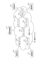
- FIG. 1 is a block diagram illustrating an example of a communication system according to the present invention.
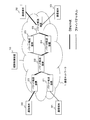
- the communication system of the present invention includes a path control device 10 and packet transfer devices 20 to 25 belonging to the communication network 1.
- FIG. 1 is an illustration of a communication system, and the number and topology of packet transfer apparatuses are not limited to the example illustrated in FIG.
- the communication terminal 30 is connected to the packet transfer device 20
- the communication terminal 31 is connected to the packet transfer device 21
- the communication terminals 32 and 33 are connected to the packet transfer device 25.
- Each packet transfer device transfers packets transmitted and received between communication terminals. Note that the number of communication terminals and which packet transfer device of the communication network 1 the communication terminal is connected to are not particularly limited.
- the route control device 10 and the individual packet transfer devices 20 to 25 are connected via a dedicated control channel, and the route control device 10 and each packet transfer device 20 to 25 are connected via the dedicated control channel. Send and receive information.
- the type of link for connecting packet transfer devices and the type of link for connecting packet transfer devices and communication terminals are not limited to one type, and may be a plurality of types.
- the example shown in FIG. 1 shows a case where there are an Ethernet link and a fiber channel link as link types.
- the link connecting the packet transfer apparatuses 20 and 22 and the link connecting the packet transfer apparatus 20 and the communication terminal 30 are Ethernet links.
- the link connecting the packet transfer apparatuses 21 and 22 and the link connecting the packet transfer apparatus 21 and the communication terminal 31 are Fiber Channel links.
- FIG. 1 shows the case where there are two types of links, the number of types of links may be three or more.
- link technologies other than Ethernet and fiber channel may be used.
- Each packet transfer device 20 to 25 transfers the received packet to the next node under the control of the route control device 10. Specifically, each of the packet transfer apparatuses 20 to 25 performs processing on the received packet according to the packet transfer rule set by the path control apparatus 10.
- the packet transfer rule is information that defines the operation of the packet transfer device when the packet transfer device receives a packet.
- the packet transfer rule includes classification information that is information for identifying a flow, and action information that is performed on a packet that is determined to belong to the flow specified by the classification information.
- the classification information is expressed as a requirement that a packet belonging to the flow satisfies, such as “the destination MAC address and the destination IP address match the MAC address and IP address of the communication terminal 33”.
- the expression mode is not particularly limited. Examples of the content of action information include, for example, “forward a received packet to a specific port”, “flood”, “discard”, etc., but the content of action information is not limited thereto.
- the action information includes a timer value.
- the timer value is a value for determining the valid period of the packet transfer rule.
- the packet transfer rule includes classification information, action information, and a timer value, but may further include other information.
- a timer value is included in the action information will be described as an example.
- the timer value may be included in the packet transfer rule even if it is not included in the action information.
- the path control device 10 generates a packet transfer rule including classification information and action information according to the flow, and sets the packet transfer rule in the packet transfer device on the communication path of the flow.
- Each of the packet transfer devices 20 to 25 decreases the timer value included in the action information of the set packet transfer rule with time (in other words, counts down), and deletes the packet transfer rule when the timer value becomes zero. To do.
- Each of the packet transfer apparatuses 20 to 25 may reset the timer value of the packet transfer rule to the initial value when receiving a packet that matches the classification information in the packet transfer rule.
- each of the packet transfer apparatuses 20 to 25 may be configured to continue counting down the timer value without receiving the initial value of the timer value even when such a packet is received.
- the packet transfer apparatuses 20 to 25 are, for example, flow switches in open flow.
- the path control device 10 is a path control device in an open flow, for example.
- the packet transfer rule is, for example, flow entry information in an open flow.
- FIG. 2 is a block diagram showing a configuration example of the route control device 10 of the present invention.
- the route control apparatus 10 includes a topology information storage unit 31, a topology information registration unit 32, a communication terminal location management unit 33, a packet transfer rule generation unit 34, a route calculation unit 35, a rule setting content storage unit 36, A packet transfer device management unit 37, a packet transfer device information storage unit 38, and an analysis information storage unit 39 are provided.
- the topology information storage unit 31 is a storage device that stores topology information representing the network topology formed by the packet transfer device group. However, the topology information storage unit 31 stores topology information for each link type. For example, as shown in FIG. 1, when there are Ethernet links and fiber channel links as the link types, the topology information storage unit 31 includes the topology information of the packet transfer apparatus group connected by the Ethernet links, and the fiber channel. And topology information of the packet transfer device groups connected by the links.
- the topology information registration unit 32 creates topology information for each link type based on the information received from each packet transfer device, and stores the created topology information in the topology information storage unit 31.
- the communication terminal location management means 33 manages to which port of which packet transfer device each communication terminal connected to the communication network 1 is connected. For example, when a terminal device transmits a packet such as a DHCP (Dynamic Host Configuration Protocol) request message, the packet transfer device connected to the communication terminal is connected to which port of the packet transfer device. Is transmitted to the route control device 10, and the communication terminal location management means 33 may hold such information.
- DHCP Dynamic Host Configuration Protocol
- Packet transfer rule generation means 34 determines classification information and action information, and generates a packet transfer rule including the classification information and action information. Further, the packet transfer rule generation unit 34 generates a packet transfer rule for each packet transfer device on the communication path. Here, the packet transfer rule generation unit 34 makes the classification information common to the packet transfer apparatuses on the communication path of the same flow. However, the action information may be determined to be different for each packet transfer apparatus.
- the packet transfer rule generation unit 34 applies the packet transfer rule to the packet transfer device in which the packet transfer rule including the same classification information as the classification information is set in the communication path of the flow specified by the classification information. Is not generated.
- the route calculation means 35 calculates the flow communication route. However, the route calculation means 35 refers to the topology information corresponding to the type of link specified from the packet of the flow, and calculates the communication route using the topology information. For example, it is assumed that a link type specified from a packet of a new flow that is a calculation target of a communication path is a fiber channel link. In this case, the route calculation means 35 refers to the topology information related to the fiber channel link among the topology information stored in the topology information storage means 31 for each type of link, and calculates the communication route using the topology information. To do. At this time, the route calculation means 35 calculates a communication route according to a standard corresponding to the type of application software used in the communication terminal that transmits and receives packets.
- the rule setting content storage means 36 is a storage device that stores information indicating what packet transfer rule is set in which packet transfer device.
- the rule setting content storage means 36 can manage what packet transfer rule is set for which packet transfer device.
- the packet transfer device management means 37 manages each packet transfer device 20-25. Specifically, the packet transfer device management unit 37 performs processing for setting the packet transfer rule generated by the packet transfer rule generation unit 34 in the packet transfer device. Then, when the packet transfer rule is set in the packet transfer device, the packet transfer device management unit 37 stores in the rule setting content storage unit 36 what packet transfer rule is set in which packet transfer device.
- the packet transfer device management unit 37 collects information from the packet transfer device and stores the collected information in the packet transfer device information storage unit 38.
- a process in which a packet transfer device that newly establishes a connection sends information to the route control device 10 and the route control device 10 stores the information is referred to as initial setting.
- information collected at the time of initial setting includes, for example, identifiers of individual packet transfer devices, port identifiers of each port of individual packet transfer devices, and types of links connected to the individual ports, Contains information related to the link.
- the packet transfer device information storage means 38 is a storage device for storing information collected from the packet transfer devices 20 to 25 by the packet transfer device management means 37 during the initial setting process of the packet transfer device. By referring to the information stored in the packet transfer device information storage unit 38, the type of each link, information related to the link, and the like can be determined.
- the packet transfer device management means 37 is an application used in a communication terminal that transmits and receives a packet based on the information related to the packet when information related to the packet of the new flow is sent from the packet transfer device. Analyze the software type.
- the packet transfer device management unit 37 may perform analysis with reference to the information stored in the analysis information storage unit 39. It can be said that the analysis of the type of application software used in the communication terminal is an aspect of the analysis of the characteristics of the communication terminal.
- the analysis information storage means 39 is a storage device that stores information for analyzing the type of application software used in a communication terminal that transmits and receives packets.
- the analysis information storage unit 39 stores information indicating the correspondence between the information extracted from the packet field and the type of application software. That is, information indicating what kind of application software is used in the communication terminal that transmits and receives the packet when the information is extracted from the packet field is stored.
- the analysis information storage unit 39 may store information indicating the correspondence between the information extracted from the packet field and the type of application software for each link type.
- the packet field referred to for specifying the type of application software may be different for each type of link specified from the packet.
- the topology information registration unit 32, the communication terminal location management unit 33, the packet transfer rule generation unit 34, the route calculation unit 35, and the packet transfer device management unit 37 are realized by a CPU of a computer that operates according to a route control program, for example.
- the program storage device (not shown) of the computer stores the route control program, and the CPU reads the program, and according to the program, the topology information registration means 32, the communication terminal location management means 33, and the packet transfer rule generation means 34
- the route calculation unit 35 and the packet transfer device management unit 37 may be operated. Each of these means may be realized by separate hardware.
- topology information storage unit 31, the rule setting content storage unit 36, the packet transfer device information storage unit 38, and the analysis information storage unit 39 may be realized by the same storage device or by separate storage devices. May be.
- FIG. 3 is a block diagram showing a configuration example of the packet transfer apparatus of the present invention.
- the packet transfer apparatus 20 includes a rule table storage unit 41, a rule management unit 42, a flow identification unit 43, an action execution unit 44, an initial setting processing unit 45, and a topology determination information providing unit 46.
- the rule table storage means 41 is a storage device that stores packet transfer rules. Since different packet transfer rules are set for different flows, the number of packet transfer rules stored in the rule table storage unit 41 is not necessarily one. A set of packet transfer rules stored in the rule table storage unit 41 is referred to as a packet transfer rule table.
- the rule management means 42 manages each packet transfer rule. For example, when the packet transfer device management unit 37 (see FIG. 2) of the route control device 10 sets a packet transfer rule in the packet transfer device, the packet transfer rule is transmitted to the packet transfer device together with a setting instruction.
- the rule management unit 42 stores the packet transfer rule received from the route control device 10 in the rule table storage unit 41 according to this instruction.
- the rule management means 42 decreases the timer value specified in each packet transfer rule stored in the rule table storage means 41 with the passage of time. Then, when the timer value becomes 0, the rule management unit 42 deletes the packet transfer rule including the timer value from the rule table storage unit 41 and transmits information to that effect to the route control device 10.
- the packet transfer device management unit 37 see FIG. 2 of the route control device 10 receives this information, the packet transfer rule information deleted from the rule table storage unit 41 in the packet transfer device is stored in the rule setting contents. It deletes from the means 36 (refer FIG. 2).
- the flow specifying unit 43 When the flow specifying unit 43 receives a packet from another node (for example, a communication terminal or another packet transfer apparatus), the flow specifying unit 43 stores a packet transfer rule including classification information matching the packet in the rule table storage unit 41. Search from the specified packet transfer rule table. The failure of the search means that a packet belonging to a new flow other than the flow corresponding to the stored packet transfer rule has been received. In this case, the flow specifying unit 43 transmits a notification (new flow detection notification) indicating that a new flow has been detected to the route control device 10.
- a notification new flow detection notification
- the flow identification unit 43 uses the new flow to identify information that can identify the communication path of the flow, information that can create classification information, and information that is used to analyze application software used in a communication terminal that transmits and receives packets belonging to the new flow. Include in detection notification. Furthermore, the flow specifying means 43 also includes the identifier of the own node (packet transfer apparatus 20 in the example shown in FIG. 3) and the port number of the own node that has received the new flow packet in the new flow detection notification.
- the information that can identify the communication path of the flow is information that can identify the passage path of the new flow to which the received packet belongs.
- address information of the source and destination communication terminals that are both end points of the communication path can be given.
- the address information of the source and destination communication terminals that are both end points of the communication path is an example of information that can specify the communication path of the flow.
- the address of the communication terminal that is the destination Address information may not be necessary.
- What to use as the classification information may be determined in advance according to the flow rate of identification. For example, when a flow is identified by a combination of various information such as a source and destination MAC address, an IP address, a source port number, and a destination port number, the packet transfer rule generation unit 34 is specified from the packet. Such information may be determined as classification information. Alternatively, when a flow is identified with coarse granularity such as only the destination port number, only the source port number, etc., the packet transfer rule generation unit 34 can determine such information specified from the packet as classification information. Good. Further, among the ports of the packet transfer device, the port number of the port that received the packet may be used as the classification information. Information that can create classification information only needs to include information that is classified by the packet transfer rule generation unit 34.
- Information used for analyzing application software used in a communication terminal that transmits and receives packets belonging to a new flow is, for example, a packet header.
- the header of the packet contains information that can identify the communication path of the flow. Therefore, if the information defined as information capable of creating the classification information is also included in the header, the flow specifying unit 43 has received the packet header of the new flow, the identifier of the own node, and the packet.
- the port number of the own node may be included in the new flow detection notification and the new flow detection notification may be transmitted to the path control device 10. If there is information other than the header of the packet and the port number of the own node that received the packet in the information determined as the information that can create the classification information, the flow specifying unit 43 also adds the information to the new flow. It may be included in the detection notification.
- the action executing means 44 executes the process indicated by the action information included in the packet transfer rule for the received packet when the flow specifying means 43 succeeds in searching for the packet transfer rule.
- the initial setting processing unit 45 responds to a request from the packet transfer device management unit 37 (see FIG. 2) of the route control device 10 when the node (packet transfer device) establishes a connection with the route control device 10.
- the information of the own node is transmitted to the route control device 10.
- the information to be transmitted includes, for example, the identifier of the own node, the port identifier of each port of the own node, the type of link connected to the individual port, information related to the link, and the like.
- the topology determination information providing means 46 transmits a packet for creating topology information for each link type (hereinafter referred to as a topology determination packet).
- the topology determination information providing unit 46 transmits a topology determination packet for each link type.
- the topology determination information providing unit 46 transmits it from the port of the own node connected to the link of that type.
- the topology determination packet transmitted from a certain packet transfer apparatus is received by another packet transfer apparatus.
- the packet transfer apparatus that has received the topology determination packet adds information to the topology determination packet and transmits the information to the route control apparatus 10.
- the topology information registration unit 32 of the route control device 10 receives the topology determination packet for each link type, and creates topology information for each link type based on the topology determination packet.
- the topology determination information providing unit 46 adds information to the topology determination packet when receiving the topology determination packet from another packet transfer apparatus, in addition to the process of transmitting the topology determination packet from the own node. Also, processing to transmit to the route control device 10 is performed.
- the rule management means 42, the flow identification means 43, the action execution means 44, the initial setting processing means 45, and the topology determination information providing means 46 are realized, for example, by a CPU of a computer that operates according to a packet transfer device program.
- the program storage device (not shown) of the computer stores the packet transfer device program, and the CPU reads the program, and in accordance with the program, the rule management means 42, the flow specifying means 43, the action execution means 44, and the initial setting. What is necessary is just to operate
- These means may be realized by separate hardware.
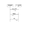
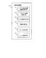
- FIG. 4 is an explanatory diagram showing an example of processing progress at the time of initial setting.
- the packet transfer device 20 will be described as an example, but the other packet transfer devices 21 to 25 perform the same processing together with the route control device 10.
- step S1 When the packet transfer device 20 is arranged in the communication network 1 and connected to the route control device 10, the initial setting processing means 45 (see FIG. 3) of the packet transfer device 20 and the packet transfer device management means 37 of the route control device 10. (See FIG. 2) establishes a connection between the packet transfer apparatus 20 and the path control apparatus 10 (step S1).
- the connection established in step S1 is, for example, a TCP connection using a control channel port number.
- the packet transfer device management unit 37 of the route control device 10 transmits an information request to the packet transfer device 20 (step S2).
- the information request is information indicating that the packet transfer device is requested to transmit information to the route control device 10.
- the initial setting processing means 45 of the packet transfer device 20 Upon receiving the information request transmitted in step S2, the initial setting processing means 45 of the packet transfer device 20 transmits information related to the packet transfer device 20 to the route control device 10 as a response to the information request (step S3).
- the packet transfer device management unit 37 of the route control device 10 receives this information, it stores it in the packet transfer device information storage unit 38.
- the initial setting processing unit 45 may transmit, for example, an IP address as the identifier of the packet transfer device itself.
- the IP address is an example of an identifier of the packet transfer device, and information other than the IP address may be transmitted as the identifier.
- the second information to be transmitted in step S3 there is information regarding each port of the packet transfer device itself (packet transfer device 20 in this example).
- the information regarding each port includes, for example, the port identifier of each port of the packet transfer apparatus, the type of link connected to each port (hereinafter sometimes referred to as link type information), and the connection to each port. It is information related to the link.
- the initial setting processing means 45 transmits these pieces of information regarding each port of the packet transfer apparatus itself to the route control apparatus 10 together with the first information (identifier of the packet transfer apparatus).
- the link type information is information representing link types having different frame types such as Ethernet, Fiber Channel, Infiniband, and the like.
- the content of the information related to the link varies depending on the type of link. For example, when the link type is Ethernet, the MAC address, the supported communication speed, the communication method (for example, full duplex, half duplex), and the like can be given as information related to the link.
- Information related to the link can also be referred to as link attribute information.
- the initial setting processing unit 45 may transmit other information in addition to the above information.
- information regarding the capability of the packet transfer apparatus itself may be transmitted.
- Examples of information on the capability of the packet transfer apparatus include information on whether or not to acquire statistical information, information on actions supported by the packet transfer apparatus, and the like.
- Examples of actions supported by the packet transfer apparatus include source / destination MAC address conversion, source / destination IP address conversion, source / destination port number conversion, and the like.
- the routing control device 10 supports the destination MAC address conversion processing when the destination MAC address conversion processing is necessary for a specific flow, for example, by collecting information on actions supported by the packet transfer device. It is possible to perform control such as specifying a packet transfer device that is present and causing the packet transfer device to perform destination MAC address conversion.
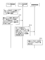
- FIG. 5 is an explanatory diagram showing an example of the progress of processing when topology information is generated.
- the packet transfer device that is the transmission source of the topology determination packet is represented by “A”
- the packet transfer device that transfers the topology determination packet to the route control device 10 is represented by “B”.
- the topology determining information providing unit 46 (see FIG. 3) of the packet transfer apparatus A selects one type from the types of links connected to the ports of the own node (packet transfer apparatus A itself) (step S11).
- step S11 For example, when a part of the plurality of ports provided in the packet transfer apparatus A is connected to the Ethernet link and the remaining ports are connected to the fiber channel link, “Ethernet”, “fiber channel” ”Is selected.
- a case where “Ethernet” is selected will be described as an example.
- the topology determination information providing means 46 of the packet transfer apparatus A uses the identifier (for example, address) of its own node (packet transfer apparatus A itself) as its topology determination packet according to the type of link selected in step S11, A packet to which an identifier of a port that outputs a topology determination packet is added is created.
- the port that outputs the topology determination packet is a port connected to the type of link selected in step S11.
- the topology determination information providing unit 46 of the packet transfer apparatus A outputs (that is, transmits) a topology determination packet to which the identifier of the own node and the identifier of the port are added from the port (step S12).
- the topology determination information providing unit 46 of the packet transfer apparatus A creates and transmits a topology determination packet for each port.
- topology determination packets are not created and transmitted for ports connected to links different from the type selected in step S11.
- the packet transfer apparatus A has four ports, the port numbers (port identifiers) “1” and “2” are connected to the Ethernet link, and the port numbers “3” and “4” are Assume that it is connected to a Fiber Channel port.
- the topology determination information providing unit 46 transmits the topology determination packet to which the identifier of the packet transfer apparatus A and the port number “1” are added from the port having the port number “1”. .
- the topology determination information providing unit 46 transmits the topology determination packet to which the identifier of the packet transfer apparatus A and the port number “2” are added from the port having the port number “2”.
- the port numbers “3” and “4” do not correspond to the “Ethernet” link, so the topology determination packet is not created and transmitted.
- the topology determination information providing unit 46 of the packet transfer apparatus B receives the topology determination packet transmitted in step S12, an identifier (for example, address) of the own node (packet transfer apparatus B) is added to the topology determination packet. And the port identifier of the port of the own node that received the topology determination packet, and transmits the topology determination packet to the route control device 10 (step S13).
- the topology information registering means of the route control device 10 indicates the topology determination packet indicating which port in which packet transfer device is connected to which port in which packet transfer device by the selected type of link. 32 receives.
- the identifier of the packet transfer device A and the port number “1” are added to the topology determination packet received by the topology determination information providing unit 46 of the packet transfer device B.
- the packet transfer apparatus B receives the topology determination packet at the port with the port number “3” of the packet transfer apparatus B itself.
- the topology determination information providing unit 46 of the packet transfer apparatus B adds the identifier of the packet transfer apparatus B itself and the port number “3” to the topology determination packet and transmits the packet to the route control apparatus 10.
- the topology determination packet indicating that the port with the port number “1” of the packet transfer apparatus A and the port with the port number “3” of the packet transfer apparatus B are connected by an Ethernet link is route-controlled.
- Device 10 receives.
- FIG. 5 shows only one packet transfer apparatus B that transfers the topology determination packet.
- any packet transfer apparatus that receives the topology determination packet transmitted in step S12 performs the process of step S13.
- the packet transfer apparatus that has received the topology determination packet to which the identifier of the packet transfer apparatus A and the port number “2” are added also executes step S13.
- each packet transfer device in the communication network 1 performs the processing of steps S11 and S12.
- the topology information registration unit 32 of the route control device 10 receives a topology determination packet for each link of the Ethernet.
- Each topology determination packet indicates which port in which packet transfer device and which port in which packet transfer device are connected by an Ethernet link. Based on each received topology determination packet, the topology information registration unit 32 creates the topology information of the packet transfer apparatus connected by the Ethernet link, and stores it in the topology information storage unit 31.
- each packet transfer device in the communication network 1 selects an unselected type (in this example, a fiber channel) in step S11, and thereafter performs the same processing.
- an unselected type in this example, a fiber channel
- the topology information of the packet transfer apparatuses connected by the fiber channel link is also created by the topology information registration means 32 and stored in the topology information storage means 31.
- the communication system stores the topology information for each link type in the topology information storage means 31 by performing the processing described in FIG. 5 for each link type.
- topology information creation processing is an example, and the communication system may create topology information for each link type by other methods.
- FIG. 6 is an explanatory diagram illustrating an example of a process progress of the communication system when a packet transmitted / received between communication terminals is transferred.
- a case where the communication terminal 30 shown in FIG. 1 transmits a packet to the communication terminal 32 will be described as an example.
- the communication terminal 30 transmits the packet to the communication terminal 32 (step S21). This packet reaches the packet transfer apparatus 20 to which the communication terminal 30 is connected.
- the flow specifying unit 43 determines whether or not a packet transfer rule that matches the received packet is stored in the rule table storage unit 41. To do.
- the packet transfer device 20 first receives a packet transmitted from the communication terminal 30 to the communication terminal 32, a packet transfer rule that matches the packet is not stored in the rule table storage unit 41 of the packet transfer device 20. Therefore, the flow specifying unit 43 of the packet transfer apparatus 20 buffers the received packet, and the identifier (for example, IP address) of the own node (packet transfer apparatus 20) and the port identifier of the port of the own node that has received the packet.
- a new flow detection notification including (for example, port number) and the header of the packet is created and transmitted to the route control device 10 (step S22).
- the header of the packet information that can identify the communication path of the flow, information that can create classification information (for example, a MAC address, an IP address, a port number, etc. regarding both the transmission source and the destination), and a new Information used for analysis of application software used in a communication terminal that transmits and receives packets belonging to a flow is included. If there is information other than the header of the packet and the port number of the own node that received the packet in the information determined as the information that can create the classification information, the flow specifying unit 43 also adds the information to the new flow. It may be included in the detection notification.
- step S22 the flow specifying unit 43 of the packet transfer apparatus 20 creates a new flow detection notification including the received packet itself, the identifier of the own node, and the port identifier of the port of the own node that has received the packet. Alternatively, it may be transmitted to the route control device 10.
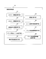
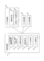
- FIG. 7 is a flowchart illustrating an example of processing progress of the path control device 10 that has received the new flow detection notification.
- the packet transfer device management unit 37 of the route control device 10 receives the new flow detection notification (step S31), the frame type of the packet of the new flow (here, the packet received by the packet transfer device 20 from the communication terminal 30). Is determined (step S32). In other words, the packet transfer device management unit 37 determines the type of link that should be the transfer route of the packet of the new flow.
- the packet transfer device management unit 37 includes the identifier of the packet transfer device that is the transmission source of the new flow detection notification included in the new flow detection notification, and the port of the port from which the packet transfer device received the packet. The type of the link connected to the port may be determined based on the information stored in the packet transfer device information storage unit 38 with reference to the identifier.
- the new flow detection notification includes the identifier of the packet transfer device 20.
- the new flow detection notification includes the port number “1” as the port identifier of the port from which the packet transfer apparatus 20 has received the packet.
- the packet transfer device information storage means 38 stores the type of link connected to each port in each packet transfer device. Accordingly, the packet transfer device management unit 37 determines the link type (packet frame type) by reading the link type information of the port of the packet transfer device specified from the new flow detection notification from the packet transfer device information storage unit 38. do it. In the above example, the link type of the port number “1” in the packet transfer device 20 may be read from the packet transfer device information storage unit 38.
- step S32 the packet transfer device management unit 37 determines that the link type is Ethernet.
- the packet transfer device management unit 37 determines the application software used in the communication terminal (in this example, the communication terminals 30 and 32) that transmits and receives a packet of a new flow based on the type determined in step S32.
- the type is analyzed (step S32).
- the packet transfer device management means 37 refers to the information stored in the analysis information storage means 39 and performs this analysis.
- the analysis information storage means 39 stores information indicating the correspondence between the content extracted from the packet field and the application software type for each link type.
- the application software type for each link type.
- Ethernet it is assumed that values such as an IP address and a port number in the Ethernet header and each of the upper headers are associated with the type of application software.
- the packet transfer device management unit 37 refers to the upper layer header from the lower layer header in order based on the type determined in step S31, and identifies the type of application software used in the communication terminal.
- the packet transfer apparatus management unit 37 refers to the type number in the Ethernet header among the packet headers, and the upper header is the IPv4 header. If it is determined that there is an IP header, the contents of the IP header are referred to following the Ethernet header.
- An application used in a communication terminal that transmits and receives packets by referring to the header of the transport layer in the same procedure, collating the content of the referenced information with the information stored in the analysis information storage unit 39 Identify the type of software.
- the route calculation means 35 determines whether or not communication of a newly generated flow is permitted (step S34).
- the route calculation unit 35 may determine whether to permit communication according to a predetermined rule for determining the operation of the packet transfer apparatus.
- the packet transfer device operation determination rule is a rule that defines the operation of the packet transfer device.
- the rule for determining the operation of the packet transfer device is a rule that “each communication terminal can communicate with any terminal other than the path control device 10 and does not perform detailed flow control regardless of the type of communication terminal”. Is predetermined. For example, it is assumed that the destination MAC address is used as the classification information.
- the route calculation means 35 determines that communication is permitted if the destination MAC address included in the new flow detection notification is the MAC address of a terminal other than the route control device 10 ( Yes in step S34). If the destination MAC address included in the new flow detection notification is the MAC address of the route control device 10, it is determined that communication is not permitted (No in step S34).
- the content of the packet transfer device operation determination rule is not limited to the above content.
- the route calculation unit 35 refers to the topology information related to the type of link determined in step S32, and a criterion corresponding to the type of application software determined in step S33. To calculate the route (step S35).
- step S35 the communication terminal location management means 33 is connected to which port of which packet transfer device the communication terminal is based on the address information of the destination communication terminal included in the new flow detection notification. Judge whether there is.
- the packet transfer device 25 connected to the destination communication terminal 32 is specified, and further, the port connected to the communication terminal 32 among the ports of the packet transfer device 25 is specified.
- the route calculation means 35 reads topology information (here, Ethernet topology information) relating to the type of link determined in step S32 from the topology information storage means 31, and the topology information and the communication terminal location management means 33 Based on the position confirmation result, a communication path from the transmission source communication terminal to the destination communication terminal is calculated.
- topology information here, Ethernet topology information
- the route calculation means 35 calculates a route according to a reference according to the type of application software determined in step S33.
- the route calculation means 35 determines whether or not each link satisfies a criterion corresponding to the type of application software based on, for example, information related to each link stored at the time of initial setting.
- a communication path from the transmission source communication terminal to the destination communication terminal may be determined using the satisfied link.
- the route calculation means 35 specifies a link that satisfies the criterion of low delay from the topology information of Ethernet, and uses that link as a transmission source.
- the communication path from the communication terminal to the destination communication terminal may be determined.
- the route calculation means 35 identifies a link that satisfies the criteria of broadband from the topology information of Ethernet, and uses that link as a transmission source.
- the communication path from the communication terminal to the destination communication terminal may be determined.
- the packet transfer rule generation unit 34 After calculating the communication path, the packet transfer rule generation unit 34 generates a packet transfer rule for each packet transfer device on the path determined in step S35 (step S36). At this time, the packet transfer rule generation unit 34 first determines the classification information using “information that can generate classification information” included in the new flow detection notification. The packet transfer rule generation unit 34 may determine a part or all of items included in the “information that can generate classification information” as classification information. What items are used as classification information is determined in advance by a network administrator, for example. The classification information is common to each packet transfer device on the route.
- the packet transfer rule generation means 34 determines forwarding to the next node on the communication path as action information for each packet transfer device on the communication path.
- the packet transfer rule generator 34 combines the classification information common to the packet transfer apparatuses on the communication path and the action information determined for each packet transfer apparatus on the communication path to set the packet transfer set in each packet transfer apparatus. Determine the rules. Note that the packet transfer rule generation unit 34 includes a timer value in the action information, but the timer value may be a predetermined value, for example.
- the packet transfer device management means 37 transmits a packet transfer rule corresponding to the packet transfer device to each packet transfer device on the communication path together with an instruction for setting the rule (step S37). For example, a packet transfer rule created for the packet transfer device 20 is transmitted to the packet transfer device 20 together with a rule setting instruction. The same applies to other packet transfer rules.
- step S37 when the rule management means 42 of each packet transfer device 20, 22, 24, 25 receives the packet transfer rule and its setting instruction from the route control device 10, it sets the packet transfer rule according to the instruction. Specifically, the received packet transfer rule is stored in the rule table storage unit 41.
- the packet transfer rule generation unit 34 creates, for example, a packet transfer rule for the packet transfer device 20 that is the transmission source of the new flow detection notification. (Step S36).
- the packet transfer rule generation unit 34 may determine part or all of the items included in “information that can generate classification information” as classification information. In this case, the packet transfer rule generation unit 34 may create action information that instructs to discard the packet.
- the packet transfer rule generation unit 34 creates a packet transfer rule including this classification information and action information. Note that, for example, a predetermined value may be used as the timer value included in the action information.
- step S37 for setting this packet transfer rule in the packet transfer device 20 is the same as the operation already described. Note that, here, an example has been described in which a packet transfer rule is set for the packet transfer device 20 that is the transmission source of the new flow detection notification when communication is not permitted. The same packet transfer rule may be set for the packet transfer apparatus.
- step S23 When the setting of the packet transfer rule for each of the packet transfer devices 20, 22, 24, and 25 on the communication path is completed in the process of step S23 (steps S31 to S37 shown in FIG. 7) shown in FIG.
- the action execution unit 44 transfers the buffered packet according to the set packet transfer rule (step S24, see FIG. 6). That is, the packet is transferred to the packet transfer device 22 which is the next node as defined by the action information of the set packet transfer rule.
- packet transfer rules that match this packet are set in the packet transfer apparatuses 22, 24, and 25 on the communication path determined by the path control apparatus 10. Therefore, in each packet transfer device 22, 24, 25, when the packet is received, the flow specifying unit 43 searches for a packet transfer rule that matches the packet, and the action executing unit 44 determines the next packet according to the packet transfer rule. Transfer to the node (steps S25, S26, S27). As a result, the packet reaches the destination communication terminal 32.
- the packet transfer devices 20 and 22 are transmitted. , 24, and 25 may transfer the packet in accordance with the packet transfer rule set in each packet transfer device without making an inquiry to the route control device 10.
- the communication system of the present invention may perform the same processing as described above.
- the communication system of the present invention may perform the same processing as described above.
- the path control device 10 stores topology information for each type of link. Further, when receiving the new flow detection notification, the routing control device 10 identifies the type of link through which the packet of the new flow passes, and analyzes the type of application software used in the communication terminal that transmits and receives the packet. To do. Then, the route control device 10 uses the topology information corresponding to the identified link type to calculate the communication route according to the standard according to the type of the application software, and sets the packet transfer rule to the packet transfer device on the route To do. Therefore, according to the present invention, even when there are a plurality of types of link of the packet transfer apparatus forming the communication network, the flow path can be appropriately determined.
- each packet transfer device may notify the route control device 10 that this function (frame encapsulation function) is provided. Then, the path control device 10 may calculate a path of a frame in which another type of frame is stored in the payload in the path calculation based on the new flow detection.
- the communication terminal position management means 33 specifies the positions of the transmission source communication terminal and the destination communication terminal. Then, the route calculation unit 35 determines that the two communication terminals are connected to different communication networks separated by different link systems. Further, the route calculation means 35 determines from the result of the initial setting that there is a packet transfer apparatus that can communicate between two different points by encapsulating the frame. Then, the route calculation means 35 calculates the following three routes.
- the first route is a route from a packet transmission source communication terminal to a packet transfer device (denoted as P) belonging to the same communication network as the communication terminal and having a packet encapsulation function.
- the second route is a route from the packet transfer device P to a packet transfer device (denoted as Q) that belongs to the same communication network as the destination terminal device and has a packet encapsulation function.
- the third route is a route from the packet transfer apparatus Q to the destination communication terminal.
- FIG. 8 is a block diagram showing an example of the minimum configuration of the communication system of the present invention.
- FIG. 9 is a block diagram showing an example of the minimum configuration of the path control device of the present invention.
- FIG. 10 is a block diagram showing an example of the minimum configuration of the packet transfer apparatus of the present invention.
- the communication system of the present invention includes a plurality of packet transfer apparatuses 80 that transfer received packets, and a path control apparatus 70 that controls packet communication paths by setting packet transfer rules in each packet transfer apparatus 80 ( (See FIG. 8).
- the packet transfer device 80 includes an information transmission unit 81 and a new flow detection notification unit 82 (see FIGS. 8 and 10).
- the information transmission unit 81 (for example, the initial setting processing unit 45) at least displays the identifier of the own node, the port identifier of each port of the own node, and the type of link connected to each port of the own node. 70.
- the new flow detection notification means 82 receives the information about the packet, the identifier of the own node, and the packet.
- a new flow detection notification including the port identifier of the port is transmitted to the path control device.
- the route control device 70 includes a packet transfer device information storage unit 71, a topology information storage unit 72, a link type determination unit 73, a route calculation unit 74, a rule generation unit 75, and a rule transmission unit 76. (See FIGS. 8 and 9).
- Packet transfer device information storage unit 71 (for example, packet transfer device information storage unit 38) stores information received from information transmission unit 81 of each packet transfer device 80. That is, for each packet transfer device, the packet transfer device information storage unit 71 includes at least the identifier of the packet transfer device, the port identifier of each port of the packet transfer device, and the type of link connected to each port of the packet transfer device. And remember.
- the topology information storage unit 72 (for example, the topology information storage unit 31) stores the topology information of the packet transfer device 80 for each type of link connected to each port of the packet transfer device 80.
- the link type determination unit 73 (for example, the packet transfer device management unit 37 executing step S32) receives the new flow detection notification from the packet transfer device 80, the identifier of the packet transfer device included in the new flow detection notification Based on the port identifier and the information stored in the packet transfer device information storage unit 71, the type of link through which the packet received by the packet transfer device passes is determined.
- the route calculation unit 74 calculates a packet communication route based on the topology information related to the link type determined by the link type determination unit 73.
- the rule generation means 75 (for example, the packet transfer rule generation means 34) generates a packet transfer rule for each packet transfer device on the communication path.
- the rule transmission unit 76 (for example, the packet transfer device management unit 37 executing step S37) transmits the generated packet transfer rule for each packet transfer device on the communication path.
- the same effect can be obtained with the route control device 70 of the present invention.
- the packet transfer device 80 of the present invention can be combined with the route control device 70 to obtain the same effect.
- a plurality of packet transfer devices that transfer received packets, and a route control device that controls packet communication paths by setting packet transfer rules in each packet transfer device, Information transmitting means for transmitting at least the identifier of the own node, the port identifier of each port of the own node, and the type of link connected to each port of the own node to the routing device, and a packet that matches the received packet New flow detection notification means for transmitting a new flow detection notification including information on the packet, an identifier of the own node, and a port identifier of the port that has received the packet to the path control device when no forwarding rule is held And the routing device stores packets received from the information transmission means of each packet transfer device.
- the link of the link through which the packet received by the packet transfer device passes A link type determining unit for determining the type, a route calculating unit for calculating the communication path of the packet based on the topology information on the link type determined by the link type determining unit, and for each packet transfer device on the communication path
- Rule generation means for generating a packet transfer rule; and packet transfer on the communication path.
- Communication system comprising for each device, and a rule transmitting means for transmitting the generated packet transfer rule.
- each packet transfer device The information transmission means of each packet transfer device is connected to at least the identifier of the own node, the port identifier of each port of the own node, and each port of the own node when establishing a connection with the routing control device.
- the path control device includes an analysis unit that analyzes characteristics of a communication terminal that transmits and receives the packet based on information on the packet included in the new flow detection notification.
- the communication system according to Supplementary Note 1 or Supplementary Note 2, wherein the route calculation unit calculates a communication route according to the characteristics of the communication terminal based on the topology information regarding the link type determined by the link type determination unit.
- the route control device includes an analysis unit that analyzes the type of application software used in the communication terminal that transmits and receives the packet based on information about the packet included in the new flow detection notification, and the route calculation unit includes: The communication system according to any one of appendix 1 to appendix 3, wherein a communication path corresponding to a type of application software used in the communication terminal is calculated based on topology information related to a link type determined by a link type determination unit. .
- a route control device that controls a packet communication route by setting a packet transfer rule in each packet transfer device.
- a packet transfer device For each packet transfer device, at least an identifier of the packet transfer device, a packet transfer device A packet transfer device information storage means for storing a port identifier of each port and a type of link connected to each port of the packet transfer device;
- topology information storage means For each link type connected to each port of the packet transfer device, topology information storage means for storing the topology information of the packet transfer device, information on the packet of the new flow received by the packet transfer device from the packet transfer device, When receiving a new flow detection notification including the identifier of the packet transfer device and the port identifier of the port that received the packet, the identifier and port identifier of the packet transfer device included in the new flow detection notification, Link type determination means for determining the type of link through which the packet received by the packet transfer apparatus passes based on the information stored in the packet transfer apparatus information storage means, and the link type determined by the link type determination means Calculate the communication
- route calculation means is the link classification which the link classification determination means determined 6.
- the path control device which calculates a communication path according to characteristics of the communication terminal based on topology information regarding.
- a packet transfer device for transferring a received packet in accordance with a packet transfer rule generated by a routing device, wherein at least an identifier of the own node, a port identifier of each port of the own node, and each of the own node Information transmitting means for transmitting the type of link connected to the port to the routing device, and when not holding a packet transfer rule that matches the received packet, information on the packet, an identifier of the own node,
- a packet transfer apparatus comprising: a new flow detection notification means for transmitting a new flow detection notification including a port identifier of a port that has received the packet to a route control apparatus.
- the information transmitting means At the time of establishing a connection with the path control device, the information transmitting means at least includes the identifier of the own node, the port identifier of each port of the own node, and the type of link connected to each port of the own node.
- Item 8 The packet transfer device according to appendix 7, which is transmitted to the route control device.
- Each of a plurality of packet transfer apparatuses that transfer received packets includes at least an identifier of the own node, a port identifier of each port of the own node, and a type of link connected to each port of the own node
- For each packet transfer device at least the identifier of the packet transfer device, the port identifier of each port of the packet transfer device, and the packet transfer device The type of link connected to each port is stored in the packet transfer device information storage means.
- the packet transfer device When the packet transfer device does not hold a packet transfer rule that matches the received packet, Route a new flow detection notification that includes the node identifier and the port identifier of the port that received the packet
- the packet transfer device identifier and the port identifier included in the new flow detection notification are stored in the packet transfer device information storage means. Based on the information, determine a type of link through which the packet received by the packet transfer device passes, calculate a communication path of the packet based on topology information regarding the determined link type, and on the communication path
- a path control method comprising: generating a packet transfer rule for each packet transfer apparatus; and transmitting the generated packet transfer rule for each packet transfer apparatus on the communication path.
- a route control program installed in a computer for controlling a packet communication route by setting a packet transfer rule in each packet transfer device, and at least a packet transfer for each packet transfer device.
- An information registration process for storing the identifier of the device, the port identifier of each port of the packet transfer device, and the type of link connected to each port of the packet transfer device in the packet transfer device information storage means, from the packet transfer device,
- the new flow detection notification Identifier and port identification of the packet transfer device included Link type determination processing for determining the type of link through which the packet received by the packet transfer device passes based on the information stored in the packet transfer device information storage means, the link type determined by the link type determination processing
- a path calculation process for calculating a communication path of the packet based on topology information regarding, a rule generation process for generating
- a packet transfer device program for executing a new flow detection notification process for transmitting a new flow detection notification including information related to the packet, an identifier of the own node, and a port identifier of a port that has received the packet to a route control device .
- Additional remark 13 The program for packet transfer apparatuses of Additional remark 12 which makes a computer perform an information transmission process at the time of the connection establishment with a route control apparatus.
- a plurality of packet transfer apparatuses that transfer received packets and a path control apparatus that controls packet communication paths by setting packet transfer rules in each packet transfer apparatus.
- Information transmitting unit that transmits at least the identifier of the own node, the port identifier of each port of the own node, and the type of link connected to each port of the own node, and a packet that matches the received packet
- a new flow detection notification unit that transmits a new flow detection notification including information on the packet, an identifier of the own node, and a port identifier of the port that has received the packet to the path control device when the forwarding rule is not held
- a packet transfer unit that stores information received from the information transmission unit of each packet transfer device.
- a location information storage unit a topology information storage unit that stores topology information of the packet transfer device for each type of link connected to each port of the packet transfer device, and a new flow detection notification received from the packet transfer device
- a link type determination unit for determining the packet, a route calculation unit for calculating the communication path of the packet based on the topology information regarding the link type determined by the link type determination unit, and a packet for each packet transfer device on the communication path
- a rule generation unit that generates a transfer rule and a packet generation unit that is generated for each packet transfer device on the communication path.
- Communication system comprising a rule transmitter which transmits the packet forwarding rules were.
- each packet transfer device is connected to at least the identifier of the own node, the port identifier of each port of the own node, and each port of the own node when establishing a connection with the routing control device.
- the route control device includes an analysis unit that analyzes characteristics of the communication terminal that transmits and receives the packet based on information about the packet included in the new flow detection notification.
- the route calculation unit includes a link type determination unit 15.
- the communication system according to supplementary note 14, wherein a communication path corresponding to characteristics of the communication terminal is calculated based on topology information relating to the determined link type.
- the path control device includes an analysis unit that analyzes the type of application software used in the communication terminal that transmits and receives the packet based on information about the packet included in the new flow detection notification.
- the communication system according to supplementary note 14 wherein a communication path according to a type of application software used in the communication terminal is calculated based on topology information related to a link type determined by a link type determination unit.
- a path control device that controls a packet communication path by setting a packet transfer rule in each packet transfer device, and includes at least an identifier of the packet transfer device, a packet transfer device Packet transfer device information storage unit for storing the port identifier of each port and the type of link connected to each port of the packet transfer device, and packet transfer for each type of link connected to each port of the packet transfer device
- a topology information storage unit for storing the topology information of the device, information on a packet of a new flow received by the packet transfer device from the packet transfer device, an identifier of the packet transfer device, and a port identifier of the port that has received the packet
- a new flow detection notification including Link type determination that determines the type of link through which a packet received by the packet transfer device passes based on the identifier and port identifier of the packet transfer device included in the information and the information stored in the packet transfer device information storage unit
- a route calculation unit that calculates a communication route of the packet based on topology information related to the
- the route control device (Additional remark 19) It has an analysis part which analyzes the characteristic of the communication terminal which transmits / receives the said packet based on the information regarding the packet contained in the new flow detection notification, and the route calculation part is the type of link determined by the link type determination part Item 19.
- the route control device which calculates a communication route according to characteristics of the communication terminal on the basis of topology information regarding.
- a packet transfer device for transferring a received packet in accordance with a packet transfer rule generated by a routing device, wherein at least an identifier of the own node, a port identifier of each port of the own node, and each of the own node
- An information transmission unit that transmits the type of link connected to the port to the routing device, and a packet transfer rule that conforms to the received packet, information about the packet, an identifier of the own node,
- a packet transfer apparatus comprising: a new flow detection notification unit that transmits a new flow detection notification including a port identifier of a port that has received the packet to a route control device.
- the information transmitting unit At the time of establishing a connection with the path control device, the information transmitting unit at least determines the identifier of the own node, the port identifier of each port of the own node, and the type of link connected to each port of the own node. Item 20. The packet transfer device according to appendix 20, which is transmitted to the route control device.
- Each of a plurality of packet transfer apparatuses that transfer received packets includes at least an identifier of the own node, a port identifier of each port of the own node, and a type of link connected to each port of the own node
- For each packet transfer device at least the identifier of the packet transfer device, the port identifier of each port of the packet transfer device, and the packet transfer device The type of link connected to each port is stored in the packet transfer device information storage unit.
- the packet transfer device When the packet transfer device does not have a packet transfer rule that matches the received packet, Route a new flow detection notification that includes the node identifier and the port identifier of the port that received the packet
- the packet transfer device identifier and the port identifier included in the new flow detection notification are stored in the packet transfer device information storage unit. Based on the information, determine a type of link through which the packet received by the packet transfer device passes, calculate a communication path of the packet based on topology information regarding the determined link type, and on the communication path
- a path control method comprising: generating a packet transfer rule for each packet transfer apparatus; and transmitting the generated packet transfer rule for each packet transfer apparatus on the communication path.
- a route control program installed in a computer for controlling a packet communication route by setting a packet transfer rule in each packet transfer device, The computer stores, for each packet transfer device, at least a packet transfer device identifier, a port identifier of each port of the packet transfer device, and a type of link connected to each port of the packet transfer device.
- the packet transfer device receives the packet transfer device based on the identifier and port identifier of the packet transfer device included in the new flow detection notification and the information stored in the packet transfer device information storage unit.
- Link type determination process that determines the type of link through which the packet passes, A route calculation process for calculating the communication path of the packet, a rule generation process for generating a packet transfer rule for each packet transfer device on the communication path, based on topology information related to the link type determined in the link type determination process; and A path control program for executing a rule transmission process for transmitting the generated packet transfer rule for each packet transfer device on the communication path.
- the present invention can be suitably applied to a communication system including a plurality of packet transfer apparatuses that transfer packets and a path control apparatus that controls each packet transfer apparatus to control a flow path.
Abstract
Description
図1は、本発明の通信システムの例を示すブロック図である。本発明の通信システムは、経路制御装置10と、通信ネットワーク1に属するパケット転送装置20~25とを備える。図1では、6台のパケット転送装置20~25を図示しているが、図1は通信システムの例示であり、パケット転送装置の台数やトポロジーは、図1に示す例に限定されない。図1に示す例では、通信端末30がパケット転送装置20に接続され、通信端末31がパケット転送装置21に接続され、通信端末32,33がパケット転送装置25に接続されている。そして、各パケット転送装置は、通信端末間で送受信されるパケットを転送する。なお、通信端末の台数や、通信端末が通信ネットワーク1のどのパケット転送装置に接続されるのかに関しても、特に限定されない。 Hereinafter, embodiments of the present invention will be described with reference to the drawings.
FIG. 1 is a block diagram illustrating an example of a communication system according to the present invention. The communication system of the present invention includes a
図4は、初期設定時の処理経過の例を示す説明図である。図4では、パケット転送装置20を例にして説明するが、他のパケット転送装置21~25も経路制御装置10とともに同様の処理を行う。 Next, the operation will be described.
FIG. 4 is an explanatory diagram showing an example of processing progress at the time of initial setting. In FIG. 4, the
経路計算手段は、リンク種別判定手段が判定したリンクの種別に関するトポロジー情報に基づいて、前記通信端末の特徴に応じた通信経路を計算する付記1または付記2に記載の通信システム。 (Supplementary Note 3) The path control device includes an analysis unit that analyzes characteristics of a communication terminal that transmits and receives the packet based on information on the packet included in the new flow detection notification.
The communication system according to Supplementary Note 1 or
パケット転送装置の各ポートに接続されるリンクの種別毎に、パケット転送装置のトポロジー情報を記憶するトポロジー情報記憶手段と、パケット転送装置から、当該パケット転送装置が受信した新規フローのパケットに関する情報と、当該パケット転送装置の識別子と、前記パケットを受信したポートのポート識別子とを含む新規フロー検出通知を受信したときに、当該新規フロー検出通知に含まれる前記パケット転送装置の識別子およびポート識別子と、パケット転送装置情報記憶手段に記憶された情報とに基づいて、前記パケット転送装置が受信したパケットが通過するリンクの種別を判定するリンク種別判定手段と、リンク種別判定手段が判定したリンクの種別に関するトポロジー情報に基づいて、前記パケットの通信経路を計算する経路計算手段と、前記通信経路上のパケット転送装置毎にパケット転送ルールを生成するルール生成手段と、前記通信経路上のパケット転送装置毎に、生成されたパケット転送ルールを送信するルール送信手段とを備えることを特徴とする経路制御装置。 (Supplementary Note 5) A route control device that controls a packet communication route by setting a packet transfer rule in each packet transfer device. For each packet transfer device, at least an identifier of the packet transfer device, a packet transfer device A packet transfer device information storage means for storing a port identifier of each port and a type of link connected to each port of the packet transfer device;
For each link type connected to each port of the packet transfer device, topology information storage means for storing the topology information of the packet transfer device, information on the packet of the new flow received by the packet transfer device from the packet transfer device, When receiving a new flow detection notification including the identifier of the packet transfer device and the port identifier of the port that received the packet, the identifier and port identifier of the packet transfer device included in the new flow detection notification, Link type determination means for determining the type of link through which the packet received by the packet transfer apparatus passes based on the information stored in the packet transfer apparatus information storage means, and the link type determined by the link type determination means Calculate the communication path of the packet based on the topology information A route calculation unit, a rule generation unit that generates a packet transfer rule for each packet transfer device on the communication route, and a rule transmission unit that transmits the generated packet transfer rule for each packet transfer device on the communication route; A path control device comprising:
を実行させるための経路制御プログラム。 (Supplementary note 10) A route control program installed in a computer for controlling a packet communication route by setting a packet transfer rule in each packet transfer device, and at least a packet transfer for each packet transfer device. An information registration process for storing the identifier of the device, the port identifier of each port of the packet transfer device, and the type of link connected to each port of the packet transfer device in the packet transfer device information storage means, from the packet transfer device, When a new flow detection notification including information on a packet of a new flow received by the packet transfer device, an identifier of the packet transfer device, and a port identifier of the port receiving the packet is received, the new flow detection notification Identifier and port identification of the packet transfer device included Link type determination processing for determining the type of link through which the packet received by the packet transfer device passes based on the information stored in the packet transfer device information storage means, the link type determined by the link type determination processing A path calculation process for calculating a communication path of the packet based on topology information regarding, a rule generation process for generating a packet transfer rule for each packet transfer apparatus on the communication path, and for each packet transfer apparatus on the communication path A route control program for causing the server to execute a rule transmission process for transmitting the generated packet transfer rule.
経路計算処理で、リンク種別判定処理で判定されたリンクの種別に関するトポロジー情報に基づいて、前記通信端末の特徴に応じた通信経路を計算させる付記10に記載の経路制御プログラム。 (Additional remark 11) Let a computer perform the analysis process which analyzes the characteristic of the communication terminal which transmits / receives the said packet based on the information regarding the packet contained in a new flow detection notification,
The route control program according to
前記コンピュータに、パケット転送装置毎に、少なくとも、パケット転送装置の識別子と、パケット転送装置の各ポートのポート識別子と、パケット転送装置の各ポートに接続されるリンクの種別とをパケット転送装置情報記憶部に記憶させる情報登録処理、パケット転送装置から、当該パケット転送装置が受信した新規フローのパケットに関する情報と、当該パケット転送装置の識別子と、前記パケットを受信したポートのポート識別子とを含む新規フロー検出通知を受信したときに、当該新規フロー検出通知に含まれる前記パケット転送装置の識別子およびポート識別子と、パケット転送装置情報記憶部に記憶させた情報とに基づいて、前記パケット転送装置が受信したパケットが通過するリンクの種別を判定するリンク種別判定処理、リンク種別判定処理で判定したリンクの種別に関するトポロジー情報に基づいて、前記パケットの通信経路を計算する経路計算処理、前記通信経路上のパケット転送装置毎にパケット転送ルールを生成するルール生成処理、および、前記通信経路上のパケット転送装置毎に、生成されたパケット転送ルールを送信するルール送信処理を実行させるための経路制御プログラム。 (Supplementary note 23) A route control program installed in a computer for controlling a packet communication route by setting a packet transfer rule in each packet transfer device,
The computer stores, for each packet transfer device, at least a packet transfer device identifier, a port identifier of each port of the packet transfer device, and a type of link connected to each port of the packet transfer device. Information registration process to be stored in the unit, information about the packet of the new flow received by the packet transfer device from the packet transfer device, the identifier of the packet transfer device, and the port identifier of the port that received the packet When the detection notification is received, the packet transfer device receives the packet transfer device based on the identifier and port identifier of the packet transfer device included in the new flow detection notification and the information stored in the packet transfer device information storage unit. Link type determination process that determines the type of link through which the packet passes, A route calculation process for calculating the communication path of the packet, a rule generation process for generating a packet transfer rule for each packet transfer device on the communication path, based on topology information related to the link type determined in the link type determination process; and A path control program for executing a rule transmission process for transmitting the generated packet transfer rule for each packet transfer device on the communication path.
経路計算処理で、リンク種別判定処理で判定されたリンクの種別に関するトポロジー情報に基づいて、前記通信端末の特徴に応じた通信経路を計算させる付記23に記載の経路制御プログラム。 (Additional remark 24) Let a computer perform the analysis process which analyzes the characteristic of the communication terminal which transmits / receives the said packet based on the information regarding the packet contained in the new flow detection notification,
24. The route control program according to
20~25 パケット転送装置
31 トポロジー情報記憶手段
32 トポロジー情報登録手段
33 通信端末位置管理手段
34 パケット転送ルール生成手段
35 経路計算手段
36 ルール設定内容記憶手段
37 パケット転送装置管理手段
38 パケット転送装置情報記憶手段
39 解析用情報記憶手段
41 ルールテーブル記憶手段
42 ルール管理手段
43 フロー特定手段
44 アクション実行手段
45 初期設定処理手段
46 トポロジー決定用情報提供手段 DESCRIPTION OF
Claims (10)
- 受信したパケットを転送する複数のパケット転送装置と、
各パケット転送装置にパケット転送ルールを設定することによりパケットの通信経路を制御する経路制御装置とを備え、
各パケット転送装置は、
少なくとも、自ノードの識別子と、自ノードの各ポートのポート識別子と、自ノードの各ポートに接続されるリンクの種別とを経路制御装置に送信する情報送信手段と、
受信したパケットに適合するパケット転送ルールを保持していない場合に、前記パケットに関する情報と、自ノードの識別子と、前記パケットを受信したポートのポート識別子とを含む新規フロー検出通知を経路制御装置に送信する新規フロー検出通知手段とを含み、
経路制御装置は、
各パケット転送装置の情報送信手段から受信した情報を記憶するパケット転送装置情報記憶手段と、
パケット転送装置の各ポートに接続されるリンクの種別毎に、パケット転送装置のトポロジー情報を記憶するトポロジー情報記憶手段と、
パケット転送装置から新規フロー検出通知を受信したときに、当該新規フロー検出通知に含まれる前記パケット転送装置の識別子およびポート識別子と、パケット転送装置情報記憶手段に記憶された情報とに基づいて、前記パケット転送装置が受信したパケットが通過するリンクの種別を判定するリンク種別判定手段と、
リンク種別判定手段が判定したリンクの種別に関するトポロジー情報に基づいて、前記パケットの通信経路を計算する経路計算手段と、
前記通信経路上のパケット転送装置毎にパケット転送ルールを生成するルール生成手段と、
前記通信経路上のパケット転送装置毎に、生成されたパケット転送ルールを送信するルール送信手段とを含む
ことを特徴とする通信システム。 A plurality of packet transfer devices for transferring received packets;
A path control device that controls packet communication paths by setting packet transfer rules in each packet transfer device;
Each packet forwarding device
Information transmitting means for transmitting at least the identifier of the own node, the port identifier of each port of the own node, and the type of link connected to each port of the own node, to the routing device;
When a packet transfer rule that matches the received packet is not held, a new flow detection notification including information on the packet, an identifier of the own node, and a port identifier of the port that has received the packet is sent to the routing device. A new flow detection notification means for transmitting,
The routing device
Packet transfer device information storage means for storing information received from the information transmission means of each packet transfer device;
Topology information storage means for storing the topology information of the packet transfer device for each type of link connected to each port of the packet transfer device;
When receiving a new flow detection notification from the packet transfer device, based on the identifier and port identifier of the packet transfer device included in the new flow detection notification, and the information stored in the packet transfer device information storage means, Link type determination means for determining the type of link through which the packet received by the packet transfer device passes;
A route calculation unit that calculates a communication route of the packet based on topology information related to a link type determined by the link type determination unit;
Rule generation means for generating a packet transfer rule for each packet transfer device on the communication path;
And a rule transmission means for transmitting the generated packet transfer rule for each packet transfer device on the communication path. - 各パケット転送装置の情報送信手段は、経路制御装置とのコネクション確立時に、少なくとも、自ノードの識別子と、自ノードの各ポートのポート識別子と、自ノードの各ポートに接続されるリンクの種別とを経路制御装置に送信する
請求項1に記載の通信システム。 At the time of establishing a connection with the routing control device, the information transmission means of each packet transfer device at least includes the identifier of the own node, the port identifier of each port of the own node, and the type of link connected to each port of the own node. The communication system according to claim 1, wherein the communication system is transmitted to a route control device. - 経路制御装置は、
新規フロー検出通知に含まれるパケットに関する情報に基づいて、前記パケットを送受信する通信端末の特徴を解析する解析手段を備え、
経路計算手段は、リンク種別判定手段が判定したリンクの種別に関するトポロジー情報に基づいて、前記通信端末の特徴に応じた通信経路を計算する
請求項1または請求項2に記載の通信システム。 The routing device
Based on information about the packet included in the new flow detection notification, comprising analysis means for analyzing the characteristics of the communication terminal that transmits and receives the packet,
The communication system according to claim 1, wherein the route calculation unit calculates a communication route according to characteristics of the communication terminal based on the topology information regarding the link type determined by the link type determination unit. - 経路制御装置は、
新規フロー検出通知に含まれるパケットに関する情報に基づいて、前記パケットを送受信する通信端末で用いられるアプリケーションソフトウェアの種類を解析する解析手段を備え、
経路計算手段は、リンク種別判定手段が判定したリンクの種別に関するトポロジー情報に基づいて、前記通信端末で用いられるアプリケーションソフトウェアの種類に応じた通信経路を計算する
請求項1から請求項3のうちのいずれか1項に記載の通信システム。 The routing device
Based on information about the packet included in the new flow detection notification, comprising analysis means for analyzing the type of application software used in the communication terminal that transmits and receives the packet,
The route calculation unit calculates a communication route according to the type of application software used in the communication terminal based on the topology information regarding the link type determined by the link type determination unit. The communication system according to any one of the above. - 各パケット転送装置にパケット転送ルールを設定することによりパケットの通信経路を制御する経路制御装置であって、
パケット転送装置毎に、少なくとも、パケット転送装置の識別子と、パケット転送装置の各ポートのポート識別子と、パケット転送装置の各ポートに接続されるリンクの種別とを記憶するパケット転送装置情報記憶手段と、
パケット転送装置の各ポートに接続されるリンクの種別毎に、パケット転送装置のトポロジー情報を記憶するトポロジー情報記憶手段と、
パケット転送装置から、当該パケット転送装置が受信した新規フローのパケットに関する情報と、当該パケット転送装置の識別子と、前記パケットを受信したポートのポート識別子とを含む新規フロー検出通知を受信したときに、当該新規フロー検出通知に含まれる前記パケット転送装置の識別子およびポート識別子と、パケット転送装置情報記憶手段に記憶された情報とに基づいて、前記パケット転送装置が受信したパケットが通過するリンクの種別を判定するリンク種別判定手段と、
リンク種別判定手段が判定したリンクの種別に関するトポロジー情報に基づいて、前記パケットの通信経路を計算する経路計算手段と、
前記通信経路上のパケット転送装置毎にパケット転送ルールを生成するルール生成手段と、
前記通信経路上のパケット転送装置毎に、生成されたパケット転送ルールを送信するルール送信手段とを備える
ことを特徴とする経路制御装置。 A path control device that controls a packet communication path by setting a packet transfer rule in each packet transfer device,
Packet transfer device information storage means for storing at least the identifier of the packet transfer device, the port identifier of each port of the packet transfer device, and the type of link connected to each port of the packet transfer device for each packet transfer device ,
Topology information storage means for storing the topology information of the packet transfer device for each type of link connected to each port of the packet transfer device;
When a new flow detection notification including information on a packet of a new flow received by the packet transfer device, an identifier of the packet transfer device, and a port identifier of a port that has received the packet is received from the packet transfer device. Based on the identifier and port identifier of the packet transfer device included in the new flow detection notification and the information stored in the packet transfer device information storage means, the type of link through which the packet received by the packet transfer device passes is determined. A link type determination means for determining;
A route calculation unit that calculates a communication route of the packet based on topology information related to a link type determined by the link type determination unit;
Rule generation means for generating a packet transfer rule for each packet transfer device on the communication path;
A path control device comprising: rule transmission means for transmitting the generated packet transfer rule for each packet transfer device on the communication path. - 新規フロー検出通知に含まれるパケットに関する情報に基づいて、前記パケットを送受信する通信端末の特徴を解析する解析手段を備え、
経路計算手段は、リンク種別判定手段が判定したリンクの種別に関するトポロジー情報に基づいて、前記通信端末の特徴に応じた通信経路を計算する
請求項5に記載の経路制御装置。 Based on information about the packet included in the new flow detection notification, comprising analysis means for analyzing the characteristics of the communication terminal that transmits and receives the packet,
The route control device according to claim 5, wherein the route calculation unit calculates a communication route according to characteristics of the communication terminal based on topology information related to a link type determined by the link type determination unit. - 経路制御装置が生成したパケット転送ルールに従って、受信したパケットを転送するパケット転送装置であって、
少なくとも、自ノードの識別子と、自ノードの各ポートのポート識別子と、自ノードの各ポートに接続されるリンクの種別とを経路制御装置に送信する情報送信手段と、
受信したパケットに適合するパケット転送ルールを保持していない場合に、前記パケットに関する情報と、自ノードの識別子と、前記パケットを受信したポートのポート識別子とを含む新規フロー検出通知を経路制御装置に送信する新規フロー検出通知手段とを備える
ことを特徴とするパケット転送装置。 A packet transfer device that transfers a received packet according to a packet transfer rule generated by a routing device,
Information transmitting means for transmitting at least the identifier of the own node, the port identifier of each port of the own node, and the type of link connected to each port of the own node, to the routing device;
When a packet transfer rule that matches the received packet is not held, a new flow detection notification including information on the packet, an identifier of the own node, and a port identifier of the port that has received the packet is sent to the routing device. A packet transfer apparatus comprising: a new flow detection notification means for transmitting. - 受信したパケットを転送する複数のパケット転送装置が、それぞれ、
少なくとも、自ノードの識別子と、自ノードの各ポートのポート識別子と、自ノードの各ポートに接続されるリンクの種別とを経路制御装置に送信し、
各パケット転送装置を制御する経路制御装置が、
パケット転送装置毎に、少なくとも、パケット転送装置の識別子と、パケット転送装置の各ポートのポート識別子と、パケット転送装置の各ポートに接続されるリンクの種別とをパケット転送装置情報記憶手段に記憶させ、
パケット転送装置が、
受信したパケットに適合するパケット転送ルールを保持していない場合に、前記パケットに関する情報と、自ノードの識別子と、前記パケットを受信したポートのポート識別子とを含む新規フロー検出通知を経路制御装置に送信し、
経路制御装置が、
前記新規フロー検出通知を受信したときに、当該新規フロー検出通知に含まれる前記パケット転送装置の識別子およびポート識別子と、パケット転送装置情報記憶手段に記憶させた情報とに基づいて、前記パケット転送装置が受信したパケットが通過するリンクの種別を判定し、
判定したリンクの種別に関するトポロジー情報に基づいて、前記パケットの通信経路を計算し、
前記通信経路上のパケット転送装置毎にパケット転送ルールを生成し、
前記通信経路上のパケット転送装置毎に、生成したパケット転送ルールを送信する
ことを特徴とする経路制御方法。 Multiple packet transfer devices that transfer received packets,
Sending at least the identifier of the own node, the port identifier of each port of the own node, and the type of link connected to each port of the own node to the routing device;
A route control device that controls each packet transfer device,
For each packet transfer device, at least the packet transfer device identifier, the port identifier of each port of the packet transfer device, and the type of link connected to each port of the packet transfer device are stored in the packet transfer device information storage means. ,
The packet transfer device
When a packet transfer rule that matches the received packet is not held, a new flow detection notification including information on the packet, an identifier of the own node, and a port identifier of the port that has received the packet is sent to the routing device. Send
The routing device
When receiving the new flow detection notification, based on the identifier and port identifier of the packet transfer device included in the new flow detection notification and information stored in the packet transfer device information storage means, the packet transfer device Determines the type of link through which the received packet passes,
Based on the topology information regarding the determined link type, the communication path of the packet is calculated,
Generate a packet transfer rule for each packet transfer device on the communication path,
A path control method, comprising: transmitting a generated packet transfer rule to each packet transfer apparatus on the communication path. - 各パケット転送装置にパケット転送ルールを設定することによりパケットの通信経路を制御するコンピュータに搭載される経路制御プログラムであって、
前記コンピュータに、
パケット転送装置毎に、少なくとも、パケット転送装置の識別子と、パケット転送装置の各ポートのポート識別子と、パケット転送装置の各ポートに接続されるリンクの種別とをパケット転送装置情報記憶手段に記憶させる情報登録処理、
パケット転送装置から、当該パケット転送装置が受信した新規フローのパケットに関する情報と、当該パケット転送装置の識別子と、前記パケットを受信したポートのポート識別子とを含む新規フロー検出通知を受信したときに、当該新規フロー検出通知に含まれる前記パケット転送装置の識別子およびポート識別子と、パケット転送装置情報記憶手段に記憶させた情報とに基づいて、前記パケット転送装置が受信したパケットが通過するリンクの種別を判定するリンク種別判定処理、
リンク種別判定処理で判定したリンクの種別に関するトポロジー情報に基づいて、前記パケットの通信経路を計算する経路計算処理、
前記通信経路上のパケット転送装置毎にパケット転送ルールを生成するルール生成処理、および、
前記通信経路上のパケット転送装置毎に、生成されたパケット転送ルールを送信するルール送信処理
を実行させるための経路制御プログラム。 A path control program installed in a computer for controlling a packet communication path by setting a packet transfer rule in each packet transfer apparatus,
In the computer,
For each packet transfer device, at least the identifier of the packet transfer device, the port identifier of each port of the packet transfer device, and the type of link connected to each port of the packet transfer device are stored in the packet transfer device information storage means Information registration process,
When a new flow detection notification including information on a packet of a new flow received by the packet transfer device, an identifier of the packet transfer device, and a port identifier of a port that has received the packet is received from the packet transfer device. Based on the identifier and port identifier of the packet transfer device included in the new flow detection notification and the information stored in the packet transfer device information storage means, the type of link through which the packet received by the packet transfer device passes is determined. Link type determination processing to determine,
A route calculation process for calculating the communication path of the packet based on the topology information related to the link type determined in the link type determination process;
Rule generation processing for generating a packet transfer rule for each packet transfer device on the communication path, and
A path control program for executing a rule transmission process for transmitting a generated packet transfer rule for each packet transfer device on the communication path. - 経路制御装置が生成したパケット転送ルールに従って、受信したパケットを転送するコンピュータに搭載されるパケット転送装置用プログラムであって、
前記コンピュータに、
少なくとも、自ノードの識別子と、自ノードの各ポートのポート識別子と、自ノードの各ポートに接続されるリンクの種別とを経路制御装置に送信する情報送信処理、および、
受信したパケットに適合するパケット転送ルールを保持していない場合に、前記パケットに関する情報と、自ノードの識別子と、前記パケットを受信したポートのポート識別子とを含む新規フロー検出通知を経路制御装置に送信する新規フロー検出通知処理
を実行させるためのパケット転送装置用プログラム。 In accordance with a packet transfer rule generated by a route control device, a program for a packet transfer device installed in a computer that transfers a received packet,
In the computer,
Information transmission processing for transmitting at least the identifier of the own node, the port identifier of each port of the own node, and the type of link connected to each port of the own node, and
When a packet transfer rule that matches the received packet is not held, a new flow detection notification including information on the packet, an identifier of the own node, and a port identifier of the port that has received the packet is sent to the routing device. A program for a packet transfer apparatus for executing a new flow detection notification process to be transmitted.
Priority Applications (4)
| Application Number | Priority Date | Filing Date | Title |
|---|---|---|---|
| EP11750319.3A EP2544417B1 (en) | 2010-03-05 | 2011-02-17 | Communication system, path control apparatus, packet forwarding apparatus and path control method |
| JP2012502986A JP5742834B2 (en) | 2010-03-05 | 2011-02-17 | COMMUNICATION SYSTEM, ROUTE CONTROL DEVICE, PACKET TRANSFER DEVICE, AND ROUTE CONTROL METHOD |
| CN201180012631.XA CN102783098B (en) | 2010-03-05 | 2011-02-17 | Communication system, path control device, grouping converter and controlling of path thereof |
| US13/578,990 US20120314605A1 (en) | 2010-03-05 | 2011-02-17 | Communication system, path control apparatus, packet forwarding apparatus, and path control method |
Applications Claiming Priority (2)
| Application Number | Priority Date | Filing Date | Title |
|---|---|---|---|
| JP2010048884 | 2010-03-05 | ||
| JP2010-048884 | 2010-03-05 |
Publications (1)
| Publication Number | Publication Date |
|---|---|
| WO2011108205A1 true WO2011108205A1 (en) | 2011-09-09 |
Family
ID=44541875
Family Applications (1)
| Application Number | Title | Priority Date | Filing Date |
|---|---|---|---|
| PCT/JP2011/000874 WO2011108205A1 (en) | 2010-03-05 | 2011-02-17 | Communication system, path control apparatus, packet forwarding apparatus and path control method |
Country Status (5)
| Country | Link |
|---|---|
| US (1) | US20120314605A1 (en) |
| EP (1) | EP2544417B1 (en) |
| JP (1) | JP5742834B2 (en) |
| CN (1) | CN102783098B (en) |
| WO (1) | WO2011108205A1 (en) |
Cited By (19)
| Publication number | Priority date | Publication date | Assignee | Title |
|---|---|---|---|---|
| WO2013042375A1 (en) * | 2011-09-21 | 2013-03-28 | Nec Corporation | Communication apparatus, control apparatus, communication system, communication control method, and computer program |
| US20130094513A1 (en) * | 2011-10-12 | 2013-04-18 | Fujitsu Limited | Relay apparatus and control method |
| WO2013108761A1 (en) * | 2012-01-16 | 2013-07-25 | 日本電気株式会社 | Network system and path information synchronization method |
| JP2013197791A (en) * | 2012-03-19 | 2013-09-30 | Fujitsu Ltd | Relay device and relay method |
| WO2013145724A1 (en) * | 2012-03-28 | 2013-10-03 | Nec Corporation | Communication system, control apparatus, communication apparatus, accounting server, communication method and program |
| WO2013180207A1 (en) * | 2012-05-31 | 2013-12-05 | 日本電気株式会社 | Control device, communication system, switch control method and program |
| JP2014506021A (en) * | 2011-02-17 | 2014-03-06 | 日本電気株式会社 | Flow communication system |
| JP2014045509A (en) * | 2013-11-01 | 2014-03-13 | Nec Corp | Communication device, control device, communication system, communication control method, and program |
| EP2756641A1 (en) * | 2011-09-16 | 2014-07-23 | Nec Corporation | Communication terminal, method of communication, communication system and control apparatus |
| WO2014136850A1 (en) * | 2013-03-06 | 2014-09-12 | 日本電気株式会社 | Communication system, control apparatus, transfer node, control method and program |
| JP2015508967A (en) * | 2012-02-23 | 2015-03-23 | ビッグ スウィッチ ネットワークス インコーポレイテッド | System and method for managing network packet forwarding in a controller |
| CN104468343A (en) * | 2013-09-25 | 2015-03-25 | 中兴通讯股份有限公司 | Message processing method, SDN forwarding device and SDN controller |
| JPWO2013051386A1 (en) * | 2011-10-05 | 2015-03-30 | 日本電気株式会社 | Load reduction system and load reduction method |
| JP2015092730A (en) * | 2014-12-26 | 2015-05-14 | 日本電気株式会社 | Communication device, control device, communication system, communication control method, and program |
| WO2015114714A1 (en) * | 2014-02-03 | 2015-08-06 | 日本電気株式会社 | Network topology detection system, method and program, and control apparatus |
| JP2016067053A (en) * | 2015-12-25 | 2016-04-28 | 株式会社Nttドコモ | Control node and communication control method |
| JP2017506462A (en) * | 2014-02-24 | 2017-03-02 | レベル スリー コミュニケーションズ,エルエルシー | Control device detection in networks with separate control and forwarding devices |
| US10142160B1 (en) | 2011-10-04 | 2018-11-27 | Big Switch Networks, Inc. | System and methods for managing network hardware address requests with a controller |
| WO2021229657A1 (en) * | 2020-05-11 | 2021-11-18 | 日本電信電話株式会社 | Packet transfer system and path configuration method |
Families Citing this family (21)
| Publication number | Priority date | Publication date | Assignee | Title |
|---|---|---|---|---|
| US8842673B2 (en) * | 2010-11-22 | 2014-09-23 | Nec Corporation | Communication system, communication device, controller, and method and program for controlling forwarding path of packet flow |
| US8955151B2 (en) * | 2011-04-30 | 2015-02-10 | Vmware, Inc. | Dynamic management of groups for entitlement and provisioning of computer resources |
| US8467395B1 (en) | 2011-07-12 | 2013-06-18 | Qlogic, Corporation | Method and system for link aggregation |
| US8488601B1 (en) * | 2011-07-12 | 2013-07-16 | Qlogic, Corporation | Method and system for link aggregation |
| US8837476B2 (en) | 2012-09-07 | 2014-09-16 | International Business Machines Corporation | Overlay network capable of supporting storage area network (SAN) traffic |
| WO2014054691A1 (en) * | 2012-10-03 | 2014-04-10 | 日本電気株式会社 | Communication system, control apparatus, control method, and program |
| US20150030021A1 (en) * | 2012-11-21 | 2015-01-29 | Unify Gmbh & Co. Kg | Local port managing method and device, packet-oriented data network, digital storage media, and computer program product |
| RU2630174C2 (en) * | 2013-02-15 | 2017-09-05 | Телефонактиеболагет Л М Эрикссон (Пабл) | Method for managing flux flows of user plane in wireless communication network |
| US9544247B2 (en) | 2013-03-15 | 2017-01-10 | Innovasic, Inc. | Packet data traffic management apparatus |
| CN105075192A (en) * | 2013-03-28 | 2015-11-18 | 日本电气株式会社 | Communication system, control apparatus, information collection method and program |
| CN104125244B (en) | 2013-04-23 | 2019-05-07 | 中兴通讯股份有限公司 | The method and system of forwarding information in a kind of distributed network |
| WO2014176729A1 (en) | 2013-04-28 | 2014-11-06 | 华为技术有限公司 | Controlling method, controller, and node in transport network |
| CN103248576B (en) * | 2013-05-15 | 2015-12-09 | 西北工业大学 | A kind of on-site bus type network topology identification method |
| CN104380667B (en) * | 2013-06-14 | 2017-09-12 | 华为技术有限公司 | The method for routing and equipment of a kind of data message |
| US9893989B2 (en) | 2013-06-24 | 2018-02-13 | Hewlett Packard Enterprise Development Lp | Hard zoning corresponding to flow |
| US9203711B2 (en) * | 2013-09-24 | 2015-12-01 | International Business Machines Corporation | Port mirroring for sampling measurement of network flows |
| JP6394606B2 (en) * | 2013-10-11 | 2018-09-26 | 日本電気株式会社 | Terminal device, terminal device control method, and terminal device control program |
| JP6524911B2 (en) * | 2013-11-20 | 2019-06-05 | 日本電気株式会社 | Network controller, network control method and program |
| US20160226753A1 (en) * | 2015-02-04 | 2016-08-04 | Mediatek Inc. | Scheme for performing one-pass tunnel forwarding function on two-layer network structure |
| US20210021492A1 (en) * | 2019-07-19 | 2021-01-21 | NetBrain Technologies, Inc. | Network management with topology dependency and path generation |
| CN112468418A (en) * | 2020-11-23 | 2021-03-09 | 盛科网络(苏州)有限公司 | Multistage slice edge switching equipment and implementation method thereof |
Citations (4)
| Publication number | Priority date | Publication date | Assignee | Title |
|---|---|---|---|---|
| JP2001230805A (en) * | 2000-02-15 | 2001-08-24 | Hitachi Ltd | Information relay method and unit |
| JP2002513968A (en) | 1998-05-01 | 2002-05-14 | エミュレックス コーポレーション | How to map Fiber Channel frames based on control and type header fields |
| JP2004254270A (en) * | 2002-05-29 | 2004-09-09 | Hitachi Ltd | System and method for storage network management |
| US20080189769A1 (en) | 2007-02-01 | 2008-08-07 | Martin Casado | Secure network switching infrastructure |
Family Cites Families (10)
| Publication number | Priority date | Publication date | Assignee | Title |
|---|---|---|---|---|
| US20050111356A1 (en) * | 2003-11-25 | 2005-05-26 | Whittaker Stewart Mark A. | Connection controller |
| JP4555592B2 (en) * | 2004-03-31 | 2010-10-06 | 富士通株式会社 | Packet processing system |
| JP4598462B2 (en) * | 2004-09-16 | 2010-12-15 | 富士通株式会社 | Provider network providing an L2-VPN service and edge router |
| US20060092941A1 (en) * | 2004-11-01 | 2006-05-04 | Kazuhiro Kusama | Communication path monitoring system and communication network system |
| JP4517997B2 (en) * | 2005-10-05 | 2010-08-04 | 株式会社日立製作所 | Network management apparatus and network system |
| US7522603B2 (en) * | 2006-03-14 | 2009-04-21 | Cisco Technology, Inc. | Technique for efficiently routing IP traffic on CE-CE paths across a provider network |
| JP4630225B2 (en) * | 2006-05-15 | 2011-02-09 | 富士通株式会社 | Communication control system |
| JP2008278007A (en) * | 2007-04-26 | 2008-11-13 | Nippon Telegr & Teleph Corp <Ntt> | Group path reservation control method, and route reserving device, system, and program |
| EP2193630B1 (en) * | 2007-09-26 | 2015-08-26 | Nicira, Inc. | Network operating system for managing and securing networks |
| JP5062845B2 (en) * | 2008-06-30 | 2012-10-31 | 日本電信電話株式会社 | Route switching method, server device, boundary node device, route switching system, and route switching program |
-
2011
- 2011-02-17 WO PCT/JP2011/000874 patent/WO2011108205A1/en active Application Filing
- 2011-02-17 EP EP11750319.3A patent/EP2544417B1/en not_active Not-in-force
- 2011-02-17 JP JP2012502986A patent/JP5742834B2/en not_active Expired - Fee Related
- 2011-02-17 CN CN201180012631.XA patent/CN102783098B/en not_active Expired - Fee Related
- 2011-02-17 US US13/578,990 patent/US20120314605A1/en not_active Abandoned
Patent Citations (4)
| Publication number | Priority date | Publication date | Assignee | Title |
|---|---|---|---|---|
| JP2002513968A (en) | 1998-05-01 | 2002-05-14 | エミュレックス コーポレーション | How to map Fiber Channel frames based on control and type header fields |
| JP2001230805A (en) * | 2000-02-15 | 2001-08-24 | Hitachi Ltd | Information relay method and unit |
| JP2004254270A (en) * | 2002-05-29 | 2004-09-09 | Hitachi Ltd | System and method for storage network management |
| US20080189769A1 (en) | 2007-02-01 | 2008-08-07 | Martin Casado | Secure network switching infrastructure |
Non-Patent Citations (5)
| Title |
|---|
| NICK MCKEOWN, OPENFLOW: ENABLING INNOVATION IN CAMPUS NETWORKS, 14 March 2008 (2008-03-14), Retrieved from the Internet <URL:http:ll .openflowswitch.orgtldocuments/openflow-latest.pdf> |
| OPENFLOW SWITCH SPECIFICATION VERSION 0.9.0, 20 July 2009 (2009-07-20), Retrieved from the Internet <URL:http://www.openflowswitch.org/documents/openflow-spec-v0.9.0.pdf> |
| See also references of EP2544417A4 |
| YOICHI HATANO: "An Efficient Measurement Flow Placement for QoS Degradation Locating on OpenFlow-based Network", IEICE TECHNICAL REPORT, vol. 109, no. 448, 25 February 2010 (2010-02-25), pages 25 - 30, XP008164079 * |
| YUSUKE SHINOHARA: "An Efficient Multipath Routing Algorithm for Datacenter Networks and its Implementation on OpenFlow-based Network", IEICE TECHNICAL REPORT, vol. 109, no. 448, 25 February 2010 (2010-02-25), pages 13 - 18, XP008163155 * |
Cited By (30)
| Publication number | Priority date | Publication date | Assignee | Title |
|---|---|---|---|---|
| JP2014506021A (en) * | 2011-02-17 | 2014-03-06 | 日本電気株式会社 | Flow communication system |
| EP2756641A4 (en) * | 2011-09-16 | 2015-04-22 | Nec Corp | Communication terminal, method of communication, communication system and control apparatus |
| EP2756641A1 (en) * | 2011-09-16 | 2014-07-23 | Nec Corporation | Communication terminal, method of communication, communication system and control apparatus |
| WO2013042375A1 (en) * | 2011-09-21 | 2013-03-28 | Nec Corporation | Communication apparatus, control apparatus, communication system, communication control method, and computer program |
| JP2013070183A (en) * | 2011-09-21 | 2013-04-18 | Nec Corp | Communication apparatus, controller, communication system, communication control method, and program |
| US10142160B1 (en) | 2011-10-04 | 2018-11-27 | Big Switch Networks, Inc. | System and methods for managing network hardware address requests with a controller |
| US9246815B2 (en) | 2011-10-05 | 2016-01-26 | Nec Corporation | Load reducing system and load reducing method |
| JPWO2013051386A1 (en) * | 2011-10-05 | 2015-03-30 | 日本電気株式会社 | Load reduction system and load reduction method |
| US20130094513A1 (en) * | 2011-10-12 | 2013-04-18 | Fujitsu Limited | Relay apparatus and control method |
| US9444611B2 (en) | 2012-01-16 | 2016-09-13 | Nec Corporation | Network system and method of synchronizing path information |
| WO2013108761A1 (en) * | 2012-01-16 | 2013-07-25 | 日本電気株式会社 | Network system and path information synchronization method |
| JP2015508967A (en) * | 2012-02-23 | 2015-03-23 | ビッグ スウィッチ ネットワークス インコーポレイテッド | System and method for managing network packet forwarding in a controller |
| JP2013197791A (en) * | 2012-03-19 | 2013-09-30 | Fujitsu Ltd | Relay device and relay method |
| US9197442B2 (en) | 2012-03-19 | 2015-11-24 | Fujitsu Limited | Relay apparatus and relay method |
| WO2013145724A1 (en) * | 2012-03-28 | 2013-10-03 | Nec Corporation | Communication system, control apparatus, communication apparatus, accounting server, communication method and program |
| JP2015515153A (en) * | 2012-03-28 | 2015-05-21 | 日本電気株式会社 | Communication system, control device, communication device, billing server, communication method, and program |
| US9967177B2 (en) | 2012-05-31 | 2018-05-08 | Nec Corporation | Control apparatus, communication system, switch control method and program |
| JPWO2013180207A1 (en) * | 2012-05-31 | 2016-01-21 | 日本電気株式会社 | Control device, communication system, switch control method, and program |
| WO2013180207A1 (en) * | 2012-05-31 | 2013-12-05 | 日本電気株式会社 | Control device, communication system, switch control method and program |
| WO2014136850A1 (en) * | 2013-03-06 | 2014-09-12 | 日本電気株式会社 | Communication system, control apparatus, transfer node, control method and program |
| US9838336B2 (en) | 2013-03-06 | 2017-12-05 | Nec Corporation | Communication system, control apparatus, forwarding node, control method and program |
| CN104468343A (en) * | 2013-09-25 | 2015-03-25 | 中兴通讯股份有限公司 | Message processing method, SDN forwarding device and SDN controller |
| JP2014045509A (en) * | 2013-11-01 | 2014-03-13 | Nec Corp | Communication device, control device, communication system, communication control method, and program |
| WO2015114714A1 (en) * | 2014-02-03 | 2015-08-06 | 日本電気株式会社 | Network topology detection system, method and program, and control apparatus |
| JP2017506462A (en) * | 2014-02-24 | 2017-03-02 | レベル スリー コミュニケーションズ,エルエルシー | Control device detection in networks with separate control and forwarding devices |
| US10673741B2 (en) | 2014-02-24 | 2020-06-02 | Level 3 Communications, Llc | Control device discovery in networks having separate control and forwarding devices |
| JP2015092730A (en) * | 2014-12-26 | 2015-05-14 | 日本電気株式会社 | Communication device, control device, communication system, communication control method, and program |
| JP2016067053A (en) * | 2015-12-25 | 2016-04-28 | 株式会社Nttドコモ | Control node and communication control method |
| WO2021229657A1 (en) * | 2020-05-11 | 2021-11-18 | 日本電信電話株式会社 | Packet transfer system and path configuration method |
| JP7460930B2 (en) | 2020-05-11 | 2024-04-03 | 日本電信電話株式会社 | Packet forwarding system and route setting method |
Also Published As
| Publication number | Publication date |
|---|---|
| EP2544417A1 (en) | 2013-01-09 |
| EP2544417A4 (en) | 2013-12-04 |
| CN102783098B (en) | 2016-01-20 |
| JPWO2011108205A1 (en) | 2013-06-20 |
| US20120314605A1 (en) | 2012-12-13 |
| CN102783098A (en) | 2012-11-14 |
| EP2544417B1 (en) | 2014-11-12 |
| JP5742834B2 (en) | 2015-07-01 |
Similar Documents
| Publication | Publication Date | Title |
|---|---|---|
| JP5742834B2 (en) | COMMUNICATION SYSTEM, ROUTE CONTROL DEVICE, PACKET TRANSFER DEVICE, AND ROUTE CONTROL METHOD | |
| JP5987920B2 (en) | Communication system, control apparatus, and network topology management method | |
| JP5850068B2 (en) | Control device, communication system, communication method, and program | |
| JP5994846B2 (en) | COMMUNICATION SYSTEM, CONTROL DEVICE, NODE, NODE CONTROL METHOD AND PROGRAM | |
| WO2011087085A1 (en) | Calculator, network connection switching method, and program | |
| JP5994851B2 (en) | Transfer device control device, transfer device control method, communication system, and program | |
| JP5880570B2 (en) | Mapping server device, network system, packet transfer method and program | |
| US10645006B2 (en) | Information system, control apparatus, communication method, and program | |
| JP5858141B2 (en) | Control device, communication device, communication system, communication method, and program | |
| JP2013545320A (en) | COMMUNICATION SYSTEM, CONTROL DEVICE, COMMUNICATION METHOD, AND PROGRAM | |
| JP5725236B2 (en) | Communication system, node, packet transfer method and program | |
| WO2014017631A1 (en) | Control device, communication system, communication method and program | |
| WO2011118574A1 (en) | Communications system, control device, delay measuring method, and program | |
| JP6070700B2 (en) | Packet transfer system, control device, packet transfer method and program | |
| JPWO2015151442A1 (en) | COMMUNICATION SYSTEM, COMMUNICATION METHOD, AND CONTROL DEVICE | |
| JPWO2014104277A1 (en) | Control device, communication system, communication node control method and program | |
| JP6024761B2 (en) | Control device, communication system, communication method, and program | |
| WO2016072424A1 (en) | Control device, communication system, and relay device control method | |
| WO2015118811A1 (en) | Communication system, packet-forwarding device, packet-forwarding method, and packet-forwarding program | |
| JP2016225933A (en) | Control device, control method for relay device, program, and communication system |
Legal Events
| Date | Code | Title | Description |
|---|---|---|---|
| WWE | Wipo information: entry into national phase |
Ref document number: 201180012631.X Country of ref document: CN |
|
| 121 | Ep: the epo has been informed by wipo that ep was designated in this application |
Ref document number: 11750319 Country of ref document: EP Kind code of ref document: A1 |
|
| WWE | Wipo information: entry into national phase |
Ref document number: 13578990 Country of ref document: US |
|
| WWE | Wipo information: entry into national phase |
Ref document number: 2012502986 Country of ref document: JP |
|
| NENP | Non-entry into the national phase |
Ref country code: DE |
|
| WWE | Wipo information: entry into national phase |
Ref document number: 2011750319 Country of ref document: EP |