US9798163B2 - Selective wavelength filtering with reduced overall light transmission - Google Patents
Selective wavelength filtering with reduced overall light transmission Download PDFInfo
- Publication number
- US9798163B2 US9798163B2 US14/709,523 US201514709523A US9798163B2 US 9798163 B2 US9798163 B2 US 9798163B2 US 201514709523 A US201514709523 A US 201514709523A US 9798163 B2 US9798163 B2 US 9798163B2
- Authority
- US
- United States
- Prior art keywords
- wavelength
- transmission
- transmission spectrum
- blocking element
- light blocking
- Prior art date
- Legal status (The legal status is an assumption and is not a legal conclusion. Google has not performed a legal analysis and makes no representation as to the accuracy of the status listed.)
- Active
Links
- 230000005540 biological transmission Effects 0.000 title claims abstract description 185
- 238000001914 filtration Methods 0.000 title description 2
- 238000000411 transmission spectrum Methods 0.000 claims abstract description 206
- 238000002834 transmittance Methods 0.000 claims abstract description 66
- 230000000903 blocking effect Effects 0.000 claims description 135
- 238000000576 coating method Methods 0.000 claims description 30
- 239000011248 coating agent Substances 0.000 claims description 25
- 150000004032 porphyrins Chemical class 0.000 claims description 9
- 239000006117 anti-reflective coating Substances 0.000 claims description 5
- 230000000845 anti-microbial effect Effects 0.000 claims description 4
- 239000004599 antimicrobial Substances 0.000 claims description 4
- 238000004140 cleaning Methods 0.000 claims description 4
- 239000006120 scratch resistant coating Substances 0.000 claims description 3
- 239000000758 substrate Substances 0.000 claims description 3
- 150000004033 porphyrin derivatives Chemical class 0.000 claims 3
- 239000000975 dye Substances 0.000 description 17
- 210000003583 retinal pigment epithelium Anatomy 0.000 description 17
- 238000001429 visible spectrum Methods 0.000 description 16
- KDLHZDBZIXYQEI-UHFFFAOYSA-N Palladium Chemical compound [Pd] KDLHZDBZIXYQEI-UHFFFAOYSA-N 0.000 description 12
- LBAIJNRSTQHDMR-UHFFFAOYSA-N magnesium phthalocyanine Chemical compound [Mg].C12=CC=CC=C2C(N=C2NC(C3=CC=CC=C32)=N2)=NC1=NC([C]1C=CC=CC1=1)=NC=1N=C1[C]3C=CC=CC3=C2N1 LBAIJNRSTQHDMR-UHFFFAOYSA-N 0.000 description 12
- BASFCYQUMIYNBI-UHFFFAOYSA-N platinum Chemical compound [Pt] BASFCYQUMIYNBI-UHFFFAOYSA-N 0.000 description 12
- 230000003595 spectral effect Effects 0.000 description 12
- 241000282414 Homo sapiens Species 0.000 description 10
- 238000001228 spectrum Methods 0.000 description 10
- RTZKZFJDLAIYFH-UHFFFAOYSA-N Diethyl ether Chemical compound CCOCC RTZKZFJDLAIYFH-UHFFFAOYSA-N 0.000 description 9
- OKKJLVBELUTLKV-UHFFFAOYSA-N Methanol Chemical compound OC OKKJLVBELUTLKV-UHFFFAOYSA-N 0.000 description 9
- HCHKCACWOHOZIP-UHFFFAOYSA-N Zinc Chemical compound [Zn] HCHKCACWOHOZIP-UHFFFAOYSA-N 0.000 description 9
- 210000004027 cell Anatomy 0.000 description 9
- 239000010408 film Substances 0.000 description 9
- IEQIEDJGQAUEQZ-UHFFFAOYSA-N phthalocyanine Chemical compound N1C(N=C2C3=CC=CC=C3C(N=C3C4=CC=CC=C4C(=N4)N3)=N2)=C(C=CC=C2)C2=C1N=C1C2=CC=CC=C2C4=N1 IEQIEDJGQAUEQZ-UHFFFAOYSA-N 0.000 description 9
- YNHJECZULSZAQK-UHFFFAOYSA-N tetraphenylporphyrin Chemical compound C1=CC(C(=C2C=CC(N2)=C(C=2C=CC=CC=2)C=2C=CC(N=2)=C(C=2C=CC=CC=2)C2=CC=C3N2)C=2C=CC=CC=2)=NC1=C3C1=CC=CC=C1 YNHJECZULSZAQK-UHFFFAOYSA-N 0.000 description 9
- 239000011701 zinc Substances 0.000 description 9
- 229910052725 zinc Inorganic materials 0.000 description 9
- 238000010521 absorption reaction Methods 0.000 description 8
- 208000002780 macular degeneration Diseases 0.000 description 8
- 210000001525 retina Anatomy 0.000 description 8
- 206010064930 age-related macular degeneration Diseases 0.000 description 7
- 230000006378 damage Effects 0.000 description 7
- GZEFZLXJPGMRSP-UHFFFAOYSA-N 37,38,39,40-tetrazanonacyclo[28.6.1.13,10.112,19.121,28.04,9.013,18.022,27.031,36]tetraconta-1(37),2,4,6,8,10,12(39),13,15,17,19,21,23,25,27,29,31,33,35-nonadecaene Chemical compound c1ccc2c3cc4[nH]c(cc5nc(cc6[nH]c(cc(n3)c2c1)c1ccccc61)c1ccccc51)c1ccccc41 GZEFZLXJPGMRSP-UHFFFAOYSA-N 0.000 description 6
- QAJDBICYDICFCM-UHFFFAOYSA-K 5,10,15,20-tetrakis(1-methylpyridin-1-ium-4-yl)-21,22-dihydroporphyrin;tetrachloride Chemical compound [Cl-].[Cl-].[Cl-].[Cl-].C1=C[N+](C)=CC=C1C(C1=CC=C(N1)C(C=1C=C[N+](C)=CC=1)=C1C=CC(=N1)C(C=1C=C[N+](C)=CC=1)=C1C=CC(N1)=C1C=2C=C[N+](C)=CC=2)=C2N=C1C=C2 QAJDBICYDICFCM-UHFFFAOYSA-K 0.000 description 6
- BPYKTIZUTYGOLE-IFADSCNNSA-N Bilirubin Chemical compound N1C(=O)C(C)=C(C=C)\C1=C\C1=C(C)C(CCC(O)=O)=C(CC2=C(C(C)=C(\C=C/3C(=C(C=C)C(=O)N\3)C)N2)CCC(O)=O)N1 BPYKTIZUTYGOLE-IFADSCNNSA-N 0.000 description 6
- VEXZGXHMUGYJMC-UHFFFAOYSA-M Chloride anion Chemical compound [Cl-] VEXZGXHMUGYJMC-UHFFFAOYSA-M 0.000 description 6
- JUJWROOIHBZHMG-UHFFFAOYSA-N Pyridine Chemical compound C1=CC=NC=C1 JUJWROOIHBZHMG-UHFFFAOYSA-N 0.000 description 6
- PIMVUSLRFVRIMZ-UHFFFAOYSA-N [Mg].C(C)C1=C(C=2C=C3C(=C(C(=CC=4C(=C(C(=CC5=C(C(=C(N5)C=C1N2)CC)CC)N4)CC)CC)N3)CC)CC)CC Chemical compound [Mg].C(C)C1=C(C=2C=C3C(=C(C(=CC=4C(=C(C(=CC5=C(C(=C(N5)C=C1N2)CC)CC)N4)CC)CC)N3)CC)CC)CC PIMVUSLRFVRIMZ-UHFFFAOYSA-N 0.000 description 6
- 229930002868 chlorophyll a Natural products 0.000 description 6
- ATNHDLDRLWWWCB-AENOIHSZSA-M chlorophyll a Chemical compound C1([C@@H](C(=O)OC)C(=O)C2=C3C)=C2N2C3=CC(C(CC)=C3C)=[N+]4C3=CC3=C(C=C)C(C)=C5N3[Mg-2]42[N+]2=C1[C@@H](CCC(=O)OC\C=C(/C)CCC[C@H](C)CCC[C@H](C)CCCC(C)C)[C@H](C)C2=C5 ATNHDLDRLWWWCB-AENOIHSZSA-M 0.000 description 6
- 230000006870 function Effects 0.000 description 6
- MMIPFLVOWGHZQD-UHFFFAOYSA-N manganese(3+) Chemical compound [Mn+3] MMIPFLVOWGHZQD-UHFFFAOYSA-N 0.000 description 6
- 238000000034 method Methods 0.000 description 6
- 229910052763 palladium Inorganic materials 0.000 description 6
- NFHFRUOZVGFOOS-UHFFFAOYSA-N palladium;triphenylphosphane Chemical compound [Pd].C1=CC=CC=C1P(C=1C=CC=CC=1)C1=CC=CC=C1.C1=CC=CC=C1P(C=1C=CC=CC=1)C1=CC=CC=C1.C1=CC=CC=C1P(C=1C=CC=CC=1)C1=CC=CC=C1.C1=CC=CC=C1P(C=1C=CC=CC=1)C1=CC=CC=C1 NFHFRUOZVGFOOS-UHFFFAOYSA-N 0.000 description 6
- 229910052697 platinum Inorganic materials 0.000 description 6
- KBIOUJDBIXSYJT-UHFFFAOYSA-N tetramesitylporphyrin Chemical compound CC1=CC(C)=CC(C)=C1C(C1=CC=C(N1)C(C=1C(=CC(C)=CC=1C)C)=C1C=CC(=N1)C(C=1C(=CC(C)=CC=1C)C)=C1C=CC(N1)=C1C=2C(=CC(C)=CC=2C)C)=C2N=C1C=C2 KBIOUJDBIXSYJT-UHFFFAOYSA-N 0.000 description 6
- 239000002699 waste material Substances 0.000 description 6
- 230000002503 metabolic effect Effects 0.000 description 5
- 230000034994 death Effects 0.000 description 4
- 108091008695 photoreceptors Proteins 0.000 description 4
- 239000000049 pigment Substances 0.000 description 4
- 230000004224 protection Effects 0.000 description 4
- 230000035945 sensitivity Effects 0.000 description 4
- 230000000007 visual effect Effects 0.000 description 4
- BMUDPLZKKRQECS-UHFFFAOYSA-K 3-[18-(2-carboxyethyl)-8,13-bis(ethenyl)-3,7,12,17-tetramethylporphyrin-21,24-diid-2-yl]propanoic acid iron(3+) hydroxide Chemical compound [OH-].[Fe+3].[N-]1C2=C(C)C(CCC(O)=O)=C1C=C([N-]1)C(CCC(O)=O)=C(C)C1=CC(C(C)=C1C=C)=NC1=CC(C(C)=C1C=C)=NC1=C2 BMUDPLZKKRQECS-UHFFFAOYSA-K 0.000 description 3
- UQASJTNIEXIESH-UHFFFAOYSA-N 5,10,15,20-tetrakis(2,6-dichlorophenyl)-21,23-dihydroporphyrin Chemical compound Clc1cccc(Cl)c1-c1c2ccc(n2)c(-c2c(Cl)cccc2Cl)c2ccc([nH]2)c(-c2c(Cl)cccc2Cl)c2ccc(n2)c(-c2c(Cl)cccc2Cl)c2ccc1[nH]2 UQASJTNIEXIESH-UHFFFAOYSA-N 0.000 description 3
- DGWSNUKQRDJSLY-UHFFFAOYSA-N C(C)C1=C(C=2C=C3C(=C(C(=CC=4C(=C(C(=CC5=C(C(=C(N5)C=C1N2)CC)CC)N4)CC)CC)N3)CC)CC)CC.[Zn] Chemical compound C(C)C1=C(C=2C=C3C(=C(C(=CC=4C(=C(C(=CC5=C(C(=C(N5)C=C1N2)CC)CC)N4)CC)CC)N3)CC)CC)CC.[Zn] DGWSNUKQRDJSLY-UHFFFAOYSA-N 0.000 description 3
- DEMILCWIXNOUPD-UHFFFAOYSA-N C1(=C(C(=CC(=C1)C)C)C1=C2C=CC(C(=C3C=CC(=C(C=4C=CC(=C(C5=CC=C1N5)C5=C(C=C(C=C5C)C)C)N4)C4=C(C=C(C=C4C)C)C)N3)C3=C(C=C(C=C3C)C)C)=N2)C.[Mg] Chemical compound C1(=C(C(=CC(=C1)C)C)C1=C2C=CC(C(=C3C=CC(=C(C=4C=CC(=C(C5=CC=C1N5)C5=C(C=C(C=C5C)C)C)N4)C4=C(C=C(C=C4C)C)C)N3)C3=C(C=C(C=C3C)C)C)=N2)C.[Mg] DEMILCWIXNOUPD-UHFFFAOYSA-N 0.000 description 3
- 208000002177 Cataract Diseases 0.000 description 3
- CBENFWSGALASAD-UHFFFAOYSA-N Ozone Chemical compound [O-][O+]=O CBENFWSGALASAD-UHFFFAOYSA-N 0.000 description 3
- 241000287127 Passeridae Species 0.000 description 3
- 229930003779 Vitamin B12 Natural products 0.000 description 3
- HJTAXGKRJGUCNN-UHFFFAOYSA-N [Mg].c1cc2nc1c(-c1ccccc1)c1ccc([nH]1)c(-c1ccccc1)c1ccc(n1)c(-c1ccccc1)c1ccc([nH]1)c2-c1ccccc1 Chemical compound [Mg].c1cc2nc1c(-c1ccccc1)c1ccc([nH]1)c(-c1ccccc1)c1ccc(n1)c(-c1ccccc1)c1ccc([nH]1)c2-c1ccccc1 HJTAXGKRJGUCNN-UHFFFAOYSA-N 0.000 description 3
- 238000009825 accumulation Methods 0.000 description 3
- DNZSHSJERXNJGX-UHFFFAOYSA-N chembl3040240 Chemical compound C1=CC(C(=C2C=CC(N2)=C(C=2C=CN=CC=2)C=2C=CC(N=2)=C(C=2C=CN=CC=2)C2=CC=C3N2)C=2C=CN=CC=2)=NC1=C3C1=CC=NC=C1 DNZSHSJERXNJGX-UHFFFAOYSA-N 0.000 description 3
- 229930002869 chlorophyll b Natural products 0.000 description 3
- NSMUHPMZFPKNMZ-VBYMZDBQSA-M chlorophyll b Chemical compound C1([C@@H](C(=O)OC)C(=O)C2=C3C)=C2N2C3=CC(C(CC)=C3C=O)=[N+]4C3=CC3=C(C=C)C(C)=C5N3[Mg-2]42[N+]2=C1[C@@H](CCC(=O)OC\C=C(/C)CCC[C@H](C)CCC[C@H](C)CCCC(C)C)[C@H](C)C2=C5 NSMUHPMZFPKNMZ-VBYMZDBQSA-M 0.000 description 3
- FDJOLVPMNUYSCM-WZHZPDAFSA-L cobalt(3+);[(2r,3s,4r,5s)-5-(5,6-dimethylbenzimidazol-1-yl)-4-hydroxy-2-(hydroxymethyl)oxolan-3-yl] [(2r)-1-[3-[(1r,2r,3r,4z,7s,9z,12s,13s,14z,17s,18s,19r)-2,13,18-tris(2-amino-2-oxoethyl)-7,12,17-tris(3-amino-3-oxopropyl)-3,5,8,8,13,15,18,19-octamethyl-2 Chemical compound [Co+3].N#[C-].N([C@@H]([C@]1(C)[N-]\C([C@H]([C@@]1(CC(N)=O)C)CCC(N)=O)=C(\C)/C1=N/C([C@H]([C@@]1(CC(N)=O)C)CCC(N)=O)=C\C1=N\C([C@H](C1(C)C)CCC(N)=O)=C/1C)[C@@H]2CC(N)=O)=C\1[C@]2(C)CCC(=O)NC[C@@H](C)OP([O-])(=O)O[C@H]1[C@@H](O)[C@@H](N2C3=CC(C)=C(C)C=C3N=C2)O[C@@H]1CO FDJOLVPMNUYSCM-WZHZPDAFSA-L 0.000 description 3
- 229940109738 hematin Drugs 0.000 description 3
- 230000002209 hydrophobic effect Effects 0.000 description 3
- OOUCNTOGOJHBAQ-UHFFFAOYSA-K manganese(3+) 2,3,7,8,12,13,17,18-octaethyl-21,23-dihydroporphyrin trichloride Chemical compound [Cl-].[Cl-].[Cl-].[Mn+3].N1C(C=C2C(=C(CC)C(C=C3C(=C(CC)C(=C4)N3)CC)=N2)CC)=C(CC)C(CC)=C1C=C1C(CC)=C(CC)C4=N1 OOUCNTOGOJHBAQ-UHFFFAOYSA-K 0.000 description 3
- OHZZTXYKLXZFSZ-UHFFFAOYSA-I manganese(3+) 5,10,15-tris(1-methylpyridin-1-ium-4-yl)-20-(1-methylpyridin-4-ylidene)porphyrin-22-ide pentachloride Chemical compound [Cl-].[Cl-].[Cl-].[Cl-].[Cl-].[Mn+3].C1=CN(C)C=CC1=C1C(C=C2)=NC2=C(C=2C=C[N+](C)=CC=2)C([N-]2)=CC=C2C(C=2C=C[N+](C)=CC=2)=C(C=C2)N=C2C(C=2C=C[N+](C)=CC=2)=C2N=C1C=C2 OHZZTXYKLXZFSZ-UHFFFAOYSA-I 0.000 description 3
- 239000000463 material Substances 0.000 description 3
- 239000011159 matrix material Substances 0.000 description 3
- HCIIFBHDBOCSAF-UHFFFAOYSA-N octaethylporphyrin Chemical compound N1C(C=C2C(=C(CC)C(C=C3C(=C(CC)C(=C4)N3)CC)=N2)CC)=C(CC)C(CC)=C1C=C1C(CC)=C(CC)C4=N1 HCIIFBHDBOCSAF-UHFFFAOYSA-N 0.000 description 3
- 125000002080 perylenyl group Chemical group C1(=CC=C2C=CC=C3C4=CC=CC5=CC=CC(C1=C23)=C45)* 0.000 description 3
- CSHWQDPOILHKBI-UHFFFAOYSA-N peryrene Natural products C1=CC(C2=CC=CC=3C2=C2C=CC=3)=C3C2=CC=CC3=C1 CSHWQDPOILHKBI-UHFFFAOYSA-N 0.000 description 3
- RKCAIXNGYQCCAL-UHFFFAOYSA-N porphin Chemical compound N1C(C=C2N=C(C=C3NC(=C4)C=C3)C=C2)=CC=C1C=C1C=CC4=N1 RKCAIXNGYQCCAL-UHFFFAOYSA-N 0.000 description 3
- 239000002987 primer (paints) Substances 0.000 description 3
- BDERNNFJNOPAEC-UHFFFAOYSA-N propan-1-ol Chemical compound CCCO BDERNNFJNOPAEC-UHFFFAOYSA-N 0.000 description 3
- UMJSCPRVCHMLSP-UHFFFAOYSA-N pyridine Natural products COC1=CC=CN=C1 UMJSCPRVCHMLSP-UHFFFAOYSA-N 0.000 description 3
- PFSKLZABYDOTKP-UHFFFAOYSA-N pyridine;zinc Chemical compound [Zn].C1=CC=NC=C1 PFSKLZABYDOTKP-UHFFFAOYSA-N 0.000 description 3
- 238000011160 research Methods 0.000 description 3
- FDJUBNCEVCSIAV-UHFFFAOYSA-N tetrakis(o-aminophenyl)porphyrin Chemical compound NC1=CC=CC=C1C(C1=CC=C(N1)C(C=1C(=CC=CC=1)N)=C1C=CC(=N1)C(C=1C(=CC=CC=1)N)=C1C=CC(N1)=C1C=2C(=CC=CC=2)N)=C2N=C1C=C2 FDJUBNCEVCSIAV-UHFFFAOYSA-N 0.000 description 3
- UDBAOKKMUMKEGZ-UHFFFAOYSA-K trichloromanganese Chemical compound [Cl-].[Cl-].[Cl-].[Mn+3] UDBAOKKMUMKEGZ-UHFFFAOYSA-K 0.000 description 3
- 239000011715 vitamin B12 Substances 0.000 description 3
- 235000019163 vitamin B12 Nutrition 0.000 description 3
- -1 zinc tetramesitylporphyrin radical cation Chemical class 0.000 description 3
- VYPSYNLAJGMNEJ-UHFFFAOYSA-N Silicium dioxide Chemical compound O=[Si]=O VYPSYNLAJGMNEJ-UHFFFAOYSA-N 0.000 description 2
- GWEVSGVZZGPLCZ-UHFFFAOYSA-N Titan oxide Chemical compound O=[Ti]=O GWEVSGVZZGPLCZ-UHFFFAOYSA-N 0.000 description 2
- 230000030833 cell death Effects 0.000 description 2
- 230000004456 color vision Effects 0.000 description 2
- 239000000470 constituent Substances 0.000 description 2
- 239000002537 cosmetic Substances 0.000 description 2
- 238000000151 deposition Methods 0.000 description 2
- 230000005670 electromagnetic radiation Effects 0.000 description 2
- 230000004438 eyesight Effects 0.000 description 2
- 230000004313 glare Effects 0.000 description 2
- 238000000338 in vitro Methods 0.000 description 2
- 235000015097 nutrients Nutrition 0.000 description 2
- 230000010355 oscillation Effects 0.000 description 2
- 230000008569 process Effects 0.000 description 2
- 239000000047 product Substances 0.000 description 2
- 230000002035 prolonged effect Effects 0.000 description 2
- 210000001747 pupil Anatomy 0.000 description 2
- 230000005855 radiation Effects 0.000 description 2
- 230000002207 retinal effect Effects 0.000 description 2
- 231100000331 toxic Toxicity 0.000 description 2
- 230000002588 toxic effect Effects 0.000 description 2
- 230000007704 transition Effects 0.000 description 2
- 206010002945 Aphakia Diseases 0.000 description 1
- LFQSCWFLJHTTHZ-UHFFFAOYSA-N Ethanol Chemical compound CCO LFQSCWFLJHTTHZ-UHFFFAOYSA-N 0.000 description 1
- 206010073306 Exposure to radiation Diseases 0.000 description 1
- 208000003098 Ganglion Cysts Diseases 0.000 description 1
- 206010025421 Macule Diseases 0.000 description 1
- 241001465754 Metazoa Species 0.000 description 1
- 241000208125 Nicotiana Species 0.000 description 1
- 235000002637 Nicotiana tabacum Nutrition 0.000 description 1
- 208000022873 Ocular disease Diseases 0.000 description 1
- 206010034972 Photosensitivity reaction Diseases 0.000 description 1
- 206010069652 Retinal phototoxicity Diseases 0.000 description 1
- 208000005400 Synovial Cyst Diseases 0.000 description 1
- 230000006750 UV protection Effects 0.000 description 1
- 201000005969 Uveal melanoma Diseases 0.000 description 1
- 238000001720 action spectrum Methods 0.000 description 1
- 230000006978 adaptation Effects 0.000 description 1
- 230000032683 aging Effects 0.000 description 1
- 230000003667 anti-reflective effect Effects 0.000 description 1
- 208000003464 asthenopia Diseases 0.000 description 1
- 230000008901 benefit Effects 0.000 description 1
- 239000007844 bleaching agent Substances 0.000 description 1
- 210000001775 bruch membrane Anatomy 0.000 description 1
- 239000006227 byproduct Substances 0.000 description 1
- 230000015556 catabolic process Effects 0.000 description 1
- 210000003161 choroid Anatomy 0.000 description 1
- 229910052681 coesite Inorganic materials 0.000 description 1
- 238000010276 construction Methods 0.000 description 1
- 229910052906 cristobalite Inorganic materials 0.000 description 1
- 230000007423 decrease Effects 0.000 description 1
- 238000006731 degradation reaction Methods 0.000 description 1
- 230000001419 dependent effect Effects 0.000 description 1
- 238000013461 design Methods 0.000 description 1
- 238000010586 diagram Methods 0.000 description 1
- 239000003989 dielectric material Substances 0.000 description 1
- 230000003292 diminished effect Effects 0.000 description 1
- 210000002919 epithelial cell Anatomy 0.000 description 1
- 230000005284 excitation Effects 0.000 description 1
- 230000001747 exhibiting effect Effects 0.000 description 1
- 231100000040 eye damage Toxicity 0.000 description 1
- 230000004907 flux Effects 0.000 description 1
- 239000011521 glass Substances 0.000 description 1
- 210000002287 horizontal cell Anatomy 0.000 description 1
- 230000003116 impacting effect Effects 0.000 description 1
- 150000002484 inorganic compounds Chemical class 0.000 description 1
- 229910010272 inorganic material Inorganic materials 0.000 description 1
- 230000003993 interaction Effects 0.000 description 1
- 230000002427 irreversible effect Effects 0.000 description 1
- 230000031700 light absorption Effects 0.000 description 1
- 230000007246 mechanism Effects 0.000 description 1
- 230000004060 metabolic process Effects 0.000 description 1
- 230000004048 modification Effects 0.000 description 1
- 238000012986 modification Methods 0.000 description 1
- 210000004126 nerve fiber Anatomy 0.000 description 1
- 230000003287 optical effect Effects 0.000 description 1
- 150000002894 organic compounds Chemical class 0.000 description 1
- 230000004792 oxidative damage Effects 0.000 description 1
- 210000000608 photoreceptor cell Anatomy 0.000 description 1
- 208000007578 phototoxic dermatitis Diseases 0.000 description 1
- 231100000018 phototoxicity Toxicity 0.000 description 1
- 230000035479 physiological effects, processes and functions Effects 0.000 description 1
- 230000002028 premature Effects 0.000 description 1
- 230000035755 proliferation Effects 0.000 description 1
- 230000005180 public health Effects 0.000 description 1
- 238000011084 recovery Methods 0.000 description 1
- 230000002441 reversible effect Effects 0.000 description 1
- 239000000377 silicon dioxide Substances 0.000 description 1
- 208000017520 skin disease Diseases 0.000 description 1
- 239000000779 smoke Substances 0.000 description 1
- 229910052682 stishovite Inorganic materials 0.000 description 1
- 239000000126 substance Substances 0.000 description 1
- 239000011885 synergistic combination Substances 0.000 description 1
- 238000012360 testing method Methods 0.000 description 1
- 239000010409 thin film Substances 0.000 description 1
- 231100000419 toxicity Toxicity 0.000 description 1
- 230000001988 toxicity Effects 0.000 description 1
- 229910052905 tridymite Inorganic materials 0.000 description 1
- 230000004304 visual acuity Effects 0.000 description 1
Images


Classifications
-
- G—PHYSICS
- G02—OPTICS
- G02C—SPECTACLES; SUNGLASSES OR GOGGLES INSOFAR AS THEY HAVE THE SAME FEATURES AS SPECTACLES; CONTACT LENSES
- G02C7/00—Optical parts
- G02C7/10—Filters, e.g. for facilitating adaptation of the eyes to the dark; Sunglasses
- G02C7/104—Filters, e.g. for facilitating adaptation of the eyes to the dark; Sunglasses having spectral characteristics for purposes other than sun-protection
-
- G—PHYSICS
- G02—OPTICS
- G02B—OPTICAL ELEMENTS, SYSTEMS OR APPARATUS
- G02B1/00—Optical elements characterised by the material of which they are made; Optical coatings for optical elements
- G02B1/10—Optical coatings produced by application to, or surface treatment of, optical elements
- G02B1/11—Anti-reflection coatings
-
- G—PHYSICS
- G02—OPTICS
- G02B—OPTICAL ELEMENTS, SYSTEMS OR APPARATUS
- G02B5/00—Optical elements other than lenses
- G02B5/20—Filters
-
- G—PHYSICS
- G02—OPTICS
- G02B—OPTICAL ELEMENTS, SYSTEMS OR APPARATUS
- G02B5/00—Optical elements other than lenses
- G02B5/20—Filters
- G02B5/208—Filters for use with infrared or ultraviolet radiation, e.g. for separating visible light from infrared and/or ultraviolet radiation
-
- G—PHYSICS
- G02—OPTICS
- G02C—SPECTACLES; SUNGLASSES OR GOGGLES INSOFAR AS THEY HAVE THE SAME FEATURES AS SPECTACLES; CONTACT LENSES
- G02C7/00—Optical parts
- G02C7/10—Filters, e.g. for facilitating adaptation of the eyes to the dark; Sunglasses
-
- G—PHYSICS
- G02—OPTICS
- G02C—SPECTACLES; SUNGLASSES OR GOGGLES INSOFAR AS THEY HAVE THE SAME FEATURES AS SPECTACLES; CONTACT LENSES
- G02C7/00—Optical parts
- G02C7/10—Filters, e.g. for facilitating adaptation of the eyes to the dark; Sunglasses
- G02C7/108—Colouring materials
-
- G—PHYSICS
- G02—OPTICS
- G02B—OPTICAL ELEMENTS, SYSTEMS OR APPARATUS
- G02B1/00—Optical elements characterised by the material of which they are made; Optical coatings for optical elements
- G02B1/10—Optical coatings produced by application to, or surface treatment of, optical elements
- G02B1/14—Protective coatings, e.g. hard coatings
Definitions
- the present invention relates to systems having low overall light transmission in addition to enhanced blocking of selective wavelengths.
- Light is made up of electromagnetic radiation that travels in waves.
- the electromagnetic spectrum includes radio waves, millimeter waves, microwaves, infrared, visible light, ultra-violet (UVA and UVB), x-rays, and gamma rays.
- the visible light spectrum includes the longest visible light wavelength of approximately 700 nm and the shortest of approximately 400 nm (nanometers or 10-9 meters).
- an ophthalmic system has an ophthalmic lens.
- the average value of the transmission spectrum of the system across the wavelength range 400 nm-470 nm is between 0% and 30%.
- the average value of the transmission spectrum of the system across the wavelength range 470 nm-700 nm is between 0% and 70%.
- the transmission spectrum of the system has a first local minimum in transmission at a first wavelength in the wavelength range 400 nm-470 nm.
- the average value of the transmission spectrum of the system across the wavelength range 400 nm-470 nm is between 5% and 30% and the average value of the transmission spectrum of the system across the wavelength range 470 nm-700 nm is between 20% and 70%.
- the transmission spectrum of the system at every wavelength across the wavelength range 400 nm to 470 nm is between 5% and 30%. In one embodiment, the transmission spectrum of the system at every wavelength across the wavelength range 470 nm to 700 nm is between 20% and 70%.
- the average value of the transmission spectrum of the system across the wavelength range 470 nm to 700 nm is between 8% and 40%.
- the slope of the transmission spectrum of the system is at least 0.5% transmittance per nm. In one embodiment, for at least one point within 10 nm of the first wavelength on the negative side, the slope of the transmission spectrum of the system is negative and has an absolute value of at least 0.5% transmittance per nm.
- the system transmits between 0.1% and 15%. In one embodiment, at the first wavelength, the system transmits between 5% and 15%.
- the first wavelength is within the range 425 nm to 445 nm. In one embodiment, the first wavelength is within the range 405 nm to 455 nm. In one embodiment, the first wavelength is within the range 405 nm to 465 nm. In one embodiment, the first wavelength is within the range 440 nm to 470 nm.
- the transmission spectrum of the system has only one local minimum within the wavelength range 400 nm to 470 nm.
- the transmission spectrum of the system has a first average transmission near the first wavelength.
- the first average transmission is defined as the integral of the transmission spectrum between 5 nm below the first wavelength to 5 nm above the first wavelength, divided by 10 nm.
- the transmission spectrum of the system has a second average transmission in the blue region excluding wavelength range used to calculate the first average transmission.
- the second average transmission is defined as the integral of the transmission spectrum between 400 and 470 nm minus the integral of the transmission spectrum between 5 nm below the first wavelength to 5 nm above the first wavelength, divided by the length in nm of the part of the transmission spectrum between 400 and 470 nm that excludes 5 nm below the first wavelength to 5 nm above the first wavelength.
- the first average transmission is 5 to 20% less than the second average transmission.
- the transmission spectrum of the system has a first average transmission near the first wavelength.
- the first average transmission is defined as the integral of the transmission spectrum between 10 nm below the first wavelength to 10 nm above the first wavelength, divided by 20 nm.
- the transmission spectrum of the system has a second average transmission in the blue region excluding wavelength range used to calculate the first average transmission.
- the second average transmission is defined as the integral of the transmission spectrum between 400 and 470 nm minus the integral of the transmission spectrum between 10 nm below the first wavelength to 10 nm above the first wavelength, divided by the length in nm of the part of the transmission spectrum between 400 and 470 nm that excludes 10 nm below the first wavelength to 10 nm above the first wavelength.
- the first average transmission is 5 to 20% less than the second average transmission.
- the transmission spectrum of the system has a first average transmission near the first wavelength.
- the first average transmission is defined as the integral of the transmission spectrum between 20 nm below the first wavelength to 20 nm above the first wavelength, divided by 40 nm.
- the transmission spectrum of the system has a second average transmission in the blue region excluding wavelength range used to calculate the first average transmission.
- the second average transmission is defined as the integral of the transmission spectrum between 400 and 470 nm minus the integral of the transmission spectrum between 20 nm below the first wavelength to 20 nm above the first wavelength, divided by the length in nm of the part of the transmission spectrum between 400 and 470 nm that excludes 20 nm below the first wavelength to 20 nm above the first wavelength.
- the first average transmission is 5 to 20% less than the second average transmission.
- the transmission spectrum of the system further comprises at least one inflection point at a wavelength lower than the first wavelength.
- the transmission spectrum of the system has a second local minimum in transmission at a second wavelength in the range 400 nm-470 nm.
- the second wavelength is different from the first wavelength.
- the first wavelength is within 15 nm of 435 nm and the second wavelength is within 15 nm of 455 nm.
- the first and second wavelengths are at least 10 nm apart.
- the system has a luminous transmittance greater than or equal to 8%. In one embodiment, the system has a red traffic signal transmittance greater than or equal to 8%, a yellow traffic signal transmittance greater than or equal to 6%, and a green traffic signal transmittance greater than or equal to 6%.
- the system comprises a selective light blocking element having a transmission spectrum.
- the transmission spectrum of the light blocking element has a third local minimum in transmission at a third wavelength.
- the third wavelength is within 35 nm of 435 nm.
- the transmission spectrum of the light blocking element has an average transmission of at least 80% across the visible spectrum, and the third local minimum is at least 10% below the average transmission of the light blocking element across the visible spectrum. In one embodiment, the transmission spectrum of the light blocking element has an average transmission of at least 85% across the visible spectrum, and the third local minimum is at least 10% below the average transmission of the light blocking element across the visible spectrum. In one embodiment, the transmission spectrum of the light blocking element has an average transmission of at least 90% across the visible spectrum, and the third local minimum is at least 10% below the average transmission of the light blocking element across the visible spectrum.
- the transmission spectrum of the selective light blocking element has a fourth local minimum in transmission at a fourth wavelength in the range 400 nm-470 nm.
- the fourth wavelength is different from the third wavelength.
- the third wavelength is within 15 nm of 435 nm and the fourth wavelength is within 15 nm of 455 nm. In one embodiment, the third and fourth wavelengths are within 10 nm of each other.
- the slope of the transmission spectrum of the selective light blocking element is at least 0.5% transmittance per nm. In one embodiment, for at least one point within 10 nm of the third wavelength on the negative side, the slope of the transmission spectrum of the selective light blocking element is negative and has an absolute value of at least 0.5% transmittance per nm.
- transmission spectrum of the selective light blocking element has a first average transmission near the third wavelength defined as the integral of the transmission spectrum of the selective light blocking element between 5 nm below the third wavelength to 5 nm above the third wavelength, divided by 10 nm.
- the transmission spectrum of the selective light blocking element has a second average transmission in the blue region excluding wavelength range used to calculate the first average transmission.
- the second average transmission is defined as the integral of the transmission spectrum of the light blocking element between 400 and 470 nm minus the integral of the transmission spectrum between 5 nm below the third wavelength to 5 nm above the third wavelength, divided by the length in nm of the part of the transmission spectrum of the light blocking element between 400 and 470 nm that excludes 5 nm below the third wavelength to 5 nm above the third wavelength.
- the first average transmission is 5 to 20% less than the second average transmission.
- transmission spectrum of the selective light blocking element has a first average transmission near the third wavelength defined as the integral of the transmission spectrum of the selective light blocking element between 10 nm below the third wavelength to 10 nm above the third wavelength, divided by 20 nm.
- the transmission spectrum of the selective light blocking element has a second average transmission in the blue region excluding wavelength range used to calculate the first average transmission.
- the second average transmission is defined as the integral of the transmission spectrum of the light blocking element between 400 and 470 nm minus the integral of the transmission spectrum between 10 nm below the third wavelength to 10 nm above the third wavelength, divided by the length in nm of the part of the transmission spectrum of the light blocking element between 400 and 470 nm that excludes 10 nm below the third wavelength to 10 nm above the third wavelength.
- the first average transmission is 5 to 20% less than the second average transmission.
- transmission spectrum of the selective light blocking element has a first average transmission near the third wavelength defined as the integral of the transmission spectrum of the selective light blocking element between 20 nm below the third wavelength to 20 nm above the third wavelength, divided by 40 nm.
- the transmission spectrum of the selective light blocking element has a second average transmission in the blue region excluding wavelength range used to calculate the first average transmission.
- the second average transmission is defined as the integral of the transmission spectrum of the light blocking element between 400 and 470 nm minus the integral of the transmission spectrum between 20 nm below the third wavelength to 20 nm above the third wavelength, divided by the length in nm of the part of the transmission spectrum of the light blocking element between 400 and 470 nm that excludes 20 nm below the third wavelength to 20 nm above the third wavelength.
- the first average transmission is 5 to 20% less than the second average transmission.
- the transmission spectrum of the selective blocking element only has one local minimum within the wavelength range 400 nm to 470 nm. In one embodiment, the value of the transmission spectrum of the system drops by at least 5% relative to an otherwise equivalent system without the selective light blocking element at the third wavelength.
- the selective light blocking element is one of or a combination of a dye or a dielectric mirror. In one embodiment, the selective light blocking element comprises a rugate filter.
- the selective blocking element is one or more dyes selected or co-selected from: bilirubin; chlorophyll a, diethyl ether; chlorophyll a, methanol; chlorophyll b; diprotonated-tetraphenylporphyrin; hematin; magnesium octaethylporphyrin; magnesium octaethylporphyrin (MgOEP); magnesium phthalocyanine (MgPc), PrOH; magnesium phthalocyanine (MgPc), pyridine; magnesium tetramesitylporphyrin (MgTMP); magnesium tetraphenylporphyrin (MgTPP); octaethylporphyrin; phthalocyanine (Pc); porphin; tetra-t-butylazaporphine; tetra-t-butylnaphthalocyanine; tetrakis(
- the selective light blocking element is a porphyrin or derivative thereof. In one embodiment, the selective light blocking element is a dye containing a Soret band.
- the ophthalmic system includes an ultraviolet light filter. In on embodiment, the ophthalmic system includes an infrared filter. In one embodiment, the system further includes a photochromic dye. In one embodiment, the system comprises at least one of or a combination of a dielectric coating, a hydrophobic coating, an antireflective coating, a rugate filter, a hardcoat primer coating, a film, or a polarizing film.
- the system comprises at least one of or a combination of a UV blocking component, an optional IR blocking component, an anti-glare coating, an anti-reflective coating, an oleophobic coating, a self-cleaning coating, a self-healing coating, an anti-static film, an antimicrobial coating, or a scratch-resistant coating.
- a system comprises a substrate.
- the average value of the transmission spectrum of the system across the wavelength range 400 nm-470 nm is between 0% and 30%.
- the average value of the transmission spectrum of the system across the wavelength range 470 nm-700 nm is between 0% and 70%.
- the transmission spectrum of the system has a first local minimum in transmission at a first wavelength in the wavelength range 400 nm-470 nm.
- the system transmits filtered or unfiltered light to the human eye.
- the system is not an ophthalmic lens or system.
- the system is selected from a group consisting of: window, automotive windshield, camera flash bulb and lens, artificial lighting fixture, fluorescent, lighting or diffuser, medical instrument, surgical instrument, rifle scope, binoculars, computer monitor, television screen, lighted signs, and patio fixture.
- the average value of the transmission spectrum of the system across the wavelength range 400 nm-470 nm is between 5% and 30%.
- the average value of the transmission spectrum of the system across the wavelength range 470 nm-700 nm is between 5% and 70%.
- the transmission spectrum of the system at every wavelength across the wavelength range 400 nm to 470 nm is between 5% and 30%. In one embodiment, the transmission spectrum of the system at every wavelength across the wavelength range 470 nm to 700 nm is between 5% and 70%.
- the average value of the transmission spectrum of the system across the wavelength range 470 nm to 700 nm is between 8% and 40%.
- the slope of the transmission spectrum of the system is at least 0.5-4% transmittance per nm. In one embodiment, for at least one point within 10 nm of the first wavelength on the negative side, the slope of the transmission spectrum of the system is negative and has an absolute value of at least 0.5-4% transmittance per nm.
- the system transmits between 0.1% and 15%. In one embodiment, at the first wavelength, the system transmits between 5% and 15%.
- the first wavelength is within the wavelength range 425 nm to 445 nm. In one embodiment, the first wavelength is within the wavelength range 405 nm to 455 nm. In one embodiment, the first wavelength is within the wavelength range 405 nm to 465 nm. In one embodiment, the first wavelength is within the wavelength range 440 nm to 470 nm.
- the transmission spectrum of the system has only one local minimum within the wavelength range 400 nm to 470 nm.
- the transmission spectrum of the system has a first average transmission near the first wavelength.
- the first average transmission is defined as the integral of the transmission spectrum between 5 nm below the first wavelength to 5 nm above the first wavelength, divided by 10 nm.
- the transmission spectrum of the system has a second average transmission in the blue region excluding wavelength range used to calculate the first average transmission.
- the second average transmission is defined as the integral of the transmission spectrum between 400 and 470 nm minus the integral of the transmission spectrum between 5 nm below the first wavelength to 5 nm above the first wavelength, divided by the length in nm of the part of the transmission spectrum between 400 and 470 nm that excludes 5 nm below the first wavelength to 5 nm above the first wavelength.
- the first average transmission is 5 to 20% less than the second average transmission.
- the transmission spectrum of the system has a first average transmission near the first wavelength.
- the first average transmission is defined as the integral of the transmission spectrum between 10 nm below the first wavelength to 10 nm above the first wavelength, divided by 20 nm.
- the transmission spectrum of the system has a second average transmission in the blue region excluding wavelength range used to calculate the first average transmission.
- the second average transmission is defined as the integral of the transmission spectrum between 400 and 470 nm minus the integral of the transmission spectrum between 10 nm below the first wavelength to 10 nm above the first wavelength, divided by the length in nm of the part of the transmission spectrum between 400 and 470 nm that excludes 10 nm below the first wavelength to 10 nm above the first wavelength.
- the first average transmission is 5 to 20% less than the second average transmission.
- the transmission spectrum of the system has a first average transmission near the first wavelength.
- the first average transmission is defined as the integral of the transmission spectrum between 20 nm below the first wavelength to 20 nm above the first wavelength, divided by 40 nm.
- the transmission spectrum of the system has a second average transmission in the blue region excluding wavelength range used to calculate the first average transmission.
- the second average transmission is defined as the integral of the transmission spectrum between 400 and 470 nm minus the integral of the transmission spectrum between 20 nm below the first wavelength to 20 nm above the first wavelength, divided by the length in nm of the part of the transmission spectrum between 400 and 470 nm that excludes 20 nm below the first wavelength to 20 nm above the first wavelength.
- the first average transmission is 5 to 20% less than the second average transmission.
- the transmission spectrum of the system further comprises at least one inflection point at a wavelength lower than the first wavelength.
- the transmission spectrum of the system has a second local minimum in transmission at a second wavelength in the wavelength range 400 nm-470 nm.
- the second wavelength is different from the first wavelength.
- the first wavelength is within 15 nm of 435 nm and the second wavelength is within 15 nm of 455 nm. In one embodiment, the first and second wavelengths are within 10 nm of each other.
- the system includes a selective light blocking element having a transmission spectrum.
- the transmission spectrum of the selective light blocking element has a third local minimum in transmission at a third wavelength; wherein the wavelength is within 35 nm of 435 nm.
- the transmission spectrum of the selective light blocking element has an average transmission of at least 80% across the visible spectrum, and the third local minimum is at least 10% below the average transmission of the light blocking element across the visible spectrum.
- the transmission spectrum of the light blocking element has an average transmission of at least 85% across the visible spectrum, and the third local minimum is at least 10% below the average transmission of the light blocking element across the visible spectrum.
- the transmission spectrum of the light blocking element has an average transmission of at least 90% across the visible spectrum, and the third local minimum is at least 10% below the average transmission of the light blocking element across the visible spectrum.
- the transmission spectrum of the selective light blocking element has a fourth local minimum in transmission at a fourth wavelength in the wavelength range 400 nm-470 nm.
- the fourth wavelength is different from the third wavelength.
- the third wavelength is within 15 nm of 435 nm and is the fourth wavelength is within 15 nm of 455 nm. In one embodiment, the third and fourth wavelengths are within 10 nm of each other.
- the slope of the transmission spectrum is at least 0.5% transmittance per nm. In one embodiment, for at least one point within 10 nm of the third wavelength on the negative side, the slope of the transmission spectrum is negative and has an absolute value of at least 0.5% transmittance per nm.
- transmission spectrum of the selective light blocking element has a first average transmission near the third wavelength defined as the integral of the transmission spectrum of the selective light blocking element between 5 nm below the third wavelength to 5 nm above the third wavelength, divided by 10 nm.
- the transmission spectrum of the selective light blocking element has a second average transmission in the blue region excluding wavelength range used to calculate the first average transmission.
- the second average transmission is defined as the integral of the transmission spectrum of the light blocking element between 400 and 470 nm minus the integral of the transmission spectrum between 5 nm below the third wavelength to 5 nm above the third wavelength, divided by the length in nm of the part of the transmission spectrum of the light blocking element between 400 and 470 nm that excludes 5 nm below the third wavelength to 5 nm above the third wavelength.
- the first average transmission is 5 to 20% less than the second average transmission.
- transmission spectrum of the selective light blocking element has a first average transmission near the third wavelength defined as the integral of the transmission spectrum of the selective light blocking element between 10 nm below the third wavelength to 10 nm above the third wavelength, divided by 20 nm.
- the transmission spectrum of the selective light blocking element has a second average transmission in the blue region excluding wavelength range used to calculate the first average transmission.
- the second average transmission is defined as the integral of the transmission spectrum of the light blocking element between 400 and 470 nm minus the integral of the transmission spectrum between 10 nm below the third wavelength to 10 nm above the third wavelength, divided by the length in nm of the part of the transmission spectrum of the light blocking element between 400 and 470 nm that excludes 10 nm below the third wavelength to 10 nm above the third wavelength.
- the first average transmission is 5 to 20% less than the second average transmission.
- transmission spectrum of the selective light blocking element has a first average transmission near the third wavelength defined as the integral of the transmission spectrum of the selective light blocking element between 20 nm below the third wavelength to 20 nm above the third wavelength, divided by 40 nm.
- the transmission spectrum of the selective light blocking element has a second average transmission in the blue region excluding wavelength range used to calculate the first average transmission.
- the second average transmission is defined as the integral of the transmission spectrum of the light blocking element between 400 and 470 nm minus the integral of the transmission spectrum between 20 nm below the third wavelength to 20 nm above the third wavelength, divided by the length in nm of the part of the transmission spectrum of the light blocking element between 400 and 470 nm that excludes 20 nm below the third wavelength to 20 nm above the third wavelength.
- the first average transmission is 5 to 20% less than the second average transmission.
- the transmission spectrum of the selective light blocking element has only one local minimum within the wavelength range 400 nm to 470 nm.
- the value of the transmission spectrum of the system drops by at least 5% relative to an otherwise equivalent system without the selective light blocking element at the third wavelength.
- the transmission spectrum of the selective light blocking element only has one local minimum within the wavelength range 400 nm to 470 nm.
- the selective light blocking element is one of or a combination of a dye or a dielectric mirror.
- the selective light blocking element comprises a rugate filter.
- the selective blocking element is one or more dyes selected or co-selected from: bilirubin; chlorophyll a, diethyl ether; chlorophyll a, methanol; chlorophyll b; diprotonated-tetraphenylporphyrin; hematin; magnesium octaethylporphyrin; magnesium octaethylporphyrin (MgOEP); magnesium phthalocyanine (MgPc), PrOH; magnesium phthalocyanine (MgPc), pyridine; magnesium tetramesitylporphyrin (MgTMP); magnesium tetraphenylporphyrin (MgTPP); octaethylporphyrin; phthalocyanine (Pc); porphin; tetra-t-butylazaporphine; tetra-t-butylnaphthalocyanine; tetrakis(
- the selective light blocking element is a porphyrin dye or derivative thereof.
- the selective light blocking element is a dye containing a Soret band.
- the system further includes an ultraviolet light filter.
- the system further includes an infrared filter.
- the system further includes a photochromic dye.
- the system comprises at least one of or a combination of a dielectric coating, a hydrophobic coating, an antireflective coating, a rugate filter, a hardcoat primer coating, a film, or a polarizing film.
- the system comprises at least one of or a combination of a UV blocking component, an optional IR blocking component, an anti-glare coating, an anti-reflective coating, an oleophobic coating, a self-cleaning coating, a self-healing coating, an anti-static film, an antimicrobial coating, or a scratch-resistant coating.
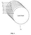
- FIG. 1 shows an ophthalmic lens having a combination of reflection and absorption coatings for selective blocking.
- FIG. 2 shows the transmission spectrum of a system according to one embodiment with selective blocking in the wavelength range of 435 nm ⁇ 10 nm.
- FIG. 3 shows the transmission spectrum of a system according to one embodiment with selective blocking in the wavelength range of 435 nm ⁇ 20 nm.
- FIG. 4 shows the transmission spectrum of a system according to one embodiment with selective blocking in the wavelength range of 435 nm ⁇ 30 nm.
- FIG. 5 shows the transmission spectrum of a system according to one embodiment with selective blocking in the wavelength range of 435 nm ⁇ 35 nm.
- FIG. 6 shows the transmission spectrum of a system with two local minima.
- FIG. 7 shows the transmission spectrum of a system with a shoulder according to one embodiment.
- FIG. 8 shows ophthalmic lens having a combination of reflection and absorption coatings for selective blocking.
- FIG. 9 shows an ophthalmic lens having a combination of reflection and absorption coatings for selective blocking.
- FIG. 10 shows an ophthalmic lens having a combination of reflection and absorption coatings for selective blocking.
- FIG. 11 shows the regions of acceptance for yellow and green traffic signals on a 1931 CIE diagram.
- FIG. 12 shows a schematic representation of wavelength regions over which average transmission values may be calculated in one embodiment of characterizing the transmission spectrum of the system.
- UVB wavelengths are from 290 nm to 320 nm
- UVA wavelengths are from 320 nm to 400 nm.
- Gamma and x-rays make up the higher frequencies of this spectrum and are absorbed by the atmosphere.
- the wavelength spectrum of ultraviolet radiation (UVR) is 100-400 nm.
- the ozone layer generally absorbs wavelengths up to 286 nm, thus shield living beings from exposure to radiation with the highest energy.
- Increased exposure to UVR has broad public health implications as an increased burden of UVR ocular and skin disease is to be expected.
- human beings are exposed to wavelengths above 286 nm, including the UVA range.
- Cataracts and macular degeneration are widely thought to result from photochemical damage to the intraocular lens and retina, respectively.
- Blue light exposure has also been shown to accelerate proliferation of uveal melanoma cells.
- the most energetic photons in the visible spectrum have wavelengths between 380 and 500 nm and are perceived as violet or blue.
- the wavelength dependence of phototoxicity summed over all mechanisms is often represented as an action spectrum, such as is described in Mainster and Sparrow, “How Much Blue Light Should an IOL Transmit?” Br. J. Ophthalmol., 2003, v. 87, pp. 1523-29 and FIG. 6 .
- In eyes without an intraocular lens aphakic eyes
- light with wavelengths shorter than 400 nm can cause damage.
- this light is absorbed by the intraocular lens and therefore does not contribute to retinal phototoxicity; however it can cause optical degradation of the lens or cataracts.
- the pupil of the eye responds to the photopic retinal illuminance, in trolands, which is the product of the incident flux with the wavelength-dependent sensitivity of the retina and the projected area of the pupil.
- This sensitivity is described in Wyszecki and Stiles, Color Science: Concepts and Methods, Quantitative Data and Formulae (Wiley: New York) 1982, esp. pages 102-107.
- the human retina includes multiple layers. These layers listed in order from the first exposed to any light entering the eye to the deepest include:
- RPE Retinal Pigment Epithelium
- a tipping point is reached when a combination of a build-up of this metabolic waste (specifically the lipofuscin fluorophore) has achieved a certain level of accumulation, the human body's physiological ability to metabolize within the retina certain of this waste has diminished as one reaches a certain age threshold, and a blue light stimulus of the proper wavelength causes drusen to be formed in the RPE layer. It is believed that the drusen then further interferes with the normal physiology/metabolic activity which allows for the proper nutrients to get to the photoreceptors thus contributing to age-related macular degeneration (AMD). AMD is the leading cause of irreversible severe visual acuity loss in the United States and Western World. The burden of AMD is expected to increase dramatically in the next 20 years because of the projected shift in population and the overall increase in the number of ageing individuals.
- AMD age-related macular degeneration
- the lighting and vision care industries have standards as to human vision exposure to UVA and UVB radiation. Surprisingly, no such standard is in place with regard to blue light.
- the glass envelope mostly blocks ultra-violet light but blue light is transmitted with little attenuation. In some cases, the envelope is designed to have enhanced transmission in the blue region of the spectrum. Such artificial sources of light hazard may also cause eye damage.
- FIG. 1 shows a system 100 including an ophthalmic lens matrix according to one embodiment.
- the system's transmission spectrum is such that the system is able to synergistically combine low overall light transmission and selective blocking of harmful blue wavelengths.
- inhibit, block, and filter mean the same.
- the average value of the transmission spectrum of system 100 is between 0% and 70%. In one embodiment, the average value is between 20% and 70%. In one embodiment, this average value is between 8% and 40%. These average transmission values allow the system to be used as a light blocking system, such as in sunglasses, car windshield, or industrial system.
- the transmission spectrum of system 100 has an average value between 0% and 30%, and preferably an average value between 5% and 30%. The transmission spectrum also has a first local minimum in its transmission at a first wavelength in the wavelength range 400 nm-470 nm.
- the lower transmission value across the wavelength range 400-470 nm and the local minimum at the first wavelength helps to maximally protect the human eye from lipofuscin accumulation and subsequent death of RPE cells.
- this system 100 is able to provide reduced overall light transmission and enhanced protection from harmful blue light wavelengths.
- the “average transmission” of a spectrum across a wavelength range is calculated by integrating the spectrum to determine the area under the transmittance curve, and dividing by the length of the wavelength range.
- the average transmission is the average height of the transmission curve, where each unit wavelength is given equal weight in calculating the average.
- the transmission spectrum has a specific value at every wavelength within the specified wavelength range.
- the transmission spectrum of the system at every wavelength across the wavelength range 470 nm to 700 nm may be between 20% and 70%.
- the system transmits from 20% to 70% of light.
- the transmission spectrum of the system at every wavelength across the wavelength range 400 nm to 470 nm is between 5% and 30%.
- the transmission spectrum of the system 100 has a first local minimum at a first wavelength in the wavelength range 400 nm-470 nm. As discussed above, this local minimum helps to enhance protection from lipofuscin accumulation and subsequent death of RPE cells.
- the local minimum of the system may be accomplished with a selective light blocking element. This may include any means of reflection, absorption, interference, and other equivalent means known. Additionally, it may be a combination of those listed.
- the transmission of the system is lower than at other wavelengths.
- One way to characterize this is by determining how much light is transmitted at the first wavelength.
- the system transmits between 0.1% and 15% of light. In another embodiment, the system transmits between 5% and 15% at the first wavelength.
- Another way to characterize the transmission spectrum at and near the first wavelength is by determining the slope of the transmission spectrum at wavelengths near the first wavelength.
- the slope of the transmission spectrum of the system is at least 0.5% transmittance per nm. This slope may be infinite (a vertical line). However, in one preferred embodiment, the slope is most 4%.
- “positive side” means on the side of the first wavelength where the wavelengths are longer than the first wavelength.
- the slope of the transmission spectrum of the system is negative but has an absolute value of at least 0.5% transmittance per nm. This slope may be infinite (a vertical line).
- the slope is at most 4%.
- negative side means on the side of the first wavelength where the wavelengths are shorter than the first wavelength.
- a system with these slope ranges may have a relatively steep and quick transition to and from the lower transmittance value at the first wavelength.
- the first average value is the average transmission of the system across a limited wavelength range that includes the first wavelength.
- the second average value is the average transmission of the system across wavelengths 400-470 nm excluding the wavelength range used to determine the first average transmission value.
- the first value is 5 to 20% less than the second value.
- a schematic representation of the two different wavelength regions is shown in FIG. 12 .
- a first average transmission near the first wavelength is determined.
- This first average value is defined as the integral of the transmission spectrum between “X” nm below the first wavelength to “X” nm above the first wavelength, divided by the two times the value of “X”.
- the value of “X” may be 5 nm, 10 nm, or 20 nm.
- this wavelength region is represented by region A where “X” is 10 nm.
- a second average transmission in the blue wavelength region is then determined. This wavelength region excludes the wavelength range used to calculate the first average transmission and is represented by only regions B and C in FIG. 12 .
- the second average transmission may be determined by taking the integral of the transmission spectrum between 400 and 470 nm and subtracting the integral of the transmission spectrum between “X” nm below the first wavelength to “X” nm above the first wavelength. The difference of these values is divided by the length in nm of the part of the transmission spectrum between 400 and 470 nm that excludes the wavelength range of “X” nm below the first wavelength to “X” nm above the first wavelength. As noted above, it is preferred that the first average transmission (1) is about 5 to 20% less than the second average transmission (2).
- the length in nm of the part of the transmission spectrum between 400 and 470 nm that excludes “X” nm below the first wavelength to “X” nm above the first wavelength is generally 50 nm, but may be greater if the first wavelength is within 10 nm of 400 nm or within 10 nm of 470 nm.
- FIGS. 2-7 show possible transmission spectra of system 100 .
- the first wavelength may be located in a variety of ranges of wavelengths within the range 400-470 nm.
- the first wavelength is within the range 425 nm to 445 nm.
- the first wavelength may be within the range 405 nm to 455 nm.
- the first wavelength may be within the range 405 nm to 465 nm.
- the first wavelength may be within the range 400 nm to 470 nm.
- the first wavelength may be within the range 435 nm to 475 nm, with the wavelength being at 455 ⁇ 10 nm, 455 ⁇ 15 nm, or 455 ⁇ 20 nm. Blocking at these ranges may reduce glare and eyestrain from LED lights or other artificial lights that may cause visual strain in this wavelength region.
- the transmission spectrum of the system 100 has only one local minimum within the wavelength range 400 nm to 470 nm. However, more than one local minimum is possible.
- the transmission spectrum of the system has a second local minimum in transmission at a second wavelength within the range 400 nm to 470 nm. The second wavelength is different from the first wavelength.
- the first and second wavelengths may be at any wavelength within the range 400 nm to 470 nm. In one embodiment, however, the first wavelength is within 15 nm of 435 nm and the second wavelength is within 15 nm of 455 nm. In one embodiment, the first and second wavelengths are at least 10 nm apart.
- the transmission spectrum of the system 100 may also have a shoulder.
- an inflection point as shown in FIGS. 4 and 7 , is indicative of a shoulder. This is, however, not in all cases.
- an inflection point includes a point where the slope turns from concave up to convex down, or vice versa. Mathematically, this may be characterized when the second derivative of the transmission spectrum changes from negative to positive or from positive to negative.
- the inflection point may occur within the wavelength ranges 400 nm to 470 nm and may be anywhere in relation to the first wavelength. However, in one embodiment, the inflection point is at a wavelength that is shorter than the first wavelength.
- Embodiments disclosed herein may be used during driving situations. Thus, they may be configured to synergistically combine elements that reduce light transmission to a level that meets international and national standards so as to be worn safely by the general public without negatively impacting proper color limits and traffic light recognition.
- one such system may be sunglasses which are popularly worn during driving.
- sunglasses worn during driving may need to meet certain standards.
- Australia introduced the world's first national standards in 1971.
- AS/NZS 1067:2003 includes five lens categories.
- Category four are designated “special purpose sunglasses” and are generally not suitable for driving.
- Category three which is suitable for driving, includes 8-18% luminous transmission and a maximum transmittance in the 280-318 nm range of 0.05 Tv, in the 315-350 nm range of 0.50 Tv, and in the 315-400 nm range of 0.50 Tv.
- Table 1 outlines the transmittance values for all five lens categories. More information regarding these categories can be found at www.arpansa.gov/au/pubs/factsheets/sunglas_brochure.pdf.
- Embodiments herein may be configured to meet the standards suitable for driving.
- Luminous max max max solar Lens transmission Transmission transmission UVA category % (Tv) 280-315 nm 315-350 nm 315-400 nm 0 80-100 0.05 Tv Tv Tv 1 43-80 0.05 Tv Tv Tv 2 18-43 0.05 Tv Tv Tv 3 8-18 0.05 TV 0.50 Tv 0.50 Tv 4 3-8 0.05 Tv 0.50 TV 0.50 Tv
- Embodiments herein may be configured so that they are suitable for driving situations through the American National Standards.
- the ANSI identifies certain characteristics that may affect the ability of the system to accurately reflect driving signs.
- Table 2 represents transmittance prosperities for nonprescription sunglasses and cosmetic lens.
- these characteristics include but are not limited to luminous transmittance of the system and traffic signal recognition of the system.
- Table 2 indicates that the luminous transmittance for general purpose lenses or shield, medium to dark, which generally represent sunglasses, have around 8-40% luminous transmittance.
- Luminous transmittance is a function of the spectral transmittance of the lens weighted by the corresponding ordinates of the photopic luminous efficiency of the 1931 CIE standard colorimetric observer and by the spectral intensity of standard illuminant C.
- Standard illuminant C represents sunlight.
- the luminous transmittance of a system can be expressed as:
- ⁇ v ⁇ 380 780 ⁇ ⁇ ⁇ ( ⁇ ) ⁇ V ⁇ ( ⁇ ) ⁇ S C ⁇ ( ⁇ ) ⁇ d ⁇ ⁇ ⁇ ⁇ 380 780 ⁇ V ⁇ ( ⁇ ) ⁇ S C ⁇ ( ⁇ ) ⁇ d ⁇ ⁇ ⁇ ⁇ ⁇
- ⁇ ( ⁇ ) is the spectral transmittance of the lens
- V( ⁇ ) is the spectral ordinate of the photopic luminous efficiency distribution of the 1931 CIE standard colorimetric observer.
- S c ( ⁇ ) is the spectral intensity of Standard Illuminant C. More information regarding this can be found in the ANSI Standards.
- the system has a luminous transmittance greater than or equal to 8% to pass standards. This luminous transmittance value is preferably as low as possible and may be as high as 100%, but is preferably at a maximum of around 40%.
- One way to determine the luminous transmittance of a lens is by a photometer that has been color corrected to produce a spectral sensitivity approximately equivalent to the spectral distribution of CIE Illuminant C as perceived by the 1931 CIE standard observer. Another way is through the visual method. This is through using an observer having normal color vision as determined by recognized color vision chart tests. The light source must have a spectral distribution approximately equivalent to CIE Illuminant C.
- Table 2 also characterizes the red, yellow, and green traffic signal transmittance that are suitable in general purpose lens.
- Traffic signal transmittance is a function of the spectral transmittance of the lens. This is then weighted by the corresponding ordinates of the phototopic luminous efficiency distribution of the 1931 CIE standard observer, the spectral intensity of Standard Illuminant A, and the spectral transmittance of the appropriate traffic signal filter (generally red, yellow, and green). This can be expressed mathematically as:
- the system has a red traffic signal transmittance greater than or equal to 8%, a yellow traffic signal transmittance greater than or equal to 6%, and a green traffic signal transmittance greater than or equal to 6%. These values are preferably as low as possible but may be as great as 100%.
- FIG. 11 indicates the regions of acceptance for the yellow and green traffic signals and average daylight as viewed through the lens for a general purpose lenses or shield, medium to dark lens. These regions of acceptance are further defined in Tables 3-5 below. Embodiments herein are configured to meet or exceed these standards.
- characteristic of the transmission spectrum at and around the first wavelength at which the first local minimum occurs or the second wavelength at which the second local minimum occurs may be incorporated by using a selective light blocking element.
- This selective light blocking element may work through one of or a combination of absorption, interference, or reflection.
- the selective blocking element may include more than one element, such as, for example, combination of one or more dyes in addition to one or more reflective layers.
- the selective light blocking element preferentially reduces light of the selected or blocked wavelengths but does not necessarily completely eliminate light of the blocked wavelengths.
- This selective light blocking element may be one of a filter, a dye, or a dielectric mirror.
- an ophthalmic lens may be dyed with a blue blocking tint, in a suitable proportion or concentration. The tinting may be accomplished, for example, by immersing the lens in a heated tint pot containing a blue blocking dye solution for some predetermined period of time. This is shown in FIG. 1 , where the dye coats 105 and 104 are placed on the lens matrix 106 in the lens system. Additionally, as shown in FIGS. 8-10 , the dyes can be located anywhere in relation to the lens matrix and other components of the system 100 .
- the selective light blocking element is one or more dyes selected or co-selected from: bilirubin; chlorophyll a, diethyl ether; chlorophyll a, methanol; chlorophyll b; diprotonated-tetraphenylporphyrin; hematin; magnesium octaethylporphyrin; magnesium octaethylporphyrin (MgOEP); magnesium phthalocyanine (MgPc), PrOH; magnesium phthalocyanine (MgPc), pyridine; magnesium tetramesitylporphyrin (MgTMP); magnesium tetraphenylporphyrin (MgTPP); octaethylporphyrin; phthalocyanine (Pc); porphin; tetra-t-butylazaporphine; tetra-t-butylnaphthalocyanine; tetrakis
- the selective light blocking element is a porphyrin or derivative thereof. Additionally, in one embodiment, the selective light blocking element is a dye containing a Soret band.
- the selective blocking element may be a filter.
- the filter could include, for example, organic or inorganic compounds exhibiting absorption and/or reflection of and/or interference with blue light wavelengths.
- the filter could comprise multiple thin layers or coatings of organic and/or inorganic substances. Each layer may have properties, which, either individually or in combination with other layers, absorbs, reflects or interferes with light having blue light wavelengths.
- Rugate notch filters are one example of blue blocking filters.
- Rugate filters are single thin films of inorganic dielectrics in which the refractive index oscillates continuously between high and low values. Fabricated by the co-deposition of two materials of different refractive index (e.g.
- rugate filters are known to have very well defined stop-bands for wavelength blocking, with very little attenuation outside the band.
- the construction parameters of the filter (oscillation period, refractive index modulation, number of refractive index oscillations) determine the performance parameters of the filter (center of the stop-band, width of the stop band, transmission within the band).
- Rugate filters are disclosed in more detail in, for example, U.S. Pat. Nos. 6,984,038 and 7,066,596, each of which is incorporated by reference in its entirety.
- Another technique is the use of multi-layer dielectric stacks. Multi-layer dielectric stacks are fabricated by depositing discrete layers of alternating high and low refractive index materials. Similarly to rugate filters, design parameters such as individual layer thickness, individual layer refractive index, and number of layer repetitions determine the performance parameters for multi-layer dielectric stacks.
- the selective light blocking element has a transmission spectrum with a third local minimum in transmission at a third wavelength.
- the third wavelength is within 35 nm of 435 nm.
- the third wavelength at which the selective light blocking element has its third local minimum is different from the first wavelength (where the system has its first local minimum). These two wavelengths are related to one another but are generally not the same. In one embodiment, however, the third wavelength and the first wavelength are the same. This is generally so when the transmission spectrum of the underlying system without the selective light blocking element may be represented by a straight line.
- the transmittance of the selective light blocking element is generally lower at the third wavelength then elsewhere.
- One way to characterize this is by comparing the transmittance of the selective light blocking element at the third wavelength with the transmittance of the selective light blocking element at other wavelengths.
- the transmission spectrum of the light blocking element has an average transmission of at least 80% across the visible spectrum, preferably 85%, and more preferably 90%.
- the third local minimum, in comparison to the average transmission, is at least 10% below that average.
- Another way to describe the characteristic of the transmission spectrum of the selective light blocking element near and at the third wavelength is by determining the slope of the transmission spectrum at wavelengths near the third wavelength.
- the slope of the transmission spectrum of the system is at least 0.5% transmittance per nm. This slope may be infinite (a vertical line). However, in one preferred embodiment, the slope is most 4%.
- the slope of the transmission spectrum of the system is negative but has an absolute value of at least 0.5% transmittance per nm. This slope may be infinite (a vertical line). However, in one preferred embodiment, the slope is most 4%.
- a selective light blocking element with these slope ranges may have a relatively steep and quick transition to and from the lower transmittance value at the first wavelength.
- the first value is the average transmission of the selective light blocking element across a narrow wavelength range that includes the third wavelength.
- the second value is the average transmission of the selective light blocking element across wavelengths 400-470 nm excluding the wavelength range used to determine the first transmission value.
- the first value is 5 to 20% less than the second value.
- a first average transmission near the third wavelength is determined.
- This first average value is defined as the integral of the transmission spectrum of the selective light blocking element between “X” nm below the third wavelength to “X” nm above the third wavelength, divided by the two times the value of “X”.
- the value of “X” may be 5 nm, 10 nm, or 20 nm.
- a second average transmission in the blue wavelength region is then determined. This wavelength region excludes the wavelength range used to calculate the first average transmission.
- the second average transmission may be determined by taking the integral of the transmission spectrum of the selective light blocking element between 400 and 470 nm and subtracting the integral of the transmission spectrum between “X” nm below the third wavelength to “X” nm above the third wavelength. The difference of these values is divided by the length in nm of the part of the transmission spectrum between 400 and 470 nm that excludes the wavelength range of “X” nm below the third wavelength to “X” nm above the third wavelength. As noted above, the first average transmission (1) is about 5 to 20% less than the second average transmission (2).
- the length in nm of the part of the transmission spectrum between 400 and 470 nm that excludes “X” nm below the first wavelength to “X” nm above the first wavelength is generally 50 nm, but may be greater if the first wavelength is within 10 nm of 400 nm or within 10 nm of 470 nm.
- Another way to characterize the transmission spectrum of the selective light blocking element at and near the third wavelength is by comparing the transmission of the system comprising the selective light blocking element to a similar system without the selective light blocking element.
- the value of the transmission spectrum of the system drops by at least 5% relative to the transmission spectrum of an otherwise similar system without the selective light blocking element. This range may be from 5% to 50%.
- the transmission spectrum of the selective light blocking element may optionally have a fourth local minimum in transmission at a fourth wavelength in the range 400 nm-470 nm.
- first”, “second”, “third, and “fourth” are arbitrary naming conventions and are not meant to represent consecutive items. Thus, for example, a “third” wavelength and a “third” minimum may exist without the existence of a “second” wavelength and a “second” minimum.
- the fourth wavelength may be at any wavelength within the wavelength range 400 nm-470 nm and is different from the third wavelength. In one embodiment, however, the third wavelength is within 15 nm of 435 nm and the fourth wavelength is within 15 nm of 455 nm. In one embodiment, additionally, the third and fourth wavelengths are within 10 nm of each other.
- the fourth wavelength and the second wavelength may or may not be the same wavelength. Generally, while they are related to each other, they are not the same. However, in one embodiment, the wavelengths are the same. This generally occurs when the transmission spectrum of the underlying system is straight.
- system 100 may comprise other filters and layers. These include antireflective coats 109 and 101 , scratch coats 107 and 103 , and ultraviolet light (UV) filters 102 and 108 . Thus, embodiments herein may optionally inhibit UV and infra-red light. Additionally, system 100 may also include at least one or a combination of an infrared filter, a photochromic dye, an anti-glare coating, an oleophobic coating, a self-cleaning coating, a self-healing coating, an anti-static film, an antimicrobial coating, a hydrophobic coating, a hardcoat primer coating, a film, or a polarizing film. Additionally, system 100 may include a color balancing component. FIG. 8 , FIG. 9 , and FIG. 10 shows systems 800 , 900 , and 1000 according to other embodiments, as already discussed above.
- Embodiments herein also include non-ophthalmic systems.
- the system instead of an ophthalmic lens, the system comprises a substrate.
- the non-ophthalmic system may be, by way of non-limiting example only: any type of windows (including building windows), automotive windshields, aircraft windows, camera flash bulbs and lenses, any type of artificial lighting fixture (either the fixture or the filament or both), fluorescent, lighting or any type of diffuser, medical instruments, surgical instruments, rifle scopes, binoculars, computer monitors, televisions screens, lighted signs or any other item or system whereby light is emitted or is transmitted or passes through filtered or unfiltered.
- an architectural window in a high-rise building may include embodiments disclosed herein in cases where reduced overall light transmission is desirable so as to reduced unwanted bright light and/or glare on occupants of the building.
- the non-ophthalmic system is in similar to system 100 in every way, except that that the average value of transmission of the system across the wavelength range 470 nm-700 nm may be lower transmission than average value of transmission of the system 100 in those wavelengths.
- the average value of the transmission spectrum of system across the wavelength range 470 nm-700 nm may between 0% and 70%, preferably between 20% and 70%, and more preferably between 5% and 70%.
- the preferable ranges for system 800 may be different from system 100 because system 800 may not be limited to certain standards for light transmittance. Additionally, the non-ophthalmic system may not need to meet the driving standards as discussed above.
- the transmission spectrum of the system 800 at every wavelength across the wavelength range 470 nm-700 nm may lower than system 100 .
- the transmission spectrum of system 800 at every wavelength across the wavelength range 470 nm-700 nm may be between 20% and 70%, preferably between 5% and 70%.
- the non-ophthalmic system may also comprise a selective light blocking element that is similar to the selective blocking element described above.
- references herein to “one embodiment,” “an embodiment,” “an example embodiment,” or similar phrases indicate that the embodiment described may include a particular feature, structure, or characteristic, but every embodiment may not necessarily include the particular feature, structure, or characteristic. Moreover, such phrases are not necessarily referring to the same embodiment. Further, when a particular feature, structure, or characteristic is described in connection with an embodiment, it would be within the knowledge of persons skilled in the relevant art(s) to incorporate such feature, structure, or characteristic into other embodiments whether or not explicitly mentioned or described herein. The breadth and scope of the invention should not be limited by any of the above-described exemplary embodiments, but should be defined only in accordance with the following claims and their equivalents.
Abstract
A system is provided that selectively blocks blue light in addition to having low overall transmittance values. The average value of the transmission spectrum of the system across the wavelength range 400 nm-470 nm is between 0% and 30% and the average value of the transmission spectrum across the wavelength range 470 nm-700 nm is between 0% and 70%. The transmission spectrum of the system has a first local minimum in transmission between 400 nm-470 nm.
Description
The present application claims benefit to U.S. Provisional Application No. 61/991,721, filed on May 12, 2014, which is related to U.S. Provisional Application No. 61/819,599, filed on May 5, 2013. The contents of these applications are expressly incorporated herein by reference in their entireties. Additionally, the following applications and patents are related to the application herein: U.S. Pat. Nos. 7,556,376; 7,520,608; 8,360, 574; 8,403,478; Ser. Nos. 13/770,517; 12/080,806; U.S. Pat. Nos. 7,066,596; 6,984,038; 7,029,118.
Field of the Invention
The present invention relates to systems having low overall light transmission in addition to enhanced blocking of selective wavelengths.
Background Art
Electromagnetic radiation from the sun continuously bombards the Earth's atmosphere. Light is made up of electromagnetic radiation that travels in waves. The electromagnetic spectrum includes radio waves, millimeter waves, microwaves, infrared, visible light, ultra-violet (UVA and UVB), x-rays, and gamma rays. The visible light spectrum includes the longest visible light wavelength of approximately 700 nm and the shortest of approximately 400 nm (nanometers or 10-9 meters).
In one embodiment, an ophthalmic system has an ophthalmic lens. The average value of the transmission spectrum of the system across the wavelength range 400 nm-470 nm is between 0% and 30%. The average value of the transmission spectrum of the system across the wavelength range 470 nm-700 nm is between 0% and 70%. The transmission spectrum of the system has a first local minimum in transmission at a first wavelength in the wavelength range 400 nm-470 nm. In one embodiment, the average value of the transmission spectrum of the system across the wavelength range 400 nm-470 nm is between 5% and 30% and the average value of the transmission spectrum of the system across the wavelength range 470 nm-700 nm is between 20% and 70%.
In one embodiment, the transmission spectrum of the system at every wavelength across the wavelength range 400 nm to 470 nm is between 5% and 30%. In one embodiment, the transmission spectrum of the system at every wavelength across the wavelength range 470 nm to 700 nm is between 20% and 70%.
In one embodiment, the average value of the transmission spectrum of the system across the wavelength range 470 nm to 700 nm is between 8% and 40%.
In one embodiment, for least one point within 10 nm of the first wavelength on the positive side, the slope of the transmission spectrum of the system is at least 0.5% transmittance per nm. In one embodiment, for at least one point within 10 nm of the first wavelength on the negative side, the slope of the transmission spectrum of the system is negative and has an absolute value of at least 0.5% transmittance per nm.
In one embodiment, at the first wavelength, the system transmits between 0.1% and 15%. In one embodiment, at the first wavelength, the system transmits between 5% and 15%.
In one embodiment, the first wavelength is within the range 425 nm to 445 nm. In one embodiment, the first wavelength is within the range 405 nm to 455 nm. In one embodiment, the first wavelength is within the range 405 nm to 465 nm. In one embodiment, the first wavelength is within the range 440 nm to 470 nm.
In one embodiment, the transmission spectrum of the system has only one local minimum within the wavelength range 400 nm to 470 nm.
In one embodiment, the transmission spectrum of the system has a first average transmission near the first wavelength. The first average transmission is defined as the integral of the transmission spectrum between 5 nm below the first wavelength to 5 nm above the first wavelength, divided by 10 nm. The transmission spectrum of the system has a second average transmission in the blue region excluding wavelength range used to calculate the first average transmission. The second average transmission is defined as the integral of the transmission spectrum between 400 and 470 nm minus the integral of the transmission spectrum between 5 nm below the first wavelength to 5 nm above the first wavelength, divided by the length in nm of the part of the transmission spectrum between 400 and 470 nm that excludes 5 nm below the first wavelength to 5 nm above the first wavelength. The first average transmission is 5 to 20% less than the second average transmission.
In one embodiment, the transmission spectrum of the system has a first average transmission near the first wavelength. The first average transmission is defined as the integral of the transmission spectrum between 10 nm below the first wavelength to 10 nm above the first wavelength, divided by 20 nm. The transmission spectrum of the system has a second average transmission in the blue region excluding wavelength range used to calculate the first average transmission. The second average transmission is defined as the integral of the transmission spectrum between 400 and 470 nm minus the integral of the transmission spectrum between 10 nm below the first wavelength to 10 nm above the first wavelength, divided by the length in nm of the part of the transmission spectrum between 400 and 470 nm that excludes 10 nm below the first wavelength to 10 nm above the first wavelength. The first average transmission is 5 to 20% less than the second average transmission.
In one embodiment, the transmission spectrum of the system has a first average transmission near the first wavelength. The first average transmission is defined as the integral of the transmission spectrum between 20 nm below the first wavelength to 20 nm above the first wavelength, divided by 40 nm. The transmission spectrum of the system has a second average transmission in the blue region excluding wavelength range used to calculate the first average transmission. The second average transmission is defined as the integral of the transmission spectrum between 400 and 470 nm minus the integral of the transmission spectrum between 20 nm below the first wavelength to 20 nm above the first wavelength, divided by the length in nm of the part of the transmission spectrum between 400 and 470 nm that excludes 20 nm below the first wavelength to 20 nm above the first wavelength. The first average transmission is 5 to 20% less than the second average transmission.
In one embodiment, the transmission spectrum of the system further comprises at least one inflection point at a wavelength lower than the first wavelength.
In one embodiment, the transmission spectrum of the system has a second local minimum in transmission at a second wavelength in the range 400 nm-470 nm. The second wavelength is different from the first wavelength. In one embodiment, the first wavelength is within 15 nm of 435 nm and the second wavelength is within 15 nm of 455 nm. In one embodiment, the first and second wavelengths are at least 10 nm apart.
In one embodiment, the system has a luminous transmittance greater than or equal to 8%. In one embodiment, the system has a red traffic signal transmittance greater than or equal to 8%, a yellow traffic signal transmittance greater than or equal to 6%, and a green traffic signal transmittance greater than or equal to 6%.
In one embodiment, the system comprises a selective light blocking element having a transmission spectrum.
In one embodiment, the transmission spectrum of the light blocking element has a third local minimum in transmission at a third wavelength. The third wavelength is within 35 nm of 435 nm.
In one embodiment, the transmission spectrum of the light blocking element has an average transmission of at least 80% across the visible spectrum, and the third local minimum is at least 10% below the average transmission of the light blocking element across the visible spectrum. In one embodiment, the transmission spectrum of the light blocking element has an average transmission of at least 85% across the visible spectrum, and the third local minimum is at least 10% below the average transmission of the light blocking element across the visible spectrum. In one embodiment, the transmission spectrum of the light blocking element has an average transmission of at least 90% across the visible spectrum, and the third local minimum is at least 10% below the average transmission of the light blocking element across the visible spectrum.
In one embodiment, the transmission spectrum of the selective light blocking element has a fourth local minimum in transmission at a fourth wavelength in the range 400 nm-470 nm. The fourth wavelength is different from the third wavelength.
In one embodiment, the third wavelength is within 15 nm of 435 nm and the fourth wavelength is within 15 nm of 455 nm. In one embodiment, the third and fourth wavelengths are within 10 nm of each other.
In one embodiment, for at least one point within 10 nm of the third wavelength on the positive side, the slope of the transmission spectrum of the selective light blocking element is at least 0.5% transmittance per nm. In one embodiment, for at least one point within 10 nm of the third wavelength on the negative side, the slope of the transmission spectrum of the selective light blocking element is negative and has an absolute value of at least 0.5% transmittance per nm.
In one embodiment, transmission spectrum of the selective light blocking element has a first average transmission near the third wavelength defined as the integral of the transmission spectrum of the selective light blocking element between 5 nm below the third wavelength to 5 nm above the third wavelength, divided by 10 nm. The transmission spectrum of the selective light blocking element has a second average transmission in the blue region excluding wavelength range used to calculate the first average transmission. The second average transmission is defined as the integral of the transmission spectrum of the light blocking element between 400 and 470 nm minus the integral of the transmission spectrum between 5 nm below the third wavelength to 5 nm above the third wavelength, divided by the length in nm of the part of the transmission spectrum of the light blocking element between 400 and 470 nm that excludes 5 nm below the third wavelength to 5 nm above the third wavelength. The first average transmission is 5 to 20% less than the second average transmission.
In one embodiment, transmission spectrum of the selective light blocking element has a first average transmission near the third wavelength defined as the integral of the transmission spectrum of the selective light blocking element between 10 nm below the third wavelength to 10 nm above the third wavelength, divided by 20 nm. The transmission spectrum of the selective light blocking element has a second average transmission in the blue region excluding wavelength range used to calculate the first average transmission. The second average transmission is defined as the integral of the transmission spectrum of the light blocking element between 400 and 470 nm minus the integral of the transmission spectrum between 10 nm below the third wavelength to 10 nm above the third wavelength, divided by the length in nm of the part of the transmission spectrum of the light blocking element between 400 and 470 nm that excludes 10 nm below the third wavelength to 10 nm above the third wavelength. The first average transmission is 5 to 20% less than the second average transmission.
In one embodiment, transmission spectrum of the selective light blocking element has a first average transmission near the third wavelength defined as the integral of the transmission spectrum of the selective light blocking element between 20 nm below the third wavelength to 20 nm above the third wavelength, divided by 40 nm. The transmission spectrum of the selective light blocking element has a second average transmission in the blue region excluding wavelength range used to calculate the first average transmission. The second average transmission is defined as the integral of the transmission spectrum of the light blocking element between 400 and 470 nm minus the integral of the transmission spectrum between 20 nm below the third wavelength to 20 nm above the third wavelength, divided by the length in nm of the part of the transmission spectrum of the light blocking element between 400 and 470 nm that excludes 20 nm below the third wavelength to 20 nm above the third wavelength. The first average transmission is 5 to 20% less than the second average transmission.
In one embodiment, the transmission spectrum of the selective blocking element only has one local minimum within the wavelength range 400 nm to 470 nm. In one embodiment, the value of the transmission spectrum of the system drops by at least 5% relative to an otherwise equivalent system without the selective light blocking element at the third wavelength.
In one embodiment, the selective light blocking element is one of or a combination of a dye or a dielectric mirror. In one embodiment, the selective light blocking element comprises a rugate filter.
In one embodiment, the selective blocking element is one or more dyes selected or co-selected from: bilirubin; chlorophyll a, diethyl ether; chlorophyll a, methanol; chlorophyll b; diprotonated-tetraphenylporphyrin; hematin; magnesium octaethylporphyrin; magnesium octaethylporphyrin (MgOEP); magnesium phthalocyanine (MgPc), PrOH; magnesium phthalocyanine (MgPc), pyridine; magnesium tetramesitylporphyrin (MgTMP); magnesium tetraphenylporphyrin (MgTPP); octaethylporphyrin; phthalocyanine (Pc); porphin; tetra-t-butylazaporphine; tetra-t-butylnaphthalocyanine; tetrakis(2,6-dichlorphenyl)porphyrin; tetrakis(o-aminophenyl)porphyrin; tetramesitylporphyrin (TMP); tetraphenylporphyrin (TPP); vitamin B12; zinc octaethylporphyrin (ZnOEP); zinc phthalocyanine (ZnPc), pyridine; zinc tetramesitylporphyrin (ZnTMP); zinc tetramesitylporphyrin radical cation; zinc tetrapheynlporphyrin (ZnTPP); Manganese(III) 5,10,15,20-tetra(4-pyridyl)-21H,23H-porphine chloride tetrakis(metho chloride)-10,15,20-Tetrakis(4-sulfonatophenyl)-21H,23H-porphine manganese(III) chloride, 2,3,7,8,12,13,17,18-Octaethyl-21H,23H-porphine manganese(III) chloride, Meso-tetra(N-methyl-4-pyridyl)porphine tetra chloride dihydrochloride, Meso-tetra(N-methyl-4-pyridyl)porphine tetra chloride dihydrochloride, Mn(III) meso-tetra(N-methyl-4-pyridyl)porphine pentachloride, Mn(III) meso-tetraphenylporphine chloride, palladium(II)-meso-tetra(4-fluorophenyl)tetrabenzoporphyrin (PdTPTBPF), palladium(II)-meso-tetraphenyltetranaphthoporphyrin (PdTPTNP), platinum(II)-meso-tetra(4-fluorophenyl)tetrabenzoporphyrin (PtTPTBPF), platinum(II)-meso-tetraphenyltetranaphthoporphyrin (PtTPTNP), zinc tetrakis(arylethynyl)porphyrins, perylene and derivatives thereof.
In one embodiment, the selective light blocking element is a porphyrin or derivative thereof. In one embodiment, the selective light blocking element is a dye containing a Soret band.
In one embodiment, the ophthalmic system includes an ultraviolet light filter. In on embodiment, the ophthalmic system includes an infrared filter. In one embodiment, the system further includes a photochromic dye. In one embodiment, the system comprises at least one of or a combination of a dielectric coating, a hydrophobic coating, an antireflective coating, a rugate filter, a hardcoat primer coating, a film, or a polarizing film. In one embodiment, the system comprises at least one of or a combination of a UV blocking component, an optional IR blocking component, an anti-glare coating, an anti-reflective coating, an oleophobic coating, a self-cleaning coating, a self-healing coating, an anti-static film, an antimicrobial coating, or a scratch-resistant coating.
In one embodiment, a system comprises a substrate. The average value of the transmission spectrum of the system across the wavelength range 400 nm-470 nm is between 0% and 30%. The average value of the transmission spectrum of the system across the wavelength range 470 nm-700 nm is between 0% and 70%. The transmission spectrum of the system has a first local minimum in transmission at a first wavelength in the wavelength range 400 nm-470 nm.
In one embodiment, the system transmits filtered or unfiltered light to the human eye. In one embodiment, the system is not an ophthalmic lens or system. In one embodiment, the system is selected from a group consisting of: window, automotive windshield, camera flash bulb and lens, artificial lighting fixture, fluorescent, lighting or diffuser, medical instrument, surgical instrument, rifle scope, binoculars, computer monitor, television screen, lighted signs, and patio fixture. X
In one embodiment, the average value of the transmission spectrum of the system across the wavelength range 400 nm-470 nm is between 5% and 30%. The average value of the transmission spectrum of the system across the wavelength range 470 nm-700 nm is between 5% and 70%.
In one embodiment, the transmission spectrum of the system at every wavelength across the wavelength range 400 nm to 470 nm is between 5% and 30%. In one embodiment, the transmission spectrum of the system at every wavelength across the wavelength range 470 nm to 700 nm is between 5% and 70%.
In one embodiment, the average value of the transmission spectrum of the system across the wavelength range 470 nm to 700 nm is between 8% and 40%.
In one embodiment, for at least one point within 10 nm of the first wavelength on the positive side, the slope of the transmission spectrum of the system is at least 0.5-4% transmittance per nm. In one embodiment, for at least one point within 10 nm of the first wavelength on the negative side, the slope of the transmission spectrum of the system is negative and has an absolute value of at least 0.5-4% transmittance per nm.
In one embodiment, at the first wavelength, the system transmits between 0.1% and 15%. In one embodiment, at the first wavelength, the system transmits between 5% and 15%.
In one embodiment, the first wavelength is within the wavelength range 425 nm to 445 nm. In one embodiment, the first wavelength is within the wavelength range 405 nm to 455 nm. In one embodiment, the first wavelength is within the wavelength range 405 nm to 465 nm. In one embodiment, the first wavelength is within the wavelength range 440 nm to 470 nm.
In one embodiment, the transmission spectrum of the system has only one local minimum within the wavelength range 400 nm to 470 nm.
In one embodiment, the transmission spectrum of the system has a first average transmission near the first wavelength. The first average transmission is defined as the integral of the transmission spectrum between 5 nm below the first wavelength to 5 nm above the first wavelength, divided by 10 nm. The transmission spectrum of the system has a second average transmission in the blue region excluding wavelength range used to calculate the first average transmission. The second average transmission is defined as the integral of the transmission spectrum between 400 and 470 nm minus the integral of the transmission spectrum between 5 nm below the first wavelength to 5 nm above the first wavelength, divided by the length in nm of the part of the transmission spectrum between 400 and 470 nm that excludes 5 nm below the first wavelength to 5 nm above the first wavelength. The first average transmission is 5 to 20% less than the second average transmission.
In one embodiment, the transmission spectrum of the system has a first average transmission near the first wavelength. The first average transmission is defined as the integral of the transmission spectrum between 10 nm below the first wavelength to 10 nm above the first wavelength, divided by 20 nm. The transmission spectrum of the system has a second average transmission in the blue region excluding wavelength range used to calculate the first average transmission. The second average transmission is defined as the integral of the transmission spectrum between 400 and 470 nm minus the integral of the transmission spectrum between 10 nm below the first wavelength to 10 nm above the first wavelength, divided by the length in nm of the part of the transmission spectrum between 400 and 470 nm that excludes 10 nm below the first wavelength to 10 nm above the first wavelength. The first average transmission is 5 to 20% less than the second average transmission.
In one embodiment, the transmission spectrum of the system has a first average transmission near the first wavelength. The first average transmission is defined as the integral of the transmission spectrum between 20 nm below the first wavelength to 20 nm above the first wavelength, divided by 40 nm. The transmission spectrum of the system has a second average transmission in the blue region excluding wavelength range used to calculate the first average transmission. The second average transmission is defined as the integral of the transmission spectrum between 400 and 470 nm minus the integral of the transmission spectrum between 20 nm below the first wavelength to 20 nm above the first wavelength, divided by the length in nm of the part of the transmission spectrum between 400 and 470 nm that excludes 20 nm below the first wavelength to 20 nm above the first wavelength. The first average transmission is 5 to 20% less than the second average transmission.
In one embodiment, the transmission spectrum of the system further comprises at least one inflection point at a wavelength lower than the first wavelength.
In one embodiment, the transmission spectrum of the system has a second local minimum in transmission at a second wavelength in the wavelength range 400 nm-470 nm. The second wavelength is different from the first wavelength.
In one embodiment, the first wavelength is within 15 nm of 435 nm and the second wavelength is within 15 nm of 455 nm. In one embodiment, the first and second wavelengths are within 10 nm of each other.
In one embodiment, the system includes a selective light blocking element having a transmission spectrum. In one embodiment, the transmission spectrum of the selective light blocking element has a third local minimum in transmission at a third wavelength; wherein the wavelength is within 35 nm of 435 nm.
In one embodiment, the transmission spectrum of the selective light blocking element has an average transmission of at least 80% across the visible spectrum, and the third local minimum is at least 10% below the average transmission of the light blocking element across the visible spectrum.
In one embodiment, the transmission spectrum of the light blocking element has an average transmission of at least 85% across the visible spectrum, and the third local minimum is at least 10% below the average transmission of the light blocking element across the visible spectrum.
In one embodiment, the transmission spectrum of the light blocking element has an average transmission of at least 90% across the visible spectrum, and the third local minimum is at least 10% below the average transmission of the light blocking element across the visible spectrum.
In one embodiment, the transmission spectrum of the selective light blocking element has a fourth local minimum in transmission at a fourth wavelength in the wavelength range 400 nm-470 nm. The fourth wavelength is different from the third wavelength.
In one embodiment, the third wavelength is within 15 nm of 435 nm and is the fourth wavelength is within 15 nm of 455 nm. In one embodiment, the third and fourth wavelengths are within 10 nm of each other.
In one embodiment, for at least one point within 10 nm of the third wavelength on the positive side, the slope of the transmission spectrum is at least 0.5% transmittance per nm. In one embodiment, for at least one point within 10 nm of the third wavelength on the negative side, the slope of the transmission spectrum is negative and has an absolute value of at least 0.5% transmittance per nm.
In one embodiment, transmission spectrum of the selective light blocking element has a first average transmission near the third wavelength defined as the integral of the transmission spectrum of the selective light blocking element between 5 nm below the third wavelength to 5 nm above the third wavelength, divided by 10 nm. The transmission spectrum of the selective light blocking element has a second average transmission in the blue region excluding wavelength range used to calculate the first average transmission. The second average transmission is defined as the integral of the transmission spectrum of the light blocking element between 400 and 470 nm minus the integral of the transmission spectrum between 5 nm below the third wavelength to 5 nm above the third wavelength, divided by the length in nm of the part of the transmission spectrum of the light blocking element between 400 and 470 nm that excludes 5 nm below the third wavelength to 5 nm above the third wavelength. The first average transmission is 5 to 20% less than the second average transmission.
In one embodiment, transmission spectrum of the selective light blocking element has a first average transmission near the third wavelength defined as the integral of the transmission spectrum of the selective light blocking element between 10 nm below the third wavelength to 10 nm above the third wavelength, divided by 20 nm. The transmission spectrum of the selective light blocking element has a second average transmission in the blue region excluding wavelength range used to calculate the first average transmission. The second average transmission is defined as the integral of the transmission spectrum of the light blocking element between 400 and 470 nm minus the integral of the transmission spectrum between 10 nm below the third wavelength to 10 nm above the third wavelength, divided by the length in nm of the part of the transmission spectrum of the light blocking element between 400 and 470 nm that excludes 10 nm below the third wavelength to 10 nm above the third wavelength. The first average transmission is 5 to 20% less than the second average transmission.
In one embodiment, transmission spectrum of the selective light blocking element has a first average transmission near the third wavelength defined as the integral of the transmission spectrum of the selective light blocking element between 20 nm below the third wavelength to 20 nm above the third wavelength, divided by 40 nm. The transmission spectrum of the selective light blocking element has a second average transmission in the blue region excluding wavelength range used to calculate the first average transmission. The second average transmission is defined as the integral of the transmission spectrum of the light blocking element between 400 and 470 nm minus the integral of the transmission spectrum between 20 nm below the third wavelength to 20 nm above the third wavelength, divided by the length in nm of the part of the transmission spectrum of the light blocking element between 400 and 470 nm that excludes 20 nm below the third wavelength to 20 nm above the third wavelength. The first average transmission is 5 to 20% less than the second average transmission.
In one embodiment, the transmission spectrum of the selective light blocking element has only one local minimum within the wavelength range 400 nm to 470 nm.
In one embodiment, the value of the transmission spectrum of the system drops by at least 5% relative to an otherwise equivalent system without the selective light blocking element at the third wavelength.
In one embodiment, the transmission spectrum of the selective light blocking element only has one local minimum within the wavelength range 400 nm to 470 nm.
In one embodiment, the selective light blocking element is one of or a combination of a dye or a dielectric mirror.
In one embodiment, the selective light blocking element comprises a rugate filter.
In one embodiment, the selective blocking element is one or more dyes selected or co-selected from: bilirubin; chlorophyll a, diethyl ether; chlorophyll a, methanol; chlorophyll b; diprotonated-tetraphenylporphyrin; hematin; magnesium octaethylporphyrin; magnesium octaethylporphyrin (MgOEP); magnesium phthalocyanine (MgPc), PrOH; magnesium phthalocyanine (MgPc), pyridine; magnesium tetramesitylporphyrin (MgTMP); magnesium tetraphenylporphyrin (MgTPP); octaethylporphyrin; phthalocyanine (Pc); porphin; tetra-t-butylazaporphine; tetra-t-butylnaphthalocyanine; tetrakis(2,6-dichlorphenyl)porphyrin; tetrakis(o-aminophenyl)porphyrin; tetramesitylporphyrin (TMP); tetraphenylporphyrin (TPP); vitamin B12; zinc octaethylporphyrin (ZnOEP); zinc phthalocyanine (ZnPc), pyridine; zinc tetramesitylporphyrin (ZnTMP); zinc tetramesitylporphyrin radical cation; zinc tetrapheynlporphyrin (ZnTPP); Manganese(III) 5,10,15,20-tetra(4-pyridyl)-21H,23H-porphine chloride tetrakis(metho chloride)-10,15,20-Tetrakis(4-sulfonatophenyl)-21H,23H-porphine manganese(III) chloride, 2,3,7,8,12,13,17,18-Octaethyl-21H,23H-porphine manganese(III) chloride, Meso-tetra(N-methyl-4-pyridyl)porphine tetra chloride dihydrochloride, Meso-tetra(N-methyl-4-pyridyl)porphine tetra chloride dihydrochloride, Mn(III) meso-tetra(N-methyl-4-pyridyl)porphine pentachloride, Mn(III) meso-tetraphenylporphine chloride, palladium(II)-meso-tetra(4-fluorophenyl)tetrabenzoporphyrin (PdTPTBPF), palladium(II)-meso-tetraphenyltetranaphthoporphyrin (PdTPTNP), platinum(II)-meso-tetra(4-fluorophenyl)tetrabenzoporphyrin (PtTPTBPF), platinum(II)-meso-tetraphenyltetranaphthoporphyrin (PtTPTNP), zinc tetrakis(arylethynyl)porphyrins, perylene and derivatives thereof.
In one embodiment, the selective light blocking element is a porphyrin dye or derivative thereof.
In one embodiment, the selective light blocking element is a dye containing a Soret band.
In one embodiment, the system further includes an ultraviolet light filter.
In one embodiment, the system further includes an infrared filter.
In one embodiment, the system further includes a photochromic dye.
In one embodiment, the system comprises at least one of or a combination of a dielectric coating, a hydrophobic coating, an antireflective coating, a rugate filter, a hardcoat primer coating, a film, or a polarizing film.
In one embodiment, the system comprises at least one of or a combination of a UV blocking component, an optional IR blocking component, an anti-glare coating, an anti-reflective coating, an oleophobic coating, a self-cleaning coating, a self-healing coating, an anti-static film, an antimicrobial coating, or a scratch-resistant coating.
Blue light wavelengths fall in the approximate range of 400 nm to 500 nm. For the ultra-violet bands, UVB wavelengths are from 290 nm to 320 nm, and UVA wavelengths are from 320 nm to 400 nm. Gamma and x-rays make up the higher frequencies of this spectrum and are absorbed by the atmosphere. The wavelength spectrum of ultraviolet radiation (UVR) is 100-400 nm.
While the human retina responds only to the visible light portion of the electromagnetic spectrum, all wavelengths have the capability to damage the eye. The ozone layer generally absorbs wavelengths up to 286 nm, thus shield living beings from exposure to radiation with the highest energy. However, over the last 20 years, there has been documented depletion of the ozone layer primarily due to industrial pollution. Increased exposure to UVR has broad public health implications as an increased burden of UVR ocular and skin disease is to be expected. Additionally, human beings are exposed to wavelengths above 286 nm, including the UVA range. Thus, it is desirable for systems that transmit light to the eye to have additional shielding from these wavelengths in order to enhance the protection given by the ozone layer.
Many of the wavelengths above 286 nm fall within the human visual spectrum (400-700 nm). The shorter wavelengths of the visible spectrum pose the greatest hazard because they inversely contain more energy. Blue light has been shown to be the portion of the visible spectrum that produces the most photochemical damage to animal retinal pigment epithelium (RPE) cells. Exposure to these wavelengths has been called the blue light hazard because these wavelengths are perceived as blue by the human eye.
Cataracts and macular degeneration are widely thought to result from photochemical damage to the intraocular lens and retina, respectively. Blue light exposure has also been shown to accelerate proliferation of uveal melanoma cells. The most energetic photons in the visible spectrum have wavelengths between 380 and 500 nm and are perceived as violet or blue. The wavelength dependence of phototoxicity summed over all mechanisms is often represented as an action spectrum, such as is described in Mainster and Sparrow, “How Much Blue Light Should an IOL Transmit?” Br. J. Ophthalmol., 2003, v. 87, pp. 1523-29 and FIG. 6 . In eyes without an intraocular lens (aphakic eyes), light with wavelengths shorter than 400 nm can cause damage. In phakic eyes, this light is absorbed by the intraocular lens and therefore does not contribute to retinal phototoxicity; however it can cause optical degradation of the lens or cataracts.
The pupil of the eye responds to the photopic retinal illuminance, in trolands, which is the product of the incident flux with the wavelength-dependent sensitivity of the retina and the projected area of the pupil. This sensitivity is described in Wyszecki and Stiles, Color Science: Concepts and Methods, Quantitative Data and Formulae (Wiley: New York) 1982, esp. pages 102-107.
Current research strongly supports the premise that short wavelength visible light (blue light) having a wavelength of approximately 400 nm-500 nm could be a contributing cause of AMD (age related macular degeneration). It is believed that the highest level of blue light absorption occurs in a region around 430-435 nm, such as 400 nm-460 nm. Research further suggests that blue light worsens other causative factors in AMD, such as heredity, tobacco smoke, and excessive alcohol consumption.
The human retina includes multiple layers. These layers listed in order from the first exposed to any light entering the eye to the deepest include:
1) Nerve Fiber Layer
2) Ganglion Cells
3) Inner Plexiform Layer
4) Bipolar and Horizontal Cells
5) Outer Plexiform Layer
6) Photoreceptors (Rods and Cones)
7) Retinal Pigment Epithelium (RPE)
8) Bruch's Membrane
9) Choroid
When light is absorbed by the eye's photoreceptor cells, (rods and cones) the cells bleach and become unreceptive until they recover. This recovery process is a metabolic process and is called the “visual cycle.” Absorption of blue light has been shown to reverse this process prematurely. The function of the RPE is to provide nourishment to the retina's photoreceptors. The premature reversal increases the risk of oxidative damage and is believed to lead to the buildup of the pigment lipofuscin in the retina. This build up occurs in the retinal pigment epithelium (RPE) layer and interferes with its ability to provide nourishment. It is believed that aggregates of extra-cellular materials called drusen are formed due to the excessive amounts of lipofuscin.
Current research indicates that over the course of one's life, beginning with that of an infant, metabolic waste byproducts accumulate within the RPE, due to light interactions with the retina. This metabolic waste product is characterized by certain fluorophores, one of the most prominent being lipofuscin constituent A2E. In vitro studies by Sparrow indicate that lipofuscin chromophore A2E found within the RPE is maximally excited by 430-435 nm light. It is theorized that a tipping point is reached when a combination of a build-up of this metabolic waste (specifically the lipofuscin fluorophore) has achieved a certain level of accumulation, the human body's physiological ability to metabolize within the retina certain of this waste has diminished as one reaches a certain age threshold, and a blue light stimulus of the proper wavelength causes drusen to be formed in the RPE layer. It is believed that the drusen then further interferes with the normal physiology/metabolic activity which allows for the proper nutrients to get to the photoreceptors thus contributing to age-related macular degeneration (AMD). AMD is the leading cause of irreversible severe visual acuity loss in the United States and Western World. The burden of AMD is expected to increase dramatically in the next 20 years because of the projected shift in population and the overall increase in the number of ageing individuals.
Drusen hinders or blocks the RPE layer from providing the proper nutrients to the photoreceptors, which leads to damage or even death of these cells. To further complicate this process, it appears that when lipofuscin absorbs blue light in high quantities it becomes toxic, causing further damage and/or death of the RPE cells. It is believed that the lipofuscin constituent A2E is at least partly responsible for the short-wavelength sensitivity of RPE cells. A2E has been shown to be maximally excited by blue light; the photochemical events resulting from such excitation can lead to cell death. See, for example, Janet R. Sparrow et al., “Blue light-absorbing intraocular lens and retinal pigment epithelium protection in vitro,” J. Cataract Refract. Surg. 2004, vol. 30, pp. 873-78.
From a theoretical perspective, the following appears to take place:
-
- 1) Waste buildup occurs within the pigment epithelial level starting from infancy throughout life.
- 2) Retinal metabolic activity and ability to deal with this waste typically diminish with age.
- 3) The macula pigment typically decreases as one ages, thus filtering out less blue light.
- 4) Blue light causes the lipofuscin to become toxic. The resulting toxicity damages pigment epithelial cells.
The lighting and vision care industries have standards as to human vision exposure to UVA and UVB radiation. Surprisingly, no such standard is in place with regard to blue light. For example, in the common fluorescent tubes available today, the glass envelope mostly blocks ultra-violet light but blue light is transmitted with little attenuation. In some cases, the envelope is designed to have enhanced transmission in the blue region of the spectrum. Such artificial sources of light hazard may also cause eye damage.
Laboratory evidence by Sparrow at Columbia University has shown that if about 50% of the blue light within the wavelength range of 430±30 nm is blocked, RPE cell death caused by the blue light may be reduced by up to 80%.
Thus, it is desirable to have light transmitting systems that selectively block the harmful range of blue light. Many systems such as sunglasses and tinted windows provide overall reduced light transmission to protect the human eye from UV and visible light but do not selectively block this damaging range of blue light. Thus, there is a need for systems that provide synergistic combination of UV protection, reduced overall light transmission, and selective blocking in the 400-470 nm range. Additionally, it is desirable that these systems meet specific color transmission standards when intended to be used in certain driving conditions.
Across the wavelength range of 470 nm-700 nm, the average value of the transmission spectrum of system 100 is between 0% and 70%. In one embodiment, the average value is between 20% and 70%. In one embodiment, this average value is between 8% and 40%. These average transmission values allow the system to be used as a light blocking system, such as in sunglasses, car windshield, or industrial system. Across the wavelength range 400 nm-470 nm, however, the transmission spectrum of system 100 has an average value between 0% and 30%, and preferably an average value between 5% and 30%. The transmission spectrum also has a first local minimum in its transmission at a first wavelength in the wavelength range 400 nm-470 nm. The lower transmission value across the wavelength range 400-470 nm and the local minimum at the first wavelength helps to maximally protect the human eye from lipofuscin accumulation and subsequent death of RPE cells. Thus, this system 100 is able to provide reduced overall light transmission and enhanced protection from harmful blue light wavelengths.
As used herein, the “average transmission” of a spectrum across a wavelength range is calculated by integrating the spectrum to determine the area under the transmittance curve, and dividing by the length of the wavelength range. In other words, the average transmission is the average height of the transmission curve, where each unit wavelength is given equal weight in calculating the average. Where a range for “average transmission” across a wavelength range is claimed or described, the transmission at individual wavelength points within the wavelength range may be higher or lower than the claimed range for the average, so long as the average itself falls within the claimed range. So, for example, a spectrum having a transmission of 90% at most wavelengths in a wavelength range, but a transmission of 50% at just a few wavelengths in the wavelength range, would have an “average transmission” above 80% across the wavelength range because the calculation described above would result in a number close to 90%, notwithstanding the fact that the transmission at a few points is well below 80%.
In one embodiment, instead of being an average value across the specified wavelength range, the transmission spectrum has a specific value at every wavelength within the specified wavelength range. For example, the transmission spectrum of the system at every wavelength across the wavelength range 470 nm to 700 nm may be between 20% and 70%. Thus, at every wavelength in the range 470 nm to 700 nm, the system transmits from 20% to 70% of light. Additionally, in one embodiment, the transmission spectrum of the system at every wavelength across the wavelength range 400 nm to 470 nm is between 5% and 30%.
In one embodiment, the transmission spectrum of the system 100 has a first local minimum at a first wavelength in the wavelength range 400 nm-470 nm. As discussed above, this local minimum helps to enhance protection from lipofuscin accumulation and subsequent death of RPE cells. The local minimum of the system may be accomplished with a selective light blocking element. This may include any means of reflection, absorption, interference, and other equivalent means known. Additionally, it may be a combination of those listed.
Generally, at this first wavelength, the transmission of the system is lower than at other wavelengths. One way to characterize this is by determining how much light is transmitted at the first wavelength. In one embodiment, at the first wavelength where the local minimum occurs, the system transmits between 0.1% and 15% of light. In another embodiment, the system transmits between 5% and 15% at the first wavelength.
Another way to characterize the transmission spectrum at and near the first wavelength is by determining the slope of the transmission spectrum at wavelengths near the first wavelength. In one embodiment, for at least one point within 10 nm of the first wavelength on the positive side, the slope of the transmission spectrum of the system is at least 0.5% transmittance per nm. This slope may be infinite (a vertical line). However, in one preferred embodiment, the slope is most 4%. As used herein, “positive side” means on the side of the first wavelength where the wavelengths are longer than the first wavelength. In one embodiment, for at least one point within 10 nm of the first wavelength on the negative side, the slope of the transmission spectrum of the system is negative but has an absolute value of at least 0.5% transmittance per nm. This slope may be infinite (a vertical line). However, in one preferred embodiment, the slope is at most 4%. As used herein, “negative side” means on the side of the first wavelength where the wavelengths are shorter than the first wavelength. A system with these slope ranges may have a relatively steep and quick transition to and from the lower transmittance value at the first wavelength.
Another way to characterize the transmission spectrum of the system at and near the first wavelength is by comparing two average transmission values of the system. The first average value is the average transmission of the system across a limited wavelength range that includes the first wavelength. The second average value is the average transmission of the system across wavelengths 400-470 nm excluding the wavelength range used to determine the first average transmission value. The first value is 5 to 20% less than the second value. A schematic representation of the two different wavelength regions is shown in FIG. 12 .
The steps to determine this are as follows: (1) A first average transmission near the first wavelength is determined. This first average value is defined as the integral of the transmission spectrum between “X” nm below the first wavelength to “X” nm above the first wavelength, divided by the two times the value of “X”. In one embodiment, the value of “X” may be 5 nm, 10 nm, or 20 nm. For example, in FIG. 12 , this wavelength region is represented by region A where “X” is 10 nm. (2) A second average transmission in the blue wavelength region is then determined. This wavelength region excludes the wavelength range used to calculate the first average transmission and is represented by only regions B and C in FIG. 12 . The second average transmission may be determined by taking the integral of the transmission spectrum between 400 and 470 nm and subtracting the integral of the transmission spectrum between “X” nm below the first wavelength to “X” nm above the first wavelength. The difference of these values is divided by the length in nm of the part of the transmission spectrum between 400 and 470 nm that excludes the wavelength range of “X” nm below the first wavelength to “X” nm above the first wavelength. As noted above, it is preferred that the first average transmission (1) is about 5 to 20% less than the second average transmission (2). Where X is 10 nm, the length in nm of the part of the transmission spectrum between 400 and 470 nm that excludes “X” nm below the first wavelength to “X” nm above the first wavelength is generally 50 nm, but may be greater if the first wavelength is within 10 nm of 400 nm or within 10 nm of 470 nm.
In FIG. 2 , the first wavelength is within the range 425 nm to 445 nm. As seen in FIG. 3 , the first wavelength may be within the range 405 nm to 455 nm. As seen in FIG. 4 , the first wavelength may be within the range 405 nm to 465 nm. As seen in FIG. 5 , the first wavelength may be within the range 400 nm to 470 nm.
Additionally, in another embodiment, the first wavelength may be within the range 435 nm to 475 nm, with the wavelength being at 455±10 nm, 455±15 nm, or 455±20 nm. Blocking at these ranges may reduce glare and eyestrain from LED lights or other artificial lights that may cause visual strain in this wavelength region.
In one embodiment, the transmission spectrum of the system 100 has only one local minimum within the wavelength range 400 nm to 470 nm. However, more than one local minimum is possible. In one embodiment, as seen in FIG. 6 , the transmission spectrum of the system has a second local minimum in transmission at a second wavelength within the range 400 nm to 470 nm. The second wavelength is different from the first wavelength. The first and second wavelengths may be at any wavelength within the range 400 nm to 470 nm. In one embodiment, however, the first wavelength is within 15 nm of 435 nm and the second wavelength is within 15 nm of 455 nm. In one embodiment, the first and second wavelengths are at least 10 nm apart.
The transmission spectrum of the system 100 may also have a shoulder. In many cases, an inflection point, as shown in FIGS. 4 and 7 , is indicative of a shoulder. This is, however, not in all cases. As used herein, an inflection point includes a point where the slope turns from concave up to convex down, or vice versa. Mathematically, this may be characterized when the second derivative of the transmission spectrum changes from negative to positive or from positive to negative. The inflection point may occur within the wavelength ranges 400 nm to 470 nm and may be anywhere in relation to the first wavelength. However, in one embodiment, the inflection point is at a wavelength that is shorter than the first wavelength.
Embodiments disclosed herein may be used during driving situations. Thus, they may be configured to synergistically combine elements that reduce light transmission to a level that meets international and national standards so as to be worn safely by the general public without negatively impacting proper color limits and traffic light recognition. For example, one such system may be sunglasses which are popularly worn during driving.
Generally, sunglasses worn during driving may need to meet certain standards. Australia introduced the world's first national standards in 1971. Currently, the joint Australian/New Zealand standard AS/NZS 1067:2003 includes five lens categories. Category four are designated “special purpose sunglasses” and are generally not suitable for driving. Category three, which is suitable for driving, includes 8-18% luminous transmission and a maximum transmittance in the 280-318 nm range of 0.05 Tv, in the 315-350 nm range of 0.50 Tv, and in the 315-400 nm range of 0.50 Tv. Table 1 outlines the transmittance values for all five lens categories. More information regarding these categories can be found at www.arpansa.gov/au/pubs/factsheets/sunglas_brochure.pdf. Embodiments herein may be configured to meet the standards suitable for driving.
| TABLE 1 | ||||
| Luminous | max | max | max solar | |
| Lens | transmission | Transmission | transmission | UVA |
| category | % (Tv) | 280-315 nm | 315-350 nm | 315-400 |
| 0 | 80-100 | 0.05 | Tv | Tv | |
| 1 | 43-80 | 0.05 | Tv | Tv | |
| 2 | 18-43 | 0.05 Tv | Tv | Tv | |
| 3 | 8-18 | 0.05 TV | 0.50 Tv | 0.50 Tv | |
| 4 | 3-8 | 0.05 Tv | 0.50 TV | 0.50 Tv | |
Embodiments herein may be configured so that they are suitable for driving situations through the American National Standards. In embodiments meant for use in driving situations, the ANSI identifies certain characteristics that may affect the ability of the system to accurately reflect driving signs. Table 2 represents transmittance prosperities for nonprescription sunglasses and cosmetic lens.
| TABLE 2 | |
| Mean transmittance to τ ( λ1 to λ2) | |
| ultraviolent spectral region | |
| Transmittance properties relating | UVB or | UVA or | |
| to traffic signal recognition | erythermal zone | near zone |
| Color limits | Minimum traffic | (280-315 nm) | (315-380 nm) |
| Primary | Luminous | and chro- | signal transmittance τ (sig) | High and | High and |
| function | transmit- | maticity | Red | Yellow | Green | Normal | prolonged | Normal | prolonged |
| and shade | tance | coordinates | signal | signal | signal | use | exposure | use | exposure |
| Cosmetic lens | Greater | Refer to | 8% | 6% | 6% | 0.125 | 1% | τv | 0.5 |
| or shield. light | than 40% | FIG. 1 | τv | max | max | τv | |||
| max | max | ||||||||
| General Purposes | 8-40% | Refer to | 8% | 6% | 6% | 0.125 | 1% | τv | 0.5 |
| lens or shield, | FIG. 1 | τv | max | max | τv | ||||
| medium to dark | max | max | |||||||
| Special Purpose | 3-8% | Data do not meet the | 1% | 1% | 0.6 | 0.5 |
| lens or shield, | requirements of 4.6.3 | max | max | τv | τv | |
| very dark | max | max | ||||
| Special purposes | Greater | Data do not meet the | 1% | 1% | 0.6 | 0.5 |
| lens or shield, | than 8% | requirements of 4.6.3 | max | max | τv | τv |
| strongly colored | (see Notes below) | max | max | |||
As can be seen, these characteristics include but are not limited to luminous transmittance of the system and traffic signal recognition of the system. Table 2 indicates that the luminous transmittance for general purpose lenses or shield, medium to dark, which generally represent sunglasses, have around 8-40% luminous transmittance.
Luminous transmittance is a function of the spectral transmittance of the lens weighted by the corresponding ordinates of the photopic luminous efficiency of the 1931 CIE standard colorimetric observer and by the spectral intensity of standard illuminant C. Standard illuminant C represents sunlight. Mathematically, the luminous transmittance of a system can be expressed as:
τ(λ) is the spectral transmittance of the lens, V(λ) is the spectral ordinate of the photopic luminous efficiency distribution of the 1931 CIE standard colorimetric observer. Sc(λ) is the spectral intensity of Standard Illuminant C. More information regarding this can be found in the ANSI Standards. In one embodiment, the system has a luminous transmittance greater than or equal to 8% to pass standards. This luminous transmittance value is preferably as low as possible and may be as high as 100%, but is preferably at a maximum of around 40%. One way to determine the luminous transmittance of a lens is by a photometer that has been color corrected to produce a spectral sensitivity approximately equivalent to the spectral distribution of CIE Illuminant C as perceived by the 1931 CIE standard observer. Another way is through the visual method. This is through using an observer having normal color vision as determined by recognized color vision chart tests. The light source must have a spectral distribution approximately equivalent to CIE Illuminant C.
Table 2 also characterizes the red, yellow, and green traffic signal transmittance that are suitable in general purpose lens. Traffic signal transmittance is a function of the spectral transmittance of the lens. This is then weighted by the corresponding ordinates of the phototopic luminous efficiency distribution of the 1931 CIE standard observer, the spectral intensity of Standard Illuminant A, and the spectral transmittance of the appropriate traffic signal filter (generally red, yellow, and green). This can be expressed mathematically as:
More information can be found in ANSI, American National Standard for Ophthalmics-Nonprescription Sunglass and Fashion Eyewear Requirements. Z80.3-2010. In one embodiment, the system has a red traffic signal transmittance greater than or equal to 8%, a yellow traffic signal transmittance greater than or equal to 6%, and a green traffic signal transmittance greater than or equal to 6%. These values are preferably as low as possible but may be as great as 100%.
| TABLE 3 |
| Corners of Yellow Region |
| X | Y | |
| .435 | .565 | |
| .375 | .565 | |
| .655 | .345 | |
| .595 | .345 | |
| TABLE 4 |
| Corners of Green Region |
| X | Y | |
| .038 | .330 | |
| .205 | .330 | |
| .345 | .440 | |
| .313 | .620 | |
| .080 | .835 | |
| TABLE 5 |
| Points on the boundary of the average daylight (D65) region |
| X | Y | X | Y | |
| .455 | .43 | .180 | .290 | |
| .465 | .410 | .185 | .310 | |
| .465 | .390 | .200 | .330 | |
| .455 | .370 | .215 | .350 | |
| .425 | .340 | .234 | .370 | |
| .410 | .325 | .255 | .390 | |
| .385 | .305 | .280 | .410 | |
| .360 | .290 | .310 | .430 | |
| .330 | .270 | .325 | .440 | |
| .295 | .250 | .350 | .450 | |
| .250 | .230 | .365 | .455 | |
| .225 | .225 | .395 | .480 | |
| .200 | .230 | .425 | .455 | |
| .180 | .250 | .440 | .445 | |
| .175 | .270 | |||
Additionally, while these standards are discussed, embodiments disclosed herein may also meet other similar standards, such as those in the European Standard 1836:2006.
In embodiments that are not configured to be used while driving, the systems do may not need to meet the characteristics discussed above.
As discussed above, characteristic of the transmission spectrum at and around the first wavelength at which the first local minimum occurs or the second wavelength at which the second local minimum occurs may be incorporated by using a selective light blocking element. This selective light blocking element may work through one of or a combination of absorption, interference, or reflection. Additionally, the selective blocking element may include more than one element, such as, for example, combination of one or more dyes in addition to one or more reflective layers. The selective light blocking element preferentially reduces light of the selected or blocked wavelengths but does not necessarily completely eliminate light of the blocked wavelengths.
This selective light blocking element may be one of a filter, a dye, or a dielectric mirror. For example, an ophthalmic lens may be dyed with a blue blocking tint, in a suitable proportion or concentration. The tinting may be accomplished, for example, by immersing the lens in a heated tint pot containing a blue blocking dye solution for some predetermined period of time. This is shown in FIG. 1 , where the dye coats 105 and 104 are placed on the lens matrix 106 in the lens system. Additionally, as shown in FIGS. 8-10 , the dyes can be located anywhere in relation to the lens matrix and other components of the system 100. In one embodiment, the selective light blocking element is one or more dyes selected or co-selected from: bilirubin; chlorophyll a, diethyl ether; chlorophyll a, methanol; chlorophyll b; diprotonated-tetraphenylporphyrin; hematin; magnesium octaethylporphyrin; magnesium octaethylporphyrin (MgOEP); magnesium phthalocyanine (MgPc), PrOH; magnesium phthalocyanine (MgPc), pyridine; magnesium tetramesitylporphyrin (MgTMP); magnesium tetraphenylporphyrin (MgTPP); octaethylporphyrin; phthalocyanine (Pc); porphin; tetra-t-butylazaporphine; tetra-t-butylnaphthalocyanine; tetrakis(2,6-dichlorphenyl)porphyrin; tetrakis(o-aminophenyl)porphyrin; tetramesitylporphyrin (TMP); tetraphenylporphyrin (TPP); vitamin B12; zinc octaethylporphyrin (ZnOEP); zinc phthalocyanine (ZnPc), pyridine; zinc tetramesitylporphyrin (ZnTMP); zinc tetramesitylporphyrin radical cation; zinc tetrapheynlporphyrin (ZnTPP); Manganese(III) 5,10,15,20-tetra(4-pyridyl)-21H,23H-porphine chloride tetrakis(metho chloride)-10,15,20-Tetrakis(4-sulfonatophenyl)-21H,23H-porphine manganese(III) chloride, 2,3,7,8,12,13,17,18-Octaethyl-21H,23H-porphine manganese(III) chloride, Meso-tetra(N-methyl-4-pyridyl)porphine tetra chloride dihydrochloride, Meso-tetra(N-methyl-4-pyridyl)porphine tetra chloride dihydrochloride, Mn(III) meso-tetra(N-methyl-4-pyridyl)porphine pentachloride, Mn(III) meso-tetraphenylporphine chloride, palladium(II)-meso-tetra(4-fluorophenyl)tetrabenzoporphyrin (PdTPTBPF), palladium(II)-meso-tetraphenyltetranaphthoporphyrin (PdTPTNP), platinum(II)-meso-tetra(4-fluorophenyl)tetrabenzoporphyrin (PtTPTBPF), platinum(II)-meso-tetraphenyltetranaphthoporphyrin (PtTPTNP), zinc tetrakis(arylethynyl)porphyrins, perylene and derivatives thereof.
In one embodiment, the selective light blocking element is a porphyrin or derivative thereof. Additionally, in one embodiment, the selective light blocking element is a dye containing a Soret band.
According to another technique, the selective blocking element may be a filter. The filter could include, for example, organic or inorganic compounds exhibiting absorption and/or reflection of and/or interference with blue light wavelengths. The filter could comprise multiple thin layers or coatings of organic and/or inorganic substances. Each layer may have properties, which, either individually or in combination with other layers, absorbs, reflects or interferes with light having blue light wavelengths. Rugate notch filters are one example of blue blocking filters. Rugate filters are single thin films of inorganic dielectrics in which the refractive index oscillates continuously between high and low values. Fabricated by the co-deposition of two materials of different refractive index (e.g. SiO2 and TiO2), rugate filters are known to have very well defined stop-bands for wavelength blocking, with very little attenuation outside the band. The construction parameters of the filter (oscillation period, refractive index modulation, number of refractive index oscillations) determine the performance parameters of the filter (center of the stop-band, width of the stop band, transmission within the band).
Rugate filters are disclosed in more detail in, for example, U.S. Pat. Nos. 6,984,038 and 7,066,596, each of which is incorporated by reference in its entirety. Another technique is the use of multi-layer dielectric stacks. Multi-layer dielectric stacks are fabricated by depositing discrete layers of alternating high and low refractive index materials. Similarly to rugate filters, design parameters such as individual layer thickness, individual layer refractive index, and number of layer repetitions determine the performance parameters for multi-layer dielectric stacks.
The selective light blocking element has a transmission spectrum with a third local minimum in transmission at a third wavelength. The third wavelength is within 35 nm of 435 nm.
In one embodiment, the third wavelength at which the selective light blocking element has its third local minimum is different from the first wavelength (where the system has its first local minimum). These two wavelengths are related to one another but are generally not the same. In one embodiment, however, the third wavelength and the first wavelength are the same. This is generally so when the transmission spectrum of the underlying system without the selective light blocking element may be represented by a straight line.
The transmittance of the selective light blocking element is generally lower at the third wavelength then elsewhere. One way to characterize this is by comparing the transmittance of the selective light blocking element at the third wavelength with the transmittance of the selective light blocking element at other wavelengths. In one embodiment, the transmission spectrum of the light blocking element has an average transmission of at least 80% across the visible spectrum, preferably 85%, and more preferably 90%. The third local minimum, in comparison to the average transmission, is at least 10% below that average.
Another way to describe the characteristic of the transmission spectrum of the selective light blocking element near and at the third wavelength is by determining the slope of the transmission spectrum at wavelengths near the third wavelength. In one embodiment, for at least one point within 10 nm of the third wavelength on the positive side, the slope of the transmission spectrum of the system is at least 0.5% transmittance per nm. This slope may be infinite (a vertical line). However, in one preferred embodiment, the slope is most 4%. Additionally, in one embodiment, for at least one point within 10 nm of the first wavelength on the negative side, the slope of the transmission spectrum of the system is negative but has an absolute value of at least 0.5% transmittance per nm. This slope may be infinite (a vertical line). However, in one preferred embodiment, the slope is most 4%. A selective light blocking element with these slope ranges may have a relatively steep and quick transition to and from the lower transmittance value at the first wavelength.
Another way to characterize the transmission spectrum of the selective light blocking element at and near the third wavelength is by comparing two average transmission values. The first value is the average transmission of the selective light blocking element across a narrow wavelength range that includes the third wavelength. The second value is the average transmission of the selective light blocking element across wavelengths 400-470 nm excluding the wavelength range used to determine the first transmission value. The first value is 5 to 20% less than the second value.
The steps to determine this are as follows: (1) A first average transmission near the third wavelength is determined. This first average value is defined as the integral of the transmission spectrum of the selective light blocking element between “X” nm below the third wavelength to “X” nm above the third wavelength, divided by the two times the value of “X”. In one embodiment, the value of “X” may be 5 nm, 10 nm, or 20 nm. (2) A second average transmission in the blue wavelength region is then determined. This wavelength region excludes the wavelength range used to calculate the first average transmission. The second average transmission may be determined by taking the integral of the transmission spectrum of the selective light blocking element between 400 and 470 nm and subtracting the integral of the transmission spectrum between “X” nm below the third wavelength to “X” nm above the third wavelength. The difference of these values is divided by the length in nm of the part of the transmission spectrum between 400 and 470 nm that excludes the wavelength range of “X” nm below the third wavelength to “X” nm above the third wavelength. As noted above, the first average transmission (1) is about 5 to 20% less than the second average transmission (2). Where X is 10 nm, the length in nm of the part of the transmission spectrum between 400 and 470 nm that excludes “X” nm below the first wavelength to “X” nm above the first wavelength is generally 50 nm, but may be greater if the first wavelength is within 10 nm of 400 nm or within 10 nm of 470 nm.
Another way to characterize the transmission spectrum of the selective light blocking element at and near the third wavelength is by comparing the transmission of the system comprising the selective light blocking element to a similar system without the selective light blocking element. In one embodiment, the value of the transmission spectrum of the system drops by at least 5% relative to the transmission spectrum of an otherwise similar system without the selective light blocking element. This range may be from 5% to 50%.
The transmission spectrum of the selective light blocking element may optionally have a fourth local minimum in transmission at a fourth wavelength in the range 400 nm-470 nm. As used herein, “first”, “second”, “third, and “fourth” are arbitrary naming conventions and are not meant to represent consecutive items. Thus, for example, a “third” wavelength and a “third” minimum may exist without the existence of a “second” wavelength and a “second” minimum.
The fourth wavelength may be at any wavelength within the wavelength range 400 nm-470 nm and is different from the third wavelength. In one embodiment, however, the third wavelength is within 15 nm of 435 nm and the fourth wavelength is within 15 nm of 455 nm. In one embodiment, additionally, the third and fourth wavelengths are within 10 nm of each other.
In relation to the second wavelength (of the system), the fourth wavelength and the second wavelength may or may not be the same wavelength. Generally, while they are related to each other, they are not the same. However, in one embodiment, the wavelengths are the same. This generally occurs when the transmission spectrum of the underlying system is straight.
Referring back to FIG. 1 , system 100 may comprise other filters and layers. These include antireflective coats 109 and 101, scratch coats 107 and 103, and ultraviolet light (UV) filters 102 and 108. Thus, embodiments herein may optionally inhibit UV and infra-red light. Additionally, system 100 may also include at least one or a combination of an infrared filter, a photochromic dye, an anti-glare coating, an oleophobic coating, a self-cleaning coating, a self-healing coating, an anti-static film, an antimicrobial coating, a hydrophobic coating, a hardcoat primer coating, a film, or a polarizing film. Additionally, system 100 may include a color balancing component. FIG. 8 , FIG. 9 , and FIG. 10 shows systems 800, 900, and 1000 according to other embodiments, as already discussed above.
Embodiments herein also include non-ophthalmic systems. In one embodiment, instead of an ophthalmic lens, the system comprises a substrate. The non-ophthalmic system may be, by way of non-limiting example only: any type of windows (including building windows), automotive windshields, aircraft windows, camera flash bulbs and lenses, any type of artificial lighting fixture (either the fixture or the filament or both), fluorescent, lighting or any type of diffuser, medical instruments, surgical instruments, rifle scopes, binoculars, computer monitors, televisions screens, lighted signs or any other item or system whereby light is emitted or is transmitted or passes through filtered or unfiltered. For example, an architectural window in a high-rise building may include embodiments disclosed herein in cases where reduced overall light transmission is desirable so as to reduced unwanted bright light and/or glare on occupants of the building.
The non-ophthalmic system is in similar to system 100 in every way, except that that the average value of transmission of the system across the wavelength range 470 nm-700 nm may be lower transmission than average value of transmission of the system 100 in those wavelengths. Thus, the average value of the transmission spectrum of system across the wavelength range 470 nm-700 nm may between 0% and 70%, preferably between 20% and 70%, and more preferably between 5% and 70%. The preferable ranges for system 800 may be different from system 100 because system 800 may not be limited to certain standards for light transmittance. Additionally, the non-ophthalmic system may not need to meet the driving standards as discussed above. Additionally, the transmission spectrum of the system 800 at every wavelength across the wavelength range 470 nm-700 nm may lower than system 100. Thus, the transmission spectrum of system 800 at every wavelength across the wavelength range 470 nm-700 nm may be between 20% and 70%, preferably between 5% and 70%.
The non-ophthalmic system, like system 100, may also comprise a selective light blocking element that is similar to the selective blocking element described above.
The present invention has been described above with the aid of functional building blocks illustrating the implementation of specified functions and relationships thereof. The boundaries of these functional building blocks have been arbitrarily defined herein for the convenience of the description. Alternate boundaries can be defined so long as the specified functions and relationships thereof are appropriately performed.
The foregoing description of the specific embodiments will so fully reveal the general nature of the invention that others can, by applying knowledge within the skill of the art, readily modify and/or adapt for various applications such specific embodiments, without undue experimentation, without departing from the general concept of the present invention. Therefore, such adaptations and modifications are intended to be within the meaning and range of equivalents of the disclosed embodiments, based on the teaching and guidance presented herein. It is to be understood that the phraseology or terminology herein is for the purpose of description and not of limitation, such that the terminology or phraseology of the present specification is to be interpreted by the skilled artisan in light of the teachings and guidance.
The breadth and scope of the present invention should not be limited by any of the above-described exemplary embodiments, but should be defined only in accordance with the following claims and their equivalents.
The claims in the instant application are different than those of the parent application or other related applications. The Applicant therefore rescinds any disclaimer of claim scope made in the parent application or any predecessor application in relation to the instant application. The Examiner is therefore advised that any such previous disclaimer and the cited references that it was made to avoid, may need to be revisited. Further, the Examiner is also reminded that any disclaimer made in the instant application should not be read into or against the parent application.
Further, references herein to “one embodiment,” “an embodiment,” “an example embodiment,” or similar phrases, indicate that the embodiment described may include a particular feature, structure, or characteristic, but every embodiment may not necessarily include the particular feature, structure, or characteristic. Moreover, such phrases are not necessarily referring to the same embodiment. Further, when a particular feature, structure, or characteristic is described in connection with an embodiment, it would be within the knowledge of persons skilled in the relevant art(s) to incorporate such feature, structure, or characteristic into other embodiments whether or not explicitly mentioned or described herein. The breadth and scope of the invention should not be limited by any of the above-described exemplary embodiments, but should be defined only in accordance with the following claims and their equivalents.
Claims (16)
1. An ophthalmic system comprising:
an ophthalmic lens having a selective light blocking element, wherein the selective light blocking element includes porphyrin or a porphyrin derivative, and wherein:
the transmission value of every wavelength across the wavelength range 400 nm to 470 nm of a transmission spectrum of the system is between 5% and 30%;
the average transmission value of the transmission spectrum of the system across the wavelength range 470 nm-700 nm is between 20% and 70%;
the transmission spectrum of the system between 380 nm and 700 nm has a first local minimum in transmission at a first wavelength in the wavelength range 400 nm-470 nm and a second local minimum in transmission at a second wavelength in the range 400 nm-470 nm, different from the first wavelength; and
the transmission spectrum of the system is characterized by having a red traffic signal transmittance greater than or equal to 8%, a yellow traffic signal transmittance greater than or equal to 6%, and a green traffic signal transmittance greater than or equal to 6%, each of the signal transmittances calculated according to the American National Standards.
2. The system of claim 1 , wherein for at least one point within 10 nm of the first wavelength on the positive side, the slope of the transmission spectrum of the system is at least 0.005 transmittance per nm.
3. The system of claim 1 , wherein for at least one point within 10 nm of the first wavelength on the negative side, the slope of the transmission spectrum of the system is negative and has an absolute value of at least 0.005 transmittance per nm.
4. The system of claim 1 , wherein the first wavelength is within the range 425 nm to 445 nm.
5. The system of claim 1 ,
wherein the transmission spectrum of the system has:
a first average transmission near the first wavelength defined as the integral of the transmission spectrum between 10 nm below the first wavelength to 10 nm above the first wavelength, divided by 20 nm;
a second average transmission in the blue region excluding wavelength range used to calculate the first average transmission;
wherein the second average transmission is defined as the integral of the transmission spectrum between 400 nm and 470 nm minus the integral of the transmission spectrum between 10 nm below the first wavelength to 10 nm above the first wavelength, divided by the length in nm of the part of the transmission spectrum between 400 nm and 470 nm that excludes 10 nm below the first wavelength to 10 nm above the first wavelength;
wherein the first average transmission is 5 to 20% less than the second average transmission.
6. The system of claim 1 , wherein the transmission spectrum of the system further comprises at least one inflection point at a wavelength lower than the first wavelength.
7. The system of claim 1 , wherein the system has a luminous transmittance greater than or equal to 8%.
8. An ophthalmic system comprising:
an ophthalmic lens having a selective light blocking element, wherein the selective light blocking element includes porphyrin or a porphyrin derivative, and wherein:
the transmission value of every wavelength across the wavelength range 400 nm to 470 nm of a transmission spectrum of the system is between 5% and 30%;
the average transmission value of the transmission spectrum of the system across the wavelength range 470 nm-700 nm is between 20% and 70%;
the transmission spectrum of the system between 380 nm and 700 nm has a first local minimum in transmission at a first wavelength in the wavelength range 400 nm-470 nm;
a transmission spectrum of the selective light blocking element between 380 nm and 700 nm has a second local minimum in transmission at a second wavelength wherein the second wavelength is within 35 nm of 435 nm; and
the transmission spectrum of the system is characterized by having a red traffic signal transmittance greater than or equal to 8%, a yellow traffic signal transmittance greater than or equal to 6%, and a green traffic signal transmittance greater than or equal to 6%, each of the signal transmittances calculated according to the American National Standards.
9. The system of claim 8 , wherein the transmission spectrum of the selective light blocking element between 380 nm and 700 nm has a second third local minimum in transmission at a third wavelength in the range 400 nm-470 nm, different from the second wavelength.
10. The system of claim 8 ,
wherein the transmission spectrum of the selective light blocking element has:
a first average transmission near the second wavelength defined as the integral of the transmission spectrum of the selective light blocking element between 10 nm below the second wavelength to 10 nm above the second wavelength, divided by 20 nm;
a second average transmission in the blue region excluding wavelength range used to calculate the first average transmission;
wherein the second average transmission is defined as the integral of the transmission spectrum of the light blocking element between 400 nm and 470 nm minus the integral of the transmission spectrum between 10 nm below the second wavelength to 10 nm above the second wavelength, divided by the length in nm of the part of the transmission spectrum of the light blocking element between 400 nm and 470 nm that excludes 10 nm below the second wavelength to 10 nm above the second wavelength;
wherein the first average transmission is 5 to 20% less than the second average transmission.
11. The system of claim 8 , wherein the value of the transmission spectrum of the system drops by at least 5% relative to an otherwise equivalent system without the selective light blocking element at the second wavelength.
12. The system of claim 1 , wherein the selective light blocking element further includes a dielectric mirror.
13. The system of claim 1 , wherein the system comprises at least one of or a combination of a UV blocking component, an optional IR blocking component, an anti-glare coating, an anti-reflective coating, an oleophobic coating, a self-cleaning coating, a self-healing coating, an anti-static film, an antimicrobial coating, or a scratch-resistant coating.
14. A system comprising:
a substrate having a selective light blocking element, wherein the selective light blocking element includes porphyrin or a porphyrin derivative,
wherein:
the transmission spectrum of the system at every wavelength across the wavelength range 400 nm to 470 nm is between 5% and 30%;
the average transmission value of the transmission spectrum of the system across the wavelength range 470 nm-700 nm is between 20% and 70%;
the transmission spectrum of the system between 380 nm and 700 nm has a first local minimum in transmission at a first wavelength in the wavelength range 400 nm-470 nm and a second local minimum in transmission at a second wavelength in the range 400 nm-470 nm, different from the first wavelength; and
the transmission spectrum of the system is characterized by having a red traffic signal transmittance greater than or equal to 8%, a yellow traffic signal transmittance greater than or equal to 6%, and a green traffic signal transmittance greater than or equal to 6%, each of the signal transmittances calculated according to the American National Standards.
15. An ophthalmic system comprising:
an ophthalmic lens having a selective light blocking element, wherein:
the transmission value of every wavelength across the wavelength range 400 nm to 470 nm of a transmission spectrum of the system is between 5% and 30%;
the average transmission value of the transmission spectrum of the system across the wavelength range 470 nm-700 nm is between 20% and 70%;
the transmission spectrum of the system between 380 nm and 700 nm has a first local minimum in transmission at a first wavelength in the wavelength range 400 nm-470 nm and a second local minimum in transmission at a second wavelength in the range 400 nm-470 nm, different from the first wavelength; and
the transmission spectrum of the system is characterized by having a red traffic signal transmittance greater than or equal to 8%, a yellow traffic signal transmittance greater than or equal to 6%, and a green traffic signal transmittance greater than or equal to 6%, each of the signal transmittances calculated according to the American National Standards.
16. The ophthalmic system of claim 15 , wherein the selective light blocking element is a dye.
Priority Applications (1)
| Application Number | Priority Date | Filing Date | Title |
|---|---|---|---|
| US14/709,523 US9798163B2 (en) | 2013-05-05 | 2015-05-12 | Selective wavelength filtering with reduced overall light transmission |
Applications Claiming Priority (3)
| Application Number | Priority Date | Filing Date | Title |
|---|---|---|---|
| US201361819599P | 2013-05-05 | 2013-05-05 | |
| US201461991721P | 2014-05-12 | 2014-05-12 | |
| US14/709,523 US9798163B2 (en) | 2013-05-05 | 2015-05-12 | Selective wavelength filtering with reduced overall light transmission |
Publications (2)
| Publication Number | Publication Date |
|---|---|
| US20150323812A1 US20150323812A1 (en) | 2015-11-12 |
| US9798163B2 true US9798163B2 (en) | 2017-10-24 |
Family
ID=54367744
Family Applications (1)
| Application Number | Title | Priority Date | Filing Date |
|---|---|---|---|
| US14/709,523 Active US9798163B2 (en) | 2013-05-05 | 2015-05-12 | Selective wavelength filtering with reduced overall light transmission |
Country Status (1)
| Country | Link |
|---|---|
| US (1) | US9798163B2 (en) |
Cited By (9)
| Publication number | Priority date | Publication date | Assignee | Title |
|---|---|---|---|---|
| US20170065179A1 (en) * | 2015-09-09 | 2017-03-09 | New York University | System And Method For In Vivo Detection Of Fluorescence From An Eye |
| US10495795B2 (en) | 2014-05-23 | 2019-12-03 | Eyesafe, Llc | Light emission reducing compounds for electronic devices |
| US10642087B2 (en) | 2014-05-23 | 2020-05-05 | Eyesafe, Llc | Light emission reducing compounds for electronic devices |
| US10955697B2 (en) | 2018-11-28 | 2021-03-23 | Eyesafe Inc. | Light emission modification |
| US10971660B2 (en) | 2019-08-09 | 2021-04-06 | Eyesafe Inc. | White LED light source and method of making same |
| US11126033B2 (en) | 2018-11-28 | 2021-09-21 | Eyesafe Inc. | Backlight unit with emission modification |
| US20220308391A1 (en) * | 2021-03-26 | 2022-09-29 | 3M Innovative Properties Company | Optical system with blue light absorbing layer |
| US11592701B2 (en) | 2018-11-28 | 2023-02-28 | Eyesafe Inc. | Backlight unit with emission modification |
| US11810532B2 (en) | 2018-11-28 | 2023-11-07 | Eyesafe Inc. | Systems for monitoring and regulating harmful blue light exposure from digital devices |
Families Citing this family (8)
| Publication number | Priority date | Publication date | Assignee | Title |
|---|---|---|---|---|
| FR3054683B1 (en) * | 2016-07-26 | 2018-08-31 | Bnl Eurolens | OPHTHALMOLOGICAL LENS, IN PARTICULAR FOR SUNGLASSES |
| TWI821234B (en) | 2018-01-09 | 2023-11-11 | 美商康寧公司 | Coated articles with light-altering features and methods for the production thereof |
| US10962791B1 (en) | 2018-03-22 | 2021-03-30 | Facebook Technologies, Llc | Apparatuses, systems, and methods for fabricating ultra-thin adjustable lenses |
| US11245065B1 (en) | 2018-03-22 | 2022-02-08 | Facebook Technologies, Llc | Electroactive polymer devices, systems, and methods |
| US10914871B2 (en) | 2018-03-29 | 2021-02-09 | Facebook Technologies, Llc | Optical lens assemblies and related methods |
| US11256331B1 (en) | 2019-01-10 | 2022-02-22 | Facebook Technologies, Llc | Apparatuses, systems, and methods including haptic and touch sensing electroactive device arrays |
| WO2020187799A1 (en) * | 2019-03-18 | 2020-09-24 | Essilor International | Filter for eye cone cells protection |
| US20220011478A1 (en) | 2020-07-09 | 2022-01-13 | Corning Incorporated | Textured region of a substrate to reduce specular reflectance incorporating surface features with an elliptical perimeter or segments thereof, and method of making the same |
Citations (161)
| Publication number | Priority date | Publication date | Assignee | Title |
|---|---|---|---|---|
| US3269267A (en) | 1962-11-19 | 1966-08-30 | Ncr Co | Sunglasses with aligned infra-red, photochromic and ultraviolet filters |
| US3687863A (en) | 1970-05-25 | 1972-08-29 | Gen Telephone & Elect | Optical filters containing tetraphenyl-porphins and method of making same |
| US4017292A (en) | 1975-11-28 | 1977-04-12 | Corning Glass Works | Process for making multifocal photochromic ophthalmic lens |
| US4043637A (en) | 1973-06-15 | 1977-08-23 | American Optical Corporation | Photochromic light valve |
| US4247177A (en) | 1979-01-15 | 1981-01-27 | Marks Alvin M | 3D Multichrome filters for spectacle frames |
| US4390676A (en) | 1976-11-15 | 1983-06-28 | Schering Corporation | Ultraviolet absorbing lenses |
| US4581288A (en) | 1983-10-20 | 1986-04-08 | Corning Glass Works | Composite photochromic lenses |
| US4656186A (en) | 1985-04-30 | 1987-04-07 | Nippon Petrochemicals Co., Ltd. | Tetrapyrrole therapeutic agents |
| DE3544627A1 (en) | 1985-12-17 | 1987-06-19 | Rodenstock Optik G | Spectacle lens made from a plastic material with a fluorescing marking |
| US4679918A (en) | 1984-10-23 | 1987-07-14 | Ace Ronald S | Ophthalmic glass/plastic laminated lens having photochromic characteristics and assembly thereof |
| US4698374A (en) | 1984-06-08 | 1987-10-06 | Gallas James M | Optical lens system incorporating melanin as an absorbing pigment for protection against electromagnetic radiation |
| WO1988002871A1 (en) | 1986-10-16 | 1988-04-21 | Suntiger, Incorporated | Ultraviolet radiation and blue light blocking polarizing lens |
| US4793669A (en) | 1987-09-11 | 1988-12-27 | Coherent, Inc. | Multilayer optical filter for producing colored reflected light and neutral transmission |
| US4826286A (en) | 1988-05-06 | 1989-05-02 | Thornton Jr William A | Filter with three-band transmission for good seeing |
| JPH01204668A (en) | 1988-02-09 | 1989-08-17 | Hoya Corp | Contact lens for correcting blue vision disease (cyanopsia) |
| US4878748A (en) | 1987-02-26 | 1989-11-07 | Suntiger, Inc. | Ultraviolet radiation and blue light blocking polarizing lens |
| JPH02103504A (en) | 1988-08-20 | 1990-04-16 | Carl Zeiss:Fa | Daylight filter |
| US4952046A (en) | 1982-02-26 | 1990-08-28 | Stephens James B | Optical lenses with selective transmissivity functions |
| US5054902A (en) | 1975-12-29 | 1991-10-08 | King William J | Light control with color enhancement |
| US5172256A (en) | 1988-01-19 | 1992-12-15 | Sethofer Nicholas L | Liquid crystal variable color density lens and eye protective devices incorporating the same |
| US5177509A (en) | 1987-02-26 | 1993-01-05 | Suntiger, Inc. | Ultraviolet radiation and blue light blocking polarizing lens |
| US5235358A (en) | 1988-11-08 | 1993-08-10 | Mutzhas Maximillian F | Light filter for improving vision |
| JPH06324293A (en) | 1993-05-17 | 1994-11-25 | Daiseru Amiboshi Sangyo Kk | Spectacle lens |
| US5373515A (en) | 1987-07-17 | 1994-12-13 | Kabushiki Kaisha Komatsu Seisakusho | Laser wavelength controlling apparatus |
| US5374663A (en) | 1988-03-03 | 1994-12-20 | Hoya Corporation | Process for producing cyanopsia-correctable intraocular lens |
| US5381193A (en) * | 1993-02-22 | 1995-01-10 | Corning Incorporated | Protective filter lenses |
| JPH07113710A (en) | 1993-10-19 | 1995-05-02 | Asatsuku Giken Kk | Pressure sensor |
| JPH07306387A (en) | 1994-05-12 | 1995-11-21 | Tokai Kogaku Kk | Lens for light shielding |
| US5470932A (en) | 1993-10-18 | 1995-11-28 | Alcon Laboratories, Inc. | Polymerizable yellow dyes and their use in opthalmic lenses |
| US5521765A (en) | 1994-07-07 | 1996-05-28 | The Boc Group, Inc. | Electrically-conductive, contrast-selectable, contrast-improving filter |
| US5534041A (en) | 1994-11-07 | 1996-07-09 | Corning Incorporated | Method of making laser eyewear protection |
| JPH08254603A (en) | 1995-03-15 | 1996-10-01 | Mizunokaku Megane Kk | Half dimming plastic lens and manufacture thereof |
| EP0763754A2 (en) | 1995-09-13 | 1997-03-19 | Seikagaku Kogyo Kabushiki Kaisha (Seikagaku Corporation) | Photocured crosslinked-hyaluronic acid contact lens |
| US5617154A (en) | 1994-10-28 | 1997-04-01 | Flexlens | Light filtering contact lens |
| JPH09136902A (en) | 1995-09-13 | 1997-05-27 | Seikagaku Kogyo Co Ltd | Photo-crosslinking hyaluronic acid contact lens |
| US5694240A (en) | 1994-06-24 | 1997-12-02 | Bausch & Lomb Incorporated | Multilayer anti-reflective and ultraviolet blocking coating for sunglasses |
| US5702819A (en) | 1994-03-18 | 1997-12-30 | Innotech, Inc. | Composite lenses |
| US5729379A (en) | 1994-10-26 | 1998-03-17 | Donnelly Corporation | Electrochromic devices |
| JPH10186291A (en) | 1996-12-26 | 1998-07-14 | Toray Ind Inc | Plastic lens |
| WO1998044380A1 (en) | 1997-03-31 | 1998-10-08 | Paragon Vision Sciences, Inc. | Light filtering contact lens |
| JPH1152101A (en) | 1997-08-01 | 1999-02-26 | Seiko Epson Corp | Production of plastic lens |
| JPH11101901A (en) | 1997-09-26 | 1999-04-13 | Matsushita Electric Ind Co Ltd | Lens |
| US6021001A (en) | 1998-07-30 | 2000-02-01 | Raytheon Company | Rugate induced transmission filter |
| JP2000147201A (en) | 1998-11-06 | 2000-05-26 | Ito Kogaku Kogyo Kk | Plastic lens |
| US6102539A (en) | 1998-06-26 | 2000-08-15 | Luxottica Leasing S.P.A. | Sunglass lens laminate |
| US6132044A (en) * | 1998-11-20 | 2000-10-17 | Luxottica Leasing S.P.A | Filter for a special purpose lens and method of making filter |
| US6145984A (en) | 1997-12-23 | 2000-11-14 | Maui Jim, Inc. | Color-enhancing polarized lens |
| US6158862A (en) | 1997-12-04 | 2000-12-12 | Alcon Laboratories, Inc. | Method of reducing glare associated with multifocal ophthalmic lenses |
| US6220703B1 (en) | 1999-12-29 | 2001-04-24 | Younger Manufacturing Co., Inc. | Ophthalmic lenses utilizing polyethylene terephthalate polarizing films |
| JP2001506012A (en) | 1996-12-12 | 2001-05-08 | ジェイ・ポール・ムーア | Apparatus for enhancing visual perception of selected objects in recreational and sports activities |
| US6231183B1 (en) | 1999-07-06 | 2001-05-15 | Stephen M. Dillon | Optical lens structure and method of fabrication thereof |
| US6277940B1 (en) | 1997-08-20 | 2001-08-21 | Menicon Co. Ltd | Material for a soft intraocular lens |
| US6306316B1 (en) | 1998-07-23 | 2001-10-23 | Optische Werke G. Rodenstock | Photochromic plastic object |
| US6305801B1 (en) | 1999-12-02 | 2001-10-23 | Peakvision, Llc | Contact lens with filtering for outdoor sporting and recreational activities |
| US6310215B1 (en) | 1999-04-07 | 2001-10-30 | Hoya Healthcare Corporation | Pyrazolone compounds and ophthalmic plastic lens using the same |
| US6326448B1 (en) | 1997-08-20 | 2001-12-04 | Menicon Co., Ltd. | Soft intraocular lens material |
| US6334680B1 (en) * | 1998-02-23 | 2002-01-01 | Optimieyes Limited Partnership | Polarized lens with oxide additive |
| JP2002031701A (en) | 2000-07-17 | 2002-01-31 | Konica Corp | Optical element and ophthalmic lens |
| US20020042653A1 (en) | 1999-11-23 | 2002-04-11 | Copeland Victor L. | Blue blocking intraocular lens implant |
| US6373615B1 (en) | 1998-11-16 | 2002-04-16 | Optische Werke G. Rodenstock | Neutral-colored gray photochromic plastic object |
| US6411450B1 (en) | 2001-09-07 | 2002-06-25 | The United States Of America As Represented By The Secretary Of The Navy | Method of assessing the effectiveness of a laser eye protection device |
| US20020118431A1 (en) | 2000-05-30 | 2002-08-29 | Hans-Peter Sommer | Photochromic synthetic resin object with permanently increased contrast |
| US6444146B2 (en) | 2000-01-19 | 2002-09-03 | Mitsubishi Gas Chemical Co. | Process for production of optical material |
| US20020126256A1 (en) | 1998-02-23 | 2002-09-12 | Larson Charles P. | Polarized lens with oxide additive |
| US20020159026A1 (en) | 2001-04-30 | 2002-10-31 | Bernheim Edward A. | Optical medium with tailored electromagnetic spectrum transmission |
| US20030076474A1 (en) | 2001-10-06 | 2003-04-24 | Wang Charles N. | Lens for vision enhancement |
| US6554424B1 (en) | 1999-03-01 | 2003-04-29 | Boston Innovative Optices, Inc. | System and method for increasing the depth of focus of the human eye |
| US20030105130A1 (en) | 2001-03-30 | 2003-06-05 | Hurley Laurence H. | Thiaporphyrin, selenaporphyrin, and carotenoid porphyrin compounds as c-myc and telomerase inhibitors |
| JP2003215302A (en) | 2002-01-21 | 2003-07-30 | Nikon-Essilor Co Ltd | Colored plastic lens and method for producing the same |
| US6612697B1 (en) * | 2001-02-01 | 2003-09-02 | Aura Lens Products, Inc. | Protective eyewear lens |
| US20030193643A1 (en) | 2001-12-11 | 2003-10-16 | Pratt Steven G. | Blue blocking lens |
| US20030229131A1 (en) | 2002-02-26 | 2003-12-11 | Board Of Regents, The University Of Texas System | Cyclo[n]pyrroles and methods thereto |
| US20040014737A1 (en) | 2000-05-09 | 2004-01-22 | M. G. H. Vicente | Porphyron based neuton capture agents for cancer therapy |
| US20040041287A1 (en) | 2002-08-30 | 2004-03-04 | Engardio Thomas J. | Methods for preparing composite photochromic ophthalmic lenses |
| US20040070726A1 (en) | 2000-11-03 | 2004-04-15 | Andrew Ishak | Waterman's sunglass lens |
| US6726320B1 (en) * | 2003-01-21 | 2004-04-27 | Bill Mullin | Integrated reading lenses for sunglasses |
| US20040084790A1 (en) | 1999-07-02 | 2004-05-06 | Blum Ronald D. | Method of manufacturing an electro-active lens |
| JP2004524558A (en) | 2001-01-23 | 2004-08-12 | ナイキ・インコーポレーテッド | Activity specific optical filters and eyewear using such filters |
| JP2004247156A (en) | 2003-02-13 | 2004-09-02 | Matsushita Electric Works Ltd | Light filter and lighting fixture using it |
| US6793339B1 (en) | 1997-10-21 | 2004-09-21 | Sola-International Holdings, Ltd. | Coated sunglass lens |
| US20040185268A1 (en) | 2003-03-20 | 2004-09-23 | Anil Kumar | Photochromic articles that activate behind ultraviolet radiation blocking transparencies and methods for preparation |
| US20040246437A1 (en) | 2003-06-06 | 2004-12-09 | Ambler David M. | Eyewear lens having selective spectral response |
| US20050018131A1 (en) | 2001-11-02 | 2005-01-27 | Andrew Ishak | Rugate lens for glasses |
| US6851074B2 (en) | 2001-04-30 | 2005-02-01 | Hewlett-Packard Development Company | System and method for recovering from memory failures in computer systems |
| US20050043793A1 (en) | 2001-12-11 | 2005-02-24 | Pratt Steven G. | Blue blocking lens |
| US20050055090A1 (en) | 2003-09-08 | 2005-03-10 | Yu-Chin Lai | Process for manufacturing intraocular lenses with blue light absorption characteristics |
| US20050055091A1 (en) | 2003-09-08 | 2005-03-10 | Yu-Chin Lai | Process for making silicone intraocular lens with blue light absorption properties |
| US20050054797A1 (en) | 2003-09-08 | 2005-03-10 | Yu-Chin Lai | Novel reactive yellow dyes useful for ocular devices |
| US20050090428A1 (en) | 2002-01-08 | 2005-04-28 | Emory University | Porphyrins with virucidal activity |
| US20050143812A1 (en) | 2003-12-29 | 2005-06-30 | Paul Marlene L. | Intraocular lenses having a visible light-selective-transmissive-region |
| US6918931B2 (en) | 2003-09-08 | 2005-07-19 | Bausch & Lomb Incorporated | Prepolymers with yellow dye moiety |
| CN1659235A (en) | 2002-04-15 | 2005-08-24 | 索尔维先进聚合物有限责任公司 | Polysulfone compositions exhibiting very low color and high light transmittance properties and articles made therefrom |
| JP2005261606A (en) | 2004-03-18 | 2005-09-29 | Ricoh Microelectronics Co Ltd | Guard against ultraviolet laser, and guard set against ultraviolet laser |
| US6960231B2 (en) | 2003-07-14 | 2005-11-01 | Alcon, Inc. | Intraocular lens system |
| US20050243272A1 (en) | 2004-04-30 | 2005-11-03 | Mainster Martin A | Ophthalmic devices having a highly selective violet light transmissive filter and related methods |
| US20050248752A1 (en) | 2004-04-30 | 2005-11-10 | Hall Gary W | Solar rating system for intraocular lens implants |
| US20050254003A1 (en) | 2004-05-13 | 2005-11-17 | Jani Dharmendra M | Photochromic blue light filtering materials and ophthalmic devices |
| WO2005116138A1 (en) | 2004-05-27 | 2005-12-08 | Teijin Chemicals Ltd. | Spectacle lens |
| US20050283234A1 (en) | 2004-06-18 | 2005-12-22 | Zhou Stephen Q | Photochromic intraocular lenses and methods of making the same |
| JP2006091532A (en) | 2004-09-24 | 2006-04-06 | Toshiba Lighting & Technology Corp | Uv protection member, lamp and lighting fixture |
| US7029758B2 (en) | 2001-10-04 | 2006-04-18 | James Gallas | Melanin polyvinyl alcohol plastic laminates for optical applications |
| US7033391B2 (en) | 2003-09-08 | 2006-04-25 | Bausch & Lomb Incorporated | High refractive index silicone-containing prepolymers with blue light absorption capability |
| US20060092374A1 (en) | 2001-11-02 | 2006-05-04 | Andrew Ishak | Rugate optical lens to prevent macular degeneration |
| US20060099148A1 (en) | 2004-01-15 | 2006-05-11 | Mount Sinai School Of Medicine | Methods and compositions for imaging |
| US20060119954A1 (en) | 2002-08-28 | 2006-06-08 | Robert Casper | Device for the prevention of melationin suppression by light at night |
| US20060126019A1 (en) | 2004-12-10 | 2006-06-15 | Junzhong Liang | Methods and systems for wavefront analysis |
| US20060146280A1 (en) | 2004-03-18 | 2006-07-06 | Amitava Gupta | Progressive addition lenses with adjusted image magnification |
| JP2006184596A (en) | 2004-12-28 | 2006-07-13 | Yamamoto Kogaku Co Ltd | Lens for goggles |
| US20060197067A1 (en) | 2005-03-04 | 2006-09-07 | Erning Xia | Radiation-absorbing materials, ophthalmic compositions containing same, and method of treating ophthalmic devices |
| JP2006265532A (en) | 2005-02-28 | 2006-10-05 | Toray Ind Inc | Thermoplastic resin composition and method for producing the same |
| JP2006265408A (en) | 2005-03-24 | 2006-10-05 | Mitsubishi Gas Chem Co Inc | Polymerizable composition |
| US20060228725A1 (en) | 2002-01-24 | 2006-10-12 | Biodesy Llc | Method using a nonlinear optical technique for detection of interactions involving a conformational change |
| JP2006273717A (en) | 2005-03-25 | 2006-10-12 | Mitsui Chemicals Inc | Composition containing stabilized aliphatic and/or alicyclic isocyanate |
| US20060235428A1 (en) | 2005-04-14 | 2006-10-19 | Silvestrini Thomas A | Ocular inlay with locator |
| US20060252844A1 (en) | 2005-05-05 | 2006-11-09 | Key Medical Technologies, Inc. | Ultra violet, violet, and blue light filtering polymers for ophthalmic applications |
| US20070035240A1 (en) | 2005-08-09 | 2007-02-15 | Au Optronics Corporation | White organic light-emitting diode |
| US20070034833A1 (en) | 2004-01-15 | 2007-02-15 | Nanosys, Inc. | Nanocrystal doped matrixes |
| US20070092831A1 (en) | 2005-10-24 | 2007-04-26 | Bausch & Lomb Incorporated | Radiation-absorbing polymeric materials and ophthalmic devices comprising same |
| US20070171537A1 (en) * | 2006-01-20 | 2007-07-26 | Chow Tak Fung | Enhanced color contrast lens |
| US20070188701A1 (en) | 2006-01-10 | 2007-08-16 | Universidad Complutense De Madrid. | Therapeutic prophylactic ophthalmologic lens for pseudoaphakic eyes and/or eyes suffering neurodegeneration |
| US20070195262A1 (en) | 2006-02-23 | 2007-08-23 | Herbert Mosse | Method for providing a polarizing layer on an optical element |
| US7271298B2 (en) | 2005-08-03 | 2007-09-18 | Zhe Jiang Medicine Co., Ltd. Xinchang Pharmaceutical Factory | Process for isolation and purification of xanthophyll crystals from plant oleoresin |
| US20070216861A1 (en) | 2006-03-20 | 2007-09-20 | Andrew Ishak | Ophthalmic system combining ophthalmic components with blue light wavelength blocking and color-balancing functionalities |
| US7279538B2 (en) | 2005-04-01 | 2007-10-09 | Bausch & Lomb Incorporated | Aromatic-based polysiloxane prepolymers and ophthalmic devices produced therefrom |
| WO2007120427A1 (en) | 2006-03-20 | 2007-10-25 | Ophthonix , Inc. | Tinted lenses that correct for high order aberrations |
| US20070293666A1 (en) | 2004-10-25 | 2007-12-20 | Mitsui Chemicals, Inc. | Optical Filter and Its Applications, and Porphyrin Compound Used in Optical Filter |
| WO2007146933A2 (en) | 2006-06-12 | 2007-12-21 | High Performance Optics, Inc. | Color balanced ophthalmic system with selective light inhibition |
| US20080002147A1 (en) | 2006-06-29 | 2008-01-03 | Haywood James W | Contact lenses with light blocking rings |
| US20080013035A1 (en) | 2004-06-10 | 2008-01-17 | Kei-Hsiung Yang | Repairing method for a liquid crystal display panel |
| US20080043200A1 (en) | 2006-03-20 | 2008-02-21 | Ishak Andrew W | Color balanced ophthalmic system with selective light inhibition |
| WO2008024414A2 (en) | 2006-08-23 | 2008-02-28 | High Performance Optics, Inc. | System and method for selective light inhibition |
| WO2008059177A1 (en) | 2006-11-17 | 2008-05-22 | Essilor International (Compagnie Generale D'optique) | Multi-tint ophthalmic lenses for night vision |
| WO2008067109A1 (en) | 2006-11-28 | 2008-06-05 | High Performance Optics, Inc. | High performance selective light wavelength filtering providing improved contrast sensitivity |
| US20080186448A1 (en) | 2006-03-20 | 2008-08-07 | High Performance Optics, Inc. | High performance selective light wavelength filtering providing improved contrast sensitivity |
| WO2008106449A1 (en) | 2007-02-26 | 2008-09-04 | High Performance Optics, Inc. | High performance corneal inlay |
| US20080221674A1 (en) | 2006-03-20 | 2008-09-11 | High Performance Optics, Inc. | High performance corneal inlay |
| US20080241951A1 (en) | 2006-07-20 | 2008-10-02 | Visigen Biotechnologies, Inc. | Method and apparatus for moving stage detection of single molecular events |
| US20080291394A1 (en) * | 2000-11-03 | 2008-11-27 | Andrew Ishak | Dual-filter ophthalmic lens to reduce risk of macular degeneration |
| US20080297931A1 (en) | 2007-06-01 | 2008-12-04 | Universidad Complutense De Madrid | Element for use on the transparent surfaces of buildings for eye protection and therapy |
| US7506977B1 (en) * | 2008-04-18 | 2009-03-24 | Hopnic Laboratory Co., Ltd. | Plastic spectacles lens |
| US7524060B2 (en) | 2005-04-19 | 2009-04-28 | Universidad Complutense De Madrid | Therapeutic contact lens for pseudo-aphakic eyes and/or eyes with retinal neuro-degeneration |
| WO2009053502A1 (en) | 2007-10-26 | 2009-04-30 | Universidad Complutense De Madrid | Glasses for safety and prevention, comprising a treated surface, for the protection and treatment of eyes in certain occupations and during sport |
| US20090247483A1 (en) | 2006-10-03 | 2009-10-01 | Claire Mitchell | Method for Treatment of Macular Degeneration |
| US20090268157A1 (en) | 2008-04-24 | 2009-10-29 | Sperian Eye & Face Protection, Inc. | Laser protective eyewear having improved glare protection |
| US20100004330A1 (en) | 2008-07-02 | 2010-01-07 | Li Lin Huang | Anti-oxidative content material used in drink and food manufacturing method |
| US20100007847A1 (en) | 2006-10-30 | 2010-01-14 | Essilor International (Compagnie Generale D'optique) | Process for manufacturing a series of ophthalmic lenses and sheet of film used in such a process |
| US20100053550A1 (en) | 2006-11-17 | 2010-03-04 | Essilor International (Compagnie Generale D'optique) | Multi-tint coloured ophtalmic lenses |
| US20100060850A1 (en) | 2006-11-17 | 2010-03-11 | Essilor International (Compagnie Generale D'optique) | Coloured ophthalmic lenses for people with dyslexia |
| US20100066974A1 (en) | 2008-06-13 | 2010-03-18 | Gunnar Optiks, Llc | Low-power eyewear for reducing symptoms of computer vision syndrome |
| US20100091240A1 (en) | 2006-11-17 | 2010-04-15 | Bjorn Drobe | Multitint ophthalmic lenses for the shortsighted |
| US7713452B2 (en) | 2004-12-30 | 2010-05-11 | Essilor International Compagnie Generale D'optique | Compounds that absorb ultraviolet light, methods of their preparation and optical lenses containing them |
| US20100125136A1 (en) | 2008-11-17 | 2010-05-20 | Dc Solar Corp. A Taiwan Corporation | Porphyrin-based photosensitizer dyes for dye-sensitized solar cells |
| WO2010111499A1 (en) | 2009-03-25 | 2010-09-30 | High Performance Optics, Inc. | Photochromic ophthalmic systems that selectively filter specific blue light wavelengths |
| US7832903B2 (en) | 2006-11-07 | 2010-11-16 | Universidad Complutense De Madrid | Illumination system fitted with a therapeutic/prophylactic filter for healthy eyes, pseudoaphakic eyes or eyes suffering neurodegeneration |
| US7914177B2 (en) | 2006-11-07 | 2011-03-29 | Universidad Complutense De Madrid | Prophylaxic/therapeutic vehicle filter component for healthy eyes, pseudoaphakic eyes or eyes suffering neurodegeneration |
| US20110075096A1 (en) | 2006-03-20 | 2011-03-31 | High Performance Optics, Inc. | Photochromic ophthalmic systems that selectively filter specific blue light wavelengths |
| US20110141432A1 (en) * | 2009-12-15 | 2011-06-16 | Nesty Gary W | Sunglass lens |
| US20120075577A1 (en) | 2006-03-20 | 2012-03-29 | Ishak Andrew W | High performance selective light wavelength filtering providing improved contrast sensitivity |
| WO2013084178A1 (en) | 2011-12-08 | 2013-06-13 | Essilor International (Compagnie Générale d'Optique) | Ophthalmic filter |
| US20130271725A1 (en) * | 2012-04-13 | 2013-10-17 | Cornerstone Optical Co., Ltd. | Color contrast enhancing sunglass lens |
| US20160320636A1 (en) * | 2013-12-23 | 2016-11-03 | Essilor International (Compagnie Generale D'optique) | Transparent Optical Article Having a Colorless Apperance |
-
2015
- 2015-05-12 US US14/709,523 patent/US9798163B2/en active Active
Patent Citations (212)
| Publication number | Priority date | Publication date | Assignee | Title |
|---|---|---|---|---|
| US3269267A (en) | 1962-11-19 | 1966-08-30 | Ncr Co | Sunglasses with aligned infra-red, photochromic and ultraviolet filters |
| US3687863A (en) | 1970-05-25 | 1972-08-29 | Gen Telephone & Elect | Optical filters containing tetraphenyl-porphins and method of making same |
| US4043637A (en) | 1973-06-15 | 1977-08-23 | American Optical Corporation | Photochromic light valve |
| US4017292A (en) | 1975-11-28 | 1977-04-12 | Corning Glass Works | Process for making multifocal photochromic ophthalmic lens |
| US5054902A (en) | 1975-12-29 | 1991-10-08 | King William J | Light control with color enhancement |
| US5054902B1 (en) | 1975-12-29 | 1998-06-23 | William J King | Light control with color enhancement |
| US4390676A (en) | 1976-11-15 | 1983-06-28 | Schering Corporation | Ultraviolet absorbing lenses |
| US4247177A (en) | 1979-01-15 | 1981-01-27 | Marks Alvin M | 3D Multichrome filters for spectacle frames |
| US4952046A (en) | 1982-02-26 | 1990-08-28 | Stephens James B | Optical lenses with selective transmissivity functions |
| US4581288A (en) | 1983-10-20 | 1986-04-08 | Corning Glass Works | Composite photochromic lenses |
| US4698374A (en) | 1984-06-08 | 1987-10-06 | Gallas James M | Optical lens system incorporating melanin as an absorbing pigment for protection against electromagnetic radiation |
| US4679918A (en) | 1984-10-23 | 1987-07-14 | Ace Ronald S | Ophthalmic glass/plastic laminated lens having photochromic characteristics and assembly thereof |
| US4656186A (en) | 1985-04-30 | 1987-04-07 | Nippon Petrochemicals Co., Ltd. | Tetrapyrrole therapeutic agents |
| DE3544627A1 (en) | 1985-12-17 | 1987-06-19 | Rodenstock Optik G | Spectacle lens made from a plastic material with a fluorescing marking |
| WO1988002871A1 (en) | 1986-10-16 | 1988-04-21 | Suntiger, Incorporated | Ultraviolet radiation and blue light blocking polarizing lens |
| US4878748A (en) | 1987-02-26 | 1989-11-07 | Suntiger, Inc. | Ultraviolet radiation and blue light blocking polarizing lens |
| US5177509A (en) | 1987-02-26 | 1993-01-05 | Suntiger, Inc. | Ultraviolet radiation and blue light blocking polarizing lens |
| US5400175A (en) | 1987-02-26 | 1995-03-21 | Suntiger, Inc. | Ultraviolet radiation and blue light blocking polarizing lens |
| US5373515A (en) | 1987-07-17 | 1994-12-13 | Kabushiki Kaisha Komatsu Seisakusho | Laser wavelength controlling apparatus |
| US4793669A (en) | 1987-09-11 | 1988-12-27 | Coherent, Inc. | Multilayer optical filter for producing colored reflected light and neutral transmission |
| US5172256A (en) | 1988-01-19 | 1992-12-15 | Sethofer Nicholas L | Liquid crystal variable color density lens and eye protective devices incorporating the same |
| JPH01204668A (en) | 1988-02-09 | 1989-08-17 | Hoya Corp | Contact lens for correcting blue vision disease (cyanopsia) |
| US5374663A (en) | 1988-03-03 | 1994-12-20 | Hoya Corporation | Process for producing cyanopsia-correctable intraocular lens |
| US4826286A (en) | 1988-05-06 | 1989-05-02 | Thornton Jr William A | Filter with three-band transmission for good seeing |
| JPH02103504A (en) | 1988-08-20 | 1990-04-16 | Carl Zeiss:Fa | Daylight filter |
| US5235358A (en) | 1988-11-08 | 1993-08-10 | Mutzhas Maximillian F | Light filter for improving vision |
| US5381193A (en) * | 1993-02-22 | 1995-01-10 | Corning Incorporated | Protective filter lenses |
| JPH06324293A (en) | 1993-05-17 | 1994-11-25 | Daiseru Amiboshi Sangyo Kk | Spectacle lens |
| JPH09187500A (en) | 1993-10-18 | 1997-07-22 | Alcon Lab Inc | Ophthalmic lens materiel containing polymerizable yellow dye |
| US5470932A (en) | 1993-10-18 | 1995-11-28 | Alcon Laboratories, Inc. | Polymerizable yellow dyes and their use in opthalmic lenses |
| US5528322A (en) | 1993-10-18 | 1996-06-18 | Alcon Laboratories, Inc. | Polymerizable yellow dyes and their use in ophthalmic lenses |
| US5662707A (en) | 1993-10-18 | 1997-09-02 | Alcon Laboratories, Inc. | Polymerizable yellow dyes and their use in ophthalmic lenses |
| US5543504A (en) | 1993-10-18 | 1996-08-06 | Alcon Laboratories, Inc. | Polymerizable yellow dyes and their use in ophthalmic lenses |
| JPH07113710A (en) | 1993-10-19 | 1995-05-02 | Asatsuku Giken Kk | Pressure sensor |
| US5702819A (en) | 1994-03-18 | 1997-12-30 | Innotech, Inc. | Composite lenses |
| JPH07306387A (en) | 1994-05-12 | 1995-11-21 | Tokai Kogaku Kk | Lens for light shielding |
| US5694240A (en) | 1994-06-24 | 1997-12-02 | Bausch & Lomb Incorporated | Multilayer anti-reflective and ultraviolet blocking coating for sunglasses |
| US5521765A (en) | 1994-07-07 | 1996-05-28 | The Boc Group, Inc. | Electrically-conductive, contrast-selectable, contrast-improving filter |
| US5729379A (en) | 1994-10-26 | 1998-03-17 | Donnelly Corporation | Electrochromic devices |
| US5617154A (en) | 1994-10-28 | 1997-04-01 | Flexlens | Light filtering contact lens |
| US5534041A (en) | 1994-11-07 | 1996-07-09 | Corning Incorporated | Method of making laser eyewear protection |
| JPH08254603A (en) | 1995-03-15 | 1996-10-01 | Mizunokaku Megane Kk | Half dimming plastic lens and manufacture thereof |
| EP0763754A2 (en) | 1995-09-13 | 1997-03-19 | Seikagaku Kogyo Kabushiki Kaisha (Seikagaku Corporation) | Photocured crosslinked-hyaluronic acid contact lens |
| JPH09136902A (en) | 1995-09-13 | 1997-05-27 | Seikagaku Kogyo Co Ltd | Photo-crosslinking hyaluronic acid contact lens |
| JP2001506012A (en) | 1996-12-12 | 2001-05-08 | ジェイ・ポール・ムーア | Apparatus for enhancing visual perception of selected objects in recreational and sports activities |
| JPH10186291A (en) | 1996-12-26 | 1998-07-14 | Toray Ind Inc | Plastic lens |
| WO1998044380A1 (en) | 1997-03-31 | 1998-10-08 | Paragon Vision Sciences, Inc. | Light filtering contact lens |
| JP2001517324A (en) | 1997-03-31 | 2001-10-02 | パラガン、ヴィジァン、サイエンセズ、インク | Optical filtering contact lens |
| JPH1152101A (en) | 1997-08-01 | 1999-02-26 | Seiko Epson Corp | Production of plastic lens |
| US6277940B1 (en) | 1997-08-20 | 2001-08-21 | Menicon Co. Ltd | Material for a soft intraocular lens |
| US6326448B1 (en) | 1997-08-20 | 2001-12-04 | Menicon Co., Ltd. | Soft intraocular lens material |
| JPH11101901A (en) | 1997-09-26 | 1999-04-13 | Matsushita Electric Ind Co Ltd | Lens |
| US6793339B1 (en) | 1997-10-21 | 2004-09-21 | Sola-International Holdings, Ltd. | Coated sunglass lens |
| US6158862A (en) | 1997-12-04 | 2000-12-12 | Alcon Laboratories, Inc. | Method of reducing glare associated with multifocal ophthalmic lenses |
| US6145984A (en) | 1997-12-23 | 2000-11-14 | Maui Jim, Inc. | Color-enhancing polarized lens |
| US6604824B2 (en) | 1998-02-23 | 2003-08-12 | Charles P. Larson | Polarized lens with oxide additive |
| US6334680B1 (en) * | 1998-02-23 | 2002-01-01 | Optimieyes Limited Partnership | Polarized lens with oxide additive |
| US20020126256A1 (en) | 1998-02-23 | 2002-09-12 | Larson Charles P. | Polarized lens with oxide additive |
| US6102539A (en) | 1998-06-26 | 2000-08-15 | Luxottica Leasing S.P.A. | Sunglass lens laminate |
| US6306316B1 (en) | 1998-07-23 | 2001-10-23 | Optische Werke G. Rodenstock | Photochromic plastic object |
| US6021001A (en) | 1998-07-30 | 2000-02-01 | Raytheon Company | Rugate induced transmission filter |
| JP2000147201A (en) | 1998-11-06 | 2000-05-26 | Ito Kogaku Kogyo Kk | Plastic lens |
| JP2002530686A (en) | 1998-11-16 | 2002-09-17 | オプティッシュ.ウエルケ.ゲー.ローデンストック | Neutral color photochromic plastic articles |
| US6373615B1 (en) | 1998-11-16 | 2002-04-16 | Optische Werke G. Rodenstock | Neutral-colored gray photochromic plastic object |
| US6132044A (en) * | 1998-11-20 | 2000-10-17 | Luxottica Leasing S.P.A | Filter for a special purpose lens and method of making filter |
| US6554424B1 (en) | 1999-03-01 | 2003-04-29 | Boston Innovative Optices, Inc. | System and method for increasing the depth of focus of the human eye |
| US6310215B1 (en) | 1999-04-07 | 2001-10-30 | Hoya Healthcare Corporation | Pyrazolone compounds and ophthalmic plastic lens using the same |
| US20040084790A1 (en) | 1999-07-02 | 2004-05-06 | Blum Ronald D. | Method of manufacturing an electro-active lens |
| US6986579B2 (en) | 1999-07-02 | 2006-01-17 | E-Vision, Llc | Method of manufacturing an electro-active lens |
| US6231183B1 (en) | 1999-07-06 | 2001-05-15 | Stephen M. Dillon | Optical lens structure and method of fabrication thereof |
| US20020042653A1 (en) | 1999-11-23 | 2002-04-11 | Copeland Victor L. | Blue blocking intraocular lens implant |
| US6305801B1 (en) | 1999-12-02 | 2001-10-23 | Peakvision, Llc | Contact lens with filtering for outdoor sporting and recreational activities |
| US6220703B1 (en) | 1999-12-29 | 2001-04-24 | Younger Manufacturing Co., Inc. | Ophthalmic lenses utilizing polyethylene terephthalate polarizing films |
| US6444146B2 (en) | 2000-01-19 | 2002-09-03 | Mitsubishi Gas Chemical Co. | Process for production of optical material |
| US20040014737A1 (en) | 2000-05-09 | 2004-01-22 | M. G. H. Vicente | Porphyron based neuton capture agents for cancer therapy |
| US20020118431A1 (en) | 2000-05-30 | 2002-08-29 | Hans-Peter Sommer | Photochromic synthetic resin object with permanently increased contrast |
| JP2002031701A (en) | 2000-07-17 | 2002-01-31 | Konica Corp | Optical element and ophthalmic lens |
| US20080291394A1 (en) * | 2000-11-03 | 2008-11-27 | Andrew Ishak | Dual-filter ophthalmic lens to reduce risk of macular degeneration |
| US6984038B2 (en) | 2000-11-03 | 2006-01-10 | Andrew Ishak | Waterman's sunglass lens |
| US7029118B2 (en) | 2000-11-03 | 2006-04-18 | Andy Ishak | Waterman's sunglass lens |
| US20040070726A1 (en) | 2000-11-03 | 2004-04-15 | Andrew Ishak | Waterman's sunglass lens |
| JP2004524558A (en) | 2001-01-23 | 2004-08-12 | ナイキ・インコーポレーテッド | Activity specific optical filters and eyewear using such filters |
| US6612697B1 (en) * | 2001-02-01 | 2003-09-02 | Aura Lens Products, Inc. | Protective eyewear lens |
| US20030105130A1 (en) | 2001-03-30 | 2003-06-05 | Hurley Laurence H. | Thiaporphyrin, selenaporphyrin, and carotenoid porphyrin compounds as c-myc and telomerase inhibitors |
| US20020159026A1 (en) | 2001-04-30 | 2002-10-31 | Bernheim Edward A. | Optical medium with tailored electromagnetic spectrum transmission |
| US6851074B2 (en) | 2001-04-30 | 2005-02-01 | Hewlett-Packard Development Company | System and method for recovering from memory failures in computer systems |
| US6411450B1 (en) | 2001-09-07 | 2002-06-25 | The United States Of America As Represented By The Secretary Of The Navy | Method of assessing the effectiveness of a laser eye protection device |
| US7029758B2 (en) | 2001-10-04 | 2006-04-18 | James Gallas | Melanin polyvinyl alcohol plastic laminates for optical applications |
| US6641261B2 (en) | 2001-10-06 | 2003-11-04 | Stryker Corporation | Lens for vision enhancement |
| US20030076474A1 (en) | 2001-10-06 | 2003-04-24 | Wang Charles N. | Lens for vision enhancement |
| US20060092374A1 (en) | 2001-11-02 | 2006-05-04 | Andrew Ishak | Rugate optical lens to prevent macular degeneration |
| US20050018131A1 (en) | 2001-11-02 | 2005-01-27 | Andrew Ishak | Rugate lens for glasses |
| US7066596B2 (en) | 2001-11-02 | 2006-06-27 | Andrew Ishak | Rugate lens for glasses |
| US7255435B2 (en) | 2001-12-11 | 2007-08-14 | Pratt Steven G | Blue blocking tens |
| US20050043793A1 (en) | 2001-12-11 | 2005-02-24 | Pratt Steven G. | Blue blocking lens |
| US20030193643A1 (en) | 2001-12-11 | 2003-10-16 | Pratt Steven G. | Blue blocking lens |
| US6955430B2 (en) | 2001-12-11 | 2005-10-18 | Pratt Steven G | Blue blocking lens |
| US20050090428A1 (en) | 2002-01-08 | 2005-04-28 | Emory University | Porphyrins with virucidal activity |
| JP2003215302A (en) | 2002-01-21 | 2003-07-30 | Nikon-Essilor Co Ltd | Colored plastic lens and method for producing the same |
| US20060228725A1 (en) | 2002-01-24 | 2006-10-12 | Biodesy Llc | Method using a nonlinear optical technique for detection of interactions involving a conformational change |
| US6984734B2 (en) | 2002-02-26 | 2006-01-10 | Board Of Regents, The University Of Texas System | Cyclo[n]pyrroles and methods thereto |
| US20030229131A1 (en) | 2002-02-26 | 2003-12-11 | Board Of Regents, The University Of Texas System | Cyclo[n]pyrroles and methods thereto |
| CN1659235A (en) | 2002-04-15 | 2005-08-24 | 索尔维先进聚合物有限责任公司 | Polysulfone compositions exhibiting very low color and high light transmittance properties and articles made therefrom |
| US20060119954A1 (en) | 2002-08-28 | 2006-06-08 | Robert Casper | Device for the prevention of melationin suppression by light at night |
| US20040041287A1 (en) | 2002-08-30 | 2004-03-04 | Engardio Thomas J. | Methods for preparing composite photochromic ophthalmic lenses |
| US6863848B2 (en) | 2002-08-30 | 2005-03-08 | Signet Armorlite, Inc. | Methods for preparing composite photochromic ophthalmic lenses |
| US6726320B1 (en) * | 2003-01-21 | 2004-04-27 | Bill Mullin | Integrated reading lenses for sunglasses |
| JP2004247156A (en) | 2003-02-13 | 2004-09-02 | Matsushita Electric Works Ltd | Light filter and lighting fixture using it |
| US7166357B2 (en) | 2003-03-20 | 2007-01-23 | Transitions Optical, Inc. | Photochromic articles that activate behind ultraviolet radiation blocking transparencies and methods for preparation |
| US20040185268A1 (en) | 2003-03-20 | 2004-09-23 | Anil Kumar | Photochromic articles that activate behind ultraviolet radiation blocking transparencies and methods for preparation |
| US6926405B2 (en) | 2003-06-06 | 2005-08-09 | Younger Mfg. Co. | Eyewear lens having selective spectral response |
| JP2006527397A (en) | 2003-06-06 | 2006-11-30 | ヤンガー・マニュファクチャリング・カンパニー・ドゥーイング/ビジネス/アズ・ヤンガー・オプティックス | Eyeglass lens with selective spectral response |
| WO2005001554A1 (en) | 2003-06-06 | 2005-01-06 | Younger Mfg. Co. Dba Younger Optics | Eyewear lens having selective spectral response |
| US20040246437A1 (en) | 2003-06-06 | 2004-12-09 | Ambler David M. | Eyewear lens having selective spectral response |
| US6960231B2 (en) | 2003-07-14 | 2005-11-01 | Alcon, Inc. | Intraocular lens system |
| US6972034B2 (en) | 2003-07-14 | 2005-12-06 | Alcon, Inc. | Intraocular lens system |
| US20050273163A1 (en) | 2003-07-14 | 2005-12-08 | Alcon, Inc. | Intraocular lens system |
| US20060241263A1 (en) | 2003-09-08 | 2006-10-26 | Yu-Chin Lai | Novel reactive yellow dyes useful for ocular devices |
| US20050055091A1 (en) | 2003-09-08 | 2005-03-10 | Yu-Chin Lai | Process for making silicone intraocular lens with blue light absorption properties |
| US20060020337A1 (en) | 2003-09-08 | 2006-01-26 | Yu-Chin Lai | Process for making silicone intraocular lens with blue light absorption properties |
| US20060020338A1 (en) | 2003-09-08 | 2006-01-26 | Yu-Chin Lai | Process for making silicone intraocular lens with blue light absorption properties |
| US6918931B2 (en) | 2003-09-08 | 2005-07-19 | Bausch & Lomb Incorporated | Prepolymers with yellow dye moiety |
| US7304117B2 (en) | 2003-09-08 | 2007-12-04 | Bausch & Lomb Incorporated | Reactive yellow dyes useful for ocular devices |
| US7033391B2 (en) | 2003-09-08 | 2006-04-25 | Bausch & Lomb Incorporated | High refractive index silicone-containing prepolymers with blue light absorption capability |
| US7241312B2 (en) | 2003-09-08 | 2007-07-10 | Bausch & Lomb Incorporated | Silicone intraocular lens with blue light absorption properties |
| US7276544B2 (en) | 2003-09-08 | 2007-10-02 | Bausch & Lomb Incorporated | Process for manufacturing intraocular lenses with blue light absorption characteristics |
| US20050054797A1 (en) | 2003-09-08 | 2005-03-10 | Yu-Chin Lai | Novel reactive yellow dyes useful for ocular devices |
| US20050055090A1 (en) | 2003-09-08 | 2005-03-10 | Yu-Chin Lai | Process for manufacturing intraocular lenses with blue light absorption characteristics |
| US7098283B2 (en) | 2003-09-08 | 2006-08-29 | Bausch & Lomb Incorporated | Reactive yellow dyes useful for ocular devices |
| US20050143812A1 (en) | 2003-12-29 | 2005-06-30 | Paul Marlene L. | Intraocular lenses having a visible light-selective-transmissive-region |
| US20060099148A1 (en) | 2004-01-15 | 2006-05-11 | Mount Sinai School Of Medicine | Methods and compositions for imaging |
| US20070034833A1 (en) | 2004-01-15 | 2007-02-15 | Nanosys, Inc. | Nanocrystal doped matrixes |
| US20060146280A1 (en) | 2004-03-18 | 2006-07-06 | Amitava Gupta | Progressive addition lenses with adjusted image magnification |
| JP2005261606A (en) | 2004-03-18 | 2005-09-29 | Ricoh Microelectronics Co Ltd | Guard against ultraviolet laser, and guard set against ultraviolet laser |
| US7275822B2 (en) | 2004-03-18 | 2007-10-02 | Essilor International (Compagnie Generale D'optique) | Progressive addition lenses with adjusted image magnification |
| US20050243272A1 (en) | 2004-04-30 | 2005-11-03 | Mainster Martin A | Ophthalmic devices having a highly selective violet light transmissive filter and related methods |
| US7278737B2 (en) | 2004-04-30 | 2007-10-09 | Advanced Medical Optics, Inc. | Ophthalmic devices having a highly selective violet light transmissive filter and related methods |
| US20080013045A1 (en) | 2004-04-30 | 2008-01-17 | Advanced Medical Optics, Inc. | Ophthalmic devices having a highly selective violet light transmissive filter and related methods |
| JP2007535708A (en) | 2004-04-30 | 2007-12-06 | アドバンスト メディカル オプティクス, インコーポレーテッド | Ophthalmic device with highly selective purple light transmissive filter |
| US20050248752A1 (en) | 2004-04-30 | 2005-11-10 | Hall Gary W | Solar rating system for intraocular lens implants |
| US20100085534A1 (en) | 2004-04-30 | 2010-04-08 | Abbott Medical Optics Inc. | Ophthalmic devices having a highly selective violet light transmissive filter and related methods |
| WO2005111702A1 (en) | 2004-04-30 | 2005-11-24 | Advanced Medical Optics, Inc. | Ophthalmic devices having a highly selective violet light transmissive filter and related methods |
| US20070159594A9 (en) | 2004-05-13 | 2007-07-12 | Jani Dharmendra M | Photochromic blue light filtering materials and ophthalmic devices |
| US20050254003A1 (en) | 2004-05-13 | 2005-11-17 | Jani Dharmendra M | Photochromic blue light filtering materials and ophthalmic devices |
| WO2005116138A1 (en) | 2004-05-27 | 2005-12-08 | Teijin Chemicals Ltd. | Spectacle lens |
| CN1961041A (en) | 2004-05-27 | 2007-05-09 | 帝人化成株式会社 | Spectacle lens |
| US20080013035A1 (en) | 2004-06-10 | 2008-01-17 | Kei-Hsiung Yang | Repairing method for a liquid crystal display panel |
| US20050283234A1 (en) | 2004-06-18 | 2005-12-22 | Zhou Stephen Q | Photochromic intraocular lenses and methods of making the same |
| JP2006091532A (en) | 2004-09-24 | 2006-04-06 | Toshiba Lighting & Technology Corp | Uv protection member, lamp and lighting fixture |
| US20070293666A1 (en) | 2004-10-25 | 2007-12-20 | Mitsui Chemicals, Inc. | Optical Filter and Its Applications, and Porphyrin Compound Used in Optical Filter |
| US20060126019A1 (en) | 2004-12-10 | 2006-06-15 | Junzhong Liang | Methods and systems for wavefront analysis |
| EP1837698A1 (en) | 2004-12-28 | 2007-09-26 | Yamamoto Kogaku Co., Ltd. | Protection glasses-use lens |
| JP2006184596A (en) | 2004-12-28 | 2006-07-13 | Yamamoto Kogaku Co Ltd | Lens for goggles |
| US7713452B2 (en) | 2004-12-30 | 2010-05-11 | Essilor International Compagnie Generale D'optique | Compounds that absorb ultraviolet light, methods of their preparation and optical lenses containing them |
| JP2006265532A (en) | 2005-02-28 | 2006-10-05 | Toray Ind Inc | Thermoplastic resin composition and method for producing the same |
| US20060197067A1 (en) | 2005-03-04 | 2006-09-07 | Erning Xia | Radiation-absorbing materials, ophthalmic compositions containing same, and method of treating ophthalmic devices |
| JP2006265408A (en) | 2005-03-24 | 2006-10-05 | Mitsubishi Gas Chem Co Inc | Polymerizable composition |
| JP2006273717A (en) | 2005-03-25 | 2006-10-12 | Mitsui Chemicals Inc | Composition containing stabilized aliphatic and/or alicyclic isocyanate |
| US7279538B2 (en) | 2005-04-01 | 2007-10-09 | Bausch & Lomb Incorporated | Aromatic-based polysiloxane prepolymers and ophthalmic devices produced therefrom |
| US20060235428A1 (en) | 2005-04-14 | 2006-10-19 | Silvestrini Thomas A | Ocular inlay with locator |
| US7524060B2 (en) | 2005-04-19 | 2009-04-28 | Universidad Complutense De Madrid | Therapeutic contact lens for pseudo-aphakic eyes and/or eyes with retinal neuro-degeneration |
| US20060252844A1 (en) | 2005-05-05 | 2006-11-09 | Key Medical Technologies, Inc. | Ultra violet, violet, and blue light filtering polymers for ophthalmic applications |
| US7271298B2 (en) | 2005-08-03 | 2007-09-18 | Zhe Jiang Medicine Co., Ltd. Xinchang Pharmaceutical Factory | Process for isolation and purification of xanthophyll crystals from plant oleoresin |
| US20070035240A1 (en) | 2005-08-09 | 2007-02-15 | Au Optronics Corporation | White organic light-emitting diode |
| US20070092831A1 (en) | 2005-10-24 | 2007-04-26 | Bausch & Lomb Incorporated | Radiation-absorbing polymeric materials and ophthalmic devices comprising same |
| US20070188701A1 (en) | 2006-01-10 | 2007-08-16 | Universidad Complutense De Madrid. | Therapeutic prophylactic ophthalmologic lens for pseudoaphakic eyes and/or eyes suffering neurodegeneration |
| US20070171537A1 (en) * | 2006-01-20 | 2007-07-26 | Chow Tak Fung | Enhanced color contrast lens |
| US20070195262A1 (en) | 2006-02-23 | 2007-08-23 | Herbert Mosse | Method for providing a polarizing layer on an optical element |
| US20120120515A1 (en) | 2006-03-20 | 2012-05-17 | High Performance Optics, Inc. | High Performance Selective Light Wavelength Filtering |
| US8113651B2 (en) | 2006-03-20 | 2012-02-14 | High Performance Optics, Inc. | High performance corneal inlay |
| WO2007120427A1 (en) | 2006-03-20 | 2007-10-25 | Ophthonix , Inc. | Tinted lenses that correct for high order aberrations |
| US20110075096A1 (en) | 2006-03-20 | 2011-03-31 | High Performance Optics, Inc. | Photochromic ophthalmic systems that selectively filter specific blue light wavelengths |
| JP2009531719A (en) | 2006-03-20 | 2009-09-03 | オプトニクス インコーポレイテッド | Colored lenses that correct high-order aberrations |
| WO2007109202A2 (en) | 2006-03-20 | 2007-09-27 | High Performance Optics, Inc. | Ophthalmic system combining ophthalmic components with blue light wavelength blocking and color-balancing functionalities |
| US8360574B2 (en) | 2006-03-20 | 2013-01-29 | High Performance Optics, Inc. | High performance selective light wavelength filtering providing improved contrast sensitivity |
| US20080186448A1 (en) | 2006-03-20 | 2008-08-07 | High Performance Optics, Inc. | High performance selective light wavelength filtering providing improved contrast sensitivity |
| US20110157546A1 (en) | 2006-03-20 | 2011-06-30 | High Performance Optics, Inc. | Ophthalmic system combining ophthalmic components with blue light wavelength blocking and color-balancing functionalities |
| US20080221674A1 (en) | 2006-03-20 | 2008-09-11 | High Performance Optics, Inc. | High performance corneal inlay |
| US20070216861A1 (en) | 2006-03-20 | 2007-09-20 | Andrew Ishak | Ophthalmic system combining ophthalmic components with blue light wavelength blocking and color-balancing functionalities |
| US7520608B2 (en) | 2006-03-20 | 2009-04-21 | High Performance Optics, Inc. | Color balanced ophthalmic system with selective light inhibition |
| US20120075577A1 (en) | 2006-03-20 | 2012-03-29 | Ishak Andrew W | High performance selective light wavelength filtering providing improved contrast sensitivity |
| US20080043200A1 (en) | 2006-03-20 | 2008-02-21 | Ishak Andrew W | Color balanced ophthalmic system with selective light inhibition |
| WO2007146933A2 (en) | 2006-06-12 | 2007-12-21 | High Performance Optics, Inc. | Color balanced ophthalmic system with selective light inhibition |
| US20080002147A1 (en) | 2006-06-29 | 2008-01-03 | Haywood James W | Contact lenses with light blocking rings |
| US7364291B2 (en) | 2006-06-29 | 2008-04-29 | Johnson & Johnson Vision Care, Inc. | Contact lenses with light blocking rings |
| US20080241951A1 (en) | 2006-07-20 | 2008-10-02 | Visigen Biotechnologies, Inc. | Method and apparatus for moving stage detection of single molecular events |
| US7556376B2 (en) | 2006-08-23 | 2009-07-07 | High Performance Optics, Inc. | System and method for selective light inhibition |
| US20080094566A1 (en) | 2006-08-23 | 2008-04-24 | Ishak Andrew W | System and method for selective light inhibition |
| WO2008024414A2 (en) | 2006-08-23 | 2008-02-28 | High Performance Optics, Inc. | System and method for selective light inhibition |
| US20090247483A1 (en) | 2006-10-03 | 2009-10-01 | Claire Mitchell | Method for Treatment of Macular Degeneration |
| US20100007847A1 (en) | 2006-10-30 | 2010-01-14 | Essilor International (Compagnie Generale D'optique) | Process for manufacturing a series of ophthalmic lenses and sheet of film used in such a process |
| US7914177B2 (en) | 2006-11-07 | 2011-03-29 | Universidad Complutense De Madrid | Prophylaxic/therapeutic vehicle filter component for healthy eyes, pseudoaphakic eyes or eyes suffering neurodegeneration |
| US7832903B2 (en) | 2006-11-07 | 2010-11-16 | Universidad Complutense De Madrid | Illumination system fitted with a therapeutic/prophylactic filter for healthy eyes, pseudoaphakic eyes or eyes suffering neurodegeneration |
| WO2008059177A1 (en) | 2006-11-17 | 2008-05-22 | Essilor International (Compagnie Generale D'optique) | Multi-tint ophthalmic lenses for night vision |
| US20100091240A1 (en) | 2006-11-17 | 2010-04-15 | Bjorn Drobe | Multitint ophthalmic lenses for the shortsighted |
| US20100060850A1 (en) | 2006-11-17 | 2010-03-11 | Essilor International (Compagnie Generale D'optique) | Coloured ophthalmic lenses for people with dyslexia |
| US20100053550A1 (en) | 2006-11-17 | 2010-03-04 | Essilor International (Compagnie Generale D'optique) | Multi-tint coloured ophtalmic lenses |
| WO2008067109A1 (en) | 2006-11-28 | 2008-06-05 | High Performance Optics, Inc. | High performance selective light wavelength filtering providing improved contrast sensitivity |
| JP2010511205A (en) | 2006-11-28 | 2010-04-08 | ハイ・パフォーマンス・オプティクス・インコーポレーテッド | High-performance selective optical wavelength filtering provides improved contrast sensitivity |
| WO2008106449A1 (en) | 2007-02-26 | 2008-09-04 | High Performance Optics, Inc. | High performance corneal inlay |
| US20080297931A1 (en) | 2007-06-01 | 2008-12-04 | Universidad Complutense De Madrid | Element for use on the transparent surfaces of buildings for eye protection and therapy |
| WO2009053502A1 (en) | 2007-10-26 | 2009-04-30 | Universidad Complutense De Madrid | Glasses for safety and prevention, comprising a treated surface, for the protection and treatment of eyes in certain occupations and during sport |
| US7506977B1 (en) * | 2008-04-18 | 2009-03-24 | Hopnic Laboratory Co., Ltd. | Plastic spectacles lens |
| US20090268157A1 (en) | 2008-04-24 | 2009-10-29 | Sperian Eye & Face Protection, Inc. | Laser protective eyewear having improved glare protection |
| US20100066974A1 (en) | 2008-06-13 | 2010-03-18 | Gunnar Optiks, Llc | Low-power eyewear for reducing symptoms of computer vision syndrome |
| US20100004330A1 (en) | 2008-07-02 | 2010-01-07 | Li Lin Huang | Anti-oxidative content material used in drink and food manufacturing method |
| US20100125136A1 (en) | 2008-11-17 | 2010-05-20 | Dc Solar Corp. A Taiwan Corporation | Porphyrin-based photosensitizer dyes for dye-sensitized solar cells |
| WO2010111499A1 (en) | 2009-03-25 | 2010-09-30 | High Performance Optics, Inc. | Photochromic ophthalmic systems that selectively filter specific blue light wavelengths |
| US20110141432A1 (en) * | 2009-12-15 | 2011-06-16 | Nesty Gary W | Sunglass lens |
| WO2013084178A1 (en) | 2011-12-08 | 2013-06-13 | Essilor International (Compagnie Générale d'Optique) | Ophthalmic filter |
| US20130271725A1 (en) * | 2012-04-13 | 2013-10-17 | Cornerstone Optical Co., Ltd. | Color contrast enhancing sunglass lens |
| US20160320636A1 (en) * | 2013-12-23 | 2016-11-03 | Essilor International (Compagnie Generale D'optique) | Transparent Optical Article Having a Colorless Apperance |
Non-Patent Citations (94)
| Title |
|---|
| Baumeister, P. & Pincus, G, "Optical Interference Coatings," Scientific American, 1970. |
| CRC Handbook of Chemistry and Physics, 85th Ed., 2004-2005, pp. 10-217. |
| Ernest, "Light-transmission-spectrum comparison of foldable intraocular lenses," J. Cataract Refract Surg., vol. 30, 2004, p. 1755-1758. |
| Espindle et al., "Quality-of-life improvements in cataract patients with bilateral blue light-filtering intraocular lenses: Clinical trial" J. Cataract Refract Surg., vol. 31, Oct. 2005, p. 1952-1959. |
| Infeld, K."Sunlight Poses Universal Cataract Risk" Johns Hopkins Study (1998) available at http://www.eurekalert.org/releases/jhu-sunposcat.html, last visited Feb. 1, 2008. |
| International Search Report and Written Opinion dated Aug. 26, 2008, dated in International Patent Application No. PCT/US07/06748, filed Mar. 19, 2007. |
| International Search Report and Written Opinion dated Dec. 16, 2008, dated in International Patent Application No. PCT/US07/70995, filed Jun. 12, 2007. |
| International Search Report and Written Opinion dated Jul. 16, 2008, dated in International Patent Application No. PCT/US07/18593, filed Aug. 23, 2007. |
| International Search Report and Written Opinion dated Jul. 22, 2015, for International Application No. PCT/US 15/29073, High Performance Optics, Inc., filed May 4, 2015. |
| International Search Report and Written Opinion dated May 28, 2009, dated in International Patent Application No. PCT/US07/83236, filed Oct. 31, 2007. |
| International Search Report and Written Opinion dated Sep. 25, 2011, dated in International Patent Application No. PCT/US10/28680, filed Mar. 25, 2010. |
| International Search Report and Written Opinion, dated Jul. 25, 2008, for International Patent Application No. PCT/US08/55017, filed Feb. 26, 2008. |
| International Search Report and Written Opinion, dated Nov. 15, 2011, for International Patent Application No. PCT/US2011/42922, filed Jul. 5, 2011. |
| Johnson, J.E., "A Study of Qunizarin (Orange Dye 2) in Hexane as a Model Fuel Dye", accessed at http://ww.labmate-online.com/article-read/1005/, accessed on Jun. 10, 2014, published May 12, 2011. |
| Johnson, J.E., "A Study of Qunizarin (Orange Dye 2) in Hexane as a Model Fuel Dye", accessed at http://ww.labmate-online.com/article—read/1005/, accessed on Jun. 10, 2014, published May 12, 2011. |
| Johnson, W. & Crane, R. "Color Neutral Rugate Filter", SPIE, vol. 2046, pp. 132-140 (Nov. 1993). |
| Johnson, W. & Crane, R. "Introduction to Rugate Filter Technology" SPIE 2046: 88-108 (Nov. 1993). |
| Kalloniatis, M. & Luu, C. "Psychophysics of Vision" available at http://webvision.med.utah.edu/Phych1.html, last visited Jan. 29, 2008. |
| Leibovitch et al., "Visual outcomes with the yellow intraocular lens," ACTA Opthalmologica Scandinavica 2006, vol. 84, p. 95-99. |
| Li, Q. et al., "The effect of blue light on visual function," International Review of Ophthalmology, vol. 30, No. 5, Oct. 2006, p. 336-340. |
| Mainster, M.A. & Sparrow, J.R. "How Much Blue Light Should an IOL Transmit?" British Journal of Ophthalmology, 2003, vol. 87, pp. 1523-1529. |
| Mainster, M.A., "Intraocular Lenses Should Block UV Radiation and Violet but not Blue Light" Arch. Ophthal., 2005, vol. 123, pp. 550. |
| Mainster, M.A., "Violet and Blue Light Blocking Intraocular Lenses: Photoprotection vs. Photoreception," Br J Ophthalmol, 2006, vol. 90, pp. 784-792. |
| McLeod, A., Thin Film Optical Filters, pp. 86-347, McGraw-Hill, New York (1989). |
| Moon and Spencer, "A Metric for Colorspace", J. Opt. Soc. Am., vol. 33, No. 5, pp. 260-269 (1944). |
| NACL website, as archived from Oct. 8, 2000: http://web.archive.org/web/20001008003354//www .nacl.com/custom.htm obtained for WayBack Machine at www.archive.org. |
| Nolan, J.M. et al., "Augmentation of Macular Pigment following Implantation of Blue Light-Filtering Intraocular Lenses at the Time of Cataract Surgery" Invest Ophthalmol Vis Sci, 2009, vol. 50(10), pp. 4777-4785. |
| Notice of Reexamination dated May 23, 2014 in Chinese Application No. 20078001759.0. |
| Notice of Reexamination dated Sep. 23, 2014 in Chinese Application No. 20078001759.0. |
| Office Action dated Apr. 14, 2014, issued in Canadian Application No. 2,661,465. |
| Office Action dated Apr. 15, 2013, issued in Chinese Patent Application No. 201080022639.X, filed Mar. 25, 2010. |
| Office Action dated Apr. 21, 2015, issued in Japanese Application No. 2013-139471. |
| Office Action dated Apr. 28, 2014, issued in Korean Application No. 9-5-2014-028970883. |
| Office Action dated Aug. 20, 2013, issued in Japanese Application No. 2013-140659, filed Jul. 4, 2013. |
| Office Action dated Aug. 21, 2014, issued in European Patent Application No. 07844774.5. |
| Office Action dated Aug. 27, 2015, in Chinese Patent Application. No. 201410641454.7, High Performance Optics, Inc., filed Mar. 25, 2010. |
| Office Action dated Dec. 13, 2011, issued in Chinese Application No. 20078001759.0. |
| Office Action dated Dec. 21, 2012, issued in Japanese Patent Application No. 2009-539390. |
| Office Action dated Dec. 27, 2013, issued in Chinese Patent Application No. 201080022639.X, filed Mar. 25 2010. |
| Office Action dated Dec. 3, 2012, in Chinese Patent Application No. 200780050536.2, High Performance Optics, Inc., filed Oct. 31, 2007. |
| Office Action dated Feb. 1, 2013, issued in Japanese Patent Application No. 2009-515603. |
| Office Action dated Feb. 10 2015, issued in U.S. Appl. No. 12/731,215. |
| Office Action dated Feb. 17, 2012, for Chinese application No. 200780050536.2. |
| Office Action dated Feb. 18 2015, issued in U.S. Appl. No. 13/014,483. |
| Office Action dated Feb. 27, 2015 dated in Australian Application No. 2010229849. |
| Office Action dated Feb. 5, 2013, for Japanese Application No. 2009-501478, filed Mar. 19, 2007. |
| Office Action dated Feb. 7, 2013, issued in Israeli Application No. 194226. |
| Office Action dated Jan. 20, 2014, issued in Canadian Application No. 2,655,130. |
| Office Action dated Jan. 20, 2015, issued in Canadian Application No. 2,670,789. |
| Office Action dated Jan. 22, 2015, issued in Korean Application No. 10-2008-7030594. |
| Office Action dated Jan. 22, 2015, issued in Korean Application No. 10-2014-7030168. |
| Office Action dated Jan. 23, 2014, issued in Singaporean Application No. 201106973-9. |
| Office Action dated Jan. 28, 2014, issued in Japanese Patent Application No. 2012-502251, filed Mar. 25, 2010. |
| Office Action dated Jan. 3, 2014, issued in Chinese Patent Application No. 200780050536.2, filed Oct. 31, 2007. |
| Office Action dated Jan. 5, 2012, issued in Australian Application No. 2007227389. |
| Office Action dated Jan. 6, 2014, issued in Canadian Application No. 2,645,742. |
| Office Action dated Jul. 1, 2014, issued in Chinese Patent Application No. 200780050536.2, filed Oct. 31, 2007. |
| Office Action dated Jul. 12, 2010, issued in Chinese Patent Application No. 200780050536.2, filed Oct. 31, 2007. |
| Office Action dated Jul. 18, 2012, issued in Japanese Patent Application No. 2009-515603. |
| Office Action dated Jul. 24, 2015, in Canadian Patent Application No. 2,670,789, High Performance Optics, Inc., filed Oct. 31, 2007. |
| Office Action dated Jul. 24, 2015, in Indian Patent Application No. 5247/CHENP/2008, High Performance Optics, Inc., filed Sep. 30, 2008. |
| Office Action dated Jul. 25, 2013, issued in Japanese Application No. 2009-539390, filed Oct. 31, 2007. |
| Office Action dated Jul. 26, 2012, issued in Australian Patent Application No. 2007325483. |
| Office Action dated Jul. 29, 2013, issued in Korean Application No. 9-5-2013-051987493. |
| Office Action dated Jul. 31, 2014, issued in Canadian Application No. 2,645,742. |
| Office Action dated Jun. 20, 2014, issued in Japanese Application. No. 2009-501478, filed Mar. 19, 2007. |
| Office Action dated Mar. 17, 2014, issued in Japanese Patent Application No. 2013-140659. |
| Office Action dated Mar. 23, 2015, issued in Japanese Application No. 2013-123522. |
| Office Action dated Mar. 30, 2015, issued in Japanese Application No. 2014-147092. |
| Office Action dated May 12, 2014, issued in Israeli Patent Application No. 197167. |
| Office Action dated May 13, 2014, issued in Japanese Application No. 2013-139471. |
| Office Action dated May 8, 2014, issued in Canadian Application No. 2,670,789, filed Oct. 31, 2007. |
| Office Action dated May 9, 2013, issued in Korean National Phase Application No. 10-2008-7023304. |
| Office Action dated May 9, 2014, issued in Japanese Patent Application No. 2013-123522. |
| Office Action dated Nov. 17, 2015, issued in Japanese Application No. 2015-006193, filed Mar. 25, 2010. |
| Office Action dated Nov. 18, 2013, issued in Korean Application No. 10-2009-70063705. |
| Office Action dated Oct. 31, 2014, issued in Japanese Application No. 2013-140659. |
| Office Action dated Sep. 14, 2015, in Japanese Patent Application No. 2013-140659, High Performance Optics, Inc., filed Apr. 7, 2013. |
| Office Action dated Sep. 16, 2014, issued in Japanese Application No. 2012-502251. |
| Office Action dated Sep. 18, 2013, issued in Japanese Application No. 2009-501478, filed Mar. 19, 2007. |
| Office Action dated Sep. 25, 2012, issued in Australian Patent Application No. 2007257752. |
| Office Action mailed Oct. 5, 2015, in Japanese Patent Application No. 2009-501478, High Performance Optics, Inc., filed Mar. 19, 2007. |
| Patent Examination Search Report No. 1 for Australian Patent Application No. 2010229849, dated Mar. 18, 2014. |
| Reexamination Decision dated Sep. 25, 2014, dated in Chinese Application No. 200780017579.0. |
| Rodriguez-Galietero et al., "Comparison of contrast sensitivity and color discrimination after clear and yellow intraocular lens implantation" J. Cataract Refract Surg., vol. 31, Sep. 2005, p. 1736-1740. |
| Samaroo et al. Efficient microwave-assisted synthesis of amine substituted pentafluorophenylporphyrin in Org Lett. Oct. 26, 2006; vol. 8(22): pp. 4985-4988. Abstract. |
| Search Report dated Aug. 27, 2015, for Chinese Patent Application No. 201410641454.7, High Performance Optics, Inc., filed Mar. 25, 2010. |
| Sparrow, J.R. et al., "Blue light-absorbing intraocular lens and retinal pigment epithelium protection in vitro," J. Cataract Refract. Surg. 2004, vol. 30, pp. 873-878. |
| Supplementary search report for EP Application No. 07844774.5, dated Mar. 2, 2010. |
| Supplementary search report for EP Application No. 10756850.3, dated Jun. 17, 2014. |
| Ueda, T. et al., "Eye damage control by reduced blue illumination," Exp Eye Res., 2009, vol. 89(6), pp, 863-868. |
| Willard et al., Instrumental Methods of Analysis, 6th Ed., pp. 67-68 (1981). |
| Wyszecki & Stiles. Color Science: Concepts and Methods, Quantitative Data and Formulae, pp. 100-107, Wiley, New York (1982). |
| Zhou, Jilin and Sparrow, Janet R., "Light Filtering in Retinal Pigment Epithelial Cell Culture Model," Optometry and Vision Science, 88(6), 2011, pp. 1-7. |
Cited By (16)
| Publication number | Priority date | Publication date | Assignee | Title |
|---|---|---|---|---|
| US10495795B2 (en) | 2014-05-23 | 2019-12-03 | Eyesafe, Llc | Light emission reducing compounds for electronic devices |
| US10642087B2 (en) | 2014-05-23 | 2020-05-05 | Eyesafe, Llc | Light emission reducing compounds for electronic devices |
| US10871671B2 (en) | 2014-05-23 | 2020-12-22 | Eyesafe, Llc | Light emission reducing compounds for electronic devices |
| US10901125B2 (en) | 2014-05-23 | 2021-01-26 | Eyesafe, Llc | Light emission reducing compounds for electronic devices |
| US11947209B2 (en) | 2014-05-23 | 2024-04-02 | Eyesafe Inc. | Light emission reducing compounds for electronic devices |
| US11686968B2 (en) | 2014-05-23 | 2023-06-27 | Eyesafe Inc. | Light emission reducing compounds for electronic devices |
| US20170065179A1 (en) * | 2015-09-09 | 2017-03-09 | New York University | System And Method For In Vivo Detection Of Fluorescence From An Eye |
| US10314473B2 (en) * | 2015-09-09 | 2019-06-11 | New York University | System and method for in vivo detection of fluorescence from an eye |
| US11592701B2 (en) | 2018-11-28 | 2023-02-28 | Eyesafe Inc. | Backlight unit with emission modification |
| US11126033B2 (en) | 2018-11-28 | 2021-09-21 | Eyesafe Inc. | Backlight unit with emission modification |
| US11347099B2 (en) | 2018-11-28 | 2022-05-31 | Eyesafe Inc. | Light management filter and related software |
| US11810532B2 (en) | 2018-11-28 | 2023-11-07 | Eyesafe Inc. | Systems for monitoring and regulating harmful blue light exposure from digital devices |
| US10955697B2 (en) | 2018-11-28 | 2021-03-23 | Eyesafe Inc. | Light emission modification |
| US10998471B2 (en) | 2019-08-09 | 2021-05-04 | Eyesafe Inc. | White LED light source and method of making same |
| US10971660B2 (en) | 2019-08-09 | 2021-04-06 | Eyesafe Inc. | White LED light source and method of making same |
| US20220308391A1 (en) * | 2021-03-26 | 2022-09-29 | 3M Innovative Properties Company | Optical system with blue light absorbing layer |
Also Published As
| Publication number | Publication date |
|---|---|
| US20150323812A1 (en) | 2015-11-12 |
Similar Documents
| Publication | Publication Date | Title |
|---|---|---|
| US9798163B2 (en) | Selective wavelength filtering with reduced overall light transmission | |
| US11774783B2 (en) | High performance selective light wavelength filtering providing improved contrast sensitivity | |
| US20140093661A1 (en) | Selective Blue Light Filtered Optic | |
| JP6710177B2 (en) | High performance selective optical wavelength filtering that provides improved contrast sensitivity | |
| CN106715442B (en) | Photostable and thermally stable dye compounds for selective blue light filtering optical systems | |
| US8360574B2 (en) | High performance selective light wavelength filtering providing improved contrast sensitivity | |
| CN102439512B (en) | Photochromic ophthalmic systems that selectively filter specific blue light wavelengths | |
| US9377569B2 (en) | Photochromic ophthalmic systems that selectively filter specific blue light wavelengths | |
| WO2014055513A1 (en) | Selective blue light filtered optic | |
| CN111292615B (en) | High performance selective optical wavelength filtering providing improved contrast sensitivity | |
| EP3742221A1 (en) | High energy visible light filter systems with yellowness index values |
Legal Events
| Date | Code | Title | Description |
|---|---|---|---|
| AS | Assignment |
Owner name: HIGH PERFORMANCE OPTICS, INC., VIRGINIA Free format text: ASSIGNMENT OF ASSIGNORS INTEREST;ASSIGNORS:ISHAK, ANDREW;BLUM, RONALD;TRAJKOVSKA-BROACH, ANITA;REEL/FRAME:043080/0482 Effective date: 20151208 |
|
| STCF | Information on status: patent grant |
Free format text: PATENTED CASE |
|
| MAFP | Maintenance fee payment |
Free format text: PAYMENT OF MAINTENANCE FEE, 4TH YEAR, LARGE ENTITY (ORIGINAL EVENT CODE: M1551); ENTITY STATUS OF PATENT OWNER: LARGE ENTITY Year of fee payment: 4 |