US9695586B1 - Self-erecting shapes - Google Patents
Self-erecting shapes Download PDFInfo
- Publication number
- US9695586B1 US9695586B1 US15/156,132 US201615156132A US9695586B1 US 9695586 B1 US9695586 B1 US 9695586B1 US 201615156132 A US201615156132 A US 201615156132A US 9695586 B1 US9695586 B1 US 9695586B1
- Authority
- US
- United States
- Prior art keywords
- shape
- corner reflector
- hubs
- memory members
- memory
- Prior art date
- Legal status (The legal status is an assumption and is not a legal conclusion. Google has not performed a legal analysis and makes no representation as to the accuracy of the status listed.)
- Active
Links
- 238000000034 method Methods 0.000 claims description 28
- 230000007704 transition Effects 0.000 claims description 24
- 239000000463 material Substances 0.000 claims description 19
- 230000008878 coupling Effects 0.000 claims description 16
- 238000010168 coupling process Methods 0.000 claims description 16
- 238000005859 coupling reaction Methods 0.000 claims description 16
- 230000007246 mechanism Effects 0.000 claims description 15
- 229910001285 shape-memory alloy Inorganic materials 0.000 claims description 6
- 238000010438 heat treatment Methods 0.000 claims description 4
- 229910001000 nickel titanium Inorganic materials 0.000 claims description 3
- 229920000431 shape-memory polymer Polymers 0.000 claims description 3
- 238000005516 engineering process Methods 0.000 abstract description 3
- 238000005304 joining Methods 0.000 abstract description 3
- 239000012781 shape memory material Substances 0.000 description 11
- 230000004048 modification Effects 0.000 description 3
- 238000012986 modification Methods 0.000 description 3
- 238000003860 storage Methods 0.000 description 3
- 230000004075 alteration Effects 0.000 description 2
- 241000321453 Paranthias colonus Species 0.000 description 1
- HZEWFHLRYVTOIW-UHFFFAOYSA-N [Ti].[Ni] Chemical compound [Ti].[Ni] HZEWFHLRYVTOIW-UHFFFAOYSA-N 0.000 description 1
- 239000000853 adhesive Substances 0.000 description 1
- 230000001070 adhesive effect Effects 0.000 description 1
- 230000008901 benefit Effects 0.000 description 1
- 239000004020 conductor Substances 0.000 description 1
- 238000002788 crimping Methods 0.000 description 1
- 230000001419 dependent effect Effects 0.000 description 1
- 238000004519 manufacturing process Methods 0.000 description 1
- 239000000523 sample Substances 0.000 description 1
Images


Classifications
-
- E—FIXED CONSTRUCTIONS
- E04—BUILDING
- E04B—GENERAL BUILDING CONSTRUCTIONS; WALLS, e.g. PARTITIONS; ROOFS; FLOORS; CEILINGS; INSULATION OR OTHER PROTECTION OF BUILDINGS
- E04B1/00—Constructions in general; Structures which are not restricted either to walls, e.g. partitions, or floors or ceilings or roofs
- E04B1/343—Structures characterised by movable, separable, or collapsible parts, e.g. for transport
-
- F—MECHANICAL ENGINEERING; LIGHTING; HEATING; WEAPONS; BLASTING
- F16—ENGINEERING ELEMENTS AND UNITS; GENERAL MEASURES FOR PRODUCING AND MAINTAINING EFFECTIVE FUNCTIONING OF MACHINES OR INSTALLATIONS; THERMAL INSULATION IN GENERAL
- F16S—CONSTRUCTIONAL ELEMENTS IN GENERAL; STRUCTURES BUILT-UP FROM SUCH ELEMENTS, IN GENERAL
- F16S3/00—Elongated members, e.g. profiled members; Assemblies thereof; Gratings or grilles
- F16S3/06—Assemblies of elongated members
-
- E04B1/34357—
-
- B—PERFORMING OPERATIONS; TRANSPORTING
- B64—AIRCRAFT; AVIATION; COSMONAUTICS
- B64G—COSMONAUTICS; VEHICLES OR EQUIPMENT THEREFOR
- B64G1/00—Cosmonautic vehicles
- B64G1/22—Parts of, or equipment specially adapted for fitting in or to, cosmonautic vehicles
- B64G1/222—Parts of, or equipment specially adapted for fitting in or to, cosmonautic vehicles for deploying structures between a stowed and deployed state
-
- B—PERFORMING OPERATIONS; TRANSPORTING
- B64—AIRCRAFT; AVIATION; COSMONAUTICS
- B64G—COSMONAUTICS; VEHICLES OR EQUIPMENT THEREFOR
- B64G1/00—Cosmonautic vehicles
- B64G1/22—Parts of, or equipment specially adapted for fitting in or to, cosmonautic vehicles
- B64G1/42—Arrangements or adaptations of power supply systems
- B64G1/44—Arrangements or adaptations of power supply systems using radiation, e.g. deployable solar arrays
- B64G1/443—Photovoltaic cell arrays
-
- H—ELECTRICITY
- H01—ELECTRIC ELEMENTS
- H01L—SEMICONDUCTOR DEVICES NOT COVERED BY CLASS H10
- H01L31/00—Semiconductor devices sensitive to infrared radiation, light, electromagnetic radiation of shorter wavelength or corpuscular radiation and specially adapted either for the conversion of the energy of such radiation into electrical energy or for the control of electrical energy by such radiation; Processes or apparatus specially adapted for the manufacture or treatment thereof or of parts thereof; Details thereof
- H01L31/04—Semiconductor devices sensitive to infrared radiation, light, electromagnetic radiation of shorter wavelength or corpuscular radiation and specially adapted either for the conversion of the energy of such radiation into electrical energy or for the control of electrical energy by such radiation; Processes or apparatus specially adapted for the manufacture or treatment thereof or of parts thereof; Details thereof adapted as photovoltaic [PV] conversion devices
- H01L31/042—PV modules or arrays of single PV cells
- H01L31/048—Encapsulation of modules
- H01L31/0481—Encapsulation of modules characterised by the composition of the encapsulation material
-
- H—ELECTRICITY
- H01—ELECTRIC ELEMENTS
- H01Q—ANTENNAS, i.e. RADIO AERIALS
- H01Q15/00—Devices for reflection, refraction, diffraction or polarisation of waves radiated from an antenna, e.g. quasi-optical devices
-
- H—ELECTRICITY
- H01—ELECTRIC ELEMENTS
- H01Q—ANTENNAS, i.e. RADIO AERIALS
- H01Q15/00—Devices for reflection, refraction, diffraction or polarisation of waves radiated from an antenna, e.g. quasi-optical devices
- H01Q15/14—Reflecting surfaces; Equivalent structures
- H01Q15/18—Reflecting surfaces; Equivalent structures comprising plurality of mutually inclined plane surfaces, e.g. corner reflector
Definitions
- shape-memory materials exhibit the property of being able to return to an original, pre-deformed shape after undergoing some strain or deformation responsive to heating above a transition temperature. Above the transition temperature, shape-memory materials exhibit the property of superelasticity, allowing them to return to their original shape after a force causing deformation is removed. In this way, shape-memory materials are said to “remember” their original shape.
- a self-erecting structure can comprise a plurality of hubs and a plurality of shape-memory members joining the plurality of hubs.
- the self-erecting structure has a shape that is defined by the arrangement of the hubs and the members that connect the hubs.
- the self-erecting structure can take the shape of a cube when each of eight vertex hubs are joined to three other vertex hubs in the eight vertex hubs by corresponding shape-memory members positioned at 90-degree angles to one another.
- a self-erecting structure can take the shape of an icosahedron.
- a self-erecting structure can take the shape of an octahedral corner reflector.
- the shape-memory members of the structure can deform from their original shape to a deformed shape, and the self-erecting structure can be constrained to occupy a smaller or different shape than its deployed shape.
- the constraining force is subsequently removed, the shape-memory members return to their original shape, thereby causing the self-erecting structure to return to its deployed shape.
- Flexible materials can also be attached to the shape-memory members of the self-erecting structure to form faces of the structure that can deform as the shape-memory members of the self-erecting structure deform.
- Self-erecting structures can take on different properties based upon properties of the shape-memory material of which the shape-memory members are composed.
- a self-erecting structure can be designed to be superelastic in a typical operating environment of the structure by selecting a shape-memory material having a transition temperature that is below a standard ambient temperature in the operating environment.
- a self-erecting structure can be designed only to self-erect responsive to heating by selecting a shape-memory material that has a transition temperature above the standard ambient temperature in the operating environment.
- FIGS. 1A-1D illustrate views of an exemplary self-erecting cube
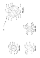
- FIGS. 3A-3D illustrate views of an exemplary self-erecting octahedron.
- FIG. 4 illustrates an exemplary methodology for constructing a self-erecting structure using shape-memory members.
- FIG. 5 illustrates an exemplary methodology for using a self-erecting structure.
- exemplary is intended to mean serving as an illustration or example of something, and is not intended to indicate a preference.
- Shape-memory materials such as, for example, shape-memory alloys (e.g., nickel-titanium) and shape-memory polymers, exhibit the ability to undergo deformation responsive to application of a force, and return to an original pre-deformation shape responsive to heating above a transition temperature that is intrinsic to the material.
- the transition temperature of a material is a property that can be determined in part by the manufacturing process of the material.
- shape-memory materials also exhibit the property of superelasticity.
- the self-erecting structures described herein are constructed by joining hub components, or fittings, that have some coupling mechanism with shape-memory members that are composed of shape-memory alloys or shape-memory polymers, wherein the spatial location of the hub components and the spatial orientation of the shape-memory members that join them defines a shape of the structure.
- the hub components of the self-erecting structure are generally positioned at vertices of a desired shape of the structure. Accordingly, hub components are hereinafter referred to as vertex hubs. It is to be understood, however, that a vertex hub, as the term is used herein, is not intended to be limited to a hub placed at a vertex of a shape.
- the shape-memory members that join the vertex hubs form edges of the desired shape.
- the orientation of the shape-memory members depends upon the position of the coupling mechanisms of the vertex hubs, and thus the position of the mechanisms on the vertex hubs partly determines the shape of the structure.
- the self-erecting cube 100 includes a plurality of vertex hubs 102 - 116 and a plurality of shape-memory members 118 - 140 .
- the spatial arrangement of the vertex hubs 102 - 116 , and the relative orientation of the shape-memory members 118 - 140 defines the shape of the self-erecting cube 100 .
- one vertex hub can be placed at each of the shape's vertices, and shape-memory members can be used to connect the vertex hubs along the shape's edges.
- each of the shape-memory members 118 - 140 connects two of the vertex hubs 102 - 116 .
- Each of the vertex hubs 102 - 116 is connected to two other vertex hubs by two respective shape-memory members.
- a top face of the cube 100 is formed by vertex hubs 102 - 108 connected by members 118 - 124 .
- Vertex hub 102 is connected to vertex hub 104 by member 120 .
- Vertex hub 104 is connected to vertex hub 106 by the member 122 .
- Vertex hub 106 is further connected to vertex hub 108 by the member 124 , and vertex hub 108 is connected to the vertex hub 102 by the member 118 , forming a square face of the cube 100 .
- the vertex hubs 102 - 108 are also connected to the vertex hubs 110 - 116 , respectively, by respective members 134 - 140 , which extend in a perpendicular direction from the square face formed by the hubs 102 - 108 and the members 118 - 124 .
- the vertex hubs 110 - 116 are further connected to one another by members 126 - 132 : hub 110 connected to hub 112 by member 128 , hub 112 in turn connected to hub 114 by member 130 , hub 114 further connected to hub 116 by member 132 , and hub 116 still further connected to hub 110 by member 126 in order to form a bottom face of the cube 100 .
- the vertex hubs 102 - 116 can be rigid plastic joints, and the coupling mechanisms of the vertex hubs 102 - 116 can be fitting openings that receive the shape-memory members 118 - 140 .
- the members 118 - 140 can be secured in the fitting openings of the vertex hubs 102 - 116 by friction fitting, wherein friction between an interior surface of a fitting opening and a surface of the member holds the member inside the fitting opening.
- the members 118 - 140 can be secured in the fitting openings with an adhesive or other coupling mechanism.
- a size and shape of the fitting openings can be dependent upon a size and shape of the shape-memory members 118 - 140 so that ends of the shape-memory members 118 - 140 fit into the fitting openings.
- the shape-memory members can be round wires having a diameter between 0.002 and 0.125 inches.
- the shape-memory members can be strips having an exemplary thickness of between 0.003 and 0.040 inches and a width of between 0.017 and 0.200 inches.
- the shape-memory strips do not deform in a direction coplanar with the thickness of the strips, and a direction of deformation of the self-erecting structure can be determined by selecting an orientation of the shape-memory members.
- the shape-memory members can be tubes having a diameter of between, for example, 0.007 inches and 0.394 inches.
- a size and shape of the shape-memory members of a self-erecting structure can depend on desirable structural characteristics of the self-erecting structure (e.g., strength, weight, etc.). It is to be understood that the vertex hubs of a self-erecting structure need not have fitting openings for receiving the shape-memory members.
- Vertex hubs of a self-erecting structure could instead use crimps, clamps, or any other coupling mechanism to hold the shape-memory members in place, provided that the vertex hubs can hold ends of shape-memory members at a fixed orientation relative to one another (e.g., 90° in the exemplary self-erecting cube 100 ).
- FIG. 1B a top view of the self-erecting cube 100 is illustrated showing vertex hubs 102 - 108 .
- FIG. 1C illustrates a bottom view of the cube 100 , and shows vertex hubs 110 - 116 .
- FIG. 1D shows a side view of the cube 100 , including vertex hubs 106 - 108 and 114 - 116 .
- the icosahedron 200 includes vertex hubs 202 - 224 and a plurality of shape-memory members (e.g., member 226 ), each of the members connecting two of the vertex hubs 202 - 224 .
- the icosahedron 200 has 20 triangular faces, each face defined by three vertex hubs and the members that connect them.
- a face of the icosahedron 200 can be open, or the face can comprise a flexible material attached to each of the members that define edges of the face.
- Each of the vertex hubs 202 - 224 of the icosahedron 200 is connected to five other vertex hubs by a shape-memory member.
- the top vertex hub 202 is connected to each of vertex hubs 204 - 212 by a respective shape-memory member.
- the vertex hubs 204 - 212 lie in a same first plane, and are positioned at five vertices of a first regular pentagon in the first plane.
- each of the vertex hubs 204 - 212 is connected to two adjacent vertex hubs in the regular pentagon.
- Vertex hub 204 is connected to hubs 206 and 212 , vertex hub 206 is further connected to hub 208 , which hub 208 is further connected to hub 210 , which hub 210 is still further connected to hub 212 .
- Five of the 20 triangular faces of the icosahedron 200 are defined by these hubs and their connecting members: a first face with vertices at hubs 202 , 204 , and 206 ; a second face with vertices at hubs 202 , 206 , and 208 ; a third face with vertices at hubs 202 , 208 , and 210 ; a fourth face with vertices at hubs 202 , 210 , and 212 ; and a fifth face with vertices at hubs 202 , 204 , and 212 .
- the vertex hubs 204 - 212 are each further connected to two of five hubs 214 - 222 that lie in a same second plane and that are positioned at five vertices of a second regular pentagon.
- the hub 204 is connected to hubs 214 and 222 ;
- the hub 206 is connected to hubs 214 and 216 ;
- the hub 208 is connected to hubs 216 and 218 ;
- the hub 210 is connected to hubs 218 and 220 ;
- hub 212 is connected to hubs 220 and 222 .
- hubs and their connecting members define an additional ten of the triangular faces of the icosahedron 200 : a sixth face with vertices at hubs 204 , 214 , and 222 ; a seventh face with vertices at hubs 204 , 206 , and 214 ; an eighth face with vertices at hubs 206 , 214 , and 216 ; a ninth face with vertices at hubs 206 , 208 , and 216 ; a tenth face with vertices at hubs 208 , 216 , and 218 ; an eleventh face with vertices at hubs 208 , 210 , and 218 ; a twelfth face with vertices at hubs 210 , 218 , and 220 ; a thirteenth face with vertices at hubs 210 , 212 , and 220 ; a fourteenth face with vertices at 212 , 220 , and
- the vertex hubs 214 - 222 are each finally connected to the bottom vertex hub 224 . These connections form the final five triangular faces of the icosahedron 200 : a sixteenth face with vertices at hubs 214 , 216 , and 224 ; a seventeenth face with vertices at hubs 216 , 218 , and 224 ; an eighteenth face with vertices at hubs 218 , 220 , and 224 ; a nineteenth face with vertices at hubs 220 , 222 , and 224 ; and a twentieth face with vertices at hubs 214 , 222 , and 224 .
- FIG. 2B a top view of the icosahedron 200 is shown.
- the top view shows top vertex hub 202 at the center, with vertex hubs 204 - 222 arranged around and below it.
- FIG. 2C presents a side view of the icosahedron 200 , at an orientation wherein only the vertex hubs 202 - 206 , 212 - 14 , and 220 - 224 are visible.
- FIG. 2D another side view of the icosahedron 200 is shown, but unlike FIG. 2C , the icosahedron 200 is depicted at an orientation at which all of the vertex hubs 202 - 224 are visible.
- the octahedron 300 comprises vertex hubs 302 - 312 and shape-memory members 314 - 336 .
- the octahedron 300 shown in FIG. 3A can also include an optional vertex hub 338 (not pictured) and shape-memory members 340 - 350 that can be included in an exemplary embodiment in which the octahedron 300 is used as a corner reflector, as described in greater detail below.
- the vertex hub 302 forms a top vertex of the octahedron 300 , and is connected to vertex hubs 304 - 310 by members 314 - 320 , respectively.
- the vertex hubs 304 - 310 lie in a same plane, and are joined together to form a square by coplanar members 322 - 328 .
- the vertex hub 304 is joined to vertex hub 306 by member 322
- hub 306 is joined to hub 308 by member 324
- hub 308 is joined to hub 310 by member 326
- hub 310 is joined to hub 304 by member 328 .
- the vertex hubs 304 - 310 are further joined to the vertex hub 312 by the members 330 - 336 , respectively.
- the octahedron 300 optionally includes a center vertex hub 338 and shape-memory members 340 - 350 .
- the center vertex hub 338 and the members 340 - 350 can be used to improve the strength of the structure 300 , or can support various materials that can be used to provide faces of the octahedron 300 , as described in greater detail below.
- the center vertex hub 338 is joined to the vertex hubs 302 - 312 by members 340 - 350 , respectively.
- FIGS. 3B-3D illustrate views of the octahedron 300 .
- FIG. 3B illustrates a top view of the octahedron 300 , wherein the vertex hub 302 serves as the top vertex of the octahedron, and the vertex hubs 304 - 310 lie in a same plane below the top hub 302 .
- FIG. 3C illustrates a bottom view of the octahedron 300 .
- the vertex hub 312 is the bottom vertex of the octahedron 300 , while the vertex hubs 304 - 310 lie in the same plane that is below the top hub 302 as shown in FIG. 3B and above the bottom hub as shown in FIG. 3C .
- FIG. 3B illustrates a top view of the octahedron 300 , wherein the vertex hub 302 serves as the top vertex of the octahedron, and the vertex hubs 304 - 310 lie in a
- 3D illustrates a side view of the octahedron 300 .
- the vertex hub 304 is nearest the viewer's position. Also in view are the top vertex hub 302 , the bottom vertex hub 312 , and vertex hubs 306 and 310 .
- various flexible materials can be attached to the shape-memory members that connect the vertex hubs such that the flexible material forms a face of a self-erecting shape or structure.
- the flexible materials that form faces of the structure also deform, and so do not interfere with the self-erecting property of the structure.
- flexible conductive weaves can be attached to the members 314 - 336 and 340 - 350 in order to form a corner reflector that can reflect electromagnetic waves back to their source.
- a first flexible weave can be attached to the members 324 and 344 - 346
- a second flexible weave can be attached to the members 316 , 340 , and 344
- a third flexible weave can be attached to the members 318 , 340 , and 346 .
- the first flexible conductive weave forms a first triangular face with the members 324 and 344 - 346 as its sides and vertex hubs 306 , 308 , and 338 as its vertices;
- the second flexible conductive weave forms a second triangular face with members 316 , 340 , and 344 as its sides and vertex hubs 302 , 306 , and 338 as its vertices;
- the third flexible conductive weave forms a third triangular face with members 318 , 340 , and 346 as its sides and vertex hubs 302 , 308 , and 338 as its vertices.
- these three faces plus an open face with members 316 - 318 and 324 as its sides, form a tetrahedron that has vertices 302 , 306 - 308 , and 338 , with the open face presented at the exterior of the octahedron 300 .
- the tetrahedron with its conductive interior triangular faces formed by the conductive weaves, can serve as a corner reflector.
- corner reflectors can be formed by similar attachment of conductive materials to various members of the octahedron, one corner reflector for each external face of the octahedron (each external face of the octahedron corresponding to an open face of one of the corner reflectors).
- the self-erecting octahedron can be used as a radar corner reflector for emergency maritime use.
- Such self-erecting octahedral corner reflector has the advantage of being able to be deformed for storage in small spaces aboard a vessel, while also being able to deploy to the necessary shape on its own in emergencies.
- the self-erecting octahedral corner reflector can be deformed to occupy a smaller volume than its deployed shape, can be constrained in some fashion to prevent its deployment, and then can be stored in a storage space prior to use.
- a user wishes to deploy the corner reflector, she can simply remove the constraint, and the corner reflector will deploy on its own by virtue of the superelasticity of its shape-memory members.
- Self-erecting structures can be constrained from deployment in many different ways, for example by placing the deformed self-erecting structure in a container, or tying it with ropes or strings.
- a transition temperature of the shape-memory members used to construct a self-erecting structure is chosen based upon a desirable operational environment for the self-erecting structure.
- the shape-memory members of a self-erecting structure can have a transition temperature that is above a standard ambient temperature of an operational environment of the structure.
- the standard ambient temperature can be, for example, room temperature (e.g., 70° F.).
- room temperature e.g., 70° F.
- the self-erecting structure can be deformed to occupy a smaller volume, allowing for easier storage.
- the self-erecting structure can subsequently be heated to a temperature above the transition temperature of the shape-memory members, whereupon the self-erecting structure will return to its original pre-deformation shape.
- the transition temperature can be selected to be below the standard ambient temperature of the operational environment, so that the structure exhibits superelasticity under standard operating conditions in the operational environment.
- the standard ambient temperature of the operational environment can vary across a range of temperatures. For example, a vessel at sea, depending on where it operates, may experience ambient temperatures between ⁇ 10° F. and 90° F.
- the transition temperature of the shape-memory members can be selected to be below such range at, for example, ⁇ 50° F.
- the shape-memory members of the self-erecting structure can have a transition temperature based upon a desirable deployment condition for the structure.
- a spacecraft, satellite, or other probe can comprise a self-erecting solar array that comprises shape-memory members and vertex hubs according to the present application.
- the shape-memory members of the self-erecting array can have a transition temperature based upon an expected steady-state temperature of the array when sunlight is incident upon it.
- the transition temperature can be, for example, 10-100° F. below the expected steady-state temperature of the array when it is in direct sunlight, thereby causing the self-erecting solar array to deploy when sunlight hits the array and begins to heat it.
- FIGS. 4-5 illustrate exemplary methodologies relating to constructing and using self-erecting structures. While the methodologies are shown and described as being a series of acts that are performed in a sequence, it is to be understood and appreciated that the methodologies are not limited by the order of the sequence. For example, some acts can occur in a different order than what is described herein. In addition, an act can occur concurrently with another act. Further, in some instances, not all acts may be required to implement a methodology described herein.
- the methodology 400 begins at 402 , and at 404 a plurality of shape-memory members are obtained, wherein the shape-memory members are made of a material that is superelastic, i.e., that returns to its original shape when an external force causing deformation is removed, above a transition temperature that is intrinsic to the material.
- a plurality of hubs is obtained at 406 , where each of the hubs has a coupling mechanism that is capable of receiving one of the shape-memory members.
- an end of one of the shape-memory members is secured in one of the coupling mechanism of one of the hubs, where the coupling mechanism can be any means of securing the end of the shape-memory member at a fixed orientation relative to an end of another shape-memory member (e.g., clamps, crimping, sockets, etc.).
- the step 408 of securing the end of the shape-memory member in the coupling mechanism of the hub is repeated until a desired shape is constructed, where the shape-memory members are edges of the shape and the hubs are the shape's vertices, whereupon the methodology 400 ends at 412 .
- FIG. 5 illustrates an exemplary methodology 500 .
- the methodology 500 begins at 502 and at 504 a structure that comprises a plurality of shape-memory members connected by a plurality of coupling devices is received, wherein the structure has an original shape.
- the structure is deformed to occupy a volume smaller than the volume of the original shape of the structure.
- the structure is constrained to occupy the volume smaller than the volume of the original shape.
- the structure can be constrained in any way that prevents the structure from returning to its original shape.
- the structure is unconstrained in its operational environment, whereupon the structure returns to its original shape without requiring external forces to reshape it, and at 512 the methodology 500 ends.
Abstract
Description
Claims (20)
Priority Applications (1)
| Application Number | Priority Date | Filing Date | Title |
|---|---|---|---|
| US15/156,132 US9695586B1 (en) | 2015-05-18 | 2016-05-16 | Self-erecting shapes |
Applications Claiming Priority (2)
| Application Number | Priority Date | Filing Date | Title |
|---|---|---|---|
| US201562163187P | 2015-05-18 | 2015-05-18 | |
| US15/156,132 US9695586B1 (en) | 2015-05-18 | 2016-05-16 | Self-erecting shapes |
Publications (1)
| Publication Number | Publication Date |
|---|---|
| US9695586B1 true US9695586B1 (en) | 2017-07-04 |
Family
ID=59191809
Family Applications (1)
| Application Number | Title | Priority Date | Filing Date |
|---|---|---|---|
| US15/156,132 Active US9695586B1 (en) | 2015-05-18 | 2016-05-16 | Self-erecting shapes |
Country Status (1)
| Country | Link |
|---|---|
| US (1) | US9695586B1 (en) |
Cited By (7)
| Publication number | Priority date | Publication date | Assignee | Title |
|---|---|---|---|---|
| US20170113817A1 (en) * | 2015-10-23 | 2017-04-27 | Raytheon Company | Spacecraft with shape memory polymer deployment mechanism |
| US20180319538A1 (en) * | 2017-05-03 | 2018-11-08 | Petar Kirilov Zaharinov | Combinations and multiplications of foldable modules and their modifications |
| US20180339822A1 (en) * | 2017-05-26 | 2018-11-29 | The Procter & Gamble Company | Flexible packages with self-folding |
| CN109375304A (en) * | 2018-12-21 | 2019-02-22 | 中国人民解放军陆军军医大学 | A kind of corner reflector |
| US10981708B2 (en) | 2017-05-26 | 2021-04-20 | The Procter & Gamble Company | Methods of self-folding flexible packages |
| US11299337B2 (en) | 2017-05-24 | 2022-04-12 | The Procter & Gamble Company | Flexible packages with flat panels |
| US11299333B2 (en) | 2017-04-04 | 2022-04-12 | The Procter & Gamble Company | Flexible packages with flat panels |
Citations (12)
| Publication number | Priority date | Publication date | Assignee | Title |
|---|---|---|---|---|
| US3277479A (en) * | 1963-09-25 | 1966-10-04 | Jr Arthur D Struble | Passive communications satellite |
| US3675667A (en) | 1970-09-25 | 1972-07-11 | Jack V Miller | Self-erecting tent |
| US4044358A (en) | 1967-09-25 | 1977-08-23 | Rockwell International Corporation | Self erectable structure |
| US5396917A (en) * | 1994-02-03 | 1995-03-14 | Hazinski; Daniel P. | Self erecting high top tent |
| US6156842A (en) | 1998-03-11 | 2000-12-05 | The Dow Chemical Company | Structures and fabricated articles having shape memory made from α-olefin/vinyl or vinylidene aromatic and/or hindered aliphatic vinyl or vinylidene interpolymers |
| US6267129B1 (en) * | 1999-08-23 | 2001-07-31 | Patent Category Corp. | Collapsible frame assemblies |
| US6374565B1 (en) * | 1999-11-09 | 2002-04-23 | Foster-Miller, Inc. | Foldable member |
| US8061660B2 (en) * | 2006-03-31 | 2011-11-22 | Composite Technology Development, Inc. | Large-scale deployable solar array |
| US8146357B2 (en) | 2005-10-28 | 2012-04-03 | The Invention Science Fund I Llc | Self assembling/quick assembly structure using shape memory alloy materials |
| US8201773B1 (en) | 2008-07-02 | 2012-06-19 | The United States Of America As Represented By Secretary Of The Navy | Flexible self-erecting substructures for sensor networks |
| US8387643B2 (en) | 2005-06-29 | 2013-03-05 | Roy Bernardus Johannes van Aalst | Self-erecting tent |
| US8813455B2 (en) * | 2011-12-07 | 2014-08-26 | Donald V. Merrifield | Deployable truss with orthogonally-hinged primary chords |
-
2016
- 2016-05-16 US US15/156,132 patent/US9695586B1/en active Active
Patent Citations (12)
| Publication number | Priority date | Publication date | Assignee | Title |
|---|---|---|---|---|
| US3277479A (en) * | 1963-09-25 | 1966-10-04 | Jr Arthur D Struble | Passive communications satellite |
| US4044358A (en) | 1967-09-25 | 1977-08-23 | Rockwell International Corporation | Self erectable structure |
| US3675667A (en) | 1970-09-25 | 1972-07-11 | Jack V Miller | Self-erecting tent |
| US5396917A (en) * | 1994-02-03 | 1995-03-14 | Hazinski; Daniel P. | Self erecting high top tent |
| US6156842A (en) | 1998-03-11 | 2000-12-05 | The Dow Chemical Company | Structures and fabricated articles having shape memory made from α-olefin/vinyl or vinylidene aromatic and/or hindered aliphatic vinyl or vinylidene interpolymers |
| US6267129B1 (en) * | 1999-08-23 | 2001-07-31 | Patent Category Corp. | Collapsible frame assemblies |
| US6374565B1 (en) * | 1999-11-09 | 2002-04-23 | Foster-Miller, Inc. | Foldable member |
| US8387643B2 (en) | 2005-06-29 | 2013-03-05 | Roy Bernardus Johannes van Aalst | Self-erecting tent |
| US8146357B2 (en) | 2005-10-28 | 2012-04-03 | The Invention Science Fund I Llc | Self assembling/quick assembly structure using shape memory alloy materials |
| US8061660B2 (en) * | 2006-03-31 | 2011-11-22 | Composite Technology Development, Inc. | Large-scale deployable solar array |
| US8201773B1 (en) | 2008-07-02 | 2012-06-19 | The United States Of America As Represented By Secretary Of The Navy | Flexible self-erecting substructures for sensor networks |
| US8813455B2 (en) * | 2011-12-07 | 2014-08-26 | Donald V. Merrifield | Deployable truss with orthogonally-hinged primary chords |
Non-Patent Citations (1)
| Title |
|---|
| "Pop Up Ball", Whitney Woods, Retrieved at: <<http://www.whitneywoods.co.uk/products/pop-up-ball/>>, Retrieved Date: Apr. 18, 2016, pp. 1-11. |
Cited By (13)
| Publication number | Priority date | Publication date | Assignee | Title |
|---|---|---|---|---|
| US20170113817A1 (en) * | 2015-10-23 | 2017-04-27 | Raytheon Company | Spacecraft with shape memory polymer deployment mechanism |
| US10518908B2 (en) * | 2015-10-23 | 2019-12-31 | Raytheon Company | Spacecraft with shape memory polymer deployment mechanism |
| US11299333B2 (en) | 2017-04-04 | 2022-04-12 | The Procter & Gamble Company | Flexible packages with flat panels |
| US20180319538A1 (en) * | 2017-05-03 | 2018-11-08 | Petar Kirilov Zaharinov | Combinations and multiplications of foldable modules and their modifications |
| US11814214B2 (en) * | 2017-05-03 | 2023-11-14 | Difold Inc. | Collapsible article comprising combinations and multiplications of foldable sections |
| US11299337B2 (en) | 2017-05-24 | 2022-04-12 | The Procter & Gamble Company | Flexible packages with flat panels |
| US10926930B2 (en) * | 2017-05-26 | 2021-02-23 | The Procter & Gamble Company | Flexible packages with self-folding |
| US10981708B2 (en) | 2017-05-26 | 2021-04-20 | The Procter & Gamble Company | Methods of self-folding flexible packages |
| US10549896B2 (en) * | 2017-05-26 | 2020-02-04 | The Procter & Gamble Plaza | Flexible packages with self-folding |
| US11312550B2 (en) | 2017-05-26 | 2022-04-26 | The Procter & Gamble Company | Flexible packages with self-folding |
| US20180339822A1 (en) * | 2017-05-26 | 2018-11-29 | The Procter & Gamble Company | Flexible packages with self-folding |
| CN109375304A (en) * | 2018-12-21 | 2019-02-22 | 中国人民解放军陆军军医大学 | A kind of corner reflector |
| CN109375304B (en) * | 2018-12-21 | 2024-01-23 | 中国人民解放军陆军军医大学 | Corner reflector |
Similar Documents
| Publication | Publication Date | Title |
|---|---|---|
| US9695586B1 (en) | Self-erecting shapes | |
| Liu et al. | Shape memory polymers and their composites in aerospace applications: a review | |
| Rossiter et al. | Shape memory polymer hexachiral auxetic structures with tunable stiffness | |
| Jacobs et al. | Deployable auxetic shape memory alloy cellular antenna demonstrator: design, manufacturing and modal testing | |
| US6772479B2 (en) | Conductive shape memory metal deployment latch hinge | |
| US9281569B2 (en) | Deployable reflector | |
| US20020195177A1 (en) | Conductive shape memory metal deployment latch hinge deployment method | |
| US8259033B2 (en) | Furlable shape-memory spacecraft reflector with offset feed and a method for packaging and managing the deployment of same | |
| Koh et al. | Self-folding origami using torsion shape memory alloy wire actuators | |
| CN105356029A (en) | Planar reflection array antenna based on shape memory polymer composite material hinge and expansion method thereof | |
| US20170030519A1 (en) | Container having an internal structure with minimum surfaces | |
| US11505938B2 (en) | Flexible space frame components and method of construction | |
| Bastaits et al. | Multi-layer adaptive thin shells for future space telescopes | |
| Ochoa et al. | Deployable helical antenna for nano-satellites | |
| GB2555656A (en) | Deployable wrapped rib assembly | |
| An et al. | Quantitative evaluation of the three-dimensional deployment behavior of a shape memory polymer antenna | |
| US9680229B2 (en) | Modular reflector assembly for a reflector antenna | |
| JP6448293B2 (en) | Structural member deployment system | |
| Zeng et al. | A Shape-Memory Deployable Subsystem with a Large Folding Ratio in China’s Tianwen-1 Mars Exploration Mission | |
| Wang et al. | Six-ray folded configurations as the geometric basis of thin-walled elements in engineering structures | |
| Reading | Self-erecting shapes | |
| Liu et al. | Applications of shape-memory polymers in aerospace | |
| Beavers et al. | Design and testing of an elastic memory composite deployment hinge for spacecraft | |
| Sinn et al. | Inflatable structures for Mars base 10 | |
| Sinn et al. | Bio-inspired programmable matter for space applications |
Legal Events
| Date | Code | Title | Description |
|---|---|---|---|
| AS | Assignment |
Owner name: SANDIA CORPORATION, NEW MEXICO Free format text: ASSIGNMENT OF ASSIGNORS INTEREST;ASSIGNOR:READING, MATTHEW W.;REEL/FRAME:038916/0752 Effective date: 20160608 |
|
| AS | Assignment |
Owner name: U.S. DEPARTMENT OF ENERGY, DISTRICT OF COLUMBIA Free format text: CONFIRMATORY LICENSE;ASSIGNOR:SANDIA CORPORATION;REEL/FRAME:038965/0980 Effective date: 20160606 |
|
| STCF | Information on status: patent grant |
Free format text: PATENTED CASE |
|
| AS | Assignment |
Owner name: NATIONAL TECHNOLOGY & ENGINEERING SOLUTIONS OF SAN Free format text: CHANGE OF NAME;ASSIGNOR:SANDIA CORPORATION;REEL/FRAME:045852/0814 Effective date: 20170501 |
|
| MAFP | Maintenance fee payment |
Free format text: PAYMENT OF MAINTENANCE FEE, 4TH YEAR, LARGE ENTITY (ORIGINAL EVENT CODE: M1551); ENTITY STATUS OF PATENT OWNER: LARGE ENTITY Year of fee payment: 4 |