US9509587B1 - Hardware root of trust (HROT) for internet protocol (IP) communications - Google Patents
Hardware root of trust (HROT) for internet protocol (IP) communications Download PDFInfo
- Publication number
- US9509587B1 US9509587B1 US14/662,870 US201514662870A US9509587B1 US 9509587 B1 US9509587 B1 US 9509587B1 US 201514662870 A US201514662870 A US 201514662870A US 9509587 B1 US9509587 B1 US 9509587B1
- Authority
- US
- United States
- Prior art keywords
- ethernet
- packets
- hrot
- network
- network probe
- Prior art date
- Legal status (The legal status is an assumption and is not a legal conclusion. Google has not performed a legal analysis and makes no representation as to the accuracy of the status listed.)
- Active, expires
Links
Images


Classifications
-
- H—ELECTRICITY
- H04—ELECTRIC COMMUNICATION TECHNIQUE
- H04L—TRANSMISSION OF DIGITAL INFORMATION, e.g. TELEGRAPHIC COMMUNICATION
- H04L45/00—Routing or path finding of packets in data switching networks
- H04L45/02—Topology update or discovery
-
- H—ELECTRICITY
- H04—ELECTRIC COMMUNICATION TECHNIQUE
- H04L—TRANSMISSION OF DIGITAL INFORMATION, e.g. TELEGRAPHIC COMMUNICATION
- H04L63/00—Network architectures or network communication protocols for network security
- H04L63/08—Network architectures or network communication protocols for network security for authentication of entities
- H04L63/0876—Network architectures or network communication protocols for network security for authentication of entities based on the identity of the terminal or configuration, e.g. MAC address, hardware or software configuration or device fingerprint
-
- H04L29/0653—
-
- H—ELECTRICITY
- H04—ELECTRIC COMMUNICATION TECHNIQUE
- H04L—TRANSMISSION OF DIGITAL INFORMATION, e.g. TELEGRAPHIC COMMUNICATION
- H04L43/00—Arrangements for monitoring or testing data switching networks
- H04L43/10—Active monitoring, e.g. heartbeat, ping or trace-route
- H04L43/106—Active monitoring, e.g. heartbeat, ping or trace-route using time related information in packets, e.g. by adding timestamps
-
- H—ELECTRICITY
- H04—ELECTRIC COMMUNICATION TECHNIQUE
- H04L—TRANSMISSION OF DIGITAL INFORMATION, e.g. TELEGRAPHIC COMMUNICATION
- H04L45/00—Routing or path finding of packets in data switching networks
- H04L45/02—Topology update or discovery
- H04L45/036—Updating the topology between route computation elements, e.g. between OpenFlow controllers
-
- H—ELECTRICITY
- H04—ELECTRIC COMMUNICATION TECHNIQUE
- H04L—TRANSMISSION OF DIGITAL INFORMATION, e.g. TELEGRAPHIC COMMUNICATION
- H04L45/00—Routing or path finding of packets in data switching networks
- H04L45/26—Route discovery packet
-
- H—ELECTRICITY
- H04—ELECTRIC COMMUNICATION TECHNIQUE
- H04L—TRANSMISSION OF DIGITAL INFORMATION, e.g. TELEGRAPHIC COMMUNICATION
- H04L45/00—Routing or path finding of packets in data switching networks
- H04L45/38—Flow based routing
-
- H—ELECTRICITY
- H04—ELECTRIC COMMUNICATION TECHNIQUE
- H04L—TRANSMISSION OF DIGITAL INFORMATION, e.g. TELEGRAPHIC COMMUNICATION
- H04L45/00—Routing or path finding of packets in data switching networks
- H04L45/58—Association of routers
- H04L45/586—Association of routers of virtual routers
-
- H—ELECTRICITY
- H04—ELECTRIC COMMUNICATION TECHNIQUE
- H04L—TRANSMISSION OF DIGITAL INFORMATION, e.g. TELEGRAPHIC COMMUNICATION
- H04L45/00—Routing or path finding of packets in data switching networks
- H04L45/64—Routing or path finding of packets in data switching networks using an overlay routing layer
-
- H—ELECTRICITY
- H04—ELECTRIC COMMUNICATION TECHNIQUE
- H04L—TRANSMISSION OF DIGITAL INFORMATION, e.g. TELEGRAPHIC COMMUNICATION
- H04L45/00—Routing or path finding of packets in data switching networks
- H04L45/66—Layer 2 routing, e.g. in Ethernet based MAN's
-
- H—ELECTRICITY
- H04—ELECTRIC COMMUNICATION TECHNIQUE
- H04L—TRANSMISSION OF DIGITAL INFORMATION, e.g. TELEGRAPHIC COMMUNICATION
- H04L45/00—Routing or path finding of packets in data switching networks
- H04L45/74—Address processing for routing
-
- H—ELECTRICITY
- H04—ELECTRIC COMMUNICATION TECHNIQUE
- H04L—TRANSMISSION OF DIGITAL INFORMATION, e.g. TELEGRAPHIC COMMUNICATION
- H04L47/00—Traffic control in data switching networks
- H04L47/10—Flow control; Congestion control
-
- H—ELECTRICITY
- H04—ELECTRIC COMMUNICATION TECHNIQUE
- H04L—TRANSMISSION OF DIGITAL INFORMATION, e.g. TELEGRAPHIC COMMUNICATION
- H04L49/00—Packet switching elements
- H04L49/70—Virtual switches
-
- H04L61/2007—
-
- H—ELECTRICITY
- H04—ELECTRIC COMMUNICATION TECHNIQUE
- H04L—TRANSMISSION OF DIGITAL INFORMATION, e.g. TELEGRAPHIC COMMUNICATION
- H04L63/00—Network architectures or network communication protocols for network security
- H04L63/12—Applying verification of the received information
- H04L63/126—Applying verification of the received information the source of the received data
-
- H—ELECTRICITY
- H04—ELECTRIC COMMUNICATION TECHNIQUE
- H04L—TRANSMISSION OF DIGITAL INFORMATION, e.g. TELEGRAPHIC COMMUNICATION
- H04L69/00—Network arrangements, protocols or services independent of the application payload and not provided for in the other groups of this subclass
- H04L69/22—Parsing or analysis of headers
Definitions
- IP communication systems transfer IP packets among user devices and intelligent machines to provide data communication services like internet access, file transfers, media streaming, and user messaging.
- the IP communication systems are implementing several technologies in a contemporaneous manner to improve service delivery. These technologies include systems for Hardware Root-of-Trust (HRoT), Network Function Virtualization (NFV), and Software-Defined Networks (SDNs).
- HRoT Hardware Root-of-Trust
- NFV Network Function Virtualization
- SDNs Software-Defined Networks
- the HRoT systems ensure network security and control.
- the HRoT systems maintain physical separation between trusted hardware and untrusted hardware.
- the HRoT systems control software access to the trusted hardware but allow interaction between open and trusted software components through secure bus interfaces, memories, and switching circuits.
- the HRoT systems establish HRoT with one another by using secret HRoT keys physically embedded in their hardware to generate hash results for remote verification by other HRoT systems that know the secret HRoT keys and hash algorithms.
- NFV computer platforms run hypervisor software to execute various software modules during sets of processing time cycles—referred to as NFV time slices.
- the software modules often comprise virtual machines, such as virtual IP routers, Layer 2 switches, and the like.
- virtual machines such as virtual IP routers, Layer 2 switches, and the like.
- Different networks are mapped to different NFV time slices to isolate the networks from one another.
- SDNs have separate control and data planes.
- SDN controllers interact with SDN applications to control SDN data plane machines.
- the SDN applications process application-layer data to direct the SDN controllers, and in response, the SDN controllers direct the SDN data plane machines to process and transfer IP packets.
- the SDN applications may comprise gateways, servers, and the like.
- a communication system determines Hardware Root-of-Trust (HRoT) trust for Internet Protocol (IP) communications.
- a probe transfers probe packets having an originating IP address, destination IP address, and IP HRoT reporting parameter.
- IP routers receive the probe packets through input interfaces and route the probe packets from the input interfaces to output interfaces. Responsive to the IP HRoT reporting parameter, the IP routers encode router Hardware Identifiers (HW IDs) for transfer in probe responses to the probe system.
- the probe responses indicate the encoded router HW IDs, IP input interfaces, and IP output interfaces.
- the probe system processes the probe responses to identify an end-to-end IP communication path for the originating IP address and destination IP address based on the IP interfaces.
- the network probe system determines hardware trust status for the end-to-end IP communication path based on the encoded IP router HW IDs.
- FIGS. 1-3 illustrate a data communication system to verify Hardware Root-of-Trust (HRoT) for Internet Protocol (IP) communication paths that traverse IP routers.
- HRoT Hardware Root-of-Trust
- IP Internet Protocol
- FIGS. 4-5 illustrate a data communication system to integrate HRoT for IP communication paths that traverse IP routers and Ethernet switches.
- FIGS. 6-7 illustrates a data communication system to integrate HRoT for IP communication paths that traverse Network Function Virtualization (NFV) servers and Software-Defined Network (SDN) IP flow controllers.
- NFV Network Function Virtualization
- SDN Software-Defined Network
- FIGS. 8-9 illustrate network computer systems to integrate IP, HRoT, and NFV systems.
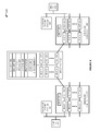
- FIGS. 1-3 illustrate data communication system 100 to verify Hardware Root-of-Trust (HRoT) for Internet Protocol (IP) communication paths.
- data communication system 100 also verifies proper Network Function Virtualization (NFV) time slices for the IP communication paths.
- Data communication system 100 comprises IP routers 101 - 104 and network probe systems 161 - 162 .
- IP routers 101 - 104 include respective IP input interfaces 111 - 122 and IP output interfaces 131 - 142 .
- IP routers 101 - 104 also include respective Hardware Identifiers (HW IDs) 151 - 154 .
- HW IDs Hardware Identifiers
- IP interfaces 111 - 122 and 131 - 142 comprise physical Layer 2 connections such as Ethernet, Software-Defined Network (SDN), Long Term Evolution (LTE), Data Over Cable Service Interface Specification (DOCSIS), Time Division Multiplex (TDM), Synchronous Optical Network (SONET), or some other data link interface.
- the physical Layer 2 connection comprises virtual IP links over physical NFV server circuitry.
- Input interfaces 111 - 112 in IP router 101 are coupled to network probe system 161 and IP end-point 171 over Layer 2 communication systems.
- Output interfaces 140 - 141 in IP router 104 are coupled to network probe system 162 and IP end-point 172 over Layer 2 communication systems.
- IP end-points 171 - 172 comprise computers, servers phones, or some other type of intelligent machine.
- Network probe systems 161 - 162 comprise computer systems that are also IP-end-points.
- IP routers 101 - 104 comprise computer systems that are coupled to one another over Layer 2 communication systems.
- One or more of IP routers 101 - 104 , network probe systems 161 - 162 , and IP end-points 171 - 172 may be virtual machines executing on NFV computer systems.
- output interface 131 in IP router 101 is coupled to input interface 116 in IP router 102 .
- Output interface 132 in IP router 101 is coupled to input interface 121 in IP router 104 .
- Output interface 133 in IP router 101 is coupled to input interface 117 in IP router 103 .
- Output interface 136 in IP router 102 is coupled to input interface 120 in IP router 104 .
- Output interface 137 in IP router 103 is coupled to input interface 122 in IP router 104 .
- IP routers 101 - 104 share and maintain routing information.
- IP routers 101 - 104 receive IP packets having IP addresses into input interfaces 111 - 122 .
- IP routers 101 - 104 transfer the IP packets from input interfaces 111 - 122 to output interfaces 131 - 142 over internal communication circuitry based on the IP packet addresses and the routing information.
- end-point systems 171 may obtain IP addresses and use these IP addresses to exchange IP packets over an end-to-end IP communication path formed by IP routers 101 - 104 .
- IP routers 101 - 104 execute HRoT software to establish and maintain hardware trust for their circuitry, memory, and communication interfaces. For example, IP router 101 reads its physically-embedded HW ID 151 and generates a trust value using a one-way hash on HW ID 151 and a random number. IP router 101 transfers the trust value to network probe system 161 . Network probe system 161 then remotely verifies HRoT for IP router 101 by generating its own trust value with HW ID 151 and the random number.
- Probe systems 161 - 162 may comprise a Dynamic Host Configuration Protocol (DHCP) system that probes for HRoT using the same IP address prefixes as endpoints 171 - 172 .
- DHCP Dynamic Host Configuration Protocol
- network probe system 161 transfers network IP probe packets that have an originating IP address, a destination IP address, and an IP HRoT reporting parameter.
- the IP HRoT reporting parameter comprises a particular IP destination port number and/or IP source port number.
- the IP HRoT reporting parameter comprises a special IP HRoT.
- the HRoT reporting parameter may also comprise a flag or value placed in the IP header portion of the probe packets.
- IP router 101 receives the network probe packets through IP input interfaces 111 - 112 and routes the probe packets from IP input interfaces 111 - 112 to IP output interfaces 131 - 133 based on the IP addresses and its routing information. Note that the probe packets having the same address pairs take different physical routes based on variables in the routing information. For example, output interface 132 may become heavily loaded, so router 101 begins to use output interfaces 131 and 133 to handle the traffic burst.
- IP router 101 Responsive to the IP HRoT reporting parameter, IP router 101 encodes its HW ID 151 and transfers a probe response packet to network probe system 161 that indicate encoded HW ID 151 for IP router 101 .
- the probe response packet also indicates the IP addresses, IP input interfaces 111 - 112 , and IP output interfaces 131 - 133 that were used to transfer the network probe packets having the HRoT reporting parameter.
- IP routers 102 - 104 receive the network probe packets through IP input interfaces 116 - 117 and 120 - 122 and route the probe packets to IP output interfaces 136 - 137 and 140 - 141 based on the IP addresses and routing information. Responsive to the IP HRoT reporting parameter, IP routers 102 - 104 encode their HW IDs 152 - 154 and transfer probe response packets to network probe system 161 that indicate encoded HW IDs 152 - 154 for IP routers 102 - 104 .
- the probe response packets also indicate the IP addresses, IP input interfaces 116 - 117 and 120 - 122 , and IP output interfaces 136 - 137 and 140 - 141 that were used to transfer the network probe packets.
- Network probe system 162 also receives the network probe packets from IP output interfaces 140 - 141 , and responsive to the IP HRoT reporting parameter, returns a probe response packet to network probe system 161 indicating that the IP end-point has been reached.
- Network probe system 161 processes the probe response packets to identify an end-to-end IP communication path for the originating IP address and the destination IP address based on IP input interfaces 111 - 112 , 116 - 117 , and 120 - 122 and IP output interfaces 131 - 133 , 136 - 137 , and 140 - 141 .
- Network probe system 161 determines hardware trust status for the end-to-end IP communication path formed by interfaces 111 - 112 , 116 - 117 , 120 - 122 , 131 - 133 , 136 - 137 , and 140 - 141 based on the encoded IP router HW IDs 151 - 154 for the associated IP routers 101 - 104 .
- Network probe system 161 uses network topology data to associate the specific input and output interfaces with their routers and their external Layer 2 connections. For example, the network topology data would associate output interface 131 with IP router 101 and with input interface 116 based on the Layer 2 data link. The topology data would associate input interface 116 with router 102 . The network topology data may also be used to verify hardware trust. For example, network probe system 161 can verify that all reported IP output interfaces are coupled to one of the reported IP input interfaces or to an IP endpoint. If network probe system 161 detects that one of the reported IP output interfaces is not properly coupled (like if output interface 139 was reported), then network probe system 161 could determine that the IP communications path using the IP addresses is untrusted at the hardware level.
- Layer 2 devices like Ethernet switches and SDN IP flow controllers also report their HW IDs and input/output interfaces for the probe packets responsive to the HRoT reporting parameter.
- Network probe system 161 determines HRoT for the IP communication path at Layer 2 in addition to Layer 3.
- network probe system 161 transfers an NFV reporting parameter in the network IP probe packets along with the HRoT reporting parameter.
- the NFV reporting parameter may also comprise or share a particular IP destination port number and/or IP source port number.
- IP routers 101 - 104 receive the network probe packets, and responsive to the NFV reporting parameter, IP routers 101 - 104 identify their NFV time slices used to transfer the network probe packets. IP routers 101 - 104 transfer their NFV time-slice data for the IP address pair in the probe response packets to network probe system 161 .
- Network probe system 161 processes the probe response packets to verify the proper NFV time slices for the end-to-end IP communication path for the originating IP address and the destination IP address. Typically, network probe system 161 uses network topology data to associate the routers and their target NFV time slices. If network probe system 161 identifies a reported NFV time slice that is not a proper target slice, then network probe system 161 determines that the IP communications path using the IP addresses is untrusted at the NFV level.
- Network probe system 161 transfers network IP probe packets that have an originating IP address, a destination IP address, and an IP HRoT reporting parameter ( 201 ).
- IP routers 101 - 104 receive the network probe packets through their IP input interfaces and route the probe packets to their IP output interfaces based on at least the destination IP address ( 202 ). Responsive to the IP HRoT reporting parameter, IP routers 101 - 104 encode their Hardware IDs (HW IDs) and transfer probe response packets to network probe system 161 that indicate the encoded HW IDs for IP routers 101 - 104 .
- HW IDs Hardware IDs
- the probe response packets also indicate the IP input interfaces and the IP output interfaces that were used to transfer the network probe packets having the HRoT reporting parameter ( 203 ).
- network probe system 162 receives the network probe packets and returns probe response packets to network probe system 161 indicating that the IP end-point has been reached.
- Network probe system 161 processes the probe response packets to identify an end-to-end IP communication path for the originating IP address and the destination IP address based on the IP input interfaces and the IP output interfaces ( 204 ).
- Network probe system 161 determines hardware trust status for the end-to-end IP communication path formed by the input and output interfaces based on the encoded HW IDs for IP routers 101 - 104 ( 205 ).
- Network probe system 161 performs an HRoT/NFV process on IP address pairs. For example, network probe system 161 may verify HRoT and NFV trust for all IP address pairs in an IP address block before individual address are allocated from the block (and current IP addresses are de-allocated for HRoT and NFV verification).
- network probe system 161 transfers network IP probe packets that have an originating IP address and port number and a destination IP address and port number, where the port number combination represents an HRoT and NFV reporting parameter to IP routers 101 - 104 .
- IP router 101 receives the network probe packets routes the probe packets to routers 102 - 104 based on the IP addresses and routing information. Responsive to the IP HRoT/NFV reporting parameters, IP router 101 encodes its HW ID and transfers probe response packets to network probe system 161 that indicate encoded HW ID for IP router 101 .
- the probe response packets also indicate the IP addresses, communication interfaces, and NFV Time Slices (TS) used by router 101 to transfer the network probe packets.
- TS NFV Time Slices
- IP router 102 receives some of the network probe packets and routes the probe packets to router 104 based on the IP addresses and routing information. Responsive to the IP HRoT/NFV reporting parameters, IP router 102 encodes its HW ID and transfers probe response packets to network probe system 161 that indicate encoded HW ID for IP router 102 . The probe response packets also indicate the IP addresses, communication interfaces, and NFV Time Slices (TS) used by router 102 to transfer the network probe packets.
- TS NFV Time Slices
- IP router 103 receives some of the network probe packets and routes the probe packets to router 104 based on the IP addresses and routing information. Responsive to the IP HRoT/NFV reporting parameters, IP router 103 encodes its HW ID and transfers probe response packets to network probe system 161 that indicate encoded HW ID for IP router 102 . The probe response packets also indicate the IP addresses, communication interfaces, and NFV Time Slices (TS) used by router 103 to transfer the network probe packets.
- TS NFV Time Slices
- IP router 104 receives the network probe packets and routes the probe packets to network probe system 162 based on the IP addresses and routing information. Responsive to the IP HRoT/NFV reporting parameters, IP router 104 encodes its HW ID and transfers probe response packets to network probe system 161 that indicate encoded HW ID for IP router 104 . The probe response packets also indicate the IP addresses, communication interfaces, and NFV Time Slices (TS) used by router 104 to transfer the network probe packets.
- TS NFV Time Slices
- Network probe system 162 also receives the network probe packets from router 104 and returns probe response packets network probe system 161 indicating that the IP end-point has been reached.
- Network probe system 161 processes the probe response packets to identify an end-to-end IP communication path for the originating IP address and the destination IP address based on the reported IP input and output interfaces.
- Network probe system 161 determines the hardware trust status for the end-to-end IP communication path based on the HW IDs for IP routers 101 - 104 and the IP end-point reached messages.
- Network probe system 161 uses network topology data to associate the specific input and output interfaces with their routers and their inter-router connections.
- the network topology data is used to verify hardware trust.
- network probe system 161 can use the topology data to verify that all reported IP output interfaces are linked to a reported input interface or endpoint. If network probe system 161 detects that a reported IP output interface does not have a proper termination, then network probe system 161 determines that the IP communications path using the IP addresses is untrusted at the hardware level.
- Network probe system also compares the NFV time slice data for routers 101 - 104 to target NFV time slices in the network topology data. If network probe system 161 detects that an improper time slice has been used, then network probe system 161 determines that the IP communications path using the IP addresses is untrusted at the NFV level.
- FIGS. 4-5 illustrate data communication system 400 to integrate HRoT for IP communication paths that traverse IP routers 401 - 402 and Ethernet switches 403 - 404 .
- Data communication system 400 comprises IP routers 401 - 402 , Ethernet switches 403 - 404 , and network probe systems 461 - 462 .
- IP routers 401 - 402 include respective IP input interfaces 411 - 416 and IP output interfaces 431 - 436 .
- IP routers 101 - 102 also include respective HW IDs 451 - 452 .
- IP routers 401 - 402 may be virtual machines or containers executing in an NFV environment.
- Ethernet switches 403 - 404 include respective Ethernet input interfaces 417 - 422 and Ethernet output interfaces 437 - 442 .
- Ethernet switches 403 - 404 also include respective HW IDs 453 - 454 .
- Ethernet interfaces 417 - 422 and 437 - 442 comprise physical Ethernet ports having Layer 1 connections like metal or glass.
- Network probe system 461 is coupled to input IP interface 413 in IP router 401 .
- Output IP interface 433 in IP router 401 is coupled to input Ethernet interface 417 in Ethernet switch 403 .
- Output Ethernet interface 437 in Ethernet switch 403 is coupled to input Ethernet interface 420 in Ethernet switch 404 .
- Output interface 440 in Ethernet switch 404 is coupled to input interface 416 in IP router 402 .
- Output interface 436 in IP router 102 is coupled to network probe system 462 .
- Network probe systems 461 - 462 establish HRoT with one another.
- Network probe systems 461 - 462 identify IP address pairs for HRoT verification.
- network probe systems 461 - 462 may provide Dynamic Host Configuration Protocol (DHCP) services and rotate blocks of IP addresses through the HRoT verification process.
- DHCP Dynamic Host Configuration Protocol
- Network probe system 461 transfers varying loads of IP network probe packets with one of the IP address pairs and with IP and Ethernet HRoT reporting parameters to IP router 401 .
- probe system 161 transmits the IP network probe packets in Ethernet frames having an Ethernet HRoT reporting parameter.
- IP router 401 receives network probe packets with the HRoT reporting parameters into input interface 413 .
- IP router 401 routes some of these IP packets to IP router 402 through Ethernet switches 403 - 404 .
- IP router 401 encodes its HW ID 451 and transfers probe response packets to network probe system 461 .
- IP router 401 places an Ethernet HRoT reporting parameter in the Ethernet frames transporting the IP network probe packets to Ethernet switch 403 .
- the HRoT reporting parameter at the IP layer may comprise IP port combinations, while the HRoT reporting parameter at the Ethernet layer comprises a special Ethertype data.
- IP address prefix pools are associated with Ethernet MAC prefix pools, and a combination of these IP and Ethernet prefixes represent the HRoT reporting parameter at both the IP and Ethernet layers.
- Ethernet switch 403 receives the Ethernet frames into input Ethernet interface 417 that have Ethernet HRoT reporting parameters and that encapsulate IP network probe packets with the IP HRoT reporting parameters. Ethernet switch 403 switches these Ethernet frames with IP probe packets to Ethernet output interface 437 based on Ethernet addressing for the Layer 2 connection between IP routers 401 - 402 . Responsive to the IP and/or Ethernet HRoT reporting parameters, Ethernet switch 403 encodes its HW ID 453 and transfers IP probe response packets to network probe system 461 . The probe response packets also indicate Ethernet interfaces 417 and 437 that were used for the probe packet transfer.
- Ethernet switch 404 receives the Ethernet frames with the IP probe packets each having the HRoT reporting parameters into input Ethernet interface 420 .
- Ethernet switch 404 switches these Ethernet frames with the IP probe packets to Ethernet output interface 440 based on Ethernet addressing for the Layer 2 connection between IP routers 401 - 402 .
- Ethernet switch 404 encodes its HW ID 454 and transfers IP probe response packets to network probe system 461 .
- the probe response packets also indicate Ethernet interfaces 420 and 440 that were used for the IP probe packet transfer.
- IP router 402 receives the IP network probe packets with the HRoT reporting parameters into input interface 416 . IP router 402 routes these probe packets to network probe system 462 . Responsive to the IP HRoT reporting parameters, IP router 402 encodes its HW ID 452 and transfers IP probe response packets to network probe system 461 . Network probe system 462 also reports the IP communication path end-point to network probe system 461 responsive to the IP network probe packets.
- Network probe system 461 processes the probe response packets to identify an end-to-end IP communication path for the originating IP address and the destination IP address based on the string of IP and Ethernet interfaces ( 413 , 433 , 417 , 437 , 420 , 440 , 416 , and 436 ) and the reports from IP end-point probe system 462 .
- Network probe system 461 determines hardware trust status for the end-to-end IP communication path formed by these interfaces based on the encoded HW IDs 451 - 454 for the associated IP routers 401 - 402 and Ethernet switches 403 - 404 .
- Network probe system 461 verifies that all reported IP and Ethernet interfaces are coupled per the network topology and use hardware with HRoT.
- network probe system 461 transfers varying loads of IP network probe packets to IP router 401 with an IP address pair and IP/Ethernet (ENET) HRoT reporting parameters.
- IP router 401 routes some of these IP packets to IP router 402 through Ethernet switches 403 - 404 .
- IP router 401 encodes and transfers its HW ID in probe response packets to network probe system 461 that also indicate the IP interfaces used.
- IP router 401 places an Ethernet (ENET) HRoT reporting parameter in the Ethernet frames transporting the IP network probe packets to Ethernet switch 403 .
- ENET Ethernet
- Ethernet switch 403 receives the Ethernet frames that contain Ethernet HRoT reporting parameters and the IP network probe packets with the IP HRoT reporting parameters. Ethernet switch 403 switches these Ethernet frames with the IP probe packets to Ethernet switch 404 based on Ethernet addressing for the Layer 2 connection between IP routers 401 - 402 . Responsive to the Ethernet HRoT reporting parameters, Ethernet switch 403 encodes its HW ID and transfers IP probe response packets to network probe system 461 that indicate the HW ID and the Ethernet interfaces used.
- Ethernet switch 404 receives the Ethernet frames that contain Ethernet HRoT reporting parameters and the IP network probe packets with the IP HRoT reporting parameters. Ethernet switch 404 switches these Ethernet frames with the IP probe packets to IP router 402 based on Ethernet addressing for the Layer 2 connection between IP routers 401 - 402 . Responsive to the Ethernet HRoT reporting parameters, Ethernet switch 404 encodes its HW ID and transfers IP probe response packets to network probe system 461 that indicate the HW ID and the Ethernet interfaces used.
- IP router 402 receives the IP network probe packets with the HRoT reporting parameters. IP router 402 routes these probe packets to network probe system 462 . Responsive to the IP HRoT reporting parameters, IP router 402 encodes its HW ID and transfers IP probe response packets to network probe system 461 indicating the encoded HW ID and the IP interfaces used.
- Network probe system 462 receives the IP network probe packets with the HRoT reporting parameters. Responsive to the IP network probe packets, network probe system 462 reports to network probe system 461 that the end-point for the IP communication path has been reached.
- Network probe system 461 processes the probe response packets to identify an end-to-end IP communication path for the originating IP address and the destination IP address based on the reports from routers 401 - 402 , Ethernet switches 403 - 404 , and probe system 462 .
- Network probe system 461 determines hardware trust status for the end-to-end IP communication path formed by these interfaces based on the encoded HW IDs for the associated IP routers 401 - 402 and Ethernet switches 403 - 404 .
- Network probe system 461 verifies that all reported IP and Ethernet interfaces are coupled per the network topology and use hardware with HRoT.
- FIGS. 6-7 illustrate data communication system 600 to integrate HRoT for IP communication paths that traverse NFV server 601 and SDN flow controllers 602 - 603 .
- Data communication system 600 comprises NFV server 601 , SDN flow controllers 602 - 603 , and network probe systems 661 - 662 .
- Data communication system 600 is configured to operate according to SDN and NFV standards.
- SDN flow controllers 602 - 603 include respective SDN/IP input interfaces 611 - 616 and SDN/IP output interfaces 631 - 636 .
- SDN flow controllers 602 - 603 include respective HW IDs 652 - 653 .
- SDN flow controllers 602 - 603 comprise physical IP routing machines that direct individual flows of IP packets from incoming interfaces to outgoing interfaces based on IP flow tables.
- SDN flow controllers 602 - 603 may also apply packet-level features such as header translation, media transcoding, payload inspection, caching, and the like based on the flow tables.
- the SDN controller VMs in NFV server 601 use southbound SDN interfaces to load the flow tables in SDN flow controllers 602 - 603 .
- NFV server 601 includes respective SDN/IP input interfaces 617 - 619 and SDN/IP output interfaces 637 - 639 .
- Output SDN/IP interface 631 in SDN flow controller 602 is coupled to input SDN/IP interface 619 in NFV server 601 .
- Output SDN/IP interface 639 in NFV server 601 is coupled to input SDN/IP interface 614 in SDN flow controller 603 .
- SDN/IP interfaces 611 - 619 and 631 - 639 comprise physical SDN communication ports.
- NFV server 601 comprises Central Processing Units (CPUs), memory devices, and communication circuitry to couple SDN/IP input interfaces 617 - 619 with SDN/IP output interfaces 637 - 639 .
- the communication circuitry and interfaces in NFV server 601 may be similar to an SDN IP flow controller.
- the hardware in NFV server 601 (CPUs, memory devices, communication circuitry, and the like) has a physically-embedded HW ID 651 .
- NFV server 601 includes an HRoT system.
- the HRoT system includes portions of the circuitry, memory, and interfaces in NFV server 601 .
- the HRoT system establishes and maintains physical control over software and data access to the hardware in NFV server 601 .
- the HRoT system establishes the direct physical control by loading trust software during NFV server 601 initialization.
- the HRoT system includes physical switching to couple and de-couple select components in NFV server 601 , such as select CPUs, memory devices, interfaces, and the like.
- the HRoT system may use the switching to read HW ID 651 that is embedded within NFV server 601 .
- the HRoT system exchanges trust data with other HRoT systems using a hash of HW ID 651 to validate itself.
- the HRoT system hosts trust data to validate HRoT systems in SDN flow controllers 602 - 603 .
- NFV server 601 has an NFV system comprising hypervisor software and context switching support in the CPUs and memory.
- the hypervisor software directs NFV server 601 to operate in a virtualized manner to support the execution of virtual machines or containers in a multi-threaded and time-sliced manner. This particular example uses Virtual Machines (VMs) but containers could be used.
- the hypervisor software implements context switching to isolate virtual communication networks of VMs that are executing on NFV server 601 .
- the hypervisor software uses SDN IP router VMs 681 - 682 executing in NFV server 601 to route IP packets between physical SDN/IP interfaces 617 - 619 and 637 - 639 .
- the SDN application VMs use SDN Application Programming Interfaces (APIs) to exchange application data with the SDN controller VMs over northbound SDN interfaces.
- An exemplary list of SDN application VMs includes Virtual Private Network (VPN) servers, Internet Multimedia Subsystem (IMS) servers, authorization databases, network gateways, access node controllers, and the like.
- the SDN controller VMs process the application data to control flow tables in the SDN plane over southbound SDN interfaces.
- the SDN data plane comprises SDN flow controllers 602 - 603 and SDN IP router VMs 681 - 682 —when VMs 681 - 682 are executing in NFV server 601 .
- the SDN applications direct the SDN controllers to load the SDN flow tables in both SDN flow controllers 602 - 603 and SDN IP router VMs 681 - 682 .
- Additional SDN data plane VMs are implemented in the manner of IP router VMs 681 - 682 , such as IP header processors, Deep Packet Inspection (DPI) units, media transcoders, virtual Layer 2 switches, virtual SDN flow controllers, and the like.
- DPI Deep Packet Inspection
- Network probe systems 661 - 662 include HRoT, NFV, DHCP, IP probe, and network topology components. Network probe systems 661 - 662 establish HRoT with one another and identify IP address pairs for HRoT/NFV verification.
- Network probe system 461 is coupled to input SDN/IP interface 611 in SDN flow controller 602 .
- Output SDN/IP interface 634 in SDN flow controller 603 is coupled to network probe system 662 .
- Network probe system 661 transfers varying loads of IP network probe packets with one of the IP address pairs and with HRoT/NFV reporting parameters to SDN flow controller 602 .
- SDN flow controller 602 receives the network probe packets with the HRoT/NFV reporting parameters into input interface 611 .
- SDN flow controller 602 routes some of these IP network probe packets to SDN IP router VM 681 in NFV server 601 .
- SDN flow controller 602 encodes its HW ID 652 and transfers probe response packets to network probe system 661 that indicate encoded HW ID 652 and interfaces 611 and 631 .
- virtual SDN flow controller 602 obtains and reports its NFV time slice from its NFV system responsive to the IP NFV reporting parameter.
- NFV server 601 receives the IP network probe packets with the IP HRoT/NFV reporting parameters into input SDN/IP interface 619 .
- SDN IP router VM 681 routes the IP probe packets to SDN IP router VM 682 based on its flow table. Responsive to the IP HRoT reporting parameter, SDN IP router VM 681 obtains encoded HW ID 651 from the HRoT system in NFV server 601 . Responsive to the IP NFV reporting parameter, SDN IP router VM 681 obtains its NFV time slice from the NFV system in NFV server 601 . SDN IP router VM 681 may also obtain input/output SDN/IP interface data from NFV server 601 . SDN IP router VM 681 transfers IP probe response packets to network probe system 661 that indicate the encoded HW ID, NFV time slice, input interface 619 , and virtual SDN/IP interface to VM 682 .
- SDN IP router VM 682 routes the IP probe packets to SDN flow controller 603 based on its flow table. Responsive to the IP HRoT reporting parameter, SDN IP router VM 682 obtains encoded HW ID 651 from the HRoT system. Responsive to the IP NFV reporting parameter, SDN IP router VM 682 obtains its NFV time slice from the NFV system. SDN IP router VM 682 may also obtain input/output SDN/IP interface data from NFV server 601 . SDN IP router VM 682 transfers IP probe response packets to network probe system 661 that indicate the encoded HW ID, NFV time slice, virtual SDN/IP interface to VM 681 , and output interface 639 .
- SDN flow controller 603 receives the IP network probe packets with the HRoT reporting parameters into input interface 614 . SDN flow controller 603 routes these probe packets to network probe system 662 based on its flow table. Responsive to the IP HRoT reporting parameters, SDN flow controller 603 encodes its HW ID 653 and transfers IP probe response packets to network probe system 661 . Network probe system 662 also reports the IP communication path end-point to network probe system 661 responsive to the IP network probe packets. In situations where SDN flow controller 603 is virtualized, virtual SDN flow controller 603 obtains and reports its NFV time slice from its NFV system responsive to the IP NFV reporting parameter.
- Network probe system 661 processes the probe response packets to identify an end-to-end IP communication path for the originating IP address and the destination IP address based on the string of SDN/IP interfaces and the reports from IP end-point probe system 662 .
- Network probe system 661 determines hardware trust status for the end-to-end IP communication path formed by these interfaces based on the encoded HW IDs 651 - 653 reported from SDN flow controllers 602 - 603 and IP router VMs 681 - 682 .
- Network probe system 661 verifies that all reported SDN/IP interfaces are coupled per the network topology and use hardware with HRoT.
- Network probe system 661 also determines NFV trust status for the end-to-end IP communication path formed by these interfaces based on the NFV time slices reported from SDN flow controllers 602 - 603 and IP router VMs 681 - 682 . Network probe system 661 verifies that all reported NFV time slices are used per target NFV time slice data for the given network elements.
- network probe system 661 transfers varying loads of IP network probe packets having an IP address pair and HRoT/NFV reporting parameters to SDN flow controller 602 .
- SDN flow controller 602 routes some of these IP network probe packets to SDN IP router VM 681 in NFV server 601 based on its flow table. Responsive to the IP HRoT reporting parameter, SDN flow controller 602 encodes its HW ID 652 and transfers probe response packets to network probe system 661 that indicate encoded HW ID 652 and the input and output interfaces used for the transfer.
- SDN IP router VM 681 receives the IP network probe packets that have IP HRoT/NFV reporting parameters from input SDN/IP interface 619 .
- SDN IP router VM 681 routes the IP probe packets to SDN IP router VM 682 based on its flow table. Responsive to the IP HRoT reporting parameter, SDN IP router VM 681 obtains encoded HW ID 651 from the HRoT system. Responsive to the IP NFV reporting parameter, SDN IP router VM 681 obtains its NFV Time Slice (TS) from the NFV system.
- TS NFV Time Slice
- SDN IP router VM 682 routes the IP probe packets to SDN flow controller 603 based on its flow table. Responsive to the IP HRoT reporting parameter, SDN IP router VM 682 obtains encoded HW ID 651 from the HRoT system. Responsive to the IP NFV reporting parameter, SDN IP router VM 682 obtains its NFV time slice from the NFV system. SDN IP router VM 682 transfers IP probe response packets to network probe system 661 that indicate the encoded HW ID, NFV time slice, and the input and output interfaces used for the transfer.
- SDN flow controller 603 routes the IP network probe packets to network probe system 662 based on its flow table. Responsive to the IP HRoT reporting parameters, SDN flow controller 603 encodes its HW ID 653 and transfers IP probe response packets to network probe system 661 indicating the encoded HW ID and the input and output interfaces used for the transfer. Network probe system 662 also reports the IP communication path end-point to network probe system 661 responsive to the IP network probe packets.
- Network probe system 661 processes the probe response packets to identify an end-to-end IP communication path for the originating IP address and the destination IP address based on the string of SDN/IP interfaces and the reports from IP end-point probe system 662 .
- Network probe system 661 determines hardware trust status for the end-to-end IP communication path formed by these interfaces based on the encoded HW IDs 651 - 653 reported from the SDN flow controllers 602 - 603 and IP router VMs 681 - 682 .
- Network probe system 661 verifies that all reported SDN/IP interfaces are coupled per the network topology and use hardware with HRoT.
- Network probe system 661 also determines NFV trust status for the end-to-end IP communication path formed by these interfaces based on the NFV time slices reported from SDN IP router VMs 681 - 682 . Network probe system 661 verifies that all reported NFV time slices are used per target NFV time slice data for the given VMs on the IP communication path.
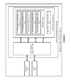
- FIG. 8 illustrates network computer system 800 to integrate IP, HRoT, and NFV systems.
- Network computer system 800 is an example of IP routers 101 - 104 and 401 - 402 , Ethernet switches 403 - 404 , and SDN flow controllers 601 - 602 , although these systems may use alternative configurations and operations.
- Network computer system 800 comprises data processing system 803 , Layer 2 receivers 821 - 824 , and Layer 2 transmitters 825 - 828 .
- Communication receivers 821 - 824 and transmitters 825 - 828 comprise physical ports, digital signal processors, memory devices, software, bus interfaces, and the like.
- Communication receivers 821 - 824 and transmitters 825 - 828 exchange IP packets having HRoT/NFV reporting parameters and response data.
- Data processing system 803 comprises processing circuitry 804 and storage system 805 .
- HRoT key 815 is physically embedded in an electronically readable form from processing circuitry 804 .
- Storage system 805 stores software 806 and IP route information 814 .
- Software 806 includes software modules 811 - 813 .
- Some conventional aspects of computer system 800 are omitted for clarity, such as power supplies, enclosures, and the like.
- Network computer system 800 may be centralized or distributed.
- processing circuitry 804 comprises server blades, circuit boards, bus interfaces and connections, integrated circuitry, and associated electronics.
- Storage system 805 comprises non-transitory, machine-readable, data storage media, such as flash drives, disc drives, memory circuitry, tape drives, servers, and the like.
- Software 806 comprises machine-readable instructions that control the operation of processing circuitry 804 when executed.
- Software 806 includes software modules 811 - 813 and may also include operating systems, applications, data structures, virtual machines, utilities, databases, and the like. All or portions of software 806 may be externally stored on one or more storage media, such as circuitry, discs, tape, and the like.
- HRoT module 811 When executed by processing circuitry 804 , HRoT module 811 directs circuitry 804 to maintain HRoT with the hardware comprising each of receivers 821 - 824 and transmitters 825 - 828 . HRoT module 811 also directs circuitry 804 to provide an encoded version of HRoT key 815 to hypervisor module 812 and/or IP router modules 813 . HRoT module 811 also directs circuitry 804 to execute hypervisor module 812 . When executed by processing circuitry 804 , hypervisor module 812 directs circuitry 804 to operate an NFV data processing environment for IP router modules 813 and to supply NFV time slice data and perhaps encoded HRoT key 815 .
- IP router modules 813 When executed by processing circuitry 804 in the NFV time slices, IP router modules 813 direct circuitry 804 to transfer IP packets from Layer 2 receivers 821 - 824 to Layer 2 transmitters 825 - 828 based on IP addresses and IP route information 814 . Responsive to HRoT/NFV reporting parameters in the IP headers, IP router modules 813 also direct circuitry 804 to obtain encoded HRoT key 815 from HRoT module 811 (through hypervisor module 812 ) and obtain NFV time slice data from hypervisor module 812 .
- IP router modules 813 Responsive to HRoT/NFV reporting parameters in the IP headers, IP router modules 813 also direct circuitry 804 to generate and transfer IP response messages indicating the encoded HRoT key 815 , the NFV time slice data, and the individual Layer 2 receivers and transmitters used for the IP packet transfer.
- FIG. 9 illustrates network computer system 900 to integrate IP, HRoT, and NFV systems.
- Network computer system 900 is an example of probe systems 161 - 162 , 461 - 462 , and 661 - 662 , although these systems may use alternative configurations and operations.
- Network computer system 900 comprises data processing system 903 , Layer 2 receiver 901 , and Layer 2 transmitter 902 .
- Layer 2 receiver 901 and transmitter 902 comprise physical ports, digital signal processors, memory devices, software, bus interfaces, and the like.
- Layer 2 receiver 901 and transmitter 902 exchange IP packets having HRoT/NFV reporting parameters and response data.
- Data processing system 903 comprises processing circuitry 904 and storage system 905 .
- Storage system 905 stores software 906 and network topology data 916 .
- Software 906 includes software modules 911 - 915 .
- Some conventional aspects of computer system 900 are omitted for clarity, such as power supplies, enclosures, and the like.
- Network computer system 900 may be centralized or distributed.
- processing circuitry 904 comprises server blades, circuit boards, bus interfaces and connections, integrated circuitry, and associated electronics.
- Storage system 905 comprises non-transitory, machine-readable, data storage media, such as flash drives, disc drives, memory circuitry, tape drives, servers, and the like.
- Software 906 comprises machine-readable instructions that control the operation of processing circuitry 904 when executed.
- Software 906 includes software modules 911 - 915 and may also include operating systems, applications, data structures, virtual machines, utilities, databases, and the like. All or portions of software 906 may be externally stored on one or more storage media, such as circuitry, discs, tape, and the like.
- IP address allocation module 911 identifies IP address pairs for HRoT and NFV verification.
- probe messaging module 912 directs circuitry 904 to transmit IP probe packets having the identified IP address pair and HRoT/NFV reporting parameters.
- IP communication path module 913 directs circuitry 904 to identify IP communication paths based on received probe response messages and network topology data 916 .
- HRoT verification module 914 directs circuitry 904 to generate HRoT results for the network elements on the IP communications path and compare them to the reported and encoded HRoT HW IDs.
- HRoT verification module 914 also directs circuitry 904 to match the reported communication interfaces to the network topology data 916 to account for all IP probe packet transfers.
- NFV verification module 915 directs circuitry 904 to compare reported NFV time slices for reporting routers, switches, and controllers to their target time slices as indicated by network topology data 916 .
Abstract
Description
Claims (20)
Priority Applications (2)
| Application Number | Priority Date | Filing Date | Title |
|---|---|---|---|
| US14/662,870 US9509587B1 (en) | 2015-03-19 | 2015-03-19 | Hardware root of trust (HROT) for internet protocol (IP) communications |
| US15/333,163 US9843581B2 (en) | 2015-03-19 | 2016-10-24 | Hardware root of trust (HROT) for software-defined network (SDN) communications |
Applications Claiming Priority (1)
| Application Number | Priority Date | Filing Date | Title |
|---|---|---|---|
| US14/662,870 US9509587B1 (en) | 2015-03-19 | 2015-03-19 | Hardware root of trust (HROT) for internet protocol (IP) communications |
Related Child Applications (1)
| Application Number | Title | Priority Date | Filing Date |
|---|---|---|---|
| US15/333,163 Continuation US9843581B2 (en) | 2015-03-19 | 2016-10-24 | Hardware root of trust (HROT) for software-defined network (SDN) communications |
Publications (1)
| Publication Number | Publication Date |
|---|---|
| US9509587B1 true US9509587B1 (en) | 2016-11-29 |
Family
ID=57352081
Family Applications (2)
| Application Number | Title | Priority Date | Filing Date |
|---|---|---|---|
| US14/662,870 Active 2035-05-27 US9509587B1 (en) | 2015-03-19 | 2015-03-19 | Hardware root of trust (HROT) for internet protocol (IP) communications |
| US15/333,163 Active US9843581B2 (en) | 2015-03-19 | 2016-10-24 | Hardware root of trust (HROT) for software-defined network (SDN) communications |
Family Applications After (1)
| Application Number | Title | Priority Date | Filing Date |
|---|---|---|---|
| US15/333,163 Active US9843581B2 (en) | 2015-03-19 | 2016-10-24 | Hardware root of trust (HROT) for software-defined network (SDN) communications |
Country Status (1)
| Country | Link |
|---|---|
| US (2) | US9509587B1 (en) |
Cited By (22)
| Publication number | Priority date | Publication date | Assignee | Title |
|---|---|---|---|---|
| US20170048242A1 (en) * | 2015-03-19 | 2017-02-16 | Sprint Communications Company L.P. | Hardware root of trust (hrot) for software-defined network (sdn) communications |
| US9749294B1 (en) * | 2015-09-08 | 2017-08-29 | Sprint Communications Company L.P. | System and method of establishing trusted operability between networks in a network functions virtualization environment |
| US9769854B1 (en) | 2013-02-07 | 2017-09-19 | Sprint Communications Company L.P. | Trusted signaling in 3GPP interfaces in a network function virtualization wireless communication system |
| US9781016B1 (en) | 2015-11-02 | 2017-10-03 | Sprint Communications Company L.P. | Dynamic addition of network function services |
| US9811686B1 (en) | 2015-10-09 | 2017-11-07 | Sprint Communications Company L.P. | Support systems interactions with virtual network functions in a trusted security zone |
| US9871768B1 (en) | 2015-07-07 | 2018-01-16 | Spring Communications Company L.P. | IPv6 to IPv4 data packet migration in a trusted security zone |
| CN108881241A (en) * | 2018-06-26 | 2018-11-23 | 华中科技大学 | A kind of software-oriented defines the dynamic source address verification method of network |
| CN109150895A (en) * | 2018-09-13 | 2019-01-04 | 清华大学 | A kind of verification method of the intra-domain source addresses of software defined network |
| US10250498B1 (en) | 2016-10-03 | 2019-04-02 | Sprint Communications Company L.P. | Session aggregator brokering of data stream communication |
| US10256994B2 (en) * | 2017-01-12 | 2019-04-09 | Red Hat Israel, Ltd. | Open virtualized multitenant network scheme servicing virtual machine and container based connectivity |
| US10348488B1 (en) | 2017-08-25 | 2019-07-09 | Sprint Communications Company L.P. | Tiered distributed ledger technology (DLT) in a network function virtualization (NFV) core network |
| US10542115B1 (en) | 2015-10-01 | 2020-01-21 | Sprint Communications Company L.P. | Securing communications in a network function virtualization (NFV) core network |
| US10824454B2 (en) | 2017-06-15 | 2020-11-03 | At&T Intellectual Property I, L.P. | 5G dynamic slice and network identity instantiation, termination, and access management system and method |
| US11039359B1 (en) * | 2019-11-19 | 2021-06-15 | Sprint Communications Company L.P. | Wireless communication device handovers between wireless communication network slices |
| US11178159B2 (en) * | 2018-09-07 | 2021-11-16 | Raytheon Company | Cross-domain solution using network-connected hardware root-of-trust device |
| US11347861B2 (en) | 2018-04-10 | 2022-05-31 | Raytheon Company | Controlling security state of commercial off the shelf (COTS) system |
| US11379588B2 (en) | 2019-12-20 | 2022-07-05 | Raytheon Company | System validation by hardware root of trust (HRoT) device and system management mode (SMM) |
| US11423150B2 (en) | 2018-09-07 | 2022-08-23 | Raytheon Company | System and method for booting processors with encrypted boot image |
| US11487872B2 (en) | 2018-12-07 | 2022-11-01 | Hewlett Packard Enterprise Development Lp | Detection of hardware security attacks |
| US11513698B2 (en) | 2019-04-01 | 2022-11-29 | Raytheon Company | Root of trust assisted access control of secure encrypted drives |
| US11595411B2 (en) | 2019-04-01 | 2023-02-28 | Raytheon Company | Adaptive, multi-layer enterprise data protection and resiliency platform |
| US11847205B1 (en) | 2020-10-26 | 2023-12-19 | T-Mobile Innovations Llc | Trusted 5G network function virtualization of virtual network function elements embedded on a system-on-chip |
Families Citing this family (4)
| Publication number | Priority date | Publication date | Assignee | Title |
|---|---|---|---|---|
| US20180302305A1 (en) * | 2017-04-12 | 2018-10-18 | Futurewei Technologies, Inc. | Data center automated network troubleshooting system |
| CN110537352B (en) * | 2017-04-13 | 2022-12-09 | 诺基亚技术有限公司 | Apparatus, method, and non-transitory computer-readable medium for trust management in software defined networks |
| FR3081654A1 (en) * | 2018-06-22 | 2019-11-29 | Orange | METHOD, DEVICE AND SERVER FOR SECURED DISTRIBUTION OF CONFIGURATION TO TERMINAL |
| CN110602150B (en) * | 2019-10-16 | 2021-11-16 | 超越科技股份有限公司 | Trusted authentication method between SDN nodes |
Citations (13)
| Publication number | Priority date | Publication date | Assignee | Title |
|---|---|---|---|---|
| US20060143304A1 (en) | 2002-10-07 | 2006-06-29 | Bodlaender Maarten P | Method of and system for establishing a communication address of a device |
| US20080005562A1 (en) * | 2005-12-13 | 2008-01-03 | Microsoft Corporation | Public key infrastructure certificate entrustment |
| US20080232269A1 (en) | 2007-03-23 | 2008-09-25 | Tatman Lance A | Data collection system and method for ip networks |
| US20090204964A1 (en) * | 2007-10-12 | 2009-08-13 | Foley Peter F | Distributed trusted virtualization platform |
| US7729292B2 (en) | 2005-04-04 | 2010-06-01 | Apple Inc. | Method and apparatus for detecting a router that improperly responds to ARP requests |
| US20100274550A1 (en) | 2008-01-24 | 2010-10-28 | National Chung Cheng University | Integrated development structure having virtual inputs/outputs for embedded hardware/software |
| US20120102334A1 (en) * | 2008-11-24 | 2012-04-26 | Certicom Corp. | System and Method for Hardware Based Security |
| US20130061293A1 (en) * | 2011-09-02 | 2013-03-07 | Wenbo Mao | Method and apparatus for securing the full lifecycle of a virtual machine |
| US8533828B2 (en) * | 2003-01-21 | 2013-09-10 | Hewlett-Packard Development Company, L.P. | System for protecting security of a provisionable network |
| WO2014110453A1 (en) | 2013-01-11 | 2014-07-17 | Huawei Technologies Co., Ltd. | Network function virtualization for a network device |
| US20140229945A1 (en) | 2013-02-12 | 2014-08-14 | Contextream Ltd. | Network control using software defined flow mapping and virtualized network functions |
| US20140241247A1 (en) | 2011-08-29 | 2014-08-28 | Telefonaktiebolaget L M Ericsson (Publ) | Implementing a 3g packet core in a cloud computer with openflow data and control planes |
| US9317708B2 (en) * | 2008-08-14 | 2016-04-19 | Teleputers, Llc | Hardware trust anchors in SP-enabled processors |
Family Cites Families (12)
| Publication number | Priority date | Publication date | Assignee | Title |
|---|---|---|---|---|
| US7634807B2 (en) * | 2003-08-08 | 2009-12-15 | Nokia Corporation | System and method to establish and maintain conditional trust by stating signal of distrust |
| US8589541B2 (en) * | 2009-01-28 | 2013-11-19 | Headwater Partners I Llc | Device-assisted services for protecting network capacity |
| CN101345660B (en) * | 2008-08-21 | 2010-06-09 | 西安西电捷通无线网络通信有限公司 | Reliable network management method based on TCPA/TCG reliable network connection |
| US9270559B2 (en) * | 2009-01-28 | 2016-02-23 | Headwater Partners I Llc | Service policy implementation for an end-user device having a control application or a proxy agent for routing an application traffic flow |
| US8893009B2 (en) * | 2009-01-28 | 2014-11-18 | Headwater Partners I Llc | End user device that secures an association of application to service policy with an application certificate check |
| US8505103B2 (en) * | 2009-09-09 | 2013-08-06 | Fujitsu Limited | Hardware trust anchor |
| US9201131B2 (en) * | 2010-11-18 | 2015-12-01 | The Boeing Company | Secure routing based on degree of trust |
| US9578664B1 (en) * | 2013-02-07 | 2017-02-21 | Sprint Communications Company L.P. | Trusted signaling in 3GPP interfaces in a network function virtualization wireless communication system |
| US9161227B1 (en) * | 2013-02-07 | 2015-10-13 | Sprint Communications Company L.P. | Trusted signaling in long term evolution (LTE) 4G wireless communication |
| JP6481900B2 (en) * | 2014-06-25 | 2019-03-13 | インテル・コーポレーション | Hardware configuration reporting apparatus, hardware configuration arbitration method, program, machine-readable recording medium, and hardware configuration arbitration apparatus |
| US9560078B2 (en) * | 2015-02-04 | 2017-01-31 | Intel Corporation | Technologies for scalable security architecture of virtualized networks |
| US9509587B1 (en) * | 2015-03-19 | 2016-11-29 | Sprint Communications Company L.P. | Hardware root of trust (HROT) for internet protocol (IP) communications |
-
2015
- 2015-03-19 US US14/662,870 patent/US9509587B1/en active Active
-
2016
- 2016-10-24 US US15/333,163 patent/US9843581B2/en active Active
Patent Citations (15)
| Publication number | Priority date | Publication date | Assignee | Title |
|---|---|---|---|---|
| US20060143304A1 (en) | 2002-10-07 | 2006-06-29 | Bodlaender Maarten P | Method of and system for establishing a communication address of a device |
| US8533828B2 (en) * | 2003-01-21 | 2013-09-10 | Hewlett-Packard Development Company, L.P. | System for protecting security of a provisionable network |
| US7729292B2 (en) | 2005-04-04 | 2010-06-01 | Apple Inc. | Method and apparatus for detecting a router that improperly responds to ARP requests |
| US20080005562A1 (en) * | 2005-12-13 | 2008-01-03 | Microsoft Corporation | Public key infrastructure certificate entrustment |
| US20080232269A1 (en) | 2007-03-23 | 2008-09-25 | Tatman Lance A | Data collection system and method for ip networks |
| US20090204964A1 (en) * | 2007-10-12 | 2009-08-13 | Foley Peter F | Distributed trusted virtualization platform |
| US20100274550A1 (en) | 2008-01-24 | 2010-10-28 | National Chung Cheng University | Integrated development structure having virtual inputs/outputs for embedded hardware/software |
| US9317708B2 (en) * | 2008-08-14 | 2016-04-19 | Teleputers, Llc | Hardware trust anchors in SP-enabled processors |
| US20120102334A1 (en) * | 2008-11-24 | 2012-04-26 | Certicom Corp. | System and Method for Hardware Based Security |
| US20140241247A1 (en) | 2011-08-29 | 2014-08-28 | Telefonaktiebolaget L M Ericsson (Publ) | Implementing a 3g packet core in a cloud computer with openflow data and control planes |
| US20130061293A1 (en) * | 2011-09-02 | 2013-03-07 | Wenbo Mao | Method and apparatus for securing the full lifecycle of a virtual machine |
| WO2014110453A1 (en) | 2013-01-11 | 2014-07-17 | Huawei Technologies Co., Ltd. | Network function virtualization for a network device |
| US20140201374A1 (en) | 2013-01-11 | 2014-07-17 | Futurewei Technologies, Inc. | Network Function Virtualization for a Network Device |
| US20140229945A1 (en) | 2013-02-12 | 2014-08-14 | Contextream Ltd. | Network control using software defined flow mapping and virtualized network functions |
| WO2014125486A1 (en) | 2013-02-12 | 2014-08-21 | Contextream Ltd. | Network control using software defined flow mapping and virtualized network functions |
Cited By (28)
| Publication number | Priority date | Publication date | Assignee | Title |
|---|---|---|---|---|
| US9769854B1 (en) | 2013-02-07 | 2017-09-19 | Sprint Communications Company L.P. | Trusted signaling in 3GPP interfaces in a network function virtualization wireless communication system |
| US20170048242A1 (en) * | 2015-03-19 | 2017-02-16 | Sprint Communications Company L.P. | Hardware root of trust (hrot) for software-defined network (sdn) communications |
| US9843581B2 (en) * | 2015-03-19 | 2017-12-12 | Sprint Communications Company L.P. | Hardware root of trust (HROT) for software-defined network (SDN) communications |
| US9871768B1 (en) | 2015-07-07 | 2018-01-16 | Spring Communications Company L.P. | IPv6 to IPv4 data packet migration in a trusted security zone |
| US9749294B1 (en) * | 2015-09-08 | 2017-08-29 | Sprint Communications Company L.P. | System and method of establishing trusted operability between networks in a network functions virtualization environment |
| US9979699B1 (en) | 2015-09-08 | 2018-05-22 | Sprint Communications Company L.P. | System and method of establishing trusted operability between networks in a network functions virtualization environment |
| US11363114B1 (en) | 2015-10-01 | 2022-06-14 | Sprint Communications Company L.P. | Securing communications in a network function virtualization (NFV) core network |
| US10542115B1 (en) | 2015-10-01 | 2020-01-21 | Sprint Communications Company L.P. | Securing communications in a network function virtualization (NFV) core network |
| US9811686B1 (en) | 2015-10-09 | 2017-11-07 | Sprint Communications Company L.P. | Support systems interactions with virtual network functions in a trusted security zone |
| US10044572B1 (en) | 2015-11-02 | 2018-08-07 | Sprint Communications Company L.P. | Dynamic addition of network function services |
| US9781016B1 (en) | 2015-11-02 | 2017-10-03 | Sprint Communications Company L.P. | Dynamic addition of network function services |
| US10536373B1 (en) | 2016-10-03 | 2020-01-14 | Sprint Communications Company L.P. | Session aggregator brokering of data stream communication |
| US10250498B1 (en) | 2016-10-03 | 2019-04-02 | Sprint Communications Company L.P. | Session aggregator brokering of data stream communication |
| US10256994B2 (en) * | 2017-01-12 | 2019-04-09 | Red Hat Israel, Ltd. | Open virtualized multitenant network scheme servicing virtual machine and container based connectivity |
| US10824454B2 (en) | 2017-06-15 | 2020-11-03 | At&T Intellectual Property I, L.P. | 5G dynamic slice and network identity instantiation, termination, and access management system and method |
| US10790965B1 (en) | 2017-08-25 | 2020-09-29 | Sprint Communications Company L.P. | Tiered distributed ledger technology (DLT) in a network function virtualization (NFV) core network |
| US10348488B1 (en) | 2017-08-25 | 2019-07-09 | Sprint Communications Company L.P. | Tiered distributed ledger technology (DLT) in a network function virtualization (NFV) core network |
| US11347861B2 (en) | 2018-04-10 | 2022-05-31 | Raytheon Company | Controlling security state of commercial off the shelf (COTS) system |
| CN108881241A (en) * | 2018-06-26 | 2018-11-23 | 华中科技大学 | A kind of software-oriented defines the dynamic source address verification method of network |
| US11423150B2 (en) | 2018-09-07 | 2022-08-23 | Raytheon Company | System and method for booting processors with encrypted boot image |
| US11178159B2 (en) * | 2018-09-07 | 2021-11-16 | Raytheon Company | Cross-domain solution using network-connected hardware root-of-trust device |
| CN109150895A (en) * | 2018-09-13 | 2019-01-04 | 清华大学 | A kind of verification method of the intra-domain source addresses of software defined network |
| US11487872B2 (en) | 2018-12-07 | 2022-11-01 | Hewlett Packard Enterprise Development Lp | Detection of hardware security attacks |
| US11513698B2 (en) | 2019-04-01 | 2022-11-29 | Raytheon Company | Root of trust assisted access control of secure encrypted drives |
| US11595411B2 (en) | 2019-04-01 | 2023-02-28 | Raytheon Company | Adaptive, multi-layer enterprise data protection and resiliency platform |
| US11039359B1 (en) * | 2019-11-19 | 2021-06-15 | Sprint Communications Company L.P. | Wireless communication device handovers between wireless communication network slices |
| US11379588B2 (en) | 2019-12-20 | 2022-07-05 | Raytheon Company | System validation by hardware root of trust (HRoT) device and system management mode (SMM) |
| US11847205B1 (en) | 2020-10-26 | 2023-12-19 | T-Mobile Innovations Llc | Trusted 5G network function virtualization of virtual network function elements embedded on a system-on-chip |
Also Published As
| Publication number | Publication date |
|---|---|
| US9843581B2 (en) | 2017-12-12 |
| US20170048242A1 (en) | 2017-02-16 |
Similar Documents
| Publication | Publication Date | Title |
|---|---|---|
| US9843581B2 (en) | Hardware root of trust (HROT) for software-defined network (SDN) communications | |
| US11659035B2 (en) | Routing messages between cloud service providers | |
| Azodolmolky et al. | SDN-based cloud computing networking | |
| US9680751B2 (en) | Methods and devices for providing service insertion in a TRILL network | |
| US10616108B2 (en) | Scalable MAC address virtualization | |
| EP3295654B1 (en) | Configuration of network elements for automated policy-based routing | |
| US10003641B2 (en) | Method and system of session-aware load balancing | |
| EP3474521B1 (en) | Cross-stratum optimization protocol | |
| US9473414B2 (en) | Method and system for supporting packet prioritization at a data network | |
| US10050739B2 (en) | Optical communication system with hardware root of trust (HRoT) and network function virtualization (NFV) | |
| US11398956B2 (en) | Multi-Edge EtherChannel (MEEC) creation and management | |
| US20160219076A1 (en) | Hardware trust for integrated network function virtualization (nfv) and software defined network (sdn) systems | |
| EP3251304A1 (en) | Method and apparatus for connecting a gateway router to a set of scalable virtual ip network appliances in overlay networks | |
| US11663052B2 (en) | Adaptive application assignment to distributed cloud resources | |
| US11831549B2 (en) | Device and method for load balancing | |
| US11258720B2 (en) | Flow-based isolation in a service network implemented over a software-defined network | |
| WO2018158615A1 (en) | Method and apparatus for enabling the creation of a point-to-multipoint label switched path multicast distribution tree for a given ip multicast stream | |
| US10944582B2 (en) | Method and apparatus for enhancing multicast group membership protocol(s) |
Legal Events
| Date | Code | Title | Description |
|---|---|---|---|
| AS | Assignment |
Owner name: SPRINT COMMUNICATIONS COMPANY L.P., KANSAS Free format text: ASSIGNMENT OF ASSIGNORS INTEREST;ASSIGNORS:MARQUARDT, RONALD R.;PACZKOWSKI, LYLE WALTER;RAJAGOPAL, ARUN;SIGNING DATES FROM 20150317 TO 20150318;REEL/FRAME:035226/0588 |
|
| STCF | Information on status: patent grant |
Free format text: PATENTED CASE |
|
| AS | Assignment |
Owner name: DEUTSCHE BANK TRUST COMPANY AMERICAS, NEW YORK Free format text: GRANT OF FIRST PRIORITY AND JUNIOR PRIORITY SECURITY INTEREST IN PATENT RIGHTS;ASSIGNOR:SPRINT COMMUNICATIONS COMPANY L.P.;REEL/FRAME:041895/0210 Effective date: 20170203 |
|
| AS | Assignment |
Owner name: SPRINT COMMUNICATIONS COMPANY L.P., KANSAS Free format text: TERMINATION AND RELEASE OF FIRST PRIORITY AND JUNIOR PRIORITY SECURITY INTEREST IN PATENT RIGHTS;ASSIGNOR:DEUTSCHE BANK TRUST COMPANY AMERICAS;REEL/FRAME:052969/0475 Effective date: 20200401 Owner name: DEUTSCHE BANK TRUST COMPANY AMERICAS, NEW YORK Free format text: SECURITY AGREEMENT;ASSIGNORS:T-MOBILE USA, INC.;ISBV LLC;T-MOBILE CENTRAL LLC;AND OTHERS;REEL/FRAME:053182/0001 Effective date: 20200401 |
|
| MAFP | Maintenance fee payment |
Free format text: PAYMENT OF MAINTENANCE FEE, 4TH YEAR, LARGE ENTITY (ORIGINAL EVENT CODE: M1551); ENTITY STATUS OF PATENT OWNER: LARGE ENTITY Year of fee payment: 4 |
|
| AS | Assignment |
Owner name: T-MOBILE INNOVATIONS LLC, KANSAS Free format text: ASSIGNMENT OF ASSIGNORS INTEREST;ASSIGNOR:SPRINT COMMUNICATIONS COMPANY L.P.;REEL/FRAME:055604/0001 Effective date: 20210303 |
|
| AS | Assignment |
Owner name: SPRINT SPECTRUM LLC, KANSAS Free format text: RELEASE BY SECURED PARTY;ASSIGNOR:DEUTSCHE BANK TRUST COMPANY AMERICAS;REEL/FRAME:062595/0001 Effective date: 20220822 Owner name: SPRINT INTERNATIONAL INCORPORATED, KANSAS Free format text: RELEASE BY SECURED PARTY;ASSIGNOR:DEUTSCHE BANK TRUST COMPANY AMERICAS;REEL/FRAME:062595/0001 Effective date: 20220822 Owner name: SPRINT COMMUNICATIONS COMPANY L.P., KANSAS Free format text: RELEASE BY SECURED PARTY;ASSIGNOR:DEUTSCHE BANK TRUST COMPANY AMERICAS;REEL/FRAME:062595/0001 Effective date: 20220822 Owner name: SPRINTCOM LLC, KANSAS Free format text: RELEASE BY SECURED PARTY;ASSIGNOR:DEUTSCHE BANK TRUST COMPANY AMERICAS;REEL/FRAME:062595/0001 Effective date: 20220822 Owner name: CLEARWIRE IP HOLDINGS LLC, KANSAS Free format text: RELEASE BY SECURED PARTY;ASSIGNOR:DEUTSCHE BANK TRUST COMPANY AMERICAS;REEL/FRAME:062595/0001 Effective date: 20220822 Owner name: CLEARWIRE COMMUNICATIONS LLC, KANSAS Free format text: RELEASE BY SECURED PARTY;ASSIGNOR:DEUTSCHE BANK TRUST COMPANY AMERICAS;REEL/FRAME:062595/0001 Effective date: 20220822 Owner name: BOOST WORLDWIDE, LLC, KANSAS Free format text: RELEASE BY SECURED PARTY;ASSIGNOR:DEUTSCHE BANK TRUST COMPANY AMERICAS;REEL/FRAME:062595/0001 Effective date: 20220822 Owner name: ASSURANCE WIRELESS USA, L.P., KANSAS Free format text: RELEASE BY SECURED PARTY;ASSIGNOR:DEUTSCHE BANK TRUST COMPANY AMERICAS;REEL/FRAME:062595/0001 Effective date: 20220822 Owner name: T-MOBILE USA, INC., WASHINGTON Free format text: RELEASE BY SECURED PARTY;ASSIGNOR:DEUTSCHE BANK TRUST COMPANY AMERICAS;REEL/FRAME:062595/0001 Effective date: 20220822 Owner name: T-MOBILE CENTRAL LLC, WASHINGTON Free format text: RELEASE BY SECURED PARTY;ASSIGNOR:DEUTSCHE BANK TRUST COMPANY AMERICAS;REEL/FRAME:062595/0001 Effective date: 20220822 Owner name: PUSHSPRING, LLC, WASHINGTON Free format text: RELEASE BY SECURED PARTY;ASSIGNOR:DEUTSCHE BANK TRUST COMPANY AMERICAS;REEL/FRAME:062595/0001 Effective date: 20220822 Owner name: LAYER3 TV, LLC, WASHINGTON Free format text: RELEASE BY SECURED PARTY;ASSIGNOR:DEUTSCHE BANK TRUST COMPANY AMERICAS;REEL/FRAME:062595/0001 Effective date: 20220822 Owner name: IBSV LLC, WASHINGTON Free format text: RELEASE BY SECURED PARTY;ASSIGNOR:DEUTSCHE BANK TRUST COMPANY AMERICAS;REEL/FRAME:062595/0001 Effective date: 20220822 |