US9480850B2 - Leadless cardiac pacemaker and retrieval device - Google Patents
Leadless cardiac pacemaker and retrieval device Download PDFInfo
- Publication number
- US9480850B2 US9480850B2 US14/451,564 US201414451564A US9480850B2 US 9480850 B2 US9480850 B2 US 9480850B2 US 201414451564 A US201414451564 A US 201414451564A US 9480850 B2 US9480850 B2 US 9480850B2
- Authority
- US
- United States
- Prior art keywords
- grasping mechanism
- docking member
- retrieval
- head portion
- balloon
- Prior art date
- Legal status (The legal status is an assumption and is not a legal conclusion. Google has not performed a legal analysis and makes no representation as to the accuracy of the status listed.)
- Active, expires
Links
Images


Classifications
-
- A—HUMAN NECESSITIES
- A61—MEDICAL OR VETERINARY SCIENCE; HYGIENE
- A61N—ELECTROTHERAPY; MAGNETOTHERAPY; RADIATION THERAPY; ULTRASOUND THERAPY
- A61N1/00—Electrotherapy; Circuits therefor
- A61N1/18—Applying electric currents by contact electrodes
- A61N1/32—Applying electric currents by contact electrodes alternating or intermittent currents
- A61N1/36—Applying electric currents by contact electrodes alternating or intermittent currents for stimulation
- A61N1/372—Arrangements in connection with the implantation of stimulators
- A61N1/375—Constructional arrangements, e.g. casings
- A61N1/3756—Casings with electrodes thereon, e.g. leadless stimulators
-
- A—HUMAN NECESSITIES
- A61—MEDICAL OR VETERINARY SCIENCE; HYGIENE
- A61N—ELECTROTHERAPY; MAGNETOTHERAPY; RADIATION THERAPY; ULTRASOUND THERAPY
- A61N1/00—Electrotherapy; Circuits therefor
- A61N1/18—Applying electric currents by contact electrodes
- A61N1/32—Applying electric currents by contact electrodes alternating or intermittent currents
- A61N1/36—Applying electric currents by contact electrodes alternating or intermittent currents for stimulation
- A61N1/362—Heart stimulators
-
- A—HUMAN NECESSITIES
- A61—MEDICAL OR VETERINARY SCIENCE; HYGIENE
- A61N—ELECTROTHERAPY; MAGNETOTHERAPY; RADIATION THERAPY; ULTRASOUND THERAPY
- A61N1/00—Electrotherapy; Circuits therefor
- A61N1/18—Applying electric currents by contact electrodes
- A61N1/32—Applying electric currents by contact electrodes alternating or intermittent currents
- A61N1/36—Applying electric currents by contact electrodes alternating or intermittent currents for stimulation
- A61N1/372—Arrangements in connection with the implantation of stimulators
- A61N1/37205—Microstimulators, e.g. implantable through a cannula
-
- A—HUMAN NECESSITIES
- A61—MEDICAL OR VETERINARY SCIENCE; HYGIENE
- A61B—DIAGNOSIS; SURGERY; IDENTIFICATION
- A61B17/00—Surgical instruments, devices or methods, e.g. tourniquets
- A61B17/22—Implements for squeezing-off ulcers or the like on the inside of inner organs of the body; Implements for scraping-out cavities of body organs, e.g. bones; Calculus removers; Calculus smashing apparatus; Apparatus for removing obstructions in blood vessels, not otherwise provided for
- A61B17/221—Gripping devices in the form of loops or baskets for gripping calculi or similar types of obstructions
- A61B2017/2215—Gripping devices in the form of loops or baskets for gripping calculi or similar types of obstructions having an open distal end
Definitions
- the disclosure is directed to implantable cardiac devices and associated retrieval devices. More particularly, the disclosure is directed to leadless cardiac stimulators or pacemakers having proximal docking members and associated retrieval devices including retrieval mechanisms configured to engage the docking members.
- Cardiac pacemakers provide electrical stimulation to heart tissue to cause the heart to contract and thus pump blood through the vascular system.
- Conventional pacemakers typically include an electrical lead that extends from a pulse generator implanted subcutaneously or sub-muscularly to an electrode positioned adjacent the inside or outside wall of the cardiac chamber.
- leadless cardiac pacemakers are small capsules typically fixed to an intracardiac implant site in a cardiac chamber with a fixation mechanism engaging the intracardiac tissue.
- the small capsule typically includes bipolar pacing/sensing electrodes, a power source (e.g. a battery), and associated electrical circuitry for controlling the pacing/sensing electrodes, and thus provide electrical stimulation to heart tissue and/or sense a physiological condition.
- the disclosure is directed to several alternative designs, materials and methods of manufacturing medical device structures and assemblies, and uses thereof.
- one illustrative embodiment is an assembly for retrieving an implantable cardiac pacing device.
- the assembly includes an implantable cardiac pacing device and an associated retrieval system.
- the implantable cardiac pacing device has a housing, an electrode positioned proximate a distal end of the housing, and a docking member extending from a proximal end of the housing opposite the distal end
- the docking member includes a head portion and a neck portion extending between the housing and the head portion.
- the retrieval system includes a retrieval catheter and a retrieval device advanceable from the distal end of the retrieval catheter.
- the retrieval device has a grasping mechanism configured to capture the docking member to draw the implantable cardiac pacing device into the lumen of the retrieval catheter.
- the grasping mechanism is expandable from a first position to a second position.
- the grasping mechanism is biased toward the first position in an equilibrium condition.
- the grasping mechanism is configured to surround and pass over the head portion of the docking member in the second position, and be contracted toward the first position to capture the docking member with the grasping mechanism.
- the implantable cardiac pacing device has a housing having a longitudinal axis, an electrode positioned proximate a distal end of the housing, and a docking member extending from a proximal end of the housing opposite the distal end.
- the docking member includes a head portion and a neck portion extending between the housing and the head portion, the head portion having a radial dimension from the longitudinal axis and the neck portion having a radial dimension from the longitudinal axis less than the radial dimension of the head portion.
- the method includes advancing a retrieval system into a heart having the implantable cardiac pacing device implanted therein.
- the retrieval system includes a retrieval catheter having a lumen therein and a retrieval device advanceable from a distal end of the retrieval catheter.
- the retrieval device includes a grasping mechanism expandable from a first position to a second position. The grasping mechanism is biased toward the first position in an equilibrium condition. The grasping mechanism is expanded to the second position and the grasping mechanism is advanced, in the second position, toward the docking member such that the head portion of the docking member passes through an opening of the grasping mechanism. The grasping mechanism is then contracted toward the first position to lock the grasping mechanism to the docking member. The retrieval device is then retracted proximally to draw the implantable cardiac pacing device into the lumen of the retrieval catheter.
- FIG. 1 illustrates an exemplary implantable device implanted in a chamber of a heart and an associated retrieval device retrieving the implantable device during a retrieval procedure;
- FIGS. 2A-2D are perspective views of an exemplary retrieval device and associate method of retrieving an implantable device
- FIGS. 3A-3D are perspective views of another exemplary retrieval device and associate method of retrieving an implantable device
- FIGS. 4A-4D are perspective views of another exemplary retrieval device and associate method of retrieving an implantable device.
- FIGS. 5A-5C are perspective views of another exemplary retrieval device and associate method of retrieving an implantable device.
- an exemplary implantable leadless cardiac pacing device 10 (e.g., a leadless pacemaker) is illustrated implanted in a chamber of a heart H, such as the apex of the right ventricle RV.
- the implantable device 10 may include a shell or housing 12 having a proximal end 14 and a distal end 16 .
- the implantable device 10 may include a first electrode 20 positioned proximate the distal end 16 of the housing 12 and a second electrode 22 positioned proximate the proximal end 14 of the housing 12 .
- the electrodes 20 , 22 may be sensing and/or pacing electrodes to provide electro-therapy and/or sensing capabilities.
- the first electrode 20 may be configured to be positioned against or otherwise contact the cardiac tissue of the heart H while the second electrode 22 may be spaced away from the first electrode 20 , and thus spaced away from the cardiac tissue.
- the implantable device 10 may include a pulse generator (e.g., electrical circuitry) and a power source (e.g., a battery) within the housing 12 to provide electrical signals to the electrodes 20 , 22 and thus control the pacing/sensing electrodes 20 , 22 .
- Electrical communication between pulse generator and the electrodes 20 , 22 may provide electrical stimulation to heart tissue and/or sense a physiological condition.
- the implantable device 10 may include a fixation mechanism 24 proximate the distal end 16 of the housing 12 configured to attach the implantable device 10 to a tissue wall of the heart H, or otherwise anchor the implantable device 10 to the anatomy of the patient.
- the fixation mechanism 24 may include one or more, or a plurality of hooks 26 anchored into the cardiac tissue of the heart H to attach the implantable device 10 to a tissue wall.
- the fixation mechanism 24 may include one or more, or a plurality of passive tines, configured to entangle with trabeculae within the chamber of the heart H and/or a helical fixation anchor configured to be screwed into a tissue wall to anchor the implantable device 10 to the heart H.
- the implantable device 10 may include a docking member 30 proximate the proximal end 14 of the housing 12 configured to facilitate delivery and/or retrieval of the implantable device 10 .
- the docking member 30 may extend from the proximal end 14 of the housing 12 along a longitudinal axis of the housing 12 .
- the docking member 30 may include a head portion 32 and a neck portion 34 extending between the housing 12 and the head portion 32 .
- the head portion 32 may be an enlarged portion relative to the neck portion 34 .
- the head portion 32 may have a radial dimension from the longitudinal axis of the implantable device 10 which is greater than a radial dimension of the neck portion from the longitudinal axis of the implantable device 10 .
- the docking member 30 may be configured to facilitate delivery of the implantable device 10 to the intracardiac site and/or retrieval of the implantable device 10 from the intracardiac site.
- a retrieval system 50 may be advanced into the chamber of the heart H to capture the implantable device 10 and remove the implantable device 10 from the heart H.
- the retrieval system 50 may be advanced into the right ventricle RV of the heart H, using any desired route.
- the retrieval system 50 may be through the femoral vein from a femoral access site, through the inferior vena cava, into the right atrium, and through the tricuspid valve into the right ventricle RV. It is noted, however, other pathways may be implemented, if desired.
- the retrieval system 50 may include a retrieval device 52 advanceable from a lumen of a retrieval catheter 54 .
- the retrieval catheter 54 may include an elongate shaft having an enlarged distal portion to receive the implantable device 10 therein.
- the retrieval system 50 may also include a guide catheter 100 , such as a steerable guide catheter or a guide catheter having a fixed or preset curvature, to facilitate directing the retrieval catheter 54 and/or the retrieval device 52 toward the implantable device 10 in the chamber of the heart H.
- the retrieval device 52 may include a grasping mechanism extending from a distal end of the retrieval device 52 configured to engage the docking member 30 of the implantable device 10 . Once the grasping mechanism of the retrieval device 52 has captured the docking member 30 , the retrieval device 52 may be actuated proximally relative to the retrieval catheter 54 to pull the implantable device 10 into the lumen of the retrieval catheter 54 .
- the enlarged size of the head portion 32 relative to the neck portion 34 may permit the grasping mechanism of the retrieval device 52 to encircle the neck portion 34 below (i.e., distal of) the head portion 32 and retain the loop 122 around the docking member 30 as the retrieval device 52 is pulled proximally.
- the fixation mechanism 24 may disengage from the heart tissue to detach the implantable device 10 from the heart wall.
- the hooks 26 may elongate as the implantable device 10 is drawn proximally into the lumen of the retrieval catheter 54 .
- the grasping mechanism may be expandable from a first position to a second position.
- the grasping mechanism may be configured to be delivered to the chamber of the heart H while in the first position.
- the grasping mechanism may be configured to surround and pass over the head portion 32 of the docking member 30 in the second position, and then contracted toward the first position to capture the docking member 30 with the grasping mechanism.
- the grasping mechanism may be biased toward the first position in an equilibrium condition. In other words, in the absence of an external force, the grasping mechanism may be configured to revert to or toward the first position.
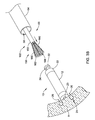
- FIGS. 2A-2D an exemplary embodiment of a retrieval device 52 and associate method of retrieving an implantable device 10 is shown.
- the retrieval device 52 may be extendable distally from a lumen 58 of the retrieval catheter 54 toward the docking member 30 of the implantable device 10 .
- the retrieval device 52 may include an elongate shaft 55 and a grasping mechanism 56 positioned at the distal end of the elongate shaft 55 .
- the grasping mechanism 56 may be expandable from a first position, shown in FIG. 2A , to a second position, shown in FIG. 2B , and then contracted toward the first position, shown in FIG. 2D , to capture the docking member 30 with the grasping mechanism 56 .
- the grasping mechanism 56 may include an inflatable balloon 60 secured to the distal end of the elongate shaft 55 of the retrieval device 52 and a mesh 62 formed of a plurality of filaments surrounding the balloon 60 .
- the filaments of the mesh 62 may be arranged in any desired manner to provide openings between adjacent filaments.
- the filaments may be woven, braided, knitted, or otherwise arranged in an intersecting or interconnected arrangement to provide openings between adjacent filaments.
- the grasping mechanism 56 may be delivered to the chamber of the heart H with the balloon 60 in a deflated state.
- the balloon 60 may be inflated to expand the mesh 62 from the first position to the second position.
- an inflation fluid may be delivered through an inflation lumen 66 extending through the elongate shaft 55 of the retrieval device 52 to the interior of the balloon 60 to inflate the balloon 60 .
- the mesh 62 may be biased toward a contracted configuration in the first position. However, the force exerted on the mesh 62 by the balloon 60 as the balloon 60 is inflated may overcome the biasing forces of the mesh 62 to expand the mesh 62 to the second position.
- the filaments of the mesh 62 may be formed of an elastomeric material, such as an elastomeric polymeric material, permitting the filaments to stretch or elongate when subjected to the forces applied by the balloon 60 . In the absence of the forces applied by the balloon 60 , however, the filaments may contract toward the first position.
- an elastomeric material such as an elastomeric polymeric material
- the grasping mechanism 56 may be advanced distally toward the docking member 30 of the implantable device 10 .
- the head portion 32 of the docking member 30 may pass through an opening between adjacent filaments of the mesh 62 when the mesh 62 is expanded to the second position.
- the head portion 32 may be engaged with the grasping mechanism 56 such that the head portion 32 is positioned within the mesh 62 , yet exterior of the balloon 60 .
- the grasping mechanism 56 may then be contracted toward the first position, as shown in FIG. 2D , to capture the docking member 30 with the grasping mechanism 56 .
- the balloon 60 may then be deflated, as shown in FIG. 2D .
- the mesh 62 may be biased to contract toward the first position to lock the head portion 32 of the docking member 30 in the mesh 62 .
- the opening between adjacent filaments through which the head portion 32 is extended through will be reduced, drawing the filaments into closer contact with the neck portion 34 of the docking member 30 .
- the size of the opening may be reduced to a size less than the size of the head portion 32 such that the head portion 32 cannot pass back out through the opening. Accordingly, contraction of the mesh 62 around the head portion 32 may lock the head portion 32 in the mesh 62 .
- the retrieval device 52 may be actuated proximally relative to the retrieval catheter 54 to draw the implantable cardiac pacing device 10 into the lumen 58 of the retrieval catheter 54 .
- the implantable device 10 retained in the lumen 58 of the retrieval catheter 54 may then be withdrawn from the heart H with the retrieval device 50 , by withdrawing the retrieval device 50 proximally.
- FIGS. 3A-3D Another exemplary embodiment of a retrieval device 152 and associate method of retrieving an implantable device 10 is shown in FIGS. 3A-3D .
- the retrieval device 152 may be extendable distally from a lumen 58 of the retrieval catheter 54 toward the docking member 30 of the implantable device 10 .
- the retrieval device 152 may include an elongate shaft 155 and a grasping mechanism 156 positioned at the distal end of the elongate shaft.
- the grasping mechanism 156 may be expandable from a first position, shown in FIG. 3A , to a second position, shown in FIG. 3B , and then contracted toward the first position, shown in FIG. 3D , to capture the docking member 30 with the grasping mechanism 156 .
- the grasping mechanism 156 may include a plurality of expandable struts 160 secured to the distal end of the elongate shaft 155 of the retrieval device 152 and a resilient annular ring 162 attached to the plurality of expandable struts 160 , such as the distal ends of the plurality of expandable struts 160 .
- the resilient annular ring 162 may lie in a plane perpendicular to the central longitudinal axis of the elongate shaft 155 of the retrieval device 152 and/or may be concentric with the central longitudinal axis of the elongate shaft 155 of the retrieval device 152 .
- the resilient annular ring 162 may be arranged in anther desired orientation with respect to the central longitudinal axis of the elongate shaft 155 .
- the resilient annular ring 162 may be biased toward a contracted configuration in the first position in which the resilient annular ring 162 may have a first diameter.
- the forces exerted on the resilient annular ring 162 by the radial expansion of the struts 160 in a radially outward direction may overcome the biasing forces of the resilient annular ring 162 to expand the resilient annular ring 162 to the second position, as shown in FIG. 3B , in which the resilient annular ring 162 has a second diameter greater than the first diameter.
- the resilient annular ring 162 may be formed of an elastomeric material, such as an elastomeric polymeric material, permitting the resilient annular ring 162 to stretch or elongate when subjected to the radially outward forces applied by the struts 160 . In the absence of the forces applied by the struts 160 , however, the resilient annular ring 162 may contract toward the first position. In other embodiments, the annular ring 162 may be slack or relaxed in the first position.
- the expandable struts 160 may be mechanically actuated to radially expand to the second position, or the expandable struts 160 may be biased to automatically radially expand to the expanded second position when unconstrained. Radial expansion of the expandable struts 160 may exert a sufficient force on the resilient annular ring 162 to overcome the biasing forces of the resilient annular ring 162 to expand the resilient annular ring 162 to the second position. In embodiments in which the annular ring 162 is slack or relaxed in the first position, expansion of the expandable struts 160 may enlarge the annular ring 162 to a taut second position.
- the expandable struts 160 may be constrained by an outer tubular member 153 of the retrieval device 152 to allow the resilient annular ring 162 to assume its contracted configuration in the first position.
- the expandable struts 160 may automatically radially expand to the expanded second position, stretching the resilient annular ring 162 to the second, enlarged diameter in the second position.
- the expandable struts 160 may be radially expanded via actuation of a push/pull wire extending through the elongate shaft 155 , for example, thereby stretching the resilient annular ring 162 to the second, enlarged diameter in the second position.
- the expandable struts 160 may be formed of any desired material providing the struts 160 with a desired flexibility.
- the expandable struts 160 may be formed of a polymeric material or a metallic material, such as stainless steel or a nickel-titanium alloy (e.g., nitinol).
- the expandable struts 160 may have a memorized expanded shape, such that the expandable struts 160 revert to the memorized expanded shape in the absence of a constraining force.
- the grasping mechanism 156 may be advanced distally toward the docking member 30 of the implantable device 10 .
- the head portion 32 of the docking member 30 may pass through an opening 164 through the resilient annular ring 162 when the resilient annular ring 162 is expanded to the second position.
- the head portion 32 may be engaged with the grasping mechanism 156 such that the head portion 32 is positioned through the opening 164 of the resilient annular ring 162 to a position proximal of the resilient annular ring 162 .
- the grasping mechanism 156 may include a mesh covering the openings between adjacent expandable struts 160 , preventing inadvertent or unintentional positioning of the head portion 32 of the docking member 30 through the openings between adjacent struts 160 . Accordingly, the mesh may ensure that the docking member 30 is engaged with the grasping mechanism 156 through the opening 164 .
- the grasping mechanism 156 may then be contracted toward the first position, as shown in FIG. 3D , to capture the docking member 30 with the grasping mechanism 156 .
- the outer tubular member 153 may be moved distally relative to the expandable struts 160 to direct the expandable struts 160 into the distal end of the outer tubular member 153 (e.g., by actuating the outer tubular member 153 distally and/or actuating the expandable struts 160 proximally).
- the forces acting on the expandable struts 160 by the outer tubular member 153 may cause the expandable struts 160 to radially contract toward the contracted first position, permitting the resilient annular ring 162 to revert toward the contracted, first diameter in the first position.
- the expandable struts 160 may be radially contracted via actuation of a push/pull wire extending through the elongate shaft 155 , for example, thereby permitting the resilient annular ring 162 to revert toward the contracted, first diameter in the first position.
- the resilient annular ring 162 will contract toward its equilibrium configuration, reducing the diameter of the opening 164 through which the head portion 32 is extended through, drawing the resilient annular ring 162 into closer contact with the neck portion 34 of the docking member 30 .
- the diameter of the opening 164 of the resilient annular ring 162 may be reduced to a size less than the diameter of the head portion 32 such that the head portion 32 cannot pass back out through the opening 164 . Accordingly, contraction of the resilient annular ring 162 around the head portion 32 may lock the head portion 32 in the grasping mechanism 156 .
- the retrieval device 152 may be actuated proximally relative to the retrieval catheter 54 to draw the implantable cardiac pacing device 10 into the lumen 58 of the retrieval catheter 54 .
- the implantable device 10 retained in the lumen 58 of the retrieval catheter 54 may then be withdrawn from the heart H with the retrieval device 50 , by withdrawing the retrieval device 50 proximally.
- FIGS. 4A-4D Another exemplary embodiment of a retrieval device 252 and associate method of retrieving an implantable device 10 is shown in FIGS. 4A-4D .
- the retrieval device 252 may be extendable distally from a lumen 58 of the retrieval catheter 54 toward the docking member 30 of the implantable device 10 .
- the retrieval device 252 may include an elongate shaft 255 and a grasping mechanism 256 positioned at the distal end of the elongate shaft 255 .
- the grasping mechanism 256 may be expandable from a first position, shown in FIG. 4A , to a second position, shown in FIG. 4B , and then contracted toward the first position, shown in FIG. 4D , to capture the docking member 30 with the grasping mechanism 256 .
- the grasping mechanism 256 may include an inflatable balloon 260 secured to the distal end of the elongate shaft 255 of the retrieval device 252 and a resilient annular ring 262 extending around a distal rim of the balloon 260 .
- the inflatable balloon 260 may include an annular portion defining a distal opening 264 extending proximally into the balloon 260 through the resilient annular ring 262 .
- the inflatable balloon 260 may include an annular portion defining a distal opening extending proximally into the balloon 260 when inflated.
- the inflatable balloon 260 may be conically shaped, flaring outward in a distal direction from the elongate shaft 255 .
- the resilient annular ring 262 may be a monolithic portion of the material of the balloon 260 , however, in other instances the resilient annular ring 262 may be a discrete member attached to the balloon 260 .
- the resilient annular ring 262 may lie in a plane perpendicular to the central longitudinal axis of the elongate shaft 255 of the retrieval device 252 and/or may be concentric with the central longitudinal axis of the elongate shaft 255 of the retrieval device 252 . In other instances, the resilient annular ring 262 may be arranged in anther desired orientation with respect to the central longitudinal axis of the elongate shaft 255 .
- the resilient annular ring 262 may be biased toward a contracted configuration in the first position in which the resilient annular ring 262 may have a first diameter. However, the forces exerted on the resilient annular ring 262 by inflation of the balloon 260 may overcome the biasing forces of the resilient annular ring 262 to expand the resilient annular ring 262 to the second position, as shown in FIG. 4B , in which the resilient annular ring 262 has a second diameter greater than the first diameter.
- the resilient annular ring 262 may be formed of an elastomeric material, such as an elastomeric polymeric material, permitting the resilient annular ring 262 to stretch or elongate when subjected to the radial outward forces applied by inflation of the balloon 260 . In the absence of the inflation forces applied by the inflated balloon 260 , however, the resilient annular ring 262 may contract toward the first position.
- an elastomeric material such as an elastomeric polymeric material
- the grasping mechanism 256 may be delivered to the chamber of the heart H with the balloon 260 in a deflated state.
- the balloon 260 may be inflated to expand or stretch the resilient annular ring 262 from the first position to the second position.
- an inflation fluid may be delivered through an inflation lumen 266 extending through the elongate shaft 255 of the retrieval device 252 to the interior of the balloon 260 to inflate the balloon 260 .
- the resilient annular ring 262 may be biased toward a contracted configuration in the first position.
- the force exerted on the resilient annular ring 262 by the balloon 260 as the balloon 260 is inflated may overcome the biasing forces of the resilient annular ring 262 to expand the resilient annular ring 262 to the second position.
- the resilient annular ring 262 may be formed of an elastomeric material, such as an elastomeric polymeric material, permitting the resilient annular ring 262 to stretch or elongate when subjected to the radially outward forces applied by inflating the balloon 160 . In the absence of the forces applied by inflating the balloon 260 , however, the resilient annular ring 262 may contract toward the first position.
- the grasping mechanism 256 may be advanced distally toward the docking member 30 of the implantable device 10 .
- the head portion 32 of the docking member 30 may pass through the opening 264 through the resilient annular ring 262 when the resilient annular ring 262 is expanded to the second position.
- the head portion 32 may be engaged with the grasping mechanism 256 such that the head portion 32 is positioned through the opening 264 of the resilient annular ring 262 to a position proximal of the resilient annular ring 262 .
- the grasping mechanism 256 may then be contracted toward the first position, as shown in FIG. 4D , to capture the docking member 30 with the grasping mechanism 256 .
- the balloon 260 may then be deflated, as shown in FIG. 4D .
- the resilient annular ring 262 may be biased to contract toward the first position to lock the head portion 32 of the docking member 30 within the opening 264 extending into the balloon 260 proximal of the resilient annular ring 262 .
- the resilient annular ring 262 will contract toward its equilibrium configuration, reducing the diameter of the opening 264 through which the head portion 32 is extended through, drawing the resilient annular ring 262 into closer contact with the neck portion 34 of the docking member 30 .
- the diameter of the opening 264 of the resilient annular ring 262 may be reduced to a size less than the diameter of the head portion 32 such that the head portion 32 cannot pass back out through the opening 264 . Accordingly, contraction of the resilient annular ring 262 around the head portion 32 may lock the head portion 32 in the grasping mechanism 256 .
- the retrieval device 252 may be actuated proximally relative to the retrieval catheter 54 to draw the implantable cardiac pacing device 10 into the lumen 58 of the retrieval catheter 54 .
- the implantable device 10 retained in the lumen 58 of the retrieval catheter 54 may then be withdrawn from the heart H with the retrieval device 50 , by withdrawing the retrieval device 50 proximally.
- FIGS. 5A-5C Another exemplary embodiment of a retrieval device 352 and associate method of retrieving an implantable device 10 is shown in FIGS. 5A-5C .
- the retrieval device 352 may be extendable distally from a lumen 58 of the retrieval catheter 54 toward the docking member 30 of the implantable device 10 .
- the retrieval device 352 may include an elongate shaft 355 and a grasping mechanism 356 positioned at the distal end of the elongate shaft 355 .
- the grasping mechanism 356 may be actuatable from a first position, shown in FIG. 5A , to a second position, shown in FIG. 5C , to capture the docking member 30 with the grasping mechanism 356 .
- the grasping mechanism 356 may include an inflatable balloon 360 secured within the distal end of the elongate shaft 355 of the retrieval device 352 .
- the inflatable balloon 360 which may be an annular balloon, may include an annular portion defining a distal opening 364 extending proximally into the balloon 360 .
- the opening 364 into the annular balloon 360 may have a first diameter in a deflated state, and the opening 364 into the annular balloon 360 may have a second diameter in an inflated state, the second diameter being less than the first diameter.
- the balloon 360 may inflate radially inward when inflated, contracting the opening 364 .
- the grasping mechanism 356 may be delivered to the chamber of the heart H with the balloon 360 in a deflated state, as shown in FIG. 5A .
- the grasping mechanism 356 may be advanced distally toward the docking member 30 of the implantable device 10 with the balloon 360 in the deflated state.
- the head portion 32 of the docking member 30 may pass into or through the opening 364 of the balloon 360 , as shown in FIG. 5B .
- the balloon 360 may be inflated by delivering inflation fluid through the inflation lumen 366 to the balloon 360 to contract the balloon 360 around the head portion 32 and/or neck portion 34 of the docking member 30 , to capture the docking member 30 with the grasping mechanism 356 .
- inflation of the balloon 360 may cause the balloon 360 to expand radially inward, reducing the diameter of the opening 364 through which the head portion 32 is extended through, drawing the annular balloon 360 into closer contact with the head portion 32 and/or neck portion 34 of the docking member 30 .
- the diameter of the opening 364 of the balloon 360 may be reduced to a size less than the diameter of the head portion 32 such that the head portion 32 cannot pass back out through the opening 364 .
- contraction of the annular balloon 360 around the head portion 32 may lock the head portion 32 in the grasping mechanism 356 while the balloon 360 is inflated.
- the retrieval device 352 may be actuated proximally relative to the retrieval catheter 54 to draw the implantable cardiac pacing device 10 into the lumen 58 of the retrieval catheter 54 .
- the implantable device 10 retained in the lumen 58 of the retrieval catheter 54 may then be withdrawn from the heart H with the retrieval device 50 , by withdrawing the retrieval device 50 proximally.
Abstract
A retrieval device and an associated implantable cardiac pacing device. The retrieval device includes a grasping mechanism configured to capture a docking member of the implantable cardiac pacing device to draw the implantable cardiac pacing device into the lumen of a retrieval catheter. The grasping mechanism is expandable from a first position to a second position and is biased toward the first position in an equilibrium condition. The grasping mechanism is configured to surround and pass over a head portion of the docking member in the second position, and be contracted toward the first position to capture the docking member with the grasping mechanism.
Description
This application claims the benefit of U.S. Provisional Application No. 61/866,633 filed Aug. 16, 2013, the complete disclosure of which is herein incorporated by reference.
The disclosure is directed to implantable cardiac devices and associated retrieval devices. More particularly, the disclosure is directed to leadless cardiac stimulators or pacemakers having proximal docking members and associated retrieval devices including retrieval mechanisms configured to engage the docking members.
Cardiac pacemakers provide electrical stimulation to heart tissue to cause the heart to contract and thus pump blood through the vascular system. Conventional pacemakers typically include an electrical lead that extends from a pulse generator implanted subcutaneously or sub-muscularly to an electrode positioned adjacent the inside or outside wall of the cardiac chamber. As an alternative to conventional pacemakers, self-contained or leadless cardiac pacemakers have been proposed. Leadless cardiac pacemakers are small capsules typically fixed to an intracardiac implant site in a cardiac chamber with a fixation mechanism engaging the intracardiac tissue. The small capsule typically includes bipolar pacing/sensing electrodes, a power source (e.g. a battery), and associated electrical circuitry for controlling the pacing/sensing electrodes, and thus provide electrical stimulation to heart tissue and/or sense a physiological condition.
Accordingly, there it is desirable to provide alternative structures, assemblies and systems for retrieving leadless cardiac pacemakers from an implantation site in a heart chamber.
The disclosure is directed to several alternative designs, materials and methods of manufacturing medical device structures and assemblies, and uses thereof.
Accordingly, one illustrative embodiment is an assembly for retrieving an implantable cardiac pacing device. The assembly includes an implantable cardiac pacing device and an associated retrieval system. The implantable cardiac pacing device has a housing, an electrode positioned proximate a distal end of the housing, and a docking member extending from a proximal end of the housing opposite the distal end The docking member includes a head portion and a neck portion extending between the housing and the head portion. The retrieval system includes a retrieval catheter and a retrieval device advanceable from the distal end of the retrieval catheter. The retrieval device has a grasping mechanism configured to capture the docking member to draw the implantable cardiac pacing device into the lumen of the retrieval catheter. The grasping mechanism is expandable from a first position to a second position. The grasping mechanism is biased toward the first position in an equilibrium condition. The grasping mechanism is configured to surround and pass over the head portion of the docking member in the second position, and be contracted toward the first position to capture the docking member with the grasping mechanism.
Another illustrative embodiment is a method of retrieving an implantable cardiac pacing device from a heart. The implantable cardiac pacing device has a housing having a longitudinal axis, an electrode positioned proximate a distal end of the housing, and a docking member extending from a proximal end of the housing opposite the distal end. The docking member includes a head portion and a neck portion extending between the housing and the head portion, the head portion having a radial dimension from the longitudinal axis and the neck portion having a radial dimension from the longitudinal axis less than the radial dimension of the head portion. The method includes advancing a retrieval system into a heart having the implantable cardiac pacing device implanted therein. The retrieval system includes a retrieval catheter having a lumen therein and a retrieval device advanceable from a distal end of the retrieval catheter. The retrieval device includes a grasping mechanism expandable from a first position to a second position. The grasping mechanism is biased toward the first position in an equilibrium condition. The grasping mechanism is expanded to the second position and the grasping mechanism is advanced, in the second position, toward the docking member such that the head portion of the docking member passes through an opening of the grasping mechanism. The grasping mechanism is then contracted toward the first position to lock the grasping mechanism to the docking member. The retrieval device is then retracted proximally to draw the implantable cardiac pacing device into the lumen of the retrieval catheter.
The above summary of some example embodiments is not intended to describe each disclosed embodiment or every implementation of the aspects of the disclosure.
The aspects of the disclosure may be more completely understood in consideration of the following detailed description of various embodiments in connection with the accompanying drawings, in which:
While the aspects of the disclosure are amenable to various modifications and alternative forms, specifics thereof have been shown by way of example in the drawings and will be described in detail. It should be understood, however, that the intention is not to limit aspects of the disclosure to the particular embodiments described. On the contrary, the intention is to cover all modifications, equivalents, and alternatives falling within the spirit and scope of the disclosure.
For the following defined terms, these definitions shall be applied, unless a different definition is given in the claims or elsewhere in this specification.
All numeric values are herein assumed to be modified by the term “about”, whether or not explicitly indicated. The term “about” generally refers to a range of numbers that one of skill in the art would consider equivalent to the recited value (i.e., having the same function or result). In many instances, the term “about” may be indicative as including numbers that are rounded to the nearest significant figure.
The recitation of numerical ranges by endpoints includes all numbers within that range (e.g., 1 to 5 includes 1, 1.5, 2, 2.75, 3, 3.80, 4, and 5).
Although some suitable dimensions, ranges and/or values pertaining to various components, features and/or specifications are disclosed, one of skill in the art, incited by the present disclosure, would understand desired dimensions, ranges and/or values may deviate from those expressly disclosed.
As used in this specification and the appended claims, the singular forms “a”, “an”, and “the” include plural referents unless the content clearly dictates otherwise. As used in this specification and the appended claims, the term “or” is generally employed in its sense including “and/or” unless the content clearly dictates otherwise.
The following detailed description should be read with reference to the drawings in which similar elements in different drawings are numbered the same. The detailed description and the drawings, which are not necessarily to scale, depict illustrative embodiments and are not intended to limit the scope of the disclosure. The illustrative embodiments depicted are intended only as exemplary. Selected features of any illustrative embodiment may be incorporated into an additional embodiment unless clearly stated to the contrary.
Referring to FIG. 1 , an exemplary implantable leadless cardiac pacing device 10 (e.g., a leadless pacemaker) is illustrated implanted in a chamber of a heart H, such as the apex of the right ventricle RV. The implantable device 10 may include a shell or housing 12 having a proximal end 14 and a distal end 16. The implantable device 10 may include a first electrode 20 positioned proximate the distal end 16 of the housing 12 and a second electrode 22 positioned proximate the proximal end 14 of the housing 12. The electrodes 20, 22 may be sensing and/or pacing electrodes to provide electro-therapy and/or sensing capabilities. The first electrode 20 may be configured to be positioned against or otherwise contact the cardiac tissue of the heart H while the second electrode 22 may be spaced away from the first electrode 20, and thus spaced away from the cardiac tissue.
The implantable device 10 may include a pulse generator (e.g., electrical circuitry) and a power source (e.g., a battery) within the housing 12 to provide electrical signals to the electrodes 20, 22 and thus control the pacing/ sensing electrodes 20, 22. Electrical communication between pulse generator and the electrodes 20, 22 may provide electrical stimulation to heart tissue and/or sense a physiological condition.
The implantable device 10 may include a fixation mechanism 24 proximate the distal end 16 of the housing 12 configured to attach the implantable device 10 to a tissue wall of the heart H, or otherwise anchor the implantable device 10 to the anatomy of the patient. As shown in FIG. 1 , in some instances, the fixation mechanism 24 may include one or more, or a plurality of hooks 26 anchored into the cardiac tissue of the heart H to attach the implantable device 10 to a tissue wall. In other instances, the fixation mechanism 24 may include one or more, or a plurality of passive tines, configured to entangle with trabeculae within the chamber of the heart H and/or a helical fixation anchor configured to be screwed into a tissue wall to anchor the implantable device 10 to the heart H.
The implantable device 10 may include a docking member 30 proximate the proximal end 14 of the housing 12 configured to facilitate delivery and/or retrieval of the implantable device 10. For example, the docking member 30 may extend from the proximal end 14 of the housing 12 along a longitudinal axis of the housing 12. The docking member 30 may include a head portion 32 and a neck portion 34 extending between the housing 12 and the head portion 32. The head portion 32 may be an enlarged portion relative to the neck portion 34. For example, the head portion 32 may have a radial dimension from the longitudinal axis of the implantable device 10 which is greater than a radial dimension of the neck portion from the longitudinal axis of the implantable device 10. The docking member 30 may be configured to facilitate delivery of the implantable device 10 to the intracardiac site and/or retrieval of the implantable device 10 from the intracardiac site. Some exemplary embodiments of the docking member 30 are described in further detail herein.
If it is desired to retrieve the implantable device 10 from the heart H, a retrieval system 50 may be advanced into the chamber of the heart H to capture the implantable device 10 and remove the implantable device 10 from the heart H. The retrieval system 50 may be advanced into the right ventricle RV of the heart H, using any desired route. For example, the retrieval system 50 may be through the femoral vein from a femoral access site, through the inferior vena cava, into the right atrium, and through the tricuspid valve into the right ventricle RV. It is noted, however, other pathways may be implemented, if desired.
One exemplary retrieval system 50 is illustrated in FIG. 1 . The retrieval system 50 may include a retrieval device 52 advanceable from a lumen of a retrieval catheter 54. In some instances, as shown in FIG. 1 , the retrieval catheter 54 may include an elongate shaft having an enlarged distal portion to receive the implantable device 10 therein. In some instances, the retrieval system 50 may also include a guide catheter 100, such as a steerable guide catheter or a guide catheter having a fixed or preset curvature, to facilitate directing the retrieval catheter 54 and/or the retrieval device 52 toward the implantable device 10 in the chamber of the heart H.
The retrieval device 52 may include a grasping mechanism extending from a distal end of the retrieval device 52 configured to engage the docking member 30 of the implantable device 10. Once the grasping mechanism of the retrieval device 52 has captured the docking member 30, the retrieval device 52 may be actuated proximally relative to the retrieval catheter 54 to pull the implantable device 10 into the lumen of the retrieval catheter 54. The enlarged size of the head portion 32 relative to the neck portion 34 may permit the grasping mechanism of the retrieval device 52 to encircle the neck portion 34 below (i.e., distal of) the head portion 32 and retain the loop 122 around the docking member 30 as the retrieval device 52 is pulled proximally. As the implantable device 10 is pulled into the retrieval catheter 54, the fixation mechanism 24 may disengage from the heart tissue to detach the implantable device 10 from the heart wall. For example, the hooks 26 may elongate as the implantable device 10 is drawn proximally into the lumen of the retrieval catheter 54.
In some instances, the grasping mechanism may be expandable from a first position to a second position. The grasping mechanism may be configured to be delivered to the chamber of the heart H while in the first position. The grasping mechanism may be configured to surround and pass over the head portion 32 of the docking member 30 in the second position, and then contracted toward the first position to capture the docking member 30 with the grasping mechanism. In some instances, the grasping mechanism may be biased toward the first position in an equilibrium condition. In other words, in the absence of an external force, the grasping mechanism may be configured to revert to or toward the first position.
Turning to FIGS. 2A-2D , an exemplary embodiment of a retrieval device 52 and associate method of retrieving an implantable device 10 is shown. The retrieval device 52 may be extendable distally from a lumen 58 of the retrieval catheter 54 toward the docking member 30 of the implantable device 10. The retrieval device 52 may include an elongate shaft 55 and a grasping mechanism 56 positioned at the distal end of the elongate shaft 55. The grasping mechanism 56 may be expandable from a first position, shown in FIG. 2A , to a second position, shown in FIG. 2B , and then contracted toward the first position, shown in FIG. 2D , to capture the docking member 30 with the grasping mechanism 56.
The grasping mechanism 56 may include an inflatable balloon 60 secured to the distal end of the elongate shaft 55 of the retrieval device 52 and a mesh 62 formed of a plurality of filaments surrounding the balloon 60. The filaments of the mesh 62 may be arranged in any desired manner to provide openings between adjacent filaments. For example, the filaments may be woven, braided, knitted, or otherwise arranged in an intersecting or interconnected arrangement to provide openings between adjacent filaments.
The grasping mechanism 56 may be delivered to the chamber of the heart H with the balloon 60 in a deflated state. As shown in FIG. 2B , the balloon 60 may be inflated to expand the mesh 62 from the first position to the second position. For example, an inflation fluid may be delivered through an inflation lumen 66 extending through the elongate shaft 55 of the retrieval device 52 to the interior of the balloon 60 to inflate the balloon 60. The mesh 62 may be biased toward a contracted configuration in the first position. However, the force exerted on the mesh 62 by the balloon 60 as the balloon 60 is inflated may overcome the biasing forces of the mesh 62 to expand the mesh 62 to the second position. For example, the filaments of the mesh 62 may be formed of an elastomeric material, such as an elastomeric polymeric material, permitting the filaments to stretch or elongate when subjected to the forces applied by the balloon 60. In the absence of the forces applied by the balloon 60, however, the filaments may contract toward the first position.
As shown in FIG. 2C , with the grasping mechanism 56 expanded to the second position, the grasping mechanism 56 may be advanced distally toward the docking member 30 of the implantable device 10. As the grasping mechanism 56 engages the docking member 30, the head portion 32 of the docking member 30 may pass through an opening between adjacent filaments of the mesh 62 when the mesh 62 is expanded to the second position. Thus, the head portion 32 may be engaged with the grasping mechanism 56 such that the head portion 32 is positioned within the mesh 62, yet exterior of the balloon 60.
The grasping mechanism 56 may then be contracted toward the first position, as shown in FIG. 2D , to capture the docking member 30 with the grasping mechanism 56. For example, the balloon 60 may then be deflated, as shown in FIG. 2D . Upon deflation of the balloon 60, the mesh 62 may be biased to contract toward the first position to lock the head portion 32 of the docking member 30 in the mesh 62. In other words, as the mesh 62 contracts around the head portion 32, the opening between adjacent filaments through which the head portion 32 is extended through, will be reduced, drawing the filaments into closer contact with the neck portion 34 of the docking member 30. The size of the opening may be reduced to a size less than the size of the head portion 32 such that the head portion 32 cannot pass back out through the opening. Accordingly, contraction of the mesh 62 around the head portion 32 may lock the head portion 32 in the mesh 62. With the head portion 32 locked in the contracted mesh 62, the retrieval device 52 may be actuated proximally relative to the retrieval catheter 54 to draw the implantable cardiac pacing device 10 into the lumen 58 of the retrieval catheter 54. The implantable device 10, retained in the lumen 58 of the retrieval catheter 54 may then be withdrawn from the heart H with the retrieval device 50, by withdrawing the retrieval device 50 proximally.
Another exemplary embodiment of a retrieval device 152 and associate method of retrieving an implantable device 10 is shown in FIGS. 3A-3D . The retrieval device 152 may be extendable distally from a lumen 58 of the retrieval catheter 54 toward the docking member 30 of the implantable device 10. The retrieval device 152 may include an elongate shaft 155 and a grasping mechanism 156 positioned at the distal end of the elongate shaft. The grasping mechanism 156 may be expandable from a first position, shown in FIG. 3A , to a second position, shown in FIG. 3B , and then contracted toward the first position, shown in FIG. 3D , to capture the docking member 30 with the grasping mechanism 156.
The grasping mechanism 156 may include a plurality of expandable struts 160 secured to the distal end of the elongate shaft 155 of the retrieval device 152 and a resilient annular ring 162 attached to the plurality of expandable struts 160, such as the distal ends of the plurality of expandable struts 160. In some instances, the resilient annular ring 162 may lie in a plane perpendicular to the central longitudinal axis of the elongate shaft 155 of the retrieval device 152 and/or may be concentric with the central longitudinal axis of the elongate shaft 155 of the retrieval device 152. In other instances, the resilient annular ring 162 may be arranged in anther desired orientation with respect to the central longitudinal axis of the elongate shaft 155.
The resilient annular ring 162 may be biased toward a contracted configuration in the first position in which the resilient annular ring 162 may have a first diameter. However, the forces exerted on the resilient annular ring 162 by the radial expansion of the struts 160 in a radially outward direction may overcome the biasing forces of the resilient annular ring 162 to expand the resilient annular ring 162 to the second position, as shown in FIG. 3B , in which the resilient annular ring 162 has a second diameter greater than the first diameter. For example, the resilient annular ring 162 may be formed of an elastomeric material, such as an elastomeric polymeric material, permitting the resilient annular ring 162 to stretch or elongate when subjected to the radially outward forces applied by the struts 160. In the absence of the forces applied by the struts 160, however, the resilient annular ring 162 may contract toward the first position. In other embodiments, the annular ring 162 may be slack or relaxed in the first position.
The expandable struts 160 may be mechanically actuated to radially expand to the second position, or the expandable struts 160 may be biased to automatically radially expand to the expanded second position when unconstrained. Radial expansion of the expandable struts 160 may exert a sufficient force on the resilient annular ring 162 to overcome the biasing forces of the resilient annular ring 162 to expand the resilient annular ring 162 to the second position. In embodiments in which the annular ring 162 is slack or relaxed in the first position, expansion of the expandable struts 160 may enlarge the annular ring 162 to a taut second position.
In some instances the expandable struts 160 may be constrained by an outer tubular member 153 of the retrieval device 152 to allow the resilient annular ring 162 to assume its contracted configuration in the first position. As the outer tubular member 153 is moved proximally relative to the expandable struts 160 to expose the expandable struts 160 from the distal end of the outer tubular member 153 (e.g., by actuating the outer tubular member 153 proximally and/or actuating the expandable struts 160 distally), the expandable struts 160 may automatically radially expand to the expanded second position, stretching the resilient annular ring 162 to the second, enlarged diameter in the second position. In other instances, the expandable struts 160 may be radially expanded via actuation of a push/pull wire extending through the elongate shaft 155, for example, thereby stretching the resilient annular ring 162 to the second, enlarged diameter in the second position. The expandable struts 160 may be formed of any desired material providing the struts 160 with a desired flexibility. For example, the expandable struts 160 may be formed of a polymeric material or a metallic material, such as stainless steel or a nickel-titanium alloy (e.g., nitinol). In some embodiments, the expandable struts 160 may have a memorized expanded shape, such that the expandable struts 160 revert to the memorized expanded shape in the absence of a constraining force.
As shown in FIG. 3C , with the grasping mechanism 156 expanded to the second position, the grasping mechanism 156 may be advanced distally toward the docking member 30 of the implantable device 10. As the grasping mechanism 156 engages the docking member 30, the head portion 32 of the docking member 30 may pass through an opening 164 through the resilient annular ring 162 when the resilient annular ring 162 is expanded to the second position. Thus, the head portion 32 may be engaged with the grasping mechanism 156 such that the head portion 32 is positioned through the opening 164 of the resilient annular ring 162 to a position proximal of the resilient annular ring 162. In some embodiments, such as the embodiment shown in FIGS. 3A-3D , the grasping mechanism 156 may include a mesh covering the openings between adjacent expandable struts 160, preventing inadvertent or unintentional positioning of the head portion 32 of the docking member 30 through the openings between adjacent struts 160. Accordingly, the mesh may ensure that the docking member 30 is engaged with the grasping mechanism 156 through the opening 164.
The grasping mechanism 156 may then be contracted toward the first position, as shown in FIG. 3D , to capture the docking member 30 with the grasping mechanism 156. For example, the outer tubular member 153 may be moved distally relative to the expandable struts 160 to direct the expandable struts 160 into the distal end of the outer tubular member 153 (e.g., by actuating the outer tubular member 153 distally and/or actuating the expandable struts 160 proximally). The forces acting on the expandable struts 160 by the outer tubular member 153 may cause the expandable struts 160 to radially contract toward the contracted first position, permitting the resilient annular ring 162 to revert toward the contracted, first diameter in the first position. In other instances, the expandable struts 160 may be radially contracted via actuation of a push/pull wire extending through the elongate shaft 155, for example, thereby permitting the resilient annular ring 162 to revert toward the contracted, first diameter in the first position. In other words, as the expandable struts 160 are radially contracted, the resilient annular ring 162 will contract toward its equilibrium configuration, reducing the diameter of the opening 164 through which the head portion 32 is extended through, drawing the resilient annular ring 162 into closer contact with the neck portion 34 of the docking member 30. The diameter of the opening 164 of the resilient annular ring 162 may be reduced to a size less than the diameter of the head portion 32 such that the head portion 32 cannot pass back out through the opening 164. Accordingly, contraction of the resilient annular ring 162 around the head portion 32 may lock the head portion 32 in the grasping mechanism 156. With the head portion 32 locked in the grasping mechanism 156 with the contracted resilient annular ring 162, the retrieval device 152 may be actuated proximally relative to the retrieval catheter 54 to draw the implantable cardiac pacing device 10 into the lumen 58 of the retrieval catheter 54. The implantable device 10, retained in the lumen 58 of the retrieval catheter 54 may then be withdrawn from the heart H with the retrieval device 50, by withdrawing the retrieval device 50 proximally.
Another exemplary embodiment of a retrieval device 252 and associate method of retrieving an implantable device 10 is shown in FIGS. 4A-4D . The retrieval device 252 may be extendable distally from a lumen 58 of the retrieval catheter 54 toward the docking member 30 of the implantable device 10. The retrieval device 252 may include an elongate shaft 255 and a grasping mechanism 256 positioned at the distal end of the elongate shaft 255. The grasping mechanism 256 may be expandable from a first position, shown in FIG. 4A , to a second position, shown in FIG. 4B , and then contracted toward the first position, shown in FIG. 4D , to capture the docking member 30 with the grasping mechanism 256.
The grasping mechanism 256 may include an inflatable balloon 260 secured to the distal end of the elongate shaft 255 of the retrieval device 252 and a resilient annular ring 262 extending around a distal rim of the balloon 260. The inflatable balloon 260 may include an annular portion defining a distal opening 264 extending proximally into the balloon 260 through the resilient annular ring 262. In some embodiments, as shown in FIG. 4B , the inflatable balloon 260 may include an annular portion defining a distal opening extending proximally into the balloon 260 when inflated. In some instances, the inflatable balloon 260 may be conically shaped, flaring outward in a distal direction from the elongate shaft 255.
In some instances, the resilient annular ring 262 may be a monolithic portion of the material of the balloon 260, however, in other instances the resilient annular ring 262 may be a discrete member attached to the balloon 260. The resilient annular ring 262 may lie in a plane perpendicular to the central longitudinal axis of the elongate shaft 255 of the retrieval device 252 and/or may be concentric with the central longitudinal axis of the elongate shaft 255 of the retrieval device 252. In other instances, the resilient annular ring 262 may be arranged in anther desired orientation with respect to the central longitudinal axis of the elongate shaft 255.
The resilient annular ring 262 may be biased toward a contracted configuration in the first position in which the resilient annular ring 262 may have a first diameter. However, the forces exerted on the resilient annular ring 262 by inflation of the balloon 260 may overcome the biasing forces of the resilient annular ring 262 to expand the resilient annular ring 262 to the second position, as shown in FIG. 4B , in which the resilient annular ring 262 has a second diameter greater than the first diameter. For example, the resilient annular ring 262 may be formed of an elastomeric material, such as an elastomeric polymeric material, permitting the resilient annular ring 262 to stretch or elongate when subjected to the radial outward forces applied by inflation of the balloon 260. In the absence of the inflation forces applied by the inflated balloon 260, however, the resilient annular ring 262 may contract toward the first position.
The grasping mechanism 256 may be delivered to the chamber of the heart H with the balloon 260 in a deflated state. As shown in FIG. 4B , the balloon 260 may be inflated to expand or stretch the resilient annular ring 262 from the first position to the second position. For example, an inflation fluid may be delivered through an inflation lumen 266 extending through the elongate shaft 255 of the retrieval device 252 to the interior of the balloon 260 to inflate the balloon 260. The resilient annular ring 262 may be biased toward a contracted configuration in the first position. However, the force exerted on the resilient annular ring 262 by the balloon 260 as the balloon 260 is inflated may overcome the biasing forces of the resilient annular ring 262 to expand the resilient annular ring 262 to the second position. For example, the resilient annular ring 262 may be formed of an elastomeric material, such as an elastomeric polymeric material, permitting the resilient annular ring 262 to stretch or elongate when subjected to the radially outward forces applied by inflating the balloon 160. In the absence of the forces applied by inflating the balloon 260, however, the resilient annular ring 262 may contract toward the first position.
As shown in FIG. 4C , with the grasping mechanism 256 expanded to the second position, the grasping mechanism 256 may be advanced distally toward the docking member 30 of the implantable device 10. As the grasping mechanism 256 engages the docking member 30, the head portion 32 of the docking member 30 may pass through the opening 264 through the resilient annular ring 262 when the resilient annular ring 262 is expanded to the second position. Thus, the head portion 32 may be engaged with the grasping mechanism 256 such that the head portion 32 is positioned through the opening 264 of the resilient annular ring 262 to a position proximal of the resilient annular ring 262.
The grasping mechanism 256 may then be contracted toward the first position, as shown in FIG. 4D , to capture the docking member 30 with the grasping mechanism 256. For example, the balloon 260 may then be deflated, as shown in FIG. 4D . Upon deflation of the balloon 260, the resilient annular ring 262 may be biased to contract toward the first position to lock the head portion 32 of the docking member 30 within the opening 264 extending into the balloon 260 proximal of the resilient annular ring 262. In other words, as the balloon 260 is deflated, the resilient annular ring 262 will contract toward its equilibrium configuration, reducing the diameter of the opening 264 through which the head portion 32 is extended through, drawing the resilient annular ring 262 into closer contact with the neck portion 34 of the docking member 30. The diameter of the opening 264 of the resilient annular ring 262 may be reduced to a size less than the diameter of the head portion 32 such that the head portion 32 cannot pass back out through the opening 264. Accordingly, contraction of the resilient annular ring 262 around the head portion 32 may lock the head portion 32 in the grasping mechanism 256. With the head portion 32 locked in the grasping mechanism 256 with the contracted resilient annular ring 262, the retrieval device 252 may be actuated proximally relative to the retrieval catheter 54 to draw the implantable cardiac pacing device 10 into the lumen 58 of the retrieval catheter 54. The implantable device 10, retained in the lumen 58 of the retrieval catheter 54 may then be withdrawn from the heart H with the retrieval device 50, by withdrawing the retrieval device 50 proximally.
Another exemplary embodiment of a retrieval device 352 and associate method of retrieving an implantable device 10 is shown in FIGS. 5A-5C . The retrieval device 352 may be extendable distally from a lumen 58 of the retrieval catheter 54 toward the docking member 30 of the implantable device 10. The retrieval device 352 may include an elongate shaft 355 and a grasping mechanism 356 positioned at the distal end of the elongate shaft 355. The grasping mechanism 356 may be actuatable from a first position, shown in FIG. 5A , to a second position, shown in FIG. 5C , to capture the docking member 30 with the grasping mechanism 356.
The grasping mechanism 356 may include an inflatable balloon 360 secured within the distal end of the elongate shaft 355 of the retrieval device 352. The inflatable balloon 360, which may be an annular balloon, may include an annular portion defining a distal opening 364 extending proximally into the balloon 360. The opening 364 into the annular balloon 360 may have a first diameter in a deflated state, and the opening 364 into the annular balloon 360 may have a second diameter in an inflated state, the second diameter being less than the first diameter. In other words, the balloon 360 may inflate radially inward when inflated, contracting the opening 364.
The grasping mechanism 356 may be delivered to the chamber of the heart H with the balloon 360 in a deflated state, as shown in FIG. 5A . The grasping mechanism 356 may be advanced distally toward the docking member 30 of the implantable device 10 with the balloon 360 in the deflated state. As the grasping mechanism 356 engages the docking member 30, the head portion 32 of the docking member 30 may pass into or through the opening 364 of the balloon 360, as shown in FIG. 5B .
As shown in FIG. 5C , the balloon 360 may be inflated by delivering inflation fluid through the inflation lumen 366 to the balloon 360 to contract the balloon 360 around the head portion 32 and/or neck portion 34 of the docking member 30, to capture the docking member 30 with the grasping mechanism 356. In other words, inflation of the balloon 360 may cause the balloon 360 to expand radially inward, reducing the diameter of the opening 364 through which the head portion 32 is extended through, drawing the annular balloon 360 into closer contact with the head portion 32 and/or neck portion 34 of the docking member 30. The diameter of the opening 364 of the balloon 360 may be reduced to a size less than the diameter of the head portion 32 such that the head portion 32 cannot pass back out through the opening 364. Accordingly, contraction of the annular balloon 360 around the head portion 32 may lock the head portion 32 in the grasping mechanism 356 while the balloon 360 is inflated. With the head portion 32 locked in the grasping mechanism 356 with the inflated annular balloon 360, the retrieval device 352 may be actuated proximally relative to the retrieval catheter 54 to draw the implantable cardiac pacing device 10 into the lumen 58 of the retrieval catheter 54. The implantable device 10, retained in the lumen 58 of the retrieval catheter 54 may then be withdrawn from the heart H with the retrieval device 50, by withdrawing the retrieval device 50 proximally.
Those skilled in the art will recognize that aspects of the present disclosure may be manifested in a variety of forms other than the specific embodiments described and contemplated herein. Accordingly, departure in form and detail may be made without departing from the scope and spirit of the present disclosure as described in the appended claims.
Claims (12)
1. An assembly for retrieving an implantable cardiac pacing device, comprising:
an implantable cardiac pacing device having a housing, an electrode positioned proximate a distal end of the housing, and a docking member extending from a proximal end of the housing opposite the distal end, the docking member including a head portion and a neck portion extending between the housing and the head portion; and
a retrieval system including:
a retrieval catheter having a proximal end, a distal end, and a lumen extending into the retrieval catheter from the distal end; and
a retrieval device advanceable from the distal end of the retrieval catheter, the retrieval device having a grasping mechanism configured to capture the docking member to draw the implantable cardiac pacing device into the lumen of the retrieval catheter;
wherein the grasping mechanism is expandable from a first position to a second position, the grasping mechanism being biased toward the first position in an equilibrium condition;
wherein the grasping mechanism is configured to surround and pass over the head portion of the docking member in the second position, and be contracted toward the first position to capture the docking member with the grasping mechanism;
wherein the grasping mechanism includes an inflatable balloon;
wherein the inflatable balloon includes an annular portion defining a distal opening extending proximally into the balloon; and
wherein the inflatable balloon includes a resilient annular ring extending around a rim of the distal opening.
2. The assembly of claim 1 , wherein the inflatable balloon is conical shaped.
3. The assembly of claim 1 , wherein the balloon is inflatable to expand the resilient annular ring to the second position to permit the head portion of the docking member to pass through the resilient annular ring into the distal opening of the balloon.
4. The assembly of claim 3 , wherein upon deflation of the balloon, the resilient annular ring is biased to contract toward the first position around the neck portion of the docking member to lock the docking member in the annular portion of the balloon.
5. The assembly of claim 1 , wherein the retrieval device includes an inflatable lumen configured to delivery inflation fluid to the inflatable balloon.
6. An assembly for retrieving an implantable cardiac pacing device, comprising:
an implantable cardiac pacing device having a housing, an electrode positioned proximate a distal end of the housing, and a docking member extending from a proximal end of the housing opposite the distal end, the docking member including a head portion and a neck portion extending between the housing and the head portion; and
a retrieval system including:
a retrieval catheter having a proximal end, a distal end, and a lumen extending into the retrieval catheter from the distal end; and
a retrieval device advanceable from the distal and of the retrieval catheter, the retrieval device having a grasping mechanism configured to capture the docking member to draw the implantable cardiac pacing device into the lumen of the retrieval catheter;
wherein the grasping mechanism is expandable from a first position to a second position, the grasping mechanism being biased toward the first position in an equilibrium condition;
wherein the grasping mechanism is configured to surround and pass over the head portion of the docking member in the second position; and be contracted toward the first position to capture the docking member with the grasping mechanism;
wherein the grasping mechanism includes an inflatable balloon and a mesh formed of a plurality of filaments surrounding the balloon.
7. The assembly of claim 6 , wherein the balloon is inflatable to expand the mesh to the second position to permit the head portion of the docking member to pass through an opening between adjacent filaments of the mesh.
8. The assembly of claim 7 , wherein upon deflation of the balloon, the mesh is biased to contract toward the first position to lock the head portion of the docking member in the mesh.
9. An assembly for retrieving an implantable cardiac pacing device, comprising:
an implantable cardiac pacing device having a housing, an electrode positioned proximate a distal end of the housing, and a docking member extending from a proximal end of the housing opposite the distal end, the docking member including a head portion and a neck portion extending between the housing and the head portion; and
a retrieval system including:
a retrieval catheter having a proximal end, a distal end, and a lumen extending into the retrieval catheter from the distal end; and
a retrieval device advanceable from the distal end of the retrieval catheter, the retrieval device having a grasping mechanism configured to capture the docking member to draw the implantable cardiac pacing device into the lumen of the retrieval catheter:
wherein the grasping mechanism is expandable from a first position to a second position, the grasping mechanism being biased toward the first position in an equilibrium condition;
wherein the grasping mechanism is configured to surround and pass over the head portion of the docking member in the second position, and be contracted toward the first position to capture the docking member with the grasping mechanism; and
wherein the grasping mechanism includes a plurality of expandable struts and a resilient annular ring attached to the plurality of expandable struts.
10. The assembly of claim 9 , wherein the plurality of struts are expandable to expand the resilient annular ring to the second position to permit the head portion of the docking member to pass proximally through the resilient annular ring.
11. The assembly of claim 10 , wherein the resilient annular ring is biased to contract toward the first position around the neck portion of the docking member to lock the grasping mechanism to the docking member.
12. The assembly of claim 9 , further comprising a mesh covering opening between adjacent struts.
Priority Applications (1)
| Application Number | Priority Date | Filing Date | Title |
|---|---|---|---|
| US14/451,564 US9480850B2 (en) | 2013-08-16 | 2014-08-05 | Leadless cardiac pacemaker and retrieval device |
Applications Claiming Priority (2)
| Application Number | Priority Date | Filing Date | Title |
|---|---|---|---|
| US201361866633P | 2013-08-16 | 2013-08-16 | |
| US14/451,564 US9480850B2 (en) | 2013-08-16 | 2014-08-05 | Leadless cardiac pacemaker and retrieval device |
Publications (2)
| Publication Number | Publication Date |
|---|---|
| US20150051610A1 US20150051610A1 (en) | 2015-02-19 |
| US9480850B2 true US9480850B2 (en) | 2016-11-01 |
Family
ID=52467333
Family Applications (1)
| Application Number | Title | Priority Date | Filing Date |
|---|---|---|---|
| US14/451,564 Active 2035-02-12 US9480850B2 (en) | 2013-08-16 | 2014-08-05 | Leadless cardiac pacemaker and retrieval device |
Country Status (1)
| Country | Link |
|---|---|
| US (1) | US9480850B2 (en) |
Cited By (11)
| Publication number | Priority date | Publication date | Assignee | Title |
|---|---|---|---|---|
| US20170095662A1 (en) * | 2015-10-01 | 2017-04-06 | Medtronic, Inc. | Interventional medical systems, catheters, and methods |
| US20170100582A1 (en) * | 2015-10-12 | 2017-04-13 | Medtronic, Inc. | Interventional medical systems, catheters, and subassemblies |
| US10080888B2 (en) | 2015-11-16 | 2018-09-25 | Medtronic, Inc. | Interventional medical systems and associated methods |
| USD894396S1 (en) | 2019-03-08 | 2020-08-25 | Pacesetter, Inc. | Leadless biostimulator attachment feature |
| US11090081B2 (en) | 2015-07-10 | 2021-08-17 | Medtronic, Inc. | Extravascular medical access tools having boring tip and methods of using such tools |
| US11141597B2 (en) | 2018-03-09 | 2021-10-12 | Pacesetter, Inc. | Leadless pacemaker having attachment feature |
| US11382663B2 (en) | 2019-05-03 | 2022-07-12 | Pacesetter, Inc. | Biostimulator retrieval system having cincher tube |
| US11446510B2 (en) | 2019-03-29 | 2022-09-20 | Cardiac Pacemakers, Inc. | Systems and methods for treating cardiac arrhythmias |
| US11510697B2 (en) | 2019-09-11 | 2022-11-29 | Cardiac Pacemakers, Inc. | Tools and systems for implanting and/or retrieving a leadless cardiac pacing device with helix fixation |
| US11571582B2 (en) | 2019-09-11 | 2023-02-07 | Cardiac Pacemakers, Inc. | Tools and systems for implanting and/or retrieving a leadless cardiac pacing device with helix fixation |
| US11833349B2 (en) | 2019-03-29 | 2023-12-05 | Cardiac Pacemakers, Inc. | Systems and methods for treating cardiac arrhythmias |
Families Citing this family (108)
| Publication number | Priority date | Publication date | Assignee | Title |
|---|---|---|---|---|
| WO2015106015A1 (en) | 2014-01-10 | 2015-07-16 | Cardiac Pacemakers, Inc. | Systems and methods for detecting cardiac arrhythmias |
| EP3308833B1 (en) | 2014-01-10 | 2019-06-26 | Cardiac Pacemakers, Inc. | Methods and systems for improved communication between medical devices |
| US10080887B2 (en) | 2014-04-29 | 2018-09-25 | Cardiac Pacemakers, Inc. | Leadless cardiac pacing devices including tissue engagement verification |
| WO2015168155A1 (en) | 2014-04-29 | 2015-11-05 | Cardiac Pacemakers, Inc. | Leadless cardiac pacemaker with retrieval features |
| US9539423B2 (en) * | 2014-07-17 | 2017-01-10 | Medtronic, Inc. | Interventional medical systems, tools, and methods of use |
| EP3185952B1 (en) | 2014-08-28 | 2018-07-25 | Cardiac Pacemakers, Inc. | Implantable cardiac rhythm system and an associated method for triggering a blanking period through a second device |
| WO2016073509A1 (en) | 2014-11-04 | 2016-05-12 | Cardiac Pacemakers, Inc. | Implantable medical devices and methods for making and delivering implantable medical devices |
| WO2016126613A1 (en) | 2015-02-06 | 2016-08-11 | Cardiac Pacemakers, Inc. | Systems and methods for treating cardiac arrhythmias |
| WO2016126968A1 (en) | 2015-02-06 | 2016-08-11 | Cardiac Pacemakers, Inc. | Systems and methods for safe delivery of electrical stimulation therapy |
| US10046167B2 (en) | 2015-02-09 | 2018-08-14 | Cardiac Pacemakers, Inc. | Implantable medical device with radiopaque ID tag |
| CN107530002B (en) | 2015-03-04 | 2021-04-30 | 心脏起搏器股份公司 | System and method for treating cardiac arrhythmias |
| CN107427222B (en) | 2015-03-18 | 2021-02-09 | 心脏起搏器股份公司 | Communication in a medical device system using link quality assessment |
| US10050700B2 (en) | 2015-03-18 | 2018-08-14 | Cardiac Pacemakers, Inc. | Communications in a medical device system with temporal optimization |
| US10130821B2 (en) * | 2015-04-24 | 2018-11-20 | Medtronic, Inc. | Interventional medical systems and associated tethering assemblies and methods |
| EP3337559B1 (en) | 2015-08-20 | 2019-10-16 | Cardiac Pacemakers, Inc. | Systems and methods for communication between medical devices |
| CN108136186B (en) | 2015-08-20 | 2021-09-17 | 心脏起搏器股份公司 | System and method for communication between medical devices |
| US9968787B2 (en) | 2015-08-27 | 2018-05-15 | Cardiac Pacemakers, Inc. | Spatial configuration of a motion sensor in an implantable medical device |
| US9956414B2 (en) | 2015-08-27 | 2018-05-01 | Cardiac Pacemakers, Inc. | Temporal configuration of a motion sensor in an implantable medical device |
| WO2017040115A1 (en) | 2015-08-28 | 2017-03-09 | Cardiac Pacemakers, Inc. | System for detecting tamponade |
| EP3341076B1 (en) | 2015-08-28 | 2022-05-11 | Cardiac Pacemakers, Inc. | Systems and methods for behaviorally responsive signal detection and therapy delivery |
| US10226631B2 (en) | 2015-08-28 | 2019-03-12 | Cardiac Pacemakers, Inc. | Systems and methods for infarct detection |
| WO2017044389A1 (en) | 2015-09-11 | 2017-03-16 | Cardiac Pacemakers, Inc. | Arrhythmia detection and confirmation |
| EP3359251B1 (en) | 2015-10-08 | 2019-08-07 | Cardiac Pacemakers, Inc. | Adjusting pacing rates in an implantable medical device |
| US10183170B2 (en) | 2015-12-17 | 2019-01-22 | Cardiac Pacemakers, Inc. | Conducted communication in a medical device system |
| US10905886B2 (en) | 2015-12-28 | 2021-02-02 | Cardiac Pacemakers, Inc. | Implantable medical device for deployment across the atrioventricular septum |
| WO2017127548A1 (en) | 2016-01-19 | 2017-07-27 | Cardiac Pacemakers, Inc. | Devices for wirelessly recharging a rechargeable battery of an implantable medical device |
| EP3411113B1 (en) | 2016-02-04 | 2019-11-27 | Cardiac Pacemakers, Inc. | Delivery system with force sensor for leadless cardiac device |
| CN108883286B (en) | 2016-03-31 | 2021-12-07 | 心脏起搏器股份公司 | Implantable medical device with rechargeable battery |
| US10328272B2 (en) | 2016-05-10 | 2019-06-25 | Cardiac Pacemakers, Inc. | Retrievability for implantable medical devices |
| US10668294B2 (en) | 2016-05-10 | 2020-06-02 | Cardiac Pacemakers, Inc. | Leadless cardiac pacemaker configured for over the wire delivery |
| US10542964B2 (en) * | 2016-05-25 | 2020-01-28 | Medtronic, Inc. | Interventional medical device retrieval |
| US10512784B2 (en) | 2016-06-27 | 2019-12-24 | Cardiac Pacemakers, Inc. | Cardiac therapy system using subcutaneously sensed P-waves for resynchronization pacing management |
| US11207527B2 (en) | 2016-07-06 | 2021-12-28 | Cardiac Pacemakers, Inc. | Method and system for determining an atrial contraction timing fiducial in a leadless cardiac pacemaker system |
| US10426962B2 (en) | 2016-07-07 | 2019-10-01 | Cardiac Pacemakers, Inc. | Leadless pacemaker using pressure measurements for pacing capture verification |
| WO2018017226A1 (en) | 2016-07-20 | 2018-01-25 | Cardiac Pacemakers, Inc. | System for utilizing an atrial contraction timing fiducial in a leadless cardiac pacemaker system |
| US10238864B2 (en) | 2016-07-29 | 2019-03-26 | Medtronic, Inc. | Interventional medical systems and associated tethering assemblies and methods |
| US10576267B2 (en) | 2016-08-05 | 2020-03-03 | Cardiac Pacemakers, Inc. | Implantation of an active medical device using the internal thoracic vasculature |
| EP3500342B1 (en) | 2016-08-19 | 2020-05-13 | Cardiac Pacemakers, Inc. | Trans-septal implantable medical device |
| CN109640809B (en) | 2016-08-24 | 2021-08-17 | 心脏起搏器股份公司 | Integrated multi-device cardiac resynchronization therapy using P-wave to pacing timing |
| WO2018039322A1 (en) | 2016-08-24 | 2018-03-01 | Cardiac Pacemakers, Inc. | Cardiac resynchronization using fusion promotion for timing management |
| WO2018057626A1 (en) | 2016-09-21 | 2018-03-29 | Cardiac Pacemakers, Inc. | Implantable cardiac monitor |
| US10758737B2 (en) | 2016-09-21 | 2020-09-01 | Cardiac Pacemakers, Inc. | Using sensor data from an intracardially implanted medical device to influence operation of an extracardially implantable cardioverter |
| CN109803720B (en) | 2016-09-21 | 2023-08-15 | 心脏起搏器股份公司 | Leadless stimulation device having a housing containing its internal components and functioning as a terminal for a battery case and an internal battery |
| US10434314B2 (en) | 2016-10-27 | 2019-10-08 | Cardiac Pacemakers, Inc. | Use of a separate device in managing the pace pulse energy of a cardiac pacemaker |
| US10561330B2 (en) | 2016-10-27 | 2020-02-18 | Cardiac Pacemakers, Inc. | Implantable medical device having a sense channel with performance adjustment |
| US10413733B2 (en) | 2016-10-27 | 2019-09-17 | Cardiac Pacemakers, Inc. | Implantable medical device with gyroscope |
| US10463305B2 (en) | 2016-10-27 | 2019-11-05 | Cardiac Pacemakers, Inc. | Multi-device cardiac resynchronization therapy with timing enhancements |
| WO2018081225A1 (en) | 2016-10-27 | 2018-05-03 | Cardiac Pacemakers, Inc. | Implantable medical device delivery system with integrated sensor |
| JP7038115B2 (en) | 2016-10-27 | 2022-03-17 | カーディアック ペースメイカーズ, インコーポレイテッド | Implantable medical device with pressure sensor |
| US10434317B2 (en) | 2016-10-31 | 2019-10-08 | Cardiac Pacemakers, Inc. | Systems and methods for activity level pacing |
| US10617874B2 (en) | 2016-10-31 | 2020-04-14 | Cardiac Pacemakers, Inc. | Systems and methods for activity level pacing |
| WO2018089311A1 (en) * | 2016-11-08 | 2018-05-17 | Cardiac Pacemakers, Inc | Implantable medical device for atrial deployment |
| EP3538213B1 (en) | 2016-11-09 | 2023-04-12 | Cardiac Pacemakers, Inc. | Systems and devices for setting cardiac pacing pulse parameters for a cardiac pacing device |
| US10537731B2 (en) | 2016-11-17 | 2020-01-21 | Cardiac Pacemakers, Inc. | Transvenous mediastinum access for the placement of cardiac pacing and defibrillation electrodes |
| US10881869B2 (en) | 2016-11-21 | 2021-01-05 | Cardiac Pacemakers, Inc. | Wireless re-charge of an implantable medical device |
| US11147979B2 (en) | 2016-11-21 | 2021-10-19 | Cardiac Pacemakers, Inc. | Implantable medical device with a magnetically permeable housing and an inductive coil disposed about the housing |
| US10881863B2 (en) | 2016-11-21 | 2021-01-05 | Cardiac Pacemakers, Inc. | Leadless cardiac pacemaker with multimode communication |
| US10894163B2 (en) | 2016-11-21 | 2021-01-19 | Cardiac Pacemakers, Inc. | LCP based predictive timing for cardiac resynchronization |
| US10639486B2 (en) | 2016-11-21 | 2020-05-05 | Cardiac Pacemakers, Inc. | Implantable medical device with recharge coil |
| WO2018118818A1 (en) | 2016-12-21 | 2018-06-28 | Cardiac Pacemakers, Inc. | Lead with integrated electrodes |
| US10850067B2 (en) | 2016-12-21 | 2020-12-01 | Cardiac Pacemakers, Inc. | Implantation of an active medical device using the intercostal vein |
| US10675476B2 (en) | 2016-12-22 | 2020-06-09 | Cardiac Pacemakers, Inc. | Internal thoracic vein placement of a transmitter electrode for leadless stimulation of the heart |
| US10751543B2 (en) | 2016-12-22 | 2020-08-25 | Cardiac Pacemakers, Inc. | Azygos, internal thoracic, and/or intercostal vein implantation and use of medical devices |
| WO2018136203A1 (en) | 2016-12-27 | 2018-07-26 | Cardiac Pacemakers, Inc. | Delivery devices and methods for leadless cardiac devices |
| US10485981B2 (en) | 2016-12-27 | 2019-11-26 | Cardiac Pacemakers, Inc. | Fixation methods for leadless cardiac devices |
| US10806931B2 (en) | 2016-12-27 | 2020-10-20 | Cardiac Pacemakers, Inc. | Delivery devices and methods for leadless cardiac devices |
| US10722684B2 (en) | 2016-12-27 | 2020-07-28 | Cardiac Pacemakers, Inc. | Leadless delivery catheter with conductive pathway |
| US11207532B2 (en) | 2017-01-04 | 2021-12-28 | Cardiac Pacemakers, Inc. | Dynamic sensing updates using postural input in a multiple device cardiac rhythm management system |
| US10980570B2 (en) | 2017-01-12 | 2021-04-20 | Cardiac Pacemakers, Inc. | Implantation of an active medical device using the internal thoracic vasculature |
| EP3573706A1 (en) | 2017-01-26 | 2019-12-04 | Cardiac Pacemakers, Inc. | Intra-body device communication with redundant message transmission |
| US10737102B2 (en) | 2017-01-26 | 2020-08-11 | Cardiac Pacemakers, Inc. | Leadless implantable device with detachable fixation |
| JP6735427B2 (en) | 2017-01-26 | 2020-08-05 | カーディアック ペースメイカーズ, インコーポレイテッド | Delivery device and delivery method for leadless heart device |
| WO2018140623A1 (en) | 2017-01-26 | 2018-08-02 | Cardiac Pacemakers, Inc. | Leadless device with overmolded components |
| US11077299B2 (en) | 2017-03-07 | 2021-08-03 | Cardiac Pacemakers, Inc. | Implantation of an active medical device |
| EP3592418B1 (en) | 2017-03-10 | 2023-08-23 | Cardiac Pacemakers, Inc. | Fixation for leadless cardiac devices |
| WO2018175318A1 (en) | 2017-03-20 | 2018-09-27 | Cardiac Pacemakers, Inc. | Implantable medical device |
| US11376039B2 (en) | 2017-03-30 | 2022-07-05 | Medtronic, Inc. | Interventional medical systems and associated assemblies |
| US10737092B2 (en) | 2017-03-30 | 2020-08-11 | Cardiac Pacemakers, Inc. | Delivery devices and methods for leadless cardiac devices |
| US10849522B2 (en) | 2017-04-03 | 2020-12-01 | Cardiac Pacemakers, Inc. | Modular cardiac rhythm management using Q to LV activation measures |
| US10905872B2 (en) | 2017-04-03 | 2021-02-02 | Cardiac Pacemakers, Inc. | Implantable medical device with a movable electrode biased toward an extended position |
| US10821288B2 (en) | 2017-04-03 | 2020-11-03 | Cardiac Pacemakers, Inc. | Cardiac pacemaker with pacing pulse energy adjustment based on sensed heart rate |
| WO2018195071A1 (en) | 2017-04-18 | 2018-10-25 | Cardiac Pacemakers, Inc. | Active medical device with attachment features |
| US10765872B2 (en) * | 2017-05-05 | 2020-09-08 | Pacesetter, Inc. | Implant delivery and retrieval systems and methods |
| US11020075B2 (en) | 2017-05-12 | 2021-06-01 | Cardiac Pacemakers, Inc. | Implantation of an active medical device using the internal thoracic vasculature |
| US11577085B2 (en) | 2017-08-03 | 2023-02-14 | Cardiac Pacemakers, Inc. | Delivery devices and methods for leadless cardiac devices |
| WO2019036600A1 (en) | 2017-08-18 | 2019-02-21 | Cardiac Pacemakers, Inc. | Implantable medical device with pressure sensor |
| US10918875B2 (en) | 2017-08-18 | 2021-02-16 | Cardiac Pacemakers, Inc. | Implantable medical device with a flux concentrator and a receiving coil disposed about the flux concentrator |
| CN111107899B (en) | 2017-09-20 | 2024-04-02 | 心脏起搏器股份公司 | Implantable medical device with multiple modes of operation |
| US11185703B2 (en) | 2017-11-07 | 2021-11-30 | Cardiac Pacemakers, Inc. | Leadless cardiac pacemaker for bundle of his pacing |
| EP3717063B1 (en) | 2017-12-01 | 2023-12-27 | Cardiac Pacemakers, Inc. | Systems for detecting atrial contraction timing fiducials and determining a cardiac interval from a ventricularly implanted leadless cardiac pacemaker |
| US11260216B2 (en) | 2017-12-01 | 2022-03-01 | Cardiac Pacemakers, Inc. | Methods and systems for detecting atrial contraction timing fiducials during ventricular filling from a ventricularly implanted leadless cardiac pacemaker |
| EP3717059A1 (en) | 2017-12-01 | 2020-10-07 | Cardiac Pacemakers, Inc. | Methods and systems for detecting atrial contraction timing fiducials within a search window from a ventricularly implanted leadless cardiac pacemaker |
| WO2019108830A1 (en) | 2017-12-01 | 2019-06-06 | Cardiac Pacemakers, Inc. | Leadless cardiac pacemaker with reversionary behavior |
| US11529523B2 (en) | 2018-01-04 | 2022-12-20 | Cardiac Pacemakers, Inc. | Handheld bridge device for providing a communication bridge between an implanted medical device and a smartphone |
| US10874861B2 (en) | 2018-01-04 | 2020-12-29 | Cardiac Pacemakers, Inc. | Dual chamber pacing without beat-to-beat communication |
| EP3768369A1 (en) | 2018-03-23 | 2021-01-27 | Medtronic, Inc. | Av synchronous vfa cardiac therapy |
| CN111902187A (en) | 2018-03-23 | 2020-11-06 | 美敦力公司 | VFA cardiac resynchronization therapy |
| WO2019183514A1 (en) | 2018-03-23 | 2019-09-26 | Medtronic, Inc. | Vfa cardiac therapy for tachycardia |
| EP3856331A1 (en) | 2018-09-26 | 2021-08-04 | Medtronic, Inc. | Capture in ventricle-from-atrium cardiac therapy |
| CN109498983B (en) * | 2018-12-29 | 2024-01-23 | 创领心律管理医疗器械(上海)有限公司 | Leadless pacemaker |
| US11679265B2 (en) | 2019-02-14 | 2023-06-20 | Medtronic, Inc. | Lead-in-lead systems and methods for cardiac therapy |
| US11697025B2 (en) | 2019-03-29 | 2023-07-11 | Medtronic, Inc. | Cardiac conduction system capture |
| US11213676B2 (en) | 2019-04-01 | 2022-01-04 | Medtronic, Inc. | Delivery systems for VfA cardiac therapy |
| US11712188B2 (en) | 2019-05-07 | 2023-08-01 | Medtronic, Inc. | Posterior left bundle branch engagement |
| US11305127B2 (en) | 2019-08-26 | 2022-04-19 | Medtronic Inc. | VfA delivery and implant region detection |
| US11813466B2 (en) | 2020-01-27 | 2023-11-14 | Medtronic, Inc. | Atrioventricular nodal stimulation |
| US11911168B2 (en) | 2020-04-03 | 2024-02-27 | Medtronic, Inc. | Cardiac conduction system therapy benefit determination |
| US11813464B2 (en) | 2020-07-31 | 2023-11-14 | Medtronic, Inc. | Cardiac conduction system evaluation |
Citations (220)
| Publication number | Priority date | Publication date | Assignee | Title |
|---|---|---|---|---|
| US721869A (en) | 1902-07-07 | 1903-03-03 | Samuel H Dunning | Stay-bolt. |
| DE2053919A1 (en) | 1970-10-24 | 1972-05-04 | Schaldach M | Pacemaker detector and stimulation electrode |
| US3717151A (en) | 1971-03-11 | 1973-02-20 | R Collett | Flesh penetrating apparatus |
| US3754555A (en) | 1971-10-05 | 1973-08-28 | G Schmitt | Controllable barbed intracardial electrode |
| US3814104A (en) | 1971-07-05 | 1974-06-04 | W Irnich | Pacemaker-electrode |
| US3835864A (en) | 1970-09-21 | 1974-09-17 | Rasor Ass Inc | Intra-cardiac stimulator |
| US3902501A (en) | 1973-06-21 | 1975-09-02 | Medtronic Inc | Endocardial electrode |
| US3943936A (en) | 1970-09-21 | 1976-03-16 | Rasor Associates, Inc. | Self powered pacers and stimulators |
| US3971364A (en) | 1975-05-16 | 1976-07-27 | Nasa | Catheter tip force transducer for cardiovascular research |
| US3976082A (en) | 1974-02-25 | 1976-08-24 | German Schmitt | Intracardial stimulation electrode |
| US4103690A (en) | 1977-03-21 | 1978-08-01 | Cordis Corporation | Self-suturing cardiac pacer lead |
| US4112952A (en) | 1977-02-11 | 1978-09-12 | The United States Of America As Represented By The Secretary Of Health, Education And Welfare | Electrode for artificial pacemaker |
| US4269198A (en) | 1979-12-26 | 1981-05-26 | Medtronic, Inc. | Body implantable lead |
| US4280512A (en) | 1978-09-30 | 1981-07-28 | Biotronik Mess-und Therapiegerate G.m.b.H. & Co. | Cardiac pacemaker electrode for transvenous application |
| US4301815A (en) | 1980-01-23 | 1981-11-24 | Telectronics Pty. Limited | Trailing tine electrode lead |
| US4402328A (en) | 1981-04-28 | 1983-09-06 | Telectronics Pty. Limited | Crista terminalis atrial electrode lead |
| US4409994A (en) | 1981-06-02 | 1983-10-18 | Telectronics Pty., Ltd. | Lap joint molding member for a pacemaker electrode lead |
| US4502492A (en) | 1983-04-28 | 1985-03-05 | Medtronic, Inc. | Low-polarization low-threshold electrode |
| US4662382A (en) | 1985-01-16 | 1987-05-05 | Intermedics, Inc. | Pacemaker lead with enhanced sensitivity |
| US4898577A (en) | 1988-09-28 | 1990-02-06 | Advanced Cardiovascular Systems, Inc. | Guiding cathether with controllable distal tip |
| US4913164A (en) | 1988-09-27 | 1990-04-03 | Intermedics, Inc. | Extensible passive fixation mechanism for lead assembly of an implantable cardiac stimulator |
| US5003990A (en) | 1988-07-28 | 1991-04-02 | Peter Osypka | Apparatus for implanting electrodes and the like in animal bodies |
| US5057114A (en) | 1990-09-18 | 1991-10-15 | Cook Incorporated | Medical retrieval basket |
| US5129749A (en) | 1990-04-17 | 1992-07-14 | Seiko Instruments Inc. | Line printer with pinch roller release |
| US5171233A (en) | 1990-04-25 | 1992-12-15 | Microvena Corporation | Snare-type probe |
| US5193540A (en) | 1991-12-18 | 1993-03-16 | Alfred E. Mann Foundation For Scientific Research | Structure and method of manufacture of an implantable microstimulator |
| JPH05245215A (en) | 1992-03-03 | 1993-09-24 | Terumo Corp | Heart pace maker |
| US5257634A (en) | 1992-07-16 | 1993-11-02 | Angeion Corporation | Low impedence defibrillation catheter electrode |
| US5282845A (en) | 1990-10-01 | 1994-02-01 | Ventritex, Inc. | Multiple electrode deployable lead |
| US5300107A (en) | 1992-10-22 | 1994-04-05 | Medtronic, Inc. | Universal tined myocardial pacing lead |
| US5318528A (en) | 1993-04-13 | 1994-06-07 | Advanced Surgical Inc. | Steerable surgical devices |
| US5336253A (en) | 1993-02-23 | 1994-08-09 | Medtronic, Inc. | Pacing and cardioversion lead systems with shared lead conductors |
| US5405374A (en) | 1993-08-25 | 1995-04-11 | Medtronic, Inc. | Transvenous defibrillation lead and method of use |
| US5425756A (en) | 1992-05-27 | 1995-06-20 | Cardiac Pacemakers, Inc. | Positive fixation device |
| US5443492A (en) | 1994-02-02 | 1995-08-22 | Medtronic, Inc. | Medical electrical lead and introducer system for implantable pulse generator |
| US5492119A (en) | 1993-12-22 | 1996-02-20 | Heart Rhythm Technologies, Inc. | Catheter tip stabilizing apparatus |
| US5522876A (en) | 1994-10-26 | 1996-06-04 | Vitatron Medical, B.V. | Screw-in pacing lead |
| US5522875A (en) | 1994-07-28 | 1996-06-04 | Medtronic, Inc. | Medical electrical lead system having a torque transfer stylet |
| US5545201A (en) | 1995-03-29 | 1996-08-13 | Pacesetter, Inc. | Bipolar active fixation lead for sensing and pacing the heart |
| US5545206A (en) | 1994-12-22 | 1996-08-13 | Ventritex, Inc. | Low profile lead with automatic tine activation |
| US5562723A (en) | 1994-10-06 | 1996-10-08 | Medtronic, Inc. | Medical electrical lead having a reinforced tine assembly |
| US5575814A (en) | 1995-01-27 | 1996-11-19 | Medtronic, Inc. | Active fixation medical electrical lead having mapping capability |
| US5578068A (en) | 1995-05-08 | 1996-11-26 | Medtronic, Inc. | Medical electrical lead with radially asymmetric tip |
| US5697936A (en) | 1988-11-10 | 1997-12-16 | Cook Pacemaker Corporation | Device for removing an elongated structure implanted in biological tissue |
| US5716390A (en) | 1996-08-09 | 1998-02-10 | Pacesetter, Inc. | Reduced diameter active fixation pacing lead using concentric interleaved coils |
| US5716391A (en) | 1995-08-23 | 1998-02-10 | Medtronic, Inc. | Medical electrical lead having temporarily rigid fixation |
| US5755764A (en) | 1996-09-10 | 1998-05-26 | Sulzer Intermedics Inc. | Implantable cardiac stimulation catheter |
| US5776178A (en) | 1996-02-21 | 1998-07-07 | Medtronic, Inc. | Medical electrical lead with surface treatment for enhanced fixation |
| US5807399A (en) | 1996-10-23 | 1998-09-15 | Medtronic, Inc. | Method for removal of chronically implanted leads and leads optimized for use therewith |
| US5837006A (en) | 1996-09-10 | 1998-11-17 | Medtronic, Inc. | Retraction stop for helical medical lead electrode |
| US5837007A (en) | 1995-12-19 | 1998-11-17 | Pacesetter, Inc. | Intracardiac lead having a compliant fixation device |
| US5851226A (en) | 1996-10-22 | 1998-12-22 | Medtronic, Inc. | Temporary transvenous endocardial lead |
| US5871531A (en) | 1997-09-25 | 1999-02-16 | Medtronic, Inc. | Medical electrical lead having tapered spiral fixation |
| US5908447A (en) | 1998-02-06 | 1999-06-01 | Intermedics Inc. | Breakaway structure for body implantable medical device |
| US5908381A (en) | 1997-04-30 | 1999-06-01 | C. R. Bard Inc. | Directional surgical device for use with endoscope, gastroscope, colonoscope or the like |
| US6041258A (en) | 1997-05-28 | 2000-03-21 | Transneuronix, Inc. | Medical stimulation |
| US6055457A (en) | 1998-03-13 | 2000-04-25 | Medtronic, Inc. | Single pass A-V lead with active fixation device |
| US6074401A (en) | 1997-01-09 | 2000-06-13 | Coalescent Surgical, Inc. | Pinned retainer surgical fasteners, instruments and methods for minimally invasive vascular and endoscopic surgery |
| US6078840A (en) | 1997-04-30 | 2000-06-20 | Medtronic, Inc. | Medical electrical lead having improved fixation |
| US6093177A (en) | 1997-03-07 | 2000-07-25 | Cardiogenesis Corporation | Catheter with flexible intermediate section |
| US6129749A (en) | 1998-08-25 | 2000-10-10 | Cardiac Pacemakers, Inc. | Monorail left ventricular access lead |
| US6132456A (en) | 1998-03-10 | 2000-10-17 | Medtronic, Inc. | Arrangement for implanting an endocardial cardiac lead |
| US6181973B1 (en) | 1999-04-02 | 2001-01-30 | Claudio Ceron | Anchoring structure for implantable electrodes |
| US6188932B1 (en) | 1996-11-13 | 2001-02-13 | Pacesetter Ab | Implantable electrode lead |
| US6240322B1 (en) | 1998-11-04 | 2001-05-29 | Cardiac Pacemakers, Inc. | System and apparatus having low profile collapsible tines |
| US6251104B1 (en) | 1995-05-10 | 2001-06-26 | Eclipse Surgical Technologies, Inc. | Guiding catheter system for ablating heart tissue |
| US6290719B1 (en) | 1997-08-13 | 2001-09-18 | Sorin Biomedica Cardio S.P.A. | Element for anchoring an implant device in place |
| US6321124B1 (en) | 1997-05-28 | 2001-11-20 | Transneuronix, Inc. | Implant device for electrostimulation and/or monitoring of endo-abdominal cavity tissue |
| US6322548B1 (en) | 1995-05-10 | 2001-11-27 | Eclipse Surgical Technologies | Delivery catheter system for heart chamber |
| USRE37463E1 (en) | 1995-02-13 | 2001-12-11 | Peter A. Altman | Implantable device for penetrating and delivering agents to cardiac tissue |
| US6358256B1 (en) | 1999-06-24 | 2002-03-19 | Vascomed Institut Fuer Kathetertechnologie Gmbh | Apparatus for pulling out an object, having an elongated inner lumen, from its anchorage in a body |
| US6363938B2 (en) | 1998-12-22 | 2002-04-02 | Angiotrax, Inc. | Methods and apparatus for perfusing tissue and/or stimulating revascularization and tissue growth |
| US6381500B1 (en) | 1998-07-02 | 2002-04-30 | Intermedics Inc. | Cardiac stimulator lead with two-stage extendable/retractable fixation and method for using same |
| US6381495B1 (en) | 1997-05-28 | 2002-04-30 | Transneuronix, Inc. | Medical device for use in laparoscopic surgery |
| US6408214B1 (en) | 2000-07-11 | 2002-06-18 | Medtronic, Inc. | Deflectable tip catheter for CS pacing |
| US20020077556A1 (en) | 2000-12-18 | 2002-06-20 | Yitzhack Schwartz | Anchoring mechanism for implantable telemetric medical sensor |
| US6458145B1 (en) | 2000-11-28 | 2002-10-01 | Hatch Medical L.L.C. | Intra vascular snare and method of forming the same |
| US6477423B1 (en) | 1997-05-28 | 2002-11-05 | Transneuronix, Inc. | Medical device for use in laparoscopic surgery |
| US6500182B2 (en) | 1998-03-27 | 2002-12-31 | Cook Urological, Incorporated | Minimally-invasive medical retrieval device |
| US20030004537A1 (en) | 2001-06-29 | 2003-01-02 | Boyle William J. | Delivery and recovery sheaths for medical devices |
| US6510332B1 (en) | 1999-08-30 | 2003-01-21 | Transneuronix, Inc. | Electrode leads for use in laparoscopic surgery |
| US6510345B1 (en) | 2000-04-24 | 2003-01-21 | Medtronic, Inc. | System and method of bridging a transreceiver coil of an implantable medical device during non-communication periods |
| US6522915B1 (en) | 2000-10-26 | 2003-02-18 | Medtronic, Inc. | Surround shroud connector and electrode housings for a subcutaneous electrode array and leadless ECGS |
| WO2003032807A2 (en) | 2001-10-19 | 2003-04-24 | Alfred E. Mann Foundation For Scientific Research | System and method for removing implanted devices |
| EP0779080B1 (en) | 1995-12-12 | 2003-05-02 | Ela Medical | Pacing lead with folding anchoring tines for an implantable medical device, especially for a heart pacemaker |
| US6572587B2 (en) | 2000-01-10 | 2003-06-03 | Benjamin S. Lerman | Anchoring device for medical apparatus |
| US6582441B1 (en) | 2000-02-24 | 2003-06-24 | Advanced Bionics Corporation | Surgical insertion tool |
| US6592581B2 (en) | 1998-05-05 | 2003-07-15 | Cardiac Pacemakers, Inc. | Preformed steerable catheter with movable outer sleeve and method for use |
| US6623518B2 (en) | 2001-02-26 | 2003-09-23 | Ev3 Peripheral, Inc. | Implant delivery system with interlock |
| US6626915B2 (en) | 1998-04-23 | 2003-09-30 | Scimed Life Systems, Inc. | Medical retrieval device with loop basket |
| US6638268B2 (en) | 2000-04-07 | 2003-10-28 | Imran K. Niazi | Catheter to cannulate the coronary sinus |
| US6684109B1 (en) | 2000-09-13 | 2004-01-27 | Oscor Inc. | Endocardial lead |
| US6711443B2 (en) | 2001-07-25 | 2004-03-23 | Oscor Inc. | Implantable coronary sinus lead and method of implant |
| US6743240B2 (en) | 2001-06-25 | 2004-06-01 | Ethicon Endo-Surgery, Inc. | Flexible surgical device having a rotatable end effector assembly |
| US6755812B2 (en) | 2001-12-11 | 2004-06-29 | Cardiac Pacemakers, Inc. | Deflectable telescoping guide catheter |
| US20040176797A1 (en) | 2003-03-04 | 2004-09-09 | Nmt Medical, Inc. | Magnetic attachment systems |
| US20050090890A1 (en) | 2003-09-12 | 2005-04-28 | Wu Patrick P. | Delivery system for medical devices |
| US6909920B2 (en) | 2001-04-27 | 2005-06-21 | Medtronic, Inc. | System and method for positioning an implantable medical device within a body |
| US6944507B2 (en) | 2000-02-18 | 2005-09-13 | St. Jude Medical Ab | Electrode for a medical implant |
| US20050267555A1 (en) | 2004-05-28 | 2005-12-01 | Marnfeldt Goran N | Engagement tool for implantable medical devices |
| US7027876B2 (en) | 2001-10-12 | 2006-04-11 | Medtronic, Inc. | Lead system for providing electrical stimulation to the Bundle of His |
| US7082335B2 (en) | 2002-09-30 | 2006-07-25 | Medtronic, Inc. | Multipolar pacing method and apparatus |
| US7085606B2 (en) | 2003-05-15 | 2006-08-01 | Biotronik Gmbh & Co., Kg | Epicardial electrode |
| US7092765B2 (en) | 2002-09-23 | 2006-08-15 | Medtronic, Inc. | Non-sheath based medical device delivery system |
| US7092766B1 (en) | 2003-11-19 | 2006-08-15 | Pacesetter, Inc. | Active fixation lead with multiple density |
| US7120504B2 (en) | 2002-07-25 | 2006-10-10 | Oscor Inc. | Epicardial screw-in lead |
| US20060247753A1 (en) | 2005-04-29 | 2006-11-02 | Wenger William K | Subcutaneous lead fixation mechanisms |
| US7149587B2 (en) | 2002-09-26 | 2006-12-12 | Pacesetter, Inc. | Cardiovascular anchoring device and method of deploying same |
| US7158838B2 (en) | 2003-01-31 | 2007-01-02 | Medtronic, Inc. | Arrangement for implanting a miniaturized cardiac lead having a fixation helix |
| US7162310B2 (en) | 2004-05-10 | 2007-01-09 | Pacesetter, Inc. | Flat wire helix electrode used in screw-in cardiac stimulation leads |
| US7181288B1 (en) | 2002-06-24 | 2007-02-20 | The Cleveland Clinic Foundation | Neuromodulation device and method of using the same |
| US7187982B2 (en) | 2003-08-08 | 2007-03-06 | Medtronic, Inc. | Medical electrical lead anchoring |
| US7200437B1 (en) | 2004-10-13 | 2007-04-03 | Pacesetter, Inc. | Tissue contact for satellite cardiac pacemaker |
| US7212869B2 (en) | 2004-02-04 | 2007-05-01 | Medtronic, Inc. | Lead retention means |
| US7229415B2 (en) | 2000-12-18 | 2007-06-12 | Biosense, Inc. | Method for anchoring a medical device between tissue |
| US20070135883A1 (en) | 2005-12-09 | 2007-06-14 | Boston Scientific Scimed, Inc. | Cardiac Stimulation system |
| US20070150037A1 (en) | 2004-10-20 | 2007-06-28 | Hastings Roger N | Leadless Cardiac Stimulation Systems |
| US7251532B2 (en) | 2003-10-17 | 2007-07-31 | Medtronic, Inc. | Medical lead fixation |
| US20070233218A1 (en) | 2006-03-30 | 2007-10-04 | Gernot Kolberg | Implantable medical electrode device |
| US20070239248A1 (en) | 2006-03-31 | 2007-10-11 | Hastings Roger N | Cardiac stimulation electrodes, delivery devices, and implantation configurations |
| US7289853B1 (en) | 2003-08-28 | 2007-10-30 | David Campbell | High frequency wireless pacemaker |
| US20070255376A1 (en) | 2006-04-26 | 2007-11-01 | Koen Michels | Pericardium Fixation Concepts of Epicardium Pacing Leads and Tools |
| US20070276444A1 (en) | 2006-05-24 | 2007-11-29 | Daniel Gelbart | Self-powered leadless pacemaker |
| US20070293904A1 (en) | 2006-06-20 | 2007-12-20 | Daniel Gelbart | Self-powered resonant leadless pacemaker |
| US7313445B2 (en) | 2002-09-26 | 2007-12-25 | Medtronic, Inc. | Medical lead with flexible distal guidewire extension |
| US20080021532A1 (en) | 2006-07-21 | 2008-01-24 | Kveen Graig L | Delivery of cardiac stimulation devices |
| US7326231B2 (en) | 2000-02-09 | 2008-02-05 | Anson Medical Limited | Device for the repair of arteries |
| US7328071B1 (en) | 2005-10-12 | 2008-02-05 | Pacesetter, Inc. | Lead placement device |
| US20080051706A1 (en) * | 2004-04-22 | 2008-02-28 | Eran Hirszowicz | Catheter |
| US7383091B1 (en) | 2003-06-05 | 2008-06-03 | Pacesetter, Inc. | Medical electrical lead providing far-field signal attenuation |
| US7450999B1 (en) | 2005-02-07 | 2008-11-11 | Pacesetter, Inc. | Trans-septal intra-cardiac lead system |
| US7462184B2 (en) | 2002-05-06 | 2008-12-09 | Pressure Products Medical Supplies Inc. | Introducer for accessing the coronary sinus of a heart |
| US7499758B2 (en) | 2003-04-11 | 2009-03-03 | Cardiac Pacemakers, Inc. | Helical fixation elements for subcutaneous electrodes |
| US7509169B2 (en) | 2002-09-26 | 2009-03-24 | Pacesetter, Inc. | Implantable pressure transducer system optimized for anchoring and positioning |
| US20090082828A1 (en) | 2007-09-20 | 2009-03-26 | Alan Ostroff | Leadless Cardiac Pacemaker with Secondary Fixation Capability |
| US7515971B1 (en) | 2005-09-09 | 2009-04-07 | Pacesetter, Inc. | Left atrial pressure sensor lead |
| US7532939B2 (en) | 2005-07-21 | 2009-05-12 | Medtronic, Inc. | Active fixation medical lead |
| US7558631B2 (en) | 2004-12-21 | 2009-07-07 | Ebr Systems, Inc. | Leadless tissue stimulation systems and methods |
| US7634319B2 (en) | 2003-07-25 | 2009-12-15 | Integrated Sensing Systems, Inc. | Method and anchor for medical implant placement, and method of anchor manufacture |
| US7647109B2 (en) | 2004-10-20 | 2010-01-12 | Boston Scientific Scimed, Inc. | Leadless cardiac stimulation systems |
| US7657325B2 (en) | 2005-12-30 | 2010-02-02 | Medtronic, Inc. | Implantable medical lead including a helical fixation member |
| US7717899B2 (en) | 2002-01-28 | 2010-05-18 | Cardiac Pacemakers, Inc. | Inner and outer telescoping catheter delivery system |
| US7734343B2 (en) | 2003-06-04 | 2010-06-08 | Synecor, Llc | Implantable intravascular device for defibrillation and/or pacing |
| US7731655B2 (en) | 2002-09-20 | 2010-06-08 | Id, Llc | Tissue retractor and method for using the retractor |
| US7740640B2 (en) | 2001-09-06 | 2010-06-22 | Ovalis, Inc. | Clip apparatus for closing septal defects and methods of use |
| US20100198288A1 (en) | 2009-02-02 | 2010-08-05 | Alan Ostroff | Leadless Cardiac Pacemaker with Secondary Fixation Capability |
| US7785264B2 (en) | 2005-07-19 | 2010-08-31 | Medtronic, Inc. | System and method of determining cardiac pressure |
| US7801624B1 (en) | 2007-01-16 | 2010-09-21 | Pacesetter, Inc. | Reduced perforation distal tip for an implantable cardiac electrotherapy lead |
| US7835801B1 (en) | 2007-02-13 | 2010-11-16 | Pacesetter, Inc. | Electric lead with controllable fixation |
| US7840283B1 (en) | 2006-09-21 | 2010-11-23 | Pacesetter, Inc. | Bipolar screw-in lead |
| US7860580B2 (en) | 2006-04-24 | 2010-12-28 | Medtronic, Inc. | Active fixation medical electrical lead |
| US7875049B2 (en) | 2004-10-04 | 2011-01-25 | Medtronic, Inc. | Expandable guide sheath with steerable backbone and methods for making and using them |
| US7904179B2 (en) | 2007-02-28 | 2011-03-08 | Medtronic, Inc. | Implantable medical device system with fixation member |
| US7920928B1 (en) | 2007-01-31 | 2011-04-05 | Pacesetter, Inc. | Passive fixation for epicardial lead |
| US20110112548A1 (en) | 2009-11-06 | 2011-05-12 | Daniel Fifer | Methods and systems for removal of implantable intravascular devices |
| US20110190786A1 (en) | 2010-01-29 | 2011-08-04 | Medtronic, Inc. | Introduction of medical lead into patient |
| US20110190785A1 (en) | 2010-01-29 | 2011-08-04 | Medtronic, Inc. | Introduction of medical lead into patient |
| US7993351B2 (en) | 2002-07-24 | 2011-08-09 | Pressure Products Medical Supplies, Inc. | Telescopic introducer with a compound curvature for inducing alignment and method of using the same |
| US20110208260A1 (en) | 2005-10-14 | 2011-08-25 | Nanostim, Inc. | Rate Responsive Leadless Cardiac Pacemaker |
| US20110237967A1 (en) | 2008-03-25 | 2011-09-29 | Ebr Systems, Inc. | Temporary electrode connection for wireless pacing systems |
| US8036757B2 (en) | 2006-09-10 | 2011-10-11 | Seth Worley | Pacing lead and method for pacing in the pericardial space |
| US20110270340A1 (en) | 2010-04-30 | 2011-11-03 | Medtronic Vascular,Inc. | Two-Stage Delivery Systems and Methods for Fixing a Leadless Implant to Tissue |
| US20110270339A1 (en) | 2010-04-30 | 2011-11-03 | Medtronic Vascular, Inc. | Two-Stage Delivery Systems and Methods for Fixing a Leadless Implant to Tissue |
| US8057486B2 (en) | 2007-09-18 | 2011-11-15 | Bioness Inc. | Apparatus and method for inserting implants into the body |
| US20110307043A1 (en) | 2010-06-14 | 2011-12-15 | Sorin Crm S.A.S. | Apparatus and system for implanting an autonomous intracardiac capsule |
| US8082035B2 (en) | 2008-01-10 | 2011-12-20 | Bioness Inc. | Methods and apparatus for implanting electronic implants within the body |
| US8103361B2 (en) | 2003-06-17 | 2012-01-24 | Raymond Moser | Instrumented retrievable implantable device |
| US8108054B2 (en) | 2009-02-04 | 2012-01-31 | Pacesetter, Inc. | Active fixation implantable medical lead configured to indicate via fluoroscopy embedment of helical anchor in cardiac tissue |
| US8142347B2 (en) | 2003-11-20 | 2012-03-27 | Boston Scientific Scimed, Inc. | Self-orienting polypectomy snare device |
| US20120078322A1 (en) | 2010-09-24 | 2012-03-29 | Sorin Crm S.A.S. | Apparatus And Methods For Wireless Communication Via Electrical Pulses Conducted By The Interstitial Tissues Of The Body For An Active Implantable Medical Device |
| US8160722B2 (en) | 2006-02-28 | 2012-04-17 | Medtronic, Inc. | Subcutaneous lead fixation mechanisms |
| US20120095539A1 (en) | 2010-10-13 | 2012-04-19 | Alexander Khairkhahan | Delivery Catheter Systems and Methods |
| US20120109148A1 (en) | 2010-10-29 | 2012-05-03 | Medtronic, Inc. | System and method for retrieval of an implantable medical device |
| US20120109002A1 (en) | 2010-10-29 | 2012-05-03 | Medtronic, Inc. | Medical device fixation attachment mechanism |
| US20120109149A1 (en) | 2010-10-29 | 2012-05-03 | Medtronic, Inc. | System and method for implantation of an implantable medical device |
| US20120109079A1 (en) | 2010-10-29 | 2012-05-03 | Medtronic, Inc. | Telescoping Catheter Delivery System for Left Heart Endocardial Device Placement |
| US20120116489A1 (en) | 2010-10-13 | 2012-05-10 | Alexander Khairkhahan | Leadless Cardiac Pacemaker with Anti-Unscrewing Feature |
| US20120143239A1 (en) * | 2010-12-03 | 2012-06-07 | Vortex Medical, Inc. | Devices and Methods for Removing Clots |
| US20120158111A1 (en) | 2010-12-20 | 2012-06-21 | Alexander Khairkhahan | Leadless Pacemaker with Radial Fixation Mechanism |
| US20120165827A1 (en) | 2010-12-13 | 2012-06-28 | Alexander Khairkhahan | Pacemaker Retrieval Systems and Methods |
| US20120172891A1 (en) | 2010-12-29 | 2012-07-05 | Medtronic, Inc. | Implantable medical device fixation testing |
| US20120172892A1 (en) | 2010-12-29 | 2012-07-05 | Medtronic, Inc. | Implantable medical device fixation |
| WO2012092067A1 (en) | 2010-12-29 | 2012-07-05 | Medtronic, Inc. | Implantable medical device fixation |
| US8219213B2 (en) | 2005-12-30 | 2012-07-10 | Medtronic, Inc. | Active fixation cardiac vein medical lead |
| US20120197373A1 (en) | 2010-12-13 | 2012-08-02 | Alexander Khairkhahan | Delivery Catheter Systems and Methods |
| US8252019B2 (en) | 2003-01-31 | 2012-08-28 | Cordis Corporation | Filter retrieval catheter system, and methods |
| US20120271134A1 (en) | 2011-04-20 | 2012-10-25 | Medtronic Vascular, Inc. | Delivery System for Implantable Medical Device |
| US8313445B2 (en) | 2003-12-18 | 2012-11-20 | Terumo Kabushiki Kaisha | Guide wire |
| US20120330392A1 (en) | 2011-06-24 | 2012-12-27 | Sorin Crm Sas | Autonomous (Leadless) Intracardiac Implantable Medical Device With Releasable Base and Fastener Element |
| US20130006261A1 (en) | 2011-01-04 | 2013-01-03 | Merit Medical Systems, Inc. | Variable Loop Snare |
| US8352028B2 (en) | 2010-03-26 | 2013-01-08 | Medtronic, Inc. | Intravascular medical device |
| US20130012925A1 (en) | 2011-07-05 | 2013-01-10 | Medtronic Vascular, Inc. | Steerable Delivery Catheter |
| US20130035636A1 (en) | 2011-08-03 | 2013-02-07 | Medtronic Vascular, Inc. | Delivery and Deployment Catheter for an Implantable Medical Device |
| US20130035748A1 (en) | 2011-08-03 | 2013-02-07 | Medtronic, Inc. | Implant system including guiding accessory and methods of use |
| US20130053921A1 (en) | 2011-08-26 | 2013-02-28 | Medtronic, Inc. | Holding members for implantable cardiac stimulation devices |
| US8406900B2 (en) | 2005-11-29 | 2013-03-26 | St. Jude Medical Ab | Implantable lead |
| US8406901B2 (en) | 2006-04-27 | 2013-03-26 | Medtronic, Inc. | Sutureless implantable medical device fixation |
| US20130079798A1 (en) | 2011-09-22 | 2013-03-28 | Medtronic, Inc. | Delivery system assemblies for implantable medical devices |
| US20130079861A1 (en) | 2011-09-27 | 2013-03-28 | Medtronic, Inc. | Imd stability monitor |
| US20130103049A1 (en) | 2011-10-25 | 2013-04-25 | Medtronic, Inc. | Methods, Tools, and Assemblies for Implantation of Medical Leads Having Distal Tip Anchors |
| US20130103047A1 (en) | 2011-10-24 | 2013-04-25 | Medtronic, Inc. | Delivery system assemblies and associated methods for implantable medical devices |
| US20130116741A1 (en) | 2011-11-04 | 2013-05-09 | Pacesetter, Inc. | Dual-chamber leadless intra-cardiac medical device with intra-cardiac extension |
| US20130123875A1 (en) | 2011-11-04 | 2013-05-16 | Eric Varady | Leadless Cardiac Pacemaker with Integral Battery and Redundant Welds |
| US20130131591A1 (en) | 2011-11-17 | 2013-05-23 | Medtronic, Inc. | Delivery system assemblies and associated methods for implantable medical devices |
| US20130131693A1 (en) | 2011-11-17 | 2013-05-23 | Medtronic, Inc. | Delivery system assemblies for implantable medical devices |
| US8452420B2 (en) | 2008-07-28 | 2013-05-28 | Biotronik Crm Patent Ag | Implantable catheter lead or electrode lead |
| US8478431B2 (en) | 2010-04-13 | 2013-07-02 | Medtronic, Inc. | Slidable fixation device for securing a medical implant |
| US8489189B2 (en) | 2004-10-29 | 2013-07-16 | Medtronic, Inc. | Expandable fixation mechanism |
| US8494650B2 (en) | 2008-08-07 | 2013-07-23 | Bioness, Inc. | Insertion tools and methods for an electrical stimulation implant |
| US8518060B2 (en) | 2009-04-09 | 2013-08-27 | Medtronic, Inc. | Medical clip with radial tines, system and method of using same |
| US8532790B2 (en) | 2010-04-13 | 2013-09-10 | Medtronic, Inc. | Slidable fixation device for securing a medical implant |
| US20130253345A1 (en) | 2012-03-26 | 2013-09-26 | Medtronic, Inc. | Implantable medical device delivery catheter with tether |
| US20130253342A1 (en) | 2012-03-26 | 2013-09-26 | Medtronic, Inc. | Pass-through implantable medical device delivery catheter |
| US20130253343A1 (en) | 2012-03-26 | 2013-09-26 | Medtronic, Inc. | Implantable medical device delivery with inner and outer sheaths |
| US20130253346A1 (en) | 2012-03-26 | 2013-09-26 | Medtronic, Inc. | Pass-through implantable medical device delivery catheter with removeable distal tip |
| US20130253344A1 (en) | 2012-03-26 | 2013-09-26 | Medtronic, Inc. | Intravascular implantable medical device introduction |
| US20130253347A1 (en) | 2012-03-26 | 2013-09-26 | Medtronic, Inc. | Tethered implantable medical device deployment |
| US20140058494A1 (en) | 2012-08-21 | 2014-02-27 | Nanostim, Inc. | X-Ray Identification for Active Implantable Medical Device |
| US8670842B1 (en) | 2012-12-14 | 2014-03-11 | Pacesetter, Inc. | Intra-cardiac implantable medical device |
| US20140148815A1 (en) | 2012-11-27 | 2014-05-29 | Biotronik Se & Co. Kg | Leadless implantable device delivery apparatus |
-
2014
- 2014-08-05 US US14/451,564 patent/US9480850B2/en active Active
Patent Citations (260)
| Publication number | Priority date | Publication date | Assignee | Title |
|---|---|---|---|---|
| US721869A (en) | 1902-07-07 | 1903-03-03 | Samuel H Dunning | Stay-bolt. |
| CA1003904A (en) | 1970-09-21 | 1977-01-18 | Rasor Associates | Intra-cardiac stimulator device |
| US3835864A (en) | 1970-09-21 | 1974-09-17 | Rasor Ass Inc | Intra-cardiac stimulator |
| US3943936A (en) | 1970-09-21 | 1976-03-16 | Rasor Associates, Inc. | Self powered pacers and stimulators |
| DE2053919A1 (en) | 1970-10-24 | 1972-05-04 | Schaldach M | Pacemaker detector and stimulation electrode |
| US3717151A (en) | 1971-03-11 | 1973-02-20 | R Collett | Flesh penetrating apparatus |
| US3814104A (en) | 1971-07-05 | 1974-06-04 | W Irnich | Pacemaker-electrode |
| US3754555A (en) | 1971-10-05 | 1973-08-28 | G Schmitt | Controllable barbed intracardial electrode |
| US3902501A (en) | 1973-06-21 | 1975-09-02 | Medtronic Inc | Endocardial electrode |
| US3976082A (en) | 1974-02-25 | 1976-08-24 | German Schmitt | Intracardial stimulation electrode |
| US3971364A (en) | 1975-05-16 | 1976-07-27 | Nasa | Catheter tip force transducer for cardiovascular research |
| US4112952A (en) | 1977-02-11 | 1978-09-12 | The United States Of America As Represented By The Secretary Of Health, Education And Welfare | Electrode for artificial pacemaker |
| US4103690A (en) | 1977-03-21 | 1978-08-01 | Cordis Corporation | Self-suturing cardiac pacer lead |
| US4280512A (en) | 1978-09-30 | 1981-07-28 | Biotronik Mess-und Therapiegerate G.m.b.H. & Co. | Cardiac pacemaker electrode for transvenous application |
| US4269198A (en) | 1979-12-26 | 1981-05-26 | Medtronic, Inc. | Body implantable lead |
| US4301815A (en) | 1980-01-23 | 1981-11-24 | Telectronics Pty. Limited | Trailing tine electrode lead |
| US4402328A (en) | 1981-04-28 | 1983-09-06 | Telectronics Pty. Limited | Crista terminalis atrial electrode lead |
| US4409994A (en) | 1981-06-02 | 1983-10-18 | Telectronics Pty., Ltd. | Lap joint molding member for a pacemaker electrode lead |
| US4502492A (en) | 1983-04-28 | 1985-03-05 | Medtronic, Inc. | Low-polarization low-threshold electrode |
| US4662382A (en) | 1985-01-16 | 1987-05-05 | Intermedics, Inc. | Pacemaker lead with enhanced sensitivity |
| US5003990A (en) | 1988-07-28 | 1991-04-02 | Peter Osypka | Apparatus for implanting electrodes and the like in animal bodies |
| US4913164A (en) | 1988-09-27 | 1990-04-03 | Intermedics, Inc. | Extensible passive fixation mechanism for lead assembly of an implantable cardiac stimulator |
| US4898577A (en) | 1988-09-28 | 1990-02-06 | Advanced Cardiovascular Systems, Inc. | Guiding cathether with controllable distal tip |
| US5697936A (en) | 1988-11-10 | 1997-12-16 | Cook Pacemaker Corporation | Device for removing an elongated structure implanted in biological tissue |
| US5129749A (en) | 1990-04-17 | 1992-07-14 | Seiko Instruments Inc. | Line printer with pinch roller release |
| US5171233A (en) | 1990-04-25 | 1992-12-15 | Microvena Corporation | Snare-type probe |
| US5057114A (en) | 1990-09-18 | 1991-10-15 | Cook Incorporated | Medical retrieval basket |
| US5282845A (en) | 1990-10-01 | 1994-02-01 | Ventritex, Inc. | Multiple electrode deployable lead |
| US5405367A (en) | 1991-12-18 | 1995-04-11 | Alfred E. Mann Foundation For Scientific Research | Structure and method of manufacture of an implantable microstimulator |
| US5193540A (en) | 1991-12-18 | 1993-03-16 | Alfred E. Mann Foundation For Scientific Research | Structure and method of manufacture of an implantable microstimulator |
| US5411535A (en) | 1992-03-03 | 1995-05-02 | Terumo Kabushiki Kaisha | Cardiac pacemaker using wireless transmission |
| JPH05245215A (en) | 1992-03-03 | 1993-09-24 | Terumo Corp | Heart pace maker |
| US5425756A (en) | 1992-05-27 | 1995-06-20 | Cardiac Pacemakers, Inc. | Positive fixation device |
| US5257634A (en) | 1992-07-16 | 1993-11-02 | Angeion Corporation | Low impedence defibrillation catheter electrode |
| US5300107A (en) | 1992-10-22 | 1994-04-05 | Medtronic, Inc. | Universal tined myocardial pacing lead |
| US5336253A (en) | 1993-02-23 | 1994-08-09 | Medtronic, Inc. | Pacing and cardioversion lead systems with shared lead conductors |
| US5318528A (en) | 1993-04-13 | 1994-06-07 | Advanced Surgical Inc. | Steerable surgical devices |
| US5405374A (en) | 1993-08-25 | 1995-04-11 | Medtronic, Inc. | Transvenous defibrillation lead and method of use |
| US5492119A (en) | 1993-12-22 | 1996-02-20 | Heart Rhythm Technologies, Inc. | Catheter tip stabilizing apparatus |
| US5443492A (en) | 1994-02-02 | 1995-08-22 | Medtronic, Inc. | Medical electrical lead and introducer system for implantable pulse generator |
| US5522875A (en) | 1994-07-28 | 1996-06-04 | Medtronic, Inc. | Medical electrical lead system having a torque transfer stylet |
| US5562723A (en) | 1994-10-06 | 1996-10-08 | Medtronic, Inc. | Medical electrical lead having a reinforced tine assembly |
| US5522876A (en) | 1994-10-26 | 1996-06-04 | Vitatron Medical, B.V. | Screw-in pacing lead |
| US5545206A (en) | 1994-12-22 | 1996-08-13 | Ventritex, Inc. | Low profile lead with automatic tine activation |
| US5575814A (en) | 1995-01-27 | 1996-11-19 | Medtronic, Inc. | Active fixation medical electrical lead having mapping capability |
| USRE37463E1 (en) | 1995-02-13 | 2001-12-11 | Peter A. Altman | Implantable device for penetrating and delivering agents to cardiac tissue |
| US5545201A (en) | 1995-03-29 | 1996-08-13 | Pacesetter, Inc. | Bipolar active fixation lead for sensing and pacing the heart |
| US5578068A (en) | 1995-05-08 | 1996-11-26 | Medtronic, Inc. | Medical electrical lead with radially asymmetric tip |
| US6251104B1 (en) | 1995-05-10 | 2001-06-26 | Eclipse Surgical Technologies, Inc. | Guiding catheter system for ablating heart tissue |
| US6322548B1 (en) | 1995-05-10 | 2001-11-27 | Eclipse Surgical Technologies | Delivery catheter system for heart chamber |
| US5716391A (en) | 1995-08-23 | 1998-02-10 | Medtronic, Inc. | Medical electrical lead having temporarily rigid fixation |
| EP0779080B1 (en) | 1995-12-12 | 2003-05-02 | Ela Medical | Pacing lead with folding anchoring tines for an implantable medical device, especially for a heart pacemaker |
| US5837007A (en) | 1995-12-19 | 1998-11-17 | Pacesetter, Inc. | Intracardiac lead having a compliant fixation device |
| US5776178A (en) | 1996-02-21 | 1998-07-07 | Medtronic, Inc. | Medical electrical lead with surface treatment for enhanced fixation |
| US5716390A (en) | 1996-08-09 | 1998-02-10 | Pacesetter, Inc. | Reduced diameter active fixation pacing lead using concentric interleaved coils |
| US5755764A (en) | 1996-09-10 | 1998-05-26 | Sulzer Intermedics Inc. | Implantable cardiac stimulation catheter |
| US5837006A (en) | 1996-09-10 | 1998-11-17 | Medtronic, Inc. | Retraction stop for helical medical lead electrode |
| US5851226A (en) | 1996-10-22 | 1998-12-22 | Medtronic, Inc. | Temporary transvenous endocardial lead |
| US5807399A (en) | 1996-10-23 | 1998-09-15 | Medtronic, Inc. | Method for removal of chronically implanted leads and leads optimized for use therewith |
| US6188932B1 (en) | 1996-11-13 | 2001-02-13 | Pacesetter Ab | Implantable electrode lead |
| US6074401A (en) | 1997-01-09 | 2000-06-13 | Coalescent Surgical, Inc. | Pinned retainer surgical fasteners, instruments and methods for minimally invasive vascular and endoscopic surgery |
| US6093177A (en) | 1997-03-07 | 2000-07-25 | Cardiogenesis Corporation | Catheter with flexible intermediate section |
| US6078840A (en) | 1997-04-30 | 2000-06-20 | Medtronic, Inc. | Medical electrical lead having improved fixation |
| US5908381A (en) | 1997-04-30 | 1999-06-01 | C. R. Bard Inc. | Directional surgical device for use with endoscope, gastroscope, colonoscope or the like |
| US6381495B1 (en) | 1997-05-28 | 2002-04-30 | Transneuronix, Inc. | Medical device for use in laparoscopic surgery |
| US6477423B1 (en) | 1997-05-28 | 2002-11-05 | Transneuronix, Inc. | Medical device for use in laparoscopic surgery |
| US6041258A (en) | 1997-05-28 | 2000-03-21 | Transneuronix, Inc. | Medical stimulation |
| US6321124B1 (en) | 1997-05-28 | 2001-11-20 | Transneuronix, Inc. | Implant device for electrostimulation and/or monitoring of endo-abdominal cavity tissue |
| US6290719B1 (en) | 1997-08-13 | 2001-09-18 | Sorin Biomedica Cardio S.P.A. | Element for anchoring an implant device in place |
| US5871531A (en) | 1997-09-25 | 1999-02-16 | Medtronic, Inc. | Medical electrical lead having tapered spiral fixation |
| US5908447A (en) | 1998-02-06 | 1999-06-01 | Intermedics Inc. | Breakaway structure for body implantable medical device |
| US6132456A (en) | 1998-03-10 | 2000-10-17 | Medtronic, Inc. | Arrangement for implanting an endocardial cardiac lead |
| US6055457A (en) | 1998-03-13 | 2000-04-25 | Medtronic, Inc. | Single pass A-V lead with active fixation device |
| US6500182B2 (en) | 1998-03-27 | 2002-12-31 | Cook Urological, Incorporated | Minimally-invasive medical retrieval device |
| US6626915B2 (en) | 1998-04-23 | 2003-09-30 | Scimed Life Systems, Inc. | Medical retrieval device with loop basket |
| US6592581B2 (en) | 1998-05-05 | 2003-07-15 | Cardiac Pacemakers, Inc. | Preformed steerable catheter with movable outer sleeve and method for use |
| US6381500B1 (en) | 1998-07-02 | 2002-04-30 | Intermedics Inc. | Cardiac stimulator lead with two-stage extendable/retractable fixation and method for using same |
| US6129749A (en) | 1998-08-25 | 2000-10-10 | Cardiac Pacemakers, Inc. | Monorail left ventricular access lead |
| US6240322B1 (en) | 1998-11-04 | 2001-05-29 | Cardiac Pacemakers, Inc. | System and apparatus having low profile collapsible tines |
| US6363938B2 (en) | 1998-12-22 | 2002-04-02 | Angiotrax, Inc. | Methods and apparatus for perfusing tissue and/or stimulating revascularization and tissue growth |
| US6181973B1 (en) | 1999-04-02 | 2001-01-30 | Claudio Ceron | Anchoring structure for implantable electrodes |
| US6358256B1 (en) | 1999-06-24 | 2002-03-19 | Vascomed Institut Fuer Kathetertechnologie Gmbh | Apparatus for pulling out an object, having an elongated inner lumen, from its anchorage in a body |
| US6510332B1 (en) | 1999-08-30 | 2003-01-21 | Transneuronix, Inc. | Electrode leads for use in laparoscopic surgery |
| US6572587B2 (en) | 2000-01-10 | 2003-06-03 | Benjamin S. Lerman | Anchoring device for medical apparatus |
| US7326231B2 (en) | 2000-02-09 | 2008-02-05 | Anson Medical Limited | Device for the repair of arteries |
| US6944507B2 (en) | 2000-02-18 | 2005-09-13 | St. Jude Medical Ab | Electrode for a medical implant |
| US7799037B1 (en) | 2000-02-24 | 2010-09-21 | Boston Scientific Neuromodulation Corporation | Surgical insertion tool |
| US6582441B1 (en) | 2000-02-24 | 2003-06-24 | Advanced Bionics Corporation | Surgical insertion tool |
| US6638268B2 (en) | 2000-04-07 | 2003-10-28 | Imran K. Niazi | Catheter to cannulate the coronary sinus |
| US6510345B1 (en) | 2000-04-24 | 2003-01-21 | Medtronic, Inc. | System and method of bridging a transreceiver coil of an implantable medical device during non-communication periods |
| US6408214B1 (en) | 2000-07-11 | 2002-06-18 | Medtronic, Inc. | Deflectable tip catheter for CS pacing |
| US6684109B1 (en) | 2000-09-13 | 2004-01-27 | Oscor Inc. | Endocardial lead |
| US6522915B1 (en) | 2000-10-26 | 2003-02-18 | Medtronic, Inc. | Surround shroud connector and electrode housings for a subcutaneous electrode array and leadless ECGS |
| US6458145B1 (en) | 2000-11-28 | 2002-10-01 | Hatch Medical L.L.C. | Intra vascular snare and method of forming the same |
| US20020077556A1 (en) | 2000-12-18 | 2002-06-20 | Yitzhack Schwartz | Anchoring mechanism for implantable telemetric medical sensor |
| US7229415B2 (en) | 2000-12-18 | 2007-06-12 | Biosense, Inc. | Method for anchoring a medical device between tissue |
| US6623518B2 (en) | 2001-02-26 | 2003-09-23 | Ev3 Peripheral, Inc. | Implant delivery system with interlock |
| US6909920B2 (en) | 2001-04-27 | 2005-06-21 | Medtronic, Inc. | System and method for positioning an implantable medical device within a body |
| US6743240B2 (en) | 2001-06-25 | 2004-06-01 | Ethicon Endo-Surgery, Inc. | Flexible surgical device having a rotatable end effector assembly |
| US7678128B2 (en) | 2001-06-29 | 2010-03-16 | Advanced Cardiovascular Systems, Inc. | Delivery and recovery sheaths for medical devices |
| US20030004537A1 (en) | 2001-06-29 | 2003-01-02 | Boyle William J. | Delivery and recovery sheaths for medical devices |
| US6711443B2 (en) | 2001-07-25 | 2004-03-23 | Oscor Inc. | Implantable coronary sinus lead and method of implant |
| US7740640B2 (en) | 2001-09-06 | 2010-06-22 | Ovalis, Inc. | Clip apparatus for closing septal defects and methods of use |
| US7027876B2 (en) | 2001-10-12 | 2006-04-11 | Medtronic, Inc. | Lead system for providing electrical stimulation to the Bundle of His |
| WO2003032807A2 (en) | 2001-10-19 | 2003-04-24 | Alfred E. Mann Foundation For Scientific Research | System and method for removing implanted devices |
| US6755812B2 (en) | 2001-12-11 | 2004-06-29 | Cardiac Pacemakers, Inc. | Deflectable telescoping guide catheter |
| US6953454B2 (en) | 2001-12-11 | 2005-10-11 | Cardiac Pacemakers, Inc. | Methods of using a deflectable telescoping guide catheter |
| US7717899B2 (en) | 2002-01-28 | 2010-05-18 | Cardiac Pacemakers, Inc. | Inner and outer telescoping catheter delivery system |
| US7462184B2 (en) | 2002-05-06 | 2008-12-09 | Pressure Products Medical Supplies Inc. | Introducer for accessing the coronary sinus of a heart |
| US7181288B1 (en) | 2002-06-24 | 2007-02-20 | The Cleveland Clinic Foundation | Neuromodulation device and method of using the same |
| US7993351B2 (en) | 2002-07-24 | 2011-08-09 | Pressure Products Medical Supplies, Inc. | Telescopic introducer with a compound curvature for inducing alignment and method of using the same |
| US7120504B2 (en) | 2002-07-25 | 2006-10-10 | Oscor Inc. | Epicardial screw-in lead |
| US7731655B2 (en) | 2002-09-20 | 2010-06-08 | Id, Llc | Tissue retractor and method for using the retractor |
| US7092765B2 (en) | 2002-09-23 | 2006-08-15 | Medtronic, Inc. | Non-sheath based medical device delivery system |
| US7313445B2 (en) | 2002-09-26 | 2007-12-25 | Medtronic, Inc. | Medical lead with flexible distal guidewire extension |
| US7509169B2 (en) | 2002-09-26 | 2009-03-24 | Pacesetter, Inc. | Implantable pressure transducer system optimized for anchoring and positioning |
| US7149587B2 (en) | 2002-09-26 | 2006-12-12 | Pacesetter, Inc. | Cardiovascular anchoring device and method of deploying same |
| US7890186B2 (en) | 2002-09-26 | 2011-02-15 | Pacesetter, Inc. | Retrieval devices for anchored cardiovascular sensors |
| US7082335B2 (en) | 2002-09-30 | 2006-07-25 | Medtronic, Inc. | Multipolar pacing method and apparatus |
| US8252019B2 (en) | 2003-01-31 | 2012-08-28 | Cordis Corporation | Filter retrieval catheter system, and methods |
| US7158838B2 (en) | 2003-01-31 | 2007-01-02 | Medtronic, Inc. | Arrangement for implanting a miniaturized cardiac lead having a fixation helix |
| US20040176797A1 (en) | 2003-03-04 | 2004-09-09 | Nmt Medical, Inc. | Magnetic attachment systems |
| US7499758B2 (en) | 2003-04-11 | 2009-03-03 | Cardiac Pacemakers, Inc. | Helical fixation elements for subcutaneous electrodes |
| US7085606B2 (en) | 2003-05-15 | 2006-08-01 | Biotronik Gmbh & Co., Kg | Epicardial electrode |
| US7734343B2 (en) | 2003-06-04 | 2010-06-08 | Synecor, Llc | Implantable intravascular device for defibrillation and/or pacing |
| US7383091B1 (en) | 2003-06-05 | 2008-06-03 | Pacesetter, Inc. | Medical electrical lead providing far-field signal attenuation |
| US8103361B2 (en) | 2003-06-17 | 2012-01-24 | Raymond Moser | Instrumented retrievable implantable device |
| US7634319B2 (en) | 2003-07-25 | 2009-12-15 | Integrated Sensing Systems, Inc. | Method and anchor for medical implant placement, and method of anchor manufacture |
| US7187982B2 (en) | 2003-08-08 | 2007-03-06 | Medtronic, Inc. | Medical electrical lead anchoring |
| US7289853B1 (en) | 2003-08-28 | 2007-10-30 | David Campbell | High frequency wireless pacemaker |
| US20050090890A1 (en) | 2003-09-12 | 2005-04-28 | Wu Patrick P. | Delivery system for medical devices |
| US7251532B2 (en) | 2003-10-17 | 2007-07-31 | Medtronic, Inc. | Medical lead fixation |
| US7092766B1 (en) | 2003-11-19 | 2006-08-15 | Pacesetter, Inc. | Active fixation lead with multiple density |
| US8142347B2 (en) | 2003-11-20 | 2012-03-27 | Boston Scientific Scimed, Inc. | Self-orienting polypectomy snare device |
| US8313445B2 (en) | 2003-12-18 | 2012-11-20 | Terumo Kabushiki Kaisha | Guide wire |
| US7463933B2 (en) | 2004-02-04 | 2008-12-09 | Medtronic, Inc. | Lead retention means |
| US7212869B2 (en) | 2004-02-04 | 2007-05-01 | Medtronic, Inc. | Lead retention means |
| US20080051706A1 (en) * | 2004-04-22 | 2008-02-28 | Eran Hirszowicz | Catheter |
| US7162310B2 (en) | 2004-05-10 | 2007-01-09 | Pacesetter, Inc. | Flat wire helix electrode used in screw-in cardiac stimulation leads |
| US20050267555A1 (en) | 2004-05-28 | 2005-12-01 | Marnfeldt Goran N | Engagement tool for implantable medical devices |
| US8364280B2 (en) | 2004-05-28 | 2013-01-29 | Boston Scientific Neuromodulation Corporation | Engagement tool for implantable medical devices |
| US20090281605A1 (en) | 2004-05-28 | 2009-11-12 | Boston Scientific Neuromodulation Corporation | Engagement tool for implantable medical devices |
| US7875049B2 (en) | 2004-10-04 | 2011-01-25 | Medtronic, Inc. | Expandable guide sheath with steerable backbone and methods for making and using them |
| US7200437B1 (en) | 2004-10-13 | 2007-04-03 | Pacesetter, Inc. | Tissue contact for satellite cardiac pacemaker |
| US7647109B2 (en) | 2004-10-20 | 2010-01-12 | Boston Scientific Scimed, Inc. | Leadless cardiac stimulation systems |
| US20070150038A1 (en) | 2004-10-20 | 2007-06-28 | Hastings Roger N | Leadless Cardiac Stimulation Systems |
| US20070150037A1 (en) | 2004-10-20 | 2007-06-28 | Hastings Roger N | Leadless Cardiac Stimulation Systems |
| US8489189B2 (en) | 2004-10-29 | 2013-07-16 | Medtronic, Inc. | Expandable fixation mechanism |
| US20130296957A1 (en) | 2004-10-29 | 2013-11-07 | Medtronic, Inc. | Expandable fixation mechanism |
| US7558631B2 (en) | 2004-12-21 | 2009-07-07 | Ebr Systems, Inc. | Leadless tissue stimulation systems and methods |
| US7450999B1 (en) | 2005-02-07 | 2008-11-11 | Pacesetter, Inc. | Trans-septal intra-cardiac lead system |
| US20060247753A1 (en) | 2005-04-29 | 2006-11-02 | Wenger William K | Subcutaneous lead fixation mechanisms |
| US7785264B2 (en) | 2005-07-19 | 2010-08-31 | Medtronic, Inc. | System and method of determining cardiac pressure |
| US7532939B2 (en) | 2005-07-21 | 2009-05-12 | Medtronic, Inc. | Active fixation medical lead |
| US8233994B2 (en) | 2005-07-21 | 2012-07-31 | Medtronic, Inc. | Active fixation medical lead |
| US7515971B1 (en) | 2005-09-09 | 2009-04-07 | Pacesetter, Inc. | Left atrial pressure sensor lead |
| US7328071B1 (en) | 2005-10-12 | 2008-02-05 | Pacesetter, Inc. | Lead placement device |
| US20110208260A1 (en) | 2005-10-14 | 2011-08-25 | Nanostim, Inc. | Rate Responsive Leadless Cardiac Pacemaker |
| US8010209B2 (en) | 2005-10-14 | 2011-08-30 | Nanostim, Inc. | Delivery system for implantable biostimulator |
| US8295939B2 (en) | 2005-10-14 | 2012-10-23 | Nanostim, Inc. | Programmer for biostimulator system |
| US8352025B2 (en) | 2005-10-14 | 2013-01-08 | Nanostim, Inc. | Leadless cardiac pacemaker triggered by conductive communication |
| US20110282423A1 (en) | 2005-10-14 | 2011-11-17 | Nanostim, Inc. | Implantable Biostimulator Delivery System |
| US8406900B2 (en) | 2005-11-29 | 2013-03-26 | St. Jude Medical Ab | Implantable lead |
| US20070135883A1 (en) | 2005-12-09 | 2007-06-14 | Boston Scientific Scimed, Inc. | Cardiac Stimulation system |
| US7657325B2 (en) | 2005-12-30 | 2010-02-02 | Medtronic, Inc. | Implantable medical lead including a helical fixation member |
| US8219213B2 (en) | 2005-12-30 | 2012-07-10 | Medtronic, Inc. | Active fixation cardiac vein medical lead |
| US8160722B2 (en) | 2006-02-28 | 2012-04-17 | Medtronic, Inc. | Subcutaneous lead fixation mechanisms |
| US8428750B2 (en) | 2006-03-30 | 2013-04-23 | Biotronik Crm Patent Ag | Implantable medical electrode device |
| US20070233218A1 (en) | 2006-03-30 | 2007-10-04 | Gernot Kolberg | Implantable medical electrode device |
| US20070239248A1 (en) | 2006-03-31 | 2007-10-11 | Hastings Roger N | Cardiac stimulation electrodes, delivery devices, and implantation configurations |
| US7860580B2 (en) | 2006-04-24 | 2010-12-28 | Medtronic, Inc. | Active fixation medical electrical lead |
| US20070255376A1 (en) | 2006-04-26 | 2007-11-01 | Koen Michels | Pericardium Fixation Concepts of Epicardium Pacing Leads and Tools |
| US8406901B2 (en) | 2006-04-27 | 2013-03-26 | Medtronic, Inc. | Sutureless implantable medical device fixation |
| US20070276444A1 (en) | 2006-05-24 | 2007-11-29 | Daniel Gelbart | Self-powered leadless pacemaker |
| US20070293904A1 (en) | 2006-06-20 | 2007-12-20 | Daniel Gelbart | Self-powered resonant leadless pacemaker |
| US20110034939A1 (en) | 2006-07-21 | 2011-02-10 | Kveen Graig L | Delivery of cardiac stimulation devices |
| US20120232565A1 (en) | 2006-07-21 | 2012-09-13 | Kveen Graig L | Delivery of cardiac stimulation devices |
| US7840281B2 (en) | 2006-07-21 | 2010-11-23 | Boston Scientific Scimed, Inc. | Delivery of cardiac stimulation devices |
| US8185213B2 (en) | 2006-07-21 | 2012-05-22 | Boston Scientific Scimed, Inc. | Delivery of cardiac stimulation devices |
| US20080021532A1 (en) | 2006-07-21 | 2008-01-24 | Kveen Graig L | Delivery of cardiac stimulation devices |
| US8036757B2 (en) | 2006-09-10 | 2011-10-11 | Seth Worley | Pacing lead and method for pacing in the pericardial space |
| US7840283B1 (en) | 2006-09-21 | 2010-11-23 | Pacesetter, Inc. | Bipolar screw-in lead |
| US7801624B1 (en) | 2007-01-16 | 2010-09-21 | Pacesetter, Inc. | Reduced perforation distal tip for an implantable cardiac electrotherapy lead |
| US7920928B1 (en) | 2007-01-31 | 2011-04-05 | Pacesetter, Inc. | Passive fixation for epicardial lead |
| US7835801B1 (en) | 2007-02-13 | 2010-11-16 | Pacesetter, Inc. | Electric lead with controllable fixation |
| US20110125163A1 (en) | 2007-02-28 | 2011-05-26 | Medtronic, Inc. | Implantable medical device system with fixation member |
| US7904179B2 (en) | 2007-02-28 | 2011-03-08 | Medtronic, Inc. | Implantable medical device system with fixation member |
| US8057486B2 (en) | 2007-09-18 | 2011-11-15 | Bioness Inc. | Apparatus and method for inserting implants into the body |
| US20090082828A1 (en) | 2007-09-20 | 2009-03-26 | Alan Ostroff | Leadless Cardiac Pacemaker with Secondary Fixation Capability |
| WO2009039400A1 (en) | 2007-09-20 | 2009-03-26 | Nanostim, Inc. | Leadless cardiac pacemaker with secondary fixation capability |
| US8082035B2 (en) | 2008-01-10 | 2011-12-20 | Bioness Inc. | Methods and apparatus for implanting electronic implants within the body |
| US8364277B2 (en) | 2008-01-10 | 2013-01-29 | Bioness Inc. | Methods and apparatus for implanting electronic implants within the body |
| US20110237967A1 (en) | 2008-03-25 | 2011-09-29 | Ebr Systems, Inc. | Temporary electrode connection for wireless pacing systems |
| US8452420B2 (en) | 2008-07-28 | 2013-05-28 | Biotronik Crm Patent Ag | Implantable catheter lead or electrode lead |
| US8494650B2 (en) | 2008-08-07 | 2013-07-23 | Bioness, Inc. | Insertion tools and methods for an electrical stimulation implant |
| US8527068B2 (en) | 2009-02-02 | 2013-09-03 | Nanostim, Inc. | Leadless cardiac pacemaker with secondary fixation capability |
| US20100198288A1 (en) | 2009-02-02 | 2010-08-05 | Alan Ostroff | Leadless Cardiac Pacemaker with Secondary Fixation Capability |
| US8108054B2 (en) | 2009-02-04 | 2012-01-31 | Pacesetter, Inc. | Active fixation implantable medical lead configured to indicate via fluoroscopy embedment of helical anchor in cardiac tissue |
| US20120078336A1 (en) | 2009-02-04 | 2012-03-29 | Pacesetter, Inc. | Method for indicating embedment of a helical anchor in cardiac tissue via fluoroscopy |
| US8518060B2 (en) | 2009-04-09 | 2013-08-27 | Medtronic, Inc. | Medical clip with radial tines, system and method of using same |
| US20110112548A1 (en) | 2009-11-06 | 2011-05-12 | Daniel Fifer | Methods and systems for removal of implantable intravascular devices |
| US20110190785A1 (en) | 2010-01-29 | 2011-08-04 | Medtronic, Inc. | Introduction of medical lead into patient |
| US20110190786A1 (en) | 2010-01-29 | 2011-08-04 | Medtronic, Inc. | Introduction of medical lead into patient |
| US8352028B2 (en) | 2010-03-26 | 2013-01-08 | Medtronic, Inc. | Intravascular medical device |
| US8532790B2 (en) | 2010-04-13 | 2013-09-10 | Medtronic, Inc. | Slidable fixation device for securing a medical implant |
| US8478431B2 (en) | 2010-04-13 | 2013-07-02 | Medtronic, Inc. | Slidable fixation device for securing a medical implant |
| US20110270339A1 (en) | 2010-04-30 | 2011-11-03 | Medtronic Vascular, Inc. | Two-Stage Delivery Systems and Methods for Fixing a Leadless Implant to Tissue |
| US20110270340A1 (en) | 2010-04-30 | 2011-11-03 | Medtronic Vascular,Inc. | Two-Stage Delivery Systems and Methods for Fixing a Leadless Implant to Tissue |
| US20110307043A1 (en) | 2010-06-14 | 2011-12-15 | Sorin Crm S.A.S. | Apparatus and system for implanting an autonomous intracardiac capsule |
| US8548605B2 (en) | 2010-06-14 | 2013-10-01 | Sorin Crm S.A.S. | Apparatus and system for implanting an autonomous intracardiac capsule |
| US20120078322A1 (en) | 2010-09-24 | 2012-03-29 | Sorin Crm S.A.S. | Apparatus And Methods For Wireless Communication Via Electrical Pulses Conducted By The Interstitial Tissues Of The Body For An Active Implantable Medical Device |
| US20120116489A1 (en) | 2010-10-13 | 2012-05-10 | Alexander Khairkhahan | Leadless Cardiac Pacemaker with Anti-Unscrewing Feature |
| US20120095539A1 (en) | 2010-10-13 | 2012-04-19 | Alexander Khairkhahan | Delivery Catheter Systems and Methods |
| US20120109079A1 (en) | 2010-10-29 | 2012-05-03 | Medtronic, Inc. | Telescoping Catheter Delivery System for Left Heart Endocardial Device Placement |
| US20120109148A1 (en) | 2010-10-29 | 2012-05-03 | Medtronic, Inc. | System and method for retrieval of an implantable medical device |
| US20120109002A1 (en) | 2010-10-29 | 2012-05-03 | Medtronic, Inc. | Medical device fixation attachment mechanism |
| US20120109149A1 (en) | 2010-10-29 | 2012-05-03 | Medtronic, Inc. | System and method for implantation of an implantable medical device |
| US20120143239A1 (en) * | 2010-12-03 | 2012-06-07 | Vortex Medical, Inc. | Devices and Methods for Removing Clots |
| US8615310B2 (en) | 2010-12-13 | 2013-12-24 | Pacesetter, Inc. | Delivery catheter systems and methods |
| US20120165827A1 (en) | 2010-12-13 | 2012-06-28 | Alexander Khairkhahan | Pacemaker Retrieval Systems and Methods |
| US20120197373A1 (en) | 2010-12-13 | 2012-08-02 | Alexander Khairkhahan | Delivery Catheter Systems and Methods |
| US20140074114A1 (en) | 2010-12-13 | 2014-03-13 | Nanostim, Inc. | Delivery catheter systems and methods |
| US20120158111A1 (en) | 2010-12-20 | 2012-06-21 | Alexander Khairkhahan | Leadless Pacemaker with Radial Fixation Mechanism |
| US20120172891A1 (en) | 2010-12-29 | 2012-07-05 | Medtronic, Inc. | Implantable medical device fixation testing |
| WO2012092074A1 (en) | 2010-12-29 | 2012-07-05 | Medtronic, Inc. | Implantable medical device fixation |
| WO2012092067A1 (en) | 2010-12-29 | 2012-07-05 | Medtronic, Inc. | Implantable medical device fixation |
| US20120172892A1 (en) | 2010-12-29 | 2012-07-05 | Medtronic, Inc. | Implantable medical device fixation |
| US20120172690A1 (en) | 2010-12-29 | 2012-07-05 | Medtronic, Inc. | Implantable medical device fixation |
| US20140180306A1 (en) | 2010-12-29 | 2014-06-26 | Medtronic, Inc. | Implantable medical device fixation |
| US20130006262A1 (en) | 2011-01-04 | 2013-01-03 | Merit Medical Systems, Inc. | Multiple Loop Snare |
| US20130006261A1 (en) | 2011-01-04 | 2013-01-03 | Merit Medical Systems, Inc. | Variable Loop Snare |
| US20120271134A1 (en) | 2011-04-20 | 2012-10-25 | Medtronic Vascular, Inc. | Delivery System for Implantable Medical Device |
| US8727996B2 (en) | 2011-04-20 | 2014-05-20 | Medtronic Vascular, Inc. | Delivery system for implantable medical device |
| US20120330392A1 (en) | 2011-06-24 | 2012-12-27 | Sorin Crm Sas | Autonomous (Leadless) Intracardiac Implantable Medical Device With Releasable Base and Fastener Element |
| US8565897B2 (en) | 2011-06-24 | 2013-10-22 | Sorin Crm S.A.S. | Autonomous (leadless) intracardiac implantable medical device with releasable base and fastener element |
| US20130012925A1 (en) | 2011-07-05 | 2013-01-10 | Medtronic Vascular, Inc. | Steerable Delivery Catheter |
| US8758365B2 (en) | 2011-08-03 | 2014-06-24 | Medtronic, Inc. | Implant system including guiding accessory and methods of use |
| US20130035636A1 (en) | 2011-08-03 | 2013-02-07 | Medtronic Vascular, Inc. | Delivery and Deployment Catheter for an Implantable Medical Device |
| US20130035748A1 (en) | 2011-08-03 | 2013-02-07 | Medtronic, Inc. | Implant system including guiding accessory and methods of use |
| US8504156B2 (en) | 2011-08-26 | 2013-08-06 | Medtronic, Inc. | Holding members for implantable cardiac stimulation devices |
| US20130053921A1 (en) | 2011-08-26 | 2013-02-28 | Medtronic, Inc. | Holding members for implantable cardiac stimulation devices |
| US20130079798A1 (en) | 2011-09-22 | 2013-03-28 | Medtronic, Inc. | Delivery system assemblies for implantable medical devices |
| US20130079861A1 (en) | 2011-09-27 | 2013-03-28 | Medtronic, Inc. | Imd stability monitor |
| US20130103047A1 (en) | 2011-10-24 | 2013-04-25 | Medtronic, Inc. | Delivery system assemblies and associated methods for implantable medical devices |
| US20130103049A1 (en) | 2011-10-25 | 2013-04-25 | Medtronic, Inc. | Methods, Tools, and Assemblies for Implantation of Medical Leads Having Distal Tip Anchors |
| US20130123875A1 (en) | 2011-11-04 | 2013-05-16 | Eric Varady | Leadless Cardiac Pacemaker with Integral Battery and Redundant Welds |
| US20130116741A1 (en) | 2011-11-04 | 2013-05-09 | Pacesetter, Inc. | Dual-chamber leadless intra-cardiac medical device with intra-cardiac extension |
| US8634912B2 (en) | 2011-11-04 | 2014-01-21 | Pacesetter, Inc. | Dual-chamber leadless intra-cardiac medical device with intra-cardiac extension |
| US20130131591A1 (en) | 2011-11-17 | 2013-05-23 | Medtronic, Inc. | Delivery system assemblies and associated methods for implantable medical devices |
| US8721587B2 (en) | 2011-11-17 | 2014-05-13 | Medtronic, Inc. | Delivery system assemblies and associated methods for implantable medical devices |
| US20130131693A1 (en) | 2011-11-17 | 2013-05-23 | Medtronic, Inc. | Delivery system assemblies for implantable medical devices |
| US20130253347A1 (en) | 2012-03-26 | 2013-09-26 | Medtronic, Inc. | Tethered implantable medical device deployment |
| US20130253344A1 (en) | 2012-03-26 | 2013-09-26 | Medtronic, Inc. | Intravascular implantable medical device introduction |
| US20130253346A1 (en) | 2012-03-26 | 2013-09-26 | Medtronic, Inc. | Pass-through implantable medical device delivery catheter with removeable distal tip |
| US20130253343A1 (en) | 2012-03-26 | 2013-09-26 | Medtronic, Inc. | Implantable medical device delivery with inner and outer sheaths |
| US20130253342A1 (en) | 2012-03-26 | 2013-09-26 | Medtronic, Inc. | Pass-through implantable medical device delivery catheter |
| US20130253345A1 (en) | 2012-03-26 | 2013-09-26 | Medtronic, Inc. | Implantable medical device delivery catheter with tether |
| US20140058494A1 (en) | 2012-08-21 | 2014-02-27 | Nanostim, Inc. | X-Ray Identification for Active Implantable Medical Device |
| US20140148815A1 (en) | 2012-11-27 | 2014-05-29 | Biotronik Se & Co. Kg | Leadless implantable device delivery apparatus |
| US8670842B1 (en) | 2012-12-14 | 2014-03-11 | Pacesetter, Inc. | Intra-cardiac implantable medical device |
Non-Patent Citations (1)
| Title |
|---|
| Spickler, et al. "Totally Self-Contained Intracardiac Pacemaker" J. Electrocardiology, vol. 3, Nos. 3 & 4, pp. 325-331 (1970). |
Cited By (13)
| Publication number | Priority date | Publication date | Assignee | Title |
|---|---|---|---|---|
| US11090081B2 (en) | 2015-07-10 | 2021-08-17 | Medtronic, Inc. | Extravascular medical access tools having boring tip and methods of using such tools |
| US10758729B2 (en) * | 2015-10-01 | 2020-09-01 | Medtronic, Inc. | Interventional medical systems, catheters, and methods |
| US20170095662A1 (en) * | 2015-10-01 | 2017-04-06 | Medtronic, Inc. | Interventional medical systems, catheters, and methods |
| US20170100582A1 (en) * | 2015-10-12 | 2017-04-13 | Medtronic, Inc. | Interventional medical systems, catheters, and subassemblies |
| US9844664B2 (en) * | 2015-10-12 | 2017-12-19 | Medtronic, Inc. | Interventional medical systems, catheters, and subassemblies |
| US10080888B2 (en) | 2015-11-16 | 2018-09-25 | Medtronic, Inc. | Interventional medical systems and associated methods |
| US11141597B2 (en) | 2018-03-09 | 2021-10-12 | Pacesetter, Inc. | Leadless pacemaker having attachment feature |
| USD894396S1 (en) | 2019-03-08 | 2020-08-25 | Pacesetter, Inc. | Leadless biostimulator attachment feature |
| US11446510B2 (en) | 2019-03-29 | 2022-09-20 | Cardiac Pacemakers, Inc. | Systems and methods for treating cardiac arrhythmias |
| US11833349B2 (en) | 2019-03-29 | 2023-12-05 | Cardiac Pacemakers, Inc. | Systems and methods for treating cardiac arrhythmias |
| US11382663B2 (en) | 2019-05-03 | 2022-07-12 | Pacesetter, Inc. | Biostimulator retrieval system having cincher tube |
| US11510697B2 (en) | 2019-09-11 | 2022-11-29 | Cardiac Pacemakers, Inc. | Tools and systems for implanting and/or retrieving a leadless cardiac pacing device with helix fixation |
| US11571582B2 (en) | 2019-09-11 | 2023-02-07 | Cardiac Pacemakers, Inc. | Tools and systems for implanting and/or retrieving a leadless cardiac pacing device with helix fixation |
Also Published As
| Publication number | Publication date |
|---|---|
| US20150051610A1 (en) | 2015-02-19 |
Similar Documents
| Publication | Publication Date | Title |
|---|---|---|
| US9480850B2 (en) | Leadless cardiac pacemaker and retrieval device | |
| US11717677B2 (en) | Leadless cardiac pacemaker with retrieval features | |
| US9700732B2 (en) | Leadless cardiac pacemaker and retrieval device | |
| US10806931B2 (en) | Delivery devices and methods for leadless cardiac devices | |
| US20240001078A1 (en) | Delivery catheter systems and methods | |
| US11577085B2 (en) | Delivery devices and methods for leadless cardiac devices | |
| US20190001119A1 (en) | Leadless cardiac pacing devices including tissue engagement verification | |
| US10737092B2 (en) | Delivery devices and methods for leadless cardiac devices | |
| JP6906633B2 (en) | Implant delivery and recovery systems and methods | |
| US11389649B2 (en) | Delivery devices and methods for leadless cardiac devices | |
| US10441777B2 (en) | Implantable medical device having restrained tether device | |
| US8527068B2 (en) | Leadless cardiac pacemaker with secondary fixation capability | |
| US10722723B2 (en) | Delivery devices and methods for leadless cardiac devices | |
| US20180133463A1 (en) | Electrode for sensing, pacing, and defibrillation deployable in the mediastinal space | |
| CN111491694A (en) | Implantable medical device for vascular deployment | |
| CN104203341A (en) | Tethered implantable medical device deployment | |
| CN111556774A (en) | Implantable medical device for vascular deployment | |
| US20180178006A1 (en) | Delivery devices and methods for leadless cardiac devices | |
| WO2018236958A1 (en) | Delivery device with tethering for implantable medical device | |
| JP2021514735A (en) | Recapture assembly for catheter systems, catheter systems, and methods for recovering implants | |
| US11110286B2 (en) | Delivery system for an implantable medical device |
Legal Events
| Date | Code | Title | Description |
|---|---|---|---|
| AS | Assignment |
Owner name: CARDIAC PACEMAKERS, INC., MINNESOTA Free format text: ASSIGNMENT OF ASSIGNORS INTEREST;ASSIGNORS:SCHMIDT, BRIAN L.;HAASL, BENJAMIN J.;MAILE, KEITH R.;SIGNING DATES FROM 20140723 TO 20140724;REEL/FRAME:033553/0547 |
|
| STCF | Information on status: patent grant |
Free format text: PATENTED CASE |
|
| MAFP | Maintenance fee payment |
Free format text: PAYMENT OF MAINTENANCE FEE, 4TH YEAR, LARGE ENTITY (ORIGINAL EVENT CODE: M1551); ENTITY STATUS OF PATENT OWNER: LARGE ENTITY Year of fee payment: 4 |