US9465610B2 - Thread scheduling in a system with multiple virtual machines - Google Patents

Thread scheduling in a system with multiple virtual machines Download PDF

Info

Publication number
US9465610B2
US9465610B2 US13/859,200 US201313859200A US9465610B2 US 9465610 B2 US9465610 B2 US 9465610B2 US 201313859200 A US201313859200 A US 201313859200A US 9465610 B2 US9465610 B2 US 9465610B2
Authority
US
United States
Prior art keywords
thread
partition
hardware
occupation
scheduler
Prior art date
Legal status (The legal status is an assumption and is not a legal conclusion. Google has not performed a legal analysis and makes no representation as to the accuracy of the status listed.)
Active, expires
Application number
US13/859,200
Other versions
US20130297916A1 (en
Inventor
Hitoshi Suzuki
Koji Adachi
Current Assignee (The listed assignees may be inaccurate. Google has not performed a legal analysis and makes no representation or warranty as to the accuracy of the list.)
Renesas Electronics Corp
Original Assignee
Renesas Electronics Corp
Priority date (The priority date is an assumption and is not a legal conclusion. Google has not performed a legal analysis and makes no representation as to the accuracy of the date listed.)
Filing date
Publication date
Application filed by Renesas Electronics Corp filed Critical Renesas Electronics Corp
Assigned to RENESAS ELECTRONICS CORPORATION reassignment RENESAS ELECTRONICS CORPORATION ASSIGNMENT OF ASSIGNORS INTEREST (SEE DOCUMENT FOR DETAILS). Assignors: ADACHI, KOJI, SUZUKI, HITOSHI
Publication of US20130297916A1 publication Critical patent/US20130297916A1/en
Application granted granted Critical
Publication of US9465610B2 publication Critical patent/US9465610B2/en
Assigned to RENESAS ELECTRONICS CORPORATION reassignment RENESAS ELECTRONICS CORPORATION CHANGE OF ADDRESS Assignors: RENESAS ELECTRONICS CORPORATION
Active legal-status Critical Current
Adjusted expiration legal-status Critical

Links

Images

Classifications

    • GPHYSICS
    • G06COMPUTING; CALCULATING OR COUNTING
    • G06FELECTRIC DIGITAL DATA PROCESSING
    • G06F9/00Arrangements for program control, e.g. control units
    • G06F9/06Arrangements for program control, e.g. control units using stored programs, i.e. using an internal store of processing equipment to receive or retain programs
    • G06F9/30Arrangements for executing machine instructions, e.g. instruction decode
    • G06F9/38Concurrent instruction execution, e.g. pipeline, look ahead
    • GPHYSICS
    • G06COMPUTING; CALCULATING OR COUNTING
    • G06FELECTRIC DIGITAL DATA PROCESSING
    • G06F9/00Arrangements for program control, e.g. control units
    • G06F9/06Arrangements for program control, e.g. control units using stored programs, i.e. using an internal store of processing equipment to receive or retain programs
    • G06F9/30Arrangements for executing machine instructions, e.g. instruction decode
    • G06F9/30003Arrangements for executing specific machine instructions
    • G06F9/30007Arrangements for executing specific machine instructions to perform operations on data operands
    • G06F9/3001Arithmetic instructions
    • GPHYSICS
    • G06COMPUTING; CALCULATING OR COUNTING
    • G06FELECTRIC DIGITAL DATA PROCESSING
    • G06F9/00Arrangements for program control, e.g. control units
    • G06F9/06Arrangements for program control, e.g. control units using stored programs, i.e. using an internal store of processing equipment to receive or retain programs
    • G06F9/30Arrangements for executing machine instructions, e.g. instruction decode
    • G06F9/30003Arrangements for executing specific machine instructions
    • G06F9/30076Arrangements for executing specific machine instructions to perform miscellaneous control operations, e.g. NOP
    • G06F9/3009Thread control instructions
    • GPHYSICS
    • G06COMPUTING; CALCULATING OR COUNTING
    • G06FELECTRIC DIGITAL DATA PROCESSING
    • G06F9/00Arrangements for program control, e.g. control units
    • G06F9/06Arrangements for program control, e.g. control units using stored programs, i.e. using an internal store of processing equipment to receive or retain programs
    • G06F9/30Arrangements for executing machine instructions, e.g. instruction decode
    • G06F9/38Concurrent instruction execution, e.g. pipeline, look ahead
    • G06F9/3836Instruction issuing, e.g. dynamic instruction scheduling or out of order instruction execution
    • G06F9/3851Instruction issuing, e.g. dynamic instruction scheduling or out of order instruction execution from multiple instruction streams, e.g. multistreaming
    • GPHYSICS
    • G06COMPUTING; CALCULATING OR COUNTING
    • G06FELECTRIC DIGITAL DATA PROCESSING
    • G06F9/00Arrangements for program control, e.g. control units
    • G06F9/06Arrangements for program control, e.g. control units using stored programs, i.e. using an internal store of processing equipment to receive or retain programs
    • G06F9/46Multiprogramming arrangements
    • G06F9/48Program initiating; Program switching, e.g. by interrupt
    • G06F9/4806Task transfer initiation or dispatching
    • G06F9/4843Task transfer initiation or dispatching by program, e.g. task dispatcher, supervisor, operating system
    • G06F9/4881Scheduling strategies for dispatcher, e.g. round robin, multi-level priority queues
    • GPHYSICS
    • G06COMPUTING; CALCULATING OR COUNTING
    • G06FELECTRIC DIGITAL DATA PROCESSING
    • G06F9/00Arrangements for program control, e.g. control units
    • G06F9/06Arrangements for program control, e.g. control units using stored programs, i.e. using an internal store of processing equipment to receive or retain programs
    • G06F9/46Multiprogramming arrangements
    • G06F9/50Allocation of resources, e.g. of the central processing unit [CPU]
    • G06F9/5061Partitioning or combining of resources
    • G06F9/5077Logical partitioning of resources; Management or configuration of virtualized resources
    • GPHYSICS
    • G06COMPUTING; CALCULATING OR COUNTING
    • G06FELECTRIC DIGITAL DATA PROCESSING
    • G06F2209/00Indexing scheme relating to G06F9/00
    • G06F2209/50Indexing scheme relating to G06F9/50
    • G06F2209/5018Thread allocation

Definitions

  • the present invention relates to a semiconductor device, and more particularly to a semiconductor device having a multi-thread processor that executes multiple threads at the same time.
  • a multi-thread processor has threads each issuing an independent instruction flow.
  • the multi-thread processor executes arithmetic processing while switching by which thread the instruction flow issued should be processed by an arithmetic circuit that processes an instruction by pipeline processing.
  • the multi-thread processor can process an instruction issued by another thread in another execution stage while executing an instruction issued by one thread in one execution stage in a pipeline. That is, in the arithmetic circuit of the multi-thread processor, the instructions independent of each other are executed in the respective different stages.
  • the multi-thread processor reduces a time during which no instruction is processed in the execution stage in the pipeline while smoothly processing the respective instruction flows, and improves the processing capacity of the processor.
  • the multi-thread processor of this type conducts the processing of temporarily enhancing the processing capacity on a given thread by stopping a part of the plural threads to be executed In this way, the technique of dynamically switching the number of threads to be executed is disclosed in Japanese Unexamined Patent Application Publication No. 2004-326749.
  • VM virtual machine
  • OS operating systems
  • partition is used as the same meaning as that of the virtual machine.
  • Japanese Unexamined Patent Application Publication No. 2004-326749 discloses a device for controlling the multi-thread processor in a computer that is logically partitioned.
  • the logically partitioned computer includes multiple partitions, and a partition manager that controls the multiple partitions.
  • a first hardware thread among multiple hardware threads is assigned to a logical processor which is present in a first partition among the multiple partitions.
  • 2004-326749 includes a control circuit which is configured to selectively activate and inactivate the first hardware thread among the multiple hardware which is executed by the multi-thread processor, and also configured to control a method of activating the first hardware thread once the first hardware thread is inactivated.
  • the partition manager of the device disclosed in Japanese Unexamined Patent Application Publication No. 2004-326749 instructs the control circuit to regard a logical processor as off-line in the first partition, to thereby prohibit the reactivation of the first hardware thread responsive to an expression of interrupt, and inactivate the hardware thread.
  • the device disclosed in Japanese Unexamined Patent Application Publication No. 2004-326749 inactivate the first hardware thread among the multiple hardware threads, and improves the processing capacity of other hardware threads.
  • a semiconductor device including: multiple hardware threads that each issues an independent instruction flow; an execution unit that executes an arithmetic instruction belonging to the instruction flow issued by any one of the multiple hardware threads; and a scheduler that includes multiple first setting registers provided in correspondence with multiple partitions and which define a correspondence relationship between the hardware threads and the partitions, and generates a thread select signal on the basis of a partition schedule defining a rate of execution times of the respective partitions, and a thread schedule defining a rate of execution times of the respective hardware threads within the execution time assigned to each of the partitions, in which the scheduler outputs the thread select signal designating the hardware thread, indicated by a first occupation control signal without depending on the thread schedule, as the hardware thread selected during the execution time assigned to the partition, which is indicated by the first occupation control signal, according to the first occupation control signal output by the execution unit when the arithmetic instruction executed in the execution unit is a first occupation start instruction for occupying the execution time assigned to any one
  • a semiconductor device that assigns multiple hardware threads each issuing an independent instruction flow to any one of multiple partitions each logically defined, and executes the hardware threads
  • the semiconductor device including: an execution unit that executes an arithmetic instruction belonging to the instruction flow issued by the hardware thread selected from the multiple hardware threads according to a thread select signal; and a scheduler that includes first setting schedulers provided in correspondence with the multiple partitions and each storing a thread schedule defining a correspondence relationship related to assignment of execution time of the hardware thread within the corresponding partition therein, and generates the thread select signal on the basis of the thread schedule, in which the scheduler further includes a first control register, and outputs the thread select signal designating a specific hardware thread without depending on the thread schedule when the first control register is set to a setting value indicating that one partition is in an occupied state.
  • the scheduler outputs the thread select signal designating the hardware thread fixed in a period when one partition is selected according to the first occupation start instruction executed in the execution unit.
  • the semiconductor device according to the present invention can switch a state from the unoccupied state to the occupied state for each of the partitions without interposition of a host system such as the OS or the partition manager.
  • an overhead when switching the state from the unoccupied state to the occupied state for each of the partitions can be eliminated to improve the processing capacity.
  • FIG. 1 is a block diagram of a semiconductor device according to a first embodiment
  • FIG. 2 is a diagram illustrating a configuration example of a register configuring a thread assignment table according to the first embodiment
  • FIG. 3 is a table illustrating a definition of fields of the register illustrated in FIG. 2 ;
  • FIG. 4 is a diagram illustrating the meaning of the respective fields in a dispatch unit in the semiconductor device according to the first embodiment
  • FIG. 5 is a diagram illustrating an example of a thread assignment table for defining the partitions illustrated in FIG. 1 ;
  • FIG. 6 is a block diagram of a scheduler according to the first embodiment
  • FIG. 7 is a flowchart illustrating the operation of the semiconductor device according to the first embodiment
  • FIG. 8 is a diagram illustrating an example of a thread schedule and a partition schedule in the semiconductor device according to the first embodiment
  • FIG. 9 is a timing chart illustrating normal operation of the semiconductor device according to the first embodiment
  • FIG. 10 is a diagram illustrating a software hierarchy of the semiconductor device that operates on the basis of the timing chart illustrated in FIG. 9 ;
  • FIG. 11 is a timing chart illustrating the operation of the semiconductor device when there is a period where a thread occupying one partition is present according to the first embodiment
  • FIG. 12 is a diagram illustrating the software hierarchy of the semiconductor device in an HT 1 occupied period of the timing chart illustrated in FIG. 11 ;
  • FIG. 13 is a timing chart illustrating the operation of the semiconductor device when there is a period where the thread occupying a CPU is present according to the first embodiment.
  • FIG. 14 is a diagram illustrating the software hierarchy in the HT 1 occupied period of the timing chart illustrated in FIG. 13 .
  • FIG. 1 a block diagram of a semiconductor device according to a first embodiment is illustrated in FIG. 1 .
  • the present invention relates to the semiconductor device, particularly, processing of a CPU incorporated into the semiconductor device.
  • a CPU 10 is provided in a semiconductor device 1 .
  • the semiconductor device 1 includes the CPU 10 illustrated in FIG. 1 as well as other circuit blocks such as a memory and a timer.
  • the CPU 10 is connected to the other circuit blocks through a bus within the semiconductor device.
  • the CPU 10 includes instruction fetch units 11 to 14 , a dispatch unit 15 , an execution unit 17 , a register file 18 , and a scheduler 19 .
  • partitions logically defined are also illustrated.
  • a hardware thread HT 0 and a hardware thread HT 1 are assigned to a first partition (for example, partition PRT 0 )
  • a hardware thread HT 2 and a hardware thread HT 2 are assigned to a second partition (for example, partition PRT 1 ).
  • the instruction fetch units 11 to 14 are boxed to differentiate the partitions. The boxes indicate the logical assignment of the partitions, and the instruction fetch units 11 to 14 each have an independent hardware configuration.
  • the instruction fetch units 11 to 14 each have an independent program counter, and issue an independent instruction flow.
  • the CPU 10 configures a hardware thread with the aid of the instruction fetch units 11 to 14 .
  • an arithmetic instruction belonging to the instruction flow issued by the instruction fetch unit 11 is indicated by OPE 0
  • an arithmetic instruction belonging to the instruction flow issued by the instruction fetch unit 12 is indicated by OPE 1
  • an arithmetic instruction belonging to the instruction flow issued by the instruction fetch unit 13 is indicated by OPE 2
  • an arithmetic instruction belonging to the instruction flow issued by the instruction fetch unit 14 is indicated by OPE 3 .
  • hardware thread No hardware thread No.
  • HT 0 hardware thread No. for identifying the hardware thread configured by the instruction fetch unit 11 is indicated by HT 0
  • hardware thread No. for identifying the hardware thread configured by the instruction fetch unit 12 is indicated by HT 1
  • hardware thread No. for identifying the hardware thread configured by the instruction fetch unit 13 is indicated by HT 2
  • hardware thread No. for identifying the hardware thread configured by the instruction fetch unit 14 is indicated by HT 3 .
  • the instruction fetch units 11 to 14 each read an instruction code from a memory not shown through a bus BUS.
  • the instruction fetch units 11 to 14 each decode the read instruction code to issue the arithmetic instruction.
  • the dispatch unit 15 includes a thread assignment table 16 .
  • the thread assignment table 16 may be arranged outside of the dispatch unit 15 .
  • the thread assignment table 16 can be arranged in an internal memory or a scheduler of the semiconductor device 1 .
  • the dispatch unit 15 selects one of the arithmetic instructions issued by the multiple hardware threads according to a thread select signal TSEL. More specifically, the dispatch unit 15 selects the hardware thread that gives the execution unit 17 the arithmetic instruction according to the thread select signal TSEL indicative of the hardware thread for issuing the arithmetic instruction which is executed by the execution unit 17 in a subsequent processing cycle.
  • the thread select signal TSEL includes a hardware thread No. for issuing the arithmetic instruction which is executed by the execution unit 17 in the subsequent processing cycle, and a partition No. corresponding to the partition to which the hardware thread corresponding to the hardware thread HT NO. belongs.
  • the dispatch unit 15 determines whether the combination of the thread select signal TSEL with the partition No. matches a combination defined in the thread assignment table 16 . Then, if the determination result indicates mismatch, the dispatch unit 15 stops the issuance of the arithmetic instruction to the execution unit 17 .
  • the dispatch unit 15 verifies the validity of the combination of the partition No. of the thread select signal TSEL with the hardware thread No. to execute the assignment of the hardware thread HT to the partition. Also, with the execution of the verification, an independence between the respective partitions can be ensured without limiting write by the scheduler 19 into the register.
  • the thread assignment table 16 is a register including information indicative of a correspondence relationship between the partitions and the hardware threads.
  • the semiconductor device 1 reads a setting value indicative of the correspondence relationship between the partitions and the hardware threads from a nonvolatile storage device (not shown), and stores the setting value in the thread assignment table 16 . Also, the semiconductor device 1 writes the setting of the thread schedule in a first setting register disposed in the scheduler 19 on the basis of the thread assignment table 16 . The details of the register will be described later.
  • the execution unit 17 executes the arithmetic instruction belonging to the instruction flow generated by any one of the HT 0 to HT 3 .
  • the dispatch unit 15 selects the arithmetic instruction belonging to the instruction flow generated by any one of HT 0 to HT 3 , and gives the arithmetic instruction OPE to the execution unit 17 . That is, in the example illustrated in FIG. 1 , the execution unit 17 executes the arithmetic instruction OPE selected by the dispatch unit 15 . Then, the execution unit 17 conducts calculation on data stored in the register file 18 according to the arithmetic instruction OPE.
  • the register file 18 has storage areas independent for the respective hardware threads. If the arithmetic instruction OPE is an instruction for requesting an external access such as a load instruction or a store instruction, the execution unit 17 accesses to a peripheral circuit such as a memory not shown through the bus BUS.
  • the execution unit 17 outputs an occupation control signal OCC.
  • the arithmetic instruction OPE is an instruction for changing an occupied state of the execution time by any hardware thread
  • the execution unit 17 outputs an occupation control signal OCC.
  • the first occupation control signal includes a partition No. which is an occupation target of the execution time, and an occupation hardware thread No. that occupies the execution time.
  • the execution unit 17 outputs the second occupation control signal as the occupation control signal OCC.
  • the execution unit 17 If the arithmetic instruction OPE is a second occupation start instruction for allowing one hardware thread to occupy all of the execution time of the execution unit, the execution unit 17 outputs a third occupation control signal as the occupation control signal OCC. If the arithmetic instruction OPE is a second occupation start instruction for allowing one hardware thread to occupy all of the execution time of the execution unit, the execution unit 17 outputs a third occupation control signal as the occupation control signal OCC. If the arithmetic instruction OPE is a second occupation cancel instruction for canceling a state in which one hardware thread occupies all of the execution time of the execution unit, the execution unit 17 outputs a fourth occupation control signal as the occupation control signal OCC. In the following description, a code of OCC is used for the first occupation control signal to the fourth occupation control signal.
  • the scheduler 19 is provided to correspond to the multiple partitions, and includes at least multiple first setting registers which define a correspondence relationship between the hardware threads and the partitions.
  • the scheduler 19 generates the thread select signal TSEL on the basis of a partition schedule that defines a rate of the execution time between the respective partitions, and a thread schedule that defines a rate of the execution time of the hardware thread within the execution time assigned to each of the partitions.
  • the scheduler 19 outputs the thread select signal TSEL so that the execution time assigned to one partition or all of the execution time of the execution unit 17 is occupied by one hardware thread on the basis of the occupation control signal OCC.
  • the scheduler 19 outputs the thread select signal TSEL for designating the hardware thread indicated by the first occupation control signal, without depending on the thread schedule, as the hardware thread selected during the execution time assigned to the partition indicated by the first occupation control signal.
  • this thread select signal is output during the execution time assigned to the partition.
  • the hardware thread selected during the execution time assigned to the partition indicated by the first occupation control signal according to the first occupation control signal output by the execution unit 17 when the arithmetic instruction OPE executed by the execution unit 17 is the first occupation start instruction for occupying the execution time assigned to any one partition.
  • the scheduler 19 outputs the thread select signal TSEL for designating the hardware thread determined on the basis of the thread schedule, according to the second occupation control signal output by the execution unit 17 when the arithmetic instruction OPE executed in the execution unit 17 is the first occupation cancel instruction for canceling the occupied state of the execution time assigned to any one partition.
  • the scheduler 19 outputs the thread select signal TSEL including a second occupation hardware thread No. corresponding to the hardware thread indicated by the third occupation control signal without depending on the thread schedule and the partition schedule, according to the third occupation control signal output by the execution unit 17 when the arithmetic instruction OPE executed by the execution unit 17 is the second occupation start instruction for allowing one hardware thread occupies all of the execution time of the execution unit 17 . Also, the scheduler 19 outputs the thread select signal TSEL determined on the basis of the thread schedule and the partition schedule, according to the fourth occupation control signal output by the execution unit when the arithmetic instruction OPE executed in the execution unit 17 is the second occupation cancel instruction for canceling a state in which one hardware thread occupies all of the execution time of the execution unit 17 .
  • FIG. 2 illustrates a configuration example of the register configuring the thread assignment table.
  • the thread assignment table has a partition setting register VMPRTn for defining the hardware thread belonging to the partition.
  • the partition setting register VMPRTn illustrated in FIG. 2 has a data length of 32 bits.
  • n is a value indicative of No. of the partition setting register.
  • the number of partition setting register VMPRTn is determined according to the number of partitions defined by the semiconductor device 1 in the first embodiment. For example, when the partition setting register illustrated in FIG. 2 is used, four fields at the maximum can be set by one register, and the number of fields required for setting is a number obtained by adding 1 to the number of partitions. Therefore, if the number of partitions is eight, three partition setting registers are required.
  • the partition setting register VMPRTn is divided into multiple fields. Which value is stored for each of the fields is determined according to the specification.
  • a table indicating the definition of the fields of the partition setting register is illustrated in FIG. 3 .
  • 0 is set in the fields of a 31 st bit, a 23 rd bit, a 15 th bit, and a 7 th bit as reserved areas. Also, read only attributes are set in the fields set as the reserved areas.
  • areas in which the base thread ID is stored are set in four fields including a field from a 30 th bit to a 24 th bit, a field from a 22 nd bit to a 16 th bit, a field from a 14 th bit to an 8 th bit, and a field from a 6 th bit to a 0 th bit.
  • the base thread ID indicates a lower limit value of the hardware thread HTm (m is a value indicative of No. of the hardware thread) assigned to the partition.
  • a write enable attribute and a read enable attribute are given the fields in which the base thread ID is stored.
  • FIG. 4 a diagram illustrating the meanings of the respective fields in the dispatch unit 15 of the semiconductor device 1 according to the first embodiment is illustrated in FIG. 4 .
  • the dispatch unit 15 recognizes a range of the hardware thread belonging to the first partition on the basis of the base thread ID of the first partition and the base thread ID of the second partition logically adjacent to the first partition.
  • the dispatch unit 15 recognizes a lower limit value of the hardware thread assigned to the partition PRT 0 according to the base thread ID stored in the field from the 6 th bit to the 0 th bit, and recognizes an upper limit value of the hardware thread assigned to the partition PRT 0 according to a value obtained by subtracting 1 from the base thread ID stored in the field from the 14 th bit to the 8 th bit.
  • FIG. 5 illustrates an example of the thread assignment table for defining the partitions illustrated in FIG. 1 .
  • HT 0 is stored as the base thread ID in the field from the 6 th bit to the 0 th bit of the partition setting register VMPRTn
  • HT 2 is stored as the base thread ID in the field from the 14 th bit to the 8 th bit
  • a default for example, 0
  • the dispatch unit 15 recognizes that the hardware threads HT 0 and HT 1 are assigned to the partition PRT 0
  • the hardware threads HT 2 and HT 3 are assigned to the partition PRT 1 .
  • the thread assignment table 16 is configured by the register described with reference to FIGS. 2 to 4 so that the partitions can be flexibly set without conducting a complicated calculation in the dispatch unit 15 .
  • An input of the base thread ID to the thread assignment table 16 is conducted as one processing of initializing operation conducted when the CPU 10 starts. Also, although a connection wiring between the thread assignment table 16 and the bus BUS is omitted in FIG. 1 , write processing in the thread assignment table 16 is conducted by the execution unit 17 through the bus BUS.
  • the bus BUS is disposed inside of the semiconductor device.
  • the thread schedulers 21 to 23 are each made to correspond to any one of the multiple partitions, and output the thread select signal TSEL 0 to TSEL 2 including the hardware thread No. for identifying the hardware thread belonging to the corresponding partition.
  • the thread schedulers 21 to 23 have the same circuit configuration. Therefore, in this example, the thread scheduler 21 will be described in detail, and the detailed description of the thread schedulers 22 and 23 will be omitted.
  • the thread scheduler 21 includes a thread schedule table 30 , a first selector (for example, selector 34 ), a partition occupation state control register 35 , and a second selector (for example, selector 38 ).
  • the thread schedule table 30 defines the thread schedule.
  • the thread schedule table 30 includes a pointer 31 , an upper limit register 32 , and a first setting register (for example, thread schedule setting register 33 ).
  • the pointer 31 generates a slot designation value that is incremented by one every time the thread scheduler 21 generates the thread select signal TSEL 0 including the hardware thread No.
  • the upper limit register 32 has an upper limit value of the slot designation value, and resets the pointer 31 upon arrival of the slot designation value at the upper limit value.
  • the thread schedule setting register 33 is one of the multiple first setting registers, and the subject thread scheduler stores the hardware thread No. of the hardware thread assigned to the corresponding partition therein, and defines the thread schedule.
  • the thread schedule setting register 33 has multiple slots (for example, slots SLT 0 to SLT 3 ).
  • the hardware thread Nos. are given the multiple slots SLT 0 to SLT 3 through the bus BUS.
  • the partition No. corresponding to the corresponding partition of the thread scheduler 21 is stored together with the hardware thread No. in the thread schedule setting register 33 .
  • the selector 34 selects any one of the hardware thread Nos. stored in the thread schedule setting register 33 on the basis of the thread schedule. More specifically, the selector 34 has ports P 0 to P 3 as input terminals. The ports P 0 to P 3 are provided to correspond to the slots SLT 0 to SLT 3 of the thread schedule setting register 33 . The hardware thread Nos. stored in the slots SLT 0 to SLT 3 are given the ports P 0 to P 3 . Also, a slot select signal for designating the port selected from the pointer 31 is given the selector 34 . That is, the selector 34 cyclically sequentially selects the hardware thread Nos. stored in the slots SLT 0 to SLT 3 .
  • the partition occupation state control register 35 has a first control register (for example, register 36 ) and a second control register (for example, register 37 ).
  • the register 36 stores a first occupied state flag indicative of the valid state therein when the first occupation control signal OCC indicates a partition corresponding to the subject thread scheduler.
  • the register 36 makes the first occupied state flag in the invalid state when receiving the second occupation control signal OCC generated when the arithmetic instruction executed by the execution unit 17 is the first occupation cancel instruction. That is, the first occupied state flag is a setting value indicating whether one partition is made in the occupied state or in the unoccupied state.
  • the register 37 stores the first occupation hardware thread No. for identifying the hardware thread indicated by the first occupation control signal OCC therein.
  • the selector 38 outputs the hardware thread No. selected by the selector 34 as the thread select signal TSEL 0 when the occupied state flag is in the invalid state (for example, 0), and outputs the first occupation hardware thread No. stored in the register 37 as the thread select signal TSEL 0 when the occupied state flag is in the valid state (for example, 1).
  • the partition scheduler 24 selects the partition that generates the arithmetic instruction in the subsequent processing cycle.
  • the partition scheduler 24 includes a partition schedule table 40 , a third selector (for example, selector 44 ), a fourth selector (for example, selector 45 ), a CPU occupied state control register 46 , and a fifth selector (for example, selector 49 ).
  • the partition schedule table 40 defines the partition schedule.
  • the partition schedule table 40 includes a pointer 41 , an upper limit register 42 , and a second setting register (for example, partition schedule setting register 43 ).
  • the pointer 41 generates a slot designation value that is incremented by one every time the partition scheduler 24 generates the thread select signal TSEL including the hardware thread No.
  • the upper limit register 42 has an upper limit value of the slot designation value, and resets the pointer 41 upon arrival of the slot designation value at the upper limit value.
  • the partition schedule setting register 43 is a register that defines the thread schedule. More specifically, the partition schedule setting register 43 includes multiple slots (for example, slots SLT 10 to SLT 13 ). The partition Nos. are given slots SLT 10 to SLT 13 through the bus BUS.
  • the selector 44 outputs the partition No. corresponding to the partition that issues the arithmetic instruction in the subsequent processing cycle on the basis of the partition schedule as a partition select signal PSEL. More specifically, the selector 44 has ports P 10 to P 13 as input terminals. The ports P 10 to P 13 are provided to correspond to the slots SLT 10 to SLT 13 of the partition schedule setting register 43 . The partition Nos. stored in the slots SLT 10 to SLT 13 are given the ports P 10 to P 13 . Also, the slot select signal for designating the port selected from the pointer 41 is given the selector 44 . That is, the selector 44 cyclically sequentially selects the partition Nos. stored in the slots SLT 10 to SLT 13 .
  • the selector 45 selects the thread select signal output by the thread scheduler corresponding to the partition No. selected by the selector 44 . More specifically, the selector 45 has ports P 20 to P 22 as the input terminals. The ports P 20 to P 22 are provided to correspond to the thread schedulers 21 to 23 . The thread select signals TSEL 0 to TSEL 2 output by the thread schedulers 21 to 23 are given the ports P 20 to P 22 .
  • the CPU occupied state control register 46 has a third control register (for example, register 47 ) and a fourth control register (for example, register 48 ).
  • the register 47 stores the second occupied state flag which becomes in the valid state according to the third occupation control signal therein.
  • the register 47 makes the second occupied state flag in the invalid state when receiving the fourth occupation control signal OCC generated when the arithmetic instruction executed by the execution unit 17 is the second occupation cancel instruction. That is, the second occupied state flag is a setting value indicative of whether the CPU is made in the occupied state or the unoccupied state by the specific hardware thread.
  • the register 48 stores the first occupied hardware thread No. for identifying the hardware thread indicated by the third occupation control signal OCC therein.
  • the selector 49 outputs the thread select signal TSEL selected by the selector 45 when the second occupied state flag is in the invalid state (for example, 0), and outputs the second occupation hardware thread No. stored in the register 48 as the thread select signal TSEL when the second occupied state flag is in the valid state (for example, 1).
  • FIG. 7 illustrates the operation of the scheduler 19 .
  • the flowchart illustrated in FIG. 7 illustrates the operation of the scheduler 19 in one processing cycle.
  • the scheduler 19 first determines whether the CPU 10 is in the occupied state, or not, with reference to the second occupied state flag stored in the register 47 (Step S 1 ). If it is determined that the CPU 10 is in the occupied state in Step S 1 , the second occupation hardware thread No. stored in the register 48 is selected as the thread select signal TSEL (Step S 2 ).
  • Step S 3 it is determined whether the selected partition is in the occupied state, or not, with reference to the first occupied state flag stored in the register 36 of the thread scheduler corresponding to the partition selected in Step S 3 (Step S 4 ).
  • Step S 4 the first occupation hardware thread No. stored in the register 37 is selected as the thread select signal TSEL (Step S 5 ).
  • the hardware thread No. selected according to the partition schedule table 40 is output as the thread select signal TSEL (Step S 6 ). Then, the processing of one processing cycle in the scheduler 19 is completed upon completion of the output of the thread select signal TSEL in Steps S 2 , S 5 , and S 6 .
  • FIG. 8 the partition schedule, the thread schedule of the partition PRT 0 , and the thread schedule of the partition PRT 1 in the operation example of the semiconductor device 1 described below are illustrated in FIG. 8 .
  • a rate of the execution time of the partition PRT 0 and the execution time of the partition PRT 1 is set to 2:1.
  • the rate of the execution time of the hardware thread HT 0 and the execution time of the hardware thread HT 1 is set to 1:1.
  • the rate of the execution time of the hardware thread HT 2 and the execution time of the hardware thread HT 3 is set to 1:1. That is, in the semiconductor device 1 that operates on the basis of the schedule illustrated in FIG. 8 , the rate of the execution time of the hardware threads HT 0 to HT 3 are roughly 33:33:17:17.
  • FIG. 9 A timing chart when the semiconductor device 1 that operates on the basis of the schedule illustrated in FIG. 8 operates in a normal operation state (state in which all of the partitions and the CPU operate in the unoccupied state) is illustrated in FIG. 9 .
  • the normal operation three processing cycles that the partition PRT 1 is selected once after the partition PRT 0 is selected twice) are repetitively conducted. Then, in a period where the partition PRT 0 is selected, the hardware thread HT 0 and the hardware thread HT 1 are repetitively selected. In a period where the partition PRT 1 is selected, the hardware thread HT 2 and the hardware thread HT 3 are repetitively selected. Also, in the operation example illustrated in FIG. 9 , the unoccupied state of the partitions PRT 0 , PRT 1 , and the CPU is maintained in all of the period.
  • FIG. 10 A diagram illustrating a software hierarchy of the semiconductor device 1 that operates on the basis of the timing chart illustrated in FIG. 9 is illustrated in FIG. 10 .
  • the semiconductor device 1 that operates in the timing chart illustrated in FIG. 9 operates a hypervisor program on a hardware such as the CPU 10 .
  • the hypervisor program is executed by using all of the execution time of the hardware.
  • the partitions PRT 0 and PRT 1 are executed on the hypervisor program.
  • the rate of the execution time of the partitions PRT 0 and PRT 1 is determined according to the partition schedule.
  • the hardware threads HT 0 and HT 1 are executed on the partition PRT 0 .
  • the rate of the execution time of the hardware threads HT 0 and HT 1 is determined according to the thread schedule corresponding to the partition PRT 0 . Also, the hardware threads HT 2 and HT 3 are executed on the partition PRT 1 . The Rate of the execution time of the hardware threads HT 2 and HT 3 is determined according to the thread schedule corresponding to the partition PRT 1 .
  • FIG. 11 A timing chart when the semiconductor device 1 that operates on the basis of the schedule illustrated in FIG. 8 operates in a period where the hardware thread HT 1 occupies the partition PRT 0 is illustrated in FIG. 11 .
  • the hardware thread HT 1 selected in a processing cycle t 2 issues the first occupation start instruction for allowing the execution time assigned to the partition PRT 0 to be occupied by the hardware thread HT 1 .
  • the execution unit 17 outputs the occupation control signal OCC (for example, the first occupation control signal OCC) with the hardware thread HT 1 of the partition PRT 0 as the first occupation hardware thread No.
  • the occupation control signal OCC for example, the first occupation control signal OCC
  • the first occupied state flag of the register 36 is rewritten to the valid state according to the first occupation control signal OCC, and the hardware thread HT 1 is stored in the register 37 as the first occupation hardware thread No.
  • the partition PRT 0 is occupied by the hardware thread HT 1 from the processing cycle t 3 upon rewriting values of the registers 36 and 37 .
  • the hardware thread HT 1 is selected.
  • the hardware threads HT 2 and HT 3 are repetitively selected.
  • the execution unit 17 Upon issuance of the first occupation cancel instruction by the hardware thread HT 1 selected in a processing cycle t 7 , the execution unit 17 outputs the occupation control signal OCC (for example, the second occupation control signal OCC) for canceling the occupied state by the hardware thread HT 1 of the partition PRT 0 .
  • the occupation control signal OCC for example, the second occupation control signal OCC
  • the first occupied state flag of the register 36 is rewritten to the invalid state according to the second occupation control signal OCC.
  • the occupied state of the partition PRT 0 is canceled from a processing cycle t 8 upon rewriting the value of the register 36 . For that reason, after the processing cycle t 8 , in the period where the partition PRT 0 is selected, the hardware threads HT 0 and HT 1 are repetitively selected.
  • the partition PRT 1 can maintain the processing performance (for example, real time property) without being subject to an influence that the partition PRT 1 becomes in the occupied state.
  • FIG. 12 A diagram illustrating a software hierarchy of the semiconductor device in the HT 1 occupied period of the timing chart illustrated in FIG. 11 is illustrated in FIG. 12 .
  • the hardware thread HT 0 becomes in an unscheduled state, and becomes in the occupied state where the execution time (for example, hardware resource) assigned to the partition PRT 0 is dominated.
  • FIG. 13 A timing chart when the semiconductor device 1 that operates on the basis of the schedule illustrated in FIG. 8 operates in a period where the hardware thread HT 1 occupies the CPU 10 is illustrated in FIG. 13 .
  • the hardware thread HT 1 selected in the processing cycle t 2 issues the second occupation start instruction for allowing the execution time of the CPU 10 to be occupied by the hardware thread HT 1 .
  • the execution unit 17 outputs the occupation control signal OCC (for example, the third occupation control signal OCC) with the hardware thread HT 1 occupying the CPU 10 as the second occupation hardware thread No.
  • the occupation control signal OCC for example, the third occupation control signal OCC
  • the second occupied state flag of the register 47 is rewritten to the valid state according to the third occupation control signal OCC, and the hardware thread HT 1 is stored in the register 48 as the second occupation hardware thread No. Then, the CPU 10 is occupied by the hardware thread HT 1 from the processing cycle t 3 upon rewriting the values of the registers 47 and 48 . For that reason, in a period from the processing cycle t 3 to the issuance of the second occupation cancel instruction, only the partition PRT 0 is selected. Also, in the period where the CPU is occupied, only the hardware thread HT 1 is selected.
  • the execution unit 17 outputs the occupation control signal OCC (for example, the fourth occupation control signal OCC) for canceling the occupied state by the hardware thread HT 1 of the CPU 10 .
  • the occupation control signal OCC for example, the fourth occupation control signal OCC
  • the second occupied state flag of the register 47 is rewritten to the invalid state according to the fourth occupation control signal OCC.
  • the occupied state of the CPU 10 is canceled from the processing cycle t 8 upon rewriting the value of the register 47 .
  • the hardware threads HT 0 and HT 1 are repetitively selected, and in the period where the partition PRT 1 is selected, the hardware threads HT 2 and HT 3 are repetitively selected.
  • the unoccupied state of the partitions PRT 0 and PRT 1 is maintained.
  • FIG. 14 A diagram illustrating a software hierarchy of the semiconductor device in the HT 1 occupied period of the timing chart illustrated in FIG. 13 is illustrated in FIG. 14 .
  • the hardware thread HT 0 and the partition PRT 1 become in the unscheduled state, and becomes in the occupied state where the hardware thread HT 0 dominates the hardware resource such as the CPU.
  • the execution unit 17 when the first occupation start instruction is executed in the execution unit 17 , the execution unit 17 outputs the first occupation control signal OCC for designating the hardware thread that occupies one partition. Also, the scheduler 19 outputs the thread select signal TSEL for designating the hardware thread issued for the execution unit 17 , and fixes the hardware thread designated by the thread select signal TSEL to the period selected by one partition according to the first occupation control signal OCC. With this operation, in the semiconductor device 1 according to the first embodiment, the state can be switched to the occupied state or the unoccupied state for each of the partitions not through the OS (operating system) or the host system such as the partition manager.
  • the state can be switched between the occupied state and the unoccupied state for each of the partitions not through the host system.
  • the semiconductor device 1 can conduct the switching processing without consuming the execution time of the CPU for switching between the occupied state and the unoccupied state of the partition.
  • the semiconductor device 1 can prevent the processing capacity from be deteriorated by switching between the occupied state and the unoccupied state of the partition.
  • the execution time of the CPU is not consumed for switching between the occupied state and the unoccupied state of the partition. Therefore, the execution times of the hardware thread occupying the partition and the hardware thread in which the execution is stopped can easily be estimated.
  • the state of the other partition can be switched while the operation of one partition is maintained.
  • the execution time for each of the partitions can be easily estimated.
  • the real time property of the partition whose occupied state is not to be switched can be maintained.
  • the hardware thread assigned to the partition is set by the thread assignment table 16 .
  • the thread assignment table 16 is configured by the register in which the setting value is rewritable as illustrated in FIG. 2 . For that reason, in the semiconductor device 1 , the number of hardware threads to be assigned to the partitions can be changed without changing the hardware.
  • the dispatch unit 15 refers to multiple fields in the partition setting register VMPRTn to recognize a range of the hardware thread assigned to one partition. In this situation, the dispatch unit 15 calculates the upper limit value of the hardware thread assigned to the first partition by subtracting 1 from the lower limit value of the hardware thread assigned to the second partition logically adjacent to the first partition. That is, the dispatch unit 15 can recognize the range of the hardware thread assigned to the partition by only a simple calculation using a simple circuit. Thus, the range of the hardware thread assigned to the partition is recognized by simple setting of the register and the simple calculation with the result that the semiconductor device 1 can reduce the circuit area of the dispatch unit 15 and the thread assignment table 16 .
  • the execution unit 17 when the second occupation start instruction is executed in the execution unit 17 , the execution unit 17 outputs the third occupation control signal OCC for designating the hardware thread occupying the execution time of the CPU 10 . Then, the scheduler 19 fixes the hardware threads designated by the thread select signal TSEL to one according to the third occupation control signal OCC. That is, in the semiconductor device 1 , if there is the hardware thread requiring the high processing capacity, the high speed processing can be realized by using all of the processing capacity of the CPU 10 .
  • the thread schedules and the partition schedules are set by the thread schedule table 30 and the partition schedule table 40 .
  • the thread schedules and the partition schedules can be set by arithmetic processing of an arithmetic circuit.
  • the dispatch unit 15 is disposed downstream of the instruction fetch unit, but the dispatch unit 15 can be disposed upstream of the instruction fetch unit. In this case, the dispatch unit 15 controls the order of the fetch processing of the instruction fetch unit.

Abstract

A semiconductor device includes an execution unit that executes an arithmetic instruction, and a scheduler including multiple first setting registers each defining a correspondence relationship between hardware threads and partitions, and which generates a thread select signal on the basis of a partition schedule and a thread schedule. The scheduler outputs a thread select signal designating a specific hardware thread, without depending on the thread schedule as the partition indicated by a first occupation control signal, according to a first occupation control signal output when the execution unit executes a first occupation start instruction.

Description

CROSS-REFERENCE TO RELATED APPLICATIONS
The disclosure of Japanese Patent Application No. 2012-104577 filed on May 1, 2012 including the specification, drawings, and abstract is incorporated herein by reference in its entirety.
BACKGROUND
The present invention relates to a semiconductor device, and more particularly to a semiconductor device having a multi-thread processor that executes multiple threads at the same time.
In recent years, in order to improve the processing capacity of a processor, a multi-thread processor has been proposed. The multi-thread processor has threads each issuing an independent instruction flow. The multi-thread processor executes arithmetic processing while switching by which thread the instruction flow issued should be processed by an arithmetic circuit that processes an instruction by pipeline processing. In this situation, the multi-thread processor can process an instruction issued by another thread in another execution stage while executing an instruction issued by one thread in one execution stage in a pipeline. That is, in the arithmetic circuit of the multi-thread processor, the instructions independent of each other are executed in the respective different stages. As a result, the multi-thread processor reduces a time during which no instruction is processed in the execution stage in the pipeline while smoothly processing the respective instruction flows, and improves the processing capacity of the processor.
Also, the multi-thread processor of this type conducts the processing of temporarily enhancing the processing capacity on a given thread by stopping a part of the plural threads to be executed In this way, the technique of dynamically switching the number of threads to be executed is disclosed in Japanese Unexamined Patent Application Publication No. 2004-326749.
Also, there is a virtualization technique of making a single physical resource (hardware resource) look like multiple resources. With the use of this virtualization technique, for example, multiple virtual machines (VM: virtual machine) can be operated on one CPU as a result of which different operating systems (OS: operating systems) can be operated on the respective virtual machines. The multiple virtual machines which are operated, can be represented by a physical CPU or memory, being virtualized to generate a logical partition by another expression. In the present specification, the expression “partition” is used as the same meaning as that of the virtual machine.
Japanese Unexamined Patent Application Publication No. 2004-326749 discloses a device for controlling the multi-thread processor in a computer that is logically partitioned. The logically partitioned computer includes multiple partitions, and a partition manager that controls the multiple partitions. Also, in the multi-thread processor disclosed in Japanese Unexamined Patent Application Publication No. 2004-326749, a first hardware thread among multiple hardware threads is assigned to a logical processor which is present in a first partition among the multiple partitions. Further, the device disclosed in Japanese Unexamined Patent Application Publication No. 2004-326749 includes a control circuit which is configured to selectively activate and inactivate the first hardware thread among the multiple hardware which is executed by the multi-thread processor, and also configured to control a method of activating the first hardware thread once the first hardware thread is inactivated. The partition manager of the device disclosed in Japanese Unexamined Patent Application Publication No. 2004-326749 instructs the control circuit to regard a logical processor as off-line in the first partition, to thereby prohibit the reactivation of the first hardware thread responsive to an expression of interrupt, and inactivate the hardware thread.
With the above configuration, the device disclosed in Japanese Unexamined Patent Application Publication No. 2004-326749 inactivate the first hardware thread among the multiple hardware threads, and improves the processing capacity of other hardware threads.
SUMMARY
However, in the technique disclosed in Japanese Unexamined Patent Application Publication No. 2004-326749, the first hardware thread cannot be inactivated without the interposition of the partition manager. Thus, processing conducted to stop partial activation of the hardware thread becomes an overhead in the processing of the processor. For that reason, the technique disclosed in Japanese Unexamined Patent Application Publication No. 2004-326749 suffers from a problem that the processing capacity of the processor is impaired by the overhead.
According to one aspect of the present invention, there is provided a semiconductor device including: multiple hardware threads that each issues an independent instruction flow; an execution unit that executes an arithmetic instruction belonging to the instruction flow issued by any one of the multiple hardware threads; and a scheduler that includes multiple first setting registers provided in correspondence with multiple partitions and which define a correspondence relationship between the hardware threads and the partitions, and generates a thread select signal on the basis of a partition schedule defining a rate of execution times of the respective partitions, and a thread schedule defining a rate of execution times of the respective hardware threads within the execution time assigned to each of the partitions, in which the scheduler outputs the thread select signal designating the hardware thread, indicated by a first occupation control signal without depending on the thread schedule, as the hardware thread selected during the execution time assigned to the partition, which is indicated by the first occupation control signal, according to the first occupation control signal output by the execution unit when the arithmetic instruction executed in the execution unit is a first occupation start instruction for occupying the execution time assigned to any one of the partitions.
Also, according to another aspect of the present invention, there is provided a semiconductor device that assigns multiple hardware threads each issuing an independent instruction flow to any one of multiple partitions each logically defined, and executes the hardware threads, the semiconductor device including: an execution unit that executes an arithmetic instruction belonging to the instruction flow issued by the hardware thread selected from the multiple hardware threads according to a thread select signal; and a scheduler that includes first setting schedulers provided in correspondence with the multiple partitions and each storing a thread schedule defining a correspondence relationship related to assignment of execution time of the hardware thread within the corresponding partition therein, and generates the thread select signal on the basis of the thread schedule, in which the scheduler further includes a first control register, and outputs the thread select signal designating a specific hardware thread without depending on the thread schedule when the first control register is set to a setting value indicating that one partition is in an occupied state.
In the semiconductor device according to the aspects of the present invention, the scheduler outputs the thread select signal designating the hardware thread fixed in a period when one partition is selected according to the first occupation start instruction executed in the execution unit. As a result, the semiconductor device according to the present invention can switch a state from the unoccupied state to the occupied state for each of the partitions without interposition of a host system such as the OS or the partition manager.
According to the semiconductor device of the present invention, an overhead when switching the state from the unoccupied state to the occupied state for each of the partitions can be eliminated to improve the processing capacity.
BRIEF DESCRIPTION OF THE DRAWINGS
FIG. 1 is a block diagram of a semiconductor device according to a first embodiment;
FIG. 2 is a diagram illustrating a configuration example of a register configuring a thread assignment table according to the first embodiment;
FIG. 3 is a table illustrating a definition of fields of the register illustrated in FIG. 2;
FIG. 4 is a diagram illustrating the meaning of the respective fields in a dispatch unit in the semiconductor device according to the first embodiment;
FIG. 5 is a diagram illustrating an example of a thread assignment table for defining the partitions illustrated in FIG. 1;
FIG. 6 is a block diagram of a scheduler according to the first embodiment;
FIG. 7 is a flowchart illustrating the operation of the semiconductor device according to the first embodiment;
FIG. 8 is a diagram illustrating an example of a thread schedule and a partition schedule in the semiconductor device according to the first embodiment;
FIG. 9 is a timing chart illustrating normal operation of the semiconductor device according to the first embodiment
FIG. 10 is a diagram illustrating a software hierarchy of the semiconductor device that operates on the basis of the timing chart illustrated in FIG. 9;
FIG. 11 is a timing chart illustrating the operation of the semiconductor device when there is a period where a thread occupying one partition is present according to the first embodiment;
FIG. 12 is a diagram illustrating the software hierarchy of the semiconductor device in an HT1 occupied period of the timing chart illustrated in FIG. 11;
FIG. 13 is a timing chart illustrating the operation of the semiconductor device when there is a period where the thread occupying a CPU is present according to the first embodiment; and
FIG. 14 is a diagram illustrating the software hierarchy in the HT1 occupied period of the timing chart illustrated in FIG. 13.
DETAILED DESCRIPTION First Embodiment
An embodiment of the present invention will be described below with reference to the accompanying drawings. First, a block diagram of a semiconductor device according to a first embodiment is illustrated in FIG. 1. The present invention relates to the semiconductor device, particularly, processing of a CPU incorporated into the semiconductor device. For that reason, in the block diagram illustrated in FIG. 1, a CPU 10 is provided in a semiconductor device 1. The semiconductor device 1 includes the CPU 10 illustrated in FIG. 1 as well as other circuit blocks such as a memory and a timer. In the semiconductor device 1, the CPU 10 is connected to the other circuit blocks through a bus within the semiconductor device.
As illustrated in FIG. 1, the CPU 10 includes instruction fetch units 11 to 14, a dispatch unit 15, an execution unit 17, a register file 18, and a scheduler 19. Also, in the example illustrated in FIG. 1, partitions logically defined are also illustrated. As a specific example, in FIG. 1, a hardware thread HT0 and a hardware thread HT1 are assigned to a first partition (for example, partition PRT0), and a hardware thread HT2 and a hardware thread HT2 are assigned to a second partition (for example, partition PRT1). In FIG. 1, in order to clarify the above assignment, the instruction fetch units 11 to 14 are boxed to differentiate the partitions. The boxes indicate the logical assignment of the partitions, and the instruction fetch units 11 to 14 each have an independent hardware configuration.
The instruction fetch units 11 to 14 each have an independent program counter, and issue an independent instruction flow. The CPU 10 configures a hardware thread with the aid of the instruction fetch units 11 to 14. In FIG. 1, an arithmetic instruction belonging to the instruction flow issued by the instruction fetch unit 11 is indicated by OPE0, an arithmetic instruction belonging to the instruction flow issued by the instruction fetch unit 12 is indicated by OPE1, an arithmetic instruction belonging to the instruction flow issued by the instruction fetch unit 13 is indicated by OPE2, and an arithmetic instruction belonging to the instruction flow issued by the instruction fetch unit 14 is indicated by OPE3. Also, in the first embodiment, hardware thread No. for identifying the hardware thread configured by the instruction fetch unit 11 is indicated by HT0, hardware thread No. for identifying the hardware thread configured by the instruction fetch unit 12 is indicated by HT1, hardware thread No. for identifying the hardware thread configured by the instruction fetch unit 13 is indicated by HT2, and hardware thread No. for identifying the hardware thread configured by the instruction fetch unit 14 is indicated by HT3.
Also, in FIG. 1, although not shown, the instruction fetch units 11 to 14 each read an instruction code from a memory not shown through a bus BUS. The instruction fetch units 11 to 14 each decode the read instruction code to issue the arithmetic instruction.
The dispatch unit 15 includes a thread assignment table 16. The thread assignment table 16 may be arranged outside of the dispatch unit 15. For example, the thread assignment table 16 can be arranged in an internal memory or a scheduler of the semiconductor device 1.
The dispatch unit 15 selects one of the arithmetic instructions issued by the multiple hardware threads according to a thread select signal TSEL. More specifically, the dispatch unit 15 selects the hardware thread that gives the execution unit 17 the arithmetic instruction according to the thread select signal TSEL indicative of the hardware thread for issuing the arithmetic instruction which is executed by the execution unit 17 in a subsequent processing cycle. The thread select signal TSEL includes a hardware thread No. for issuing the arithmetic instruction which is executed by the execution unit 17 in the subsequent processing cycle, and a partition No. corresponding to the partition to which the hardware thread corresponding to the hardware thread HT NO. belongs.
The dispatch unit 15 determines whether the combination of the thread select signal TSEL with the partition No. matches a combination defined in the thread assignment table 16. Then, if the determination result indicates mismatch, the dispatch unit 15 stops the issuance of the arithmetic instruction to the execution unit 17.
The dispatch unit 15 verifies the validity of the combination of the partition No. of the thread select signal TSEL with the hardware thread No. to execute the assignment of the hardware thread HT to the partition. Also, with the execution of the verification, an independence between the respective partitions can be ensured without limiting write by the scheduler 19 into the register.
The thread assignment table 16 is a register including information indicative of a correspondence relationship between the partitions and the hardware threads. The semiconductor device 1 reads a setting value indicative of the correspondence relationship between the partitions and the hardware threads from a nonvolatile storage device (not shown), and stores the setting value in the thread assignment table 16. Also, the semiconductor device 1 writes the setting of the thread schedule in a first setting register disposed in the scheduler 19 on the basis of the thread assignment table 16. The details of the register will be described later.
The execution unit 17 executes the arithmetic instruction belonging to the instruction flow generated by any one of the HT0 to HT3. In the example illustrated in FIG. 1, the dispatch unit 15 selects the arithmetic instruction belonging to the instruction flow generated by any one of HT0 to HT3, and gives the arithmetic instruction OPE to the execution unit 17. That is, in the example illustrated in FIG. 1, the execution unit 17 executes the arithmetic instruction OPE selected by the dispatch unit 15. Then, the execution unit 17 conducts calculation on data stored in the register file 18 according to the arithmetic instruction OPE. The register file 18 has storage areas independent for the respective hardware threads. If the arithmetic instruction OPE is an instruction for requesting an external access such as a load instruction or a store instruction, the execution unit 17 accesses to a peripheral circuit such as a memory not shown through the bus BUS.
Also, if the arithmetic instruction OPE is an instruction for changing an occupied state of the execution time by any hardware thread, the execution unit 17 outputs an occupation control signal OCC. For example, if the arithmetic instruction OPE is a first occupation start instruction for occupying the execution time assigned to any one partition, the execution unit 17 outputs a first occupation control signal as the occupation control signal OCC. The first occupation control signal includes a partition No. which is an occupation target of the execution time, and an occupation hardware thread No. that occupies the execution time. When the arithmetic instruction OPE is a first occupation cancel instruction for canceling the occupied state of the execution time which is assigned to any one partition, the execution unit 17 outputs the second occupation control signal as the occupation control signal OCC. If the arithmetic instruction OPE is a second occupation start instruction for allowing one hardware thread to occupy all of the execution time of the execution unit, the execution unit 17 outputs a third occupation control signal as the occupation control signal OCC. If the arithmetic instruction OPE is a second occupation start instruction for allowing one hardware thread to occupy all of the execution time of the execution unit, the execution unit 17 outputs a third occupation control signal as the occupation control signal OCC. If the arithmetic instruction OPE is a second occupation cancel instruction for canceling a state in which one hardware thread occupies all of the execution time of the execution unit, the execution unit 17 outputs a fourth occupation control signal as the occupation control signal OCC. In the following description, a code of OCC is used for the first occupation control signal to the fourth occupation control signal.
The scheduler 19 is provided to correspond to the multiple partitions, and includes at least multiple first setting registers which define a correspondence relationship between the hardware threads and the partitions. The scheduler 19 generates the thread select signal TSEL on the basis of a partition schedule that defines a rate of the execution time between the respective partitions, and a thread schedule that defines a rate of the execution time of the hardware thread within the execution time assigned to each of the partitions. Also, the scheduler 19 outputs the thread select signal TSEL so that the execution time assigned to one partition or all of the execution time of the execution unit 17 is occupied by one hardware thread on the basis of the occupation control signal OCC.
More specifically, the scheduler 19 outputs the thread select signal TSEL for designating the hardware thread indicated by the first occupation control signal, without depending on the thread schedule, as the hardware thread selected during the execution time assigned to the partition indicated by the first occupation control signal. Thus, this thread select signal is output during the execution time assigned to the partition. The hardware thread selected during the execution time assigned to the partition indicated by the first occupation control signal, according to the first occupation control signal output by the execution unit 17 when the arithmetic instruction OPE executed by the execution unit 17 is the first occupation start instruction for occupying the execution time assigned to any one partition. Also, the scheduler 19 outputs the thread select signal TSEL for designating the hardware thread determined on the basis of the thread schedule, according to the second occupation control signal output by the execution unit 17 when the arithmetic instruction OPE executed in the execution unit 17 is the first occupation cancel instruction for canceling the occupied state of the execution time assigned to any one partition.
The scheduler 19 outputs the thread select signal TSEL including a second occupation hardware thread No. corresponding to the hardware thread indicated by the third occupation control signal without depending on the thread schedule and the partition schedule, according to the third occupation control signal output by the execution unit 17 when the arithmetic instruction OPE executed by the execution unit 17 is the second occupation start instruction for allowing one hardware thread occupies all of the execution time of the execution unit 17. Also, the scheduler 19 outputs the thread select signal TSEL determined on the basis of the thread schedule and the partition schedule, according to the fourth occupation control signal output by the execution unit when the arithmetic instruction OPE executed in the execution unit 17 is the second occupation cancel instruction for canceling a state in which one hardware thread occupies all of the execution time of the execution unit 17.
Subsequently, the details of the thread assignment table will be described. FIG. 2 illustrates a configuration example of the register configuring the thread assignment table. As illustrated in FIG. 2, the thread assignment table has a partition setting register VMPRTn for defining the hardware thread belonging to the partition. The partition setting register VMPRTn illustrated in FIG. 2 has a data length of 32 bits. Also, n is a value indicative of No. of the partition setting register. The number of partition setting register VMPRTn is determined according to the number of partitions defined by the semiconductor device 1 in the first embodiment. For example, when the partition setting register illustrated in FIG. 2 is used, four fields at the maximum can be set by one register, and the number of fields required for setting is a number obtained by adding 1 to the number of partitions. Therefore, if the number of partitions is eight, three partition setting registers are required.
The partition setting register VMPRTn is divided into multiple fields. Which value is stored for each of the fields is determined according to the specification. A table indicating the definition of the fields of the partition setting register is illustrated in FIG. 3. As illustrated in FIG. 3, in the partition setting register VMPRTn according to the first embodiment, 0 is set in the fields of a 31st bit, a 23rd bit, a 15th bit, and a 7th bit as reserved areas. Also, read only attributes are set in the fields set as the reserved areas. In the partition setting register VMPRTn according to the first embodiment, areas in which the base thread ID is stored are set in four fields including a field from a 30th bit to a 24th bit, a field from a 22nd bit to a 16th bit, a field from a 14th bit to an 8th bit, and a field from a 6th bit to a 0th bit. The base thread ID indicates a lower limit value of the hardware thread HTm (m is a value indicative of No. of the hardware thread) assigned to the partition. Also, a write enable attribute and a read enable attribute are given the fields in which the base thread ID is stored.
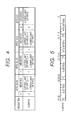
Also, a diagram illustrating the meanings of the respective fields in the dispatch unit 15 of the semiconductor device 1 according to the first embodiment is illustrated in FIG. 4. As illustrated in FIG. 4, the dispatch unit 15 recognizes a range of the hardware thread belonging to the first partition on the basis of the base thread ID of the first partition and the base thread ID of the second partition logically adjacent to the first partition. More specifically, the dispatch unit 15 recognizes a lower limit value of the hardware thread assigned to the partition PRT0 according to the base thread ID stored in the field from the 6th bit to the 0th bit, and recognizes an upper limit value of the hardware thread assigned to the partition PRT0 according to a value obtained by subtracting 1 from the base thread ID stored in the field from the 14th bit to the 8th bit.
FIG. 5 illustrates an example of the thread assignment table for defining the partitions illustrated in FIG. 1. As illustrated in FIG. 5, in order to set the partition illustrated in FIG. 1, HT0 is stored as the base thread ID in the field from the 6th bit to the 0th bit of the partition setting register VMPRTn, HT2 is stored as the base thread ID in the field from the 14th bit to the 8th bit, and a default (for example, 0) is stored in the field from the 22nd bit to the 16th bit and the field from the 30th bit to the 24th bit. With this setting, the dispatch unit 15 recognizes that the hardware threads HT0 and HT1 are assigned to the partition PRT0, and the hardware threads HT2 and HT3 are assigned to the partition PRT1.
The thread assignment table 16 is configured by the register described with reference to FIGS. 2 to 4 so that the partitions can be flexibly set without conducting a complicated calculation in the dispatch unit 15. An input of the base thread ID to the thread assignment table 16 is conducted as one processing of initializing operation conducted when the CPU 10 starts. Also, although a connection wiring between the thread assignment table 16 and the bus BUS is omitted in FIG. 1, write processing in the thread assignment table 16 is conducted by the execution unit 17 through the bus BUS. The bus BUS is disposed inside of the semiconductor device.
Subsequently, the details of the scheduler 19 will be described. The detailed block diagram of the scheduler 19 is illustrated in FIG. 6. As illustrated in FIG. 6, the scheduler has multiple thread schedulers (for example, thread schedulers 21 to 23), and a partition scheduler 24. The scheduler 19 illustrated in FIG. 6 corresponds to three partitions, and therefore has three thread schedulers. It is preferable that the number of thread schedulers is determined according to the maximum number of partitions determined in the specification.
The thread schedulers 21 to 23 are each made to correspond to any one of the multiple partitions, and output the thread select signal TSEL0 to TSEL2 including the hardware thread No. for identifying the hardware thread belonging to the corresponding partition. The thread schedulers 21 to 23 have the same circuit configuration. Therefore, in this example, the thread scheduler 21 will be described in detail, and the detailed description of the thread schedulers 22 and 23 will be omitted.
The thread scheduler 21 includes a thread schedule table 30, a first selector (for example, selector 34), a partition occupation state control register 35, and a second selector (for example, selector 38).
The thread schedule table 30 defines the thread schedule. The thread schedule table 30 includes a pointer 31, an upper limit register 32, and a first setting register (for example, thread schedule setting register 33). The pointer 31 generates a slot designation value that is incremented by one every time the thread scheduler 21 generates the thread select signal TSEL0 including the hardware thread No. The upper limit register 32 has an upper limit value of the slot designation value, and resets the pointer 31 upon arrival of the slot designation value at the upper limit value. The thread schedule setting register 33 is one of the multiple first setting registers, and the subject thread scheduler stores the hardware thread No. of the hardware thread assigned to the corresponding partition therein, and defines the thread schedule. More specifically, the thread schedule setting register 33 has multiple slots (for example, slots SLT0 to SLT3). The hardware thread Nos. are given the multiple slots SLT0 to SLT3 through the bus BUS. Also, the partition No. corresponding to the corresponding partition of the thread scheduler 21 is stored together with the hardware thread No. in the thread schedule setting register 33.
The selector 34 selects any one of the hardware thread Nos. stored in the thread schedule setting register 33 on the basis of the thread schedule. More specifically, the selector 34 has ports P0 to P3 as input terminals. The ports P0 to P3 are provided to correspond to the slots SLT0 to SLT3 of the thread schedule setting register 33. The hardware thread Nos. stored in the slots SLT0 to SLT3 are given the ports P0 to P3. Also, a slot select signal for designating the port selected from the pointer 31 is given the selector 34. That is, the selector 34 cyclically sequentially selects the hardware thread Nos. stored in the slots SLT0 to SLT3.
The partition occupation state control register 35 has a first control register (for example, register 36) and a second control register (for example, register 37). The register 36 stores a first occupied state flag indicative of the valid state therein when the first occupation control signal OCC indicates a partition corresponding to the subject thread scheduler. The register 36 makes the first occupied state flag in the invalid state when receiving the second occupation control signal OCC generated when the arithmetic instruction executed by the execution unit 17 is the first occupation cancel instruction. That is, the first occupied state flag is a setting value indicating whether one partition is made in the occupied state or in the unoccupied state. The register 37 stores the first occupation hardware thread No. for identifying the hardware thread indicated by the first occupation control signal OCC therein.
The selector 38 outputs the hardware thread No. selected by the selector 34 as the thread select signal TSEL0 when the occupied state flag is in the invalid state (for example, 0), and outputs the first occupation hardware thread No. stored in the register 37 as the thread select signal TSEL0 when the occupied state flag is in the valid state (for example, 1).
The partition scheduler 24 selects the partition that generates the arithmetic instruction in the subsequent processing cycle. The partition scheduler 24 includes a partition schedule table 40, a third selector (for example, selector 44), a fourth selector (for example, selector 45), a CPU occupied state control register 46, and a fifth selector (for example, selector 49).
The partition schedule table 40 defines the partition schedule. The partition schedule table 40 includes a pointer 41, an upper limit register 42, and a second setting register (for example, partition schedule setting register 43). The pointer 41 generates a slot designation value that is incremented by one every time the partition scheduler 24 generates the thread select signal TSEL including the hardware thread No. The upper limit register 42 has an upper limit value of the slot designation value, and resets the pointer 41 upon arrival of the slot designation value at the upper limit value. The partition schedule setting register 43 is a register that defines the thread schedule. More specifically, the partition schedule setting register 43 includes multiple slots (for example, slots SLT10 to SLT13). The partition Nos. are given slots SLT10 to SLT13 through the bus BUS.
The selector 44 outputs the partition No. corresponding to the partition that issues the arithmetic instruction in the subsequent processing cycle on the basis of the partition schedule as a partition select signal PSEL. More specifically, the selector 44 has ports P10 to P13 as input terminals. The ports P10 to P13 are provided to correspond to the slots SLT10 to SLT13 of the partition schedule setting register 43. The partition Nos. stored in the slots SLT10 to SLT13 are given the ports P10 to P13. Also, the slot select signal for designating the port selected from the pointer 41 is given the selector 44. That is, the selector 44 cyclically sequentially selects the partition Nos. stored in the slots SLT10 to SLT13.
The selector 45 selects the thread select signal output by the thread scheduler corresponding to the partition No. selected by the selector 44. More specifically, the selector 45 has ports P20 to P22 as the input terminals. The ports P20 to P22 are provided to correspond to the thread schedulers 21 to 23. The thread select signals TSEL0 to TSEL2 output by the thread schedulers 21 to 23 are given the ports P20 to P22.
The CPU occupied state control register 46 has a third control register (for example, register 47) and a fourth control register (for example, register 48). The register 47 stores the second occupied state flag which becomes in the valid state according to the third occupation control signal therein. The register 47 makes the second occupied state flag in the invalid state when receiving the fourth occupation control signal OCC generated when the arithmetic instruction executed by the execution unit 17 is the second occupation cancel instruction. That is, the second occupied state flag is a setting value indicative of whether the CPU is made in the occupied state or the unoccupied state by the specific hardware thread. The register 48 stores the first occupied hardware thread No. for identifying the hardware thread indicated by the third occupation control signal OCC therein.
The selector 49 outputs the thread select signal TSEL selected by the selector 45 when the second occupied state flag is in the invalid state (for example, 0), and outputs the second occupation hardware thread No. stored in the register 48 as the thread select signal TSEL when the second occupied state flag is in the valid state (for example, 1).
The operation of the scheduler 19 will be described. FIG. 7 illustrates the operation of the scheduler 19. The flowchart illustrated in FIG. 7 illustrates the operation of the scheduler 19 in one processing cycle. As illustrated in FIG. 7, when the processing cycle starts, the scheduler 19 first determines whether the CPU 10 is in the occupied state, or not, with reference to the second occupied state flag stored in the register 47 (Step S1). If it is determined that the CPU 10 is in the occupied state in Step S1, the second occupation hardware thread No. stored in the register 48 is selected as the thread select signal TSEL (Step S2).
On the other hand, if it is determined that the CPU 10 is in the unoccupied state in Step S1, the partition that issues the arithmetic instruction in the subsequent processing cycle is selected according to the partition schedule table (Step S3). Then, it is determined whether the selected partition is in the occupied state, or not, with reference to the first occupied state flag stored in the register 36 of the thread scheduler corresponding to the partition selected in Step S3 (Step S4).
Then, if it is determined that the partition selected in Step S4 is in the occupied state, the first occupation hardware thread No. stored in the register 37 is selected as the thread select signal TSEL (Step S5). On the other hand, if it is determined that the partition selected in Step S4 is in the unoccupied state, the hardware thread No. selected according to the partition schedule table 40 is output as the thread select signal TSEL (Step S6). Then, the processing of one processing cycle in the scheduler 19 is completed upon completion of the output of the thread select signal TSEL in Steps S2, S5, and S6.
Subsequently, the operation of the semiconductor device 1 according to the first embodiment will be described. First, the partition schedule, the thread schedule of the partition PRT0, and the thread schedule of the partition PRT1 in the operation example of the semiconductor device 1 described below are illustrated in FIG. 8. As illustrated in FIG. 8, in the operation example described below, a rate of the execution time of the partition PRT0 and the execution time of the partition PRT1 is set to 2:1. In the partition PRT0, the rate of the execution time of the hardware thread HT0 and the execution time of the hardware thread HT1 is set to 1:1. In the partition PRT1, the rate of the execution time of the hardware thread HT2 and the execution time of the hardware thread HT3 is set to 1:1. That is, in the semiconductor device 1 that operates on the basis of the schedule illustrated in FIG. 8, the rate of the execution time of the hardware threads HT0 to HT3 are roughly 33:33:17:17.
A timing chart when the semiconductor device 1 that operates on the basis of the schedule illustrated in FIG. 8 operates in a normal operation state (state in which all of the partitions and the CPU operate in the unoccupied state) is illustrated in FIG. 9. As illustrated in FIG. 9, in the normal operation, three processing cycles that the partition PRT1 is selected once after the partition PRT0 is selected twice) are repetitively conducted. Then, in a period where the partition PRT0 is selected, the hardware thread HT0 and the hardware thread HT1 are repetitively selected. In a period where the partition PRT1 is selected, the hardware thread HT2 and the hardware thread HT3 are repetitively selected. Also, in the operation example illustrated in FIG. 9, the unoccupied state of the partitions PRT0, PRT1, and the CPU is maintained in all of the period.
A diagram illustrating a software hierarchy of the semiconductor device 1 that operates on the basis of the timing chart illustrated in FIG. 9 is illustrated in FIG. 10. As illustrated in FIG. 10, the semiconductor device 1 that operates in the timing chart illustrated in FIG. 9 operates a hypervisor program on a hardware such as the CPU 10. The hypervisor program is executed by using all of the execution time of the hardware. Also, the partitions PRT0 and PRT1 are executed on the hypervisor program. The rate of the execution time of the partitions PRT0 and PRT1 is determined according to the partition schedule. Also, the hardware threads HT0 and HT1 are executed on the partition PRT0. The rate of the execution time of the hardware threads HT0 and HT1 is determined according to the thread schedule corresponding to the partition PRT0. Also, the hardware threads HT2 and HT3 are executed on the partition PRT1. The Rate of the execution time of the hardware threads HT2 and HT3 is determined according to the thread schedule corresponding to the partition PRT1.
A timing chart when the semiconductor device 1 that operates on the basis of the schedule illustrated in FIG. 8 operates in a period where the hardware thread HT1 occupies the partition PRT0 is illustrated in FIG. 11. As illustrated in FIG. 11, in the operation example, the hardware thread HT1 selected in a processing cycle t2 issues the first occupation start instruction for allowing the execution time assigned to the partition PRT0 to be occupied by the hardware thread HT1. Then, in response to the first occupation start instruction, the execution unit 17 outputs the occupation control signal OCC (for example, the first occupation control signal OCC) with the hardware thread HT1 of the partition PRT0 as the first occupation hardware thread No. In the thread scheduler 21 of the scheduler 19, the first occupied state flag of the register 36 is rewritten to the valid state according to the first occupation control signal OCC, and the hardware thread HT1 is stored in the register 37 as the first occupation hardware thread No.
Then, the partition PRT0 is occupied by the hardware thread HT1 from the processing cycle t3 upon rewriting values of the registers 36 and 37. As a result, in processing cycles t4 and t5 where the partition PRT0 is selected after the processing cycle t3, the hardware thread HT1 is selected. On the other hand, even after the processing cycle t3, in the period where the partition PRT1 is selected, the hardware threads HT2 and HT3 are repetitively selected.
Upon issuance of the first occupation cancel instruction by the hardware thread HT1 selected in a processing cycle t7, the execution unit 17 outputs the occupation control signal OCC (for example, the second occupation control signal OCC) for canceling the occupied state by the hardware thread HT1 of the partition PRT0. In the thread scheduler 21 of the scheduler 19, the first occupied state flag of the register 36 is rewritten to the invalid state according to the second occupation control signal OCC. Then, the occupied state of the partition PRT0 is canceled from a processing cycle t8 upon rewriting the value of the register 36. For that reason, after the processing cycle t8, in the period where the partition PRT0 is selected, the hardware threads HT0 and HT1 are repetitively selected.
In the operation example illustrated in FIG. 11, the unoccupied state of the partition PRT1 and the CPU is maintained. That is, the partition PRT1 can maintain the processing performance (for example, real time property) without being subject to an influence that the partition PRT1 becomes in the occupied state.
A diagram illustrating a software hierarchy of the semiconductor device in the HT1 occupied period of the timing chart illustrated in FIG. 11 is illustrated in FIG. 12. As illustrated in FIG. 12, in the HT1 occupied period illustrated in FIG. 11, the hardware thread HT0 becomes in an unscheduled state, and becomes in the occupied state where the execution time (for example, hardware resource) assigned to the partition PRT0 is dominated.
A timing chart when the semiconductor device 1 that operates on the basis of the schedule illustrated in FIG. 8 operates in a period where the hardware thread HT1 occupies the CPU 10 is illustrated in FIG. 13. As illustrated in FIG. 13, in the operation example, the hardware thread HT1 selected in the processing cycle t2 issues the second occupation start instruction for allowing the execution time of the CPU 10 to be occupied by the hardware thread HT1. Then, in response to the second occupation start instruction, the execution unit 17 outputs the occupation control signal OCC (for example, the third occupation control signal OCC) with the hardware thread HT1 occupying the CPU 10 as the second occupation hardware thread No. In the partition scheduler 24 of the scheduler 19, the second occupied state flag of the register 47 is rewritten to the valid state according to the third occupation control signal OCC, and the hardware thread HT1 is stored in the register 48 as the second occupation hardware thread No. Then, the CPU 10 is occupied by the hardware thread HT1 from the processing cycle t3 upon rewriting the values of the registers 47 and 48. For that reason, in a period from the processing cycle t3 to the issuance of the second occupation cancel instruction, only the partition PRT0 is selected. Also, in the period where the CPU is occupied, only the hardware thread HT1 is selected.
Then, upon issuance of the second occupation cancel instruction by the hardware thread HT1 selected in the processing cycle t7, the execution unit 17 outputs the occupation control signal OCC (for example, the fourth occupation control signal OCC) for canceling the occupied state by the hardware thread HT1 of the CPU 10. In the thread scheduler 21 of the scheduler 19, the second occupied state flag of the register 47 is rewritten to the invalid state according to the fourth occupation control signal OCC. Then, the occupied state of the CPU 10 is canceled from the processing cycle t8 upon rewriting the value of the register 47. For that reason, after the processing cycle t8, in the period where the partition PRT0 is selected, the hardware threads HT0 and HT1 are repetitively selected, and in the period where the partition PRT1 is selected, the hardware threads HT2 and HT3 are repetitively selected. In the operation example illustrated in FIG. 13, the unoccupied state of the partitions PRT0 and PRT1 is maintained.
A diagram illustrating a software hierarchy of the semiconductor device in the HT1 occupied period of the timing chart illustrated in FIG. 13 is illustrated in FIG. 14. As illustrated in FIG. 14, in the HT1 occupied period illustrated in FIG. 13, the hardware thread HT0 and the partition PRT1 become in the unscheduled state, and becomes in the occupied state where the hardware thread HT0 dominates the hardware resource such as the CPU.
From the above description, in the semiconductor device 1 according to the first embodiment, when the first occupation start instruction is executed in the execution unit 17, the execution unit 17 outputs the first occupation control signal OCC for designating the hardware thread that occupies one partition. Also, the scheduler 19 outputs the thread select signal TSEL for designating the hardware thread issued for the execution unit 17, and fixes the hardware thread designated by the thread select signal TSEL to the period selected by one partition according to the first occupation control signal OCC. With this operation, in the semiconductor device 1 according to the first embodiment, the state can be switched to the occupied state or the unoccupied state for each of the partitions not through the OS (operating system) or the host system such as the partition manager.
A description will be given of a problem arising when the partition division and the hardware thread control are conducted with no use of the control of the hardware thread by the scheduler 19, but, for example, through the OS or the host system such as the partition manager disclosed in Japanese Unexamined Patent Application Publication No. 2004-326749. In this case, information on which hardware thread is assigned to the partition is provided in the host system. For that reason, there arises such a problem that, in order to switch whether one partition is occupied by one hardware thread, or shared by multiple hardware threads, an independence between the respective partitions cannot be ensured without inquiring of the host system once. When the occupied state is not switched for each of the partitions, only switching of whether the execution time of the CPU 10 is shared by multiple hardware threads, or occupied can be conducted, resulting in such a problem that it is difficult to estimate the execution time for each of the hardware threads.
However, in the semiconductor device 1 according to the first embodiment, the state can be switched between the occupied state and the unoccupied state for each of the partitions not through the host system. As a result, the semiconductor device 1 can conduct the switching processing without consuming the execution time of the CPU for switching between the occupied state and the unoccupied state of the partition. Also, the semiconductor device 1 can prevent the processing capacity from be deteriorated by switching between the occupied state and the unoccupied state of the partition. Further, in the semiconductor device 1, the execution time of the CPU is not consumed for switching between the occupied state and the unoccupied state of the partition. Therefore, the execution times of the hardware thread occupying the partition and the hardware thread in which the execution is stopped can easily be estimated.
Further, in the semiconductor device 1, because the occupied state and the unoccupied state can be switched for each of the partitions, the state of the other partition can be switched while the operation of one partition is maintained. Thus, in the semiconductor device 1, because the independence of the partitions can be ensured not through the processing of the host system, the execution time for each of the partitions can be easily estimated. Also, in the semiconductor device 1, the real time property of the partition whose occupied state is not to be switched can be maintained.
Also, in the semiconductor device 1, the hardware thread assigned to the partition is set by the thread assignment table 16. The thread assignment table 16 is configured by the register in which the setting value is rewritable as illustrated in FIG. 2. For that reason, in the semiconductor device 1, the number of hardware threads to be assigned to the partitions can be changed without changing the hardware.
Also, in the partition setting register VMPRTn configuring the thread assignment table 16 in the semiconductor device 1 is stored only the lower limit value of the hardware thread which is assigned to the partition. Also, in the semiconductor device 1, the dispatch unit 15 refers to multiple fields in the partition setting register VMPRTn to recognize a range of the hardware thread assigned to one partition. In this situation, the dispatch unit 15 calculates the upper limit value of the hardware thread assigned to the first partition by subtracting 1 from the lower limit value of the hardware thread assigned to the second partition logically adjacent to the first partition. That is, the dispatch unit 15 can recognize the range of the hardware thread assigned to the partition by only a simple calculation using a simple circuit. Thus, the range of the hardware thread assigned to the partition is recognized by simple setting of the register and the simple calculation with the result that the semiconductor device 1 can reduce the circuit area of the dispatch unit 15 and the thread assignment table 16.
Also, in the semiconductor device 1, when the second occupation start instruction is executed in the execution unit 17, the execution unit 17 outputs the third occupation control signal OCC for designating the hardware thread occupying the execution time of the CPU 10. Then, the scheduler 19 fixes the hardware threads designated by the thread select signal TSEL to one according to the third occupation control signal OCC. That is, in the semiconductor device 1, if there is the hardware thread requiring the high processing capacity, the high speed processing can be realized by using all of the processing capacity of the CPU 10.
The present invention is not limited to the above embodiments, but can be appropriately changed without departing from the spirit of the invention. For example, in the above embodiments, the thread schedules and the partition schedules are set by the thread schedule table 30 and the partition schedule table 40. However, for example, the thread schedules and the partition schedules can be set by arithmetic processing of an arithmetic circuit.
Also, in FIG. 1, the dispatch unit 15 is disposed downstream of the instruction fetch unit, but the dispatch unit 15 can be disposed upstream of the instruction fetch unit. In this case, the dispatch unit 15 controls the order of the fetch processing of the instruction fetch unit.

Claims (12)

What is claimed is:
1. A semiconductor device, comprising:
a plurality of hardware threads that each issues an independent instruction flow;
an execution unit that executes an arithmetic instruction belonging to the instruction flow issued by any one of the plurality of hardware threads; and
a scheduler that includes a plurality of first setting registers provided in correspondence with a plurality of partitions and defining a correspondence relationship between the hardware threads and the partitions, and generates a thread select signal on the basis of a partition schedule defining a rate of execution times of the respective partitions, and a thread schedule defining a rate of execution times of the respective hardware threads within the execution time assigned to each of the partitions,
wherein the scheduler outputs the thread select signal designating a hardware thread indicated by a first occupation control signal as the hardware thread selected, and wherein the thread select signal is output during the execution time assigned to the partition which is indicated by the first occupation control signal, according to the first occupation control signal output by the execution unit when the arithmetic instruction executed in the execution unit is the first occupation start instruction for occupying the execution time assigned to any one of the partitions.
2. The semiconductor device according to claim 1,
wherein the scheduler includes a plurality of thread schedulers each of which corresponds to one of the plurality of partitions, and outputs the thread select signal including a hardware thread number for identifying the hardware thread belonging to the corresponding partition.
3. The semiconductor device according to claim 2,
wherein each of the plurality of thread schedulers includes one of the plurality of first setting registers, and
wherein each thread scheduler includes:
a first setting register that stores the hardware thread numbers of the hardware threads assigned to the corresponding partition therein, and defines the thread schedule;
a first selector that selects any one of the hardware thread numbers stored in the first setting register on the basis of the thread scheduler;
a first control register that stores a first occupied state flag indicative of a valid state when the first occupation control signal indicates the partition corresponding to the subject thread scheduler therein;
a second control register that stores a first occupation hardware thread number for identifying the hardware thread indicated by the first occupation control signal therein;
and
a second selector that outputs the hardware thread number selected by the first selector when the first occupied state flag is in an invalid state as the thread select signal, and outputs the occupation hardware thread number stored in the second control register when the first occupied state flag is in the valid state as the thread select signal.
4. The semiconductor device according to claim 2,
wherein each of the plurality of thread schedulers outputs a hardware thread number determined on the basis of the thread scheduler as the thread select signal according to a second occupation control signal output by the execution unit when the arithmetic instruction executed by the execution unit is a first occupation cancel instruction for canceling the occupied state of the execution time assigned to any one of the partitions.
5. The semiconductor device according to claim 2,
wherein the scheduler outputs the thread select signal including a second occupation hardware thread number corresponding to the hardware thread indicated by a third occupation control signal without depending on the thread schedule and the partition schedule according to the third occupation control signal output by the execution unit when the arithmetic instruction executed by the execution unit is a second occupation start instruction occupying all of the execution time of the execution unit.
6. The semiconductor device according to claim 5,
wherein the scheduler includes a partition scheduler that selects the partition that generates the arithmetic instruction in a subsequent processing cycle, and
wherein the partition scheduler includes:
a third selector that outputs the partition number corresponding to the partition which generates the arithmetic instruction in the subsequent processing cycle on the basis of the partition schedule;
a fourth selector that selects any one of the thread select signals output by the thread scheduler corresponding to the partition number;
a third control register that stores a second occupied state flag which becomes the valid state according to the third occupation control signal therein;
a fourth control register that stores a second occupation hardware thread number for identifying the hardware thread indicated by the third occupation control signal; and
a fifth selector that outputs the thread select signal selected by the fourth selector when the second occupied state flag is in the invalid state, and outputs the second occupation hardware thread number stored in the fourth control register when the second occupied state flag is the valid state, as the thread select signal.
7. The semiconductor device according to claim 6,
wherein the partition scheduler outputs the thread select signal determined on the basis of the thread schedule and the partition schedule, according to a fourth occupation control signal output by the execution unit when the arithmetic instruction executed in the execution unit is a second occupation cancel instruction for canceling a state in which one of the hardware threads occupies all of the execution time of the execution unit.
8. The semiconductor device according to claim 1, further comprising a thread assignment table indicative of a correspondence relationship between the partitions and the hardware threads.
9. The semiconductor device according to claim 8,
wherein, at the time of an initializing process, the semiconductor device reads a setting value indicative of a correspondence relationship between the partition and the hardware thread from a nonvolatile storage device, and stores the setting value in the thread assignment table, and writes the setting of the thread schedule in the first setting register on the basis of the thread assignment table.
10. The semiconductor device according to claim 8, further comprising: a dispatch unit that selects one of the arithmetic instructions generated by the plurality of hardware threads according to the thread select signal,
wherein the thread select signal includes a hardware thread number corresponding to the hardware thread that issues the arithmetic instruction in the subsequent processing cycle, and a partition number corresponding to the partition to which the hardware thread issuing the arithmetic instruction belongs, and
wherein the dispatch unit determines whether the combination of the partition number and the hardware thread number of the thread select signal matches a combination defined in the thread assignment table, or not, and stops the issuance of the arithmetic instruction to the execution unit if the determination result is indicative of mismatch.
11. The semiconductor device according to claim 8,
wherein the thread assignment table includes a partition setting register that defines the hardware thread belonging to the partition,
wherein the partition setting register stores a base thread identifier (ID) indicative of a lower limit value of the hardware thread belonging to the partition therein, and
wherein a partition assignment unit recognizes a scope of the hardware thread belonging to the one partition on the basis of the base thread ID of a first partition and the base thread ID of a second partition logically adjacent to the first partition.
12. A semiconductor device that assigns a plurality of hardware threads, each issuing an independent instruction flow to any one of a plurality of partitions, each logically defined, and executes the hardware threads, the semiconductor device comprising:
an execution unit that executes an arithmetic instruction belonging to the instruction flow issued by a hardware thread selected from the plurality of hardware threads according to a thread select signal; and
a scheduler that includes first setting registers provided in correspondence with the plurality of partitions and each register storing a thread schedule defining a correspondence relationship defining an assignment of execution time of the hardware thread within the corresponding partition therein, and generates the thread select signal on the basis of the thread schedule,
wherein the scheduler further includes a first control register, and outputs the thread select signal designating a specific hardware thread without depending on the thread schedule when the first control register is set to a setting value indicating that one partition is in an occupied state.
US13/859,200 2012-05-01 2013-04-09 Thread scheduling in a system with multiple virtual machines Active 2035-06-21 US9465610B2 (en)

Applications Claiming Priority (2)

Application Number Priority Date Filing Date Title
JP2012-104577 2012-05-01
JP2012104577A JP5894496B2 (en) 2012-05-01 2012-05-01 Semiconductor device

Publications (2)

Publication Number Publication Date
US20130297916A1 US20130297916A1 (en) 2013-11-07
US9465610B2 true US9465610B2 (en) 2016-10-11

Family

ID=48190708

Family Applications (1)

Application Number Title Priority Date Filing Date
US13/859,200 Active 2035-06-21 US9465610B2 (en) 2012-05-01 2013-04-09 Thread scheduling in a system with multiple virtual machines

Country Status (5)

Country Link
US (1) US9465610B2 (en)
EP (1) EP2660714B1 (en)
JP (1) JP5894496B2 (en)
CN (1) CN103383651B (en)
TW (1) TWI566174B (en)

Families Citing this family (16)

* Cited by examiner, † Cited by third party
Publication number Priority date Publication date Assignee Title
CN106030519A (en) * 2014-03-27 2016-10-12 英特尔公司 Processor logic and method for dispatching instructions from multiple strands
CN105302078B (en) * 2014-06-04 2018-11-16 中芯国际集成电路制造(上海)有限公司 The control system and method for boiler tube board operation in a kind of semiconductor fabrication process
WO2015186088A1 (en) * 2014-06-06 2015-12-10 International Business Machines Corporation Selecting a host for a virtual machine using a hardware multithreading parameter
US9304805B2 (en) 2014-06-06 2016-04-05 Interinational Business Machines Corporation Provisioning virtual CPUs using a hardware multithreading parameter in hosts with split core processors
US9400672B2 (en) 2014-06-06 2016-07-26 International Business Machines Corporation Placement of virtual CPUS using a hardware multithreading parameter
JP6628742B2 (en) * 2014-06-06 2020-01-15 インターナショナル・ビジネス・マシーンズ・コーポレーションInternational Business Machines Corporation Method and apparatus for selecting a host for a virtual machine using hardware multithreading parameters
US9384027B2 (en) 2014-06-06 2016-07-05 International Business Machines Corporation Selecting a host for a virtual machine using a hardware multithreading parameter
US10558463B2 (en) * 2016-06-03 2020-02-11 Synopsys, Inc. Communication between threads of multi-thread processor
US10628320B2 (en) 2016-06-03 2020-04-21 Synopsys, Inc. Modulization of cache structure utilizing independent tag array and data array in microprocessor
US10318302B2 (en) 2016-06-03 2019-06-11 Synopsys, Inc. Thread switching in microprocessor without full save and restore of register file
US10613859B2 (en) 2016-08-18 2020-04-07 Synopsys, Inc. Triple-pass execution using a retire queue having a functional unit to independently execute long latency instructions and dependent instructions
US10552158B2 (en) 2016-08-18 2020-02-04 Synopsys, Inc. Reorder buffer scoreboard having multiple valid bits to indicate a location of data
CN109032665B (en) * 2017-06-09 2021-01-26 龙芯中科技术股份有限公司 Method and device for processing instruction output in microprocessor
US10606641B2 (en) 2017-10-20 2020-03-31 Graphcore Limited Scheduling tasks in a multi-threaded processor
GB201717303D0 (en) * 2017-10-20 2017-12-06 Graphcore Ltd Scheduling tasks in a multi-threaded processor
KR20190138083A (en) * 2018-06-04 2019-12-12 에스케이하이닉스 주식회사 Semiconductor device

Citations (35)

* Cited by examiner, † Cited by third party
Publication number Priority date Publication date Assignee Title
US5987557A (en) * 1997-06-19 1999-11-16 Sun Microsystems, Inc. Method and apparatus for implementing hardware protection domains in a system with no memory management unit (MMU)
US20020129172A1 (en) * 2001-03-08 2002-09-12 International Business Machines Corporation Inter-partition message passing method, system and program product for a shared I/O driver
US20020129274A1 (en) * 2001-03-08 2002-09-12 International Business Machines Corporation Inter-partition message passing method, system and program product for a security server in a partitioned processing environment
US20040215945A1 (en) 2003-04-24 2004-10-28 International Business Machines Corporation Method for changing a thread priority in a simultaneous multithread processor
US20040215939A1 (en) 2003-04-24 2004-10-28 International Business Machines Corporation Dynamic switching of multithreaded processor between single threaded and simultaneous multithreaded modes
EP1555610A1 (en) 2003-12-18 2005-07-20 Nvidia Corporation Out of order instruction dispatch in a multithreaded microprocessor
US6985951B2 (en) * 2001-03-08 2006-01-10 International Business Machines Corporation Inter-partition message passing method, system and program product for managing workload in a partitioned processing environment
US20060095901A1 (en) * 2004-10-07 2006-05-04 Brokenshire Daniel A System and method for partitioning processor resources based on memory usage
US7089558B2 (en) * 2001-03-08 2006-08-08 International Business Machines Corporation Inter-partition message passing method, system and program product for throughput measurement in a partitioned processing environment
US20060206881A1 (en) * 2005-03-14 2006-09-14 Dan Dodge Process scheduler employing adaptive partitioning of critical process threads
US20070101013A1 (en) * 2005-09-26 2007-05-03 John Howson Scalable multi-threaded media processing architecture
US20070143582A1 (en) 2005-12-16 2007-06-21 Nvidia Corporation System and method for grouping execution threads
US20070226739A1 (en) * 2005-03-14 2007-09-27 Dan Dodge Process scheduler employing adaptive partitioning of process threads
US20080022283A1 (en) * 2006-07-19 2008-01-24 International Business Machines Corporation Quality of service scheduling for simultaneous multi-threaded processors
US20080196031A1 (en) * 2005-03-14 2008-08-14 Attilla Danko Adaptive partitioning scheduler for multiprocessing system
US20090007100A1 (en) * 2007-06-28 2009-01-01 Microsoft Corporation Suspending a Running Operating System to Enable Security Scanning
US20090037908A1 (en) * 2007-08-02 2009-02-05 International Business Machines Corporation Partition adjunct with non-native device driver for facilitating access to a physical input/output device
US20090037941A1 (en) * 2007-08-02 2009-02-05 International Business Machines Corporation Multiple partition adjunct instances interfacing multiple logical partitions to a self-virtualizing input/output device
US20090037682A1 (en) * 2007-08-02 2009-02-05 International Business Machines Corporation Hypervisor-enforced isolation of entities within a single logical partition's virtual address space
US20090210879A1 (en) * 2004-11-11 2009-08-20 Robert Kaiser Method for distributing computing time in a computer system
US20100115243A1 (en) * 2003-08-28 2010-05-06 Mips Technologies, Inc. Apparatus, Method and Instruction for Initiation of Concurrent Instruction Streams in a Multithreading Microprocessor
US20110099551A1 (en) * 2009-10-26 2011-04-28 Microsoft Corporation Opportunistically Scheduling and Adjusting Time Slices
US20110276784A1 (en) 2010-05-10 2011-11-10 Telefonaktiebolaget L M Ericsson (Publ) Hierarchical multithreaded processing
US8365179B2 (en) * 2008-09-30 2013-01-29 Renesas Electronics Corporation Multi-thread processor and its hardware thread scheduling method
US8407387B2 (en) * 2008-09-30 2013-03-26 Renesas Electronics Corporation Multi-thread processor and the multi-thread processor's interrupt processing method having interrupt processing that is processed by an associated hardware thread
US8539203B2 (en) * 2008-09-30 2013-09-17 Renesas Electronics Corporation Multi-thread processor selecting threads on different schedule pattern for interrupt processing and normal operation
US20130263129A1 (en) * 2012-03-30 2013-10-03 Renesas Electronics Corporation Semiconductor device
US20130297901A1 (en) * 2012-05-01 2013-11-07 Renesas Electronics Corporation Memory protection circuit, processing unit, and memory protection method
US8607030B2 (en) * 2008-09-30 2013-12-10 Renesas Electronics Corporation Scheduling threads instructions in variably selected or predetermined order periods of requested time ratio
US20140109098A1 (en) * 2012-10-17 2014-04-17 Renesas Electronics Corporation Multi-thread processor
US8766996B2 (en) * 2006-06-21 2014-07-01 Qualcomm Incorporated Unified virtual addressed register file
US20140281442A1 (en) * 2013-03-15 2014-09-18 International Business Machines Corporation System management and instruction counting
US20150178131A1 (en) * 2013-12-19 2015-06-25 International Business Machines Corporation Honoring hardware entitlement of a hardware thread
US9081621B2 (en) * 2009-11-25 2015-07-14 Microsoft Technology Licensing, Llc Efficient input/output-aware multi-processor virtual machine scheduling
US9158692B2 (en) * 2008-08-12 2015-10-13 International Business Machines Corporation Cache injection directing technique

Family Cites Families (2)

* Cited by examiner, † Cited by third party
Publication number Priority date Publication date Assignee Title
FR2957433B1 (en) * 2010-03-11 2016-01-15 Bull Sas METHOD FOR CONFIGURING A COMPUTER SYSTEM, CORRESPONDING COMPUTER PROGRAM AND COMPUTER SYSTEM
US8954986B2 (en) * 2010-12-17 2015-02-10 Intel Corporation Systems and methods for data-parallel processing

Patent Citations (78)

* Cited by examiner, † Cited by third party
Publication number Priority date Publication date Assignee Title
US5987557A (en) * 1997-06-19 1999-11-16 Sun Microsystems, Inc. Method and apparatus for implementing hardware protection domains in a system with no memory management unit (MMU)
US7089558B2 (en) * 2001-03-08 2006-08-08 International Business Machines Corporation Inter-partition message passing method, system and program product for throughput measurement in a partitioned processing environment
US20020129172A1 (en) * 2001-03-08 2002-09-12 International Business Machines Corporation Inter-partition message passing method, system and program product for a shared I/O driver
US6985951B2 (en) * 2001-03-08 2006-01-10 International Business Machines Corporation Inter-partition message passing method, system and program product for managing workload in a partitioned processing environment
US20020129274A1 (en) * 2001-03-08 2002-09-12 International Business Machines Corporation Inter-partition message passing method, system and program product for a security server in a partitioned processing environment
US20040215945A1 (en) 2003-04-24 2004-10-28 International Business Machines Corporation Method for changing a thread priority in a simultaneous multithread processor
US20090144737A1 (en) 2003-04-24 2009-06-04 International Business Machines Corporation Dynamic switching of multithreaded processor between single threaded and simultaneous multithreaded modes
JP2004326749A (en) 2003-04-24 2004-11-18 Internatl Business Mach Corp <Ibm> Device and method for dynamically switching multithread processor between single thread mode and simultaneous multithread mode
US7496915B2 (en) 2003-04-24 2009-02-24 International Business Machines Corporation Dynamic switching of multithreaded processor between single threaded and simultaneous multithreaded modes
US20040215939A1 (en) 2003-04-24 2004-10-28 International Business Machines Corporation Dynamic switching of multithreaded processor between single threaded and simultaneous multithreaded modes
US8145884B2 (en) * 2003-08-28 2012-03-27 Mips Technologies, Inc. Apparatus, method and instruction for initiation of concurrent instruction streams in a multithreading microprocessor
US20100115243A1 (en) * 2003-08-28 2010-05-06 Mips Technologies, Inc. Apparatus, Method and Instruction for Initiation of Concurrent Instruction Streams in a Multithreading Microprocessor
EP1555610A1 (en) 2003-12-18 2005-07-20 Nvidia Corporation Out of order instruction dispatch in a multithreaded microprocessor
US20060095901A1 (en) * 2004-10-07 2006-05-04 Brokenshire Daniel A System and method for partitioning processor resources based on memory usage
US8032871B2 (en) * 2004-10-07 2011-10-04 International Business Machines Corporation Partitioning processor resources based on memory usage
US20090138689A1 (en) * 2004-10-07 2009-05-28 International Business Machines Corporation Partitioning Processor Resources Based on Memory Usage
US7506325B2 (en) * 2004-10-07 2009-03-17 International Business Machines Corporation Partitioning processor resources based on memory usage
US8695004B2 (en) * 2004-11-11 2014-04-08 Sysgo Ag Method for distributing computing time in a computer system
US20090210879A1 (en) * 2004-11-11 2009-08-20 Robert Kaiser Method for distributing computing time in a computer system
US8544013B2 (en) * 2005-03-14 2013-09-24 Qnx Software Systems Limited Process scheduler having multiple adaptive partitions associated with process threads accessing mutexes and the like
US7840966B2 (en) * 2005-03-14 2010-11-23 Qnx Software Systems Gmbh & Co. Kg Process scheduler employing adaptive partitioning of critical process threads
US8595733B2 (en) * 2005-03-14 2013-11-26 Qnx Software Systems Limited Process scheduler employing ordering function to schedule threads running in multiple adaptive partitions
US8631409B2 (en) * 2005-03-14 2014-01-14 Qnx Software Systems Limited Adaptive partitioning scheduler for multiprocessing system
US20070061788A1 (en) * 2005-03-14 2007-03-15 Dan Dodge Process scheduler employing ordering function to schedule threads running in multiple adaptive partitions
US20130247066A1 (en) * 2005-03-14 2013-09-19 Qnx Software Systems Limited Process Scheduler Employing Adaptive Partitioning of Process Threads
US8434086B2 (en) * 2005-03-14 2013-04-30 Qnx Software Systems Limited Process scheduler employing adaptive partitioning of process threads
US20060206881A1 (en) * 2005-03-14 2006-09-14 Dan Dodge Process scheduler employing adaptive partitioning of critical process threads
US20080196031A1 (en) * 2005-03-14 2008-08-14 Attilla Danko Adaptive partitioning scheduler for multiprocessing system
US20070061809A1 (en) * 2005-03-14 2007-03-15 Dan Dodge Process scheduler having multiple adaptive partitions associated with process threads accessing mutexes and the like
US20080235701A1 (en) * 2005-03-14 2008-09-25 Attilla Danko Adaptive partitioning scheduler for multiprocessing system
US20070226739A1 (en) * 2005-03-14 2007-09-27 Dan Dodge Process scheduler employing adaptive partitioning of process threads
US20110107342A1 (en) * 2005-03-14 2011-05-05 Qnx Software Systems Gmbh & Co. Kg Process scheduler employing ordering function to schedule threads running in multiple adaptive partitions
US8245230B2 (en) * 2005-03-14 2012-08-14 Qnx Software Systems Limited Adaptive partitioning scheduler for multiprocessing system
US7870554B2 (en) * 2005-03-14 2011-01-11 Qnx Software Systems Gmbh & Co. Kg Process scheduler employing ordering function to schedule threads running in multiple adaptive partitions
US8046761B2 (en) * 2005-09-26 2011-10-25 Imagination Technologies Limited Scalable multi-threaded media processing architecture
US20070101013A1 (en) * 2005-09-26 2007-05-03 John Howson Scalable multi-threaded media processing architecture
US20070143582A1 (en) 2005-12-16 2007-06-21 Nvidia Corporation System and method for grouping execution threads
US8766996B2 (en) * 2006-06-21 2014-07-01 Qualcomm Incorporated Unified virtual addressed register file
US20080229321A1 (en) * 2006-07-19 2008-09-18 International Business Machines Corporation Quality of service scheduling for simultaneous multi-threaded processors
US8869153B2 (en) * 2006-07-19 2014-10-21 International Business Machines Corporation Quality of service scheduling for simultaneous multi-threaded processors
US20080022283A1 (en) * 2006-07-19 2008-01-24 International Business Machines Corporation Quality of service scheduling for simultaneous multi-threaded processors
US20090007100A1 (en) * 2007-06-28 2009-01-01 Microsoft Corporation Suspending a Running Operating System to Enable Security Scanning
US20090037941A1 (en) * 2007-08-02 2009-02-05 International Business Machines Corporation Multiple partition adjunct instances interfacing multiple logical partitions to a self-virtualizing input/output device
US8010763B2 (en) * 2007-08-02 2011-08-30 International Business Machines Corporation Hypervisor-enforced isolation of entities within a single logical partition's virtual address space
US8219988B2 (en) * 2007-08-02 2012-07-10 International Business Machines Corporation Partition adjunct for data processing system
US20090037908A1 (en) * 2007-08-02 2009-02-05 International Business Machines Corporation Partition adjunct with non-native device driver for facilitating access to a physical input/output device
US20120210044A1 (en) * 2007-08-02 2012-08-16 International Business Machines Corporation Partition adjunct for data processing system
US8176487B2 (en) * 2007-08-02 2012-05-08 International Business Machines Corporation Client partition scheduling and prioritization of service partition work
US8219989B2 (en) * 2007-08-02 2012-07-10 International Business Machines Corporation Partition adjunct with non-native device driver for facilitating access to a physical input/output device
US20090037906A1 (en) * 2007-08-02 2009-02-05 International Business Machines Corporation Partition adjunct for data processing system
US8645974B2 (en) * 2007-08-02 2014-02-04 International Business Machines Corporation Multiple partition adjunct instances interfacing multiple logical partitions to a self-virtualizing input/output device
US20120117353A1 (en) * 2007-08-02 2012-05-10 International Business Machines Corporation Client partition scheduling and prioritization of service partition work
US8495632B2 (en) * 2007-08-02 2013-07-23 International Business Machines Corporation Partition adjunct for data processing system
US20090037907A1 (en) * 2007-08-02 2009-02-05 International Business Machines Corporation Client partition scheduling and prioritization of service partition work
US20090037682A1 (en) * 2007-08-02 2009-02-05 International Business Machines Corporation Hypervisor-enforced isolation of entities within a single logical partition's virtual address space
US9158692B2 (en) * 2008-08-12 2015-10-13 International Business Machines Corporation Cache injection directing technique
US8407387B2 (en) * 2008-09-30 2013-03-26 Renesas Electronics Corporation Multi-thread processor and the multi-thread processor's interrupt processing method having interrupt processing that is processed by an associated hardware thread
US8365179B2 (en) * 2008-09-30 2013-01-29 Renesas Electronics Corporation Multi-thread processor and its hardware thread scheduling method
US8607030B2 (en) * 2008-09-30 2013-12-10 Renesas Electronics Corporation Scheduling threads instructions in variably selected or predetermined order periods of requested time ratio
US20130332717A1 (en) * 2008-09-30 2013-12-12 Renesas Electronics Corporation Multi-thread processor
US9098336B2 (en) * 2008-09-30 2015-08-04 Renesas Electronics Corporation Multi-thread processor and its hardware thread scheduling method
US8539203B2 (en) * 2008-09-30 2013-09-17 Renesas Electronics Corporation Multi-thread processor selecting threads on different schedule pattern for interrupt processing and normal operation
US20140089938A1 (en) * 2008-09-30 2014-03-27 Renesas Electronics Corporation Multi-thread processor and its hardware thread scheduling method
US20130205058A1 (en) * 2008-09-30 2013-08-08 Renesas Electronics Corporation Multi-thread processor and its interrupt processing method
US9086922B2 (en) * 2009-10-26 2015-07-21 Microsoft Technology Licensing, Llc Opportunistically scheduling and adjusting time slices
US20110099551A1 (en) * 2009-10-26 2011-04-28 Microsoft Corporation Opportunistically Scheduling and Adjusting Time Slices
US20150324231A1 (en) * 2009-10-26 2015-11-12 Microsoft Technology Licensing, Llc Opportunistically scheduling and adjusting time slices
US9081621B2 (en) * 2009-11-25 2015-07-14 Microsoft Technology Licensing, Llc Efficient input/output-aware multi-processor virtual machine scheduling
US20150317179A1 (en) * 2009-11-25 2015-11-05 Microsoft Technology Licensing, Llc Efficient input/output-aware multi-processor virtual machine scheduling
US20110276784A1 (en) 2010-05-10 2011-11-10 Telefonaktiebolaget L M Ericsson (Publ) Hierarchical multithreaded processing
US20130263129A1 (en) * 2012-03-30 2013-10-03 Renesas Electronics Corporation Semiconductor device
US9286091B2 (en) * 2012-03-30 2016-03-15 Renesas Electronics Corporation Semiconductor device improving performance of virtual machines
US20130297901A1 (en) * 2012-05-01 2013-11-07 Renesas Electronics Corporation Memory protection circuit, processing unit, and memory protection method
US20140109098A1 (en) * 2012-10-17 2014-04-17 Renesas Electronics Corporation Multi-thread processor
US20140282607A1 (en) * 2013-03-15 2014-09-18 International Business Machines Corporation System management and instruction counting
US20140281442A1 (en) * 2013-03-15 2014-09-18 International Business Machines Corporation System management and instruction counting
US20150178131A1 (en) * 2013-12-19 2015-06-25 International Business Machines Corporation Honoring hardware entitlement of a hardware thread
US20150178088A1 (en) * 2013-12-19 2015-06-25 International Business Machines Corporation Honoring hardware entitlement of a hardware thread

Non-Patent Citations (3)

* Cited by examiner, † Cited by third party
Title
'Denali: Lightweight Virtual Machines for Distributed and Networked Applications' by Andrew Whitaker et al., 2002. *
European Search Report dated May 16, 2014, EP 13163470.
'Hardware Threads vs Software Threads' by Mohd Rafi, Oct. 25, 2012. *

Also Published As

Publication number Publication date
TWI566174B (en) 2017-01-11
EP2660714B1 (en) 2018-06-06
CN103383651A (en) 2013-11-06
US20130297916A1 (en) 2013-11-07
JP2013232150A (en) 2013-11-14
CN103383651B (en) 2018-04-03
JP5894496B2 (en) 2016-03-30
EP2660714A3 (en) 2014-06-18
TW201411484A (en) 2014-03-16
EP2660714A2 (en) 2013-11-06

Similar Documents

Publication Publication Date Title
US9465610B2 (en) Thread scheduling in a system with multiple virtual machines
US9442870B2 (en) Interrupt priority management using partition-based priority blocking processor registers
JP6294586B2 (en) Execution management system combining instruction threads and management method
US8695002B2 (en) Multi-threaded processors and multi-processor systems comprising shared resources
US9465750B2 (en) Memory protection circuit, method and processing unit utilizing memory access information register to selectively allow access to memory areas by virtual machines
JP5295228B2 (en) System including a plurality of processors and method of operating the same
US9436464B2 (en) Instruction-issuance controlling device and instruction-issuance controlling method
US10545892B2 (en) Multi-thread processor and its interrupt processing method
JP2013542499A (en) Data processing device debugging
WO2008145653A1 (en) Scheduling threads in a processor
US11893390B2 (en) Method of debugging a processor that executes vertices of an application, each vertex being assigned to a programming thread of the processor
JP2003058368A (en) Handling of coprocessor instruction in data processor
US20100095305A1 (en) Simultaneous multithread instruction completion controller
US11645081B2 (en) Handling exceptions in a multi-tile processing arrangement
US20080010426A1 (en) Processor system and processing method for operating system program in processor system
US11449338B2 (en) Handling exceptions in a multi-tile processing arrangement
US8910181B2 (en) Divided central data processing
JP2016531363A (en) Handling time-consuming instructions
US8973006B2 (en) Circuit arrangement for execution planning in a data processing system
US6711655B1 (en) Finding available memory space by finding its associated memory transfer controller
JPH0744401A (en) Logic integrated circuit and its data processing system
JP2008225710A (en) Computer system and process-switching method used in the system
CN115640051A (en) Multi-thread processor
GB2583574A (en) Handling exceptions in a multi-tile processing arrangement
JP2011008617A (en) Multithread execution device, method of generating object program, and program

Legal Events

Date Code Title Description
AS Assignment

Owner name: RENESAS ELECTRONICS CORPORATION, JAPAN

Free format text: ASSIGNMENT OF ASSIGNORS INTEREST;ASSIGNORS:SUZUKI, HITOSHI;ADACHI, KOJI;REEL/FRAME:030254/0750

Effective date: 20130321

STCF Information on status: patent grant

Free format text: PATENTED CASE

AS Assignment

Owner name: RENESAS ELECTRONICS CORPORATION, JAPAN

Free format text: CHANGE OF ADDRESS;ASSIGNOR:RENESAS ELECTRONICS CORPORATION;REEL/FRAME:044928/0001

Effective date: 20150806

MAFP Maintenance fee payment

Free format text: PAYMENT OF MAINTENANCE FEE, 4TH YEAR, LARGE ENTITY (ORIGINAL EVENT CODE: M1551); ENTITY STATUS OF PATENT OWNER: LARGE ENTITY

Year of fee payment: 4

MAFP Maintenance fee payment

Free format text: PAYMENT OF MAINTENANCE FEE, 8TH YEAR, LARGE ENTITY (ORIGINAL EVENT CODE: M1552); ENTITY STATUS OF PATENT OWNER: LARGE ENTITY

Year of fee payment: 8