US9408649B2 - Radiolucent screw with radiopaque marker - Google Patents
Radiolucent screw with radiopaque marker Download PDFInfo
- Publication number
- US9408649B2 US9408649B2 US12/208,986 US20898608A US9408649B2 US 9408649 B2 US9408649 B2 US 9408649B2 US 20898608 A US20898608 A US 20898608A US 9408649 B2 US9408649 B2 US 9408649B2
- Authority
- US
- United States
- Prior art keywords
- shaft
- core
- recited
- head
- bone screw
- Prior art date
- Legal status (The legal status is an assumption and is not a legal conclusion. Google has not performed a legal analysis and makes no representation as to the accuracy of the status listed.)
- Active, expires
Links
- 239000003550 marker Substances 0.000 title description 3
- 210000000988 bone and bone Anatomy 0.000 claims abstract description 89
- 239000000463 material Substances 0.000 claims abstract description 36
- 239000000835 fiber Substances 0.000 claims description 38
- 238000000034 method Methods 0.000 claims description 38
- 239000000853 adhesive Substances 0.000 claims description 25
- 230000001070 adhesive effect Effects 0.000 claims description 25
- 229910052751 metal Inorganic materials 0.000 claims description 10
- 239000002184 metal Substances 0.000 claims description 10
- 238000004519 manufacturing process Methods 0.000 claims description 9
- 239000011159 matrix material Substances 0.000 claims description 8
- 239000004696 Poly ether ether ketone Substances 0.000 claims description 6
- 229920002530 polyetherether ketone Polymers 0.000 claims description 6
- 238000004804 winding Methods 0.000 claims description 6
- 238000005520 cutting process Methods 0.000 claims description 5
- 230000000087 stabilizing effect Effects 0.000 description 19
- 229920000647 polyepoxide Polymers 0.000 description 8
- RTAQQCXQSZGOHL-UHFFFAOYSA-N Titanium Chemical compound [Ti] RTAQQCXQSZGOHL-UHFFFAOYSA-N 0.000 description 7
- 239000010936 titanium Substances 0.000 description 7
- 229910052719 titanium Inorganic materials 0.000 description 7
- 239000004593 Epoxy Substances 0.000 description 6
- 229910045601 alloy Inorganic materials 0.000 description 6
- 239000000956 alloy Substances 0.000 description 6
- 238000002513 implantation Methods 0.000 description 6
- 239000010935 stainless steel Substances 0.000 description 6
- 229910001220 stainless steel Inorganic materials 0.000 description 6
- 125000003700 epoxy group Chemical group 0.000 description 4
- 239000003822 epoxy resin Substances 0.000 description 4
- 239000004033 plastic Substances 0.000 description 4
- 229920003023 plastic Polymers 0.000 description 4
- WFKWXMTUELFFGS-UHFFFAOYSA-N tungsten Chemical compound [W] WFKWXMTUELFFGS-UHFFFAOYSA-N 0.000 description 4
- 229910052721 tungsten Inorganic materials 0.000 description 4
- 239000010937 tungsten Substances 0.000 description 4
- 238000009730 filament winding Methods 0.000 description 3
- 150000002739 metals Chemical class 0.000 description 3
- 238000010079 rubber tapping Methods 0.000 description 3
- 229920000049 Carbon (fiber) Polymers 0.000 description 2
- 230000008901 benefit Effects 0.000 description 2
- 239000004917 carbon fiber Substances 0.000 description 2
- 230000000295 complement effect Effects 0.000 description 2
- 230000000694 effects Effects 0.000 description 2
- VNWKTOKETHGBQD-UHFFFAOYSA-N methane Chemical compound C VNWKTOKETHGBQD-UHFFFAOYSA-N 0.000 description 2
- 229920005989 resin Polymers 0.000 description 2
- 239000011347 resin Substances 0.000 description 2
- 238000003466 welding Methods 0.000 description 2
- 229920000271 Kevlar® Polymers 0.000 description 1
- 239000004952 Polyamide Substances 0.000 description 1
- 239000004698 Polyethylene Substances 0.000 description 1
- 239000004642 Polyimide Substances 0.000 description 1
- 206010058907 Spinal deformity Diseases 0.000 description 1
- 238000004873 anchoring Methods 0.000 description 1
- 239000000560 biocompatible material Substances 0.000 description 1
- 238000003486 chemical etching Methods 0.000 description 1
- 238000000748 compression moulding Methods 0.000 description 1
- 238000002591 computed tomography Methods 0.000 description 1
- 238000007796 conventional method Methods 0.000 description 1
- 238000005516 engineering process Methods 0.000 description 1
- 239000011152 fibreglass Substances 0.000 description 1
- 238000003384 imaging method Methods 0.000 description 1
- 239000007943 implant Substances 0.000 description 1
- 230000003993 interaction Effects 0.000 description 1
- 230000001788 irregular Effects 0.000 description 1
- 239000004761 kevlar Substances 0.000 description 1
- 239000000203 mixture Substances 0.000 description 1
- 238000000465 moulding Methods 0.000 description 1
- 230000035515 penetration Effects 0.000 description 1
- 239000011295 pitch Substances 0.000 description 1
- 229920002647 polyamide Polymers 0.000 description 1
- -1 polyethylene Polymers 0.000 description 1
- 229920000573 polyethylene Polymers 0.000 description 1
- 229920001721 polyimide Polymers 0.000 description 1
- 229920002635 polyurethane Polymers 0.000 description 1
- 239000004814 polyurethane Substances 0.000 description 1
- 238000007788 roughening Methods 0.000 description 1
- 238000005488 sandblasting Methods 0.000 description 1
- 206010039722 scoliosis Diseases 0.000 description 1
- 238000000926 separation method Methods 0.000 description 1
Images


Classifications
-
- A—HUMAN NECESSITIES
- A61—MEDICAL OR VETERINARY SCIENCE; HYGIENE
- A61B—DIAGNOSIS; SURGERY; IDENTIFICATION
- A61B17/00—Surgical instruments, devices or methods, e.g. tourniquets
- A61B17/56—Surgical instruments or methods for treatment of bones or joints; Devices specially adapted therefor
- A61B17/58—Surgical instruments or methods for treatment of bones or joints; Devices specially adapted therefor for osteosynthesis, e.g. bone plates, screws, setting implements or the like
- A61B17/68—Internal fixation devices, including fasteners and spinal fixators, even if a part thereof projects from the skin
- A61B17/84—Fasteners therefor or fasteners being internal fixation devices
- A61B17/86—Pins or screws or threaded wires; nuts therefor
- A61B17/8685—Pins or screws or threaded wires; nuts therefor comprising multiple separate parts
-
- A—HUMAN NECESSITIES
- A61—MEDICAL OR VETERINARY SCIENCE; HYGIENE
- A61B—DIAGNOSIS; SURGERY; IDENTIFICATION
- A61B17/00—Surgical instruments, devices or methods, e.g. tourniquets
- A61B17/56—Surgical instruments or methods for treatment of bones or joints; Devices specially adapted therefor
- A61B17/58—Surgical instruments or methods for treatment of bones or joints; Devices specially adapted therefor for osteosynthesis, e.g. bone plates, screws, setting implements or the like
- A61B17/68—Internal fixation devices, including fasteners and spinal fixators, even if a part thereof projects from the skin
- A61B17/70—Spinal positioners or stabilisers ; Bone stabilisers comprising fluid filler in an implant
- A61B17/7001—Screws or hooks combined with longitudinal elements which do not contact vertebrae
- A61B17/7032—Screws or hooks with U-shaped head or back through which longitudinal rods pass
-
- A—HUMAN NECESSITIES
- A61—MEDICAL OR VETERINARY SCIENCE; HYGIENE
- A61B—DIAGNOSIS; SURGERY; IDENTIFICATION
- A61B17/00—Surgical instruments, devices or methods, e.g. tourniquets
- A61B17/56—Surgical instruments or methods for treatment of bones or joints; Devices specially adapted therefor
- A61B17/58—Surgical instruments or methods for treatment of bones or joints; Devices specially adapted therefor for osteosynthesis, e.g. bone plates, screws, setting implements or the like
- A61B17/68—Internal fixation devices, including fasteners and spinal fixators, even if a part thereof projects from the skin
- A61B17/70—Spinal positioners or stabilisers ; Bone stabilisers comprising fluid filler in an implant
- A61B17/7001—Screws or hooks combined with longitudinal elements which do not contact vertebrae
- A61B17/7035—Screws or hooks, wherein a rod-clamping part and a bone-anchoring part can pivot relative to each other
- A61B17/7037—Screws or hooks, wherein a rod-clamping part and a bone-anchoring part can pivot relative to each other wherein pivoting is blocked when the rod is clamped
-
- A—HUMAN NECESSITIES
- A61—MEDICAL OR VETERINARY SCIENCE; HYGIENE
- A61B—DIAGNOSIS; SURGERY; IDENTIFICATION
- A61B17/00—Surgical instruments, devices or methods, e.g. tourniquets
- A61B17/56—Surgical instruments or methods for treatment of bones or joints; Devices specially adapted therefor
- A61B17/58—Surgical instruments or methods for treatment of bones or joints; Devices specially adapted therefor for osteosynthesis, e.g. bone plates, screws, setting implements or the like
- A61B17/68—Internal fixation devices, including fasteners and spinal fixators, even if a part thereof projects from the skin
- A61B17/84—Fasteners therefor or fasteners being internal fixation devices
- A61B17/86—Pins or screws or threaded wires; nuts therefor
- A61B17/866—Material or manufacture
-
- A—HUMAN NECESSITIES
- A61—MEDICAL OR VETERINARY SCIENCE; HYGIENE
- A61B—DIAGNOSIS; SURGERY; IDENTIFICATION
- A61B17/00—Surgical instruments, devices or methods, e.g. tourniquets
- A61B17/56—Surgical instruments or methods for treatment of bones or joints; Devices specially adapted therefor
- A61B17/58—Surgical instruments or methods for treatment of bones or joints; Devices specially adapted therefor for osteosynthesis, e.g. bone plates, screws, setting implements or the like
- A61B17/68—Internal fixation devices, including fasteners and spinal fixators, even if a part thereof projects from the skin
- A61B17/84—Fasteners therefor or fasteners being internal fixation devices
- A61B17/86—Pins or screws or threaded wires; nuts therefor
- A61B17/8625—Shanks, i.e. parts contacting bone tissue
-
- A—HUMAN NECESSITIES
- A61—MEDICAL OR VETERINARY SCIENCE; HYGIENE
- A61B—DIAGNOSIS; SURGERY; IDENTIFICATION
- A61B17/00—Surgical instruments, devices or methods, e.g. tourniquets
- A61B17/56—Surgical instruments or methods for treatment of bones or joints; Devices specially adapted therefor
- A61B17/58—Surgical instruments or methods for treatment of bones or joints; Devices specially adapted therefor for osteosynthesis, e.g. bone plates, screws, setting implements or the like
- A61B17/68—Internal fixation devices, including fasteners and spinal fixators, even if a part thereof projects from the skin
- A61B17/84—Fasteners therefor or fasteners being internal fixation devices
- A61B17/86—Pins or screws or threaded wires; nuts therefor
- A61B17/864—Pins or screws or threaded wires; nuts therefor hollow, e.g. with socket or cannulated
-
- A61B19/54—
-
- A—HUMAN NECESSITIES
- A61—MEDICAL OR VETERINARY SCIENCE; HYGIENE
- A61B—DIAGNOSIS; SURGERY; IDENTIFICATION
- A61B17/00—Surgical instruments, devices or methods, e.g. tourniquets
- A61B2017/00831—Material properties
- A61B2017/0088—Material properties ceramic
-
- A—HUMAN NECESSITIES
- A61—MEDICAL OR VETERINARY SCIENCE; HYGIENE
- A61B—DIAGNOSIS; SURGERY; IDENTIFICATION
- A61B17/00—Surgical instruments, devices or methods, e.g. tourniquets
- A61B2017/00831—Material properties
- A61B2017/00902—Material properties transparent or translucent
- A61B2017/00915—Material properties transparent or translucent for radioactive radiation
- A61B2017/0092—Material properties transparent or translucent for radioactive radiation for X-rays
-
- A—HUMAN NECESSITIES
- A61—MEDICAL OR VETERINARY SCIENCE; HYGIENE
- A61B—DIAGNOSIS; SURGERY; IDENTIFICATION
- A61B17/00—Surgical instruments, devices or methods, e.g. tourniquets
- A61B2017/00831—Material properties
- A61B2017/00955—Material properties thermoplastic
-
- A—HUMAN NECESSITIES
- A61—MEDICAL OR VETERINARY SCIENCE; HYGIENE
- A61B—DIAGNOSIS; SURGERY; IDENTIFICATION
- A61B90/00—Instruments, implements or accessories specially adapted for surgery or diagnosis and not covered by any of the groups A61B1/00 - A61B50/00, e.g. for luxation treatment or for protecting wound edges
- A61B90/39—Markers, e.g. radio-opaque or breast lesions markers
- A61B2090/3966—Radiopaque markers visible in an X-ray image
-
- A—HUMAN NECESSITIES
- A61—MEDICAL OR VETERINARY SCIENCE; HYGIENE
- A61B—DIAGNOSIS; SURGERY; IDENTIFICATION
- A61B90/00—Instruments, implements or accessories specially adapted for surgery or diagnosis and not covered by any of the groups A61B1/00 - A61B50/00, e.g. for luxation treatment or for protecting wound edges
- A61B90/39—Markers, e.g. radio-opaque or breast lesions markers
Definitions
- the present invention relates to polyaxial and fixed bone screws and components thereof that can be used for stabilizing adjacent vertebrae of the spine or other adjacent bones.
- Polyaxial screws are commonly used in spinal operations for adjusting or stabilizing adjacent vertebrae. For example, in one conventional procedure a first polyaxial screw is screwed into a first vertebra while a second polyaxial screw is screwed into an adjacent second vertebra. A stabilizing rod is then secured between the polyaxial screws so as to fix the adjacent vertebrae relative to each other. Polyaxial screws can be positioned on each side of each vertebra and can be positioned in any number of consecutive vertebrae with one or more rods extending between the different polyaxial screws.
- a conventional polyaxial screw comprises a bone screw having a collar pivotably mounted on the end thereof.
- the bone screw is inserted into the bone and the stabilizing rod is received within the collar and secured therein.
- the polyaxial screw is made of titanium or some other biocompatible metal. Being made of metal allows the doctor to view the bone screw using X-ray photographs during and after implantation.
- the bone screws are made of metal, the screws block X-rays passing through the body, in effect obscuring adjacent bone and other X-ray viewable internal structures surrounding the area and thereby preventing the surgeon from viewing those structures on an X-ray photograph. This can limit a surgeon's ability to ensure proper placement of the bone screw and diagnose and treat problems that arise near the location of the bone screw after the bone screw has been implanted.
- FIG. 1 is a perspective view of one embodiment of a polyaxial screw of the present invention
- FIG. 2 is an exploded perspective view of a portion of the polyaxial screw shown in FIG. 1 ;
- FIG. 3 is a perspective view of the assembled bone screw shown in FIG. 2 ;
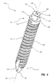
- FIG. 4 is a perspective view of the shaft portion of the bone screw shown in FIG. 2 ;
- FIG. 5 is a top perspective view of the head portion of the bone screw shown in FIG. 2 ;
- FIG. 6 is a bottom perspective view of the head portion of the bone screw shown in FIG. 2 ;
- FIG. 7 is a bottom plan view of the assembled bone screw shown in FIG. 3 ;
- FIGS. 8A-8D are cross-sectional bottom views of alternative embodiments of bone screws
- FIG. 9 is a perspective view of the collar shown in FIG. 2 ;
- FIG. 10 is a perspective view of impregnated fibers being wound on the core shown in FIG. 2 ;
- FIG. 11 is a perspective view of sheets of fibers being wound on the core shown in FIG. 2 ;
- FIG. 12 is a perspective view of a blank that is formed during manufacture of the bone screw shown in FIG. 3 according to one embodiment
- FIG. 13 is a perspective view of a portion of the polyaxial screw shown in FIG. 3 in a partially assembled state
- FIG. 13A is an exploded perspective view of an alternative embodiment of the bone screw shown in FIG. 13 wherein the head and the shaft of the bone screw are integrally formed as a unitary member;
- FIG. 14 is a cross sectional side view of a portion of the assembled polyaxial screw shown in FIG. 1 ;
- FIG. 15 is a cross sectional side view of a portion of an assembled bone screw according to one embodiment
- FIG. 16 is a perspective view of an assembled bone screw according to one embodiment having a ring layer painted thereon;
- FIG. 17 is one embodiment of a fixed bone screw wherein a collar is rigidly secured to the end of the shaft;
- FIG. 18 is an exploded view of the bone screw shown in FIG. 17 ;
- FIG. 19 is a perspective bottom view of the collar shown in FIG. 18 ;
- FIG. 20 is an exploded perspective view of an alternative embodiment of the fixed bone screw shown in FIG. 17 wherein the collar and the shaft of the bone screw are integrally formed as a unitary member.
- polyaxial screw 100 can be used for stabilizing adjacent vertebrae of a spine as part of a procedure for fusing together the adjacent vertebrae.
- Polyaxial screw 100 can also be used for stabilizing a series of consecutive vertebrae for manipulation of the spine to correct spinal deformities such as scoliosis. It is appreciated that polyaxial screw 100 and/or discrete elements thereof can also be used in other procedures for anchoring, manipulating, and/or stabilizing portions of the spine or other bones.
- polyaxial screw 100 comprises an elongated bone screw 102 , a collar 104 pivotally mounted on bone screw 102 , and a fastener 106 selectively engageable with collar 104 to secure polyaxial screw 100 to a stabilizing rod 107 .
- the above identified components of polyaxial screw 100 and their relative interaction will now be discussed in greater detail.
- bone screw 102 comprises an elongated shaft 108 having a head 110 disposed thereon with a core 112 extending longitudinally through shaft 108 and head 110 .
- shaft 108 is elongated and has a proximal end 114 and a spaced apart distal end 116 with a central longitudinal axis 118 extending therebetween.
- Shaft 108 comprises an elongated shaft body 113 and an attachment member 126 formed thereon.
- Shaft body 113 has an exterior surface 122 that extends between proximal end 114 and distal end 116 .
- One or more threads 120 helically encircle and radially outwardly project from exterior surface 122 of shaft 108 along the length thereof.
- the one or more threads 120 can have a variety of different pitches and configurations, and, if desired, can be self tapping.
- Proximal end 114 of shaft body 113 terminates at an end face 132 while distal end 116 of shaft body 113 terminates at a tapered tip 124 .
- End face 132 is typically planar and disposed orthogonal to central longitudinal axis 118 , although this is not required.
- Tapered tip 124 has a substantially conical configuration for ease in penetration into a bone or predrilled hole.
- a cutting edge 125 can also be disposed on the tapered portion of tip 124 to aid in cutting the bone in bone screw embodiments that are self tapping.
- Attachment member 126 centrally projects from end face 132 of shaft body 113 . As discussed below in greater detail, attachment member 126 is used to engage and secure head 110 to shaft 108 . As such, attachment member 126 is sized and shaped so as to fit within a complementary attachment recess 128 disposed on head 110 (see FIG. 6 ). In the embodiment depicted, attachment member 126 has an encircling side wall 130 that proximally extends from end face 132 of shaft body 113 to a terminal end face 134 . End faces 132 and 134 are depicted as being substantially parallel with each other and orthogonal to longitudinal axis 118 , although this is not required. Side wall 130 is depicted as being substantially parallel to longitudinal axis 118 , but this is also not required.
- side wall 130 of attachment member 126 comprises a substantially cylindrical portion 135 and a flat 136 .
- Flat 136 in effect removes a portion of the rounded side of the cylinder portion 135 .
- side wall 130 is formed without a flat.
- Other cross sectional attachment shapes can alternatively be used.
- side wall 130 of attachment member 126 can be oval, polygonal, star shaped, irregular, or the like. Other shapes are also possible.
- shaft 108 includes an internal surface 138 that bounds a first passageway 140 that extends longitudinally through shaft 108 between proximal end 114 and distal end 116 .
- First passageway 140 extends along central longitudinal axis 118 , through terminal end face 134 of attachment member 126 and through tapered tip 124 .
- first passageway 140 has a substantially circular cross-sectional shape. Other shapes can alternatively be used.
- first passageway 140 can be oval shaped, star shaped, polygonal shaped, or the like.
- First passageway 140 can also be symmetrically or non-symmetrically shaped.
- Shaft 108 can be comprised of a radiolucent material that will allow viewing of adjacent bone or other internal structures on an X-ray photograph that are in the viewing path of shaft 108 .
- Using radiolucent material for the shaft 108 will also minimize scattering caused by commonly used metallic or other radiopaque shafts in X-Rays, CAT scans, MRI's, and other types of imaging systems.
- a radiolucent material that can be used in shaft 108 is a biocompatible fiber and adhesive matrix, such as a carbon fiber epoxy matrix. In such a matrix, biocompatible fibers are impregnated with an epoxy resin, molten plastic, or other type of adhesive, then wound about a rod or other object to create many layers wound on top of each other.
- the fibers can be wound one fiber at a time or multiple fibers at a time in a fiber bundle or tow.
- the fibers can be included in a sheet and the sheet wound about the rod.
- Various winding patterns can also be used.
- Many types of biocompatible fibers and adhesives can be used. Methods of manufacturing the shaft 108 and other portions of the bone screw 102 are discussed in more detail below.
- the fibers comprise a continuous high strength, PAN based carbon fiber, 34-700, 12 k (tow), “unsized” and approved for permanent implant.
- unsized it is meant that the fibers have not been coated with a material to improve adhesion of the resin or adhesive.
- Other types or sizes of biocompatible fibers can also be used, such as fiberglass, kevlar or other biocompatible fibers.
- biocompatible epoxies that can be used to bond the fibers include the Master Bond Inc. epoxies EP42HT-2 and EP45HT MED and the Epotek epoxies 301-2 and 375. Other epoxies that are implantable, biocompatible, sterilizable, and have the desired strength properties can also be used.
- biocompatible resins that can be used to bond the fibers include polyetheretherketone (PEEK), polyethylene, polyurethane, polyimide, and polyamide. Other materials can alternatively be used.
- an encircling marker can be included within shaft 108 that is spaced apart from first passageway 140 .
- a biocompatible positioning ring 147 is embedded within shaft 108 between proximal end 114 and distal end 116 .
- positioning ring 147 is substantially orthogonal to and substantially encircles first passageway 140 .
- Positioning ring 147 is comprised of a radiopaque material, such as titanium, stainless steel, an alloy or the like so as to be viewable on an X-Ray photograph.
- the X-Ray image of positioning ring 147 can help the physician determine the position and orientation of bone screw 102 , as described in detail below.
- a thin ring layer can be affixed or otherwise placed on exterior surface 122 in place of or in addition to ring 147 .
- thin ring layer 148 is disposed on exterior surface 122 within threads 120 between proximal end 114 and distal end 116 of shaft 108 so as to substantially encircle first passageway 140 .
- ring layer 148 comprises a radiopaque material that is painted onto threads 120 , as in the depicted embodiment.
- ring layer 148 is painted on a single helical revolution of threads 120 , although more revolutions, complete or partial, can also be used.
- ring layer 148 is comprised of a radiopaque material, such as titanium, stainless steel, an alloy or the like so as to be viewable on an X-Ray photograph.
- positioning ring 147 and/or ring layer 148 are positioned about midway between proximal end 114 and distal end 116 . In other embodiments, positioning ring 147 and/or ring layer 148 are positioned substantially closer to proximal end 114 and in still other embodiments substantially closer to distal end 116 . In other embodiments it is appreciated that two or more positioning rings 147 and/or ring layers 148 can be positioned along shaft 108 at spaced apart locations. Furthermore, in alternative embodiments the marker need not be a ring but can be any desired shape and at any position or orientation that will produce a desired marking.
- head 110 is disposed on proximal end 114 of shaft 108 so as to engage with attachment member 126 .
- head 110 comprises a rounded substantially semi-spherical bottom portion 150 that can bias and rotate against collar 104 .
- Bottom portion 150 has a first end 142 on which a face 144 is formed and a second end 146 .
- a top portion 152 centrally projects from face 144 and is shaped to allow a tool to engage and rotate bone screw 102 .
- An annular neck 154 extends from the second end 146 of bottom portion 150 of head 110 to a bottom surface 156 (see FIG. 6 ).
- Neck 154 has an encircling exterior surface 155 having a substantially concave configuration.
- top portion 152 has an encircling sidewall 158 that extends from face 144 to a top surface 160 .
- Top portion 152 has a polygonal shape so that it can mate with a driver or other tool for tightening and loosening bone screws. Other shapes can also be used.
- a socket can be formed within top surface 160 or on face 144 of bottom portion 150 .
- head 110 includes a central longitudinal axis 162 extending through head 110 between top surface 160 of top portion 152 and bottom surface 156 of neck 154 .
- axis 118 of shaft 108 (see FIG. 4 ) and axis 162 of head 110 are aligned with each other.
- Engagement slot 164 is formed on head 110 .
- Engagement slot 164 comprises a pair of opposing side walls 166 and 168 that are generally disposed in parallel planes and extend to a rounded floor 170 and a back wall 172 .
- Back wall 172 typically intersects with floor 170 at a right angle while back wall 172 is disposed generally parallel to central longitudinal axis 162 at a distance spaced apart therefrom.
- floor 170 need not be rounded but can be flat, V-shaped, or have other configurations. It is appreciated that engagement slot 164 can have a variety of different configurations and merely needs to be sized, shaped, and oriented to permit the desired pivoting of collar 104 and rotation of bone screw 102 as will be discussed below in greater detail.
- attachment recess 128 is formed in bottom surface 156 of head 110 to mate with attachment member 126 of shaft 108 ( FIG. 4 ).
- attachment recess 128 is sized and shaped so as to receive attachment member 126 .
- attachment recess 128 is bounded by an encircling side wall 174 that extends from bottom surface 156 to a floor 176 .
- Attachment recess 128 has a straight section 178 of side wall 174 corresponding to flat 136 of side wall 130 of attachment member 126 .
- attachment member 126 is disposed on head 110 and attachment recess 128 is formed on shaft 108 .
- attachment member 126 and attachment recess 128 can have a variety of different configurations and merely need to be sized, shaped, and oriented to permit attachment member 126 and attachment recess 128 to selectively mate with each other when head 110 and shaft 108 are secured together, as will be discussed below in greater detail.
- head 110 includes an internal surface 180 bounding a second passageway 182 that extends through head 110 .
- Second passageway 182 extends along central longitudinal axis 162 , between top surface 160 and attachment recess 128 (or attachment member 126 , if attachment member 126 is disposed on head 110 ).
- Second passageway 182 can be of the same cross-sectional shape as first passageway 140 or can be of a different shape.
- second passageway 182 has a substantially circular cross sectional shape except for a straight portion 184 on one of the sides. Other shapes are also possible.
- Head 110 can comprise a radiolucent material and/or a radiopaque material.
- head 110 comprises a radiopaque metal, such as titanium, stainless steel, tungsten, alloys, or other biocompatible metals.
- head 110 comprises the same radiolucent material as shaft 113 .
- core 112 comprises a slender rod that extends between a proximal end 200 and an opposing distal end 202 .
- Core 112 is designed to fit within first and second passageways 140 and 182 of assembled shaft 108 and head 110 , respectively.
- Core 112 comprises a head portion 204 at proximal end 200 and a shaft portion 206 at distal end 202 .
- Head portion 204 of core 112 is shaped to fit within second passageway 182 of head 110 and shaft portion 206 is shaped to fit within first passageway 140 of shaft 108 .
- shaft portion 206 has a substantially circular cross section (see FIG. 7 ) to fit within the circularly shaped first passageway 140
- head portion 204 has a substantially circular cross section with a segment removed to form a straight section 208 so as to match the shape of second passageway 182 .
- the cross-sectional shapes of head portion 204 and shaft portion 206 comprise the same shape.
- FIGS. 8A-8D disclose various embodiments of shaft portion 206 having different cross sectional shapes.
- FIG. 8A shows an embodiment in which shaft portion 206 a is oval shaped.
- FIG. 8B shows an embodiment in which shaft portion 206 b is generally star shaped.
- FIG. 8C shows an embodiment in which shaft portion 206 c is generally polygonal shaped.
- head portion 204 and/or shaft portion 206 have a symmetrical cross sectional shape, such as shaft portion 206 c shown in FIG.
- head portion 204 and/or shaft portion 206 have a non-symmetrical cross sectional shape, such as shaft portion 206 d shown in FIG. 8D .
- Head portion 204 and/or shaft portion 206 can also use a combination of curved and linear segments, such as head portion 204 shown in FIG. 2 .
- the aforementioned core shapes are exemplary only and that other shapes can alternatively be used.
- the passageways in bone screw 102 in which core 112 is received can have the same complementary configuration as core 112 .
- One benefit of producing core 112 with a non-circular configuration is that greater engagement can be formed between core 112 and bone screw 102 , thereby minimizing the potential for separation therebetween.
- core 112 has a maximum diameter that is less than about 3 millimeters and more commonly less than about 2 millimeters. Other diameters or widths can also be used.
- Core 112 is typically comprised of a radiopaque material. Examples of such materials that can be used in core 112 are titanium, stainless steel, tungsten, alloys, or other biocompatible metals. In some embodiments, core 112 is comprised of the same material as head 110 .
- One advantage of using a radiopaque material in core 112 while using a radiolucent material in shaft 108 is that only the thin core 112 will be seen on an X-ray during and after implantation of bone screw 102 . This aids the surgeon in positioning bone screw 102 when implanting bone screw 102 , yet allows other internal body structures to be viewed by X-ray during and after bone screw 102 implantation.
- core 112 can be comprised of a radiolucent material, such as those previously discussed with regard to shaft 108 .
- collar 104 comprises a tubular side wall 220 having an interior surface 222 and an exterior surface 224 that each extend between a first end 226 and an opposing second end 228 .
- First end 226 terminates at a terminal end face 230 .
- Interior surface 222 bounds a longitudinal passage 232 that longitudinally extends through collar 104 .
- Internal threads 233 are formed on interior surface 222 at or toward first end 226 .
- Side wall 220 is formed having a pair of channels 234 and 236 that are disposed on opposing sides of side wall 220 and that transversely extend through side wall 220 .
- channels 234 and 236 each have a substantially U-shaped configuration.
- Each channel 234 and 236 has an open mouth 238 that extends through end face 230 and an opposing floor 240 that is rounded.
- Each channel 234 and 236 is configured so that stabilizing rod 107 ( FIG. 1 ) can be received therein.
- floor 240 need not be rounded but can be flat, V-shaped, or have other configurations.
- Each of channels 234 and 236 is also bounded by opposing side surfaces 242 and 244 .
- side surfaces 242 and 244 are shown as being in substantially parallel alignment, in alternative embodiments side surfaces 242 and 244 can be designed to diverge or converge as they project away from floor 240 . Other configurations can also be used.
- Channels 234 and 236 form a portion of a transverse passage that transversely extends through collar 104 , as identified by arrow 246 (see FIG. 1 ).
- collar 104 further comprises a shoulder 248 that downwardly and radially inwardly projects from second end 228 of side wall 220 .
- Shoulder 248 terminates at an inside edge 247 that bounds an opening 249 .
- Opening 249 forms part of a longitudinal passage that also extends through collar 104 , as identified by arrow 232 , and that orthogonally intersect with transverse passage 246 ( FIG. 1 ).
- Shoulder 248 has a tapered interior surface that forms an annular seat 250 .
- bottom portion 150 of head 110 of bone screw 102 rests against seat 250 so that collar 104 can pivot relative to bone screw 102 .
- bottom portion 150 of head 110 has a maximum diameter larger than opening 249 of collar 104 so that head 110 cannot pass therethrough.
- top surface 160 of head 110 projects slightly above floor 240 of channels 234 and 236 of collar 104 .
- stabilizing rod 170 biases against top surface 160 of head 110 so as to wedge head 110 within opening 249 and thereby lock bone screw 102 relative to collar 104 .
- a pin hole 252 transversely extends through side wall 220 and/or shoulder 248 at second end 228 of side wall 220 .
- pin hole 252 is typically disposed orthogonal to transverse passage 246 .
- pin hole 252 is adapted to receive a pin 254 which has a first end 256 and an opposing second end 258 .
- Collar 104 and pin 254 are typically comprised of a radiopaque material such as titanium, stainless steel, tungsten, alloys, or other biocompatible metals. In alternative embodiments, however, collar 104 and/or pin 254 can be comprised of a radiolucent material, such as those previously discussed with regard to shaft 108 .
- fastener 106 comprises a locking screw 270 having an encircling side wall 272 that extends between a top end face 274 and an opposing bottom end face 276 .
- movably attached to bottom end face 276 of locking screw 270 is an alignment cap 278 having a substantially U-shaped channel 280 extending transversally therethrough. Channel 280 is bounded by two side surfaces 286 and 288 .
- Alignment cap 278 is rotatably attached to locking screw 270 so that as locking screw 270 is rotated, alignment cap 278 can remain rotationally stationary so as to bias against rod 107 .
- a helical thread 282 Radially outwardly projecting from side wall 272 of locking screw 270 so as to encircle locking screw 270 is a helical thread 282 .
- Recessed on top surface 274 is a polygonal socket 284 adapted to receive a driver. Threads 282 of locking screw 270 are configured to threadedly engage with internal threads 233 of collar 104 ( FIG. 9 ). Accordingly, once stabilizing rod 107 is disposed within transverse passage 246 of collar 104 , locking screw 270 can be screwed into longitudinal passage 232 of collar 104 so that fastener 106 biases stabilizing rod 107 against head 110 of bone screw 102 .
- stabilizing rod 107 is secured from unwanted movement by being compressed between fastener 106 and head 110 of bone screw 102 and/or between fastener 106 and floor 240 of channels 234 and 236 . Furthermore, as stabilizing rod 107 pushes against head 110 , head 110 is wedged against seat 250 of collar 104 , thereby also locking collar 104 relative to bone screw 102 .
- Collar 104 and fastener 106 are simply one example of a collar and fastener that can be used with bone screw 102 described herein.
- Other collars and associated fasteners can alternatively be used, such as the collars and fasteners described in U.S. patent application Ser. No. 11/863,133, filed Sep. 27, 2007, which is incorporated herein by specific reference.
- core 112 is formed from a radiopaque or radiolucent biocompatible material, such as titanium, stainless steel, tungsten, alloy, or other material. Core 112 can be formed by any conventional method known in the art.
- Blank 292 can be formed in a number of ways.
- blank 292 can be formed by winding fiber impregnated with epoxy resin, molten plastic or other adhesive about core 112 to produce a fiber and adhesive matrix.
- a filament winding process is used as is known in the art. In this process, filaments or fibers 294 are wound under tension over the shaft portion 206 of core 112 . Core 112 rotates while a carriage (not shown) moves back and forth along the longitudinal direction of core 112 , laying down fibers 294 in a desired pattern.
- Fibers 294 are coated with the epoxy resin, molten plastic or other type of adhesive as the fibers 294 are wound about core 112 . If positioning ring 147 is used, it is positioned in its desired location during the filament winding process so that positioning ring 147 becomes enveloped by the outer layers of fibers 294 . The winding process continues until the diameter of the blank 292 is greater than the desired diameter of the finished shaft 108 of bone screw 102 . Blank 292 is then allowed to cure or harden. If required, blank 292 can be placed in an oven during the curing process.
- blank 292 is formed using a roll wrap or table wrap process, as depicted in FIG. 11 .
- one or more sheets 296 of fiber are impregnated with the epoxy resin, molten plastic, or other type of adhesive. If required, the impregnated sheet or sheets 296 are then allowed to partially cure. Once the desired amount of partial curing has been obtained, the sheet or sheets 296 are then wrapped about the shaft portion 206 of core 112 to produce a fiber and adhesive matrix. If positioning ring 147 is used, it is positioned in its desired location during the wrapping process so that positioning ring 147 becomes enveloped by the outer layers of sheets 296 . The wrapping continues until the diameter of the blank 292 is greater than the desired diameter of the finished shaft 108 of bone screw 102 . Blank 292 is then allowed to cure in a similar manner to the filament winding process, described previously.
- non-winding methods can also be used for forming blank 292 about core 112 .
- compression molding or other conventional molding processes can be used to mold a fiber/adhesive mixture about core 112 .
- the fibers can be short fiber pieces that are distributed throughout the adhesive.
- Other known methods can alternatively be used to form blank 292 .
- the head portion 204 of core 112 remains open and uncovered, as shown in FIG. 12 .
- the surface of core 112 can be etched or otherwise abraded before the fibers 294 or sheets 296 are wound thereon. This can be accomplished by sand blasting, rubbing with sandpaper, chemical etching, or other known roughening process, if desired.
- Attachment member 126 and helical threads 120 are then formed on the exterior surface 298 of the blank 292 to further form shaft 108 . This can be accomplished by removing a portion of the exterior surface 298 of the blank 292 by using a grinder, lathe, or other cutting tool as is known in the art. Other methods of forming attachment member 126 and threads 120 can alternatively be used.
- Tapered tip 124 can also be formed at the distal end of the shaft 108 , if desired.
- tapered tip 124 is formed by removing a portion of the exterior surface 298 of the blank 292 . Any other features, such as those needed for self tapping, can also be formed if desired.
- head 110 which has been previously formed, is then attached to the threaded shaft 108 .
- bottom surface 156 of head 110 is positioned adjacent head portion 204 of core 112 so that second passageway 182 aligns with core 112 .
- Head 110 is then advanced toward shaft 108 so that head portion 204 of core 112 is received within second passageway 182 .
- Head 110 is further advanced along core 112 until attachment member 126 is received within attachment recess 128 .
- Head 110 is rigidly secured to core 112 and to shaft 108 by adhesive, laser welding, and/or other securing method known in the art.
- the exposed end of core 112 can be directly welded to head 110 . Any portion of core 112 that extends out of second passageway 182 and past top surface 160 of head 110 can be cut off, if desired.
- ring layer 148 is positioned or painted on or within threads 120 after threads 120 have been formed on exterior surface 122 of shaft 108 , as depicted in FIG. 16 . This can occur anytime after threads 122 have been formed, including before or after head 110 is attached and secured to shaft 108 .
- bone screw 102 is shown as being comprised of a body 290 and core 112 that is positioned therein.
- Body 290 comprises shaft 108 and head 110 .
- shaft 108 and head 110 are integrally formed as a single unitary structure. That is, both shaft 108 and head 110 are milled, cut or otherwise formed from a single blank that is formed about core 112 .
- the entire body 290 is comprised of a radiolucent material, such as those previously discussed with regard to shaft 108 , while core 112 is typically comprised of a radiopaque material but can also be comprised of a radiolucent material.
- positioning ring 147 ( FIG. 15 ) and ring layer 148 ( FIG. 16 ) can also be used with body 290 .
- body 290 can initially be formed by winding a radiolucent fiber/adhesive matrix about a core 112 that is formed from a high strength radiopaque material, such as a metal.
- core 112 is then slid out of body 290 .
- the remaining passageway can then be backfilled by injecting a radiolucent material such as an epoxy or other adhesive within the passageway.
- a radiolucent core can be slid into the passageway and secured in place by an adhesive or other method of securing.
- the entire body and core are radiolucent.
- positioning ring 147 FIG. 15
- ring layer 148 FIG. 16
- the polyaxial screw 100 can be assembled with bone screw 102 as one of its components.
- shaft 108 of assembled bone screw 102 is passed down through longitudinal passage 232 and opening 249 of collar 104 .
- Head 110 of bone screw 102 has a maximum diameter that is greater than the minimum diameter of opening 249 extending through seat 250 of collar 104 .
- head 110 of bone screw 102 rests on seat 250 of collar 104 and is prevented from passing through opening 249 .
- head 110 can freely slide on seat 250 such that bone screw 102 and collar 104 can freely pivot relative to each other.
- pin 254 is advanced into pin hole 252 .
- First end 256 of pin 254 is secured within pin hole 252 such as by welding, adhesive, press fit, or other mechanical engagements, such as threaded engagement.
- second end 258 of pin 254 projects into engagement slot 164 of bone screw 102 .
- pin 254 is spaced apart above floor 170 of engagement slot 164 .
- head 110 is prevented from passing back up through collar 104 .
- Pin 254 also functions to couple bone screw 102 and collar 104 together so that rotation of collar 104 or bone screw 102 also facilitates rotation of the other of the collar 104 or bone screw 102 .
- bone screw 102 can be implanted or removed simply by rotating collar 104 .
- pin 62 can come in a variety of different configurations and can be mounted at a variety of different orientations and locations. Pin 62 can also be comprised of a radiolucent or radiopaque material.
- head 110 is mounted on the collar 104 using pin 254 , as described above, before head 110 is attached and secured to core 112 and shaft 108 .
- fixed bone screw 300 comprises a collar rigidly secured to or formed on the end of a threaded shaft so that the collar cannot pivot relative to the shaft.
- Like elements between bone screw 300 and the prior discussed embodiments are identified by like reference characters.
- bone screw 300 comprises shaft 108 , core 112 , and a collar 302 .
- Core 112 is secured within first passageway 140 of shaft 108 .
- the previously discussed materials, configurations, methods of manufacture and alternatives thereof of shaft 109 and core 112 are also applicable to bone screw 300 .
- collar 302 comprises a base 304 that extends from a first end 306 to a floor 308 .
- Base 304 has an interior surface 309 that bounds an attachment recess 310 extending from floor 308 to a first end face 311 at first end 306 .
- Attachment recess 310 thus has the configuration of a blind socket.
- Interior surface 309 has a substantially circular transverse cross section with a flat 314 formed thereon.
- Attachment recess 310 has a configuration complimentarily to and is configured to receive and secure to attachment member 126 of shaft 108 in the same manner that attachment member 126 is received and secured within attachment recess 128 of head 110 ( FIG. 6 ).
- Floor 308 also has an interior surface 316 that bounds a second passageway 312 that extends through floor 308 so as to communicate with attachment recess 310 .
- Interior surface 316 also has a substantially circularly transverse cross section with a flat 318 formed thereon.
- Second passageway 312 is positioned so that when attachment member 126 is secured within attachment recess 310 , first passageway 140 of shaft 108 is aligned with second passageway 312 . It is also appreciated that second passageway 312 is also configured to receive and secure to head portion 204 of core 112 in the same way that head portion 204 is received and secured within second passageway 182 of head 110 ( FIG. 6 ).
- a pair of spaced apart arms 320 and 321 project from opposing sides of base 304 in substantially parallel alignment.
- Each arm 320 and 321 has an interior surface 322 .
- the opposing interior surfaces bound a substantially U-shaped channel 323 in which stabilizing rod 107 ( FIG. 1 ) can be received.
- each interior surface 322 has a thread portion 324 formed thereon. Thread portions 324 enable locking screw 270 ( FIG. 1 ) or an alternative embodiment thereof to threadedly engage with arms 320 and 321 so as to secure stabilizing rod 107 within channel 323 .
- collar 302 can be comprised of the same materials as previously discussed with regard to collar 104 .
- positioning ring 147 ( FIG. 15 ) and ring layer 148 ( FIG. 16 ), as previously discussed, can again be formed on or within shaft 108 .
- shaft 108 out of a radiolucent material while core 112 and collar 302 are formed from a radiopaque material, bone screw 300 can be properly positioned while limiting unwanted obstructions.
- the thin core 112 can be easily viewed by X-ray to determine proper positioning of the bone screw but the larger shaft 108 is radiolucent so as to not obstruct surrounding structure.
- bone screw 300 is shown as being comprised of a body 330 and core 112 that is positioned therein.
- Body 330 comprises shaft 108 and collar 302 .
- shaft 108 and collar 302 are integrally formed as a single unitary structure. That is, both shaft 108 and collar 302 are milled, cut or otherwise formed from a single blank that is formed about core 112 .
- the entire body 330 is comprised of a radiolucent material, such as those previously discussed with regard to shaft 108
- core 112 is typically comprised of a radiopaque material but can also be comprised of a radiolucent material.
- positioning ring 147 ( FIG. 15 ) and/or ring layer 148 ( FIG. 16 ) can also be used with body 330 .
- core 112 can be removed and replaced with an adhesive or an alternative core.
Abstract
Description
Claims (13)
Priority Applications (11)
| Application Number | Priority Date | Filing Date | Title |
|---|---|---|---|
| US12/208,986 US9408649B2 (en) | 2008-09-11 | 2008-09-11 | Radiolucent screw with radiopaque marker |
| EP09792417A EP2326270B1 (en) | 2008-09-11 | 2009-09-10 | Radiolucent screw with radiopaque marker |
| CA2736891A CA2736891C (en) | 2008-09-11 | 2009-09-10 | Radiolucent screw with radiopaque marker |
| MX2011002706A MX2011002706A (en) | 2008-09-11 | 2009-09-10 | Radiolucent screw with radiopaque marker. |
| US13/063,605 US10194950B2 (en) | 2008-09-11 | 2009-09-10 | Radiolucent screw with radiopaque marker |
| CN2009801449250A CN102209501A (en) | 2008-09-11 | 2009-09-10 | Radiolucent screw with radiopaque marker |
| BRPI0918450A BRPI0918450A2 (en) | 2008-09-11 | 2009-09-10 | radiolucent screw with radiopaque marker |
| JP2011526971A JP5600107B2 (en) | 2008-09-11 | 2009-09-10 | X-ray transparent screw with radiopaque marker |
| AU2009291800A AU2009291800B2 (en) | 2008-09-11 | 2009-09-10 | Radiolucent screw with radiopaque marker |
| PCT/US2009/056508 WO2010030774A1 (en) | 2008-09-11 | 2009-09-10 | Radiolucent screw with radiopaque marker |
| US16/267,198 US20190167310A1 (en) | 2008-09-11 | 2019-02-04 | Radiolucent screw with radiopaque marker |
Applications Claiming Priority (1)
| Application Number | Priority Date | Filing Date | Title |
|---|---|---|---|
| US12/208,986 US9408649B2 (en) | 2008-09-11 | 2008-09-11 | Radiolucent screw with radiopaque marker |
Related Child Applications (2)
| Application Number | Title | Priority Date | Filing Date |
|---|---|---|---|
| PCT/US2009/056508 Continuation-In-Part WO2010030774A1 (en) | 2008-09-11 | 2009-09-10 | Radiolucent screw with radiopaque marker |
| US13/063,605 Continuation-In-Part US10194950B2 (en) | 2008-09-11 | 2009-09-10 | Radiolucent screw with radiopaque marker |
Publications (2)
| Publication Number | Publication Date |
|---|---|
| US20100063550A1 US20100063550A1 (en) | 2010-03-11 |
| US9408649B2 true US9408649B2 (en) | 2016-08-09 |
Family
ID=41354042
Family Applications (3)
| Application Number | Title | Priority Date | Filing Date |
|---|---|---|---|
| US12/208,986 Active 2031-08-14 US9408649B2 (en) | 2008-09-11 | 2008-09-11 | Radiolucent screw with radiopaque marker |
| US13/063,605 Active 2030-11-10 US10194950B2 (en) | 2008-09-11 | 2009-09-10 | Radiolucent screw with radiopaque marker |
| US16/267,198 Abandoned US20190167310A1 (en) | 2008-09-11 | 2019-02-04 | Radiolucent screw with radiopaque marker |
Family Applications After (2)
| Application Number | Title | Priority Date | Filing Date |
|---|---|---|---|
| US13/063,605 Active 2030-11-10 US10194950B2 (en) | 2008-09-11 | 2009-09-10 | Radiolucent screw with radiopaque marker |
| US16/267,198 Abandoned US20190167310A1 (en) | 2008-09-11 | 2019-02-04 | Radiolucent screw with radiopaque marker |
Country Status (9)
| Country | Link |
|---|---|
| US (3) | US9408649B2 (en) |
| EP (1) | EP2326270B1 (en) |
| JP (1) | JP5600107B2 (en) |
| CN (1) | CN102209501A (en) |
| AU (1) | AU2009291800B2 (en) |
| BR (1) | BRPI0918450A2 (en) |
| CA (1) | CA2736891C (en) |
| MX (1) | MX2011002706A (en) |
| WO (1) | WO2010030774A1 (en) |
Cited By (2)
| Publication number | Priority date | Publication date | Assignee | Title |
|---|---|---|---|---|
| US20160089186A1 (en) * | 2013-05-13 | 2016-03-31 | Neo Medical Sa | Orthopedic Implant Kit |
| US20190151000A1 (en) * | 2017-11-21 | 2019-05-23 | Patrick M. Kane | Hybrid radiolucent screw with radiopaque components and radiolucent components and method of manufacture |
Families Citing this family (147)
| Publication number | Priority date | Publication date | Assignee | Title |
|---|---|---|---|---|
| US7833250B2 (en) | 2004-11-10 | 2010-11-16 | Jackson Roger P | Polyaxial bone screw with helically wound capture connection |
| US7862587B2 (en) * | 2004-02-27 | 2011-01-04 | Jackson Roger P | Dynamic stabilization assemblies, tool set and method |
| US8876868B2 (en) | 2002-09-06 | 2014-11-04 | Roger P. Jackson | Helical guide and advancement flange with radially loaded lip |
| US7621918B2 (en) | 2004-11-23 | 2009-11-24 | Jackson Roger P | Spinal fixation tool set and method |
| US7377923B2 (en) | 2003-05-22 | 2008-05-27 | Alphatec Spine, Inc. | Variable angle spinal screw assembly |
| US7766915B2 (en) | 2004-02-27 | 2010-08-03 | Jackson Roger P | Dynamic fixation assemblies with inner core and outer coil-like member |
| US8814911B2 (en) | 2003-06-18 | 2014-08-26 | Roger P. Jackson | Polyaxial bone screw with cam connection and lock and release insert |
| US8936623B2 (en) | 2003-06-18 | 2015-01-20 | Roger P. Jackson | Polyaxial bone screw assembly |
| US7776067B2 (en) | 2005-05-27 | 2010-08-17 | Jackson Roger P | Polyaxial bone screw with shank articulation pressure insert and method |
| US7179261B2 (en) | 2003-12-16 | 2007-02-20 | Depuy Spine, Inc. | Percutaneous access devices and bone anchor assemblies |
| US7527638B2 (en) | 2003-12-16 | 2009-05-05 | Depuy Spine, Inc. | Methods and devices for minimally invasive spinal fixation element placement |
| US11419642B2 (en) | 2003-12-16 | 2022-08-23 | Medos International Sarl | Percutaneous access devices and bone anchor assemblies |
| US11241261B2 (en) | 2005-09-30 | 2022-02-08 | Roger P Jackson | Apparatus and method for soft spinal stabilization using a tensionable cord and releasable end structure |
| US8152810B2 (en) | 2004-11-23 | 2012-04-10 | Jackson Roger P | Spinal fixation tool set and method |
| CA2555868C (en) | 2004-02-27 | 2011-09-06 | Roger P. Jackson | Orthopedic implant rod reduction tool set and method |
| US7160300B2 (en) | 2004-02-27 | 2007-01-09 | Jackson Roger P | Orthopedic implant rod reduction tool set and method |
| US9050148B2 (en) | 2004-02-27 | 2015-06-09 | Roger P. Jackson | Spinal fixation tool attachment structure |
| US8926672B2 (en) | 2004-11-10 | 2015-01-06 | Roger P. Jackson | Splay control closure for open bone anchor |
| US9168069B2 (en) | 2009-06-15 | 2015-10-27 | Roger P. Jackson | Polyaxial bone anchor with pop-on shank and winged insert with lower skirt for engaging a friction fit retainer |
| US9980753B2 (en) | 2009-06-15 | 2018-05-29 | Roger P Jackson | pivotal anchor with snap-in-place insert having rotation blocking extensions |
| US8308782B2 (en) | 2004-11-23 | 2012-11-13 | Jackson Roger P | Bone anchors with longitudinal connecting member engaging inserts and closures for fixation and optional angulation |
| US8556938B2 (en) | 2009-06-15 | 2013-10-15 | Roger P. Jackson | Polyaxial bone anchor with non-pivotable retainer and pop-on shank, some with friction fit |
| US8444681B2 (en) | 2009-06-15 | 2013-05-21 | Roger P. Jackson | Polyaxial bone anchor with pop-on shank, friction fit retainer and winged insert |
| US7901437B2 (en) | 2007-01-26 | 2011-03-08 | Jackson Roger P | Dynamic stabilization member with molded connection |
| US8608797B2 (en) | 2005-03-17 | 2013-12-17 | Valtech Cardio Ltd. | Mitral valve treatment techniques |
| US8951285B2 (en) | 2005-07-05 | 2015-02-10 | Mitralign, Inc. | Tissue anchor, anchoring system and methods of using the same |
| US9974653B2 (en) | 2006-12-05 | 2018-05-22 | Valtech Cardio, Ltd. | Implantation of repair devices in the heart |
| US11259924B2 (en) | 2006-12-05 | 2022-03-01 | Valtech Cardio Ltd. | Implantation of repair devices in the heart |
| CA2670988C (en) | 2006-12-08 | 2014-03-25 | Roger P. Jackson | Tool system for dynamic spinal implants |
| US11660190B2 (en) | 2007-03-13 | 2023-05-30 | Edwards Lifesciences Corporation | Tissue anchors, systems and methods, and devices |
| US9668775B2 (en) * | 2008-06-03 | 2017-06-06 | Jeffrey Scott Smith | Pedicle screw |
| US8986318B2 (en) | 2008-06-03 | 2015-03-24 | Jeffrey Scott Smith | Pedicle depth measuring apparatus |
| US8382829B1 (en) | 2008-03-10 | 2013-02-26 | Mitralign, Inc. | Method to reduce mitral regurgitation by cinching the commissure of the mitral valve |
| EP2296744B1 (en) | 2008-06-16 | 2019-07-31 | Valtech Cardio, Ltd. | Annuloplasty devices |
| CA2739997C (en) | 2008-08-01 | 2013-08-13 | Roger P. Jackson | Longitudinal connecting member with sleeved tensioned cords |
| US9408649B2 (en) * | 2008-09-11 | 2016-08-09 | Innovasis, Inc. | Radiolucent screw with radiopaque marker |
| BRPI0920250A2 (en) * | 2008-10-15 | 2016-11-22 | Smith & Nephew Inc | composite internal fasteners |
| US8715342B2 (en) | 2009-05-07 | 2014-05-06 | Valtech Cardio, Ltd. | Annuloplasty ring with intra-ring anchoring |
| US8911494B2 (en) | 2009-05-04 | 2014-12-16 | Valtech Cardio, Ltd. | Deployment techniques for annuloplasty ring |
| EP2379008B1 (en) | 2008-12-22 | 2021-02-17 | Valtech Cardio, Ltd. | Adjustable annuloplasty devices |
| US9011530B2 (en) | 2008-12-22 | 2015-04-21 | Valtech Cardio, Ltd. | Partially-adjustable annuloplasty structure |
| US10517719B2 (en) | 2008-12-22 | 2019-12-31 | Valtech Cardio, Ltd. | Implantation of repair devices in the heart |
| US8241351B2 (en) | 2008-12-22 | 2012-08-14 | Valtech Cardio, Ltd. | Adjustable partial annuloplasty ring and mechanism therefor |
| US8353956B2 (en) | 2009-02-17 | 2013-01-15 | Valtech Cardio, Ltd. | Actively-engageable movement-restriction mechanism for use with an annuloplasty structure |
| US9968452B2 (en) | 2009-05-04 | 2018-05-15 | Valtech Cardio, Ltd. | Annuloplasty ring delivery cathethers |
| US9668771B2 (en) | 2009-06-15 | 2017-06-06 | Roger P Jackson | Soft stabilization assemblies with off-set connector |
| EP2757988A4 (en) | 2009-06-15 | 2015-08-19 | Jackson Roger P | Polyaxial bone anchor with pop-on shank and winged insert with friction fit compressive collet |
| CN103917181A (en) | 2009-06-15 | 2014-07-09 | 罗杰.P.杰克逊 | Polyaxial bone anchor with pop-on shank and friction fit retainer with low profile edge lock |
| US11229457B2 (en) | 2009-06-15 | 2022-01-25 | Roger P. Jackson | Pivotal bone anchor assembly with insert tool deployment |
| US8998959B2 (en) | 2009-06-15 | 2015-04-07 | Roger P Jackson | Polyaxial bone anchors with pop-on shank, fully constrained friction fit retainer and lock and release insert |
| US8574273B2 (en) | 2009-09-09 | 2013-11-05 | Innovision, Inc. | Bone screws and methods of use thereof |
| US9433439B2 (en) | 2009-09-10 | 2016-09-06 | Innovasis, Inc. | Radiolucent stabilizing rod with radiopaque marker |
| US9180007B2 (en) | 2009-10-29 | 2015-11-10 | Valtech Cardio, Ltd. | Apparatus and method for guide-wire based advancement of an adjustable implant |
| US10098737B2 (en) | 2009-10-29 | 2018-10-16 | Valtech Cardio, Ltd. | Tissue anchor for annuloplasty device |
| US9011520B2 (en) | 2009-10-29 | 2015-04-21 | Valtech Cardio, Ltd. | Tissue anchor for annuloplasty device |
| WO2011067770A1 (en) | 2009-12-02 | 2011-06-09 | Valtech Cardio, Ltd. | Delivery tool for implantation of spool assembly coupled to a helical anchor |
| US8870950B2 (en) | 2009-12-08 | 2014-10-28 | Mitral Tech Ltd. | Rotation-based anchoring of an implant |
| US8801712B2 (en) * | 2010-03-08 | 2014-08-12 | Innovasis, Inc. | Radiolucent bone plate with radiopaque marker |
| US20110264151A1 (en) * | 2010-04-26 | 2011-10-27 | Timothy Davis | Bone fixation device and method of validating its proper placement |
| US11653910B2 (en) | 2010-07-21 | 2023-05-23 | Cardiovalve Ltd. | Helical anchor implantation |
| US9622712B2 (en) | 2010-08-25 | 2017-04-18 | Halifax Biomedical Inc. | Method of detecting movement between an implant and a bone |
| US8903473B2 (en) * | 2010-09-15 | 2014-12-02 | Medtronic, Inc. | Radiopaque markers for implantable medical devices |
| GB2502449A (en) | 2010-11-02 | 2013-11-27 | Roger P Jackson | Polyaxial bone anchor with pop-on shank and pivotable retainer |
| CN102551856B (en) * | 2011-01-24 | 2014-07-09 | 上海锐植医疗器械有限公司 | Internal fixing system capable of dilating wound of spinal column in self-rotation manner |
| US8740949B2 (en) | 2011-02-24 | 2014-06-03 | Spinal Elements, Inc. | Methods and apparatus for stabilizing bone |
| WO2012128825A1 (en) | 2011-03-24 | 2012-09-27 | Jackson Roger P | Polyaxial bone anchor with compound articulation and pop-on shank |
| US9017409B2 (en) * | 2011-04-22 | 2015-04-28 | K2M, Inc. | Spinal interbody spacer with semi-constrained screws |
| US9649490B2 (en) | 2011-06-16 | 2017-05-16 | Cook Medical Technologies Llc | Tip for lead extraction device |
| US10792152B2 (en) | 2011-06-23 | 2020-10-06 | Valtech Cardio, Ltd. | Closed band for percutaneous annuloplasty |
| ES2418604T3 (en) * | 2011-08-18 | 2013-08-14 | Biedermann Technologies Gmbh & Co. Kg | Polyaxial bone anchoring device |
| US9173683B2 (en) | 2011-08-31 | 2015-11-03 | DePuy Synthes Products, Inc. | Revisable orthopedic anchor and methods of use |
| US9060818B2 (en) | 2011-09-01 | 2015-06-23 | DePuy Synthes Products, Inc. | Bone implants |
| USD739935S1 (en) | 2011-10-26 | 2015-09-29 | Spinal Elements, Inc. | Interbody bone implant |
| US9622788B2 (en) * | 2011-11-02 | 2017-04-18 | Warsaw Orthopedic, Inc. | Implant assembly with a rigid interface |
| US8858623B2 (en) | 2011-11-04 | 2014-10-14 | Valtech Cardio, Ltd. | Implant having multiple rotational assemblies |
| EP3656434B1 (en) | 2011-11-08 | 2021-10-20 | Valtech Cardio, Ltd. | Controlled steering functionality for implant-delivery tool |
| US8911479B2 (en) | 2012-01-10 | 2014-12-16 | Roger P. Jackson | Multi-start closures for open implants |
| EP2667352B1 (en) * | 2012-05-23 | 2020-01-01 | Stryker European Holdings I, LLC | Virtual 3D overlay as reduction aid for complex fractures |
| US9572598B2 (en) * | 2012-08-09 | 2017-02-21 | Spine Craft, LLC | Uniplanar surgical screw assembly |
| WO2014052818A1 (en) | 2012-09-29 | 2014-04-03 | Mitralign, Inc. | Plication lock delivery system and method of use thereof |
| US10376266B2 (en) | 2012-10-23 | 2019-08-13 | Valtech Cardio, Ltd. | Percutaneous tissue anchor techniques |
| WO2014064694A2 (en) | 2012-10-23 | 2014-05-01 | Valtech Cardio, Ltd. | Controlled steering functionality for implant-delivery tool |
| US8911478B2 (en) | 2012-11-21 | 2014-12-16 | Roger P. Jackson | Splay control closure for open bone anchor |
| EP2740427B1 (en) | 2012-12-05 | 2020-03-11 | Biedermann Technologies GmbH & Co. KG | Dynamic bone anchor and method of manufacturing the same |
| US9730793B2 (en) | 2012-12-06 | 2017-08-15 | Valtech Cardio, Ltd. | Techniques for guide-wire based advancement of a tool |
| EP2948103B1 (en) | 2013-01-24 | 2022-12-07 | Cardiovalve Ltd | Ventricularly-anchored prosthetic valves |
| US10058354B2 (en) | 2013-01-28 | 2018-08-28 | Roger P. Jackson | Pivotal bone anchor assembly with frictional shank head seating surfaces |
| US8852239B2 (en) | 2013-02-15 | 2014-10-07 | Roger P Jackson | Sagittal angle screw with integral shank and receiver |
| EP2961351B1 (en) | 2013-02-26 | 2018-11-28 | Mitralign, Inc. | Devices for percutaneous tricuspid valve repair |
| US9421044B2 (en) | 2013-03-14 | 2016-08-23 | Spinal Elements, Inc. | Apparatus for bone stabilization and distraction and methods of use |
| US10449333B2 (en) | 2013-03-14 | 2019-10-22 | Valtech Cardio, Ltd. | Guidewire feeder |
| US9724195B2 (en) | 2013-03-15 | 2017-08-08 | Mitralign, Inc. | Translation catheters and systems |
| AU2014237911B2 (en) | 2013-03-15 | 2018-02-15 | Innovision, Inc. | Bone screws and methods of use thereof |
| JP2014210082A (en) * | 2013-04-19 | 2014-11-13 | サンエー精工株式会社 | Bone fixing screw set |
| DE102013107170A1 (en) | 2013-07-08 | 2015-01-22 | Aesculap Ag | bone screw |
| US10070857B2 (en) | 2013-08-31 | 2018-09-11 | Mitralign, Inc. | Devices and methods for locating and implanting tissue anchors at mitral valve commissure |
| EP3038552B1 (en) | 2013-09-01 | 2020-08-12 | Carbofix In Orthopedics LLC | Composite material spinal implant |
| US9839450B2 (en) | 2013-09-27 | 2017-12-12 | Spinal Elements, Inc. | Device and method for reinforcement of a facet |
| US9456855B2 (en) | 2013-09-27 | 2016-10-04 | Spinal Elements, Inc. | Method of placing an implant between bone portions |
| US10299793B2 (en) | 2013-10-23 | 2019-05-28 | Valtech Cardio, Ltd. | Anchor magazine |
| US9566092B2 (en) | 2013-10-29 | 2017-02-14 | Roger P. Jackson | Cervical bone anchor with collet retainer and outer locking sleeve |
| US9717533B2 (en) | 2013-12-12 | 2017-08-01 | Roger P. Jackson | Bone anchor closure pivot-splay control flange form guide and advancement structure |
| US9610162B2 (en) | 2013-12-26 | 2017-04-04 | Valtech Cardio, Ltd. | Implantation of flexible implant |
| US9451993B2 (en) | 2014-01-09 | 2016-09-27 | Roger P. Jackson | Bi-radial pop-on cervical bone anchor |
| US9597119B2 (en) | 2014-06-04 | 2017-03-21 | Roger P. Jackson | Polyaxial bone anchor with polymer sleeve |
| CN103961169A (en) * | 2014-06-04 | 2014-08-06 | 池永龙 | Percutaneous dynamical articular process internal fixation device with location function |
| US10064658B2 (en) | 2014-06-04 | 2018-09-04 | Roger P. Jackson | Polyaxial bone anchor with insert guides |
| US10314618B2 (en) * | 2014-07-25 | 2019-06-11 | The General Hospital Corporation | System and method for an external hip fixator |
| ES2557955B1 (en) * | 2014-07-29 | 2016-11-10 | Inael Electrical Sytems, S.A. | Eject fuse circuit breaker |
| US9883898B2 (en) | 2014-08-07 | 2018-02-06 | Jeffrey Scott Smith | Pedicle screw with electro-conductive coating or portion |
| US10470890B2 (en) | 2014-08-12 | 2019-11-12 | Neutin Orthopedics, LLC | Titanium plasma coated medical grade thermoplastic or polymer proximal and distal interphalangeal toe implant |
| US20160045324A1 (en) * | 2014-08-12 | 2016-02-18 | Neutin Orthopedics, LLC | Titanium plasma coated medical grade thermoplastic or polymer proximal and distal interphalangeal toe implant |
| US11478275B2 (en) | 2014-09-17 | 2022-10-25 | Spinal Elements, Inc. | Flexible fastening band connector |
| US10195030B2 (en) | 2014-10-14 | 2019-02-05 | Valtech Cardio, Ltd. | Leaflet-restraining techniques |
| EP3253333B1 (en) | 2015-02-05 | 2024-04-03 | Cardiovalve Ltd | Prosthetic valve with axially-sliding frames |
| US20160256269A1 (en) | 2015-03-05 | 2016-09-08 | Mitralign, Inc. | Devices for treating paravalvular leakage and methods use thereof |
| CN114515173A (en) | 2015-04-30 | 2022-05-20 | 瓦尔泰克卡迪欧有限公司 | Valvuloplasty techniques |
| EP3115008B1 (en) * | 2015-07-09 | 2019-06-19 | Silony Medical International AG | Bone anchoring element |
| US10136929B2 (en) * | 2015-07-13 | 2018-11-27 | IntraFuse, LLC | Flexible bone implant |
| EP3184063B1 (en) * | 2015-12-21 | 2019-07-10 | Biedermann Technologies GmbH & Co. KG | Polyaxial bone anchoring device |
| WO2017117370A2 (en) | 2015-12-30 | 2017-07-06 | Mitralign, Inc. | System and method for reducing tricuspid regurgitation |
| US10751182B2 (en) | 2015-12-30 | 2020-08-25 | Edwards Lifesciences Corporation | System and method for reshaping right heart |
| US10531866B2 (en) | 2016-02-16 | 2020-01-14 | Cardiovalve Ltd. | Techniques for providing a replacement valve and transseptal communication |
| US10702274B2 (en) | 2016-05-26 | 2020-07-07 | Edwards Lifesciences Corporation | Method and system for closing left atrial appendage |
| GB201611910D0 (en) | 2016-07-08 | 2016-08-24 | Valtech Cardio Ltd | Adjustable annuloplasty device with alternating peaks and troughs |
| WO2018029680A1 (en) | 2016-08-10 | 2018-02-15 | Mitraltech Ltd. | Prosthetic valve with concentric frames |
| US20200038646A1 (en) * | 2017-03-14 | 2020-02-06 | Spinal Generations, Llc | Fluid delivery device and bone screw |
| US11045627B2 (en) | 2017-04-18 | 2021-06-29 | Edwards Lifesciences Corporation | Catheter system with linear actuation control mechanism |
| WO2018200495A1 (en) * | 2017-04-25 | 2018-11-01 | Shaun Tanner | Tissue fixation systems |
| US10507043B1 (en) * | 2017-10-11 | 2019-12-17 | Seaspine Orthopedics Corporation | Collet for a polyaxial screw assembly |
| US10835221B2 (en) | 2017-11-02 | 2020-11-17 | Valtech Cardio, Ltd. | Implant-cinching devices and systems |
| US11135062B2 (en) | 2017-11-20 | 2021-10-05 | Valtech Cardio Ltd. | Cinching of dilated heart muscle |
| CN111655200B (en) | 2018-01-24 | 2023-07-14 | 爱德华兹生命科学创新(以色列)有限公司 | Contraction of annuloplasty structures |
| WO2019145941A1 (en) | 2018-01-26 | 2019-08-01 | Valtech Cardio, Ltd. | Techniques for facilitating heart valve tethering and chord replacement |
| WO2019152502A2 (en) * | 2018-01-30 | 2019-08-08 | Orthopediatrics Corp. | Vertebral body tethering with suture loops |
| JP6437699B1 (en) * | 2018-05-02 | 2018-12-12 | 医療法人香和会おおたわ歯科医院 | Method and system for identifying spatial position of scanning jig and implant |
| US10966736B2 (en) * | 2018-05-21 | 2021-04-06 | Warsaw Orthopedic, Inc. | Spinal implant system and methods of use |
| CA3106104A1 (en) | 2018-07-12 | 2020-01-16 | Valtech Cardio, Ltd. | Annuloplasty systems and locking tools therefor |
| US11457959B2 (en) | 2019-05-22 | 2022-10-04 | Spinal Elements, Inc. | Bone tie and bone tie inserter |
| EP3972503A4 (en) | 2019-05-22 | 2023-02-01 | Spinal Elements Inc. | Bone tie and bone tie inserter |
| CN114786621A (en) | 2019-10-29 | 2022-07-22 | 爱德华兹生命科学创新(以色列)有限公司 | Annuloplasty and tissue anchoring techniques |
| US11304733B2 (en) | 2020-02-14 | 2022-04-19 | Spinal Elements, Inc. | Bone tie methods |
| US20210346065A1 (en) * | 2020-04-09 | 2021-11-11 | Globus Medical, Inc. | Spinal screw |
| JP7446965B2 (en) * | 2020-09-29 | 2024-03-11 | グローブライド株式会社 | Spinal fixation rod |
| US11861822B2 (en) * | 2021-06-24 | 2024-01-02 | Saudi Arabian Oil Company | Image recognition device and method for retrieving information on a marker |
| US20230165613A1 (en) * | 2021-11-29 | 2023-06-01 | Warsaw Orthopedic, Inc. | Continuous fiber bone screw and method of manufacture |
| US11871967B1 (en) | 2023-02-28 | 2024-01-16 | Vertrae Medical Consulting, LLC | Pedicle screw device and method of use |
Citations (127)
| Publication number | Priority date | Publication date | Assignee | Title |
|---|---|---|---|---|
| US1828287A (en) * | 1928-03-09 | 1931-10-20 | Weldbuilt Corp | Method of making bolts and similar connecting devices |
| US2405909A (en) * | 1942-08-22 | 1946-08-13 | Hercules Powder Co Ltd | Method of producing threaded spiral tubes |
| US3455360A (en) * | 1967-07-12 | 1969-07-15 | Leon Simons | Vibration-resistant screw |
| US4063838A (en) * | 1976-05-07 | 1977-12-20 | Fiber Glass Systems, Inc. | Rod construction and method of forming the same |
| US4265981A (en) * | 1977-05-17 | 1981-05-05 | Commonwealth Scientific And Industrial Research Organization | Impact-resisting composites |
| US4307979A (en) * | 1978-12-14 | 1981-12-29 | Ppg Industries, Inc. | Mine roof bolt and end cap |
| US4329743A (en) | 1979-04-27 | 1982-05-18 | College Of Medicine And Dentistry Of New Jersey | Bio-absorbable composite tissue scaffold |
| US4403606A (en) | 1980-05-09 | 1983-09-13 | The Regents Of The University Of California | Compatible internal bone fixation plate |
| US4512038A (en) | 1979-04-27 | 1985-04-23 | University Of Medicine And Dentistry Of New Jersey | Bio-absorbable composite tissue scaffold |
| US4623290A (en) * | 1983-02-28 | 1986-11-18 | Asahi Kasei Kogyo Kabushiki Kaisha | Externally threaded fiber-reinforced plastic member and a method of producing the same |
| US4778637A (en) * | 1984-06-18 | 1988-10-18 | Tiodize Company, Inc, | Method of forming a composite fastener |
| US4863330A (en) * | 1987-07-15 | 1989-09-05 | Northrop Corporation | Composite fastener and method of manufacture |
| US4863470A (en) | 1985-03-19 | 1989-09-05 | Medical Engineering Corporation | Identification marker for a breast prosthesis |
| US5084051A (en) * | 1986-11-03 | 1992-01-28 | Toermaelae Pertti | Layered surgical biocomposite material |
| US5127783A (en) * | 1989-05-25 | 1992-07-07 | The B.F. Goodrich Company | Carbon/carbon composite fasteners |
| US5209888A (en) * | 1988-12-16 | 1993-05-11 | Fukuvi Chemical Industry Co., Ltd. | Method for producing frp screw-like fastening elements |
| US5246655A (en) * | 1991-04-30 | 1993-09-21 | The Young Industries, Inc. | Method of making thermoplastic valve rotors |
| WO1994004095A1 (en) | 1992-08-20 | 1994-03-03 | Lipomatrix, Incorporated | Penile implant with triglyceride fill |
| US5366773A (en) * | 1992-12-21 | 1994-11-22 | Xerox Corporation | Tubular pultruded member having uniform wall thickness |
| US5466237A (en) | 1993-11-19 | 1995-11-14 | Cross Medical Products, Inc. | Variable locking stabilizer anchor seat and screw |
| US5474555A (en) | 1990-04-26 | 1995-12-12 | Cross Medical Products | Spinal implant system |
| US5540870A (en) * | 1992-07-14 | 1996-07-30 | Composite Development Corporation | Structural element formed of a fiber reinforced thermoplastic material and method of manufacture |
| DE4443051A1 (en) | 1994-12-05 | 1996-10-02 | Friedrich Schmitt | Jaw implant also suitable for general bone surgery |
| US5676146A (en) | 1996-09-13 | 1997-10-14 | Osteotech, Inc. | Surgical implant containing a resorbable radiopaque marker and method of locating such within a body |
| US5807051A (en) | 1995-09-18 | 1998-09-15 | United Industries Corporation | Dielectric adhesive insert anchor |
| GB2294399B (en) | 1994-10-28 | 1999-03-24 | Jbs Sa | Bone Screw Devices |
| US5951556A (en) * | 1996-05-15 | 1999-09-14 | Orthofix S.R.L. | Compact external fixation device |
| US6059769A (en) * | 1998-10-02 | 2000-05-09 | Medtronic, Inc. | Medical catheter with grooved soft distal segment |
| US6063090A (en) | 1996-12-12 | 2000-05-16 | Synthes (U.S.A.) | Device for connecting a longitudinal support to a pedicle screw |
| US6099528A (en) | 1997-05-29 | 2000-08-08 | Sofamor S.N.C. | Vertebral rod for spinal osteosynthesis instrumentation and osteosynthesis instrumentation, including said rod |
| US6113826A (en) * | 1997-10-02 | 2000-09-05 | Sowa Co., Ltd | Manufacturing method for U-bolts |
| US6117173A (en) | 1995-12-07 | 2000-09-12 | Aesculap Ag & Co., Kg | Orthopaedic fixing system |
| US6174329B1 (en) * | 1996-08-22 | 2001-01-16 | Advanced Cardiovascular Systems, Inc. | Protective coating for a stent with intermediate radiopaque coating |
| US6203568B1 (en) | 1996-04-05 | 2001-03-20 | Medtronic, Inc. | Endoluminal prostheses having position indicating markers |
| US6214921B1 (en) * | 1999-07-22 | 2001-04-10 | Xerox Corporation | Electrical component |
| US6248105B1 (en) | 1997-05-17 | 2001-06-19 | Synthes (U.S.A.) | Device for connecting a longitudinal support with a pedicle screw |
| US6280442B1 (en) | 1999-09-01 | 2001-08-28 | Sdgi Holdings, Inc. | Multi-axial bone screw assembly |
| US6302630B1 (en) | 2000-04-18 | 2001-10-16 | Lockheed Martin | Fastener with recessed head and head insert |
| US6340367B1 (en) | 1997-08-01 | 2002-01-22 | Boston Scientific Scimed, Inc. | Radiopaque markers and methods of using the same |
| US6342055B1 (en) | 1999-04-29 | 2002-01-29 | Theken Surgical Llc | Bone fixation system |
| US6371957B1 (en) | 1997-01-22 | 2002-04-16 | Synthes (Usa) | Device for connecting a longitudinal bar to a pedicle screw |
| DE10065799C1 (en) | 2000-12-30 | 2002-04-25 | Rehau Ag & Co | Skull drainage screw has threaded hollow shaft provided with multi-sided inner profile for reception of multi-sided insertion tool |
| US6423067B1 (en) | 1999-04-29 | 2002-07-23 | Theken Surgical Llc | Nonlinear lag screw with captive driving device |
| US20020123751A1 (en) | 2001-03-02 | 2002-09-05 | Fallin T. Wade | Two-part orthopedic fastener |
| US20020133158A1 (en) | 2001-03-15 | 2002-09-19 | Saint Martin Pierre Henri | Anchoring member with packer |
| US6471705B1 (en) | 1999-08-02 | 2002-10-29 | Lutz Biedermann | Bone screw |
| US20030078583A1 (en) | 2001-10-23 | 2003-04-24 | Biedermann Motech Gmbh | Bone fixing device |
| US6565567B1 (en) | 1996-12-20 | 2003-05-20 | Thomas T. Haider | Pedicle screw for osteosynthesis |
| US6575975B2 (en) | 2000-04-19 | 2003-06-10 | Synthes (U.S.A.) | Bone fixation method |
| US6599290B2 (en) | 2001-04-17 | 2003-07-29 | Ebi, L.P. | Anterior cervical plating system and associated method |
| US6641586B2 (en) | 2002-02-01 | 2003-11-04 | Depuy Acromed, Inc. | Closure system for spinal fixation instrumentation |
| US6679883B2 (en) | 2001-10-31 | 2004-01-20 | Ortho Development Corporation | Cervical plate for stabilizing the human spine |
| US20040034430A1 (en) | 2002-06-14 | 2004-02-19 | Falahee Mark H. | Anatomic vertebral cage |
| US6712852B1 (en) | 2002-09-30 | 2004-03-30 | Depuy Spine, Inc. | Laminoplasty cage |
| US6740086B2 (en) | 2002-04-18 | 2004-05-25 | Spinal Innovations, Llc | Screw and rod fixation assembly and device |
| US20040127904A1 (en) | 2002-12-31 | 2004-07-01 | Konieczynski David D. | Bone plate and resilient screw system allowing bi-directional assembly |
| US20040143265A1 (en) | 2002-10-30 | 2004-07-22 | Landry Michael E. | Spinal stabilization systems and methods using minimally invasive surgical procedures |
| US20040199251A1 (en) | 2003-04-01 | 2004-10-07 | Sdgi Holdings, Inc. | Interbody fusion device |
| US20040210316A1 (en) | 2003-04-15 | 2004-10-21 | Richard King | Implantable orthopaedic device and method for making the same |
| US20040210226A1 (en) | 2000-10-20 | 2004-10-21 | Trieu Hai H. | Anchoring devices and implants for intervertebral disc augmentation |
| US20040215195A1 (en) | 2003-04-25 | 2004-10-28 | Sdgi Holdings, Inc. | Non-metallic orthopedic plate |
| US20040243129A1 (en) | 2003-05-28 | 2004-12-02 | Missoum Moumene | Double helical threaded bone screw |
| US6837905B1 (en) | 2002-09-26 | 2005-01-04 | Daniel M. Lieberman | Spinal vertebral fusion implant and method |
| US20050187550A1 (en) | 2003-12-01 | 2005-08-25 | Grusin N. K. | Humeral nail |
| US20050187555A1 (en) | 2004-02-24 | 2005-08-25 | Biedermann Motech Gmbh | Bone anchoring element |
| US20050203516A1 (en) | 2004-03-03 | 2005-09-15 | Biedermann Motech Gmbh | Anchoring element and stabilization device for the dynamic stabilization of vertebrae or bones using such anchoring elements |
| US20050203517A1 (en) | 2003-09-24 | 2005-09-15 | N Spine, Inc. | Spinal stabilization device |
| US20050203519A1 (en) | 2004-03-09 | 2005-09-15 | Jurgen Harms | Rod-like element for application in spinal or trauma surgery, and stabilization device with such a rod-like element |
| US20050216081A1 (en) | 2004-03-29 | 2005-09-29 | Taylor Brett A | Arthroplasty spinal prosthesis and insertion device |
| JP2005270250A (en) | 2004-03-24 | 2005-10-06 | Kawasumi Lab Inc | Tube for medical use |
| US20050228388A1 (en) | 2004-03-30 | 2005-10-13 | Darrel Brodke | Double lead bone screw |
| US20050228479A1 (en) | 2001-11-29 | 2005-10-13 | Cook Incorporated | Medical device delivery system |
| US6955513B2 (en) * | 2002-03-21 | 2005-10-18 | California Polytechnic State University Foundation | Flexible fastener |
| US6974480B2 (en) | 2001-05-03 | 2005-12-13 | Synthes (Usa) | Intervertebral implant for transforaminal posterior lumbar interbody fusion procedure |
| US20060041259A1 (en) | 2003-05-23 | 2006-02-23 | Paul David C | Spine stabilization system |
| US20060084986A1 (en) | 2004-09-30 | 2006-04-20 | Depuy Spine, Inc. | Instrument and method for the insertion and alignment of an intervertebral implant |
| US20060085072A1 (en) | 2004-04-22 | 2006-04-20 | Archus Orthopedics, Inc. | Implantable orthopedic device component selection instrument and methods |
| US20060089644A1 (en) | 2004-10-27 | 2006-04-27 | Felix Brent A | Spinal stabilizing system |
| US20060142758A1 (en) | 2002-09-11 | 2006-06-29 | Dominique Petit | Linking element for dynamically stabilizing a spinal fixing system and spinal fixing system comprising same |
| US20060149228A1 (en) | 2003-06-12 | 2006-07-06 | Stratec Medical | Device for dynamically stabilizing bones or bone fragments, especially thoracic vertebral bodies |
| JP2006187658A (en) | 1994-02-09 | 2006-07-20 | Boston Scientific Scimed Inc | Bifurcated endoluminal prosthesis |
| US20060195093A1 (en) | 2003-09-24 | 2006-08-31 | Tae-Ahn Jahng | Method and apparatus for flexible fixation of a spine |
| US20060200140A1 (en) | 2001-02-28 | 2006-09-07 | Lange Eric C | Flexible spine stabilization systems |
| US20060235410A1 (en) | 2005-04-15 | 2006-10-19 | Ralph James D | Surgical expansion fasteners |
| US20060247638A1 (en) | 2005-04-29 | 2006-11-02 | Sdgi Holdings, Inc. | Composite spinal fixation systems |
| US20060276788A1 (en) | 2005-05-26 | 2006-12-07 | Amedica Corporation | Osteoconductive spinal fixation system |
| US7150594B2 (en) * | 2004-03-09 | 2006-12-19 | The Boeing Company | Hybrid fastener apparatus and method for fastening |
| US7192447B2 (en) | 2002-12-19 | 2007-03-20 | Synthes (Usa) | Intervertebral implant |
| US20070123879A1 (en) | 2003-02-05 | 2007-05-31 | Pioneer Laboratories, Inc. | Bone plate system |
| US7235079B2 (en) | 2004-11-18 | 2007-06-26 | Acumed Llc | Composite bone fasteners |
| US7235290B2 (en) * | 2001-06-12 | 2007-06-26 | Stick Tech Oy | Prepreg, a composite and their uses |
| US20070156145A1 (en) | 2005-12-30 | 2007-07-05 | Kentomia, Llc | Therapeutic constructions, spinal plates, cervical plates, hooks and screws |
| US7273481B2 (en) | 2002-10-28 | 2007-09-25 | Blackstone Medical, Inc. | Bone plate assembly provided with screw locking mechanisms |
| US20070233073A1 (en) | 2006-03-02 | 2007-10-04 | Sdgi Holdings, Inc. | Spinal rod characterized by a time-varying stiffness |
| US20070233071A1 (en) | 2006-03-01 | 2007-10-04 | Sdgi Holdings, Inc. | Bone anchors having two or more portions exhibiting different performance characteristics and method of forming the same |
| US20070250167A1 (en) | 2003-04-21 | 2007-10-25 | Rsb Spine Llc | Spine implants |
| WO2007127845A2 (en) | 2006-04-28 | 2007-11-08 | Warsaw Orthopedic, Inc. | Radiolucent bone plate systems and methods of use |
| JP2007307368A (en) | 2006-05-15 | 2007-11-29 | Biomet Spain Orthopaedics Sl | Surgical screw system and its use |
| US7318825B2 (en) | 2003-12-22 | 2008-01-15 | Life Spine Llc | Dynamic cervical plates and cervical plate constructs |
| US20080065070A1 (en) | 2002-02-01 | 2008-03-13 | Freid James M | Spinal plate system for stabilizing a portion of a spine |
| US20080077133A1 (en) | 2006-09-27 | 2008-03-27 | Depuy Products, Inc. | Flexible bone fixation device |
| US20080082103A1 (en) | 2006-06-16 | 2008-04-03 | Alphatec Spine, Inc. | Systems and methods for manipulating and/or installing a pedicle screw |
| US20080086127A1 (en) | 2006-08-31 | 2008-04-10 | Warsaw Orthopedic, Inc. | Polymer Rods For Spinal Applications |
| US20080083613A1 (en) | 2006-10-06 | 2008-04-10 | Nelson Oi | Port structures for non-rigid bone plates |
| US20080086129A1 (en) | 2006-09-14 | 2008-04-10 | Warsaw Orthopedic, Inc. | Hybrid bone fixation apparatus |
| US20080091214A1 (en) | 2005-01-26 | 2008-04-17 | Richelsoph Marc E | Self-contouring spinal rod |
| US20080097432A1 (en) | 2006-09-27 | 2008-04-24 | Depuy Products, Inc. | Flexible bone fixation device |
| US20080125777A1 (en) | 2006-11-27 | 2008-05-29 | Warsaw Orthopedic, Inc. | Vertebral Stabilizer Having Adjustable Rigidity |
| FR2899787B1 (en) | 2006-04-12 | 2008-06-20 | Neuro France Implants Sarl | SCREWS FOR THE REDUCTION OF A FRACTURE OF APOPHYSIS ODONTOIRE |
| US20080154367A1 (en) | 2006-12-21 | 2008-06-26 | Warsaw Orthopedic, Inc. | Methods for positioning a load-bearing component of an orthopedic implant device by inserting a malleable device that hardens in vivo |
| US20080154306A1 (en) | 2006-12-26 | 2008-06-26 | Warsaw Orthopedic, Inc. | Sacral Reconstruction Fixation Device |
| US20080243185A1 (en) | 2006-09-27 | 2008-10-02 | Felix Brent A | Spinal stabilizing system |
| US20090082810A1 (en) | 2007-09-21 | 2009-03-26 | Jmea Corporation | Spinal Fixation with Selectively Applied Bone Growth Promoting Agent |
| US20090093819A1 (en) | 2007-10-05 | 2009-04-09 | Abhijeet Joshi | Anisotropic spinal stabilization rod |
| US20090093844A1 (en) | 2005-09-30 | 2009-04-09 | Jackson Roger P | Elastic covered dynamic stabilization connector and assembly |
| US7524190B2 (en) * | 2006-01-30 | 2009-04-28 | K1C2 | Fabric-wrapped craft wire and process for manufacturing same |
| US20090112265A1 (en) | 2007-10-24 | 2009-04-30 | Zimmer Spine, Inc. | Flexible member for use in a spinal column and method for making |
| US20090240284A1 (en) | 2008-03-24 | 2009-09-24 | David Scott Randol | Stabilization rods |
| US20090275983A1 (en) | 2008-05-05 | 2009-11-05 | Warsaw Orthopedic, Inc. | Dynamic stabilization rod |
| US20090326582A1 (en) | 2008-04-10 | 2009-12-31 | Marcus Songer | Dynamic Rod |
| US20100042215A1 (en) * | 2008-08-13 | 2010-02-18 | Stalcup Gregory C | Orthopaedic implant |
| US20100063550A1 (en) | 2008-09-11 | 2010-03-11 | Innovasis, Inc, | Radiolucent screw with radiopaque marker |
| US20100114167A1 (en) | 2008-10-31 | 2010-05-06 | Warsaw Orthopedic, Inc. | Transition rod |
| US20100160967A1 (en) | 2008-12-22 | 2010-06-24 | Joseph Capozzoli | Variable tension spine fixation rod |
| US7966711B2 (en) * | 2007-08-14 | 2011-06-28 | The Boeing Company | Method and apparatus for fastening components using a composite two-piece fastening system |
| US20120109207A1 (en) | 2010-10-29 | 2012-05-03 | Warsaw Orthopedic, Inc. | Enhanced Interfacial Conformance for a Composite Rod for Spinal Implant Systems with Higher Modulus Core and Lower Modulus Polymeric Sleeve |
| US8475505B2 (en) * | 2008-08-13 | 2013-07-02 | Smed-Ta/Td, Llc | Orthopaedic screws |
Family Cites Families (14)
| Publication number | Priority date | Publication date | Assignee | Title |
|---|---|---|---|---|
| US2680442A (en) * | 1952-04-04 | 1954-06-08 | Frank L Linzmayer | Disposable suppository casing |
| US7833256B2 (en) | 2004-04-16 | 2010-11-16 | Biedermann Motech Gmbh | Elastic element for the use in a stabilization device for bones and vertebrae and method for the manufacture of such elastic element |
| US7927348B2 (en) * | 2006-10-10 | 2011-04-19 | Codman & Shurtleff, Inc. | Stretch resistant coil device |
| US8292925B2 (en) | 2007-06-19 | 2012-10-23 | Zimmer Spine, Inc. | Flexible member with variable flexibility for providing dynamic stability to a spine |
| JP5369540B2 (en) * | 2007-08-29 | 2013-12-18 | 住友化学株式会社 | Alkali metal fluoride dispersion and method for producing fluorine-containing organic compound using the same |
| US9232968B2 (en) | 2007-12-19 | 2016-01-12 | DePuy Synthes Products, Inc. | Polymeric pedicle rods and methods of manufacturing |
| US20090234388A1 (en) | 2008-03-15 | 2009-09-17 | Warsaw Orthopedic, Inc. | Spinal Stabilization Connecting Element and System |
| US20090248083A1 (en) | 2008-03-26 | 2009-10-01 | Warsaw Orthopedic, Inc. | Elongated connecting element with varying modulus of elasticity |
| US9017384B2 (en) | 2008-05-13 | 2015-04-28 | Stryker Spine | Composite spinal rod |
| EP2160988B1 (en) | 2008-09-04 | 2012-12-26 | Biedermann Technologies GmbH & Co. KG | Rod-shaped implant in particular for stabilizing the spinal column and stabilization device including such a rod-shaped implant |
| US20100082064A1 (en) | 2008-09-30 | 2010-04-01 | Iksoo Chun | Method for coating metallic surfaces of medical devices with an anti-infective agent |
| US8641734B2 (en) | 2009-02-13 | 2014-02-04 | DePuy Synthes Products, LLC | Dual spring posterior dynamic stabilization device with elongation limiting elastomers |
| US20100211105A1 (en) | 2009-02-13 | 2010-08-19 | Missoum Moumene | Telescopic Rod For Posterior Dynamic Stabilization |
| US8801712B2 (en) | 2010-03-08 | 2014-08-12 | Innovasis, Inc. | Radiolucent bone plate with radiopaque marker |
-
2008
- 2008-09-11 US US12/208,986 patent/US9408649B2/en active Active
-
2009
- 2009-09-10 MX MX2011002706A patent/MX2011002706A/en active IP Right Grant
- 2009-09-10 WO PCT/US2009/056508 patent/WO2010030774A1/en active Application Filing
- 2009-09-10 CN CN2009801449250A patent/CN102209501A/en active Pending
- 2009-09-10 US US13/063,605 patent/US10194950B2/en active Active
- 2009-09-10 CA CA2736891A patent/CA2736891C/en active Active
- 2009-09-10 JP JP2011526971A patent/JP5600107B2/en not_active Expired - Fee Related
- 2009-09-10 AU AU2009291800A patent/AU2009291800B2/en not_active Ceased
- 2009-09-10 EP EP09792417A patent/EP2326270B1/en not_active Not-in-force
- 2009-09-10 BR BRPI0918450A patent/BRPI0918450A2/en not_active Application Discontinuation
-
2019
- 2019-02-04 US US16/267,198 patent/US20190167310A1/en not_active Abandoned
Patent Citations (137)
| Publication number | Priority date | Publication date | Assignee | Title |
|---|---|---|---|---|
| US1828287A (en) * | 1928-03-09 | 1931-10-20 | Weldbuilt Corp | Method of making bolts and similar connecting devices |
| US2405909A (en) * | 1942-08-22 | 1946-08-13 | Hercules Powder Co Ltd | Method of producing threaded spiral tubes |
| US3455360A (en) * | 1967-07-12 | 1969-07-15 | Leon Simons | Vibration-resistant screw |
| US4063838A (en) * | 1976-05-07 | 1977-12-20 | Fiber Glass Systems, Inc. | Rod construction and method of forming the same |
| US4265981A (en) * | 1977-05-17 | 1981-05-05 | Commonwealth Scientific And Industrial Research Organization | Impact-resisting composites |
| US4307979A (en) * | 1978-12-14 | 1981-12-29 | Ppg Industries, Inc. | Mine roof bolt and end cap |
| US4512038A (en) | 1979-04-27 | 1985-04-23 | University Of Medicine And Dentistry Of New Jersey | Bio-absorbable composite tissue scaffold |
| US4329743A (en) | 1979-04-27 | 1982-05-18 | College Of Medicine And Dentistry Of New Jersey | Bio-absorbable composite tissue scaffold |
| US4403606A (en) | 1980-05-09 | 1983-09-13 | The Regents Of The University Of California | Compatible internal bone fixation plate |
| US4623290A (en) * | 1983-02-28 | 1986-11-18 | Asahi Kasei Kogyo Kabushiki Kaisha | Externally threaded fiber-reinforced plastic member and a method of producing the same |
| US4778637A (en) * | 1984-06-18 | 1988-10-18 | Tiodize Company, Inc, | Method of forming a composite fastener |
| US4863470A (en) | 1985-03-19 | 1989-09-05 | Medical Engineering Corporation | Identification marker for a breast prosthesis |
| US5084051A (en) * | 1986-11-03 | 1992-01-28 | Toermaelae Pertti | Layered surgical biocomposite material |
| US4863330A (en) * | 1987-07-15 | 1989-09-05 | Northrop Corporation | Composite fastener and method of manufacture |
| US5209888A (en) * | 1988-12-16 | 1993-05-11 | Fukuvi Chemical Industry Co., Ltd. | Method for producing frp screw-like fastening elements |
| US5127783A (en) * | 1989-05-25 | 1992-07-07 | The B.F. Goodrich Company | Carbon/carbon composite fasteners |
| US5474555A (en) | 1990-04-26 | 1995-12-12 | Cross Medical Products | Spinal implant system |
| US5246655A (en) * | 1991-04-30 | 1993-09-21 | The Young Industries, Inc. | Method of making thermoplastic valve rotors |
| US5540870A (en) * | 1992-07-14 | 1996-07-30 | Composite Development Corporation | Structural element formed of a fiber reinforced thermoplastic material and method of manufacture |
| WO1994004095A1 (en) | 1992-08-20 | 1994-03-03 | Lipomatrix, Incorporated | Penile implant with triglyceride fill |
| US5366773A (en) * | 1992-12-21 | 1994-11-22 | Xerox Corporation | Tubular pultruded member having uniform wall thickness |
| US5466237A (en) | 1993-11-19 | 1995-11-14 | Cross Medical Products, Inc. | Variable locking stabilizer anchor seat and screw |
| JP2006187658A (en) | 1994-02-09 | 2006-07-20 | Boston Scientific Scimed Inc | Bifurcated endoluminal prosthesis |
| GB2294399B (en) | 1994-10-28 | 1999-03-24 | Jbs Sa | Bone Screw Devices |
| DE4443051A1 (en) | 1994-12-05 | 1996-10-02 | Friedrich Schmitt | Jaw implant also suitable for general bone surgery |
| US5807051A (en) | 1995-09-18 | 1998-09-15 | United Industries Corporation | Dielectric adhesive insert anchor |
| US6117173A (en) | 1995-12-07 | 2000-09-12 | Aesculap Ag & Co., Kg | Orthopaedic fixing system |
| US6203568B1 (en) | 1996-04-05 | 2001-03-20 | Medtronic, Inc. | Endoluminal prostheses having position indicating markers |
| US5951556A (en) * | 1996-05-15 | 1999-09-14 | Orthofix S.R.L. | Compact external fixation device |
| US6174329B1 (en) * | 1996-08-22 | 2001-01-16 | Advanced Cardiovascular Systems, Inc. | Protective coating for a stent with intermediate radiopaque coating |
| US5676146A (en) | 1996-09-13 | 1997-10-14 | Osteotech, Inc. | Surgical implant containing a resorbable radiopaque marker and method of locating such within a body |
| US5676146B1 (en) | 1996-09-13 | 2000-04-18 | Osteotech Inc | Surgical implant containing a resorbable radiopaque marker and method of locating such within a body |
| US6063090A (en) | 1996-12-12 | 2000-05-16 | Synthes (U.S.A.) | Device for connecting a longitudinal support to a pedicle screw |
| US6565567B1 (en) | 1996-12-20 | 2003-05-20 | Thomas T. Haider | Pedicle screw for osteosynthesis |
| US6371957B1 (en) | 1997-01-22 | 2002-04-16 | Synthes (Usa) | Device for connecting a longitudinal bar to a pedicle screw |
| US6248105B1 (en) | 1997-05-17 | 2001-06-19 | Synthes (U.S.A.) | Device for connecting a longitudinal support with a pedicle screw |
| US6099528A (en) | 1997-05-29 | 2000-08-08 | Sofamor S.N.C. | Vertebral rod for spinal osteosynthesis instrumentation and osteosynthesis instrumentation, including said rod |
| US6340367B1 (en) | 1997-08-01 | 2002-01-22 | Boston Scientific Scimed, Inc. | Radiopaque markers and methods of using the same |
| US6113826A (en) * | 1997-10-02 | 2000-09-05 | Sowa Co., Ltd | Manufacturing method for U-bolts |
| US6059769A (en) * | 1998-10-02 | 2000-05-09 | Medtronic, Inc. | Medical catheter with grooved soft distal segment |
| US6423067B1 (en) | 1999-04-29 | 2002-07-23 | Theken Surgical Llc | Nonlinear lag screw with captive driving device |
| US6342055B1 (en) | 1999-04-29 | 2002-01-29 | Theken Surgical Llc | Bone fixation system |
| US6214921B1 (en) * | 1999-07-22 | 2001-04-10 | Xerox Corporation | Electrical component |
| US6471705B1 (en) | 1999-08-02 | 2002-10-29 | Lutz Biedermann | Bone screw |
| US6280442B1 (en) | 1999-09-01 | 2001-08-28 | Sdgi Holdings, Inc. | Multi-axial bone screw assembly |
| US6660004B2 (en) | 1999-09-01 | 2003-12-09 | Sdgi Holdings, Inc. | Multi-axial bone screw assembly |
| US6302630B1 (en) | 2000-04-18 | 2001-10-16 | Lockheed Martin | Fastener with recessed head and head insert |
| US6575975B2 (en) | 2000-04-19 | 2003-06-10 | Synthes (U.S.A.) | Bone fixation method |
| US20040210226A1 (en) | 2000-10-20 | 2004-10-21 | Trieu Hai H. | Anchoring devices and implants for intervertebral disc augmentation |
| DE10065799C1 (en) | 2000-12-30 | 2002-04-25 | Rehau Ag & Co | Skull drainage screw has threaded hollow shaft provided with multi-sided inner profile for reception of multi-sided insertion tool |
| US20060200140A1 (en) | 2001-02-28 | 2006-09-07 | Lange Eric C | Flexible spine stabilization systems |
| US20020123751A1 (en) | 2001-03-02 | 2002-09-05 | Fallin T. Wade | Two-part orthopedic fastener |
| US20020133158A1 (en) | 2001-03-15 | 2002-09-19 | Saint Martin Pierre Henri | Anchoring member with packer |
| US6599290B2 (en) | 2001-04-17 | 2003-07-29 | Ebi, L.P. | Anterior cervical plating system and associated method |
| US6974480B2 (en) | 2001-05-03 | 2005-12-13 | Synthes (Usa) | Intervertebral implant for transforaminal posterior lumbar interbody fusion procedure |
| US7235290B2 (en) * | 2001-06-12 | 2007-06-26 | Stick Tech Oy | Prepreg, a composite and their uses |
| US20030078583A1 (en) | 2001-10-23 | 2003-04-24 | Biedermann Motech Gmbh | Bone fixing device |
| US6679883B2 (en) | 2001-10-31 | 2004-01-20 | Ortho Development Corporation | Cervical plate for stabilizing the human spine |
| US20050228479A1 (en) | 2001-11-29 | 2005-10-13 | Cook Incorporated | Medical device delivery system |
| US6641586B2 (en) | 2002-02-01 | 2003-11-04 | Depuy Acromed, Inc. | Closure system for spinal fixation instrumentation |
| US20080065070A1 (en) | 2002-02-01 | 2008-03-13 | Freid James M | Spinal plate system for stabilizing a portion of a spine |
| US6955513B2 (en) * | 2002-03-21 | 2005-10-18 | California Polytechnic State University Foundation | Flexible fastener |
| US6740086B2 (en) | 2002-04-18 | 2004-05-25 | Spinal Innovations, Llc | Screw and rod fixation assembly and device |
| US20040034430A1 (en) | 2002-06-14 | 2004-02-19 | Falahee Mark H. | Anatomic vertebral cage |
| US20060142758A1 (en) | 2002-09-11 | 2006-06-29 | Dominique Petit | Linking element for dynamically stabilizing a spinal fixing system and spinal fixing system comprising same |
| US6837905B1 (en) | 2002-09-26 | 2005-01-04 | Daniel M. Lieberman | Spinal vertebral fusion implant and method |
| US6712852B1 (en) | 2002-09-30 | 2004-03-30 | Depuy Spine, Inc. | Laminoplasty cage |
| US7273481B2 (en) | 2002-10-28 | 2007-09-25 | Blackstone Medical, Inc. | Bone plate assembly provided with screw locking mechanisms |
| US20040143265A1 (en) | 2002-10-30 | 2004-07-22 | Landry Michael E. | Spinal stabilization systems and methods using minimally invasive surgical procedures |
| US7192447B2 (en) | 2002-12-19 | 2007-03-20 | Synthes (Usa) | Intervertebral implant |
| US20040127904A1 (en) | 2002-12-31 | 2004-07-01 | Konieczynski David D. | Bone plate and resilient screw system allowing bi-directional assembly |
| US20070123879A1 (en) | 2003-02-05 | 2007-05-31 | Pioneer Laboratories, Inc. | Bone plate system |
| US20040199251A1 (en) | 2003-04-01 | 2004-10-07 | Sdgi Holdings, Inc. | Interbody fusion device |
| US20040210316A1 (en) | 2003-04-15 | 2004-10-21 | Richard King | Implantable orthopaedic device and method for making the same |
| US20070250167A1 (en) | 2003-04-21 | 2007-10-25 | Rsb Spine Llc | Spine implants |
| US20040215195A1 (en) | 2003-04-25 | 2004-10-28 | Sdgi Holdings, Inc. | Non-metallic orthopedic plate |
| US20080033437A1 (en) | 2003-04-25 | 2008-02-07 | Warsaw Orthopedic, Inc. | Non-Metallic Orthopedic Plate |
| US7169150B2 (en) | 2003-04-25 | 2007-01-30 | Warsaw Orthopedic, Inc. | Non-metallic orthopedic plate |
| US20060041259A1 (en) | 2003-05-23 | 2006-02-23 | Paul David C | Spine stabilization system |
| US20040243129A1 (en) | 2003-05-28 | 2004-12-02 | Missoum Moumene | Double helical threaded bone screw |
| US20060149228A1 (en) | 2003-06-12 | 2006-07-06 | Stratec Medical | Device for dynamically stabilizing bones or bone fragments, especially thoracic vertebral bodies |
| US7988710B2 (en) | 2003-09-24 | 2011-08-02 | N Spine, Inc. | Spinal stabilization device |
| US20060195093A1 (en) | 2003-09-24 | 2006-08-31 | Tae-Ahn Jahng | Method and apparatus for flexible fixation of a spine |
| US20050203517A1 (en) | 2003-09-24 | 2005-09-15 | N Spine, Inc. | Spinal stabilization device |
| US20050187550A1 (en) | 2003-12-01 | 2005-08-25 | Grusin N. K. | Humeral nail |
| US7318825B2 (en) | 2003-12-22 | 2008-01-15 | Life Spine Llc | Dynamic cervical plates and cervical plate constructs |
| US20050187555A1 (en) | 2004-02-24 | 2005-08-25 | Biedermann Motech Gmbh | Bone anchoring element |
| US20050203516A1 (en) | 2004-03-03 | 2005-09-15 | Biedermann Motech Gmbh | Anchoring element and stabilization device for the dynamic stabilization of vertebrae or bones using such anchoring elements |
| US7150594B2 (en) * | 2004-03-09 | 2006-12-19 | The Boeing Company | Hybrid fastener apparatus and method for fastening |
| US20050203519A1 (en) | 2004-03-09 | 2005-09-15 | Jurgen Harms | Rod-like element for application in spinal or trauma surgery, and stabilization device with such a rod-like element |
| JP2005270250A (en) | 2004-03-24 | 2005-10-06 | Kawasumi Lab Inc | Tube for medical use |
| US20050216081A1 (en) | 2004-03-29 | 2005-09-29 | Taylor Brett A | Arthroplasty spinal prosthesis and insertion device |
| US20050228388A1 (en) | 2004-03-30 | 2005-10-13 | Darrel Brodke | Double lead bone screw |
| US20060085072A1 (en) | 2004-04-22 | 2006-04-20 | Archus Orthopedics, Inc. | Implantable orthopedic device component selection instrument and methods |
| US20060084986A1 (en) | 2004-09-30 | 2006-04-20 | Depuy Spine, Inc. | Instrument and method for the insertion and alignment of an intervertebral implant |
| US20060089644A1 (en) | 2004-10-27 | 2006-04-27 | Felix Brent A | Spinal stabilizing system |
| US7235079B2 (en) | 2004-11-18 | 2007-06-26 | Acumed Llc | Composite bone fasteners |
| US20080091214A1 (en) | 2005-01-26 | 2008-04-17 | Richelsoph Marc E | Self-contouring spinal rod |
| US20060235410A1 (en) | 2005-04-15 | 2006-10-19 | Ralph James D | Surgical expansion fasteners |
| US20070190230A1 (en) | 2005-04-29 | 2007-08-16 | Trieu Hai H | Composite Spinal Fixation Systems |
| US20060247638A1 (en) | 2005-04-29 | 2006-11-02 | Sdgi Holdings, Inc. | Composite spinal fixation systems |
| US20060276788A1 (en) | 2005-05-26 | 2006-12-07 | Amedica Corporation | Osteoconductive spinal fixation system |
| US20090093844A1 (en) | 2005-09-30 | 2009-04-09 | Jackson Roger P | Elastic covered dynamic stabilization connector and assembly |
| US20070156145A1 (en) | 2005-12-30 | 2007-07-05 | Kentomia, Llc | Therapeutic constructions, spinal plates, cervical plates, hooks and screws |
| US7524190B2 (en) * | 2006-01-30 | 2009-04-28 | K1C2 | Fabric-wrapped craft wire and process for manufacturing same |
| US20070233071A1 (en) | 2006-03-01 | 2007-10-04 | Sdgi Holdings, Inc. | Bone anchors having two or more portions exhibiting different performance characteristics and method of forming the same |
| US20070233073A1 (en) | 2006-03-02 | 2007-10-04 | Sdgi Holdings, Inc. | Spinal rod characterized by a time-varying stiffness |
| FR2899787B1 (en) | 2006-04-12 | 2008-06-20 | Neuro France Implants Sarl | SCREWS FOR THE REDUCTION OF A FRACTURE OF APOPHYSIS ODONTOIRE |
| US7998180B2 (en) * | 2006-04-28 | 2011-08-16 | Warsaw Orthopedic, Inc. | Radiolucent bone plate systems and methods of use |
| US20070270851A1 (en) | 2006-04-28 | 2007-11-22 | David Erickson | Radiolucent bone plate systems and methods of use |
| WO2007127845A2 (en) | 2006-04-28 | 2007-11-08 | Warsaw Orthopedic, Inc. | Radiolucent bone plate systems and methods of use |
| JP2007307368A (en) | 2006-05-15 | 2007-11-29 | Biomet Spain Orthopaedics Sl | Surgical screw system and its use |
| US20080082103A1 (en) | 2006-06-16 | 2008-04-03 | Alphatec Spine, Inc. | Systems and methods for manipulating and/or installing a pedicle screw |
| US20080086127A1 (en) | 2006-08-31 | 2008-04-10 | Warsaw Orthopedic, Inc. | Polymer Rods For Spinal Applications |
| US7766942B2 (en) | 2006-08-31 | 2010-08-03 | Warsaw Orthopedic, Inc. | Polymer rods for spinal applications |
| US20080086129A1 (en) | 2006-09-14 | 2008-04-10 | Warsaw Orthopedic, Inc. | Hybrid bone fixation apparatus |
| US8267978B2 (en) | 2006-09-14 | 2012-09-18 | Warsaw Orthopedic, Inc. | Hybrid bone fixation apparatus |
| US20080097432A1 (en) | 2006-09-27 | 2008-04-24 | Depuy Products, Inc. | Flexible bone fixation device |
| US20080243185A1 (en) | 2006-09-27 | 2008-10-02 | Felix Brent A | Spinal stabilizing system |
| US20080077133A1 (en) | 2006-09-27 | 2008-03-27 | Depuy Products, Inc. | Flexible bone fixation device |
| US20080083613A1 (en) | 2006-10-06 | 2008-04-10 | Nelson Oi | Port structures for non-rigid bone plates |
| US20080125777A1 (en) | 2006-11-27 | 2008-05-29 | Warsaw Orthopedic, Inc. | Vertebral Stabilizer Having Adjustable Rigidity |
| US20080154367A1 (en) | 2006-12-21 | 2008-06-26 | Warsaw Orthopedic, Inc. | Methods for positioning a load-bearing component of an orthopedic implant device by inserting a malleable device that hardens in vivo |
| US20080154306A1 (en) | 2006-12-26 | 2008-06-26 | Warsaw Orthopedic, Inc. | Sacral Reconstruction Fixation Device |
| US7966711B2 (en) * | 2007-08-14 | 2011-06-28 | The Boeing Company | Method and apparatus for fastening components using a composite two-piece fastening system |
| US20090082810A1 (en) | 2007-09-21 | 2009-03-26 | Jmea Corporation | Spinal Fixation with Selectively Applied Bone Growth Promoting Agent |
| US20090093819A1 (en) | 2007-10-05 | 2009-04-09 | Abhijeet Joshi | Anisotropic spinal stabilization rod |
| US20090112265A1 (en) | 2007-10-24 | 2009-04-30 | Zimmer Spine, Inc. | Flexible member for use in a spinal column and method for making |
| US20090240284A1 (en) | 2008-03-24 | 2009-09-24 | David Scott Randol | Stabilization rods |
| US20090326582A1 (en) | 2008-04-10 | 2009-12-31 | Marcus Songer | Dynamic Rod |
| US20090275983A1 (en) | 2008-05-05 | 2009-11-05 | Warsaw Orthopedic, Inc. | Dynamic stabilization rod |
| US20100042215A1 (en) * | 2008-08-13 | 2010-02-18 | Stalcup Gregory C | Orthopaedic implant |
| US8475505B2 (en) * | 2008-08-13 | 2013-07-02 | Smed-Ta/Td, Llc | Orthopaedic screws |
| US20100063550A1 (en) | 2008-09-11 | 2010-03-11 | Innovasis, Inc, | Radiolucent screw with radiopaque marker |
| US20100114167A1 (en) | 2008-10-31 | 2010-05-06 | Warsaw Orthopedic, Inc. | Transition rod |
| US20100160967A1 (en) | 2008-12-22 | 2010-06-24 | Joseph Capozzoli | Variable tension spine fixation rod |
| US20120109207A1 (en) | 2010-10-29 | 2012-05-03 | Warsaw Orthopedic, Inc. | Enhanced Interfacial Conformance for a Composite Rod for Spinal Implant Systems with Higher Modulus Core and Lower Modulus Polymeric Sleeve |
Non-Patent Citations (30)
| Title |
|---|
| Click'X Top Loading System, Technique Guide, Synthes Spine 2003. |
| EBI Spine Systems, EBI Omegamega21 Spinal Fixation System, Surgical Technique, published at least as early as Sep. 1, 2006. |
| EBI Spine Systems, EBI Ωmega21 Spinal Fixation System, Surgical Technique, published at least as early as Sep. 1, 2006. |
| Final Office Action dated Apr. 13, 2013 issued in U.S. Appl. No. 12/719,765, filed Mar. 8, 2010. |
| Final Office Action dated Jun. 6, 2012, issued in U.S. Appl. No. 12/577,081, filed Sep. 10, 2009. |
| Final Office Action dated May 9, 2012, issued in U.S. Appl. No. 12/719,765, filed Mar. 8, 2010. |
| International Search and Written Opinion issued Feb. 19, 2010, PCT/US2009/056508, filed Sep. 10, 2009. |
| Office Action dated Apr. 11, 2013, issued in U.S. Appl. No. 12/719,765, filed Mar. 8, 2010. |
| Office Action dated Apr. 23, 2014, issued in U.S. Appl. No. 13/063,605, filed Mar. 11, 2011. |
| Office Action dated Aug. 15, 2013, issued in U.S. Appl. No. 12/557,081, filed Sep. 10, 2009. |
| Office Action dated Aug. 17, 2012, issued in U.S. Appl. No. 12/719,765, filed Mar. 8, 2010. |
| Office Action dated Feb. 16, 2013, issued in CN200980144925.0. |
| Office Action dated Feb. 20, 2014, issued in U.S. Appl. No. 12/557,081, filed Sep. 10, 2009. |
| Office Action dated Jan. 16, 2014, issued in U.S. Appl. No. 13/063,605, filed Mar. 11, 2011. |
| Office Action dated Jan. 19, 2012, issued in U.S. Appl. No. 12/719,765, filed Mar. 8, 2010. |
| Office Action dated Jan. 2, 2014, issued in U.S. Appl. No. 12/557,081, filed Sep. 10, 2009. |
| Office action dated Jul. 30, 2013, issued in MX/a/2011/002706, filed Mar. 11, 2011. |
| Office Action dated May 3, 2013, issued in U.S. Appl. No. 13/063,605, filed Mar. 11, 2011. |
| Office Action dated May 3, 2013, issued in U.S. Appl. No. 13/063,605, Mar. 11, 2011. |
| Office Action dated Nov. 18, 2013, issued in U.S. Appl. No. 12/719,765, filed Mar. 8, 2010. |
| Office Action dated Nov. 6, 2013, issued in CN200980144925.0. |
| Office Action dated Nov. 9, 2011, issued in U.S. Appl. No. 12/557,081, filed Sep. 10, 2009. |
| Office Action dated Oct. 15, 2013, issued in JP 2011-526971, filed May 16, 2011. |
| Office Action dated Sep. 14, 2011 issued in EP Application No. 09792417.9, filed Sep. 11, 2011. |
| Office Action issued dated Feb. 16, 2013, issued in Chinese Application No. 200980144925.0, filed Sep. 11, 2011. |
| PCT/US2010/048243, Nov. 10, 2010, International Search Report and Written Opinion. |
| PCT/US2011/024935, May 23, 2011, International Search Report and Written Opinion. |
| S. Kawahara et al., Summary of Clinical Imaging Diagnosis of Implant Materials for Breast Augmentation, Ann Plast Surg., Jul. 2006; 57(1), pp. 6-12 (1 page). |
| Synergy IQ, Low Back Surgical Technique, Interpore Cross International, 2003. |
| VLS System Variable Locking Screw, Interpore Cross International, 2001. |
Cited By (5)
| Publication number | Priority date | Publication date | Assignee | Title |
|---|---|---|---|---|
| US20160089186A1 (en) * | 2013-05-13 | 2016-03-31 | Neo Medical Sa | Orthopedic Implant Kit |
| US10058355B2 (en) * | 2013-05-13 | 2018-08-28 | Neo Medical S.A. | Orthopedic implant kit |
| US10888356B2 (en) | 2013-05-13 | 2021-01-12 | Neo Medical S.A. | Orthopedic implant kit |
| US20190151000A1 (en) * | 2017-11-21 | 2019-05-23 | Patrick M. Kane | Hybrid radiolucent screw with radiopaque components and radiolucent components and method of manufacture |
| US11534219B2 (en) * | 2017-11-21 | 2022-12-27 | Esp Medical Solutions, Llc | Hybrid radiolucent screw with radiopaque components and radiolucent components and method of manufacture |
Also Published As
| Publication number | Publication date |
|---|---|
| JP2012501804A (en) | 2012-01-26 |
| MX2011002706A (en) | 2011-07-20 |
| EP2326270B1 (en) | 2012-10-24 |
| CA2736891A1 (en) | 2010-03-18 |
| AU2009291800B2 (en) | 2015-04-23 |
| BRPI0918450A2 (en) | 2015-12-01 |
| US10194950B2 (en) | 2019-02-05 |
| JP5600107B2 (en) | 2014-10-01 |
| WO2010030774A1 (en) | 2010-03-18 |
| US20100063550A1 (en) | 2010-03-11 |
| AU2009291800A1 (en) | 2010-03-18 |
| US20190167310A1 (en) | 2019-06-06 |
| CA2736891C (en) | 2017-09-19 |
| US20110172718A1 (en) | 2011-07-14 |
| EP2326270A1 (en) | 2011-06-01 |
| CN102209501A (en) | 2011-10-05 |
Similar Documents
| Publication | Publication Date | Title |
|---|---|---|
| US9408649B2 (en) | Radiolucent screw with radiopaque marker | |
| AU2012201463B2 (en) | Polyaxial pedicle screw and fixation system kit comprising said screw | |
| US9433439B2 (en) | Radiolucent stabilizing rod with radiopaque marker | |
| US10028777B2 (en) | Composite material bone implant | |
| US8801712B2 (en) | Radiolucent bone plate with radiopaque marker | |
| US8267978B2 (en) | Hybrid bone fixation apparatus | |
| JP6087356B2 (en) | Bone anchor | |
| US8066745B2 (en) | Capless multiaxial screw and spinal fixation assembly and method | |
| US20130325007A1 (en) | Segmented intramedullary implant | |
| US20110106179A1 (en) | Set Screw Having Variable Pitch Thread for Use With Spinal Implant Systems | |
| US20100160978A1 (en) | Bone screw assembly with non-uniform material | |
| KR20090119847A (en) | Spinal stablization device | |
| US20090299375A1 (en) | Catheter nail targeting guide | |
| CN104797208A (en) | System for attaching a piece of osteosynthesis equipment | |
| WO2022045043A1 (en) | Radius fixation plate | |
| KR102519621B1 (en) | Fixing apparatus for femur | |
| US20220280214A1 (en) | Bone anchor |
Legal Events
| Date | Code | Title | Description |
|---|---|---|---|
| AS | Assignment |
Owner name: INNOVASIS, INC.,UTAH Free format text: ASSIGNMENT OF ASSIGNORS INTEREST;ASSIGNORS:FELIX, BRENT A.;MCKEAN, DAVID N.;HERSHGOLD, DAVID A.;REEL/FRAME:021517/0368 Effective date: 20080910 Owner name: INNOVASIS, INC., UTAH Free format text: ASSIGNMENT OF ASSIGNORS INTEREST;ASSIGNORS:FELIX, BRENT A.;MCKEAN, DAVID N.;HERSHGOLD, DAVID A.;REEL/FRAME:021517/0368 Effective date: 20080910 |
|
| STCF | Information on status: patent grant |
Free format text: PATENTED CASE |
|
| MAFP | Maintenance fee payment |
Free format text: PAYMENT OF MAINTENANCE FEE, 4TH YR, SMALL ENTITY (ORIGINAL EVENT CODE: M2551); ENTITY STATUS OF PATENT OWNER: SMALL ENTITY Year of fee payment: 4 |
|
| MAFP | Maintenance fee payment |
Free format text: PAYMENT OF MAINTENANCE FEE, 8TH YR, SMALL ENTITY (ORIGINAL EVENT CODE: M2552); ENTITY STATUS OF PATENT OWNER: SMALL ENTITY Year of fee payment: 8 |