US9399140B2 - Atrial contraction detection by a ventricular leadless pacing device for atrio-synchronous ventricular pacing - Google Patents
Atrial contraction detection by a ventricular leadless pacing device for atrio-synchronous ventricular pacing Download PDFInfo
- Publication number
- US9399140B2 US9399140B2 US14/579,105 US201414579105A US9399140B2 US 9399140 B2 US9399140 B2 US 9399140B2 US 201414579105 A US201414579105 A US 201414579105A US 9399140 B2 US9399140 B2 US 9399140B2
- Authority
- US
- United States
- Prior art keywords
- ventricle
- contraction
- pacing
- atrium
- sensing module
- Prior art date
- Legal status (The legal status is an assumption and is not a legal conclusion. Google has not performed a legal analysis and makes no representation as to the accuracy of the status listed.)
- Ceased
Links
Images


Classifications
-
- A—HUMAN NECESSITIES
- A61—MEDICAL OR VETERINARY SCIENCE; HYGIENE
- A61N—ELECTROTHERAPY; MAGNETOTHERAPY; RADIATION THERAPY; ULTRASOUND THERAPY
- A61N1/00—Electrotherapy; Circuits therefor
- A61N1/18—Applying electric currents by contact electrodes
- A61N1/32—Applying electric currents by contact electrodes alternating or intermittent currents
- A61N1/36—Applying electric currents by contact electrodes alternating or intermittent currents for stimulation
- A61N1/362—Heart stimulators
- A61N1/365—Heart stimulators controlled by a physiological parameter, e.g. heart potential
- A61N1/36514—Heart stimulators controlled by a physiological parameter, e.g. heart potential controlled by a physiological quantity other than heart potential, e.g. blood pressure
- A61N1/36578—Heart stimulators controlled by a physiological parameter, e.g. heart potential controlled by a physiological quantity other than heart potential, e.g. blood pressure controlled by mechanical motion of the heart wall, e.g. measured by an accelerometer or microphone
-
- A—HUMAN NECESSITIES
- A61—MEDICAL OR VETERINARY SCIENCE; HYGIENE
- A61N—ELECTROTHERAPY; MAGNETOTHERAPY; RADIATION THERAPY; ULTRASOUND THERAPY
- A61N1/00—Electrotherapy; Circuits therefor
- A61N1/02—Details
- A61N1/04—Electrodes
- A61N1/06—Electrodes for high-frequency therapy
-
- A—HUMAN NECESSITIES
- A61—MEDICAL OR VETERINARY SCIENCE; HYGIENE
- A61N—ELECTROTHERAPY; MAGNETOTHERAPY; RADIATION THERAPY; ULTRASOUND THERAPY
- A61N1/00—Electrotherapy; Circuits therefor
- A61N1/18—Applying electric currents by contact electrodes
- A61N1/32—Applying electric currents by contact electrodes alternating or intermittent currents
- A61N1/36—Applying electric currents by contact electrodes alternating or intermittent currents for stimulation
- A61N1/362—Heart stimulators
- A61N1/3621—Heart stimulators for treating or preventing abnormally high heart rate
-
- A—HUMAN NECESSITIES
- A61—MEDICAL OR VETERINARY SCIENCE; HYGIENE
- A61N—ELECTROTHERAPY; MAGNETOTHERAPY; RADIATION THERAPY; ULTRASOUND THERAPY
- A61N1/00—Electrotherapy; Circuits therefor
- A61N1/18—Applying electric currents by contact electrodes
- A61N1/32—Applying electric currents by contact electrodes alternating or intermittent currents
- A61N1/36—Applying electric currents by contact electrodes alternating or intermittent currents for stimulation
- A61N1/362—Heart stimulators
- A61N1/365—Heart stimulators controlled by a physiological parameter, e.g. heart potential
- A61N1/36585—Heart stimulators controlled by a physiological parameter, e.g. heart potential controlled by two or more physical parameters
-
- A—HUMAN NECESSITIES
- A61—MEDICAL OR VETERINARY SCIENCE; HYGIENE
- A61N—ELECTROTHERAPY; MAGNETOTHERAPY; RADIATION THERAPY; ULTRASOUND THERAPY
- A61N1/00—Electrotherapy; Circuits therefor
- A61N1/18—Applying electric currents by contact electrodes
- A61N1/32—Applying electric currents by contact electrodes alternating or intermittent currents
- A61N1/36—Applying electric currents by contact electrodes alternating or intermittent currents for stimulation
- A61N1/362—Heart stimulators
- A61N1/365—Heart stimulators controlled by a physiological parameter, e.g. heart potential
- A61N1/368—Heart stimulators controlled by a physiological parameter, e.g. heart potential comprising more than one electrode co-operating with different heart regions
- A61N1/3682—Heart stimulators controlled by a physiological parameter, e.g. heart potential comprising more than one electrode co-operating with different heart regions with a variable atrioventricular delay
-
- A—HUMAN NECESSITIES
- A61—MEDICAL OR VETERINARY SCIENCE; HYGIENE
- A61N—ELECTROTHERAPY; MAGNETOTHERAPY; RADIATION THERAPY; ULTRASOUND THERAPY
- A61N1/00—Electrotherapy; Circuits therefor
- A61N1/18—Applying electric currents by contact electrodes
- A61N1/32—Applying electric currents by contact electrodes alternating or intermittent currents
- A61N1/36—Applying electric currents by contact electrodes alternating or intermittent currents for stimulation
- A61N1/362—Heart stimulators
- A61N1/365—Heart stimulators controlled by a physiological parameter, e.g. heart potential
- A61N1/368—Heart stimulators controlled by a physiological parameter, e.g. heart potential comprising more than one electrode co-operating with different heart regions
- A61N1/3684—Heart stimulators controlled by a physiological parameter, e.g. heart potential comprising more than one electrode co-operating with different heart regions for stimulating the heart at multiple sites of the ventricle or the atrium
-
- A—HUMAN NECESSITIES
- A61—MEDICAL OR VETERINARY SCIENCE; HYGIENE
- A61N—ELECTROTHERAPY; MAGNETOTHERAPY; RADIATION THERAPY; ULTRASOUND THERAPY
- A61N1/00—Electrotherapy; Circuits therefor
- A61N1/18—Applying electric currents by contact electrodes
- A61N1/32—Applying electric currents by contact electrodes alternating or intermittent currents
- A61N1/36—Applying electric currents by contact electrodes alternating or intermittent currents for stimulation
- A61N1/372—Arrangements in connection with the implantation of stimulators
- A61N1/37211—Means for communicating with stimulators
- A61N1/37252—Details of algorithms or data aspects of communication system, e.g. handshaking, transmitting specific data or segmenting data
- A61N1/37288—Communication to several implantable medical devices within one patient
-
- A—HUMAN NECESSITIES
- A61—MEDICAL OR VETERINARY SCIENCE; HYGIENE
- A61N—ELECTROTHERAPY; MAGNETOTHERAPY; RADIATION THERAPY; ULTRASOUND THERAPY
- A61N1/00—Electrotherapy; Circuits therefor
- A61N1/18—Applying electric currents by contact electrodes
- A61N1/32—Applying electric currents by contact electrodes alternating or intermittent currents
- A61N1/36—Applying electric currents by contact electrodes alternating or intermittent currents for stimulation
- A61N1/372—Arrangements in connection with the implantation of stimulators
- A61N1/375—Constructional arrangements, e.g. casings
- A61N1/3756—Casings with electrodes thereon, e.g. leadless stimulators
Definitions
- the disclosure relates to cardiac pacing, and more particularly, to cardiac pacing using a leadless pacing device.
- An implantable pacemaker may deliver pacing pulses to a patient's heart and monitor conditions of the patient's heart.
- the implantable pacemaker comprises a pulse generator and one or more electrical leads.
- the pulse generator may, for example, be implanted in a small pocket in the patient's chest.
- the electrical leads may be coupled to the pulse generator, which may contain circuitry that generates pacing pulses and/or senses cardiac electrical activity.
- the electrical leads may extend from the pulse generator to a target site (e.g., an atrium and/or a ventricle) such that electrodes at the distal ends of the electrical leads are positioned at a target site.
- the pulse generator may provide electrical stimulation to the target site and/or monitor cardiac electrical activity at the target site via the electrodes.
- a leadless pacing device has also been proposed for sensing electrical activity and/or delivering therapeutic electrical signals to the heart.
- the leadless pacing device may include one or more electrodes on its outer housing to deliver therapeutic electrical signals and/or sense intrinsic depolarizations of the heart.
- the leadless pacing device may be positioned within or outside of the heart and, in some examples, may be anchored to a wall of the heart via a fixation mechanism.
- the disclosure describes a leadless pacing device (hereinafter, “LPD”) that is configured for implantation in a ventricle of a heart of a patient, and is configured to deliver atrio-synchronous ventricular pacing based on detection of atrial contraction.
- the LPD includes a motion sensor configured to generate a motion signal as a function of heart movement.
- the motion sensor may include one or more accelerometers, which may have a single axis, or multiple axes.
- the LPD is configured to analyze the motion signal within an atrial contraction detection window.
- the atrial contraction detection window begins upon completion of an atrial contraction detection delay period, which begins upon detection of activation of the ventricle.
- the LPD is configured to detect a contraction of an atrium of the heart based on the analysis of the motion signal within the atrial contraction detection window. If the LPD does not detect a ventricular depolarization subsequent to the atrial contraction, e.g., within an atrioventricular (AV) interval beginning when the atrial contraction was detected, the LPD delivers a ventricular pacing pulse.
- AV atrioventricular
- the LPD is configured to deliver atrio-synchronous ventricular pacing using an electrical AV interval based on detection of atrial depolarizations via a plurality of electrodes of the LPD and, if the LPD is unable to detect atrial depolarizations, switch to delivering atrio-synchronous ventricular pacing using a mechanical AV interval, which may be shorter than the electrical AV interval, based on detection of atrial contractions.
- a leadless pacing device is configured to provide atrio-synchronous ventricular pacing.
- the leadless pacing device comprises a plurality of electrodes, a motion sensor configured to generate a motion signal as a function of movement of a heart of a patient, a stimulation module coupled to the plurality of electrodes, wherein the stimulation module is configured to generate pacing pulses and deliver the pacing pulses to a ventricle of the heart via the plurality of electrodes, and an electrical sensing module coupled to the plurality of electrodes, wherein the electrical sensing module is configured to detect depolarizations of the ventricle within a cardiac electrogram sensed via the plurality of electrodes.
- the leadless pacing device further comprises a mechanical sensing module coupled to the motion sensor.
- the mechanical sensing module is configured to receive the motion signal from the motion sensor, identify an activation of the ventricle and, upon identification of the activation of the ventricle, initiate an atrial contraction detection delay period.
- the mechanical sensing module is further configured to analyze the motion signal within an atrial contraction detection window that begins upon completion of the atrial contraction detection delay period, and detect a contraction of an atrium of the heart based on the analysis of the motion signal within the atrial contraction detection window.
- the leadless pacing device further comprises a processing module configured to control the stimulation module to generate a pacing pulse and deliver the pacing pulse to the ventricle via the plurality of electrodes in response to the detection of the contraction of the atrium by the mechanical sensing module.
- the leadless pacing device further comprises a housing configured to be implanted within the ventricle, wherein the housing encloses the motion sensor, the stimulation module, the electrical sensing module, the mechanical sensing module, and the processing module.
- a method for providing atrio-synchronous ventricular pacing by a leadless pacing device implanted within a ventricle of a heart of a patient comprises identifying an activation of the ventricle, upon identification of the activation of the ventricle, initiating an atrial contraction detection delay period, and analyzing a motion signal within an atrial contraction detection window that begins upon completion of the atrial contraction detection delay period.
- the motion signal is generated by a motion sensor of the leadless pacing device as a function of movement of the heart.
- the method further comprises detecting a contraction of an atrium of the heart based on the analysis of the motion signal within the atrial contraction detection window, and delivering a pacing pulse to the ventricle in response to the detection of the contraction of the atrium.
- a leadless pacing device is configured to provide atrio-synchronous ventricular pacing.
- the leadless pacing device comprises means for generating a motion signal as a function of movement of a heart of a patient, means for identifying an activation of a ventricle of the heart, means for initiating an atrial contraction detection delay period upon identification of the activation of the ventricle, and means for analyzing the motion signal within an atrial contraction detection window that begins upon completion of the atrial contraction detection delay period.
- the leadless pacing device further comprises means for detecting a contraction of an atrium of the heart based on the analysis of the motion signal within the atrial contraction detection window, and means for delivering a pacing pulse to the ventricle in response to the detection of the contraction of the atrium.
- a computer-readable storage medium comprises instructions stored thereon that, when executed by one or more programmable processors of a leadless pacing device configured to provide atrio-synchronous ventricular pacing, cause the one or more processors to identify an activation of the ventricle, upon identification of the activation of the ventricle, initiate an atrial contraction detection delay period, and analyze a motion signal within an atrial contraction detection window that begins upon completion of the atrial contraction detection delay period.
- the motion signal is generated by a motion sensor of the leadless pacing device as a function of movement of the heart.
- the instructions further cause the one or more processors to detect a contraction of an atrium of the heart based on the analysis of the motion signal within the atrial contraction detection window, and control delivery of a pacing pulse to the ventricle in response to the detection of the contraction of the atrium.
- FIG. 1 is a conceptual diagram illustrating an example leadless pacing system that comprises an example leadless pacing device configured to deliver atrio-synchronous ventricular pacing based on atrial contraction detection implanted within a patient.
- FIG. 2 is a conceptual diagram further illustrating the example leadless pacing device of FIG. 1 .
- FIG. 3 is a conceptual diagram illustrating another example leadless pacing system that comprises another example leadless pacing device configured to deliver atrio-synchronous ventricular pacing based on atrial contraction detection implanted within a patient.
- FIG. 4 is a functional block diagram illustrating an example configuration of a leadless pacing device configured to deliver atrio-synchronous ventricular pacing based on atrial contraction detection.
- FIG. 5 is a graph illustrating a cardiac electrogram and a corresponding motion signal.
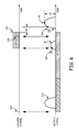
- FIG. 6 is a timing diagram illustrating an example technique for delivering atrio-synchronous ventricular pacing based on atrial contraction detection.
- FIG. 7 is a flow diagram of an example technique for delivering atrio-synchronous ventricular pacing based on atrial contraction detection that may be performed by a leadless pacing device implanted within a ventricle.
- FIG. 8 is a flow diagram illustrating an example technique for detecting an atrial contraction based on analysis of a motion signal that may be performed by a leadless pacing device implanted within a ventricle.
- FIG. 9 is a flow diagram illustrating an example technique for verifying efficacy of atrio-synchronous ventricular pacing based on atrial contraction detection that may be performed by a leadless pacing device implanted within a ventricle.
- FIG. 10 is a flow diagram illustrating an example technique for switching between an atrio-synchronous ventricular pacing mode and an asynchronous pacing mode that may be performed by a leadless pacing device implanted within a ventricle.
- FIG. 11 is a flow diagram illustrating an example technique for switching between atrio-synchronous ventricular pacing in response to atrial depolarizations and atrio-synchronous ventricular pacing in response to atrial contractions that may be performed by a leadless pacing device implanted within a ventricle.
- dual-chamber implantable pacemakers are implanted within a pocket within the patient's chest, and coupled to a right-atrial lead and a right-ventricular lead.
- the right-atrial lead extends from the implantable pacemaker in the pocket to the right atrium of the patient's heart, and positions one or more electrodes within the right atrium.
- the right-ventricular lead extends from the implantable pacemaker in the pocket to the right ventricle of the patient's heart, and positions one or more electrodes within the right ventricle.
- Such dual-chamber implantable pacemakers sense respective cardiac electrical activity, e.g., respective cardiac electrograms, via the one or more electrodes implanted within the right atrium and the one or more electrodes implanted within the right ventricle.
- dual-chamber implantable pacemakers detect intrinsic atrial depolarizations via the one or more electrodes implanted within the right atrium, and intrinsic ventricular depolarizations via the one or more electrodes implanted within the right ventricle.
- the implantable pacemakers may also deliver pacing pulses to the right atrium and the right ventricle via the one or more electrodes in the right atrium and the right ventricle, respectively.
- dual-chamber implantable pacemakers may be able to provide atrio-synchronous ventricular pacing.
- AV interval an intrinsic ventricular depolarization
- Such atrio-synchronous pacing in dual-chamber implantable pacemakers may be according to the VDD or DDD programming modes, which have been used to treat patients with various degrees of AV block.
- Implantable cardiac leads and the pocket in which pacemakers are implanted may be associated with complications.
- leadless pacing devices sized to be implanted entirely within one chamber, e.g., the right ventricle, of the heart have been proposed.
- Some proposed leadless pacemakers include a plurality of electrodes that are affixed to, or are a portion of, the housing of the leadless pacing device.
- Some proposed leadless pacing devices are capable of sensing intrinsic depolarizations of, and delivering pacing pulses to, the chamber of the heart in which they are implanted via the plurality of electrodes. However, because they are not coupled to electrodes in any other chamber, some proposed leadless pacing devices are incapable of sensing intrinsic depolarizations of, and delivering pacing pulses to, another chamber of the heart. Consequently, when implanted in the right ventricle, for example, such proposed leadless pacing devices may be unable to sense intrinsic atrial depolarizations of the atria, and may be limited to delivery of ventricular pacing according to an asynchronous ventricular pacing, e.g., according to a VVI or VVIR mode.
- FIG. 1 is a conceptual diagram illustrating an example leadless pacing system 10 A that comprises an example leadless pacing device (LPD) 12 A that is configured to deliver atrio-synchronous ventricular pacing based on atrial contraction detection.
- LPD 12 A is implanted within right ventricle 18 of heart 16 of patient 14 . More particularly, LPD 12 A is fixed or attached to the inner wall of the right ventricle 18 proximate to the apex of the right ventricle in the example of FIG. 1 .
- LPD 12 A may be fixed to the inner wall of right ventricle 18 at another location, e.g., on the intraventricular septum or free-wall of the right ventricle, or may be fixed to the outside of heart 16 , i.e., epicardially, proximate to right ventricle 18 . In other examples, LPD may be fixed within, on, or near the left-ventricle of heart 16 .
- LPD 12 A includes a plurality of electrodes that are affixed to, or are a portion of, the housing of LPD 12 A.
- LPD 12 A senses electrical signals associated with depolarization and repolarization of heart 16 , i.e., a cardiac electrogram signal, via the electrodes.
- LPD 12 A also delivers cardiac pacing pulses to right ventricle 18 via the electrodes.
- LPD 12 A detects depolarizations of right ventricle 18 within the cardiac electrogram. In some examples, LPD 12 A is not configured to detect intrinsic depolarizations of an atrium, e.g., right atrium 20 , or the atria of heart 16 generally, within the cardiac electrogram signal. In other examples, LPD 12 A is configured to detect atrial depolarizations within the cardiac electrogram signal.
- LDP 12 A is configured to detect atrial depolarizations with the cardiac electrogram signal, but may, at times, be unable to reliably detect atrial depolarizations, e.g., due to the quality of the cardiac electrogram signal, or the relatively small magnitude of the atrial depolarizations within a cardiac electrogram signal sensed via electrodes disposed within right ventricle 18 .
- LPD 12 A is configured to detect mechanical contractions of an atrium, e.g., right atrium 20 , or the atria of heart 16 generally, e.g., as an alternative to sensing electrical depolarizations of right atrium 20 . In this manner, LPD 12 A may be configured to deliver atrio-synchronous ventricular pacing to right ventricle 18 even when not configured, or unable, to detect atrial depolarizations.
- LPD 12 A includes a motion sensor configured to generate a motion signal as a function of movement of a heart of a patient.
- LPD 12 A is configured to identify an activation event of right ventricle 18 , and analyze the motion signal within an atrial contraction detection window that begins upon completion of an atrial contraction detection delay period that is initiated upon detection of the activation of the ventricle.
- the activation of the ventricle may be an intrinsic depolarization of the ventricle or delivery of a pacing pulse to the ventricle.
- LPD 12 A may be configured to detect contraction of right ventricle 18 based on the motion signal, and identify activation of the ventricle based on the detected ventricular contraction.
- LPD 12 A is configured to detect an atrial contraction based on the analysis of the motion signal within the atrial contraction detection window. If a subsequent intrinsic depolarization of right ventricle 18 is not detected, e.g., within an AV interval beginning when the atrial contraction was detected, LPD 12 A is further configured to deliver the pacing pulse to right ventricle 18 . In this manner, LPD 12 A is configured to deliver atrio-synchronous pacing to right ventricle 18 based on detection of atrial contractions.
- LPD 12 A is configured to assess the efficacy of the delivery of atrio-synchronous pacing to right ventricle 18 .
- LPD 12 A may detect a resulting contraction of right ventricle 18 based on the motion signal after delivery of a pacing pulse to the right ventricle, and determine whether the delivery of the pacing pulse to the right ventricle was effective based on the detection of the contraction of the right ventricle.
- LPD 12 A may determine one or more metrics of the ventricular contraction, such as a timing or amplitude of the ventricular contraction, and adjust the delivery of the ventricular pacing based on the one or more metrics.
- LPD 12 A may adjust the AV interval, which begins upon detection of atrial contraction, based on the one or more metrics, as one example.
- a motion signal generated by the motion sensor of LPD 12 A may include more general motion of patient 14 due to patient activity or experienced by patient, e.g., driving in a car. Such motion of patient 14 may interfere with the ability of LPD 12 A to detect atrial contractions.
- LPD 12 A is configured to determine an amount of motion of patient 14 based on the motion signal, and change from delivery of ventricular pacing according to an atrio-synchronous pacing mode to delivery of ventricular pacing according to an asynchronous pacing mode in response to determining that the amount of patient motion exceeds a threshold.
- LPD 12 A is additionally or alternatively configured to change from delivery of ventricular pacing according to an atrio-synchronous pacing mode to delivery of ventricular pacing according to an asynchronous pacing mode in response to determining that the heart rate is relatively high and/or irregular, e.g., based on intervals between successive intrinsic ventricular depolarizations and a stored threshold value, such as approximately 100 beats-per-minute (bpm).
- LPD 12 A is additionally or alternatively configured to change from delivery of ventricular pacing according to an atrio-synchronous pacing mode to delivery of ventricular pacing according to an asynchronous pacing mode in response to determining that an atrial contraction was not detected during a predetermined number of cardiac cycles.
- LPD 12 A delivers a ventricular pacing pulse if an intrinsic ventricular depolarization is not detected within a VV interval that begins when a previous intrinsic ventricular depolarization was detected, or a previous ventricular pacing pulse was delivered.
- leadless pacing system 10 A also includes a medical device programmer 22 , which is configured to program LPD 12 A and retrieve data from LPD 12 A.
- Programmer 22 may be a handheld computing device, desktop computing device, a networked computing device, or any other type of computing device, as examples.
- Programmer 22 may include a computer-readable storage medium having instructions that cause a processor of programmer 22 to provide the functions attributed to programmer 22 in the present disclosure.
- LPD 12 A may wirelessly communicate with programmer 22 .
- LPD 12 A may transfer data to programmer 22 and may receive data from programmer 22 .
- Programmer 22 may also wirelessly program and/or wirelessly charge LPD 12 A.
- Data retrieved from LPD 12 A using programmer 22 may include cardiac electrograms and motion signals stored by LPD 12 A that indicate the electrical and mechanical activity of heart 16 , and marker channel data that indicates the occurrence and timing of sensing, diagnosis, and therapy events associated with LPD 12 A, e.g., detection of atrial and ventricular depolarizations, atrial and ventricular contractions, and delivery of pacing pulses.
- Data transferred to LPD 12 A using programmer 22 may include, for example, operational programs for LPD 12 A that causes LPD 12 A to operate as described herein.
- data transferred to LPD 12 A using programmer 22 may include lengths of any AV intervals, atrial contraction detection delay periods, and atrial contraction detection windows described herein, any threshold values, such as for detecting atrial and/or ventricular contractions, or programming used by LPD 12 A to determine such values based on determined parameters of heart 16 , patient 14 , or LPD 12 A.
- FIG. 2 is a conceptual diagram further illustrating LPD 12 A.
- LPD 12 A includes an outer housing 30 , fixation times 32 A- 32 D (collectively “fixation tines 32 ”), and electrodes 34 and 36 .
- Outer housing 30 is configured to allow, e.g., has a size and form factor that allows, LPD 12 A to be entirely implanted within a chamber of heart 16 , such as right ventricle 18 .
- housing 30 may have a cylindrical (e.g., pill-shaped) form factor in some examples.
- Housing 30 may be hermetically sealed to prevent ingress of fluids into the interior of housing 30 .
- Fixation tines 32 extend from outer housing 30 , and are configured to engage with cardiac tissue to substantially fix a position of housing 30 within a chamber of heart 16 , e.g., at or near an apex of right ventricle 18 . Fixation tines 32 are configured to anchor housing 30 to the cardiac tissue such that LPD 12 A moves along with the cardiac tissue during cardiac contractions. Fixation tines 32 may be fabricated from any suitable material, such as a shape memory material (e.g., Nitinol). The number and configuration of fixation tines 32 illustrated in FIG. 2 is merely one example, and other numbers and configurations of fixation tines for anchoring an LPD housing to cardiac tissue are contemplated.
- a shape memory material e.g., Nitinol
- LPD 12 A includes a plurality of fixation tines 32 that are configured to anchor LPD 12 A to cardiac tissue in a chamber of a heart
- LPD 12 A may be fixed to cardiac tissue using other types of fixation mechanisms, such as, but not limited to, barbs, coils, and the like.
- LPD 12 A is configured to sense electrical activity of heart 16 , i.e., a cardiac electrogram, and deliver pacing pulses to right ventricle 18 , via electrodes 34 and 36 .
- Electrodes 34 and 36 may be mechanically connected to housing 30 , or may be defined by a portion of housing 30 that is electrically conductive. In either case, electrodes are electrically isolated from each other.
- Electrode 34 may be referred to as a tip electrode, and fixation tines 32 may be configured to anchor LPD 12 A to cardiac tissue such that electrode 34 maintains contact with the cardiac tissue.
- Electrode 36 may be defined by a conductive portion of housing 30 and, in some examples, may define at least part of a power source case that houses a power source (e.g., a battery) of LPD 12 A.
- a portion of housing 30 may be covered by, or formed from, an insulative material to isolate electrodes 34 and 36 from each other and/or to provide a desired size and shape for one or both of electrodes 34 and 36 .
- Outer housing 30 houses electronic components of LPD 12 A, e.g., an electrical sensing module for sensing cardiac electrical activity via electrodes 34 and 36 , a motion sensor, a mechanical sensing module for detecting cardiac contractions, and an electrical stimulation module for delivering pacing pulses via electrodes 34 and 36 .
- Electronic components may include any discrete and/or integrated electronic circuit components that implement analog and/or digital circuits capable of producing the functions attributed to an LPD described herein.
- housing 30 may house a memory that includes instructions that, when executed by one or more processors housed within housing 30 , cause LPD 12 A to perform various functions attributed to LPD 12 A herein.
- housing 30 may house a communication module that enables LPD 12 A to communicate with other electronic devices, such as medical device programmer 22 .
- housing 30 may house an antenna for wireless communication.
- Housing 30 may also house a power source, such as a battery.
- FIG. 3 is a conceptual diagram illustrating another example leadless pacing system 10 B that comprises another example LPD 12 B configured to deliver atrio-synchronous ventricular pacing based on atrial contraction detection.
- Leadless pacing system 10 B and LPD 12 B may be substantially the same as leadless pacing system 10 A and LPD 12 A described above with respect to FIGS. 1 and 2 .
- LPD 12 B includes a sensing extension 40 that includes an electrode 42 .
- sensing extension 40 may include one or more additional electrodes having the same polarity as electrode 42 .
- LPD 12 B may include an electrode 34 , but may not include electrode 36 , as described above with respect to LPD 12 A and FIG. 2 .
- Electrode 42 is electrically connected to electronics within a housing of LPD 12 B (e.g., an electrical sensing module and a stimulation module) via an electrical conductor of sensing extension 40 .
- the electrical conductor of sensing extension 40 is connected to the electronics via an electrically conductive portion of the housing of LPD 12 B, which may correspond to electrode 36 of LPD 12 A ( FIG. 2 ), but may be substantially completely insulated (e.g., completely electrically insulated or nearly completely electrically insulated). Substantially completely electrically insulating the conductive portion of the housing may allow an electrical sensing module of LPD 12 B to sense electrical cardiac activity with electrode 42 of sensing extension 40 , rather than the conductive portion of the housing.
- sensing extension 40 extends away from LPD 12 , which enables electrode 42 to be positioned relatively close to right atrium 20 .
- a cardiac electrogram sensed by LPD 12 B via electrodes 34 ( FIG. 2 ) and 42 may include a higher amplitude far-field atrial depolarization signal than a cardiac electrogram sensed by LPB 12 A via electrodes 34 and 36 ( FIG. 2 ).
- sensing extension 40 may facilitate detection of atrial depolarizations when LPD 12 B is implanted in right ventricle 18 .
- sensing extension 40 is sized to be entirely implanted within right ventricle 18 .
- sensing extension 40 is sized to extend into right atrium 20 .
- LPD 12 B is configured to detect atrial depolarizations within a cardiac electrogram signal. Accordingly, LPD 12 B may be configured to deliver atrio-synchronous ventricular pacing based on detection of atrial depolarizations. For example, LPD 12 B may be configured to deliver a pacing pulse to right ventricle 18 if an intrinsic depolarization of right ventricle 18 is not detected within an AV interval after detection of a depolarization of right atrium 20 .
- LPD 12 B may, at times, be unable to detect depolarizations of right atrium 20 , e.g., due to reduced cardiac electrogram signal quality.
- Reduced cardiac electrogram signal quality may include reduced amplitude of the atrial component of the cardiac electrogram signal and/or increased noise.
- Reduced cardiac electrogram signal quality may be caused by, for example, movement of sensing extension 40 relative to right atrium 20 , which may be caused by posture or activity of patient 14 , or other conditions of patient 14 , heart 16 , and/or LPD 12 B. Consequently, LPD 12 B is also configured to detect atrial contractions, and deliver atrio-synchronous ventricular pacing based on the atrial contractions, as described with respect to LPD 12 A.
- LPD 12 B is configured to determine that an atrial depolarization was not detected during a cardiac cycle. For example, LPD 12 B may be configured to determine that an atrial depolarization was not detected between consecutive ventricular depolarizations. In some examples, in response to determining that a depolarization of the atrium was not detected during a predetermined number of cardiac cycles, LPD 12 B is configured to switch from delivering atrio-synchronous ventricular pacing based on detection of atrial depolarization and using an electrical AV interval, to delivering atrio-synchronous ventricular pacing based on detection of atrial contractions and using a mechanical AV interval. Because mechanical contraction of the atrium occurs after electrical depolarization of the atrium, the mechanical AV interval may be shorter than the electrical AV interval.
- FIG. 4 is a functional block diagram illustrating an example configuration of an LPD 12 A to deliver atrio-synchronous ventricular pacing based on atrial contraction detection.
- LPD 12 B of FIG. 3 may have a similar configuration.
- electrode 36 of LPD 12 A may be replaced by electrode 42 of LPD 12 B, which may be positioned a greater distance away from electrode 34 and LPD 12 B, as described above with respect to FIG. 3 .
- LPD 12 A includes a processing module 50 , memory 52 , stimulation module 54 , electrical sensing module 56 , motion sensor 58 , mechanical sensing module 60 , communication module 62 , and power source 64 .
- Power source 64 may include a battery, e.g., a rechargeable or non-rechargeable battery.
- Modules included in LPD 12 A represent functionality that may be included in LPD 12 A of the present disclosure.
- Modules of the present disclosure may include any discrete and/or integrated electronic circuit components that implement analog and/or digital circuits capable of producing the functions attributed to the modules herein.
- the modules may include analog circuits, e.g., amplification circuits, filtering circuits, and/or other signal conditioning circuits.
- the modules may also include digital circuits, e.g., combinational or sequential logic circuits, memory devices, and the like.
- the functions attributed to the modules herein may be embodied as one or more processors, hardware, firmware, software, or any combination thereof.
- modules Depiction of different features as modules is intended to highlight different functional aspects, and does not necessarily imply that such modules must be realized by separate hardware or software components. Rather, functionality associated with one or more modules may be performed by separate hardware or software components, or integrated within common or separate hardware or software components.
- Processing module 50 may include any one or more of a microprocessor, a controller, a digital signal processor (DSP), an application specific integrated circuit (ASIC), a field-programmable gate array (FPGA), or equivalent discrete or integrated logic circuitry.
- processing module 50 includes multiple components, such as any combination of one or more microprocessors, one or more controllers, one or more DSPs, one or more ASICs, or one or more FPGAs, as well as other discrete or integrated logic circuitry. Additionally, although illustrated as separate functional components in FIG.
- stimulation module 54 electrical sensing module 56 , mechanical sensing module 60 , and communication module 62 may implemented in the one or more combination of one or more microprocessors, one or more controllers, one or more DSPs, one or more ASICs, one or more FPGAs, and/or other discrete or integrated logic circuitry that implements processing module 50 .
- Processing module 50 may communicate with memory 52 .
- Memory 52 may include computer-readable instructions that, when executed by processing module 50 , cause processing module 50 and any other modules of LPD 12 A to perform the various functions attributed to them herein.
- Memory 52 may include any volatile, non-volatile, magnetic, or electrical media, such as a random access memory (RAM), read-only memory (ROM), non-volatile RAM (NVRAM), electrically-erasable programmable ROM (EEPROM), Flash memory, or any other memory device.
- RAM random access memory
- ROM read-only memory
- NVRAM non-volatile RAM
- EEPROM electrically-erasable programmable ROM
- Flash memory or any other memory device.
- Stimulation module 54 and electrical sensing module 56 are electrically coupled to electrodes 34 , 36 .
- Processing module 50 is configured to control stimulation module 54 to generate and deliver pacing pulses to heart 16 (e.g., right ventricle 18 in the example shown in FIG. 1 ) via electrodes 34 , 36 .
- processing module 50 is configured to control electrical sensing module 56 monitor a signal from electrodes 34 , 36 in order to monitor electrical activity of heart 16 .
- Electrical sensing module 56 may include circuits that acquire an electrical signal from electrodes 34 , 36 , as well as circuits to filter, amplify, and otherwise process the electrical signal.
- the electrical signal includes intrinsic cardiac electrical activity, such as depolarizations and repolarizations of the ventricles and, in some cases, depolarizations of the atria, and may be referred to as a cardiac electrogram signal.
- Electrical sensing module 56 detects ventricular depolarizations within the cardiac electrogram signal and, in some examples, detects atrial depolarizations within the cardiac electrogram signal.
- LPD 12 A also includes motion sensor 58 .
- motion sensor 58 comprises one or more accelerometers.
- motion sensor 58 comprises a plurality of accelerometers, e.g., three accelerometers, each of which is oriented to detect motion in the direction of a respective axis or vector. The axes or vectors may be orthogonal.
- motion sensor 58 may comprises one or more different sensors that generate a signal as a function of motion, instead of or in addition to the one or more accelerometers, such as gyros, mercury switches, or bonded piezoelectric crystals.
- Mechanical sensing module 60 includes circuitry to receive the motion signal from motion sensor 58 , as well as circuits to filter, amplify, and otherwise process the motion signal. Because LPD 12 A is affixed to heart 16 , motion sensor 60 generates a motion signal that varies as a function of motion of the heart, including motion associated with the contraction of the atria, and motion associated with the subsequent contraction of the ventricles. Because LPD 12 A is implanted within patient 14 , the motion signal generated by motion sensor 58 also varies as a function of any motion of (or experienced by) the patient, e.g., due to patient activity.
- mechanical sensing module 60 analyzes the motion signal generated by motion sensor 58 to detect contraction of an atrium.
- Mechanical sensing module 60 may also analyze the motion signal to detect ventricular contraction.
- mechanical sensing module 60 may filter the motion signal to exclude components other than cardiac motion, e.g., components of the motion signal associated with motion engaged in or experienced by patient 14 .
- mechanical sensing module 60 may high-pass filter the motion signal, e.g., to exclude frequencies lower than about 40 Hz.
- mechanical sensing module 60 may high-pass filter the motion signal, e.g., to exclude frequencies lower than about 60 Hz.
- Mechanical sensing module 60 may also analyze the motion signal to detect other parameters of patient 14 , such as patient activity level. To detect patient activity level, mechanical sensing module 60 may filter the motion signal to exclude components other than those resulting from patient activity, such as components associated with cardiac contraction. For example, mechanical sensing module 60 may low-pass filter the motion signal generated by motion sensor 58 , e.g., to exclude frequencies above about 40 Hz. Processing module 50 may control stimulation module 54 to deliver rate responsive ventricular pacing based on the activity level determined by motion sensing module 60 . For example, processing module 50 may adjust an AV interval based on the activity level.
- a motion signal generated by motion sensor 58 may include one or more of the signals generated by the sensors, respectively, or a combination of one or more of the respective signals, which may be referred to as component signals of the motion signal.
- Mechanical sensing module 60 may derive the motion signal based on one or more of the component signals according to a sensing vector, where different sensing vectors specify a different one or more of the component signals. In some examples, mechanical sensing module 60 is configured to derive the motion signal according to a variety of different sensing vectors.
- mechanical sensing module 60 may be configured to sense different parameters or events, e.g., atrial contractions, ventricular contractions, and patient activity, using different sensing vectors.
- mechanical sensing module 60 is configured to detect an event or parameter, e.g., atrial contraction, according to a plurality of sensing vectors, and identify one or more sensing vectors that provide adequate detection of the event.
- Communication module 62 may include any suitable hardware (e.g., an antenna), firmware, software, or any combination thereof for communicating with another device, such as programmer 22 ( FIGS. 1 and 3 ) or a patient monitor. Under the control of processing module 50 , communication module 62 may receive downlink telemetry from and send uplink telemetry to other devices, such as programmer 22 or a patient monitor, with the aid of an antenna included in communication module 62 .
- suitable hardware e.g., an antenna
- firmware e.g., software
- Communication module 62 may receive downlink telemetry from and send uplink telemetry to other devices, such as programmer 22 or a patient monitor, with the aid of an antenna included in communication module 62 .
- Memory 52 may include data recorded by LPD 12 A, e.g., cardiac electrograms, motion signals, heart rates, information regarding detection of atrial contractions, ventricular pacing efficacy, etc. Under the direction of processing module 50 , communication module 62 may transfer data recorded by LDP 12 A to another device, such as programmer 22 . Memory 52 may also store programming data received by processing module 50 from another device, such as programmer 22 , via communication module 62 . The programming data stored in memory 52 may include, as examples, lengths of any AV intervals, atrial contraction detection delay periods, and atrial contraction detection windows described herein.
- the programming data stored in memory 52 may additionally or alternatively include any threshold values described herein, such as for detecting atrial and/or ventricular contractions, determining whether pacing is efficacious, or determining whether atrio-synchronous ventricular pacing should by suspended in favor of asynchronous pacing.
- the programming data stored in memory 52 may additionally or alternatively include data used by processing module 50 to determine any values described herein, e.g., based determined parameters of heart 16 , patient 14 , or LPD 12 A.
- FIG. 5 is a graph illustrating a cardiac electrogram signal 70 and a corresponding motion signal 72 generated by one or more accelerometers.
- Cardiac electrogram signal 70 includes ventricular depolarizations (R-waves) 74 A and 74 B, and corresponding ventricular repolarizations (T-waves) 76 A and 76 B.
- a cardiac cycle 78 may be defined as the period from one ventricular depolarization 74 A to the next ventricular depolarization 74 B, or the period between any repeating fiducial features of cardiac electrogram signal 70 or motion signal 72 .
- cardiac cycle 78 includes an ejection phase, which may also be referred to as systole.
- a ventricular contraction 80 A occurs as a result of ventricular depolarization 74 A.
- the S1 and S2 heart sounds which are associated with ventricular contraction, occur at the beginning and end, respectively, of the ejection phase.
- the S1 and S2 heart sounds are produced by closing of the atrioventricular values and semilunar valves of heart 16 , respectively.
- cardiac cycle 78 includes a passive filing stage during diastole, during which passive filling of the ventricles may produce the S3 heart sound. Additionally, near the end of diastole, an atrial contraction 82 occurs, actively filling of the ventricles. The active filing of the ventricles may produce the S4 heart sound. The atrial depolarization that resulted in atrial contraction 82 is not present in cardiac electrogram 70 . Another cardiac cycle begins with ventricular depolarization 74 B, and the resulting ventricular contraction 80 B.
- Mechanical sensing module 60 detects atrial contractions, and may also detect ventricular contractions, based on an analysis of a motion signal generated by motion sensor 58 .
- the motion signal generated by motion sensor 58 may vary based on the movement of tissue of heart 16 , as well as any associated mechanical perturbations or vibrations, during contraction of heart 16 .
- Mechanical perturbations or vibrations may include those associated with the S1-S4 hearts sounds discussed above.
- mechanical sensing module 60 may detect an atrial contraction based on features in motion signal 72 that are indicative of movement of cardiac tissue during atrial contraction, and/or the presence of mechanical perturbations associated with the S4 heart sound.
- mechanical sensing module 60 may detect a ventricular contraction based on features in motion signal 72 that are indicative of movement of cardiac tissue during ventricular contraction, and/or the presence of mechanical perturbations associated with the S1 heart sound.
- FIG. 6 is a timing diagram illustrating an example technique for delivering atrio-synchronous ventricular pacing based on atrial contraction detection.
- the timing diagram of FIG. 6 includes a ventricular marker channel, and a corresponding motion signal.
- mechanical sensing module 60 identifies an activation of a ventricle, e.g., right ventricle 18 .
- An activation of a ventricle may be an intrinsic or paced depolarization of the ventricle, or a mechanical contraction of the ventricle.
- Mechanical sensing module 60 may identify activation of a ventricle by determining that electrical sensing module 56 detected an intrinsic depolarization 90 A of the ventricle, by determining that stimulation module 54 delivered a pacing pulse to the ventricle, or by detecting mechanical contraction 92 A of ventricle.
- mechanical sensing module 60 waits for an atrial contraction detection delay period 94 , and then analyzes the motion signal generated by motion sensor 58 within an atrial contraction detection window 96 that begins the atrial contraction detection delay period 94 after the activation of the ventricle, i.e., that begins upon completion of the atrial contraction detection delay period 94 .
- mechanical sensing module 60 determined that electrical sensing module detected ventricular depolarization 90 A, and analyzes the motion signal within atrial contraction detection window 96 that begins atrial contraction detection delay period 94 after detection of ventricular depolarization 90 A.
- Atrial contraction delay period 94 may allow mechanical sensing module 60 to avoid misidentifying ventricular contraction 92 A, or other motion of heart during the cardiac cycle prior to atrial depolarization and contraction, as an atrial contraction.
- atrial contraction delay period 94 is at least approximately 300 milliseconds.
- atrial contraction delay period 94 is at least approximately 400 milliseconds, or is approximately 400 milliseconds.
- atrial contraction detection delay period 94 is at least approximately 600 milliseconds.
- processing module 50 and/or mechanical sensing module 60 adjusts atrial contraction detection delay period 94 based on a heart rate of patient 14 , e.g., based on one or more intervals between consecutive intrinsic ventricular depolarizations detected by electrical sensing module 56 .
- processing module 50 and/or mechanical sensing module 60 may increase atrial contraction detection delay period 94 as heart rate decreases, and decrease atrial contraction detection delay period 94 as heart rate increases.
- a clinician or other user may program a length of atrial contraction delay period 94 , e.g., using programmer 22 . The user may select the length of atrial contraction delay period 94 based on individual patient characteristics.
- mechanical sensing module 60 may detect atrial contraction 98 .
- Mechanical sensing module 60 may extend atrial contraction detection window 96 , and the associated analysis of the motion signal, until detection of atrial contraction 98 , or until a subsequent intrinsic ventricular depolarization 90 B is detected by electrical sensing module 56 , or a subsequent ventricular pacing pulse 104 is delivered by stimulation module 54 .
- mechanical sensing module 60 filters the motion signal within atrial contraction detection window 96 .
- Mechanical sensing module 60 may also rectify the motion signal within atrial contraction detection window 96 .
- mechanical sensing module 60 detects atrial contraction 98 by comparing an amplitude of the motion signal within atrial contraction detection window 96 to a threshold 100 .
- mechanical sensing module 60 determines a derivative signal of the motion signal, e.g., the filtered and/or rectified motion signal, and compares an amplitude of the derivative signal, which represents the rate of change of the motion signal, to threshold 100 .
- mechanical sensing module 60 detects the time of atrial contraction 98 as the earliest time point at which the amplitude of the motion signal, or it derivative signal, exceeds threshold 100 .
- threshold 100 is a constant value, which may be determined by a manufacturer of an LPD 12 A, or programmed by a clinician using programmer 22 .
- mechanical sensing module 60 and/or processing module 50 determines threshold 100 based on a peak amplitude of the motion signal during one or more previously detected atrial contractions. For example, mechanical sensing module 60 and/or processing module 50 may determine that threshold 100 is a value within a range from approximately 20 percent to approximately 80 percent, such as approximately 50 percent, of the peak amplitude of the motion signal during the most recently detected atrial contraction, or of an average peak amplitude of the motion signal during a plurality of previously detected atrial contractions.
- mechanical sensing module 60 may detect atrial contraction 98 using morphological comparison techniques. For example, mechanical sensing module 60 may compare the motion signal within atrial contraction detection window 96 to one or more templates representing one or more features of a motion signal during atrial contraction. Mechanical sensing module 60 may detect atrial contraction 98 at the point when a statistic resulting from the comparison indicates a sufficient level of similarity between the motion signal and the one or more templates.
- processing module 50 determines whether electrical sensing module 56 detects an intrinsic ventricular depolarization 90 B resulting from the atrial depolarization that led to atrial contraction 98 . For example, processing module 50 may determine whether electrical sensing module 56 detects intrinsic ventricular depolarization 90 B within an AV interval 102 that begins upon detection of atrial contraction 98 by mechanical sensing module 60 . If electrical sensing module 56 does not detect intrinsic depolarization 90 B within AV interval 102 , e.g., because it did not occur due to AV nodal block, then processing module 50 controls electrical stimulation module 54 to generate and deliver ventricular pacing pulse 104 at the expiration of AV interval 102 . In this manner, LPD 12 A delivers atrio-synchronous ventricular pacing based on detection of atrial contractions.
- AV interval 102 which may be referred to as a mechanical AV interval, may be shorter than an (electrical) AV interval employed by a pacemaker that provides atrio-synchronous ventricular pacing based on detection of atrial depolarizations.
- AV interval 102 is less than approximately 100 milliseconds.
- AV interval 102 is less than approximately 50 milliseconds.
- AV interval 102 is approximately 30 milliseconds.
- mechanical AV interval 102 is approximately 20 to 30 milliseconds shorter than an electrical AV interval for the patient.
- processing module 50 does not employ an AV interval.
- processing module determines whether electrical sensing module 56 has detected intrinsic ventricular depolarization 90 B. If electrical sensing module 56 has not detected intrinsic ventricular depolarization 90 B, then processing module 50 controls stimulation module 54 to generate and deliver a ventricular pacing pulse.
- LPD 12 A determines whether the delivery of ventricular pacing pulse 104 was effective based on detection of the ventricular contraction 92 B resulting from the delivery of pacing pulse 104 .
- mechanical sensing module 60 detects ventricular contraction 92 B based on the motion signal, e.g., based on a comparison of the motion signal to a threshold 106 in a manner similar to that employed for detection of atrial contraction 98 based on threshold 100 , or based on a morphological analysis.
- mechanical sensing module 60 detects the time of ventricular contraction 110 to be the first time-point after delivery of pacing pulse 104 when the amplitude of the motion signal exceeds threshold 106 .
- Mechanical sensing module 60 and/or processing module 50 may determine an interval 108 from delivery of pacing pulse 104 to a time of detection of ventricular contraction 92 B. Mechanical sensing module 60 may also determine a peak amplitude 110 of the motion signal during ventricular contraction 92 B.
- processing module 50 adjusts AV interval 102 based on the determination of whether the delivery of pacing pulse 104 to the ventricle was effective. For example, processing module 50 may decrease AV interval 102 in response to determining that interval 108 is less than a threshold. Additionally or alternatively, processing module 50 may increase AV interval 102 in response to determining that peak amplitude 110 is greater than a threshold.
- FIG. 7 is a flow diagram of an example technique for delivering atrio-synchronous ventricular pacing based on atrial contraction detection that may be performed by a LPD implanted within a ventricle, such as LPD 12 A or LPD 12 B implanted within right ventricle 18 of heart 16 .
- the example technique of FIG. 7 may be performed, at least in part, by a processing module 50 of such an LPD.
- the LPD identifies ventricular activation ( 120 ), and detects a subsequent atrial contraction based on a motion signal generated by a motion sensor of the LPD ( 122 ).
- the LPD determines whether an intrinsic ventricular depolarization resulting from the atrial depolarization that caused the detected atrial contraction has been detected, e.g., within an AV interval beginning upon detection of the atrial contraction ( 124 ).
- the LPD detects an intrinsic ventricular depolarization resulting from the atrial depolarization that caused the detected atrial contraction (YES of 124 ), then the LPD identifies the intrinsic ventricular depolarization as a ventricular activation that begins the next cardiac cycle ( 120 ). If the LPD does not detect an intrinsic ventricular depolarization resulting from the atrial depolarization that caused the detected atrial contraction (NO of 124 ), then the LPD delivers a ventricular pacing pulse ( 126 ). For example, the LPD may deliver a ventricular pacing pulse upon expiration of the AV interval without detecting an intrinsic ventricular depolarization. The LPD identifies delivery of the ventricular pacing pulse as a ventricular activation that begins the next cardiac cycle ( 120 ). The LPD may also determine whether the delivery of the cardiac pacing pulse was effective, e.g., as described above with respect to FIG. 6 ( 128 ).
- FIG. 8 is a flow diagram illustrating an example technique for detecting an atrial contraction based on analysis of a motion signal (e.g., 122 of FIG. 7 ) that may be performed by a LPD implanted within a ventricle, such as LPD 12 A or LPD 12 B implanted within right ventricle 18 of heart 16 .
- the example technique of FIG. 8 may be performed, at least in part, by a processing module 50 of such an LPD.
- the LPD begins an atrial contraction detection delay period upon identification of a ventricular activation event ( 130 ).
- the LPD begins an atrial contraction detection window upon expiration of the atrial contraction delay period ( 132 ).
- the LPD analyzes the motion signal generated by the motion sensor of the LPD within the atrial contraction detection window.
- the LPD filters the motion signal within the atrial contraction detection window, rectifies the filtered signal, and generates a derivative signal of the filtered and rectified motion signal within the atrial contraction detection window ( 134 ).
- the LPD determines whether an amplitude of the derivative signal within the atrial contraction detection window exceeds a threshold ( 136 ). In response to determining that the amplitude of the derivative signal within the atrial contraction detection window exceeds the threshold (YES of 136 ), the LPD detects an atrial contraction ( 138 ).
- FIG. 9 is a flow diagram illustrating an example technique for verifying efficacy of atrio-synchronous ventricular pacing based on atrial contraction detection that may be performed by a LPD implanted within a ventricle, such as LPD 12 A or LPD 12 B implanted within right ventricle 18 of heart 16 .
- the LPD detects a ventricular contraction resulting from a ventricular pacing pulse based on the motion signal generated by a motion sensor of the LPD after delivery of the ventricular pacing pulse ( 140 ).
- the LPD may detect a time of the ventricular contraction as a time when an amplitude of the motion signal, e.g., an amplitude of a derivative signal generated from a filtered and rectified motion signal, exceeds a threshold.
- the LPD determines an interval from the delivery of the ventricular pacing pulse to the time of detection of the ventricular contraction ( 142 ). The LPD determines whether the interval is less than a threshold ( 144 ). If the interval is less than the threshold (YES of 144 ), then the LPD decreases an AV interval used for delivery of atrio-synchronous ventricular pacing pulses after detection of an atrial contraction ( 146 ).
- the LPD determines a peak amplitude of the motion signal during the detected ventricular contraction ( 148 ). The LPD determines whether the peak amplitude of the motion signal during the detected ventricular contraction is greater than a threshold ( 150 ). If the peak amplitude is greater than the threshold (YES of 150 ), then the LPD increases an AV interval used for delivery of atrio-synchronous ventricular pacing pulses after detection of an atrial contraction ( 152 ). If the peak amplitude is not greater than the threshold, e.g., is less than the threshold (NO of 150 ), then the LPD maintains the AV interval at its current value ( 154 ).
- FIG. 10 is a flow diagram illustrating an example technique for switching between an atrio-synchronous ventricular pacing mode and an asynchronous pacing mode that may be performed by a LPD implanted within a ventricle, such as LPD 12 A or LPD 12 B implanted within right ventricle 18 .
- the example technique of FIG. 10 may be performed, at least in part, by a processing module 50 of such an LPD.
- the LPD operates in an atrio-synchronous ventricular pacing mode in which the LPD delivers atrio-synchronous ventricular pacing based detection of atrial contractions, as described herein ( 160 ).
- the atrio-synchronous ventricular pacing mode in which the LPD delivers atrio-synchronous ventricular pacing based detection of atrial contractions may be similar to a conventional VDD pacing mode, and may be referred to as a VDD pacing mode.
- the LPD determines whether a patient activity level, or a level of motion experienced by the patient, exceeds a threshold ( 162 ).
- the LPD may determine the patient activity or motion level based on the motion signal generated by the motion sensor of the LPD. If the activity or motion level exceeds the threshold (YES of 162 ), then the LPD switches to an asynchronous ventricular pacing mode ( 164 ).
- the LDP may deliver pacing pulses to the ventricle if an intrinsic ventricular depolarization is not detected within a VV interval from the last paced or intrinsic ventricular depolarization.
- the asynchronous ventricular pacing mode of the LPD may be similar to a conventional VVI or VVIR pacing mode, and may be referred to as a WI or VVIR pacing mode.
- the LPD determines whether the heart rate is greater than a threshold, e.g., greater than approximately 80 beats-per-minute or approximately 100 beats-per-minute, and/or irregular ( 166 ).
- the LPD may determine the heart rate and its regularity based on intervals between previous ventricular depolarizations. If the heart rate is greater than the threshold and/or irregular (YES of 166 ), then the LPD switches to the asynchronous ventricular pacing mode ( 164 ).
- the LPD determines whether it is able to detect atrial contractions based on an analysis of the motion signal generated by a motion sensor of the LPD ( 168 ). For example, the LPD may determine that it is unable to detect atrial contractions if it determines that it has not detected atrial contractions for a predetermined number of cardiac cycles.
- the predetermined number of cardiac cycles may be any number of one or more cardiac cycles, which may be consecutive or non-consecutive. For example, the predetermined number of cardiac cycles may be three.
- LPD determines that it is unable to detect atrial contraction (NO of 168 )
- the LPD switches to the asynchronous ventricular pacing mode ( 170 ).
- the LPD may also change a motion signal sensing vector according to which the LPD derives the motion signal from one or more of a plurality of signals generated by the motion sensor, e.g., the plurality accelerometers of the motion sensor ( 172 ).
- LPD may continue to deliver ventricular pacing according to the atrio-synchronous ventricular pacing mode ( 160 ). Further, after delivering pacing according to the asynchronous pacing mode ( 164 , 170 ) for a period of time, or until a condition that led to the switch to the asynchronous mode has abated, the LPD may switch to delivery of ventricular pacing according to the atrio-synchronous ventricular pacing mode.
- FIG. 11 is a flow diagram illustrating an example technique for switching between atrio-synchronous ventricular pacing in response to atrial depolarizations and atrio-synchronous ventricular pacing in response to atrial contractions that may be performed by a LPD implanted within a ventricle, such as right ventricle 18 , that is able to detect depolarizations of an atrium, such as right atrium 20 .
- LPD 12 B that is coupled to sensing extension 40 is one example of such an LPD, although LPD 12 A may also be configured to detect depolarizations of the atrium.
- the example technique of FIG. 11 may be performed by a processing module 50 of such an LPD.
- the LPD delivers atrio-synchronous pacing a first, electrical AV interval after detection of atrial depolarizations ( 180 ).
- the LPD determines whether it is unable to detect atrial depolarizations ( 182 ).
- the LPD may determine that it is unable to detect atrial depolarizations if it determines that it has not detected atrial depolarizations for a predetermined number of cardiac cycles, e.g., has not detected an atrial depolarization between consecutive ventricular depolarizations of a predetermined number of cardiac cycles.
- the predetermined number of cardiac cycles may be any number of one or more cardiac cycles, which may be consecutive or non-consecutive.
- LPD may activate atrial contraction detection, and switch to delivery of atrio-synchronous pacing a second, mechanical AV interval after detection of atrial contractions ( 184 ). If LPD determines that it is able to detect atrial depolarizations (NO of 182 ), or some time delivering atrio-synchronous ventricular pacing based on atrial contraction detection ( 184 ), then the LPD may continue or switch back to delivery of atrio-synchronous ventricular pacing based on atrial depolarization detection ( 180 ).
- processors including one or more microprocessors, DSPs, ASICs, FPGAs, or any other equivalent integrated or discrete logic circuitry, as well as any combinations of such components, embodied in programmers, such as physician or patient programmers, stimulators, image processing devices or other devices.
- processors including one or more microprocessors, DSPs, ASICs, FPGAs, or any other equivalent integrated or discrete logic circuitry, as well as any combinations of such components, embodied in programmers, such as physician or patient programmers, stimulators, image processing devices or other devices.
- processor or “processing circuitry” may generally refer to any of the foregoing logic circuitry, alone or in combination with other logic circuitry, or any other equivalent circuitry.
- Such hardware, software, firmware may be implemented within the same device or within separate devices to support the various operations and functions described in this disclosure.
- any of the described units, modules or components may be implemented together or separately as discrete but interoperable logic devices. Depiction of different features as modules or units is intended to highlight different functional aspects and does not necessarily imply that such modules or units must be realized by separate hardware or software components. Rather, functionality associated with one or more modules or units may be performed by separate hardware or software components, or integrated within common or separate hardware or software components.
- the functionality ascribed to the systems, devices and techniques described in this disclosure may be embodied as instructions on a computer-readable medium such as RAM, ROM, NVRAM, EEPROM, FLASH memory, magnetic data storage media, optical data storage media, or the like.
- the instructions may be executed to support one or more aspects of the functionality described in this disclosure.
Abstract
A leadless pacing device (LPD) includes a motion sensor configured to generate a motion signal as a function of heart movement. The LPD is configured to analyze the motion signal within an atrial contraction detection window that begins an atrial contraction detection delay period after activation of the ventricle, and detect a contraction of an atrium of the heart based on the analysis of the motion signal within the atrial contraction detection window. If the LPD does not detect a ventricular depolarization subsequent to the atrial contraction, e.g., with an atrio-ventricular (AV) interval beginning when the atrial contraction was detected, the LPD delivers a ventricular pacing pulse.
Description
This application claims the benefit of U.S. Provisional Application No. 62/028,957, filed Jul. 25, 2014, the entire contents of which are incorporated herein by reference.
The disclosure relates to cardiac pacing, and more particularly, to cardiac pacing using a leadless pacing device.
An implantable pacemaker may deliver pacing pulses to a patient's heart and monitor conditions of the patient's heart. In some examples, the implantable pacemaker comprises a pulse generator and one or more electrical leads. The pulse generator may, for example, be implanted in a small pocket in the patient's chest. The electrical leads may be coupled to the pulse generator, which may contain circuitry that generates pacing pulses and/or senses cardiac electrical activity. The electrical leads may extend from the pulse generator to a target site (e.g., an atrium and/or a ventricle) such that electrodes at the distal ends of the electrical leads are positioned at a target site. The pulse generator may provide electrical stimulation to the target site and/or monitor cardiac electrical activity at the target site via the electrodes.
A leadless pacing device has also been proposed for sensing electrical activity and/or delivering therapeutic electrical signals to the heart. The leadless pacing device may include one or more electrodes on its outer housing to deliver therapeutic electrical signals and/or sense intrinsic depolarizations of the heart. The leadless pacing device may be positioned within or outside of the heart and, in some examples, may be anchored to a wall of the heart via a fixation mechanism.
The disclosure describes a leadless pacing device (hereinafter, “LPD”) that is configured for implantation in a ventricle of a heart of a patient, and is configured to deliver atrio-synchronous ventricular pacing based on detection of atrial contraction. More particularly, the LPD includes a motion sensor configured to generate a motion signal as a function of heart movement. The motion sensor may include one or more accelerometers, which may have a single axis, or multiple axes. The LPD is configured to analyze the motion signal within an atrial contraction detection window. The atrial contraction detection window begins upon completion of an atrial contraction detection delay period, which begins upon detection of activation of the ventricle. The LPD is configured to detect a contraction of an atrium of the heart based on the analysis of the motion signal within the atrial contraction detection window. If the LPD does not detect a ventricular depolarization subsequent to the atrial contraction, e.g., within an atrioventricular (AV) interval beginning when the atrial contraction was detected, the LPD delivers a ventricular pacing pulse. In some examples, the LPD is configured to deliver atrio-synchronous ventricular pacing using an electrical AV interval based on detection of atrial depolarizations via a plurality of electrodes of the LPD and, if the LPD is unable to detect atrial depolarizations, switch to delivering atrio-synchronous ventricular pacing using a mechanical AV interval, which may be shorter than the electrical AV interval, based on detection of atrial contractions.
In one example, a leadless pacing device is configured to provide atrio-synchronous ventricular pacing. The leadless pacing device comprises a plurality of electrodes, a motion sensor configured to generate a motion signal as a function of movement of a heart of a patient, a stimulation module coupled to the plurality of electrodes, wherein the stimulation module is configured to generate pacing pulses and deliver the pacing pulses to a ventricle of the heart via the plurality of electrodes, and an electrical sensing module coupled to the plurality of electrodes, wherein the electrical sensing module is configured to detect depolarizations of the ventricle within a cardiac electrogram sensed via the plurality of electrodes. The leadless pacing device further comprises a mechanical sensing module coupled to the motion sensor. The mechanical sensing module is configured to receive the motion signal from the motion sensor, identify an activation of the ventricle and, upon identification of the activation of the ventricle, initiate an atrial contraction detection delay period. The mechanical sensing module is further configured to analyze the motion signal within an atrial contraction detection window that begins upon completion of the atrial contraction detection delay period, and detect a contraction of an atrium of the heart based on the analysis of the motion signal within the atrial contraction detection window. The leadless pacing device further comprises a processing module configured to control the stimulation module to generate a pacing pulse and deliver the pacing pulse to the ventricle via the plurality of electrodes in response to the detection of the contraction of the atrium by the mechanical sensing module. The leadless pacing device further comprises a housing configured to be implanted within the ventricle, wherein the housing encloses the motion sensor, the stimulation module, the electrical sensing module, the mechanical sensing module, and the processing module.
In another example, a method for providing atrio-synchronous ventricular pacing by a leadless pacing device implanted within a ventricle of a heart of a patient comprises identifying an activation of the ventricle, upon identification of the activation of the ventricle, initiating an atrial contraction detection delay period, and analyzing a motion signal within an atrial contraction detection window that begins upon completion of the atrial contraction detection delay period. The motion signal is generated by a motion sensor of the leadless pacing device as a function of movement of the heart. The method further comprises detecting a contraction of an atrium of the heart based on the analysis of the motion signal within the atrial contraction detection window, and delivering a pacing pulse to the ventricle in response to the detection of the contraction of the atrium.
In another example, a leadless pacing device is configured to provide atrio-synchronous ventricular pacing. The leadless pacing device comprises means for generating a motion signal as a function of movement of a heart of a patient, means for identifying an activation of a ventricle of the heart, means for initiating an atrial contraction detection delay period upon identification of the activation of the ventricle, and means for analyzing the motion signal within an atrial contraction detection window that begins upon completion of the atrial contraction detection delay period. The leadless pacing device further comprises means for detecting a contraction of an atrium of the heart based on the analysis of the motion signal within the atrial contraction detection window, and means for delivering a pacing pulse to the ventricle in response to the detection of the contraction of the atrium.
In another example, a computer-readable storage medium comprises instructions stored thereon that, when executed by one or more programmable processors of a leadless pacing device configured to provide atrio-synchronous ventricular pacing, cause the one or more processors to identify an activation of the ventricle, upon identification of the activation of the ventricle, initiate an atrial contraction detection delay period, and analyze a motion signal within an atrial contraction detection window that begins upon completion of the atrial contraction detection delay period. The motion signal is generated by a motion sensor of the leadless pacing device as a function of movement of the heart. The instructions further cause the one or more processors to detect a contraction of an atrium of the heart based on the analysis of the motion signal within the atrial contraction detection window, and control delivery of a pacing pulse to the ventricle in response to the detection of the contraction of the atrium.
The details of one or more examples are set forth in the accompanying drawings and the description below. Other features, objects, and advantages will be apparent from the description and drawings, and from the claims.
Typically, dual-chamber implantable pacemakers are implanted within a pocket within the patient's chest, and coupled to a right-atrial lead and a right-ventricular lead. The right-atrial lead extends from the implantable pacemaker in the pocket to the right atrium of the patient's heart, and positions one or more electrodes within the right atrium. The right-ventricular lead extends from the implantable pacemaker in the pocket to the right ventricle of the patient's heart, and positions one or more electrodes within the right ventricle.
Such dual-chamber implantable pacemakers sense respective cardiac electrical activity, e.g., respective cardiac electrograms, via the one or more electrodes implanted within the right atrium and the one or more electrodes implanted within the right ventricle. In particular, such dual-chamber implantable pacemakers detect intrinsic atrial depolarizations via the one or more electrodes implanted within the right atrium, and intrinsic ventricular depolarizations via the one or more electrodes implanted within the right ventricle. The implantable pacemakers may also deliver pacing pulses to the right atrium and the right ventricle via the one or more electrodes in the right atrium and the right ventricle, respectively. Due to the ability to sense both atrial and ventricular electrical activity, such dual-chamber implantable pacemakers may be able to provide atrio-synchronous ventricular pacing. For patients with intermittent AV node conduction, it may be preferable to inhibit ventricular pacing and allow an intrinsic ventricular depolarization to occur for a time, referred to as the AV interval, after an intrinsic atrial depolarization or atrial pace. Such atrio-synchronous pacing in dual-chamber implantable pacemakers may be according to the VDD or DDD programming modes, which have been used to treat patients with various degrees of AV block.
Implantable cardiac leads and the pocket in which pacemakers are implanted may be associated with complications. To avoid such complications leadless pacing devices sized to be implanted entirely within one chamber, e.g., the right ventricle, of the heart have been proposed. Some proposed leadless pacemakers include a plurality of electrodes that are affixed to, or are a portion of, the housing of the leadless pacing device.
Some proposed leadless pacing devices are capable of sensing intrinsic depolarizations of, and delivering pacing pulses to, the chamber of the heart in which they are implanted via the plurality of electrodes. However, because they are not coupled to electrodes in any other chamber, some proposed leadless pacing devices are incapable of sensing intrinsic depolarizations of, and delivering pacing pulses to, another chamber of the heart. Consequently, when implanted in the right ventricle, for example, such proposed leadless pacing devices may be unable to sense intrinsic atrial depolarizations of the atria, and may be limited to delivery of ventricular pacing according to an asynchronous ventricular pacing, e.g., according to a VVI or VVIR mode.
As described in greater detail below, LPD 12A includes a motion sensor configured to generate a motion signal as a function of movement of a heart of a patient. LPD 12A is configured to identify an activation event of right ventricle 18, and analyze the motion signal within an atrial contraction detection window that begins upon completion of an atrial contraction detection delay period that is initiated upon detection of the activation of the ventricle. The activation of the ventricle may be an intrinsic depolarization of the ventricle or delivery of a pacing pulse to the ventricle. In some examples, LPD 12A may be configured to detect contraction of right ventricle 18 based on the motion signal, and identify activation of the ventricle based on the detected ventricular contraction.
In some examples, LPD 12A is configured to assess the efficacy of the delivery of atrio-synchronous pacing to right ventricle 18. For example, LPD 12A may detect a resulting contraction of right ventricle 18 based on the motion signal after delivery of a pacing pulse to the right ventricle, and determine whether the delivery of the pacing pulse to the right ventricle was effective based on the detection of the contraction of the right ventricle. In some examples, LPD 12A may determine one or more metrics of the ventricular contraction, such as a timing or amplitude of the ventricular contraction, and adjust the delivery of the ventricular pacing based on the one or more metrics. LPD 12A may adjust the AV interval, which begins upon detection of atrial contraction, based on the one or more metrics, as one example.
In addition to the motion of the heart, a motion signal generated by the motion sensor of LPD 12A may include more general motion of patient 14 due to patient activity or experienced by patient, e.g., driving in a car. Such motion of patient 14 may interfere with the ability of LPD 12A to detect atrial contractions. In some examples, LPD 12A is configured to determine an amount of motion of patient 14 based on the motion signal, and change from delivery of ventricular pacing according to an atrio-synchronous pacing mode to delivery of ventricular pacing according to an asynchronous pacing mode in response to determining that the amount of patient motion exceeds a threshold. In some examples, LPD 12A is additionally or alternatively configured to change from delivery of ventricular pacing according to an atrio-synchronous pacing mode to delivery of ventricular pacing according to an asynchronous pacing mode in response to determining that the heart rate is relatively high and/or irregular, e.g., based on intervals between successive intrinsic ventricular depolarizations and a stored threshold value, such as approximately 100 beats-per-minute (bpm). In some examples, LPD 12A is additionally or alternatively configured to change from delivery of ventricular pacing according to an atrio-synchronous pacing mode to delivery of ventricular pacing according to an asynchronous pacing mode in response to determining that an atrial contraction was not detected during a predetermined number of cardiac cycles. According to an asynchronous ventricular pacing mode, e.g., VVI or VVIR, LPD 12A delivers a ventricular pacing pulse if an intrinsic ventricular depolarization is not detected within a VV interval that begins when a previous intrinsic ventricular depolarization was detected, or a previous ventricular pacing pulse was delivered.
As illustrated in FIG. 1 , leadless pacing system 10A also includes a medical device programmer 22, which is configured to program LPD 12A and retrieve data from LPD 12A. Programmer 22 may be a handheld computing device, desktop computing device, a networked computing device, or any other type of computing device, as examples. Programmer 22 may include a computer-readable storage medium having instructions that cause a processor of programmer 22 to provide the functions attributed to programmer 22 in the present disclosure. LPD 12A may wirelessly communicate with programmer 22. For example, LPD 12A may transfer data to programmer 22 and may receive data from programmer 22. Programmer 22 may also wirelessly program and/or wirelessly charge LPD 12A.
Data retrieved from LPD 12 A using programmer 22 may include cardiac electrograms and motion signals stored by LPD 12A that indicate the electrical and mechanical activity of heart 16, and marker channel data that indicates the occurrence and timing of sensing, diagnosis, and therapy events associated with LPD 12A, e.g., detection of atrial and ventricular depolarizations, atrial and ventricular contractions, and delivery of pacing pulses. Data transferred to LPD 12 A using programmer 22 may include, for example, operational programs for LPD 12A that causes LPD 12A to operate as described herein. As examples, data transferred to LPD 12 A using programmer 22 may include lengths of any AV intervals, atrial contraction detection delay periods, and atrial contraction detection windows described herein, any threshold values, such as for detecting atrial and/or ventricular contractions, or programming used by LPD 12A to determine such values based on determined parameters of heart 16, patient 14, or LPD 12A.
Fixation tines 32 extend from outer housing 30, and are configured to engage with cardiac tissue to substantially fix a position of housing 30 within a chamber of heart 16, e.g., at or near an apex of right ventricle 18. Fixation tines 32 are configured to anchor housing 30 to the cardiac tissue such that LPD 12A moves along with the cardiac tissue during cardiac contractions. Fixation tines 32 may be fabricated from any suitable material, such as a shape memory material (e.g., Nitinol). The number and configuration of fixation tines 32 illustrated in FIG. 2 is merely one example, and other numbers and configurations of fixation tines for anchoring an LPD housing to cardiac tissue are contemplated. Additionally, although LPD 12A includes a plurality of fixation tines 32 that are configured to anchor LPD 12A to cardiac tissue in a chamber of a heart, in other examples, LPD 12A may be fixed to cardiac tissue using other types of fixation mechanisms, such as, but not limited to, barbs, coils, and the like.
Additionally, as shown in FIG. 3 , sensing extension 40 extends away from LPD 12, which enables electrode 42 to be positioned relatively close to right atrium 20. As a result, a cardiac electrogram sensed by LPD 12B via electrodes 34 (FIG. 2 ) and 42 may include a higher amplitude far-field atrial depolarization signal than a cardiac electrogram sensed by LPB 12A via electrodes 34 and 36 (FIG. 2 ). In this way, sensing extension 40 may facilitate detection of atrial depolarizations when LPD 12B is implanted in right ventricle 18. In some examples, sensing extension 40 is sized to be entirely implanted within right ventricle 18. In other examples, sensing extension 40 is sized to extend into right atrium 20.
However, despite sensing extension 40, LPD 12B may, at times, be unable to detect depolarizations of right atrium 20, e.g., due to reduced cardiac electrogram signal quality. Reduced cardiac electrogram signal quality may include reduced amplitude of the atrial component of the cardiac electrogram signal and/or increased noise. Reduced cardiac electrogram signal quality may be caused by, for example, movement of sensing extension 40 relative to right atrium 20, which may be caused by posture or activity of patient 14, or other conditions of patient 14, heart 16, and/or LPD 12B. Consequently, LPD 12B is also configured to detect atrial contractions, and deliver atrio-synchronous ventricular pacing based on the atrial contractions, as described with respect to LPD 12A.
In some examples, LPD 12B is configured to determine that an atrial depolarization was not detected during a cardiac cycle. For example, LPD 12B may be configured to determine that an atrial depolarization was not detected between consecutive ventricular depolarizations. In some examples, in response to determining that a depolarization of the atrium was not detected during a predetermined number of cardiac cycles, LPD 12B is configured to switch from delivering atrio-synchronous ventricular pacing based on detection of atrial depolarization and using an electrical AV interval, to delivering atrio-synchronous ventricular pacing based on detection of atrial contractions and using a mechanical AV interval. Because mechanical contraction of the atrium occurs after electrical depolarization of the atrium, the mechanical AV interval may be shorter than the electrical AV interval.
Modules included in LPD 12A represent functionality that may be included in LPD 12A of the present disclosure. Modules of the present disclosure may include any discrete and/or integrated electronic circuit components that implement analog and/or digital circuits capable of producing the functions attributed to the modules herein. For example, the modules may include analog circuits, e.g., amplification circuits, filtering circuits, and/or other signal conditioning circuits. The modules may also include digital circuits, e.g., combinational or sequential logic circuits, memory devices, and the like. The functions attributed to the modules herein may be embodied as one or more processors, hardware, firmware, software, or any combination thereof. Depiction of different features as modules is intended to highlight different functional aspects, and does not necessarily imply that such modules must be realized by separate hardware or software components. Rather, functionality associated with one or more modules may be performed by separate hardware or software components, or integrated within common or separate hardware or software components.
As described in greater detail below, mechanical sensing module 60 analyzes the motion signal generated by motion sensor 58 to detect contraction of an atrium. Mechanical sensing module 60 may also analyze the motion signal to detect ventricular contraction. To detect atrial or ventricular contractions, mechanical sensing module 60 may filter the motion signal to exclude components other than cardiac motion, e.g., components of the motion signal associated with motion engaged in or experienced by patient 14. For example, to detect contraction of an atrium, mechanical sensing module 60 may high-pass filter the motion signal, e.g., to exclude frequencies lower than about 40 Hz. As another example, to detect contraction of a ventricle, mechanical sensing module 60 may high-pass filter the motion signal, e.g., to exclude frequencies lower than about 60 Hz.
In examples in which motion sensor 58 includes a plurality of accelerometers or other sensors, a motion signal generated by motion sensor 58 may include one or more of the signals generated by the sensors, respectively, or a combination of one or more of the respective signals, which may be referred to as component signals of the motion signal. Mechanical sensing module 60 may derive the motion signal based on one or more of the component signals according to a sensing vector, where different sensing vectors specify a different one or more of the component signals. In some examples, mechanical sensing module 60 is configured to derive the motion signal according to a variety of different sensing vectors. In some examples, mechanical sensing module 60 may be configured to sense different parameters or events, e.g., atrial contractions, ventricular contractions, and patient activity, using different sensing vectors. In some examples, mechanical sensing module 60 is configured to detect an event or parameter, e.g., atrial contraction, according to a plurality of sensing vectors, and identify one or more sensing vectors that provide adequate detection of the event.
As illustrated by FIG. 5 , cardiac cycle 78 includes an ejection phase, which may also be referred to as systole. During the ejection phase a ventricular contraction 80A occurs as a result of ventricular depolarization 74A. The S1 and S2 heart sounds, which are associated with ventricular contraction, occur at the beginning and end, respectively, of the ejection phase. The S1 and S2 heart sounds are produced by closing of the atrioventricular values and semilunar valves of heart 16, respectively.
After the ejection phase, cardiac cycle 78 includes a passive filing stage during diastole, during which passive filling of the ventricles may produce the S3 heart sound. Additionally, near the end of diastole, an atrial contraction 82 occurs, actively filling of the ventricles. The active filing of the ventricles may produce the S4 heart sound. The atrial depolarization that resulted in atrial contraction 82 is not present in cardiac electrogram 70. Another cardiac cycle begins with ventricular depolarization 74B, and the resulting ventricular contraction 80B.
In response to identifying activation of the ventricle, mechanical sensing module 60 waits for an atrial contraction detection delay period 94, and then analyzes the motion signal generated by motion sensor 58 within an atrial contraction detection window 96 that begins the atrial contraction detection delay period 94 after the activation of the ventricle, i.e., that begins upon completion of the atrial contraction detection delay period 94. In the example of FIG. 6 , mechanical sensing module 60 determined that electrical sensing module detected ventricular depolarization 90A, and analyzes the motion signal within atrial contraction detection window 96 that begins atrial contraction detection delay period 94 after detection of ventricular depolarization 90A.
Starting atrial contraction detection window 96 upon completion of atrial contraction delay period 94 may allow mechanical sensing module 60 to avoid misidentifying ventricular contraction 92A, or other motion of heart during the cardiac cycle prior to atrial depolarization and contraction, as an atrial contraction. In some examples, atrial contraction delay period 94 is at least approximately 300 milliseconds. In some examples, atrial contraction delay period 94 is at least approximately 400 milliseconds, or is approximately 400 milliseconds. In some examples, atrial contraction detection delay period 94 is at least approximately 600 milliseconds. In some examples, processing module 50 and/or mechanical sensing module 60 adjusts atrial contraction detection delay period 94 based on a heart rate of patient 14, e.g., based on one or more intervals between consecutive intrinsic ventricular depolarizations detected by electrical sensing module 56. For example, processing module 50 and/or mechanical sensing module 60 may increase atrial contraction detection delay period 94 as heart rate decreases, and decrease atrial contraction detection delay period 94 as heart rate increases. In some examples, a clinician or other user may program a length of atrial contraction delay period 94, e.g., using programmer 22. The user may select the length of atrial contraction delay period 94 based on individual patient characteristics.
Based on the analysis of the motion signal within atrial contraction detection window 96, mechanical sensing module 60 may detect atrial contraction 98. Mechanical sensing module 60 may extend atrial contraction detection window 96, and the associated analysis of the motion signal, until detection of atrial contraction 98, or until a subsequent intrinsic ventricular depolarization 90B is detected by electrical sensing module 56, or a subsequent ventricular pacing pulse 104 is delivered by stimulation module 54. In some examples, as described above, mechanical sensing module 60 filters the motion signal within atrial contraction detection window 96. Mechanical sensing module 60 may also rectify the motion signal within atrial contraction detection window 96. In some examples, mechanical sensing module 60 detects atrial contraction 98 by comparing an amplitude of the motion signal within atrial contraction detection window 96 to a threshold 100. In some examples, mechanical sensing module 60 determines a derivative signal of the motion signal, e.g., the filtered and/or rectified motion signal, and compares an amplitude of the derivative signal, which represents the rate of change of the motion signal, to threshold 100. In some examples, mechanical sensing module 60 detects the time of atrial contraction 98 as the earliest time point at which the amplitude of the motion signal, or it derivative signal, exceeds threshold 100.
In some examples, threshold 100 is a constant value, which may be determined by a manufacturer of an LPD 12A, or programmed by a clinician using programmer 22. In other examples, mechanical sensing module 60 and/or processing module 50 determines threshold 100 based on a peak amplitude of the motion signal during one or more previously detected atrial contractions. For example, mechanical sensing module 60 and/or processing module 50 may determine that threshold 100 is a value within a range from approximately 20 percent to approximately 80 percent, such as approximately 50 percent, of the peak amplitude of the motion signal during the most recently detected atrial contraction, or of an average peak amplitude of the motion signal during a plurality of previously detected atrial contractions.
In some examples, instead of or in addition to detection of atrial contraction 98 based on a comparison of the motion signal to threshold 100, mechanical sensing module 60 may detect atrial contraction 98 using morphological comparison techniques. For example, mechanical sensing module 60 may compare the motion signal within atrial contraction detection window 96 to one or more templates representing one or more features of a motion signal during atrial contraction. Mechanical sensing module 60 may detect atrial contraction 98 at the point when a statistic resulting from the comparison indicates a sufficient level of similarity between the motion signal and the one or more templates.
In some examples, processing module 50 determines whether electrical sensing module 56 detects an intrinsic ventricular depolarization 90B resulting from the atrial depolarization that led to atrial contraction 98. For example, processing module 50 may determine whether electrical sensing module 56 detects intrinsic ventricular depolarization 90B within an AV interval 102 that begins upon detection of atrial contraction 98 by mechanical sensing module 60. If electrical sensing module 56 does not detect intrinsic depolarization 90B within AV interval 102, e.g., because it did not occur due to AV nodal block, then processing module 50 controls electrical stimulation module 54 to generate and deliver ventricular pacing pulse 104 at the expiration of AV interval 102. In this manner, LPD 12A delivers atrio-synchronous ventricular pacing based on detection of atrial contractions.
Due to the delay between atrial depolarization and atrial contraction 98, and the resulting temporal proximity between atrial contraction 98 and the time at which a paced or intrinsic ventricular depolarization should occur, AV interval 102, which may be referred to as a mechanical AV interval, may be shorter than an (electrical) AV interval employed by a pacemaker that provides atrio-synchronous ventricular pacing based on detection of atrial depolarizations. In some examples, AV interval 102 is less than approximately 100 milliseconds. In some examples, AV interval 102 is less than approximately 50 milliseconds. In some examples, AV interval 102 is approximately 30 milliseconds. In some examples, mechanical AV interval 102 is approximately 20 to 30 milliseconds shorter than an electrical AV interval for the patient.
In some examples, processing module 50 does not employ an AV interval. In such examples, upon detection of atrial contraction 98 by mechanical sensing module 60, processing module determines whether electrical sensing module 56 has detected intrinsic ventricular depolarization 90B. If electrical sensing module 56 has not detected intrinsic ventricular depolarization 90B, then processing module 50 controls stimulation module 54 to generate and deliver a ventricular pacing pulse.
In some examples, LPD 12A determines whether the delivery of ventricular pacing pulse 104 was effective based on detection of the ventricular contraction 92B resulting from the delivery of pacing pulse 104. In such examples, mechanical sensing module 60 detects ventricular contraction 92B based on the motion signal, e.g., based on a comparison of the motion signal to a threshold 106 in a manner similar to that employed for detection of atrial contraction 98 based on threshold 100, or based on a morphological analysis. In some examples, mechanical sensing module 60 detects the time of ventricular contraction 110 to be the first time-point after delivery of pacing pulse 104 when the amplitude of the motion signal exceeds threshold 106. Mechanical sensing module 60 and/or processing module 50 may determine an interval 108 from delivery of pacing pulse 104 to a time of detection of ventricular contraction 92B. Mechanical sensing module 60 may also determine a peak amplitude 110 of the motion signal during ventricular contraction 92B.
In some examples, processing module 50 adjusts AV interval 102 based on the determination of whether the delivery of pacing pulse 104 to the ventricle was effective. For example, processing module 50 may decrease AV interval 102 in response to determining that interval 108 is less than a threshold. Additionally or alternatively, processing module 50 may increase AV interval 102 in response to determining that peak amplitude 110 is greater than a threshold.
If the LPD detects an intrinsic ventricular depolarization resulting from the atrial depolarization that caused the detected atrial contraction (YES of 124), then the LPD identifies the intrinsic ventricular depolarization as a ventricular activation that begins the next cardiac cycle (120). If the LPD does not detect an intrinsic ventricular depolarization resulting from the atrial depolarization that caused the detected atrial contraction (NO of 124), then the LPD delivers a ventricular pacing pulse (126). For example, the LPD may deliver a ventricular pacing pulse upon expiration of the AV interval without detecting an intrinsic ventricular depolarization. The LPD identifies delivery of the ventricular pacing pulse as a ventricular activation that begins the next cardiac cycle (120). The LPD may also determine whether the delivery of the cardiac pacing pulse was effective, e.g., as described above with respect to FIG. 6 (128).
The LPD filters the motion signal within the atrial contraction detection window, rectifies the filtered signal, and generates a derivative signal of the filtered and rectified motion signal within the atrial contraction detection window (134). The LPD determines whether an amplitude of the derivative signal within the atrial contraction detection window exceeds a threshold (136). In response to determining that the amplitude of the derivative signal within the atrial contraction detection window exceeds the threshold (YES of 136), the LPD detects an atrial contraction (138).
The LPD determines an interval from the delivery of the ventricular pacing pulse to the time of detection of the ventricular contraction (142). The LPD determines whether the interval is less than a threshold (144). If the interval is less than the threshold (YES of 144), then the LPD decreases an AV interval used for delivery of atrio-synchronous ventricular pacing pulses after detection of an atrial contraction (146).
If the interval is not less than the threshold, e.g., is greater than the threshold (NO of 144), then the LPD determines a peak amplitude of the motion signal during the detected ventricular contraction (148). The LPD determines whether the peak amplitude of the motion signal during the detected ventricular contraction is greater than a threshold (150). If the peak amplitude is greater than the threshold (YES of 150), then the LPD increases an AV interval used for delivery of atrio-synchronous ventricular pacing pulses after detection of an atrial contraction (152). If the peak amplitude is not greater than the threshold, e.g., is less than the threshold (NO of 150), then the LPD maintains the AV interval at its current value (154).
The LPD determines whether a patient activity level, or a level of motion experienced by the patient, exceeds a threshold (162). The LPD may determine the patient activity or motion level based on the motion signal generated by the motion sensor of the LPD. If the activity or motion level exceeds the threshold (YES of 162), then the LPD switches to an asynchronous ventricular pacing mode (164). In the asynchronous ventricular pacing mode, the LDP may deliver pacing pulses to the ventricle if an intrinsic ventricular depolarization is not detected within a VV interval from the last paced or intrinsic ventricular depolarization. The asynchronous ventricular pacing mode of the LPD may be similar to a conventional VVI or VVIR pacing mode, and may be referred to as a WI or VVIR pacing mode.
If the activity or motion level does not exceed the threshold, e.g., is less than the threshold (NO of 162), then the LPD determines whether the heart rate is greater than a threshold, e.g., greater than approximately 80 beats-per-minute or approximately 100 beats-per-minute, and/or irregular (166). The LPD may determine the heart rate and its regularity based on intervals between previous ventricular depolarizations. If the heart rate is greater than the threshold and/or irregular (YES of 166), then the LPD switches to the asynchronous ventricular pacing mode (164).
If the heart rate is not greater than the threshold and/or not irregular (NO of 166), then the LPD determines whether it is able to detect atrial contractions based on an analysis of the motion signal generated by a motion sensor of the LPD (168). For example, the LPD may determine that it is unable to detect atrial contractions if it determines that it has not detected atrial contractions for a predetermined number of cardiac cycles. The predetermined number of cardiac cycles may be any number of one or more cardiac cycles, which may be consecutive or non-consecutive. For example, the predetermined number of cardiac cycles may be three. If LPD determines that it is unable to detect atrial contraction (NO of 168), then the LPD switches to the asynchronous ventricular pacing mode (170). If the LPD determines that it is unable to detect atrial contractions (NO of 168), then the LPD may also change a motion signal sensing vector according to which the LPD derives the motion signal from one or more of a plurality of signals generated by the motion sensor, e.g., the plurality accelerometers of the motion sensor (172).
If the LPD determines that it is able to detect atrial contractions (YES of 168), then LPD may continue to deliver ventricular pacing according to the atrio-synchronous ventricular pacing mode (160). Further, after delivering pacing according to the asynchronous pacing mode (164, 170) for a period of time, or until a condition that led to the switch to the asynchronous mode has abated, the LPD may switch to delivery of ventricular pacing according to the atrio-synchronous ventricular pacing mode.
According to the example technique of FIG. 11 , the LPD delivers atrio-synchronous pacing a first, electrical AV interval after detection of atrial depolarizations (180). The LPD determines whether it is unable to detect atrial depolarizations (182). For example, the LPD may determine that it is unable to detect atrial depolarizations if it determines that it has not detected atrial depolarizations for a predetermined number of cardiac cycles, e.g., has not detected an atrial depolarization between consecutive ventricular depolarizations of a predetermined number of cardiac cycles. The predetermined number of cardiac cycles may be any number of one or more cardiac cycles, which may be consecutive or non-consecutive. If LPD determines that it is unable to detect atrial depolarizations (YES of 182), then the LPD may activate atrial contraction detection, and switch to delivery of atrio-synchronous pacing a second, mechanical AV interval after detection of atrial contractions (184). If LPD determines that it is able to detect atrial depolarizations (NO of 182), or some time delivering atrio-synchronous ventricular pacing based on atrial contraction detection (184), then the LPD may continue or switch back to delivery of atrio-synchronous ventricular pacing based on atrial depolarization detection (180).
The techniques described in this disclosure, including those attributed to LPDs 12, programmer 22, or various constituent components, may be implemented, at least in part, in hardware, software, firmware or any combination thereof. For example, various aspects of the techniques may be implemented within one or more processors, including one or more microprocessors, DSPs, ASICs, FPGAs, or any other equivalent integrated or discrete logic circuitry, as well as any combinations of such components, embodied in programmers, such as physician or patient programmers, stimulators, image processing devices or other devices. The term “processor” or “processing circuitry” may generally refer to any of the foregoing logic circuitry, alone or in combination with other logic circuitry, or any other equivalent circuitry.
Such hardware, software, firmware may be implemented within the same device or within separate devices to support the various operations and functions described in this disclosure. In addition, any of the described units, modules or components may be implemented together or separately as discrete but interoperable logic devices. Depiction of different features as modules or units is intended to highlight different functional aspects and does not necessarily imply that such modules or units must be realized by separate hardware or software components. Rather, functionality associated with one or more modules or units may be performed by separate hardware or software components, or integrated within common or separate hardware or software components.
When implemented in software, the functionality ascribed to the systems, devices and techniques described in this disclosure may be embodied as instructions on a computer-readable medium such as RAM, ROM, NVRAM, EEPROM, FLASH memory, magnetic data storage media, optical data storage media, or the like. The instructions may be executed to support one or more aspects of the functionality described in this disclosure.
Various examples have been described. These and other examples are within the scope of the following claims.
Claims (13)
1. A leadless pacing device configured to deliver atrio-synchronous ventricular pacing, the leadless pacing device comprising:
a plurality of electrodes;
a motion sensor configured to generate a motion signal as a function of movement of a heart of a patient;
a stimulation module coupled to the plurality of electrodes, wherein the stimulation module is configured to generate pacing pulses and deliver the pacing pulses to a ventricle of the heart via the plurality of electrodes;
an electrical sensing module coupled to the plurality of electrodes, wherein the electrical sensing module is configured to detect depolarizations of the ventricle within a cardiac electrogram sensed via the plurality of electrodes;
a mechanical sensing module coupled to the motion sensor and configured to:
receive the motion signal from the motion sensor;
identify an activation of the ventricle;
upon identification of the activation of the ventricle, initiate an atrial contraction detection delay period;
analyze the motion signal within an atrial contraction detection window that begins upon completion of the atrial contraction detection delay period; and
detect a contraction of an atrium of the heart based on the analysis of the motion signal within the atrial contraction detection window;
a processing module configured to control the stimulation module to generate a pacing pulse and deliver the pacing pulse to the ventricle via the plurality of electrodes in response to the detection of the contraction of the atrium by the mechanical sensing module; and
a housing configured to be implanted within the ventricle, wherein the housing encloses the motion sensor, the stimulation module, the electrical sensing module, the mechanical sensing module, and the processing module;
wherein the processing module is configured to:
determine that the electrical sensing module did not detect a depolarization of the ventricle within an atrioventricular (AV) interval beginning when the mechanical sensing module detected the contraction of the atrium; and
control the stimulation module to generate the pacing pulse and deliver the pacing pulse to the ventricle via the plurality of electrodes in response to the determination; and,
wherein the mechanical sensing module is configured to detect a contraction of the ventricle based on the motion signal after delivery of the pacing pulse to the ventricle, and the processing module is configured to:
determine whether the delivery of the pacing pulse to the ventricle was effective based on the detection of the contraction of the ventricle; and
adjust the AV interval based on the determination of whether the delivery of the pacing pulse to the ventricle was effective.
2. The leadless pacing device of claim 1 , wherein the processing module is configured to:
determine that an interval from the delivery of the pacing pulse to the detection of the contraction of the ventricle is less than a threshold; and
decrease the AV interval in response to the determination that the interval from the delivery of the pacing pulse to the detection of the contraction of the ventricle is less than the threshold.
3. The leadless pacing device of claim 1 ,
wherein the mechanical sensing module is configured to:
detect a peak of the ventricular contraction based on the motion signal; and
determine an amplitude of the motion signal at the peak, and
wherein the processing module is configured to:
determine that the amplitude is greater than the threshold; and
increase the AV interval in response to the determination that the amplitude is greater than the threshold.
4. A leadless pacing device configured to deliver atrio-synchronous ventricular pacing, the leadless pacing device comprising:
a plurality of electrodes;
a motion sensor configured to generate a motion signal as a function of movement of a heart of a patient;
a stimulation module coupled to the plurality of electrodes, wherein the stimulation module is configured to generate pacing pulses and deliver the pacing pulses to a ventricle of the heart via the plurality of electrodes;
an electrical sensing module coupled to the plurality of electrodes, wherein the electrical sensing module is configured to detect depolarizations of the ventricle within a cardiac electrogram sensed via the plurality of electrodes;
a mechanical sensing module coupled to the motion sensor and configured to:
receive the motion signal from the motion sensor;
identify an activation of the ventricle;
upon identification of the activation of the ventricle, initiate an atrial contraction detection delay period;
analyze the motion signal within an atrial contraction detection window that begins upon completion of the atrial contraction detection delay period; and
detect a contraction of an atrium of the heart based on the analysis of the motion signal within the atrial contraction detection window;
a processing module configured to control the stimulation module to generate a pacing pulse and deliver the pacing pulse to the ventricle via the plurality of electrodes in response to the detection of the contraction of the atrium by the mechanical sensing module; and
a housing configured to be implanted within the ventricle, wherein the housing encloses the motion sensor, the stimulation module, the electrical sensing module, the mechanical sensing module, and the processing module;
wherein the processing module is configured to:
determine that the electrical sensing module did not detect a depolarization of the ventricle within an atrioventricular (AV) interval beginning when the mechanical sensing module detected the contraction of the atrium; and
control the stimulation module to generate the pacing pulse and deliver the pacing pulse to the ventricle via the plurality of electrodes in response to the determination; and,
wherein the AV interval comprises a mechanical AV interval,
wherein the electrical sensing module is configured to detect depolarizations of the atrium within the cardiac electrogram sensed via the plurality of electrodes,
wherein, in response to the electrical sensing module detecting a depolarization of the atrium, the processing module is configured to:
determine that the electrical sensing module did not detect a depolarization of the ventricle within an electrical AV interval beginning when the electrical sensing module detected the depolarization of the atrium; and
control the stimulation module to generate a pacing pulse and deliver the pacing pulse to the ventricle via the plurality of electrodes in response to the determination that the electrical sensing module did not detect a depolarization of the ventricle,
wherein the processing module is further configured to determine that the electrical sensing module did not detect a depolarization of the atrium during a predetermined number of one or more cardiac cycles and, in response to the determination:
control the mechanical sensing module to detect a contraction of the atrium based on the motion signal;
determine that the electrical sensing module did not detect a depolarization of the ventricle within the mechanical AV interval beginning when the mechanical sensing module detected the contraction of the atrium; and
control the stimulation module to generate a pacing pulse and deliver the pacing pulse to the ventricle via the plurality of electrodes in response to the determination that the mechanical sensing module did not detect a depolarization of the ventricle, and
wherein the electrical AV interval is greater than the mechanical AV interval.
5. A leadless pacing device configured to deliver atrio-synchronous ventricular pacing, the leadless pacing device comprising:
a plurality of electrodes;
a motion sensor configured to generate a motion signal as a function of movement of a heart of a patient;
a stimulation module coupled to the plurality of electrodes, wherein the stimulation module is configured to generate pacing pulses and deliver the pacing pulses to a ventricle of the heart via the plurality of electrodes;
an electrical sensing module coupled to the plurality of electrodes, wherein the electrical sensing module is configured to detect depolarizations of the ventricle within a cardiac electrogram sensed via the plurality of electrodes;
a mechanical sensing module coupled to the motion sensor and configured to:
receive the motion signal from the motion sensor;
identify an activation of the ventricle;
upon identification of the activation of the ventricle, initiate an atrial contraction detection delay period;
analyze the motion signal within an atrial contraction detection window that begins upon completion of the atrial contraction detection delay period; and
detect a contraction of an atrium of the heart based on the analysis of the motion signal within the atrial contraction detection window;
a processing module configured to control the stimulation module to generate a pacing pulse and deliver the pacing pulse to the ventricle via the plurality of electrodes in response to the detection of the contraction of the atrium by the mechanical sensing module; and
a housing configured to be implanted within the ventricle, wherein the housing encloses the motion sensor, the stimulation module, the electrical sensing module, the mechanical sensing module, and the processing module;
wherein the processing module is configured to:
determine a heart rate of the patient based on depolarizations detected by the electrical sensing module;
determine that the heart rate exceeds a threshold; and
control the stimulation module to generate pacing pulses and deliver the pacing pulses to the ventricle according to an asynchronous ventricular pacing mode in response to the determination that the heart rate exceeds the threshold.
6. A leadless pacing device configured to deliver atrio-synchronous ventricular pacing, the leadless pacing device comprising:
a plurality of electrodes;
a motion sensor configured to generate a motion signal as a function of movement of a heart of a patient;
a stimulation module coupled to the plurality of electrodes, wherein the stimulation module is configured to generate pacing pulses and deliver the pacing pulses to a ventricle of the heart via the plurality of electrodes;
an electrical sensing module coupled to the plurality of electrodes, wherein the electrical sensing module is configured to detect depolarizations of the ventricle within a cardiac electrogram sensed via the plurality of electrodes;
a mechanical sensing module coupled to the motion sensor and configured to:
receive the motion signal from the motion sensor;
identify an activation of the ventricle;
upon identification of the activation of the ventricle, initiate an atrial contraction detection delay period;
analyze the motion signal within an atrial contraction detection window that begins upon completion of the atrial contraction detection delay period; and
detect a contraction of an atrium of the heart based on the analysis of the motion signal within the atrial contraction detection window;
a processing module configured to control the stimulation module to generate a pacing pulse and deliver the pacing pulse to the ventricle via the plurality of electrodes in response to the detection of the contraction of the atrium by the mechanical sensing module; and
a housing configured to be implanted within the ventricle, wherein the housing encloses the motion sensor, the stimulation module, the electrical sensing module, the mechanical sensing module, and the processing module;
wherein the motion sensor comprises a plurality of accelerometers, each of the plurality of accelerometers oriented along a respective axis and configured to generate a respective accelerometer signal,
wherein mechanical sensing module derives the motion signal based on a first one or more of the accelerometer signals according to a first sensing vector, and
wherein the processing module is configured to:
determine that the mechanical sensing module did not detect a contraction of the atrium during a predetermined number of one or more cardiac cycles; and
control the mechanical sensing module to derive the motion signal based on a second one or more of the accelerometer signals according to a second sensing vector in response to the determination.
7. A method for delivering atrio-synchronous ventricular pacing by a leadless pacing device implanted within a ventricle of a heart of a patient, the method comprising:
identifying an activation of the ventricle;
upon identification of the activation of the ventricle, initiating an atrial contraction detection delay period;
analyzing a motion signal within an atrial contraction detection window that begins upon completion of the atrial contraction detection delay period, wherein the motion signal is generated by a motion sensor of the leadless pacing device as a function of movement of the heart;
detecting a contraction of an atrium of the heart based on the analysis of the motion signal within the atrial contraction detection window; and
delivering a pacing pulse to the ventricle in response to the detection of the atrial contraction;
determining that a depolarization of the ventricle resulting from the depolarization of the atrium that caused the contraction of the atrium was not detected within an atrioventricular (AV) interval beginning when the contraction of the atrium was detected;
delivering the pacing pulse to the ventricle in response to the determination;
determining that a depolarization of the ventricle resulting from the depolarization of the atrium that caused the contraction of the atrium was not detected within an atrioventricular (AV) interval beginning when the contraction of the atrium was detected; and
delivering the pacing pulse to the ventricle in response to the determination;
detecting a contraction of the ventricle based on the motion signal after delivery of the pacing pulse to the ventricle;
determining whether the delivery of the pacing pulse to the ventricle was effective based on the detection of the contraction of the ventricle; and
adjusting the AV interval based on the determination of whether the delivery of the pacing pulse to the ventricle was effective.
8. The method of claim 7 , further comprising:
determining that an interval from the delivery of the pacing pulse to the detection of the contraction of the ventricle is less than a threshold; and
decreasing the AV interval in response to the determination that the interval from the delivery of the pacing pulse to the detection of the contraction of the ventricle is less than the threshold.
9. The method of claim 7 , further comprising:
detecting a peak of the ventricular contraction based on the motion signal;
determining an amplitude of the motion signal at the peak;
determining that the amplitude is greater than the threshold; and
increasing the AV interval in response to the determination that the amplitude is greater than the threshold.
10. A method for delivering atrio-synchronous ventricular pacing by a leadless pacing device implanted within a ventricle of a heart of a patient, the method comprising:
identifying an activation of the ventricle;
upon identification of the activation of the ventricle, initiating an atrial contraction detection delay period;
analyzing a motion signal within an atrial contraction detection window that begins upon completion of the atrial contraction detection delay period, wherein the motion signal is generated by a motion sensor of the leadless pacing device as a function of movement of the heart;
detecting a contraction of an atrium of the heart based on the analysis of the motion signal within the atrial contraction detection window; and
delivering a pacing pulse to the ventricle in response to the detection of the atrial contraction;
determining that a depolarization of the ventricle resulting from the depolarization of the atrium that caused the contraction of the atrium was not detected within an atrioventricular (AV) interval beginning when the contraction of the atrium was detected;
delivering the pacing pulse to the ventricle in response to the determination;
determining that a depolarization of the ventricle resulting from the depolarization of the atrium that caused the contraction of the atrium was not detected within an atrioventricular (AV) interval beginning when the contraction of the atrium was detected; and
delivering the pacing pulse to the ventricle in response to the determination;
wherein the leadless pacing device is configured to detect depolarizations of the atrium, and the AV interval comprises a mechanical AV interval, the method further comprising:
in response to detecting a depolarization of the atrium:
determining that a depolarization of the ventricle was not detected within an electrical AV interval beginning when the electrical sensing module detected the depolarization of the atrium; and
delivering a pacing pulse to the ventricle in response to the determination that a depolarization of the ventricle was not detected, and
in response to determining that a depolarization of the atrium was not detected during a predetermined number of one or more cardiac cycles:
detecting a contraction of the atrium based on the motion signal;
determining that a depolarization of the ventricle was not detected within the mechanical AV interval beginning when the contraction of the atrium was detected; and
delivering a pacing pulse to the ventricle in response to the determination that a depolarization of the ventricle was not detected, and
wherein the electrical AV interval is greater than the mechanical AV interval.
11. A method for delivering atrio-synchronous ventricular pacing by a leadless pacing device implanted within a ventricle of a heart of a patient, the method comprising:
identifying an activation of the ventricle;
upon identification of the activation of the ventricle, initiating an atrial contraction detection delay period;
analyzing a motion signal within an atrial contraction detection window that begins upon completion of the atrial contraction detection delay period, wherein the motion signal is generated by a motion sensor of the leadless pacing device as a function of movement of the heart;
detecting a contraction of an atrium of the heart based on the analysis of the motion signal within the atrial contraction detection window; and
delivering a pacing pulse to the ventricle in response to the detection of the atrial contraction;
determining an amount of motion of the patient based on the motion signal; and
delivering the pacing pulses to the ventricle according to an asynchronous ventricular pacing mode in response to the amount of motion of the patient exceeding a threshold.
12. A method for delivering atrio-synchronous ventricular pacing by a leadless pacing device implanted within a ventricle of a heart of a patient, the method comprising:
identifying an activation of the ventricle;
upon identification of the activation of the ventricle, initiating an atrial contraction detection delay period;
analyzing a motion signal within an atrial contraction detection window that begins upon completion of the atrial contraction detection delay period, wherein the motion signal is generated by a motion sensor of the leadless pacing device as a function of movement of the heart;
detecting a contraction of an atrium of the heart based on the analysis of the motion signal within the atrial contraction detection window; and
delivering a pacing pulse to the ventricle in response to the detection of the atrial contraction;
determining a contraction of the atrium was not detected during a predetermined number of one or more cardiac cycles; and
delivering pacing pulses to the ventricle according to an asynchronous ventricular pacing mode in response to the determination.
13. A method for delivering atrio-synchronous ventricular pacing by a leadless pacing device implanted within a ventricle of a heart of a patient, the method comprising:
identifying an activation of the ventricle;
upon identification of the activation of the ventricle, initiating an atrial contraction detection delay period;
analyzing a motion signal within an atrial contraction detection window that begins upon completion of the atrial contraction detection delay period, wherein the motion signal is generated by a motion sensor of the leadless pacing device as a function of movement of the heart;
detecting a contraction of an atrium of the heart based on the analysis of the motion signal within the atrial contraction detection window; and
delivering a pacing pulse to the ventricle in response to the detection of the atrial contraction;
determining that a heart rate exceeds a threshold; and
delivering the pacing pulses to the ventricle according to an asynchronous ventricular pacing mode in response to the determination that the heart rate exceeds the threshold.
Priority Applications (7)
| Application Number | Priority Date | Filing Date | Title |
|---|---|---|---|
| US14/579,105 US9399140B2 (en) | 2014-07-25 | 2014-12-22 | Atrial contraction detection by a ventricular leadless pacing device for atrio-synchronous ventricular pacing |
| PCT/US2015/040863 WO2016014352A1 (en) | 2014-07-25 | 2015-07-17 | Atrial contraction detection by a ventricular leadless pacing device for atrio-synchronous ventricular pacing |
| EP15745664.1A EP3171937B1 (en) | 2014-07-25 | 2015-07-17 | Atrial contraction detection by a ventricular leadless pacing device for atrio-synchronous ventricular pacing |
| EP18192066.1A EP3444008B1 (en) | 2014-07-25 | 2015-07-17 | Atrial contraction detection by a ventricular leadless pacing device for atrio-synchronous ventricular pacing |
| CN201580041159.0A CN106535987B (en) | 2014-07-25 | 2015-07-17 | Atrial contraction detection is carried out by the ventricular leadless pacing devices for atrial synchronous ventricular pacing |
| CN201910506354.6A CN110141786B (en) | 2014-07-25 | 2015-07-17 | Atrial contraction detection by ventricular leadless pacing devices for atrial-synchronized ventricular pacing |
| US16/045,277 USRE48197E1 (en) | 2014-07-25 | 2018-07-25 | Atrial contraction detection by a ventricular leadless pacing device for atrio-synchronous ventricular pacing |
Applications Claiming Priority (2)
| Application Number | Priority Date | Filing Date | Title |
|---|---|---|---|
| US201462028957P | 2014-07-25 | 2014-07-25 | |
| US14/579,105 US9399140B2 (en) | 2014-07-25 | 2014-12-22 | Atrial contraction detection by a ventricular leadless pacing device for atrio-synchronous ventricular pacing |
Related Child Applications (1)
| Application Number | Title | Priority Date | Filing Date |
|---|---|---|---|
| US16/045,277 Reissue USRE48197E1 (en) | 2014-07-25 | 2018-07-25 | Atrial contraction detection by a ventricular leadless pacing device for atrio-synchronous ventricular pacing |
Publications (2)
| Publication Number | Publication Date |
|---|---|
| US20160023000A1 US20160023000A1 (en) | 2016-01-28 |
| US9399140B2 true US9399140B2 (en) | 2016-07-26 |
Family
ID=53776979
Family Applications (2)
| Application Number | Title | Priority Date | Filing Date |
|---|---|---|---|
| US14/579,105 Ceased US9399140B2 (en) | 2014-07-25 | 2014-12-22 | Atrial contraction detection by a ventricular leadless pacing device for atrio-synchronous ventricular pacing |
| US16/045,277 Active USRE48197E1 (en) | 2014-07-25 | 2018-07-25 | Atrial contraction detection by a ventricular leadless pacing device for atrio-synchronous ventricular pacing |
Family Applications After (1)
| Application Number | Title | Priority Date | Filing Date |
|---|---|---|---|
| US16/045,277 Active USRE48197E1 (en) | 2014-07-25 | 2018-07-25 | Atrial contraction detection by a ventricular leadless pacing device for atrio-synchronous ventricular pacing |
Country Status (4)
| Country | Link |
|---|---|
| US (2) | US9399140B2 (en) |
| EP (2) | EP3444008B1 (en) |
| CN (2) | CN106535987B (en) |
| WO (1) | WO2016014352A1 (en) |
Cited By (107)
| Publication number | Priority date | Publication date | Assignee | Title |
|---|---|---|---|---|
| US9853743B2 (en) | 2015-08-20 | 2017-12-26 | Cardiac Pacemakers, Inc. | Systems and methods for communication between medical devices |
| US9956414B2 (en) | 2015-08-27 | 2018-05-01 | Cardiac Pacemakers, Inc. | Temporal configuration of a motion sensor in an implantable medical device |
| WO2018085536A1 (en) | 2016-11-03 | 2018-05-11 | Medtronic, Inc. | Atrial tracking in an intracardiac ventricular pacemaker |
| US9968787B2 (en) | 2015-08-27 | 2018-05-15 | Cardiac Pacemakers, Inc. | Spatial configuration of a motion sensor in an implantable medical device |
| WO2018102639A1 (en) | 2016-12-01 | 2018-06-07 | Medtronic, Inc. | Pacing mode switching in a ventricular pacemaker |
| US10029107B1 (en) | 2017-01-26 | 2018-07-24 | Cardiac Pacemakers, Inc. | Leadless device with overmolded components |
| US10046167B2 (en) | 2015-02-09 | 2018-08-14 | Cardiac Pacemakers, Inc. | Implantable medical device with radiopaque ID tag |
| US10065041B2 (en) | 2015-10-08 | 2018-09-04 | Cardiac Pacemakers, Inc. | Devices and methods for adjusting pacing rates in an implantable medical device |
| US10092760B2 (en) | 2015-09-11 | 2018-10-09 | Cardiac Pacemakers, Inc. | Arrhythmia detection and confirmation |
| US10137305B2 (en) | 2015-08-28 | 2018-11-27 | Cardiac Pacemakers, Inc. | Systems and methods for behaviorally responsive signal detection and therapy delivery |
| US10159842B2 (en) | 2015-08-28 | 2018-12-25 | Cardiac Pacemakers, Inc. | System and method for detecting tamponade |
| WO2019010353A1 (en) | 2017-07-07 | 2019-01-10 | Medtronic, Inc. | Atrial tracking confirmation in an intracardiac ventricular pacemaker |
| US10183170B2 (en) | 2015-12-17 | 2019-01-22 | Cardiac Pacemakers, Inc. | Conducted communication in a medical device system |
| US10220213B2 (en) | 2015-02-06 | 2019-03-05 | Cardiac Pacemakers, Inc. | Systems and methods for safe delivery of electrical stimulation therapy |
| US10226631B2 (en) | 2015-08-28 | 2019-03-12 | Cardiac Pacemakers, Inc. | Systems and methods for infarct detection |
| US10328272B2 (en) | 2016-05-10 | 2019-06-25 | Cardiac Pacemakers, Inc. | Retrievability for implantable medical devices |
| US10328270B2 (en) | 2016-12-13 | 2019-06-25 | Medtronic, Inc. | Input switching in a ventricular intracardiac pacemaker |
| US10350423B2 (en) | 2016-02-04 | 2019-07-16 | Cardiac Pacemakers, Inc. | Delivery system with force sensor for leadless cardiac device |
| US10357159B2 (en) | 2015-08-20 | 2019-07-23 | Cardiac Pacemakers, Inc | Systems and methods for communication between medical devices |
| US10391319B2 (en) | 2016-08-19 | 2019-08-27 | Cardiac Pacemakers, Inc. | Trans septal implantable medical device |
| US10398901B2 (en) | 2015-02-06 | 2019-09-03 | Cardiac Pacemakers, Inc. | Systems and methods for treating cardiac arrhythmias |
| US10413733B2 (en) | 2016-10-27 | 2019-09-17 | Cardiac Pacemakers, Inc. | Implantable medical device with gyroscope |
| WO2019183512A1 (en) | 2018-03-23 | 2019-09-26 | Medtronic, Inc. | Vfa cardiac resynchronization therapy |
| WO2019183514A1 (en) | 2018-03-23 | 2019-09-26 | Medtronic, Inc. | Vfa cardiac therapy for tachycardia |
| WO2019183507A1 (en) | 2018-03-23 | 2019-09-26 | Medtronic, Inc. | Av synchronous vfa cardiac therapy |
| US10426962B2 (en) | 2016-07-07 | 2019-10-01 | Cardiac Pacemakers, Inc. | Leadless pacemaker using pressure measurements for pacing capture verification |
| US10434314B2 (en) | 2016-10-27 | 2019-10-08 | Cardiac Pacemakers, Inc. | Use of a separate device in managing the pace pulse energy of a cardiac pacemaker |
| US10434317B2 (en) | 2016-10-31 | 2019-10-08 | Cardiac Pacemakers, Inc. | Systems and methods for activity level pacing |
| WO2019199631A1 (en) | 2018-04-09 | 2019-10-17 | Medtronic, Inc. | Pacing mode switching and rate response limit in a ventricular pacemaker |
| US10463305B2 (en) | 2016-10-27 | 2019-11-05 | Cardiac Pacemakers, Inc. | Multi-device cardiac resynchronization therapy with timing enhancements |
| US10512784B2 (en) | 2016-06-27 | 2019-12-24 | Cardiac Pacemakers, Inc. | Cardiac therapy system using subcutaneously sensed P-waves for resynchronization pacing management |
| WO2020006361A1 (en) | 2018-06-28 | 2020-01-02 | Medtronic, Inc. | Pacing mode switching in a ventricular pacemaker |
| US10561330B2 (en) | 2016-10-27 | 2020-02-18 | Cardiac Pacemakers, Inc. | Implantable medical device having a sense channel with performance adjustment |
| WO2020044312A1 (en) | 2018-08-31 | 2020-03-05 | Medtronic, Inc. | Adaptive vfa cardiac therapy |
| US10583303B2 (en) | 2016-01-19 | 2020-03-10 | Cardiac Pacemakers, Inc. | Devices and methods for wirelessly recharging a rechargeable battery of an implantable medical device |
| US10583301B2 (en) | 2016-11-08 | 2020-03-10 | Cardiac Pacemakers, Inc. | Implantable medical device for atrial deployment |
| WO2020065582A1 (en) | 2018-09-26 | 2020-04-02 | Medtronic, Inc. | Capture in ventricle-from-atrium cardiac therapy |
| WO2020072423A1 (en) | 2018-10-01 | 2020-04-09 | Medtronic, Inc. | Method and apparatus for atrial event detection |
| US10617874B2 (en) | 2016-10-31 | 2020-04-14 | Cardiac Pacemakers, Inc. | Systems and methods for activity level pacing |
| US10632313B2 (en) | 2016-11-09 | 2020-04-28 | Cardiac Pacemakers, Inc. | Systems, devices, and methods for setting cardiac pacing pulse parameters for a cardiac pacing device |
| WO2020086589A1 (en) | 2018-10-26 | 2020-04-30 | Medtronic, Inc. | Pacemaker and method for delivering leading pacing pulses |
| US10639486B2 (en) | 2016-11-21 | 2020-05-05 | Cardiac Pacemakers, Inc. | Implantable medical device with recharge coil |
| WO2020102622A1 (en) | 2018-11-17 | 2020-05-22 | Medtronic, Inc. | Vfa delivery systems |
| WO2020102319A1 (en) | 2018-11-14 | 2020-05-22 | Medtronic, Inc. | Methods and apparatus for reducing current drain in a medical device |
| WO2020102080A2 (en) | 2018-11-12 | 2020-05-22 | Medtronic, Inc. | Method and apparatus for atrial tachyarrhythmia detection |
| US10668294B2 (en) | 2016-05-10 | 2020-06-02 | Cardiac Pacemakers, Inc. | Leadless cardiac pacemaker configured for over the wire delivery |
| WO2020118015A1 (en) | 2018-12-06 | 2020-06-11 | Medtronic, Inc. | Mode switching in a ventricular pacemaker to promote atrioventricular conduction |
| US10688304B2 (en) | 2016-07-20 | 2020-06-23 | Cardiac Pacemakers, Inc. | Method and system for utilizing an atrial contraction timing fiducial in a leadless cardiac pacemaker system |
| WO2020131384A1 (en) | 2018-12-20 | 2020-06-25 | Medtronic, Inc. | Implantable medical device delivery for cardiac therapy |
| WO2020132446A1 (en) | 2018-12-21 | 2020-06-25 | Medtronic, Inc. | Delivery systems and methods for left ventricular pacing |
| US10716944B2 (en) | 2017-03-20 | 2020-07-21 | Cardiac Pacemakers, Inc. | Systems and methods for treating cardiac arrhythmias |
| US10722720B2 (en) | 2014-01-10 | 2020-07-28 | Cardiac Pacemakers, Inc. | Methods and systems for improved communication between medical devices |
| US10737102B2 (en) | 2017-01-26 | 2020-08-11 | Cardiac Pacemakers, Inc. | Leadless implantable device with detachable fixation |
| US10758737B2 (en) | 2016-09-21 | 2020-09-01 | Cardiac Pacemakers, Inc. | Using sensor data from an intracardially implanted medical device to influence operation of an extracardially implantable cardioverter |
| US10758724B2 (en) | 2016-10-27 | 2020-09-01 | Cardiac Pacemakers, Inc. | Implantable medical device delivery system with integrated sensor |
| USRE48197E1 (en) | 2014-07-25 | 2020-09-08 | Medtronic, Inc. | Atrial contraction detection by a ventricular leadless pacing device for atrio-synchronous ventricular pacing |
| US10765871B2 (en) | 2016-10-27 | 2020-09-08 | Cardiac Pacemakers, Inc. | Implantable medical device with pressure sensor |
| WO2020185400A1 (en) | 2019-03-11 | 2020-09-17 | Medtronic, Inc. | Vfa cardiac resynchronization therapy using accelerometer |
| US10780278B2 (en) | 2016-08-24 | 2020-09-22 | Cardiac Pacemakers, Inc. | Integrated multi-device cardiac resynchronization therapy using P-wave to pace timing |
| US10821288B2 (en) | 2017-04-03 | 2020-11-03 | Cardiac Pacemakers, Inc. | Cardiac pacemaker with pacing pulse energy adjustment based on sensed heart rate |
| US10835753B2 (en) | 2017-01-26 | 2020-11-17 | Cardiac Pacemakers, Inc. | Intra-body device communication with redundant message transmission |
| US10864377B2 (en) | 2016-12-01 | 2020-12-15 | Medtronic, Inc. | Pacing mode switching in a ventricular pacemaker |
| US10870008B2 (en) | 2016-08-24 | 2020-12-22 | Cardiac Pacemakers, Inc. | Cardiac resynchronization using fusion promotion for timing management |
| US10874861B2 (en) | 2018-01-04 | 2020-12-29 | Cardiac Pacemakers, Inc. | Dual chamber pacing without beat-to-beat communication |
| US10881869B2 (en) | 2016-11-21 | 2021-01-05 | Cardiac Pacemakers, Inc. | Wireless re-charge of an implantable medical device |
| US10881863B2 (en) | 2016-11-21 | 2021-01-05 | Cardiac Pacemakers, Inc. | Leadless cardiac pacemaker with multimode communication |
| US10894163B2 (en) | 2016-11-21 | 2021-01-19 | Cardiac Pacemakers, Inc. | LCP based predictive timing for cardiac resynchronization |
| US10894167B2 (en) | 2017-12-22 | 2021-01-19 | Cardiac Pacemakers, Inc. | Implantable medical device for vascular deployment |
| US10905872B2 (en) | 2017-04-03 | 2021-02-02 | Cardiac Pacemakers, Inc. | Implantable medical device with a movable electrode biased toward an extended position |
| US10905889B2 (en) | 2016-09-21 | 2021-02-02 | Cardiac Pacemakers, Inc. | Leadless stimulation device with a housing that houses internal components of the leadless stimulation device and functions as the battery case and a terminal of an internal battery |
| US10905886B2 (en) | 2015-12-28 | 2021-02-02 | Cardiac Pacemakers, Inc. | Implantable medical device for deployment across the atrioventricular septum |
| US10918875B2 (en) | 2017-08-18 | 2021-02-16 | Cardiac Pacemakers, Inc. | Implantable medical device with a flux concentrator and a receiving coil disposed about the flux concentrator |
| US10994148B2 (en) | 2017-03-20 | 2021-05-04 | Cardiac Pacemakers, Inc. | Systems and methods for treating cardiac arrhythmias |
| US10994145B2 (en) | 2016-09-21 | 2021-05-04 | Cardiac Pacemakers, Inc. | Implantable cardiac monitor |
| US11000690B2 (en) | 2017-03-20 | 2021-05-11 | Cardiac Pacemakers, Inc. | Systems and methods for treating cardiac arrhythmias |
| US11052258B2 (en) | 2017-12-01 | 2021-07-06 | Cardiac Pacemakers, Inc. | Methods and systems for detecting atrial contraction timing fiducials within a search window from a ventricularly implanted leadless cardiac pacemaker |
| US11065459B2 (en) | 2017-08-18 | 2021-07-20 | Cardiac Pacemakers, Inc. | Implantable medical device with pressure sensor |
| US11071870B2 (en) | 2017-12-01 | 2021-07-27 | Cardiac Pacemakers, Inc. | Methods and systems for detecting atrial contraction timing fiducials and determining a cardiac interval from a ventricularly implanted leadless cardiac pacemaker |
| US11116988B2 (en) | 2016-03-31 | 2021-09-14 | Cardiac Pacemakers, Inc. | Implantable medical device with rechargeable battery |
| US11123570B2 (en) | 2017-12-22 | 2021-09-21 | Cardiac Pacemakers, Inc. | Implantable medical device for vascular deployment |
| US11147979B2 (en) | 2016-11-21 | 2021-10-19 | Cardiac Pacemakers, Inc. | Implantable medical device with a magnetically permeable housing and an inductive coil disposed about the housing |
| US11160989B2 (en) | 2017-03-20 | 2021-11-02 | Cardiac Pacemakers, Inc. | Systems and methods for treating cardiac arrhythmias |
| US11185703B2 (en) | 2017-11-07 | 2021-11-30 | Cardiac Pacemakers, Inc. | Leadless cardiac pacemaker for bundle of his pacing |
| US11207532B2 (en) | 2017-01-04 | 2021-12-28 | Cardiac Pacemakers, Inc. | Dynamic sensing updates using postural input in a multiple device cardiac rhythm management system |
| US11207527B2 (en) | 2016-07-06 | 2021-12-28 | Cardiac Pacemakers, Inc. | Method and system for determining an atrial contraction timing fiducial in a leadless cardiac pacemaker system |
| US11213676B2 (en) | 2019-04-01 | 2022-01-04 | Medtronic, Inc. | Delivery systems for VfA cardiac therapy |
| US11219768B2 (en) | 2019-04-01 | 2022-01-11 | Biotronik Se & Co. Kg | AV synchrony with a ventricular leadless pacemaker using varying ventricular measures |
| US11235163B2 (en) | 2017-09-20 | 2022-02-01 | Cardiac Pacemakers, Inc. | Implantable medical device with multiple modes of operation |
| US11260216B2 (en) | 2017-12-01 | 2022-03-01 | Cardiac Pacemakers, Inc. | Methods and systems for detecting atrial contraction timing fiducials during ventricular filling from a ventricularly implanted leadless cardiac pacemaker |
| US11285326B2 (en) | 2015-03-04 | 2022-03-29 | Cardiac Pacemakers, Inc. | Systems and methods for treating cardiac arrhythmias |
| US11305127B2 (en) | 2019-08-26 | 2022-04-19 | Medtronic Inc. | VfA delivery and implant region detection |
| WO2022098472A1 (en) | 2020-11-09 | 2022-05-12 | Medtronic, Inc. | Medical device and method for determining atrioventricular synchrony |
| US11426578B2 (en) | 2017-09-15 | 2022-08-30 | Medtronic, Inc. | Electrodes for intra-cardiac pacemaker |
| US11446510B2 (en) | 2019-03-29 | 2022-09-20 | Cardiac Pacemakers, Inc. | Systems and methods for treating cardiac arrhythmias |
| US11510697B2 (en) | 2019-09-11 | 2022-11-29 | Cardiac Pacemakers, Inc. | Tools and systems for implanting and/or retrieving a leadless cardiac pacing device with helix fixation |
| US11529523B2 (en) | 2018-01-04 | 2022-12-20 | Cardiac Pacemakers, Inc. | Handheld bridge device for providing a communication bridge between an implanted medical device and a smartphone |
| US11571582B2 (en) | 2019-09-11 | 2023-02-07 | Cardiac Pacemakers, Inc. | Tools and systems for implanting and/or retrieving a leadless cardiac pacing device with helix fixation |
| US11679265B2 (en) | 2019-02-14 | 2023-06-20 | Medtronic, Inc. | Lead-in-lead systems and methods for cardiac therapy |
| US11697025B2 (en) | 2019-03-29 | 2023-07-11 | Medtronic, Inc. | Cardiac conduction system capture |
| US11712188B2 (en) | 2019-05-07 | 2023-08-01 | Medtronic, Inc. | Posterior left bundle branch engagement |
| US11813466B2 (en) | 2020-01-27 | 2023-11-14 | Medtronic, Inc. | Atrioventricular nodal stimulation |
| US11813463B2 (en) | 2017-12-01 | 2023-11-14 | Cardiac Pacemakers, Inc. | Leadless cardiac pacemaker with reversionary behavior |
| US11813464B2 (en) | 2020-07-31 | 2023-11-14 | Medtronic, Inc. | Cardiac conduction system evaluation |
| US11833349B2 (en) | 2019-03-29 | 2023-12-05 | Cardiac Pacemakers, Inc. | Systems and methods for treating cardiac arrhythmias |
| US11911168B2 (en) | 2020-04-03 | 2024-02-27 | Medtronic, Inc. | Cardiac conduction system therapy benefit determination |
| US11931590B2 (en) | 2020-06-01 | 2024-03-19 | Pacesetter, Inc. | Ventricular far-field sensing to guide atrial leadless pacemaker and beyond |
| US11951313B2 (en) | 2019-11-14 | 2024-04-09 | Medtronic, Inc. | VFA delivery systems and methods |
Families Citing this family (17)
| Publication number | Priority date | Publication date | Assignee | Title |
|---|---|---|---|---|
| WO2015106015A1 (en) | 2014-01-10 | 2015-07-16 | Cardiac Pacemakers, Inc. | Systems and methods for detecting cardiac arrhythmias |
| EP3183036B1 (en) | 2014-08-22 | 2023-10-25 | Cardiac Pacemakers, Inc. | Leadless cardiac pacemaker having a sensor with a lower power mode |
| EP3185952B1 (en) | 2014-08-28 | 2018-07-25 | Cardiac Pacemakers, Inc. | Implantable cardiac rhythm system and an associated method for triggering a blanking period through a second device |
| WO2016126613A1 (en) | 2015-02-06 | 2016-08-11 | Cardiac Pacemakers, Inc. | Systems and methods for treating cardiac arrhythmias |
| CN107427222B (en) | 2015-03-18 | 2021-02-09 | 心脏起搏器股份公司 | Communication in a medical device system using link quality assessment |
| US10050700B2 (en) | 2015-03-18 | 2018-08-14 | Cardiac Pacemakers, Inc. | Communications in a medical device system with temporal optimization |
| EP3260167B1 (en) | 2016-06-24 | 2019-02-27 | BIOTRONIK SE & Co. KG | Implantable leadless pacemaker with atrial-ventricular synchronized pacing |
| US10874860B2 (en) * | 2016-07-20 | 2020-12-29 | Cardiac Pacemakers, Inc. | Method and system for determining a cardiac cycle pace time in accordance with metabolic demand in a leadless cardiac pacemaker system |
| US10307598B2 (en) * | 2016-07-20 | 2019-06-04 | Pacesetter, Inc. | Methods and systems for managing synchronous conducted communication for an implantable medical device |
| US10532212B2 (en) * | 2016-09-29 | 2020-01-14 | Medtronic, Inc. | Atrial tracking in an intracardiac ventricular pacemaker |
| US10449366B2 (en) * | 2016-09-29 | 2019-10-22 | Medtronic, Inc. | Atrial tracking in an intracardiac ventricular pacemaker |
| EP3520856B1 (en) * | 2018-02-06 | 2021-11-17 | BIOTRONIK SE & Co. KG | Intracardiac pacemaker device for vdd or vddr pacing |
| CN109663210A (en) * | 2018-12-06 | 2019-04-23 | 张海军 | Self synchronous radio cardiac pacemaker system and its stimulating method |
| US11850433B2 (en) | 2018-12-06 | 2023-12-26 | Medtronic, Inc. | Method and apparatus for establishing parameters for cardiac event detection |
| WO2020118039A1 (en) * | 2018-12-06 | 2020-06-11 | Medtronic, Inc. | Method and apparatus for establishing parameters for cardiac event detection |
| EP3789081B1 (en) * | 2019-09-04 | 2023-08-23 | BIOTRONIK SE & Co. KG | Leadless cardiac pacemaker device configured to provide intra-cardiac pacing |
| US11826574B2 (en) | 2020-01-30 | 2023-11-28 | Medtronic, Inc. | Method and apparatus for adjusting control parameters for cardiac event sensing |
Citations (350)
| Publication number | Priority date | Publication date | Assignee | Title |
|---|---|---|---|---|
| US3486506A (en) | 1965-10-13 | 1969-12-30 | Philips Corp | Heart-actuated,spring driven cardiac stimulator |
| US3659615A (en) | 1970-06-08 | 1972-05-02 | Carl C Enger | Encapsulated non-permeable piezoelectric powered pacesetter |
| US3678937A (en) | 1970-06-01 | 1972-07-25 | Adcole Corp | Demand cardiac pacer with interference protection |
| US3693625A (en) | 1969-05-13 | 1972-09-26 | Philips Corp | Heart stimulator and heart-powered energy supply therefor |
| US3835864A (en) | 1970-09-21 | 1974-09-17 | Rasor Ass Inc | Intra-cardiac stimulator |
| US3943936A (en) | 1970-09-21 | 1976-03-16 | Rasor Associates, Inc. | Self powered pacers and stimulators |
| US4091818A (en) | 1976-08-03 | 1978-05-30 | Research Corporation | Cardiac pacing apparatus with electromagnetic interference protection |
| US4157720A (en) | 1977-09-16 | 1979-06-12 | Greatbatch W | Cardiac pacemaker |
| USRE30366E (en) | 1970-09-21 | 1980-08-12 | Rasor Associates, Inc. | Organ stimulator |
| US4256115A (en) | 1976-12-20 | 1981-03-17 | American Technology, Inc. | Leadless cardiac pacer |
| US4333469A (en) | 1979-07-20 | 1982-06-08 | Telectronics Pty. Ltd. | Bone growth stimulator |
| US5170784A (en) | 1990-11-27 | 1992-12-15 | Ceon Ramon | Leadless magnetic cardiac pacemaker |
| US5179947A (en) | 1991-01-15 | 1993-01-19 | Cardiac Pacemakers, Inc. | Acceleration-sensitive cardiac pacemaker and method of operation |
| US5193539A (en) | 1991-12-18 | 1993-03-16 | Alfred E. Mann Foundation For Scientific Research | Implantable microstimulator |
| US5193540A (en) | 1991-12-18 | 1993-03-16 | Alfred E. Mann Foundation For Scientific Research | Structure and method of manufacture of an implantable microstimulator |
| US5243977A (en) | 1991-06-26 | 1993-09-14 | Trabucco Hector O | Pacemaker |
| US5312439A (en) | 1991-12-12 | 1994-05-17 | Loeb Gerald E | Implantable device having an electrolytic storage electrode |
| US5404877A (en) | 1993-06-04 | 1995-04-11 | Telectronics Pacing Systems, Inc. | Leadless implantable sensor assembly and a cardiac emergency warning alarm |
| US5411535A (en) | 1992-03-03 | 1995-05-02 | Terumo Kabushiki Kaisha | Cardiac pacemaker using wireless transmission |
| US5438990A (en) | 1991-08-26 | 1995-08-08 | Medtronic, Inc. | Magnetic field sensor |
| US5441527A (en) | 1992-02-20 | 1995-08-15 | Amei Technologies Inc. | Implantable bone growth stimulator and method of operation |
| US5496361A (en) | 1993-07-14 | 1996-03-05 | Pacesetter, Inc. | System and method for detecting cardiac arrhythmias using a cardiac wall acceleration sensor signal |
| US5529578A (en) | 1993-12-09 | 1996-06-25 | Medtronic, Inc. | Cardiac pacemaker with triggered magnet modes |
| US5549650A (en) | 1994-06-13 | 1996-08-27 | Pacesetter, Inc. | System and method for providing hemodynamically optimal pacing therapy |
| US5674259A (en) | 1992-10-20 | 1997-10-07 | Gray; Noel Desmond | Multi-focal leadless apical cardiac pacemaker |
| US5697958A (en) | 1995-06-07 | 1997-12-16 | Intermedics, Inc. | Electromagnetic noise detector for implantable medical devices |
| US5722998A (en) | 1995-06-07 | 1998-03-03 | Intermedics, Inc. | Apparatus and method for the control of an implantable medical device |
| US5814089A (en) | 1996-12-18 | 1998-09-29 | Medtronic, Inc. | Leadless multisite implantable stimulus and diagnostic system |
| US5843132A (en) | 1996-10-07 | 1998-12-01 | Ilvento; Joseph P. | Self-contained, self-powered temporary intravenous pacing catheter assembly |
| US5891175A (en) | 1996-12-26 | 1999-04-06 | Cardiac Pacemakers | Method and apparatus for rate-responsive cardiac pacing |
| US5895414A (en) | 1996-04-19 | 1999-04-20 | Sanchez-Zambrano; Sergio | Pacemaker housing |
| US5954757A (en) | 1991-05-17 | 1999-09-21 | Gray; Noel Desmond | Heart pacemaker |
| US5970986A (en) | 1996-09-20 | 1999-10-26 | Biotronik Mess- Und Therapiegerate Gmbh & Co. Ingenieurburo Berlin | Apparatus for rejection diagnostics after organ transplants |
| US5987352A (en) | 1996-07-11 | 1999-11-16 | Medtronic, Inc. | Minimally invasive implantable device for monitoring physiologic events |
| US6044300A (en) | 1991-05-17 | 2000-03-28 | Gray; Noel Desmond | Heart pacemaker |
| US6051017A (en) | 1996-02-20 | 2000-04-18 | Advanced Bionics Corporation | Implantable microstimulator and systems employing the same |
| US6141588A (en) | 1998-07-24 | 2000-10-31 | Intermedics Inc. | Cardiac simulation system having multiple stimulators for anti-arrhythmia therapy |
| US6144879A (en) | 1991-05-17 | 2000-11-07 | Gray; Noel Desmond | Heart pacemaker |
| US6185452B1 (en) | 1997-02-26 | 2001-02-06 | Joseph H. Schulman | Battery-powered patient implantable device |
| US6198972B1 (en) | 1997-04-30 | 2001-03-06 | Medtronic, Inc. | Control of externally induced current in implantable medical devices |
| US6208894B1 (en) | 1997-02-26 | 2001-03-27 | Alfred E. Mann Foundation For Scientific Research And Advanced Bionics | System of implantable devices for monitoring and/or affecting body parameters |
| US6208901B1 (en) * | 1997-03-03 | 2001-03-27 | Biotronik Mess-Und Therapiegeraete Gmbh & Co. Ingenieurbuero Berlin | Apparatus for determining the AV transmission time |
| US6208900B1 (en) | 1996-03-28 | 2001-03-27 | Medtronic, Inc. | Method and apparatus for rate-responsive cardiac pacing using header mounted pressure wave transducer |
| US6240316B1 (en) | 1998-08-14 | 2001-05-29 | Advanced Bionics Corporation | Implantable microstimulation system for treatment of sleep apnea |
| US6348070B1 (en) | 1998-04-17 | 2002-02-19 | Med-El Elektromedizinische Gerate Ges.M.B.H | Magnetic-interference-free surgical prostheses |
| US6366811B1 (en) | 1998-10-13 | 2002-04-02 | Cardiac Pacemakers, Inc. | Extraction of hemodynamic pulse pressure from fluid and myocardial accelerations |
| US6415184B1 (en) | 1999-01-06 | 2002-07-02 | Ball Semiconductor, Inc. | Implantable neuro-stimulator with ball implant |
| US6445953B1 (en) | 2001-01-16 | 2002-09-03 | Kenergy, Inc. | Wireless cardiac pacing system with vascular electrode-stents |
| US6580947B1 (en) | 2000-03-10 | 2003-06-17 | Medtronic, Inc. | Magnetic field sensor for an implantable medical device |
| US20030114905A1 (en) | 1999-10-01 | 2003-06-19 | Kuzma Janusz A. | Implantable microdevice with extended lead and remote electrode |
| US6592518B2 (en) | 2001-04-05 | 2003-07-15 | Kenergy, Inc. | Cardiac monitoring system and method with multiple implanted transponders |
| US20030144704A1 (en) | 2002-01-29 | 2003-07-31 | Terry Michael B. | Method and apparatus for detecting static magnetic fields |
| US6628989B1 (en) | 2000-10-16 | 2003-09-30 | Remon Medical Technologies, Ltd. | Acoustic switch and apparatus and methods for using acoustic switches within a body |
| US20030204212A1 (en) | 2002-04-29 | 2003-10-30 | Burnes John E. | Algorithm for the automatic determination of optimal AV and VV intervals |
| US6654638B1 (en) | 2000-04-06 | 2003-11-25 | Cardiac Pacemakers, Inc. | Ultrasonically activated electrodes |
| US6662050B2 (en) | 2001-08-03 | 2003-12-09 | Medtronic, Inc. | Notification of programmed state of medical device |
| US20040015204A1 (en) | 2002-06-20 | 2004-01-22 | Whitehurst Todd K. | Implantable microstimulators and methods for unidirectional propagation of action potentials |
| US20040073267A1 (en) | 2002-10-09 | 2004-04-15 | Asher Holzer | Micro-generator implant |
| US20040088012A1 (en) | 2002-10-30 | 2004-05-06 | Kroll Mark W. | Implantable stimulation device with isolating system for minimizing magnetic induction |
| US6733485B1 (en) | 2001-05-25 | 2004-05-11 | Advanced Bionics Corporation | Microstimulator-based electrochemotherapy methods and systems |
| US6735474B1 (en) | 1998-07-06 | 2004-05-11 | Advanced Bionics Corporation | Implantable stimulator system and method for treatment of incontinence and pain |
| US6735475B1 (en) | 2001-01-30 | 2004-05-11 | Advanced Bionics Corporation | Fully implantable miniature neurostimulator for stimulation as a therapy for headache and/or facial pain |
| US20040093039A1 (en) | 2002-10-25 | 2004-05-13 | Raphael Schumert | Gastrointestinal pacemaker |
| US6738672B2 (en) | 2001-06-18 | 2004-05-18 | The Alfred E. Mann Foundation For Scientific Research | Miniature implantable connectors |
| US20040122477A1 (en) | 2002-12-19 | 2004-06-24 | Whitehurst Todd K. | Fully implantable miniature neurostimulator for spinal nerve root stimulation as a therapy for angina and peripheral vascular disease |
| US20040133242A1 (en) | 2003-01-02 | 2004-07-08 | Chapman Fred W. | Medical device communication |
| US6764446B2 (en) | 2000-10-16 | 2004-07-20 | Remon Medical Technologies Ltd | Implantable pressure sensors and methods for making and using them |
| US20040147973A1 (en) | 2002-06-27 | 2004-07-29 | Hauser Robert G. | Intra cardiac pacer and method |
| US20040162590A1 (en) | 2002-12-19 | 2004-08-19 | Whitehurst Todd K. | Fully implantable miniature neurostimulator for intercostal nerve stimulation as a therapy for angina pectoris |
| US20040172089A1 (en) | 2001-01-30 | 2004-09-02 | Whitehurst Todd K. | Fully implantable miniature neurostimulator for stimulation as a therapy for epilepsy |
| US6804561B2 (en) | 2000-10-11 | 2004-10-12 | Alfred E. Mann Foundation For Scientific Research | Antenna for miniature implanted medical device |
| US20040215264A1 (en) | 2003-04-23 | 2004-10-28 | Van Bentem Maarten | Detecting heart tones to identify heart deterioration |
| US20040225332A1 (en) | 2003-05-09 | 2004-11-11 | Ursula Gebhardt | Use of accelerometer signal to augment ventricular arrhythmia detection |
| EP1493460A1 (en) | 2003-06-30 | 2005-01-05 | CODMAN & SHURTLEFF INC. | System and method for controlling an implantable medical device subject to magnetic field or radio frequency exposure |
| US20050038482A1 (en) | 2003-08-14 | 2005-02-17 | Yonce David J. | EMI detection for implantable medical devices |
| US20050055061A1 (en) | 2003-09-08 | 2005-03-10 | Asher Holzer | Cardiac implant device |
| US6871099B1 (en) | 2000-08-18 | 2005-03-22 | Advanced Bionics Corporation | Fully implantable microstimulator for spinal cord stimulation as a therapy for chronic pain |
| US20050070962A1 (en) | 2003-09-30 | 2005-03-31 | Ebr Systems, Inc. | Methods and systems for treating heart failure with vibrational energy |
| US6901292B2 (en) | 2001-03-19 | 2005-05-31 | Medtronic, Inc. | Control of externally induced current in an implantable pulse generator |
| EP1541191A1 (en) | 2002-08-05 | 2005-06-15 | Japan as represented by president of National Cardiovascular Center | Micro integrated cardiac pacemaker and distributed cardiac pacing system |
| US6917833B2 (en) | 2003-09-16 | 2005-07-12 | Kenergy, Inc. | Omnidirectional antenna for wireless communication with implanted medical devices |
| WO2005035048A3 (en) | 2003-09-29 | 2005-07-21 | Medtronic Inc | Controlling blanking during magnetic resonance imaging |
| US6925328B2 (en) | 2000-04-20 | 2005-08-02 | Biophan Technologies, Inc. | MRI-compatible implantable device |
| US6941171B2 (en) | 1998-07-06 | 2005-09-06 | Advanced Bionics Corporation | Implantable stimulator methods for treatment of incontinence and pain |
| US6947782B2 (en) | 2001-06-18 | 2005-09-20 | Alfred E. Mann Foundation For Scientific Research | Miniature implantable connectors |
| US20050256549A1 (en) | 2002-10-09 | 2005-11-17 | Sirius Implantable Systems Ltd. | Micro-generator implant |
| US7003350B2 (en) | 2003-11-03 | 2006-02-21 | Kenergy, Inc. | Intravenous cardiac pacing system with wireless power supply |
| US7006864B2 (en) | 2003-06-17 | 2006-02-28 | Ebr Systems, Inc. | Methods and systems for vibrational treatment of cardiac arrhythmias |
| US7024248B2 (en) | 2000-10-16 | 2006-04-04 | Remon Medical Technologies Ltd | Systems and methods for communicating with implantable devices |
| US20060074449A1 (en) | 2003-11-03 | 2006-04-06 | Stephen Denker | Intravascular stimulation system with wireless power supply |
| US7047074B2 (en) | 2001-02-20 | 2006-05-16 | Biophan Technologies, Inc. | Electromagnetic interference immune tissue invasive system |
| US7050849B2 (en) | 2003-11-06 | 2006-05-23 | Ebr Systems, Inc. | Vibrational therapy device used for resynchronization pacing in a treatment for heart failure |
| US7054692B1 (en) | 2001-06-22 | 2006-05-30 | Advanced Bionics Corporation | Fixation device for implantable microdevices |
| US20060136005A1 (en) | 2004-12-21 | 2006-06-22 | Ebr Systems, Inc. | Implantable transducer devices |
| US20060135999A1 (en) | 2004-12-16 | 2006-06-22 | Jeff Bodner | Leadless cardiac stimulation device employing distributed logic |
| US7076283B2 (en) | 2001-10-31 | 2006-07-11 | Medtronic, Inc. | Device for sensing cardiac activity in an implantable medical device in the presence of magnetic resonance imaging interference |
| US7082328B2 (en) | 2002-01-29 | 2006-07-25 | Medtronic, Inc. | Methods and apparatus for controlling a pacing system in the presence of EMI |
| US7082336B2 (en) | 2003-06-04 | 2006-07-25 | Synecor, Llc | Implantable intravascular device for defibrillation and/or pacing |
| US20060167496A1 (en) | 2005-01-26 | 2006-07-27 | Nelson Shannon D | System and method for operating an implantable medical device in a disruptive energy field |
| US20060173497A1 (en) | 2005-02-01 | 2006-08-03 | Brian Mech | Micro-miniature implantable coated device |
| US20060173295A1 (en) | 2005-01-26 | 2006-08-03 | Zeijlemaker Volkert A | Apparatus for detecting strong magnetic fields for protection of medical devices |
| US7103408B2 (en) | 2002-06-28 | 2006-09-05 | Advanced Bionics Corporation | Electrode assembly for a microstimulator |
| WO2006099425A1 (en) | 2005-03-11 | 2006-09-21 | The Johns Hopkins University | Devices and methods for treatment of gastrointestinal disorders |
| US7114502B2 (en) | 1997-02-26 | 2006-10-03 | Alfred E. Mann Foundation For Scientific Research | Battery-powered patient implantable device |
| US20060241705A1 (en) | 2005-04-22 | 2006-10-26 | Biotronik Crm Patent Ag | Cardiac pacemaker |
| US20060241732A1 (en) | 2005-04-22 | 2006-10-26 | Kenergy, Inc. | Catheter system for implanting an intravascular medical device |
| US20060293714A1 (en) | 2005-06-28 | 2006-12-28 | Rodney Salo | Method and apparatus for controlling cardiac therapy based on electromechanical timing |
| US20060293591A1 (en) | 2005-05-12 | 2006-12-28 | Wahlstrand John D | Implantable medical device with MRI and gradient field induced capture detection methods |
| US7167751B1 (en) | 2001-03-01 | 2007-01-23 | Advanced Bionics Corporation | Method of using a fully implantable miniature neurostimulator for vagus nerve stimulation |
| US20070027508A1 (en) | 2005-08-01 | 2007-02-01 | Ebr Systems, Inc. | Efficiently delivering acoustic stimulation energy to tissue |
| US7184830B2 (en) | 2003-08-18 | 2007-02-27 | Ebr Systems, Inc. | Methods and systems for treating arrhythmias using a combination of vibrational and electrical energy |
| US20070060961A1 (en) | 2005-09-12 | 2007-03-15 | Ebr Systems, Inc. | Methods and apparatus for determining cardiac stimulation sites using hemodynamic data |
| US20070073353A1 (en) | 2005-06-09 | 2007-03-29 | Medtronic, Inc. | Implantable medical device with electrodes on multiple housing surfaces |
| US7198603B2 (en) | 2003-04-14 | 2007-04-03 | Remon Medical Technologies, Inc. | Apparatus and methods using acoustic telemetry for intrabody communications |
| US7200437B1 (en) | 2004-10-13 | 2007-04-03 | Pacesetter, Inc. | Tissue contact for satellite cardiac pacemaker |
| US20070075905A1 (en) | 2005-10-05 | 2007-04-05 | Kenergy, Inc. | Radio frequency antenna for a wireless intravascular medical device |
| US20070078490A1 (en) | 2004-12-21 | 2007-04-05 | Ebr Systems, Inc. | Leadless tissue stimulation systems and methods |
| US7203548B2 (en) | 2002-06-20 | 2007-04-10 | Advanced Bionics Corporation | Cavernous nerve stimulation via unidirectional propagation of action potentials |
| US20070088397A1 (en) | 2005-10-14 | 2007-04-19 | Jacobson Peter M | Leadless cardiac pacemaker system with conductive communication |
| US7212863B2 (en) | 2002-09-23 | 2007-05-01 | St. Jude Medical Ab | Implantable medical device operable in a special mode upon activation during a programmed time |
| US7214189B2 (en) | 2004-09-02 | 2007-05-08 | Proteus Biomedical, Inc. | Methods and apparatus for tissue activation and monitoring |
| US20070106357A1 (en) | 2005-11-04 | 2007-05-10 | Stephen Denker | Intravascular Electronics Carrier Electrode for a Transvascular Tissue Stimulation System |
| US20070106332A1 (en) | 2005-11-04 | 2007-05-10 | Stephen Denker | MRI Compatible Implanted Electronic Medical Device |
| US20070118187A1 (en) | 2005-11-21 | 2007-05-24 | Stephen Denker | Alerting method for a transvascular tissue stimulation system |
| US20070129773A1 (en) | 2005-03-24 | 2007-06-07 | Cherik Bulkes | Medical Device With Intra-Conductor Capacitive Energy Storage |
| US20070135883A1 (en) | 2005-12-09 | 2007-06-14 | Boston Scientific Scimed, Inc. | Cardiac Stimulation system |
| US7236829B1 (en) | 2004-08-30 | 2007-06-26 | Pacesetter, Inc. | Implantable leadless cardiac device with flexible flaps for sensing |
| US7236821B2 (en) | 2002-02-19 | 2007-06-26 | Cardiac Pacemakers, Inc. | Chronically-implanted device for sensing and therapy |
| US20070150037A1 (en) | 2004-10-20 | 2007-06-28 | Hastings Roger N | Leadless Cardiac Stimulation Systems |
| US20070156204A1 (en) | 2006-01-04 | 2007-07-05 | Kenergy, Inc. | Extracorporeal power supply with a wireless feedback system for an implanted medical device |
| US20070173890A1 (en) | 2006-01-24 | 2007-07-26 | Cyberonics, Inc. | Stimulation mode adjustment for an implantable medical device |
| US20070185538A1 (en) | 2005-06-24 | 2007-08-09 | Kenergy, Inc. | Wireless intravascular medical device with a double helical antenna assembly |
| US7260436B2 (en) | 2001-10-16 | 2007-08-21 | Case Western Reserve University | Implantable networked neural system |
| US20070210862A1 (en) | 2006-02-24 | 2007-09-13 | Stephen Denker | Class-e radio frequency amplifier for use with an implantable medical device |
| US20070219590A1 (en) | 2004-10-20 | 2007-09-20 | Scimed Life Systems, Inc. | Leadless Cardiac Stimulation Systems |
| US20070238975A1 (en) | 2006-03-30 | 2007-10-11 | Zeijlemaker Volkert A | Medical Device Sensing and Detection During MRI |
| US7283873B1 (en) | 2004-05-03 | 2007-10-16 | Pacesetter, Inc. | Monitoring and synchronizing ventricular contractions using an implantable stimulation device |
| US7283874B2 (en) | 2000-10-16 | 2007-10-16 | Remon Medical Technologies Ltd. | Acoustically powered implantable stimulating device |
| US20070255327A1 (en) | 2006-04-26 | 2007-11-01 | Cho Yong K | Implantable Medical Device with Electromechanical Delay Measurement for Lead Position and Ventricular |
| US7292890B2 (en) | 2002-06-20 | 2007-11-06 | Advanced Bionics Corporation | Vagus nerve stimulation via unidirectional propagation of action potentials |
| US7294108B1 (en) | 2005-01-27 | 2007-11-13 | Pacesetter, Inc. | Cardiac event microrecorder and method for implanting same |
| US20070276444A1 (en) | 2006-05-24 | 2007-11-29 | Daniel Gelbart | Self-powered leadless pacemaker |
| US20070288077A1 (en) | 2006-06-07 | 2007-12-13 | Cherik Bulkes | Self-anchoring electrical lead with multiple electrodes |
| US20070288076A1 (en) | 2006-06-07 | 2007-12-13 | Cherik Bulkes | Biological tissue stimulator with flexible electrode carrier |
| US20070293912A1 (en) | 2006-06-20 | 2007-12-20 | Ebr Systems, Inc. | Systems and methods for implantable leadless bone stimulation |
| US20070293913A1 (en) | 2006-06-20 | 2007-12-20 | Ebr Systems, Inc. | Systems and methods for implantable leadless cochlear stimulation |
| US20070293908A1 (en) | 2006-06-20 | 2007-12-20 | Ebr Systems, Inc. | Systems and methods for implantable leadless brain stimulation |
| US20070293904A1 (en) | 2006-06-20 | 2007-12-20 | Daniel Gelbart | Self-powered resonant leadless pacemaker |
| US20080009910A1 (en) * | 2006-07-10 | 2008-01-10 | Hannes Kraetschmer | Cardiac pacemaker |
| US20080033497A1 (en) | 2005-11-04 | 2008-02-07 | Cherik Bulkes | Mri compatible implanted electronic medical device and lead |
| US7330756B2 (en) | 2005-03-18 | 2008-02-12 | Advanced Bionics Corporation | Implantable microstimulator with conductive plastic electrode and methods of manufacture and use |
| US20080039904A1 (en) | 2006-08-08 | 2008-02-14 | Cherik Bulkes | Intravascular implant system |
| US20080051854A1 (en) | 2005-11-04 | 2008-02-28 | Cherik Bulkes | Mri compatible implanted electronic medical device with power and data communication capability |
| US20080058886A1 (en) | 2003-12-12 | 2008-03-06 | Williams Michael S | Implantable medical device having pre-implant exoskeleton |
| US20080077188A1 (en) | 2006-09-27 | 2008-03-27 | Stephen Denker | Intravascular stimulation system with wireless power supply |
| US7363082B2 (en) | 2005-03-24 | 2008-04-22 | Synecor Llc | Flexible hermetic enclosure for implantable medical devices |
| US20080097529A1 (en) | 2006-10-18 | 2008-04-24 | Advanced Bionics Corporation | Multi-Electrode Implantable Stimulator Device with a Single Current Path Decoupling Capacitor |
| US20080109054A1 (en) | 2004-10-20 | 2008-05-08 | Scimed Life Systems, Inc. | Leadless Cardiac Stimulation Systems |
| US20080119911A1 (en) | 2004-05-04 | 2008-05-22 | Spencer Rosero | Leadless Implantable Intravascular Electrophysiologic Device for Neurologic/Cardiovascular Sensing and Stimulation |
| CN101185789A (en) | 2007-11-06 | 2008-05-28 | 浙江大学 | Implantation type nerve micro-stimulus and gathering remote-controlled chip |
| US20080132961A1 (en) | 2006-11-30 | 2008-06-05 | Advanced Bionics Corporation | Implant tool for use with a microstimulator |
| US20080140154A1 (en) | 2006-07-05 | 2008-06-12 | University Of Southern California | Flexible Communication and Control Protocol for a Wireless Sensor and Microstimulator Network |
| US20080154342A1 (en) | 2006-12-21 | 2008-06-26 | Dennis Digby | Implantable medical device comprising magnetic field detector |
| US7428438B2 (en) | 2002-06-28 | 2008-09-23 | Boston Scientific Neuromodulation Corporation | Systems and methods for providing power to a battery in an implantable stimulator |
| US20080234771A1 (en) | 2007-03-20 | 2008-09-25 | Edward Chinchoy | Mechanical ventricular pacing capture detection for a post extrasystolic potentiation (pesp) pacing therapy using at least one lead-based accelerometer |
| CN101284160A (en) | 2008-05-22 | 2008-10-15 | 重庆大学 | Embedded type device and method for performing magnetic stimulation to nervous tissue by using micro-coil |
| US7444180B2 (en) | 2005-05-25 | 2008-10-28 | Boston Scientific Neuromodulation Corporation | Implantable microstimulator with dissecting tip and/or retrieving anchor and methods of manufacture and use |
| US20080269816A1 (en) | 2007-04-30 | 2008-10-30 | Rajan Prakash | Method and Apparatus to Deliver Mechanically Fused Pacing Therapy |
| US20080269825A1 (en) | 2007-04-30 | 2008-10-30 | Edward Chinchoy | Mechanical Ventricular Pacing Non-Capture Detection for a Refractory Period Stimulation (RPS) Pacing Therapy Using at Least One Lead-Based Accelerometer |
| US7450998B2 (en) | 2003-11-21 | 2008-11-11 | Alfred E. Mann Foundation For Scientific Research | Method of placing an implantable device proximate to neural/muscular tissue |
| US7450996B2 (en) | 2001-02-20 | 2008-11-11 | Medtronic, Inc. | Medical device with an electrically conductive anti-antenna geometrical shaped member |
| US20080288039A1 (en) | 2007-05-17 | 2008-11-20 | Cardiac Pacemakers, Inc. | Systems and methods for fixating transvenously implanted medical devices |
| US20080294208A1 (en) | 2007-05-23 | 2008-11-27 | Ebr Systems, Inc. | Optimizing energy transmission in a leadless tissue stimulation system |
| US20080294210A1 (en) | 2004-05-04 | 2008-11-27 | Spencer Rosero | Leadless Implantable Cardioverter Defibrillator |
| WO2009006531A1 (en) | 2007-07-03 | 2009-01-08 | Ebr Systems, Inc. | Minimization of tissue stimulation energy using a microstimulator |
| US20090024180A1 (en) | 2006-01-13 | 2009-01-22 | Universitat Duisburg-Essen | Stimulation system, in particular a cardiac pacemaker |
| US7493172B2 (en) | 2001-01-30 | 2009-02-17 | Boston Scientific Neuromodulation Corp. | Methods and systems for stimulating a nerve originating in an upper cervical spine area to treat a medical condition |
| US20090048583A1 (en) | 2004-02-10 | 2009-02-19 | Williams Michael S | Intravascular delivery system for therapeutic agents |
| US20090082828A1 (en) | 2007-09-20 | 2009-03-26 | Alan Ostroff | Leadless Cardiac Pacemaker with Secondary Fixation Capability |
| US20090082827A1 (en) | 2007-09-26 | 2009-03-26 | Cardiac Pacemakers, Inc. | Hinged anchors for wireless pacing electrodes |
| US7513257B2 (en) | 1997-02-26 | 2009-04-07 | Alfred E. Mann Foundation For Scientific Research | System of implantable devices for monitoring and/or affecting body parameters |
| US7519424B2 (en) | 2006-01-30 | 2009-04-14 | Medtronic, Inc. | Intravascular medical device |
| US20090105779A1 (en) | 2006-03-08 | 2009-04-23 | Ascension Technology Corporation | Lead Tracking Of Implantable Cardioverter-Defibrillator (ICD) And Cardiac Resynchronization Therapy (CRT) Devices |
| WO2009052480A2 (en) | 2007-10-18 | 2009-04-23 | Integrated Sensing Systems, Inc. | Miniature wireless system for deep brain stimulation |
| US7529589B2 (en) | 2003-06-04 | 2009-05-05 | Synecor Llc | Intravascular electrophysiological system and methods |
| US7532932B2 (en) | 2005-03-08 | 2009-05-12 | Kenergy, Inc. | Implantable medical apparatus having an omnidirectional antenna for receiving radio frequency signals |
| US20090157146A1 (en) | 2007-12-12 | 2009-06-18 | Cardiac Pacemakers, Inc. | Implantable medical device with hall sensor |
| US7555345B2 (en) | 2005-03-11 | 2009-06-30 | Medtronic, Inc. | Implantable neurostimulator device |
| US20090171408A1 (en) | 2005-12-12 | 2009-07-02 | Jan Otto Solem | Intra Cardiac Device, System And Methods |
| US7561915B1 (en) | 2004-12-17 | 2009-07-14 | Cardiac Pacemakers, Inc. | MRI system having implantable device safety features |
| US7565195B1 (en) | 2005-04-11 | 2009-07-21 | Pacesetter, Inc. | Failsafe satellite pacemaker system |
| US20090192570A1 (en) | 2008-01-25 | 2009-07-30 | Boston Scientific Neuromodulation Corporation | Methods and systems of treating ischemia pain in visceral organs |
| US20090198308A1 (en) | 2008-01-31 | 2009-08-06 | Enopace Biomedical Ltd. | Intra-aortic electrical counterpulsation |
| US20090198293A1 (en) | 2003-12-19 | 2009-08-06 | Lawrence Cauller | Microtransponder Array for Implant |
| US7610092B2 (en) | 2004-12-21 | 2009-10-27 | Ebr Systems, Inc. | Leadless tissue stimulation systems and methods |
| US7616992B2 (en) | 2006-01-30 | 2009-11-10 | Medtronic, Inc. | Intravascular medical device |
| US7617007B2 (en) | 2003-06-04 | 2009-11-10 | Synecor Llc | Method and apparatus for retaining medical implants within body vessels |
| US7616990B2 (en) | 2005-10-24 | 2009-11-10 | Cardiac Pacemakers, Inc. | Implantable and rechargeable neural stimulator |
| US7627376B2 (en) | 2006-01-30 | 2009-12-01 | Medtronic, Inc. | Intravascular medical device |
| US7627371B2 (en) | 2006-02-13 | 2009-12-01 | National Sun Yat-Sen University | Implantable biomedical chip with modulator for a wireless neural stimulation system |
| US7627383B2 (en) | 2005-03-15 | 2009-12-01 | Boston Scientific Neuromodulation Corporation | Implantable stimulator |
| US7630767B1 (en) | 2004-07-14 | 2009-12-08 | Pacesetter, Inc. | System and method for communicating information using encoded pacing pulses within an implantable medical system |
| US7634313B1 (en) | 2005-04-11 | 2009-12-15 | Pacesetter, Inc. | Failsafe satellite pacemaker system |
| US20100049270A1 (en) | 2008-08-20 | 2010-02-25 | Pastore Joseph M | Triggered high-output pacing therapy |
| US20100094367A1 (en) | 2007-02-16 | 2010-04-15 | Luyi Sen | Non-electrode-lead ultra-thin flexible micro multifunctional heart rate adjusting device |
| US7706892B2 (en) | 2005-01-20 | 2010-04-27 | Boston Scientific Neuromodulation Corporation | Implantable microstimulator with plastic housing and methods of manufacture and use |
| US20100161002A1 (en) | 2008-12-22 | 2010-06-24 | Boston Scientific Neuromodulation Corporation | Implantable Medical Device Having A Slot Antenna In Its Case |
| US7751881B2 (en) | 2006-06-20 | 2010-07-06 | Ebr Systems, Inc. | Acoustically-powered wireless defibrillator |
| US20100179628A1 (en) | 2002-08-19 | 2010-07-15 | Arizona Board of Regents, a body corporate acting for and on behalf of Arizona State University | Neurostimulator |
| US20100198294A1 (en) | 2009-01-30 | 2010-08-05 | Medtronic, Inc. | Pre-excitation stimulus timing based on mechanical event |
| US7771838B1 (en) | 2004-10-12 | 2010-08-10 | Boston Scientific Neuromodulation Corporation | Hermetically bonding ceramic and titanium with a Ti-Pd braze interface |
| US7822480B2 (en) | 2002-06-28 | 2010-10-26 | Boston Scientific Neuromodulation Corporation | Systems and methods for communicating with an implantable stimulator |
| US20100286744A1 (en) | 2004-06-15 | 2010-11-11 | Ebr Systems, Inc. | Methods and systems for heart failure treatments using ultrasound and leadless implantable devices |
| US20100304209A1 (en) | 2009-05-29 | 2010-12-02 | Medtronic, Inc. | Elongate battery for implantable medical device |
| US20100305627A1 (en) | 2009-05-29 | 2010-12-02 | Medtronic, Inc. | Battery with suture hole |
| US20100305629A1 (en) | 2009-05-29 | 2010-12-02 | Lund Jeffrey S | Elongate battery for implantable medical device |
| US20100305628A1 (en) | 2009-05-29 | 2010-12-02 | Medtronic, Inc. | Elongate battery for implantable medical device |
| US20100312320A1 (en) | 2009-06-09 | 2010-12-09 | Faltys Michael A | Nerve cuff with pocket for leadless stimulator |
| US7860564B2 (en) | 2005-12-15 | 2010-12-28 | Cardiac Pacemakers, Inc. | Method and apparatus for a small power source for an implantable device |
| US7894907B2 (en) | 2006-06-20 | 2011-02-22 | Ebr Systems, Inc. | Systems and methods for implantable leadless nerve stimulation |
| US7899541B2 (en) | 2006-06-20 | 2011-03-01 | Ebr Systems, Inc. | Systems and methods for implantable leadless gastrointestinal tissue stimulation |
| US7899542B2 (en) | 2006-06-20 | 2011-03-01 | Ebr Systems, Inc. | Systems and methods for implantable leadless spine stimulation |
| US20110060392A1 (en) | 2008-11-13 | 2011-03-10 | Mark Zdeblick | Implantable Microstimulators |
| US20110071585A1 (en) | 2006-12-04 | 2011-03-24 | Terrance Ransbury | Intravascular implantable device having superior anchoring arrangement |
| US20110077708A1 (en) | 2009-09-28 | 2011-03-31 | Alan Ostroff | MRI Compatible Leadless Cardiac Pacemaker |
| US20110077707A1 (en) | 2003-11-06 | 2011-03-31 | Maile Keith R | Dual-use sensor for rate responsive pacing and heart sound monitoring |
| US7957805B2 (en) | 2005-06-01 | 2011-06-07 | Boston Scientific Neuromodulation Corporation | Implantable microstimulator with external electrodes disposed on a film substrate and methods of manufacture and use |
| US20110160801A1 (en) | 2009-12-30 | 2011-06-30 | Medtronic, Inc. | Communication with an implantable medical device during implantation |
| US20110160792A1 (en) | 2009-12-23 | 2011-06-30 | Fishel Robert S | Method And Device For Determination Of Efficacy Of Cardiac Resynchronization Pacing Utilizing Simultaneous RV And LV Electroanotomic Cardiac Phase Motion Mapping |
| US7979126B2 (en) | 2006-10-18 | 2011-07-12 | Boston Scientific Neuromodulation Corporation | Orientation-independent implantable pulse generator |
| US7991467B2 (en) | 2005-04-26 | 2011-08-02 | Medtronic, Inc. | Remotely enabled pacemaker and implantable subcutaneous cardioverter/defibrillator system |
| US7996097B2 (en) | 2004-03-29 | 2011-08-09 | Evolution Robotics, Inc. | Methods and apparatus for position estimation using reflected light sources |
| US8019419B1 (en) | 2007-09-25 | 2011-09-13 | Dorin Panescu | Methods and apparatus for leadless, battery-less, wireless stimulation of tissue |
| US20110245782A1 (en) | 2010-04-06 | 2011-10-06 | Medtronic Vascular, Inc. | Method of Using Catheter with Rotating Portion |
| US20110270340A1 (en) | 2010-04-30 | 2011-11-03 | Medtronic Vascular,Inc. | Two-Stage Delivery Systems and Methods for Fixing a Leadless Implant to Tissue |
| US20110270339A1 (en) | 2010-04-30 | 2011-11-03 | Medtronic Vascular, Inc. | Two-Stage Delivery Systems and Methods for Fixing a Leadless Implant to Tissue |
| US8103344B2 (en) | 2006-10-31 | 2012-01-24 | St. Jude Medical Ab | Method, device, implantable stimulator and dual chamber cardiac therapy system |
| US8116883B2 (en) | 2003-06-04 | 2012-02-14 | Synecor Llc | Intravascular device for neuromodulation |
| US20120081201A1 (en) | 2010-09-30 | 2012-04-05 | Medtronic, Inc. | Conformal antenna for implantable medical device and implantable medical device with such antenna |
| US20120095521A1 (en) | 2010-10-19 | 2012-04-19 | Medtronic, Inc. | Detection of heart rhythm using an accelerometer |
| US20120095539A1 (en) | 2010-10-13 | 2012-04-19 | Alexander Khairkhahan | Delivery Catheter Systems and Methods |
| US8165696B2 (en) | 2005-02-25 | 2012-04-24 | Boston Scientific Neuromodulation Corporation | Multiple-pronged implantable stimulator and methods of making and using such a stimulator |
| US20120101392A1 (en) | 2010-10-26 | 2012-04-26 | Medtronic, Inc. | Optimization of arrhythmia detection based on patient activity |
| US20120109236A1 (en) | 2005-10-14 | 2012-05-03 | Jacobson Peter M | Leadless cardiac pacemaker with conducted communication |
| US20120109149A1 (en) | 2010-10-29 | 2012-05-03 | Medtronic, Inc. | System and method for implantation of an implantable medical device |
| WO2012057662A1 (en) | 2010-10-27 | 2012-05-03 | St. Jude Medical Ab | Cardiac resynchronization therapy optimization |
| US20120116489A1 (en) | 2010-10-13 | 2012-05-10 | Alexander Khairkhahan | Leadless Cardiac Pacemaker with Anti-Unscrewing Feature |
| US8204595B2 (en) | 2002-01-29 | 2012-06-19 | Boston Scientific Neuromodulation Corporation | Lead assembly for implantable microstimulator |
| US20120158111A1 (en) | 2010-12-20 | 2012-06-21 | Alexander Khairkhahan | Leadless Pacemaker with Radial Fixation Mechanism |
| US20120165827A1 (en) | 2010-12-13 | 2012-06-28 | Alexander Khairkhahan | Pacemaker Retrieval Systems and Methods |
| US20120172690A1 (en) | 2010-12-29 | 2012-07-05 | Medtronic, Inc. | Implantable medical device fixation |
| US20120172892A1 (en) | 2010-12-29 | 2012-07-05 | Medtronic, Inc. | Implantable medical device fixation |
| US20120172891A1 (en) | 2010-12-29 | 2012-07-05 | Medtronic, Inc. | Implantable medical device fixation testing |
| US20120172943A1 (en) * | 2010-12-29 | 2012-07-05 | Sorin Crm Sas | Active implantable medical device with atrial pacing for the treatment of diastolic heart failure |
| US8224449B2 (en) | 2009-06-29 | 2012-07-17 | Boston Scientific Neuromodulation Corporation | Microstimulator with flap electrodes |
| US20120197373A1 (en) | 2010-12-13 | 2012-08-02 | Alexander Khairkhahan | Delivery Catheter Systems and Methods |
| US8239045B2 (en) | 2003-06-04 | 2012-08-07 | Synecor Llc | Device and method for retaining a medical device within a vessel |
| US8240780B1 (en) | 2008-11-26 | 2012-08-14 | Robert Bosch Gmbh | Hydraulic brake booster |
| US20120215274A1 (en) | 2011-02-22 | 2012-08-23 | Pacesetter, Inc. | Accelerometer enhanced implantable cardio-device |
| US20120232371A1 (en) | 2001-02-28 | 2012-09-13 | Mech Brian V | Implantable Device Using Ultra-Nanocrystalline Diamond |
| US20120271186A1 (en) | 2003-12-24 | 2012-10-25 | Siejko Krzysztof Z | Third heart sound activity index for heart failure monitoring |
| US8301262B2 (en) | 2008-02-06 | 2012-10-30 | Cardiac Pacemakers, Inc. | Direct inductive/acoustic converter for implantable medical device |
| WO2012150000A2 (en) | 2011-05-05 | 2012-11-08 | Magnetic Pacing Technologies Gmbh | Implantable stimulation device for defibrillation and pacing |
| US20120290021A1 (en) | 2011-05-10 | 2012-11-15 | Medtronic, Inc. | Battery feedthrough for an implantable medical device |
| WO2012154599A2 (en) | 2011-05-06 | 2012-11-15 | Ndsu Research Foundation | Intelligent self-organizing electrode stimulation delivery system |
| US20120290025A1 (en) | 2011-05-12 | 2012-11-15 | Medtronic, Inc. | Leadless implantable medical device with osmotic pump |
| US8321036B2 (en) | 2002-02-15 | 2012-11-27 | Data Sciences International, Inc. | Cardiac rhythm management device |
| EP2526999A1 (en) | 2011-05-26 | 2012-11-28 | BIOTRONIK SE & Co. KG | Heart stimulator and method for A-V delay optimization |
| US20120316622A1 (en) | 2002-06-20 | 2012-12-13 | Boston Scientific Neuromodulation Corporation | Implantable microstimulators with programmable multielectrode configuration and uses thereof |
| US20120323099A1 (en) | 2011-04-20 | 2012-12-20 | Medtronic, Inc. | Implantable medical device electrode assembly |
| US20120330174A1 (en) | 2005-06-01 | 2012-12-27 | Carlson Gerrard M | Sensing rate of change of pressure in the left ventricle with an implanted device |
| US8352028B2 (en) | 2010-03-26 | 2013-01-08 | Medtronic, Inc. | Intravascular medical device |
| US8359098B2 (en) | 2009-05-29 | 2013-01-22 | Medtronic, Inc. | Implantable medical device with exposed generator |
| US20130023975A1 (en) | 2011-07-20 | 2013-01-24 | Medtronic, Inc. | Intravascular medical device with advancable electrode |
| US8364267B2 (en) | 2008-01-28 | 2013-01-29 | Boston Scientific Neuromodulation Corporation | Fixation of implantable pulse generators |
| US8364280B2 (en) | 2004-05-28 | 2013-01-29 | Boston Scientific Neuromodulation Corporation | Engagement tool for implantable medical devices |
| US8364276B2 (en) | 2008-03-25 | 2013-01-29 | Ebr Systems, Inc. | Operation and estimation of output voltage of wireless stimulators |
| US20130030483A1 (en) | 2011-07-28 | 2013-01-31 | Medtronic, Inc. | Methods for promoting intrinsic activation in single chamber implantable cardiac pacing systems |
| US8368051B2 (en) | 2008-07-11 | 2013-02-05 | California Institute Of Technology | Complementary barrier infrared detector (CBIRD) |
| US20130035748A1 (en) | 2011-08-03 | 2013-02-07 | Medtronic, Inc. | Implant system including guiding accessory and methods of use |
| US8374696B2 (en) | 2005-09-14 | 2013-02-12 | University Of Florida Research Foundation, Inc. | Closed-loop micro-control system for predicting and preventing epileptic seizures |
| US8386051B2 (en) | 2010-12-30 | 2013-02-26 | Medtronic, Inc. | Disabling an implantable medical device |
| US20130053913A1 (en) | 2011-08-31 | 2013-02-28 | Pacesetter, Inc. | Method and System to Adjust Pacing Parameters Based on Systolic Interval Heart Sounds |
| US20130053907A1 (en) | 2011-08-23 | 2013-02-28 | Jens Kirchner | Comparison of right-ventricular and left-ventricular contraction using an accelerometer in an artery close to the heart |
| US20130066169A1 (en) | 2011-09-09 | 2013-03-14 | Medtronic, Inc. | Controlling wireless communication in an implanted cardiac device |
| US20130079861A1 (en) | 2011-09-27 | 2013-03-28 | Medtronic, Inc. | Imd stability monitor |
| US20130079798A1 (en) | 2011-09-22 | 2013-03-28 | Medtronic, Inc. | Delivery system assemblies for implantable medical devices |
| US20130085407A1 (en) | 2003-12-24 | 2013-04-04 | Krzysztof Z. Siejko | Method and apparatus for third heart sound detection |
| US20130103047A1 (en) | 2011-10-24 | 2013-04-25 | Medtronic, Inc. | Delivery system assemblies and associated methods for implantable medical devices |
| US20130110127A1 (en) | 2011-10-31 | 2013-05-02 | Pacesetter, Inc. | Multi-piece dual-chamber leadless intra-cardiac medical device and method of implanting same |
| US20130110219A1 (en) | 2011-10-31 | 2013-05-02 | Pacesetter, Inc. | Unitary dual-chamber leadless intra-cardiac medical device and method of implanting same |
| US20130116738A1 (en) | 2011-11-03 | 2013-05-09 | Pacesetter, Inc. | Single chamber leadless intra-cardiac medical device with dual-chamber functionality |
| US20130116529A1 (en) | 2011-11-04 | 2013-05-09 | Pacesetter, Inc. | Leadless intra-cardiac medical device with built-in telemetry system |
| US20130116740A1 (en) | 2011-11-03 | 2013-05-09 | Pacesetter, Inc. | Single-chamber leadless intra-cardiac medical device with dual-chamber functionality and shaped stabilization intra-cardiac extension |
| US20130123875A1 (en) | 2011-11-04 | 2013-05-16 | Eric Varady | Leadless Cardiac Pacemaker with Integral Battery and Redundant Welds |
| US20130123872A1 (en) | 2011-11-03 | 2013-05-16 | Pacesetter, Inc. | Leadless implantable medical device with dual chamber sensing functionality |
| US20130131693A1 (en) | 2011-11-17 | 2013-05-23 | Medtronic, Inc. | Delivery system assemblies for implantable medical devices |
| US20130131159A1 (en) | 2011-11-22 | 2013-05-23 | Oneness Biotech Co. | Plectranthus amboinicus fraction having anti-arthritis activity |
| US20130138006A1 (en) | 2011-11-04 | 2013-05-30 | Pacesetter, Inc. | Single chamber leadless intra-cardiac medical device having dual chamber sensing with signal discrimination |
| WO2013080038A2 (en) | 2011-11-28 | 2013-06-06 | Sirius Implantable Systems Ltd. | Implantable medical device communications |
| US20130150695A1 (en) | 2011-12-08 | 2013-06-13 | Biotronik Se & Co. Kg | Medical Implant and Medical Arrangement |
| US8478431B2 (en) | 2010-04-13 | 2013-07-02 | Medtronic, Inc. | Slidable fixation device for securing a medical implant |
| US8489205B2 (en) | 2011-05-03 | 2013-07-16 | Biotronik Se & Co. Kg | System for temporary fixation of an implantable medical device |
| US8504156B2 (en) | 2011-08-26 | 2013-08-06 | Medtronic, Inc. | Holding members for implantable cardiac stimulation devices |
| WO2013121431A1 (en) | 2012-02-16 | 2013-08-22 | D.H.S Medical Ltd. | Systems and methods for monitoring heart performance |
| US8527068B2 (en) | 2009-02-02 | 2013-09-03 | Nanostim, Inc. | Leadless cardiac pacemaker with secondary fixation capability |
| US8532790B2 (en) | 2010-04-13 | 2013-09-10 | Medtronic, Inc. | Slidable fixation device for securing a medical implant |
| US20130238073A1 (en) | 2012-03-12 | 2013-09-12 | Sorin Crm Sas | Autonomous intracorporeal capsule with double energy harvesting |
| US20130238840A1 (en) | 2012-03-07 | 2013-09-12 | Medtronic, Inc. | Memory array with flash and random access memory and method therefor |
| US20130238072A1 (en) | 2012-03-12 | 2013-09-12 | Sorin Crm Sas | Autonomous intracorporeal capsule with piezoelectric energy harvesting |
| US20130238056A1 (en) | 2012-03-06 | 2013-09-12 | Pacesetter, Inc. | Rf-powered communication for implantable device |
| US20130235672A1 (en) | 2012-03-07 | 2013-09-12 | Medtronic, Inc. | Flash memory with integrated rom memory cells |
| US20130234692A1 (en) | 2012-03-07 | 2013-09-12 | Medtronic, Inc. | Voltage supply and method with two references having differing accuracy and power consumption |
| US20130235663A1 (en) | 2012-03-07 | 2013-09-12 | Medtronic, Inc. | Voltage mode sensing for low power flash memory |
| US8543190B2 (en) | 2010-07-30 | 2013-09-24 | Medtronic, Inc. | Inductive coil device on flexible substrate |
| US8541131B2 (en) | 2009-05-29 | 2013-09-24 | Medtronic, Inc. | Elongate battery for implantable medical device |
| US8543205B2 (en) | 2010-10-12 | 2013-09-24 | Nanostim, Inc. | Temperature sensor for a leadless cardiac pacemaker |
| US8543204B2 (en) | 2011-12-22 | 2013-09-24 | Medtronic, Inc. | Timing pacing pulses in single chamber implantable cardiac pacemaker systems |
| US20130253347A1 (en) | 2012-03-26 | 2013-09-26 | Medtronic, Inc. | Tethered implantable medical device deployment |
| US20130253344A1 (en) | 2012-03-26 | 2013-09-26 | Medtronic, Inc. | Intravascular implantable medical device introduction |
| US20130253309A1 (en) | 2012-03-26 | 2013-09-26 | Medtronic, Inc. | Implantable medical device deployment within a vessel |
| US20130253346A1 (en) | 2012-03-26 | 2013-09-26 | Medtronic, Inc. | Pass-through implantable medical device delivery catheter with removeable distal tip |
| US20130253345A1 (en) | 2012-03-26 | 2013-09-26 | Medtronic, Inc. | Implantable medical device delivery catheter with tether |
| US8548605B2 (en) | 2010-06-14 | 2013-10-01 | Sorin Crm S.A.S. | Apparatus and system for implanting an autonomous intracardiac capsule |
| US20130261497A1 (en) | 2010-10-12 | 2013-10-03 | Michiel Pertijs | Temperature Sensor for a Leadless Cardiac Pacemaker |
| US8560892B2 (en) | 2010-12-14 | 2013-10-15 | Medtronic, Inc. | Memory with selectively writable error correction codes and validity bits |
| US8565897B2 (en) | 2011-06-24 | 2013-10-22 | Sorin Crm S.A.S. | Autonomous (leadless) intracardiac implantable medical device with releasable base and fastener element |
| US20130302665A1 (en) | 2012-05-11 | 2013-11-14 | Medtronic, Inc. | Battery encasement |
| US20130303872A1 (en) | 2012-05-08 | 2013-11-14 | Biotronik Se & Co.Kg | Injectable leadless heart stimulation and/or monitoring device |
| US8588926B2 (en) | 2008-03-25 | 2013-11-19 | Ebr Systems, Inc. | Implantable wireless accoustic stimulators with high energy conversion efficiencies |
| US20130324825A1 (en) | 2012-06-05 | 2013-12-05 | Alan Ostroff | Leadless Pacemaker with Multiple Electrodes |
| US20130325081A1 (en) | 2012-01-17 | 2013-12-05 | Pacesetter, Inc. | Leadless intra-cardiac medical device with dual chamber sensing through electrical and/or mechanical sensing |
| US20130331903A1 (en) | 2000-05-26 | 2013-12-12 | Cardiac Pacemakers, Inc. | Rate smoothing control |
| US20130345770A1 (en) | 2012-06-21 | 2013-12-26 | Pacesetter, Inc. | Leadless intra-cardiac medical device with reduced number of feed-thrus |
| US8626294B2 (en) | 2011-07-29 | 2014-01-07 | Medtronic, Inc. | Methods for setting cardiac pacing parameters in relatively high efficiency pacing systems |
| US20140018688A1 (en) | 2012-07-16 | 2014-01-16 | Medtronic, Inc. | Device based cardiac monitoring and stress test |
| US8634919B1 (en) | 2012-12-20 | 2014-01-21 | Pacesetter, Inc. | Intracardiac implantable medical device for biatrial and/or left heart pacing and method of implanting same |
| US8634912B2 (en) | 2011-11-04 | 2014-01-21 | Pacesetter, Inc. | Dual-chamber leadless intra-cardiac medical device with intra-cardiac extension |
| US8639335B2 (en) | 2011-01-28 | 2014-01-28 | Medtronic, Inc. | Disabling an implanted medical device with another medical device |
| US20140031837A1 (en) | 2011-04-04 | 2014-01-30 | Stimwave Technologies, Inc. | Implantable Lead |
| US20140039570A1 (en) | 2012-08-01 | 2014-02-06 | Nanostim, Inc. | Biostimulator circuit with flying cell |
| US20140039588A1 (en) | 2006-08-18 | 2014-02-06 | Second Sight Medical Products, Inc. | Package for an Implantable Neural Stimulation Device |
| US20140046200A1 (en) | 2006-11-20 | 2014-02-13 | Cardiac Pacemakers, Inc. | Monitoring of heart sounds |
| US8660660B2 (en) | 2006-11-14 | 2014-02-25 | Second Sight Medical Products, Inc. | Power scheme for implant stimulators on the human or animal body |
| US20140058240A1 (en) | 2012-08-24 | 2014-02-27 | Medtronic, Inc. | Implantable medical device electrode assembly |
| US8670842B1 (en) | 2012-12-14 | 2014-03-11 | Pacesetter, Inc. | Intra-cardiac implantable medical device |
| US20140072872A1 (en) | 2011-07-15 | 2014-03-13 | Covidien Lp | Degradable implantable battery |
| WO2014046662A1 (en) | 2012-09-20 | 2014-03-27 | Advanced Bionics Ag | Implantable body with a lead and with engagement wings |
| US20140100627A1 (en) | 2012-10-08 | 2014-04-10 | Pacesetter, Inc. | Leadless intra-cardiac medical device with integrated l-c resonant circuit pressure sensor |
| US20140121720A1 (en) | 2012-10-31 | 2014-05-01 | Medtronic, Inc. | Leadless pacemaker system |
Family Cites Families (6)
| Publication number | Priority date | Publication date | Assignee | Title |
|---|---|---|---|---|
| US6959214B2 (en) * | 2001-11-28 | 2005-10-25 | Medtronic, Inc. | Implantable medical device for measuring mechanical heart function |
| US7809440B2 (en) * | 2003-02-06 | 2010-10-05 | Medtronic, Inc. | Methods and apparatus for detecting ventricular depolarizations during atrial pacing |
| TWI252007B (en) | 2004-10-21 | 2006-03-21 | Univ Nat Sun Yat Sen | Communication protocol for implantable micro-electrical stimulations system |
| TWI251986B (en) | 2004-10-21 | 2006-03-21 | Univ Nat Sun Yat Sen | A wireless transmission system for implantable micro-electrical stimulations system |
| US20090149904A1 (en) * | 2007-12-11 | 2009-06-11 | Cardiac Pacemakers, Inc. | Lv unipolar sensing or pacing vector |
| US9399140B2 (en) | 2014-07-25 | 2016-07-26 | Medtronic, Inc. | Atrial contraction detection by a ventricular leadless pacing device for atrio-synchronous ventricular pacing |
-
2014
- 2014-12-22 US US14/579,105 patent/US9399140B2/en not_active Ceased
-
2015
- 2015-07-17 EP EP18192066.1A patent/EP3444008B1/en active Active
- 2015-07-17 WO PCT/US2015/040863 patent/WO2016014352A1/en active Application Filing
- 2015-07-17 CN CN201580041159.0A patent/CN106535987B/en active Active
- 2015-07-17 EP EP15745664.1A patent/EP3171937B1/en active Active
- 2015-07-17 CN CN201910506354.6A patent/CN110141786B/en active Active
-
2018
- 2018-07-25 US US16/045,277 patent/USRE48197E1/en active Active
Patent Citations (464)
| Publication number | Priority date | Publication date | Assignee | Title |
|---|---|---|---|---|
| US3486506A (en) | 1965-10-13 | 1969-12-30 | Philips Corp | Heart-actuated,spring driven cardiac stimulator |
| US3693625A (en) | 1969-05-13 | 1972-09-26 | Philips Corp | Heart stimulator and heart-powered energy supply therefor |
| US3678937A (en) | 1970-06-01 | 1972-07-25 | Adcole Corp | Demand cardiac pacer with interference protection |
| US3659615A (en) | 1970-06-08 | 1972-05-02 | Carl C Enger | Encapsulated non-permeable piezoelectric powered pacesetter |
| USRE30366E (en) | 1970-09-21 | 1980-08-12 | Rasor Associates, Inc. | Organ stimulator |
| US3835864A (en) | 1970-09-21 | 1974-09-17 | Rasor Ass Inc | Intra-cardiac stimulator |
| US3943936A (en) | 1970-09-21 | 1976-03-16 | Rasor Associates, Inc. | Self powered pacers and stimulators |
| US4091818A (en) | 1976-08-03 | 1978-05-30 | Research Corporation | Cardiac pacing apparatus with electromagnetic interference protection |
| US4256115A (en) | 1976-12-20 | 1981-03-17 | American Technology, Inc. | Leadless cardiac pacer |
| US4157720A (en) | 1977-09-16 | 1979-06-12 | Greatbatch W | Cardiac pacemaker |
| US4333469A (en) | 1979-07-20 | 1982-06-08 | Telectronics Pty. Ltd. | Bone growth stimulator |
| US5170784A (en) | 1990-11-27 | 1992-12-15 | Ceon Ramon | Leadless magnetic cardiac pacemaker |
| US5179947A (en) | 1991-01-15 | 1993-01-19 | Cardiac Pacemakers, Inc. | Acceleration-sensitive cardiac pacemaker and method of operation |
| US5792208A (en) | 1991-05-17 | 1998-08-11 | Gray; Noel Domond | Heart pacemaker |
| US6044300A (en) | 1991-05-17 | 2000-03-28 | Gray; Noel Desmond | Heart pacemaker |
| US6144879A (en) | 1991-05-17 | 2000-11-07 | Gray; Noel Desmond | Heart pacemaker |
| US5954757A (en) | 1991-05-17 | 1999-09-21 | Gray; Noel Desmond | Heart pacemaker |
| US5243977A (en) | 1991-06-26 | 1993-09-14 | Trabucco Hector O | Pacemaker |
| US5438990A (en) | 1991-08-26 | 1995-08-08 | Medtronic, Inc. | Magnetic field sensor |
| US5312439A (en) | 1991-12-12 | 1994-05-17 | Loeb Gerald E | Implantable device having an electrolytic storage electrode |
| US5405367A (en) | 1991-12-18 | 1995-04-11 | Alfred E. Mann Foundation For Scientific Research | Structure and method of manufacture of an implantable microstimulator |
| US5324316A (en) | 1991-12-18 | 1994-06-28 | Alfred E. Mann Foundation For Scientific Research | Implantable microstimulator |
| US5193540A (en) | 1991-12-18 | 1993-03-16 | Alfred E. Mann Foundation For Scientific Research | Structure and method of manufacture of an implantable microstimulator |
| US5193539A (en) | 1991-12-18 | 1993-03-16 | Alfred E. Mann Foundation For Scientific Research | Implantable microstimulator |
| US5441527A (en) | 1992-02-20 | 1995-08-15 | Amei Technologies Inc. | Implantable bone growth stimulator and method of operation |
| US5411535A (en) | 1992-03-03 | 1995-05-02 | Terumo Kabushiki Kaisha | Cardiac pacemaker using wireless transmission |
| US5674259A (en) | 1992-10-20 | 1997-10-07 | Gray; Noel Desmond | Multi-focal leadless apical cardiac pacemaker |
| US5404877A (en) | 1993-06-04 | 1995-04-11 | Telectronics Pacing Systems, Inc. | Leadless implantable sensor assembly and a cardiac emergency warning alarm |
| US5496361A (en) | 1993-07-14 | 1996-03-05 | Pacesetter, Inc. | System and method for detecting cardiac arrhythmias using a cardiac wall acceleration sensor signal |
| US5529578A (en) | 1993-12-09 | 1996-06-25 | Medtronic, Inc. | Cardiac pacemaker with triggered magnet modes |
| US5549650A (en) | 1994-06-13 | 1996-08-27 | Pacesetter, Inc. | System and method for providing hemodynamically optimal pacing therapy |
| US5722998A (en) | 1995-06-07 | 1998-03-03 | Intermedics, Inc. | Apparatus and method for the control of an implantable medical device |
| US5697958A (en) | 1995-06-07 | 1997-12-16 | Intermedics, Inc. | Electromagnetic noise detector for implantable medical devices |
| US6175764B1 (en) | 1996-02-20 | 2001-01-16 | Advanced Bionics Corporation | Implantable microstimulator system for producing repeatable patterns of electrical stimulation |
| US6214032B1 (en) | 1996-02-20 | 2001-04-10 | Advanced Bionics Corporation | System for implanting a microstimulator |
| US6185455B1 (en) | 1996-02-20 | 2001-02-06 | Advanced Bionics Corporation | Method of reducing the incidence of medical complications using implantable microstimulators |
| US6051017A (en) | 1996-02-20 | 2000-04-18 | Advanced Bionics Corporation | Implantable microstimulator and systems employing the same |
| US6181965B1 (en) | 1996-02-20 | 2001-01-30 | Advanced Bionics Corporation | Implantable microstimulator system for prevention of disorders |
| US6208900B1 (en) | 1996-03-28 | 2001-03-27 | Medtronic, Inc. | Method and apparatus for rate-responsive cardiac pacing using header mounted pressure wave transducer |
| US5895414A (en) | 1996-04-19 | 1999-04-20 | Sanchez-Zambrano; Sergio | Pacemaker housing |
| US5987352A (en) | 1996-07-11 | 1999-11-16 | Medtronic, Inc. | Minimally invasive implantable device for monitoring physiologic events |
| US5970986A (en) | 1996-09-20 | 1999-10-26 | Biotronik Mess- Und Therapiegerate Gmbh & Co. Ingenieurburo Berlin | Apparatus for rejection diagnostics after organ transplants |
| US5843132A (en) | 1996-10-07 | 1998-12-01 | Ilvento; Joseph P. | Self-contained, self-powered temporary intravenous pacing catheter assembly |
| US5814089A (en) | 1996-12-18 | 1998-09-29 | Medtronic, Inc. | Leadless multisite implantable stimulus and diagnostic system |
| US5891175A (en) | 1996-12-26 | 1999-04-06 | Cardiac Pacemakers | Method and apparatus for rate-responsive cardiac pacing |
| US7513257B2 (en) | 1997-02-26 | 2009-04-07 | Alfred E. Mann Foundation For Scientific Research | System of implantable devices for monitoring and/or affecting body parameters |
| US6185452B1 (en) | 1997-02-26 | 2001-02-06 | Joseph H. Schulman | Battery-powered patient implantable device |
| US7114502B2 (en) | 1997-02-26 | 2006-10-03 | Alfred E. Mann Foundation For Scientific Research | Battery-powered patient implantable device |
| US6208894B1 (en) | 1997-02-26 | 2001-03-27 | Alfred E. Mann Foundation For Scientific Research And Advanced Bionics | System of implantable devices for monitoring and/or affecting body parameters |
| US6315721B2 (en) | 1997-02-26 | 2001-11-13 | Alfred E. Mann Foundation For Scientific Research | System of implantable devices for monitoring and/or affecting body parameters |
| US6208901B1 (en) * | 1997-03-03 | 2001-03-27 | Biotronik Mess-Und Therapiegeraete Gmbh & Co. Ingenieurbuero Berlin | Apparatus for determining the AV transmission time |
| US6198972B1 (en) | 1997-04-30 | 2001-03-06 | Medtronic, Inc. | Control of externally induced current in implantable medical devices |
| US6348070B1 (en) | 1998-04-17 | 2002-02-19 | Med-El Elektromedizinische Gerate Ges.M.B.H | Magnetic-interference-free surgical prostheses |
| US6735474B1 (en) | 1998-07-06 | 2004-05-11 | Advanced Bionics Corporation | Implantable stimulator system and method for treatment of incontinence and pain |
| US6941171B2 (en) | 1998-07-06 | 2005-09-06 | Advanced Bionics Corporation | Implantable stimulator methods for treatment of incontinence and pain |
| US6141588A (en) | 1998-07-24 | 2000-10-31 | Intermedics Inc. | Cardiac simulation system having multiple stimulators for anti-arrhythmia therapy |
| US6240316B1 (en) | 1998-08-14 | 2001-05-29 | Advanced Bionics Corporation | Implantable microstimulation system for treatment of sleep apnea |
| US6366811B1 (en) | 1998-10-13 | 2002-04-02 | Cardiac Pacemakers, Inc. | Extraction of hemodynamic pulse pressure from fluid and myocardial accelerations |
| US6415184B1 (en) | 1999-01-06 | 2002-07-02 | Ball Semiconductor, Inc. | Implantable neuro-stimulator with ball implant |
| US20030114905A1 (en) | 1999-10-01 | 2003-06-19 | Kuzma Janusz A. | Implantable microdevice with extended lead and remote electrode |
| US6580947B1 (en) | 2000-03-10 | 2003-06-17 | Medtronic, Inc. | Magnetic field sensor for an implantable medical device |
| US6654638B1 (en) | 2000-04-06 | 2003-11-25 | Cardiac Pacemakers, Inc. | Ultrasonically activated electrodes |
| US6925328B2 (en) | 2000-04-20 | 2005-08-02 | Biophan Technologies, Inc. | MRI-compatible implantable device |
| US20130331903A1 (en) | 2000-05-26 | 2013-12-12 | Cardiac Pacemakers, Inc. | Rate smoothing control |
| US6871099B1 (en) | 2000-08-18 | 2005-03-22 | Advanced Bionics Corporation | Fully implantable microstimulator for spinal cord stimulation as a therapy for chronic pain |
| US6804561B2 (en) | 2000-10-11 | 2004-10-12 | Alfred E. Mann Foundation For Scientific Research | Antenna for miniature implanted medical device |
| US20130226259A1 (en) | 2000-10-16 | 2013-08-29 | Remon Medical Technologies, Ltd. | Acoustically powered implantable stimulating device |
| US7283874B2 (en) | 2000-10-16 | 2007-10-16 | Remon Medical Technologies Ltd. | Acoustically powered implantable stimulating device |
| US7024248B2 (en) | 2000-10-16 | 2006-04-04 | Remon Medical Technologies Ltd | Systems and methods for communicating with implantable devices |
| US7930031B2 (en) | 2000-10-16 | 2011-04-19 | Remon Medical Technologies, Ltd. | Acoustically powered implantable stimulating device |
| US6628989B1 (en) | 2000-10-16 | 2003-09-30 | Remon Medical Technologies, Ltd. | Acoustic switch and apparatus and methods for using acoustic switches within a body |
| US20130238044A1 (en) | 2000-10-16 | 2013-09-12 | Remon Medical Technologies, Ltd. | Acoustically powered implantable stimulating device |
| US6764446B2 (en) | 2000-10-16 | 2004-07-20 | Remon Medical Technologies Ltd | Implantable pressure sensors and methods for making and using them |
| US6907285B2 (en) | 2001-01-16 | 2005-06-14 | Kenergy, Inc. | Implantable defibrillartor with wireless vascular stent electrodes |
| US7519421B2 (en) | 2001-01-16 | 2009-04-14 | Kenergy, Inc. | Vagal nerve stimulation using vascular implanted devices for treatment of atrial fibrillation |
| US6445953B1 (en) | 2001-01-16 | 2002-09-03 | Kenergy, Inc. | Wireless cardiac pacing system with vascular electrode-stents |
| US7493172B2 (en) | 2001-01-30 | 2009-02-17 | Boston Scientific Neuromodulation Corp. | Methods and systems for stimulating a nerve originating in an upper cervical spine area to treat a medical condition |
| US20040172089A1 (en) | 2001-01-30 | 2004-09-02 | Whitehurst Todd K. | Fully implantable miniature neurostimulator for stimulation as a therapy for epilepsy |
| US6788975B1 (en) | 2001-01-30 | 2004-09-07 | Advanced Bionics Corporation | Fully implantable miniature neurostimulator for stimulation as a therapy for epilepsy |
| US6735475B1 (en) | 2001-01-30 | 2004-05-11 | Advanced Bionics Corporation | Fully implantable miniature neurostimulator for stimulation as a therapy for headache and/or facial pain |
| US7047074B2 (en) | 2001-02-20 | 2006-05-16 | Biophan Technologies, Inc. | Electromagnetic interference immune tissue invasive system |
| US7450996B2 (en) | 2001-02-20 | 2008-11-11 | Medtronic, Inc. | Medical device with an electrically conductive anti-antenna geometrical shaped member |
| US20120232371A1 (en) | 2001-02-28 | 2012-09-13 | Mech Brian V | Implantable Device Using Ultra-Nanocrystalline Diamond |
| US7167751B1 (en) | 2001-03-01 | 2007-01-23 | Advanced Bionics Corporation | Method of using a fully implantable miniature neurostimulator for vagus nerve stimulation |
| US6901292B2 (en) | 2001-03-19 | 2005-05-31 | Medtronic, Inc. | Control of externally induced current in an implantable pulse generator |
| US6592518B2 (en) | 2001-04-05 | 2003-07-15 | Kenergy, Inc. | Cardiac monitoring system and method with multiple implanted transponders |
| US6733485B1 (en) | 2001-05-25 | 2004-05-11 | Advanced Bionics Corporation | Microstimulator-based electrochemotherapy methods and systems |
| US6947782B2 (en) | 2001-06-18 | 2005-09-20 | Alfred E. Mann Foundation For Scientific Research | Miniature implantable connectors |
| US6738672B2 (en) | 2001-06-18 | 2004-05-18 | The Alfred E. Mann Foundation For Scientific Research | Miniature implantable connectors |
| US7343204B2 (en) | 2001-06-18 | 2008-03-11 | Alfred E. Mann Foundation For Scientific Research | Miniature implantable connectors |
| US7286883B2 (en) | 2001-06-18 | 2007-10-23 | Alfred E. Mann Foundation For Scientific Research | Miniature implantable connection method |
| US7054692B1 (en) | 2001-06-22 | 2006-05-30 | Advanced Bionics Corporation | Fixation device for implantable microdevices |
| US6662050B2 (en) | 2001-08-03 | 2003-12-09 | Medtronic, Inc. | Notification of programmed state of medical device |
| US7260436B2 (en) | 2001-10-16 | 2007-08-21 | Case Western Reserve University | Implantable networked neural system |
| US7076283B2 (en) | 2001-10-31 | 2006-07-11 | Medtronic, Inc. | Device for sensing cardiac activity in an implantable medical device in the presence of magnetic resonance imaging interference |
| US8364278B2 (en) | 2002-01-29 | 2013-01-29 | Boston Scientific Neuromodulation Corporation | Lead assembly for implantable microstimulator |
| US7082328B2 (en) | 2002-01-29 | 2006-07-25 | Medtronic, Inc. | Methods and apparatus for controlling a pacing system in the presence of EMI |
| US6937906B2 (en) | 2002-01-29 | 2005-08-30 | Medtronic, Inc. | Method and apparatus for detecting static magnetic fields |
| US20030144704A1 (en) | 2002-01-29 | 2003-07-31 | Terry Michael B. | Method and apparatus for detecting static magnetic fields |
| US8204595B2 (en) | 2002-01-29 | 2012-06-19 | Boston Scientific Neuromodulation Corporation | Lead assembly for implantable microstimulator |
| US8321036B2 (en) | 2002-02-15 | 2012-11-27 | Data Sciences International, Inc. | Cardiac rhythm management device |
| US7236821B2 (en) | 2002-02-19 | 2007-06-26 | Cardiac Pacemakers, Inc. | Chronically-implanted device for sensing and therapy |
| US20030204212A1 (en) | 2002-04-29 | 2003-10-30 | Burnes John E. | Algorithm for the automatic determination of optimal AV and VV intervals |
| US20040015204A1 (en) | 2002-06-20 | 2004-01-22 | Whitehurst Todd K. | Implantable microstimulators and methods for unidirectional propagation of action potentials |
| US20140039578A1 (en) | 2002-06-20 | 2014-02-06 | Boston Scientific Neuromodulation Corporation | Implantable microstimulators and methods for unidirectional propagation of action potentials |
| US7292890B2 (en) | 2002-06-20 | 2007-11-06 | Advanced Bionics Corporation | Vagus nerve stimulation via unidirectional propagation of action potentials |
| US7203548B2 (en) | 2002-06-20 | 2007-04-10 | Advanced Bionics Corporation | Cavernous nerve stimulation via unidirectional propagation of action potentials |
| US20110077721A1 (en) | 2002-06-20 | 2011-03-31 | Boston Scientific Neuromodulation Corporation | Implantable microstimulators and methods for unidirectional propagation of action potentials |
| US20120316622A1 (en) | 2002-06-20 | 2012-12-13 | Boston Scientific Neuromodulation Corporation | Implantable microstimulators with programmable multielectrode configuration and uses thereof |
| US7860570B2 (en) | 2002-06-20 | 2010-12-28 | Boston Scientific Neuromodulation Corporation | Implantable microstimulators and methods for unidirectional propagation of action potentials |
| US20040147973A1 (en) | 2002-06-27 | 2004-07-29 | Hauser Robert G. | Intra cardiac pacer and method |
| US8127424B2 (en) | 2002-06-28 | 2012-03-06 | Boston Scientific Neuromodulation Corporation | Method for assembling components of a microstimulator |
| US7822480B2 (en) | 2002-06-28 | 2010-10-26 | Boston Scientific Neuromodulation Corporation | Systems and methods for communicating with an implantable stimulator |
| US7904167B2 (en) | 2002-06-28 | 2011-03-08 | Boston Scientific Neuromodulation Corporation | Telemetry system for use with microstimulator |
| US7103408B2 (en) | 2002-06-28 | 2006-09-05 | Advanced Bionics Corporation | Electrode assembly for a microstimulator |
| US8543216B2 (en) | 2002-06-28 | 2013-09-24 | Boston Scientific Neuromodulation Corporation | Charging and communication system for a battery-powered microstimulator |
| US20120197352A1 (en) | 2002-06-28 | 2012-08-02 | Boston Scientific Neuromodulation Corporation | Charging and Communication System for a Battery-Powered Microstimulator |
| US7120992B2 (en) | 2002-06-28 | 2006-10-17 | Advanced Bionics Corporation | Method of making an electronic module |
| US20110137378A1 (en) | 2002-06-28 | 2011-06-09 | Boston Scientific Neuromodulation Corporation | Telemetry System for Use With Microstimulator |
| US7766216B2 (en) | 2002-06-28 | 2010-08-03 | Boston Scientific Neuromodulation Corporation | Self-centering braze assembly methods |
| US7132173B2 (en) | 2002-06-28 | 2006-11-07 | Advanced Bionics Corporation | Self-centering braze assembly |
| US7587241B2 (en) | 2002-06-28 | 2009-09-08 | Boston Scientific Neuromodulation Corporation | Method for controlling telemetry in an implantable medical device based on power source capacity |
| US7351921B1 (en) | 2002-06-28 | 2008-04-01 | Boston Scientific Corporation | Assembly for a microstimulator |
| US8185212B2 (en) | 2002-06-28 | 2012-05-22 | Boston Scientific Neuromodulation Corporation | Chair pad charging and communication system for a battery-powered microstimulator |
| US8032227B2 (en) | 2002-06-28 | 2011-10-04 | Boston Scientific Neuromodulation Corporation | Method for controlling telemetry in an implantable medical device based on power source capacity |
| US7177698B2 (en) | 2002-06-28 | 2007-02-13 | Advanced Bionics Corporation | Telemetry system for use with microstimulator |
| US7781683B2 (en) | 2002-06-28 | 2010-08-24 | Boston Scientific Neuromodulation Corporation | Assembly for a microstimulator |
| US7437193B2 (en) | 2002-06-28 | 2008-10-14 | Boston Scientific Neuromodulation Corporation | Microstimulator employing improved recharging reporting and telemetry techniques |
| US7428438B2 (en) | 2002-06-28 | 2008-09-23 | Boston Scientific Neuromodulation Corporation | Systems and methods for providing power to a battery in an implantable stimulator |
| US20110313490A1 (en) | 2002-06-28 | 2011-12-22 | Boston Scientific Neuromodulation Corporation | Method for Controlling Telemetry in an Implantable Medical Device Based on Power Source Capacity |
| US7640061B2 (en) | 2002-06-28 | 2009-12-29 | Boston Scientific Neuromodulation Corporation | Electronic module design to maximize volume efficiency |
| EP1541191A1 (en) | 2002-08-05 | 2005-06-15 | Japan as represented by president of National Cardiovascular Center | Micro integrated cardiac pacemaker and distributed cardiac pacing system |
| US20080319502A1 (en) | 2002-08-05 | 2008-12-25 | Japan As Represented By President Of National Cardiovascular Center | Cardiac pacing system and distributed cardiac pacing system |
| US20050288717A1 (en) | 2002-08-05 | 2005-12-29 | Kenji Sunagawa | Micro integrated cardiac pacemaker and distributed cardiac pacing system |
| US20100179628A1 (en) | 2002-08-19 | 2010-07-15 | Arizona Board of Regents, a body corporate acting for and on behalf of Arizona State University | Neurostimulator |
| US7212863B2 (en) | 2002-09-23 | 2007-05-01 | St. Jude Medical Ab | Implantable medical device operable in a special mode upon activation during a programmed time |
| US20050256549A1 (en) | 2002-10-09 | 2005-11-17 | Sirius Implantable Systems Ltd. | Micro-generator implant |
| US20040073267A1 (en) | 2002-10-09 | 2004-04-15 | Asher Holzer | Micro-generator implant |
| US20040093039A1 (en) | 2002-10-25 | 2004-05-13 | Raphael Schumert | Gastrointestinal pacemaker |
| US20040088012A1 (en) | 2002-10-30 | 2004-05-06 | Kroll Mark W. | Implantable stimulation device with isolating system for minimizing magnetic induction |
| US20040162590A1 (en) | 2002-12-19 | 2004-08-19 | Whitehurst Todd K. | Fully implantable miniature neurostimulator for intercostal nerve stimulation as a therapy for angina pectoris |
| US20040122477A1 (en) | 2002-12-19 | 2004-06-24 | Whitehurst Todd K. | Fully implantable miniature neurostimulator for spinal nerve root stimulation as a therapy for angina and peripheral vascular disease |
| US20040133242A1 (en) | 2003-01-02 | 2004-07-08 | Chapman Fred W. | Medical device communication |
| US20140012342A1 (en) | 2003-04-14 | 2014-01-09 | Remon Medical Technologies, Ltd. | Apparatus and methods using acoustic telemetry for intrabody communications |
| US7198603B2 (en) | 2003-04-14 | 2007-04-03 | Remon Medical Technologies, Inc. | Apparatus and methods using acoustic telemetry for intrabody communications |
| US20040215264A1 (en) | 2003-04-23 | 2004-10-28 | Van Bentem Maarten | Detecting heart tones to identify heart deterioration |
| US20040225332A1 (en) | 2003-05-09 | 2004-11-11 | Ursula Gebhardt | Use of accelerometer signal to augment ventricular arrhythmia detection |
| US7617007B2 (en) | 2003-06-04 | 2009-11-10 | Synecor Llc | Method and apparatus for retaining medical implants within body vessels |
| US8116883B2 (en) | 2003-06-04 | 2012-02-14 | Synecor Llc | Intravascular device for neuromodulation |
| US7082336B2 (en) | 2003-06-04 | 2006-07-25 | Synecor, Llc | Implantable intravascular device for defibrillation and/or pacing |
| US7734343B2 (en) | 2003-06-04 | 2010-06-08 | Synecor, Llc | Implantable intravascular device for defibrillation and/or pacing |
| US7899554B2 (en) | 2003-06-04 | 2011-03-01 | Synecor Llc | Intravascular System and Method |
| US20110054555A1 (en) | 2003-06-04 | 2011-03-03 | Williams Michael S | Method and apparatus for retaining medical implants within body vessels |
| US7529589B2 (en) | 2003-06-04 | 2009-05-05 | Synecor Llc | Intravascular electrophysiological system and methods |
| US7840282B2 (en) | 2003-06-04 | 2010-11-23 | Synecor Llc | Method and apparatus for retaining medical implants within body vessels |
| US8239045B2 (en) | 2003-06-04 | 2012-08-07 | Synecor Llc | Device and method for retaining a medical device within a vessel |
| US7006864B2 (en) | 2003-06-17 | 2006-02-28 | Ebr Systems, Inc. | Methods and systems for vibrational treatment of cardiac arrhythmias |
| EP1493460A1 (en) | 2003-06-30 | 2005-01-05 | CODMAN & SHURTLEFF INC. | System and method for controlling an implantable medical device subject to magnetic field or radio frequency exposure |
| US7242981B2 (en) | 2003-06-30 | 2007-07-10 | Codman Neuro Sciences Sárl | System and method for controlling an implantable medical device subject to magnetic field or radio frequency exposure |
| US20050038482A1 (en) | 2003-08-14 | 2005-02-17 | Yonce David J. | EMI detection for implantable medical devices |
| US7809438B2 (en) | 2003-08-18 | 2010-10-05 | Ebr Systems, Inc. | Methods and systems for treating arrhythmias using a combination of vibrational and electrical energy |
| US7184830B2 (en) | 2003-08-18 | 2007-02-27 | Ebr Systems, Inc. | Methods and systems for treating arrhythmias using a combination of vibrational and electrical energy |
| US20050055061A1 (en) | 2003-09-08 | 2005-03-10 | Asher Holzer | Cardiac implant device |
| US6917833B2 (en) | 2003-09-16 | 2005-07-12 | Kenergy, Inc. | Omnidirectional antenna for wireless communication with implanted medical devices |
| WO2005035048A3 (en) | 2003-09-29 | 2005-07-21 | Medtronic Inc | Controlling blanking during magnetic resonance imaging |
| US20050070962A1 (en) | 2003-09-30 | 2005-03-31 | Ebr Systems, Inc. | Methods and systems for treating heart failure with vibrational energy |
| US20060074449A1 (en) | 2003-11-03 | 2006-04-06 | Stephen Denker | Intravascular stimulation system with wireless power supply |
| US7003350B2 (en) | 2003-11-03 | 2006-02-21 | Kenergy, Inc. | Intravenous cardiac pacing system with wireless power supply |
| US20110077707A1 (en) | 2003-11-06 | 2011-03-31 | Maile Keith R | Dual-use sensor for rate responsive pacing and heart sound monitoring |
| US7050849B2 (en) | 2003-11-06 | 2006-05-23 | Ebr Systems, Inc. | Vibrational therapy device used for resynchronization pacing in a treatment for heart failure |
| US7450998B2 (en) | 2003-11-21 | 2008-11-11 | Alfred E. Mann Foundation For Scientific Research | Method of placing an implantable device proximate to neural/muscular tissue |
| US20080058886A1 (en) | 2003-12-12 | 2008-03-06 | Williams Michael S | Implantable medical device having pre-implant exoskeleton |
| US7747335B2 (en) | 2003-12-12 | 2010-06-29 | Synecor Llc | Implantable medical device having pre-implant exoskeleton |
| US20090198293A1 (en) | 2003-12-19 | 2009-08-06 | Lawrence Cauller | Microtransponder Array for Implant |
| US20120271186A1 (en) | 2003-12-24 | 2012-10-25 | Siejko Krzysztof Z | Third heart sound activity index for heart failure monitoring |
| US20130085407A1 (en) | 2003-12-24 | 2013-04-04 | Krzysztof Z. Siejko | Method and apparatus for third heart sound detection |
| US20090048583A1 (en) | 2004-02-10 | 2009-02-19 | Williams Michael S | Intravascular delivery system for therapeutic agents |
| US7996097B2 (en) | 2004-03-29 | 2011-08-09 | Evolution Robotics, Inc. | Methods and apparatus for position estimation using reflected light sources |
| US7283873B1 (en) | 2004-05-03 | 2007-10-16 | Pacesetter, Inc. | Monitoring and synchronizing ventricular contractions using an implantable stimulation device |
| US20080294210A1 (en) | 2004-05-04 | 2008-11-27 | Spencer Rosero | Leadless Implantable Cardioverter Defibrillator |
| US20080119911A1 (en) | 2004-05-04 | 2008-05-22 | Spencer Rosero | Leadless Implantable Intravascular Electrophysiologic Device for Neurologic/Cardiovascular Sensing and Stimulation |
| US8364280B2 (en) | 2004-05-28 | 2013-01-29 | Boston Scientific Neuromodulation Corporation | Engagement tool for implantable medical devices |
| US20100286744A1 (en) | 2004-06-15 | 2010-11-11 | Ebr Systems, Inc. | Methods and systems for heart failure treatments using ultrasound and leadless implantable devices |
| US7630767B1 (en) | 2004-07-14 | 2009-12-08 | Pacesetter, Inc. | System and method for communicating information using encoded pacing pulses within an implantable medical system |
| US7236829B1 (en) | 2004-08-30 | 2007-06-26 | Pacesetter, Inc. | Implantable leadless cardiac device with flexible flaps for sensing |
| US7713194B2 (en) | 2004-09-02 | 2010-05-11 | Proteus Biomedical, Inc. | Methods for configuring satellite electrodes |
| US7637867B2 (en) | 2004-09-02 | 2009-12-29 | Proteus Biomedical, Inc. | Methods for configuring implantable satellite effectors |
| US20100249883A1 (en) | 2004-09-02 | 2010-09-30 | Proteus Biomedical, Inc. | Methods for Configuring Satellite Electrodes |
| US7640060B2 (en) | 2004-09-02 | 2009-12-29 | Proteus Biomedical, Inc. | Implantable satellite effectors |
| US7214189B2 (en) | 2004-09-02 | 2007-05-08 | Proteus Biomedical, Inc. | Methods and apparatus for tissue activation and monitoring |
| US7771838B1 (en) | 2004-10-12 | 2010-08-10 | Boston Scientific Neuromodulation Corporation | Hermetically bonding ceramic and titanium with a Ti-Pd braze interface |
| US7200437B1 (en) | 2004-10-13 | 2007-04-03 | Pacesetter, Inc. | Tissue contact for satellite cardiac pacemaker |
| US7650186B2 (en) | 2004-10-20 | 2010-01-19 | Boston Scientific Scimed, Inc. | Leadless cardiac stimulation systems |
| US8478408B2 (en) | 2004-10-20 | 2013-07-02 | Boston Scientific Scimed Inc. | Leadless cardiac stimulation systems |
| US8332036B2 (en) | 2004-10-20 | 2012-12-11 | Boston Scientific Scimed, Inc. | Leadless cardiac stimulation systems |
| US20080109054A1 (en) | 2004-10-20 | 2008-05-08 | Scimed Life Systems, Inc. | Leadless Cardiac Stimulation Systems |
| US20130268042A1 (en) | 2004-10-20 | 2013-10-10 | Boston Scientific Scimed, Inc. | Leadless cardiac stimulation systems |
| US7532933B2 (en) | 2004-10-20 | 2009-05-12 | Boston Scientific Scimed, Inc. | Leadless cardiac stimulation systems |
| US20070150037A1 (en) | 2004-10-20 | 2007-06-28 | Hastings Roger N | Leadless Cardiac Stimulation Systems |
| US20140012344A1 (en) | 2004-10-20 | 2014-01-09 | Boston Scientific Scimed, Inc. | Leadless cardiac stimulation systems |
| US7647109B2 (en) | 2004-10-20 | 2010-01-12 | Boston Scientific Scimed, Inc. | Leadless cardiac stimulation systems |
| US20070219590A1 (en) | 2004-10-20 | 2007-09-20 | Scimed Life Systems, Inc. | Leadless Cardiac Stimulation Systems |
| US8340780B2 (en) | 2004-10-20 | 2012-12-25 | Scimed Life Systems, Inc. | Leadless cardiac stimulation systems |
| US20060135999A1 (en) | 2004-12-16 | 2006-06-22 | Jeff Bodner | Leadless cardiac stimulation device employing distributed logic |
| US7561915B1 (en) | 2004-12-17 | 2009-07-14 | Cardiac Pacemakers, Inc. | MRI system having implantable device safety features |
| US8315701B2 (en) | 2004-12-21 | 2012-11-20 | Ebr Systems, Inc. | Leadless tissue stimulation systems and methods |
| US20090326601A1 (en) | 2004-12-21 | 2009-12-31 | Ebr Systems, Inc. | Implantable transducer devices |
| US20060136005A1 (en) | 2004-12-21 | 2006-06-22 | Ebr Systems, Inc. | Implantable transducer devices |
| US7848815B2 (en) | 2004-12-21 | 2010-12-07 | Ebr Systems, Inc. | Implantable transducer devices |
| US7890173B2 (en) | 2004-12-21 | 2011-02-15 | Ebr Systems, Inc. | Implantable transducer devices |
| US7558631B2 (en) | 2004-12-21 | 2009-07-07 | Ebr Systems, Inc. | Leadless tissue stimulation systems and methods |
| US20070078490A1 (en) | 2004-12-21 | 2007-04-05 | Ebr Systems, Inc. | Leadless tissue stimulation systems and methods |
| US7606621B2 (en) | 2004-12-21 | 2009-10-20 | Ebr Systems, Inc. | Implantable transducer devices |
| US7610092B2 (en) | 2004-12-21 | 2009-10-27 | Ebr Systems, Inc. | Leadless tissue stimulation systems and methods |
| US20130282073A1 (en) * | 2004-12-21 | 2013-10-24 | Ebr Systems, Inc. | Leadless tissue stimulation systems and methods |
| US7706892B2 (en) | 2005-01-20 | 2010-04-27 | Boston Scientific Neuromodulation Corporation | Implantable microstimulator with plastic housing and methods of manufacture and use |
| US20100249885A1 (en) | 2005-01-20 | 2010-09-30 | Boston Scientific Neuromodulation Corporation | Implantable microstimulator with plastic housing and methods of manufacture and use |
| US20060173295A1 (en) | 2005-01-26 | 2006-08-03 | Zeijlemaker Volkert A | Apparatus for detecting strong magnetic fields for protection of medical devices |
| WO2006081434A1 (en) | 2005-01-26 | 2006-08-03 | Medtronic, Inc. | Apparatus for detecting strong magnetic fields for protection of medical devices |
| US20060167496A1 (en) | 2005-01-26 | 2006-07-27 | Nelson Shannon D | System and method for operating an implantable medical device in a disruptive energy field |
| US7294108B1 (en) | 2005-01-27 | 2007-11-13 | Pacesetter, Inc. | Cardiac event microrecorder and method for implanting same |
| US20060173497A1 (en) | 2005-02-01 | 2006-08-03 | Brian Mech | Micro-miniature implantable coated device |
| US8165696B2 (en) | 2005-02-25 | 2012-04-24 | Boston Scientific Neuromodulation Corporation | Multiple-pronged implantable stimulator and methods of making and using such a stimulator |
| US7532932B2 (en) | 2005-03-08 | 2009-05-12 | Kenergy, Inc. | Implantable medical apparatus having an omnidirectional antenna for receiving radio frequency signals |
| US7555345B2 (en) | 2005-03-11 | 2009-06-30 | Medtronic, Inc. | Implantable neurostimulator device |
| WO2006099425A1 (en) | 2005-03-11 | 2006-09-21 | The Johns Hopkins University | Devices and methods for treatment of gastrointestinal disorders |
| US7627383B2 (en) | 2005-03-15 | 2009-12-01 | Boston Scientific Neuromodulation Corporation | Implantable stimulator |
| US7330756B2 (en) | 2005-03-18 | 2008-02-12 | Advanced Bionics Corporation | Implantable microstimulator with conductive plastic electrode and methods of manufacture and use |
| US20070129773A1 (en) | 2005-03-24 | 2007-06-07 | Cherik Bulkes | Medical Device With Intra-Conductor Capacitive Energy Storage |
| US7310556B2 (en) | 2005-03-24 | 2007-12-18 | Kenergy, Inc. | Implantable medical stimulation apparatus with intra-conductor capacitive energy storage |
| US7363082B2 (en) | 2005-03-24 | 2008-04-22 | Synecor Llc | Flexible hermetic enclosure for implantable medical devices |
| US7634313B1 (en) | 2005-04-11 | 2009-12-15 | Pacesetter, Inc. | Failsafe satellite pacemaker system |
| US7565195B1 (en) | 2005-04-11 | 2009-07-21 | Pacesetter, Inc. | Failsafe satellite pacemaker system |
| US8032219B2 (en) | 2005-04-22 | 2011-10-04 | Biotronik Crm Patent Ag | Cardiac pacemaker having a sealed oblong housing |
| US20060241705A1 (en) | 2005-04-22 | 2006-10-26 | Biotronik Crm Patent Ag | Cardiac pacemaker |
| US20060241732A1 (en) | 2005-04-22 | 2006-10-26 | Kenergy, Inc. | Catheter system for implanting an intravascular medical device |
| US7991467B2 (en) | 2005-04-26 | 2011-08-02 | Medtronic, Inc. | Remotely enabled pacemaker and implantable subcutaneous cardioverter/defibrillator system |
| US20060293591A1 (en) | 2005-05-12 | 2006-12-28 | Wahlstrand John D | Implantable medical device with MRI and gradient field induced capture detection methods |
| US7444180B2 (en) | 2005-05-25 | 2008-10-28 | Boston Scientific Neuromodulation Corporation | Implantable microstimulator with dissecting tip and/or retrieving anchor and methods of manufacture and use |
| US7957805B2 (en) | 2005-06-01 | 2011-06-07 | Boston Scientific Neuromodulation Corporation | Implantable microstimulator with external electrodes disposed on a film substrate and methods of manufacture and use |
| US20120330174A1 (en) | 2005-06-01 | 2012-12-27 | Carlson Gerrard M | Sensing rate of change of pressure in the left ventricle with an implanted device |
| US20070073353A1 (en) | 2005-06-09 | 2007-03-29 | Medtronic, Inc. | Implantable medical device with electrodes on multiple housing surfaces |
| US7295879B2 (en) | 2005-06-24 | 2007-11-13 | Kenergy, Inc. | Double helical antenna assembly for a wireless intravascular medical device |
| US20070185538A1 (en) | 2005-06-24 | 2007-08-09 | Kenergy, Inc. | Wireless intravascular medical device with a double helical antenna assembly |
| US20060293714A1 (en) | 2005-06-28 | 2006-12-28 | Rodney Salo | Method and apparatus for controlling cardiac therapy based on electromechanical timing |
| US20070027508A1 (en) | 2005-08-01 | 2007-02-01 | Ebr Systems, Inc. | Efficiently delivering acoustic stimulation energy to tissue |
| US20070060961A1 (en) | 2005-09-12 | 2007-03-15 | Ebr Systems, Inc. | Methods and apparatus for determining cardiac stimulation sites using hemodynamic data |
| US8374696B2 (en) | 2005-09-14 | 2013-02-12 | University Of Florida Research Foundation, Inc. | Closed-loop micro-control system for predicting and preventing epileptic seizures |
| US20070075905A1 (en) | 2005-10-05 | 2007-04-05 | Kenergy, Inc. | Radio frequency antenna for a wireless intravascular medical device |
| US7826903B2 (en) | 2005-10-05 | 2010-11-02 | Kenergy, Inc. | Radio frequency antenna for a wireless intravascular medical device |
| US20120109236A1 (en) | 2005-10-14 | 2012-05-03 | Jacobson Peter M | Leadless cardiac pacemaker with conducted communication |
| US20110282423A1 (en) | 2005-10-14 | 2011-11-17 | Nanostim, Inc. | Implantable Biostimulator Delivery System |
| US20110071586A1 (en) | 2005-10-14 | 2011-03-24 | Nanostim, Inc. | Leadless Cardiac Pacemaker Triggered by Conductive Communication |
| US7945333B2 (en) | 2005-10-14 | 2011-05-17 | Nanostim, Inc. | Programmer for biostimulator system |
| US20110208260A1 (en) | 2005-10-14 | 2011-08-25 | Nanostim, Inc. | Rate Responsive Leadless Cardiac Pacemaker |
| US8295939B2 (en) | 2005-10-14 | 2012-10-23 | Nanostim, Inc. | Programmer for biostimulator system |
| US8010209B2 (en) | 2005-10-14 | 2011-08-30 | Nanostim, Inc. | Delivery system for implantable biostimulator |
| US8352025B2 (en) | 2005-10-14 | 2013-01-08 | Nanostim, Inc. | Leadless cardiac pacemaker triggered by conductive communication |
| US20070088397A1 (en) | 2005-10-14 | 2007-04-19 | Jacobson Peter M | Leadless cardiac pacemaker system with conductive communication |
| US20070088396A1 (en) | 2005-10-14 | 2007-04-19 | Jacobson Peter M | Leadless cardiac pacemaker |
| US20130231710A1 (en) | 2005-10-14 | 2013-09-05 | Peter M. Jacobson | Leadless Cardiac Pacemaker System for Usage in Combination with an Implantable Cardioverter-Defibrillator |
| US20130103109A1 (en) | 2005-10-14 | 2013-04-25 | Peter M. Jacobson | Leadless Cardiac Pacemaker Triggered by Conductive Communication |
| US8457742B2 (en) | 2005-10-14 | 2013-06-04 | Nanostim, Inc. | Leadless cardiac pacemaker system for usage in combination with an implantable cardioverter-defibrillator |
| US7937148B2 (en) | 2005-10-14 | 2011-05-03 | Nanostim, Inc. | Rate responsive leadless cardiac pacemaker |
| US7616990B2 (en) | 2005-10-24 | 2009-11-10 | Cardiac Pacemakers, Inc. | Implantable and rechargeable neural stimulator |
| US20120158090A1 (en) | 2005-10-24 | 2012-06-21 | Abhi Chavan | Implantable and rechargeable neural stimulator |
| US8126561B2 (en) | 2005-10-24 | 2012-02-28 | Cardiac Pacemakers, Inc. | Implantable and rechargeable neural stimulator |
| US20080033497A1 (en) | 2005-11-04 | 2008-02-07 | Cherik Bulkes | Mri compatible implanted electronic medical device and lead |
| US20080051854A1 (en) | 2005-11-04 | 2008-02-28 | Cherik Bulkes | Mri compatible implanted electronic medical device with power and data communication capability |
| US20070106357A1 (en) | 2005-11-04 | 2007-05-10 | Stephen Denker | Intravascular Electronics Carrier Electrode for a Transvascular Tissue Stimulation System |
| US20070106332A1 (en) | 2005-11-04 | 2007-05-10 | Stephen Denker | MRI Compatible Implanted Electronic Medical Device |
| US20070118187A1 (en) | 2005-11-21 | 2007-05-24 | Stephen Denker | Alerting method for a transvascular tissue stimulation system |
| US7848823B2 (en) | 2005-12-09 | 2010-12-07 | Boston Scientific Scimed, Inc. | Cardiac stimulation system |
| US20140039591A1 (en) | 2005-12-09 | 2014-02-06 | Cardiac Pacemakers, Inc. | Cardiac stimulation system |
| US20070135883A1 (en) | 2005-12-09 | 2007-06-14 | Boston Scientific Scimed, Inc. | Cardiac Stimulation system |
| US20090171408A1 (en) | 2005-12-12 | 2009-07-02 | Jan Otto Solem | Intra Cardiac Device, System And Methods |
| US20120143271A1 (en) | 2005-12-15 | 2012-06-07 | Root Michael J | Method and apparatus for a small power source for an implantable device |
| US8311627B2 (en) | 2005-12-15 | 2012-11-13 | Cardiac Pacemakers, Inc. | Method and apparatus for a small power source for an implantable device |
| US8301242B2 (en) | 2005-12-15 | 2012-10-30 | Cardiac Pacemakers, Inc. | Method and apparatus for a small power source for an implantable device |
| US7860564B2 (en) | 2005-12-15 | 2010-12-28 | Cardiac Pacemakers, Inc. | Method and apparatus for a small power source for an implantable device |
| US8644922B2 (en) | 2005-12-15 | 2014-02-04 | Cardiac Pacemakers, Inc. | Method and apparatus for a small power source for an implantable device |
| US20130073004A1 (en) | 2005-12-15 | 2013-03-21 | Michael J. Root | Method and apparatus for a small power source for an implantable device |
| US20070156204A1 (en) | 2006-01-04 | 2007-07-05 | Kenergy, Inc. | Extracorporeal power supply with a wireless feedback system for an implanted medical device |
| US20120179219A1 (en) | 2006-01-13 | 2012-07-12 | Universitat Duisburg-Essen | Stimulation system, in particular a cardiac pacemaker |
| US20090024180A1 (en) | 2006-01-13 | 2009-01-22 | Universitat Duisburg-Essen | Stimulation system, in particular a cardiac pacemaker |
| US20070173890A1 (en) | 2006-01-24 | 2007-07-26 | Cyberonics, Inc. | Stimulation mode adjustment for an implantable medical device |
| US7519424B2 (en) | 2006-01-30 | 2009-04-14 | Medtronic, Inc. | Intravascular medical device |
| US7616992B2 (en) | 2006-01-30 | 2009-11-10 | Medtronic, Inc. | Intravascular medical device |
| US20090198295A1 (en) | 2006-01-30 | 2009-08-06 | Dennis Charles L | Intravascular Medical Device |
| US8078279B2 (en) | 2006-01-30 | 2011-12-13 | Dennis Charles L | Intravascular medical device |
| US7627376B2 (en) | 2006-01-30 | 2009-12-01 | Medtronic, Inc. | Intravascular medical device |
| US20120059431A1 (en) | 2006-02-03 | 2012-03-08 | Williams Michael S | Intravascular Device for Neuromodulation |
| US7627371B2 (en) | 2006-02-13 | 2009-12-01 | National Sun Yat-Sen University | Implantable biomedical chip with modulator for a wireless neural stimulation system |
| US20070210862A1 (en) | 2006-02-24 | 2007-09-13 | Stephen Denker | Class-e radio frequency amplifier for use with an implantable medical device |
| US7535296B2 (en) | 2006-02-24 | 2009-05-19 | Kenergy, Inc. | Class-E radio frequency power amplifier with feedback control |
| US20090105779A1 (en) | 2006-03-08 | 2009-04-23 | Ascension Technology Corporation | Lead Tracking Of Implantable Cardioverter-Defibrillator (ICD) And Cardiac Resynchronization Therapy (CRT) Devices |
| WO2007117835A1 (en) | 2006-03-30 | 2007-10-18 | Medtronic, Inc. | Medical device sensing and detection during mri |
| US20070238975A1 (en) | 2006-03-30 | 2007-10-11 | Zeijlemaker Volkert A | Medical Device Sensing and Detection During MRI |
| US20070255327A1 (en) | 2006-04-26 | 2007-11-01 | Cho Yong K | Implantable Medical Device with Electromechanical Delay Measurement for Lead Position and Ventricular |
| US20070276444A1 (en) | 2006-05-24 | 2007-11-29 | Daniel Gelbart | Self-powered leadless pacemaker |
| US20070288076A1 (en) | 2006-06-07 | 2007-12-13 | Cherik Bulkes | Biological tissue stimulator with flexible electrode carrier |
| US20070288077A1 (en) | 2006-06-07 | 2007-12-13 | Cherik Bulkes | Self-anchoring electrical lead with multiple electrodes |
| US20070293912A1 (en) | 2006-06-20 | 2007-12-20 | Ebr Systems, Inc. | Systems and methods for implantable leadless bone stimulation |
| US8494642B2 (en) | 2006-06-20 | 2013-07-23 | Ebr Systems, Inc. | Systems and methods for implantable leadless spine stimulation |
| US8078283B2 (en) | 2006-06-20 | 2011-12-13 | Ebr Systems, Inc. | Systems and methods for implantable leadless bone stimulation |
| US8494644B2 (en) | 2006-06-20 | 2013-07-23 | Ebr Systems, Inc. | Systems and methods for implantable leadless bone stimulation |
| US8494637B2 (en) | 2006-06-20 | 2013-07-23 | Ebr Systems, Inc. | Systems and methods for implantable leadless gastrointestinal tissue stimulation |
| US7894907B2 (en) | 2006-06-20 | 2011-02-22 | Ebr Systems, Inc. | Systems and methods for implantable leadless nerve stimulation |
| US7751881B2 (en) | 2006-06-20 | 2010-07-06 | Ebr Systems, Inc. | Acoustically-powered wireless defibrillator |
| US7899541B2 (en) | 2006-06-20 | 2011-03-01 | Ebr Systems, Inc. | Systems and methods for implantable leadless gastrointestinal tissue stimulation |
| US7899542B2 (en) | 2006-06-20 | 2011-03-01 | Ebr Systems, Inc. | Systems and methods for implantable leadless spine stimulation |
| US20130282070A1 (en) | 2006-06-20 | 2013-10-24 | Ebr Systems, Inc. | Systems and methods for implantable leadless tissue stimulation |
| US20070293913A1 (en) | 2006-06-20 | 2007-12-20 | Ebr Systems, Inc. | Systems and methods for implantable leadless cochlear stimulation |
| US20070293908A1 (en) | 2006-06-20 | 2007-12-20 | Ebr Systems, Inc. | Systems and methods for implantable leadless brain stimulation |
| US20070293904A1 (en) | 2006-06-20 | 2007-12-20 | Daniel Gelbart | Self-powered resonant leadless pacemaker |
| US20080140154A1 (en) | 2006-07-05 | 2008-06-12 | University Of Southern California | Flexible Communication and Control Protocol for a Wireless Sensor and Microstimulator Network |
| US20080009910A1 (en) * | 2006-07-10 | 2008-01-10 | Hannes Kraetschmer | Cardiac pacemaker |
| US20080039904A1 (en) | 2006-08-08 | 2008-02-14 | Cherik Bulkes | Intravascular implant system |
| US20140039588A1 (en) | 2006-08-18 | 2014-02-06 | Second Sight Medical Products, Inc. | Package for an Implantable Neural Stimulation Device |
| US20080077188A1 (en) | 2006-09-27 | 2008-03-27 | Stephen Denker | Intravascular stimulation system with wireless power supply |
| US20080077184A1 (en) | 2006-09-27 | 2008-03-27 | Stephen Denker | Intravascular Stimulation System With Wireless Power Supply |
| US20080097529A1 (en) | 2006-10-18 | 2008-04-24 | Advanced Bionics Corporation | Multi-Electrode Implantable Stimulator Device with a Single Current Path Decoupling Capacitor |
| US7979126B2 (en) | 2006-10-18 | 2011-07-12 | Boston Scientific Neuromodulation Corporation | Orientation-independent implantable pulse generator |
| US8103344B2 (en) | 2006-10-31 | 2012-01-24 | St. Jude Medical Ab | Method, device, implantable stimulator and dual chamber cardiac therapy system |
| US8660660B2 (en) | 2006-11-14 | 2014-02-25 | Second Sight Medical Products, Inc. | Power scheme for implant stimulators on the human or animal body |
| US20140046200A1 (en) | 2006-11-20 | 2014-02-13 | Cardiac Pacemakers, Inc. | Monitoring of heart sounds |
| US20080132961A1 (en) | 2006-11-30 | 2008-06-05 | Advanced Bionics Corporation | Implant tool for use with a microstimulator |
| US20110071585A1 (en) | 2006-12-04 | 2011-03-24 | Terrance Ransbury | Intravascular implantable device having superior anchoring arrangement |
| US20080154342A1 (en) | 2006-12-21 | 2008-06-26 | Dennis Digby | Implantable medical device comprising magnetic field detector |
| US20100094367A1 (en) | 2007-02-16 | 2010-04-15 | Luyi Sen | Non-electrode-lead ultra-thin flexible micro multifunctional heart rate adjusting device |
| US20080234771A1 (en) | 2007-03-20 | 2008-09-25 | Edward Chinchoy | Mechanical ventricular pacing capture detection for a post extrasystolic potentiation (pesp) pacing therapy using at least one lead-based accelerometer |
| US20080269816A1 (en) | 2007-04-30 | 2008-10-30 | Rajan Prakash | Method and Apparatus to Deliver Mechanically Fused Pacing Therapy |
| US20080269825A1 (en) | 2007-04-30 | 2008-10-30 | Edward Chinchoy | Mechanical Ventricular Pacing Non-Capture Detection for a Refractory Period Stimulation (RPS) Pacing Therapy Using at Least One Lead-Based Accelerometer |
| US20080288039A1 (en) | 2007-05-17 | 2008-11-20 | Cardiac Pacemakers, Inc. | Systems and methods for fixating transvenously implanted medical devices |
| US20080294208A1 (en) | 2007-05-23 | 2008-11-27 | Ebr Systems, Inc. | Optimizing energy transmission in a leadless tissue stimulation system |
| WO2009006531A1 (en) | 2007-07-03 | 2009-01-08 | Ebr Systems, Inc. | Minimization of tissue stimulation energy using a microstimulator |
| US20090082828A1 (en) | 2007-09-20 | 2009-03-26 | Alan Ostroff | Leadless Cardiac Pacemaker with Secondary Fixation Capability |
| US8019419B1 (en) | 2007-09-25 | 2011-09-13 | Dorin Panescu | Methods and apparatus for leadless, battery-less, wireless stimulation of tissue |
| US20090082827A1 (en) | 2007-09-26 | 2009-03-26 | Cardiac Pacemakers, Inc. | Hinged anchors for wireless pacing electrodes |
| WO2009052480A2 (en) | 2007-10-18 | 2009-04-23 | Integrated Sensing Systems, Inc. | Miniature wireless system for deep brain stimulation |
| CN101185789A (en) | 2007-11-06 | 2008-05-28 | 浙江大学 | Implantation type nerve micro-stimulus and gathering remote-controlled chip |
| US20090157146A1 (en) | 2007-12-12 | 2009-06-18 | Cardiac Pacemakers, Inc. | Implantable medical device with hall sensor |
| US20090192570A1 (en) | 2008-01-25 | 2009-07-30 | Boston Scientific Neuromodulation Corporation | Methods and systems of treating ischemia pain in visceral organs |
| US8364267B2 (en) | 2008-01-28 | 2013-01-29 | Boston Scientific Neuromodulation Corporation | Fixation of implantable pulse generators |
| US20130184790A1 (en) | 2008-01-28 | 2013-07-18 | Boston Scientific Neuromodulation Corporation | Fixation of implantable pulse generators |
| US20090198308A1 (en) | 2008-01-31 | 2009-08-06 | Enopace Biomedical Ltd. | Intra-aortic electrical counterpulsation |
| US8301262B2 (en) | 2008-02-06 | 2012-10-30 | Cardiac Pacemakers, Inc. | Direct inductive/acoustic converter for implantable medical device |
| US8364276B2 (en) | 2008-03-25 | 2013-01-29 | Ebr Systems, Inc. | Operation and estimation of output voltage of wireless stimulators |
| US8588926B2 (en) | 2008-03-25 | 2013-11-19 | Ebr Systems, Inc. | Implantable wireless accoustic stimulators with high energy conversion efficiencies |
| US20130274828A1 (en) | 2008-03-25 | 2013-10-17 | Ebr Systems, Inc. | Operation and estimation of output voltage of wireless stimulators |
| CN101284160A (en) | 2008-05-22 | 2008-10-15 | 重庆大学 | Embedded type device and method for performing magnetic stimulation to nervous tissue by using micro-coil |
| US8368051B2 (en) | 2008-07-11 | 2013-02-05 | California Institute Of Technology | Complementary barrier infrared detector (CBIRD) |
| US20100049270A1 (en) | 2008-08-20 | 2010-02-25 | Pastore Joseph M | Triggered high-output pacing therapy |
| US20110060392A1 (en) | 2008-11-13 | 2011-03-10 | Mark Zdeblick | Implantable Microstimulators |
| US8240780B1 (en) | 2008-11-26 | 2012-08-14 | Robert Bosch Gmbh | Hydraulic brake booster |
| US20100161002A1 (en) | 2008-12-22 | 2010-06-24 | Boston Scientific Neuromodulation Corporation | Implantable Medical Device Having A Slot Antenna In Its Case |
| US20100198294A1 (en) | 2009-01-30 | 2010-08-05 | Medtronic, Inc. | Pre-excitation stimulus timing based on mechanical event |
| US8527068B2 (en) | 2009-02-02 | 2013-09-03 | Nanostim, Inc. | Leadless cardiac pacemaker with secondary fixation capability |
| US20100305627A1 (en) | 2009-05-29 | 2010-12-02 | Medtronic, Inc. | Battery with suture hole |
| US20100305629A1 (en) | 2009-05-29 | 2010-12-02 | Lund Jeffrey S | Elongate battery for implantable medical device |
| US8359098B2 (en) | 2009-05-29 | 2013-01-22 | Medtronic, Inc. | Implantable medical device with exposed generator |
| US20100305628A1 (en) | 2009-05-29 | 2010-12-02 | Medtronic, Inc. | Elongate battery for implantable medical device |
| US8541131B2 (en) | 2009-05-29 | 2013-09-24 | Medtronic, Inc. | Elongate battery for implantable medical device |
| US20100304209A1 (en) | 2009-05-29 | 2010-12-02 | Medtronic, Inc. | Elongate battery for implantable medical device |
| US20100312320A1 (en) | 2009-06-09 | 2010-12-09 | Faltys Michael A | Nerve cuff with pocket for leadless stimulator |
| US8224449B2 (en) | 2009-06-29 | 2012-07-17 | Boston Scientific Neuromodulation Corporation | Microstimulator with flap electrodes |
| US20130274847A1 (en) | 2009-09-28 | 2013-10-17 | Alan Ostroff | MRI Compatible Leadless Cardiac Pacemaker |
| US20110077708A1 (en) | 2009-09-28 | 2011-03-31 | Alan Ostroff | MRI Compatible Leadless Cardiac Pacemaker |
| US20110160792A1 (en) | 2009-12-23 | 2011-06-30 | Fishel Robert S | Method And Device For Determination Of Efficacy Of Cardiac Resynchronization Pacing Utilizing Simultaneous RV And LV Electroanotomic Cardiac Phase Motion Mapping |
| US20110160801A1 (en) | 2009-12-30 | 2011-06-30 | Medtronic, Inc. | Communication with an implantable medical device during implantation |
| US8352028B2 (en) | 2010-03-26 | 2013-01-08 | Medtronic, Inc. | Intravascular medical device |
| US20110245782A1 (en) | 2010-04-06 | 2011-10-06 | Medtronic Vascular, Inc. | Method of Using Catheter with Rotating Portion |
| US8478431B2 (en) | 2010-04-13 | 2013-07-02 | Medtronic, Inc. | Slidable fixation device for securing a medical implant |
| US8532790B2 (en) | 2010-04-13 | 2013-09-10 | Medtronic, Inc. | Slidable fixation device for securing a medical implant |
| US20110270339A1 (en) | 2010-04-30 | 2011-11-03 | Medtronic Vascular, Inc. | Two-Stage Delivery Systems and Methods for Fixing a Leadless Implant to Tissue |
| US20110270340A1 (en) | 2010-04-30 | 2011-11-03 | Medtronic Vascular,Inc. | Two-Stage Delivery Systems and Methods for Fixing a Leadless Implant to Tissue |
| US8548605B2 (en) | 2010-06-14 | 2013-10-01 | Sorin Crm S.A.S. | Apparatus and system for implanting an autonomous intracardiac capsule |
| US20140031836A1 (en) | 2010-06-14 | 2014-01-30 | Sorin Crm S.A.S. | Apparatus and system for implanting an autonomous intracardiac capsule |
| US8543190B2 (en) | 2010-07-30 | 2013-09-24 | Medtronic, Inc. | Inductive coil device on flexible substrate |
| US20120081201A1 (en) | 2010-09-30 | 2012-04-05 | Medtronic, Inc. | Conformal antenna for implantable medical device and implantable medical device with such antenna |
| US20130261497A1 (en) | 2010-10-12 | 2013-10-03 | Michiel Pertijs | Temperature Sensor for a Leadless Cardiac Pacemaker |
| US8543205B2 (en) | 2010-10-12 | 2013-09-24 | Nanostim, Inc. | Temperature sensor for a leadless cardiac pacemaker |
| US20140018876A1 (en) | 2010-10-12 | 2014-01-16 | Nanostim, Inc. | Temperature Sensor for a Leadless Cardiac Pacemaker |
| US20120095539A1 (en) | 2010-10-13 | 2012-04-19 | Alexander Khairkhahan | Delivery Catheter Systems and Methods |
| US20120116489A1 (en) | 2010-10-13 | 2012-05-10 | Alexander Khairkhahan | Leadless Cardiac Pacemaker with Anti-Unscrewing Feature |
| US20120095521A1 (en) | 2010-10-19 | 2012-04-19 | Medtronic, Inc. | Detection of heart rhythm using an accelerometer |
| US20120101392A1 (en) | 2010-10-26 | 2012-04-26 | Medtronic, Inc. | Optimization of arrhythmia detection based on patient activity |
| WO2012057662A1 (en) | 2010-10-27 | 2012-05-03 | St. Jude Medical Ab | Cardiac resynchronization therapy optimization |
| US20120109149A1 (en) | 2010-10-29 | 2012-05-03 | Medtronic, Inc. | System and method for implantation of an implantable medical device |
| US20120197373A1 (en) | 2010-12-13 | 2012-08-02 | Alexander Khairkhahan | Delivery Catheter Systems and Methods |
| US20120165827A1 (en) | 2010-12-13 | 2012-06-28 | Alexander Khairkhahan | Pacemaker Retrieval Systems and Methods |
| US20140026016A1 (en) | 2010-12-14 | 2014-01-23 | Medtronic, Inc. | Memory with selectively writable error correction codes and validity bits |
| US8560892B2 (en) | 2010-12-14 | 2013-10-15 | Medtronic, Inc. | Memory with selectively writable error correction codes and validity bits |
| US20120158111A1 (en) | 2010-12-20 | 2012-06-21 | Alexander Khairkhahan | Leadless Pacemaker with Radial Fixation Mechanism |
| US20120172690A1 (en) | 2010-12-29 | 2012-07-05 | Medtronic, Inc. | Implantable medical device fixation |
| US20120172943A1 (en) * | 2010-12-29 | 2012-07-05 | Sorin Crm Sas | Active implantable medical device with atrial pacing for the treatment of diastolic heart failure |
| US20120172891A1 (en) | 2010-12-29 | 2012-07-05 | Medtronic, Inc. | Implantable medical device fixation testing |
| US20120172892A1 (en) | 2010-12-29 | 2012-07-05 | Medtronic, Inc. | Implantable medical device fixation |
| US8386051B2 (en) | 2010-12-30 | 2013-02-26 | Medtronic, Inc. | Disabling an implantable medical device |
| US8639335B2 (en) | 2011-01-28 | 2014-01-28 | Medtronic, Inc. | Disabling an implanted medical device with another medical device |
| US20120215274A1 (en) | 2011-02-22 | 2012-08-23 | Pacesetter, Inc. | Accelerometer enhanced implantable cardio-device |
| US20140031837A1 (en) | 2011-04-04 | 2014-01-30 | Stimwave Technologies, Inc. | Implantable Lead |
| US20120323099A1 (en) | 2011-04-20 | 2012-12-20 | Medtronic, Inc. | Implantable medical device electrode assembly |
| US8489205B2 (en) | 2011-05-03 | 2013-07-16 | Biotronik Se & Co. Kg | System for temporary fixation of an implantable medical device |
| WO2012150000A2 (en) | 2011-05-05 | 2012-11-08 | Magnetic Pacing Technologies Gmbh | Implantable stimulation device for defibrillation and pacing |
| WO2012154599A2 (en) | 2011-05-06 | 2012-11-15 | Ndsu Research Foundation | Intelligent self-organizing electrode stimulation delivery system |
| US20120290021A1 (en) | 2011-05-10 | 2012-11-15 | Medtronic, Inc. | Battery feedthrough for an implantable medical device |
| US20120290025A1 (en) | 2011-05-12 | 2012-11-15 | Medtronic, Inc. | Leadless implantable medical device with osmotic pump |
| EP2526999A1 (en) | 2011-05-26 | 2012-11-28 | BIOTRONIK SE & Co. KG | Heart stimulator and method for A-V delay optimization |
| US8565897B2 (en) | 2011-06-24 | 2013-10-22 | Sorin Crm S.A.S. | Autonomous (leadless) intracardiac implantable medical device with releasable base and fastener element |
| US20140046395A1 (en) | 2011-06-24 | 2014-02-13 | Sorin Crm S.A.S. | Autonomous intracardiac implantable medical device with releaseable base and fastener element |
| US20140072872A1 (en) | 2011-07-15 | 2014-03-13 | Covidien Lp | Degradable implantable battery |
| US20130023975A1 (en) | 2011-07-20 | 2013-01-24 | Medtronic, Inc. | Intravascular medical device with advancable electrode |
| US20130030483A1 (en) | 2011-07-28 | 2013-01-31 | Medtronic, Inc. | Methods for promoting intrinsic activation in single chamber implantable cardiac pacing systems |
| US20140018877A1 (en) | 2011-07-28 | 2014-01-16 | Medtronic, Inc. | Methods for promoting intrinsic activation in single chamber implantable cardiac pacing systems |
| US8626294B2 (en) | 2011-07-29 | 2014-01-07 | Medtronic, Inc. | Methods for setting cardiac pacing parameters in relatively high efficiency pacing systems |
| US20130035748A1 (en) | 2011-08-03 | 2013-02-07 | Medtronic, Inc. | Implant system including guiding accessory and methods of use |
| US20130053907A1 (en) | 2011-08-23 | 2013-02-28 | Jens Kirchner | Comparison of right-ventricular and left-ventricular contraction using an accelerometer in an artery close to the heart |
| US8504156B2 (en) | 2011-08-26 | 2013-08-06 | Medtronic, Inc. | Holding members for implantable cardiac stimulation devices |
| US20130053913A1 (en) | 2011-08-31 | 2013-02-28 | Pacesetter, Inc. | Method and System to Adjust Pacing Parameters Based on Systolic Interval Heart Sounds |
| US20130066169A1 (en) | 2011-09-09 | 2013-03-14 | Medtronic, Inc. | Controlling wireless communication in an implanted cardiac device |
| US20130079798A1 (en) | 2011-09-22 | 2013-03-28 | Medtronic, Inc. | Delivery system assemblies for implantable medical devices |
| US20130079861A1 (en) | 2011-09-27 | 2013-03-28 | Medtronic, Inc. | Imd stability monitor |
| US20130103047A1 (en) | 2011-10-24 | 2013-04-25 | Medtronic, Inc. | Delivery system assemblies and associated methods for implantable medical devices |
| US20130110127A1 (en) | 2011-10-31 | 2013-05-02 | Pacesetter, Inc. | Multi-piece dual-chamber leadless intra-cardiac medical device and method of implanting same |
| US20130110219A1 (en) | 2011-10-31 | 2013-05-02 | Pacesetter, Inc. | Unitary dual-chamber leadless intra-cardiac medical device and method of implanting same |
| US20130123872A1 (en) | 2011-11-03 | 2013-05-16 | Pacesetter, Inc. | Leadless implantable medical device with dual chamber sensing functionality |
| US20130116740A1 (en) | 2011-11-03 | 2013-05-09 | Pacesetter, Inc. | Single-chamber leadless intra-cardiac medical device with dual-chamber functionality and shaped stabilization intra-cardiac extension |
| US20130116738A1 (en) | 2011-11-03 | 2013-05-09 | Pacesetter, Inc. | Single chamber leadless intra-cardiac medical device with dual-chamber functionality |
| US8634912B2 (en) | 2011-11-04 | 2014-01-21 | Pacesetter, Inc. | Dual-chamber leadless intra-cardiac medical device with intra-cardiac extension |
| US20130138006A1 (en) | 2011-11-04 | 2013-05-30 | Pacesetter, Inc. | Single chamber leadless intra-cardiac medical device having dual chamber sensing with signal discrimination |
| US20130116529A1 (en) | 2011-11-04 | 2013-05-09 | Pacesetter, Inc. | Leadless intra-cardiac medical device with built-in telemetry system |
| US20130123875A1 (en) | 2011-11-04 | 2013-05-16 | Eric Varady | Leadless Cardiac Pacemaker with Integral Battery and Redundant Welds |
| US20130131693A1 (en) | 2011-11-17 | 2013-05-23 | Medtronic, Inc. | Delivery system assemblies for implantable medical devices |
| US20130131159A1 (en) | 2011-11-22 | 2013-05-23 | Oneness Biotech Co. | Plectranthus amboinicus fraction having anti-arthritis activity |
| WO2013080038A2 (en) | 2011-11-28 | 2013-06-06 | Sirius Implantable Systems Ltd. | Implantable medical device communications |
| US20130150695A1 (en) | 2011-12-08 | 2013-06-13 | Biotronik Se & Co. Kg | Medical Implant and Medical Arrangement |
| US8543204B2 (en) | 2011-12-22 | 2013-09-24 | Medtronic, Inc. | Timing pacing pulses in single chamber implantable cardiac pacemaker systems |
| US20130325081A1 (en) | 2012-01-17 | 2013-12-05 | Pacesetter, Inc. | Leadless intra-cardiac medical device with dual chamber sensing through electrical and/or mechanical sensing |
| WO2013121431A1 (en) | 2012-02-16 | 2013-08-22 | D.H.S Medical Ltd. | Systems and methods for monitoring heart performance |
| US20130238056A1 (en) | 2012-03-06 | 2013-09-12 | Pacesetter, Inc. | Rf-powered communication for implantable device |
| US20130235663A1 (en) | 2012-03-07 | 2013-09-12 | Medtronic, Inc. | Voltage mode sensing for low power flash memory |
| US20130234692A1 (en) | 2012-03-07 | 2013-09-12 | Medtronic, Inc. | Voltage supply and method with two references having differing accuracy and power consumption |
| US20130238840A1 (en) | 2012-03-07 | 2013-09-12 | Medtronic, Inc. | Memory array with flash and random access memory and method therefor |
| US20130235672A1 (en) | 2012-03-07 | 2013-09-12 | Medtronic, Inc. | Flash memory with integrated rom memory cells |
| US20130238072A1 (en) | 2012-03-12 | 2013-09-12 | Sorin Crm Sas | Autonomous intracorporeal capsule with piezoelectric energy harvesting |
| US20130238073A1 (en) | 2012-03-12 | 2013-09-12 | Sorin Crm Sas | Autonomous intracorporeal capsule with double energy harvesting |
| US20130253346A1 (en) | 2012-03-26 | 2013-09-26 | Medtronic, Inc. | Pass-through implantable medical device delivery catheter with removeable distal tip |
| US20130253345A1 (en) | 2012-03-26 | 2013-09-26 | Medtronic, Inc. | Implantable medical device delivery catheter with tether |
| US20130253309A1 (en) | 2012-03-26 | 2013-09-26 | Medtronic, Inc. | Implantable medical device deployment within a vessel |
| US20130253347A1 (en) | 2012-03-26 | 2013-09-26 | Medtronic, Inc. | Tethered implantable medical device deployment |
| US20130253344A1 (en) | 2012-03-26 | 2013-09-26 | Medtronic, Inc. | Intravascular implantable medical device introduction |
| US20130303872A1 (en) | 2012-05-08 | 2013-11-14 | Biotronik Se & Co.Kg | Injectable leadless heart stimulation and/or monitoring device |
| US20130302665A1 (en) | 2012-05-11 | 2013-11-14 | Medtronic, Inc. | Battery encasement |
| US20130324825A1 (en) | 2012-06-05 | 2013-12-05 | Alan Ostroff | Leadless Pacemaker with Multiple Electrodes |
| US20130345770A1 (en) | 2012-06-21 | 2013-12-26 | Pacesetter, Inc. | Leadless intra-cardiac medical device with reduced number of feed-thrus |
| US20140018688A1 (en) | 2012-07-16 | 2014-01-16 | Medtronic, Inc. | Device based cardiac monitoring and stress test |
| US20140039570A1 (en) | 2012-08-01 | 2014-02-06 | Nanostim, Inc. | Biostimulator circuit with flying cell |
| US20140058240A1 (en) | 2012-08-24 | 2014-02-27 | Medtronic, Inc. | Implantable medical device electrode assembly |
| WO2014046662A1 (en) | 2012-09-20 | 2014-03-27 | Advanced Bionics Ag | Implantable body with a lead and with engagement wings |
| US20140100627A1 (en) | 2012-10-08 | 2014-04-10 | Pacesetter, Inc. | Leadless intra-cardiac medical device with integrated l-c resonant circuit pressure sensor |
| US20140121720A1 (en) | 2012-10-31 | 2014-05-01 | Medtronic, Inc. | Leadless pacemaker system |
| US8670842B1 (en) | 2012-12-14 | 2014-03-11 | Pacesetter, Inc. | Intra-cardiac implantable medical device |
| US8634919B1 (en) | 2012-12-20 | 2014-01-21 | Pacesetter, Inc. | Intracardiac implantable medical device for biatrial and/or left heart pacing and method of implanting same |
Non-Patent Citations (3)
| Title |
|---|
| (PCT/US2015/040863) PCT Notification of Transmittal of the International Search Report and the Written Opinion of the International Searching Authority, Mailed Oct. 9, 2015, 11 pages. |
| Delnoy, Peter Paul et al., "Validation of a peak endocardial acceleration-based algorithm to optimize cardiac resynchronization: early clinical results," Eurospace, 10:801-8 (2008). |
| US 8,116,861, 2/2011, Root et al (withdrawn). |
Cited By (139)
| Publication number | Priority date | Publication date | Assignee | Title |
|---|---|---|---|---|
| US10722720B2 (en) | 2014-01-10 | 2020-07-28 | Cardiac Pacemakers, Inc. | Methods and systems for improved communication between medical devices |
| USRE48197E1 (en) | 2014-07-25 | 2020-09-08 | Medtronic, Inc. | Atrial contraction detection by a ventricular leadless pacing device for atrio-synchronous ventricular pacing |
| US10220213B2 (en) | 2015-02-06 | 2019-03-05 | Cardiac Pacemakers, Inc. | Systems and methods for safe delivery of electrical stimulation therapy |
| US11141595B2 (en) | 2015-02-06 | 2021-10-12 | Cardiac Pacemakers, Inc. | Systems and methods for treating cardiac arrhythmias |
| US11224751B2 (en) | 2015-02-06 | 2022-01-18 | Cardiac Pacemakers, Inc. | Systems and methods for safe delivery of electrical stimulation therapy |
| US10398901B2 (en) | 2015-02-06 | 2019-09-03 | Cardiac Pacemakers, Inc. | Systems and methods for treating cardiac arrhythmias |
| US11020600B2 (en) | 2015-02-09 | 2021-06-01 | Cardiac Pacemakers, Inc. | Implantable medical device with radiopaque ID tag |
| US10046167B2 (en) | 2015-02-09 | 2018-08-14 | Cardiac Pacemakers, Inc. | Implantable medical device with radiopaque ID tag |
| US11285326B2 (en) | 2015-03-04 | 2022-03-29 | Cardiac Pacemakers, Inc. | Systems and methods for treating cardiac arrhythmias |
| US9853743B2 (en) | 2015-08-20 | 2017-12-26 | Cardiac Pacemakers, Inc. | Systems and methods for communication between medical devices |
| US10357159B2 (en) | 2015-08-20 | 2019-07-23 | Cardiac Pacemakers, Inc | Systems and methods for communication between medical devices |
| US10709892B2 (en) | 2015-08-27 | 2020-07-14 | Cardiac Pacemakers, Inc. | Temporal configuration of a motion sensor in an implantable medical device |
| US9956414B2 (en) | 2015-08-27 | 2018-05-01 | Cardiac Pacemakers, Inc. | Temporal configuration of a motion sensor in an implantable medical device |
| US9968787B2 (en) | 2015-08-27 | 2018-05-15 | Cardiac Pacemakers, Inc. | Spatial configuration of a motion sensor in an implantable medical device |
| US10159842B2 (en) | 2015-08-28 | 2018-12-25 | Cardiac Pacemakers, Inc. | System and method for detecting tamponade |
| US10589101B2 (en) | 2015-08-28 | 2020-03-17 | Cardiac Pacemakers, Inc. | System and method for detecting tamponade |
| US10226631B2 (en) | 2015-08-28 | 2019-03-12 | Cardiac Pacemakers, Inc. | Systems and methods for infarct detection |
| US10137305B2 (en) | 2015-08-28 | 2018-11-27 | Cardiac Pacemakers, Inc. | Systems and methods for behaviorally responsive signal detection and therapy delivery |
| US10092760B2 (en) | 2015-09-11 | 2018-10-09 | Cardiac Pacemakers, Inc. | Arrhythmia detection and confirmation |
| US10065041B2 (en) | 2015-10-08 | 2018-09-04 | Cardiac Pacemakers, Inc. | Devices and methods for adjusting pacing rates in an implantable medical device |
| US10183170B2 (en) | 2015-12-17 | 2019-01-22 | Cardiac Pacemakers, Inc. | Conducted communication in a medical device system |
| US10933245B2 (en) | 2015-12-17 | 2021-03-02 | Cardiac Pacemakers, Inc. | Conducted communication in a medical device system |
| US10905886B2 (en) | 2015-12-28 | 2021-02-02 | Cardiac Pacemakers, Inc. | Implantable medical device for deployment across the atrioventricular septum |
| US10583303B2 (en) | 2016-01-19 | 2020-03-10 | Cardiac Pacemakers, Inc. | Devices and methods for wirelessly recharging a rechargeable battery of an implantable medical device |
| US10350423B2 (en) | 2016-02-04 | 2019-07-16 | Cardiac Pacemakers, Inc. | Delivery system with force sensor for leadless cardiac device |
| US11116988B2 (en) | 2016-03-31 | 2021-09-14 | Cardiac Pacemakers, Inc. | Implantable medical device with rechargeable battery |
| US10328272B2 (en) | 2016-05-10 | 2019-06-25 | Cardiac Pacemakers, Inc. | Retrievability for implantable medical devices |
| US10668294B2 (en) | 2016-05-10 | 2020-06-02 | Cardiac Pacemakers, Inc. | Leadless cardiac pacemaker configured for over the wire delivery |
| US11497921B2 (en) | 2016-06-27 | 2022-11-15 | Cardiac Pacemakers, Inc. | Cardiac therapy system using subcutaneously sensed p-waves for resynchronization pacing management |
| US10512784B2 (en) | 2016-06-27 | 2019-12-24 | Cardiac Pacemakers, Inc. | Cardiac therapy system using subcutaneously sensed P-waves for resynchronization pacing management |
| US11207527B2 (en) | 2016-07-06 | 2021-12-28 | Cardiac Pacemakers, Inc. | Method and system for determining an atrial contraction timing fiducial in a leadless cardiac pacemaker system |
| US10426962B2 (en) | 2016-07-07 | 2019-10-01 | Cardiac Pacemakers, Inc. | Leadless pacemaker using pressure measurements for pacing capture verification |
| US10688304B2 (en) | 2016-07-20 | 2020-06-23 | Cardiac Pacemakers, Inc. | Method and system for utilizing an atrial contraction timing fiducial in a leadless cardiac pacemaker system |
| US10391319B2 (en) | 2016-08-19 | 2019-08-27 | Cardiac Pacemakers, Inc. | Trans septal implantable medical device |
| US11464982B2 (en) | 2016-08-24 | 2022-10-11 | Cardiac Pacemakers, Inc. | Integrated multi-device cardiac resynchronization therapy using p-wave to pace timing |
| US10780278B2 (en) | 2016-08-24 | 2020-09-22 | Cardiac Pacemakers, Inc. | Integrated multi-device cardiac resynchronization therapy using P-wave to pace timing |
| US10870008B2 (en) | 2016-08-24 | 2020-12-22 | Cardiac Pacemakers, Inc. | Cardiac resynchronization using fusion promotion for timing management |
| US10758737B2 (en) | 2016-09-21 | 2020-09-01 | Cardiac Pacemakers, Inc. | Using sensor data from an intracardially implanted medical device to influence operation of an extracardially implantable cardioverter |
| US10994145B2 (en) | 2016-09-21 | 2021-05-04 | Cardiac Pacemakers, Inc. | Implantable cardiac monitor |
| US10905889B2 (en) | 2016-09-21 | 2021-02-02 | Cardiac Pacemakers, Inc. | Leadless stimulation device with a housing that houses internal components of the leadless stimulation device and functions as the battery case and a terminal of an internal battery |
| US11305125B2 (en) | 2016-10-27 | 2022-04-19 | Cardiac Pacemakers, Inc. | Implantable medical device with gyroscope |
| US10561330B2 (en) | 2016-10-27 | 2020-02-18 | Cardiac Pacemakers, Inc. | Implantable medical device having a sense channel with performance adjustment |
| US10413733B2 (en) | 2016-10-27 | 2019-09-17 | Cardiac Pacemakers, Inc. | Implantable medical device with gyroscope |
| US10765871B2 (en) | 2016-10-27 | 2020-09-08 | Cardiac Pacemakers, Inc. | Implantable medical device with pressure sensor |
| US10758724B2 (en) | 2016-10-27 | 2020-09-01 | Cardiac Pacemakers, Inc. | Implantable medical device delivery system with integrated sensor |
| US10434314B2 (en) | 2016-10-27 | 2019-10-08 | Cardiac Pacemakers, Inc. | Use of a separate device in managing the pace pulse energy of a cardiac pacemaker |
| US10463305B2 (en) | 2016-10-27 | 2019-11-05 | Cardiac Pacemakers, Inc. | Multi-device cardiac resynchronization therapy with timing enhancements |
| US10434317B2 (en) | 2016-10-31 | 2019-10-08 | Cardiac Pacemakers, Inc. | Systems and methods for activity level pacing |
| US10617874B2 (en) | 2016-10-31 | 2020-04-14 | Cardiac Pacemakers, Inc. | Systems and methods for activity level pacing |
| US10286214B2 (en) | 2016-11-03 | 2019-05-14 | Medtronic, Inc. | Atrial tracking in an intracardiac ventricular pacemaker |
| WO2018085536A1 (en) | 2016-11-03 | 2018-05-11 | Medtronic, Inc. | Atrial tracking in an intracardiac ventricular pacemaker |
| US10583301B2 (en) | 2016-11-08 | 2020-03-10 | Cardiac Pacemakers, Inc. | Implantable medical device for atrial deployment |
| US10632313B2 (en) | 2016-11-09 | 2020-04-28 | Cardiac Pacemakers, Inc. | Systems, devices, and methods for setting cardiac pacing pulse parameters for a cardiac pacing device |
| US10639486B2 (en) | 2016-11-21 | 2020-05-05 | Cardiac Pacemakers, Inc. | Implantable medical device with recharge coil |
| US10894163B2 (en) | 2016-11-21 | 2021-01-19 | Cardiac Pacemakers, Inc. | LCP based predictive timing for cardiac resynchronization |
| US10881863B2 (en) | 2016-11-21 | 2021-01-05 | Cardiac Pacemakers, Inc. | Leadless cardiac pacemaker with multimode communication |
| US11147979B2 (en) | 2016-11-21 | 2021-10-19 | Cardiac Pacemakers, Inc. | Implantable medical device with a magnetically permeable housing and an inductive coil disposed about the housing |
| US10881869B2 (en) | 2016-11-21 | 2021-01-05 | Cardiac Pacemakers, Inc. | Wireless re-charge of an implantable medical device |
| WO2018102639A1 (en) | 2016-12-01 | 2018-06-07 | Medtronic, Inc. | Pacing mode switching in a ventricular pacemaker |
| US11684784B2 (en) | 2016-12-01 | 2023-06-27 | Medtronic, Inc. | Pacing mode switching in a ventricular pacemaker |
| US10207116B2 (en) | 2016-12-01 | 2019-02-19 | Medtronic, Inc. | Pacing mode switching in a ventricular pacemaker |
| US10864377B2 (en) | 2016-12-01 | 2020-12-15 | Medtronic, Inc. | Pacing mode switching in a ventricular pacemaker |
| US10328270B2 (en) | 2016-12-13 | 2019-06-25 | Medtronic, Inc. | Input switching in a ventricular intracardiac pacemaker |
| US11077307B2 (en) | 2016-12-13 | 2021-08-03 | Medtronic, Inc. | Input switching in a ventricular pacemaker |
| US11207532B2 (en) | 2017-01-04 | 2021-12-28 | Cardiac Pacemakers, Inc. | Dynamic sensing updates using postural input in a multiple device cardiac rhythm management system |
| US10835753B2 (en) | 2017-01-26 | 2020-11-17 | Cardiac Pacemakers, Inc. | Intra-body device communication with redundant message transmission |
| US10737102B2 (en) | 2017-01-26 | 2020-08-11 | Cardiac Pacemakers, Inc. | Leadless implantable device with detachable fixation |
| US10029107B1 (en) | 2017-01-26 | 2018-07-24 | Cardiac Pacemakers, Inc. | Leadless device with overmolded components |
| US11590353B2 (en) | 2017-01-26 | 2023-02-28 | Cardiac Pacemakers, Inc. | Intra-body device communication with redundant message transmission |
| US10994148B2 (en) | 2017-03-20 | 2021-05-04 | Cardiac Pacemakers, Inc. | Systems and methods for treating cardiac arrhythmias |
| US11160989B2 (en) | 2017-03-20 | 2021-11-02 | Cardiac Pacemakers, Inc. | Systems and methods for treating cardiac arrhythmias |
| US11944831B2 (en) | 2017-03-20 | 2024-04-02 | Cardiac Pacemakers, Inc. | Systems and methods for treating cardiac arrhythmias |
| US10716944B2 (en) | 2017-03-20 | 2020-07-21 | Cardiac Pacemakers, Inc. | Systems and methods for treating cardiac arrhythmias |
| US11000690B2 (en) | 2017-03-20 | 2021-05-11 | Cardiac Pacemakers, Inc. | Systems and methods for treating cardiac arrhythmias |
| US10821288B2 (en) | 2017-04-03 | 2020-11-03 | Cardiac Pacemakers, Inc. | Cardiac pacemaker with pacing pulse energy adjustment based on sensed heart rate |
| US10905872B2 (en) | 2017-04-03 | 2021-02-02 | Cardiac Pacemakers, Inc. | Implantable medical device with a movable electrode biased toward an extended position |
| WO2019010353A1 (en) | 2017-07-07 | 2019-01-10 | Medtronic, Inc. | Atrial tracking confirmation in an intracardiac ventricular pacemaker |
| US10744329B2 (en) | 2017-07-07 | 2020-08-18 | Medtronic, Inc. | Atrial tracking confirmation in an intracardiac ventricular pacemaker |
| US11065459B2 (en) | 2017-08-18 | 2021-07-20 | Cardiac Pacemakers, Inc. | Implantable medical device with pressure sensor |
| US10918875B2 (en) | 2017-08-18 | 2021-02-16 | Cardiac Pacemakers, Inc. | Implantable medical device with a flux concentrator and a receiving coil disposed about the flux concentrator |
| US11426578B2 (en) | 2017-09-15 | 2022-08-30 | Medtronic, Inc. | Electrodes for intra-cardiac pacemaker |
| US11478653B2 (en) | 2017-09-15 | 2022-10-25 | Medtronic, Inc. | Electrodes for intra-cardiac pacemaker |
| US11235163B2 (en) | 2017-09-20 | 2022-02-01 | Cardiac Pacemakers, Inc. | Implantable medical device with multiple modes of operation |
| US11185703B2 (en) | 2017-11-07 | 2021-11-30 | Cardiac Pacemakers, Inc. | Leadless cardiac pacemaker for bundle of his pacing |
| US11052258B2 (en) | 2017-12-01 | 2021-07-06 | Cardiac Pacemakers, Inc. | Methods and systems for detecting atrial contraction timing fiducials within a search window from a ventricularly implanted leadless cardiac pacemaker |
| US11071870B2 (en) | 2017-12-01 | 2021-07-27 | Cardiac Pacemakers, Inc. | Methods and systems for detecting atrial contraction timing fiducials and determining a cardiac interval from a ventricularly implanted leadless cardiac pacemaker |
| US11260216B2 (en) | 2017-12-01 | 2022-03-01 | Cardiac Pacemakers, Inc. | Methods and systems for detecting atrial contraction timing fiducials during ventricular filling from a ventricularly implanted leadless cardiac pacemaker |
| US11813463B2 (en) | 2017-12-01 | 2023-11-14 | Cardiac Pacemakers, Inc. | Leadless cardiac pacemaker with reversionary behavior |
| US10894167B2 (en) | 2017-12-22 | 2021-01-19 | Cardiac Pacemakers, Inc. | Implantable medical device for vascular deployment |
| US11123570B2 (en) | 2017-12-22 | 2021-09-21 | Cardiac Pacemakers, Inc. | Implantable medical device for vascular deployment |
| US11529523B2 (en) | 2018-01-04 | 2022-12-20 | Cardiac Pacemakers, Inc. | Handheld bridge device for providing a communication bridge between an implanted medical device and a smartphone |
| US10874861B2 (en) | 2018-01-04 | 2020-12-29 | Cardiac Pacemakers, Inc. | Dual chamber pacing without beat-to-beat communication |
| US11235159B2 (en) | 2018-03-23 | 2022-02-01 | Medtronic, Inc. | VFA cardiac resynchronization therapy |
| WO2019183507A1 (en) | 2018-03-23 | 2019-09-26 | Medtronic, Inc. | Av synchronous vfa cardiac therapy |
| US11058880B2 (en) | 2018-03-23 | 2021-07-13 | Medtronic, Inc. | VFA cardiac therapy for tachycardia |
| US11400296B2 (en) | 2018-03-23 | 2022-08-02 | Medtronic, Inc. | AV synchronous VfA cardiac therapy |
| WO2019183514A1 (en) | 2018-03-23 | 2019-09-26 | Medtronic, Inc. | Vfa cardiac therapy for tachycardia |
| US11819699B2 (en) | 2018-03-23 | 2023-11-21 | Medtronic, Inc. | VfA cardiac resynchronization therapy |
| WO2019183512A1 (en) | 2018-03-23 | 2019-09-26 | Medtronic, Inc. | Vfa cardiac resynchronization therapy |
| WO2019199631A1 (en) | 2018-04-09 | 2019-10-17 | Medtronic, Inc. | Pacing mode switching and rate response limit in a ventricular pacemaker |
| US11185701B2 (en) | 2018-04-09 | 2021-11-30 | Medtronic, Inc. | Pacing mode switching and rate response limit in a ventricular pacemaker |
| EP4257179A2 (en) | 2018-06-28 | 2023-10-11 | Medtronic, Inc. | Pacing mode switching in a ventricular pacemaker |
| WO2020006361A1 (en) | 2018-06-28 | 2020-01-02 | Medtronic, Inc. | Pacing mode switching in a ventricular pacemaker |
| WO2020044312A1 (en) | 2018-08-31 | 2020-03-05 | Medtronic, Inc. | Adaptive vfa cardiac therapy |
| WO2020065582A1 (en) | 2018-09-26 | 2020-04-02 | Medtronic, Inc. | Capture in ventricle-from-atrium cardiac therapy |
| US11235161B2 (en) | 2018-09-26 | 2022-02-01 | Medtronic, Inc. | Capture in ventricle-from-atrium cardiac therapy |
| US11504536B2 (en) | 2018-10-01 | 2022-11-22 | Medtronic, Inc. | Method and apparatus for atrial event detection |
| WO2020072423A1 (en) | 2018-10-01 | 2020-04-09 | Medtronic, Inc. | Method and apparatus for atrial event detection |
| WO2020086589A1 (en) | 2018-10-26 | 2020-04-30 | Medtronic, Inc. | Pacemaker and method for delivering leading pacing pulses |
| US11033745B2 (en) | 2018-10-26 | 2021-06-15 | Medtronic, Inc. | Pacemaker and method for delivering leading pacing pulses |
| US11123005B2 (en) | 2018-11-12 | 2021-09-21 | Medtronic, Inc | Method and apparatus for atrial tachyarrhythmia detection |
| WO2020102080A2 (en) | 2018-11-12 | 2020-05-22 | Medtronic, Inc. | Method and apparatus for atrial tachyarrhythmia detection |
| WO2020102319A1 (en) | 2018-11-14 | 2020-05-22 | Medtronic, Inc. | Methods and apparatus for reducing current drain in a medical device |
| US11207526B2 (en) | 2018-11-14 | 2021-12-28 | Medtronic, Inc. | Methods and apparatus for reducing current drain in a medical device |
| WO2020102622A1 (en) | 2018-11-17 | 2020-05-22 | Medtronic, Inc. | Vfa delivery systems |
| WO2020118015A1 (en) | 2018-12-06 | 2020-06-11 | Medtronic, Inc. | Mode switching in a ventricular pacemaker to promote atrioventricular conduction |
| US11260234B2 (en) | 2018-12-06 | 2022-03-01 | Medtronic, Inc. | Mode switching in a ventricular pacemaker to promote atrioventricular conduction |
| EP4218921A1 (en) | 2018-12-06 | 2023-08-02 | Medtronic, Inc. | Mode switching in a ventricular pacemaker to promote atrioventricular conduction |
| WO2020131384A1 (en) | 2018-12-20 | 2020-06-25 | Medtronic, Inc. | Implantable medical device delivery for cardiac therapy |
| WO2020132446A1 (en) | 2018-12-21 | 2020-06-25 | Medtronic, Inc. | Delivery systems and methods for left ventricular pacing |
| US11679265B2 (en) | 2019-02-14 | 2023-06-20 | Medtronic, Inc. | Lead-in-lead systems and methods for cardiac therapy |
| WO2020185400A1 (en) | 2019-03-11 | 2020-09-17 | Medtronic, Inc. | Vfa cardiac resynchronization therapy using accelerometer |
| US11701517B2 (en) | 2019-03-11 | 2023-07-18 | Medtronic, Inc. | Cardiac resynchronization therapy using accelerometer |
| US11833349B2 (en) | 2019-03-29 | 2023-12-05 | Cardiac Pacemakers, Inc. | Systems and methods for treating cardiac arrhythmias |
| US11697025B2 (en) | 2019-03-29 | 2023-07-11 | Medtronic, Inc. | Cardiac conduction system capture |
| US11446510B2 (en) | 2019-03-29 | 2022-09-20 | Cardiac Pacemakers, Inc. | Systems and methods for treating cardiac arrhythmias |
| US11213676B2 (en) | 2019-04-01 | 2022-01-04 | Medtronic, Inc. | Delivery systems for VfA cardiac therapy |
| US11219768B2 (en) | 2019-04-01 | 2022-01-11 | Biotronik Se & Co. Kg | AV synchrony with a ventricular leadless pacemaker using varying ventricular measures |
| US11712188B2 (en) | 2019-05-07 | 2023-08-01 | Medtronic, Inc. | Posterior left bundle branch engagement |
| US11305127B2 (en) | 2019-08-26 | 2022-04-19 | Medtronic Inc. | VfA delivery and implant region detection |
| US11571582B2 (en) | 2019-09-11 | 2023-02-07 | Cardiac Pacemakers, Inc. | Tools and systems for implanting and/or retrieving a leadless cardiac pacing device with helix fixation |
| US11510697B2 (en) | 2019-09-11 | 2022-11-29 | Cardiac Pacemakers, Inc. | Tools and systems for implanting and/or retrieving a leadless cardiac pacing device with helix fixation |
| US11951313B2 (en) | 2019-11-14 | 2024-04-09 | Medtronic, Inc. | VFA delivery systems and methods |
| US11813466B2 (en) | 2020-01-27 | 2023-11-14 | Medtronic, Inc. | Atrioventricular nodal stimulation |
| US11911168B2 (en) | 2020-04-03 | 2024-02-27 | Medtronic, Inc. | Cardiac conduction system therapy benefit determination |
| US11931590B2 (en) | 2020-06-01 | 2024-03-19 | Pacesetter, Inc. | Ventricular far-field sensing to guide atrial leadless pacemaker and beyond |
| US11813464B2 (en) | 2020-07-31 | 2023-11-14 | Medtronic, Inc. | Cardiac conduction system evaluation |
| US11819698B2 (en) | 2020-11-09 | 2023-11-21 | Medtronic, Inc. | Medical device and method for determining atrioventricular synchrony |
| WO2022098472A1 (en) | 2020-11-09 | 2022-05-12 | Medtronic, Inc. | Medical device and method for determining atrioventricular synchrony |
Also Published As
| Publication number | Publication date |
|---|---|
| CN110141786B (en) | 2023-03-21 |
| EP3171937A1 (en) | 2017-05-31 |
| EP3171937B1 (en) | 2018-10-10 |
| EP3444008B1 (en) | 2021-04-14 |
| CN106535987A (en) | 2017-03-22 |
| WO2016014352A1 (en) | 2016-01-28 |
| CN110141786A (en) | 2019-08-20 |
| USRE48197E1 (en) | 2020-09-08 |
| EP3444008A1 (en) | 2019-02-20 |
| US20160023000A1 (en) | 2016-01-28 |
| CN106535987B (en) | 2019-07-05 |
Similar Documents
| Publication | Publication Date | Title |
|---|---|---|
| USRE48197E1 (en) | Atrial contraction detection by a ventricular leadless pacing device for atrio-synchronous ventricular pacing | |
| US9808628B2 (en) | Mode switching by a ventricular leadless pacing device | |
| CN107106847B (en) | Method and system for mode switching by a ventricular leadless pacing device | |
| EP3218050B1 (en) | Ventricular leadless pacing device mode switching | |
| USRE48319E1 (en) | Systems and methods for leadless cardiac resynchronization therapy | |
| EP3229894B1 (en) | Coordination of ventricular pacing in a leadless pacing system | |
| US9694186B2 (en) | Dual chamber timing for leadless pacemakers using infrequent atrial signals and ventricular contractions | |
| EP3191180B1 (en) | Far-field r-wave detection to control atrial pace timing in a leadless pacemaker | |
| CN110072592B (en) | Input switching in ventricular intracardiac pacemakers | |
| US20210060348A1 (en) | Cardiac resynchronization therapy mode switching using mechanical activity |
Legal Events
| Date | Code | Title | Description |
|---|---|---|---|
| AS | Assignment |
Owner name: MEDTRONIC, INC., MINNESOTA Free format text: ASSIGNMENT OF ASSIGNORS INTEREST;ASSIGNORS:CHO, YONG K.;SAMBELASHVILI, ALEKSANDRE T.;SHELDON, TODD J.;REEL/FRAME:034568/0505 Effective date: 20141219 |
|
| STCF | Information on status: patent grant |
Free format text: PATENTED CASE |
|
| RF | Reissue application filed |
Effective date: 20180725 |
|
| MAFP | Maintenance fee payment |
Free format text: PAYMENT OF MAINTENANCE FEE, 4TH YEAR, LARGE ENTITY (ORIGINAL EVENT CODE: M1551); ENTITY STATUS OF PATENT OWNER: LARGE ENTITY Year of fee payment: 4 |