US9289200B2 - Natural orifice surgery system - Google Patents
Natural orifice surgery system Download PDFInfo
- Publication number
- US9289200B2 US9289200B2 US13/250,398 US201113250398A US9289200B2 US 9289200 B2 US9289200 B2 US 9289200B2 US 201113250398 A US201113250398 A US 201113250398A US 9289200 B2 US9289200 B2 US 9289200B2
- Authority
- US
- United States
- Prior art keywords
- gel
- cap
- access port
- surgical access
- tubular body
- Prior art date
- Legal status (The legal status is an assumption and is not a legal conclusion. Google has not performed a legal analysis and makes no representation as to the accuracy of the status listed.)
- Active
Links
- 238000001356 surgical procedure Methods 0.000 title claims abstract description 18
- 230000008878 coupling Effects 0.000 claims abstract description 15
- 238000010168 coupling process Methods 0.000 claims abstract description 15
- 238000005859 coupling reaction Methods 0.000 claims abstract description 15
- 230000009467 reduction Effects 0.000 claims abstract description 7
- 239000007897 gelcap Substances 0.000 claims description 53
- 239000000463 material Substances 0.000 claims description 53
- 229920002633 Kraton (polymer) Polymers 0.000 claims description 27
- 238000003780 insertion Methods 0.000 claims description 24
- 230000037431 insertion Effects 0.000 claims description 24
- 230000003014 reinforcing effect Effects 0.000 claims description 14
- 238000000576 coating method Methods 0.000 claims description 11
- 210000003484 anatomy Anatomy 0.000 claims description 7
- 239000011248 coating agent Substances 0.000 claims description 7
- 229920002379 silicone rubber Polymers 0.000 claims description 5
- 239000004945 silicone rubber Substances 0.000 claims description 5
- 230000000845 anti-microbial effect Effects 0.000 claims description 4
- 239000004599 antimicrobial Substances 0.000 claims description 4
- RYECOJGRJDOGPP-UHFFFAOYSA-N Ethylurea Chemical compound CCNC(N)=O RYECOJGRJDOGPP-UHFFFAOYSA-N 0.000 claims description 3
- 229910052751 metal Inorganic materials 0.000 claims description 3
- 239000002184 metal Substances 0.000 claims description 3
- 241000272525 Anas platyrhynchos Species 0.000 claims description 2
- 206010000060 Abdominal distension Diseases 0.000 abstract description 5
- 239000000499 gel Substances 0.000 description 219
- 239000002002 slurry Substances 0.000 description 54
- 238000000034 method Methods 0.000 description 31
- 239000002480 mineral oil Substances 0.000 description 27
- 235000010446 mineral oil Nutrition 0.000 description 27
- 206010052428 Wound Diseases 0.000 description 14
- 208000027418 Wounds and injury Diseases 0.000 description 14
- 239000012530 fluid Substances 0.000 description 13
- 239000004698 Polyethylene Substances 0.000 description 12
- PPBRXRYQALVLMV-UHFFFAOYSA-N Styrene Chemical compound C=CC1=CC=CC=C1 PPBRXRYQALVLMV-UHFFFAOYSA-N 0.000 description 12
- 229920000573 polyethylene Polymers 0.000 description 12
- 238000000465 moulding Methods 0.000 description 11
- 229920000515 polycarbonate Polymers 0.000 description 11
- 239000004417 polycarbonate Substances 0.000 description 11
- 238000001816 cooling Methods 0.000 description 10
- 229920001971 elastomer Polymers 0.000 description 9
- 229920000428 triblock copolymer Polymers 0.000 description 9
- 239000000203 mixture Substances 0.000 description 8
- -1 polyethylene Polymers 0.000 description 8
- 230000008569 process Effects 0.000 description 8
- 238000007789 sealing Methods 0.000 description 8
- 239000002904 solvent Substances 0.000 description 8
- 239000004793 Polystyrene Substances 0.000 description 7
- 238000004519 manufacturing process Methods 0.000 description 7
- 230000007246 mechanism Effects 0.000 description 7
- 239000003921 oil Substances 0.000 description 7
- 235000019198 oils Nutrition 0.000 description 7
- 229920000642 polymer Polymers 0.000 description 7
- 229920002223 polystyrene Polymers 0.000 description 7
- 239000005060 rubber Substances 0.000 description 7
- 238000012328 transanal endoscopic microsurgery Methods 0.000 description 7
- RRHGJUQNOFWUDK-UHFFFAOYSA-N Isoprene Chemical compound CC(=C)C=C RRHGJUQNOFWUDK-UHFFFAOYSA-N 0.000 description 6
- 210000000436 anus Anatomy 0.000 description 5
- 238000007872 degassing Methods 0.000 description 5
- KAKZBPTYRLMSJV-UHFFFAOYSA-N Butadiene Chemical compound C=CC=C KAKZBPTYRLMSJV-UHFFFAOYSA-N 0.000 description 4
- 208000005646 Pneumoperitoneum Diseases 0.000 description 4
- 239000004721 Polyphenylene oxide Substances 0.000 description 4
- 208000002847 Surgical Wound Diseases 0.000 description 4
- 238000005266 casting Methods 0.000 description 4
- 229920001577 copolymer Polymers 0.000 description 4
- 230000010339 dilation Effects 0.000 description 4
- 239000013536 elastomeric material Substances 0.000 description 4
- 229920001903 high density polyethylene Polymers 0.000 description 4
- 239000004700 high-density polyethylene Substances 0.000 description 4
- 229920001684 low density polyethylene Polymers 0.000 description 4
- 239000004702 low-density polyethylene Substances 0.000 description 4
- 238000002156 mixing Methods 0.000 description 4
- 229920003023 plastic Polymers 0.000 description 4
- 239000004033 plastic Substances 0.000 description 4
- 229920006380 polyphenylene oxide Polymers 0.000 description 4
- 230000001954 sterilising effect Effects 0.000 description 4
- 238000004659 sterilization and disinfection Methods 0.000 description 4
- 229920002725 thermoplastic elastomer Polymers 0.000 description 4
- 230000009466 transformation Effects 0.000 description 4
- XLYOFNOQVPJJNP-UHFFFAOYSA-N water Substances O XLYOFNOQVPJJNP-UHFFFAOYSA-N 0.000 description 4
- 229920001651 Cyanoacrylate Polymers 0.000 description 3
- 229920002943 EPDM rubber Polymers 0.000 description 3
- 230000008901 benefit Effects 0.000 description 3
- 239000002826 coolant Substances 0.000 description 3
- 230000001419 dependent effect Effects 0.000 description 3
- 229920000359 diblock copolymer Polymers 0.000 description 3
- 238000010438 heat treatment Methods 0.000 description 3
- 230000014759 maintenance of location Effects 0.000 description 3
- 238000002844 melting Methods 0.000 description 3
- 230000008018 melting Effects 0.000 description 3
- 229920001084 poly(chloroprene) Polymers 0.000 description 3
- 229920001296 polysiloxane Polymers 0.000 description 3
- 229920005996 polystyrene-poly(ethylene-butylene)-polystyrene Polymers 0.000 description 3
- 125000000383 tetramethylene group Chemical group [H]C([H])([*:1])C([H])([H])C([H])([H])C([H])([H])[*:2] 0.000 description 3
- 230000001131 transforming effect Effects 0.000 description 3
- VSKJLJHPAFKHBX-UHFFFAOYSA-N 2-methylbuta-1,3-diene;styrene Chemical compound CC(=C)C=C.C=CC1=CC=CC=C1.C=CC1=CC=CC=C1 VSKJLJHPAFKHBX-UHFFFAOYSA-N 0.000 description 2
- VGGSQFUCUMXWEO-UHFFFAOYSA-N Ethene Chemical compound C=C VGGSQFUCUMXWEO-UHFFFAOYSA-N 0.000 description 2
- 239000005977 Ethylene Substances 0.000 description 2
- MWCLLHOVUTZFKS-UHFFFAOYSA-N Methyl cyanoacrylate Chemical compound COC(=O)C(=C)C#N MWCLLHOVUTZFKS-UHFFFAOYSA-N 0.000 description 2
- 239000005062 Polybutadiene Substances 0.000 description 2
- 229920010741 Ultra High Molecular Weight Polyethylene (UHMWPE) Polymers 0.000 description 2
- 210000001015 abdomen Anatomy 0.000 description 2
- 239000000654 additive Substances 0.000 description 2
- 238000004873 anchoring Methods 0.000 description 2
- 239000000560 biocompatible material Substances 0.000 description 2
- FACXGONDLDSNOE-UHFFFAOYSA-N buta-1,3-diene;styrene Chemical compound C=CC=C.C=CC1=CC=CC=C1.C=CC1=CC=CC=C1 FACXGONDLDSNOE-UHFFFAOYSA-N 0.000 description 2
- 239000003086 colorant Substances 0.000 description 2
- 230000000694 effects Effects 0.000 description 2
- 239000000806 elastomer Substances 0.000 description 2
- 230000006870 function Effects 0.000 description 2
- 230000009477 glass transition Effects 0.000 description 2
- 239000003292 glue Substances 0.000 description 2
- 230000017525 heat dissipation Effects 0.000 description 2
- 238000007654 immersion Methods 0.000 description 2
- 238000012830 laparoscopic surgical procedure Methods 0.000 description 2
- 230000037361 pathway Effects 0.000 description 2
- 229920002857 polybutadiene Polymers 0.000 description 2
- 229920001195 polyisoprene Polymers 0.000 description 2
- 229920002635 polyurethane Polymers 0.000 description 2
- 239000004814 polyurethane Substances 0.000 description 2
- 230000005855 radiation Effects 0.000 description 2
- 229920003048 styrene butadiene rubber Polymers 0.000 description 2
- 229920000468 styrene butadiene styrene block copolymer Polymers 0.000 description 2
- 229920003051 synthetic elastomer Polymers 0.000 description 2
- 239000005061 synthetic rubber Substances 0.000 description 2
- 229920001169 thermoplastic Polymers 0.000 description 2
- 229920001187 thermosetting polymer Polymers 0.000 description 2
- 239000004416 thermosoftening plastic Substances 0.000 description 2
- 210000001215 vagina Anatomy 0.000 description 2
- 238000009423 ventilation Methods 0.000 description 2
- 229910001369 Brass Inorganic materials 0.000 description 1
- 241001631457 Cannula Species 0.000 description 1
- RYGMFSIKBFXOCR-UHFFFAOYSA-N Copper Chemical compound [Cu] RYGMFSIKBFXOCR-UHFFFAOYSA-N 0.000 description 1
- 229920002261 Corn starch Polymers 0.000 description 1
- IAYPIBMASNFSPL-UHFFFAOYSA-N Ethylene oxide Chemical compound C1CO1 IAYPIBMASNFSPL-UHFFFAOYSA-N 0.000 description 1
- 241000237858 Gastropoda Species 0.000 description 1
- 244000043261 Hevea brasiliensis Species 0.000 description 1
- 239000002174 Styrene-butadiene Substances 0.000 description 1
- 239000004830 Super Glue Substances 0.000 description 1
- 230000003187 abdominal effect Effects 0.000 description 1
- 239000000853 adhesive Substances 0.000 description 1
- 230000001070 adhesive effect Effects 0.000 description 1
- 229910045601 alloy Inorganic materials 0.000 description 1
- 239000000956 alloy Substances 0.000 description 1
- 229910052782 aluminium Inorganic materials 0.000 description 1
- XAGFODPZIPBFFR-UHFFFAOYSA-N aluminium Chemical compound [Al] XAGFODPZIPBFFR-UHFFFAOYSA-N 0.000 description 1
- 239000012298 atmosphere Substances 0.000 description 1
- 230000015572 biosynthetic process Effects 0.000 description 1
- 239000008280 blood Substances 0.000 description 1
- 210000004369 blood Anatomy 0.000 description 1
- 238000000071 blow moulding Methods 0.000 description 1
- 239000010951 brass Substances 0.000 description 1
- 230000005587 bubbling Effects 0.000 description 1
- MTAZNLWOLGHBHU-UHFFFAOYSA-N butadiene-styrene rubber Chemical compound C=CC=C.C=CC1=CC=CC=C1 MTAZNLWOLGHBHU-UHFFFAOYSA-N 0.000 description 1
- 150000001875 compounds Chemical class 0.000 description 1
- 230000006835 compression Effects 0.000 description 1
- 238000007906 compression Methods 0.000 description 1
- 238000000748 compression moulding Methods 0.000 description 1
- 238000010276 construction Methods 0.000 description 1
- 229910052802 copper Inorganic materials 0.000 description 1
- 239000010949 copper Substances 0.000 description 1
- 239000008120 corn starch Substances 0.000 description 1
- 229940099112 cornstarch Drugs 0.000 description 1
- 239000002537 cosmetic Substances 0.000 description 1
- 230000002939 deleterious effect Effects 0.000 description 1
- 238000013461 design Methods 0.000 description 1
- 238000007598 dipping method Methods 0.000 description 1
- 235000012489 doughnuts Nutrition 0.000 description 1
- 238000005538 encapsulation Methods 0.000 description 1
- 230000002708 enhancing effect Effects 0.000 description 1
- BXOUVIIITJXIKB-UHFFFAOYSA-N ethene;styrene Chemical group C=C.C=CC1=CC=CC=C1 BXOUVIIITJXIKB-UHFFFAOYSA-N 0.000 description 1
- 239000005038 ethylene vinyl acetate Substances 0.000 description 1
- 230000001747 exhibiting effect Effects 0.000 description 1
- 239000004088 foaming agent Substances 0.000 description 1
- 239000011213 glass-filled polymer Substances 0.000 description 1
- 238000001746 injection moulding Methods 0.000 description 1
- 239000007788 liquid Substances 0.000 description 1
- 239000011159 matrix material Substances 0.000 description 1
- 239000000155 melt Substances 0.000 description 1
- QSHDDOUJBYECFT-UHFFFAOYSA-N mercury Chemical compound [Hg] QSHDDOUJBYECFT-UHFFFAOYSA-N 0.000 description 1
- 229910052753 mercury Inorganic materials 0.000 description 1
- 230000004048 modification Effects 0.000 description 1
- 238000012986 modification Methods 0.000 description 1
- 229920003052 natural elastomer Polymers 0.000 description 1
- 229920001194 natural rubber Polymers 0.000 description 1
- 230000003647 oxidation Effects 0.000 description 1
- 238000007254 oxidation reaction Methods 0.000 description 1
- 230000001590 oxidative effect Effects 0.000 description 1
- 239000003208 petroleum Substances 0.000 description 1
- 238000005191 phase separation Methods 0.000 description 1
- 230000000704 physical effect Effects 0.000 description 1
- 239000002952 polymeric resin Substances 0.000 description 1
- 239000004800 polyvinyl chloride Substances 0.000 description 1
- 239000000843 powder Substances 0.000 description 1
- 238000012545 processing Methods 0.000 description 1
- 230000002035 prolonged effect Effects 0.000 description 1
- 230000000630 rising effect Effects 0.000 description 1
- 238000000926 separation method Methods 0.000 description 1
- 229920002545 silicone oil Polymers 0.000 description 1
- 239000000243 solution Substances 0.000 description 1
- 239000011877 solvent mixture Substances 0.000 description 1
- 238000005507 spraying Methods 0.000 description 1
- 230000000087 stabilizing effect Effects 0.000 description 1
- 239000010935 stainless steel Substances 0.000 description 1
- 229910001220 stainless steel Inorganic materials 0.000 description 1
- 230000003068 static effect Effects 0.000 description 1
- 238000003756 stirring Methods 0.000 description 1
- 239000011115 styrene butadiene Substances 0.000 description 1
- 238000004381 surface treatment Methods 0.000 description 1
- 229920003002 synthetic resin Polymers 0.000 description 1
- 239000012815 thermoplastic material Substances 0.000 description 1
- 210000002105 tongue Anatomy 0.000 description 1
- 210000001113 umbilicus Anatomy 0.000 description 1
- 150000003673 urethanes Chemical class 0.000 description 1
- 235000015112 vegetable and seed oil Nutrition 0.000 description 1
- 239000008158 vegetable oil Substances 0.000 description 1
- 238000013022 venting Methods 0.000 description 1
- 230000000007 visual effect Effects 0.000 description 1
- 238000003466 welding Methods 0.000 description 1
Images


Classifications
-
- A—HUMAN NECESSITIES
- A61—MEDICAL OR VETERINARY SCIENCE; HYGIENE
- A61B—DIAGNOSIS; SURGERY; IDENTIFICATION
- A61B17/00—Surgical instruments, devices or methods, e.g. tourniquets
- A61B17/34—Trocars; Puncturing needles
- A61B17/3417—Details of tips or shafts, e.g. grooves, expandable, bendable; Multiple coaxial sliding cannulas, e.g. for dilating
- A61B17/3421—Cannulas
- A61B17/3423—Access ports, e.g. toroid shape introducers for instruments or hands
-
- A—HUMAN NECESSITIES
- A61—MEDICAL OR VETERINARY SCIENCE; HYGIENE
- A61B—DIAGNOSIS; SURGERY; IDENTIFICATION
- A61B17/00—Surgical instruments, devices or methods, e.g. tourniquets
- A61B17/02—Surgical instruments, devices or methods, e.g. tourniquets for holding wounds open; Tractors
- A61B17/0218—Surgical instruments, devices or methods, e.g. tourniquets for holding wounds open; Tractors for minimally invasive surgery
-
- A—HUMAN NECESSITIES
- A61—MEDICAL OR VETERINARY SCIENCE; HYGIENE
- A61B—DIAGNOSIS; SURGERY; IDENTIFICATION
- A61B17/00—Surgical instruments, devices or methods, e.g. tourniquets
- A61B17/02—Surgical instruments, devices or methods, e.g. tourniquets for holding wounds open; Tractors
- A61B17/0293—Surgical instruments, devices or methods, e.g. tourniquets for holding wounds open; Tractors with ring member to support retractor elements
-
- A—HUMAN NECESSITIES
- A61—MEDICAL OR VETERINARY SCIENCE; HYGIENE
- A61B—DIAGNOSIS; SURGERY; IDENTIFICATION
- A61B17/00—Surgical instruments, devices or methods, e.g. tourniquets
- A61B17/34—Trocars; Puncturing needles
- A61B17/3417—Details of tips or shafts, e.g. grooves, expandable, bendable; Multiple coaxial sliding cannulas, e.g. for dilating
- A61B17/3421—Cannulas
- A61B17/3431—Cannulas being collapsible, e.g. made of thin flexible material
-
- A—HUMAN NECESSITIES
- A61—MEDICAL OR VETERINARY SCIENCE; HYGIENE
- A61B—DIAGNOSIS; SURGERY; IDENTIFICATION
- A61B17/00—Surgical instruments, devices or methods, e.g. tourniquets
- A61B17/34—Trocars; Puncturing needles
- A61B17/3417—Details of tips or shafts, e.g. grooves, expandable, bendable; Multiple coaxial sliding cannulas, e.g. for dilating
- A61B17/3421—Cannulas
- A61B17/3439—Cannulas with means for changing the inner diameter of the cannula, e.g. expandable
-
- A—HUMAN NECESSITIES
- A61—MEDICAL OR VETERINARY SCIENCE; HYGIENE
- A61B—DIAGNOSIS; SURGERY; IDENTIFICATION
- A61B17/00—Surgical instruments, devices or methods, e.g. tourniquets
- A61B17/34—Trocars; Puncturing needles
- A61B17/3417—Details of tips or shafts, e.g. grooves, expandable, bendable; Multiple coaxial sliding cannulas, e.g. for dilating
- A61B2017/3419—Sealing means between cannula and body
-
- A—HUMAN NECESSITIES
- A61—MEDICAL OR VETERINARY SCIENCE; HYGIENE
- A61B—DIAGNOSIS; SURGERY; IDENTIFICATION
- A61B17/00—Surgical instruments, devices or methods, e.g. tourniquets
- A61B17/34—Trocars; Puncturing needles
- A61B17/3417—Details of tips or shafts, e.g. grooves, expandable, bendable; Multiple coaxial sliding cannulas, e.g. for dilating
- A61B17/3421—Cannulas
- A61B17/3439—Cannulas with means for changing the inner diameter of the cannula, e.g. expandable
- A61B2017/3441—Cannulas with means for changing the inner diameter of the cannula, e.g. expandable with distal sealing means
-
- A—HUMAN NECESSITIES
- A61—MEDICAL OR VETERINARY SCIENCE; HYGIENE
- A61B—DIAGNOSIS; SURGERY; IDENTIFICATION
- A61B17/00—Surgical instruments, devices or methods, e.g. tourniquets
- A61B17/34—Trocars; Puncturing needles
- A61B17/3417—Details of tips or shafts, e.g. grooves, expandable, bendable; Multiple coaxial sliding cannulas, e.g. for dilating
- A61B17/3421—Cannulas
- A61B2017/3443—Cannulas with means for adjusting the length of a cannula
-
- A—HUMAN NECESSITIES
- A61—MEDICAL OR VETERINARY SCIENCE; HYGIENE
- A61B—DIAGNOSIS; SURGERY; IDENTIFICATION
- A61B17/00—Surgical instruments, devices or methods, e.g. tourniquets
- A61B17/34—Trocars; Puncturing needles
- A61B17/3417—Details of tips or shafts, e.g. grooves, expandable, bendable; Multiple coaxial sliding cannulas, e.g. for dilating
- A61B17/3421—Cannulas
- A61B2017/3445—Cannulas used as instrument channel for multiple instruments
-
- A—HUMAN NECESSITIES
- A61—MEDICAL OR VETERINARY SCIENCE; HYGIENE
- A61B—DIAGNOSIS; SURGERY; IDENTIFICATION
- A61B17/00—Surgical instruments, devices or methods, e.g. tourniquets
- A61B17/34—Trocars; Puncturing needles
- A61B17/3417—Details of tips or shafts, e.g. grooves, expandable, bendable; Multiple coaxial sliding cannulas, e.g. for dilating
- A61B17/3421—Cannulas
- A61B2017/345—Cannulas for introduction into a natural body opening
- A61B2017/3452—Cannulas for introduction into a natural body opening for the rectum, e.g. for hemorrhoid surgery
-
- A—HUMAN NECESSITIES
- A61—MEDICAL OR VETERINARY SCIENCE; HYGIENE
- A61B—DIAGNOSIS; SURGERY; IDENTIFICATION
- A61B17/00—Surgical instruments, devices or methods, e.g. tourniquets
- A61B17/34—Trocars; Puncturing needles
- A61B17/3417—Details of tips or shafts, e.g. grooves, expandable, bendable; Multiple coaxial sliding cannulas, e.g. for dilating
- A61B2017/3454—Details of tips
- A61B2017/3456—Details of tips blunt
-
- A—HUMAN NECESSITIES
- A61—MEDICAL OR VETERINARY SCIENCE; HYGIENE
- A61B—DIAGNOSIS; SURGERY; IDENTIFICATION
- A61B17/00—Surgical instruments, devices or methods, e.g. tourniquets
- A61B17/34—Trocars; Puncturing needles
- A61B2017/348—Means for supporting the trocar against the body or retaining the trocar inside the body
- A61B2017/3482—Means for supporting the trocar against the body or retaining the trocar inside the body inside
- A61B2017/3484—Anchoring means, e.g. spreading-out umbrella-like structure
-
- A—HUMAN NECESSITIES
- A61—MEDICAL OR VETERINARY SCIENCE; HYGIENE
- A61B—DIAGNOSIS; SURGERY; IDENTIFICATION
- A61B17/00—Surgical instruments, devices or methods, e.g. tourniquets
- A61B17/34—Trocars; Puncturing needles
- A61B2017/348—Means for supporting the trocar against the body or retaining the trocar inside the body
- A61B2017/3492—Means for supporting the trocar against the body or retaining the trocar inside the body against the outside of the body
Definitions
- This application is generally directed to surgical devices, and more particularly, to a retractor adapted for use with a cap, that is useful in natural orifice single-port surgical procedures.
- Access devices are commonly used in surgery to facilitate the introduction of various surgical instruments into natural biological vessels, conduits, orifices, cavities, and other interior regions of the body. These access devices include, for example, devices that facilitate the introduction of a needle into a vessel, and trocars that facilitate the introduction of laparoscopic instruments into the abdomen of the body.
- Some of these access devices are introduced into regions that include a fluid or gas under pressure.
- the pressure may be from a liquid, such as blood.
- the pressure may be from a gas, such as an insufflation gas. In either case, it is desirable to provide for the introduction of the surgical instrument into the cavity without permitting the escape of the pressurized fluid or gas.
- a cannula at the distal end of the trocar is typically connected to a seal housing at the proximal end of the trocar. Together the cannula and housing form a working channel through which various instruments can be inserted to access the cavity. Seal mechanisms are commonly disposed in the housing and include a septum valve that seals the working channel when an instrument is in place, and a zero closure valve that seals the working channel when the instrument is removed.
- transanal endoscopic microsurgery (TEMS) units require that the device be attached to the surgical table to support the weight of the device, as well as to locate the position of the device respective to the patient. These devices do not provide flexibility to the surgeon in selecting instrument size, and they restrict instrument movement with their rigid cannulas. Additionally, surgeons are performing laparoscopic surgical procedures through a single or a limited number of access ports. The procedures may be performed through a single two (2) centimeter incision at the umbilicus, or in certain cases, trans-vaginally or trans-anally. What is needed is a system that meets the needs of these new procedures, facilitating more flexible movement of laparoscopic instruments through a single or limited number of ports while preventing the escape of pressured fluids or gasses and permitting large specimen removal.
- TMS transanal endoscopic microsurgery
- the invention is directed to a surgical access port system that comprises a retractor that is adapted for being coupled to a cap and that is particularly useful in natural orifice surgery.
- the retractor comprises an outer ring, wherein the outer ring is configured to be disposed proximate the natural orifice of the patient and substantially surround the orifice; a tubular body; and a funnel segment extending between and coupling the outer ring and the tubular body, wherein the funnel segment provides a diametric reduction between the relatively large diameter of the outer ring and the relatively smaller diameter of the tubular body, which is sized to fit within a natural orifice with minimal distention of the orifice.
- the tubular body comprises a substantially flexible material, such as a KRATON® material, a PELLETHANE® material or a silicone rubber material.
- the tubular body comprises a more rigid material, such as polycarbonate.
- the tubular body defines a generally cylindrical passage large enough to accommodate at least one laparoscopic instrument there through, and preferably is sufficiently large such that two or more surgical instruments positioned there through can be translated or pivoted relative to one another.
- the tubular body comprises one or more coatings, such as an antimicrobial coating.
- the tubular body has an adjustable length, where, for example, it comprises interlocking sections or perforations.
- the tubular body has opening or windows along the length of the body, to provide access by surgical instruments to the body cavity or orifice.
- the funnel segment comprises an inner surface that can provide a bearing surface for an obturator used to advance to the retractor into a body cavity.
- the funnel segment can have a substantially linear taper between the relatively large diameter of the outer ring and the relatively smaller diameter of the tubular body.
- the funnel segment has a curved profile between the relatively large diameter and the relatively smaller diameter.
- the tubular body can be formed from a relatively flexible material and the funnel segment and the outer ring from a relatively rigid material.
- the surgical access port system can further comprise an obturator.
- the surgical access port system further comprises an inner ring, wherein the inner ring is sufficiently flexible to be compressed for insertion into a body orifice, substantially returning to its original shape upon release inside the body orifice.
- the shape of the inner ring can be one of several geometric shapes, including substantially circular.
- the inner ring has a diameter that is greater than the diameter of the tubular body; alternatively, the inner ring has a cross-sectional shape that is substantially flush with the tubular body.
- the inner ring can have at least one notch to thereby facilitate folding or deforming the inner ring for insertion and/or removal.
- the surgical access port can have a flexion region between the tubular body and the inner ring.
- the outer ring comprises a reinforcing member, such as a wire disposed within a lumen of the outer ring.
- the reinforcing member comprises a metal and/or an injectable nonmetallic material. At least one suture point can be disposed on the retractor adjacent the outer ring.
- the surgical access port system further comprises a removable cap, wherein the cap is adapted to sealingly engage the outer ring.
- the cap has a sealable access surface, such as a gel pad, and can include at least one fluid or gas port.
- the surgical access port system further comprises at least one trocar access device, wherein the trocar access device is adapted to be positioned through the sealable access surface.
- the trocar access device preferably contains at least one sealing valve, such as a septum seal or duck bill valve.
- the trocar access device has a low profile.
- the retractor comprises a relatively rigid outer ring, wherein the outer ring is configured to be disposed proximate the natural orifice of the patient and substantially surround the orifice; a relatively flexible tubular body defining a generally cylindrical passage, wherein the passage is sufficiently large such that two or more surgical instruments positioned there through can be translated or pivoted relative to one another; a funnel segment extending between and coupling the outer ring and the tubular body, wherein the funnel segment provides a diametric reduction between the relatively large diameter of the outer ring and the relatively smaller diameter of the tubular body, which is sized to fit within a natural orifice with minimal distention of the orifice; and an inner ring disposed on the distal edge of the tubular body, wherein the inner ring is sufficiently flexible to be compressed for insertion into the body orifice, substantially returning to its original shape upon release inside the body orifice.
- the tubular body has a diameter from about 30 mm to about 50 mm and the inner ring has a diameter from about 40 mm to about 60 mm. In one aspect, the tubular body has a length from about 30 mm to about 60 mm.
- the retractor comprises a relatively rigid outer ring, wherein the outer ring comprises a lumen and a metal wire disposed there through, the outer ring being configured to be disposed proximate and substantially around the surgical incision or natural orifice of the patient; a tubular body defining a generally cylindrical passage, wherein the passage is sufficiently large such that two or more surgical instruments positioned there through can be translated or pivoted relative to one another, wherein the tubular body has a length from about 100 mm to about 200 mm; and a funnel segment extending between and coupling the outer ring and the tubular body, wherein the funnel segment provides a diametric reduction between the relatively large diameter of the outer ring and the relatively smaller diameter of the tubular body.
- FIG. 1 is a side view of a patient in surgery illustrating an embodiment of the access device positioned on the abdomen and in use.
- FIG. 2 is a cross-sectional side view illustrating an embodiment of the access device, with the wound retractor retracting the vagina of a patient, and the gel cap sealing the opening of the wound retractor.
- FIG. 3 is a front view illustrating an embodiment of the access device deployed and in use at the mouth of the patient.
- FIG. 4 is a top view illustrated a patient in the prone position with an embodiment of the access device deployed and in use at the anus of the patient.
- FIG. 5 is a perspective view of an embodiment of an access device comprising a cap and a retractor.
- FIG. 6A is a side view of an embodiment of a natural orifice retractor.
- FIG. 6B is a top view of the natural orifice retractor of FIG. 6A .
- FIG. 6C is a partial cut away of the natural orifice retractor of FIG. 6A .
- FIG. 6D is a side view of another embodiment of a natural orifice retractor.
- FIG. 6E is a top view of the natural orifice retractor of FIG. 6D .
- FIG. 6F is a perspective view of the natural orifice retractor of FIG. 6A .
- FIG. 6G is a perspective view of an obturator adapted to facilitate introduction of a natural orifice retractor into a body orifice such as an anus.
- FIG. 6H is a side view of the obturator of FIG. 6G .
- FIG. 7A is a partial side cross section of the natural orifice retractor of FIG. 6A with a gel cap coupled therewith to form one embodiment of natural orifice access device.
- FIG. 7B is a side cross section of the natural orifice retractor of FIG. 6D .
- FIG. 7C is a perspective view of a natural orifice retractor formed from sections and having cut-out portions or windows in the tubular body of the retractor.
- FIG. 7D is a cutaway view of the retractor of FIG. 7C showing the slidable engagement of the sections.
- FIG. 7E is a cutaway view of the retractor of FIG. 7C showing the snap-lock mechanism securing the sections together.
- FIG. 7F is a perspective view and a side view of an alternative embodiment of a retractor having cut-out portions or windows in the tubular body of the retractor.
- FIG. 8A is a side view of the natural orifice access device of FIG. 7A .
- FIG 8B is a top view of the natural orifice access drive illustrated in FIG. 7A .
- FIG. 8C is a perspective view of the natural orifice access device illustrated in FIG. 7A .
- FIG. 8D is a perspective view of the natural orifice retractor of FIG. 6D with a gel cap therewith to form one embodiment of natural orifice access device.
- FIG. 9A is a perspective view of an embodiment of a natural orifice access device including a cap having a plurality of trocars extending there through.
- FIG. 9B is a perspective view of another embodiment of a natural orifice access device including a cap having a plurality of trocars extending there through.
- FIG. 9C is an exploded view of an embodiment of a trocar access device and optional obturator, which is a component of some embodiments of the access device system.
- FIG. 10A is a top perspective view of an embodiment of a gel cap.
- FIG. 10B is a bottom view of an embodiment of a cap ring.
- FIG. 11A is a top view of an embodiment of a gel cap comprising a plurality of access ports embedded in the gel pad.
- FIG. 11B is a top perspective view of the gel cap illustrated in FIG. 11A .
- FIG. 11C is a bottom perspective view of the gel cap illustrated in FIG. 11A .
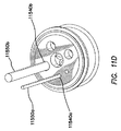
- FIG. 11D is a top perspective view of the gel cap illustrated in FIG. 11A with instruments inserted through two of the access ports.
- FIG. 11E is a bottom perspective view of the gel cap and instruments illustrated in FIG. 11D .
- FIG. 11F is a side view of the gel cap and instruments illustrated in FIG. 11D .
- FIG. 11G is a top perspective view of an embodiment of gel cap comprising a fixed camera or laparoscope port.
- FIG. 12 is a cutaway perspective view of an embodiment of an access device system comprising a gel cap that snap fits to a retractor.
- FIG. 13 is an exploded view of an embodiment of a trocar.
- FIGS. 14A and 14B are side views of an embodiment of a trocar comprising a fixation cannula in an insertion configuration and a fixation configuration, respectively.
- FIG. 15 is a side view of another embodiment of a trocar comprising a fixation cannula.
- FIG. 16A is a side view of another embodiment of a trocar comprising a fixation cannula.
- FIG. 16B is a perspective view of an embodiment of a bolster suitable for use with the trocar illustrated in FIG. 16A .
- FIG. 17A is a side view of another embodiment of a trocar comprising a fixation cannula.
- FIG. 17B is a perspective view of an embodiment of a bolster suitable for use with the trocar illustrated in FIG. 17A .
- Embodiments of a surgical instrument access device system are useful, for example, for single incision, single port, and/or limited port laparoscopic surgical procedures, for example, abdominal ( FIG. 1 ), transvaginal ( FIG. 2 ), transoral ( FIG. 3 ), and transanal ( FIG. 4 ) procedures.
- Various surgical instrument access devices are described in U.S. Patent Application Publication No. 2009/0187079, entitled “SURGICAL INSTRUMENT ACCESS DEVICE,” filed Jan. 22, 2009, and U.S. Pat. No. 7,727,146, entitled “WOUND REFRACTOR WITH GEL CAP,” both of which are incorporated by reference in their cntireties herein.
- FIG. 5 illustrates a perspective view of an embodiment of an access device system 5000 comprising a retractor 5100 and a cap 5500 , which is useful in single port and/or limited port procedures.
- the retractor or surgical wound retractor 5100 is placed and/or positioned into, across, and/or through a surgical incision and/or body orifice to enlarge, reshape, and/or isolate the incision or body orifice.
- the cap 5500 provides an artificial body wall through which instruments access the interior of a patient's body, for example, a body cavity.
- the components of the access device 5000 comprise any suitable biologically compatible materials.
- FIGS. 6-9 Two embodiments of natural orifice access ports or retractors 6100 , 7100 sharing certain similarities are illustrated in FIGS. 6-9 .
- One embodiment of retractor 6100 is illustrated in FIGS. 6A-6C, 7A, 8A-8C, and 9A .
- Another embodiment of retractor 7100 is illustrated in FIGS. 6D-6F, 7B, 8D, and 9B
- the embodiment of the natural orifice access port or retractor 6100 illustrated in a side view in FIG. 6A can be adapted for use in a transanal surgical procedure.
- the retractor 6100 comprises an inner or distal ring 6110 , an outer or proximal ring 6120 , a tubular body 6130 , and a funnel segment 6140 extending between and coupling the inner ring 6110 and the outer ring 6120 .
- the tubular body 6130 comprises a relatively flexible material such as a KRATON® material or a silicone rubber material, which is substantially cylindrical in the illustrated embodiment. In other embodiments, the tubular body 6130 has another shape, for example, an oval cross section.
- Some embodiments of the tubular body 6130 comprise one or more coatings that provide additional functionality, for example, an anti-microbial coating.
- Embodiments of the inner ring 6110 are sufficiently flexible and compliant to be compressed and/or deformed for insertion into a body orifice such as a patient's anus during a transanal surgical procedure. When subsequently released within an associated body cavity, the inner ring 6110 substantially returns to its original shape or footprint.
- the inner ring 6110 assumes a substantially circular shape in a relaxed state, for example, when released within a body cavity.
- the inner ring 6110 has another shape in the relaxed state, for example, an oval.
- the inner ring 6110 assumes a different shape when compressed for insertion through an incision or body orifice, for example, a substantially oval shape, a generally linear shape, a tear-drop shape, or another suitable shape.
- the inner ring 6110 in the relaxed state has a shape other than round, for example, oval, elliptical, or D-shaped.
- the inner ring 6110 is substantially rigid, that is, non-compliant under the ordinary conditions under which it is used.
- the inner ring extends outward from the surface of the tubular body, as shown, for example, in FIG. 6A , to thereby aid in retaining the retractor in the body cavity after it is deployed.
- Embodiments of the inner ring 6110 can comprise a generally circular cross section.
- the inner ring 6110 comprises another cross-sectional shape, for example, at least one of oval or elliptical, tear-drop shaped, and D-shaped.
- the inner ring 7110 can have a cross-sectional shape that is substantially flush with the tubular body 7130 of the retractor 7100 as further described herein.
- cross sections are used in other embodiments.
- some embodiments of the inner ring 6110 comprise at least one notch and/or weak spot, which facilitate folding or deforming the inner ring 6110 , thereby facilitating insertion and/or removal of the inner ring 6110 .
- the outer ring 6120 is proximal the funnel section 6140 .
- the outer ring 6120 has a substantially circular footprint.
- the outer ring 6120 can be sized and configured to sealingly couple to a cap or other access device thereon.
- one or more suture points 6160 can be disposed on the retractor 6110 adjacent the outer ring 6120 .
- outer ring 6120 has a generally circular profile. Additionally, in the illustrated embodiment, two suture points 6160 are generally diametrically opposed relative to the generally circular profile of the outer ring 6120 . In other embodiments, the retractor can include more or fewer than two suture points disposed of various locations relative to the outer ring 6120 .
- the tubular body 6130 has a generally circular profile defining a generally cylindrical passage 6150 .
- the generally cylindrical passage 6150 is desirably large enough to accommodate more than one laparoscopic instrument there through such that a single natural orifice access device can be used to provide access for multiple surgical instruments in a body cavity.
- generally cylindrical passage 6150 is desirably large enough such that multiple surgical instruments positioned there through can be translated or pivoted relative to one another, allowing a surgeon to manipulate the instruments as desired during a surgical procedure.
- the generally cylindrical passage extends between a proximal end 6152 of the retractor 6100 adjacent the outer ring 6120 to a distal end 6154 of the retractor 6100 adjacent the inner ring 6110 ( FIG. 6A ).
- the funnel segment 6140 provides a diametric reduction between the relatively large diameter of the outer ring 6120 , which is sized and configured to be removably coupled to an access device such as a cap, and the relatively smaller diameter of the passage 6150 , which is sized to fit within a natural orifice with minimal distention of the orifice.
- the funnel segment 6140 has an inner surface 6142 which can provide a bearing surface for an obturator used to advance to the retractor 6100 into a body cavity.
- the funnel segment 6140 can have a substantially linear taper between the relatively large diameter and the relatively smaller diameter such that the inner surface 6142 is a frusto-conical segment.
- the funnel segment 6140 can have a curved profile between the relatively large diameter and the relatively smaller diameter.
- a natural orifice access system can include a retractor 6100 and an optional obturator 6400 ( FIG. 6G-6H ).
- the obturator can have a proximal bearing surface 6410 sized and configured to bear against the inner surface 6142 of the funnel segment 6140 and a distal dilation surface 6420 sized and configured to expand a natural orifice for passage of the retractor 6100 .
- the dilation surface 6420 expands a pathway to a surgical site in a body cavity while the obturator bears on the inner surface 6142 of the funnel segment 6140 to advance the retractor 6100 into position in the surgical site.
- the obturator can have a handle 6430 at a proximal end thereof adapted to facilitate selective twisting or rotation of the obturator about a longitudinal axis thereof during insertion.
- the outer ring 6120 is relatively stiff compared with the relatively flexible tubular body 6130 of the retractor 6100 so that the outer ring 6120 can sealingly engage an access device such as a cap.
- FIG. 6C a perspective view of the retractor is illustrated with a partial cutaway of the outer ring 6120 .
- the outer ring 6120 includes an annular groove 6122 formed therein in which a reinforcing member 6124 is disposed.
- the reinforcing member 6124 can comprise a metallic member such as a wire formed into a ring shape.
- the reinforcing member 6124 can comprise a stainless steel ring positioned within the groove 6122 during manufacture of the retractor 6100 .
- the reinforcing number 6124 can comprise an injectable nonmetallic member.
- a glass filled polymer or polycarbonate material can be injected into the groove 6122 during manufacture of the retractor 6100 .
- retractor 6100 While the illustrated embodiments of retractor 6100 include a reinforcing member to enhance the rigidity of the outer ring 6120 , in other embodiments, the retractor 6100 can be formed in a multiple-shot molding process.
- an inner segment of the retractor defined by the tubular body 6130 and the inner ring 6110 is formed in one molding operation from a flexible material
- an outer segment of the retractor 6100 defined by the funnel segment 6140 and the outer ring 6120 is formed in another molding operation from a relatively rigid material such as a polycarbonate material or other suitable material.
- FIGS. 6D-F , 7 B, 8 D, and 9 B One embodiment of retractor 7100 formed in a multiple-shot molding process is illustrated in FIGS. 6D-F , 7 B, 8 D, and 9 B.
- the illustrated embodiment includes a continuous generally annular groove.
- a plurality of noncontiguous recesses can each receive one of a plurality of reinforcing members.
- the outer ring can include two or more concentric generally annular grooves, which each receive a corresponding reinforcing member.
- the tubular body 6130 is formed of a flexible material having a predetermined fixed length L, inner diameter D, and wall thickness T.
- the fixed length L, inner diameter D, and wall thickness T are selected to accommodate the anatomy of a natural orifice, such as the anal orifice of a majority of patients. It is contemplated that the retractor 6100 can be scaled to different sizes for patients of different ages.
- the retractor can include a telescopic tubular body such that the tubular body can be selectively positioned at a variety of lengths depending on patient anatomy and the location of the surgical site within the body cavity.
- the wall thickness T and material of the tubular body 6130 are selected such that the tubular body 6130 is resilient enough to maintain the passage 6150 there through when positioned in the natural orifice.
- the inner diameter, D is sufficiently large to accommodate multiple surgical instruments.
- the inner diameter D and thickness T can be sized such that an outer diameter of the retractor can be between approximately 30 mm and 70 mm, desirably between approximately 35 mm and 50 mm, and in one embodiment approximately 40 mm.
- the fixed length L is sufficiently long such that the inner ring 6110 can be positioned at a surgical site within a body cavity and the outer ring 6120 can be positioned outside the natural orifice.
- the fixed length L is of a length such that the device has an overall length between the proximal end 6152 and the distal end 6154 of between approximately 10 mm and approximately 100 mm, desirably between approximately 20 mm and 80 mm, more desirably between approximately 30 mm and 60 mm, and in one embodiment, approximately 40 mm.
- the annular groove 6122 can be open to an inner surface of the outer ring 6120 .
- the retractor 6100 can be formed of a flexible material in a single molding operation with the annular groove 6122 having an opening, and the reinforcing member 6124 can be subsequently inserted into the upper groove 6122 .
- the retractor 6100 can include a flexion region between the tubular body 6130 and the inner ring 6110 , such as an undercut 6170 .
- the flexion region can allow the inner ring 6110 to flex or rotate relative to the tubular body 6130 during insertion such that the inner ring 6110 presents a relatively small outer diameter in an insertion configuration and a relatively larger outer diameter in an undisturbed configuration.
- the inner ring 6110 can comprise an inflatable member such as an annular balloon coupled to a fluid source that can be selectively inflated and deflated between a deflated, relatively small diameter state for insertion and removal, and an inflated, relatively high diameter state for retention in a body cavity.
- an inflatable member such as an annular balloon coupled to a fluid source that can be selectively inflated and deflated between a deflated, relatively small diameter state for insertion and removal, and an inflated, relatively high diameter state for retention in a body cavity.
- the cap 6200 comprises a sealable access surface 6210 such as a gel pad surface as described in further detail herein.
- the cap 6200 can also comprise at least one gas or fluid port 6220 , 6230 .
- the cap 6200 comprises two gas or fluid ports 6220 , 6230 , such that one port can be used for gas insufflation and the other port can be used for ventilation for example when electrosurgery is performed through the access device.
- at least one of the gas or fluid ports 6220 , 6230 comprises a valve such as a stopcock valve to selectively control the flow of fluid there through.
- the sealable access surface 6210 can be encircled by and restrained by an annular frame 6240 such as a split ring having a clamp 6250 .
- the clamp 6250 can be movable between an open configuration in which the cap 6200 is selectively removable from the retractor 6100 and a clamped configuration in which the cap 6200 can be secured to the retractor 6100 .
- the annular frame 6240 can be positioned peripherally around the outer ring 6120 with the clamp 6250 in the open configuration and the clamp moved to the clamped configuration to sealingly fix the cap 6200 to the retractor 6100 . Accordingly, the cap 6200 can be easily removed during a surgical procedure to facilitate removal of excised tissue from a surgical site through the retractor 6100 .
- the clamp 6250 can have a distal flange 6252 positioned to interface with the outer ring 6120 of the retractor when the clamp is in the clamped configuration. As illustrated, the clamp 6250 engages a distal surface of the outer ring 6120 of the retractor 6100 .
- the annular frame 6240 can further comprise at least one distal flange sized and positioned to interface with a retractor.
- the annular frame 6240 comprises a distal flange 6260 positioned to engage a distal surface of the outer ring 6120 of the retractor.
- the flange 6260 is generally diametrically opposed to the distal flange of the clamp 6250 .
- the annular frame 6240 can include more than one distal flange positioned substantially equally spaced about the periphery of the annular frame 6240 or spaced irregularly about the periphery of the annular frame.
- FIG. 9A another embodiment of natural orifice access device is illustrated with a cap 6300 removably coupled to a retractor 6100 such as that described above with respect to FIGS. 6A-6C, 7A, 8A-8C, and 9A .
- the cap 6300 includes multiple trocar access devices 6310 positioned through an access surface 6320 thereof.
- the multiple trocar access devices 6310 allow for easy placement and manipulation of multiple laparoscopic instruments in a surgical site through a single natural orifice.
- the inner ring 6110 and the outer ring 6120 independently have different footprint shapes and/or footprint diameters.
- the inner ring 7110 can be substantially flush with the tubular body 7130 while the outer ring 7120 can be an annular member having a generally circular cross-section.
- An inner ring 6110 with a larger diameter permits a greater retraction force, but is more difficult to insert and remove from a body cavity.
- a natural orifice access port or retractor 7100 can be adapted for use in a transanal endoscopic microsurgery (TEMS) procedure.
- the retractor 7100 comprises an inner or distal ring 7110 , an outer or proximal ring 7120 , a tubular body 7130 , and a funnel segment 7140 extending between and coupling the inner ring 7110 and the outer ring 7120 .
- the tubular body 7130 comprises a relatively flexible material such as a KRATON® material or a silicone rubber material, which is substantially cylindrical in the illustrated embodiment. In other embodiments, the tubular body 7130 has another shape, for example, an oval cross section.
- Some embodiments of the tubular body 7130 comprise one or more coatings that provide additional functionality, for example, an anti-microbial coating.
- the inner ring 7110 is substantially flush with a distal end of the tubular body 7130 such that the retractor 7100 has a generally tubular configuration extending distally of the funnel segment 7140 to the distal end.
- Embodiments of the inner ring 7110 are sufficiently flexible and compliant to be compressed and/or deformed for insertion into a body orifice such as a patient's anus during a transanal surgical procedure. When subsequently released within an associated body cavity, the inner ring 7110 substantially returns to its original shape or footprint. In some embodiments, the inner ring 7110 assumes a substantially circular shape substantially flush with the generally cylindrical tubular body 7130 in a relaxed state, for example, when released within a body cavity.
- the inner ring 7110 has another shape in the relaxed state, for example, an oval.
- the inner ring 7110 assumes a different shape when compressed for insertion through an incision or body orifice, for example, a substantially oval shape, a generally linear shape, a tear-drop shape, or another suitable shape.
- the inner ring 7110 is substantially rigid, that is, non-compliant under the ordinary conditions under which it is used.
- the inner ring 7110 can be shaped and configured to facilitate insertion through a natural orifice.
- the inner ring 7110 can include a radiused edge to facilitate atraumatic entry through a natural orifice.
- the inner ring 7110 can include a beveled edge to facilitate entry through a natural orifice.
- the inner ring 7110 can be formed at an angle transverse to a longitudinal axis defined by the tubular body 7130 .
- such an angled inner ring 7110 can facilitate insertion of the retractor 7100 through a natural orifice.
- the inner ring 7110 can be substantially perpendicular to the longitudinal axis defined by the tubular body.
- the outer ring 7120 is proximal the funnel section 7140 .
- the outer ring 7120 has a substantially circular footprint.
- the outer ring 7120 can be sized and configured to sealingly couple to a cap or other access device thereon.
- one or more suture points can be disposed on the retractor 7100 adjacent the outer ring 7120 .
- the tubular body 7130 can have a generally circular profile defining a generally cylindrical passage 7150 .
- the generally cylindrical passage 7150 is desirably large enough to accommodate more than one laparoscopic instrument there through such that a single natural orifice access device can be used to provide access for multiple surgical instruments in a body cavity.
- generally cylindrical passage 7150 is desirably large enough such that multiple surgical instruments positioned there through can be translated or pivoted relative to one another, allowing a surgeon to manipulate the instruments as desired during a surgical procedure.
- the generally cylindrical passage extends between a proximal end 7152 of the retractor 7100 adjacent the outer ring 7120 to a distal end 7154 of the retractor 7100 adjacent the inner ring 7110 ( FIG. 6D ).
- the funnel segment 7140 provides a diametric reduction between the relatively large diameter of the outer ring 7120 , which is sized and configured to be removably coupled to an access device such as a cap, and the relatively smaller diameter of the passage 7150 , which is sized to fit within a natural orifice with minimal distention of the orifice.
- the funnel segment 7140 has an inner surface 7142 which can provide a bearing surface for an obturator used to advance to the retractor 7100 into a body cavity.
- the funnel segment 7140 can have a substantially linear taper between the relatively large diameter and the relatively smaller diameter such that the inner surface 7142 is a frusto-conical segment.
- the funnel segment 7140 can have a curved profile between the relatively large diameter and the relatively smaller diameter.
- a natural orifice access system can include a retractor 7100 and an optional obturator, such as described above with reference to FIG. 6G .
- the obturator can have a proximal bearing surface 6410 sized and configured to bear against the inner surface 7142 of the funnel segment 7140 and a distal dilation surface 6420 sized and configured to expand a natural orifice for passage of the retractor 7100 .
- the dilation surface expands a pathway to a surgical site in a body cavity while the obturator bears on the inner surface 7142 of the funnel segment 7140 to advance the retractor 7100 into position in the surgical site.
- the obturator can have a handle 6430 at a proximal end thereof adapted to facilitate selective twisting or rotation of the obturator about a longitudinal axis thereof during insertion.
- the outer ring 7120 is relatively stiff compared with the relatively flexible tubular body 7130 of the retractor 7100 so that the outer ring 7120 can sealingly engage an access device such as a cap.
- the retractor 7100 is formed in a multiple-shot molding process.
- an inner segment of the retractor 7100 defined by the tubular body 7130 and the inner ring 7110 is formed in one molding operation from a flexible material
- an outer segment of the retractor 7100 defined by the funnel segment 7140 and the outer ring 7120 is formed in another molding operation from a relatively rigid material such as a polycarbonate material or other suitable material.
- a multiple-shot molding process can be varied such that the resulting inner and outer segments are different from those of the illustrated embodiment.
- the inner segment can include the tubular body 7130 , the inner ring 7110 , and a portion of the funnel segment 7140
- the outer segment can include a portion of the funnel segment 7140 and the outer ring 7120 .
- the inner segment can include the inner ring 7110 and a portion of the tubular body 7130
- the outer segment can include a portion of the tubular body 7130 , the funnel segment 7140 , and the outer ring 7120 .
- a retractor 7100 formed in a multiple-shot molding process can include one or more retention members 7160 on the inner segment and the outer segment to maintain the position of the inner segment relative to the outer segment.
- a distal end of the outer segment can include one or more protrusions 7162 extending radially outwardly from the funnel segment 7140 and one or more recesses 7164 recessed radially inwardly from the funnel segment 7140 at an interface region of the inner segment and the outer segment of the retractor 7100 .
- the distal end of the outer segment includes a plurality of protrusions 7162 alternating with a plurality of recesses 7164 there between.
- the outer segment can include an annular groove 7170 formed in the funnel segment 7140 at an interface region of the inner segment and the outer segment of the retractor 7100 .
- the inner segment of the retractor 7100 can include an annular member 7166 disposed within and matingly engaging the groove 7170 to maintain the position of the inner segment relative to the outer segment.
- the tubular body 7130 is formed of a flexible material having a predetermined fixed length L 2 , inner diameter D 2 , and wall thickness T 2 .
- the fixed length L 2 , inner diameter D 2 , and wall thickness T 2 are selected to accommodate the anatomy of a natural orifice, such as the anal orifice of a majority of patients. It is contemplated that the retractor 7100 can be scaled to different sizes for patients of different ages.
- the retractor can include a telescopic tubular body such that the tubular body can be selectively positioned at a variety of lengths depending on patient anatomy and the location of the surgical site within the body cavity.
- the wall thickness T 2 and material of the tubular body 7130 are selected such that the tubular body 7130 is resilient enough to maintain the passage 7150 there through when positioned in the natural orifice.
- the inner diameter, D 2 is sufficiently large to accommodate multiple surgical instruments.
- the inner diameter D 2 and thickness T 2 can be sized such that an outer diameter of the retractor can be between approximately 30 mm and 70 mm, desirably between approximately 35 mm and 50 mm, and in one embodiment approximately 40 mm.
- the fixed length L 2 is sufficiently long such that the inner ring 7110 can be positioned at a surgical site within a body cavity and the outer ring 7120 can be positioned outside the natural orifice.
- the fixed length L 2 is of a length such that the device has an overall length between the proximal end 7152 and the distal end 7154 of between approximately 100 mm and approximately 200 mm, desirably between approximately 120 mm and 180 mm, more desirably between approximately 140 mm and 160 mm, and in one embodiment, approximately 150 mm.
- the cap 6200 comprises a sealable access surface 6210 such as a gel pad surface as described in further detail herein.
- the cap 6200 can also comprise at least one gas or fluid port 6220 , 6230 .
- the cap 6200 comprises two gas or fluid ports 6220 , 6230 , such that one port can be used for gas insufflation and the other port can be used for ventilation for example when electrosurgery is performed through the access device.
- at least one of the gas or fluid ports 6220 , 6230 comprises a valve such as a stopcock valve to selectively control the flow of fluid there through.
- the sealable access surface 6210 can be encircled by and restrained by an annular frame 6240 such as a split ring having a clamp 6250 .
- the clamp 6250 can be movable between an open configuration in which the cap 6200 is selectively removable from the retractor 7100 and a clamped configuration in which the cap 6200 can be secured to the retractor 7100 .
- the annular frame 6240 can be positioned peripherally around the outer ring 7120 with the clamp 6250 in the open configuration and the clamp moved to the clamped configuration to sealingly fix the cap 6200 to the retractor 7100 . Accordingly, the cap 6200 can be easily removed during a surgical procedure to facilitate removal of excised tissue from a surgical site through the retractor 7100 .
- FIG. 9B another embodiment of natural orifice access device is illustrated can include a cap 6300 substantially similar to that described above with reference to FIG. 9A removably coupled to a retractor 7100 such as that described above with respect to FIGS. 6D-F , 7 B, and 8 D.
- the cap 6300 can include multiple trocar access devices 6310 positioned through an access surface 6320 thereof.
- the multiple trocar access devices 6310 allow for easy placement and manipulation of multiple laparoscopic instruments in a surgical site through a single natural orifice.
- the retractors shown in FIGS. 7A and 7B can include a telescopic tubular body such that the tubular body can be selectively positioned at a variety of lengths depending on patient anatomy and the location of the surgical site within the body cavity.
- the tubular body may be formed in sections of varying length that slidingly engage and snap lock together to provide a variety of lengths, depending of the number and size of the sections selected and assembled.
- FIG. 7C a perspective view of a retractor 6500 is shown having three sections: an outer ring section 6510 , an inner ring section 6520 , and an intermediate section 6530 disposed between the other two sections.
- the three sections are held together by a snap lock mechanism 6540 .
- Each section terminates at the distal end with an annular groove 6550 that slidingly engages with the proximal end 6560 of the next section, best shown in the cross section view of FIG. 7D .
- the snap lock mechanism is shown in cross-section in FIG. 7E .
- the tubular body of the embodiment shown in FIG. 7C-E is preferably formed from a relatively stiff material, such as a polycarbonate.
- the tubular body of the retractor can include cut-out portions or windows 6570 , to provide access to regions of the anatomy that would otherwise be obscured by the tubular body while the retractor is in place.
- the retractor can be inserted into the body orifice or incision to provide retraction and to protect the lining of the body cavity, and then manipulated to align the window(s) to the sites of interest in the body cavity for access by surgical instruments.
- cut-out portions may be provided in retractors having tubular bodies of both rigid and flexible construction, as well as tubular bodies formed as a single piece or in sections.
- a flexible tubular body of a retractor may contain perforations.
- the tubular body can be cut or torn at the perforations to vary the length of the tubular body and/or to incorporate cut-out portions into the tubular body.
- the tubular body of such an embodiment is preferably formed from a relatively flexible material, such as KRATON® or PELLETHANE®.
- the trocar access devices 6310 have a relatively low profile, that is, protrude minimally above the access surface 6320 and/or below the distal surface of the cap 6300 . Accordingly, the trocar access devices 6310 are shorter than a length of a typical trocar and comprise a seal assembly positioned above the access surface 6320 and a cannula extending through the gel pad of the cap 6300 . The reduced length of the trocar access devices 6310 allows increased angular or pivotal motion for instruments extending there through, and also permits the use of curved and/or angled instruments.
- FIG. 9C is an exploded view of an embodiment of a trocar access device 6310 and optional obturator 6600 , which is a component of some embodiments of the access device system.
- the obturator 6600 comprises a pointed, puncture tip 6610 .
- the trocar access device 6310 comprises a proximal end, a distal end, and a longitudinal axis.
- the trocar access device 6310 comprises a cannula 6620 extending along the longitudinal axis.
- a trocar seal 6630 is disposed at the proximal end of the cannula 6620 , contained within a housing 6640 .
- a retainer 6650 is disposed at the distal end or tip of the cannula 6620 .
- the cannula 6620 comprises a tubular body dimensioned to accommodate an instrument or instruments received there through.
- the cannula 6620 is a substantially cylindrical tube, and extends through the cap 6300 in use.
- the cannula 6620 is comparatively short because the cannula need only traverse the cap 6300 ( FIG. 9A-B ), which has a known and consistent thickness, rather than a body wall. Accordingly, some embodiments of the cannula 6620 are not more than about 2-times longer, about 1.5-times longer, about 1.2-times longer, or about 1.1-times longer than the thickness of the gel pad.
- the cannula 6620 is less than about 20 mm, about 10 mm, or about 5 mm longer than the thickness of the gel pad. In some embodiments, the cannula 6620 is about as long as the gel pad is thick. In other embodiments, the cannula 6620 has a different length, for example, a length typical for a cannula used for traversing a body wall. Shorter length cannula permit increased angular degrees of freedom for instruments passing there through. Embodiments of shorter cannula also accommodate curved instruments.
- the cannula 6620 comprises any suitable biocompatible material. In some embodiments, the cannula 6620 comprises a flexible material.
- the illustrated trocar seal 6630 comprises an instrument or septum seal 6660 and a zero seal 6670 .
- a shield 6680 may be disposed within the instrument seal 6660 .
- the instrument seal 6660 seals instruments passing there through, thereby maintaining pressurization in a body cavity such as pneumoperitoneum or pneumorectum.
- the zero seal 6670 provides a seal when no instrument passes through the trocar seal 6630 .
- the instrument seal 6660 and zero seal 6670 are received in a housing 6640 disposed at the proximal end of the cannula 6620 and secured therein by a seal cover 6690 .
- the retainer 6650 is disposed at or near the distal end of the cannula 6620 .
- the retainer 6650 and cannula 6630 are integrated, while in other embodiments, the retainer 6650 and cannula 6630 are not integrated.
- the proximal end of the retainer 6650 comprises a flange 6655 that is generally flat and perpendicular to the longitudinal axis, while the distal end is tapered, narrowing toward the distal end of the cannula 6620 .
- the flange 6655 reduces the likelihood of accidental or inadvertent removal of the trocar access device 6310 from the cap.
- proximal face of the flange 6655 comprise additional anchoring features, for example, at least one of barbs, spikes, ridges, texturing, and the like, which are configured to penetrate or bite into a distal face of the cap 6300 .
- a diameter of the flange 6655 is from about 1.2 to about 2.5 times wider, or from about 1.5 to about 2.0 times wider than an outer diameter of the cannula 6630 .
- Some embodiments of the trocar access device 6310 are 5-mm trocars, in which the outer diameter of the cannula 6620 is from about 7 mm to about 8 mm.
- the tapered end of the retainer 6650 facilitates insertion of the trocar access device 6310 through the cap, either by itself, or when assembled with the obturator 6600 extending there through.
- the retainer 6650 is inserted through a performed opening in the cap 6300 .
- the retainer 6650 is secured to the cannula 6620 after the cannula 6620 is inserted through the cap.
- the cannula 6620 and retainer 6650 are secured mechanically, for example, using latches, screw threads, clips, lock rings, ratchets, and the like.
- the cannula 6620 and retainer 6650 are secured adhesively.
- the position of the retainer 6650 is adjustable, for example, to accommodate caps of different thicknesses.
- the cannula 6620 and/or retainer 6650 is secured to the cap, for example, adhesively.
- FIGS. 6A-6C, 7A, 8A-8C , and 9 A An embodiment of a procedure for retracting a body orifice is described with reference to the embodiments of the retractor 6100 illustrated in FIGS. 6A-6C, 7A, 8A-8C , and 9 A, and the embodiments of retractor 7100 illustrated in FIGS. 6D-6F, 7B, 8D, and 9B , although the procedure is applicable to all of the embodiments of the retractor disclosed herein.
- the surgical wound retractor 6100 , 7100 is inserted into a body orifice, such as the vagina ( FIG. 2 ), mouth ( FIG. 3 ) or anus ( FIG. 4 ).
- the inner ring 6110 , 7110 is folded or compressed into an oval or other suitable shape and urged through the incision or body orifice into an associated body cavity.
- the inner ring 6110 , 7110 is fully disposed within the associated body cavity, it is allowed to resume its original, relaxed shape, for example, substantially circular, oval, or other original shape.
- the inner ring 6110 is then pulled upward against the inner surface of the body cavity, for example, by pulling the outer ring 6120 upward.
- An outer surface of the tubular body 6130 , 7130 retracts the natural orifice.
- some embodiments of the access device 5000 comprise a cap, cover, or lid 5500 coupled to the outer ring of the retractor 5100 , which seals the retractor 5100 , for example, for maintaining pressurization within a body cavity such as pneumoperitoneum or pneumorectum.
- lid 5500 is removable, for example to provide access into the body cavity.
- Some embodiments of the lid 5500 comprise a transparent or translucent portion, thereby allowing a user to view into the body cavity without removing the lid 5500 .
- one embodiment of a lid 5500 is a gel cap.
- each of the inner ring 6110 , 7110 and outer ring 6120 , 7120 of the wound retractor includes independently variable design configurations.
- embodiments of the inner ring 6110 , 7110 and/or the outer ring 6120 , 7120 are rigid or flexible, and have footprints, cross-sectional shapes, and/or dimensions dependent on the intended use, for example, circular or oval footprints, diameters dependent on incision or orifice dimensions, or cross-sectional dimensions dependent on retraction force.
- the inner ring 6100 may extend radially out from the tubular body 6130 when deployed, stabilizing the retractor within the body orifice ( FIG. 7A ).
- the inner ring 7110 may be flush with the tubular body 7130 , as where, for example, the length L 2 of the tubular body is sufficient to stabilize the retractor within the body orifice ( FIG. 7B ).
- FIG. 10A illustrates in perspective an embodiment of a cap or cover 10500 , which is a surgical access device that seals the opening between the body cavity and the area outside the body cavity while providing access into the body cavity from outside the body cavity. More particularly, the illustrated cap 10500 releasably and sealingly couples to the outer ring 6120 ( FIG. 6A ), 7120 ( FIG. 6D ) of the wound retractor.
- the cap 10500 comprises a cap ring 10510 dimensioned and configured for coupling to the outer ring 6120 , 7120 of the wound retractor and a pad 10530 coupled to the cap ring 10510 .
- Embodiments of the cap 10500 provide an artificial body wall with consistent properties compared with a natural body wall, for example, thickness, compliance, rigidity, uniformity, and the like.
- the illustrated cap or cover 10500 is substantially circular.
- the gel cap 10500 has another shape or footprint, for example, oval, elliptical, parabolic, square, rectangular, or another suitable curved or polygonal shape.
- the outer ring 6120 , 7120 of the retractor and cap ring 10510 of the cap have the same general shape or footprint.
- the outer ring 6120 , 7120 of the retractor and cap ring 10501 of the cap have substantially different shapes, for example, a generally circular outer ring 6120 , 7120 and an oval cap ring 10510 .
- the outer ring 6120 , 7120 is distorted or reshaped for coupling to the cap ring 10510 , for example, by compressing opposed sides of the outer ring 6120 , 7120 .
- Non-circular shapes are useful, for example, for procedures in which space is limited. As discussed above, retracting a long, straight incision using an oval or elongated retractor requires less force than a similar procedure using a circular retractor.
- the pad 10530 comprises a gel.
- the pad 10530 is referred to as a “gel pad” and the cap 10500 is referred to as a “gel cap”.
- Descriptions of gel pads and gel caps generally apply to embodiments in which the pad 10530 does not comprise gel unless otherwise specified.
- the gel pad 10530 does not comprise any preformed access channels there through, for example, for instrument access. Instruments may be inserted directly through the gel pad 10530 , puncturing the gel pad 10530 , and thereby creating access channels or portions in the gel pad 10530 . Each access portion forms an instrument seal in the presence of an instrument inserted there through and a zero seal in the absence of an instrument inserted there through.
- the gel provides a gas tight seal around a variety of shapes and sizes of instruments inserted there through.
- Some embodiments of the gel pad 10530 also provide trocar access directly there through, which also provide instrument access into the body cavity.
- Embodiments of the gel pad 10530 have a working diameter of from about 40 mm to about 120 mm, which is the diameter of a portion of the gel pad 10530 through which instruments and/or trocars may be inserted.
- Embodiments of the gel cap 10500 are typically from about 10 mm to 50 mm wider than the working diameter.
- embodiments of the gel cap 10500 maintain pressurization within a body cavity such as pneumoperitoneum or pneumorectum during multiple instrument exchanges and substantially prevent unintentional loss of pressurization.
- Embodiments of the gel cap 10500 also provide substantially continuous access and visibility during surgery.
- Embodiments of the gel cap 10500 have a small profile for use in procedures with limited surgical space.
- the gel is an ultragel, which is characterized by an ultimate elongation greater than about 1000 percent and a durometer less than about 5 Shore A.
- Some embodiments of the ultragel comprising KRATON® and mineral oil exhibit an ultimate elongation exceeding about 1500 percent and improved sealing properties, for example, sealing with instruments of a wider size range than other seal materials.
- the seals comprising ultragels also form zero seals when the instrument is removed therefrom. Accordingly, in some embodiments of seals comprising ultragels, a single seal is acts as both the instrument seal as well as the zero seal.
- the cap ring 10510 comprise a substantially cylindrical ring comprising a proximal portion, a distal portion, and a longitudinal axis extending from the proximal portion to distal portions.
- the cap ring 10510 has another shape or footprint, for example, oval.
- FIG. 10B which is a bottom view of a cap ring 10510
- the proximal portion of the cap ring 10510 comprises a plurality of apertures 10512 distributed about the periphery thereof. The apertures 10512 extend through a wall 10514 at the proximal portion of the cap ring.
- the apertures 10512 are disposed in at least one member extending either longitudinally inward or longitudinally outward from the wall 10514 of the cap ring.
- the gel pad 10530 is disposed at the proximal portion of the cap ring 10510 in the illustrated embodiment, with portions of the gel pad 10530 extending through the apertures 10512 , thereby creating an interlocking structure between the cap ring 10510 and the gel pad 10530 , mechanically locking the cap ring 10510 and the gel pad 10530 together.
- the distal portion of the cap ring 10510 is substantially cylindrical in the illustrated embodiment, and is dimensioned and configured to receive the outer ring 6120 ( FIG. 6A ), 7120 ( FIG. 6D ) of the wound retractor.
- the cap ring 10510 comprises a latch mechanism 10516 that removably couples the cap ring 10510 to the outer ring 6120 , 7120 .
- latch mechanism 10516 that removably couples the cap ring 10510 to the outer ring 6120 , 7120 .
- other mechanisms are also useful for coupling the cap ring 10510 to the outer ring 6120 , 7120 of the wound retractor, for example, protruding lips, levers, clips, latches, tongues, grooves, screw threads, bayonet mounts, screws, friction fittings, compression fitting, snap caps, and the like.
- the outer ring 6120 , 7120 of the wound retractor when the outer ring 6120 , 7120 of the wound retractor is received in the distal portion of the cap ring 10510 , the outer ring 6120 , 7120 of the wound retractor contacts and embeds within a portion of the gel pad 10530 disposed at the distal portion of the cap ring 10510 , thereby displacing a portion of the gel, and forming a seal between the gel pad 10530 , and the outer ring 6120 , 7120 and tubular body 6130 , 7130 of the wound retractor.
- the distal portion of the gel pad 10530 is in juxtaposition with the incision or body orifice.
- the cap ring 10510 is permanently coupled or fixed to the outer ring 6120 , 7120 .
- the cap ring 10510 in some embodiments comprises a polymer.
- suitable polymers include, at least one of polyethylene (PE), low density polyethylene (LDPE), high density polyethylene (HDPE), ultra high molecular weight polyethylene (UHMWPE), polycarbonate, thermoplastic elastomers (DYNAFLEX®, GLS Corp.; KRATON®, Kraton Polymers), polyphenylene oxide (PPO), polystyrene, and the like.
- the polymer component of the cap ring is fabricated by any suitable method, including injection molding, melt casting, blow molding, and the like.
- Some embodiments of a process in which the gel pad 10530 is cast in the cap ring 10510 are include steps performed at temperatures above about 130° C. over several hours, for example, from about three (3) to about four (4) hours. Accordingly, in some of these embodiments, the cap ring 10510 does not deform under these conditions.
- Some embodiments of the gel pad 10530 comprise an elastomeric gel. Examples of such gels are described in U.S. patent application Ser. No. 10/381,220, filed Mar. 20, 2003, the disclosure of which is hereby incorporated by reference as if set forth in full herein.
- Embodiments of the gel are prepared by mixing at least one triblock copolymer with a solvent that dissolves the midblocks of the triblock copolymer. The mixture is typically a slurry.
- the endblocks typically comprise a thermoplastic material, such as styrene, while the midblocks typically comprise a thermoset elastomer such as, ethylene/butylene, isoprene, or butadiene.
- the triblock copolymer examples include styrene-ethylene/butylene-styrene (SEBS), styrene-isoprene-styrene (SIS), and styrene-butadiene-styrene (SBS).
- SEBS styrene-ethylene/butylene-styrene
- SIS styrene-isoprene-styrene
- SBS styrene-butadiene-styrene
- the solvent is an oil, for example, mineral oil.
- the triblock copolymer used is KRATON® G1651, which has a styrene to rubber ratio of 33/67.
- the gel is substantially permanent and, by the nature of the endblocks, processable as a thermoplastic elastomer henceforward.
- the mixture or slurry has a minimum temperature at which it becomes a gel, which is referred to as the minimum gelling temperature (MGT).
- MGT minimum gelling temperature
- This temperature typically corresponds to the glass transition temperature of the thermoplastic endblock plus a few degrees.
- the MGT for a mixture of KRATON® G1651 and mineral oil is about 120° C.
- Some embodiments of the gel comprise a diblock copolymer, either instead of or in addition to the triblock copolymer.
- Embodiments of the diblock copolymer comprise a thermoplastic first endblock, for example, styrene, and a thermoset elastomeric second endblock, for example, ethylene/butylene, isoprene, or butadiene.
- An example of a suitable diblock copolymer is styrene-ethylene/butylene (SEB).
- the entire mass of the slurry is heated to or above the MGT and held at or above the MGT for a sufficient time for the end blocks to form a network or matrix of interconnections.
- the slurry will continue to form a gel at temperatures between the MGT and temperatures at which the components of the slurry/gel begin to decompose and/or oxidize.
- the mineral oil in the slurry/gel will begin to be volatile and oxidize. Oxidizing may cause the gel to turn brown and become oily.
- the speed at which a given volume of slurry forms a gel depends on the speed with which the entire mass of slurry reaches the MGT. Also, at temperatures higher than the MGT, the end block networks distribute and form more rapidly, thereby speeding the gel formation.
- KRATON® G1701X is a mixture of seventy percent (70%) SEB and thirty percent (30%) SEBS, with an overall styrene to rubber ratio of 28/72.
- Those skilled in the art will appreciate that an almost unlimited number of combinations, alloys, and styrene to rubber ratios can be formulated, each providing and embodiment exhibiting one or more advantages, for example, low durometer, high elongation, and good tear strength.
- the gel material further comprise a polymer that, with a foaming agent, improves the sealing properties of the gel, for example, silicone, soft urethanes, and even harder plastics.
- a polymer that, with a foaming agent improves the sealing properties of the gel
- silicones include those used for electronic encapsulation.
- suitable harder plastics include polyvinylchloride (PVC), isoprene, KRATON® neat, and other KRATON®/oil mixtures.
- suitable oils include vegetable oils, petroleum oils, and silicone oils, as well as mineral oil.
- Some embodiments of the gel comprise one or more additives that provide one or more desirable properties, for example, at least one of enhanced lubricity, improved appearance, and wound protection.
- Additives are incorporated directly into the gel and/or applied as a surface treatment.
- other compounds are added to the gel to modify its physical properties and/or to assist in subsequent modification of the surface by providing bonding sites and/or surface charges.
- oil-based colorants are added to the slurry to create gels of different colors in some embodiments.
- Some embodiments of the gel pad 10530 comprise a layer of polyethylene on at least one surface.
- Polyethylene is dissolved in mineral oil and the solution applied to one or more surfaces of the gel pad 10530 .
- the mineral oil does not evaporate, but instead, absorbs into the gel pad over time, leaving behind the polyethylene as a layer on the surface of the gel pad.
- the triblock copolymer/solvent mixture/slurry used to manufacture the gel pad 10530 comprises about ninety percent (90%) by weight of mineral oil and about ten percent (10%) by weight of KRATON® G1651. From a thermodynamic standpoint, this mixture behaves similarly to mineral oil. Because mineral oil has a relatively high heat capacity, transforming 0.45 kg (1 pound) of the slurry into a homogenous gel at about 130° C. may take from bout three (3) to about four (4) hours. Once formed, the gel can be cooled as quickly as practicable with no apparent deleterious effects on the gel. In some embodiments, the gel is cooled by cold-water immersion. In other embodiments, the gel is air-cooled. Those skilled in the art will recognize that other cooling techniques are used in other embodiments.
- KRATON®/oil gel Certain properties of the KRATON®/oil gel will vary with the weight ratio of the components. In general, a higher proportion of mineral oil results in a softer gel, while a higher proportion of KRATON® results in a firmer gel.
- a too-soft gel exhibits excessive tenting or doming of the gel cap 10500 during surgery when a patient's body cavity is insufflated. Some embodiments of gels that are too soft also do provide an adequate instrument seal and/or zero seal. The gel should be sufficiently soft to provide an adequate seal both in the presence of an instrument and in the absence of an instrument, however.
- the copolymer, such as KRATON®, and the solvent, such as mineral oil, in the slurry may separate.
- the slurry may be mixed to greater homogeneity, for example, with a high shear mixer. Mixing the slurry may introduce or add air to the slurry, however.
- the slurry may be degassed.
- the slurry is degassed under a vacuum, for example, within a vacuum chamber.
- the applied vacuum is about 0.79 meters (about 29.9 inches) of mercury, or about one (1) atmosphere.
- stirring or mixing the slurry under vacuum facilitates removal of the air.
- the slurry typically expands, then bubbles, and then reduces in volume.
- the vacuum is typically discontinued when the bubbling substantially ceases.
- Degassing the slurry in a vacuum chamber reduces the volume of the slurry by about ten percent (10%). Degassing the slurry also reduces oxidation of the finished gel in some embodiments.
- a gel made from a degassed slurry comprising about 91.6% by weight of mineral oil and about 8.4% by weight of KRATON® G1651, an eleven-to-one ratio, has about the same firmness as a gel made from a slurry that is not degassed and that comprises about ninety percent (90%) by weight of mineral oil and about ten percent (10%) by weight of KRATON® G1651, a nine-to-one ratio.
- the two components will separate after mixing, with the less dense mineral oil rising to the top of the container. This phase separation typically occurs when transforming a static slurry into a gel over several hours. Consequently, the resulting gel is non-homogeneous, with a higher concentration of mineral oil at the top and a lower concentration at the bottom.
- the speed of separation is a function of the depth or head height of the slurry being heated. Factors relevant to the relative homogeneity of the gel include the mass of slurry, the head height, the temperature at which the gel sets, and the speed at which the energy is transferred to the gel.
- the gel pad 10530 or gel cap 10500 are gamma sterilized in some embodiments, which is relatively and/or comparatively simpler to qualify compared with other sterilization process, for example, versus ethylene oxide.
- Gamma sterilization can cause large bubbles to form in the gel pad, however, which are cosmetic and/or aesthetic issues in the sterilized devices.
- bubbles typically comprise greater than ninety-nine percent (99%) room air, the dissolved air is advantageously removed from the slurry prior to transforming the slurry into a gel.
- the slurry may be degassed under vacuum, as described above, then gelled by heating.
- Some bubbles may still form in the gel during gamma sterilization, but typically disappear over a period of from about twenty-four (24) hours to about seventy-two (72) hours.
- mineral oil at room temperature has about ten percent (10%) dissolved gas.
- removing air from the gel makes the gel firmer. This effect is counterbalanced by a softening of the gel by the gamma radiation during gamma sterilization, however.
- the gel pad 10530 is gamma sterilized
- the gel comprises about ninety percent (90%) mineral oil by weight and about ten percent (10%) KRATON® by weight.
- degassing the slurry makes the gel firmer.
- the counteracting softening by the gamma radiation results in a gel with substantially the same firmness as a gel comprising about ninety percent (90%) mineral oil by weight and about ten percent (10%) KRATON® by weight that is not degassed and gamma sterilized.
- the gel pad 10530 is coupled to, attached to, formed with, or integrated with the cap ring 10510 to provide a gas-tight seal between the cap ring 10510 and the tubular body 6130 ( FIG. 6A ), 7130 ( FIG. 6D ).
- the gel pad 10530 covers and seals the entire opening in the cap ring 10510 , as well as covering substantially the entire wound or orifice opening. As stated above, the gel pad 10530 provides a gas tight seal around a variety of shapes and sizes of instruments inserted there through.
- the polystyrene component of KRATON® in the gel pad 10530 improves adhesion with polyphenylene oxide (PPO), polystyrene, and other similar polymers.
- the polycarbonate component of the cap ring 10510 does not bond with the gel pad 10530 at 130° C., which is a typical manufacturing temperature for a gel pad 10530 comprising KRATON®. Raising the temperature to about 150° C. for a few minutes during casting, however, bonds the gel pad 10530 to the cap ring 10510 . It is believed that heating the gel pad 10530 and cap ring 10510 to a temperature at which both the polystyrene component of the gel and the polycarbonate are simultaneously above their melt points allows bonds to form there between. In other embodiments, the uncured gel and the cap ring 10510 are heated to near or at the glass transition temperature of the polycarbonate in the cap ring 10510 , thereby bonding the gel pad 10530 to the cap ring 10510 .
- the gel comprises mineral oil and the cap ring 10510 comprises a polymer that dissolves in mineral oil under the manufacturing conditions, for example, polyethylene (PE), low density polyethylene (LDPE), high density polyethylene (HDPE), and ultra high molecular weight polyethylene (UHMWPE).
- PE polyethylene
- LDPE low density polyethylene
- HDPE high density polyethylene
- UHMWPE ultra high molecular weight polyethylene
- PE polyethylene
- PE has a higher molecular weight than mineral oil and dissolves in mineral oil at the temperatures used to cast the gel pad 10530 .
- a portion of the PE in the cap ring 10510 dissolves in the mineral oil in the gel pad 10530 at the processing temperatures, for example, above about 130° C., a bond between the PE in the cap ring 10510 and gel pad 10530 is formed.
- the cap ring 10510 is placed into a mold that together with the cap ring 10510 includes a negative space in the desired shape of the gel pad and uncured gel is added to the mold. Sufficient uncured gel is then added to the mold to cover and fill the apertures 10512 . The uncured gel flows through, fills, and remains within the apertures. Also, in some embodiments, the mold is filled with sufficient uncured gel to extend into the distal portion of the cap ring 10510 . After the gel cures, the gel in the apertures connects and couples the gel on a first side of each aperture 10512 to the gel on a second side of the aperture, thereby mechanically locking the gel pad 10530 to the cap ring 10510 .
- Some embodiments include another method for coupling the gel pad 10530 to the cap ring 10510 , either in addition to or instead of the mechanical interlocking discussed above. Such methods are useful, for example, for coupling separately formed gel pads or gel slugs 10530 and cap rings 10510 .
- Some embodiments use a glue or adhesive to couple the gel pad 10530 to the cap ring 10510 , for example, cyanoacrylate (SUPERGLUE® or KRAZY GLUE®). The glue is believed to bond to either the rubber or the styrene component of the triblock copolymer with a bond is frequently stronger than the gel material itself.
- Some embodiments use solvent welding in which a solvent dissolves a plastic in the cap ring 10510 and the polystyrene in the gel pad 10530 .
- the solvent is applied to the gel pad 10530 and cap ring 10510 by any suitable method, for example, by spraying and/or by dipping. In effect, the solvent melts both the plastic of the cap ring 10510 as well as the polystyrene in the gel pad 10530 , thereby forming a bond between the two, which remains after the solvent evaporates.
- the gel pad 10530 is cast into the cap ring 10510 to form the gel cap 10500 .
- the cap ring 10510 is positioned in or placed into a mold cavity of a casting mold.
- Embodiments of the mold cavity include support for the annular walls of the cap ring 10510 .
- Embodiments of the mold comprise a material with sufficient heat dissipation properties, for example, at least one of aluminum, copper, and brass. Those skilled in the art will recognize that other mold materials with lower heat dissipation properties will produce acceptable parts in some embodiments.
- some embodiments of the mold comprise active cooling elements, for examples, channels through which coolants are pumped.
- the mold cavity and cap ring 10510 assembly is then filled with a desired amount of the triblock copolymer/mineral oil slurry such that the slurry contacts the cap ring 10510 .
- the slurry is preheated, for example, to about 52° C. (125° F.), which facilitates a complete filling of the mold cavity by the slurry, thereby reducing the probability of voids in the gel.
- Preheating the slurry to a temperature below the MGT reduces the viscosity of the slurry and allows the slurry to flow more easily.
- some embodiments of the slurry are degassed in a vacuum before casting.
- the slurry is also degassed after it is filled in the mold cavity to remove any air that may have been introduced during the filling of the mold cavity, as well as to facilitate flow of the slurry into voids in the mold.
- the mold, cap ring, and slurry are heated, for example, in an oven, until the slurry reaches a temperature of about 150° C.
- the slurry turns into gel at about 120° C.; however, at about 150° C., the gel bonds to a polycarbonate cap ring 10510 .
- bonding may take place at a temperature other than about 150° C.
- the gel pad 10530 is molded separately as a gel slug, which is then bonded to the cap ring 10510 as discussed above.
- the gel cap 10500 When the transformation of the slurry into a gel is complete, for example, when the temperature of the gel pad reaches about 150° C., the gel cap 10500 is cooled, for example, by air-cooling, cold-water immersion, or another suitable method. At 150° C. the gel pad 10530 is soft and easily distorted. Distortions in the gel pad 10530 present during cooling would be set after cooling. Accordingly, in some embodiments, the gel cap 10500 is cooled within the mold, thereby reducing the likelihood of distorting the gel pad 10530 . Factors affecting the cooling time include the size and configuration of the mold, the quantity of gel, temperature and quantity of cooling medium, the properties of the cooling medium, and the mold material.
- the cooling time for a particular gel cap 10500 may be about two (2) hours for air cooling and about fifteen (15) minutes for water cooling. Whether cooling with air or water, the final properties of the gel are substantially the same.
- the gel cap 10500 is typically cooled to about ambient room temperature, but may be cooled to a lower temperature if desired. At about 0° C., the gel hardens, which is useful, for example, in secondary operations such as when coupling separately manufactured gel pads 10530 and cap rings 10510 .
- the gel cap 10500 may be removed from the mold at any time after the gel has set.
- the gel pad 10530 When removed from the mold, the gel pad 10530 typically has a tacky surface. Coating the gel pad 10530 with a powder, such as cornstarch, substantially reduces or eliminates the tackiness of the cured gel pad 10530 .
- the gel pad 10530 is molded separately from the cap ring 10510 , and coupled to the cap ring 10510 in a secondary operation, for example, bonding.
- the gel pad 10530 is molded as a gel slug with an outer perimeter smaller than the perimeter of the inner cylindrical wall of the cap ring 10510 and a height greater than the height of the cap ring 10510 . Because the gel pad 10530 is molded separate from the cap ring 10510 , the slurry need only be heated to the MGT, for example, about 120° C., to complete the transformation of the slurry into a gel, whereupon the gel becomes substantially transparent. As discussed above, the gel slug may be cooled, for example, to about 0° C., then placed within the inner cylindrical wall of the cap ring 10510 .
- the gel slug is coupled to the cap ring 10510 through compression molding, in which the gel slug is compressed longitudinally, thereby expanding the outer perimeter of the gel slug and compressing the gel slug against the inner cylindrical wall of the cap ring 10510 .
- the compressed gel slug and cap ring 10510 are then heated to a sufficient temperature for the polystyrene in the gel and the polymer of the cap ring 10510 to form bonds there between. Molding the gel slug separately from the cap ring 10510 followed by heat bonding the gel slug to the cap ring is especially useful in embodiments in which the cap ring 10510 comprises a material with a melting temperature lower than the MGT of the gel. In such situations, the gel slug can be molded separately and heat bonded to the cap ring 10510 without melting the cap ring 10510 .
- An embodiment of a method for retracting an incision or body orifice using the retractor 6100 , 7100 is discussed in detail above.
- the method results in the outer ring 6120 , 7120 of the retractor substantially in contact with the exterior surface of the body wall.
- the gel cap 10510 is then coupled to the outer ring 6120 , 7120 of the retractor, thereby sealing the opening between the body cavity and the area outside the body cavity and allowing the surgeon to insufflate the body cavity.
- embodiments of the gel cap 10500 comprise no preformed access channels in the gel pad 10530 .
- instruments may be inserted directly through the gel pad 10530 , thereby creating access channels through the gel pad 10530 .
- Each access channel created in the gel cap forms an instrument seal in the presence of an instrument passing there through because the gel provides a gas tight seal around a variety of shapes and sizes of instruments.
- the channel created in the gel pad by the instrument closes to form a zero seal.
- Some embodiments of the cap use access devices such as trocars inserted through the gel pad 10530 for instrument access, in particular, where an access channel experiences repeated instrument manipulation, for example, insertion, removal, advancement, retraction, rotation and/or other manipulation.
- access devices such as trocars inserted through the gel pad 10530 for instrument access, in particular, where an access channel experiences repeated instrument manipulation, for example, insertion, removal, advancement, retraction, rotation and/or other manipulation.
- Each trocar inserted through the gel pad 10530 permits repeated introduction, removal, and/or manipulation of instruments there through.
- the gel cap 10500 initially comprises no access channels, and the surgeon is at liberty to determine the placement of instruments there through. Moreover, the surgeon has unlimited flexibility in the placement and repositioning of ports within the area of the gel cap 10500 , as well as the option of selecting different trocar sizes for different clinical procedures. Being detachable, the gel cap 10500 allows for the removal of large specimens. Once removed, the gel cap 10500 can be re-coupled to the outer ring 6120 , 7120 of the retractor, thereby restoring the seal and allow the surgeon to re-insufflate the body cavity.
- embodiments of the gel are deformable without losing physical integrity, and while maintaining substantially gas tight instrument seals with any instruments extending there through, as well as gas tight zero seals for any access channels without any instruments extending there through.
- embodiments of the gel cap 10500 permit both translational or positional, and angular or pivotal “float” or degrees of freedom for the instruments passing through the gel pad 10530 . This float permits instrument motion both relative to the cap ring 10510 as well as relative to other instruments. In contrast, other single or limited port systems do not exhibit one or both translational or angular float for instruments.
- FIG. 11A is a top view of an embodiment of a gel cap 11500 comprising a plurality of access ports, seals, or sealing valves disposed in the gel pad.
- FIG. 11B is a perspective top view of the gel cap 11500 mounted on a retractor.
- FIG. 11C is a perspective bottom view of the gel cap 11500 mounted on a retractor.
- the gel cap 11500 comprises a cap ring 11510 and a gel pad 11530 , which are generally similar to the cap ring and gel pad of the embodiment described above.
- the gel cap 11500 further comprises a plurality of access ports 11540 , at least a portion of which is disposed within or embedded within the gel pad 11530 .
- the access ports 11540 have a low profile, that is, do not protrude or protrude minimally above the proximal surface of the gel pad 11530 and/or below the distal surface of the gel pad 11530 .
- the lengths of the access ports 11540 are similar to the thickness of the gel pad 11530 , which is shorter than a length of a typical trocar inserted in the gel pad 11530 , which comprises a seal assembly positioned above the gel pad 10530 , and a cannula extending through the gel pad 11530 .
- the reduced length of the access port 11540 allows increased angular or pivotal motion for instruments extending there through, and also permits the use of curved and/or angled instruments.
- the access ports 11540 are substantially permanent or non-removable under the conditions under which the gel cap 11500 is used. Trocars can also be inserted through the gel pad 11530 if additional ports are desired.
- Each port 11540 comprises longitudinal axis extending from a proximal side to a distal side of the gel pad 11530 , a first seal 11542 disposed at the proximal side of the gel pad 11530 , and a second seal 11544 disposed distal to the first seal 11542 .
- a sight of each of the ports or seals 11540 has an aperture through the gel pad 11530 and coincides with the longitudinal axis.
- the first seal 11542 forms an instrument seal with an instrument extending there through and the second seal 11544 forms a zero seal in the absence of an instrument extending there through.
- the first seal 11542 comprises a septum seal.
- Each septum seal comprises an aperture 11546 there through that is slightly smaller than a cross-section of the smallest instrument to be inserted there through.
- the aperture 11546 of the septum seal is substantially aligned with the aperture through the gel pad and the longitudinal axis of the port 11540 .
- the aperture 11546 expands and engages the outer surface of the instrument, thereby forming a seal therewith.
- the septum seal comprises an elastomeric material that biases the aperture against an instrument is inserted there through.
- the second seal 11544 comprises a double-duckbill valve, which functions as a zero-closure seal that provides a zero seal in the absence of an instrument inserted there through.
- the second seal comprises another type of seal, for example, a duckbill valve, a flap valve, and the like.
- the double-duckbill valve comprises as elastomeric material.
- each of the first seal 11542 and the second seal 11544 independently comprise an elastomeric material, for example, at least one of rubber, synthetic rubber, silicone, ethylene propylene diene monomer (EPDM), ethylene-propylene copolymer (EP rubber), polyisoprene, polybutadiene, polyurethane, styrene-butadiene, ethylene vinyl acetate (EVA), polychloroprene (NEOPRENE®), perfluorelastomer (KALREZ®), and the like
- the septum seal provides an instrument seal in the presence of an instrument inserted there through
- the duckbill valve provides a zero seal in the absence of an instrument inserted there through.
- the illustrated embodiment comprises ports or seals 11540 in the gel pad of different sizes. Each size of port 11540 sealing accommodates a different range of instrument sizes inserted there through.
- the size of a port is typically given as the diameter of the largest instrument that the port will accommodate, for example, 5 mm, 11 mm, or 12 mm FIGS.
- 11D, 11E, and 11F are a perspective top view, a perspective bottom view, and a side view of a thinner instrument 11550 a and a thicker instrument 11550 b inserted through a smaller port 11540 a and a larger port 11540 b , respectively, of the embodiment of the gel cap 11500 illustrated in FIGS. 11A-11C .
- FIG. 11G is a top perspective view of an embodiment of a gel cap 11500 further comprising a fixed port position, for example, for a camera or a laparoscope.
- the fixed port 11560 comprises a lock mechanism 11562 that maintaining the position of a camera or laparoscope inserted there through.
- one of the ports 11540 further comprises a stopcock and/or gas fitting used as a gas inlet and/or outlet port for insufflating, depressurizing, and/or venting the body cavity of gas.
- a gas inlet/outlet port is disposed on the cap ring 11510 .
- FIG. 12 is a cutaway perspective view of an embodiment of an access device system 12000 comprising retractor 12100 and a cap or cover 12500 , which are similar to embodiments of retractors and gel caps described above.
- the retractor 12100 comprises an inner ring 12110 , an outer ring 12120 , and a sleeve 12130 extending between the inner ring 12110 and the outer ring 12120 .
- the cap 12500 is a gel cap comprising a proximal side, a distal side, a cap ring 12510 , and a gel pad 12530 .
- the cap ring 12510 comprises a tubular ring dimensioned to receive the outer ring 12120 of the retractor therewithin.
- the distal side of the cap ring 12510 comprises an annular slot 12520 , which is sufficiently radially deformable for the outer ring 12120 to reversibly pass there through. Accordingly, the illustrated embodiment of the cap ring 12510 secures the cap 12500 to the outer ring 12120 with a snap or friction fit.
- FIG. 13 is an exploded view of an embodiment of a trocar 13800 and optional obturator 13900 , which is a component of some embodiments of the access device system.
- the obturator 13900 comprises a pointed, puncture tip 13910 .
- potential damage to underlying tissue by contact with the tip 13910 is reduced because the gel pad 10530 serves as an artificial body wall that is spaced from the underlying tissue as discussed above.
- the obturator tip 13910 has another shape, for example, blunt and/or bladeless, which, for example, reduces the likelihood of damage to other components of the access system, for example, a retraction sheath of a retractor.
- the trocar 13800 comprises a proximal end, a distal end, and a longitudinal axis.
- the trocar 13800 comprises a cannula 13810 extending along the longitudinal axis.
- a trocar seal 13820 is disposed at the proximal end of the cannula 13810 .
- a retainer 13830 is disposed at the distal end or tip of the cannula 13810 .
- the distal end or tip of the cannula 13810 is not angled.
- Other embodiments comprise an angled distal end or tip of the cannula 13810 .
- the illustrated embodiment of the trocar 13800 does not comprise an insufflation gas inlet.
- the trocar 13800 is typically used in procedures in which a body cavity is not insufflated, or in which insufflation is provided through another device.
- Other embodiments of trocars are disclosed in U.S. patent application Ser. No. 11/677,994, filed Feb. 22, 2007, the disclosure of which is incorporated by reference.
- the cannula 13810 comprises an elongate, tubular cannula body 13812 dimensioned to accommodate an instrument or instruments received there through.
- the cannula body 13812 is a substantially cylindrical tube, and extends through the gel pad 10530 in use.
- the cannula body 13812 extends from the proximal end of the cannula 13810 to which the trocar seal 13820 is coupled, and which has a larger outer diameter than the cannula body 13812 .
- the cannula 13810 is comparatively short because the cannula body 13812 need only traverse the gel pad 10530 ( FIG. 10A ), which has a known and consistent thickness, rather than a body wall. Accordingly, some embodiments of the cannula body 13812 are not more than about 2-times longer, about 1.5-times longer, about 1.2-times longer, or about 1.1-times longer than the thickness of the gel pad. In some embodiments, the cannula body 13812 is less than about 20 mm, about 10 mm, or about 5 mm longer than the thickness of the gel pad. In some embodiments, the cannula body 13812 is about as long as the gel pad is thick.
- the cannula body 13812 has a different length, for example, a length typical for a cannula used for traversing a body wall. Shorter length cannula bodies permit increased angular degrees of freedom for instruments passing there through. Embodiments of shorter cannula bodies also accommodate curved instruments.
- the cannula 13810 comprises any suitable biocompatible material. In some embodiments, the cannula 13810 comprises a flexible material.
- the illustrated trocar seal 13820 comprises an instrument or septum seal 13822 and a zero seal 13824 .
- the instrument seal 13822 seals instruments passing there through, thereby maintaining pressurization in a body cavity such as pneumoperitoneum or pneumorectum.
- the zero seal 13824 provides a seal when no instrument passes through the trocar seal 13820 .
- the instrument seal 13822 and zero seal 13824 are received in a housing 13826 disposed at the proximal end of the cannula 13810 and secured therein by a seal cover 13828 .
- the retainer 13830 is disposed at or near the distal end of the cannula 13810 .
- the distal end of the cannula 13810 is generally perpendicular to the longitudinal axis thereof, or not angled.
- Other embodiments comprise an angled distal end or tip.
- the retainer 13830 and cannula 13810 are integrated, while in other embodiments, the retainer 13830 and cannula 13810 are not integrated.
- the proximal end of the retainer 13830 comprises a flange 13832 that is generally flat and perpendicular to the longitudinal axis, while the distal end is tapered, narrowing toward the distal end of the cannula 13810 .
- the flange 13832 reduces the likelihood of accidental or inadvertent removal of the trocar 13800 from the gel pad.
- Some embodiments of the proximal face of the flange 13832 comprise additional anchoring features, for example, at least one of barbs, spikes, ridges, texturing, and the like, which are configured to penetrate or bite into a distal face of the gel pad 10530 .
- a diameter of the flange 13832 is from about 1.5 to about 2.5 times wider, or from about 2 to about 2.2 times wider than an outer diameter of the cannula body 13812 .
- Some embodiments of the trocar 13800 are 5-mm trocars, in which the outer diameter of the cannula body 13812 is from about 7 mm to about 8 mm.
- the tapered end of the retainer 13830 facilitates insertion of the trocar 13800 through the gel pad, either by itself, or when assembled with the obturator 13900 extending there through.
- the retainer 13830 is inserted through a preformed opening in the gel pad 10530 . Because embodiments of the gel material of the gel pad 10530 have high elongation values, as discussed above, the retainer 13830 is insertable through a relatively small opening in the gel pad 10530 , yet resists inadvertent removal, as discussed above.
- the retainer 13830 is secured to the cannula 13810 after the cannula 13810 is inserted through the gel pad.
- the cannula 13810 and retainer 13830 are secured mechanically, for example, using latches, screw threads, clips, lock rings, ratchets, and the like.
- the cannula 13810 and retainer 13830 are secured adhesively.
- the position of the retainer 13830 is adjustable, for example, to accommodate gel pads of different thicknesses.
- the cannula 13810 and/or retainer 13830 is secured to the gel pad, for example, adhesively.
- FIG. 14A is a side view of another embodiment of a trocar 14800 that is suitable as a component of a single-port surgical access system described above, for example, comprising a gel pad 10530 and retractor.
- Some embodiments of the access system comprise a plurality of trocars 14800 .
- the trocar 14800 is generally similar to the trocar 13800 described above, and comprises a cannula 14810 , a trocar seal assembly 14820 , and a retainer 14830 , which are generally similar to the corresponding features described above.
- the illustrated embodiment of the trocar 14800 further comprises a bolster 14840 and a locking component 14850 .
- the illustrated embodiment of the cannula 14810 is also referred to as a “fixation cannula” as will become apparent from the discussion below.
- the bolster 14840 comprises a torus or doughnut.
- a cannula body 14812 extends through an opening in the bolster 14840 .
- a diameter of the opening of the bolster 14840 is sufficiently larger than an outer diameter of the cannula body 14812 to permit free movement along the cannula body 14812 .
- the illustrated embodiment of the bolster 14840 comprises a deformable material, for example, a polymer resin and/or elastomer, as will be described in greater detail below.
- Suitable materials include rubber, natural rubber, synthetic rubber, polyisoprene, styrene-butadiene rubber, silicone rubber, ethylene-propylene copolymer, ethylene-propylene-diene monomer rubber, polybutadiene, polychloroprene, polyurethane, and the like.
- Some embodiments of the bolster 14840 comprise a lubricious layer or coating in an area or region that contacts the cannula 14810 , which facilitates movement along the cannula 14810 .
- An outer diameter of some embodiments of the bolster 14840 is from about 0.8 to about 2 times, or from about 1 to about 1.5 times a diameter of a flange 14832 of the retainer 14830 .
- a thickness of the bolster is from about 3 mm (0.12 inch) to about 10 mm (0.4 inch), or from about 4 mm (0.16 inch) to about 6 mm (0.24 inch).
- a distal face 14844 of the bolster is concave, thereby providing additional clamping or fixation force on the gel pad 10530 , as well as conforming to gel pads 10530 with different and/or non-uniform thicknesses.
- the particular dimensions of the bolster 14830 are selected based on the properties of the bolster material and the gel material, and the dimensions of the cannula body 14812 , the locking component 14850 , and the gel pad 10530 .
- the locking component 14850 is disposed on the cannula body 14812 proximal of the retainer 14830 , and comprises a lip 14852 proximal of an enlarged section 14854 .
- the lip 14852 extends radially from the cannula body 14812 with a diameter greater than the diameter of the opening of the bolster 14840 .
- the elastomeric material of the bolster 14840 permits the bolster 14840 to be urged over and past the lip 14852 .
- the lip 14852 comprises a ratchet dimensioned to facilitate the bolster 14840 sliding distally and to resist the bolster 14840 from sliding proximally.
- the lip 14852 is a continuous structure encircling the cannula body 14812 . In other embodiments, the lip 14852 comprises a plurality of structures disposed around the cannula body 14812 .
- the enlarged section 14854 is generally cylindrical with a diameter that is about the same as or slightly larger than the diameter of the opening in the bolster 14840 , thereby frictionally engaging the bolster 14840 thereto. In the illustrated embodiment, the enlarged section 14854 is longer than a thickness of the bolster 14840 . In the illustrated embodiment, the enlarged section 14854 does not extend to or contact the flange 14832 of the retainer 14830 , thereby not reducing a surface area of a proximal face thereof, and thereby improving the removal resistance thereof. In other embodiments, the enlarged section 14854 extends to the retainer 14830 . Other embodiments do not comprise an enlarged section.
- a distance between a distal end of the lip 14852 and a proximal face of the flange 14832 is equal to or slightly less than a sum of a thickness of the bolster 14840 and the gel pad 10530 .
- the gel pad is from about 5 mm (about 0.4 inch) to about 30 mm (about 1.2 inch) thick, or from about 13 mm (about 0.5 inch) to about 25 mm (about 1 inch) thick.
- the trocar 14800 has at least two configurations: a first or insertion configuration illustrated in FIG. 14A , and a second or fixation configuration illustrated in FIG. 14B .
- the trocar 14800 is placed in the insertion configuration in which the bolster 14840 is first positioned on the cannula body 14812 .
- the trocar 14800 is placed in the artificial body wall either before the artificial body wall is coupled to a patient's body and/or after coupling thereto.
- the bolster 14840 is positioned at the proximal end of the cannula body 14812 , where the bolster 14840 frictionally engages a distal portion of a cannula bell 14814 , which is an enlarged portion at the proximal end of the cannula 14810 to which the seal assembly 14820 couples.
- the distal end of the trocar 14800 is positioned on, then the retainer 14830 inserted through an artificial body wall, for example, a gel pad 10530 .
- an obturator 13900 ( FIG. 13 ) is first inserted through the seal assembly 14820 at the proximal end of the trocar with the tip 13910 extending from the distal end thereof before this step.
- an opening is first made in the artificial body wall using another instrument.
- the distal end of the trocar 14800 is forced through the artificial body wall, generating an opening in the process.
- the trocar 14800 is then converted into the fixation configuration illustrated in FIG. 14B by sliding the bolster 14840 down the cannula body 14812 , and over the lip 14852 onto the enlarged section 14852 .
- the artificial body wall is captured and compressed between the flange 14830 of the retainer and the bolster 14840 .
- the lip 14852 locks the bolster 14840 in place, preventing it from moving proximally, thereby fixing or locking the trocar 14800 to the artificial body wall.
- the trocar 14800 fixed relative to a local portion of the artificial body wall to which it is engaged.
- the trocar 14800 is translatable and/or pivotable relative to an original position and orientation by deforming the artificial body wall.
- the obturator is withdrawn.
- the trocar 14800 serves as an access port for one or more instruments during a surgical procedure.
- the trocar 14800 is removed from the artificial body wall, for example, by first disengaging the bolster 14840 from the locking component 14850 , then pulling the retainer 14830 from the artificial body wall.
- the trocar 14800 and artificial body wall are not disengaged and are disposed of as a unit.
- the bolster 14840 is not disengagable from the locking component 14850 .
- FIG. 15 is a side view of another embodiment of a retention trocar 15000 , which is generally similar to the embodiment illustrated in FIGS. 14A and 14B and described above.
- the trocar 15000 comprises an elongate, tubular cannula 15810 comprising a proximal end, a distal end, and a cannula body 15812 ; a seal assembly 15820 coupled to the proximal end of the cannula 15810 ; a retainer 15830 disposed at the distal end of the cannula 15810 ; a bolster 14840 through which the cannula body 15812 extends; and a locking component 15850 disposed on the cannula body proximal of the retainer 15830 .
- the locking component 15850 comprises an enlarged section 15854 on which are disposed screw threads 15852 .
- the bolster 15840 comprises matching threads. Consequently, the bolster 15840 is threadably engagable to the locking component 15850 .
- the threading also permits adjusting the relative positions of the bolster 15840 and a flange 15832 of the retainer in the fixation configuration of the trocar 15800 , thereby permitting fixation to an artificial body wall with a non-uniform thickness and/or to artificial body walls of different thicknesses.
- FIG. 16A is a side view of another embodiment of a trocar 16800 .
- FIG. 16B is a perspective view of an embodiment of a bolster 16840 usable with the trocar 16800 .
- the combination of the trocar 16800 and bolster 16840 are generally similar to the embodiments of trocars illustrated in FIGS. 14A, 14B, and 15 .
- the trocar 16800 comprises an elongate, tubular fixation cannula 16810 comprising a proximal end, a distal end, and a cannula body 16812 ; a seal assembly 16820 coupled to the proximal end of the cannula 16810 ; a retainer 16830 disposed at the distal end of the cannula 16810 ; and a locking component 16850 disposed on the cannula body proximal of the retainer 16830 .
- the locking component 16850 comprises an enlarged section 16854 comprising a plurality of annular rings 16852 extending radially from the cannula body 16812 , which define a plurality of annular slots 16856 .
- a proximal edge of each ring 16856 is beveled; however, some embodiments do not comprise a beveled edge.
- FIG. 16B illustrates an embodiment of a bolster 16840 in the form of a clip comprising a flattened body 16842 comprising a cut-out 16844 comprising a semicircular portion.
- the cut-out 16844 is dimensioned to engage the slots 16856 .
- a thickness of the body 16842 at the cut-out 16844 is also dimensioned to engage the slots 16856 .
- the bolster 16840 comprises a grip 16846 extending vertically from the body 16842 , which provides a user grip for installing and/or adjusting the bolster 16840 .
- the cut-out 16844 has another shape, for example, polygonal, rectangular, a portion of a hexagon, and the like.
- the retainer 16830 of the trocar is inserted through an artificial body wall as discussed above, and fixed therein by engaging the bolster 16840 in a slot 16856 providing a desired fixation force.
- the degree of fixation is adjustable by selecting a different slot.
- the bolster cut-out 16844 engages a plurality of slots, thereby providing additional stability in the fixation configuration.
- Other embodiments comprise a bolster through with the cannula body 16812 extends, similar to the embodiments discussed above.
- the locking component 16850 serves as a ratchet.
- the bolster comprises one or more pawls, which are optionally disengagable, thereby enhancing adjustability.
- FIG. 17A illustrates a side view of an embodiment of a trocar 17800 comprising a fixation cannula
- FIG. 17B is a perspective view of an embodiment of a bolster.
- the embodiments illustrated in FIGS. 17A and 17B are generally similar to the embodiments of trocars illustrated in FIGS. 14A-16B and described above.
- the trocar 17800 comprises an elongate, tubular fixation cannula 17810 comprising a proximal end, a distal end, and a cannula body 17812 ; a seal assembly 17820 coupled to the proximal end of the cannula 17810 ; a retainer 17830 disposed on the cannula body 17812 ; and a locking component 17850 disposed at the distal end of the cannula 17810 .
- the illustrated embodiment of the trocar 17800 is similar to the embodiment illustrated in FIG. 16A with the positions of the retainer 17830 and the locking component 17850 reversed. In the illustrated embodiment, a flange 17832 of the retainer faces distally.
- the locking component 17850 comprises an enlarged section 17854 comprising a plurality of annular rings 17852 extending radially from the cannula body 17812 , which define a plurality of annular slots 17856 .
- FIG. 17B illustrates an embodiment of a bolster 17840 in the form of a clip comprising a flattened body 17842 comprising a cut-out 17844 comprising a semicircular portion.
- the cut-out 17844 is dimensioned to engage slots 17856 in the locking component.
- a thickness of the body 17842 at the cut-out 17844 is also dimensioned to engage the slots 17856 .
- the illustrated embodiment of the bolster does not comprise a grip; however, other embodiments comprise a grip.
- the cannula 17810 is fixed to an artificial body wall before the artificial body wall is coupled to a patient's body.
- one or more trocars 17800 are fixed on a gel pad 10530 ( FIG. 10A ) of a gel cap 10500 before the gel cap 10500 is coupled to a retractor 6100 , 7100 ( FIGS. 6A-F ).
Abstract
Description
Claims (26)
Priority Applications (7)
| Application Number | Priority Date | Filing Date | Title |
|---|---|---|---|
| US13/250,398 US9289200B2 (en) | 2010-10-01 | 2011-09-30 | Natural orifice surgery system |
| US13/865,854 US9289115B2 (en) | 2010-10-01 | 2013-04-18 | Natural orifice surgery system |
| US15/016,080 US9872702B2 (en) | 2010-10-01 | 2016-02-04 | Natural orifice surgery system |
| US15/019,859 US10376282B2 (en) | 2010-10-01 | 2016-02-09 | Natural orifice surgery system |
| US15/845,002 US10271875B2 (en) | 2010-10-01 | 2017-12-18 | Natural orifice surgery system |
| US16/374,526 US11123102B2 (en) | 2010-10-01 | 2019-04-03 | Natural orifice surgery system |
| US17/403,574 US20210369304A1 (en) | 2010-10-01 | 2021-08-16 | Natural orifice surgery system |
Applications Claiming Priority (3)
| Application Number | Priority Date | Filing Date | Title |
|---|---|---|---|
| US38909110P | 2010-10-01 | 2010-10-01 | |
| US201161485321P | 2011-05-12 | 2011-05-12 | |
| US13/250,398 US9289200B2 (en) | 2010-10-01 | 2011-09-30 | Natural orifice surgery system |
Related Child Applications (2)
| Application Number | Title | Priority Date | Filing Date |
|---|---|---|---|
| US13/865,854 Continuation-In-Part US9289115B2 (en) | 2010-10-01 | 2013-04-18 | Natural orifice surgery system |
| US15/019,859 Continuation US10376282B2 (en) | 2010-10-01 | 2016-02-09 | Natural orifice surgery system |
Publications (2)
| Publication Number | Publication Date |
|---|---|
| US20120095297A1 US20120095297A1 (en) | 2012-04-19 |
| US9289200B2 true US9289200B2 (en) | 2016-03-22 |
Family
ID=44774195
Family Applications (2)
| Application Number | Title | Priority Date | Filing Date |
|---|---|---|---|
| US13/250,398 Active US9289200B2 (en) | 2010-10-01 | 2011-09-30 | Natural orifice surgery system |
| US15/019,859 Active 2033-07-19 US10376282B2 (en) | 2010-10-01 | 2016-02-09 | Natural orifice surgery system |
Family Applications After (1)
| Application Number | Title | Priority Date | Filing Date |
|---|---|---|---|
| US15/019,859 Active 2033-07-19 US10376282B2 (en) | 2010-10-01 | 2016-02-09 | Natural orifice surgery system |
Country Status (7)
| Country | Link |
|---|---|
| US (2) | US9289200B2 (en) |
| EP (1) | EP2621348B1 (en) |
| JP (2) | JP6396657B2 (en) |
| AU (1) | AU2011308636B2 (en) |
| CA (1) | CA2811753C (en) |
| ES (1) | ES2743503T3 (en) |
| WO (1) | WO2012044959A1 (en) |
Cited By (12)
| Publication number | Priority date | Publication date | Assignee | Title |
|---|---|---|---|---|
| US20160045220A1 (en) * | 2014-08-15 | 2016-02-18 | Applied Medical Resources Corporation | Natural orifice surgery system |
| WO2017059335A1 (en) | 2015-09-30 | 2017-04-06 | Applied Medical Resources Corporation | Insufflation stabilization system |
| USD796672S1 (en) * | 2015-10-13 | 2017-09-05 | Fortimedix Surgical B.V. | Introducer with trocar |
| US20190142407A1 (en) * | 2017-11-14 | 2019-05-16 | Endovision Co., Ltd. | Method of unilateral biportal endoscopy and diamond shaver used in same |
| US10405884B2 (en) | 2017-10-23 | 2019-09-10 | Conmed Corporation | Devices for performing minimally invasive surgery having rotating multiport access |
| US10413324B2 (en) | 2017-10-23 | 2019-09-17 | Conmed Corporation | Devices for performing minimally invasive surgery having foam support housing |
| US10463396B2 (en) | 2017-10-23 | 2019-11-05 | Conmed Corporation | Devices for performing minimally invasive surgery having bellows support housing |
| US20200238052A1 (en) * | 2015-10-02 | 2020-07-30 | Rabie Stephan | Catheter port |
| US20210059716A1 (en) * | 2017-08-23 | 2021-03-04 | Memic Innovative Surgery Ltd. | Tools and methods for vaginal access |
| US11123102B2 (en) * | 2010-10-01 | 2021-09-21 | Applied Medical Resources Corporation | Natural orifice surgery system |
| US20210338276A1 (en) * | 2020-05-01 | 2021-11-04 | Ethicon Llc | Balancing feature for reusable trocar |
| US11633211B2 (en) | 2020-05-01 | 2023-04-25 | Cilag Gmbh International | Pinch to release cannula depth limiter |
Families Citing this family (42)
| Publication number | Priority date | Publication date | Assignee | Title |
|---|---|---|---|---|
| US7559893B2 (en) | 1998-12-01 | 2009-07-14 | Atropos Limited | Wound retractor device |
| WO2003015848A1 (en) | 2001-08-14 | 2003-02-27 | Applied Medical Resources Corporation | Access sealing apparatus and method |
| EP2340792B1 (en) | 2002-06-05 | 2012-05-09 | Applied Medical Resources Corporation | Wound retractor |
| US9271753B2 (en) | 2002-08-08 | 2016-03-01 | Atropos Limited | Surgical device |
| US20050020884A1 (en) | 2003-02-25 | 2005-01-27 | Hart Charles C. | Surgical access system |
| CA2533204A1 (en) | 2003-08-06 | 2005-02-17 | Applied Medical Resources Corporation | Surgical device with tack-free gel and method of manufacture |
| US20140323809A1 (en) * | 2004-10-12 | 2014-10-30 | Atropos Limited | Instrument access device |
| JP5132565B2 (en) | 2005-10-14 | 2013-01-30 | アプライド メディカル リソーシーズ コーポレイション | Method for manufacturing hand access instrument for laparoscopy |
| AU2009303470B2 (en) | 2008-10-13 | 2015-04-23 | Applied Medical Resources Corporation | Single port access system |
| WO2011033495A1 (en) | 2009-09-17 | 2011-03-24 | Atropos Limited | An instrument access device |
| US20120157782A1 (en) * | 2010-12-20 | 2012-06-21 | Francesco Alfieri | Hand access device |
| ES2822115T3 (en) | 2011-05-10 | 2021-04-29 | Applied Med Resources | Wound retractor device |
| WO2013116155A1 (en) | 2012-01-31 | 2013-08-08 | Applied Medical Resources Corporation | Adaptable obturator for various sized trocars |
| ES2914595T3 (en) * | 2012-04-20 | 2022-06-14 | Applied Med Resources | Natural orifice surgery system |
| ITPD20120131A1 (en) * | 2012-04-27 | 2013-10-28 | Univ Padova | SURGICAL APPARATUS FOR TRANSANAL ENDOSCOPIC MICROSURGERY |
| US9149294B2 (en) | 2013-01-24 | 2015-10-06 | Hybrid Cannula LP | Hybrid cannula and methods for manufacturing the same |
| US9119663B2 (en) | 2013-01-24 | 2015-09-01 | Hybrid Cannula LP | Hybrid cannula and methods for manufacturing the same |
| EP2996758A4 (en) * | 2013-03-15 | 2016-09-28 | Intuitive Surgical Operations | Rotating assistant port |
| KR102300866B1 (en) | 2013-03-15 | 2021-09-13 | 어플라이드 메디컬 리소시스 코포레이션 | Mechanical gel surgical access device |
| JP6559648B2 (en) | 2013-03-15 | 2019-08-14 | アプライド メディカル リソーシーズ コーポレイション | Trocar surgical seal |
| CN103405251B (en) * | 2013-08-16 | 2015-08-26 | 凌安东 | Full vagina oversleeve tubular expansion and pneumoperitoneum integrated apparatus |
| WO2015042403A1 (en) * | 2013-09-20 | 2015-03-26 | Applied Medical Resources Corporation | Natural orifice access device |
| CN103654887B (en) * | 2013-12-18 | 2016-03-23 | 上海市东方医院 | Hollow type abdominal-cavity minimal-invasion surgery endoscope passage |
| CN104107073B (en) * | 2014-07-08 | 2017-11-14 | 金黑鹰 | A kind of expansion type per anum Minimally Invasive Surgery device |
| EP3169510B1 (en) | 2014-07-18 | 2018-10-03 | Applied Medical Resources Corporation | Method for manufacturing gels having permanent tack free coatings |
| WO2016019426A1 (en) * | 2014-08-05 | 2016-02-11 | D Urso Paul S | Surgical access retractor |
| US9949730B2 (en) | 2014-11-25 | 2018-04-24 | Applied Medical Resources Corporation | Circumferential wound retraction with support and guidance structures |
| CN104706388B (en) * | 2015-03-19 | 2017-06-06 | 厦门大学附属中山医院 | One kind exempts from auxiliary incision right hemicolon sample per anum and takes out trocar device |
| US10127834B2 (en) * | 2015-03-31 | 2018-11-13 | Cae Healthcare Canada Inc. | Measurement ring for a mannequin and simulator interacting therewith |
| KR102211559B1 (en) * | 2015-09-01 | 2021-02-04 | 서지퀘스트, 인코포레이티드 | Multi-port access device for minimally invasive surgery |
| ES2937400T3 (en) | 2015-09-15 | 2023-03-28 | Applied Med Resources | Surgical Robotic Access System |
| JP6953402B2 (en) | 2015-10-07 | 2021-10-27 | アプライド メディカル リソーシーズ コーポレイション | Wound retractor with multi-segment outer ring |
| DE102016009848A1 (en) * | 2016-08-16 | 2018-02-22 | Mecus GmbH | Medical device for circumscribed fixation, cleaning and / or germ reduction of a tissue structure |
| US10674896B2 (en) | 2016-09-12 | 2020-06-09 | Applied Medical Resources Corporation | Surgical robotic access system for irregularly shaped robotic actuators and associated robotic surgical instruments |
| US10874386B2 (en) * | 2018-01-24 | 2020-12-29 | Covidien Lp | Specimen retrieval device |
| KR102109962B1 (en) * | 2018-05-09 | 2020-05-12 | (주)지 메디 | A glove port for endoscopy surgery instrument |
| US11324536B2 (en) | 2018-06-19 | 2022-05-10 | Maciej J. Kieturakis | Seal for laparoscopic access port |
| CN108986621B (en) * | 2018-10-12 | 2023-06-30 | 北京大学人民医院 | Simulation trainer for anorectal NOTES endoscopic surgery |
| DE102019003443A1 (en) * | 2019-05-15 | 2020-11-19 | Martin Baumhaus | iGynOccular instrument, insertable into a hollow organ such as the vagina, which induces positive pressure and dilates the organ so that e.g. a medical examination is possible by looking through the instrument, as well as via, among other things, a regulation of the overpressure granted therapeutic measures in the sexual health and a satisfactory effects. |
| US11529133B2 (en) * | 2019-09-11 | 2022-12-20 | K2M, Inc. | Surgical access instrument |
| US11931070B1 (en) | 2020-01-30 | 2024-03-19 | Hybrid Cannula LP | Half pipe cannula and methods of manufacturing and using half pipe cannula |
| US11717149B1 (en) | 2022-04-27 | 2023-08-08 | Maciej J. Kieturakis | Methods and systems for robotic single-port laparoscopic access |
Citations (759)
| Publication number | Priority date | Publication date | Assignee | Title |
|---|---|---|---|---|
| US558364A (en) | 1896-04-14 | Pipe-coupling | ||
| US1157202A (en) | 1913-10-14 | 1915-10-19 | Uri C Bates | Surgical apparatus. |
| US1180466A (en) | 1914-04-02 | 1916-04-25 | England J Barker | Type-writer. |
| US1598284A (en) | 1925-11-03 | 1926-08-31 | Justus R Kinney | Draining device |
| US1690995A (en) | 1927-12-28 | 1928-11-06 | Monte Lloyd Corp | Anorectal dilator |
| US2219564A (en) | 1937-06-14 | 1940-10-29 | James A Reyniers | Surgical operating device |
| US2305289A (en) | 1939-06-17 | 1942-12-15 | Coburg Hermann | Surgical appliance |
| US2478586A (en) | 1946-12-12 | 1949-08-09 | John T Krapp | Coupling |
| US2669991A (en) | 1951-12-27 | 1954-02-23 | Curutchet Pedro Domingo | Tetradigital grip for long lever pivoted surgical instruments |
| US2695608A (en) | 1950-11-06 | 1954-11-30 | Philadelphia Children Hospital | Adjustable closure device for special purpose chambers |
| US2812758A (en) | 1955-07-26 | 1957-11-12 | John C Blumenschein | Surgical retractor |
| US2835253A (en) | 1956-08-14 | 1958-05-20 | Florence W Borgeson | Surgical appliance |
| US2853075A (en) | 1956-07-10 | 1958-09-23 | Roy D Hoffman | Rumen trocar extricator |
| US3039468A (en) | 1959-01-07 | 1962-06-19 | Joseph L Price | Trocar and method of treating bloat |
| US3057350A (en) | 1958-06-27 | 1962-10-09 | Baxter Don Inc | Administration set |
| US3111943A (en) | 1961-08-02 | 1963-11-26 | John R Orndorff | Aseptic surgical wound protector |
| US3195934A (en) | 1962-05-31 | 1965-07-20 | Reuel C Parrish | Coupling for fluid conduits |
| US3244169A (en) | 1964-02-17 | 1966-04-05 | Surgical Devices | Viscera pouch |
| US3253594A (en) | 1963-07-30 | 1966-05-31 | Frank E Matthews | Peritoneal cannula |
| FR1456623A (en) | 1964-07-24 | 1966-07-08 | Device moving without friction by continuous turning | |
| US3313299A (en) | 1964-02-05 | 1967-04-11 | Richard G Spademan | Intravascular catheter with coaxial puncturing means |
| US3329390A (en) | 1965-02-18 | 1967-07-04 | Eldon E Hulsey | Variable orifice valve |
| US3332417A (en) | 1965-04-22 | 1967-07-25 | Parke Davis & Co | Adjustable wound protector |
| US3347226A (en) | 1964-12-11 | 1967-10-17 | Harold W Harrower | Adjustable wound edge protector |
| US3347227A (en) | 1964-12-11 | 1967-10-17 | Harold W Harrower | Wound edge protector |
| US3397692A (en) | 1966-02-24 | 1968-08-20 | Parke Davis & Co | Protector for incised wounds |
| US3402710A (en) | 1966-06-27 | 1968-09-24 | Hydra Power Corp | Self-closing valve device for implantation in the human body |
| US3416520A (en) | 1966-11-22 | 1968-12-17 | Parke Davis & Co | Surgical drape |
| GB1151993A (en) | 1966-08-12 | 1969-05-14 | Johnson & Johnson | Wound Edge Protector |
| US3447533A (en) | 1964-09-14 | 1969-06-03 | Richard J Spicer | Closure means for artificial body openings |
| US3522800A (en) | 1966-07-19 | 1970-08-04 | Arthur J Lesser | Disposable wound retractor and drape and method of using same |
| US3523534A (en) | 1967-04-05 | 1970-08-11 | Hollister Inc | Closure for drainage pouch |
| US3570475A (en) | 1968-11-14 | 1971-03-16 | Mandel Weinstein | Surgical retractor |
| US3656485A (en) | 1970-04-27 | 1972-04-18 | Jack R Robertson | Method of and apparatus for viewing the interior of the bladder through a suprapubic incision |
| US3685786A (en) | 1970-08-31 | 1972-08-22 | Riley D Woodson | Elastic valve element having variable orifice |
| US3717151A (en) | 1971-03-11 | 1973-02-20 | R Collett | Flesh penetrating apparatus |
| US3717883A (en) | 1970-11-23 | 1973-02-27 | Techno Corp | Cardiac valve replacement |
| US3729006A (en) | 1971-05-27 | 1973-04-24 | M Kanbar | Disposable surgical retractors |
| US3782370A (en) | 1972-07-12 | 1974-01-01 | B Mcdonald | Surgical retractor |
| US3797478A (en) | 1972-07-11 | 1974-03-19 | M Walsh | Multi-functional valve for use in the urethra |
| US3799166A (en) | 1972-05-22 | 1974-03-26 | A Marsan | Starch type gel seals for ostomy patients |
| US3807393A (en) | 1972-03-01 | 1974-04-30 | Donald B Mc | Surgical retractor |
| GB1355611A (en) | 1972-02-25 | 1974-06-05 | Mucon Eng Co Ltd | Waste disposal containers |
| US3828764A (en) | 1973-01-22 | 1974-08-13 | Well Saver Inc | Non-migrating reversible make sterilization coupler |
| US3831583A (en) | 1971-03-05 | 1974-08-27 | Univ California | Implantable bulb for inflation of surgical implements |
| US3841332A (en) | 1973-11-19 | 1974-10-15 | D Treacle | Enterostomy drainage appliance |
| GB1372491A (en) | 1973-05-08 | 1974-10-30 | Mucon Eng Co Ltd | Waste disposal containers |
| US3850172A (en) | 1972-06-05 | 1974-11-26 | J Cazalis | Gas-tight enclosures for surgical operations |
| US3853126A (en) | 1973-11-15 | 1974-12-10 | Heyer Schulte Corp | Artery-to-vein shunt |
| US3853127A (en) | 1973-04-03 | 1974-12-10 | R Spademan | Elastic sealing member |
| US3856021A (en) | 1973-10-01 | 1974-12-24 | A Mcintosh | Device for treatment of bloat of ruminants |
| GB1379772A (en) | 1972-04-21 | 1975-01-08 | Mucon Eng Co Ltd | Flow control vavles |
| US3860274A (en) | 1973-07-02 | 1975-01-14 | Richard L Ledstrom | Pipe coupling |
| US3861416A (en) | 1972-02-01 | 1975-01-21 | Ceskoslovenska Akademie Ved | Heart valve |
| GB1400808A (en) | 1972-12-21 | 1975-07-23 | Mucon Eng Co Ltd | Vacuum conveying systems |
| US3907389A (en) | 1973-12-12 | 1975-09-23 | Marion E Cox | Glove box chamber |
| GB1407023A (en) | 1972-03-16 | 1975-09-24 | Mucon Eng Co Ltd | Flow control valves |
| US3915171A (en) | 1974-06-06 | 1975-10-28 | Dennis William Shermeta | Gastrostomy tube |
| US3965890A (en) | 1974-10-18 | 1976-06-29 | William Kohlmann Gauthier | Surgical retractor |
| US3970089A (en) | 1974-08-05 | 1976-07-20 | Saice Dwayne D | Cardiovascular catheter seal device |
| US3996623A (en) | 1974-07-30 | 1976-12-14 | Kaster Robert L | Method of implanting a prosthetic device and suturing member therefor |
| US4000739A (en) | 1975-07-09 | 1977-01-04 | Cordis Corporation | Hemostasis cannula |
| US4016884A (en) | 1975-07-02 | 1977-04-12 | Kwan Gett Clifford S | Atriotomy access device |
| US4024872A (en) | 1976-06-01 | 1977-05-24 | Muldoon James P | Colostomy device and method |
| US4030500A (en) | 1974-12-16 | 1977-06-21 | Hadar Yngve Ronnquist | Fecal matter collector |
| DE2605148A1 (en) | 1976-02-10 | 1977-08-11 | Cornelius Rechenberg | Artificial breast with flexible air-free dish-shaped body - made of addition-crosslinking two-component silicone rubber compsn. |
| GB1482857A (en) | 1974-09-10 | 1977-08-17 | Wolf Gmbh Richard | Trocar guides |
| US4043328A (en) | 1976-06-01 | 1977-08-23 | American Hospital Supply Corporation | Urological drape |
| GB1496696A (en) | 1975-02-07 | 1977-12-30 | Mucon Eng Co Ltd | Valves for fluids and/or particulate material |
| US4069913A (en) | 1975-08-11 | 1978-01-24 | Harrigan Roy Major | Surgical glove package and fixture |
| US4082005A (en) | 1975-08-28 | 1978-04-04 | Teledyne Industries, Inc. | Spin coupled, angular rate sensitive inertial sensors with mounting structure and method of fabricating and mounting same |
| US4083370A (en) | 1976-11-03 | 1978-04-11 | Taylor John D | Bloat relief tube and holder |
| US4096853A (en) | 1975-06-21 | 1978-06-27 | Hoechst Aktiengesellschaft | Device for the introduction of contrast medium into an anus praeter |
| US4112932A (en) | 1977-02-24 | 1978-09-12 | Chiulli Robert D | Laparoscopic cannula |
| US4130113A (en) | 1976-12-15 | 1978-12-19 | Richards Manufacturing Co., Inc. | Retractor |
| US4177814A (en) | 1978-01-18 | 1979-12-11 | KLI, Incorporated | Self-sealing cannula |
| US4183357A (en) | 1976-08-02 | 1980-01-15 | Bentley Laboratories, Inc. | Chronic transcutaneous implant assembly for enterostomies |
| US4187849A (en) | 1978-07-28 | 1980-02-12 | Stim Edward M | Suction curettage device with valve control and support means for differing diameter tubes |
| US4188945A (en) | 1977-08-26 | 1980-02-19 | Triplus Sjukvardsprodukter Ab | Surgical cloth |
| US4217664A (en) | 1979-02-02 | 1980-08-19 | Faso Joseph M | Prosthesis and method for creating a stoma |
| US4222126A (en) | 1978-12-14 | 1980-09-16 | The United States Of America As Represented By The Secretary Of The Department Of Health, Education & Welfare | Unitized three leaflet heart valve |
| US4228792A (en) | 1977-09-23 | 1980-10-21 | Rhys Davies N C | Exsanguinating device for displacing blood from a limb by compression |
| US4239036A (en) | 1979-05-29 | 1980-12-16 | Krieger Abbott J | Surgical retractor |
| US4240411A (en) | 1977-04-25 | 1980-12-23 | Olympus Optical Co., Ltd. | Device for sealing an endoscope channel |
| US4253201A (en) | 1979-05-24 | 1981-03-03 | Ross David A | Prosthesis with self-sealing valve |
| US4254973A (en) | 1979-04-30 | 1981-03-10 | Celanese Corporation | Fluid coupling seal |
| GB2071502A (en) | 1980-03-14 | 1981-09-23 | Nat Res Dev | Surgical retractors |
| US4306562A (en) | 1978-12-01 | 1981-12-22 | Cook, Inc. | Tear apart cannula |
| US4321915A (en) | 1979-06-26 | 1982-03-30 | The United States Of America As Represented By The Department Of Health And Human Services | Everting tube device with relative advance control |
| US4331138A (en) | 1979-03-21 | 1982-05-25 | Jessen John W | Method of performing an emergency cricothyrotomy |
| US4338934A (en) | 1980-02-19 | 1982-07-13 | Spademan Richard George | Intravascular catheter apparatus |
| US4338937A (en) | 1980-12-05 | 1982-07-13 | Lerman Sheldon H | Mechanical continent ileostomy or colostomy |
| US4367728A (en) | 1979-09-07 | 1983-01-11 | Mutke Hans G | Isolation apparatus |
| US4369284A (en) | 1977-03-17 | 1983-01-18 | Applied Elastomerics, Incorporated | Thermoplastic elastomer gelatinous compositions |
| US4399816A (en) | 1980-03-17 | 1983-08-23 | Spangler George M | Wound protector with transparent cover |
| US4402683A (en) | 1981-12-28 | 1983-09-06 | Kopman Ercument A | Cannula introducer |
| US4411659A (en) | 1982-03-16 | 1983-10-25 | Hollister Incorporated | Drainable collection pouch and filter assembly therefor |
| US4421296A (en) | 1980-07-17 | 1983-12-20 | Medical Valve Corporation | Disposable plastic reciprocating valve |
| US4424833A (en) | 1981-10-02 | 1984-01-10 | C. R. Bard, Inc. | Self sealing gasket assembly |
| US4428364A (en) | 1979-04-11 | 1984-01-31 | Dow Corning Corporation | Self-sealing injection button and method of making same |
| US4430081A (en) | 1981-01-06 | 1984-02-07 | Cook, Inc. | Hemostasis sheath |
| US4434791A (en) | 1982-03-15 | 1984-03-06 | Humboldt Products Corp. | Surgical retractor array system |
| US4436519A (en) | 1981-05-28 | 1984-03-13 | Argon Medical Corp. | Removable hemostasis valve |
| US4454873A (en) | 1982-02-26 | 1984-06-19 | Hexcel Corporation | Separator medium for orthopedic cast material |
| EP0113520A2 (en) | 1982-12-06 | 1984-07-18 | Vance Products Incorporated | Nephroscopy cannula |
| US4473067A (en) | 1982-04-28 | 1984-09-25 | Peter Schiff | Introducer assembly for intra-aortic balloons and the like incorporating a sliding, blood-tight seal |
| US4475548A (en) | 1982-06-01 | 1984-10-09 | Rudolph Muto | Fitting for endotracheal tube apparatus and method of making the fitting |
| US4485490A (en) | 1983-06-06 | 1984-12-04 | Calspan Corporation | Apparatus for treating casualties in a contaminated area |
| US4488877A (en) | 1982-08-23 | 1984-12-18 | Renal Systems, Inc. | Percutaneous implant for peritoneal dialysis |
| US4538594A (en) * | 1982-11-26 | 1985-09-03 | Richard Wolf Gmbh | Rectoscope |
| US4543088A (en) | 1983-11-07 | 1985-09-24 | American Hospital Supply Corporation | Self-sealing subcutaneous injection site |
| US4550713A (en) | 1983-03-10 | 1985-11-05 | Hyman Frederic E Dr | Method and apparatus for opposing deformity, displacement, and expulsion of the ocular tissues during open eye surgery |
| US4553537A (en) | 1983-06-09 | 1985-11-19 | Max Rosenberg | Surgical barrier |
| US4555242A (en) | 1984-01-19 | 1985-11-26 | Saudagar Abdul S | Urinary drainage appliance |
| US4556996A (en) | 1983-08-04 | 1985-12-10 | Robert S. Wallace | Heart valve |
| DE3336279C2 (en) | 1983-10-05 | 1986-01-09 | Kunststofftechnik Degler GmbH, 8217 Grassau | Breast prosthesis and process for their manufacture |
| US4601710A (en) | 1983-08-24 | 1986-07-22 | Endotherapeutics Corporation | Trocar assembly |
| US4610665A (en) | 1983-01-18 | 1986-09-09 | Terumo Kabushiki Kaisha | Medical instrument |
| WO1986006316A1 (en) | 1985-05-02 | 1986-11-06 | Raychem Corporation | Sealing element and method of making same |
| WO1986006272A1 (en) | 1985-04-23 | 1986-11-06 | Lone Star Medical Products, Inc. | Isolator for use in surgery |
| US4626245A (en) | 1985-08-30 | 1986-12-02 | Cordis Corporation | Hemostatis valve comprising an elastomeric partition having opposed intersecting slits |
| US4634432A (en) | 1985-05-13 | 1987-01-06 | Nuri Kocak | Introducer sheath assembly |
| US4634424A (en) | 1984-04-23 | 1987-01-06 | Windsor Medical, Inc. | Multiple re-entry implantable septum and method of using same |
| US4644951A (en) | 1985-09-16 | 1987-02-24 | Concept, Inc. | Vacuum sleeve for a surgical appliance |
| US4649904A (en) | 1986-01-02 | 1987-03-17 | Welch Allyn, Inc. | Biopsy seal |
| US4654030A (en) | 1986-02-24 | 1987-03-31 | Endotherapeutics | Trocar |
| US4653476A (en) | 1984-07-05 | 1987-03-31 | Richard Wolf Gmbh | Instrument insert for a uretero-renoscope |
| US4655752A (en) | 1983-10-24 | 1987-04-07 | Acufex Microsurgical, Inc. | Surgical cannula |
| US4673393A (en) | 1984-12-28 | 1987-06-16 | Terumo Kabushiki Kaisha | Medical instrument |
| US4673394A (en) | 1986-01-17 | 1987-06-16 | Strato Medical Corporation | Implantable treatment reservoir |
| US4691942A (en) | 1986-08-13 | 1987-09-08 | Ford Michael B | Hose quick coupling apparatus |
| SU1342485A1 (en) | 1985-12-03 | 1987-10-07 | Львовский государственный медицинский институт | Wound retractor |
| US4714749A (en) | 1983-07-07 | 1987-12-22 | Exxon Research & Engineering Co. | Fully saturated petroleum resin and hot melt pressure sensitive adhesive formulations utilizing same as tackifier |
| EP0142262B1 (en) | 1983-10-14 | 1988-04-13 | E.R. Squibb & Sons, Inc. | Wound care and drainage system |
| US4738666A (en) | 1985-06-11 | 1988-04-19 | Genus Catheter Technologies, Inc. | Variable diameter catheter |
| US4755170A (en) | 1986-12-03 | 1988-07-05 | Golden Theodore A | Venipuncture and cutaneous sealing device and method |
| US4760933A (en) | 1985-10-07 | 1988-08-02 | Christner Susan A | Fuel tank tube vapor/fuel seal |
| US4776843A (en) | 1980-11-21 | 1988-10-11 | Minntech Corporation | Blood access systems |
| US4777943A (en) | 1984-11-10 | 1988-10-18 | Malliner Laboratories Inc. | Use of transparent membranes made of hydrogel polymers as a cover for various organs during surgery |
| US4784646A (en) | 1985-12-03 | 1988-11-15 | Vladimir Feingold | Subcutaneous delivery device |
| DE3739532C1 (en) | 1987-11-19 | 1988-12-08 | Ekkehard Prof Dr Med Zerbst | Turn-out tube |
| US4796629A (en) | 1987-06-03 | 1989-01-10 | Joseph Grayzel | Stiffened dilation balloon catheter device |
| US4798594A (en) | 1987-09-21 | 1989-01-17 | Cordis Corporation | Medical instrument valve |
| US4802694A (en) | 1987-10-26 | 1989-02-07 | Central Machine And Tool Co. | Quick-disconnect coupling |
| US4808168A (en) | 1986-05-05 | 1989-02-28 | Endotherapeutics | Pneumoneedle |
| US4809679A (en) | 1986-11-19 | 1989-03-07 | Olympus Optical Co., Ltd. | Forceps plug for endoscopes |
| US4828554A (en) | 1987-11-25 | 1989-05-09 | Griffin Raymond E | One-way valve for leg urinals or the like |
| US4842931A (en) | 1988-07-19 | 1989-06-27 | Zook Gerald P | Affixable padding material using gelatinous viscoelastic polymer |
| US4848575A (en) | 1988-03-02 | 1989-07-18 | Eluci Company Inc. | Resealable dispenser-container for wet tissues |
| US4856502A (en) | 1987-05-05 | 1989-08-15 | Minnesota Mining And Manufacturing Company | Curable resin coated sheets having reduced tack |
| US4863438A (en) | 1985-11-29 | 1989-09-05 | Applied Medical Technology, Inc. | Low profile gastrostomy device |
| US4863430A (en) | 1987-08-26 | 1989-09-05 | Surgical Dynamics, Inc. | Introduction set with flexible trocar with curved cannula |
| US4889107A (en) | 1988-02-10 | 1989-12-26 | Kaufman Jack W | Surgical retractor |
| US4895565A (en) | 1987-09-21 | 1990-01-23 | Cordis Corporation | Medical instrument valve |
| US4897081A (en) | 1984-05-25 | 1990-01-30 | Thermedics Inc. | Percutaneous access device |
| US4903710A (en) | 1987-01-06 | 1990-02-27 | Jessamine John G | Surgical isolation drapes |
| US4911974A (en) | 1987-07-07 | 1990-03-27 | Toray Silicone Company, Ltd. | Tack-free silicone gel moldings |
| US4915132A (en) | 1989-01-23 | 1990-04-10 | The Boc Group, Inc. | Gas regulator selector valve |
| US4926882A (en) | 1988-09-06 | 1990-05-22 | Lawrence Sharon K | Transparent shielding device for use with autopsy saw |
| US4929235A (en) | 1985-07-31 | 1990-05-29 | Universal Medical Instrument Corp. | Self-sealing percutaneous tube introducer |
| US4944732A (en) | 1988-08-15 | 1990-07-31 | Sandoz Nutrition Corporation | Gastrostomy feeding port |
| DE3737121C2 (en) | 1987-11-02 | 1990-08-02 | Alexander 8021 Icking De Staeblein | |
| US4950223A (en) | 1985-09-05 | 1990-08-21 | Trimark (R&D) Limited | Stoma closure devices |
| US4950222A (en) | 1985-04-23 | 1990-08-21 | Lone Star Medical Products, Inc. | Isolator for use in surgery or as a clean room and method of using the same |
| US4984564A (en) | 1989-09-27 | 1991-01-15 | Frank Yuen | Surgical retractor device |
| US4991593A (en) | 1989-06-13 | 1991-02-12 | Minnesota Scientific, Inc. | Flexible bag for storing body organs |
| US4998538A (en) | 1989-08-25 | 1991-03-12 | Charowsky Deborah A | Medical drape for laser surgery |
| US5000745A (en) | 1988-11-18 | 1991-03-19 | Edward Weck Incorporated | Hemostatis valve |
| US5009224A (en) | 1986-09-30 | 1991-04-23 | Minnesota Mining And Manufacturing Company | Method for attaching a pressure-sensitive film article having high moisture vapor transmission rate |
| US5015228A (en) | 1989-06-05 | 1991-05-14 | Eastman Kodak Company | Sterilizing dressing device and method for skin puncture |
| US5019101A (en) | 1989-05-31 | 1991-05-28 | Purkait Bobby K | Self-sealing valve for implantable device |
| US5026366A (en) | 1984-03-01 | 1991-06-25 | Cardiovascular Laser Systems, Inc. | Angioplasty catheter and method of use thereof |
| US5037379A (en) | 1990-06-22 | 1991-08-06 | Vance Products Incorporated | Surgical tissue bag and method for percutaneously debulking tissue |
| US5041095A (en) | 1989-12-22 | 1991-08-20 | Cordis Corporation | Hemostasis valve |
| US5045070A (en) | 1988-12-22 | 1991-09-03 | Pentotech, Ltd. | Body cavity probe with everting tube |
| USD320658S (en) | 1989-06-07 | 1991-10-08 | Adept-Med International, Inc. | Surgical retractor |
| US5071411A (en) | 1990-03-26 | 1991-12-10 | Cordis Corporation | Pressure-actuated valve for sealing flow conduit |
| US5073169A (en) | 1990-10-02 | 1991-12-17 | Steve Raiken | Trocar support |
| US5074878A (en) | 1989-04-24 | 1991-12-24 | Medical Engineering Corporation | Tissue expander and method |
| US5082005A (en) | 1990-12-18 | 1992-01-21 | New England Deaconess Hospital | Surgical access device |
| US5086763A (en) | 1990-08-06 | 1992-02-11 | Hathman Johnnie L | Protective reclosable wound dressing |
| US5092846A (en) | 1989-11-07 | 1992-03-03 | Sumitomo Bakelite Company Limited | Introducer for medical tube |
| US5104389A (en) | 1991-06-27 | 1992-04-14 | Cordis Corporation | Medical instrument valve with foam partition member having vapor permeable skin |
| US5125396A (en) | 1990-10-05 | 1992-06-30 | Ray R Charles | Surgical retractor |
| US5125897A (en) | 1990-04-27 | 1992-06-30 | Corpak, Inc. | Gastrostomy device with one-way valve and cuff pin |
| US5127626A (en) | 1989-10-31 | 1992-07-07 | Applied Vascular Devices, Inc. | Apparatus for sealing around members extending therethrough |
| US5129885A (en) | 1990-02-13 | 1992-07-14 | United States Surgical Corporation | Safety device for trocars and surgical instruments therefor |
| WO1992011880A1 (en) | 1990-12-26 | 1992-07-23 | Cardiopulmonics, Inc. | Rotatably actuated constricting catheter valve |
| US5141498A (en) | 1991-09-10 | 1992-08-25 | Unisurge, Incorporated | Flexible valve and device incorporating the same |
| US5149327A (en) | 1989-09-05 | 1992-09-22 | Terumo Kabushiki Kaisha | Medical valve, catheter with valve, and catheter assembly |
| US5156617A (en) | 1991-02-21 | 1992-10-20 | Reid Toi L | Pacifier cover |
| GB2255019A (en) | 1991-04-04 | 1992-10-28 | Neil William Rasburn | Pressure sleeve for reduction of digital swelling |
| US5159921A (en) | 1990-11-27 | 1992-11-03 | Hoover Rocklin L | Surgical retractor |
| US5161773A (en) | 1990-08-01 | 1992-11-10 | Numed, Inc. | Method and apparatus for controlling fluid flow |
| US5167636A (en) | 1991-10-24 | 1992-12-01 | Mectra Labs, Inc. | Cannula sealing mechanism |
| US5167637A (en) | 1990-11-01 | 1992-12-01 | Sherwood Medical Company | Valve membrane for a catheter introducer hemostatic valve |
| US5176697A (en) | 1989-04-06 | 1993-01-05 | Hasson Harrith M | Laparoscopic cannula |
| US5176662A (en) | 1990-08-23 | 1993-01-05 | Minimed Technologies, Ltd. | Subcutaneous injection set with improved cannula mounting arrangement |
| US5176648A (en) | 1991-12-13 | 1993-01-05 | Unisurge, Inc. | Introducer assembly and instrument for use therewith |
| US5178162A (en) | 1992-04-14 | 1993-01-12 | Bose William J | Splash and spill resistant extremity irrigation and debridement surgical drape |
| US5180365A (en) | 1990-03-01 | 1993-01-19 | Ensminger William D | Implantable infusion device |
| US5183471A (en) | 1992-01-24 | 1993-02-02 | Wilk Peter J | Laparoscopic cannula |
| WO1992021292A3 (en) | 1991-05-29 | 1993-02-18 | Origin Medsystems Inc | Retraction apparatus and methods for endoscopic surgery |
| US5188595A (en) | 1991-06-28 | 1993-02-23 | Laserscope | Method for enhanced retention of balloon catheter in body cavity |
| US5188607A (en) | 1991-11-12 | 1993-02-23 | Thomas Wu | Valve catheter connector assembly |
| US5192301A (en) | 1989-01-17 | 1993-03-09 | Nippon Zeon Co., Ltd. | Closing plug of a defect for medical use and a closing plug device utilizing it |
| US5197955A (en) | 1991-10-18 | 1993-03-30 | Ethicon, Inc. | Universal seal for trocar assembly |
| WO1993005740A1 (en) | 1991-09-16 | 1993-04-01 | Little Rapids Corporation | Surgical isolation apparatus |
| EP0537768A1 (en) | 1991-10-18 | 1993-04-21 | United States Surgical Corporation | External laparoscopic sealing means |
| US5207656A (en) | 1990-04-19 | 1993-05-04 | Cordis Corporation | Medical instrument valve having foam partition member |
| US5209737A (en) | 1991-07-18 | 1993-05-11 | Applied Medical Resources, Inc. | Lever actuated septum seal |
| US5211370A (en) | 1992-01-06 | 1993-05-18 | Powers Ronald J | Variable orifice sealing valve |
| US5211633A (en) | 1992-06-24 | 1993-05-18 | Stouder Jr Albert E | Selectable seal cannula |
| US5213114A (en) | 1990-10-25 | 1993-05-25 | Bailey Jr Paul F | Ophthalmologic drape and method |
| US5226890A (en) | 1991-11-13 | 1993-07-13 | United States Surgical Corporation | Tissue gripping device |
| WO1993014801A1 (en) | 1992-01-24 | 1993-08-05 | Wilk Peter J | Laparoscopic cannula assembly and associated method |
| US5234455A (en) | 1992-02-20 | 1993-08-10 | Arkansas Knee Clinic, P.A. | Lipped cannula and methods of introducing surgical instruments in arthroscopic surgical procedures |
| US5242400A (en) | 1991-12-06 | 1993-09-07 | The Medtech Group, Inc. | Disposable pre-filled syringe with retractable needle |
| US5242409A (en) | 1991-05-16 | 1993-09-07 | Applied Medical Resources Corporation | Flexible access device |
| US5242415A (en) | 1992-08-14 | 1993-09-07 | L-Vad Technology, Inc. | Percutaneous access device |
| US5241968A (en) | 1990-05-10 | 1993-09-07 | Symbiosis Corporation | Single acting endoscopic instruments |
| US5242412A (en) | 1992-01-21 | 1993-09-07 | Blake Joseph W Iii | Trocar tube subassembly having sealing ring and duckbill sealing tube having planar, truncate, diverging sealing bills |
| US5248304A (en) | 1992-05-29 | 1993-09-28 | Michael Vigdorchik | Single use intrauterine injector |
| US5256150A (en) | 1991-12-13 | 1993-10-26 | Endovascular Technologies, Inc. | Large-diameter expandable sheath and method |
| US5257975A (en) | 1992-08-14 | 1993-11-02 | Edward Weck Incorporated | Cannula retention device |
| US5257973A (en) | 1992-02-05 | 1993-11-02 | Raul Villasuso | Sealing sleeve and method for laparoscopy |
| US5259366A (en) | 1992-11-03 | 1993-11-09 | Boris Reydel | Method of using a catheter-sleeve assembly for an endoscope |
| US5261883A (en) | 1990-10-26 | 1993-11-16 | Alcon Surgical, Inc. | Portable apparatus for controlling fluid flow to a surgical site |
| US5262468A (en) | 1977-03-17 | 1993-11-16 | Applied Elastomerics, Inc. | Thermoplastic elastomer gelatinous compositions |
| US5263922A (en) | 1991-08-26 | 1993-11-23 | Plasco, Inc. | Valved bandage |
| US5269763A (en) | 1991-07-18 | 1993-12-14 | Vernay Laboratories, Inc. | Self-sealing cannula cap |
| US5273545A (en) | 1991-10-15 | 1993-12-28 | Apple Medical Corporation | Endoscopic cannula with tricuspid leaf valve |
| US5273449A (en) | 1990-03-26 | 1993-12-28 | Raychem Corporation | Modular telecommunications terminal block |
| USD343236S (en) | 1992-01-10 | 1994-01-11 | Adept-Med International, Inc. | Surgical retractor blade |
| US5279575A (en) | 1992-08-13 | 1994-01-18 | Brigham & Women's Hospital | Locking pivotal surgical orifice |
| US5290310A (en) | 1991-10-30 | 1994-03-01 | Howmedica, Inc. | Hemostatic implant introducer |
| WO1994004067A1 (en) | 1992-08-17 | 1994-03-03 | Inbae Yoon | Method and apparatus for use in endoscopic procedures |
| US5300036A (en) | 1991-08-30 | 1994-04-05 | Origin Medsystems, Inc. | Trocar with multiple converters and detachable obturator |
| US5300034A (en) | 1992-07-29 | 1994-04-05 | Minnesota Mining And Manufacturing Company | Iv injection site for the reception of a blunt cannula |
| USD346022S (en) | 1992-09-08 | 1994-04-12 | Adept-Med International, Inc. | Abdominal retractor |
| US5309896A (en) | 1991-05-29 | 1994-05-10 | Origin Medsystems, Inc. | Retraction methods using endoscopic inflatable retraction devices |
| US5312391A (en) | 1992-07-29 | 1994-05-17 | Wilk Peter J | Laparoscopic instrument assembly |
| US5314417A (en) | 1992-12-22 | 1994-05-24 | Ethicon, Inc. | Safety trocar |
| US5316541A (en) | 1993-01-19 | 1994-05-31 | Fischer William B | Enclosure for surgical procedures |
| US5320611A (en) | 1993-02-04 | 1994-06-14 | Peter M. Bonutti | Expandable cannula having longitudinal wire and method of use |
| US5330486A (en) | 1992-07-29 | 1994-07-19 | Wilk Peter J | Laparoscopic or endoscopic anastomosis technique and associated instruments |
| US5330497A (en) | 1989-11-22 | 1994-07-19 | Dexide, Inc. | Locking trocar sleeve |
| US5330437A (en) | 1993-11-12 | 1994-07-19 | Ethicon Endo-Surgery | Self sealing flexible elastomeric valve and trocar assembly for incorporating same |
| US5331975A (en) | 1990-03-02 | 1994-07-26 | Bonutti Peter M | Fluid operated retractors |
| US5334143A (en) | 1992-04-17 | 1994-08-02 | Carroll Brendon J | Method to remove common bile duct stones |
| US5334646A (en) | 1977-03-17 | 1994-08-02 | Applied Elastomerics, Inc. | Thermoplastic elastomer gelatinous articles |
| US5336708A (en) | 1977-03-17 | 1994-08-09 | Applied Elastomerics, Inc. | Gelatinous elastomer articles |
| US5336192A (en) | 1991-11-27 | 1994-08-09 | Palestrant Aubrey M | Self-sealing valve device for angiographic catheters |
| US5338313A (en) | 1992-12-17 | 1994-08-16 | Thomas J. Fogarty, M.D. | Adjustable valve having a radially compressible sealing body |
| US5342315A (en) | 1993-04-12 | 1994-08-30 | Ethicon, Inc. | Trocar seal/protector assemblies |
| US5342385A (en) | 1991-02-05 | 1994-08-30 | Norelli Robert A | Fluid-expandable surgical retractor |
| US5353786A (en) | 1992-01-24 | 1994-10-11 | Wilk Peter J | Surgical lighting method |
| US5354280A (en) | 1993-02-19 | 1994-10-11 | Habley Medical Technology Corporation | Trocar and seal arrangement |
| US5360417A (en) | 1992-04-24 | 1994-11-01 | United States Surgical Corporation | Valve assembly for introducing instruments into body cavities |
| US5364372A (en) | 1993-03-29 | 1994-11-15 | Endoscopic Concepts, Inc. | Trocar and cannula |
| US5364345A (en) | 1991-10-18 | 1994-11-15 | Imagyn Medical, Inc. | Method of tubal recanalization and catheter system therefor |
| US5366446A (en) | 1993-11-17 | 1994-11-22 | Unisurge, Inc. | Introducer assembly |
| US5366478A (en) | 1993-07-27 | 1994-11-22 | Ethicon, Inc. | Endoscopic surgical sealing device |
| US5368545A (en) | 1991-12-05 | 1994-11-29 | Willy Rusch Ag | Accessory device for laparoscopic operations |
| WO1994022357A3 (en) | 1993-03-31 | 1994-12-22 | Inbae Yoon | Endoscopic portal for use in endoscopic procedures |
| US5380288A (en) | 1993-03-30 | 1995-01-10 | Innovasive Devices, Inc. | Surgical cannula and trocar system and method of using the same |
| US5383861A (en) | 1992-10-16 | 1995-01-24 | Ethicon Endo-Surgery | Flexible cannula |
| US5385552A (en) | 1993-03-11 | 1995-01-31 | Habley Medical Technology Corporation | Trocar with overlapping seal elements |
| US5385553A (en) | 1991-07-18 | 1995-01-31 | Applied Medical Resources Corporation | Trocar with floating septum seal |
| US5385560A (en) | 1992-10-13 | 1995-01-31 | Ethicon Endo-Surgery | Reducer for cannulae |
| US5389081A (en) | 1993-05-18 | 1995-02-14 | United States Surgical Corporation | Stabilizer for a valve assembly for introducing instruments into body cavities |
| US5391153A (en) | 1993-04-09 | 1995-02-21 | Habley Medical Technology Corporation | Trocar with linear movement seal |
| US5391156A (en) | 1992-06-30 | 1995-02-21 | Ethicon, Inc. | Flexible encoscopic surgical port |
| WO1995005207A2 (en) | 1993-08-19 | 1995-02-23 | Endovascular Technologies, Inc. | Dual valve reinforced sheath and method |
| US5395367A (en) | 1992-07-29 | 1995-03-07 | Wilk; Peter J. | Laparoscopic instrument with bendable shaft and removable actuator |
| US5403336A (en) | 1993-09-20 | 1995-04-04 | General Surgical Innovations, Inc. | Skin seal device and assembly thereof |
| US5403264A (en) | 1992-09-04 | 1995-04-04 | Ethicon, Inc. | Endoscopic closure inspection device |
| US5407433A (en) | 1993-02-10 | 1995-04-18 | Origin Medsystems, Inc. | Gas-tight seal accommodating surgical instruments with a wide range of diameters |
| US5411483A (en) | 1993-02-10 | 1995-05-02 | Origin Medsystems, Inc. | Gas-tight seal accommodating surgical instruments with a wide range of diameters |
| US5413571A (en) | 1992-07-16 | 1995-05-09 | Sherwood Medical Company | Device for sealing hemostatic incisions |
| WO1995007056A3 (en) | 1993-09-06 | 1995-05-18 | Encoret Ltd | Apparatus for use in surgery and a valve |
| US5423848A (en) | 1992-04-14 | 1995-06-13 | Olympus Optical Co., Ltd. | Trocar |
| US5429609A (en) | 1990-07-26 | 1995-07-04 | Yoon; Inbae | Endoscopic portal for use in endoscopic procedures and methods therefor |
| US5431676A (en) | 1993-03-05 | 1995-07-11 | Innerdyne Medical, Inc. | Trocar system having expandable port |
| US5437683A (en) | 1990-10-31 | 1995-08-01 | Martin Neumann | Surgical closure |
| US5439455A (en) | 1994-08-11 | 1995-08-08 | General Surgical Innovations, Inc. | Combination introducer cannula and reducer for use therein |
| US5443452A (en) | 1992-07-02 | 1995-08-22 | Applied Medical Resources | Seal assembly for access device |
| WO1995024864A1 (en) | 1994-03-14 | 1995-09-21 | Urohealth Systems Inc. | Extracorporeal pneumoperitoneum access bubble |
| IES940150A2 (en) | 1994-02-18 | 1995-10-04 | Gaya Ltd | Access port |
| IES940613A2 (en) | 1994-08-05 | 1995-10-04 | Gaya Ltd | Access device |
| US5456284A (en) | 1993-05-10 | 1995-10-10 | Applied Medical Resources Corporation | Elastomeric valve assembly |
| WO1995022289A3 (en) | 1994-02-18 | 1995-10-12 | Gaya Ltd | Surgical apparatus |
| WO1995027468A1 (en) | 1994-04-08 | 1995-10-19 | Medical Creative Technologies, Inc. | Apparatus and method for use in surgery |
| WO1995027445A1 (en) | 1994-04-08 | 1995-10-19 | Bjorg Corporation | Apparatus for use in surgery |
| US5460616A (en) | 1994-04-19 | 1995-10-24 | Cordis Corporation | Catheter introducer with fluid chamber valve |
| US5460170A (en) | 1994-08-23 | 1995-10-24 | Hammerslag; Julius G. | Adjustable surgical retractor |
| US5468248A (en) | 1991-05-29 | 1995-11-21 | Origin Medsystems, Inc. | Endoscopic inflatable retraction devices for separating layers of tissue |
| US5476475A (en) | 1992-11-23 | 1995-12-19 | Applied Medical Resources | Trocar with universal seal protector |
| US5486426A (en) | 1993-10-04 | 1996-01-23 | Mobil Oil Corporation | Cold sealable cohesive polymer coated polyolefin substrate |
| US5492304A (en) | 1993-06-16 | 1996-02-20 | United States Surgical Corporation | Seal assembly for accommodating introduction of surgical instruments |
| US5496280A (en) | 1992-07-02 | 1996-03-05 | Applied Medical Resources Corporation | Trocar valve assembly |
| US5503112A (en) | 1994-06-22 | 1996-04-02 | Land O'lakes, Inc. | Method for selecting ruminant feed composition using abomasal infusion |
| US5508334A (en) | 1977-03-17 | 1996-04-16 | Applied Elastomerics, Inc. | Thermoplastic elastomer gelatinous compositions and articles |
| US5507758A (en) | 1993-08-25 | 1996-04-16 | Inlet Medical, Inc. | Insertable suture grasping probe guide, and methodology for using same |
| US5511564A (en) | 1992-07-29 | 1996-04-30 | Valleylab Inc. | Laparoscopic stretching instrument and associated method |
| US5514133A (en) | 1994-08-26 | 1996-05-07 | Golub; Robert | Access device for endoscopic surgery |
| US5514153A (en) | 1990-03-02 | 1996-05-07 | General Surgical Innovations, Inc. | Method of dissecting tissue layers |
| DE29600939U1 (en) | 1996-01-20 | 1996-05-09 | Dunsch Herzberg Renate | Device for abdominal mirroring or for the extraction of organs or organ parts |
| US5518278A (en) | 1995-02-13 | 1996-05-21 | Sampson; Gerald A. | Coupling |
| US5520632A (en) | 1991-04-11 | 1996-05-28 | Robert Leveen | Ascites valve |
| US5522824A (en) | 1994-01-24 | 1996-06-04 | Applied Medical Resources Corporation | Valvulotome and method for making and using same |
| US5522791A (en) | 1994-08-31 | 1996-06-04 | Leyva; Horacio A. | Apparatus for retracting an incision and inflating an abdominal cavity |
| US5524644A (en) | 1995-06-09 | 1996-06-11 | Medical Creative Technologies, Inc. | Incrementally adjustable incision liner and retractor |
| US5526536A (en) | 1993-09-03 | 1996-06-18 | Ethicon, Inc. | Endo-surgery glove and seal |
| US5531758A (en) | 1994-03-25 | 1996-07-02 | Ethicon Endo-Surgery, Inc. | Sliding reducer seal for surgical trocar |
| US5538509A (en) | 1994-01-31 | 1996-07-23 | Richard-Allan Medical Industries, Inc. | Trocar assembly |
| US5540711A (en) | 1992-06-02 | 1996-07-30 | General Surgical Innovations, Inc. | Apparatus and method for developing an anatomic space for laparoscopic procedures with laparoscopic visualization |
| US5540648A (en) | 1992-08-17 | 1996-07-30 | Yoon; Inbae | Medical instrument stabilizer with anchoring system and methods |
| IES950055A2 (en) | 1995-01-25 | 1996-08-07 | Gaya Ltd | Improvements in and relating to surgical instruments |
| US5545179A (en) | 1995-07-21 | 1996-08-13 | Ethicon Endo-Surgery, Inc. | Endoscopic access assembly |
| US5545150A (en) | 1994-05-06 | 1996-08-13 | Endoscopic Concepts, Inc. | Trocar |
| US5549637A (en) | 1994-11-10 | 1996-08-27 | Crainich; Lawrence | Articulated medical instrument |
| US5549563A (en) | 1994-10-11 | 1996-08-27 | Kronner; Richard F. | Reinforcing insert for uterine manipulator |
| US5554124A (en) | 1993-03-08 | 1996-09-10 | Alvarado; Alfredo | Universal gasket for laparoscopic cannula |
| GB2298906A (en) | 1995-03-15 | 1996-09-18 | Microsurgical Equipment Ltd | Modular seal system for trocars |
| US5562632A (en) | 1994-06-07 | 1996-10-08 | Cordis Corporation | One piece self-aligning, self-lubricating catheter valve |
| US5562688A (en) | 1994-03-25 | 1996-10-08 | Riza; Erol D. | Apparatus facilitating suturing in laparoscopic surgery |
| GB2275420B (en) | 1993-02-22 | 1996-10-09 | David Ramon Gaunt | Organ access systems and trocar assemblies |
| US5571137A (en) | 1992-07-02 | 1996-11-05 | Marlow Surgical Technologies, Inc. | Endoscopic instrument system and method |
| US5571115A (en) | 1992-02-12 | 1996-11-05 | United States Surgical Corporation | Manipulator apparatus |
| US5575799A (en) | 1995-03-30 | 1996-11-19 | United States Surgical Corporation | Articulating surgical apparatus |
| WO1996036283A1 (en) | 1995-05-19 | 1996-11-21 | General Surgical Innovations, Inc. | Skin seal with inflatable membrane |
| US5578048A (en) | 1993-09-15 | 1996-11-26 | United States Surgical Corporation | Manipulator apparatus |
| US5577993A (en) | 1992-06-16 | 1996-11-26 | Loma Linda University Medical Center | Trocar facilitator for endoscopic surgery and method of using the same |
| US5580344A (en) | 1992-10-22 | 1996-12-03 | Hasson; Harrith M. | Incision converter & method of using the same |
| US5584850A (en) | 1995-05-25 | 1996-12-17 | Applied Medical Resources Corporation | Trocar having an anti-inversion seal |
| US5601579A (en) | 1994-12-29 | 1997-02-11 | Medex, Inc. | Method for the treatment of bowel adhesions |
| US5601581A (en) | 1995-05-19 | 1997-02-11 | General Surgical Innovations, Inc. | Methods and devices for blood vessel harvesting |
| US5603702A (en) | 1994-08-08 | 1997-02-18 | United States Surgical Corporation | Valve system for cannula assembly |
| US5607443A (en) | 1992-06-02 | 1997-03-04 | General Surgical Innovations, Inc. | Expansible tunneling apparatus for creating an anatomic working space with laparoscopic observation |
| WO1997011642A1 (en) | 1995-09-27 | 1997-04-03 | General Surgical Innovations, Inc. | Laparoscopic access port for surgical instruments or the hand |
| US5620420A (en) | 1989-06-16 | 1997-04-15 | Kriesel; Marshall S. | Fluid delivery apparatus |
| US5620415A (en) | 1993-01-29 | 1997-04-15 | Smith & Dyonics, Inc. | Surgical instrument |
| US5628732A (en) | 1996-01-19 | 1997-05-13 | Ethicon Endo-Surgery, Inc. | Trocar with improved universal seal |
| US5632284A (en) | 1996-05-22 | 1997-05-27 | Graether; John M. | Barrier eye drape and method of using same |
| US5632979A (en) | 1988-05-31 | 1997-05-27 | University Of Florida Research Foundation, Inc. | Method and composition for preventing surgical adhesions |
| US5634911A (en) | 1995-05-19 | 1997-06-03 | General Surgical Innovations, Inc. | Screw-type skin seal with inflatable membrane |
| US5634936A (en) | 1995-02-06 | 1997-06-03 | Scimed Life Systems, Inc. | Device for closing a septal defect |
| US5636645A (en) | 1995-02-28 | 1997-06-10 | Ou; Honzen | Method and surgical glove for performing laparoscopic-assisted mini laparotomy |
| US5643301A (en) | 1995-06-07 | 1997-07-01 | General Surgical Innovations, Inc. | Cannula assembly with squeeze operated valve |
| US5649550A (en) | 1996-02-26 | 1997-07-22 | Medical Creative Technologies, Inc. | Surgical retractor liner and integral drape assembly |
| US5651771A (en) | 1994-11-07 | 1997-07-29 | Applied Medical Resources Corporation | Adjustable surgical clamp |
| US5653705A (en) | 1994-10-07 | 1997-08-05 | General Surgical Innovations, Inc. | Laparoscopic access port for surgical instruments or the hand |
| US5658306A (en) | 1994-07-01 | 1997-08-19 | Archimedes Surgical, Inc. | Method for making additional incisions in laparoscopic surgery |
| US5658272A (en) | 1992-09-15 | 1997-08-19 | Hasson; Harrith M. | Surgical instrument support and method of using the same |
| US5657963A (en) | 1993-06-16 | 1997-08-19 | United States Surgical Corporation | Seal assembly for accommodating introduction of surgical instruments |
| IES960196A2 (en) | 1996-03-01 | 1997-08-27 | Gaya Ltd | Improved hand access port |
| US5662615A (en) | 1995-09-01 | 1997-09-02 | Blake, Iii; Joseph W. | Valve and valve cartridge for trocar |
| WO1997032515A1 (en) | 1996-03-04 | 1997-09-12 | Pliant Endoscopic Instruments Ltd. | Endoscopic device |
| EP0517248B1 (en) | 1991-06-07 | 1997-10-15 | United States Surgical Corporation | Valve system for introducing object into anatomical body portions |
| US5681341A (en) | 1995-03-14 | 1997-10-28 | Origin Medsystems, Inc. | Flexible lifting apparatus |
| US5683378A (en) | 1995-06-27 | 1997-11-04 | Christy; William J. | Endoscopic wound access and anchoring device method |
| WO1997032514A3 (en) | 1996-03-04 | 1997-11-06 | Heartport Inc | Retractor for providing surgical access and suture organizer |
| US5685857A (en) | 1996-03-22 | 1997-11-11 | Plc Medical Systems, Inc. | Thoracoscopic cannula system |
| WO1997042889A1 (en) | 1996-05-10 | 1997-11-20 | Emmanuil Giannadakis | System of laparoscopic-endoscopic surgery |
| US5697914A (en) | 1995-03-16 | 1997-12-16 | Becton Dickinson And Company | Control forward/flashback forward one hand introducer needle and catheter assembly |
| US5707703A (en) | 1994-03-10 | 1998-01-13 | Minnesota Mining And Manufacturing Company | Refastenable tube and cable restraint for medical use |
| US5713869A (en) | 1995-03-08 | 1998-02-03 | Morejon; Orlando | Trocar assembly |
| US5713858A (en) | 1995-04-28 | 1998-02-03 | Medtronic, Inc. | Permanently implantable guiding catheter |
| US5720730A (en) | 1995-09-01 | 1998-02-24 | Blake, Iii; Joseph W. | Lubricated trocar valve |
| US5725536A (en) | 1996-02-20 | 1998-03-10 | Richard-Allen Medical Industries, Inc. | Articulated surgical instrument with improved articulation control mechanism |
| US5728103A (en) | 1996-08-23 | 1998-03-17 | Applied Medical Technology, Inc. | Implantable subcutaneous access device and method of using same |
| US5735791A (en) | 1997-01-31 | 1998-04-07 | Research Medical, Inc. | Inflatable heart elevation apparatus and method |
| US5738628A (en) | 1995-03-24 | 1998-04-14 | Ethicon Endo-Surgery, Inc. | Surgical dissector and method for its use |
| US5741298A (en) | 1995-04-28 | 1998-04-21 | Macleod; Cathel | Method and devices for video-assisted surgical techniques |
| US5741234A (en) | 1996-07-16 | 1998-04-21 | Aboul-Hosn; Walid Nagib | Anatomical cavity access sealing condit |
| US5743884A (en) | 1992-12-17 | 1998-04-28 | Hasson; Harrith M. | Sealing structure for medical instrument |
| JPH10108868A (en) | 1996-10-08 | 1998-04-28 | Hakko Denki Seisakusho:Kk | Valve and trocar mantle tube with valve |
| US5749882A (en) | 1995-10-18 | 1998-05-12 | Applied Medical Resources Corporation | Apparatus for disrupting vein valves |
| WO1998019853A1 (en) | 1996-11-01 | 1998-05-14 | Chem Form Pty. Limited | Apparatus and process for the production of solid surface material articles |
| US5755660A (en) | 1995-10-31 | 1998-05-26 | Tyagi; Narendra S. | Combination surgical retractor, light source, spreader, and suction apparatus |
| US5760117A (en) | 1990-05-21 | 1998-06-02 | Applied Elastomerics, Inc. | Gelatinous composition and articles |
| US5769783A (en) | 1996-06-27 | 1998-06-23 | Lone Star Medical Products, Inc. | Surgical retractor stay apparatus |
| US5782817A (en) | 1995-11-06 | 1998-07-21 | Cordis Corporation | Catheter introducer having toroidal valve |
| US5782859A (en) | 1992-02-12 | 1998-07-21 | United States Surgical Corporation | Articulating endoscopic surgical apparatus |
| US5788676A (en) | 1996-03-25 | 1998-08-04 | Yoon; Inbae | Endoscopic portal having multiple universal seals and method of introducing instruments therethrough |
| US5792119A (en) | 1992-10-27 | 1998-08-11 | Marx; Karl-Heinz | Tubular implant to be used for percutaneously feeding a patient |
| US5795290A (en) | 1993-07-09 | 1998-08-18 | Bioplexus Corporation | Apparatus for holding intestines out of an operative field |
| WO1998035614A1 (en) | 1997-02-18 | 1998-08-20 | Medical Creative Technologies, Inc. | Extracorporeal pneumoperitoneum enclosure and method of use |
| US5803923A (en) | 1994-09-15 | 1998-09-08 | Jugvir I. Singh-Derewa | Presbyopia correction using a protected space pattern, methods and apparatus |
| US5807350A (en) | 1995-11-03 | 1998-09-15 | Cordis Corporation | Kink resistant catheter sheath introducer |
| US5810712A (en) | 1996-09-27 | 1998-09-22 | Ohio Medical Instrument Company, Inc. | Surgical endoscope support and pivot |
| US5810721A (en) | 1996-03-04 | 1998-09-22 | Heartport, Inc. | Soft tissue retractor and method for providing surgical access |
| US5814026A (en) | 1996-03-19 | 1998-09-29 | Yoon; Inbae | Endoscopic portal having a universal seal and methods for introducing instruments therethrough |
| US5813409A (en) | 1994-09-02 | 1998-09-29 | Medical Creative Technologies, Inc. | Surgical apparatus |
| US5817062A (en) | 1996-03-12 | 1998-10-06 | Heartport, Inc. | Trocar |
| US5820555A (en) | 1991-05-29 | 1998-10-13 | Watkins, Iii; Frank T. | Method for selectively creating and altering the shape of a body cavity |
| US5819375A (en) | 1996-12-18 | 1998-10-13 | Volkswagen Ag | Tensioning strap |
| US5820600A (en) | 1996-05-14 | 1998-10-13 | Innerdyne, Inc. | Adjustable introducer valve |
| WO1998048724A1 (en) | 1997-04-30 | 1998-11-05 | University Of Massachusetts | Surgical access port |
| US5832925A (en) | 1997-06-09 | 1998-11-10 | Minnesota Mining And Manufacturing Company | Surgical drape having improved sealing apparatus |
| US5836871A (en) | 1991-05-29 | 1998-11-17 | Origin Medsystems, Inc. | Method for lifting a body wall using an inflatable lifting apparatus |
| US5841298A (en) | 1996-04-25 | 1998-11-24 | Industrial Technology Research Institute | Locally asynchronous, pipeline-able logic circuits for true-single-phase synchronous logic circuit |
| US5842971A (en) | 1996-05-22 | 1998-12-01 | Yoon; Inbae | Optical endoscopic portals and methods of using the same to establish passages through cavity walls |
| US5848992A (en) | 1997-03-07 | 1998-12-15 | Hart; Charles C. | Superfascial surgical access device |
| US5857461A (en) | 1996-08-26 | 1999-01-12 | Oridion Medical Ltd. | Multiple channel sample port |
| US5860995A (en) | 1995-09-22 | 1999-01-19 | Misener Medical Co. Inc. | Laparoscopic endoscopic surgical instrument |
| US5865817A (en) | 1997-04-29 | 1999-02-02 | Moenning; Stephen P. | Apparatus and method for securing a medical instrument to a cannula of a trocar assembly |
| US5865729A (en) | 1997-10-10 | 1999-02-02 | Olympus America, Inc. | Apparatus for facilitating gynecological examinations and procedures |
| US5865728A (en) | 1991-05-29 | 1999-02-02 | Origin Medsystems, Inc. | Method of using an endoscopic inflatable lifting apparatus to create an anatomic working space |
| US5879368A (en) | 1994-03-26 | 1999-03-09 | 3I Group Plc | Gas-tight seal for surgical trocars |
| US5882344A (en) | 1995-10-18 | 1999-03-16 | Stouder, Jr.; Albert E. | Adjustable length cannula and trocar |
| US5884639A (en) | 1996-03-08 | 1999-03-23 | Applied Elastomerics, Inc. | Crystal gels with improved properties |
| WO1999016368A1 (en) | 1997-09-26 | 1999-04-08 | Cardeon Corporation | Introducer and perfusion cannula |
| US5894843A (en) | 1996-02-20 | 1999-04-20 | Cardiothoracic Systems, Inc. | Surgical method for stabilizing the beating heart during coronary artery bypass graft surgery |
| US5899208A (en) | 1995-05-08 | 1999-05-04 | Gaya Limited | Hand access port |
| WO1999022804A1 (en) | 1997-10-31 | 1999-05-14 | Teleflex, Incorporated | Introducing device with flared sheath end |
| US5904703A (en) | 1996-05-08 | 1999-05-18 | Bard Connaught | Occluder device formed from an open cell foam material |
| WO1999025268A1 (en) | 1997-11-14 | 1999-05-27 | Gaya Limited | Surgical hand access device |
| DE19828009A1 (en) | 1997-11-21 | 1999-05-27 | Campagnolo Srl | Wheel hub bearing for bicycle |
| WO1999029250A1 (en) | 1997-12-11 | 1999-06-17 | Smith & Nephew, Inc. | Laparoscopic access port with controlled sealing valve |
| US5916198A (en) | 1997-08-05 | 1999-06-29 | Femrx, Inc. | Non-binding surgical valve |
| US5916232A (en) | 1997-10-10 | 1999-06-29 | Applied Medical Resources Corporation | Asymmetrical obturator |
| US5919476A (en) | 1997-09-29 | 1999-07-06 | Pmt Corporation | Reinforced gel sheeting for scar treatment |
| US5931832A (en) | 1993-05-14 | 1999-08-03 | Sri International | Methods for positioning a surgical instrument about a remote spherical center of rotation |
| US5951467A (en) | 1999-03-23 | 1999-09-14 | Applied Medical Technology, Inc. | Reconfigurable and self-retaining surgical retractor |
| US5951588A (en) | 1996-02-29 | 1999-09-14 | Moenning; Stephen P. | Apparatus and method for protecting a port site opening in the wall of a body cavity |
| US5957888A (en) | 1995-10-10 | 1999-09-28 | United States Surgical Corporation | Surgical cannula having a variable length |
| US5962572A (en) | 1994-04-19 | 1999-10-05 | Applied Elastomerics, Inc. | Oriented gel and oriented gel articles |
| US5964781A (en) | 1995-05-19 | 1999-10-12 | General Surgical Innovations, Inc. | Skin seal with inflatable membrane |
| JPH11290327A (en) | 1998-04-07 | 1999-10-26 | Hakko Electric Mach Works Co Ltd | Trachel mantle with valve |
| US5976174A (en) | 1997-12-15 | 1999-11-02 | Ruiz; Carlos E. | Medical hole closure device and methods of use |
| US5989266A (en) | 1997-02-24 | 1999-11-23 | Foster; Thomas L. | Medical device including basket |
| US5993485A (en) | 1998-02-12 | 1999-11-30 | Beckers; Michael B. | Bladder portal |
| US5993471A (en) | 1996-10-22 | 1999-11-30 | Erol D. Riza | Trocar assembly |
| US5994450A (en) | 1996-07-01 | 1999-11-30 | Teksource, Lc | Gelatinous elastomer and methods of making and using the same and articles made therefrom |
| US5997515A (en) | 1995-05-19 | 1999-12-07 | General Surgical Innovations, Inc. | Screw-type skin seal with inflatable membrane |
| US6004303A (en) | 1997-12-10 | 1999-12-21 | Phillips Plastics Corporation | Choker catheter |
| US6010494A (en) | 1997-03-26 | 2000-01-04 | Disetronic Licensing Ag | Connection system for medical applications |
| US6018094A (en) | 1995-02-06 | 2000-01-25 | Biomedical Enterprises, Inc. | Implant and insert assembly for bone and uses thereof |
| US6017355A (en) | 1997-06-25 | 2000-01-25 | Bio Tap A/S | Intercutaneous implant device |
| US6025067A (en) | 1995-03-08 | 2000-02-15 | Fay; John Nicholas | Soft elastomeric composite composition |
| US6033428A (en) | 1999-01-26 | 2000-03-07 | Sardella; William V. | Laparoscopic surgery device |
| US6033426A (en) | 1997-07-29 | 2000-03-07 | Olympus Optical Co., Ltd. | Access device for surgical treatment |
| US6035559A (en) | 1995-10-11 | 2000-03-14 | Rotasole Pty. Ltd. | Shoe with circular pad in the sole to relieve twisting stresses on the ankle |
| US6045535A (en) | 1996-06-13 | 2000-04-04 | One Way Ocular Technology Ltd. | Surgical sealing sleeve |
| US6048309A (en) | 1996-03-04 | 2000-04-11 | Heartport, Inc. | Soft tissue retractor and delivery device therefor |
| US6050871A (en) | 1994-04-19 | 2000-04-18 | Applied Elastomerics, Inc. | Crystal gel airfoils with improved tear resistance and gel airfoils with profiles capable of exhibiting time delay recovery from deformation |
| US6053934A (en) | 1997-06-02 | 2000-04-25 | Cook Urological, Incorporated | Replaceable, medical device handle |
| US6066117A (en) | 1996-06-11 | 2000-05-23 | Endolap, Inc. | Cannula flapper valve assembly |
| WO2000032119A1 (en) | 1998-12-01 | 2000-06-08 | Atropos Limited | A medical device comprising an evertable sleeve |
| WO2000032116A1 (en) | 1998-12-01 | 2000-06-08 | Atropos Limited | A surgical device for retracting and/or sealing an incision |
| WO2000032120A1 (en) | 1998-12-01 | 2000-06-08 | Atropos Limited | Laparoscopic sealed access device |
| WO2000035356A1 (en) | 1998-12-01 | 2000-06-22 | Atropos Limited | An exsanguinator |
| US6086603A (en) | 1998-12-14 | 2000-07-11 | Syntheon, Llc | Luminal port device having internal and external sealing mechanisms |
| US6090043A (en) | 1999-05-17 | 2000-07-18 | Applied Medical Technology, Inc. | Tissue retractor retention band |
| WO2000054677A1 (en) | 1999-03-18 | 2000-09-21 | Gaya Limited | A surgical access device |
| WO2000054675A1 (en) | 1999-03-18 | 2000-09-21 | Gaya Limited | A surgical access device |
| WO2000054676A1 (en) | 1999-03-18 | 2000-09-21 | Gaya Limited | A surgical access device |
| US6123689A (en) | 1996-06-11 | 2000-09-26 | Applied Medical Resources Corporation | Reusable cannula with disposable seal |
| US6150608A (en) | 1996-05-02 | 2000-11-21 | N.V. Raychem S.A. | Seal for sealing an aperture |
| US6149642A (en) | 1998-01-16 | 2000-11-21 | Medical Creative Technologies Inc. | Surgical instrument and method for use in hand-assisted laparoscopy |
| US6162206A (en) | 1997-12-23 | 2000-12-19 | Baxter International Inc. | Resealable access site |
| US6162196A (en) | 1994-07-14 | 2000-12-19 | Applied Medical Resources Corporation | Multiport access device |
| US6162172A (en) | 1998-01-30 | 2000-12-19 | Edwards Lifesciences Corporation | Methods and apparatus for retracting tissue |
| US6163949A (en) | 1996-06-05 | 2000-12-26 | L.H. Carbide Corporation | Method for manufacturing long, slender lamina stack from nonuniform laminae |
| US6164279A (en) | 1997-11-17 | 2000-12-26 | Tweedle; Jack A. | Wound protecting device |
| US6171282B1 (en) | 1999-07-23 | 2001-01-09 | Edgar K. Ragsdale | Soft cannula and methods for use |
| US6183486B1 (en) | 1995-02-24 | 2001-02-06 | Heartport, Inc. | Device and method for minimizing heart displacements during a beating heart surgical procedure |
| US6197002B1 (en) | 1997-12-10 | 2001-03-06 | Phillips Plastics Corporation | Laparoscopic tool and method |
| IE990795A1 (en) | 1999-07-30 | 2001-03-07 | Gaya Ltd | Hand Access Port Device |
| JP2001061850A (en) | 1999-08-25 | 2001-03-13 | Sumitomo Bakelite Co Ltd | Device for inserting medical treatment apparatus |
| US6217555B1 (en) | 1994-07-14 | 2001-04-17 | Charles C. Hart | Multiport trocar |
| US6217590B1 (en) | 1999-01-22 | 2001-04-17 | Scion International, Inc. | Surgical instrument for applying multiple staples and cutting blood vessels and organic structures and method therefor |
| WO2001026559A1 (en) | 1999-10-14 | 2001-04-19 | Atropos Limited | A retractor |
| US6224612B1 (en) | 1998-04-23 | 2001-05-01 | Scimed Life Systems, Inc. | Atraumatic medical retrieval device |
| US6241768B1 (en) | 1997-08-27 | 2001-06-05 | Ethicon, Inc. | Prosthetic device for the repair of a hernia |
| WO2001045568A1 (en) | 1999-12-20 | 2001-06-28 | Dexterity Surgical, Inc. | Adjustable surgical wound protector and retractor |
| US6254533B1 (en) | 2000-07-07 | 2001-07-03 | Dexterity Surgical, Inc. | Retractor assembly and method for surgical procedures |
| US6258065B1 (en) | 1999-03-26 | 2001-07-10 | Core Dynamics, Inc. | Surgical instrument seal assembly |
| WO2001049363A1 (en) | 1999-12-30 | 2001-07-12 | Cook Vascular Incorporated | Splittable medical valve |
| EP1118657A1 (en) | 2000-01-17 | 2001-07-25 | Cell Tissue Progress | Cell and tissue culture apparatus with enhanced culture fluid circulation |
| US6267751B1 (en) | 1998-09-28 | 2001-07-31 | Embol-X, Inc. | Suction support and method of use |
| US6276661B1 (en) | 1996-11-06 | 2001-08-21 | Medtronic, Inc. | Pressure actuated introducer valve |
| EP1125552A1 (en) | 2000-02-18 | 2001-08-22 | Atropos Limited | Surgical retractor |
| US6287280B1 (en) | 1999-09-07 | 2001-09-11 | Merit Medical Systems, Inc. | Hemostasis valve apparatus with integral introducer |
| US6322541B2 (en) | 1999-09-10 | 2001-11-27 | Scimed Life Systems, Inc. | Vascular introducer sheath and hemostasis valve for use therewith |
| US6325384B1 (en) | 1997-09-10 | 2001-12-04 | Transportation Leasing Corporation | Tank piston with improved seal and wiper |
| WO2001091652A1 (en) | 2000-06-01 | 2001-12-06 | Atropos Limited | An invaginator apparatus |
| US20020002324A1 (en) | 1998-12-01 | 2002-01-03 | Mcmanus Ronan Bernard | Device for use in surgery |
| WO2001008563A3 (en) | 1999-07-30 | 2002-01-10 | Gaya Ltd | A surgical access device |
| JP2002028163A (en) | 2000-07-17 | 2002-01-29 | Hakko Medical:Kk | Incision holding device |
| US6346074B1 (en) | 1993-02-22 | 2002-02-12 | Heartport, Inc. | Devices for less invasive intracardiac interventions |
| US20020026230A1 (en) | 1999-02-05 | 2002-02-28 | Atropos Limited | Removable stent |
| US6371968B1 (en) | 1996-05-09 | 2002-04-16 | Olympus Optical Co., Ltd. | Cavity retaining tool for bone surgery, a cavity retaining tool for general surgery, an endoscopic surgery system involving the use of a cavity retaining tool, and a procedure for surgery |
| US6383162B1 (en) | 1999-11-12 | 2002-05-07 | Paul H. Sugarbaker | Apparatus and method for abdomino-pelvic chemotherapy perfusion and lavage |
| US6382211B1 (en) | 1997-07-21 | 2002-05-07 | Medical Creative Technologies, Inc. | Surgical retractor liner appliance |
| US6391043B1 (en) | 1997-12-09 | 2002-05-21 | Atropos Limited | Surgical device with same two co-operating elements for gripping and severing |
| WO2002007611A3 (en) | 2000-07-21 | 2002-06-20 | Atropos Ltd | A surgical instrument |
| US6413458B1 (en) | 1996-02-14 | 2002-07-02 | Edizone, Lc | Process for forming gelatinous elastomer materials |
| US6413244B1 (en) | 1997-03-26 | 2002-07-02 | Disetronic Licensing Ag | Catheter system for skin passage units |
| WO2002017800A3 (en) | 2000-08-30 | 2002-07-04 | Genzyme Corp | Dual lumen access port |
| US6420475B1 (en) | 1994-04-19 | 2002-07-16 | Applied Elastomerics, Inc. | Tear resistant elastic crystal gels gel composites and their uses |
| US6423036B1 (en) | 1999-06-07 | 2002-07-23 | Gibbons Surgical Corporation | Cannula anchoring port |
| US20020111536A1 (en) | 1999-05-06 | 2002-08-15 | Alfred Cuschieri | Retractor for use in endoscopic surgery and medical instrument for introducing a retractor and method for the use of a retractor in endoscopic surgery |
| US6440063B1 (en) | 1997-04-30 | 2002-08-27 | University Of Massachusetts | Surgical access port and laparoscopic surgical method |
| US6440061B1 (en) | 2000-03-24 | 2002-08-27 | Donald E. Wenner | Laparoscopic instrument system for real-time biliary exploration and stone removal |
| US6443957B1 (en) | 1998-12-11 | 2002-09-03 | Embol-X, Inc. | Suture-free clamp and sealing port and methods of use |
| US6447489B1 (en) | 2000-01-18 | 2002-09-10 | Ethicon Endo-Surgey, Inc. | Laparoscopic access tool with gas seal |
| US6450983B1 (en) | 2001-10-03 | 2002-09-17 | Robert D. Rambo | O-ring for incrementally adjustable incision liner and retractor |
| US6454783B1 (en) | 1998-09-15 | 2002-09-24 | Gregory Piskun | Laparoscopic instruments and trocar systems for trans-umbilical laproscopic surgery |
| US6464686B1 (en) | 1998-01-21 | 2002-10-15 | Abbott Laboratories | Polyurethane feeding tube and associated adaptors |
| US6482181B1 (en) | 1997-05-28 | 2002-11-19 | Tyco Healthcare Group Lp | Trocar seal system |
| US6485467B1 (en) | 1997-10-08 | 2002-11-26 | Medical Creative Technologies, Inc. | Extracorporeal pneumoperitoneum enclosure and method of use |
| US6485435B1 (en) | 2000-10-18 | 2002-11-26 | The United States Of America As Represented By The Secretary Of The Interior | Fistula device and method for in-vivo evaluation of fish egg development |
| US6488620B1 (en) | 1998-04-13 | 2002-12-03 | Viamedics, Llc | Self-seating surgical access device |
| US6488692B1 (en) | 1996-09-16 | 2002-12-03 | Origin Medsystems, Inc. | Access and cannulation device and method for rapidly placing same and for rapidly closing same in minimally invasive surgery |
| WO2002034108A3 (en) | 2000-10-19 | 2002-12-27 | Applied Med Resources | Surgical access apparatus and method |
| US20030004253A1 (en) | 2001-06-30 | 2003-01-02 | Chen John Y. | Extraction of hydrocarbons and articles made therefrom |
| US20030028179A1 (en) | 1998-09-15 | 2003-02-06 | Gregory Piskun | Laparoscopic instruments and trocar systems and related surgical method |
| WO2003011551A1 (en) | 2001-08-02 | 2003-02-13 | Johnson & Johnson Vision Care, Inc. | Method for in mold coating hydrogel articles |
| WO2003011153A1 (en) | 2001-07-24 | 2003-02-13 | Karl Storz Gmbh & Co. Kg | Trocar head comprising a flap valve |
| US6533734B1 (en) | 1999-06-11 | 2003-03-18 | The Board Of Trustees Of The University Of Illinois | Time-integrated sampler of bodily fluid |
| WO2003026512A1 (en) | 2001-09-24 | 2003-04-03 | Applied Medical Resources Corporation | Bladeless obturator |
| US6551276B1 (en) | 1998-08-18 | 2003-04-22 | Medtronic Minimed, Inc. | External infusion device with remote programming bolus estimator and/or vibration alarm capabilities |
| US6551344B2 (en) | 2000-04-26 | 2003-04-22 | Ev3 Inc. | Septal defect occluder |
| US6552109B1 (en) | 1994-04-19 | 2003-04-22 | Applied Elastomerics, Inc. | Gelatinous elastomer compositions and articles |
| WO2003032819A1 (en) | 2001-10-17 | 2003-04-24 | Applied Medical Resources Corporation | Laparoscopic illumination apparatus and method |
| US6554793B1 (en) | 1998-04-07 | 2003-04-29 | Stm Medizintechnik Starnberg Gmbh | Flexible trocar with an upturning tube system |
| US6558371B2 (en) | 1999-01-20 | 2003-05-06 | Karl Storz Gmbh & Co. Kg | Apparatus for holding a trocar sleeve in different spatial orientations |
| US6569120B1 (en) | 1991-10-18 | 2003-05-27 | United States Surgical Corporation | Seal assembly |
| WO2003034908A3 (en) | 2001-10-20 | 2003-06-05 | Applied Med Resources | Sealed surgical access device |
| US6579281B2 (en) | 2000-10-11 | 2003-06-17 | Popcab, Llc | Instrument stabilizer for through-a-port surgery |
| US6589211B1 (en) | 1995-04-28 | 2003-07-08 | Macleod Cathel | Modified trocar and methods of use |
| US6589167B1 (en) | 1997-10-08 | 2003-07-08 | Hakko Electric Machine Works Co., Ltd. | Valve and valved trocar jacket tube |
| US20030139756A1 (en) | 2002-01-24 | 2003-07-24 | Applied Medical Resources Corporation | Surgical access device with floating gel seal |
| WO2003061480A1 (en) | 2001-10-20 | 2003-07-31 | Applied Medical Resources Corporation | Wound retraction apparatus and method |
| US6607504B2 (en) | 2001-06-29 | 2003-08-19 | Scimed Life Systems, Inc. | Percutaneous access |
| JP2003235879A (en) | 2002-02-19 | 2003-08-26 | Meiji Univ | Fistula for animal |
| US6627275B1 (en) | 1994-04-19 | 2003-09-30 | Applied Elastomerics, Incorporated | Tear resistant elastic crystal gels suitable for inflatable restraint cushions and other uses |
| US20030192553A1 (en) | 2001-10-03 | 2003-10-16 | Robert Rambo | O-ring for incrementally adjustable incision liner and retractor |
| US20030225392A1 (en) | 2002-05-31 | 2003-12-04 | Kimberly-Clark Worldwide, Inc. | Low profile transpyloric jejunostomy system and method to enable |
| US6663598B1 (en) | 2000-05-17 | 2003-12-16 | Scimed Life Systems, Inc. | Fluid seal for endoscope |
| US20030236505A1 (en) | 2000-07-21 | 2003-12-25 | Frank Bonadio | Cannula |
| US6676639B1 (en) | 1999-02-10 | 2004-01-13 | Safe Conduct Ab | Cannula |
| US20040024363A1 (en) | 2002-04-22 | 2004-02-05 | Goldberg Elizabeth A. | Low profile combination device for gastrostomy or jejunostomy applications having anti-granuloma formation characteristics |
| US6702787B2 (en) | 1997-05-02 | 2004-03-09 | Tyco Healthcare Group Lp | Trocar seal system |
| US20040049099A1 (en) | 2001-10-20 | 2004-03-11 | Ewers Richard C | Wound retraction apparatus and method |
| US20040054353A1 (en) | 2001-10-20 | 2004-03-18 | Scott Taylor | Sealed surgical access device |
| US6714298B2 (en) | 1999-12-01 | 2004-03-30 | Damond V. Ryer | Spectral instrument using multiple non-interfering optical beam paths and elements for use therewith |
| US20040063833A1 (en) | 1994-04-19 | 2004-04-01 | Chen John Y. | Gels for force gauging |
| WO2004026153A1 (en) | 2002-09-19 | 2004-04-01 | Atropos Limited | A wound retractor system |
| US6716201B2 (en) | 1999-06-22 | 2004-04-06 | Erblan Surgical Inc. | Safety trocar with progressive cutting tip guards and gas jet tissue deflector |
| US20040068232A1 (en) | 2002-10-04 | 2004-04-08 | Hart Charles C. | Surgical access device with pendent valve |
| WO2004030547A1 (en) | 2002-10-04 | 2004-04-15 | Atropos Limited | A wound retractor device |
| US20040070187A1 (en) | 1994-04-19 | 2004-04-15 | Chen John Y. | Inflatable restraint cushions and other uses |
| US20040072942A1 (en) | 1992-08-24 | 2004-04-15 | Chen John Y. | Adherent gels, composites, and articles |
| US20040073090A1 (en) | 1999-10-14 | 2004-04-15 | John Butler | Wound retractor |
| US6723044B2 (en) | 2002-03-14 | 2004-04-20 | Apple Medical Corporation | Abdominal retractor |
| US6725080B2 (en) | 2000-03-01 | 2004-04-20 | Surgical Navigation Technologies, Inc. | Multiple cannula image guided tool for image guided procedures |
| US6723088B2 (en) | 2001-12-20 | 2004-04-20 | Board Of Regents, The University Of Texas | Laparoscopic porting |
| US20040093018A1 (en) | 2002-10-16 | 2004-05-13 | Applied Medical Resources Corporation | Access device maintenance apparatus and method |
| US20040097793A1 (en) | 1998-12-01 | 2004-05-20 | John Butler | Device |
| US20040106942A1 (en) | 2002-12-02 | 2004-06-03 | Applied Medical Resources Corporation | Universal access seal |
| US20040111061A1 (en) | 2002-11-12 | 2004-06-10 | Diana Curran | Trocar having an inflatable cuff for maintaining an insufflated abdominal cavity during an open laparaoscopy procedure |
| US20040127772A1 (en) | 2001-10-17 | 2004-07-01 | Applied Medical Resources Corporation | Laparoscopic illumination apparatus and method |
| US20040138529A1 (en) | 2003-01-15 | 2004-07-15 | Usgi Medical Corp. | Endoluminal tool deployment system |
| JP2004195037A (en) | 2002-12-20 | 2004-07-15 | Hakko Co Ltd | Insertion port of medical treatment instrument |
| US20040143158A1 (en) | 2003-01-17 | 2004-07-22 | Hart Charles C. | Surgical access apparatus and method |
| US20040154624A1 (en) | 2002-12-16 | 2004-08-12 | Frank Bonadio | Surgical device |
| US20040167559A1 (en) | 2001-08-14 | 2004-08-26 | Taylor Scott V. | Access sealing apparatus and method |
| US20040173218A1 (en) | 2001-07-18 | 2004-09-09 | Hideo Yamada | Medical treating instrument |
| US6793621B2 (en) | 2001-03-08 | 2004-09-21 | Atropos Limited | Colonic overtube |
| US6794440B2 (en) | 1994-04-19 | 2004-09-21 | Applied Elastomerics, Inc. | Tear resistant gelatinous elastomer compositions and articles for use as fishing bait |
| US6796940B2 (en) | 1999-10-14 | 2004-09-28 | Atropos Limited | Viscera retainer |
| US6797765B2 (en) | 1996-02-14 | 2004-09-28 | Edizone, Lc | Gelatinous elastomer |
| US6800084B2 (en) | 1998-08-20 | 2004-10-05 | Endius Incorporated | Method for performing a surgical procedure and a cannula for use in performing the surgical procedure |
| WO2004075741A3 (en) | 2003-02-25 | 2004-10-14 | Applied Med Resources | Wound retractor for use in hand assisted laparoscopic surgery |
| US6811546B1 (en) | 2000-08-25 | 2004-11-02 | Origin Medsystems, Inc. | Endoscopic surgical access port and method |
| US6814700B1 (en) | 1996-03-04 | 2004-11-09 | Heartport, Inc. | Soft tissue retractor and method for providing surgical access |
| US6817974B2 (en) | 2001-06-29 | 2004-11-16 | Intuitive Surgical, Inc. | Surgical tool having positively positionable tendon-actuated multi-disk wrist joint |
| US20040230161A1 (en) | 2003-03-21 | 2004-11-18 | Zeiner Mark S. | Trocar seal assembly |
| US20040243144A1 (en) | 2001-12-04 | 2004-12-02 | Frank Bonadio | Device |
| US6830578B2 (en) | 2001-11-26 | 2004-12-14 | Neosurg Technologies, Inc. | Trocar |
| US20040254426A1 (en) | 2003-04-25 | 2004-12-16 | Thomas Wenchell | Surgical hand access apparatus |
| WO2004075730A3 (en) | 2003-02-25 | 2004-12-23 | Applied Med Resources | Sealed surgical access device |
| US20040260244A1 (en) | 2001-08-31 | 2004-12-23 | Piechowicz Michael E. | Seals for trocars |
| US6837893B2 (en) | 2000-09-01 | 2005-01-04 | Onux Medical, Inc. | Multi-fastener surgical apparatus and method |
| US20050020884A1 (en) | 2003-02-25 | 2005-01-27 | Hart Charles C. | Surgical access system |
| WO2003103548A8 (en) | 2002-06-05 | 2005-02-03 | Applied Med Resources | Wound retractor |
| US20050033246A1 (en) | 2002-05-14 | 2005-02-10 | Ahlberg Russell E. | Surgical device with tack-free gel and method of manufacture |
| US6860463B2 (en) | 2001-12-04 | 2005-03-01 | William A. Cook Australia Pty. Ltd. | Access valve |
| US6863674B2 (en) | 2001-12-28 | 2005-03-08 | Olympus Corporation | Operating trocar |
| US6867253B1 (en) | 1994-04-19 | 2005-03-15 | Applied Elastomerics, Inc. | Tear resistant, crystalline midblock copolymer gels and articles |
| US6866861B1 (en) | 1999-01-29 | 2005-03-15 | Land O'lakes, Inc. | Method and composition for enhancing milk component concentrations |
| US20050059865A1 (en) | 2003-09-17 | 2005-03-17 | Applied Medical Resources Corporation | Surgical instrument access device |
| US6869393B2 (en) | 2000-03-23 | 2005-03-22 | Atropos Limited | Insertion device for an endoscope |
| WO2004075930A3 (en) | 2003-02-25 | 2005-03-24 | Applied Med Resources | Apparatus and method for illuminating a peritoneal cavity during laparoscopic surgery |
| WO2005009257A3 (en) | 2003-07-30 | 2005-03-24 | Atropos Ltd | Cannula with instrument seal |
| US20050065543A1 (en) | 2001-09-24 | 2005-03-24 | Henry Kahle | Bladeless optical obturator |
| US20050065475A1 (en) | 2003-09-24 | 2005-03-24 | Hart Charles C. | Anti-inversion trocar seal |
| US6878110B2 (en) | 2002-01-14 | 2005-04-12 | Seung Choul Yang | Surgical instruments and method for creating anatomic working space in minilaparotomy procedure |
| US20050080319A1 (en) | 2001-04-20 | 2005-04-14 | Dinkler Ii Charles E. | Radiolucent retractor and related components |
| US6884253B1 (en) | 2000-05-16 | 2005-04-26 | Taut, Inc. | Penetrating tip for trocar assembly |
| US20050090713A1 (en) | 2003-10-28 | 2005-04-28 | Applied Medical Resources Corporation | Surgical gel seal |
| US20050090717A1 (en) | 1998-12-01 | 2005-04-28 | Frank Bonadio | Wound retractor device |
| US20050096695A1 (en) | 2003-11-03 | 2005-05-05 | Olich Jack M. | Flexible foam seal assembly |
| US6890295B2 (en) | 2002-10-31 | 2005-05-10 | Medtronic, Inc. | Anatomical space access tools and methods |
| US6895965B2 (en) | 1995-09-08 | 2005-05-24 | Respironics, Inc. | Customizable seal, mask with customizable seal and method of using such a seal |
| US6902569B2 (en) | 2000-08-17 | 2005-06-07 | Image-Guided Neurologics, Inc. | Trajectory guide with instrument immobilizer |
| US6902541B2 (en) | 2000-02-18 | 2005-06-07 | Zevex, Inc. | Low-profile enterostomy device |
| US20050131349A1 (en) | 2003-12-12 | 2005-06-16 | Applied Medical Resources Corporation | Shielded septum trocar seal |
| US6909220B2 (en) | 1994-04-19 | 2005-06-21 | Applied Elastomerics, Inc. | High strain tear resistant gels and gel composites for use as artificial muscle actuators |
| US6913609B2 (en) | 2001-09-28 | 2005-07-05 | Cardica, Inc. | Access port system for anastomosis |
| US20050148823A1 (en) | 2003-10-15 | 2005-07-07 | Trevor Vaugh | Surgical sealing device |
| US6916310B2 (en) | 2003-05-30 | 2005-07-12 | Codman & Shurtleff, Inc. | Percutaneous access device |
| US20050155611A1 (en) | 2003-11-05 | 2005-07-21 | Trevor Vaugh | Surgical sealing device |
| US6929637B2 (en) | 2002-02-21 | 2005-08-16 | Spiration, Inc. | Device and method for intra-bronchial provision of a therapeutic agent |
| US6936037B2 (en) | 2002-12-31 | 2005-08-30 | Kci Licensing, Inc. | Tissue closure treatment system, patient interface and method |
| US20050192598A1 (en) | 2004-02-27 | 2005-09-01 | Applied Medical Resources Corporation | System and method for actuating a laparoscopic surgical instrument |
| US20050197537A1 (en) | 1998-12-01 | 2005-09-08 | Frank Bonadio | Wound retractor device |
| US20050203346A1 (en) | 1999-10-14 | 2005-09-15 | Frank Bonadio | Wound retractor device |
| US20050209510A1 (en) | 1999-10-14 | 2005-09-22 | Frank Bonadio | Wound retractor device |
| US20050222582A1 (en) | 2004-04-05 | 2005-10-06 | Thomas Wenchell | Surgical hand access apparatus |
| US20050251124A1 (en) | 2001-05-21 | 2005-11-10 | Galil Medical Ltd. | Apparatus and method for cryosurgery within a body cavity |
| US20050267419A1 (en) | 2004-04-05 | 2005-12-01 | Smith Robert C | Surgical hand access apparatus |
| US20050277946A1 (en) | 2004-06-15 | 2005-12-15 | Secant Medical, Llc | Access port for laparoscopic surgery |
| US20050283050A1 (en) | 2004-06-22 | 2005-12-22 | Ramarao Gundlapalli | Devices and methods for protecting tissue at a surgical site |
| US6979324B2 (en) | 2002-09-13 | 2005-12-27 | Neogen Technologies, Inc. | Closed wound drainage system |
| US20050288634A1 (en) | 2004-06-28 | 2005-12-29 | O'heeron Peter T | Universal seal |
| US20060020241A1 (en) | 2004-07-21 | 2006-01-26 | Pnaval Systems, Inc. | Laparoscopic instrument and cannula assembly and related surgical method |
| US20060020164A1 (en) | 2002-08-06 | 2006-01-26 | Atropos Limited | Evertable insertion tube for colonoscope |
| US6991602B2 (en) | 2002-01-11 | 2006-01-31 | Olympus Corporation | Medical treatment method and apparatus |
| US20060041270A1 (en) | 2004-05-07 | 2006-02-23 | Jay Lenker | Medical access sheath |
| US20060047284A1 (en) | 2004-08-25 | 2006-03-02 | Gresham Richard D | Gel seal for a surgical trocar apparatus |
| US20060047293A1 (en) | 2004-01-23 | 2006-03-02 | Haberland Gary W | Trocar having planar fixed septum seal and related methods |
| US20060052669A1 (en) | 2003-01-24 | 2006-03-09 | Hart Charles C | Internal tissue retractor |
| US7014628B2 (en) | 1995-07-07 | 2006-03-21 | Bousquet Gerald G | Transcutaneous access device |
| WO2006040748A1 (en) | 2004-10-11 | 2006-04-20 | Atropos Limited | An instrument access device |
| US7041056B2 (en) | 2001-10-09 | 2006-05-09 | Deslauriers Richard J | Inflatable speculums |
| US20060106402A1 (en) | 2004-11-18 | 2006-05-18 | Mclucas Bruce | Endovascular surgical method |
| US7056321B2 (en) | 2000-08-01 | 2006-06-06 | Endius, Incorporated | Method of securing vertebrae |
| US20060129165A1 (en) | 2004-11-24 | 2006-06-15 | Edrich Health Technologies, Inc. | Gel based laparoscopic trocar |
| US7067583B2 (en) | 1994-04-19 | 2006-06-27 | Applied Elastomerics, Inc. | Tear resistant adherent gels, composites, and articles |
| US20060142642A1 (en) | 2004-12-29 | 2006-06-29 | Lins Robert E | Minimally-invasive portal system for performing lumbar decompression, instrumented fusion/stabilization, and the like |
| US20060149137A1 (en) | 2005-01-05 | 2006-07-06 | Applied Medical Resources Corporation | Easily placeable and removable wound retractor |
| US20060161050A1 (en) | 2003-10-15 | 2006-07-20 | John Butler | A surgical sealing device |
| US7093599B2 (en) | 1994-04-19 | 2006-08-22 | Applied Elastomerics, Inc. | Gels, composites, and health care articles |
| US7101353B2 (en) | 1999-12-30 | 2006-09-05 | Cook Vascular Incorporated | Splittable medical valve |
| US7100614B2 (en) | 1993-02-22 | 2006-09-05 | Heartport, Inc. | Method of Forming a Lesion in Heart Tissue |
| US7105607B2 (en) | 1994-04-19 | 2006-09-12 | Applied Elastomerics, Inc. | Tear resistant gels, composites, and articles |
| US7118528B1 (en) | 2004-03-16 | 2006-10-10 | Gregory Piskun | Hemorrhoids treatment method and associated instrument assembly including anoscope and cofunctioning tissue occlusion device |
| US20060241651A1 (en) | 2005-04-22 | 2006-10-26 | Wilk Patent, Llc | Surgical port device and associated method |
| US20060247500A1 (en) | 2005-04-08 | 2006-11-02 | Voegele James W | Surgical access device |
| US20060247499A1 (en) | 1998-12-01 | 2006-11-02 | John Butler | Apparatus for inserting a surgical device at least partially through a wond opening |
| US7134929B2 (en) | 1994-04-19 | 2006-11-14 | Applied Elastomerics, Inc. | Tear resistant gels, composites, and diving apparel articles |
| US20060264706A1 (en) | 2004-03-16 | 2006-11-23 | Gregory Piskun | Endoluminal treatment method and associated surgical assembly including tissue occlusion device |
| US20070004968A1 (en) | 1998-12-01 | 2007-01-04 | Frank Bonadio | Seal for a cannula |
| WO2006100658A3 (en) | 2005-03-22 | 2007-01-18 | Atropos Ltd | A surgical instrument |
| US20070051375A1 (en) | 2005-09-06 | 2007-03-08 | Milliman Keith L | Instrument introducer |
| US7192436B2 (en) | 2001-11-08 | 2007-03-20 | Sub-Q, Inc. | Pledget-handling system and method for delivering hemostasis promoting material to a blood vessel puncture site by fluid pressure |
| US20070088202A1 (en) | 2005-10-14 | 2007-04-19 | Applied Medical Resources Corporation | Circular surgical retractor |
| US20070093695A1 (en) | 1999-12-01 | 2007-04-26 | Frank Bonadio | Wound retractor |
| US7217277B2 (en) | 2002-09-30 | 2007-05-15 | Ethicon, Inc. | Device for providing intracardiac access in an open chest |
| US20070118175A1 (en) | 2002-08-08 | 2007-05-24 | John Butler | Device |
| US7222380B2 (en) | 1994-04-19 | 2007-05-29 | Applied Elastomerics, Inc. | Tear resistant gels, composites, and cushion articles |
| US7223257B2 (en) | 2004-08-31 | 2007-05-29 | Igor Shubayev | Percutaneous vascular access device |
| US7226484B2 (en) | 1994-04-19 | 2007-06-05 | Applied Elastomerics, Inc. | Tear resistant gels and articles for every uses |
| US7235084B2 (en) | 2000-04-07 | 2007-06-26 | Image-Guided Neurologics, Inc. | Deep organ access device and method |
| US20070156023A1 (en) | 2006-01-05 | 2007-07-05 | Depuy Spine, Inc. | Non-rigid surgical retractor |
| US20070208312A1 (en) | 2006-03-03 | 2007-09-06 | Axcess Instruments, Inc. | Apparatus and method for minimally invasive surgery |
| US20070255219A1 (en) | 2006-04-19 | 2007-11-01 | Trevor Vaugh | Instrument access device |
| US7290367B2 (en) | 1994-04-19 | 2007-11-06 | Applied Elastomerics, Inc. | Tear resistant gel articles for various uses |
| US7294103B2 (en) | 2003-11-12 | 2007-11-13 | Endoscopic Technologies, Inc. | Retractor with inflatable blades |
| US20070270752A1 (en) | 2006-05-18 | 2007-11-22 | Labombard Denis | Multifunctional instrument introducer |
| US20070299387A1 (en) | 2006-04-24 | 2007-12-27 | Williams Michael S | System and method for multi-instrument surgical access using a single access port |
| US7316699B2 (en) | 2002-02-08 | 2008-01-08 | Teleflex Medical Incorporated | Introducer assembly for medical instruments |
| US20080011307A1 (en) | 2006-07-12 | 2008-01-17 | Beckman Andrew T | Hand assisted laparoscopic device |
| US20080021359A1 (en) * | 2006-07-18 | 2008-01-24 | Beckman Andrew T | Roll-up wound protector with asymmetic ring |
| US20080021362A1 (en) | 2006-07-18 | 2008-01-24 | Fihe Carrie I | Roll-up wound protector with tricuspidate ring |
| WO2008015566A2 (en) | 2006-08-04 | 2008-02-07 | Northgate, Technologies, Inc. | In-dwelling port for access into a body |
| US20080048011A1 (en) | 2006-08-24 | 2008-02-28 | Weller Kip D | Shrink tubing jacket construction, and method |
| US7338473B2 (en) | 2003-04-08 | 2008-03-04 | Surgiquest, Incorporated | Pneumoseal trocar arrangement |
| US7344568B2 (en) | 1994-04-19 | 2008-03-18 | Applied Elastomerics, Inc. | Tear resistant gels, composites, and liner articles |
| US20080091080A1 (en) | 2003-04-22 | 2008-04-17 | Patrick Leahy | Device and Method for Use in Surgery |
| US20080146883A1 (en) | 2006-12-15 | 2008-06-19 | Kistler Paul H | Resiliently Supported Seal Cap for Hand Assisted Laparoscopic Surgical Procedures |
| US20080146882A1 (en) | 2006-12-15 | 2008-06-19 | Cropper Michael S | Handoscopy Interwoven Layered Seal Laparoscopic Disk |
| WO2008093313A1 (en) | 2007-02-01 | 2008-08-07 | Atropos Limited | An instrument insertion device |
| US7412977B2 (en) | 2002-03-08 | 2008-08-19 | Emphasys Medical, Inc. | Methods and devices for inducing collapse in lung regions fed by collateral pathways |
| US20080208222A1 (en) | 2007-02-22 | 2008-08-28 | Beckman Andrew T | Iris valve with novel locking mechanism |
| WO2008121294A1 (en) | 2007-03-30 | 2008-10-09 | Pnavel Systems, Inc. | Laparoscopic port assembly |
| US20080281162A1 (en) | 2007-05-11 | 2008-11-13 | Applied Medical Resources Corporation | Surgical retractor |
| US20080281161A1 (en) | 2007-05-11 | 2008-11-13 | Applied Medical Resources Corporation | Surgical retractor with gel pad |
| US20090012477A1 (en) | 2006-03-03 | 2009-01-08 | Norton Michael J | Conical laparoscopic apparatus for minimally invasive surgery |
| US20090036745A1 (en) | 2007-06-05 | 2009-02-05 | Frank Bonadio | Instrument access device |
| US20090069837A1 (en) | 2007-08-20 | 2009-03-12 | Atropos Limited | Hand and instrument access device |
| US20090082631A1 (en) | 2007-09-24 | 2009-03-26 | Cronin Michael D | Elliptical retractor |
| US20090082632A1 (en) | 2005-04-08 | 2009-03-26 | Voegele James W | Rotational control for a hand assisted laparoscopic seal assembly |
| US20090093752A1 (en) | 2007-10-05 | 2009-04-09 | Tyco Healthcare Group Lp | Seal anchor for use in surgical procedures |
| US20090093683A1 (en) | 2007-10-05 | 2009-04-09 | Tyco Healthcare Group Lp | Surgical portal kit for use in single incision surgery |
| US20090118587A1 (en) | 2005-04-08 | 2009-05-07 | Voegele James W | Manifold for laparoscopic seal assembly |
| US20090149714A1 (en) | 2007-12-05 | 2009-06-11 | Frank Bonadio | Surgical devices and methods |
| US20090182282A1 (en) | 2008-01-15 | 2009-07-16 | Applied Medical Resources Corporation | Trocar stability assembly |
| US20090182279A1 (en) | 2005-10-13 | 2009-07-16 | Tyco Healthcare Group Lp | Trocar anchor |
| US20090187079A1 (en) | 2008-01-22 | 2009-07-23 | Applied Medical Resources Corporation | Surgical instrument access device |
| US20090227843A1 (en) | 2007-09-12 | 2009-09-10 | Smith Jeffrey A | Multi-instrument access devices and systems |
| US20090326330A1 (en) | 2006-07-27 | 2009-12-31 | Frank Bonadio | Apparatus for inserting a surgical device at least partially through a wound opening |
| US7645232B2 (en) | 2003-05-16 | 2010-01-12 | Zimmer Spine, Inc. | Access device for minimally invasive surgery |
| US7661164B2 (en) | 1997-05-27 | 2010-02-16 | Applied Elastomerics, Inc. | Collapsible gel articles |
| US7678046B2 (en) | 2007-03-06 | 2010-03-16 | Ethicon Endo-Surgery, Inc. | Hand assisted laparoscopic seal assembly with a ratchet mechanism |
| US20100081882A1 (en) | 2008-09-30 | 2010-04-01 | Ethicon Endo-Surgery, Inc. | Multiple Port Surgical Access Device |
| US20100081995A1 (en) | 2008-09-30 | 2010-04-01 | Ethicon Endo-Surgery, Inc. | Variable Surgical Access Device |
| US20100081881A1 (en) | 2008-09-30 | 2010-04-01 | Ethicon Endo-Surgery, Inc. | Surgical Access Device with Protective Element |
| US20100081880A1 (en) | 2008-09-30 | 2010-04-01 | Ethicon Endo-Surgery, Inc. | Surgical Access Device |
| WO2010045253A1 (en) | 2008-10-13 | 2010-04-22 | Applied Medical Resources Corporation | Single port access system |
| US20100100043A1 (en) | 2007-10-05 | 2010-04-22 | Racenet Danyel J | Flexible Access Device For Use In Surgical Procedure |
| US20100113883A1 (en) | 2008-10-30 | 2010-05-06 | Widenhouse Christopher W | Surgical access port with adjustable ring geometry |
| US20100113882A1 (en) | 2008-10-30 | 2010-05-06 | Widenhouse Christopher W | Surgical access port with multilayered tortuous path seal |
| US20100185057A1 (en) | 2008-10-10 | 2010-07-22 | Ralph Stearns | Low-Profile Surgical Access Devices with Anchoring |
| WO2010082722A1 (en) | 2009-01-16 | 2010-07-22 | (주)다림써지넷 | Multi-channel trocar with an attachable/detachable sealing member |
| US7766824B2 (en) | 2005-03-31 | 2010-08-03 | Tyco Healthcare Group Lp | Surgical hand access apparatus |
| US20100204548A1 (en) | 2007-06-05 | 2010-08-12 | Frank Bonadio | Instrument Access Device |
| US20100217087A1 (en) | 2007-06-05 | 2010-08-26 | Frank Bonadio | Instrument access system |
| US20100228092A1 (en) | 2009-03-06 | 2010-09-09 | Ethicon Endo-Surgery, Inc. | Surgical access devices and methods providing seal movement in predefined paths |
| US20100228091A1 (en) | 2009-03-06 | 2010-09-09 | Ethicon Endo-Surgery, Inc. | Methods and devices for providing access into a body cavity |
| US20100228090A1 (en) | 2009-03-06 | 2010-09-09 | Ethicon Endo-Surgery, Inc. | Methods and devices for providing access into a body cavity |
| US20100228094A1 (en) | 2009-03-06 | 2010-09-09 | Ethicon Endo-Surgery, Inc. | Surgical access devices and methods providing seal movement in predefined movement regions |
| WO2010104259A1 (en) | 2009-03-13 | 2010-09-16 | (주)다림써지넷 | Multichannel trocar |
| US20100240960A1 (en) | 2009-03-20 | 2010-09-23 | Tyco Healthcare Group Lp | Flexible port seal |
| US20100249516A1 (en) | 2006-04-05 | 2010-09-30 | Shelton Iv Frederick E | Access Device |
| US20100249694A1 (en) | 2009-03-31 | 2010-09-30 | Seung Wook Choi | Trocar for a single port surgery |
| US20100249524A1 (en) | 2009-03-31 | 2010-09-30 | Ransden Jeffrey E | Foam port and introducer assembly |
| US20100249523A1 (en) | 2009-03-31 | 2010-09-30 | Tyco Healthcare Group Lp | Surgical access port and associated introducer mechanism |
| US20100249525A1 (en) | 2009-03-31 | 2010-09-30 | Ethicon Endo-Surgery, Inc. | Devices and methods for providing access into a body cavity |
| US20100249522A1 (en) * | 2009-03-27 | 2010-09-30 | Tyco Healthcare Group Lp | Seal device with adjustable aperture |
| US20100261970A1 (en) | 2009-04-08 | 2010-10-14 | Ethicon Endo-Surgery, Inc. | Retractor with flexible sleeve |
| US20100261974A1 (en) | 2009-04-08 | 2010-10-14 | Ethicon Endo-Surgery, Inc. | Methods and devices for providing access into a body cavity |
| US20100262080A1 (en) | 2009-04-08 | 2010-10-14 | Ethicon Endo-Surgery, Inc. | Surgical access device having removable and replaceable components |
| US20100261975A1 (en) * | 2009-03-06 | 2010-10-14 | Ethicon Endo-Surgery, Inc. | Methods and devices for accessing a body cavity |
| US20100261972A1 (en) | 2009-04-08 | 2010-10-14 | Ethicon Endo-Surgery, Inc. | Surgical Access Device with One Time Seal |
| US20100268035A1 (en) | 2009-04-17 | 2010-10-21 | Oberlaender Martin | Seal For Closing-Off An Access Instrument Into A Body |
| US20100274093A1 (en) | 2009-04-22 | 2010-10-28 | Ethicon Endo-Surgery, Inc. | Methods and devices for identifying sealing port size |
| US20100280326A1 (en) | 2009-05-04 | 2010-11-04 | Hess Christopher J | Surgical devices for internal access through tissue |
| US20100280437A1 (en) | 2007-12-27 | 2010-11-04 | University Of South Florida | Multichannel trocar |
| US20100280327A1 (en) | 2009-05-04 | 2010-11-04 | Ethicon Endo-Surgery, Inc. | Methods and devices for providing access through tissue to a surgical site |
| US20100286484A1 (en) | 2009-05-07 | 2010-11-11 | Tyco Healthcare Group Lp | Flexible access assembly with multiple ports |
| US20100298646A1 (en) | 2009-05-19 | 2010-11-25 | Tyco Healthcare Group Lp | Flexible access assembly with reinforced lumen |
| US7841765B2 (en) | 2002-12-06 | 2010-11-30 | Sulzer Mixpac Ag | Static mixer |
| US7850667B2 (en) | 2008-06-27 | 2010-12-14 | Tyco Healthcare Group Lp | Low profile instrument access device |
| US20110021877A1 (en) | 2009-07-24 | 2011-01-27 | Tyco Healthcare Group Lp | Surgical port and frangible introducer assembly |
| US20110028891A1 (en) | 2009-07-31 | 2011-02-03 | Tyco Healthcare Group Lp | Single Port Device Having Integral Filter/Vent |
| US20110034946A1 (en) | 2009-08-06 | 2011-02-10 | Tyco Healthcare Group Lp | Surgical device having indicia for cutting to size |
| US20110034935A1 (en) | 2009-08-06 | 2011-02-10 | Tyco Healthcare Group Lp | Surgical device having non-circular cross-section |
| US20110034947A1 (en) | 2009-08-06 | 2011-02-10 | Tyco Healthcare Group Lp | Surgical device having a port with an undercut |
| US7896889B2 (en) | 2003-02-20 | 2011-03-01 | Medtronic, Inc. | Trajectory guide with angled or patterned lumens or height adjustment |
| US7930782B2 (en) | 1994-04-19 | 2011-04-26 | Applied Elastomerics, Inc. | Gels, gel composites, and gel articles |
| US20110125186A1 (en) * | 2009-11-24 | 2011-05-26 | Tyco Healthcare Group Lp | Foam introduction system including modified port geometry |
| US20110251465A1 (en) * | 2010-04-12 | 2011-10-13 | Tyco Healthcare Group Lp | Hollow multi-lumen access port |
| US20110295077A1 (en) * | 2010-05-28 | 2011-12-01 | Ethicon Endo-Surgery, Inc. | Methods and Devices for Providing Multiple Devices Access to a Surgical Site Through a Single Port |
Family Cites Families (14)
| Publication number | Priority date | Publication date | Assignee | Title |
|---|---|---|---|---|
| US2922415A (en) * | 1957-09-05 | 1960-01-26 | Gary J Campagna | Anoscope |
| DE19607123C2 (en) | 1996-02-26 | 1998-07-16 | Aesculap Ag & Co Kg | Drilling machine for surgical purposes |
| US6457971B2 (en) | 1999-06-17 | 2002-10-01 | Btu International, Inc. | Continuous furnace having traveling gas barrier |
| DE19935725C2 (en) * | 1999-07-29 | 2003-11-13 | Wolf Gmbh Richard | Medical instrument, especially a rectoscope |
| US7344546B2 (en) | 2000-04-05 | 2008-03-18 | Pathway Medical Technologies | Intralumenal material removal using a cutting device for differential cutting |
| JP4465179B2 (en) * | 2002-11-20 | 2010-05-19 | メドサージ・メディカル・プロダクツ・コーポレイション | Anoscope |
| WO2006015091A2 (en) | 2004-07-28 | 2006-02-09 | University Of Virginia Patent Foundation | Coaxial catheter systems for transference of medium |
| DK1858397T3 (en) * | 2006-02-14 | 2010-06-28 | Thd Spa | Device for the treatment of rectum and hemorrhoid decay |
| US8690831B2 (en) * | 2008-04-25 | 2014-04-08 | Ethicon Endo-Surgery, Inc. | Gas jet fluid removal in a trocar |
| US8033995B2 (en) * | 2009-06-05 | 2011-10-11 | Ethicon Endo-Surgery, Inc. | Inflatable retractor with insufflation and method |
| US9078695B2 (en) * | 2009-06-05 | 2015-07-14 | Ethicon Endo-Surgery, Inc. | Methods and devices for accessing a body cavity using a surgical access device with modular seal components |
| US9173677B2 (en) * | 2009-07-08 | 2015-11-03 | Covidien Lp | Apparatus and method for transvaginal surgery |
| US20110118552A1 (en) * | 2009-11-18 | 2011-05-19 | Tyco Healthcare Group Lp | Port fixation device |
| US9289115B2 (en) * | 2010-10-01 | 2016-03-22 | Applied Medical Resources Corporation | Natural orifice surgery system |
-
2011
- 2011-09-30 EP EP11767588.4A patent/EP2621348B1/en active Active
- 2011-09-30 WO PCT/US2011/054266 patent/WO2012044959A1/en active Application Filing
- 2011-09-30 AU AU2011308636A patent/AU2011308636B2/en active Active
- 2011-09-30 US US13/250,398 patent/US9289200B2/en active Active
- 2011-09-30 JP JP2013531920A patent/JP6396657B2/en active Active
- 2011-09-30 ES ES11767588T patent/ES2743503T3/en active Active
- 2011-09-30 CA CA2811753A patent/CA2811753C/en active Active
-
2016
- 2016-02-09 US US15/019,859 patent/US10376282B2/en active Active
-
2017
- 2017-02-17 JP JP2017028000A patent/JP6438057B2/en active Active
Patent Citations (967)
| Publication number | Priority date | Publication date | Assignee | Title |
|---|---|---|---|---|
| US558364A (en) | 1896-04-14 | Pipe-coupling | ||
| US1157202A (en) | 1913-10-14 | 1915-10-19 | Uri C Bates | Surgical apparatus. |
| US1180466A (en) | 1914-04-02 | 1916-04-25 | England J Barker | Type-writer. |
| US1598284A (en) | 1925-11-03 | 1926-08-31 | Justus R Kinney | Draining device |
| US1690995A (en) | 1927-12-28 | 1928-11-06 | Monte Lloyd Corp | Anorectal dilator |
| US2219564A (en) | 1937-06-14 | 1940-10-29 | James A Reyniers | Surgical operating device |
| US2305289A (en) | 1939-06-17 | 1942-12-15 | Coburg Hermann | Surgical appliance |
| US2478586A (en) | 1946-12-12 | 1949-08-09 | John T Krapp | Coupling |
| US2695608A (en) | 1950-11-06 | 1954-11-30 | Philadelphia Children Hospital | Adjustable closure device for special purpose chambers |
| US2669991A (en) | 1951-12-27 | 1954-02-23 | Curutchet Pedro Domingo | Tetradigital grip for long lever pivoted surgical instruments |
| US2812758A (en) | 1955-07-26 | 1957-11-12 | John C Blumenschein | Surgical retractor |
| US2853075A (en) | 1956-07-10 | 1958-09-23 | Roy D Hoffman | Rumen trocar extricator |
| US2835253A (en) | 1956-08-14 | 1958-05-20 | Florence W Borgeson | Surgical appliance |
| US3057350A (en) | 1958-06-27 | 1962-10-09 | Baxter Don Inc | Administration set |
| US3039468A (en) | 1959-01-07 | 1962-06-19 | Joseph L Price | Trocar and method of treating bloat |
| US3111943A (en) | 1961-08-02 | 1963-11-26 | John R Orndorff | Aseptic surgical wound protector |
| US3195934A (en) | 1962-05-31 | 1965-07-20 | Reuel C Parrish | Coupling for fluid conduits |
| US3253594A (en) | 1963-07-30 | 1966-05-31 | Frank E Matthews | Peritoneal cannula |
| US3313299A (en) | 1964-02-05 | 1967-04-11 | Richard G Spademan | Intravascular catheter with coaxial puncturing means |
| US3244169A (en) | 1964-02-17 | 1966-04-05 | Surgical Devices | Viscera pouch |
| FR1456623A (en) | 1964-07-24 | 1966-07-08 | Device moving without friction by continuous turning | |
| US3447533A (en) | 1964-09-14 | 1969-06-03 | Richard J Spicer | Closure means for artificial body openings |
| US3347226A (en) | 1964-12-11 | 1967-10-17 | Harold W Harrower | Adjustable wound edge protector |
| US3347227A (en) | 1964-12-11 | 1967-10-17 | Harold W Harrower | Wound edge protector |
| US3329390A (en) | 1965-02-18 | 1967-07-04 | Eldon E Hulsey | Variable orifice valve |
| US3332417A (en) | 1965-04-22 | 1967-07-25 | Parke Davis & Co | Adjustable wound protector |
| US3397692A (en) | 1966-02-24 | 1968-08-20 | Parke Davis & Co | Protector for incised wounds |
| US3402710A (en) | 1966-06-27 | 1968-09-24 | Hydra Power Corp | Self-closing valve device for implantation in the human body |
| US3522800A (en) | 1966-07-19 | 1970-08-04 | Arthur J Lesser | Disposable wound retractor and drape and method of using same |
| GB1151993A (en) | 1966-08-12 | 1969-05-14 | Johnson & Johnson | Wound Edge Protector |
| US3416520A (en) | 1966-11-22 | 1968-12-17 | Parke Davis & Co | Surgical drape |
| US3523534A (en) | 1967-04-05 | 1970-08-11 | Hollister Inc | Closure for drainage pouch |
| US3570475A (en) | 1968-11-14 | 1971-03-16 | Mandel Weinstein | Surgical retractor |
| US3656485A (en) | 1970-04-27 | 1972-04-18 | Jack R Robertson | Method of and apparatus for viewing the interior of the bladder through a suprapubic incision |
| US3685786A (en) | 1970-08-31 | 1972-08-22 | Riley D Woodson | Elastic valve element having variable orifice |
| US3717883A (en) | 1970-11-23 | 1973-02-27 | Techno Corp | Cardiac valve replacement |
| US3831583A (en) | 1971-03-05 | 1974-08-27 | Univ California | Implantable bulb for inflation of surgical implements |
| US3717151A (en) | 1971-03-11 | 1973-02-20 | R Collett | Flesh penetrating apparatus |
| US3729006A (en) | 1971-05-27 | 1973-04-24 | M Kanbar | Disposable surgical retractors |
| US3861416A (en) | 1972-02-01 | 1975-01-21 | Ceskoslovenska Akademie Ved | Heart valve |
| GB1355611A (en) | 1972-02-25 | 1974-06-05 | Mucon Eng Co Ltd | Waste disposal containers |
| US3807393A (en) | 1972-03-01 | 1974-04-30 | Donald B Mc | Surgical retractor |
| GB1407023A (en) | 1972-03-16 | 1975-09-24 | Mucon Eng Co Ltd | Flow control valves |
| GB1379772A (en) | 1972-04-21 | 1975-01-08 | Mucon Eng Co Ltd | Flow control vavles |
| US3799166A (en) | 1972-05-22 | 1974-03-26 | A Marsan | Starch type gel seals for ostomy patients |
| US3850172A (en) | 1972-06-05 | 1974-11-26 | J Cazalis | Gas-tight enclosures for surgical operations |
| US3797478A (en) | 1972-07-11 | 1974-03-19 | M Walsh | Multi-functional valve for use in the urethra |
| US3782370A (en) | 1972-07-12 | 1974-01-01 | B Mcdonald | Surgical retractor |
| GB1400808A (en) | 1972-12-21 | 1975-07-23 | Mucon Eng Co Ltd | Vacuum conveying systems |
| US3828764A (en) | 1973-01-22 | 1974-08-13 | Well Saver Inc | Non-migrating reversible make sterilization coupler |
| US3853127A (en) | 1973-04-03 | 1974-12-10 | R Spademan | Elastic sealing member |
| GB1372491A (en) | 1973-05-08 | 1974-10-30 | Mucon Eng Co Ltd | Waste disposal containers |
| US3860274A (en) | 1973-07-02 | 1975-01-14 | Richard L Ledstrom | Pipe coupling |
| US3856021A (en) | 1973-10-01 | 1974-12-24 | A Mcintosh | Device for treatment of bloat of ruminants |
| US3853126A (en) | 1973-11-15 | 1974-12-10 | Heyer Schulte Corp | Artery-to-vein shunt |
| US3841332A (en) | 1973-11-19 | 1974-10-15 | D Treacle | Enterostomy drainage appliance |
| US3907389A (en) | 1973-12-12 | 1975-09-23 | Marion E Cox | Glove box chamber |
| US3915171A (en) | 1974-06-06 | 1975-10-28 | Dennis William Shermeta | Gastrostomy tube |
| US3996623A (en) | 1974-07-30 | 1976-12-14 | Kaster Robert L | Method of implanting a prosthetic device and suturing member therefor |
| US3970089A (en) | 1974-08-05 | 1976-07-20 | Saice Dwayne D | Cardiovascular catheter seal device |
| GB1482857A (en) | 1974-09-10 | 1977-08-17 | Wolf Gmbh Richard | Trocar guides |
| US3965890A (en) | 1974-10-18 | 1976-06-29 | William Kohlmann Gauthier | Surgical retractor |
| US4030500A (en) | 1974-12-16 | 1977-06-21 | Hadar Yngve Ronnquist | Fecal matter collector |
| GB1496696A (en) | 1975-02-07 | 1977-12-30 | Mucon Eng Co Ltd | Valves for fluids and/or particulate material |
| US4096853A (en) | 1975-06-21 | 1978-06-27 | Hoechst Aktiengesellschaft | Device for the introduction of contrast medium into an anus praeter |
| US4016884A (en) | 1975-07-02 | 1977-04-12 | Kwan Gett Clifford S | Atriotomy access device |
| US4000739A (en) | 1975-07-09 | 1977-01-04 | Cordis Corporation | Hemostasis cannula |
| US4069913A (en) | 1975-08-11 | 1978-01-24 | Harrigan Roy Major | Surgical glove package and fixture |
| US4082005A (en) | 1975-08-28 | 1978-04-04 | Teledyne Industries, Inc. | Spin coupled, angular rate sensitive inertial sensors with mounting structure and method of fabricating and mounting same |
| DE2605148A1 (en) | 1976-02-10 | 1977-08-11 | Cornelius Rechenberg | Artificial breast with flexible air-free dish-shaped body - made of addition-crosslinking two-component silicone rubber compsn. |
| US4043328A (en) | 1976-06-01 | 1977-08-23 | American Hospital Supply Corporation | Urological drape |
| US4024872A (en) | 1976-06-01 | 1977-05-24 | Muldoon James P | Colostomy device and method |
| US4183357A (en) | 1976-08-02 | 1980-01-15 | Bentley Laboratories, Inc. | Chronic transcutaneous implant assembly for enterostomies |
| US4083370A (en) | 1976-11-03 | 1978-04-11 | Taylor John D | Bloat relief tube and holder |
| US4130113A (en) | 1976-12-15 | 1978-12-19 | Richards Manufacturing Co., Inc. | Retractor |
| US4112932A (en) | 1977-02-24 | 1978-09-12 | Chiulli Robert D | Laparoscopic cannula |
| US5334646A (en) | 1977-03-17 | 1994-08-02 | Applied Elastomerics, Inc. | Thermoplastic elastomer gelatinous articles |
| US5334646B1 (en) | 1977-03-17 | 1998-09-08 | Applied Elastomerics Inc | Thermoplastic elastomer gelatinous articles |
| US5262468A (en) | 1977-03-17 | 1993-11-16 | Applied Elastomerics, Inc. | Thermoplastic elastomer gelatinous compositions |
| US5508334A (en) | 1977-03-17 | 1996-04-16 | Applied Elastomerics, Inc. | Thermoplastic elastomer gelatinous compositions and articles |
| US5336708A (en) | 1977-03-17 | 1994-08-09 | Applied Elastomerics, Inc. | Gelatinous elastomer articles |
| US4369284A (en) | 1977-03-17 | 1983-01-18 | Applied Elastomerics, Incorporated | Thermoplastic elastomer gelatinous compositions |
| US4240411A (en) | 1977-04-25 | 1980-12-23 | Olympus Optical Co., Ltd. | Device for sealing an endoscope channel |
| US4188945A (en) | 1977-08-26 | 1980-02-19 | Triplus Sjukvardsprodukter Ab | Surgical cloth |
| US4228792A (en) | 1977-09-23 | 1980-10-21 | Rhys Davies N C | Exsanguinating device for displacing blood from a limb by compression |
| US4177814A (en) | 1978-01-18 | 1979-12-11 | KLI, Incorporated | Self-sealing cannula |
| US4187849A (en) | 1978-07-28 | 1980-02-12 | Stim Edward M | Suction curettage device with valve control and support means for differing diameter tubes |
| US4306562A (en) | 1978-12-01 | 1981-12-22 | Cook, Inc. | Tear apart cannula |
| US4222126A (en) | 1978-12-14 | 1980-09-16 | The United States Of America As Represented By The Secretary Of The Department Of Health, Education & Welfare | Unitized three leaflet heart valve |
| US4217664A (en) | 1979-02-02 | 1980-08-19 | Faso Joseph M | Prosthesis and method for creating a stoma |
| US4331138A (en) | 1979-03-21 | 1982-05-25 | Jessen John W | Method of performing an emergency cricothyrotomy |
| US4428364A (en) | 1979-04-11 | 1984-01-31 | Dow Corning Corporation | Self-sealing injection button and method of making same |
| US4254973A (en) | 1979-04-30 | 1981-03-10 | Celanese Corporation | Fluid coupling seal |
| US4253201A (en) | 1979-05-24 | 1981-03-03 | Ross David A | Prosthesis with self-sealing valve |
| US4239036A (en) | 1979-05-29 | 1980-12-16 | Krieger Abbott J | Surgical retractor |
| US4321915A (en) | 1979-06-26 | 1982-03-30 | The United States Of America As Represented By The Department Of Health And Human Services | Everting tube device with relative advance control |
| US4367728A (en) | 1979-09-07 | 1983-01-11 | Mutke Hans G | Isolation apparatus |
| US4338934A (en) | 1980-02-19 | 1982-07-13 | Spademan Richard George | Intravascular catheter apparatus |
| GB2071502A (en) | 1980-03-14 | 1981-09-23 | Nat Res Dev | Surgical retractors |
| US4399816A (en) | 1980-03-17 | 1983-08-23 | Spangler George M | Wound protector with transparent cover |
| US4421296A (en) | 1980-07-17 | 1983-12-20 | Medical Valve Corporation | Disposable plastic reciprocating valve |
| US4776843A (en) | 1980-11-21 | 1988-10-11 | Minntech Corporation | Blood access systems |
| US4338937A (en) | 1980-12-05 | 1982-07-13 | Lerman Sheldon H | Mechanical continent ileostomy or colostomy |
| US4430081A (en) | 1981-01-06 | 1984-02-07 | Cook, Inc. | Hemostasis sheath |
| US4436519A (en) | 1981-05-28 | 1984-03-13 | Argon Medical Corp. | Removable hemostasis valve |
| US4436519B1 (en) | 1981-05-28 | 1989-04-04 | ||
| US4424833A (en) | 1981-10-02 | 1984-01-10 | C. R. Bard, Inc. | Self sealing gasket assembly |
| US4402683A (en) | 1981-12-28 | 1983-09-06 | Kopman Ercument A | Cannula introducer |
| US4454873A (en) | 1982-02-26 | 1984-06-19 | Hexcel Corporation | Separator medium for orthopedic cast material |
| US4434791A (en) | 1982-03-15 | 1984-03-06 | Humboldt Products Corp. | Surgical retractor array system |
| US4411659A (en) | 1982-03-16 | 1983-10-25 | Hollister Incorporated | Drainable collection pouch and filter assembly therefor |
| US4473067A (en) | 1982-04-28 | 1984-09-25 | Peter Schiff | Introducer assembly for intra-aortic balloons and the like incorporating a sliding, blood-tight seal |
| US4475548A (en) | 1982-06-01 | 1984-10-09 | Rudolph Muto | Fitting for endotracheal tube apparatus and method of making the fitting |
| US4488877A (en) | 1982-08-23 | 1984-12-18 | Renal Systems, Inc. | Percutaneous implant for peritoneal dialysis |
| US5308336A (en) | 1982-09-28 | 1994-05-03 | Applied Medical Resources | Seal protection mechanism |
| US4538594A (en) * | 1982-11-26 | 1985-09-03 | Richard Wolf Gmbh | Rectoscope |
| EP0113520A2 (en) | 1982-12-06 | 1984-07-18 | Vance Products Incorporated | Nephroscopy cannula |
| US4610665A (en) | 1983-01-18 | 1986-09-09 | Terumo Kabushiki Kaisha | Medical instrument |
| US4550713A (en) | 1983-03-10 | 1985-11-05 | Hyman Frederic E Dr | Method and apparatus for opposing deformity, displacement, and expulsion of the ocular tissues during open eye surgery |
| US4485490A (en) | 1983-06-06 | 1984-12-04 | Calspan Corporation | Apparatus for treating casualties in a contaminated area |
| US4553537A (en) | 1983-06-09 | 1985-11-19 | Max Rosenberg | Surgical barrier |
| US4714749A (en) | 1983-07-07 | 1987-12-22 | Exxon Research & Engineering Co. | Fully saturated petroleum resin and hot melt pressure sensitive adhesive formulations utilizing same as tackifier |
| US4556996A (en) | 1983-08-04 | 1985-12-10 | Robert S. Wallace | Heart valve |
| US4601710A (en) | 1983-08-24 | 1986-07-22 | Endotherapeutics Corporation | Trocar assembly |
| US4601710B1 (en) | 1983-08-24 | 1998-05-05 | United States Surgical Corp | Trocar assembly |
| DE3336279C2 (en) | 1983-10-05 | 1986-01-09 | Kunststofftechnik Degler GmbH, 8217 Grassau | Breast prosthesis and process for their manufacture |
| EP0142262B1 (en) | 1983-10-14 | 1988-04-13 | E.R. Squibb & Sons, Inc. | Wound care and drainage system |
| US4655752A (en) | 1983-10-24 | 1987-04-07 | Acufex Microsurgical, Inc. | Surgical cannula |
| US4543088A (en) | 1983-11-07 | 1985-09-24 | American Hospital Supply Corporation | Self-sealing subcutaneous injection site |
| US4555242A (en) | 1984-01-19 | 1985-11-26 | Saudagar Abdul S | Urinary drainage appliance |
| US5026366A (en) | 1984-03-01 | 1991-06-25 | Cardiovascular Laser Systems, Inc. | Angioplasty catheter and method of use thereof |
| US4634424A (en) | 1984-04-23 | 1987-01-06 | Windsor Medical, Inc. | Multiple re-entry implantable septum and method of using same |
| US4897081A (en) | 1984-05-25 | 1990-01-30 | Thermedics Inc. | Percutaneous access device |
| US4653476A (en) | 1984-07-05 | 1987-03-31 | Richard Wolf Gmbh | Instrument insert for a uretero-renoscope |
| US4777943A (en) | 1984-11-10 | 1988-10-18 | Malliner Laboratories Inc. | Use of transparent membranes made of hydrogel polymers as a cover for various organs during surgery |
| US4673393A (en) | 1984-12-28 | 1987-06-16 | Terumo Kabushiki Kaisha | Medical instrument |
| US4950222A (en) | 1985-04-23 | 1990-08-21 | Lone Star Medical Products, Inc. | Isolator for use in surgery or as a clean room and method of using the same |
| WO1986006272A1 (en) | 1985-04-23 | 1986-11-06 | Lone Star Medical Products, Inc. | Isolator for use in surgery |
| WO1986006316A1 (en) | 1985-05-02 | 1986-11-06 | Raychem Corporation | Sealing element and method of making same |
| US4634432A (en) | 1985-05-13 | 1987-01-06 | Nuri Kocak | Introducer sheath assembly |
| US4738666A (en) | 1985-06-11 | 1988-04-19 | Genus Catheter Technologies, Inc. | Variable diameter catheter |
| US4929235A (en) | 1985-07-31 | 1990-05-29 | Universal Medical Instrument Corp. | Self-sealing percutaneous tube introducer |
| US4626245A (en) | 1985-08-30 | 1986-12-02 | Cordis Corporation | Hemostatis valve comprising an elastomeric partition having opposed intersecting slits |
| US4950223A (en) | 1985-09-05 | 1990-08-21 | Trimark (R&D) Limited | Stoma closure devices |
| US4644951A (en) | 1985-09-16 | 1987-02-24 | Concept, Inc. | Vacuum sleeve for a surgical appliance |
| US4760933A (en) | 1985-10-07 | 1988-08-02 | Christner Susan A | Fuel tank tube vapor/fuel seal |
| US4863438B1 (en) | 1985-11-29 | 1992-01-28 | Applied Med Tech Inc | |
| US4863438A (en) | 1985-11-29 | 1989-09-05 | Applied Medical Technology, Inc. | Low profile gastrostomy device |
| US4784646A (en) | 1985-12-03 | 1988-11-15 | Vladimir Feingold | Subcutaneous delivery device |
| SU1342485A1 (en) | 1985-12-03 | 1987-10-07 | Львовский государственный медицинский институт | Wound retractor |
| US4649904A (en) | 1986-01-02 | 1987-03-17 | Welch Allyn, Inc. | Biopsy seal |
| US4673394A (en) | 1986-01-17 | 1987-06-16 | Strato Medical Corporation | Implantable treatment reservoir |
| US4654030A (en) | 1986-02-24 | 1987-03-31 | Endotherapeutics | Trocar |
| US4808168A (en) | 1986-05-05 | 1989-02-28 | Endotherapeutics | Pneumoneedle |
| US4691942A (en) | 1986-08-13 | 1987-09-08 | Ford Michael B | Hose quick coupling apparatus |
| US5009224A (en) | 1986-09-30 | 1991-04-23 | Minnesota Mining And Manufacturing Company | Method for attaching a pressure-sensitive film article having high moisture vapor transmission rate |
| US4809679A (en) | 1986-11-19 | 1989-03-07 | Olympus Optical Co., Ltd. | Forceps plug for endoscopes |
| US4755170A (en) | 1986-12-03 | 1988-07-05 | Golden Theodore A | Venipuncture and cutaneous sealing device and method |
| US4903710A (en) | 1987-01-06 | 1990-02-27 | Jessamine John G | Surgical isolation drapes |
| US4856502A (en) | 1987-05-05 | 1989-08-15 | Minnesota Mining And Manufacturing Company | Curable resin coated sheets having reduced tack |
| US4796629A (en) | 1987-06-03 | 1989-01-10 | Joseph Grayzel | Stiffened dilation balloon catheter device |
| US4911974A (en) | 1987-07-07 | 1990-03-27 | Toray Silicone Company, Ltd. | Tack-free silicone gel moldings |
| US4863430A (en) | 1987-08-26 | 1989-09-05 | Surgical Dynamics, Inc. | Introduction set with flexible trocar with curved cannula |
| US4895565A (en) | 1987-09-21 | 1990-01-23 | Cordis Corporation | Medical instrument valve |
| US4798594A (en) | 1987-09-21 | 1989-01-17 | Cordis Corporation | Medical instrument valve |
| US4802694A (en) | 1987-10-26 | 1989-02-07 | Central Machine And Tool Co. | Quick-disconnect coupling |
| DE3737121C2 (en) | 1987-11-02 | 1990-08-02 | Alexander 8021 Icking De Staeblein | |
| DE3739532C1 (en) | 1987-11-19 | 1988-12-08 | Ekkehard Prof Dr Med Zerbst | Turn-out tube |
| US4828554A (en) | 1987-11-25 | 1989-05-09 | Griffin Raymond E | One-way valve for leg urinals or the like |
| US4889107A (en) | 1988-02-10 | 1989-12-26 | Kaufman Jack W | Surgical retractor |
| US4848575A (en) | 1988-03-02 | 1989-07-18 | Eluci Company Inc. | Resealable dispenser-container for wet tissues |
| US5632979A (en) | 1988-05-31 | 1997-05-27 | University Of Florida Research Foundation, Inc. | Method and composition for preventing surgical adhesions |
| US4842931A (en) | 1988-07-19 | 1989-06-27 | Zook Gerald P | Affixable padding material using gelatinous viscoelastic polymer |
| US4944732A (en) | 1988-08-15 | 1990-07-31 | Sandoz Nutrition Corporation | Gastrostomy feeding port |
| US4926882A (en) | 1988-09-06 | 1990-05-22 | Lawrence Sharon K | Transparent shielding device for use with autopsy saw |
| US5000745A (en) | 1988-11-18 | 1991-03-19 | Edward Weck Incorporated | Hemostatis valve |
| US5045070A (en) | 1988-12-22 | 1991-09-03 | Pentotech, Ltd. | Body cavity probe with everting tube |
| US5192301A (en) | 1989-01-17 | 1993-03-09 | Nippon Zeon Co., Ltd. | Closing plug of a defect for medical use and a closing plug device utilizing it |
| US4915132A (en) | 1989-01-23 | 1990-04-10 | The Boc Group, Inc. | Gas regulator selector valve |
| US5176697A (en) | 1989-04-06 | 1993-01-05 | Hasson Harrith M | Laparoscopic cannula |
| US5074878A (en) | 1989-04-24 | 1991-12-24 | Medical Engineering Corporation | Tissue expander and method |
| US5019101A (en) | 1989-05-31 | 1991-05-28 | Purkait Bobby K | Self-sealing valve for implantable device |
| US5015228A (en) | 1989-06-05 | 1991-05-14 | Eastman Kodak Company | Sterilizing dressing device and method for skin puncture |
| USD320658S (en) | 1989-06-07 | 1991-10-08 | Adept-Med International, Inc. | Surgical retractor |
| US4991593A (en) | 1989-06-13 | 1991-02-12 | Minnesota Scientific, Inc. | Flexible bag for storing body organs |
| US5620420A (en) | 1989-06-16 | 1997-04-15 | Kriesel; Marshall S. | Fluid delivery apparatus |
| US4998538A (en) | 1989-08-25 | 1991-03-12 | Charowsky Deborah A | Medical drape for laser surgery |
| US5149327A (en) | 1989-09-05 | 1992-09-22 | Terumo Kabushiki Kaisha | Medical valve, catheter with valve, and catheter assembly |
| US4984564A (en) | 1989-09-27 | 1991-01-15 | Frank Yuen | Surgical retractor device |
| US5127626A (en) | 1989-10-31 | 1992-07-07 | Applied Vascular Devices, Inc. | Apparatus for sealing around members extending therethrough |
| US5092846A (en) | 1989-11-07 | 1992-03-03 | Sumitomo Bakelite Company Limited | Introducer for medical tube |
| US5330497A (en) | 1989-11-22 | 1994-07-19 | Dexide, Inc. | Locking trocar sleeve |
| US5041095A (en) | 1989-12-22 | 1991-08-20 | Cordis Corporation | Hemostasis valve |
| US5129885A (en) | 1990-02-13 | 1992-07-14 | United States Surgical Corporation | Safety device for trocars and surgical instruments therefor |
| US5180365A (en) | 1990-03-01 | 1993-01-19 | Ensminger William D | Implantable infusion device |
| US5514153A (en) | 1990-03-02 | 1996-05-07 | General Surgical Innovations, Inc. | Method of dissecting tissue layers |
| US5331975A (en) | 1990-03-02 | 1994-07-26 | Bonutti Peter M | Fluid operated retractors |
| US5273449A (en) | 1990-03-26 | 1993-12-28 | Raychem Corporation | Modular telecommunications terminal block |
| US5071411A (en) | 1990-03-26 | 1991-12-10 | Cordis Corporation | Pressure-actuated valve for sealing flow conduit |
| US5207656A (en) | 1990-04-19 | 1993-05-04 | Cordis Corporation | Medical instrument valve having foam partition member |
| US5125897A (en) | 1990-04-27 | 1992-06-30 | Corpak, Inc. | Gastrostomy device with one-way valve and cuff pin |
| US5241968A (en) | 1990-05-10 | 1993-09-07 | Symbiosis Corporation | Single acting endoscopic instruments |
| US5760117A (en) | 1990-05-21 | 1998-06-02 | Applied Elastomerics, Inc. | Gelatinous composition and articles |
| US5037379A (en) | 1990-06-22 | 1991-08-06 | Vance Products Incorporated | Surgical tissue bag and method for percutaneously debulking tissue |
| US5441486A (en) | 1990-07-26 | 1995-08-15 | Yoon; Inbae | Endoscopic portal for use in endoscopic procedures and methods therefor |
| US5389080A (en) | 1990-07-26 | 1995-02-14 | Yoon; Inbae | Endoscopic portal for use in endoscopic procedures and methods therefor |
| US5429609A (en) | 1990-07-26 | 1995-07-04 | Yoon; Inbae | Endoscopic portal for use in endoscopic procedures and methods therefor |
| US5161773A (en) | 1990-08-01 | 1992-11-10 | Numed, Inc. | Method and apparatus for controlling fluid flow |
| US5086763A (en) | 1990-08-06 | 1992-02-11 | Hathman Johnnie L | Protective reclosable wound dressing |
| US5176662A (en) | 1990-08-23 | 1993-01-05 | Minimed Technologies, Ltd. | Subcutaneous injection set with improved cannula mounting arrangement |
| US5073169A (en) | 1990-10-02 | 1991-12-17 | Steve Raiken | Trocar support |
| US5125396A (en) | 1990-10-05 | 1992-06-30 | Ray R Charles | Surgical retractor |
| US5213114A (en) | 1990-10-25 | 1993-05-25 | Bailey Jr Paul F | Ophthalmologic drape and method |
| US5261883A (en) | 1990-10-26 | 1993-11-16 | Alcon Surgical, Inc. | Portable apparatus for controlling fluid flow to a surgical site |
| US5437683A (en) | 1990-10-31 | 1995-08-01 | Martin Neumann | Surgical closure |
| US5167637A (en) | 1990-11-01 | 1992-12-01 | Sherwood Medical Company | Valve membrane for a catheter introducer hemostatic valve |
| US5159921A (en) | 1990-11-27 | 1992-11-03 | Hoover Rocklin L | Surgical retractor |
| US5082005A (en) | 1990-12-18 | 1992-01-21 | New England Deaconess Hospital | Surgical access device |
| WO1992011880A1 (en) | 1990-12-26 | 1992-07-23 | Cardiopulmonics, Inc. | Rotatably actuated constricting catheter valve |
| US5158553A (en) | 1990-12-26 | 1992-10-27 | Cardiopulmonics | Rotatably actuated constricting catheter valve |
| US5342385A (en) | 1991-02-05 | 1994-08-30 | Norelli Robert A | Fluid-expandable surgical retractor |
| US5156617A (en) | 1991-02-21 | 1992-10-20 | Reid Toi L | Pacifier cover |
| GB2255019A (en) | 1991-04-04 | 1992-10-28 | Neil William Rasburn | Pressure sleeve for reduction of digital swelling |
| US5520632A (en) | 1991-04-11 | 1996-05-28 | Robert Leveen | Ascites valve |
| US5242409A (en) | 1991-05-16 | 1993-09-07 | Applied Medical Resources Corporation | Flexible access device |
| US5820555A (en) | 1991-05-29 | 1998-10-13 | Watkins, Iii; Frank T. | Method for selectively creating and altering the shape of a body cavity |
| WO1992021292A3 (en) | 1991-05-29 | 1993-02-18 | Origin Medsystems Inc | Retraction apparatus and methods for endoscopic surgery |
| US5836871A (en) | 1991-05-29 | 1998-11-17 | Origin Medsystems, Inc. | Method for lifting a body wall using an inflatable lifting apparatus |
| US5865728A (en) | 1991-05-29 | 1999-02-02 | Origin Medsystems, Inc. | Method of using an endoscopic inflatable lifting apparatus to create an anatomic working space |
| US5309896A (en) | 1991-05-29 | 1994-05-10 | Origin Medsystems, Inc. | Retraction methods using endoscopic inflatable retraction devices |
| US5468248A (en) | 1991-05-29 | 1995-11-21 | Origin Medsystems, Inc. | Endoscopic inflatable retraction devices for separating layers of tissue |
| US5685854A (en) | 1991-06-07 | 1997-11-11 | United States Surgical Corporation | Valve system for introducing objects into anatomical body portions |
| EP0517248B1 (en) | 1991-06-07 | 1997-10-15 | United States Surgical Corporation | Valve system for introducing object into anatomical body portions |
| US5104389A (en) | 1991-06-27 | 1992-04-14 | Cordis Corporation | Medical instrument valve with foam partition member having vapor permeable skin |
| US5188595A (en) | 1991-06-28 | 1993-02-23 | Laserscope | Method for enhanced retention of balloon catheter in body cavity |
| US5209737A (en) | 1991-07-18 | 1993-05-11 | Applied Medical Resources, Inc. | Lever actuated septum seal |
| US5269763A (en) | 1991-07-18 | 1993-12-14 | Vernay Laboratories, Inc. | Self-sealing cannula cap |
| US5385553A (en) | 1991-07-18 | 1995-01-31 | Applied Medical Resources Corporation | Trocar with floating septum seal |
| US5263922A (en) | 1991-08-26 | 1993-11-23 | Plasco, Inc. | Valved bandage |
| US5300036A (en) | 1991-08-30 | 1994-04-05 | Origin Medsystems, Inc. | Trocar with multiple converters and detachable obturator |
| US5141498A (en) | 1991-09-10 | 1992-08-25 | Unisurge, Incorporated | Flexible valve and device incorporating the same |
| US5299582A (en) | 1991-09-16 | 1994-04-05 | Little Rapids Corporation | Surgical isolation apparatus |
| WO1993005740A1 (en) | 1991-09-16 | 1993-04-01 | Little Rapids Corporation | Surgical isolation apparatus |
| US5273545A (en) | 1991-10-15 | 1993-12-28 | Apple Medical Corporation | Endoscopic cannula with tricuspid leaf valve |
| US6569120B1 (en) | 1991-10-18 | 2003-05-27 | United States Surgical Corporation | Seal assembly |
| EP0537768A1 (en) | 1991-10-18 | 1993-04-21 | United States Surgical Corporation | External laparoscopic sealing means |
| US5350364A (en) | 1991-10-18 | 1994-09-27 | Ethicon, Inc. | Universal seal for trocar assembly |
| US5364345A (en) | 1991-10-18 | 1994-11-15 | Imagyn Medical, Inc. | Method of tubal recanalization and catheter system therefor |
| US5197955A (en) | 1991-10-18 | 1993-03-30 | Ethicon, Inc. | Universal seal for trocar assembly |
| US5167636A (en) | 1991-10-24 | 1992-12-01 | Mectra Labs, Inc. | Cannula sealing mechanism |
| US5300035A (en) | 1991-10-24 | 1994-04-05 | Mectra Labs, Inc. | Threaded screw trocar with sealing mechanism |
| US5290310A (en) | 1991-10-30 | 1994-03-01 | Howmedica, Inc. | Hemostatic implant introducer |
| US5188607A (en) | 1991-11-12 | 1993-02-23 | Thomas Wu | Valve catheter connector assembly |
| US5226890A (en) | 1991-11-13 | 1993-07-13 | United States Surgical Corporation | Tissue gripping device |
| US5336192A (en) | 1991-11-27 | 1994-08-09 | Palestrant Aubrey M | Self-sealing valve device for angiographic catheters |
| US5368545A (en) | 1991-12-05 | 1994-11-29 | Willy Rusch Ag | Accessory device for laparoscopic operations |
| US5242400A (en) | 1991-12-06 | 1993-09-07 | The Medtech Group, Inc. | Disposable pre-filled syringe with retractable needle |
| US5256150A (en) | 1991-12-13 | 1993-10-26 | Endovascular Technologies, Inc. | Large-diameter expandable sheath and method |
| US5176648A (en) | 1991-12-13 | 1993-01-05 | Unisurge, Inc. | Introducer assembly and instrument for use therewith |
| US5211370A (en) | 1992-01-06 | 1993-05-18 | Powers Ronald J | Variable orifice sealing valve |
| USD343236S (en) | 1992-01-10 | 1994-01-11 | Adept-Med International, Inc. | Surgical retractor blade |
| US5242412A (en) | 1992-01-21 | 1993-09-07 | Blake Joseph W Iii | Trocar tube subassembly having sealing ring and duckbill sealing tube having planar, truncate, diverging sealing bills |
| US5353786A (en) | 1992-01-24 | 1994-10-11 | Wilk Peter J | Surgical lighting method |
| WO1993014801A1 (en) | 1992-01-24 | 1993-08-05 | Wilk Peter J | Laparoscopic cannula assembly and associated method |
| US5183471A (en) | 1992-01-24 | 1993-02-02 | Wilk Peter J | Laparoscopic cannula |
| US5269772A (en) | 1992-01-24 | 1993-12-14 | Wilk Peter J | Laparoscopic cannula assembly and associated method |
| US5257973A (en) | 1992-02-05 | 1993-11-02 | Raul Villasuso | Sealing sleeve and method for laparoscopy |
| US5571115A (en) | 1992-02-12 | 1996-11-05 | United States Surgical Corporation | Manipulator apparatus |
| US5782859A (en) | 1992-02-12 | 1998-07-21 | United States Surgical Corporation | Articulating endoscopic surgical apparatus |
| US5234455A (en) | 1992-02-20 | 1993-08-10 | Arkansas Knee Clinic, P.A. | Lipped cannula and methods of introducing surgical instruments in arthroscopic surgical procedures |
| US5178162A (en) | 1992-04-14 | 1993-01-12 | Bose William J | Splash and spill resistant extremity irrigation and debridement surgical drape |
| US5423848A (en) | 1992-04-14 | 1995-06-13 | Olympus Optical Co., Ltd. | Trocar |
| US5334143A (en) | 1992-04-17 | 1994-08-02 | Carroll Brendon J | Method to remove common bile duct stones |
| US5360417A (en) | 1992-04-24 | 1994-11-01 | United States Surgical Corporation | Valve assembly for introducing instruments into body cavities |
| US5248304A (en) | 1992-05-29 | 1993-09-28 | Michael Vigdorchik | Single use intrauterine injector |
| US5540711A (en) | 1992-06-02 | 1996-07-30 | General Surgical Innovations, Inc. | Apparatus and method for developing an anatomic space for laparoscopic procedures with laparoscopic visualization |
| US5607443A (en) | 1992-06-02 | 1997-03-04 | General Surgical Innovations, Inc. | Expansible tunneling apparatus for creating an anatomic working space with laparoscopic observation |
| US6264604B1 (en) | 1992-06-02 | 2001-07-24 | General Surgical Innovations, Inc. | Apparatus and method for developing an anatomic space for laparoscopic procedures with laparoscopic visualization |
| US5577993A (en) | 1992-06-16 | 1996-11-26 | Loma Linda University Medical Center | Trocar facilitator for endoscopic surgery and method of using the same |
| US5211633A (en) | 1992-06-24 | 1993-05-18 | Stouder Jr Albert E | Selectable seal cannula |
| US5830191A (en) | 1992-06-30 | 1998-11-03 | Ethicon, Inc. | Flexible endoscopic surgical port |
| US5562677A (en) | 1992-06-30 | 1996-10-08 | Ethicon, Inc. | Obturator for justing a flexible trocar tube |
| US5391156A (en) | 1992-06-30 | 1995-02-21 | Ethicon, Inc. | Flexible encoscopic surgical port |
| US5490843A (en) | 1992-06-30 | 1996-02-13 | Ethicon, Inc. | Flexible endoscopic surgical port |
| US5803919A (en) | 1992-07-02 | 1998-09-08 | Applied Medical Resources Corporation | Trocar valve assembly |
| US5443452A (en) | 1992-07-02 | 1995-08-22 | Applied Medical Resources | Seal assembly for access device |
| US5782812A (en) | 1992-07-02 | 1998-07-21 | Applied Medical Resources Corporation | Seal assembly for access device |
| US5496280A (en) | 1992-07-02 | 1996-03-05 | Applied Medical Resources Corporation | Trocar valve assembly |
| US5709664A (en) | 1992-07-02 | 1998-01-20 | Applied Medical Resources Corporation | Trocar valve assembly |
| US5571137A (en) | 1992-07-02 | 1996-11-05 | Marlow Surgical Technologies, Inc. | Endoscopic instrument system and method |
| US5413571A (en) | 1992-07-16 | 1995-05-09 | Sherwood Medical Company | Device for sealing hemostatic incisions |
| US5330486A (en) | 1992-07-29 | 1994-07-19 | Wilk Peter J | Laparoscopic or endoscopic anastomosis technique and associated instruments |
| US5395367A (en) | 1992-07-29 | 1995-03-07 | Wilk; Peter J. | Laparoscopic instrument with bendable shaft and removable actuator |
| US5312391A (en) | 1992-07-29 | 1994-05-17 | Wilk Peter J | Laparoscopic instrument assembly |
| US5300034A (en) | 1992-07-29 | 1994-04-05 | Minnesota Mining And Manufacturing Company | Iv injection site for the reception of a blunt cannula |
| US5511564A (en) | 1992-07-29 | 1996-04-30 | Valleylab Inc. | Laparoscopic stretching instrument and associated method |
| US5279575A (en) | 1992-08-13 | 1994-01-18 | Brigham & Women's Hospital | Locking pivotal surgical orifice |
| US5242415A (en) | 1992-08-14 | 1993-09-07 | L-Vad Technology, Inc. | Percutaneous access device |
| US5257975A (en) | 1992-08-14 | 1993-11-02 | Edward Weck Incorporated | Cannula retention device |
| WO1994004067A1 (en) | 1992-08-17 | 1994-03-03 | Inbae Yoon | Method and apparatus for use in endoscopic procedures |
| US5540648A (en) | 1992-08-17 | 1996-07-30 | Yoon; Inbae | Medical instrument stabilizer with anchoring system and methods |
| US5375588A (en) | 1992-08-17 | 1994-12-27 | Yoon; Inbae | Method and apparatus for use in endoscopic procedures |
| US20040072942A1 (en) | 1992-08-24 | 2004-04-15 | Chen John Y. | Adherent gels, composites, and articles |
| US7193002B2 (en) | 1992-08-24 | 2007-03-20 | Applied Elastomerics, Inc. | Adherent gels, composites, and articles |
| US5403264A (en) | 1992-09-04 | 1995-04-04 | Ethicon, Inc. | Endoscopic closure inspection device |
| USD346022S (en) | 1992-09-08 | 1994-04-12 | Adept-Med International, Inc. | Abdominal retractor |
| US5658272A (en) | 1992-09-15 | 1997-08-19 | Hasson; Harrith M. | Surgical instrument support and method of using the same |
| US5385560A (en) | 1992-10-13 | 1995-01-31 | Ethicon Endo-Surgery | Reducer for cannulae |
| US5383861A (en) | 1992-10-16 | 1995-01-24 | Ethicon Endo-Surgery | Flexible cannula |
| US5580344A (en) | 1992-10-22 | 1996-12-03 | Hasson; Harrith M. | Incision converter & method of using the same |
| US5792119A (en) | 1992-10-27 | 1998-08-11 | Marx; Karl-Heinz | Tubular implant to be used for percutaneously feeding a patient |
| US5259366A (en) | 1992-11-03 | 1993-11-09 | Boris Reydel | Method of using a catheter-sleeve assembly for an endoscope |
| US5476475A (en) | 1992-11-23 | 1995-12-19 | Applied Medical Resources | Trocar with universal seal protector |
| US5338313A (en) | 1992-12-17 | 1994-08-16 | Thomas J. Fogarty, M.D. | Adjustable valve having a radially compressible sealing body |
| US5743884A (en) | 1992-12-17 | 1998-04-28 | Hasson; Harrith M. | Sealing structure for medical instrument |
| US5514109A (en) | 1992-12-17 | 1996-05-07 | Thomas J. Fogarty | Adjustable valve having a radially compressible sealing body |
| US5314417A (en) | 1992-12-22 | 1994-05-24 | Ethicon, Inc. | Safety trocar |
| US5316541A (en) | 1993-01-19 | 1994-05-31 | Fischer William B | Enclosure for surgical procedures |
| US5620415A (en) | 1993-01-29 | 1997-04-15 | Smith & Dyonics, Inc. | Surgical instrument |
| US5320611A (en) | 1993-02-04 | 1994-06-14 | Peter M. Bonutti | Expandable cannula having longitudinal wire and method of use |
| US5407433A (en) | 1993-02-10 | 1995-04-18 | Origin Medsystems, Inc. | Gas-tight seal accommodating surgical instruments with a wide range of diameters |
| US5411483A (en) | 1993-02-10 | 1995-05-02 | Origin Medsystems, Inc. | Gas-tight seal accommodating surgical instruments with a wide range of diameters |
| US5354280A (en) | 1993-02-19 | 1994-10-11 | Habley Medical Technology Corporation | Trocar and seal arrangement |
| US6346074B1 (en) | 1993-02-22 | 2002-02-12 | Heartport, Inc. | Devices for less invasive intracardiac interventions |
| US7100614B2 (en) | 1993-02-22 | 2006-09-05 | Heartport, Inc. | Method of Forming a Lesion in Heart Tissue |
| GB2275420B (en) | 1993-02-22 | 1996-10-09 | David Ramon Gaunt | Organ access systems and trocar assemblies |
| US6494893B2 (en) | 1993-03-05 | 2002-12-17 | Innderdyne, Inc. | Trocar system having expandable port |
| US5431676A (en) | 1993-03-05 | 1995-07-11 | Innerdyne Medical, Inc. | Trocar system having expandable port |
| US5554124A (en) | 1993-03-08 | 1996-09-10 | Alvarado; Alfredo | Universal gasket for laparoscopic cannula |
| US5385552A (en) | 1993-03-11 | 1995-01-31 | Habley Medical Technology Corporation | Trocar with overlapping seal elements |
| US5364372A (en) | 1993-03-29 | 1994-11-15 | Endoscopic Concepts, Inc. | Trocar and cannula |
| US5380288A (en) | 1993-03-30 | 1995-01-10 | Innovasive Devices, Inc. | Surgical cannula and trocar system and method of using the same |
| WO1994022357A3 (en) | 1993-03-31 | 1994-12-22 | Inbae Yoon | Endoscopic portal for use in endoscopic procedures |
| US5391153A (en) | 1993-04-09 | 1995-02-21 | Habley Medical Technology Corporation | Trocar with linear movement seal |
| US5342315A (en) | 1993-04-12 | 1994-08-30 | Ethicon, Inc. | Trocar seal/protector assemblies |
| US5456284A (en) | 1993-05-10 | 1995-10-10 | Applied Medical Resources Corporation | Elastomeric valve assembly |
| US5931832A (en) | 1993-05-14 | 1999-08-03 | Sri International | Methods for positioning a surgical instrument about a remote spherical center of rotation |
| US5389081A (en) | 1993-05-18 | 1995-02-14 | United States Surgical Corporation | Stabilizer for a valve assembly for introducing instruments into body cavities |
| US5657963A (en) | 1993-06-16 | 1997-08-19 | United States Surgical Corporation | Seal assembly for accommodating introduction of surgical instruments |
| US5492304A (en) | 1993-06-16 | 1996-02-20 | United States Surgical Corporation | Seal assembly for accommodating introduction of surgical instruments |
| US5795290A (en) | 1993-07-09 | 1998-08-18 | Bioplexus Corporation | Apparatus for holding intestines out of an operative field |
| US5366478A (en) | 1993-07-27 | 1994-11-22 | Ethicon, Inc. | Endoscopic surgical sealing device |
| WO1995005207A2 (en) | 1993-08-19 | 1995-02-23 | Endovascular Technologies, Inc. | Dual valve reinforced sheath and method |
| US5507758A (en) | 1993-08-25 | 1996-04-16 | Inlet Medical, Inc. | Insertable suture grasping probe guide, and methodology for using same |
| US5526536A (en) | 1993-09-03 | 1996-06-18 | Ethicon, Inc. | Endo-surgery glove and seal |
| WO1995007056A3 (en) | 1993-09-06 | 1995-05-18 | Encoret Ltd | Apparatus for use in surgery and a valve |
| US20040215063A1 (en) | 1993-09-06 | 2004-10-28 | Atropos Ltd. | Apparatus for use in surgery and a valve |
| US5578048A (en) | 1993-09-15 | 1996-11-26 | United States Surgical Corporation | Manipulator apparatus |
| US5403336A (en) | 1993-09-20 | 1995-04-04 | General Surgical Innovations, Inc. | Skin seal device and assembly thereof |
| US5486426A (en) | 1993-10-04 | 1996-01-23 | Mobil Oil Corporation | Cold sealable cohesive polymer coated polyolefin substrate |
| US5330437A (en) | 1993-11-12 | 1994-07-19 | Ethicon Endo-Surgery | Self sealing flexible elastomeric valve and trocar assembly for incorporating same |
| US5366446A (en) | 1993-11-17 | 1994-11-22 | Unisurge, Inc. | Introducer assembly |
| US5522824A (en) | 1994-01-24 | 1996-06-04 | Applied Medical Resources Corporation | Valvulotome and method for making and using same |
| US5538509A (en) | 1994-01-31 | 1996-07-23 | Richard-Allan Medical Industries, Inc. | Trocar assembly |
| EP0807416B1 (en) | 1994-02-18 | 2004-04-07 | Gaya Limited | An access port for use in surgery |
| WO1995022289A3 (en) | 1994-02-18 | 1995-10-12 | Gaya Ltd | Surgical apparatus |
| IES940150A2 (en) | 1994-02-18 | 1995-10-04 | Gaya Ltd | Access port |
| US5803921A (en) | 1994-02-18 | 1998-09-08 | Gaya Limited | Access port device for use in surgery |
| US5707703A (en) | 1994-03-10 | 1998-01-13 | Minnesota Mining And Manufacturing Company | Refastenable tube and cable restraint for medical use |
| WO1995024864A1 (en) | 1994-03-14 | 1995-09-21 | Urohealth Systems Inc. | Extracorporeal pneumoperitoneum access bubble |
| US5480410A (en) | 1994-03-14 | 1996-01-02 | Advanced Surgical, Inc. | Extracorporeal pneumoperitoneum access bubble |
| US5562688A (en) | 1994-03-25 | 1996-10-08 | Riza; Erol D. | Apparatus facilitating suturing in laparoscopic surgery |
| US5531758A (en) | 1994-03-25 | 1996-07-02 | Ethicon Endo-Surgery, Inc. | Sliding reducer seal for surgical trocar |
| US5879368A (en) | 1994-03-26 | 1999-03-09 | 3I Group Plc | Gas-tight seal for surgical trocars |
| WO1995027468A1 (en) | 1994-04-08 | 1995-10-19 | Medical Creative Technologies, Inc. | Apparatus and method for use in surgery |
| US5640977A (en) | 1994-04-08 | 1997-06-24 | Medical Creative Technologies, Inc. | Apparatus and method for use in surgery |
| WO1995027445A1 (en) | 1994-04-08 | 1995-10-19 | Bjorg Corporation | Apparatus for use in surgery |
| US6552109B1 (en) | 1994-04-19 | 2003-04-22 | Applied Elastomerics, Inc. | Gelatinous elastomer compositions and articles |
| US6909220B2 (en) | 1994-04-19 | 2005-06-21 | Applied Elastomerics, Inc. | High strain tear resistant gels and gel composites for use as artificial muscle actuators |
| US7093599B2 (en) | 1994-04-19 | 2006-08-22 | Applied Elastomerics, Inc. | Gels, composites, and health care articles |
| US5460616A (en) | 1994-04-19 | 1995-10-24 | Cordis Corporation | Catheter introducer with fluid chamber valve |
| US7344568B2 (en) | 1994-04-19 | 2008-03-18 | Applied Elastomerics, Inc. | Tear resistant gels, composites, and liner articles |
| US7226484B2 (en) | 1994-04-19 | 2007-06-05 | Applied Elastomerics, Inc. | Tear resistant gels and articles for every uses |
| US20040070187A1 (en) | 1994-04-19 | 2004-04-15 | Chen John Y. | Inflatable restraint cushions and other uses |
| US20040063833A1 (en) | 1994-04-19 | 2004-04-01 | Chen John Y. | Gels for force gauging |
| US6794440B2 (en) | 1994-04-19 | 2004-09-21 | Applied Elastomerics, Inc. | Tear resistant gelatinous elastomer compositions and articles for use as fishing bait |
| US6050871A (en) | 1994-04-19 | 2000-04-18 | Applied Elastomerics, Inc. | Crystal gel airfoils with improved tear resistance and gel airfoils with profiles capable of exhibiting time delay recovery from deformation |
| US7067583B2 (en) | 1994-04-19 | 2006-06-27 | Applied Elastomerics, Inc. | Tear resistant adherent gels, composites, and articles |
| US6420475B1 (en) | 1994-04-19 | 2002-07-16 | Applied Elastomerics, Inc. | Tear resistant elastic crystal gels gel composites and their uses |
| US7290367B2 (en) | 1994-04-19 | 2007-11-06 | Applied Elastomerics, Inc. | Tear resistant gel articles for various uses |
| US7134929B2 (en) | 1994-04-19 | 2006-11-14 | Applied Elastomerics, Inc. | Tear resistant gels, composites, and diving apparel articles |
| US7930782B2 (en) | 1994-04-19 | 2011-04-26 | Applied Elastomerics, Inc. | Gels, gel composites, and gel articles |
| US5962572A (en) | 1994-04-19 | 1999-10-05 | Applied Elastomerics, Inc. | Oriented gel and oriented gel articles |
| US7105607B2 (en) | 1994-04-19 | 2006-09-12 | Applied Elastomerics, Inc. | Tear resistant gels, composites, and articles |
| US6867253B1 (en) | 1994-04-19 | 2005-03-15 | Applied Elastomerics, Inc. | Tear resistant, crystalline midblock copolymer gels and articles |
| US6627275B1 (en) | 1994-04-19 | 2003-09-30 | Applied Elastomerics, Incorporated | Tear resistant elastic crystal gels suitable for inflatable restraint cushions and other uses |
| US7222380B2 (en) | 1994-04-19 | 2007-05-29 | Applied Elastomerics, Inc. | Tear resistant gels, composites, and cushion articles |
| US5545150A (en) | 1994-05-06 | 1996-08-13 | Endoscopic Concepts, Inc. | Trocar |
| US5562632A (en) | 1994-06-07 | 1996-10-08 | Cordis Corporation | One piece self-aligning, self-lubricating catheter valve |
| US5503112A (en) | 1994-06-22 | 1996-04-02 | Land O'lakes, Inc. | Method for selecting ruminant feed composition using abomasal infusion |
| US5658306A (en) | 1994-07-01 | 1997-08-19 | Archimedes Surgical, Inc. | Method for making additional incisions in laparoscopic surgery |
| US6217555B1 (en) | 1994-07-14 | 2001-04-17 | Charles C. Hart | Multiport trocar |
| US6162196A (en) | 1994-07-14 | 2000-12-19 | Applied Medical Resources Corporation | Multiport access device |
| IES940613A2 (en) | 1994-08-05 | 1995-10-04 | Gaya Ltd | Access device |
| US5895377A (en) | 1994-08-08 | 1999-04-20 | United States Surgical Corporation | Valve system for cannula assembly |
| US5603702A (en) | 1994-08-08 | 1997-02-18 | United States Surgical Corporation | Valve system for cannula assembly |
| US5439455A (en) | 1994-08-11 | 1995-08-08 | General Surgical Innovations, Inc. | Combination introducer cannula and reducer for use therein |
| US5460170A (en) | 1994-08-23 | 1995-10-24 | Hammerslag; Julius G. | Adjustable surgical retractor |
| US5514133A (en) | 1994-08-26 | 1996-05-07 | Golub; Robert | Access device for endoscopic surgery |
| US5522791A (en) | 1994-08-31 | 1996-06-04 | Leyva; Horacio A. | Apparatus for retracting an incision and inflating an abdominal cavity |
| US5813409A (en) | 1994-09-02 | 1998-09-29 | Medical Creative Technologies, Inc. | Surgical apparatus |
| US5803923A (en) | 1994-09-15 | 1998-09-08 | Jugvir I. Singh-Derewa | Presbyopia correction using a protected space pattern, methods and apparatus |
| US6024736A (en) | 1994-10-07 | 2000-02-15 | General Surgical Innovations, Inc. | Laparascopic access port for surgical instruments or the hand |
| US20020038077A1 (en) | 1994-10-07 | 2002-03-28 | General Surgical Innovations, Inc., California Corporation | Laparoscopic access port for surgical instruments or the hand |
| US6319246B1 (en) | 1994-10-07 | 2001-11-20 | General Surgical Innovations, Inc. | Laparoscopic access port for surgical instruments or the hand |
| US5653705A (en) | 1994-10-07 | 1997-08-05 | General Surgical Innovations, Inc. | Laparoscopic access port for surgical instruments or the hand |
| US5672168A (en) | 1994-10-07 | 1997-09-30 | De La Torre; Roger A. | Laparoscopic access port for surgical instruments or the hand |
| US6840951B2 (en) | 1994-10-07 | 2005-01-11 | Etheicon Endo-Surgery, Inc. | Laparoscopic access port for surgical instruments or the hand |
| US5957913A (en) | 1994-10-07 | 1999-09-28 | General Surgical Innovations, Inc. | Laparoscopic access port for surgical instruments or the hand |
| US5549563A (en) | 1994-10-11 | 1996-08-27 | Kronner; Richard F. | Reinforcing insert for uterine manipulator |
| US5651771A (en) | 1994-11-07 | 1997-07-29 | Applied Medical Resources Corporation | Adjustable surgical clamp |
| US5549637A (en) | 1994-11-10 | 1996-08-27 | Crainich; Lawrence | Articulated medical instrument |
| US5601579A (en) | 1994-12-29 | 1997-02-11 | Medex, Inc. | Method for the treatment of bowel adhesions |
| IES950055A2 (en) | 1995-01-25 | 1996-08-07 | Gaya Ltd | Improvements in and relating to surgical instruments |
| US6018094A (en) | 1995-02-06 | 2000-01-25 | Biomedical Enterprises, Inc. | Implant and insert assembly for bone and uses thereof |
| US5634936A (en) | 1995-02-06 | 1997-06-03 | Scimed Life Systems, Inc. | Device for closing a septal defect |
| US5518278A (en) | 1995-02-13 | 1996-05-21 | Sampson; Gerald A. | Coupling |
| US6183486B1 (en) | 1995-02-24 | 2001-02-06 | Heartport, Inc. | Device and method for minimizing heart displacements during a beating heart surgical procedure |
| US5636645A (en) | 1995-02-28 | 1997-06-10 | Ou; Honzen | Method and surgical glove for performing laparoscopic-assisted mini laparotomy |
| US5713869A (en) | 1995-03-08 | 1998-02-03 | Morejon; Orlando | Trocar assembly |
| US6025067A (en) | 1995-03-08 | 2000-02-15 | Fay; John Nicholas | Soft elastomeric composite composition |
| US5681341A (en) | 1995-03-14 | 1997-10-28 | Origin Medsystems, Inc. | Flexible lifting apparatus |
| GB2298906A (en) | 1995-03-15 | 1996-09-18 | Microsurgical Equipment Ltd | Modular seal system for trocars |
| US5697914A (en) | 1995-03-16 | 1997-12-16 | Becton Dickinson And Company | Control forward/flashback forward one hand introducer needle and catheter assembly |
| US5738628A (en) | 1995-03-24 | 1998-04-14 | Ethicon Endo-Surgery, Inc. | Surgical dissector and method for its use |
| US5575799A (en) | 1995-03-30 | 1996-11-19 | United States Surgical Corporation | Articulating surgical apparatus |
| US5741298A (en) | 1995-04-28 | 1998-04-21 | Macleod; Cathel | Method and devices for video-assisted surgical techniques |
| US6589211B1 (en) | 1995-04-28 | 2003-07-08 | Macleod Cathel | Modified trocar and methods of use |
| US5713858A (en) | 1995-04-28 | 1998-02-03 | Medtronic, Inc. | Permanently implantable guiding catheter |
| US5947922A (en) | 1995-04-28 | 1999-09-07 | Macleod; Cathel | Modified surgical glove and methods of use |
| US5899208A (en) | 1995-05-08 | 1999-05-04 | Gaya Limited | Hand access port |
| US5634937A (en) | 1995-05-19 | 1997-06-03 | General Surgical Innovations, Inc. | Skin seal with inflatable membrane |
| US5730748A (en) | 1995-05-19 | 1998-03-24 | General Surgical Innovations, Inc. | Methods and devices for blood vessel harvesting |
| US5853417A (en) | 1995-05-19 | 1998-12-29 | General Surgical Innovations, Inc. | Methods and devices for blood vessel harvesting |
| US5997515A (en) | 1995-05-19 | 1999-12-07 | General Surgical Innovations, Inc. | Screw-type skin seal with inflatable membrane |
| US6238373B1 (en) | 1995-05-19 | 2001-05-29 | General Electric Innovations, Inc. | Screw-type skin seal with inflatable membrane |
| US5634911A (en) | 1995-05-19 | 1997-06-03 | General Surgical Innovations, Inc. | Screw-type skin seal with inflatable membrane |
| US6527787B1 (en) | 1995-05-19 | 2003-03-04 | General Surgical Innovations, Inc. | Methods and devices for blood vessel harvesting |
| US6840946B2 (en) | 1995-05-19 | 2005-01-11 | General Surgical Innovations, Inc. | Methods and devices for blood vessel harvesting |
| US6916331B2 (en) | 1995-05-19 | 2005-07-12 | General Surgical Innovations, Inc. | Skin seal with inflatable membrane |
| US7077852B2 (en) | 1995-05-19 | 2006-07-18 | General Surgical Innovations | Methods and devices for blood vessel harvesting |
| US6468292B1 (en) | 1995-05-19 | 2002-10-22 | General Surgical Innovations, Inc. | Skin seal with inflatable membrane |
| US5871474A (en) | 1995-05-19 | 1999-02-16 | General Surgical Innovations, Inc. | Screw-type skin seal with inflatable membrane |
| US5876413A (en) | 1995-05-19 | 1999-03-02 | General Surgical Innovations, Inc. | Methods and devices for blood vessel harvesting |
| US5899913A (en) | 1995-05-19 | 1999-05-04 | General Surgical Innovations, Inc. | Methods and devices for blood vessel harvesting |
| US5964781A (en) | 1995-05-19 | 1999-10-12 | General Surgical Innovations, Inc. | Skin seal with inflatable membrane |
| WO1996036283A1 (en) | 1995-05-19 | 1996-11-21 | General Surgical Innovations, Inc. | Skin seal with inflatable membrane |
| US6068639A (en) | 1995-05-19 | 2000-05-30 | General Surgical Innovations, Inc. | Methods and devices for blood vessel harvesting |
| US5601581A (en) | 1995-05-19 | 1997-02-11 | General Surgical Innovations, Inc. | Methods and devices for blood vessel harvesting |
| US5584850A (en) | 1995-05-25 | 1996-12-17 | Applied Medical Resources Corporation | Trocar having an anti-inversion seal |
| US5643301A (en) | 1995-06-07 | 1997-07-01 | General Surgical Innovations, Inc. | Cannula assembly with squeeze operated valve |
| US5524644A (en) | 1995-06-09 | 1996-06-11 | Medical Creative Technologies, Inc. | Incrementally adjustable incision liner and retractor |
| US5683378A (en) | 1995-06-27 | 1997-11-04 | Christy; William J. | Endoscopic wound access and anchoring device method |
| US7014628B2 (en) | 1995-07-07 | 2006-03-21 | Bousquet Gerald G | Transcutaneous access device |
| US5545179A (en) | 1995-07-21 | 1996-08-13 | Ethicon Endo-Surgery, Inc. | Endoscopic access assembly |
| US5662615A (en) | 1995-09-01 | 1997-09-02 | Blake, Iii; Joseph W. | Valve and valve cartridge for trocar |
| US5865807A (en) | 1995-09-01 | 1999-02-02 | Blake, Iii; Joseph W. | Seal for trocar |
| US5720730A (en) | 1995-09-01 | 1998-02-24 | Blake, Iii; Joseph W. | Lubricated trocar valve |
| US6895965B2 (en) | 1995-09-08 | 2005-05-24 | Respironics, Inc. | Customizable seal, mask with customizable seal and method of using such a seal |
| US5860995A (en) | 1995-09-22 | 1999-01-19 | Misener Medical Co. Inc. | Laparoscopic endoscopic surgical instrument |
| WO1997011642A1 (en) | 1995-09-27 | 1997-04-03 | General Surgical Innovations, Inc. | Laparoscopic access port for surgical instruments or the hand |
| US6315770B1 (en) | 1995-09-27 | 2001-11-13 | General Surgical Innovations, Inc. | Laparoscopic access port for surgical instruments or the hand |
| US5957888A (en) | 1995-10-10 | 1999-09-28 | United States Surgical Corporation | Surgical cannula having a variable length |
| US6035559A (en) | 1995-10-11 | 2000-03-14 | Rotasole Pty. Ltd. | Shoe with circular pad in the sole to relieve twisting stresses on the ankle |
| US5882344A (en) | 1995-10-18 | 1999-03-16 | Stouder, Jr.; Albert E. | Adjustable length cannula and trocar |
| US5749882A (en) | 1995-10-18 | 1998-05-12 | Applied Medical Resources Corporation | Apparatus for disrupting vein valves |
| US5755660A (en) | 1995-10-31 | 1998-05-26 | Tyagi; Narendra S. | Combination surgical retractor, light source, spreader, and suction apparatus |
| US5807350A (en) | 1995-11-03 | 1998-09-15 | Cordis Corporation | Kink resistant catheter sheath introducer |
| US5782817A (en) | 1995-11-06 | 1998-07-21 | Cordis Corporation | Catheter introducer having toroidal valve |
| US5628732A (en) | 1996-01-19 | 1997-05-13 | Ethicon Endo-Surgery, Inc. | Trocar with improved universal seal |
| DE29600939U1 (en) | 1996-01-20 | 1996-05-09 | Dunsch Herzberg Renate | Device for abdominal mirroring or for the extraction of organs or organ parts |
| US6797765B2 (en) | 1996-02-14 | 2004-09-28 | Edizone, Lc | Gelatinous elastomer |
| US6413458B1 (en) | 1996-02-14 | 2002-07-02 | Edizone, Lc | Process for forming gelatinous elastomer materials |
| US5894843A (en) | 1996-02-20 | 1999-04-20 | Cardiothoracic Systems, Inc. | Surgical method for stabilizing the beating heart during coronary artery bypass graft surgery |
| US5725536A (en) | 1996-02-20 | 1998-03-10 | Richard-Allen Medical Industries, Inc. | Articulated surgical instrument with improved articulation control mechanism |
| WO1999003416A1 (en) | 1996-02-26 | 1999-01-28 | Medical Creative Technologies, Inc. | Surgical retractor liner appliance |
| US5649550A (en) | 1996-02-26 | 1997-07-22 | Medical Creative Technologies, Inc. | Surgical retractor liner and integral drape assembly |
| US6059816A (en) | 1996-02-29 | 2000-05-09 | Moenning; Stephen P. | Apparatus and method for protecting a port site opening in the wall of a body cavity utilizing a sealing member and a biologically active compound |
| US5951588A (en) | 1996-02-29 | 1999-09-14 | Moenning; Stephen P. | Apparatus and method for protecting a port site opening in the wall of a body cavity |
| IES960196A2 (en) | 1996-03-01 | 1997-08-27 | Gaya Ltd | Improved hand access port |
| IES75368B2 (en) | 1996-03-01 | 1997-08-27 | Gaya Ltd | Improved hand access port |
| US7758500B2 (en) | 1996-03-04 | 2010-07-20 | Edwards Lifesciences Llc | Soft tissue retractor and method for providing surgical access |
| US6048309A (en) | 1996-03-04 | 2000-04-11 | Heartport, Inc. | Soft tissue retractor and delivery device therefor |
| US6142935A (en) | 1996-03-04 | 2000-11-07 | Heartport, Inc. | Illuminating soft tissue retractor |
| WO1997032514A3 (en) | 1996-03-04 | 1997-11-06 | Heartport Inc | Retractor for providing surgical access and suture organizer |
| US6814700B1 (en) | 1996-03-04 | 2004-11-09 | Heartport, Inc. | Soft tissue retractor and method for providing surgical access |
| WO1997032515A1 (en) | 1996-03-04 | 1997-09-12 | Pliant Endoscopic Instruments Ltd. | Endoscopic device |
| US5810721A (en) | 1996-03-04 | 1998-09-22 | Heartport, Inc. | Soft tissue retractor and method for providing surgical access |
| US5884639A (en) | 1996-03-08 | 1999-03-23 | Applied Elastomerics, Inc. | Crystal gels with improved properties |
| US5817062A (en) | 1996-03-12 | 1998-10-06 | Heartport, Inc. | Trocar |
| US5989233A (en) | 1996-03-19 | 1999-11-23 | Yoon; Inbae | Endoscopic portal having a universal seal and methods for introducing instruments therethrough |
| US5814026A (en) | 1996-03-19 | 1998-09-29 | Yoon; Inbae | Endoscopic portal having a universal seal and methods for introducing instruments therethrough |
| US5989232A (en) | 1996-03-19 | 1999-11-23 | Yoon; Inbae | Endoscopic portal having universal seals and methods for introducing instruments therethrough |
| US5913847A (en) | 1996-03-19 | 1999-06-22 | Yoon; Inbae | Endoscopic portal having a universal seal |
| US5685857A (en) | 1996-03-22 | 1997-11-11 | Plc Medical Systems, Inc. | Thoracoscopic cannula system |
| US5788676A (en) | 1996-03-25 | 1998-08-04 | Yoon; Inbae | Endoscopic portal having multiple universal seals and method of introducing instruments therethrough |
| US5841298A (en) | 1996-04-25 | 1998-11-24 | Industrial Technology Research Institute | Locally asynchronous, pipeline-able logic circuits for true-single-phase synchronous logic circuit |
| US6150608A (en) | 1996-05-02 | 2000-11-21 | N.V. Raychem S.A. | Seal for sealing an aperture |
| US5904703A (en) | 1996-05-08 | 1999-05-18 | Bard Connaught | Occluder device formed from an open cell foam material |
| US6371968B1 (en) | 1996-05-09 | 2002-04-16 | Olympus Optical Co., Ltd. | Cavity retaining tool for bone surgery, a cavity retaining tool for general surgery, an endoscopic surgery system involving the use of a cavity retaining tool, and a procedure for surgery |
| US6706050B1 (en) | 1996-05-10 | 2004-03-16 | Emmanuil Giannadakis | System of laparoscopic-endoscopic surgery |
| WO1997042889A1 (en) | 1996-05-10 | 1997-11-20 | Emmanuil Giannadakis | System of laparoscopic-endoscopic surgery |
| US5820600A (en) | 1996-05-14 | 1998-10-13 | Innerdyne, Inc. | Adjustable introducer valve |
| US5632284A (en) | 1996-05-22 | 1997-05-27 | Graether; John M. | Barrier eye drape and method of using same |
| US5842971A (en) | 1996-05-22 | 1998-12-01 | Yoon; Inbae | Optical endoscopic portals and methods of using the same to establish passages through cavity walls |
| US6163949A (en) | 1996-06-05 | 2000-12-26 | L.H. Carbide Corporation | Method for manufacturing long, slender lamina stack from nonuniform laminae |
| US6159182A (en) | 1996-06-11 | 2000-12-12 | Applied Medical Resources Corporation | Reusable cannula with disposable seal |
| US6066117A (en) | 1996-06-11 | 2000-05-23 | Endolap, Inc. | Cannula flapper valve assembly |
| US6123689A (en) | 1996-06-11 | 2000-09-26 | Applied Medical Resources Corporation | Reusable cannula with disposable seal |
| US6045535A (en) | 1996-06-13 | 2000-04-04 | One Way Ocular Technology Ltd. | Surgical sealing sleeve |
| US5769783A (en) | 1996-06-27 | 1998-06-23 | Lone Star Medical Products, Inc. | Surgical retractor stay apparatus |
| US5994450A (en) | 1996-07-01 | 1999-11-30 | Teksource, Lc | Gelatinous elastomer and methods of making and using the same and articles made therefrom |
| US5741234A (en) | 1996-07-16 | 1998-04-21 | Aboul-Hosn; Walid Nagib | Anatomical cavity access sealing condit |
| US6228063B1 (en) | 1996-07-16 | 2001-05-08 | A-Med Systems, Inc. | Anatomical cavity access sealing conduit |
| US5728103A (en) | 1996-08-23 | 1998-03-17 | Applied Medical Technology, Inc. | Implantable subcutaneous access device and method of using same |
| US5857461A (en) | 1996-08-26 | 1999-01-12 | Oridion Medical Ltd. | Multiple channel sample port |
| US6488692B1 (en) | 1996-09-16 | 2002-12-03 | Origin Medsystems, Inc. | Access and cannulation device and method for rapidly placing same and for rapidly closing same in minimally invasive surgery |
| US5810712A (en) | 1996-09-27 | 1998-09-22 | Ohio Medical Instrument Company, Inc. | Surgical endoscope support and pivot |
| US6110154A (en) | 1996-10-08 | 2000-08-29 | Hakko Electric Machine Works, Co. Ltd. | Valve and valved trocar jacket tube |
| JPH10108868A (en) | 1996-10-08 | 1998-04-28 | Hakko Denki Seisakusho:Kk | Valve and trocar mantle tube with valve |
| US5993471A (en) | 1996-10-22 | 1999-11-30 | Erol D. Riza | Trocar assembly |
| WO1998019853A1 (en) | 1996-11-01 | 1998-05-14 | Chem Form Pty. Limited | Apparatus and process for the production of solid surface material articles |
| US6276661B1 (en) | 1996-11-06 | 2001-08-21 | Medtronic, Inc. | Pressure actuated introducer valve |
| US5819375A (en) | 1996-12-18 | 1998-10-13 | Volkswagen Ag | Tensioning strap |
| EP0849517B1 (en) | 1996-12-18 | 2001-10-10 | Volkswagen Aktiengesellschaft | Clamping band |
| US5735791A (en) | 1997-01-31 | 1998-04-07 | Research Medical, Inc. | Inflatable heart elevation apparatus and method |
| US5853395A (en) | 1997-02-18 | 1998-12-29 | Dexterity, Inc. | Extracorporeal pneumoperitoneum enclosure and method of use |
| WO1998035614A1 (en) | 1997-02-18 | 1998-08-20 | Medical Creative Technologies, Inc. | Extracorporeal pneumoperitoneum enclosure and method of use |
| US5989266A (en) | 1997-02-24 | 1999-11-23 | Foster; Thomas L. | Medical device including basket |
| US5848992A (en) | 1997-03-07 | 1998-12-15 | Hart; Charles C. | Superfascial surgical access device |
| US6010494A (en) | 1997-03-26 | 2000-01-04 | Disetronic Licensing Ag | Connection system for medical applications |
| US6413244B1 (en) | 1997-03-26 | 2002-07-02 | Disetronic Licensing Ag | Catheter system for skin passage units |
| US5865817A (en) | 1997-04-29 | 1999-02-02 | Moenning; Stephen P. | Apparatus and method for securing a medical instrument to a cannula of a trocar assembly |
| EP1312318B1 (en) | 1997-04-30 | 2005-12-07 | University of Massachusetts | Surgical access port |
| US6440063B1 (en) | 1997-04-30 | 2002-08-27 | University Of Massachusetts | Surgical access port and laparoscopic surgical method |
| US20060161049A1 (en) | 1997-04-30 | 2006-07-20 | Richard Beane | Surgical access port |
| US6142936A (en) | 1997-04-30 | 2000-11-07 | University Of Massachusetts | Surgical access port and method for accessing a patient's body cavity |
| US5906577A (en) | 1997-04-30 | 1999-05-25 | University Of Massachusetts | Device, surgical access port, and method of retracting an incision into an opening and providing a channel through the incision |
| WO1998048724A1 (en) | 1997-04-30 | 1998-11-05 | University Of Massachusetts | Surgical access port |
| US7008377B2 (en) | 1997-04-30 | 2006-03-07 | Richard Beane | Surgical access port |
| US6702787B2 (en) | 1997-05-02 | 2004-03-09 | Tyco Healthcare Group Lp | Trocar seal system |
| US7661164B2 (en) | 1997-05-27 | 2010-02-16 | Applied Elastomerics, Inc. | Collapsible gel articles |
| US20030040711A1 (en) | 1997-05-28 | 2003-02-27 | Racenet David C. | Trocar seal system |
| US7244244B2 (en) | 1997-05-28 | 2007-07-17 | Tyco Healthcare Group Lp | Trocar seal system |
| US6482181B1 (en) | 1997-05-28 | 2002-11-19 | Tyco Healthcare Group Lp | Trocar seal system |
| US6053934A (en) | 1997-06-02 | 2000-04-25 | Cook Urological, Incorporated | Replaceable, medical device handle |
| US5832925A (en) | 1997-06-09 | 1998-11-10 | Minnesota Mining And Manufacturing Company | Surgical drape having improved sealing apparatus |
| US6017355A (en) | 1997-06-25 | 2000-01-25 | Bio Tap A/S | Intercutaneous implant device |
| US6382211B1 (en) | 1997-07-21 | 2002-05-07 | Medical Creative Technologies, Inc. | Surgical retractor liner appliance |
| US6033426A (en) | 1997-07-29 | 2000-03-07 | Olympus Optical Co., Ltd. | Access device for surgical treatment |
| US5916198A (en) | 1997-08-05 | 1999-06-29 | Femrx, Inc. | Non-binding surgical valve |
| US6241768B1 (en) | 1997-08-27 | 2001-06-05 | Ethicon, Inc. | Prosthetic device for the repair of a hernia |
| US6325384B1 (en) | 1997-09-10 | 2001-12-04 | Transportation Leasing Corporation | Tank piston with improved seal and wiper |
| WO1999015068A2 (en) | 1997-09-22 | 1999-04-01 | Inbae Yoon | Optical endoscopic portals and methods of using the same to establish passages through cavity walls |
| WO1999016368A1 (en) | 1997-09-26 | 1999-04-08 | Cardeon Corporation | Introducer and perfusion cannula |
| US6099506A (en) | 1997-09-26 | 2000-08-08 | Macoviak; John A. | Introducer and perfusion cannula |
| US6669674B1 (en) | 1997-09-26 | 2003-12-30 | Cardeon Corporation | Introducer and perfusion cannula |
| US5919476A (en) | 1997-09-29 | 1999-07-06 | Pmt Corporation | Reinforced gel sheeting for scar treatment |
| US6485467B1 (en) | 1997-10-08 | 2002-11-26 | Medical Creative Technologies, Inc. | Extracorporeal pneumoperitoneum enclosure and method of use |
| US6589167B1 (en) | 1997-10-08 | 2003-07-08 | Hakko Electric Machine Works Co., Ltd. | Valve and valved trocar jacket tube |
| US5865729A (en) | 1997-10-10 | 1999-02-02 | Olympus America, Inc. | Apparatus for facilitating gynecological examinations and procedures |
| US5916232A (en) | 1997-10-10 | 1999-06-29 | Applied Medical Resources Corporation | Asymmetrical obturator |
| WO1999022804A1 (en) | 1997-10-31 | 1999-05-14 | Teleflex, Incorporated | Introducing device with flared sheath end |
| WO1999025268A1 (en) | 1997-11-14 | 1999-05-27 | Gaya Limited | Surgical hand access device |
| US6164279A (en) | 1997-11-17 | 2000-12-26 | Tweedle; Jack A. | Wound protecting device |
| DE19828009A1 (en) | 1997-11-21 | 1999-05-27 | Campagnolo Srl | Wheel hub bearing for bicycle |
| US6391043B1 (en) | 1997-12-09 | 2002-05-21 | Atropos Limited | Surgical device with same two co-operating elements for gripping and severing |
| US6004303A (en) | 1997-12-10 | 1999-12-21 | Phillips Plastics Corporation | Choker catheter |
| US6197002B1 (en) | 1997-12-10 | 2001-03-06 | Phillips Plastics Corporation | Laparoscopic tool and method |
| US6042573A (en) | 1997-12-11 | 2000-03-28 | Smith & Nephew, Inc. | Surgical valve |
| WO1999029250A1 (en) | 1997-12-11 | 1999-06-17 | Smith & Nephew, Inc. | Laparoscopic access port with controlled sealing valve |
| US5976174A (en) | 1997-12-15 | 1999-11-02 | Ruiz; Carlos E. | Medical hole closure device and methods of use |
| US6162206A (en) | 1997-12-23 | 2000-12-19 | Baxter International Inc. | Resealable access site |
| US6149642A (en) | 1998-01-16 | 2000-11-21 | Medical Creative Technologies Inc. | Surgical instrument and method for use in hand-assisted laparoscopy |
| US6464686B1 (en) | 1998-01-21 | 2002-10-15 | Abbott Laboratories | Polyurethane feeding tube and associated adaptors |
| US6162172A (en) | 1998-01-30 | 2000-12-19 | Edwards Lifesciences Corporation | Methods and apparatus for retracting tissue |
| US5993485A (en) | 1998-02-12 | 1999-11-30 | Beckers; Michael B. | Bladder portal |
| US6077288A (en) | 1998-04-07 | 2000-06-20 | Hakko Electric Machine Works Co., Ltd. | Valved trocar jacket tube |
| EP0950376B1 (en) | 1998-04-07 | 2006-05-03 | Hakko Co., Ltd. | Valved surgical access port |
| US6554793B1 (en) | 1998-04-07 | 2003-04-29 | Stm Medizintechnik Starnberg Gmbh | Flexible trocar with an upturning tube system |
| JPH11290327A (en) | 1998-04-07 | 1999-10-26 | Hakko Electric Mach Works Co Ltd | Trachel mantle with valve |
| US6488620B1 (en) | 1998-04-13 | 2002-12-03 | Viamedics, Llc | Self-seating surgical access device |
| US6224612B1 (en) | 1998-04-23 | 2001-05-01 | Scimed Life Systems, Inc. | Atraumatic medical retrieval device |
| US6551276B1 (en) | 1998-08-18 | 2003-04-22 | Medtronic Minimed, Inc. | External infusion device with remote programming bolus estimator and/or vibration alarm capabilities |
| US7223278B2 (en) | 1998-08-20 | 2007-05-29 | Endius, Inc. | Cannula for receiving surgical instruments |
| US7001397B2 (en) | 1998-08-20 | 2006-02-21 | Endius Incorporated | Cannula for receiving surgical instruments |
| US6800084B2 (en) | 1998-08-20 | 2004-10-05 | Endius Incorporated | Method for performing a surgical procedure and a cannula for use in performing the surgical procedure |
| US6454783B1 (en) | 1998-09-15 | 2002-09-24 | Gregory Piskun | Laparoscopic instruments and trocar systems for trans-umbilical laproscopic surgery |
| US7344547B2 (en) | 1998-09-15 | 2008-03-18 | Phavel Systems, Inc. | Laparoscopic instruments and trocar systems and related surgical method |
| US20080027476A1 (en) | 1998-09-15 | 2008-01-31 | Pnaval Systems, Inc. | Laparoscopic instruments and trocar systems and related surgical method |
| US20030028179A1 (en) | 1998-09-15 | 2003-02-06 | Gregory Piskun | Laparoscopic instruments and trocar systems and related surgical method |
| US6267751B1 (en) | 1998-09-28 | 2001-07-31 | Embol-X, Inc. | Suction support and method of use |
| US6623426B2 (en) | 1998-12-01 | 2003-09-23 | Atropos Limited | Laparoscopic sealed access device |
| IE991010A1 (en) | 1998-12-01 | 2000-07-12 | Atropos Ltd | A Device |
| US20050090717A1 (en) | 1998-12-01 | 2005-04-28 | Frank Bonadio | Wound retractor device |
| US20050090716A1 (en) | 1998-12-01 | 2005-04-28 | Atropos Limited | Surgical device for retracting and/or sealing an incision |
| US20050192483A1 (en) | 1998-12-01 | 2005-09-01 | Frank Bonadio | Device |
| US20090292176A1 (en) | 1998-12-01 | 2009-11-26 | Atropos Limited | Wound retractor device |
| US20050197537A1 (en) | 1998-12-01 | 2005-09-08 | Frank Bonadio | Wound retractor device |
| US20050240082A1 (en) | 1998-12-01 | 2005-10-27 | Atropos Limited | Surgical device for retracting and/or sealing an incision |
| US6846287B2 (en) | 1998-12-01 | 2005-01-25 | Atropos Limited | Surgical device for retracting and/or sealing an incision |
| US20100063362A1 (en) | 1998-12-01 | 2010-03-11 | Frank Bonadio | Wound retractor device |
| US7559893B2 (en) | 1998-12-01 | 2009-07-14 | Atropos Limited | Wound retractor device |
| US20030078478A1 (en) | 1998-12-01 | 2003-04-24 | Atropos Limited | Surgical device for retracting and/or sealing an incision |
| US20040249248A1 (en) | 1998-12-01 | 2004-12-09 | Atropos Limited | Laparoscopic sealed access device |
| US20020072762A1 (en) | 1998-12-01 | 2002-06-13 | Atropos Limited | Laparoscopic sealed access device |
| US20010037053A1 (en) | 1998-12-01 | 2001-11-01 | Frank Bonadio | Surgical device for retracting and/or sealing an incision |
| US20010047188A1 (en) | 1998-12-01 | 2001-11-29 | Atropos Limited | Laparoscopic sealed access device |
| US6578577B2 (en) | 1998-12-01 | 2003-06-17 | Atropos Limited | Laparoscopic sealed access device |
| US7081089B2 (en) | 1998-12-01 | 2006-07-25 | Atropos Limited | Surgical device for retracting and/or sealing an incision |
| US20020002324A1 (en) | 1998-12-01 | 2002-01-03 | Mcmanus Ronan Bernard | Device for use in surgery |
| US20070203398A1 (en) | 1998-12-01 | 2007-08-30 | Atropos Limited | Surgical device for retracting and/or sealing an incision |
| US20060247499A1 (en) | 1998-12-01 | 2006-11-02 | John Butler | Apparatus for inserting a surgical device at least partially through a wond opening |
| US7537564B2 (en) | 1998-12-01 | 2009-05-26 | Atropos Limited | Wound retractor device |
| US20060247498A1 (en) | 1998-12-01 | 2006-11-02 | Frank Bonadio | Instrument access device |
| US20080097162A1 (en) | 1998-12-01 | 2008-04-24 | Atropos Limited | Surgical Device for Retracting and/or Sealing an Incision |
| US20070004968A1 (en) | 1998-12-01 | 2007-01-04 | Frank Bonadio | Seal for a cannula |
| WO2000035356A1 (en) | 1998-12-01 | 2000-06-22 | Atropos Limited | An exsanguinator |
| US20040097793A1 (en) | 1998-12-01 | 2004-05-20 | John Butler | Device |
| US20040092795A1 (en) | 1998-12-01 | 2004-05-13 | Atropos Limited | Laparoscopic sealed access device |
| WO2000032120A1 (en) | 1998-12-01 | 2000-06-08 | Atropos Limited | Laparoscopic sealed access device |
| US20020013542A1 (en) | 1998-12-01 | 2002-01-31 | Frank Bonadio | Exsanguinator |
| US7300399B2 (en) | 1998-12-01 | 2007-11-27 | Atropos Limited | Surgical device for retracting and/or sealing an incision |
| US7195590B2 (en) | 1998-12-01 | 2007-03-27 | Atropos Limited | Surgical device |
| WO2000032119A1 (en) | 1998-12-01 | 2000-06-08 | Atropos Limited | A medical device comprising an evertable sleeve |
| WO2000032116A1 (en) | 1998-12-01 | 2000-06-08 | Atropos Limited | A surgical device for retracting and/or sealing an incision |
| US20020016607A1 (en) | 1998-12-01 | 2002-02-07 | Atropos Limited | Medical device comprising an evertable sleeve |
| US6443957B1 (en) | 1998-12-11 | 2002-09-03 | Embol-X, Inc. | Suture-free clamp and sealing port and methods of use |
| US6086603A (en) | 1998-12-14 | 2000-07-11 | Syntheon, Llc | Luminal port device having internal and external sealing mechanisms |
| US6558371B2 (en) | 1999-01-20 | 2003-05-06 | Karl Storz Gmbh & Co. Kg | Apparatus for holding a trocar sleeve in different spatial orientations |
| US6217590B1 (en) | 1999-01-22 | 2001-04-17 | Scion International, Inc. | Surgical instrument for applying multiple staples and cutting blood vessels and organic structures and method therefor |
| US6033428A (en) | 1999-01-26 | 2000-03-07 | Sardella; William V. | Laparoscopic surgery device |
| US6866861B1 (en) | 1999-01-29 | 2005-03-15 | Land O'lakes, Inc. | Method and composition for enhancing milk component concentrations |
| US20020026230A1 (en) | 1999-02-05 | 2002-02-28 | Atropos Limited | Removable stent |
| US6676639B1 (en) | 1999-02-10 | 2004-01-13 | Safe Conduct Ab | Cannula |
| WO2000054676A1 (en) | 1999-03-18 | 2000-09-21 | Gaya Limited | A surgical access device |
| US20050261720A1 (en) | 1999-03-18 | 2005-11-24 | Gaya Limited | Surgical access device |
| US6945932B1 (en) | 1999-03-18 | 2005-09-20 | Gaya Limited | Surgical access device |
| WO2000054677A1 (en) | 1999-03-18 | 2000-09-21 | Gaya Limited | A surgical access device |
| US7214185B1 (en) | 1999-03-18 | 2007-05-08 | Maclachlan & Donaldson | Surgical access device |
| WO2000054675A1 (en) | 1999-03-18 | 2000-09-21 | Gaya Limited | A surgical access device |
| US6972026B1 (en) | 1999-03-18 | 2005-12-06 | Gaya Limited | Surgical access device |
| US5951467A (en) | 1999-03-23 | 1999-09-14 | Applied Medical Technology, Inc. | Reconfigurable and self-retaining surgical retractor |
| US6258065B1 (en) | 1999-03-26 | 2001-07-10 | Core Dynamics, Inc. | Surgical instrument seal assembly |
| US6705989B2 (en) | 1999-05-06 | 2004-03-16 | Karl Storz Gmbh & Co. Kg | Retractor for use in endoscopic surgery and medical instrument for introducing a retractor and method for the use of a retractor in endoscopic surgery |
| US20020111536A1 (en) | 1999-05-06 | 2002-08-15 | Alfred Cuschieri | Retractor for use in endoscopic surgery and medical instrument for introducing a retractor and method for the use of a retractor in endoscopic surgery |
| US6090043A (en) | 1999-05-17 | 2000-07-18 | Applied Medical Technology, Inc. | Tissue retractor retention band |
| US6423036B1 (en) | 1999-06-07 | 2002-07-23 | Gibbons Surgical Corporation | Cannula anchoring port |
| US6533734B1 (en) | 1999-06-11 | 2003-03-18 | The Board Of Trustees Of The University Of Illinois | Time-integrated sampler of bodily fluid |
| US6716201B2 (en) | 1999-06-22 | 2004-04-06 | Erblan Surgical Inc. | Safety trocar with progressive cutting tip guards and gas jet tissue deflector |
| US6171282B1 (en) | 1999-07-23 | 2001-01-09 | Edgar K. Ragsdale | Soft cannula and methods for use |
| IE990795A1 (en) | 1999-07-30 | 2001-03-07 | Gaya Ltd | Hand Access Port Device |
| WO2001008563A3 (en) | 1999-07-30 | 2002-01-10 | Gaya Ltd | A surgical access device |
| US6908430B2 (en) | 1999-07-30 | 2005-06-21 | Applied Medical Resources Corporation | Hand access port device |
| WO2001008581A8 (en) | 1999-07-30 | 2002-06-20 | Gaya Ltd | Hand access port device |
| US20040267096A1 (en) | 1999-07-30 | 2004-12-30 | Martin Caldwell | Hand access port device |
| JP2001061850A (en) | 1999-08-25 | 2001-03-13 | Sumitomo Bakelite Co Ltd | Device for inserting medical treatment apparatus |
| US6287280B1 (en) | 1999-09-07 | 2001-09-11 | Merit Medical Systems, Inc. | Hemostasis valve apparatus with integral introducer |
| US6322541B2 (en) | 1999-09-10 | 2001-11-27 | Scimed Life Systems, Inc. | Vascular introducer sheath and hemostasis valve for use therewith |
| US20050209510A1 (en) | 1999-10-14 | 2005-09-22 | Frank Bonadio | Wound retractor device |
| US20040073090A1 (en) | 1999-10-14 | 2004-04-15 | John Butler | Wound retractor |
| US7867164B2 (en) | 1999-10-14 | 2011-01-11 | Atropos Limited | Wound retractor system |
| US6582364B2 (en) | 1999-10-14 | 2003-06-24 | Atropos Limited | Retractor and method for use |
| WO2001026558A1 (en) | 1999-10-14 | 2001-04-19 | Atropos Limited | A wound retractor |
| US20040049100A1 (en) | 1999-10-14 | 2004-03-11 | Atropos Limited | Retractor |
| US7540839B2 (en) | 1999-10-14 | 2009-06-02 | Atropos Limited | Wound retractor |
| US6796940B2 (en) | 1999-10-14 | 2004-09-28 | Atropos Limited | Viscera retainer |
| US20050203346A1 (en) | 1999-10-14 | 2005-09-15 | Frank Bonadio | Wound retractor device |
| US20020010389A1 (en) | 1999-10-14 | 2002-01-24 | Atropos Limited | Retractor |
| US20040092796A1 (en) | 1999-10-14 | 2004-05-13 | John Butler | Wound retractor system |
| US7445597B2 (en) | 1999-10-14 | 2008-11-04 | Atropos Limited | Retractor |
| US6254534B1 (en) | 1999-10-14 | 2001-07-03 | Atropos Limited | Retractor |
| US20080097163A1 (en) | 1999-10-14 | 2008-04-24 | Atropos Limited | Retractor |
| WO2001026559A1 (en) | 1999-10-14 | 2001-04-19 | Atropos Limited | A retractor |
| US6383162B1 (en) | 1999-11-12 | 2002-05-07 | Paul H. Sugarbaker | Apparatus and method for abdomino-pelvic chemotherapy perfusion and lavage |
| US20070093695A1 (en) | 1999-12-01 | 2007-04-26 | Frank Bonadio | Wound retractor |
| US6714298B2 (en) | 1999-12-01 | 2004-03-30 | Damond V. Ryer | Spectral instrument using multiple non-interfering optical beam paths and elements for use therewith |
| WO2001045568A1 (en) | 1999-12-20 | 2001-06-28 | Dexterity Surgical, Inc. | Adjustable surgical wound protector and retractor |
| WO2001049363A1 (en) | 1999-12-30 | 2001-07-12 | Cook Vascular Incorporated | Splittable medical valve |
| US7101353B2 (en) | 1999-12-30 | 2006-09-05 | Cook Vascular Incorporated | Splittable medical valve |
| EP1118657A1 (en) | 2000-01-17 | 2001-07-25 | Cell Tissue Progress | Cell and tissue culture apparatus with enhanced culture fluid circulation |
| US6447489B1 (en) | 2000-01-18 | 2002-09-10 | Ethicon Endo-Surgey, Inc. | Laparoscopic access tool with gas seal |
| US6814078B2 (en) | 2000-01-21 | 2004-11-09 | Medical Creative Technologies, Inc. | Surgical retractor and liner |
| US6902541B2 (en) | 2000-02-18 | 2005-06-07 | Zevex, Inc. | Low-profile enterostomy device |
| EP1125552A1 (en) | 2000-02-18 | 2001-08-22 | Atropos Limited | Surgical retractor |
| US6725080B2 (en) | 2000-03-01 | 2004-04-20 | Surgical Navigation Technologies, Inc. | Multiple cannula image guided tool for image guided procedures |
| US6869393B2 (en) | 2000-03-23 | 2005-03-22 | Atropos Limited | Insertion device for an endoscope |
| US6440061B1 (en) | 2000-03-24 | 2002-08-27 | Donald E. Wenner | Laparoscopic instrument system for real-time biliary exploration and stone removal |
| US7235084B2 (en) | 2000-04-07 | 2007-06-26 | Image-Guided Neurologics, Inc. | Deep organ access device and method |
| US6551344B2 (en) | 2000-04-26 | 2003-04-22 | Ev3 Inc. | Septal defect occluder |
| US6884253B1 (en) | 2000-05-16 | 2005-04-26 | Taut, Inc. | Penetrating tip for trocar assembly |
| US6663598B1 (en) | 2000-05-17 | 2003-12-16 | Scimed Life Systems, Inc. | Fluid seal for endoscope |
| WO2001091652A1 (en) | 2000-06-01 | 2001-12-06 | Atropos Limited | An invaginator apparatus |
| US6254533B1 (en) | 2000-07-07 | 2001-07-03 | Dexterity Surgical, Inc. | Retractor assembly and method for surgical procedures |
| JP2002028163A (en) | 2000-07-17 | 2002-01-29 | Hakko Medical:Kk | Incision holding device |
| WO2002007611A3 (en) | 2000-07-21 | 2002-06-20 | Atropos Ltd | A surgical instrument |
| US20030236505A1 (en) | 2000-07-21 | 2003-12-25 | Frank Bonadio | Cannula |
| US20030236549A1 (en) | 2000-07-21 | 2003-12-25 | Frank Bonadio | Surgical instrument |
| US7056321B2 (en) | 2000-08-01 | 2006-06-06 | Endius, Incorporated | Method of securing vertebrae |
| US6902569B2 (en) | 2000-08-17 | 2005-06-07 | Image-Guided Neurologics, Inc. | Trajectory guide with instrument immobilizer |
| US6811546B1 (en) | 2000-08-25 | 2004-11-02 | Origin Medsystems, Inc. | Endoscopic surgical access port and method |
| US7276075B1 (en) | 2000-08-25 | 2007-10-02 | Origin Medsystems, Inc. | Endoscopic surgical access port and method |
| WO2002017800A3 (en) | 2000-08-30 | 2002-07-04 | Genzyme Corp | Dual lumen access port |
| US6551270B1 (en) | 2000-08-30 | 2003-04-22 | Snowden Pencer, Inc. | Dual lumen access port |
| US6837893B2 (en) | 2000-09-01 | 2005-01-04 | Onux Medical, Inc. | Multi-fastener surgical apparatus and method |
| US6579281B2 (en) | 2000-10-11 | 2003-06-17 | Popcab, Llc | Instrument stabilizer for through-a-port surgery |
| US6485435B1 (en) | 2000-10-18 | 2002-11-26 | The United States Of America As Represented By The Secretary Of The Interior | Fistula device and method for in-vivo evaluation of fish egg development |
| US20060030755A1 (en) | 2000-10-19 | 2006-02-09 | Applied Medical Resources Corporation | Surgical access apparatus and method |
| US7481765B2 (en) | 2000-10-19 | 2009-01-27 | Applied Medical Resources Corporation | Surgical access apparatus and method |
| US20110071463A1 (en) | 2000-10-19 | 2011-03-24 | Applied Medical Resources Corporation | Surgical access apparatus and method |
| US20090137879A1 (en) | 2000-10-19 | 2009-05-28 | Applied Medical Resources Corporation | Surgical access apparatus and method |
| US20090131754A1 (en) | 2000-10-19 | 2009-05-21 | Applied Medical Resources Corporation | Surgical access apparatus and method |
| WO2002034108A3 (en) | 2000-10-19 | 2002-12-27 | Applied Med Resources | Surgical access apparatus and method |
| US20110071462A1 (en) | 2000-10-19 | 2011-03-24 | Applied Medical Resources Corporation | Surgical access apparatus and method |
| US7473221B2 (en) | 2000-10-19 | 2009-01-06 | Applied Medical Resources Corporation | Surgical access apparatus and method |
| US20040015185A1 (en) | 2000-10-19 | 2004-01-22 | Ewers Richard C. | Surgical access apparatus and method |
| US6793621B2 (en) | 2001-03-08 | 2004-09-21 | Atropos Limited | Colonic overtube |
| US20050080319A1 (en) | 2001-04-20 | 2005-04-14 | Dinkler Ii Charles E. | Radiolucent retractor and related components |
| US20050251124A1 (en) | 2001-05-21 | 2005-11-10 | Galil Medical Ltd. | Apparatus and method for cryosurgery within a body cavity |
| US6817974B2 (en) | 2001-06-29 | 2004-11-16 | Intuitive Surgical, Inc. | Surgical tool having positively positionable tendon-actuated multi-disk wrist joint |
| US6607504B2 (en) | 2001-06-29 | 2003-08-19 | Scimed Life Systems, Inc. | Percutaneous access |
| US20030004253A1 (en) | 2001-06-30 | 2003-01-02 | Chen John Y. | Extraction of hydrocarbons and articles made therefrom |
| EP1407715B1 (en) | 2001-07-18 | 2010-09-29 | Sumitomo Bakelite Company Limited | Medical treating instrument |
| US20040173218A1 (en) | 2001-07-18 | 2004-09-09 | Hideo Yamada | Medical treating instrument |
| US7297106B2 (en) | 2001-07-18 | 2007-11-20 | Sumitomo Bakelite Co., Ltd. | Medical treating instrument |
| WO2003011153A1 (en) | 2001-07-24 | 2003-02-13 | Karl Storz Gmbh & Co. Kg | Trocar head comprising a flap valve |
| US20030167040A1 (en) | 2001-07-24 | 2003-09-04 | Uwe Bacher | Medical instrument |
| US7056304B2 (en) | 2001-07-24 | 2006-06-06 | Karl Storz Gmbh & Co. Kg | Medical instrument |
| WO2003011551A1 (en) | 2001-08-02 | 2003-02-13 | Johnson & Johnson Vision Care, Inc. | Method for in mold coating hydrogel articles |
| US7727255B2 (en) | 2001-08-14 | 2010-06-01 | Applied Medical Resources Corporation | Access sealing apparatus and method |
| US20040167559A1 (en) | 2001-08-14 | 2004-08-26 | Taylor Scott V. | Access sealing apparatus and method |
| US20040260244A1 (en) | 2001-08-31 | 2004-12-23 | Piechowicz Michael E. | Seals for trocars |
| WO2003026512A1 (en) | 2001-09-24 | 2003-04-03 | Applied Medical Resources Corporation | Bladeless obturator |
| US20050065543A1 (en) | 2001-09-24 | 2005-03-24 | Henry Kahle | Bladeless optical obturator |
| US6913609B2 (en) | 2001-09-28 | 2005-07-05 | Cardica, Inc. | Access port system for anastomosis |
| US6450983B1 (en) | 2001-10-03 | 2002-09-17 | Robert D. Rambo | O-ring for incrementally adjustable incision liner and retractor |
| US20030187376A1 (en) | 2001-10-03 | 2003-10-02 | Rambo Robert D. | O-ring for incrementally adjustable incision liner and retractor |
| US20030192553A1 (en) | 2001-10-03 | 2003-10-16 | Robert Rambo | O-ring for incrementally adjustable incision liner and retractor |
| US6613952B2 (en) | 2001-10-03 | 2003-09-02 | Robert D. Rambo | O-ring for incrementally adjustable incision liner and retractor |
| US7041056B2 (en) | 2001-10-09 | 2006-05-09 | Deslauriers Richard J | Inflatable speculums |
| US6939296B2 (en) | 2001-10-17 | 2005-09-06 | Applied Medical Resources Corp. | Laparoscopic illumination apparatus and method |
| WO2003032819A1 (en) | 2001-10-17 | 2003-04-24 | Applied Medical Resources Corporation | Laparoscopic illumination apparatus and method |
| US20040127772A1 (en) | 2001-10-17 | 2004-07-01 | Applied Medical Resources Corporation | Laparoscopic illumination apparatus and method |
| WO2003034908A3 (en) | 2001-10-20 | 2003-06-05 | Applied Med Resources | Sealed surgical access device |
| US20040054353A1 (en) | 2001-10-20 | 2004-03-18 | Scott Taylor | Sealed surgical access device |
| US20080200767A1 (en) | 2001-10-20 | 2008-08-21 | Applied Medical Resources Corporation | Wound retraction apparatus and method |
| US20050288558A1 (en) | 2001-10-20 | 2005-12-29 | Applied Medical Resources Corporation | Wound retraction apparatus and method |
| US20060149306A1 (en) | 2001-10-20 | 2006-07-06 | Applied Medical Resources Corporation | Sealed surgical access device |
| WO2003061480A1 (en) | 2001-10-20 | 2003-07-31 | Applied Medical Resources Corporation | Wound retraction apparatus and method |
| US6958037B2 (en) | 2001-10-20 | 2005-10-25 | Applied Medical Resources Corporation | Wound retraction apparatus and method |
| US7052454B2 (en) | 2001-10-20 | 2006-05-30 | Applied Medical Resources Corporation | Sealed surgical access device |
| US7238154B2 (en) | 2001-10-20 | 2007-07-03 | Applied Medical Resources Corporation | Wound retraction apparatus and method |
| US20040049099A1 (en) | 2001-10-20 | 2004-03-11 | Ewers Richard C | Wound retraction apparatus and method |
| US7192436B2 (en) | 2001-11-08 | 2007-03-20 | Sub-Q, Inc. | Pledget-handling system and method for delivering hemostasis promoting material to a blood vessel puncture site by fluid pressure |
| US6830578B2 (en) | 2001-11-26 | 2004-12-14 | Neosurg Technologies, Inc. | Trocar |
| US6860463B2 (en) | 2001-12-04 | 2005-03-01 | William A. Cook Australia Pty. Ltd. | Access valve |
| US20040243144A1 (en) | 2001-12-04 | 2004-12-02 | Frank Bonadio | Device |
| US6723088B2 (en) | 2001-12-20 | 2004-04-20 | Board Of Regents, The University Of Texas | Laparoscopic porting |
| US6863674B2 (en) | 2001-12-28 | 2005-03-08 | Olympus Corporation | Operating trocar |
| US6991602B2 (en) | 2002-01-11 | 2006-01-31 | Olympus Corporation | Medical treatment method and apparatus |
| US6878110B2 (en) | 2002-01-14 | 2005-04-12 | Seung Choul Yang | Surgical instruments and method for creating anatomic working space in minilaparotomy procedure |
| US20030139756A1 (en) | 2002-01-24 | 2003-07-24 | Applied Medical Resources Corporation | Surgical access device with floating gel seal |
| US7235062B2 (en) | 2002-01-24 | 2007-06-26 | Applied Medical Resources Corporation | Surgical access device with floating gel seal |
| US7316699B2 (en) | 2002-02-08 | 2008-01-08 | Teleflex Medical Incorporated | Introducer assembly for medical instruments |
| JP2003235879A (en) | 2002-02-19 | 2003-08-26 | Meiji Univ | Fistula for animal |
| US6929637B2 (en) | 2002-02-21 | 2005-08-16 | Spiration, Inc. | Device and method for intra-bronchial provision of a therapeutic agent |
| US7412977B2 (en) | 2002-03-08 | 2008-08-19 | Emphasys Medical, Inc. | Methods and devices for inducing collapse in lung regions fed by collateral pathways |
| US7033319B2 (en) | 2002-03-14 | 2006-04-25 | Apple Medical Corporation | Abdominal retractor |
| US6723044B2 (en) | 2002-03-14 | 2004-04-20 | Apple Medical Corporation | Abdominal retractor |
| WO2003077726A3 (en) | 2002-03-14 | 2004-05-06 | Apple Medical Corp | Abdominal retractor |
| US20040024363A1 (en) | 2002-04-22 | 2004-02-05 | Goldberg Elizabeth A. | Low profile combination device for gastrostomy or jejunostomy applications having anti-granuloma formation characteristics |
| US6997909B2 (en) | 2002-04-22 | 2006-02-14 | The Children's Hospital Of Philadelphia | Low profile combination device for gastrostomy or jejunostomy applications having anti-granuloma formation characteristics |
| US20050033246A1 (en) | 2002-05-14 | 2005-02-10 | Ahlberg Russell E. | Surgical device with tack-free gel and method of manufacture |
| US20030225392A1 (en) | 2002-05-31 | 2003-12-04 | Kimberly-Clark Worldwide, Inc. | Low profile transpyloric jejunostomy system and method to enable |
| US20050241647A1 (en) | 2002-06-05 | 2005-11-03 | Applied Medical Resources Corporation | Wound retractor |
| US7650887B2 (en) | 2002-06-05 | 2010-01-26 | Applied Medical Resources Corporation | Wound retractor |
| EP2340792B1 (en) | 2002-06-05 | 2012-05-09 | Applied Medical Resources Corporation | Wound retractor |
| WO2003103548A8 (en) | 2002-06-05 | 2005-02-03 | Applied Med Resources | Wound retractor |
| US20060020164A1 (en) | 2002-08-06 | 2006-01-26 | Atropos Limited | Evertable insertion tube for colonoscope |
| US20070118175A1 (en) | 2002-08-08 | 2007-05-24 | John Butler | Device |
| US6979324B2 (en) | 2002-09-13 | 2005-12-27 | Neogen Technologies, Inc. | Closed wound drainage system |
| WO2004026153A1 (en) | 2002-09-19 | 2004-04-01 | Atropos Limited | A wound retractor system |
| US7217277B2 (en) | 2002-09-30 | 2007-05-15 | Ethicon, Inc. | Device for providing intracardiac access in an open chest |
| WO2004030547A1 (en) | 2002-10-04 | 2004-04-15 | Atropos Limited | A wound retractor device |
| US20040068232A1 (en) | 2002-10-04 | 2004-04-08 | Hart Charles C. | Surgical access device with pendent valve |
| US7083626B2 (en) | 2002-10-04 | 2006-08-01 | Applied Medical Resources Corporation | Surgical access device with pendent valve |
| US7105009B2 (en) | 2002-10-16 | 2006-09-12 | Applied Medical Resources Corporation | Access device maintenance apparatus and method |
| US20040093018A1 (en) | 2002-10-16 | 2004-05-13 | Applied Medical Resources Corporation | Access device maintenance apparatus and method |
| US6890295B2 (en) | 2002-10-31 | 2005-05-10 | Medtronic, Inc. | Anatomical space access tools and methods |
| US20040111061A1 (en) | 2002-11-12 | 2004-06-10 | Diana Curran | Trocar having an inflatable cuff for maintaining an insufflated abdominal cavity during an open laparaoscopy procedure |
| US7390317B2 (en) | 2002-12-02 | 2008-06-24 | Applied Medical Resources Corporation | Universal access seal |
| US20040106942A1 (en) | 2002-12-02 | 2004-06-03 | Applied Medical Resources Corporation | Universal access seal |
| US7841765B2 (en) | 2002-12-06 | 2010-11-30 | Sulzer Mixpac Ag | Static mixer |
| US20040154624A1 (en) | 2002-12-16 | 2004-08-12 | Frank Bonadio | Surgical device |
| JP2004195037A (en) | 2002-12-20 | 2004-07-15 | Hakko Co Ltd | Insertion port of medical treatment instrument |
| US6936037B2 (en) | 2002-12-31 | 2005-08-30 | Kci Licensing, Inc. | Tissue closure treatment system, patient interface and method |
| US20040138529A1 (en) | 2003-01-15 | 2004-07-15 | Usgi Medical Corp. | Endoluminal tool deployment system |
| US20040143158A1 (en) | 2003-01-17 | 2004-07-22 | Hart Charles C. | Surgical access apparatus and method |
| US20050159647A1 (en) | 2003-01-17 | 2005-07-21 | Applied Medical Resources Corporation | Surgical access apparatus and method |
| US20060052669A1 (en) | 2003-01-24 | 2006-03-09 | Hart Charles C | Internal tissue retractor |
| US7896889B2 (en) | 2003-02-20 | 2011-03-01 | Medtronic, Inc. | Trajectory guide with angled or patterned lumens or height adjustment |
| WO2004075741A3 (en) | 2003-02-25 | 2004-10-14 | Applied Med Resources | Wound retractor for use in hand assisted laparoscopic surgery |
| WO2004075930A3 (en) | 2003-02-25 | 2005-03-24 | Applied Med Resources | Apparatus and method for illuminating a peritoneal cavity during laparoscopic surgery |
| US20060084842A1 (en) | 2003-02-25 | 2006-04-20 | Hart Charles C | Surgical access system |
| WO2004075730A3 (en) | 2003-02-25 | 2004-12-23 | Applied Med Resources | Sealed surgical access device |
| US20050020884A1 (en) | 2003-02-25 | 2005-01-27 | Hart Charles C. | Surgical access system |
| US20040230161A1 (en) | 2003-03-21 | 2004-11-18 | Zeiner Mark S. | Trocar seal assembly |
| US7338473B2 (en) | 2003-04-08 | 2008-03-04 | Surgiquest, Incorporated | Pneumoseal trocar arrangement |
| US20080091080A1 (en) | 2003-04-22 | 2008-04-17 | Patrick Leahy | Device and Method for Use in Surgery |
| US20040254426A1 (en) | 2003-04-25 | 2004-12-16 | Thomas Wenchell | Surgical hand access apparatus |
| US20070055107A1 (en) | 2003-04-25 | 2007-03-08 | Tyco Healthcare Group Lp | Surgical hand access apparatus |
| US7153261B2 (en) | 2003-04-25 | 2006-12-26 | Tyco Healthcare Group Lp | Surgical hand access apparatus |
| US7645232B2 (en) | 2003-05-16 | 2010-01-12 | Zimmer Spine, Inc. | Access device for minimally invasive surgery |
| US6916310B2 (en) | 2003-05-30 | 2005-07-12 | Codman & Shurtleff, Inc. | Percutaneous access device |
| US7331940B2 (en) | 2003-05-30 | 2008-02-19 | Codman & Shurtleff, Inc. | Percutaneous access device |
| WO2005009257A3 (en) | 2003-07-30 | 2005-03-24 | Atropos Ltd | Cannula with instrument seal |
| US7377898B2 (en) | 2003-08-22 | 2008-05-27 | Applied Medical Resources Corporation | Wound retraction apparatus and method |
| US7163510B2 (en) | 2003-09-17 | 2007-01-16 | Applied Medical Resources Corporation | Surgical instrument access device |
| US20050059865A1 (en) | 2003-09-17 | 2005-03-17 | Applied Medical Resources Corporation | Surgical instrument access device |
| US20070151566A1 (en) | 2003-09-17 | 2007-07-05 | Applied Medical Resources Corporation | Surgical instrument access device |
| US20050065475A1 (en) | 2003-09-24 | 2005-03-24 | Hart Charles C. | Anti-inversion trocar seal |
| US7112185B2 (en) | 2003-09-24 | 2006-09-26 | Applied Medical Resources Corporation | Anti-inversion trocar seal |
| WO2006059318A1 (en) | 2003-10-15 | 2006-06-08 | Atropos Limited | A surgical sealing device |
| US20050148823A1 (en) | 2003-10-15 | 2005-07-07 | Trevor Vaugh | Surgical sealing device |
| US20060161050A1 (en) | 2003-10-15 | 2006-07-20 | John Butler | A surgical sealing device |
| WO2005034766A3 (en) | 2003-10-15 | 2005-08-18 | Atropos Ltd | A surgical sealing device |
| US20050090713A1 (en) | 2003-10-28 | 2005-04-28 | Applied Medical Resources Corporation | Surgical gel seal |
| US20050096695A1 (en) | 2003-11-03 | 2005-05-05 | Olich Jack M. | Flexible foam seal assembly |
| US20050155611A1 (en) | 2003-11-05 | 2005-07-21 | Trevor Vaugh | Surgical sealing device |
| US20070299314A1 (en) | 2003-11-12 | 2007-12-27 | Endoscopic Technologies, Inc. | Retractor with inflatable blades |
| US7294103B2 (en) | 2003-11-12 | 2007-11-13 | Endoscopic Technologies, Inc. | Retractor with inflatable blades |
| US20050131349A1 (en) | 2003-12-12 | 2005-06-16 | Applied Medical Resources Corporation | Shielded septum trocar seal |
| US20060047293A1 (en) | 2004-01-23 | 2006-03-02 | Haberland Gary W | Trocar having planar fixed septum seal and related methods |
| US7578832B2 (en) | 2004-02-27 | 2009-08-25 | Applied Medical Resources Corporation | System for actuating a laparoscopic surgical instrument |
| US20050192598A1 (en) | 2004-02-27 | 2005-09-01 | Applied Medical Resources Corporation | System and method for actuating a laparoscopic surgical instrument |
| US7118528B1 (en) | 2004-03-16 | 2006-10-10 | Gregory Piskun | Hemorrhoids treatment method and associated instrument assembly including anoscope and cofunctioning tissue occlusion device |
| US20060264706A1 (en) | 2004-03-16 | 2006-11-23 | Gregory Piskun | Endoluminal treatment method and associated surgical assembly including tissue occlusion device |
| WO2005089661A1 (en) | 2004-03-23 | 2005-09-29 | Atropos Limited | A wound retractor device |
| US20050267419A1 (en) | 2004-04-05 | 2005-12-01 | Smith Robert C | Surgical hand access apparatus |
| US7717847B2 (en) | 2004-04-05 | 2010-05-18 | Tyco Healthcare Group Lp | Surgical hand access apparatus |
| US20080249373A1 (en) | 2004-04-05 | 2008-10-09 | Tyco Healthcare Group Lp | Surgical hand access apparatus |
| US7393322B2 (en) | 2004-04-05 | 2008-07-01 | Tyco Healthcare Group Lp | Surgical hand access apparatus |
| US20050222582A1 (en) | 2004-04-05 | 2005-10-06 | Thomas Wenchell | Surgical hand access apparatus |
| US20100145152A1 (en) | 2004-04-05 | 2010-06-10 | Tyco Healthcare Group Lp | Surgical hand access apparatus |
| US20060041270A1 (en) | 2004-05-07 | 2006-02-23 | Jay Lenker | Medical access sheath |
| US20050277946A1 (en) | 2004-06-15 | 2005-12-15 | Secant Medical, Llc | Access port for laparoscopic surgery |
| US20050283050A1 (en) | 2004-06-22 | 2005-12-22 | Ramarao Gundlapalli | Devices and methods for protecting tissue at a surgical site |
| US20050288634A1 (en) | 2004-06-28 | 2005-12-29 | O'heeron Peter T | Universal seal |
| US7753901B2 (en) | 2004-07-21 | 2010-07-13 | Tyco Healthcare Group Lp | Laparoscopic instrument and cannula assembly and related surgical method |
| US20060020241A1 (en) | 2004-07-21 | 2006-01-26 | Pnaval Systems, Inc. | Laparoscopic instrument and cannula assembly and related surgical method |
| US20060047284A1 (en) | 2004-08-25 | 2006-03-02 | Gresham Richard D | Gel seal for a surgical trocar apparatus |
| US7223257B2 (en) | 2004-08-31 | 2007-05-29 | Igor Shubayev | Percutaneous vascular access device |
| WO2006040748A1 (en) | 2004-10-11 | 2006-04-20 | Atropos Limited | An instrument access device |
| US20060106402A1 (en) | 2004-11-18 | 2006-05-18 | Mclucas Bruce | Endovascular surgical method |
| US20060129165A1 (en) | 2004-11-24 | 2006-06-15 | Edrich Health Technologies, Inc. | Gel based laparoscopic trocar |
| US20060142642A1 (en) | 2004-12-29 | 2006-06-29 | Lins Robert E | Minimally-invasive portal system for performing lumbar decompression, instrumented fusion/stabilization, and the like |
| US20060149137A1 (en) | 2005-01-05 | 2006-07-06 | Applied Medical Resources Corporation | Easily placeable and removable wound retractor |
| US20070049966A1 (en) | 2005-03-22 | 2007-03-01 | Frank Bonadio | Surgical instrument |
| WO2006100658A3 (en) | 2005-03-22 | 2007-01-18 | Atropos Ltd | A surgical instrument |
| US7766824B2 (en) | 2005-03-31 | 2010-08-03 | Tyco Healthcare Group Lp | Surgical hand access apparatus |
| US20060247673A1 (en) | 2005-04-08 | 2006-11-02 | Voegele James W | Multi-port laparoscopic access device |
| US20060247500A1 (en) | 2005-04-08 | 2006-11-02 | Voegele James W | Surgical access device |
| US7837612B2 (en) | 2005-04-08 | 2010-11-23 | Ethicon Endo-Surgery, Inc. | Tissue suspension device |
| US20060258899A1 (en) | 2005-04-08 | 2006-11-16 | Gill Robert P | Tissue suspension device |
| US20060247678A1 (en) | 2005-04-08 | 2006-11-02 | Weisenburgh William B Ii | Surgical instrument system |
| US20060247516A1 (en) | 2005-04-08 | 2006-11-02 | Hess Christopher J | Tissue marker and method for use |
| US20060270911A1 (en) | 2005-04-08 | 2006-11-30 | Voegele James W | Tissue retraction device |
| US20090118587A1 (en) | 2005-04-08 | 2009-05-07 | Voegele James W | Manifold for laparoscopic seal assembly |
| US20060247586A1 (en) | 2005-04-08 | 2006-11-02 | Voegele James W | Intra-abdominal storage device |
| US20090082632A1 (en) | 2005-04-08 | 2009-03-26 | Voegele James W | Rotational control for a hand assisted laparoscopic seal assembly |
| US20100030032A1 (en) | 2005-04-08 | 2010-02-04 | Voegele James W | Access device |
| US20060241651A1 (en) | 2005-04-22 | 2006-10-26 | Wilk Patent, Llc | Surgical port device and associated method |
| US20070051375A1 (en) | 2005-09-06 | 2007-03-08 | Milliman Keith L | Instrument introducer |
| US7811251B2 (en) | 2005-10-13 | 2010-10-12 | Tyco Healthcare Group Lp | Trocar anchor |
| US20090182279A1 (en) | 2005-10-13 | 2009-07-16 | Tyco Healthcare Group Lp | Trocar anchor |
| US7727146B2 (en) | 2005-10-14 | 2010-06-01 | Applied Medical Resources | Wound retractor with gel cap |
| WO2007044849A1 (en) | 2005-10-14 | 2007-04-19 | Applied Medical Resources Corporation | Circular surgical retractor |
| US20070149859A1 (en) | 2005-10-14 | 2007-06-28 | Applied Medical Resources Corporation | Split hoop wound retractor |
| US7704207B2 (en) | 2005-10-14 | 2010-04-27 | Applied Medical Resources Corporation | Circular surgical retractor |
| US7749415B2 (en) | 2005-10-14 | 2010-07-06 | Applied Medical Resources Corporation | Method of making a hand access laparoscopic device |
| US7909760B2 (en) | 2005-10-14 | 2011-03-22 | Applied Medical Resources Corporation | Split hoop wound retractor with gel pad |
| US7736306B2 (en) | 2005-10-14 | 2010-06-15 | Applied Medical Resources Corporation | Hand access laparoscopic device |
| US20070088202A1 (en) | 2005-10-14 | 2007-04-19 | Applied Medical Resources Corporation | Circular surgical retractor |
| US7878974B2 (en) | 2005-10-14 | 2011-02-01 | Applied Medical Resources Corporation | Hand access laparoscopic device |
| US7815567B2 (en) | 2005-10-14 | 2010-10-19 | Applied Medical Resources, Corporation | Split hoop wound retractor |
| US20070156023A1 (en) | 2006-01-05 | 2007-07-05 | Depuy Spine, Inc. | Non-rigid surgical retractor |
| US20070208312A1 (en) | 2006-03-03 | 2007-09-06 | Axcess Instruments, Inc. | Apparatus and method for minimally invasive surgery |
| US20090012477A1 (en) | 2006-03-03 | 2009-01-08 | Norton Michael J | Conical laparoscopic apparatus for minimally invasive surgery |
| US20100249516A1 (en) | 2006-04-05 | 2010-09-30 | Shelton Iv Frederick E | Access Device |
| US20070255219A1 (en) | 2006-04-19 | 2007-11-01 | Trevor Vaugh | Instrument access device |
| US20070299387A1 (en) | 2006-04-24 | 2007-12-27 | Williams Michael S | System and method for multi-instrument surgical access using a single access port |
| US20070270752A1 (en) | 2006-05-18 | 2007-11-22 | Labombard Denis | Multifunctional instrument introducer |
| US20080011307A1 (en) | 2006-07-12 | 2008-01-17 | Beckman Andrew T | Hand assisted laparoscopic device |
| US20080021359A1 (en) * | 2006-07-18 | 2008-01-24 | Beckman Andrew T | Roll-up wound protector with asymmetic ring |
| US20080021362A1 (en) | 2006-07-18 | 2008-01-24 | Fihe Carrie I | Roll-up wound protector with tricuspidate ring |
| US20090326330A1 (en) | 2006-07-27 | 2009-12-31 | Frank Bonadio | Apparatus for inserting a surgical device at least partially through a wound opening |
| WO2008015566A2 (en) | 2006-08-04 | 2008-02-07 | Northgate, Technologies, Inc. | In-dwelling port for access into a body |
| US20080048011A1 (en) | 2006-08-24 | 2008-02-28 | Weller Kip D | Shrink tubing jacket construction, and method |
| US20080146882A1 (en) | 2006-12-15 | 2008-06-19 | Cropper Michael S | Handoscopy Interwoven Layered Seal Laparoscopic Disk |
| US20080146883A1 (en) | 2006-12-15 | 2008-06-19 | Kistler Paul H | Resiliently Supported Seal Cap for Hand Assisted Laparoscopic Surgical Procedures |
| WO2008093313A1 (en) | 2007-02-01 | 2008-08-07 | Atropos Limited | An instrument insertion device |
| US20100063364A1 (en) | 2007-02-01 | 2010-03-11 | Frank Bonadio | Instrument insertion device |
| US20080208222A1 (en) | 2007-02-22 | 2008-08-28 | Beckman Andrew T | Iris valve with novel locking mechanism |
| US7678046B2 (en) | 2007-03-06 | 2010-03-16 | Ethicon Endo-Surgery, Inc. | Hand assisted laparoscopic seal assembly with a ratchet mechanism |
| US7766822B2 (en) | 2007-03-06 | 2010-08-03 | Ethicon Endo Surgery, Inc. | Hand assisted laparoscopic seal assembly with a ratcheting mechanism |
| US20080255519A1 (en) | 2007-03-30 | 2008-10-16 | Pnavel Systems, Inc. | Laparoscopic port assembly |
| WO2008121294A1 (en) | 2007-03-30 | 2008-10-09 | Pnavel Systems, Inc. | Laparoscopic port assembly |
| US20080281161A1 (en) | 2007-05-11 | 2008-11-13 | Applied Medical Resources Corporation | Surgical retractor with gel pad |
| US20080281162A1 (en) | 2007-05-11 | 2008-11-13 | Applied Medical Resources Corporation | Surgical retractor |
| US20100204548A1 (en) | 2007-06-05 | 2010-08-12 | Frank Bonadio | Instrument Access Device |
| US20100217087A1 (en) | 2007-06-05 | 2010-08-26 | Frank Bonadio | Instrument access system |
| US20090036745A1 (en) | 2007-06-05 | 2009-02-05 | Frank Bonadio | Instrument access device |
| US20090069837A1 (en) | 2007-08-20 | 2009-03-12 | Atropos Limited | Hand and instrument access device |
| US20090227843A1 (en) | 2007-09-12 | 2009-09-10 | Smith Jeffrey A | Multi-instrument access devices and systems |
| US20090082631A1 (en) | 2007-09-24 | 2009-03-26 | Cronin Michael D | Elliptical retractor |
| US20100100043A1 (en) | 2007-10-05 | 2010-04-22 | Racenet Danyel J | Flexible Access Device For Use In Surgical Procedure |
| US20090093752A1 (en) | 2007-10-05 | 2009-04-09 | Tyco Healthcare Group Lp | Seal anchor for use in surgical procedures |
| EP2044889B1 (en) | 2007-10-05 | 2010-08-11 | Tyco Healthcare Group, LP | Seal anchor for use in surgical procedures |
| US20090093683A1 (en) | 2007-10-05 | 2009-04-09 | Tyco Healthcare Group Lp | Surgical portal kit for use in single incision surgery |
| US20090149714A1 (en) | 2007-12-05 | 2009-06-11 | Frank Bonadio | Surgical devices and methods |
| US20100280437A1 (en) | 2007-12-27 | 2010-11-04 | University Of South Florida | Multichannel trocar |
| US20090182282A1 (en) | 2008-01-15 | 2009-07-16 | Applied Medical Resources Corporation | Trocar stability assembly |
| US20090187079A1 (en) | 2008-01-22 | 2009-07-23 | Applied Medical Resources Corporation | Surgical instrument access device |
| US7850667B2 (en) | 2008-06-27 | 2010-12-14 | Tyco Healthcare Group Lp | Low profile instrument access device |
| US20100081882A1 (en) | 2008-09-30 | 2010-04-01 | Ethicon Endo-Surgery, Inc. | Multiple Port Surgical Access Device |
| US20100081880A1 (en) | 2008-09-30 | 2010-04-01 | Ethicon Endo-Surgery, Inc. | Surgical Access Device |
| US20100081995A1 (en) | 2008-09-30 | 2010-04-01 | Ethicon Endo-Surgery, Inc. | Variable Surgical Access Device |
| US20100081881A1 (en) | 2008-09-30 | 2010-04-01 | Ethicon Endo-Surgery, Inc. | Surgical Access Device with Protective Element |
| US20100185057A1 (en) | 2008-10-10 | 2010-07-22 | Ralph Stearns | Low-Profile Surgical Access Devices with Anchoring |
| WO2010045253A1 (en) | 2008-10-13 | 2010-04-22 | Applied Medical Resources Corporation | Single port access system |
| US20100113883A1 (en) | 2008-10-30 | 2010-05-06 | Widenhouse Christopher W | Surgical access port with adjustable ring geometry |
| US20100113882A1 (en) | 2008-10-30 | 2010-05-06 | Widenhouse Christopher W | Surgical access port with multilayered tortuous path seal |
| WO2010082722A1 (en) | 2009-01-16 | 2010-07-22 | (주)다림써지넷 | Multi-channel trocar with an attachable/detachable sealing member |
| US20100261975A1 (en) * | 2009-03-06 | 2010-10-14 | Ethicon Endo-Surgery, Inc. | Methods and devices for accessing a body cavity |
| US20100228091A1 (en) | 2009-03-06 | 2010-09-09 | Ethicon Endo-Surgery, Inc. | Methods and devices for providing access into a body cavity |
| US20100228092A1 (en) | 2009-03-06 | 2010-09-09 | Ethicon Endo-Surgery, Inc. | Surgical access devices and methods providing seal movement in predefined paths |
| US20100228094A1 (en) | 2009-03-06 | 2010-09-09 | Ethicon Endo-Surgery, Inc. | Surgical access devices and methods providing seal movement in predefined movement regions |
| US20100228090A1 (en) | 2009-03-06 | 2010-09-09 | Ethicon Endo-Surgery, Inc. | Methods and devices for providing access into a body cavity |
| WO2010104259A1 (en) | 2009-03-13 | 2010-09-16 | (주)다림써지넷 | Multichannel trocar |
| US20100240960A1 (en) | 2009-03-20 | 2010-09-23 | Tyco Healthcare Group Lp | Flexible port seal |
| US20100249522A1 (en) * | 2009-03-27 | 2010-09-30 | Tyco Healthcare Group Lp | Seal device with adjustable aperture |
| US20100249525A1 (en) | 2009-03-31 | 2010-09-30 | Ethicon Endo-Surgery, Inc. | Devices and methods for providing access into a body cavity |
| US20100249524A1 (en) | 2009-03-31 | 2010-09-30 | Ransden Jeffrey E | Foam port and introducer assembly |
| US20100249521A1 (en) | 2009-03-31 | 2010-09-30 | Shelton Iv Frederick E | Access Device Including Retractor And Insert |
| US20100249526A1 (en) | 2009-03-31 | 2010-09-30 | Shelton Iv Frederick E | Access Device With Insert |
| US20100249520A1 (en) | 2009-03-31 | 2010-09-30 | Shelton Iv Frederick E | Method Of Surgical Access |
| US20100249523A1 (en) | 2009-03-31 | 2010-09-30 | Tyco Healthcare Group Lp | Surgical access port and associated introducer mechanism |
| US20100249694A1 (en) | 2009-03-31 | 2010-09-30 | Seung Wook Choi | Trocar for a single port surgery |
| US20100261972A1 (en) | 2009-04-08 | 2010-10-14 | Ethicon Endo-Surgery, Inc. | Surgical Access Device with One Time Seal |
| US8137267B2 (en) * | 2009-04-08 | 2012-03-20 | Ethicon Endo-Surgery, Inc. | Retractor with flexible sleeve |
| US20100262080A1 (en) | 2009-04-08 | 2010-10-14 | Ethicon Endo-Surgery, Inc. | Surgical access device having removable and replaceable components |
| US20100261974A1 (en) | 2009-04-08 | 2010-10-14 | Ethicon Endo-Surgery, Inc. | Methods and devices for providing access into a body cavity |
| US20100261970A1 (en) | 2009-04-08 | 2010-10-14 | Ethicon Endo-Surgery, Inc. | Retractor with flexible sleeve |
| US20100268035A1 (en) | 2009-04-17 | 2010-10-21 | Oberlaender Martin | Seal For Closing-Off An Access Instrument Into A Body |
| US20100274093A1 (en) | 2009-04-22 | 2010-10-28 | Ethicon Endo-Surgery, Inc. | Methods and devices for identifying sealing port size |
| US20100280327A1 (en) | 2009-05-04 | 2010-11-04 | Ethicon Endo-Surgery, Inc. | Methods and devices for providing access through tissue to a surgical site |
| US20100280326A1 (en) | 2009-05-04 | 2010-11-04 | Hess Christopher J | Surgical devices for internal access through tissue |
| US20100286484A1 (en) | 2009-05-07 | 2010-11-11 | Tyco Healthcare Group Lp | Flexible access assembly with multiple ports |
| US20100298646A1 (en) | 2009-05-19 | 2010-11-25 | Tyco Healthcare Group Lp | Flexible access assembly with reinforced lumen |
| US20110021877A1 (en) | 2009-07-24 | 2011-01-27 | Tyco Healthcare Group Lp | Surgical port and frangible introducer assembly |
| US20110028891A1 (en) | 2009-07-31 | 2011-02-03 | Tyco Healthcare Group Lp | Single Port Device Having Integral Filter/Vent |
| US20110034947A1 (en) | 2009-08-06 | 2011-02-10 | Tyco Healthcare Group Lp | Surgical device having a port with an undercut |
| US20110034935A1 (en) | 2009-08-06 | 2011-02-10 | Tyco Healthcare Group Lp | Surgical device having non-circular cross-section |
| US20110034946A1 (en) | 2009-08-06 | 2011-02-10 | Tyco Healthcare Group Lp | Surgical device having indicia for cutting to size |
| US20110125186A1 (en) * | 2009-11-24 | 2011-05-26 | Tyco Healthcare Group Lp | Foam introduction system including modified port geometry |
| US20110251465A1 (en) * | 2010-04-12 | 2011-10-13 | Tyco Healthcare Group Lp | Hollow multi-lumen access port |
| US20110295077A1 (en) * | 2010-05-28 | 2011-12-01 | Ethicon Endo-Surgery, Inc. | Methods and Devices for Providing Multiple Devices Access to a Surgical Site Through a Single Port |
Non-Patent Citations (110)
| Title |
|---|
| Declaration of John R. Brustad dated Dec. 10, 2009, submitted in U.S. Appl. No. 11/548,955, including Appendices A-D regarding product sales brochures and production drawings from 2001 and 2005. |
| Dexterity Protractor Instruction Manual by Dexterity Surgical, Inc. |
| European Patent Office, European Search Report for European Application No. EP 04 00 2888, dated Sep. 10, 2004, entitled "Hand Access Port Device". |
| European Patent Office, European Search Report for European Application No. EP 04 00 2889, dated Sep. 13, 2004, entitled "Hand Access Port Device". |
| European Patent Office, European Search Report for European Application No. EP 10 18 4648, dated Nov. 22, 2010, entitled "Wound Retraction Apparatus and Method". |
| European Patent Office, European Search Report for European Application No. EP 10 18 4661, dated Nov. 22, 2010, entitled "Wound Retraction Apparatus and Method". |
| European Patent Office, European Search Report for European Application No. EP 10 18 4677, dated Nov. 22, 2010, entitled "Wound Retraction Apparatus and Method". |
| European Patent Office, European Search Report for European Application No. EP 10 18 4681, dated Nov. 22, 2010, entitled "Wound Retraction Apparatus and Method". |
| European Patent Office, European Search Report for European Application No. EP 10 18 4731, dated Nov. 22, 2010, entitled "Wound Retraction Apparatus and Method". |
| European Patent Office, European Search Report for European Application No. EP 10 18 9325, dated Dec. 14, 2010, entitled "Split Hoop Wound Retractor". |
| European Patent Office, European Search Report for European Application No. EP 10 18 9327, dated Dec. 14, 2010, entitled "Split Hoop Wound Retractor". |
| European Patent Office, European Search Report for European Application No. EP 10 18 9328, dated Dec. 15, 2010, entitled "Split Hoop Wound Retractor". |
| European Patent Office, European Search Report for European Application No. EP 10 4608, dated Nov. 22, 2010, entitled "Wound Retraction Apparatus and Method". |
| European Patent Office, European Search Report for European Patent No. 11172706.1, dated Aug. 16, 2011. |
| European Patent Office, European Search Report for European Patent No. 11172709.5, dated Aug. 16, 2011. |
| European Patent Office, European Search Report for European Patent No. 12151288, dated Feb. 10, 2012. |
| European Patent Office, International Search Report and the Written Opinion of the International Searching Authority for International Application No. PCT/US2006/039799, mailed Mar. 27, 2007. |
| European Patent Office, International Search Report and the Written Opinion of the International Searching Authority for International Application No. PCT/US2006/039800, mailed Apr. 16, 2007. |
| European Patent Office, International Search Report and the Written Opinion of the International Searching Authority for International Application No. PCT/US2006/039883, mailed Jan. 31, 2007. |
| European Patent Office, International Search Report and the Written Opinion of the International Searching Authority for International Application No. PCT/US2006/039905, mailed Jan. 17, 2007. |
| European Patent Office, International Search Report and the Written Opinion of the International Searching Authority for International Application No. PCT/US2006/040073, mailed Jan. 26, 2007. |
| European Patent Office, International Search Report and the Written Opinion of the International Searching Authority for International Application No. PCT/US2006/040154, mailed Jan. 30, 2007. |
| European Patent Office, Supplementary European Search Report for European Patent Application No. 08755322, dated Apr. 18, 2012. |
| European Patent Office, Supplementary European Search Report for European Patent Application No. 08755336, dated Jun. 15, 2012. |
| European Search Report for corresponding EP 08253236 date of mailing is Feb. 10, 2009 (6 pages). |
| Horigame, et al., Silicone Rumen Cannula with a Soft Cylindrical Part and a Hard Flange, Journal of Dairy Science, Nov. 1989, vol. 72, No. 11, pp. 3230-3232. |
| Horigame, et al., Technical Note: Development of Duodoenal Cannula for Sheep, Journal of Animal Science, Apr. 1992, vol. 70, Issue 4, pp. 1216-1219. |
| International Bureau of WIPO, International Report on Patentability for International Application No. PCT/US04/25511, mailed Dec. 6, 2007. |
| International Search Report and Written Opinion in PCT/IE2005/000113 mailed on Feb. 22, 2006. |
| International Search Report and Written Opinion in PCT/IE2007/000050 mailed on Aug. 13, 2007. |
| International Searching Authority/US, International Search Report and the Written Opinion of the International Searching Authority for International Application No. PCT/US01/29682. |
| International Searching Authority/US, International Search Report and the Written Opinion of the International Searching Authority for International Application No. PCT/US04/05484. |
| International Searching Authority-European Patent Office, The International Search Report and Written Opinion for International Application No. PCT/US2011/054266, mailed Feb. 9, 2012. |
| International Searching Authority-US, International Search Report and Written Opinion of the International Searching Authority for International Application No. PCT/US04/25511, mailed Nov. 7, 2007. |
| Kagaya, "Laparascopic cholecystecomy via two ports, using the Twin-Port" system, J. Hepatobiliary Pancreat Surg (2001) 8:76-80. |
| McSweeney, Cannulation of the Rumen in Cattle and Buffaloes, Australian Veterniary Journal, Aug. 1989, vol. 66, No. 8, pp. 266-268. |
| Neil Sheehan, Supplemental Expert Report of Neil Sheehan, Re: U.S. Pat. No. 5,741,298, United States District Court for the Central District of California, Civil Action No. SACV 03-1322 JVS, Aug. 9, 2005. |
| Office Action in co-pending U.S. Appl. No. 12/360,634, dated Jan. 24, 2011 in 12 pages. |
| Office Action in co-pending U.S. Appl. No. 12/360,710, dated Jan. 24, 2011 in 12 pages. |
| Technical Note: Development of Duodenal Cannula for Sheep, Faculty of Agriculture and School of Medicine Tohokju university, Sendai 981, Japan. |
| The International Bureau of WIPO, International Preliminary Report on Patentability for International Application No. PCT/US08/63445, issued Nov. 17, 2009, entitled "Surgical Retractor with Gel Pad". |
| The International Bureau of WIPO, International Preliminary Report on Patentability for International Application No. PCT/US2006/039800 dated Apr. 16, 2008. |
| The International Bureau of WIPO, International Preliminary Report on Patentability for International Application No. PCT/US2008/063463, dated Nov. 17, 2009, entitled "Surgical Retractor". |
| The International Bureau of WIPO, International Preliminary Report on Patentability for International Application No. PCT/US2011/054266, titled "Natural Orifice Surgery System", dated Apr. 2, 2013. |
| The International Bureau of WIPO, International Preliminary Report on Patentability, dated Apr. 16, 2008, for International Application No. PCT/US2006/039799. |
| The International Bureau of WIPO, International Preliminary Report on Patentability, dated Aug. 29, 2006, for International Application No. PCT/US2004/028250. |
| The International Searching Authority, The International Search Report and Written Opinion of the International Searching Authority for International Application No. PCT/US08/063463 mailed Sep. 10, 2008. |
| The International Searching Authority, The International Search Report and Written Opinion of the International Searching Authority for International Application No. PCT/US08/63445, mailed Sep. 29, 2008. |
| U.S. Appl. No. 08/015,765, filed Feb. 10, 1993; Title: Gas-Tight Seal Accomodating Surgical Instruments With a Wide Range of Diameters, now U.S. Pat. No. 5,407,433 issued Apr. 18, 1995. |
| U.S. Appl. No. 08/040,373, filed Mar. 30, 1993; Title: Gas-Tight Seal Accomodating Surgical Instruments With a Wide Range of Diameters, now U.S. Pat. No. 5,411,483 issued May 2, 1995. |
| U.S. Appl. No. 10/052,297, filed Jan. 18, 2002; Title: Hand Access Port Device, now U.S. Pat. No. 6,908,430 issued Jun. 21, 2005. |
| U.S. Appl. No. 10/381,220, filed Mar. 20, 2003; Title: Surgical Access Apparatus and Method, now U.S. Pat. No. 7,473,221 issued Jan. 6, 2009. |
| U.S. Appl. No. 10/399,057, filed Apr. 11, 2003; Title: Sealed Surgical Access Device, now U.S. Pat. No. 7,052,454 issued May 30, 2006. |
| U.S. Appl. No. 10/399,209, filed Aug. 22, 2003; Title: Wound Retraction Apparatus and Method, now U.S. Pat. No. 6,958,037 issued Oct. 25, 2005. |
| U.S. Appl. No. 10/436,522, filed May 13, 2003; Title: Laparoscopic Illumination Apparatus and Method, now U.S. Pat. No. 6,939,296 issued Sep. 6, 2005. |
| U.S. Appl. No. 10/446,365, filed May 28, 2003; Title: Screw-Type Seal With Inflatable Membrane. |
| U.S. Appl. No. 10/516,198, filed Nov. 30, 2004; Title: Wound Retractor, now U.S. Pat. No. 7,650,887 issued Jan. 26, 2010. |
| U.S. Appl. No. 10/666,579, filed Sep. 17, 2003; Title: Surgical Instrument Access Device, now U.S. Pat. No. 7,163,510 issued Jan. 16, 2007. |
| U.S. Appl. No. 10/695,295, filed Oct. 28, 2003; Title: Surgical Gel Seal. |
| U.S. Appl. No. 10/802,125, filed Mar. 15, 2004; Title: Surgical Guide Valve, now abandoned. |
| U.S. Appl. No. 10/895,546, filed Jul. 21, 2004; Title: Laparoscopic Instrument and Cannula Assembly and Related Surgical Method. |
| U.S. Appl. No. 10/902,756, filed Jul. 29, 2004; Title: Hand Access Port Device, now abandoned. |
| U.S. Appl. No. 10/913,565, filed Aug. 5, 2004; Title: Surgical Device With Tack-Free Gel and Method of Manufacture. |
| U.S. Appl. No. 10/927,551, filed Aug. 25, 2004; Title: Surgical Access System, now abandoned. |
| U.S. Appl. No. 10/965,217, filed Oct. 15, 2004; Title: Surgical Sealing Device. |
| U.S. Appl. No. 10/981,730, filed Nov. 5, 2004; Title: Surgical Sealing Device. |
| U.S. Appl. No. 11/132,741, filed May 18, 2005; Title: Gas-Tight Seal Accomodating Surgical Instruments With a Wide Range of Diameters. |
| U.S. Appl. No. 11/218,412, filed Sep. 1, 2005; Title: Wound Retraction Apparatus and Method, now U.S. Pat. No. 7,238,154 issued Jul. 3, 2007. |
| U.S. Appl. No. 11/244,647, filed Oct. 5, 2005; Title: Surgical Access Apparatus and Method, now U.S. Pat. No. 7,481,765 issued Jan. 27, 2009. |
| U.S. Appl. No. 11/245,709, filed Oct. 7, 2005; Title: Surgical Access System. |
| U.S. Appl. No. 11/246,909, filed Oct. 11, 2005; Title: Instrument Access Device. |
| U.S. Appl. No. 11/291,089, filed Dec. 1, 2005; Title: A Surgical Sealing Device. |
| U.S. Appl. No. 11/330,661, filed Jan. 12, 2006; Title: Sealed Surgical Access Device. |
| U.S. Appl. No. 11/486,383, filed Jul. 14, 2006; Title: Wound Retractor. |
| U.S. Appl. No. 11/548,746, filed Oct. 12, 2006; Title: Method of Making a Hand Access Laparoscopic Device, now U.S. Pat. No. 7,749,415 issued Jul. 6, 2010. |
| U.S. Appl. No. 11/548,758, filed Oct. 12, 2007; Title: Split Hoop Wound Retractor With Gel Pad, now U.S. Pat. No. 7,909,760 issued Mar. 22, 2011. |
| U.S. Appl. No. 11/548,765, filed Oct. 12, 2006; Title: Split Hoop Wound Retractor, now U.S. Pat. No. 7,815,567 issued Oct. 26, 2010. |
| U.S. Appl. No. 11/548,767, filed Oct. 12, 2006; Title: Circular Surgical Retractor now U.S. Pat. No. 7,704,207 issued Apr. 27, 2010. |
| U.S. Appl. No. 11/548,781, filed Oct. 12, 2006; Title: Wound Retractor With Gel Cap, now U.S. Pat. No. 7,727,146 issued Jun. 1, 2010. |
| U.S. Appl. No. 11/548,955, filed Oct. 12, 2006; Title: Hand Access Laparoscopic Device, now U.S. Pat. No. 7,736,306 issued Jun. 15, 2010. |
| U.S. Appl. No. 11/564,409, filed Nov. 29, 2006; Title: Surgical Instrument Access Device. |
| U.S. Appl. No. 11/755,305, filed May 30, 2007; Title: Wound Retraction Apparatus and Method, now U.S. Pat. No. 7,377,898 issued May 27, 2008. |
| U.S. Appl. No. 11/785,752, filed Apr. 19, 2007; Title: Instrument Access Device. |
| U.S. Appl. No. 12/004,439, filed Dec. 20, 2007; Title: Skin Seal. |
| U.S. Appl. No. 12/004,441, filed Dec. 20, 2007; Title: Screw-Type Skin Seal With Inflatable Membrane. |
| U.S. Appl. No. 12/108,400, filed Apr. 23, 2008; Title: Wound Retraction Apparatus and Method. |
| U.S. Appl. No. 12/119,371, filed May 12, 2008; Title: Surgical Retractor With Gel Pad. |
| U.S. Appl. No. 12/119,414, filed May 12, 2008; Title: Surgical Retractor. |
| U.S. Appl. No. 12/244,024, filed Oct. 2, 2008; Title: Seal Anchor for Use in Surgical Procedures. |
| U.S. Appl. No. 12/358,080, filed Jan. 22, 2009; Title: Surgical Instrument Access Device. |
| U.S. Appl. No. 12/360,634, filed Jan. 27, 2009; Title: Surgical Access Apparatus and Method. |
| U.S. Appl. No. 12/360,710, filed Jan. 27, 2009; Title: Surgical Access Apparatus and Method. |
| U.S. Appl. No. 12/578,422, filed Oct. 13, 2009; Title: Single Port Access System. |
| U.S. Appl. No. 12/578,832, filed Oct. 14, 2009; Title: Flexible Access Device for Use in Surgical Procedure. |
| U.S. Appl. No. 12/607,667, filed Oct. 28, 2009; Title: Screw-Type Skin Seal With Inflatable Membrane. |
| U.S. Appl. No. 12/693,242, filed Jan. 1, 2010; Title: Wound Retractor, now U.S. Pat. No. 7,913,697 issued Mar. 29, 2011. |
| U.S. Appl. No. 12/706,043, filed Feb. 16, 2010; Title: Flexible Port Seal. |
| U.S. Appl. No. 12/719,341, filed Mar. 8, 2010; Title: Foam Port and Introducer Assembly. |
| U.S. Appl. No. 12/768,328, filed Apr. 27, 2010; Title: Circular Surgical Retractor, now U.S. Pat. No. 7,892,172 issued Feb. 22, 2011. |
| U.S. Appl. No. 12/791,666, filed Jun. 1, 2010; Title: Wound Retractor With Gel Cap, now U.S. Pat. No. 7,883,461 issued Feb. 8, 2011. |
| U.S. Appl. No. 12/815,986, filed Jun. 15, 2010; Title: Hand Access Laparoscopic Device, now U.S. Pat. No. 7,878,974 issued Feb. 1, 2011. |
| U.S. Appl. No. 12/905,932, filed Oct. 15, 2010; Title: Split Hoop Wound Retractor. |
| U.S. Appl. No. 12/960,449, filed Dec. 3, 2010; Title: Surgical Access Apparatus and Method. |
| U.S. Appl. No. 12/960,458, filed Dec. 3, 2010; Title: Surgical Access Apparatus and Method. |
| U.S. Appl. No. 13/006,727, filed Jan. 14, 2011, Title: Hand Access Laparoscopic Device. |
| U.S. Appl. No. 13/008,728, filed Jan. 18, 2011, Title: Wound Retractor With Gel Cap. |
| U.S. Appl. No. 13/023,334, filed Feb. 8, 2011, Title: Circular Surgical Retractor. |
| U.S. Appl. No. 13/031,892, filed Feb. 22, 2011, Title: Wound Retractor. |
| U.S. Appl. No. 13/050,042, filed Mar. 17, 2011, Title: Split Hoop Wound Retractor With Gel Pad. |
| Yamazaki, et al., Diurnal Changes in the Composition of Abomasal Digesta in Fasted and Fed Sheep, The Tohoki Journal of Agricultural Research, Mar. 1987, vol. 37, No. 3-4, pp. 49-58. |
Cited By (21)
| Publication number | Priority date | Publication date | Assignee | Title |
|---|---|---|---|---|
| US11123102B2 (en) * | 2010-10-01 | 2021-09-21 | Applied Medical Resources Corporation | Natural orifice surgery system |
| US20210177458A1 (en) * | 2014-08-15 | 2021-06-17 | Applied Medical Resources Corporation | Natural orifice surgery system |
| US10172641B2 (en) * | 2014-08-15 | 2019-01-08 | Applied Medical Resources Corporation | Natural orifice surgery system |
| US11583316B2 (en) * | 2014-08-15 | 2023-02-21 | Applied Medical Resources Corporation | Natural orifice surgery system |
| US20160045220A1 (en) * | 2014-08-15 | 2016-02-18 | Applied Medical Resources Corporation | Natural orifice surgery system |
| US10952768B2 (en) * | 2014-08-15 | 2021-03-23 | Applied Medical Resources Corporation | Natural orifice surgery system |
| WO2017059335A1 (en) | 2015-09-30 | 2017-04-06 | Applied Medical Resources Corporation | Insufflation stabilization system |
| EP4169556A1 (en) | 2015-09-30 | 2023-04-26 | Applied Medical Resources Corporation | Insufflation stabilization system |
| EP3895749A1 (en) | 2015-09-30 | 2021-10-20 | Applied Medical Resources Corporation | Insufflation stabilization system |
| EP3656428A1 (en) | 2015-09-30 | 2020-05-27 | Applied Medical Resources Corporation | Insufflation stabilization system |
| US20200238052A1 (en) * | 2015-10-02 | 2020-07-30 | Rabie Stephan | Catheter port |
| USD796672S1 (en) * | 2015-10-13 | 2017-09-05 | Fortimedix Surgical B.V. | Introducer with trocar |
| US20210059716A1 (en) * | 2017-08-23 | 2021-03-04 | Memic Innovative Surgery Ltd. | Tools and methods for vaginal access |
| US10463396B2 (en) | 2017-10-23 | 2019-11-05 | Conmed Corporation | Devices for performing minimally invasive surgery having bellows support housing |
| US11147585B2 (en) | 2017-10-23 | 2021-10-19 | Conmed Corporation | Device for performing trans-anal minimally invasive surgery having foam support housing |
| US10413324B2 (en) | 2017-10-23 | 2019-09-17 | Conmed Corporation | Devices for performing minimally invasive surgery having foam support housing |
| US10405884B2 (en) | 2017-10-23 | 2019-09-10 | Conmed Corporation | Devices for performing minimally invasive surgery having rotating multiport access |
| US20190142407A1 (en) * | 2017-11-14 | 2019-05-16 | Endovision Co., Ltd. | Method of unilateral biportal endoscopy and diamond shaver used in same |
| US20210338276A1 (en) * | 2020-05-01 | 2021-11-04 | Ethicon Llc | Balancing feature for reusable trocar |
| US11559329B2 (en) * | 2020-05-01 | 2023-01-24 | Cilag Gmbh International | Balancing feature for reusable trocar |
| US11633211B2 (en) | 2020-05-01 | 2023-04-25 | Cilag Gmbh International | Pinch to release cannula depth limiter |
Also Published As
| Publication number | Publication date |
|---|---|
| ES2743503T3 (en) | 2020-02-19 |
| AU2011308636A1 (en) | 2013-03-28 |
| CA2811753C (en) | 2019-05-21 |
| WO2012044959A1 (en) | 2012-04-05 |
| JP2017094205A (en) | 2017-06-01 |
| JP6396657B2 (en) | 2018-09-26 |
| US20160157888A1 (en) | 2016-06-09 |
| CA2811753A1 (en) | 2012-04-05 |
| US20120095297A1 (en) | 2012-04-19 |
| AU2011308636B2 (en) | 2015-06-04 |
| US10376282B2 (en) | 2019-08-13 |
| EP2621348A1 (en) | 2013-08-07 |
| JP6438057B2 (en) | 2018-12-12 |
| JP2013542762A (en) | 2013-11-28 |
| EP2621348B1 (en) | 2019-06-12 |
Similar Documents
| Publication | Publication Date | Title |
|---|---|---|
| US20210369304A1 (en) | Natural orifice surgery system | |
| US10376282B2 (en) | Natural orifice surgery system | |
| US11583316B2 (en) | Natural orifice surgery system | |
| US8721537B2 (en) | Single port access system | |
| AU2013249140B2 (en) | Natural orifice surgery system | |
| AU2015205841B2 (en) | Surgical access system |
Legal Events
| Date | Code | Title | Description |
|---|---|---|---|
| AS | Assignment |
Owner name: APPLIED MEDICAL RESOURCES CORPORATION, CALIFORNIA Free format text: ASSIGNMENT OF ASSIGNORS INTEREST;ASSIGNORS:DANG, KEVIN K.;ALBRECHT, JEREMY J.;BROWN, BLAZE;AND OTHERS;SIGNING DATES FROM 20111003 TO 20111027;REEL/FRAME:027138/0990 |
|
| AS | Assignment |
Owner name: CITIBANK, N.A., TEXAS Free format text: SECURITY AGREEMENT;ASSIGNOR:APPLIED MEDICAL RESOURCES CORPORATION;REEL/FRAME:028115/0276 Effective date: 20120417 |
|
| STCF | Information on status: patent grant |
Free format text: PATENTED CASE |
|
| CC | Certificate of correction | ||
| AS | Assignment |
Owner name: JPMORGAN CHASE BANK, N.A., AS ADMINISTRATIVE AGENT, ILLINOIS Free format text: SECURITY INTEREST;ASSIGNOR:APPLIED MEDICAL RESOURCES CORPORATION;REEL/FRAME:042669/0725 Effective date: 20170531 Owner name: JPMORGAN CHASE BANK, N.A., AS ADMINISTRATIVE AGENT Free format text: SECURITY INTEREST;ASSIGNOR:APPLIED MEDICAL RESOURCES CORPORATION;REEL/FRAME:042669/0725 Effective date: 20170531 |
|
| MAFP | Maintenance fee payment |
Free format text: PAYMENT OF MAINTENANCE FEE, 4TH YEAR, LARGE ENTITY (ORIGINAL EVENT CODE: M1551); ENTITY STATUS OF PATENT OWNER: LARGE ENTITY Year of fee payment: 4 |
|
| AS | Assignment |
Owner name: CITIBANK, N.A., TEXAS Free format text: SECURITY INTEREST;ASSIGNOR:APPLIED MEDICAL RESOURCES CORPORATION;REEL/FRAME:056683/0001 Effective date: 20210625 |
|
| AS | Assignment |
Owner name: APPLIED MEDICAL RESOURCES CORPORATION, CALIFORNIA Free format text: RELEASE BY SECURED PARTY;ASSIGNOR:JPMORGAN CHASE BANK, N.A.;REEL/FRAME:056751/0169 Effective date: 20210625 |
|
| MAFP | Maintenance fee payment |
Free format text: PAYMENT OF MAINTENANCE FEE, 8TH YEAR, LARGE ENTITY (ORIGINAL EVENT CODE: M1552); ENTITY STATUS OF PATENT OWNER: LARGE ENTITY Year of fee payment: 8 |
|
| AS | Assignment |
Owner name: BMO BANK N.A., AS ADMINISTRATIVE AGENT, CALIFORNIA Free format text: SECURITY INTEREST;ASSIGNOR:APPLIED MEDICAL RESOURCES CORPORATION;REEL/FRAME:066702/0123 Effective date: 20240227 |
|
| AS | Assignment |
Owner name: APPLIED MEDICAL RESOURCES CORPORATION, CALIFORNIA Free format text: RELEASE BY SECURED PARTY;ASSIGNOR:CITIBANK N.A., AS ADMINISTRATIVE AGENT;REEL/FRAME:066796/0262 Effective date: 20240129 Owner name: APPLIED MEDICAL RESOURCES CORPORATION, CALIFORNIA Free format text: RELEASE BY SECURED PARTY;ASSIGNOR:CITIBANK N.A., AS ADMINISTRATIVE AGENT;REEL/FRAME:066795/0595 Effective date: 20240129 |