US9220604B2 - Intervertebral implants, systems, and methods of use - Google Patents
Intervertebral implants, systems, and methods of use Download PDFInfo
- Publication number
- US9220604B2 US9220604B2 US13/333,065 US201113333065A US9220604B2 US 9220604 B2 US9220604 B2 US 9220604B2 US 201113333065 A US201113333065 A US 201113333065A US 9220604 B2 US9220604 B2 US 9220604B2
- Authority
- US
- United States
- Prior art keywords
- intervertebral implant
- arm
- arms
- frame
- implant frame
- Prior art date
- Legal status (The legal status is an assumption and is not a legal conclusion. Google has not performed a legal analysis and makes no representation as to the accuracy of the status listed.)
- Active, expires
Links
Images


Classifications
-
- A—HUMAN NECESSITIES
- A61—MEDICAL OR VETERINARY SCIENCE; HYGIENE
- A61F—FILTERS IMPLANTABLE INTO BLOOD VESSELS; PROSTHESES; DEVICES PROVIDING PATENCY TO, OR PREVENTING COLLAPSING OF, TUBULAR STRUCTURES OF THE BODY, e.g. STENTS; ORTHOPAEDIC, NURSING OR CONTRACEPTIVE DEVICES; FOMENTATION; TREATMENT OR PROTECTION OF EYES OR EARS; BANDAGES, DRESSINGS OR ABSORBENT PADS; FIRST-AID KITS
- A61F2/00—Filters implantable into blood vessels; Prostheses, i.e. artificial substitutes or replacements for parts of the body; Appliances for connecting them with the body; Devices providing patency to, or preventing collapsing of, tubular structures of the body, e.g. stents
- A61F2/02—Prostheses implantable into the body
- A61F2/30—Joints
- A61F2/44—Joints for the spine, e.g. vertebrae, spinal discs
- A61F2/4455—Joints for the spine, e.g. vertebrae, spinal discs for the fusion of spinal bodies, e.g. intervertebral fusion of adjacent spinal bodies, e.g. fusion cages
- A61F2/4465—Joints for the spine, e.g. vertebrae, spinal discs for the fusion of spinal bodies, e.g. intervertebral fusion of adjacent spinal bodies, e.g. fusion cages having a circular or kidney shaped cross-section substantially perpendicular to the axis of the spine
-
- A—HUMAN NECESSITIES
- A61—MEDICAL OR VETERINARY SCIENCE; HYGIENE
- A61B—DIAGNOSIS; SURGERY; IDENTIFICATION
- A61B17/00—Surgical instruments, devices or methods, e.g. tourniquets
- A61B17/16—Bone cutting, breaking or removal means other than saws, e.g. Osteoclasts; Drills or chisels for bones; Trepans
- A61B17/17—Guides or aligning means for drills, mills, pins or wires
- A61B17/1739—Guides or aligning means for drills, mills, pins or wires specially adapted for particular parts of the body
- A61B17/1757—Guides or aligning means for drills, mills, pins or wires specially adapted for particular parts of the body for the spine
-
- A—HUMAN NECESSITIES
- A61—MEDICAL OR VETERINARY SCIENCE; HYGIENE
- A61F—FILTERS IMPLANTABLE INTO BLOOD VESSELS; PROSTHESES; DEVICES PROVIDING PATENCY TO, OR PREVENTING COLLAPSING OF, TUBULAR STRUCTURES OF THE BODY, e.g. STENTS; ORTHOPAEDIC, NURSING OR CONTRACEPTIVE DEVICES; FOMENTATION; TREATMENT OR PROTECTION OF EYES OR EARS; BANDAGES, DRESSINGS OR ABSORBENT PADS; FIRST-AID KITS
- A61F2/00—Filters implantable into blood vessels; Prostheses, i.e. artificial substitutes or replacements for parts of the body; Appliances for connecting them with the body; Devices providing patency to, or preventing collapsing of, tubular structures of the body, e.g. stents
- A61F2/02—Prostheses implantable into the body
- A61F2/30—Joints
- A61F2/44—Joints for the spine, e.g. vertebrae, spinal discs
- A61F2/4455—Joints for the spine, e.g. vertebrae, spinal discs for the fusion of spinal bodies, e.g. intervertebral fusion of adjacent spinal bodies, e.g. fusion cages
-
- A—HUMAN NECESSITIES
- A61—MEDICAL OR VETERINARY SCIENCE; HYGIENE
- A61F—FILTERS IMPLANTABLE INTO BLOOD VESSELS; PROSTHESES; DEVICES PROVIDING PATENCY TO, OR PREVENTING COLLAPSING OF, TUBULAR STRUCTURES OF THE BODY, e.g. STENTS; ORTHOPAEDIC, NURSING OR CONTRACEPTIVE DEVICES; FOMENTATION; TREATMENT OR PROTECTION OF EYES OR EARS; BANDAGES, DRESSINGS OR ABSORBENT PADS; FIRST-AID KITS
- A61F2/00—Filters implantable into blood vessels; Prostheses, i.e. artificial substitutes or replacements for parts of the body; Appliances for connecting them with the body; Devices providing patency to, or preventing collapsing of, tubular structures of the body, e.g. stents
- A61F2/02—Prostheses implantable into the body
- A61F2/30—Joints
- A61F2/46—Special tools or methods for implanting or extracting artificial joints, accessories, bone grafts or substitutes, or particular adaptations therefor
- A61F2/4603—Special tools or methods for implanting or extracting artificial joints, accessories, bone grafts or substitutes, or particular adaptations therefor for insertion or extraction of endoprosthetic joints or of accessories thereof
- A61F2/4611—Special tools or methods for implanting or extracting artificial joints, accessories, bone grafts or substitutes, or particular adaptations therefor for insertion or extraction of endoprosthetic joints or of accessories thereof of spinal prostheses
-
- A—HUMAN NECESSITIES
- A61—MEDICAL OR VETERINARY SCIENCE; HYGIENE
- A61B—DIAGNOSIS; SURGERY; IDENTIFICATION
- A61B17/00—Surgical instruments, devices or methods, e.g. tourniquets
- A61B17/56—Surgical instruments or methods for treatment of bones or joints; Devices specially adapted therefor
- A61B17/58—Surgical instruments or methods for treatment of bones or joints; Devices specially adapted therefor for osteosynthesis, e.g. bone plates, screws, setting implements or the like
- A61B17/68—Internal fixation devices, including fasteners and spinal fixators, even if a part thereof projects from the skin
- A61B17/84—Fasteners therefor or fasteners being internal fixation devices
- A61B17/86—Pins or screws or threaded wires; nuts therefor
-
- A—HUMAN NECESSITIES
- A61—MEDICAL OR VETERINARY SCIENCE; HYGIENE
- A61F—FILTERS IMPLANTABLE INTO BLOOD VESSELS; PROSTHESES; DEVICES PROVIDING PATENCY TO, OR PREVENTING COLLAPSING OF, TUBULAR STRUCTURES OF THE BODY, e.g. STENTS; ORTHOPAEDIC, NURSING OR CONTRACEPTIVE DEVICES; FOMENTATION; TREATMENT OR PROTECTION OF EYES OR EARS; BANDAGES, DRESSINGS OR ABSORBENT PADS; FIRST-AID KITS
- A61F2/00—Filters implantable into blood vessels; Prostheses, i.e. artificial substitutes or replacements for parts of the body; Appliances for connecting them with the body; Devices providing patency to, or preventing collapsing of, tubular structures of the body, e.g. stents
- A61F2/02—Prostheses implantable into the body
- A61F2/28—Bones
-
- A—HUMAN NECESSITIES
- A61—MEDICAL OR VETERINARY SCIENCE; HYGIENE
- A61F—FILTERS IMPLANTABLE INTO BLOOD VESSELS; PROSTHESES; DEVICES PROVIDING PATENCY TO, OR PREVENTING COLLAPSING OF, TUBULAR STRUCTURES OF THE BODY, e.g. STENTS; ORTHOPAEDIC, NURSING OR CONTRACEPTIVE DEVICES; FOMENTATION; TREATMENT OR PROTECTION OF EYES OR EARS; BANDAGES, DRESSINGS OR ABSORBENT PADS; FIRST-AID KITS
- A61F2/00—Filters implantable into blood vessels; Prostheses, i.e. artificial substitutes or replacements for parts of the body; Appliances for connecting them with the body; Devices providing patency to, or preventing collapsing of, tubular structures of the body, e.g. stents
- A61F2/02—Prostheses implantable into the body
- A61F2/30—Joints
- A61F2/3094—Designing or manufacturing processes
-
- A—HUMAN NECESSITIES
- A61—MEDICAL OR VETERINARY SCIENCE; HYGIENE
- A61F—FILTERS IMPLANTABLE INTO BLOOD VESSELS; PROSTHESES; DEVICES PROVIDING PATENCY TO, OR PREVENTING COLLAPSING OF, TUBULAR STRUCTURES OF THE BODY, e.g. STENTS; ORTHOPAEDIC, NURSING OR CONTRACEPTIVE DEVICES; FOMENTATION; TREATMENT OR PROTECTION OF EYES OR EARS; BANDAGES, DRESSINGS OR ABSORBENT PADS; FIRST-AID KITS
- A61F2/00—Filters implantable into blood vessels; Prostheses, i.e. artificial substitutes or replacements for parts of the body; Appliances for connecting them with the body; Devices providing patency to, or preventing collapsing of, tubular structures of the body, e.g. stents
- A61F2/02—Prostheses implantable into the body
- A61F2/28—Bones
- A61F2002/2835—Bone graft implants for filling a bony defect or an endoprosthesis cavity, e.g. by synthetic material or biological material
-
- A—HUMAN NECESSITIES
- A61—MEDICAL OR VETERINARY SCIENCE; HYGIENE
- A61F—FILTERS IMPLANTABLE INTO BLOOD VESSELS; PROSTHESES; DEVICES PROVIDING PATENCY TO, OR PREVENTING COLLAPSING OF, TUBULAR STRUCTURES OF THE BODY, e.g. STENTS; ORTHOPAEDIC, NURSING OR CONTRACEPTIVE DEVICES; FOMENTATION; TREATMENT OR PROTECTION OF EYES OR EARS; BANDAGES, DRESSINGS OR ABSORBENT PADS; FIRST-AID KITS
- A61F2/00—Filters implantable into blood vessels; Prostheses, i.e. artificial substitutes or replacements for parts of the body; Appliances for connecting them with the body; Devices providing patency to, or preventing collapsing of, tubular structures of the body, e.g. stents
- A61F2/02—Prostheses implantable into the body
- A61F2/30—Joints
- A61F2002/30001—Additional features of subject-matter classified in A61F2/28, A61F2/30 and subgroups thereof
- A61F2002/30108—Shapes
- A61F2002/3011—Cross-sections or two-dimensional shapes
- A61F2002/30112—Rounded shapes, e.g. with rounded corners
- A61F2002/30131—Rounded shapes, e.g. with rounded corners horseshoe- or crescent- or C-shaped or U-shaped
-
- A—HUMAN NECESSITIES
- A61—MEDICAL OR VETERINARY SCIENCE; HYGIENE
- A61F—FILTERS IMPLANTABLE INTO BLOOD VESSELS; PROSTHESES; DEVICES PROVIDING PATENCY TO, OR PREVENTING COLLAPSING OF, TUBULAR STRUCTURES OF THE BODY, e.g. STENTS; ORTHOPAEDIC, NURSING OR CONTRACEPTIVE DEVICES; FOMENTATION; TREATMENT OR PROTECTION OF EYES OR EARS; BANDAGES, DRESSINGS OR ABSORBENT PADS; FIRST-AID KITS
- A61F2/00—Filters implantable into blood vessels; Prostheses, i.e. artificial substitutes or replacements for parts of the body; Appliances for connecting them with the body; Devices providing patency to, or preventing collapsing of, tubular structures of the body, e.g. stents
- A61F2/02—Prostheses implantable into the body
- A61F2/30—Joints
- A61F2002/30001—Additional features of subject-matter classified in A61F2/28, A61F2/30 and subgroups thereof
- A61F2002/30316—The prosthesis having different structural features at different locations within the same prosthesis; Connections between prosthetic parts; Special structural features of bone or joint prostheses not otherwise provided for
- A61F2002/30329—Connections or couplings between prosthetic parts, e.g. between modular parts; Connecting elements
- A61F2002/30383—Connections or couplings between prosthetic parts, e.g. between modular parts; Connecting elements made by laterally inserting a protrusion, e.g. a rib into a complementarily-shaped groove
- A61F2002/30387—Dovetail connection
-
- A—HUMAN NECESSITIES
- A61—MEDICAL OR VETERINARY SCIENCE; HYGIENE
- A61F—FILTERS IMPLANTABLE INTO BLOOD VESSELS; PROSTHESES; DEVICES PROVIDING PATENCY TO, OR PREVENTING COLLAPSING OF, TUBULAR STRUCTURES OF THE BODY, e.g. STENTS; ORTHOPAEDIC, NURSING OR CONTRACEPTIVE DEVICES; FOMENTATION; TREATMENT OR PROTECTION OF EYES OR EARS; BANDAGES, DRESSINGS OR ABSORBENT PADS; FIRST-AID KITS
- A61F2/00—Filters implantable into blood vessels; Prostheses, i.e. artificial substitutes or replacements for parts of the body; Appliances for connecting them with the body; Devices providing patency to, or preventing collapsing of, tubular structures of the body, e.g. stents
- A61F2/02—Prostheses implantable into the body
- A61F2/30—Joints
- A61F2002/30001—Additional features of subject-matter classified in A61F2/28, A61F2/30 and subgroups thereof
- A61F2002/30316—The prosthesis having different structural features at different locations within the same prosthesis; Connections between prosthetic parts; Special structural features of bone or joint prostheses not otherwise provided for
- A61F2002/30329—Connections or couplings between prosthetic parts, e.g. between modular parts; Connecting elements
- A61F2002/30476—Connections or couplings between prosthetic parts, e.g. between modular parts; Connecting elements locked by an additional locking mechanism
- A61F2002/30477—Connections or couplings between prosthetic parts, e.g. between modular parts; Connecting elements locked by an additional locking mechanism using sharp protrusions, e.g. spikes, for anchoring into connecting prosthetic part
-
- A—HUMAN NECESSITIES
- A61—MEDICAL OR VETERINARY SCIENCE; HYGIENE
- A61F—FILTERS IMPLANTABLE INTO BLOOD VESSELS; PROSTHESES; DEVICES PROVIDING PATENCY TO, OR PREVENTING COLLAPSING OF, TUBULAR STRUCTURES OF THE BODY, e.g. STENTS; ORTHOPAEDIC, NURSING OR CONTRACEPTIVE DEVICES; FOMENTATION; TREATMENT OR PROTECTION OF EYES OR EARS; BANDAGES, DRESSINGS OR ABSORBENT PADS; FIRST-AID KITS
- A61F2/00—Filters implantable into blood vessels; Prostheses, i.e. artificial substitutes or replacements for parts of the body; Appliances for connecting them with the body; Devices providing patency to, or preventing collapsing of, tubular structures of the body, e.g. stents
- A61F2/02—Prostheses implantable into the body
- A61F2/30—Joints
- A61F2002/30001—Additional features of subject-matter classified in A61F2/28, A61F2/30 and subgroups thereof
- A61F2002/30316—The prosthesis having different structural features at different locations within the same prosthesis; Connections between prosthetic parts; Special structural features of bone or joint prostheses not otherwise provided for
- A61F2002/30329—Connections or couplings between prosthetic parts, e.g. between modular parts; Connecting elements
- A61F2002/30476—Connections or couplings between prosthetic parts, e.g. between modular parts; Connecting elements locked by an additional locking mechanism
- A61F2002/305—Snap connection
-
- A—HUMAN NECESSITIES
- A61—MEDICAL OR VETERINARY SCIENCE; HYGIENE
- A61F—FILTERS IMPLANTABLE INTO BLOOD VESSELS; PROSTHESES; DEVICES PROVIDING PATENCY TO, OR PREVENTING COLLAPSING OF, TUBULAR STRUCTURES OF THE BODY, e.g. STENTS; ORTHOPAEDIC, NURSING OR CONTRACEPTIVE DEVICES; FOMENTATION; TREATMENT OR PROTECTION OF EYES OR EARS; BANDAGES, DRESSINGS OR ABSORBENT PADS; FIRST-AID KITS
- A61F2/00—Filters implantable into blood vessels; Prostheses, i.e. artificial substitutes or replacements for parts of the body; Appliances for connecting them with the body; Devices providing patency to, or preventing collapsing of, tubular structures of the body, e.g. stents
- A61F2/02—Prostheses implantable into the body
- A61F2/30—Joints
- A61F2002/30001—Additional features of subject-matter classified in A61F2/28, A61F2/30 and subgroups thereof
- A61F2002/30316—The prosthesis having different structural features at different locations within the same prosthesis; Connections between prosthetic parts; Special structural features of bone or joint prostheses not otherwise provided for
- A61F2002/30535—Special structural features of bone or joint prostheses not otherwise provided for
- A61F2002/30565—Special structural features of bone or joint prostheses not otherwise provided for having spring elements
- A61F2002/30571—Leaf springs
-
- A—HUMAN NECESSITIES
- A61—MEDICAL OR VETERINARY SCIENCE; HYGIENE
- A61F—FILTERS IMPLANTABLE INTO BLOOD VESSELS; PROSTHESES; DEVICES PROVIDING PATENCY TO, OR PREVENTING COLLAPSING OF, TUBULAR STRUCTURES OF THE BODY, e.g. STENTS; ORTHOPAEDIC, NURSING OR CONTRACEPTIVE DEVICES; FOMENTATION; TREATMENT OR PROTECTION OF EYES OR EARS; BANDAGES, DRESSINGS OR ABSORBENT PADS; FIRST-AID KITS
- A61F2/00—Filters implantable into blood vessels; Prostheses, i.e. artificial substitutes or replacements for parts of the body; Appliances for connecting them with the body; Devices providing patency to, or preventing collapsing of, tubular structures of the body, e.g. stents
- A61F2/02—Prostheses implantable into the body
- A61F2/30—Joints
- A61F2002/30001—Additional features of subject-matter classified in A61F2/28, A61F2/30 and subgroups thereof
- A61F2002/30316—The prosthesis having different structural features at different locations within the same prosthesis; Connections between prosthetic parts; Special structural features of bone or joint prostheses not otherwise provided for
- A61F2002/30535—Special structural features of bone or joint prostheses not otherwise provided for
- A61F2002/30576—Special structural features of bone or joint prostheses not otherwise provided for with extending fixation tabs
-
- A—HUMAN NECESSITIES
- A61—MEDICAL OR VETERINARY SCIENCE; HYGIENE
- A61F—FILTERS IMPLANTABLE INTO BLOOD VESSELS; PROSTHESES; DEVICES PROVIDING PATENCY TO, OR PREVENTING COLLAPSING OF, TUBULAR STRUCTURES OF THE BODY, e.g. STENTS; ORTHOPAEDIC, NURSING OR CONTRACEPTIVE DEVICES; FOMENTATION; TREATMENT OR PROTECTION OF EYES OR EARS; BANDAGES, DRESSINGS OR ABSORBENT PADS; FIRST-AID KITS
- A61F2/00—Filters implantable into blood vessels; Prostheses, i.e. artificial substitutes or replacements for parts of the body; Appliances for connecting them with the body; Devices providing patency to, or preventing collapsing of, tubular structures of the body, e.g. stents
- A61F2/02—Prostheses implantable into the body
- A61F2/30—Joints
- A61F2002/30001—Additional features of subject-matter classified in A61F2/28, A61F2/30 and subgroups thereof
- A61F2002/30316—The prosthesis having different structural features at different locations within the same prosthesis; Connections between prosthetic parts; Special structural features of bone or joint prostheses not otherwise provided for
- A61F2002/30535—Special structural features of bone or joint prostheses not otherwise provided for
- A61F2002/30604—Special structural features of bone or joint prostheses not otherwise provided for modular
-
- A—HUMAN NECESSITIES
- A61—MEDICAL OR VETERINARY SCIENCE; HYGIENE
- A61F—FILTERS IMPLANTABLE INTO BLOOD VESSELS; PROSTHESES; DEVICES PROVIDING PATENCY TO, OR PREVENTING COLLAPSING OF, TUBULAR STRUCTURES OF THE BODY, e.g. STENTS; ORTHOPAEDIC, NURSING OR CONTRACEPTIVE DEVICES; FOMENTATION; TREATMENT OR PROTECTION OF EYES OR EARS; BANDAGES, DRESSINGS OR ABSORBENT PADS; FIRST-AID KITS
- A61F2/00—Filters implantable into blood vessels; Prostheses, i.e. artificial substitutes or replacements for parts of the body; Appliances for connecting them with the body; Devices providing patency to, or preventing collapsing of, tubular structures of the body, e.g. stents
- A61F2/02—Prostheses implantable into the body
- A61F2/30—Joints
- A61F2/30767—Special external or bone-contacting surface, e.g. coating for improving bone ingrowth
- A61F2/30771—Special external or bone-contacting surface, e.g. coating for improving bone ingrowth applied in original prostheses, e.g. holes or grooves
- A61F2002/30772—Apertures or holes, e.g. of circular cross section
- A61F2002/30774—Apertures or holes, e.g. of circular cross section internally-threaded
-
- A—HUMAN NECESSITIES
- A61—MEDICAL OR VETERINARY SCIENCE; HYGIENE
- A61F—FILTERS IMPLANTABLE INTO BLOOD VESSELS; PROSTHESES; DEVICES PROVIDING PATENCY TO, OR PREVENTING COLLAPSING OF, TUBULAR STRUCTURES OF THE BODY, e.g. STENTS; ORTHOPAEDIC, NURSING OR CONTRACEPTIVE DEVICES; FOMENTATION; TREATMENT OR PROTECTION OF EYES OR EARS; BANDAGES, DRESSINGS OR ABSORBENT PADS; FIRST-AID KITS
- A61F2/00—Filters implantable into blood vessels; Prostheses, i.e. artificial substitutes or replacements for parts of the body; Appliances for connecting them with the body; Devices providing patency to, or preventing collapsing of, tubular structures of the body, e.g. stents
- A61F2/02—Prostheses implantable into the body
- A61F2/30—Joints
- A61F2/30767—Special external or bone-contacting surface, e.g. coating for improving bone ingrowth
- A61F2/30771—Special external or bone-contacting surface, e.g. coating for improving bone ingrowth applied in original prostheses, e.g. holes or grooves
- A61F2002/30772—Apertures or holes, e.g. of circular cross section
- A61F2002/30784—Plurality of holes
- A61F2002/30787—Plurality of holes inclined obliquely with respect to each other
-
- A—HUMAN NECESSITIES
- A61—MEDICAL OR VETERINARY SCIENCE; HYGIENE
- A61F—FILTERS IMPLANTABLE INTO BLOOD VESSELS; PROSTHESES; DEVICES PROVIDING PATENCY TO, OR PREVENTING COLLAPSING OF, TUBULAR STRUCTURES OF THE BODY, e.g. STENTS; ORTHOPAEDIC, NURSING OR CONTRACEPTIVE DEVICES; FOMENTATION; TREATMENT OR PROTECTION OF EYES OR EARS; BANDAGES, DRESSINGS OR ABSORBENT PADS; FIRST-AID KITS
- A61F2/00—Filters implantable into blood vessels; Prostheses, i.e. artificial substitutes or replacements for parts of the body; Appliances for connecting them with the body; Devices providing patency to, or preventing collapsing of, tubular structures of the body, e.g. stents
- A61F2/02—Prostheses implantable into the body
- A61F2/30—Joints
- A61F2/46—Special tools or methods for implanting or extracting artificial joints, accessories, bone grafts or substitutes, or particular adaptations therefor
- A61F2/4603—Special tools or methods for implanting or extracting artificial joints, accessories, bone grafts or substitutes, or particular adaptations therefor for insertion or extraction of endoprosthetic joints or of accessories thereof
- A61F2002/4622—Special tools or methods for implanting or extracting artificial joints, accessories, bone grafts or substitutes, or particular adaptations therefor for insertion or extraction of endoprosthetic joints or of accessories thereof having the shape of a forceps or a clamp
-
- A—HUMAN NECESSITIES
- A61—MEDICAL OR VETERINARY SCIENCE; HYGIENE
- A61F—FILTERS IMPLANTABLE INTO BLOOD VESSELS; PROSTHESES; DEVICES PROVIDING PATENCY TO, OR PREVENTING COLLAPSING OF, TUBULAR STRUCTURES OF THE BODY, e.g. STENTS; ORTHOPAEDIC, NURSING OR CONTRACEPTIVE DEVICES; FOMENTATION; TREATMENT OR PROTECTION OF EYES OR EARS; BANDAGES, DRESSINGS OR ABSORBENT PADS; FIRST-AID KITS
- A61F2310/00—Prostheses classified in A61F2/28 or A61F2/30 - A61F2/44 being constructed from or coated with a particular material
- A61F2310/00005—The prosthesis being constructed from a particular material
- A61F2310/00011—Metals or alloys
- A61F2310/00023—Titanium or titanium-based alloys, e.g. Ti-Ni alloys
-
- A—HUMAN NECESSITIES
- A61—MEDICAL OR VETERINARY SCIENCE; HYGIENE
- A61F—FILTERS IMPLANTABLE INTO BLOOD VESSELS; PROSTHESES; DEVICES PROVIDING PATENCY TO, OR PREVENTING COLLAPSING OF, TUBULAR STRUCTURES OF THE BODY, e.g. STENTS; ORTHOPAEDIC, NURSING OR CONTRACEPTIVE DEVICES; FOMENTATION; TREATMENT OR PROTECTION OF EYES OR EARS; BANDAGES, DRESSINGS OR ABSORBENT PADS; FIRST-AID KITS
- A61F2310/00—Prostheses classified in A61F2/28 or A61F2/30 - A61F2/44 being constructed from or coated with a particular material
- A61F2310/00005—The prosthesis being constructed from a particular material
- A61F2310/00011—Metals or alloys
- A61F2310/00035—Other metals or alloys
- A61F2310/00131—Tantalum or Ta-based alloys
-
- A—HUMAN NECESSITIES
- A61—MEDICAL OR VETERINARY SCIENCE; HYGIENE
- A61F—FILTERS IMPLANTABLE INTO BLOOD VESSELS; PROSTHESES; DEVICES PROVIDING PATENCY TO, OR PREVENTING COLLAPSING OF, TUBULAR STRUCTURES OF THE BODY, e.g. STENTS; ORTHOPAEDIC, NURSING OR CONTRACEPTIVE DEVICES; FOMENTATION; TREATMENT OR PROTECTION OF EYES OR EARS; BANDAGES, DRESSINGS OR ABSORBENT PADS; FIRST-AID KITS
- A61F2310/00—Prostheses classified in A61F2/28 or A61F2/30 - A61F2/44 being constructed from or coated with a particular material
- A61F2310/00005—The prosthesis being constructed from a particular material
- A61F2310/00179—Ceramics or ceramic-like structures
- A61F2310/00293—Ceramics or ceramic-like structures containing a phosphorus-containing compound, e.g. apatite
-
- A—HUMAN NECESSITIES
- A61—MEDICAL OR VETERINARY SCIENCE; HYGIENE
- A61F—FILTERS IMPLANTABLE INTO BLOOD VESSELS; PROSTHESES; DEVICES PROVIDING PATENCY TO, OR PREVENTING COLLAPSING OF, TUBULAR STRUCTURES OF THE BODY, e.g. STENTS; ORTHOPAEDIC, NURSING OR CONTRACEPTIVE DEVICES; FOMENTATION; TREATMENT OR PROTECTION OF EYES OR EARS; BANDAGES, DRESSINGS OR ABSORBENT PADS; FIRST-AID KITS
- A61F2310/00—Prostheses classified in A61F2/28 or A61F2/30 - A61F2/44 being constructed from or coated with a particular material
- A61F2310/00005—The prosthesis being constructed from a particular material
- A61F2310/00179—Ceramics or ceramic-like structures
- A61F2310/00299—Ceramics or ceramic-like structures based on metal nitrides
-
- A—HUMAN NECESSITIES
- A61—MEDICAL OR VETERINARY SCIENCE; HYGIENE
- A61F—FILTERS IMPLANTABLE INTO BLOOD VESSELS; PROSTHESES; DEVICES PROVIDING PATENCY TO, OR PREVENTING COLLAPSING OF, TUBULAR STRUCTURES OF THE BODY, e.g. STENTS; ORTHOPAEDIC, NURSING OR CONTRACEPTIVE DEVICES; FOMENTATION; TREATMENT OR PROTECTION OF EYES OR EARS; BANDAGES, DRESSINGS OR ABSORBENT PADS; FIRST-AID KITS
- A61F2310/00—Prostheses classified in A61F2/28 or A61F2/30 - A61F2/44 being constructed from or coated with a particular material
- A61F2310/00005—The prosthesis being constructed from a particular material
- A61F2310/00359—Bone or bony tissue
Definitions
- Implants for spinal fusion typically include a spacer body to allow for growth of bone between adjacent vertebral bodies while restoring and maintaining intervertebral space height that is defined between the vertebral bodies.
- a plate is used to provide stability during healing so as to allow the patient to quickly resume an active lifestyle.
- the profile of the plate which is placed on the anterior aspect of the vertebral bodies, however, can lead to dysphasia or patient discomfort which has resulted in various “zero-profile” devices currently being developed.
- one zero profile device is an intervertebral device that is inserted into the intervertebral space. While the threaded device provides graft retention, stability in flexion and extension is questionable since the device does not positively lock to the vertebral bodies during implantation.
- intervertebral implants have been utilized that include a frame shaped in a manner so as to hold a spacer body made from PEEK.
- spacer bodies typically are customized to have complimentary features to the frame so that the spacer bodies may be affixed to the frame.
- Such frames may not be desirable for spacer bodies made from allograft, however, because allograft spacer bodies may vary in shape, may not include the complimentary features needed to be affixed to the frame, and may degrade or resorb overtime.
- an intervertebral implant frame can be configured to retain a spacer body.
- the frame can include a support member, a first arm that extends from the support member, and a second arm that extends from the support member.
- the support member defines an inner surface, and at least two fixation element receiving apertures. Each of the fixation element receiving apertures is configured to receive a respective bone fixation element to thereby attach the intervertebral implant frame to first and second vertebral bodies, respectively when the intervertebral implant frame is disposed in an intervertebral space defined by first and second surfaces of the first and second vertebral bodies, respectively.
- the first arm includes a first inner spacer contacting surface, and defines a first terminal end.
- the second arm includes a second inner spacer contacting surface spaced from the first inner spacer contacting surface along a first direction.
- the second arm defines a second terminal end.
- the first and second terminal ends are each spaced from the support member along a second direction that is substantially perpendicular to the first direction so as to define first and second lengths, respectively.
- the first and second inner spacer contacting surfaces define at least first and second respective contact locations, and at least one of the first and second arms is flexible so as to be movable between a first position, whereby the frame defines a first distance between the first and second contact locations along the first direction, and a second position, whereby the frame defines a second distance between the first and second contact locations along the first direction.
- the second distance is greater than the first distance, such that when in the second position, the at least one of the first and second arms is biased toward the first position.
- the first and second lengths are each greater than a length defined between an anterior end of the first vertebral body and a centroid of the first surface.
- an intervertebral implant frame includes a support member, a first flexible arm that extends from the support member, and a second flexible arm that extends from the support member.
- the support member defines an inner surface and at least two fixation element receiving apertures that are each configured to receive a respective bone fixation element to thereby attach the frame to first and second vertebral bodies.
- the first flexible arm defines a first inner spacer contacting surface.
- the second flexible arm defines a second inner spacer contacting surface that is spaced from the first inner spacer contacting surface.
- the inner surface of the support member and the first and second inner spacer contacting surfaces at least partially define a void configured to receive a spacer body that ingrows with the first and second vertebral bodies.
- the first and second flexible arms include respective first and second engagement members that are configured to receive respective first and second expansion forces from an expansion instrument prior to insertion of the spacer body into the void such that at least one of the first and second flexible arms elastically expands with respect to the other of the first and second arms in response to the expansion force.
- an intervertebral implant frame includes a support member, a first flexible arm that extends from the support member, and a second flexible arm that extends from the support member.
- the support member defines an inner surface, and at least two fixation element receiving apertures. Each of the fixation element receiving apertures is configured to receive a respective bone fixation element to thereby attach the intervertebral implant frame to first and second vertebral bodies, respectively when the intervertebral implant frame is disposed in an intervertebral space defined by first and second surfaces of the first and second vertebral bodies, respectively.
- the first flexible arm includes a first inner spacer contacting surface. The first arm has a first distal portion and a first proximal portion.
- the first distal portion and the first proximal portion each define a superior vertebral body contacting surface and an inferior vertebral body contacting surface.
- the second flexible arm includes a second inner spacer contacting surface spaced from the first inner spacer contacting surface along a first direction.
- the second arm has a second distal portion and a second proximal portion.
- the second distal portion and the second proximal portion each define a superior vertebral body contacting surface and an inferior vertebral body contacting surface.
- the first and second distal portions are configured to support the first and second vertebral bodies relative to each other on a posterior side of a plane that intersects a centroid of the first surface and the first and second posterior portions are configured to support the first and second vertebral bodies relative to each other on an anterior side of the plane that intersects the centroid of the first surface, when the intervertebral implant frame is disposed in the intervertebral space.
- an intervertebral implant frame includes a support member, a first arm that extends from the support member, and a second arm that extends from the support member.
- the support member defines an inner surface and at least two fixation element receiving apertures that are each configured to receive a respective bone fixation element to thereby affix the frame to superior and inferior vertebral bodies.
- the first arm includes a first inner spacer contacting surface, and a first crimp member.
- the second arm includes a second inner spacer contacting surface spaced from the first inner spacer contacting surface along a first direction, and a second crimp member.
- the inner surface of the support member, and the first and second inner spacer contacting surfaces together define a void that is configured to receive a spacer body.
- the first crimp member is configured to be bent toward the second arm, and the second crimp member is configured to be bent toward the first arm to thereby engage the spacer body and retain the spacer body within the void.
- an intervertebral implant in accordance with another embodiment, includes a support member, a first arm that extends from the support member, and a second arm that extends from the support member.
- the support member defines an inner surface, and at least two fixation element receiving apertures. Each of the fixation element receiving apertures is configured to receive a respective bone fixation element to thereby attach the frame to first and second vertebral bodies, respectively when the frame is disposed in an intervertebral space defined by the first and second vertebral bodies.
- the first arm includes a first inner spacer contacting surface.
- the second arm includes a second inner spacer contacting surface spaced from the first inner spacer contacting surface along a first direction.
- the inner surface of the support member and the first and second inner spacer contacting surfaces at least partially define a void that contains an allograft spacer.
- the first and second arms are elastically flexible from a first position to a second position, such that when the arms are in the second position, the void defines a cross-sectional dimension greater than that of the allograft spacer such that the void is sized to receive the allograft spacer body.
- the first and second inner spacer contacting surfaces apply a retention force against the allograft spacer body along a direction toward the other of the first and second spacer contacting surfaces.
- an intervertebral implant system can include an intervertebral implant frame, and an expansion instrument.
- the intervertebral implant frame is configured to retain a spacer body.
- the frame has a support member that defines an inner surface, a first arm extending from the support member and defining a first inner spacer contacting surface, and a second arm extending from the support member and defining a second inner spacer contacting surface that is spaced from the first inner spacer contacting surface.
- the expansion instrument includes a first expansion arm that is configured to couple to the first arm, and a second expansion arm that is configured to couple to the second arm.
- the first and second arms are pivotally coupled to each other at a first pivot such that rotation of the first and second expansion arms about the first pivot causes the first and second arms to elastically flex away from each other when the first and second expansion arms are coupled to the first and second arms, respectively.
- the drill guide includes a clamp and a cradle.
- the clamp includes a first jaw and a second jaw that are translatable along a first direction with respect to each other.
- the first jaw defines a first outer surface, a first inner spacer contacting surface, and a pair of first drill guide apertures that extend from the first outer surface to the first inner spacer contacting surface along a direction that is transverse to the first direction.
- the second jaw defines a second outer surface, a second inner spacer contacting surface, and a pair of second drill guide apertures that extend from the second outer surface to the second inner spacer contacting surface along a direction that is transverse to the first direction.
- the cradle includes a base and a mounting portion that extends from the base along a second direction that is substantially perpendicular to the first direction.
- the mounting portion includes a body, a channel that extends into the body along the second direction, and a pair of third drill guide apertures that extend through the body and into the channel at a direction that is transverse to the second direction.
- the channel is configured to receive the first jaw such that the first drill guide apertures align with the third drill guide apertures when the clamp is mounted to the cradle.
- FIG. 1A is a perspective view of an intervertebral implant assembly that is implanted in an intervertebral space defined by a superior vertebral body and an inferior vertebral body, the intervertebral implant assembly including an intervertebral implant and at least a pair of fixation elements that attach the intervertebral implant to the superior vertebral body and the inferior vertebral body, respectively;
- FIG. 1B is a side elevation view of the intervertebral implant assembly as shown in FIG. 1A , the intervertebral space defining an anterior-posterior midline;
- FIG. 1C is a top plan view of the inferior vertebral body shown in FIG. 1B ;
- FIG. 2A is a perspective view of the intervertebral implant illustrated in FIGS. 1A and 1B , the intervertebral implant having an intervertebral implant frame and a spacer body retained by the intervertebral implant frame;
- FIG. 2B is a top plan view of the intervertebral implant shown in FIG. 2A ;
- FIG. 3A is a perspective view of the intervertebral implant frame shown in FIG. 2 , the intervertebral implant frame having a support member, a first arm extending from the support member, and a second arm extending from the support member, the first and second arms configured to elastically flex away from each other;
- FIG. 3B is a front elevation view of the intervertebral implant frame shown in FIG. 3A ;
- FIG. 3C is a top plan view of the intervertebral implant frame shown in FIG. 3A ;
- FIG. 3D is a side elevation view of the intervertebral implant frame shown in FIG. 3A ;
- FIG. 3E is a cross-sectional view of the intervertebral implant frame shown in FIG. 3D through the line 3 E- 3 E;
- FIG. 4A is a perspective view of one of the fixation elements that is configured to affix the intervertebral implant shown in FIG. 2 to a vertebral body as illustrated in FIGS. 1A and 1B ;
- FIG. 4B is a side elevation view of the of the fixation element shown in FIG. 4A ;
- FIG. 5A is a perspective view of a spacer body made from bone graft
- FIG. 5B is a perspective view of the spacer body shown in FIG. 2 ;
- FIG. 5C is a top plan view of the spacer body shown in FIG. 5B ;
- FIG. 5D is a side elevation view of the spacer body shown in FIG. 5B ;
- FIG. 6A is a perspective view of an intervertebral implant system constructed in accordance with an embodiment, the system including an actuation instrument configured as an expansion instrument that includes an actuation grip illustrated as an expansion grip that is configured to actuate the frame shown in FIG. 3A from a first configuration to a second configuration whereby the frame is configured to receive the spacer body shown in FIG. 5B ;
- an actuation instrument configured as an expansion instrument that includes an actuation grip illustrated as an expansion grip that is configured to actuate the frame shown in FIG. 3A from a first configuration to a second configuration whereby the frame is configured to receive the spacer body shown in FIG. 5B ;
- FIG. 6B is a perspective view of the expansion instrument shown in FIG. 6A , the expansion instrument including a first expansion arm and a second expansion arm coupled to the first expansion arm at a first pivot, each expansion arm having a handle portion and a gripping portion that combine to define a handle of the expansion instrument and the expansion grip illustrated in FIG. 6A ;
- FIG. 6C is a top plan view of the expansion instrument shown in FIG. 6B ;
- FIG. 6D is a detailed view of one of the gripping portions of the expansion instrument shown in FIG. 6B ;
- FIG. 6E is an enlarged top plan view of the expansion grip shown in FIG. 6B , coupled to the first and second arms of the frame shown in FIG. 3A , showing the expansion instrument actuated from a first position to a second position, whereby the expansion grip applies an expansion force to the first and second arms of the frame when the expansion instrument is in the second position, the expansion force biasing the first and second arms of the frame to flex away from each other;
- FIG. 7A is a perspective view of an intervertebral implant system constructed in accordance with another embodiment, the system including a intervertebral implant frame, and an actuation instrument configured as an expansion instrument that comprises a pair of clips that engage first and second arms of the frame along a direction that is similar to an insertion direction of the frame;
- FIG. 7B is a top plan view of the intervertebral implant system shown in FIG. 7A ;
- FIG. 7C is an exploded view of the intervertebral implant system shown in FIG. 7A ;
- FIG. 8A is a perspective view of an intervertebral implant system constructed in accordance with another embodiment, the system including a intervertebral implant frame and an actuation instrument configured as an expansion instrument that comprises a pair of clips that engage first and second arms of the frame along a direction that is opposite to the insertion direction of the frame;
- FIG. 8B is a top plan view of the system shown in FIG. 8A ;
- FIG. 8C is an exploded view of the system shown in FIG. 8A ;
- FIG. 9A is a perspective view of an intervertebral implant frame constructed in accordance with another embodiment, the frame including a first arm, a second arm, and a respective expansion member that extends out from and is integral to a respective arm of the frame;
- FIG. 9B is a perspective view of an intervertebral implant frame constructed in accordance with another embodiment, the frame including, a support member, a first arm, a second arm, and a respective expansion member that extends out from and is integral to each arm of the frame, the expansion members extending proximate to the support member;
- FIG. 10A is a perspective view of an intervertebral implant frame constructed in accordance with another embodiment, the frame including first and second arms that each include a crimp member configured to be crimped against the spacer body to thereby retain the spacer body to the frame;
- FIG. 10B is a top plan view of the frame shown in FIG. 10A ;
- FIG. 11A is a perspective view of an intervertebral implant frame constructed in accordance with another embodiment, the frame including first and second arms that each include a pair of crimp members configured to be crimped against the spacer body to thereby retain the spacer body to the frame;
- FIG. 11B is a top plan view of the frame shown in FIG. 11A ;
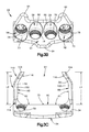
- FIG. 12A is a perspective view of an intervertebral implant frame constructed in accordance with another embodiment, the frame including first and second arms that each include a crimp member configured as a crimp tab disposed within a window defined by the arm;
- FIG. 12B is a top plan view of the frame shown in FIG. 12A ;
- FIG. 13A is a perspective view of an intervertebral implant frame constructed in accordance with another embodiment, the frame including first and second arms that each include at least one crimp member configured as a crimp tab;
- FIG. 13B is a top plan view of the frame shown in FIG. 13A ;
- FIG. 14A is a perspective view of an actuation instrument configured as a crimping instrument constructed in accordance with an embodiment, the instrument including gripping members that are configured to crimp the crimp members of the frames shown in FIGS. 10A and 11A ;
- FIG. 14B is a detailed top plan view of the gripping members of the instrument shown in FIG. 14A , and an intervertebral implant disposed between the gripping members;
- FIG. 14C is a top plan view of the gripping members illustrated in FIG. 14B , shown in a crimped position, whereby the crimp members are crimped onto a spacer body of the intervertebral implant so as to secure the arms to the intervertebral implant;
- FIG. 14D is a detailed view of gripping members of a crimping instrument constructed in accordance with another embodiment, the gripping members including a beaked protrusion configured to crimp the crimp members of the frame shown in FIG. 12A ;
- FIG. 15A is a perspective view of an intervertebral implant frame constructed in accordance with another embodiment, the frame defining a four walled structure;
- FIG. 15B is a top plan view of the frame shown in FIG. 15A ;
- FIG. 16A is a perspective view of a spacer body drill guide constructed in accordance with an embodiment, the drill guide including a clamp, and a cradle that is configured to mate with and support the clamp;
- FIG. 16B is a perspective view of the clamp shown in FIG. 16A ;
- FIG. 16C is a perspective view of the clamp being mounted to the cradle
- FIG. 16D is a perspective view of the clamp after it has been mounted to the cradle
- FIG. 16E is a perspective view of a drill bit being inserted into drill guide apertures defined by the clamp to thereby form clearance channels in the spacer body;
- FIG. 16F is a perspective view of a spacer body after the clearance channels have been formed using the drill guide shown in FIG. 16A .
- a superior vertebral body 10 a defines a first or superior vertebral surface 14 a of an intervertebral space 18
- an adjacent second or inferior vertebral body 10 b defines an inferior vertebral surface 14 b of the intervertebral space 18
- the intervertebral space 18 is disposed between or otherwise defined by the vertebral bodies 10 a and 10 b .
- the vertebral bodies 10 a and 10 b can be anatomically adjacent vertebral bodies, or can remain after a portion of bone has been removed.
- the intervertebral space 18 can be disposed anywhere along the spine as desired, including at the lumbar, thoracic, and cervical regions of the spine.
- the intervertebral space 18 is illustrated after a discectomy, whereby the disc material has been removed or at least partially removed to prepare the intervertebral space 18 to receive an intervertebral implant 22 that can achieve height restoration.
- the intervertebral implant 22 can be affixed to the superior and inferior vertebral bodies 10 a and 10 b with respective fixation elements 62 .
- the intervertebral implant 22 and the fixation elements 62 together define an intervertebral implant assembly 24 .
- the intervertebral implant 22 is described herein as extending horizontally along a longitudinal direction “L” and lateral direction “A”, and vertically along a transverse direction “T”.
- the terms “lateral,” “longitudinal,” and “transverse” are used to describe the orthogonal directional components of various components. It should be appreciated that while the longitudinal and lateral directions are illustrated as extending along a horizontal plane, and that the transverse direction is illustrated as extending along a vertical plane, the planes that encompass the various directions may differ during use.
- the transverse direction T extends vertically generally along the superior-inferior (or caudal-cranial) direction, while the horizontal plane defined by the longitudinal direction L and lateral direction A lies generally in the anatomical plane defined by the anterior-posterior direction, and the medial-lateral direction, respectively.
- the directional terms “vertical” and “horizontal” are used to describe the intervertebral implant 22 and its components as illustrated merely for the purposes of clarity and illustration.
- the vertebral surfaces 14 a and 14 b of the vertebral bodies 10 a and 10 b can define a geometrical centroid M that is generally located at an anterior-posterior midpoint between an anterior end and a posterior end of the surfaces 14 a and 14 b .
- the intervertebral implant 22 is configured to be disposed or otherwise implanted in the intervertebral space 18 such that a portion of the intervertebral implant 22 is located on a posterior side of a medial lateral plane that intersects the centroid M, and a portion of the intervertebral implant 22 is located on an anterior side of the medial lateral plane that intersects the centroid M.
- Such a configuration can ensure that the height restoration of the intervertebral space 18 remains relatively unchanged over time.
- the intervertebral implant 22 includes an intervertebral implant frame 26 and a spacer body 30 that is retained by the frame 26 .
- the intervertebral implant 22 defines a proximal end P and a distal end D.
- the frame 26 may be made from any biocompatible material, such as TAN alloy, or PEEK.
- the spacer body 30 may be composed of a synthetic material such as PEEK or a graft substitute such a tricalcium phosphate or hydroxyapatite.
- the spacer body 30 may also be composed of a bone graft such as allograft bone, autograft bone or xenograft bone.
- the frame 26 is configured to be attached to various bone graft spacer body footprint geometries, which may or may not conform to the internal footprint of the frame 26 .
- the frame 26 includes a support member 34 , a first arm 38 that extends from the support member 34 , and a second arm 42 that extends from the support member 34 .
- the first and second arms 38 and 42 are flexible arms that extend from opposed ends of the support member 34 such that the support member 34 , the first arm 38 , and the second arm 42 together create a three wall structure that retains and secures the spacer body 30 to the frame 26 .
- the support member 34 includes a body 46 that defines an inner surface 50 , an outer surface 54 , and at least one, such as two or such as four, fixation element receiving apertures 58 that extend through the body 46 from the outer surface 54 to the inner surface 50 .
- Each fixation element receiving aperture 58 is configured to receive a respective fixation element, such as fixation element 62 shown in FIGS. 4A and 4B . While the fixation elements 62 are illustrated as screws, it should be appreciated that the fixation elements 62 may also be nails or any other fixation element configured to attach the intervertebral implant 22 to the first and second vertebral bodies 10 a and 10 b .
- the support member 34 can further include at least one, such as three tabs 64 that extend transversely from the body 46 .
- the tabs 64 may sit on an anterior side of the vertebral bodies and prevent over-insertion of the frame 26 into the intervertebral space 18 .
- the support member 34 includes two superior tabs 64 and one inferior tab 64 that are each configured to sit flush or slightly proud of an anterior surface of the vertebral bodies depending on the patient's spinal anatomy and/or site preparation. It should be appreciated, however, that the support member 34 can include other configurations for the tabs 64 .
- the support member 34 can include a single superior tab 64 and two inferior tabs 64 .
- two of the fixation element receiving apertures 58 are inner apertures 66 that extend through the body 46 at a downward angle relative to the insertion direction I
- two of the fixation element receiving apertures 58 are outer apertures 70 that extend through the body 46 at an upward angle relative to the insertion direction I.
- the inner apertures 66 are configured to receive respective fixation elements, such as fixation element 62 shown in FIGS. 4A and 4B , to thereby attach the intervertebral implant 22 to the inferior vertebral body 10 b
- the outer apertures 70 are configured to receive respective fixation elements 62 to thereby attach the intervertebral implant 22 to the superior vertebral body 10 a .
- the inner apertures 66 can extend through the body 46 at an upwards angle and the outer apertures 70 can extend through the body 46 at a downwards angle, as desired.
- the support member 34 can define any number of fixation element receiving apertures 58 as desired.
- the apertures 58 each define internal threads 78 .
- the internal threads 78 are configured to engage external threads 80 defined by a head 82 of the respective fixation element 62 that is received within the apertures 58 .
- the apertures 58 can be void of threads as desired.
- the orientation of the apertures 58 may be configured such that the fixation elements that are received by the apertures 58 may have an insertion variance of +/ ⁇ 5 degrees and do not allow toggling or settling. Once fully received, the fixation elements may lock to the frame 26 to thereby increase the surgeon's reassurance of good screw trajectories and can act as a safety by preventing possibilities of over-insertion during implantation.
- support member 34 can include a retention member 73 that extends from the inner surface 50 .
- the retention member 73 is configured to help retain the spacer body 30 when the spacer body is being supported by the frame 26 .
- the retention member 73 is illustrated as a spike though it should be appreciated, that the retention member 73 can have other configurations.
- the retention member 73 can be configured as a blade.
- the first arm 38 and the second arm 42 each extend from the support member 34 and define a first distal terminal end 83 and a second distal terminal end 84 , respectively.
- the first and second arms 38 and 42 each define gripping portions and support portions.
- the gripping portions are configured to retain the spacer body 30 while the support portions are configured to support the vertebral bodies 10 a and 10 b relative to each other.
- the gripping portions and the support portions can be a single structure or the support portions can be separate structures that extend from the gripping portions.
- the arms 38 and 42 can be radiolucent so as to increase fluoroscopy visibility.
- the first arm 38 includes a first inner spacer contacting surface 88 and the second arm 42 includes a second inner spacer contacting surface 92 that is spaced from the first inner spacer contacting surface 88 along a first direction, such as the lateral direction A.
- the inner surface of the support member 34 , the first inner spacer contacting surface 88 , and the second inner spacer contacting surface 92 together define a void 94 that is configured to receive and grip the spacer body 30 .
- the terminal ends 83 and 84 are spaced apart from the support member along a second direction, such as the longitudinal direction L that is substantially perpendicular to the first direction so as to define first and second lengths L 1 and L 2 , respectively of the first and second arms 38 and 42 .
- the first and second arms 38 and 42 are sized such that the first and second lengths L 1 and L 2 are each greater than a length L 3 defined between an anterior end E of the inferior vertebral body 10 b and the centroid M of the surface 14 b of the inferior vertebral body 10 b , as shown in FIG. 1C . It should be appreciated, that the first and second arms 38 and 42 can also be sized such that the first and second lengths L 1 and L 2 are greater than a length defined between an anterior end of the superior vertebral body 10 a and a centroid of the surface 14 a of the superior vertebral body 10 a .
- the first and second lengths L 1 and L 2 may be between about 3.5 mm and about 12 mm, between about 6.0 mm and about 10 mm, and preferably about 9.5 mm.
- the support member 34 , the first arm 38 , and the second arm 42 extend around at least 51% of the spacer body 30 , and preferably around at least 80% of the spacer body 30 .
- the flexible arms 38 and 42 can have a transverse height and a lateral width that at least partially define a cross-sectional area of the arms 38 and 42 .
- the arms 38 and 42 can have a cross-sectional area that may vary so long as the arms 38 and 42 are capable of elastically deforming or flexing to thereby allow the frame 26 to receive the spacer body and subsequently apply a retention force to the spacer body 30 after the frame 26 has received the spacer body 30 .
- the arms 38 and 42 are configured to elastically flex laterally outwardly away from each other, or otherwise elastically deform from a first position to a second flexed position to allow the frame 26 to receive the spacer body 30 .
- the first position can be a relaxed position of the arms 38 and 42 or a flexed position of the arms 38 and 42 that is outwardly flexed with respect to a relaxed position. At least respective portions of the arms 38 and 42 , such as contact locations 320 and 324 (see FIG. 6E ), are further spaced from each other in the second position than when in the first position. Once the spacer body 30 is disposed between the arms 38 and 42 , the arms 38 and 42 may flex inwardly toward each other to a third or engaged position whereby the arms 38 and 42 engage the spacer body 30 so as to secure the frame 26 to the spacer body 30 as shown in FIG. 2 .
- the third position can be outwardly flexed with respect to the first position, and can be substantially equal to the first position.
- the respective portions of the arms 38 and 42 can be further spaced from each other when in the third position with respect to the first position, or the respective portions of the arms 38 and 42 can be spaced from each other when in the third position a distance substantially equal to the distance that the respective portions of the arms 38 and 42 are spaced when in the first position.
- at least respective portions of the arms 38 and 42 are spaced apart a distance equal to or greater than (or no less than) the distance that the arms 38 and 42 are spaced when in the first position.
- At least respective portions of the arms 38 and 42 can be spaced apart a distance when in the engaged position that is less than the distance that the respective portions of the arms 38 and 42 are spaced apart when in the first position.
- the first and second arms 38 and 42 extend from the support member 34 such that the first and second arms 38 and 42 are angled toward each other so as to push the spacer body 30 toward the other of the first and second arms 38 and 42 and toward the support member 34 .
- the inner surface of the support member 34 and the first inner spacer contacting surface 88 form an angle ⁇ 1 that is less than 90 degrees
- the inner surface 50 of the support member 34 and the second inner spacer contacting surface 92 form an angle ⁇ 2 that is less than 90 degrees.
- ⁇ 1 and ⁇ 2 are each about 88 degrees, though it should be appreciated that ⁇ 1 and ⁇ 2 may be any angle as desired, and may be different angles with respect to each other.
- each arm 38 and 42 includes a substantially straight portion 100 that extends from the support member 34 , and a distal bent or angled portion 104 that extends from a distal end of the straight portion 100 toward the other of the bent portions 104 such that the bent portions 104 are configured to contact a distal surface of the spacer body 30 .
- the bent portions 104 at least partially wrap around the spacer body 30 to thereby prevent the spacer body 30 from separating from the frame 26 after the spacer body 30 has been retained by the frame 26 .
- each arm 38 and 42 can include at least one, such as a plurality of retention members 116 that extend out from the first and second inner spacer contacting surfaces 88 and 92 .
- the retention members 116 define teeth that extend out of the bent portions 104 so as to form a column of teeth on each bent portion 104 .
- the retention members 116 are configured to engage the spacer body 30 when the frame 22 is retaining the spacer body 30 to thereby ensure that the spacer body 30 remains retained by the frame 22 . It should be appreciated, however, that the retention member 116 can have any configuration as desired, so long as the retention member 116 is capable of engaging the spacer body 30 .
- the retention members 116 can be spikes that extend from the inner surfaces 88 and 92 at an angle, elongate blades, or even punches that can be punched into the spacer body 30 by an individual after the spacer body 30 is disposed in the frame 26 .
- each arm 38 and 42 may be configured to assist in bearing compressive loads by the vertebral bodies 10 a and 10 b to thereby mitigate subsidence and settling.
- each arm 38 and 42 defines a respective distal portion 110 and a respective proximal portion 114 .
- the distal portions 110 are spaced apart from the proximal portions 114 along the longitudinal direction L such that when the frame 26 is disposed in the intervertebral space 18 , the distal portions 110 are on the posterior side of the centroid M of the surface 14 b of the inferior vertebral body 10 b , and the proximal portions 114 are on the anterior side of the centroid M of the surface 14 b of the inferior vertebral body 10 b .
- Each distal portion 110 defines a superior vertebral body contacting surface 118 and an inferior vertebral body contacting surface 122 .
- each proximal portion 114 defines a superior vertebral body contacting surface 126 and an inferior vertebral body contacting surface 130 . Because of the length of the arms 38 and 42 and because of the transverse height of the arms 38 and 42 at their distal and proximal portions, the frame 26 can bear compressive loads from the vertebral bodies if the spacer body 30 were to subside.
- the arms 38 and 42 may be configured to conform to the lordotic curve of the spine and in particular of the intervertebral space 18 in which the frame 26 is to be disposed.
- a line drawn between the superior vertebral body contacting surfaces 118 and 126 of the first arm 38 forms an angle that is between about 0 degrees and about ⁇ 5 degrees with respect to the insertion direction I
- a line drawn between the inferior vertebral body contacting surfaces 122 and 130 of the first arm forms a line that is between about 0 degrees and about 5 degrees with respect to the insertion direction I.
- a line drawn between the superior vertebral body contacting surfaces 118 and 126 of the second arm 42 forms an angle that is between about 0 degrees and about ⁇ 5 degrees with respect to the insertion direction
- a line drawn between the inferior vertebral body contacting surfaces 122 and 130 of the second arm 42 forms an angle that is between about 0 degrees and about 5 degrees with respect to the insertion direction I.
- the lines drawn between the superior vertebral body contacting surfaces 118 and 126 , and between the inferior vertebral body contacting surfaces 122 and 130 can be any angle as desired.
- the lines may be parallel to each other. Therefore, it can be said that a first plane is defined by the superior vertebral body contacting surfaces, and a second plane is defined by the inferior vertebral body contacting surfaces. The first plane and the second plane can be parallel to each other or converge toward each other.
- each arm 38 and 42 further includes a superior cut-out 140 and an inferior cut-out 144 to thereby provide visual access to the superior vertebral body 10 a and to the inferior vertebral body 10 b respectively when the frame 26 is disposed in the intervertebral space 18 .
- the cut-outs 140 and 144 are each disposed between the proximal portions 114 and distal portions 110 of the first and second arms 38 and 42 .
- the superior cut-outs 140 extend laterally through an upper portion of the arms 38 and 42 so as to define upper curved recesses 148 in the straight portions 100 of the arms 38 and 42 .
- the inferior cut-outs 144 extend laterally through a lower portion of the arms 38 and 42 so as to define lower curved recesses 152 in the arms 38 and 42 . It should be appreciated that the superior and inferior cut-outs 140 and 144 can have other configurations as desired. For example, the cut-outs 140 and 144 can define rectangular channels that extend through the arms 38 and 42 .
- each arm 38 and 42 can further include a window 156 that extends laterally through the straight portions 100 of the arms 38 and 42 between the superior and inferior cut-outs 140 and 144 .
- the windows 156 are configured to provide visual access to the spacer body 30 through the first and second arms 38 and 42 when the frame 26 is retaining the spacer body 30 .
- the windows 156 are oval shaped and elongate along the longitudinal direction L. It should be appreciated, however, that the windows 156 can have any shape as desired. For example, the windows 156 can also be rectangular shaped.
- each arm 38 and 42 includes an engagement member 170 that is configured to receive a first and a second external expansion force, respectively, from an expansion instrument prior to insertion of the spacer body 30 into the void 94 such that at least one of the first and second arms 38 and 42 elastically expands or elastically flexes with respect to the other of the first and second arms 38 and 42 in response to the expansion forces.
- the engagement members 170 each define a dove-tailed slot 174 that defines an opening 178 at its distal end such that the expansion instrument can engage the dove-tailed slot 174 in a direction that is opposite to the insertion direction I of the frame 26 . As shown in FIG.
- the dove-tailed slots 174 are wider at the openings 178 and taper as they extend proximally.
- the wider openings 178 provide a guide for the expansion instrument to engage the engagement members 170 .
- the dove-tailed slots 174 each include a pair of opposed recesses 182 that define angled engagement surfaces 186 . It should be appreciated, however, that the engagement members 170 can have any configuration as desired so long as they can receive respective expansion forces.
- the spacer body 30 that is received within the frame 26 is preferably made from a bone graft material such as allograft bone, autograft bone, or xenograft bone, for example.
- the spacer body 30 can include cancellous bone 190 that is at least partially surrounded by cortical bone 194 . It should be appreciated, however, that the spacer body 30 can be made from only cancellous bone 190 or from only cortical bone 194 .
- the spacer body can alternatively be made from a synthetic material.
- the spacer body 30 is sized and dimensioned to fit within the frame 26 .
- the spacer body may have a lateral width of between about 10 mm and about 16 mm, a longitudinal length of between about 10 mm and 17 mm, and a transverse height that is between about 5 mm and about 12 mm.
- the outer footprint of the spacer body 30 can vary and the frame 26 may still be able to retain the spacer body 30 .
- the frame 26 or at least the arms 38 and 42 are configured to retain a first spacer body 30 having a first maximum width, a first outer footprint, or a first cross-sectional dimension, and a second spacer body having a second maximum width, a second outer footprint, or a second cross-sectional dimension that is different than those of the first spacer body 30 . Therefore, the frame 26 and in particular the arms 38 and 42 can retain spacer bodies 30 that are made from bone shaped by the surgeon and not just spacer bodies 30 that are machined to have specific dimensions prior to insertion into the frame 26 .
- the spacer body 30 can define a superior or upper or outer bone engaging surface 200 and an opposed inferior or lower or outer bone engaging surface 204 .
- the surfaces 200 and 204 are configured to engage the superior and inferior surfaces 14 a and 14 b , respectively of the vertebral bodies 10 a and 10 b .
- the spacer body 30 can further define side surfaces 208 that are configured to be engaged by the first and second inner spacer contacting surfaces of the first and second arms 38 and 42 to thereby retain the spacer body 30 within the frame 26 .
- the spacer body 30 can be coupled to the frame 26 using an actuation instrument 210 that is configured as an expansion instrument.
- the instrument 210 , the frame 26 , and in some cases the spacer body 30 can together define an intervertebral implant system 214 .
- the expansion instrument 210 includes a grip 212 and a handle 213 .
- the grip 212 is configured as an expansion grip and is configured to apply the first and second expansion forces to the engagement members 170 of the first and second arms 38 and 42 .
- the first and second expansion forces will elastically expand the first and second arms 38 and 42 of the frame 26 to thereby allow the spacer body 30 to be received by the void 94 of the frame 26 .
- the instrument 210 includes a first arm 220 that is configured to releasably couple to the first arm 38 of the frame 26 , and a second arm 224 that is rotatably coupled to the first arm 220 at a first pivot 228 and is configured to releasably couple to the second arm 42 of the frame 26 .
- the first and second arms 220 and 224 are configured as expansions arms.
- the first and second expansion arms 220 and 224 are pivotally coupled to each other at the first pivot 228 such that rotation of the first and second expansion arms 220 and 224 about the first pivot 228 causes the first and second arms 38 and 42 of the frame 26 to elastically flex away from each other when the instrument 210 is coupled to the frame 26 .
- the instrument 210 is configured to have a first position or configuration whereby the instrument 210 can be coupled to the frame 26 , and a second position or configuration whereby the instrument 210 is applying expansion forces to the arms 38 and 42 of the frame 26 so that the frame can receive the spacer body 30 .
- each expansion arm 220 and 224 includes a handle portion 232 that extends proximally from the first pivot 228 and a gripping portion 236 that extends distally from the first pivot 228 .
- the handle portions 232 define the handle 213
- the gripping portions 236 define the grip 212 .
- the handle portions 232 are configured to be gripped by an individual such that the handle portions 232 can be squeezed or otherwise moved toward each other.
- the expansion instrument 210 can further include a handle locking mechanism 240 that is configured to lock the handle portions 232 relative to each other after the handle portions 232 have been moved toward each other.
- the locking mechanism 240 includes a threaded shaft 244 and a nut 248 .
- the nut 248 can be threaded along the shaft 244 to thereby lock the handle portions 232 relative to each other.
- the locking mechanism 240 can include other configurations, as desired.
- the locking mechanism 240 can have a ratchet configuration.
- each gripping portion 236 is configured to expand the frame arms as the handle portions 232 are moved toward each other.
- Each gripping portion 236 includes an extension member 250 that extends distally from the first pivot 228 , and a gripping member 254 that is pivotally coupled to a distal end of the extension member 250 at a second pivot 258 .
- Each gripping member 254 includes an engagement member 262 that is configured to engage respective engagement members 170 of the first and second arms 38 and 42 of the frame 26 . As shown in FIG.
- the engagement members 262 are dove-tailed members 266 that are opposed to each other and are configured to mate with the dove-tailed slots of the first and second arms 38 and 42 to thereby couple the expansion instrument 210 to the frame 26 .
- each dove-tailed member 266 includes a pair of transversely opposed protrusions 280 that each define an angled engagement surface 284 that is configured to abut or otherwise contact a respective angled engagement surface 186 of the slots 174 when the engagement members 262 are mated with the engagement members 170 .
- the engagement members 262 can have other configurations as desired. For example, the engagement members 262 and the engagement members 170 can be reversed.
- each engagement member 262 defines a tapered lead-in portion 270 that allows the engagement members 262 to easily be guided into the openings 178 of the engagement members 170 . Therefore, the expansion instrument 210 can easily be coupled to the frame 26 along a direction that is opposite the insertion direction I. That is, if the frame 26 is stationary, the expansion instrument 210 can be coupled to the frame 26 by translating the instrument 210 along a direction that is opposite the insertion direction I.
- each gripping member 254 includes a pair of stops 300 that extend proximally toward the extension member 250 and are spaced apart from the extension member 250 . As the gripping member 254 rotates about the second pivot 258 the stops 300 will limit the rotation by contacting the extension member 250 . Therefore, the angular range in which the gripping members 254 can rotate about the second pivots 258 will depend on the distance in which the stops 300 are spaced apart from the extension members 250 .
- each gripping portion 236 further includes a biasing member 304 that is configured to bias the gripping members 254 toward each other.
- the biasing members 304 are leaf springs 308 that are coupled to the extension members 250 and urge against an outer surface of the gripping members 304 .
- the expansion instrument 210 can more easily and more predictably be coupled to the frame 26 .
- the biasing members 304 can have other configurations as desired.
- the expansion instrument 210 is coupled to the frame 26 by placing the engagement members 262 of the instrument 210 distal to the engagement members 170 of the frame 26 .
- the engagement members 262 will engage the engagement members 170 to thereby couple the frame 26 to the instrument 210 such that the second pivots 258 of the instrument 210 abut an outer surface of the flexible arms 38 and 42 proximate to the support member 34 .
- the extension member 250 of the first expansion arm 220 will rotate counterclockwise about the first pivot 228 and the gripping member 254 of the first expansion arm 220 will rotate clockwise about the second pivot 258 .
- the extension member 250 of the second expansion arm 224 will rotate clockwise about the first pivot 228 and the gripping member 254 of the second expansion arm 224 will rotate counterclockwise about the second pivot 258 .
- first and second inner spacer contacting surfaces 88 and 92 of the first and second arms 38 and 42 can define respective first and second respective contact locations 320 and 324 , and at least one of the first and second arms 38 and 42 is flexible so as to be movable between a first position, whereby the frame 26 defines a first distance d 1 that extends along the lateral direction A between the first and second contact locations 320 and 324 , and a second position, whereby the frame 26 defines a second distance d 2 that extends along the lateral direction A between the first and second contact locations 320 and 324 .
- the first and second contact locations 320 and 324 can be located anywhere along the arms 320 and 324 so long as they remain the same when the first and second distances are measured.
- the second distance d 2 is greater than the first distance d 1 such that when in the second position, the void 94 defines a cross-sectional dimension that is greater than that of the spacer body 30 such that the void 94 is sized to receive the spacer body 30 .
- the arms 38 and 42 are elastically flexed, at least one of the arms 38 and 42 is biased toward the first position. Therefore, when the handle portions 232 of the instrument 210 are released, the arms 38 and 42 will flex back to a third position, and when in the third position, the frame 26 defines a third distance d 3 that extends along the lateral direction A between the first and second contact locations 320 and 324 and is less than the second distance d 2 (See FIG.
- an intervertebral implant system 350 can include an intervertebral implant frame 426 , and an actuation instrument 428 that is also configured as an expansion instrument.
- the frame 426 includes a support member 434 , a first arm 438 that extends from the support member 434 , and a second arm 442 that extends from the support member 434 .
- the first and second arms 438 and 442 are flexible arms and are configured to elastically flex away from each other so that the frame 426 can receive a spacer body 30 .
- the support member 434 , the first arm 438 , and the second arm 442 are similar to the support member 34 , the first arm 38 , and the second arm 42 shown in FIG. 3A , and include like structure unless otherwise described.
- each of the first and second arms 438 and 442 includes a straight portion 446 and a bent portion 450 that extends from a distal end of the straight portion 446 at angle toward the other of the bent portions 450 .
- Each arm 438 and 442 further includes an engagement member 454 that defines a slot 458 that extends through the respective arm 438 and 442 .
- the slots 458 extend through the straight portions 446 at substantially the same angle in which the bent portions 450 extend from the distal end of the straight portions 446 .
- the slots 458 extend through the straight portions 446 and into a cavity 460 defined by the bent portions 450 .
- Each bent portion 450 further includes a retention bump 461 .
- the bumps 461 are configured to provide a tactile feedback indicating that the expansion instrument 428 is coupled to the arms 438 and 442 .
- the expansion instrument 428 can include a pair of removable clips 470 that are configured to engage the slots 458 defined by the arms 438 and 442 by translating the clips 470 distally or along a direction that has a directional component that is the same as the insertion direction I.
- each clip 470 can be a substantially straight elongate member 474 having an engagement member 476 that is defined by a pair of elongate cantilevered beams 478 at its distal end that are separated by a recess 482 .
- An outer beam 478 can include a recess 479 that is configured to receive the retention bump 461 and provide an indication that the clips 470 are properly coupled to the arms 438 and 442 . As shown in FIG.
- each clip 470 can be attached to a respective arm 438 and 442 by inserting one of the cantilevered beams 478 of a respective clip 470 into a slot 458 of the respective arms 438 and 442 .
- the cantilevered beam 478 that is inserted into the slot 458 will be received by the cavity 460 defined by the bent portion 450 .
- the clips 470 extend out from the arms 438 and 442 at an angle such that the clips 470 diverge from each other as they extend proximally.
- the cantilevered beams 478 apply an expansion force to the engagement members 454 or at least to the bent portions 450 such that the arms 438 and 442 elastically flex away from each other. While flexed, the frame 426 can receive the spacer body 30 .
- the arms 438 and 442 will apply a retention force to the spacer body 30 to thereby retain the spacer body 30 in the frame 426 .
- an intervertebral implant system 522 can include an intervertebral implant frame 526 , and an actuation instrument 528 that is configured as an expansion instrument.
- the frame 526 includes a support member 534 , a first arm 538 that extends from the support member 534 , and a second arm 542 that extends from the support member 534 .
- the first and second arms 538 and 542 flexible arms and are configured to elastically flex away from each other so that the frame 526 can receive a spacer body 30 .
- the support member 534 , the first arm 538 , and the second arm 542 are similar to the support member 34 , the first arm 38 , and the second arm 42 shown in FIG. 3A , and include like structure unless otherwise described.
- each of the first and second arms 538 and 542 includes a straight portion 546 and a bent portion 550 that extends from a distal end of the straight portion 546 at angle toward the other of the bent portions 550 .
- Each arm 538 and 542 further includes an engagement member 554 that defines a slot 558 that extends through the respective arm 538 and 542 .
- the slots 558 extend through the bent portions 550 along a direction that is opposite the insertion direction I.
- the slots 558 extend into a cavity 560 that is defined by each straight portion 546 .
- Each straight portion 546 further includes a retention bump 561 .
- the bumps 561 are configured to provide a tactile feedback indicating that the expansion instrument 528 is coupled to the arms 538 and 542 .
- the expansion instrument 528 can include a pair of removable clips 570 that are configured to engage the slots 558 defined by the arms 538 and 542 by translating the clips 570 proximally or along a direction that is opposite to the insertion direction I.
- each clip 570 includes a handle portion 574 and a gripping portion 578 that extends distally from the handle portion 574 .
- Each gripping portion 578 includes a body 582 and an engagement member 584 that extends out from the body 582 .
- each engagement member 584 defines a proximally extending protrusion 586 that is spaced from the 582 such that a recess 588 is defined between the protrusion 586 and body 582 .
- Each gripping portion 578 further includes a shoulder 590 that extends out from the body 582 and is configured to abut the arms 538 and 542 proximate to the support member 526 when the clip 570 is coupled to the frame 526 .
- Each clip 570 further includes a recess 579 that is configured to receive the retention bump 561 and provide an indication that the clips 570 are properly coupled to the arms 538 and 542 .
- each clip 570 can be attached to a respective arm 538 and 542 by inserting the protrusion 586 of a respective clip 470 into a slot 558 of a respective arm 538 and 542 . The protrusion 586 will be received by the cavity 560 defined by the straight portion 546 .
- the clips 570 extend out from the arms 538 and 542 such that the handle portions 574 are proximal to the front of the frame 526 and the shoulders 590 are abutting the arms 538 and 542 proximate to the support member 526 as shown in FIG. 8B .
- clips 570 rotate about the shoulders 590 and the protrusions 586 apply an expansion force to the engagement members 554 or to at least the straight portions 546 such that the arms 538 and 542 elastically flex away from each other. While flexed, the frame 526 can receive the spacer body 30 .
- the arms 538 and 542 will apply a retention force to the spacer body 30 to thereby retain the spacer body 30 in the frame 526 .
- frame 26 and instrument 210 can include any of the engagement members 170 , 262 , 454 , 476 , 554 , and 584 so long as the engagement members of the frame 26 can mate with the engagement members of the instrument 210 to thereby releasably couple the frame 26 to the instrument 210 .
- an intervertebral implant frame 626 can include a support member 634 , a first arm 638 that extends from the support member 634 , and a second arm 642 that extends from the support member 634 .
- the first and second arms 638 and 642 are flexible arms and are configured to elastically flex away from each other so that the frame 626 can receive a spacer body 30 .
- the support member 634 , the first arm 638 , and the second arm 642 are similar to the support member 34 , the first arm 38 , and the second arm 42 shown in FIG. 3A , and include like structure unless otherwise described.
- each of the first and second arms 638 and 642 includes a straight portion 646 and a bent portion 650 that extends from a distal end of the straight portion 646 at angle toward the other of the bent portions 650 .
- Each arm 638 and 642 further includes an expansion member 654 that extends out from the arm at angle.
- each expansion member 654 extends out from the proximal end of the bent portion 650 and includes a handle portion 660 that is spaced apart from the straight portion 646 .
- the expansion members 654 can extend proximally such that handle portions 660 are proximal to the arms 638 and 642 to thereby provide more lavage. Once the frame 626 has been coupled to the spacer body 30 , the expansion members 654 can be broken off and removed from the frame 626 .
- the frame can be configured to have portions of the frame arms crimped toward the spacer body to thereby retain the spacer body.
- the frame is capable of receiving the spacer body without flexing the arms of the frame away from each other. The spacer body will then be retained by the frame by crimping the arms toward the spacer body to thereby provide a retention force to the spacer body.
- an intervertebral implant frame 726 includes a support member 734 , a first arm 738 that extends from the support member 734 , and a second arm 742 that extends from the support member 734 .
- the first and second arms 734 and 738 are crimpable arms such that the frame 726 is configured to have a first initial position in which the spacer body 30 can be disposed between the arms 738 and 742 , and a second crimped or engaged position in which the arms 738 and 742 are crimped toward each other to thereby apply a retention force to the spacer body 30 .
- the support member 734 , the first arm 738 , and the second arm 742 are similar to the support member 34 , the first arm 38 , and the second arm 42 shown in FIG. 3A , and include like structure unless otherwise described.
- the first and second arms 738 and 742 are configured to be crimped rather than flexed.
- the arms 738 and 742 include first and second inner spacer contacting surfaces 744 and 746 , respectively that are configured to contact and retain the spacer body 30 . That is, the inner surface of the support member 734 , the first inner spacer contacting surface 744 and the second inner spacer contacting surface 746 together define a void 748 that is configured to receive the spacer body 30 .
- Each arm 738 and 742 further includes a substantially straight portion 750 and a crimp member 752 that extends distally from the straight portion 748 . As shown, the crimp members 752 are each coupled to the straight portions 750 by a hinge 756 . In the illustrated embodiment, the hinges 756 define transverse bending grooves 758 formed in the inner spacer contacting surfaces 744 and 746 .
- the frame 726 can receive the spacer body 30 within the void 748 without expanding the arms 738 and 742 away from each other. Though it should be appreciated some expanding may occur.
- the first crimp member 752 of the first arm 738 can be rotated about the first hinge 756 such that the first crimp member 752 is bent toward the second arm 742 .
- the second crimp member 752 of the second arm 742 can be rotated about the second hinge 756 such that the second crimp member 752 is bent toward the first arm 738 .
- each arm 738 and 742 can further include a retention member 760 that extends from the first and second inner spacer contacting surfaces 744 and 746 , respectively.
- the retention members 760 are configured to engage the spacer body 30 to thereby prevent migration of the spacer body 30 from the frame 726 .
- an intervertebral implant frame 826 can include more than two crimp members.
- the frame 826 includes a support member 834 , a first arm 838 that extends from the support member 834 , and a second arm 842 that extends from the support member 834 .
- the first and second arms 838 and 842 are crimpable arms such that the frame 826 is configured to have a first initial position in which the spacer body 30 can be disposed between the arms 838 and 842 , and a second crimped or engaged position in which the arms 838 and 842 are crimped toward each other to thereby apply a retention force to the spacer body 30 .
- the support member 834 , the first arm 838 , and the second arm 842 are similar to the support member 34 , the first arm 38 , and the second arm 42 shown in FIG. 3A , and include like structure unless otherwise described.
- the first and second arms 838 and 842 are configured to be crimped rather than flexed.
- the arms 838 and 842 include first and second inner spacer contacting surfaces 844 and 846 , respectively that are configured to contact and retain the spacer body 30 . That is, the inner surface of the support member 834 , the first inner spacer contacting surface 844 and the second inner spacer contacting surface 846 together define a void 848 that is configured to receive the spacer body 30 .
- Each arm 838 and 842 further includes a first crimp member 850 and a second crimp member 852 that extends distally from the first crimp member 850 .
- the first arm 838 can include a first crimp member 850 and a third crimp member 852 of the frame 826
- the second arm 842 can include a second crimp member 850 and a fourth crimp member 852 of the frame 826
- the first crimp member 850 and the second crimp member 850 are each coupled to the support member 834 by first and second hinges 856 respectively
- the third and fourth crimp members 852 are coupled to the first crimp members 850 by third and fourth hinges 860 respectively.
- the hinges 856 and 860 define transverse bending grooves 864 formed in the outer surfaces of the first and second arms 838 and 842 .
- the frame 826 can receive the spacer body 30 within the void 848 without expanding the arms 838 and 842 away from each other. Though it should be appreciated some expanding may occur.
- the first crimp member 850 and the second crimp member 852 of the first arm 838 can be rotated about the first and second hinges 856 and 860 respectively such that the crimp members 850 and 852 are bent toward the second arm 842 .
- the first crimp member 850 and the second crimp member 852 of the second arm 842 can be rotated about the first and second hinges 856 and 860 respectively such that the crimp members 850 and 852 are bent toward the first arm 838 .
- each arm 838 and 842 can further include a retention member 868 that extends from the first and second inner spacer contacting surfaces 844 and 846 , respectively.
- the retention members 868 are configured to engage the spacer body 30 to thereby prevent migration of the spacer body 30 from the frame 826 .
- an intervertebral implant frame 926 can include crimp members that define crimping tabs.
- the frame 926 includes a support member 934 , a first arm 938 that extends from the support member 934 , and a second arm 942 that extends from the support member 934 .
- the first and second arms 938 and 942 are crimpable arms such that the frame 926 is configured to have a first initial position in which the spacer body 30 can be disposed between the arms 938 and 942 , and a second crimped or engaged position in which the arms 938 and 942 are crimped toward each other to thereby apply a retention force to the spacer body 30 .
- the support member 934 , the first arm 938 , and the second arm 942 are similar to the support member 34 , the first arm 38 , and the second arm 42 shown in FIG. 3A , and include like structure unless otherwise described.
- the first and second arms 938 and 942 are configured to be crimped rather than flexed.
- the arms 938 and 942 include first and second inner spacer contacting surfaces 944 and 946 , respectively that are configured to contact and retain the spacer body 30 . That is, the inner surface of the support member 934 , the first inner spacer contacting surface 944 and the second inner spacer contacting surface 946 together define a void 948 that is configured to receive the spacer body 30 .
- Each arm 938 and 942 further includes a substantially straight portion 950 , a bent portion 951 extending from a distal end of the straight portion 950 , and a crimp member 952 that is formed in the straight and bent portion 950 and 951 .
- the crimp members 952 each define a crimping tab 956 that is attached to one of the straight portion 950 or the bent portion 951 by a hinge 958 .
- a proximal edge of the crimping tab 956 is coupled to the straight portion 950 and defines the hinge 958 .
- an upper edge, a lower edge, or a distal edge of the crimping tabs 956 could define the hinges 958 .
- each crimping tab 956 is disposed within a window defined by the respective arm.
- the frame 926 can receive the spacer body 30 within the void 948 without expanding the arms 938 and 942 away from each other. Though it should be appreciated some expanding may occur.
- the crimping tab 956 of the first arm 938 can be rotated about the hinge 958 such that the crimping tab 956 is bent toward the second arm 942 .
- the crimping tab 956 of the second arm 942 can be rotated about the hinge 958 such that the crimping tab 956 is bent toward the first arm 938 .
- the frame is in the crimped or engaged position such that the arms 938 and 942 apply a retention force to the spacer body 30 to thereby retain the spacer body 30 to the frame 926 .
- the first and second arms 938 and 942 can include any number of crimping tabs 956 as desired.
- an intervertebral implant frame 1026 can include crimp members that define tabs disposed along upper and lower edges of the arms. As shown, the frame 1026 includes a support member 1034 , a first arm 1038 that extends from the support member 1034 , and a second arm 1042 that extends from the support member 1034 .
- the first and second arms 1034 and 1038 are crimpable arms such that the frame 1026 is configured to have a first initial position in which the spacer body 30 can be disposed between the arms 1038 and 1042 , and a second crimped or engaged position in which the arms 1038 and 1042 are crimped toward each other to thereby apply a retention force to the spacer body 30 .
- the support member 1034 , the first arm 1038 , and the second arm 1042 are similar to the support member 34 , the first arm 38 , and the second arm 42 shown in FIG. 3A , and include like structure unless otherwise described.
- the first and second arms 1038 and 1042 are configured to be crimped rather than flexed.
- the arms 1038 and 1042 include first and second inner spacer contacting surfaces 1044 and 1046 , respectively that are configured to contact and retain the spacer body 30 . That is, the inner surface of the support member 1034 , the first inner spacer contacting surface 1044 and the second inner spacer contacting surface 1046 together define a void 1048 that is configured to receive the spacer body 30 .
- Each arm 1038 and 1042 further includes a substantially straight portion 1050 , a bent portion 1051 extending from a distal end of the straight portion 1050 , and at least one, such as a plurality of crimp members 1052 that are formed in upper and lower edges of the arms 1038 and 1042 .
- the crimp members 1052 each define a crimping tab 1056 that are each attached to the straight and bent portions 1050 and 1051 by respective horizontal hinges 1058 .
- the frame 1026 can receive the spacer body 30 within the void 1048 without expanding the arms 1038 and 1042 away from each other. Though it should be appreciated some expanding may occur.
- the crimping tabs 1056 of the first arm 1038 can be rotated about the hinges 1058 such that the crimping tabs 1056 are bent toward the second arm 1042 .
- the crimping tabs 1056 of the second arm 1042 can be rotated about the hinges 1058 such that the crimping tabs 1056 are bent toward the first arm 1038 .
- the frame 1026 is in the crimped or engaged position such that the arms 1038 and 1042 apply a retention force to the spacer body 30 to thereby retain the spacer body 30 to the frame 1026 .
- the first and second arms 1038 and 1042 can include any number of crimping tabs 1056 as desired.
- the spacer body 30 can be coupled to the frame 726 using an actuation instrument 1110 that is configured as a crimping instrument.
- the instrument 1110 and the frame 726 can together define an intervertebral implant system 1114 .
- the crimping instrument 1110 includes an actuation grip 1116 that is configured as a crimping grip so as to apply a crimping force to the frame 726 .
- the crimping grip 1116 is configured to apply first and second crimping forces to the crimp members 752 of the first and second arms 738 and 742 .
- the instrument 1110 is configured to have a first position or configuration whereby the instrument receives the frame 726 , and a second position or configuration whereby the instrument applies a crimping force to the frame 726 . It should be appreciated that the instrument 1110 can also be used to crimp the frame 726 to the spacer body.
- the instrument 1110 includes a first arm 1118 and a second arm 1122 rotatably coupled to the first arm 1118 at a first pivot 1126 .
- the first and second arms 1118 and 1122 are configured as crimping arms and each includes a handle portion 1130 that extends proximally of the first pivot 1126 and a gripping portion 1134 that extends distally of the first pivot 1126 .
- the handle portions 1130 are configured to be gripped by an individual and moved toward each other to thereby crimp the frame 726 to the spacer body 30 .
- each gripping portion 1134 is coupled to the handle portions 1130 at respective second pivots 1138 that are distal to the first pivot 1126 .
- each gripping portion 1134 includes an extension member 1142 that extends from the second pivot 1138 , and a gripping member 1146 that extends distally from a distal end of the extension member 1142 .
- the gripping portions 1134 are coupled to each other at a third pivot 1150 that proximate to the distal ends of the extension members 1142 , such that the gripping members 1146 extend distally to the third pivot 1150 .
- the extension members 1142 will rotate about their respective second pivots 1138 such that they move away from each other, and the gripping members 1146 will rotate about the third pivot 1150 such that they move toward each other to thereby crimp the frame 726 on to the spacer body 30 .
- each gripping member 1146 defines a ribbed contact surface 1156 that is configured to contact and apply a crimping force to the crimp members 752 of the frame 726 .
- the contact surfaces 1156 are spaced apart from each other so as to define a void 1160 that is configured to receive the frame 726 and spacer body 30 .
- Each gripping member 1146 may further define a lower platform that is configured to support the frame 726 and spacer body 30 while the instrument 1110 is crimping the frame 726 to the spacer body 30 .
- the ribs of the contact surfaces 1156 are configured to allow a portion of the frame 26 between the gripping members 1146 .
- the void 1160 defined between the contact surfaces 1156 receives the frame 726 and spacer body 30 such that the spacer body 30 is loosely disposed within the frame 726 .
- the contact surfaces 1156 will apply respective crimping forces to the crimp members 752 of the frame 726 .
- the crimp members 752 will permanently deform toward each other such that the frame 726 will move to the crimped or engaged position and will provide a retention force against the spacer body 30 and retain the spacer body 30 to the frame 726 .
- respective portions of the arms 738 and 742 are spaced apart from each other by the second distance d 2 which is less than the first distance.
- the instrument 1110 can also be configured to bend the crimp members 952 of the frame 926 .
- the instrument 1110 can include beaked protrusions 1170 that are defined by the gripping members 1146 and are configured to engage the crimp members 952 when the handle portions 1130 are squeezed together.
- the beaked protrusions 1170 can be anywhere along the gripping members 1146 so long as they align with the crimp members 952 .
- the gripping members 1146 can define any number of beaked protrusions 1170 , as desired. Therefore, if the frame 926 includes four crimping tabs 956 (i.e. crimp members 952 ) then the gripping members 1146 can each define two beaked protrusions 1170 that align with the crimping tabs 956 .
- an intervertebral implant frame 1226 includes a support member 1234 , a first arm 1238 that extends from the support member 1234 , a second arm 1242 that extends from the support member 1234 , and an end plate 1244 that connects the distal ends of the first and second arms 1238 and 1242 together.
- the support member 1234 , the first arm 1238 , the second arm 1242 , and the end plate 1244 together define a six wall structure that supports the spacer body 30 .
- the spacer body 30 can be pre-drilled to make channels in the spacer body 30 using a spacer body drill guide 1300 .
- the channels are configured to provide clearance for the fixation elements 62 when the intervertebral implant is affixed to the superior and inferior vertebral bodies. Therefore, when the fixation elements are inserted into the fixation element apertures of the frame and then subsequently affixed to the vertebral bodies, the fixation elements will not be interfered with by the spacer body 30 .
- the channels can be made either before or after the spacer body has been retained by the frame. If the channels are made prior to the spacer body being retained by the frame, then the channels can have a dimension that is greater than a dimension of the fixation element receiving apertures of the frame.
- the spacer body drill guide 1300 includes a clamp 1304 configured to hold the spacer body 30 , and a cradle 1308 that is configured to support the clamp 1304 while the channels are drilled using a drill bit 1312 .
- the clamp 1304 includes a first clamp arm assembly 1316 and a second clamp arm assembly 1320 that is rotatably coupled to the first clamp arm assembly 1316 at a first pivot 1324 .
- the first clamp arm assembly 1316 includes a first handle 1328 , a first extension member 1332 , and a first jaw 1344 removeably coupled to the first extension member 1332 .
- the second clamp arm assembly 1320 includes a second handle 1352 , a second extension member 1356 , and a second jaw 1358 removeably coupled to the second extension member 1356 .
- a proximal end of the first extension member 1332 is coupled to a middle portion of the first handle 1328 at a respective second pivot 1336
- a middle portion of the first extension member 1332 is coupled to a distal end of the second handle 1352 at the third pivot 1340 .
- a proximal end of the second extension member 1356 is coupled to a middle portion of the second handle 1352 at a respective second pivot 1336
- a middle portion of the second extension member 1356 is coupled to a distal end of the first handle 1352 at a respective third pivot 1340 .
- each extension member 1332 and 1356 is substantially parallel to each other and remain substantially parallel to each other as the first and second handles 1328 and 1352 are rotated about the first pivot 1324 . This allows the first and second jaws 1344 and 1358 to translate rather than rotate relative to each other as the first and second handles 1328 and 1352 are rotated about the first pivot 1324 .
- each extension member 1332 and 1356 includes an elongate mounting portion 1370 at its distal end.
- Each mounting portion 1370 defines a fixation element receiving aperture 1364 that is configured to receive a respective fixation element 1374 .
- the first and second jaws 1344 and 1358 are configured to be mounted to the removeably mounting portions 1370 with the fixation elements 1374 .
- the first jaw 1344 includes an elongate body 1380 that has a proximal mounting portion 1384 and a distal gripping portion 1388 .
- the mounting portion 1384 defines an elongate channel 1392 that is configured to receive the mounting portion 1370 of the first extension member 1332 .
- the mounting portion 1384 further defines an outer slot or aperture 1396 that extends into the channel 1392 and is configured to receive the fixation element 1374 to thereby couple the first jaw 1344 to the first extension member 1332 .
- the mounting portion 1384 further includes an engagement rail 1397 that is configured to engage the cradle 1308 when the clamp 1304 is mounted to the cradle 1308 .
- the gripping portion 1388 includes an inner spacer contacting surface 1402 , an outer surface 1406 and at least one such as two, guide holes 1410 that extend from the outer surface 1406 through to the inner spacer contacting surface 1402 at a downward angle.
- the guide holes 1410 are configured to receive the drill bit 1312 and guide the drill bit 1312 to the spacer body 30 .
- a lower portion of the inner spacer contacting surface 1402 defines a pair of cut outs 1412 that provide clearance for the drill bit 1312 as it extends thought the holes 1410 .
- the gripping portion 1388 can further include a mating member 1414 , such as a bore 1418 that extends into the gripping portion 1388 .
- the bore 1418 is configured to receive a mating member of the cradle 1308 to thereby properly align the clamp within the cradle.
- the mating member 1414 can have other configurations as desired.
- the mating member 1414 can define a peg or protrusion.
- the second jaw 1358 includes an elongate body 1430 that has a proximal mounting portion 1434 and a distal gripping portion 1438 .
- the mounting portion 1434 defines an elongate channel 1442 that is configured to receive the mounting portion 1370 of the first extension member 1332 .
- the mounting portion 1434 further defines an outer slot or aperture 1446 that extends into the channel 1442 and is configured to receive the fixation element 1374 to thereby couple the second jaw 1358 to the second extension member 1356 .
- the gripping portion 1438 includes an inner spacer contacting surface 1452 , an outer surface 1456 and at least one such as two, guide holes 1460 that extend from the outer surface 1456 through to the inner spacer contacting surface 1452 at a downward angle.
- the guide holes 1460 are configured to receive the drill bit 1312 and guide the drill bit 1312 to the spacer body 30 .
- a lower portion of the inner spacer contacting surface 1402 defines a pair of cut outs 1462 that provide clearance for the drill bit 1312 as it extends thought the holes 1460 .
- each gripping portion 1388 and 1438 can further include a plurality of retention members 1470 that extend out from the inner spacer contacting surfaces 1402 and 1452 .
- the retention members 1470 define spikes that are configured to engage the spacer body 30 . It should be appreciated, however, that the retention members 1470 can include other configuration, or the gripping portions 1388 and 1438 can be void of retention members 1470 .
- the cradle 1308 includes a base 1480 and a mounting portion 1484 that extends up from the base 1480 .
- the base 1480 is sized and configured to sit on a surface and support the clamp 1304 while the drill bit 1312 drills the channels into the spacer body 30 .
- the mounting portion 1484 includes a transverse elongate body 1488 and a channel 1492 that extends transversely into the body 1488 .
- the channel 1492 is configured to receive the first jaw 1344 along a transverse direction such that when the first jaw 1344 is received by the channel 1492 the first jaw 1344 is fully supported by the cradle 1308 .
- the mounting portion 1484 further includes a pair of drill guide apertures 1500 that extend through body 1488 and into the channel 1492 .
- the drill guide apertures 1500 of the mounting portion 1484 are configured to align with the drill guide apertures 1410 of the first jaw 1344 when the first jaw 1344 is received by the channel 1492 .
- the mounting portion 1484 further includes a first platform 1504 that a distal end of the channel 1492 terminates into, and a mating member 1508 that is defined by the first platform 1504 .
- the mating member 1508 is a peg 1512 that is configured to mate with the bore 1418 of the first jaw 1344 . It should be appreciated, however, that the mating member 1508 can have other configurations as desired so long as the mating members of the mounting portion 1484 and the first jaw 1344 can mate with each other.
- the cradle 1308 further includes a second platform 1516 that extends from the base 1480 and is spaced apart from the first platform 1504 .
- the second platform 1516 defines a pair of cutouts 1520 that align with the drill guide apertures 1460 of the second jaw 1358 when the second jaw 1358 is resting on the second platform 1516 .
- the clamp 1304 is configured to hold a spacer body 30 by moving the handle portions 1328 and 1352 toward each other.
- the clamp 1304 is then translated toward the cradle 1308 subsequently along the transverse direction T such that the first jaw 1344 of the clamp 1304 is mounted within the channel 1492 of the cradle 1408 .
- the peg 1512 engages the bore 1418
- the first and second jaws 1344 and 1358 rest on the first and second platforms 1504 and 1516 respectively, such that the drill guide apertures 1410 of the first jaw 1344 are aligned with the drill guide apertures 1500 of the cradle 1308 .
- the drill bit 1312 may then be inserted into the drill guide apertures 1410 and 1460 to thereby form the channels in the spacer body 30 .
- the spacer body 30 will have two upper channels 1600 , and two lower channels 1614 .
- the spacer body 30 may be coupled to a frame such as one of the frames described, using any of the instruments described.
- the fixation element receiving apertures of the frame will align with the channels 1600 and 1614 of the spacer body 30 .
- the channels 1600 and 1614 can have a dimension have a dimension such as a diameter d 4 that is greater than the diameter of the fixation element receiving apertures of the frame. It should be appreciated, however, that the diameter d 5 can be equal to or even less than the diameter of the fixation element receiving apertures of the frame, as desired.
- the drill guide 1300 can be part of a kit that also includes at least one of an intervertebral implant frame, an actuation instrument, and a drill bit. Moreover is should be appreciated, that the kit can also include the spacer body 30 and at least one fixation element 62 .
- the frame 26 can also include crimp members as shown in FIGS. 10A , 11 A, 12 A, and 13 A. It is understood, therefore, that this invention is not limited to the particular embodiments disclosed, but it is intended to cover modifications within the spirit and scope of the present disclosure.
Abstract
Description
Claims (47)
Priority Applications (5)
| Application Number | Priority Date | Filing Date | Title |
|---|---|---|---|
| US13/333,065 US9220604B2 (en) | 2010-12-21 | 2011-12-21 | Intervertebral implants, systems, and methods of use |
| US13/767,097 US9241809B2 (en) | 2010-12-21 | 2013-02-14 | Intervertebral implants, systems, and methods of use |
| US14/954,412 US9848992B2 (en) | 2010-12-21 | 2015-11-30 | Intervertebral implants, systems, and methods of use |
| US15/827,533 US10507117B2 (en) | 2010-12-21 | 2017-11-30 | Intervertebral implants, systems, and methods of use |
| US16/672,653 US11458027B2 (en) | 2010-12-21 | 2019-11-04 | Intervertebral implants, systems, and methods of use |
Applications Claiming Priority (3)
| Application Number | Priority Date | Filing Date | Title |
|---|---|---|---|
| US201061425509P | 2010-12-21 | 2010-12-21 | |
| US201061425505P | 2010-12-21 | 2010-12-21 | |
| US13/333,065 US9220604B2 (en) | 2010-12-21 | 2011-12-21 | Intervertebral implants, systems, and methods of use |
Related Child Applications (2)
| Application Number | Title | Priority Date | Filing Date |
|---|---|---|---|
| US13/767,097 Continuation-In-Part US9241809B2 (en) | 2010-12-21 | 2013-02-14 | Intervertebral implants, systems, and methods of use |
| US14/954,412 Continuation US9848992B2 (en) | 2010-12-21 | 2015-11-30 | Intervertebral implants, systems, and methods of use |
Publications (2)
| Publication Number | Publication Date |
|---|---|
| US20120179259A1 US20120179259A1 (en) | 2012-07-12 |
| US9220604B2 true US9220604B2 (en) | 2015-12-29 |
Family
ID=45524954
Family Applications (4)
| Application Number | Title | Priority Date | Filing Date |
|---|---|---|---|
| US13/333,065 Active 2032-06-05 US9220604B2 (en) | 2010-12-21 | 2011-12-21 | Intervertebral implants, systems, and methods of use |
| US14/954,412 Active US9848992B2 (en) | 2010-12-21 | 2015-11-30 | Intervertebral implants, systems, and methods of use |
| US15/827,533 Active US10507117B2 (en) | 2010-12-21 | 2017-11-30 | Intervertebral implants, systems, and methods of use |
| US16/672,653 Active 2032-03-28 US11458027B2 (en) | 2010-12-21 | 2019-11-04 | Intervertebral implants, systems, and methods of use |
Family Applications After (3)
| Application Number | Title | Priority Date | Filing Date |
|---|---|---|---|
| US14/954,412 Active US9848992B2 (en) | 2010-12-21 | 2015-11-30 | Intervertebral implants, systems, and methods of use |
| US15/827,533 Active US10507117B2 (en) | 2010-12-21 | 2017-11-30 | Intervertebral implants, systems, and methods of use |
| US16/672,653 Active 2032-03-28 US11458027B2 (en) | 2010-12-21 | 2019-11-04 | Intervertebral implants, systems, and methods of use |
Country Status (3)
| Country | Link |
|---|---|
| US (4) | US9220604B2 (en) |
| EP (1) | EP2654626B1 (en) |
| WO (1) | WO2012088238A2 (en) |
Cited By (10)
| Publication number | Priority date | Publication date | Assignee | Title |
|---|---|---|---|---|
| US20170143503A1 (en) * | 2011-09-16 | 2017-05-25 | Globus Medical, Inc. | Multi-piece intervertebral implants |
| US9913729B2 (en) * | 2011-11-17 | 2018-03-13 | Zimmer Biomet Spine, Inc. | Modular anchor bone fusion cage |
| US10433976B2 (en) | 2008-11-07 | 2019-10-08 | DePuy Synthes Products, Inc. | Zero-profile interbody spacer and coupled plate assembly |
| US10492922B2 (en) | 2002-02-19 | 2019-12-03 | DePuy Synthes Products, Inc. | Intervertebral implant |
| US10512548B2 (en) | 2006-02-27 | 2019-12-24 | DePuy Synthes Products, Inc. | Intervertebral implant with fixation geometry |
| KR20200024878A (en) | 2017-06-30 | 2020-03-09 | 엘리베이션 스파인 주식회사 | Interbody spacer and bone plate assembly, instrument and method of use thereof |
| US10702394B2 (en) | 2014-10-22 | 2020-07-07 | DePuy Synthes Products, Inc. | Intervertebral implants, systems, and methods of use |
| US11331201B2 (en) * | 2014-05-15 | 2022-05-17 | Globus Medical, Inc. | Standalone interbody implants |
| US11458027B2 (en) | 2010-12-21 | 2022-10-04 | DePuy Synthes Products, Inc. | Intervertebral implants, systems, and methods of use |
| US11491025B2 (en) | 2016-10-25 | 2022-11-08 | Elevation Spine, Inc. | Intervertebral implant and method of use |
Families Citing this family (68)
| Publication number | Priority date | Publication date | Assignee | Title |
|---|---|---|---|---|
| EP2457541A1 (en) | 2003-02-06 | 2012-05-30 | Synthes GmbH | Implant between vertebrae |
| US9039768B2 (en) | 2006-12-22 | 2015-05-26 | Medos International Sarl | Composite vertebral spacers and instrument |
| US20080161929A1 (en) | 2006-12-29 | 2008-07-03 | Mccormack Bruce | Cervical distraction device |
| US10758283B2 (en) | 2016-08-11 | 2020-09-01 | Mighty Oak Medical, Inc. | Fixation devices having fenestrations and methods for using the same |
| KR20100105580A (en) | 2007-11-16 | 2010-09-29 | 신세스 게엠바하 | Low profile intervertebral implant |
| WO2009089367A2 (en) | 2008-01-09 | 2009-07-16 | Providence Medical Technology, Inc. | Methods and apparatus for accessing and treating the facet joint |
| US11224521B2 (en) | 2008-06-06 | 2022-01-18 | Providence Medical Technology, Inc. | Cervical distraction/implant delivery device |
| EP2328492B1 (en) | 2008-06-06 | 2018-03-28 | Providence Medical Technology, Inc. | Facet joint implants and delivery tools |
| US8267966B2 (en) | 2008-06-06 | 2012-09-18 | Providence Medical Technology, Inc. | Facet joint implants and delivery tools |
| US9333086B2 (en) | 2008-06-06 | 2016-05-10 | Providence Medical Technology, Inc. | Spinal facet cage implant |
| US8328872B2 (en) * | 2008-09-02 | 2012-12-11 | Globus Medical, Inc. | Intervertebral fusion implant |
| US9526620B2 (en) | 2009-03-30 | 2016-12-27 | DePuy Synthes Products, Inc. | Zero profile spinal fusion cage |
| US11806197B2 (en) | 2010-06-29 | 2023-11-07 | Mighty Oak Medical, Inc. | Patient-matched apparatus for use in spine related surgical procedures and methods for using the same |
| US8870889B2 (en) | 2010-06-29 | 2014-10-28 | George Frey | Patient matching surgical guide and method for using the same |
| WO2017066518A1 (en) | 2010-06-29 | 2017-04-20 | Mighty Oak Medical, Inc. | Patient-matched apparatus and methods for performing surgical procedures |
| US11376073B2 (en) | 2010-06-29 | 2022-07-05 | Mighty Oak Medical Inc. | Patient-matched apparatus and methods for performing surgical procedures |
| US9642633B2 (en) | 2010-06-29 | 2017-05-09 | Mighty Oak Medical, Inc. | Patient-matched apparatus and methods for performing surgical procedures |
| US11039889B2 (en) | 2010-06-29 | 2021-06-22 | Mighty Oak Medical, Inc. | Patient-matched apparatus and methods for performing surgical procedures |
| US20120078372A1 (en) | 2010-09-23 | 2012-03-29 | Thomas Gamache | Novel implant inserter having a laterally-extending dovetail engagement feature |
| US20120078373A1 (en) | 2010-09-23 | 2012-03-29 | Thomas Gamache | Stand alone intervertebral fusion device |
| US11529241B2 (en) | 2010-09-23 | 2022-12-20 | DePuy Synthes Products, Inc. | Fusion cage with in-line single piece fixation |
| US9241809B2 (en) * | 2010-12-21 | 2016-01-26 | DePuy Synthes Products, Inc. | Intervertebral implants, systems, and methods of use |
| US8940030B1 (en) | 2011-01-28 | 2015-01-27 | Nuvasive, Inc. | Spinal fixation system and related methods |
| WO2012174541A1 (en) * | 2011-06-16 | 2012-12-20 | Zyga Technology, Inc. | Facet fusion system |
| USD745672S1 (en) | 2012-09-18 | 2015-12-15 | George Frey | Thoracic surgical guide |
| USD775335S1 (en) | 2011-06-29 | 2016-12-27 | Mighty Oak Medical, Inc. | Multi-level surgical guide |
| USD738498S1 (en) | 2013-12-16 | 2015-09-08 | George Frey | Sacroiliac surgical guide |
| US9149365B2 (en) * | 2013-03-05 | 2015-10-06 | Globus Medical, Inc. | Low profile plate |
| US9539109B2 (en) | 2011-09-16 | 2017-01-10 | Globus Medical, Inc. | Low profile plate |
| US9398960B2 (en) | 2011-09-16 | 2016-07-26 | Globus Medical, Inc. | Multi-piece intervertebral implants |
| US9848994B2 (en) * | 2011-09-16 | 2017-12-26 | Globus Medical, Inc. | Low profile plate |
| US9237957B2 (en) * | 2011-09-16 | 2016-01-19 | Globus Medical, Inc. | Low profile plate |
| US10245155B2 (en) * | 2011-09-16 | 2019-04-02 | Globus Medical, Inc. | Low profile plate |
| US20140058446A1 (en) * | 2011-09-28 | 2014-02-27 | Avi Bernstein | Spinal implant system |
| US9271836B2 (en) | 2012-03-06 | 2016-03-01 | DePuy Synthes Products, Inc. | Nubbed plate |
| US20130325071A1 (en) * | 2012-05-30 | 2013-12-05 | Marcin Niemiec | Aligning Vertebral Bodies |
| USD745671S1 (en) | 2012-09-18 | 2015-12-15 | George Frey | Transitional surgical guide |
| USD745673S1 (en) | 2012-09-18 | 2015-12-15 | George Frey | Lumbar surgical guide |
| USD732667S1 (en) | 2012-10-23 | 2015-06-23 | Providence Medical Technology, Inc. | Cage spinal implant |
| US10182921B2 (en) | 2012-11-09 | 2019-01-22 | DePuy Synthes Products, Inc. | Interbody device with opening to allow packing graft and other biologics |
| JP6259513B2 (en) | 2013-06-07 | 2018-01-10 | フライ,ジョージFREY,George | Patient-compatible instruments and methods for performing surgical procedures |
| US9545320B2 (en) | 2014-05-15 | 2017-01-17 | Globus Medical, Inc. | Standalone interbody implants |
| US9968461B2 (en) * | 2014-05-15 | 2018-05-15 | Globus Medical, Inc. | Standalone interbody implants |
| US11160666B2 (en) * | 2014-05-15 | 2021-11-02 | Globus Medical, Inc. | Laterally insertable intervertebral spinal implant |
| WO2015184018A1 (en) | 2014-05-28 | 2015-12-03 | Providence Medical Technology, Inc. | Lateral mass fixation system |
| JP6798991B2 (en) * | 2014-12-01 | 2020-12-09 | グローバス メディカル インコーポレイティッド | Stand-alone interbody implant |
| JP6981968B2 (en) * | 2015-09-02 | 2021-12-17 | グローバス メディカル インコーポレイティッド | Embedded systems, equipment and related methods |
| US10034768B2 (en) | 2015-09-02 | 2018-07-31 | Globus Medical, Inc. | Implantable systems, devices and related methods |
| TW201806562A (en) * | 2016-06-28 | 2018-03-01 | 普羅維登斯醫療科技公司 | Spinal implant and methods of using the same |
| US10743890B2 (en) | 2016-08-11 | 2020-08-18 | Mighty Oak Medical, Inc. | Drill apparatus and surgical fixation devices and methods for using the same |
| US10531963B2 (en) * | 2017-04-10 | 2020-01-14 | Life Spine, Inc | Interbody spine implant |
| JP2020521536A (en) | 2017-05-19 | 2020-07-27 | プロビデンス メディカル テクノロジー インコーポレイテッド | Spinal fixation access and delivery system |
| US10940016B2 (en) | 2017-07-05 | 2021-03-09 | Medos International Sarl | Expandable intervertebral fusion cage |
| USD857893S1 (en) | 2017-10-26 | 2019-08-27 | Mighty Oak Medical, Inc. | Cortical surgical guide |
| USD858765S1 (en) | 2017-10-26 | 2019-09-03 | Mighty Oak Medical, Inc. | Cortical surgical guide |
| WO2019136263A1 (en) | 2018-01-04 | 2019-07-11 | Providence Medical Technology, Inc. | Facet screw and delivery device |
| US11324609B2 (en) * | 2018-04-20 | 2022-05-10 | JWD Products, LLC | Spinal implant insertion tool |
| US10932922B2 (en) * | 2018-04-20 | 2021-03-02 | JWD Products, LLC | Spinal implant insertion tool |
| USD895111S1 (en) | 2018-06-04 | 2020-09-01 | Mighty Oak Medical, Inc. | Sacro-iliac guide |
| USD948717S1 (en) | 2018-06-04 | 2022-04-12 | Mighty Oak Medical, Inc. | Sacro-iliac guide |
| US11071629B2 (en) * | 2018-10-13 | 2021-07-27 | Neurostructures Inc. | Interbody spacer |
| AU2020244839B2 (en) | 2019-03-26 | 2023-02-09 | Mighty Oak Medical, Inc. | Patient-matched apparatus for use in augmented reality assisted surgical procedures and methods for using the same |
| USD933230S1 (en) | 2019-04-15 | 2021-10-12 | Providence Medical Technology, Inc. | Cervical cage |
| USD911525S1 (en) | 2019-06-21 | 2021-02-23 | Providence Medical Technology, Inc. | Spinal cage |
| USD945621S1 (en) | 2020-02-27 | 2022-03-08 | Providence Medical Technology, Inc. | Spinal cage |
| US11382761B2 (en) | 2020-04-11 | 2022-07-12 | Neurostructures, Inc. | Expandable interbody spacer |
| US11304817B2 (en) | 2020-06-05 | 2022-04-19 | Neurostructures, Inc. | Expandable interbody spacer |
| US11717419B2 (en) | 2020-12-10 | 2023-08-08 | Neurostructures, Inc. | Expandable interbody spacer |
Citations (441)
| Publication number | Priority date | Publication date | Assignee | Title |
|---|---|---|---|---|
| US424836A (en) | 1890-04-01 | Nut-lock | ||
| US1105105A (en) | 1912-02-10 | 1914-07-28 | William O'n Sherman | Surgical appliance. |
| US1200797A (en) | 1915-09-30 | 1916-10-10 | David Barbe | Nut-lock. |
| GB157668A (en) | 1920-04-14 | 1921-01-27 | John Horsfall | Improvements in and relating to nut locks |
| GB265592A (en) | 1926-02-05 | 1927-08-18 | Lorenz Hayd | Improvements in nut locks |
| US2151919A (en) | 1935-03-25 | 1939-03-28 | Illinois Tool Works | Locking device |
| US2372888A (en) | 1944-04-20 | 1945-04-03 | Duggan James Edward | Nut structure |
| US2621145A (en) | 1949-08-17 | 1952-12-09 | Machteld E Sano | Bone mat compositions |
| US2782827A (en) | 1953-06-12 | 1957-02-26 | Rosan Joseph | Snap ring connection between threaded fastener and locking collar |
| US2906311A (en) | 1956-11-01 | 1959-09-29 | Illinois Tool Works | Stud carried locking detents with means to hold the detents in lock position |
| US2972367A (en) | 1957-07-18 | 1961-02-21 | United Carr Fastener Corp | Fastening device |
| US3062253A (en) | 1958-08-26 | 1962-11-06 | Waldes Kohinoor Inc | Bolt and shear sleeve with shear sleeve retracting means |
| US3272249A (en) | 1963-09-09 | 1966-09-13 | Slater Steel Ind Ltd | Locking device for use on suspension clamps and the like |
| US3350103A (en) | 1965-08-02 | 1967-10-31 | Ventura Tool Company | Seal ring holding device |
| US3561075A (en) | 1969-07-15 | 1971-02-09 | Motorola Inc | Threaded fastener captivating device |
| US3579831A (en) | 1969-03-05 | 1971-05-25 | Irving J Stevens | Bone implant |
| US3707303A (en) | 1971-03-10 | 1972-12-26 | Petri Johnson Inc | Means for securing an insert to a base piece |
| US3810703A (en) | 1969-06-20 | 1974-05-14 | M Pasbrig | Releasable joints with male and female elements |
| US3899897A (en) | 1974-04-03 | 1975-08-19 | Ford Motor Co | By-pass suction throttling valve in a refrigeration system |
| US3945671A (en) | 1974-10-23 | 1976-03-23 | Emhart Corporation | Seal lock and the like incorporating permanently secured single engagement |
| US4017946A (en) | 1976-03-01 | 1977-04-19 | Alta Engineering, Inc. | Lock screw for rigging connector or the like |
| US4056301A (en) | 1976-03-11 | 1977-11-01 | Norden Alexander | Retained screw assembly |
| US4123132A (en) | 1976-10-12 | 1978-10-31 | Pye (Electronic Products Ltd.) | Screw or nut and a captive washer |
| US4135506A (en) | 1976-03-16 | 1979-01-23 | Ulrich Max B | Method of and device for pinning a fractured vertebra |
| DE2821678C3 (en) | 1978-05-12 | 1981-01-08 | Gebrueder Sulzer Ag, Winterthur (Schweiz) | Implant for insertion between adjacent vertebrae in the spine |
| US4278120A (en) | 1978-10-05 | 1981-07-14 | Hi Shear Corporation | Safety bolt |
| US4280875A (en) | 1977-10-26 | 1981-07-28 | Kraftwerk Union Aktiengesellschaft | Safety device for preventing unscrewing of cylinder-head screws having an inner polygon, and plastic deformation tool for use with the device |
| US4285377A (en) | 1977-03-28 | 1981-08-25 | Hi-Shear Corporation | Safety bolt |
| US4288902A (en) | 1979-10-05 | 1981-09-15 | Franz Louis J | Method of forming a notched edge lock screw |
| US4297063A (en) | 1979-06-11 | 1981-10-27 | Hi Shear Corporation | Telescoping self-retaining safety bolt assembly |
| US4299902A (en) | 1977-07-26 | 1981-11-10 | Canon Kabushiki Kaisha | Image forming process and apparatus therefor |
| DE3042003A1 (en) | 1980-10-10 | 1982-07-15 | Hans Dr. 5609 Hückeswagen Reimer | Bone cement reinforcing component - comprises thread structure compatible with body tissue forming soft sponge |
| US4388921A (en) | 1980-05-28 | 1983-06-21 | Institut Straumann Ag | Device comprising a plate and screws for fastening a plate to a bone |
| US4484570A (en) | 1980-05-28 | 1984-11-27 | Synthes Ltd. | Device comprising an implant and screws for fastening said implant to a bone, and a device for connecting two separated pieces of bone |
| US4488543A (en) | 1982-01-19 | 1984-12-18 | Tornier S.A. France | Device for osteosynthesis of fractures of the extremities of the femur |
| US4501269A (en) | 1981-12-11 | 1985-02-26 | Washington State University Research Foundation, Inc. | Process for fusing bone joints |
| US4503848A (en) | 1981-04-08 | 1985-03-12 | Aesculap-Werke Aktiengesellschaft | Osteosynthesis plate |
| US4512038A (en) | 1979-04-27 | 1985-04-23 | University Of Medicine And Dentistry Of New Jersey | Bio-absorbable composite tissue scaffold |
| GB2148122A (en) | 1983-09-30 | 1985-05-30 | Gendler El | Process for stimulating induction of bone formation and stimulation of bone regeneration by artificially perforated bone matrix |
| US4553890A (en) | 1982-06-14 | 1985-11-19 | Bulent Gulistan | Captive panel screw |
| US4599086A (en) | 1985-06-07 | 1986-07-08 | Doty James R | Spine stabilization device and method |
| US4627853A (en) | 1985-05-29 | 1986-12-09 | American Hospital Supply Corporation | Method of producing prostheses for replacement of articular cartilage and prostheses so produced |
| US4640524A (en) | 1984-04-04 | 1987-02-03 | Marker International | Ski binding with screw retaining construction |
| US4648768A (en) | 1984-05-15 | 1987-03-10 | Hambric James C | Locknut assembly for high-speed rotary components |
| US4678470A (en) | 1985-05-29 | 1987-07-07 | American Hospital Supply Corporation | Bone-grafting material |
| US4708377A (en) | 1986-11-28 | 1987-11-24 | Aeroquip Corporation | Contractible coupling |
| US4711760A (en) | 1986-02-27 | 1987-12-08 | Westinghouse Electric Corp. | Nuclear reactor incorporating locking device for threaded bolt connections |
| US4717115A (en) | 1986-10-14 | 1988-01-05 | The United States Of America As Represented By The Secretary Of The Army | Adjustable mold for fabricating bone replacements |
| WO1988003417A1 (en) | 1986-11-03 | 1988-05-19 | Material Consultants Oy | Surgical biocomposite material and a method for producing the material |
| US4793335A (en) | 1986-01-28 | 1988-12-27 | Sulzer Brothers Limited | Bone implant for fixing artificial tendons or ligaments with application and extraction means |
| WO1988010100A1 (en) | 1987-06-15 | 1988-12-29 | Yli Urpo Antti | An implant for the replacement of a tooth or a part of the bone tissue |
| US4804290A (en) | 1986-08-22 | 1989-02-14 | Peter J. Balsells | Latching and sealing device |
| US4812094A (en) | 1987-09-24 | 1989-03-14 | Maclean-Fogg Company | Locking fastener assembly for threaded joint |
| SU1465040A1 (en) | 1987-02-27 | 1989-03-15 | Ленинградский санитарно-гигиенический медицинский институт | Method of closing defects in case of osteomyelitis of tubular bones |
| EP0179695B1 (en) | 1984-09-26 | 1989-03-29 | Pierre Kehr | Vertebral prosthesis, in particular for cervical vertebrae |
| US4858603A (en) | 1988-06-06 | 1989-08-22 | Johnson & Johnson Orthopaedics, Inc. | Bone pin |
| WO1990000037A1 (en) | 1988-06-28 | 1990-01-11 | Michelson Gary K | Artificial spinal fusion implants |
| US4904261A (en) | 1987-08-06 | 1990-02-27 | A. W. Showell (Surgicraft) Limited | Spinal implants |
| US4936851A (en) | 1988-08-26 | 1990-06-26 | Colin Electronics Co., Ltd. | Analytic bone implant |
| US4950296A (en) | 1988-04-07 | 1990-08-21 | Mcintyre Jonathan L | Bone grafting units |
| US4955908A (en) | 1987-07-09 | 1990-09-11 | Sulzer Brothers Limited | Metallic intervertebral prosthesis |
| US4961740A (en) | 1988-10-17 | 1990-10-09 | Surgical Dynamics, Inc. | V-thread fusion cage and method of fusing a bone joint |
| US4976576A (en) | 1988-02-24 | 1990-12-11 | The Boeing Company | Captive self-locking mechanism |
| US4978350A (en) | 1986-10-13 | 1990-12-18 | Jaquet Orthopedie S.A. | Transcutaneous pin for fixation of a bone part or fragment |
| US4994084A (en) | 1989-06-23 | 1991-02-19 | Brennan H George | Reconstructive surgery method and implant |
| DE3933459A1 (en) | 1989-10-06 | 1991-04-18 | Karsten Dipl Ing Reumann | Biomedical implant production equipment - uses computer tomographic image to generate implant profile for component mfr. |
| US5010783A (en) | 1990-07-02 | 1991-04-30 | Caterpillar Inc. | Tappet retainer assembly |
| US5017069A (en) | 1989-08-30 | 1991-05-21 | Northrop Corporation | Sleeve bolt |
| US5020949A (en) | 1989-03-08 | 1991-06-04 | Davidson Eugene P | Controlled-torque fastener |
| GB2239482A (en) | 1989-11-21 | 1991-07-03 | Aberdeen Scaffolding Company L | Scaffolding fastening; tamper proof nuts |
| US5030220A (en) | 1990-03-29 | 1991-07-09 | Advanced Spine Fixation Systems Incorporated | Spine fixation system |
| US5053049A (en) | 1985-05-29 | 1991-10-01 | Baxter International | Flexible prostheses of predetermined shapes and process for making same |
| US5062850A (en) | 1990-01-16 | 1991-11-05 | University Of Florida | Axially-fixed vertebral body prosthesis and method of fixation |
| US5071437A (en) | 1989-02-15 | 1991-12-10 | Acromed Corporation | Artificial disc |
| US5085660A (en) | 1990-11-19 | 1992-02-04 | Lin Kwan C | Innovative locking plate system |
| WO1992001428A1 (en) | 1990-07-24 | 1992-02-06 | Mohamed Ibrahim Rasheed | Artificial vertebra |
| US5096150A (en) | 1984-11-29 | 1992-03-17 | Westwood Samuel M | Clamp device |
| WO1992006005A1 (en) | 1990-10-04 | 1992-04-16 | Canadian Space Agency | Interface for orbital replacement units |
| US5108438A (en) | 1989-03-02 | 1992-04-28 | Regen Corporation | Prosthetic intervertebral disc |
| US5112354A (en) | 1989-11-16 | 1992-05-12 | Northwestern University | Bone allograft material and method |
| US5118235A (en) | 1991-02-11 | 1992-06-02 | Illinois Tool Works Inc. | Washer with integral flap and fastening assembly combining fastener with such washer |
| US5147404A (en) | 1987-12-07 | 1992-09-15 | Downey Ernest L | Vertebra prosthesis |
| EP0505634A1 (en) | 1991-03-29 | 1992-09-30 | Kyocera Corporation | A prosthesis |
| EP0517030A2 (en) | 1991-06-04 | 1992-12-09 | MAN Ceramics GmbH | Vertebral implant |
| US5180381A (en) | 1991-09-24 | 1993-01-19 | Aust Gilbert M | Anterior lumbar/cervical bicortical compression plate |
| US5192327A (en) | 1991-03-22 | 1993-03-09 | Brantigan John W | Surgical prosthetic implant for vertebrae |
| US5207543A (en) | 1991-06-28 | 1993-05-04 | Deutsche Aerospace Airbus Gmbh | Connecting device with a nut and bolt to prevent loosening and losing the nut |
| US5211664A (en) | 1992-01-14 | 1993-05-18 | Forschungsinstitut, Davos Laboratorium Fur Experimentelle Chirugie | Shell structure for bone replacement |
| US5235034A (en) | 1989-11-06 | 1993-08-10 | Phillips Petroleum Company | Treatment of polyarylene sulfide/sulfone polymers with zinc compound and acidic solution |
| US5238342A (en) | 1993-01-06 | 1993-08-24 | Monogram Aerospace Industries, Inc. | Blind fastener with mechanical thread lock |
| GB2266246A (en) | 1992-03-27 | 1993-10-27 | Jesse Shirley & Son Limited | Fracture fixation device |
| US5275601A (en) | 1991-09-03 | 1994-01-04 | Synthes (U.S.A) | Self-locking resorbable screws and plates for internal fixation of bone fractures and tendon-to-bone attachment |
| EP0577178A1 (en) | 1992-06-20 | 1994-01-05 | ESKA Implants GmbH & Co. | An implant having an open-cell or open-pore metal structure |
| US5281226A (en) | 1989-03-31 | 1994-01-25 | Davydov Anatoly B | Missing portion of a tubular bone |
| US5284655A (en) | 1989-09-21 | 1994-02-08 | Osteotech, Inc. | Swollen demineralized bone particles, flowable osteogenic composition containing same and use of the composition in the repair of osseous defects |
| US5290312A (en) | 1991-09-03 | 1994-03-01 | Alphatec | Artificial vertebral body |
| US5304021A (en) | 1991-10-02 | 1994-04-19 | British Aerospace Public Limited Company | Screw threaded locking bolt assembly |
| US5314476A (en) | 1992-02-04 | 1994-05-24 | Osteotech, Inc. | Demineralized bone particles and flowable osteogenic composition containing same |
| US5314477A (en) | 1990-03-07 | 1994-05-24 | J.B.S. Limited Company | Prosthesis for intervertebral discs and instruments for implanting it |
| DE4242889A1 (en) | 1992-12-18 | 1994-06-23 | Merck Patent Gmbh | Hollow endoprostheses with filling that promotes bone growth |
| US5330535A (en) | 1991-03-07 | 1994-07-19 | Sulzer Brothers Limited | Screw-nut for screwing implants together |
| US5348788A (en) | 1991-01-30 | 1994-09-20 | Interpore Orthopaedics, Inc. | Mesh sheet with microscopic projections and holes |
| US5368593A (en) | 1992-07-07 | 1994-11-29 | Stark; John G. | Devices and methods for attachment of spine fixation devices |
| FR2697996B1 (en) | 1992-11-17 | 1995-01-06 | Medinov Sa | Modular set for hip prosthesis. |
| US5380323A (en) | 1993-06-16 | 1995-01-10 | Advanced Spine Fixation Systems, Inc. | Clamps for spinal fixation systems |
| US5385583A (en) | 1991-08-19 | 1995-01-31 | Sofamor | Implant for an osteosynthesis device, particular for the spine |
| EP0639351A2 (en) | 1993-08-20 | 1995-02-22 | ULRICH, Heinrich | Implant for the replacement of a vertebra and/or stabilisation and fixation of the spinal column |
| US5397364A (en) | 1993-10-12 | 1995-03-14 | Danek Medical, Inc. | Anterior interbody fusion device |
| FR2700947B1 (en) | 1993-02-03 | 1995-03-17 | Daniel Noyer | Prosthetic femoral implant for dysplastic hip. |
| US5405391A (en) | 1993-02-16 | 1995-04-11 | Hednerson; Fraser C. | Fusion stabilization chamber |
| US5411348A (en) | 1993-10-26 | 1995-05-02 | Bal Seal Engineering Company, Inc. | Spring mechanism to connect, lock and unlock, members |
| US5423817A (en) | 1993-07-29 | 1995-06-13 | Lin; Chih-I | Intervertebral fusing device |
| US5425772A (en) | 1993-09-20 | 1995-06-20 | Brantigan; John W. | Prosthetic implant for intervertebral spinal fusion |
| WO1995021053A1 (en) | 1994-02-04 | 1995-08-10 | Klaus Draenert | Material and process for producing the same |
| DE4409392A1 (en) | 1994-03-18 | 1995-09-21 | Biedermann Motech Gmbh | Adjustable vertebral body |
| US5458641A (en) | 1993-09-08 | 1995-10-17 | Ramirez Jimenez; Juan J. | Vertebral body prosthesis |
| US5458638A (en) | 1989-07-06 | 1995-10-17 | Spine-Tech, Inc. | Non-threaded spinal implant |
| US5478342A (en) | 1994-06-30 | 1995-12-26 | Spinetech, Inc. | Reversible bone screw lock |
| US5487744A (en) | 1993-04-08 | 1996-01-30 | Advanced Spine Fixation Systems, Inc. | Closed connector for spinal fixation systems |
| US5507818A (en) | 1994-06-30 | 1996-04-16 | Mclaughlin; John A. | Multipolar joint endoprosthesis |
| US5514180A (en) | 1994-01-14 | 1996-05-07 | Heggeness; Michael H. | Prosthetic intervertebral devices |
| US5520690A (en) | 1995-04-13 | 1996-05-28 | Errico; Joseph P. | Anterior spinal polyaxial locking screw plate assembly |
| US5534032A (en) | 1993-06-21 | 1996-07-09 | Zimmer, Inc. | Orthopaedic implant assembly |
| US5534031A (en) | 1992-01-28 | 1996-07-09 | Asahi Kogaku Kogyo Kabushiki Kaisha | Prosthesis for spanning a space formed upon removal of an intervertebral disk |
| US5534030A (en) | 1993-02-09 | 1996-07-09 | Acromed Corporation | Spine disc |
| US5545842A (en) | 1993-10-26 | 1996-08-13 | Bal Seal Engineering Company, Inc. | Radially mounted spring to connect, lock and unlock, and for snap-on fastening, and for mechanical, electromagnetic shielding, electrical conductivity, and thermal dissipation with environmental sealing |
| US5549612A (en) | 1992-11-25 | 1996-08-27 | Codman & Shurtleff, Inc. | Osteosynthesis plate system |
| US5549679A (en) | 1994-05-20 | 1996-08-27 | Kuslich; Stephen D. | Expandable fabric implant for stabilizing the spinal motion segment |
| US5554191A (en) | 1994-01-26 | 1996-09-10 | Biomat | Intersomatic vertebral cage |
| US5556430A (en) | 1990-10-31 | 1996-09-17 | Gendler; El | Flexible membranes produced from organic bone matrix for skeletal repair and reconstruction |
| US5569308A (en) | 1992-03-06 | 1996-10-29 | Sottosanti; John S. | Methods for use in bone tissue regeneration |
| US5570983A (en) | 1994-09-27 | 1996-11-05 | Hollander; Andrew A. | Reduced-friction screw |
| US5571192A (en) | 1994-07-02 | 1996-11-05 | Heinrich Ulrich | Prosthetic vertebral implant |
| US5578034A (en) | 1995-06-07 | 1996-11-26 | Danek Medical, Inc. | Apparatus for preventing screw backout in a bone plate fixation system |
| US5593409A (en) | 1988-06-13 | 1997-01-14 | Sofamor Danek Group, Inc. | Interbody spinal fusion implants |
| US5597278A (en) | 1995-07-24 | 1997-01-28 | Maclean-Fogg Company | Locking fastener assembly for threaded joint |
| WO1996039988A3 (en) | 1995-06-07 | 1997-01-30 | Michelson Gary K | Translateral spinal implant |
| US5601554A (en) | 1993-03-04 | 1997-02-11 | Advanced Spine Fixation Systems, Inc. | Branch connector for spinal fixation systems |
| US5601553A (en) | 1994-10-03 | 1997-02-11 | Synthes (U.S.A.) | Locking plate and bone screw |
| US5607428A (en) | 1995-05-01 | 1997-03-04 | Lin; Kwan C. | Orthopedic fixation device having a double-threaded screw |
| US5607474A (en) | 1992-02-14 | 1997-03-04 | Board Of Regents, University Of Texas System | Multi-phase bioerodible implant/carrier and method of manufacturing and using same |
| US5609635A (en) | 1988-06-28 | 1997-03-11 | Michelson; Gary K. | Lordotic interbody spinal fusion implants |
| US5609636A (en) | 1994-05-23 | 1997-03-11 | Spine-Tech, Inc. | Spinal implant |
| US5609637A (en) | 1993-07-09 | 1997-03-11 | Biedermann; Lutz | Space keeper, in particular for an intervertebral disk |
| FR2727003B1 (en) | 1994-11-18 | 1997-04-18 | Euros Sa | ANTERIOR STABILIZATION DEVICE OF THE LOMBO-SACRE SPINE |
| WO1997020526A1 (en) | 1995-12-08 | 1997-06-12 | Bray Robert S Jr | Anterior stabilization device |
| US5642960A (en) | 1994-08-09 | 1997-07-01 | Arturo Salice S.P.A. | Fastening element |
| WO1997023175A1 (en) | 1995-12-21 | 1997-07-03 | Colorado | Interbody vertebral implant |
| US5645606A (en) | 1994-02-07 | 1997-07-08 | Sulzer Medizinaltechnik Ag | Outer shell for an at least two-shell joint socket of a hip joint prosthesis |
| WO1997025941A1 (en) | 1996-01-17 | 1997-07-24 | Osteotech, Inc. | Process and apparatus for producing flexible sheets from demineralized, elongate, bone particles |
| WO1997025945A1 (en) | 1996-01-16 | 1997-07-24 | University Of Florida, Tissue Bank, Inc. | Diaphysial cortical dowel |
| US5653708A (en) | 1992-12-28 | 1997-08-05 | Advanced Spine Fixation Systems, Inc. | Cervical spine rod fixation system |
| FR2747034A1 (en) | 1996-04-03 | 1997-10-10 | Scient X | INTERSOMATIC CONTAINMENT AND MERGER SYSTEM |
| US5676666A (en) | 1994-08-23 | 1997-10-14 | Spinetech, Inc. | Cervical spine stabilization system |
| US5676699A (en) | 1990-09-10 | 1997-10-14 | Laboratorium fur experimentalle Chirurgie, Forschungsinstitut | Bone regeneration membrane |
| JPH09280219A (en) | 1996-02-14 | 1997-10-28 | Sekisui Chem Co Ltd | Easy release joint |
| US5681311A (en) | 1994-09-15 | 1997-10-28 | Smith & Nephew, Inc. | Osteosynthesis apparatus |
| WO1997039693A1 (en) | 1996-04-25 | 1997-10-30 | Nuvana Medical Innovations, L.L.C. | Intermedullary rod apparatus and methods of repairing proximal humerus fractures |
| US5683463A (en) | 1993-08-06 | 1997-11-04 | Advanced Technical Fabrication | Intersomatic vertebral column implant |
| US5683394A (en) | 1995-09-29 | 1997-11-04 | Advanced Spine Fixation Systems, Inc. | Fusion mass constrainer |
| US5683216A (en) | 1995-02-02 | 1997-11-04 | General Electric Company | Spring latching mechanisms for preventing relative movement of assembled components |
| US5702455A (en) | 1996-07-03 | 1997-12-30 | Saggar; Rahul | Expandable prosthesis for spinal fusion |
| US5702449A (en) | 1995-06-07 | 1997-12-30 | Danek Medical, Inc. | Reinforced porous spinal implants |
| US5702451A (en) | 1995-02-14 | 1997-12-30 | Biedermann; Lutz | Space holder, in particular for a vertebra or an intervertebral disk |
| US5702453A (en) | 1994-12-09 | 1997-12-30 | Sofamor Danek Group | Adjustable vertebral body replacement |
| US5713899A (en) | 1995-04-27 | 1998-02-03 | Societe Jbs Sa | Cervical cage designed for the performance of intersomatic arthrodesis |
| US5713900A (en) | 1996-05-31 | 1998-02-03 | Acromed Corporation | Apparatus for retaining bone portions in a desired spatial relationship |
| US5728159A (en) | 1997-01-02 | 1998-03-17 | Musculoskeletal Transplant Foundation | Serrated bone graft |
| US5735853A (en) | 1994-06-17 | 1998-04-07 | Olerud; Sven | Bone screw for osteosynthesis |
| US5735905A (en) | 1995-04-27 | 1998-04-07 | Southwest Research Institute | Shock absorbing element for a load bearing prosthesis |
| US5755796A (en) | 1996-06-06 | 1998-05-26 | Ibo; Ivo | Prosthesis of the cervical intervertebralis disk |
| US5766253A (en) | 1996-01-16 | 1998-06-16 | Surgical Dynamics, Inc. | Spinal fusion device |
| US5776198A (en) | 1994-12-09 | 1998-07-07 | Sdgi Holdings, Inc. | Adjustable vertebral body replacement |
| US5778804A (en) | 1995-11-17 | 1998-07-14 | Read; Donald E. | Fastening apparatus |
| US5782915A (en) | 1995-09-15 | 1998-07-21 | Stone; Kevin R. | Articular cartilage heterografts |
| US5800433A (en) | 1996-05-31 | 1998-09-01 | Acromed Corporation | Spinal column retaining apparatus |
| WO1998017209A3 (en) | 1996-10-23 | 1998-09-11 | Sdgi Holdings Inc | Spinal spacer |
| WO1998055052A1 (en) | 1997-06-03 | 1998-12-10 | Sdgi Holdings, Inc. | Open intervertebral spacer |
| WO1998056433A1 (en) | 1997-06-11 | 1998-12-17 | Sdgi Holdings, Inc. | Bone graft composites and spacers |
| WO1998056319A1 (en) | 1997-06-11 | 1998-12-17 | Sdgi Holdings, Inc. | Reinforced bone graft sustitutes |
| FR2753368B1 (en) | 1996-09-13 | 1999-01-08 | Chauvin Jean Luc | EXPANSIONAL OSTEOSYNTHESIS CAGE |
| US5861041A (en) | 1997-04-07 | 1999-01-19 | Arthit Sitiso | Intervertebral disk prosthesis and method of making the same |
| US5865845A (en) | 1996-03-05 | 1999-02-02 | Thalgott; John S. | Prosthetic intervertebral disc |
| US5865849A (en) | 1995-06-07 | 1999-02-02 | Crosscart, Inc. | Meniscal heterografts |
| EP0897697A1 (en) | 1997-05-09 | 1999-02-24 | Spinal Innovations | Spinal fixation plate |
| US5876452A (en) | 1992-02-14 | 1999-03-02 | Board Of Regents, University Of Texas System | Biodegradable implant |
| WO1999009903A1 (en) | 1997-08-27 | 1999-03-04 | Synthes Ag Chur | Locking ring with bayonet for plate osteosynthesis |
| US5879389A (en) | 1995-04-07 | 1999-03-09 | Koshino; Tomihisa | Medical substituting element for hard tissues and artificial joint |
| US5885299A (en) | 1994-09-15 | 1999-03-23 | Surgical Dynamics, Inc. | Apparatus and method for implant insertion |
| US5888222A (en) | 1995-10-16 | 1999-03-30 | Sdgi Holding, Inc. | Intervertebral spacers |
| US5888227A (en) | 1995-10-20 | 1999-03-30 | Synthes (U.S.A.) | Inter-vertebral implant |
| US5888224A (en) | 1993-09-21 | 1999-03-30 | Synthesis (U.S.A.) | Implant for intervertebral space |
| US5895426A (en) | 1996-09-06 | 1999-04-20 | Osteotech, Inc. | Fusion implant device and method of use |
| US5899939A (en) | 1998-01-21 | 1999-05-04 | Osteotech, Inc. | Bone-derived implant for load-supporting applications |
| US5902303A (en) | 1997-01-23 | 1999-05-11 | Aesculap Ag & Co. Kg | Pin-type holding element for an orthopaedic holding system |
| US5902338A (en) | 1995-09-15 | 1999-05-11 | Crosscart, Inc. | Anterior cruciate ligament heterograft |
| US5904719A (en) | 1997-07-24 | 1999-05-18 | Techsys Medical, Llc | Interbody fusion device having partial circular section cross-sectional segments |
| US5904683A (en) | 1998-07-10 | 1999-05-18 | Sulzer Spine-Tech Inc. | Anterior cervical vertebral stabilizing device |
| US5910315A (en) | 1997-07-18 | 1999-06-08 | Stevenson; Sharon | Allograft tissue material for filling spinal fusion cages or related surgical spaces |
| US5911758A (en) | 1995-06-21 | 1999-06-15 | Sulzer Orthopaedie Ag | Tibia platform for a knee joint prosthesis and knee joint prosthesis with such a tibia platform |
| WO1999029271A1 (en) | 1997-12-10 | 1999-06-17 | Sdgi Holdings, Inc. | Osteogenic fusion device |
| WO1999032055A1 (en) | 1997-12-23 | 1999-07-01 | Depuy Acromed, Inc. | Spacer assembly for use in spinal surgeries |
| US5920312A (en) | 1996-10-31 | 1999-07-06 | Ncr Corporation | System and method for building testing and integrating a graphical dynakey user interface |
| US5931838A (en) | 1997-01-28 | 1999-08-03 | Vito; Raymond P. | Fixation assembly for orthopedic applications |
| CA2317791A1 (en) | 1998-01-28 | 1999-08-05 | Sdgi Holdings, Inc. | Methods and instruments for interbody fusion |
| US5944755A (en) | 1995-09-15 | 1999-08-31 | Crosscart, Inc. | Articular cartilage xenografts |
| WO1999027864A3 (en) | 1997-11-29 | 1999-09-02 | Surgicarft Ltd | Surgical implant and surgical fixing screw |
| US5951558A (en) | 1998-04-22 | 1999-09-14 | Fiz; Daniel | Bone fixation device |
| US5954722A (en) | 1997-07-29 | 1999-09-21 | Depuy Acromed, Inc. | Polyaxial locking plate |
| DE29913200U1 (en) | 1999-07-28 | 1999-09-23 | Tutogen Medical Gmbh | Bone material implant |
| US5968098A (en) | 1996-10-22 | 1999-10-19 | Surgical Dynamics, Inc. | Apparatus for fusing adjacent bone structures |
| US5976141A (en) | 1995-02-23 | 1999-11-02 | Synthes (U.S.A.) | Threaded insert for bone plate screw hole |
| US5976187A (en) | 1997-01-21 | 1999-11-02 | Spinal Innovations, L.L.C. | Fusion implant |
| WO1999038461A3 (en) | 1998-01-30 | 1999-11-04 | Synthes Ag | Allogenic intervertebral implant |
| US5980522A (en) | 1994-07-22 | 1999-11-09 | Koros; Tibor | Expandable spinal implants |
| US5981828A (en) | 1996-03-11 | 1999-11-09 | Board Of Trustees Of The University Of Arkansas | Composite allograft, press, and methods |
| US5984967A (en) | 1995-03-27 | 1999-11-16 | Sdgi Holdings, Inc. | Osteogenic fusion devices |
| US5989289A (en) | 1995-10-16 | 1999-11-23 | Sdgi Holdings, Inc. | Bone grafts |
| WO1999063914A1 (en) | 1998-06-09 | 1999-12-16 | Henderson Fraser C | Fusion stabilization chamber |
| EP0966930A1 (en) | 1998-06-23 | 1999-12-29 | Biomet Merck Limited | Vertebral body replacement |
| EP0968692A1 (en) | 1998-06-29 | 2000-01-05 | Christos Kalaitzis | Plate-cylinder vertebral prosthesis system |
| US6013853A (en) | 1992-02-14 | 2000-01-11 | The University Of Texas System | Continuous release polymeric implant carrier |
| EP0974319A2 (en) | 1998-07-23 | 2000-01-26 | Howmedica GmbH | A reconstruction system for vertebra |
| US6025538A (en) | 1998-11-20 | 2000-02-15 | Musculoskeletal Transplant Foundation | Compound bone structure fabricated from allograft tissue |
| WO2000007528A1 (en) | 1998-08-06 | 2000-02-17 | Sdgi Holdings, Inc. | Composited intervertebral bone spacers |
| WO2000007527A1 (en) | 1998-08-03 | 2000-02-17 | Synthes Ag Chur | Intervertebral allograft spacer |
| US6033405A (en) | 1994-09-15 | 2000-03-07 | Surgical Dynamics, Inc. | Apparatus and method for implant insertion |
| US6045579A (en) | 1997-05-01 | 2000-04-04 | Spinal Concepts, Inc. | Adjustable height fusion device |
| US6056749A (en) | 1999-03-15 | 2000-05-02 | Spineology, Inc. | Method and device for fixing and correcting spondylolisthesis anteriorly |
| WO2000025706A1 (en) | 1998-10-29 | 2000-05-11 | Sdgi Holdings, Inc. | Expandable intervertebral spacers |
| US6080158A (en) | 1999-08-23 | 2000-06-27 | Lin; Chih-I | Intervertebral fusion device |
| US6086593A (en) | 1998-06-30 | 2000-07-11 | Bonutti; Peter M. | Method and apparatus for use in operating on a bone |
| US6086614A (en) | 1998-01-23 | 2000-07-11 | Sulzer Orthopedics Inc. | Orthopedic prosthesis having anti-backout screw |
| WO2000040177A1 (en) | 1999-01-05 | 2000-07-13 | Lifenet | Composite bone graft, method of making and using same |
| US6090998A (en) | 1997-10-27 | 2000-07-18 | University Of Florida | Segmentally demineralized bone implant |
| US6096080A (en) | 1998-05-06 | 2000-08-01 | Cortek, Inc. | Apparatus for spinal fusion using implanted devices |
| US6099531A (en) | 1998-08-20 | 2000-08-08 | Bonutti; Peter M. | Changing relationship between bones |
| US6110482A (en) | 1994-06-03 | 2000-08-29 | Styker Corporation | Manufacture of autogenous replacement body parts |
| US6113637A (en) | 1998-10-22 | 2000-09-05 | Sofamor Danek Holdings, Inc. | Artificial intervertebral joint permitting translational and rotational motion |
| US6113638A (en) | 1999-02-26 | 2000-09-05 | Williams; Lytton A. | Method and apparatus for intervertebral implant anchorage |
| US6120503A (en) | 1994-03-28 | 2000-09-19 | Michelson; Gary Karlin | Apparatus instrumentation, and method for spinal fixation |
| US6123731A (en) | 1998-02-06 | 2000-09-26 | Osteotech, Inc. | Osteoimplant and method for its manufacture |
| WO2000059412A1 (en) | 1999-04-05 | 2000-10-12 | Raymedica, Inc. | Prosthetic spinal disc nucleus having a shape change characteristic |
| US6139550A (en) | 1997-02-11 | 2000-10-31 | Michelson; Gary K. | Skeletal plating system |
| US6143030A (en) | 1999-03-26 | 2000-11-07 | Bristol-Myers Squibb Co. | Impaction allograft form and method of orthopaedic surgery using same |
| WO2000066045A1 (en) | 1999-05-05 | 2000-11-09 | Michelson Gary K | Spinal fusion implants with opposed locking screws |
| WO2000066044A1 (en) | 1999-05-05 | 2000-11-09 | Michelson Gary K | Nested interbody spinal fusion implants |
| US6156070A (en) | 1999-03-26 | 2000-12-05 | Howmedica Osteonics Corp. | Allograft prosthetic joints and method |
| WO2000074607A1 (en) | 1999-06-08 | 2000-12-14 | Osteotech, Inc. | Keyed intervertebral dowel |
| US6193721B1 (en) | 1997-02-11 | 2001-02-27 | Gary K. Michelson | Multi-lock anterior cervical plating system |
| US6193756B1 (en) | 1997-09-30 | 2001-02-27 | Sulzer Orthopaedie Ag | Tubular support body for bridging two vertebrae |
| US6224602B1 (en) | 1999-10-11 | 2001-05-01 | Interpore Cross International | Bone stabilization plate with a secured-locking mechanism for cervical fixation |
| US20010001129A1 (en) | 1997-12-10 | 2001-05-10 | Mckay William F. | Osteogenic fusion device |
| US6231610B1 (en) | 1999-08-25 | 2001-05-15 | Allegiance Corporation | Anterior cervical column support device |
| US6235033B1 (en) | 2000-04-19 | 2001-05-22 | Synthes (Usa) | Bone fixation assembly |
| US6235034B1 (en) | 1997-10-24 | 2001-05-22 | Robert S. Bray | Bone plate and bone screw guide mechanism |
| US6241731B1 (en) | 1998-08-11 | 2001-06-05 | Daniel Fiz | Plate and screw assembly for fixing bones |
| US6245108B1 (en) | 1999-02-25 | 2001-06-12 | Spineco | Spinal fusion implant |
| US6258089B1 (en) | 1998-05-19 | 2001-07-10 | Alphatec Manufacturing, Inc. | Anterior cervical plate and fixation system |
| US6261291B1 (en) | 1999-07-08 | 2001-07-17 | David J. Talaber | Orthopedic implant assembly |
| US6264695B1 (en) | 1999-09-30 | 2001-07-24 | Replication Medical, Inc. | Spinal nucleus implant |
| US20010010021A1 (en) | 1999-01-08 | 2001-07-26 | Boyd Lawrence M. | Flexible implant using partially demineralized bone |
| WO2001056497A2 (en) | 2000-02-04 | 2001-08-09 | Michelson Gary K | Expandable interbody spinal fusion implant |
| WO2001062190A1 (en) | 2000-02-24 | 2001-08-30 | Stryker Spine Sa | Intervertebral implant with rigid body and support surfaces |
| US20010031254A1 (en) | 1998-11-13 | 2001-10-18 | Bianchi John R. | Assembled implant |
| US6306139B1 (en) | 1998-10-19 | 2001-10-23 | Scint'x | Intervertebral connection device with an anti-extraction device to prevent extraction of anchoring screws |
| WO2001080785A1 (en) | 2000-04-24 | 2001-11-01 | Simpson Nathan S | Anterior lumbar interbody fusion implant |
| US20010039456A1 (en) | 2000-03-22 | 2001-11-08 | Boyer Michael L. | Tissue forms |
| US6322562B1 (en) | 1998-12-19 | 2001-11-27 | Dietmar Wolter | Fixation system for bones |
| WO2001093742A2 (en) | 2000-06-05 | 2001-12-13 | Boris Sudakov | Multifunctional medical tool |
| US6331179B1 (en) | 2000-01-06 | 2001-12-18 | Spinal Concepts, Inc. | System and method for stabilizing the human spine with a bone plate |
| WO2001095837A1 (en) | 2000-06-13 | 2001-12-20 | Michelson Gary K | Manufactured major long bone ring implant shaped to conform to a prepared intervertebral implantation space |
| US20020004683A1 (en) | 2000-07-10 | 2002-01-10 | Michelson Gary K. | Flanged interbody spinal fusion implants |
| US20020010511A1 (en) | 2000-07-07 | 2002-01-24 | Michelson Gary Karlin | Expandable implant with interlocking walls |
| WO2000041654B1 (en) | 1999-01-11 | 2002-02-07 | Sdgi Holdings Inc | Truncated open intervertebral spacers |
| US20020016595A1 (en) | 1999-05-05 | 2002-02-07 | Gary K. Michelson | Screws of cortical bone and method of manufacture thereof |
| US20020029084A1 (en) | 1998-08-03 | 2002-03-07 | Paul David C. | Bone implants with central chambers |
| US6371986B1 (en) | 1998-10-27 | 2002-04-16 | George W. Bagby | Spinal fusion device, bone joining implant, and vertebral fusion implant |
| US6387130B1 (en) | 1999-04-16 | 2002-05-14 | Nuvasive, Inc. | Segmented linked intervertebral implant systems |
| US20020065517A1 (en) | 2000-11-28 | 2002-05-30 | Paul Kamaljit S. | Bone support assembly |
| US20020082597A1 (en) | 1999-11-24 | 2002-06-27 | Robert Fraser | Anterior lumbar interbody fusion cage with locking plate |
| US20020082603A1 (en) | 2000-11-22 | 2002-06-27 | Dixon Robert A. | Method and device utilizing tapered screw shanks for spinal stabilization |
| US6413259B1 (en) | 2000-12-14 | 2002-07-02 | Blackstone Medical, Inc | Bone plate assembly including a screw retaining member |
| US20020091447A1 (en) | 2000-11-03 | 2002-07-11 | Osteotech, Inc. | Spinal intervertebral implant and method of making |
| US20020099376A1 (en) | 2001-01-23 | 2002-07-25 | Michelson Gary K. | Interbody spinal implant with trailing end adapted to receive bone screws |
| US20020106393A1 (en) | 2000-02-10 | 2002-08-08 | Bianchi John R. | Assembled implant, including mixed-composition segment |
| US20020111680A1 (en) | 2000-06-13 | 2002-08-15 | Michelson Gary K. | Ratcheted bone dowel |
| US6447512B1 (en) | 2000-01-06 | 2002-09-10 | Spinal Concepts, Inc. | Instrument and method for implanting an interbody fusion device |
| US6447546B1 (en) | 2000-08-11 | 2002-09-10 | Dale G. Bramlet | Apparatus and method for fusing opposing spinal vertebrae |
| US20020128712A1 (en) | 2001-03-09 | 2002-09-12 | Michelson Gary K. | Expansion constraining member adapted for use with an expandable interbody spinal fusion implant |
| US20020128717A1 (en) | 2000-03-09 | 2002-09-12 | Alfaro Arthur A. | Anterior lumbar spacer |
| US6461359B1 (en) | 1999-11-10 | 2002-10-08 | Clifford Tribus | Spine stabilization device |
| US20020147450A1 (en) | 2001-04-06 | 2002-10-10 | Lehuec Jean-Charles | Anterior plating system and method |
| US6468311B2 (en) | 2001-01-22 | 2002-10-22 | Sdgi Holdings, Inc. | Modular interbody fusion implant |
| US20020169508A1 (en) | 1998-06-18 | 2002-11-14 | Pioneer Laboratories, Inc. | Spinal fixation system |
| US20030045939A1 (en) | 2001-08-24 | 2003-03-06 | Simon Casutt | Artificial intervertebral disc |
| US20030078666A1 (en) | 2001-10-18 | 2003-04-24 | Ralph James D. | Intervertebral spacer device having a slotted partial circular domed arch strip spring |
| US6558387B2 (en) | 2001-01-30 | 2003-05-06 | Fastemetix, Llc | Porous interbody fusion device having integrated polyaxial locking interference screws |
| US6558424B2 (en) | 2001-06-28 | 2003-05-06 | Depuy Acromed | Modular anatomic fusion device |
| US6562073B2 (en) | 2001-02-06 | 2003-05-13 | Sdgi Holding, Inc. | Spinal bone implant |
| US6569201B2 (en) | 2001-09-28 | 2003-05-27 | Depuy Acromed, Inc. | Hybrid composite interbody fusion device |
| US6576017B2 (en) | 2001-02-06 | 2003-06-10 | Sdgi Holdings, Inc. | Spinal implant with attached ligament and methods |
| US20030125739A1 (en) | 2001-12-12 | 2003-07-03 | Bagga Charanpreet S. | Bioactive spinal implants and method of manufacture thereof |
| US6592624B1 (en) | 1999-11-24 | 2003-07-15 | Depuy Acromed, Inc. | Prosthetic implant element |
| US20030135277A1 (en) | 2001-11-26 | 2003-07-17 | Sdgi Holdings, Inc. | Implantable joint prosthesis and associated instrumentation |
| US6605090B1 (en) | 2000-10-25 | 2003-08-12 | Sdgi Holdings, Inc. | Non-metallic implant devices and intra-operative methods for assembly and fixation |
| US20030153975A1 (en) | 2002-02-12 | 2003-08-14 | Byrd John Abbott | Vertebral Interbody cage with translatable locking screw |
| US6623486B1 (en) | 1999-09-13 | 2003-09-23 | Synthes (U.S.A.) | bone plating system |
| US6629998B1 (en) | 2000-08-23 | 2003-10-07 | Chih-I Lin | Intervertebral retrieval device |
| US20030195626A1 (en) | 2000-05-18 | 2003-10-16 | Jean Huppert | Intersomatic cage with unified grafts |
| US6638310B2 (en) | 2000-07-26 | 2003-10-28 | Osteotech, Inc. | Intervertebral spacer and implant insertion instrumentation |
| US6645212B2 (en) | 2000-04-20 | 2003-11-11 | Synthes (U.S.A.) | Device for fixing implants on or in a bone |
| US6652525B1 (en) | 1998-04-30 | 2003-11-25 | Sofamor S.N.C. | Anterior implant for the spine |
| US6682563B2 (en) | 2002-03-04 | 2004-01-27 | Michael S. Scharf | Spinal fixation device |
| US6695846B2 (en) | 2002-03-12 | 2004-02-24 | Spinal Innovations, Llc | Bone plate and screw retaining mechanism |
| US6709456B2 (en) | 2000-01-31 | 2004-03-23 | Ev3 Santa Rosa, Inc. | Percutaneous mitral annuloplasty with hemodynamic monitoring |
| US20040078081A1 (en) | 2002-09-09 | 2004-04-22 | Ferree Bret A. | Bioresorbable components and methods for spinal arthroplasty |
| US20040078078A1 (en) | 2002-10-18 | 2004-04-22 | Shepard Yolanda Denise | Cortical and cancellous allograft cervical fusion block |
| US20040092929A1 (en) * | 2002-09-27 | 2004-05-13 | Zindrick Michael R. | Spinal plate with means to secure a graft |
| US20040093084A1 (en) | 2001-02-04 | 2004-05-13 | Michelson Gary K. | Method for inserting and deploying an expandable interbody spinal fusion implant |
| US6736850B2 (en) | 2001-12-28 | 2004-05-18 | Spinal Concepts, Inc. | Vertebral pseudo arthrosis device and method |
| RU2229271C1 (en) | 2002-09-09 | 2004-05-27 | Государственное федеральное учреждение науки Уральский научно-исследовательский институт травматологии и ортопедии им. В.Д. Чаклина | Method and device for treating the cases of retrospondylolisthesis |
| US20040126407A1 (en) | 2002-10-23 | 2004-07-01 | Falahee Mark H. | Intervertebral cage designs |
| US20040133278A1 (en) | 2002-10-31 | 2004-07-08 | Marino James F. | Spinal disc implant |
| US6761739B2 (en) | 2002-11-25 | 2004-07-13 | Musculoskeletal Transplant Foundation | Cortical and cancellous allograft spacer |
| US20040143270A1 (en) | 2002-10-29 | 2004-07-22 | St. Francis Medical Technologies, Inc. | Tools for implanting artificial vertebral disk and method |
| US6770096B2 (en) | 1999-07-01 | 2004-08-03 | Spinevision S.A. | Interbody spinal stabilization cage and spinal stabilization method |
| WO2004069106A1 (en) | 2003-02-06 | 2004-08-19 | Synthes Ag Chur | Intervertebral implant |
| US6786909B1 (en) | 1999-10-27 | 2004-09-07 | Sepitec Foundation | Implant for osteosyntheses |
| US20040176853A1 (en) | 2003-03-05 | 2004-09-09 | Sennett Andrew R. | Apparatus and method for spinal fusion using posteriorly implanted devices |
| US20040199254A1 (en) | 2001-07-13 | 2004-10-07 | Christian Louis | Vertebral cage device with modular fixation |
| US6805714B2 (en) | 2001-04-02 | 2004-10-19 | Ulrich Gmbh & Co. Kg | Anchorable vertebral implant |
| US20040210310A1 (en) | 2002-12-10 | 2004-10-21 | Trieu Hai H. | Implant system and method for intervertebral disc augmentation |
| US20040210219A1 (en) | 2003-04-21 | 2004-10-21 | Bray Robert S. | Bone plate stabilization system and method for its use |
| US6824564B2 (en) | 1997-04-25 | 2004-11-30 | Stryker France, Sas | Two-part intersomatic implant |
| US20040249377A1 (en) | 2001-07-12 | 2004-12-09 | Kaes David R. | Intervertebral implant with movement resistant structure |
| US20040254644A1 (en) | 2002-10-21 | 2004-12-16 | Taylor Brett Allison | Intervertebral disk prosthesis |
| US6837905B1 (en) | 2002-09-26 | 2005-01-04 | Daniel M. Lieberman | Spinal vertebral fusion implant and method |
| RU2244527C2 (en) | 2003-01-21 | 2005-01-20 | Научно-исследовательский центр Татарстана "Восстановительная травматология и ортопедия" | Device for fixing the vertebral column and device for setting it |
| US20050021143A1 (en) | 2003-07-22 | 2005-01-27 | Cervitech, Inc. | Intervertebral disc prosthesis |
| US20050049595A1 (en) | 2003-09-03 | 2005-03-03 | Suh Sean S. | Track-plate carriage system |
| US20050049593A1 (en) | 2003-09-03 | 2005-03-03 | Duong Lan Anh Nguyen | Bone plate with captive clips |
| US6863673B2 (en) | 2001-10-17 | 2005-03-08 | Movdice Holding, Inc. | Methods for adjustable bone fusion implants |
| WO2005020861A1 (en) | 2003-09-02 | 2005-03-10 | Hfsc Company | Multipiece allograft implant |
| US20050065605A1 (en) * | 2003-09-18 | 2005-03-24 | Jackson Roger P. | Threaded center line cage with funnel shaped profile |
| US20050065607A1 (en) | 2003-09-24 | 2005-03-24 | Gross Jeffrey M. | Assembled fusion implant |
| US20050065608A1 (en) | 2000-02-04 | 2005-03-24 | Michelson Gary K. | Expandable threaded arcuate interbody spinal fusion implant with lordotic configuration during insertion |
| US6872915B2 (en) | 2000-03-01 | 2005-03-29 | Kabushiki Kaisha Yaskawa Denki | High speed carbon dioxide gas welding method |
| US20050071008A1 (en) | 2003-09-30 | 2005-03-31 | Kirschman David Louis | Spinal fusion system and method for fusing spinal bones |
| US20050085913A1 (en) * | 2003-03-31 | 2005-04-21 | Robert Fraser | Spinal fixation plate |
| US20050101960A1 (en) | 2001-04-03 | 2005-05-12 | Vincent Fiere | Stabilised interbody fusion system for vertebrae |
| US6899735B2 (en) | 2002-10-02 | 2005-05-31 | Sdgi Holdings, Inc. | Modular intervertebral prosthesis system |
| US20050149193A1 (en) | 2003-11-20 | 2005-07-07 | St. Francis Medical Technology, Inc. | Intervertebral body fusion cage with keels and implantation methods |
| US20050154391A1 (en) | 2003-12-30 | 2005-07-14 | Thomas Doherty | Bone anchor assemblies |
| US20050159818A1 (en) | 2002-06-26 | 2005-07-21 | Jason Blain | Total disc replacement system and related methods |
| US20050159819A1 (en) | 2003-09-10 | 2005-07-21 | Sdgi Holdings, Inc. | Adjustable drill guide |
| US20050159813A1 (en) | 2004-01-15 | 2005-07-21 | Molz Fred J.Iv | Spinal implant construct and method for implantation |
| US20050177236A1 (en) | 2002-02-19 | 2005-08-11 | Claude Mathieu | Intervertebral implant |
| US6953477B2 (en) | 2002-11-01 | 2005-10-11 | Sdgi Holdings, Inc. | Laterally expandable cage |
| US20050240267A1 (en) | 2004-03-26 | 2005-10-27 | Randall Brandon L | Allograft implant |
| US20050240271A1 (en) | 2003-03-06 | 2005-10-27 | Spinecore, Inc. | Cervical disc replacement |
| US6962606B2 (en) | 2000-02-04 | 2005-11-08 | Gary Karlin Michelson | Expandable push-in interbody spinal fusion implant |
| US6964687B1 (en) | 1999-07-09 | 2005-11-15 | Scient'x | Anatomical interbody implant and gripper for same |
| US6972035B2 (en) | 2000-04-19 | 2005-12-06 | Michelson Gary K | Expandable threaded arcuate interbody spinal fusion implant with cylindrical configuration during insertion |
| US6974479B2 (en) | 2002-12-10 | 2005-12-13 | Sdgi Holdings, Inc. | System and method for blocking and/or retaining a prosthetic spinal implant |
| US20060020342A1 (en) | 2004-07-21 | 2006-01-26 | Ferree Bret A | Facet-preserving artificial disc replacements |
| US20060030851A1 (en) | 2003-04-21 | 2006-02-09 | Rsb Spine Llc | Implant subsidence control |
| US7001432B2 (en) | 2002-03-12 | 2006-02-21 | Cervitech, Inc. | Intervertebral prosthesis |
| US7018416B2 (en) | 2000-07-06 | 2006-03-28 | Zimmer Spine, Inc. | Bone implants and methods |
| US20060089717A1 (en) | 2004-10-15 | 2006-04-27 | Manoj Krishna | Spinal prosthesis and facet joint prosthesis |
| DE202004020209U1 (en) | 2004-12-30 | 2006-05-04 | Mathys Medizinaltechnik Ag | Aiming device for surgical drills and introduction of bone fixing means has aiming body comprising positioning device arranged at front surfaces which are insertable in hole on an implant |
| US7044972B2 (en) | 2001-01-30 | 2006-05-16 | Synthes Ag Chur | Bone implant, in particular, an inter-vertebral implant |
| US7060097B2 (en) | 2003-03-31 | 2006-06-13 | Depuy Spine, Inc. | Method and apparatus for implant stability |
| US20060129240A1 (en) | 2004-12-10 | 2006-06-15 | Joe Lessar | Implants based on engineered composite materials having enhanced imaging and wear resistance |
| US20060136063A1 (en) | 2004-12-22 | 2006-06-22 | Ldr Medical | Intervertebral disc prosthesis |
| US20060142765A9 (en) | 2001-10-15 | 2006-06-29 | Dixon Robert A | Vertebral implant for bone fixation or interbody use |
| EP1402836B1 (en) | 1997-02-11 | 2006-07-12 | SDGI Holdings, Inc. | Single-lock anterior cervical plate |
| US20060195189A1 (en) | 2003-04-07 | 2006-08-31 | Cervitech, Inc. | Prosthetic joint of cervical intervertebral for a cervical spine |
| US7112222B2 (en) | 2003-03-31 | 2006-09-26 | Depuy Spine, Inc. | Anterior lumbar interbody fusion cage with locking plate |
| US20060229725A1 (en) | 2003-07-22 | 2006-10-12 | Beat Lechmann | Intervertebral implant comprising dome-shaped joint surfaces |
| US7135043B2 (en) | 2002-08-20 | 2006-11-14 | Showa Ika Kohgyo Co., Ltd. | Intervertebral cage |
| US7135024B2 (en) | 1999-09-03 | 2006-11-14 | Cookgas, L.L.C. | Lumbar spine fixation device |
| US7147665B1 (en) | 1998-07-22 | 2006-12-12 | Sdgi Holdings, Inc. | Threaded cylindrical multidiscoid single or multiple array disc prosthesis |
| US7172672B2 (en) | 2000-11-20 | 2007-02-06 | Silverbrook Research Pty Ltd | Method of adhesively binding a stack of sheets |
| WO2006138500A3 (en) | 2005-06-16 | 2007-02-08 | James C Robinson | Bone screw retaining system |
| US20070088441A1 (en) | 2004-06-30 | 2007-04-19 | Synergy Disc Replacement, Inc. | Artificial Spinal Disc |
| US20070093819A1 (en) | 2005-09-19 | 2007-04-26 | Albert Todd J | Bone screw apparatus, system and method |
| US20070106384A1 (en) | 2003-04-21 | 2007-05-10 | Rsb Spine Llc | Implant subsidence control |
| US20070118125A1 (en) | 2005-10-24 | 2007-05-24 | Orbay Jorge L | Bone fixation system and bone screws having anti-back out feature |
| US20070123987A1 (en) | 2005-11-02 | 2007-05-31 | Bernstein Avi J | Curvilinear cervical interbody device |
| US20070162130A1 (en) | 2005-11-30 | 2007-07-12 | Ralph Rashbaum | Intervertebral disc prosthesis and instrumentation for insertion of the prosthesis between the vertebrae |
| US20070168032A1 (en) | 2006-01-13 | 2007-07-19 | Nabil L. Muhanna, M.D. | Flexible vertebral implant |
| WO2007098288A2 (en) | 2006-02-27 | 2007-08-30 | Synthes (U.S.A.) | Intervertebral implant with fixation geometry |
| US20070225812A1 (en) | 2003-10-30 | 2007-09-27 | Gill Steven S | Intervertebral Prosthesis |
| US20070225806A1 (en) | 2006-03-24 | 2007-09-27 | Sdgi Holdings, Inc. | Arthroplasty device |
| US7276082B2 (en) | 2003-09-10 | 2007-10-02 | Warsaw Orthopedic, Inc. | Artificial spinal discs and associated implantation and revision methods |
| RU2307625C1 (en) | 2006-01-10 | 2007-10-10 | Государственное образовательное учреждение дополнительного профессионального образования "Новокузнецкий государственный институт усовершенствования врачей Федерального агентства по здравоохранению и социальному развитию" | Arrangement for spondylosyndesis |
| US20070250167A1 (en) | 2003-04-21 | 2007-10-25 | Rsb Spine Llc | Spine implants |
| US20070270961A1 (en) | 2006-04-25 | 2007-11-22 | Sdgi Holdings, Inc. | Spinal implant with deployable and retractable barbs |
| US7320708B1 (en) | 2002-11-13 | 2008-01-22 | Sdgi Holdings, Inc. | Cervical interbody device |
| US20080033440A1 (en) | 2005-04-12 | 2008-02-07 | Moskowitz Ahmnon D | Bi-directional fixating transvertebral body screws and posterior cervical and lumbar interarticulating joint calibrated stapling devices for spinal fusion |
| US20080051890A1 (en) | 2006-08-11 | 2008-02-28 | Warsaw Orthopedic, Inc. | Intervertebral Implants with Attachable Flanges and Methods of Use |
| US20080082169A1 (en) | 2006-09-28 | 2008-04-03 | Gittings Darin C | Tool systems for implanting prosthetic intervertebral discs |
| US20080119933A1 (en) | 2002-12-17 | 2008-05-22 | Mathys Medizinaltechnik Ag | Intervertebral Implant Comprising Joint Parts That Are Mounted To Form A Universal Joint |
| US20080133013A1 (en) | 2004-06-30 | 2008-06-05 | Synergy Disc Replacement, Inc. | Artificial Spinal Disc |
| WO2008014258A3 (en) | 2006-07-24 | 2008-06-19 | Spine Solutions Inc | Intervertebral implant with keel |
| US20080161925A1 (en) | 2006-10-04 | 2008-07-03 | Seaspine, Inc. | Articulating spinal implant |
| WO2008082473A1 (en) | 2006-12-29 | 2008-07-10 | Owens Corning Intellectual Capital, Llc | Veneer panel |
| US20080177307A1 (en) | 2005-04-12 | 2008-07-24 | Moskowitz Ahmnon D | Bi-directional fixating/locking transvertebral body screw/intervertebral cage stand-alone constructs and posterior cervical and lumbar interarticulating joint stapling guns and devices for spinal fusion |
| US20080200984A1 (en) | 2007-02-16 | 2008-08-21 | Ldr Medical | Intervertebral Disc Prosthesis Insertion Assemblies |
| US20080249625A1 (en) * | 2007-04-03 | 2008-10-09 | Warsaw Orthopedic, Inc. | Composite Interbody Spacer |
| US20080249569A1 (en) | 2007-04-03 | 2008-10-09 | Warsaw Orthopedic, Inc. | Implant Face Plates |
| US20080249575A1 (en) | 2007-04-03 | 2008-10-09 | Warsaw Orthopedic, Inc. | Anchor Member Locking Features |
| US20080269806A1 (en) * | 2007-04-24 | 2008-10-30 | Jeffrey Zhang | Prostheses for locking an artificial disc in an intervertebral disc space |
| US20080275455A1 (en) | 2006-08-16 | 2008-11-06 | Amicus, Llc | Apparatus and Methods for Inserting an Implant |
| US20080306596A1 (en) | 2007-06-06 | 2008-12-11 | Jones Robert J | Interbody fusion device and associated methods |
| US20090076608A1 (en) | 2007-09-17 | 2009-03-19 | Vermillion Technologies, Llc | Intervertebral disc replacement prosthesis |
| WO2009064644A1 (en) | 2007-11-16 | 2009-05-22 | Synthes(U.S.A.) | Low profile intervertebral implant |
| US20090192613A1 (en) | 2008-01-16 | 2009-07-30 | Aesculap Implant Systems, Inc. | Standalone dynamic interbody |
| US20090210062A1 (en) | 2008-02-20 | 2009-08-20 | John Thalgott | Orthopaedic Implants and Prostheses |
| US7594932B2 (en) | 2005-12-29 | 2009-09-29 | International Spinal Innovations, Llc | Apparatus for anterior intervertebral spinal fixation and fusion |
| US7625380B2 (en) | 2004-07-21 | 2009-12-01 | Warsaw Orthopedic, Inc. | Dual distractor inserter |
| US20090326580A1 (en) | 2008-06-25 | 2009-12-31 | Anderson Mark E | Spinal fixation device |
| US7704279B2 (en) | 2005-04-12 | 2010-04-27 | Moskowitz Mosheh T | Bi-directional fixating transvertebral body screws, zero-profile horizontal intervertebral miniplates, expansile intervertebral body fusion devices, and posterior motion-calibrating interarticulating joint stapling device for spinal fusion |
| WO2010054181A1 (en) | 2008-11-07 | 2010-05-14 | Synthes Usa, Llc | Vertebral interbody spacer and coupled plate assembly |
| US20100125334A1 (en) | 2008-11-14 | 2010-05-20 | David Krueger | Spinal fusion device |
| US7846188B2 (en) | 2005-04-12 | 2010-12-07 | Moskowitz Nathan C | Bi-directional fixating transvertebral body screws, zero-profile horizontal intervertebral miniplates, total intervertebral body fusion devices, and posterior motion-calibrating interarticulating joint stapling device for spinal fusion |
| US8128700B2 (en) | 2006-09-13 | 2012-03-06 | Synthes Usa, Llc | Allograft intervertebral implant and method of manufacturing the same |
| WO2012088238A2 (en) | 2010-12-21 | 2012-06-28 | Synthes Usa, Llc | Intervertebral implants, systems, and methods of use |
| US8328872B2 (en) | 2008-09-02 | 2012-12-11 | Globus Medical, Inc. | Intervertebral fusion implant |
| US8343222B2 (en) | 2005-04-28 | 2013-01-01 | Aiden Cope | Spinal disc prosthesis and instruments |
| US20130073046A1 (en) | 2011-09-16 | 2013-03-21 | Jillian Zaveloff | Multi-piece Intervertebral Implants |
| US20130073047A1 (en) | 2011-09-16 | 2013-03-21 | Daniel Laskowitz | Multi-piece Intervertebral Implants |
| US20130166032A1 (en) | 2010-12-21 | 2013-06-27 | William P. McDonough | Intervertebral implants, systems, and methods of use |
| US8545567B1 (en) | 2008-11-14 | 2013-10-01 | David Krueger | Spinal fusion device |
| US20140025168A1 (en) | 2011-09-16 | 2014-01-23 | Jennifer Klimek | Multi-Piece Intervertebral Implants |
| US20140121777A1 (en) | 2011-09-16 | 2014-05-01 | Kyle Rosen | Multi-Piece Intervertebral Implants |
| US20140180422A1 (en) | 2011-09-16 | 2014-06-26 | Globus Medical, Inc. | Low Profile Plate |
| US20140257487A1 (en) | 2013-03-05 | 2014-09-11 | Globus Medical, Inc. | Low Profile Plate |
| US20140336770A1 (en) | 2011-09-16 | 2014-11-13 | Globus Medical, Inc | Low Profile Plate |
| US20140371859A1 (en) | 2011-09-16 | 2014-12-18 | Globus Medical, Inc | Low Profile Plate |
Family Cites Families (151)
| Publication number | Priority date | Publication date | Assignee | Title |
|---|---|---|---|---|
| US438892A (en) | 1890-10-21 | Suspender-buckle | ||
| US3426364A (en) | 1966-08-25 | 1969-02-11 | Colorado State Univ Research F | Prosthetic appliance for replacing one or more natural vertebrae |
| SE391122B (en) | 1971-01-25 | 1977-02-07 | Cutter Lab | PROTESTS IN THE FORM OF A SPINE BONIC DISC AND PROCEDURES FOR MANUFACTURE THEREOF |
| GB2068734B (en) | 1980-02-06 | 1983-11-23 | Saratov Nii Travmatol I Ortope | Hip endoprosthesis |
| CA1146301A (en) | 1980-06-13 | 1983-05-17 | J. David Kuntz | Intervertebral disc prosthesis |
| DE3106917C2 (en) | 1981-02-25 | 1984-04-05 | Schuett Und Grundei Gmbh Medizintechnische Fabrikation, 2400 Luebeck | Process for the production of an implant as a bone substitute |
| US4394370A (en) | 1981-09-21 | 1983-07-19 | Jefferies Steven R | Bone graft material for osseous defects and method of making same |
| US4450591A (en) | 1981-12-10 | 1984-05-29 | Rappaport Mark J | Internal anti-proratory plug assembly and process of installing the same |
| US4545374A (en) | 1982-09-03 | 1985-10-08 | Jacobson Robert E | Method and instruments for performing a percutaneous lumbar diskectomy |
| US4932973A (en) | 1983-09-30 | 1990-06-12 | El Gendler | Cartilage and bone induction by artificially perforated organic bone matrix |
| US4743256A (en) | 1985-10-04 | 1988-05-10 | Brantigan John W | Surgical prosthetic implant facilitating vertebral interbody fusion and method |
| US4834757A (en) | 1987-01-22 | 1989-05-30 | Brantigan John W | Prosthetic implant |
| US4714469A (en) | 1987-02-26 | 1987-12-22 | Pfizer Hospital Products Group, Inc. | Spinal implant |
| CH672589A5 (en) | 1987-07-09 | 1989-12-15 | Sulzer Ag | |
| US5116374A (en) | 1989-03-02 | 1992-05-26 | Regen Corporation | Prosthetic meniscus |
| US4829152A (en) | 1987-11-16 | 1989-05-09 | Rostoker, Inc. | Method of resistance welding a porous body to a substrate |
| JPH01136655A (en) | 1987-11-24 | 1989-05-29 | Asahi Optical Co Ltd | Movable type pyramid spacer |
| DE3809793A1 (en) | 1988-03-23 | 1989-10-05 | Link Waldemar Gmbh Co | SURGICAL INSTRUMENT SET |
| US5047058A (en) | 1988-04-08 | 1991-09-10 | Smith & Nephew Richards, Inc. | System of inserts for the tibial component of a knee prosthesis |
| US5772661A (en) | 1988-06-13 | 1998-06-30 | Michelson; Gary Karlin | Methods and instrumentation for the surgical correction of human thoracic and lumbar spinal disease from the antero-lateral aspect of the spine |
| US5484437A (en) | 1988-06-13 | 1996-01-16 | Michelson; Gary K. | Apparatus and method of inserting spinal implants |
| US4872452A (en) | 1989-01-09 | 1989-10-10 | Minnesota Mining And Manufacturing Company | Bone rasp |
| US5006120A (en) | 1989-10-10 | 1991-04-09 | Carter Peter R | Distal radial fracture set and method for repairing distal radial fractures |
| DE8912648U1 (en) | 1989-10-23 | 1990-11-22 | Mecron Medizinische Produkte Gmbh, 1000 Berlin, De | |
| US5514153A (en) | 1990-03-02 | 1996-05-07 | General Surgical Innovations, Inc. | Method of dissecting tissue layers |
| US5331975A (en) | 1990-03-02 | 1994-07-26 | Bonutti Peter M | Fluid operated retractors |
| US5197971A (en) | 1990-03-02 | 1993-03-30 | Bonutti Peter M | Arthroscopic retractor and method of using the same |
| US5345927A (en) | 1990-03-02 | 1994-09-13 | Bonutti Peter M | Arthroscopic retractors |
| US5163949A (en) | 1990-03-02 | 1992-11-17 | Bonutti Peter M | Fluid operated retractors |
| US5454365A (en) | 1990-11-05 | 1995-10-03 | Bonutti; Peter M. | Mechanically expandable arthroscopic retractors |
| US5295994A (en) | 1991-11-15 | 1994-03-22 | Bonutti Peter M | Active cannulas |
| US5954739A (en) | 1990-03-02 | 1999-09-21 | General Surgical Innovations, Inc. | Method of dissecting tissue layers |
| US6277136B1 (en) | 1990-03-02 | 2001-08-21 | General Surgical Innovations, Inc. | Method for developing an anatomic space |
| US7208013B1 (en) | 1990-06-28 | 2007-04-24 | Bonutti Ip, Llc | Composite surgical devices |
| US6464713B2 (en) | 1990-06-28 | 2002-10-15 | Peter M. Bonutti | Body tissue fastening |
| US5593425A (en) | 1990-06-28 | 1997-01-14 | Peter M. Bonutti | Surgical devices assembled using heat bonable materials |
| US5269785A (en) | 1990-06-28 | 1993-12-14 | Bonutti Peter M | Apparatus and method for tissue removal |
| US5163960A (en) | 1990-06-28 | 1992-11-17 | Bonutti Peter M | Surgical devices assembled using heat bondable materials |
| US6990982B1 (en) | 1990-06-28 | 2006-01-31 | Bonutti Ip, Llc | Method for harvesting and processing cells from tissue fragments |
| US6203565B1 (en) | 1990-06-28 | 2001-03-20 | Peter M. Bonutti | Surgical devices assembled using heat bondable materials |
| US5306307A (en) | 1991-07-22 | 1994-04-26 | Calcitek, Inc. | Spinal disk implant |
| US5329846A (en) | 1991-08-12 | 1994-07-19 | Bonutti Peter M | Tissue press and system |
| US6503277B2 (en) | 1991-08-12 | 2003-01-07 | Peter M. Bonutti | Method of transplanting human body tissue |
| US5258031A (en) | 1992-01-06 | 1993-11-02 | Danek Medical | Intervertebral disk arthroplasty |
| US5201736A (en) | 1992-01-13 | 1993-04-13 | Strauss Sorrell I | Maxillofacial bone clamp |
| US5282861A (en) | 1992-03-11 | 1994-02-01 | Ultramet | Open cell tantalum structures for cancellous bone implants and cell and tissue receptors |
| DE4208115A1 (en) | 1992-03-13 | 1993-09-16 | Link Waldemar Gmbh Co | DISC ENDOPROTHESIS |
| US5766251A (en) | 1992-03-13 | 1998-06-16 | Tomihisa Koshino | Wedge-shaped spacer for correction of deformed extremities |
| US5306309A (en) | 1992-05-04 | 1994-04-26 | Calcitek, Inc. | Spinal disk implant and implantation kit |
| US6001099A (en) | 1998-06-08 | 1999-12-14 | Huebner; Randall J. | Bone plate with varying rigidity |
| FR2703580B1 (en) | 1993-03-03 | 1997-10-17 | Gilles Robert | Cervical interbody fusion cage. |
| US5441538A (en) | 1993-04-12 | 1995-08-15 | Bonutti; Peter M. | Bone implant and method of securing |
| US5464426A (en) | 1993-05-14 | 1995-11-07 | Bonutti; Peter M. | Method of closing discontinuity in tissue |
| US5403348A (en) | 1993-05-14 | 1995-04-04 | Bonutti; Peter M. | Suture anchor |
| US5549630A (en) | 1993-05-14 | 1996-08-27 | Bonutti; Peter M. | Method and apparatus for anchoring a suture |
| US5845645A (en) | 1993-05-14 | 1998-12-08 | Bonutti; Peter M. | Method of anchoring a suture |
| DE4423826B4 (en) | 1993-07-07 | 2007-01-04 | Pentax Corp. | Ceramic vertebral prosthesis |
| DE4328690B4 (en) | 1993-08-26 | 2006-08-17 | SDGI Holdings, Inc., Wilmington | Intervertebral implant for vertebral body blocking and implantation instrument for positioning the intervertebral implant |
| US5443514A (en) | 1993-10-01 | 1995-08-22 | Acromed Corporation | Method for using spinal implants |
| US5443515A (en) | 1994-01-26 | 1995-08-22 | Implex Corporation | Vertebral body prosthetic implant with slidably positionable stabilizing member |
| US5431658A (en) | 1994-02-14 | 1995-07-11 | Moskovich; Ronald | Facilitator for vertebrae grafts and prostheses |
| EP0752830B1 (en) | 1994-03-28 | 2002-06-19 | MICHELSON, Gary Karlin | Apparatus for spinal fixation |
| WO1996008205A1 (en) | 1994-09-15 | 1996-03-21 | Surgical Dynamics, Inc. | Conically-shaped anterior fusion cage and method of implantation |
| US5674296A (en) | 1994-11-14 | 1997-10-07 | Spinal Dynamics Corporation | Human spinal disc prosthesis |
| US7141665B1 (en) | 1998-04-29 | 2006-11-28 | The Scripps Research Institute | Enzymatic DNA molecules |
| US5766252A (en) | 1995-01-24 | 1998-06-16 | Osteonics Corp. | Interbody spinal prosthetic implant and method |
| US5550172A (en) | 1995-02-07 | 1996-08-27 | Ethicon, Inc. | Utilization of biocompatible adhesive/sealant materials for securing surgical devices |
| US5860973A (en) | 1995-02-27 | 1999-01-19 | Michelson; Gary Karlin | Translateral spinal implant |
| US5620448A (en) | 1995-03-24 | 1997-04-15 | Arthrex, Inc. | Bone plate system for opening wedge proximal tibial osteotomy |
| ZA962368B (en) | 1995-03-27 | 1996-10-01 | Danek Medical Inc | Interbody fusion device and method for restoration of normal spinal anatomy |
| US20040138690A1 (en) | 1995-06-05 | 2004-07-15 | Bonutti Peter M. | Fluid operated retractors |
| DE19541114A1 (en) | 1995-10-26 | 1997-04-30 | Artos Med Produkte | Intervertebral implant |
| US5725531A (en) | 1995-12-27 | 1998-03-10 | Shapiro; Jules S. | Reaming device |
| US5964807A (en) | 1996-08-08 | 1999-10-12 | Trustees Of The University Of Pennsylvania | Compositions and methods for intervertebral disc reformation |
| DE69733976T2 (en) | 1996-10-22 | 2006-06-01 | Howmedica Osteonics Corp. | Surgical drill and retractor |
| US5872915A (en) | 1996-12-23 | 1999-02-16 | International Business Machines Corporation | Computer apparatus and method for providing security checking for software applications accessed via the World-Wide Web |
| US5836948A (en) | 1997-01-02 | 1998-11-17 | Saint Francis Medical Technologies, Llc | Spine distraction implant and method |
| US20050216059A1 (en) | 2002-09-05 | 2005-09-29 | Bonutti Peter M | Method and apparatus for securing a suture |
| US6159234A (en) | 1997-08-01 | 2000-12-12 | Peter M. Bonutti | Method and apparatus for securing a suture |
| US6475230B1 (en) | 1997-08-01 | 2002-11-05 | Peter M. Bonutti | Method and apparatus for securing a suture |
| US6010525A (en) | 1997-08-01 | 2000-01-04 | Peter M. Bonutti | Method and apparatus for securing a suture |
| US6146421A (en) | 1997-08-04 | 2000-11-14 | Gordon, Maya, Roberts And Thomas, Number 1, Llc | Multiple axis intervertebral prosthesis |
| WO1999009914A1 (en) | 1997-08-27 | 1999-03-04 | University Of Florida Tissue Bank, Inc. | Cortical bone cervical smith-robinson fusion implant |
| US6086595A (en) | 1997-08-29 | 2000-07-11 | Sulzer Spine-Tech Inc. | Apparatus and method for spinal stabilization |
| US6511509B1 (en) | 1997-10-20 | 2003-01-28 | Lifenet | Textured bone allograft, method of making and using same |
| US6159215A (en) | 1997-12-19 | 2000-12-12 | Depuy Acromed, Inc. | Insertion instruments and method for delivering a vertebral body spacer |
| US6482233B1 (en) | 1998-01-29 | 2002-11-19 | Synthes(U.S.A.) | Prosthetic interbody spacer |
| US6986788B2 (en) | 1998-01-30 | 2006-01-17 | Synthes (U.S.A.) | Intervertebral allograft spacer |
| US6008433A (en) | 1998-04-23 | 1999-12-28 | Stone; Kevin R. | Osteotomy wedge device, kit and methods for realignment of a varus angulated knee |
| DE19818143A1 (en) | 1998-04-23 | 1999-10-28 | Medinorm Ag | Device for connecting vertebrae of the spine |
| US6800093B2 (en) | 1998-05-06 | 2004-10-05 | Cortek, Inc. | Device for spinal fusion |
| US6368343B1 (en) | 2000-03-13 | 2002-04-09 | Peter M. Bonutti | Method of using ultrasonic vibration to secure body tissue |
| US6592609B1 (en) | 1999-08-09 | 2003-07-15 | Bonutti 2003 Trust-A | Method and apparatus for securing tissue |
| US6447516B1 (en) | 1999-08-09 | 2002-09-10 | Peter M. Bonutti | Method of securing tissue |
| US6702821B2 (en) | 2000-01-14 | 2004-03-09 | The Bonutti 2003 Trust A | Instrumentation for minimally invasive joint replacement and methods for using same |
| US7635390B1 (en) | 2000-01-14 | 2009-12-22 | Marctec, Llc | Joint replacement component having a modular articulating surface |
| US6770078B2 (en) | 2000-01-14 | 2004-08-03 | Peter M. Bonutti | Movable knee implant and methods therefor |
| US6635073B2 (en) | 2000-05-03 | 2003-10-21 | Peter M. Bonutti | Method of securing body tissue |
| US7104996B2 (en) | 2000-01-14 | 2006-09-12 | Marctec. Llc | Method of performing surgery |
| US20140025111A1 (en) | 2000-03-10 | 2014-01-23 | Bonutti Skeletal Innovations Llc | Anchor for securing a suture |
| US7094251B2 (en) | 2002-08-27 | 2006-08-22 | Marctec, Llc. | Apparatus and method for securing a suture |
| US9138222B2 (en) | 2000-03-13 | 2015-09-22 | P Tech, Llc | Method and device for securing body tissue |
| US7329263B2 (en) | 2000-03-13 | 2008-02-12 | Marctec, Llc | Method and device for securing body tissue |
| FR2808673B1 (en) | 2000-05-11 | 2002-12-06 | Scient X | INTERSOMATIC IMPLANT FORE LUMBAR |
| US6443987B1 (en) | 2000-09-15 | 2002-09-03 | Donald W. Bryan | Spinal vertebral implant |
| US6761738B1 (en) | 2000-09-19 | 2004-07-13 | Sdgi Holdings, Inc. | Reinforced molded implant formed of cortical bone |
| WO2002030337A2 (en) | 2000-10-11 | 2002-04-18 | Mason Michael D | Graftless spinal fusion device |
| US6810353B2 (en) | 2000-10-26 | 2004-10-26 | The United States Of America As Represented By The Secretary Of The Department Of Health And Human Services, Centers For Disease Control | Non-directional magnet field based proximity receiver with multiple warning and machine shutdown capability |
| US6565605B2 (en) * | 2000-12-13 | 2003-05-20 | Medicinelodge, Inc. | Multiple facet joint replacement |
| US6743257B2 (en) | 2000-12-19 | 2004-06-01 | Cortek, Inc. | Dynamic implanted intervertebral spacer |
| JP3629557B2 (en) | 2001-04-28 | 2005-03-16 | 李 春澤 | Spinal fusion transfer |
| US7018412B2 (en) | 2001-08-20 | 2006-03-28 | Ebi, L.P. | Allograft spinal implant |
| US7114500B2 (en) | 2001-08-28 | 2006-10-03 | Marctec, Llc | Surgical draping system |
| US7708741B1 (en) | 2001-08-28 | 2010-05-04 | Marctec, Llc | Method of preparing bones for knee replacement surgery |
| US6855167B2 (en) | 2001-12-05 | 2005-02-15 | Osteotech, Inc. | Spinal intervertebral implant, interconnections for such implant and processes for making |
| US6923830B2 (en) | 2002-02-02 | 2005-08-02 | Gary K. Michelson | Spinal fusion implant having deployable bone engaging projections |
| FR2841124B1 (en) | 2002-06-25 | 2007-04-13 | Eurosurgical | REVERSIBLE INTERSOMATIC CAGE AND DEVICE FOR PLACING IT BETWEEN THE VERTEBRAL BODY OF A VERTEBRAL COLUMN |
| FR2846876B1 (en) | 2002-11-12 | 2005-07-29 | Hassan Razian | INTERVENIAL CAGE WITH MEDIAN ANCHOR BLADE |
| US20040158254A1 (en) | 2003-02-12 | 2004-08-12 | Sdgi Holdings, Inc. | Instrument and method for milling a path into bone |
| US7047092B2 (en) | 2003-04-08 | 2006-05-16 | Coraccess Systems | Home automation contextual user interface |
| US8613772B2 (en) | 2003-04-21 | 2013-12-24 | Rsb Spine Llc | Lateral mount implant device |
| US7776067B2 (en) * | 2005-05-27 | 2010-08-17 | Jackson Roger P | Polyaxial bone screw with shank articulation pressure insert and method |
| US7803162B2 (en) | 2003-07-21 | 2010-09-28 | Spine Solutions, Inc. | Instruments and method for inserting an intervertebral implant |
| DE10340150A1 (en) | 2003-08-26 | 2005-03-31 | Aesculap Ag & Co. Kg | Implant for closing an opening of the annulus fibrosus |
| US7485145B2 (en) | 2004-02-23 | 2009-02-03 | Alphatec Spine, Incorporated | Artificial intervertebral disc assembly |
| US20080039873A1 (en) | 2004-03-09 | 2008-02-14 | Marctec, Llc. | Method and device for securing body tissue |
| US20050222683A1 (en) | 2004-03-31 | 2005-10-06 | Sdgi Holdings | Shape memory alloy disc replacement device |
| US7833271B2 (en) | 2004-05-04 | 2010-11-16 | Zimmer Spine, Inc. | Spinal implants with body and insert |
| US7398623B2 (en) | 2004-05-12 | 2008-07-15 | Tiger Claw, Inc. | Deck board fastener with concave prongs |
| US8535379B2 (en) | 2006-04-04 | 2013-09-17 | Nathan C. Moskowitz | Artificial cervical and lumbar discs, disc plate insertion gun for performing sequential single plate intervertebral implantation enabling symmetric bi-disc plate alignment for interplate mobile core placement |
| US20070088358A1 (en) | 2005-03-22 | 2007-04-19 | Hansen Yuan | Minimally Invasive Spine Restoration Systems, Devices, Methods and Kits |
| US7688368B2 (en) | 2006-01-27 | 2010-03-30 | Eastman Kodak Company | Image sensor with improved light sensitivity |
| US20140081406A1 (en) | 2006-11-07 | 2014-03-20 | Biomedflex, Llc | Prosthetic joint with alignment feature |
| US20080234822A1 (en) | 2007-01-26 | 2008-09-25 | Tutogen Medical, U.S., Inc. | Method and Apparatus for Stabilization and Fusion of Adjacent Bone Segments |
| USD580551S1 (en) | 2007-02-01 | 2008-11-11 | Zimmer Spine, Inc. | Spinal implant |
| WO2008102174A2 (en) | 2007-02-21 | 2008-08-28 | Surgicraft Limited | Orthopaedic implants and prostheses |
| WO2008106625A2 (en) | 2007-02-28 | 2008-09-04 | University Of Notre Dame Du Lac | Porous composite biomaterials and related methods |
| US8163026B2 (en) | 2007-04-05 | 2012-04-24 | Zimmer Spine, Inc. | Interbody implant |
| US20080312742A1 (en) | 2007-06-12 | 2008-12-18 | Dennis Lee Abernathie | Anterior Spinal Fusion and Fixation Cage with Integrated Plate and Method of Use |
| US8685099B2 (en) | 2007-08-14 | 2014-04-01 | Warsaw Orthopedic, Inc. | Multiple component osteoimplant |
| US8852280B2 (en) | 2007-09-27 | 2014-10-07 | Warsaw Orthopedic, Inc. | Intervertebral implant |
| US8167950B2 (en) | 2007-10-11 | 2012-05-01 | International Spinal Innovations, Llc | Minimally invasive lateral intervertbral fixation system, device and method |
| EP2331025A1 (en) | 2008-09-02 | 2011-06-15 | Synthes GmbH | Implant with spiral anchor |
| WO2010096773A1 (en) | 2009-02-20 | 2010-08-26 | Spartan Cage Holding, Llc | Interbody fusion system with intervertebral implant retention assembly |
| US8641766B2 (en) | 2009-04-15 | 2014-02-04 | DePuy Synthes Products, LLC | Arcuate fixation member |
| US20110137417A1 (en) | 2009-12-04 | 2011-06-09 | Transplant Technologies of Texas | Multiple wafer cortical bone and cancellous bone allograft with cortical pins |
| US20120197401A1 (en) | 2011-01-27 | 2012-08-02 | Warsaw Orthopedic, Inc. | Interbody spinal implants with modular add-on devices |
| US9572680B2 (en) | 2013-01-25 | 2017-02-21 | K2M, Inc. | Spinal implants, spinal implant kits, and surgical methods |
| US10327910B2 (en) | 2013-03-14 | 2019-06-25 | X-Spine Systems, Inc. | Spinal implant and assembly |
| US9566169B2 (en) | 2014-03-13 | 2017-02-14 | DePuy Synthes Products, Inc. | ACIS allograft designs |
| US9867718B2 (en) | 2014-10-22 | 2018-01-16 | DePuy Synthes Products, Inc. | Intervertebral implants, systems, and methods of use |
-
2011
- 2011-12-21 WO PCT/US2011/066421 patent/WO2012088238A2/en active Application Filing
- 2011-12-21 US US13/333,065 patent/US9220604B2/en active Active
- 2011-12-21 EP EP11811461.0A patent/EP2654626B1/en active Active
-
2015
- 2015-11-30 US US14/954,412 patent/US9848992B2/en active Active
-
2017
- 2017-11-30 US US15/827,533 patent/US10507117B2/en active Active
-
2019
- 2019-11-04 US US16/672,653 patent/US11458027B2/en active Active
Patent Citations (633)
| Publication number | Priority date | Publication date | Assignee | Title |
|---|---|---|---|---|
| US424836A (en) | 1890-04-01 | Nut-lock | ||
| US1105105A (en) | 1912-02-10 | 1914-07-28 | William O'n Sherman | Surgical appliance. |
| US1200797A (en) | 1915-09-30 | 1916-10-10 | David Barbe | Nut-lock. |
| GB157668A (en) | 1920-04-14 | 1921-01-27 | John Horsfall | Improvements in and relating to nut locks |
| GB265592A (en) | 1926-02-05 | 1927-08-18 | Lorenz Hayd | Improvements in nut locks |
| US2151919A (en) | 1935-03-25 | 1939-03-28 | Illinois Tool Works | Locking device |
| US2372888A (en) | 1944-04-20 | 1945-04-03 | Duggan James Edward | Nut structure |
| US2621145A (en) | 1949-08-17 | 1952-12-09 | Machteld E Sano | Bone mat compositions |
| US2782827A (en) | 1953-06-12 | 1957-02-26 | Rosan Joseph | Snap ring connection between threaded fastener and locking collar |
| US2906311A (en) | 1956-11-01 | 1959-09-29 | Illinois Tool Works | Stud carried locking detents with means to hold the detents in lock position |
| US2972367A (en) | 1957-07-18 | 1961-02-21 | United Carr Fastener Corp | Fastening device |
| US3062253A (en) | 1958-08-26 | 1962-11-06 | Waldes Kohinoor Inc | Bolt and shear sleeve with shear sleeve retracting means |
| US3272249A (en) | 1963-09-09 | 1966-09-13 | Slater Steel Ind Ltd | Locking device for use on suspension clamps and the like |
| US3350103A (en) | 1965-08-02 | 1967-10-31 | Ventura Tool Company | Seal ring holding device |
| US3579831A (en) | 1969-03-05 | 1971-05-25 | Irving J Stevens | Bone implant |
| US3810703A (en) | 1969-06-20 | 1974-05-14 | M Pasbrig | Releasable joints with male and female elements |
| US3561075A (en) | 1969-07-15 | 1971-02-09 | Motorola Inc | Threaded fastener captivating device |
| US3707303A (en) | 1971-03-10 | 1972-12-26 | Petri Johnson Inc | Means for securing an insert to a base piece |
| US3899897A (en) | 1974-04-03 | 1975-08-19 | Ford Motor Co | By-pass suction throttling valve in a refrigeration system |
| US3945671A (en) | 1974-10-23 | 1976-03-23 | Emhart Corporation | Seal lock and the like incorporating permanently secured single engagement |
| US4017946A (en) | 1976-03-01 | 1977-04-19 | Alta Engineering, Inc. | Lock screw for rigging connector or the like |
| US4056301A (en) | 1976-03-11 | 1977-11-01 | Norden Alexander | Retained screw assembly |
| US4135506A (en) | 1976-03-16 | 1979-01-23 | Ulrich Max B | Method of and device for pinning a fractured vertebra |
| US4123132A (en) | 1976-10-12 | 1978-10-31 | Pye (Electronic Products Ltd.) | Screw or nut and a captive washer |
| US4285377A (en) | 1977-03-28 | 1981-08-25 | Hi-Shear Corporation | Safety bolt |
| US4299902A (en) | 1977-07-26 | 1981-11-10 | Canon Kabushiki Kaisha | Image forming process and apparatus therefor |
| US4280875A (en) | 1977-10-26 | 1981-07-28 | Kraftwerk Union Aktiengesellschaft | Safety device for preventing unscrewing of cylinder-head screws having an inner polygon, and plastic deformation tool for use with the device |
| DE2821678C3 (en) | 1978-05-12 | 1981-01-08 | Gebrueder Sulzer Ag, Winterthur (Schweiz) | Implant for insertion between adjacent vertebrae in the spine |
| US4278120A (en) | 1978-10-05 | 1981-07-14 | Hi Shear Corporation | Safety bolt |
| US4512038A (en) | 1979-04-27 | 1985-04-23 | University Of Medicine And Dentistry Of New Jersey | Bio-absorbable composite tissue scaffold |
| US4297063A (en) | 1979-06-11 | 1981-10-27 | Hi Shear Corporation | Telescoping self-retaining safety bolt assembly |
| US4288902A (en) | 1979-10-05 | 1981-09-15 | Franz Louis J | Method of forming a notched edge lock screw |
| US4388921A (en) | 1980-05-28 | 1983-06-21 | Institut Straumann Ag | Device comprising a plate and screws for fastening a plate to a bone |
| US4484570A (en) | 1980-05-28 | 1984-11-27 | Synthes Ltd. | Device comprising an implant and screws for fastening said implant to a bone, and a device for connecting two separated pieces of bone |
| DE3042003A1 (en) | 1980-10-10 | 1982-07-15 | Hans Dr. 5609 Hückeswagen Reimer | Bone cement reinforcing component - comprises thread structure compatible with body tissue forming soft sponge |
| US4503848A (en) | 1981-04-08 | 1985-03-12 | Aesculap-Werke Aktiengesellschaft | Osteosynthesis plate |
| US4501269A (en) | 1981-12-11 | 1985-02-26 | Washington State University Research Foundation, Inc. | Process for fusing bone joints |
| US4488543A (en) | 1982-01-19 | 1984-12-18 | Tornier S.A. France | Device for osteosynthesis of fractures of the extremities of the femur |
| US4553890A (en) | 1982-06-14 | 1985-11-19 | Bulent Gulistan | Captive panel screw |
| GB2148122A (en) | 1983-09-30 | 1985-05-30 | Gendler El | Process for stimulating induction of bone formation and stimulation of bone regeneration by artificially perforated bone matrix |
| FR2552659B3 (en) | 1983-09-30 | 1985-08-23 | Gendler El | BONE MATRIX COMPRISING A PLURALITY OF ARTIFICIAL PERFORATIONS AND PREPARATION METHOD |
| US4640524A (en) | 1984-04-04 | 1987-02-03 | Marker International | Ski binding with screw retaining construction |
| US4648768A (en) | 1984-05-15 | 1987-03-10 | Hambric James C | Locknut assembly for high-speed rotary components |
| EP0179695B1 (en) | 1984-09-26 | 1989-03-29 | Pierre Kehr | Vertebral prosthesis, in particular for cervical vertebrae |
| US5096150A (en) | 1984-11-29 | 1992-03-17 | Westwood Samuel M | Clamp device |
| US5053049A (en) | 1985-05-29 | 1991-10-01 | Baxter International | Flexible prostheses of predetermined shapes and process for making same |
| US4678470A (en) | 1985-05-29 | 1987-07-07 | American Hospital Supply Corporation | Bone-grafting material |
| US4627853A (en) | 1985-05-29 | 1986-12-09 | American Hospital Supply Corporation | Method of producing prostheses for replacement of articular cartilage and prostheses so produced |
| US4599086A (en) | 1985-06-07 | 1986-07-08 | Doty James R | Spine stabilization device and method |
| US4793335A (en) | 1986-01-28 | 1988-12-27 | Sulzer Brothers Limited | Bone implant for fixing artificial tendons or ligaments with application and extraction means |
| US4711760A (en) | 1986-02-27 | 1987-12-08 | Westinghouse Electric Corp. | Nuclear reactor incorporating locking device for threaded bolt connections |
| US4804290A (en) | 1986-08-22 | 1989-02-14 | Peter J. Balsells | Latching and sealing device |
| US4978350A (en) | 1986-10-13 | 1990-12-18 | Jaquet Orthopedie S.A. | Transcutaneous pin for fixation of a bone part or fragment |
| US4717115A (en) | 1986-10-14 | 1988-01-05 | The United States Of America As Represented By The Secretary Of The Army | Adjustable mold for fabricating bone replacements |
| WO1988003417A1 (en) | 1986-11-03 | 1988-05-19 | Material Consultants Oy | Surgical biocomposite material and a method for producing the material |
| US5084051A (en) | 1986-11-03 | 1992-01-28 | Toermaelae Pertti | Layered surgical biocomposite material |
| US4708377A (en) | 1986-11-28 | 1987-11-24 | Aeroquip Corporation | Contractible coupling |
| SU1465040A1 (en) | 1987-02-27 | 1989-03-15 | Ленинградский санитарно-гигиенический медицинский институт | Method of closing defects in case of osteomyelitis of tubular bones |
| WO1988010100A1 (en) | 1987-06-15 | 1988-12-29 | Yli Urpo Antti | An implant for the replacement of a tooth or a part of the bone tissue |
| US5139424A (en) | 1987-06-15 | 1992-08-18 | Yli Urpo Antti | Implant for the replacement of a tooth or a part of the bone tissue |
| US4955908A (en) | 1987-07-09 | 1990-09-11 | Sulzer Brothers Limited | Metallic intervertebral prosthesis |
| GB2207607B (en) | 1987-08-06 | 1990-11-07 | Showell A W | Spinal implants |
| US4904261A (en) | 1987-08-06 | 1990-02-27 | A. W. Showell (Surgicraft) Limited | Spinal implants |
| US4812094A (en) | 1987-09-24 | 1989-03-14 | Maclean-Fogg Company | Locking fastener assembly for threaded joint |
| US5147404A (en) | 1987-12-07 | 1992-09-15 | Downey Ernest L | Vertebra prosthesis |
| US4976576A (en) | 1988-02-24 | 1990-12-11 | The Boeing Company | Captive self-locking mechanism |
| US4950296A (en) | 1988-04-07 | 1990-08-21 | Mcintyre Jonathan L | Bone grafting units |
| US4858603A (en) | 1988-06-06 | 1989-08-22 | Johnson & Johnson Orthopaedics, Inc. | Bone pin |
| US5593409A (en) | 1988-06-13 | 1997-01-14 | Sofamor Danek Group, Inc. | Interbody spinal fusion implants |
| US5785710A (en) | 1988-06-13 | 1998-07-28 | Sofamor Danek Group, Inc. | Interbody spinal fusion implants |
| US5776199A (en) | 1988-06-28 | 1998-07-07 | Sofamor Danek Properties | Artificial spinal fusion implants |
| US7066961B2 (en) | 1988-06-28 | 2006-06-27 | Gary Karlin Michelson | Spinal implant |
| US5609635A (en) | 1988-06-28 | 1997-03-11 | Michelson; Gary K. | Lordotic interbody spinal fusion implants |
| JPH03505416A (en) | 1988-06-28 | 1991-11-28 | マイケルスン、ガーリー、カーリン | Artificial spinal fusion insert |
| US5522899A (en) | 1988-06-28 | 1996-06-04 | Sofamor Danek Properties, Inc. | Artificial spinal fusion implants |
| WO1990000037A1 (en) | 1988-06-28 | 1990-01-11 | Michelson Gary K | Artificial spinal fusion implants |
| US4936851A (en) | 1988-08-26 | 1990-06-26 | Colin Electronics Co., Ltd. | Analytic bone implant |
| US5026373A (en) | 1988-10-17 | 1991-06-25 | Surgical Dynamics, Inc. | Surgical method and apparatus for fusing adjacent bone structures |
| US4961740B1 (en) | 1988-10-17 | 1997-01-14 | Surgical Dynamics Inc | V-thread fusion cage and method of fusing a bone joint |
| US4961740A (en) | 1988-10-17 | 1990-10-09 | Surgical Dynamics, Inc. | V-thread fusion cage and method of fusing a bone joint |
| US5071437A (en) | 1989-02-15 | 1991-12-10 | Acromed Corporation | Artificial disc |
| US5108438A (en) | 1989-03-02 | 1992-04-28 | Regen Corporation | Prosthetic intervertebral disc |
| US5020949A (en) | 1989-03-08 | 1991-06-04 | Davidson Eugene P | Controlled-torque fastener |
| US5281226A (en) | 1989-03-31 | 1994-01-25 | Davydov Anatoly B | Missing portion of a tubular bone |
| US4994084A (en) | 1989-06-23 | 1991-02-19 | Brennan H George | Reconstructive surgery method and implant |
| US5458638A (en) | 1989-07-06 | 1995-10-17 | Spine-Tech, Inc. | Non-threaded spinal implant |
| US5489308A (en) | 1989-07-06 | 1996-02-06 | Spine-Tech, Inc. | Spinal implant |
| US5017069A (en) | 1989-08-30 | 1991-05-21 | Northrop Corporation | Sleeve bolt |
| US5439684A (en) | 1989-09-21 | 1995-08-08 | Osteotech, Inc. | Shaped, swollen demineralized bone and its use in bone repair |
| US5298254A (en) | 1989-09-21 | 1994-03-29 | Osteotech, Inc. | Shaped, swollen demineralized bone and its use in bone repair |
| US5284655A (en) | 1989-09-21 | 1994-02-08 | Osteotech, Inc. | Swollen demineralized bone particles, flowable osteogenic composition containing same and use of the composition in the repair of osseous defects |
| DE3933459A1 (en) | 1989-10-06 | 1991-04-18 | Karsten Dipl Ing Reumann | Biomedical implant production equipment - uses computer tomographic image to generate implant profile for component mfr. |
| US5235034A (en) | 1989-11-06 | 1993-08-10 | Phillips Petroleum Company | Treatment of polyarylene sulfide/sulfone polymers with zinc compound and acidic solution |
| US5112354A (en) | 1989-11-16 | 1992-05-12 | Northwestern University | Bone allograft material and method |
| GB2239482A (en) | 1989-11-21 | 1991-07-03 | Aberdeen Scaffolding Company L | Scaffolding fastening; tamper proof nuts |
| US5062850A (en) | 1990-01-16 | 1991-11-05 | University Of Florida | Axially-fixed vertebral body prosthesis and method of fixation |
| US5314477A (en) | 1990-03-07 | 1994-05-24 | J.B.S. Limited Company | Prosthesis for intervertebral discs and instruments for implanting it |
| US5030220A (en) | 1990-03-29 | 1991-07-09 | Advanced Spine Fixation Systems Incorporated | Spine fixation system |
| US5010783A (en) | 1990-07-02 | 1991-04-30 | Caterpillar Inc. | Tappet retainer assembly |
| WO1992001428A1 (en) | 1990-07-24 | 1992-02-06 | Mohamed Ibrahim Rasheed | Artificial vertebra |
| US5676699A (en) | 1990-09-10 | 1997-10-14 | Laboratorium fur experimentalle Chirurgie, Forschungsinstitut | Bone regeneration membrane |
| WO1992006005A1 (en) | 1990-10-04 | 1992-04-16 | Canadian Space Agency | Interface for orbital replacement units |
| US5556430A (en) | 1990-10-31 | 1996-09-17 | Gendler; El | Flexible membranes produced from organic bone matrix for skeletal repair and reconstruction |
| US5085660A (en) | 1990-11-19 | 1992-02-04 | Lin Kwan C | Innovative locking plate system |
| US5348788A (en) | 1991-01-30 | 1994-09-20 | Interpore Orthopaedics, Inc. | Mesh sheet with microscopic projections and holes |
| US5118235A (en) | 1991-02-11 | 1992-06-02 | Illinois Tool Works Inc. | Washer with integral flap and fastening assembly combining fastener with such washer |
| US5330535A (en) | 1991-03-07 | 1994-07-19 | Sulzer Brothers Limited | Screw-nut for screwing implants together |
| US5192327A (en) | 1991-03-22 | 1993-03-09 | Brantigan John W | Surgical prosthetic implant for vertebrae |
| EP0505634A1 (en) | 1991-03-29 | 1992-09-30 | Kyocera Corporation | A prosthesis |
| EP0505634B1 (en) | 1991-03-29 | 1997-08-20 | Kyocera Corporation | A prosthesis |
| US5458643A (en) | 1991-03-29 | 1995-10-17 | Kyocera Corporation | Artificial intervertebral disc |
| EP0517030A2 (en) | 1991-06-04 | 1992-12-09 | MAN Ceramics GmbH | Vertebral implant |
| EP0517030A3 (en) | 1991-06-04 | 1993-04-14 | Man Ceramics Gmbh | Vertebral implant |
| EP0517030B1 (en) | 1991-06-04 | 1996-09-04 | MAN Ceramics GmbH | Vertebral implant |
| US5207543A (en) | 1991-06-28 | 1993-05-04 | Deutsche Aerospace Airbus Gmbh | Connecting device with a nut and bolt to prevent loosening and losing the nut |
| US5385583A (en) | 1991-08-19 | 1995-01-31 | Sofamor | Implant for an osteosynthesis device, particular for the spine |
| US5290312A (en) | 1991-09-03 | 1994-03-01 | Alphatec | Artificial vertebral body |
| US5275601A (en) | 1991-09-03 | 1994-01-04 | Synthes (U.S.A) | Self-locking resorbable screws and plates for internal fixation of bone fractures and tendon-to-bone attachment |
| US5180381A (en) | 1991-09-24 | 1993-01-19 | Aust Gilbert M | Anterior lumbar/cervical bicortical compression plate |
| US5304021A (en) | 1991-10-02 | 1994-04-19 | British Aerospace Public Limited Company | Screw threaded locking bolt assembly |
| US5211664A (en) | 1992-01-14 | 1993-05-18 | Forschungsinstitut, Davos Laboratorium Fur Experimentelle Chirugie | Shell structure for bone replacement |
| US5534031A (en) | 1992-01-28 | 1996-07-09 | Asahi Kogaku Kogyo Kabushiki Kaisha | Prosthesis for spanning a space formed upon removal of an intervertebral disk |
| US5776196A (en) | 1992-01-28 | 1998-07-07 | Asahi Kogaku Kogyo Kabushiki Kaisha | Prosthesis for spanning a space formed upon removal of an intervertebral disk |
| US5314476A (en) | 1992-02-04 | 1994-05-24 | Osteotech, Inc. | Demineralized bone particles and flowable osteogenic composition containing same |
| US5876452A (en) | 1992-02-14 | 1999-03-02 | Board Of Regents, University Of Texas System | Biodegradable implant |
| US6013853A (en) | 1992-02-14 | 2000-01-11 | The University Of Texas System | Continuous release polymeric implant carrier |
| US5607474A (en) | 1992-02-14 | 1997-03-04 | Board Of Regents, University Of Texas System | Multi-phase bioerodible implant/carrier and method of manufacturing and using same |
| US5569308A (en) | 1992-03-06 | 1996-10-29 | Sottosanti; John S. | Methods for use in bone tissue regeneration |
| GB2266246A (en) | 1992-03-27 | 1993-10-27 | Jesse Shirley & Son Limited | Fracture fixation device |
| EP0577178A1 (en) | 1992-06-20 | 1994-01-05 | ESKA Implants GmbH & Co. | An implant having an open-cell or open-pore metal structure |
| US5368593A (en) | 1992-07-07 | 1994-11-29 | Stark; John G. | Devices and methods for attachment of spine fixation devices |
| FR2697996B1 (en) | 1992-11-17 | 1995-01-06 | Medinov Sa | Modular set for hip prosthesis. |
| US5549612A (en) | 1992-11-25 | 1996-08-27 | Codman & Shurtleff, Inc. | Osteosynthesis plate system |
| US5616144A (en) | 1992-11-25 | 1997-04-01 | Codman & Shurtleff, Inc. | Osteosynthesis plate system |
| DE4242889A1 (en) | 1992-12-18 | 1994-06-23 | Merck Patent Gmbh | Hollow endoprostheses with filling that promotes bone growth |
| US5653708A (en) | 1992-12-28 | 1997-08-05 | Advanced Spine Fixation Systems, Inc. | Cervical spine rod fixation system |
| US5238342A (en) | 1993-01-06 | 1993-08-24 | Monogram Aerospace Industries, Inc. | Blind fastener with mechanical thread lock |
| FR2700947B1 (en) | 1993-02-03 | 1995-03-17 | Daniel Noyer | Prosthetic femoral implant for dysplastic hip. |
| US5534030A (en) | 1993-02-09 | 1996-07-09 | Acromed Corporation | Spine disc |
| US6066175A (en) | 1993-02-16 | 2000-05-23 | Henderson; Fraser C. | Fusion stabilization chamber |
| US5405391A (en) | 1993-02-16 | 1995-04-11 | Hednerson; Fraser C. | Fusion stabilization chamber |
| US5601554A (en) | 1993-03-04 | 1997-02-11 | Advanced Spine Fixation Systems, Inc. | Branch connector for spinal fixation systems |
| US5487744A (en) | 1993-04-08 | 1996-01-30 | Advanced Spine Fixation Systems, Inc. | Closed connector for spinal fixation systems |
| US5380323A (en) | 1993-06-16 | 1995-01-10 | Advanced Spine Fixation Systems, Inc. | Clamps for spinal fixation systems |
| US5534032A (en) | 1993-06-21 | 1996-07-09 | Zimmer, Inc. | Orthopaedic implant assembly |
| US5609637A (en) | 1993-07-09 | 1997-03-11 | Biedermann; Lutz | Space keeper, in particular for an intervertebral disk |
| US5423817A (en) | 1993-07-29 | 1995-06-13 | Lin; Chih-I | Intervertebral fusing device |
| US5683463A (en) | 1993-08-06 | 1997-11-04 | Advanced Technical Fabrication | Intersomatic vertebral column implant |
| EP0639351A2 (en) | 1993-08-20 | 1995-02-22 | ULRICH, Heinrich | Implant for the replacement of a vertebra and/or stabilisation and fixation of the spinal column |
| EP0639351A3 (en) | 1993-08-20 | 1995-03-29 | Ulrich Heinrich | |
| US5571190A (en) | 1993-08-20 | 1996-11-05 | Heinrich Ulrich | Implant for the replacement of vertebrae and/or stabilization and fixing of the spinal column |
| US5458641A (en) | 1993-09-08 | 1995-10-17 | Ramirez Jimenez; Juan J. | Vertebral body prosthesis |
| US5425772A (en) | 1993-09-20 | 1995-06-20 | Brantigan; John W. | Prosthetic implant for intervertebral spinal fusion |
| US5888224A (en) | 1993-09-21 | 1999-03-30 | Synthesis (U.S.A.) | Implant for intervertebral space |
| US5397364A (en) | 1993-10-12 | 1995-03-14 | Danek Medical, Inc. | Anterior interbody fusion device |
| US5545842A (en) | 1993-10-26 | 1996-08-13 | Bal Seal Engineering Company, Inc. | Radially mounted spring to connect, lock and unlock, and for snap-on fastening, and for mechanical, electromagnetic shielding, electrical conductivity, and thermal dissipation with environmental sealing |
| US5411348A (en) | 1993-10-26 | 1995-05-02 | Bal Seal Engineering Company, Inc. | Spring mechanism to connect, lock and unlock, members |
| US5514180A (en) | 1994-01-14 | 1996-05-07 | Heggeness; Michael H. | Prosthetic intervertebral devices |
| US5554191A (en) | 1994-01-26 | 1996-09-10 | Biomat | Intersomatic vertebral cage |
| US5958314A (en) | 1994-02-04 | 1999-09-28 | Draenert; Klaus | Process for the preparation of porous material |
| WO1995021053A1 (en) | 1994-02-04 | 1995-08-10 | Klaus Draenert | Material and process for producing the same |
| US5645606A (en) | 1994-02-07 | 1997-07-08 | Sulzer Medizinaltechnik Ag | Outer shell for an at least two-shell joint socket of a hip joint prosthesis |
| DE4409392A1 (en) | 1994-03-18 | 1995-09-21 | Biedermann Motech Gmbh | Adjustable vertebral body |
| US6120503A (en) | 1994-03-28 | 2000-09-19 | Michelson; Gary Karlin | Apparatus instrumentation, and method for spinal fixation |
| US6364880B1 (en) | 1994-03-28 | 2002-04-02 | Gary Karlin Michelson | Spinal implant with bone screws |
| US20020099378A1 (en) | 1994-03-28 | 2002-07-25 | Michelson Gary Karlin | Apparatus, instrumentation and method for spinal fixation |
| US20020095155A1 (en) | 1994-03-28 | 2002-07-18 | Michelson Gary Karlin | Spinal implant containing bone morphogenetic protein |
| US7255698B2 (en) | 1994-03-28 | 2007-08-14 | Warsaw Orthopedic, Inc. | Apparatus and method for anterior spinal stabilization |
| US6136001A (en) | 1994-03-28 | 2000-10-24 | Michelson; Gary Karlin | Apparatus and method for linking spinal implants |
| US5549679A (en) | 1994-05-20 | 1996-08-27 | Kuslich; Stephen D. | Expandable fabric implant for stabilizing the spinal motion segment |
| US5609636A (en) | 1994-05-23 | 1997-03-11 | Spine-Tech, Inc. | Spinal implant |
| US6110482A (en) | 1994-06-03 | 2000-08-29 | Styker Corporation | Manufacture of autogenous replacement body parts |
| US5735853A (en) | 1994-06-17 | 1998-04-07 | Olerud; Sven | Bone screw for osteosynthesis |
| US5478342A (en) | 1994-06-30 | 1995-12-26 | Spinetech, Inc. | Reversible bone screw lock |
| US5507818A (en) | 1994-06-30 | 1996-04-16 | Mclaughlin; John A. | Multipolar joint endoprosthesis |
| DE4423257C2 (en) | 1994-07-02 | 2001-07-12 | Ulrich Heinrich | Implant to be inserted between the vertebral body of the spine as a placeholder |
| US5571192A (en) | 1994-07-02 | 1996-11-05 | Heinrich Ulrich | Prosthetic vertebral implant |
| US5980522A (en) | 1994-07-22 | 1999-11-09 | Koros; Tibor | Expandable spinal implants |
| US5642960A (en) | 1994-08-09 | 1997-07-01 | Arturo Salice S.P.A. | Fastening element |
| US5676666A (en) | 1994-08-23 | 1997-10-14 | Spinetech, Inc. | Cervical spine stabilization system |
| US5681311A (en) | 1994-09-15 | 1997-10-28 | Smith & Nephew, Inc. | Osteosynthesis apparatus |
| US6033405A (en) | 1994-09-15 | 2000-03-07 | Surgical Dynamics, Inc. | Apparatus and method for implant insertion |
| US5885299A (en) | 1994-09-15 | 1999-03-23 | Surgical Dynamics, Inc. | Apparatus and method for implant insertion |
| US5570983A (en) | 1994-09-27 | 1996-11-05 | Hollander; Andrew A. | Reduced-friction screw |
| US5601553A (en) | 1994-10-03 | 1997-02-11 | Synthes (U.S.A.) | Locking plate and bone screw |
| FR2727003B1 (en) | 1994-11-18 | 1997-04-18 | Euros Sa | ANTERIOR STABILIZATION DEVICE OF THE LOMBO-SACRE SPINE |
| US5776197A (en) | 1994-12-09 | 1998-07-07 | Sdgi Holdings, Inc. | Adjustable vertebral body replacement |
| US5776198A (en) | 1994-12-09 | 1998-07-07 | Sdgi Holdings, Inc. | Adjustable vertebral body replacement |
| WO1999056675A1 (en) | 1994-12-09 | 1999-11-11 | Sdgi Holdings, Inc. | Adjustable vertebral body replacement |
| US5702453A (en) | 1994-12-09 | 1997-12-30 | Sofamor Danek Group | Adjustable vertebral body replacement |
| US5683216A (en) | 1995-02-02 | 1997-11-04 | General Electric Company | Spring latching mechanisms for preventing relative movement of assembled components |
| US5702451A (en) | 1995-02-14 | 1997-12-30 | Biedermann; Lutz | Space holder, in particular for a vertebra or an intervertebral disk |
| US5976141A (en) | 1995-02-23 | 1999-11-02 | Synthes (U.S.A.) | Threaded insert for bone plate screw hole |
| US20010005796A1 (en) | 1995-03-27 | 2001-06-28 | Thomas Zdeblick | Methods and instruments for interbody fusion |
| US5984967A (en) | 1995-03-27 | 1999-11-16 | Sdgi Holdings, Inc. | Osteogenic fusion devices |
| US6206922B1 (en) | 1995-03-27 | 2001-03-27 | Sdgi Holdings, Inc. | Methods and instruments for interbody fusion |
| US6471724B2 (en) | 1995-03-27 | 2002-10-29 | Sdgi Holdings, Inc. | Methods and instruments for interbody fusion |
| US6695851B2 (en) | 1995-03-27 | 2004-02-24 | Sdgi Holdings, Inc. | Methods and instruments for interbody fusion |
| US5879389A (en) | 1995-04-07 | 1999-03-09 | Koshino; Tomihisa | Medical substituting element for hard tissues and artificial joint |
| US5725588A (en) | 1995-04-13 | 1998-03-10 | Fastenetix, Llc | Acetabular cup having polyaxial locking screws |
| US5520690A (en) | 1995-04-13 | 1996-05-28 | Errico; Joseph P. | Anterior spinal polyaxial locking screw plate assembly |
| US5876402A (en) | 1995-04-13 | 1999-03-02 | Errico; Joseph P. | Anterior spinal polyaxial locking screw plate assembly having recessed retaining rings |
| US5531746A (en) | 1995-04-13 | 1996-07-02 | Fastenetix, L.L.C. | Posterior spinal polyaxial locking lateral mass screw plate assembly |
| US5735905A (en) | 1995-04-27 | 1998-04-07 | Southwest Research Institute | Shock absorbing element for a load bearing prosthesis |
| US5713899A (en) | 1995-04-27 | 1998-02-03 | Societe Jbs Sa | Cervical cage designed for the performance of intersomatic arthrodesis |
| US5607428A (en) | 1995-05-01 | 1997-03-04 | Lin; Kwan C. | Orthopedic fixation device having a double-threaded screw |
| US5578034A (en) | 1995-06-07 | 1996-11-26 | Danek Medical, Inc. | Apparatus for preventing screw backout in a bone plate fixation system |
| US5702449A (en) | 1995-06-07 | 1997-12-30 | Danek Medical, Inc. | Reinforced porous spinal implants |
| WO1996039988A3 (en) | 1995-06-07 | 1997-01-30 | Michelson Gary K | Translateral spinal implant |
| US5865849A (en) | 1995-06-07 | 1999-02-02 | Crosscart, Inc. | Meniscal heterografts |
| US6039762A (en) | 1995-06-07 | 2000-03-21 | Sdgi Holdings, Inc. | Reinforced bone graft substitutes |
| US5911758A (en) | 1995-06-21 | 1999-06-15 | Sulzer Orthopaedie Ag | Tibia platform for a knee joint prosthesis and knee joint prosthesis with such a tibia platform |
| US5597278A (en) | 1995-07-24 | 1997-01-28 | Maclean-Fogg Company | Locking fastener assembly for threaded joint |
| US5922027A (en) | 1995-09-15 | 1999-07-13 | Crosscart, Inc. | Articular cartilage heterografts |
| US5902338A (en) | 1995-09-15 | 1999-05-11 | Crosscart, Inc. | Anterior cruciate ligament heterograft |
| US5782915A (en) | 1995-09-15 | 1998-07-21 | Stone; Kevin R. | Articular cartilage heterografts |
| US5944755A (en) | 1995-09-15 | 1999-08-31 | Crosscart, Inc. | Articular cartilage xenografts |
| US5683394A (en) | 1995-09-29 | 1997-11-04 | Advanced Spine Fixation Systems, Inc. | Fusion mass constrainer |
| US5989289A (en) | 1995-10-16 | 1999-11-23 | Sdgi Holdings, Inc. | Bone grafts |
| US5888222A (en) | 1995-10-16 | 1999-03-30 | Sdgi Holding, Inc. | Intervertebral spacers |
| US5888227A (en) | 1995-10-20 | 1999-03-30 | Synthes (U.S.A.) | Inter-vertebral implant |
| US5778804A (en) | 1995-11-17 | 1998-07-14 | Read; Donald E. | Fastening apparatus |
| US5888223A (en) | 1995-12-08 | 1999-03-30 | Bray, Jr.; Robert S. | Anterior stabilization device |
| WO1997020526A1 (en) | 1995-12-08 | 1997-06-12 | Bray Robert S Jr | Anterior stabilization device |
| WO1997023175A1 (en) | 1995-12-21 | 1997-07-03 | Colorado | Interbody vertebral implant |
| US6096081A (en) | 1996-01-16 | 2000-08-01 | University Of Florida Tissue Bank, Inc. | Diaphysial cortical dowel |
| US5766253A (en) | 1996-01-16 | 1998-06-16 | Surgical Dynamics, Inc. | Spinal fusion device |
| WO1997025945A1 (en) | 1996-01-16 | 1997-07-24 | University Of Florida, Tissue Bank, Inc. | Diaphysial cortical dowel |
| WO1997025941A1 (en) | 1996-01-17 | 1997-07-24 | Osteotech, Inc. | Process and apparatus for producing flexible sheets from demineralized, elongate, bone particles |
| JPH09280219A (en) | 1996-02-14 | 1997-10-28 | Sekisui Chem Co Ltd | Easy release joint |
| US5865845A (en) | 1996-03-05 | 1999-02-02 | Thalgott; John S. | Prosthetic intervertebral disc |
| US5981828A (en) | 1996-03-11 | 1999-11-09 | Board Of Trustees Of The University Of Arkansas | Composite allograft, press, and methods |
| FR2747034A1 (en) | 1996-04-03 | 1997-10-10 | Scient X | INTERSOMATIC CONTAINMENT AND MERGER SYSTEM |
| US6235059B1 (en) | 1996-04-03 | 2001-05-22 | Scient'x (Societe A Responsabilite Limitee) | Intersomatic setting and fusion system |
| WO1997039693A1 (en) | 1996-04-25 | 1997-10-30 | Nuvana Medical Innovations, L.L.C. | Intermedullary rod apparatus and methods of repairing proximal humerus fractures |
| EP0906065B1 (en) | 1996-04-25 | 2004-09-01 | Nuvana Medical Innovations, L.L.C. | Intermedullary rod apparatus for repairing proximal humerus fractures |
| US5776194A (en) | 1996-04-25 | 1998-07-07 | Nuvana Medical Innovations, Llc | Intermedullary rod apparatus and methods of repairing proximal humerus fractures |
| US5800433A (en) | 1996-05-31 | 1998-09-01 | Acromed Corporation | Spinal column retaining apparatus |
| US5713900A (en) | 1996-05-31 | 1998-02-03 | Acromed Corporation | Apparatus for retaining bone portions in a desired spatial relationship |
| US5755796A (en) | 1996-06-06 | 1998-05-26 | Ibo; Ivo | Prosthesis of the cervical intervertebralis disk |
| US5702455A (en) | 1996-07-03 | 1997-12-30 | Saggar; Rahul | Expandable prosthesis for spinal fusion |
| US5895426A (en) | 1996-09-06 | 1999-04-20 | Osteotech, Inc. | Fusion implant device and method of use |
| US6045580A (en) | 1996-09-06 | 2000-04-04 | Osteotech, Inc. | Fusion implant device and method of use |
| US6129763A (en) | 1996-09-13 | 2000-10-10 | Chauvin; Jean-Luc | Expandable osteosynthesis cage |
| US6371989B1 (en) | 1996-09-13 | 2002-04-16 | Jean-Luc Chauvin | Method of providing proper vertebral spacing |
| FR2753368B1 (en) | 1996-09-13 | 1999-01-08 | Chauvin Jean Luc | EXPANSIONAL OSTEOSYNTHESIS CAGE |
| US5968098A (en) | 1996-10-22 | 1999-10-19 | Surgical Dynamics, Inc. | Apparatus for fusing adjacent bone structures |
| US6371988B1 (en) | 1996-10-23 | 2002-04-16 | Sdgi Holdings, Inc. | Bone grafts |
| WO1998017209A3 (en) | 1996-10-23 | 1998-09-11 | Sdgi Holdings Inc | Spinal spacer |
| US5920312A (en) | 1996-10-31 | 1999-07-06 | Ncr Corporation | System and method for building testing and integrating a graphical dynakey user interface |
| US5728159A (en) | 1997-01-02 | 1998-03-17 | Musculoskeletal Transplant Foundation | Serrated bone graft |
| US5976187A (en) | 1997-01-21 | 1999-11-02 | Spinal Innovations, L.L.C. | Fusion implant |
| US5902303A (en) | 1997-01-23 | 1999-05-11 | Aesculap Ag & Co. Kg | Pin-type holding element for an orthopaedic holding system |
| US5931838A (en) | 1997-01-28 | 1999-08-03 | Vito; Raymond P. | Fixation assembly for orthopedic applications |
| EP1402836B1 (en) | 1997-02-11 | 2006-07-12 | SDGI Holdings, Inc. | Single-lock anterior cervical plate |
| US8641743B2 (en) | 1997-02-11 | 2014-02-04 | Warsaw Orthopedic, Inc. | Orthopedic implant with locking element |
| US6139550A (en) | 1997-02-11 | 2000-10-31 | Michelson; Gary K. | Skeletal plating system |
| US6712818B1 (en) | 1997-02-11 | 2004-03-30 | Gary K. Michelson | Method for connecting adjacent vertebral bodies of a human spine with a plating system |
| US6916320B2 (en) | 1997-02-11 | 2005-07-12 | Gary K. Michelson | Anterior cervical plate system |
| US6193721B1 (en) | 1997-02-11 | 2001-02-27 | Gary K. Michelson | Multi-lock anterior cervical plating system |
| US6454771B1 (en) | 1997-02-11 | 2002-09-24 | Gary K. Michelson | Anterior cervical plating system |
| US7137984B2 (en) | 1997-02-11 | 2006-11-21 | Warsaw Orthopedic, Inc. | Single-lock anterior cervical plate and method |
| US6620163B1 (en) | 1997-02-11 | 2003-09-16 | Gary K. Michelson | Anterior cervical plating system and bone screw |
| US6383186B1 (en) | 1997-02-11 | 2002-05-07 | Gary K. Michelson | Single-lock skeletal plating system |
| US5861041A (en) | 1997-04-07 | 1999-01-19 | Arthit Sitiso | Intervertebral disk prosthesis and method of making the same |
| US6855168B2 (en) | 1997-04-25 | 2005-02-15 | Stryker France | Intersomatic implants in two parts |
| US6824564B2 (en) | 1997-04-25 | 2004-11-30 | Stryker France, Sas | Two-part intersomatic implant |
| US6045579A (en) | 1997-05-01 | 2000-04-04 | Spinal Concepts, Inc. | Adjustable height fusion device |
| US6080193A (en) | 1997-05-01 | 2000-06-27 | Spinal Concepts, Inc. | Adjustable height fusion device |
| US6017345A (en) | 1997-05-09 | 2000-01-25 | Spinal Innovations, L.L.C. | Spinal fixation plate |
| EP0897697A1 (en) | 1997-05-09 | 1999-02-24 | Spinal Innovations | Spinal fixation plate |
| WO1998055052A1 (en) | 1997-06-03 | 1998-12-10 | Sdgi Holdings, Inc. | Open intervertebral spacer |
| US6033438A (en) | 1997-06-03 | 2000-03-07 | Sdgi Holdings, Inc. | Open intervertebral spacer |
| US6261586B1 (en) | 1997-06-11 | 2001-07-17 | Sdgi Holdings, Inc. | Bone graft composites and spacers |
| WO1998056433A1 (en) | 1997-06-11 | 1998-12-17 | Sdgi Holdings, Inc. | Bone graft composites and spacers |
| WO1998056319A1 (en) | 1997-06-11 | 1998-12-17 | Sdgi Holdings, Inc. | Reinforced bone graft sustitutes |
| US5972368A (en) | 1997-06-11 | 1999-10-26 | Sdgi Holdings, Inc. | Bone graft composites and spacers |
| US5910315A (en) | 1997-07-18 | 1999-06-08 | Stevenson; Sharon | Allograft tissue material for filling spinal fusion cages or related surgical spaces |
| US5904719A (en) | 1997-07-24 | 1999-05-18 | Techsys Medical, Llc | Interbody fusion device having partial circular section cross-sectional segments |
| US5954722A (en) | 1997-07-29 | 1999-09-21 | Depuy Acromed, Inc. | Polyaxial locking plate |
| WO1999009903A1 (en) | 1997-08-27 | 1999-03-04 | Synthes Ag Chur | Locking ring with bayonet for plate osteosynthesis |
| US6193756B1 (en) | 1997-09-30 | 2001-02-27 | Sulzer Orthopaedie Ag | Tubular support body for bridging two vertebrae |
| US6235034B1 (en) | 1997-10-24 | 2001-05-22 | Robert S. Bray | Bone plate and bone screw guide mechanism |
| US6090998A (en) | 1997-10-27 | 2000-07-18 | University Of Florida | Segmentally demineralized bone implant |
| EP1033941B1 (en) | 1997-11-29 | 2004-08-04 | Surgicraft Limited | Surgical implant and surgical fixing screw |
| US6579290B1 (en) | 1997-11-29 | 2003-06-17 | Surgicraft Limited | Surgical implant and surgical fixing screw |
| WO1999027864A3 (en) | 1997-11-29 | 1999-09-02 | Surgicarft Ltd | Surgical implant and surgical fixing screw |
| WO1999029271A1 (en) | 1997-12-10 | 1999-06-17 | Sdgi Holdings, Inc. | Osteogenic fusion device |
| US20010001129A1 (en) | 1997-12-10 | 2001-05-10 | Mckay William F. | Osteogenic fusion device |
| WO1999032055A1 (en) | 1997-12-23 | 1999-07-01 | Depuy Acromed, Inc. | Spacer assembly for use in spinal surgeries |
| US5899939A (en) | 1998-01-21 | 1999-05-04 | Osteotech, Inc. | Bone-derived implant for load-supporting applications |
| US6086614A (en) | 1998-01-23 | 2000-07-11 | Sulzer Orthopedics Inc. | Orthopedic prosthesis having anti-backout screw |
| EP1051133B1 (en) | 1998-01-28 | 2004-10-27 | SDGI Holdings, Inc. | Interbody fusion apparatus |
| CA2317791A1 (en) | 1998-01-28 | 1999-08-05 | Sdgi Holdings, Inc. | Methods and instruments for interbody fusion |
| WO1999038463A2 (en) | 1998-01-28 | 1999-08-05 | Sdgi Holdings, Inc. | Methods and instruments for interbody fusion |
| WO1999038461A3 (en) | 1998-01-30 | 1999-11-04 | Synthes Ag | Allogenic intervertebral implant |
| US6143033A (en) | 1998-01-30 | 2000-11-07 | Synthes (Usa) | Allogenic intervertebral implant |
| US6123731A (en) | 1998-02-06 | 2000-09-26 | Osteotech, Inc. | Osteoimplant and method for its manufacture |
| US5951558A (en) | 1998-04-22 | 1999-09-14 | Fiz; Daniel | Bone fixation device |
| US6652525B1 (en) | 1998-04-30 | 2003-11-25 | Sofamor S.N.C. | Anterior implant for the spine |
| US6096080A (en) | 1998-05-06 | 2000-08-01 | Cortek, Inc. | Apparatus for spinal fusion using implanted devices |
| US6679887B2 (en) | 1998-05-06 | 2004-01-20 | Cortek, Inc. | Surgical procedure for implanting spinal fusion device |
| US6241769B1 (en) | 1998-05-06 | 2001-06-05 | Cortek, Inc. | Implant for spinal fusion |
| US6258089B1 (en) | 1998-05-19 | 2001-07-10 | Alphatec Manufacturing, Inc. | Anterior cervical plate and fixation system |
| WO1999063914A1 (en) | 1998-06-09 | 1999-12-16 | Henderson Fraser C | Fusion stabilization chamber |
| US20020169508A1 (en) | 1998-06-18 | 2002-11-14 | Pioneer Laboratories, Inc. | Spinal fixation system |
| US6375681B1 (en) | 1998-06-23 | 2002-04-23 | Ebi, L.P. | Vertebral body replacement |
| EP0966930A1 (en) | 1998-06-23 | 1999-12-29 | Biomet Merck Limited | Vertebral body replacement |
| EP0968692A1 (en) | 1998-06-29 | 2000-01-05 | Christos Kalaitzis | Plate-cylinder vertebral prosthesis system |
| US6086593A (en) | 1998-06-30 | 2000-07-11 | Bonutti; Peter M. | Method and apparatus for use in operating on a bone |
| US5904683A (en) | 1998-07-10 | 1999-05-18 | Sulzer Spine-Tech Inc. | Anterior cervical vertebral stabilizing device |
| US7147665B1 (en) | 1998-07-22 | 2006-12-12 | Sdgi Holdings, Inc. | Threaded cylindrical multidiscoid single or multiple array disc prosthesis |
| EP0974319A3 (en) | 1998-07-23 | 2001-10-17 | Howmedica GmbH | A reconstruction system for vertebra |
| EP0974319A2 (en) | 1998-07-23 | 2000-01-26 | Howmedica GmbH | A reconstruction system for vertebra |
| US6258125B1 (en) | 1998-08-03 | 2001-07-10 | Synthes (U.S.A.) | Intervertebral allograft spacer |
| US20020029084A1 (en) | 1998-08-03 | 2002-03-07 | Paul David C. | Bone implants with central chambers |
| WO2000007527A1 (en) | 1998-08-03 | 2000-02-17 | Synthes Ag Chur | Intervertebral allograft spacer |
| US6270528B1 (en) | 1998-08-06 | 2001-08-07 | Sdgi Holdings, Inc. | Composited intervertebral bone spacers |
| US6398811B1 (en) | 1998-08-06 | 2002-06-04 | Sdgi Holdings, Inc. | Composited intervertebral bone spacers |
| WO2000007528A1 (en) | 1998-08-06 | 2000-02-17 | Sdgi Holdings, Inc. | Composited intervertebral bone spacers |
| US6241731B1 (en) | 1998-08-11 | 2001-06-05 | Daniel Fiz | Plate and screw assembly for fixing bones |
| US7001385B2 (en) | 1998-08-20 | 2006-02-21 | Bonutti Ip, Llc | Joint spacer with compartment for orthobiologic material |
| US6423063B1 (en) | 1998-08-20 | 2002-07-23 | Peter M. Bonutti | Changing relationship between bones |
| US6099531A (en) | 1998-08-20 | 2000-08-08 | Bonutti; Peter M. | Changing relationship between bones |
| US6306139B1 (en) | 1998-10-19 | 2001-10-23 | Scint'x | Intervertebral connection device with an anti-extraction device to prevent extraction of anchoring screws |
| US6113637A (en) | 1998-10-22 | 2000-09-05 | Sofamor Danek Holdings, Inc. | Artificial intervertebral joint permitting translational and rotational motion |
| US6371986B1 (en) | 1998-10-27 | 2002-04-16 | George W. Bagby | Spinal fusion device, bone joining implant, and vertebral fusion implant |
| US6833006B2 (en) | 1998-10-29 | 2004-12-21 | Sdgi Holdings, Inc. | Expandable intervertebral spacers |
| US7655042B2 (en) | 1998-10-29 | 2010-02-02 | Warsaw Orthopedic, Inc. | Expandable intervertebral spacers |
| EP1459711B1 (en) | 1998-10-29 | 2007-07-04 | Warsaw Orthopedic, Inc. | Expandable intervertebral spacers |
| WO2000025706A1 (en) | 1998-10-29 | 2000-05-11 | Sdgi Holdings, Inc. | Expandable intervertebral spacers |
| EP1124512B1 (en) | 1998-10-29 | 2004-09-22 | SDGI Holdings, Inc. | Expandable intervertebral spacers |
| US6395031B1 (en) | 1998-10-29 | 2002-05-28 | Sdgi Holdings, Inc. | Expandable intervertebral spacers |
| US6193757B1 (en) | 1998-10-29 | 2001-02-27 | Sdgi Holdings, Inc. | Expandable intervertebral spacers |
| US7993403B2 (en) | 1998-10-29 | 2011-08-09 | Warsaw Orthopedic, Inc. | Expandable intervertebral spacers |
| US20010031254A1 (en) | 1998-11-13 | 2001-10-18 | Bianchi John R. | Assembled implant |
| US6025538A (en) | 1998-11-20 | 2000-02-15 | Musculoskeletal Transplant Foundation | Compound bone structure fabricated from allograft tissue |
| US7044968B1 (en) | 1998-11-20 | 2006-05-16 | Musculoskeletal Transplant Foundation | Compound bone structure of allograft tissue with threaded fasteners |
| WO2000030568A1 (en) | 1998-11-20 | 2000-06-02 | Musculoskeletal Transplant Foundation Edison Corporate Center | Compound bone structure fabricated from allograft tissue |
| US6322562B1 (en) | 1998-12-19 | 2001-11-27 | Dietmar Wolter | Fixation system for bones |
| US6458158B1 (en) | 1999-01-05 | 2002-10-01 | Lifenet | Composite bone graft, method of making and using same |
| US6902578B1 (en) | 1999-01-05 | 2005-06-07 | Lifenet | Composite bone graft, method of making and using same |
| US6200347B1 (en) | 1999-01-05 | 2001-03-13 | Lifenet | Composite bone graft, method of making and using same |
| US20050261767A1 (en) | 1999-01-05 | 2005-11-24 | Lifenet | Composite bone graft, method of making and using same |
| US20130173013A1 (en) | 1999-01-05 | 2013-07-04 | Lifenet Health | Composite Bone Graft, Method of Making and Using the Same |
| US8182532B2 (en) | 1999-01-05 | 2012-05-22 | Lifenet Health | Composite bone graft, method of making and using same |
| WO2000040177A1 (en) | 1999-01-05 | 2000-07-13 | Lifenet | Composite bone graft, method of making and using same |
| US20010010021A1 (en) | 1999-01-08 | 2001-07-26 | Boyd Lawrence M. | Flexible implant using partially demineralized bone |
| WO2000041654B1 (en) | 1999-01-11 | 2002-02-07 | Sdgi Holdings Inc | Truncated open intervertebral spacers |
| US7534265B1 (en) | 1999-01-11 | 2009-05-19 | Warsaw Orthopedic, Inc. | Intervertebral spacers with side wall accessible interior cavity |
| US20010016777A1 (en) | 1999-02-25 | 2001-08-23 | Spineco | Spinal fusion implant |
| US6245108B1 (en) | 1999-02-25 | 2001-06-12 | Spineco | Spinal fusion implant |
| US6113638A (en) | 1999-02-26 | 2000-09-05 | Williams; Lytton A. | Method and apparatus for intervertebral implant anchorage |
| US6800092B1 (en) | 1999-02-26 | 2004-10-05 | Lytton A. Williams | Method and apparatus for intervertebral implant anchorage |
| US6056749A (en) | 1999-03-15 | 2000-05-02 | Spineology, Inc. | Method and device for fixing and correcting spondylolisthesis anteriorly |
| US6156070A (en) | 1999-03-26 | 2000-12-05 | Howmedica Osteonics Corp. | Allograft prosthetic joints and method |
| US6143030A (en) | 1999-03-26 | 2000-11-07 | Bristol-Myers Squibb Co. | Impaction allograft form and method of orthopaedic surgery using same |
| WO2000059412A1 (en) | 1999-04-05 | 2000-10-12 | Raymedica, Inc. | Prosthetic spinal disc nucleus having a shape change characteristic |
| US6387130B1 (en) | 1999-04-16 | 2002-05-14 | Nuvasive, Inc. | Segmented linked intervertebral implant systems |
| US6342074B1 (en) | 1999-04-30 | 2002-01-29 | Nathan S. Simpson | Anterior lumbar interbody fusion implant and method for fusing adjacent vertebrae |
| US20020016595A1 (en) | 1999-05-05 | 2002-02-07 | Gary K. Michelson | Screws of cortical bone and method of manufacture thereof |
| WO2000066045A1 (en) | 1999-05-05 | 2000-11-09 | Michelson Gary K | Spinal fusion implants with opposed locking screws |
| US6558423B1 (en) | 1999-05-05 | 2003-05-06 | Gary K. Michelson | Interbody spinal fusion implants with multi-lock for locking opposed screws |
| US7041135B2 (en) | 1999-05-05 | 2006-05-09 | Sdgi Holdings, Inc. | Interbody spinal fusion implants with single-lock for locking opposed screws |
| US20030078668A1 (en) | 1999-05-05 | 2003-04-24 | Michelson Gary K. | Interbody spinal fusion implants with single-lock for locking opposed screws |
| US20050033433A1 (en) | 1999-05-05 | 2005-02-10 | Michelson Gary K. | Implant having upper and lower extended members and method for use thereof |
| WO2000066044A1 (en) | 1999-05-05 | 2000-11-09 | Michelson Gary K | Nested interbody spinal fusion implants |
| US20030199983A1 (en) | 1999-05-05 | 2003-10-23 | Michelson Gary K. | Interbody spinal fusion implants with end cap for locking vertebral body penetrating members |
| US7033394B2 (en) | 1999-05-05 | 2006-04-25 | Sdgi Holdings, Inc. | Interbody spinal fusion implants with end cap for locking vertebral body penetrating members |
| US20060206208A1 (en) | 1999-05-05 | 2006-09-14 | Sdgi Holdings, Inc. | Push-in interbody spinal fusion implant with multi-lock for locking opposed screws and method for use thereof |
| US20020022843A1 (en) | 1999-05-05 | 2002-02-21 | Michelson Gary K. | Screws of cortical bone and method of manufacture thereof |
| US20010020186A1 (en) | 1999-06-08 | 2001-09-06 | Boyce Todd M. | Keyed intervertebral dowel |
| WO2000074607A1 (en) | 1999-06-08 | 2000-12-14 | Osteotech, Inc. | Keyed intervertebral dowel |
| US6770096B2 (en) | 1999-07-01 | 2004-08-03 | Spinevision S.A. | Interbody spinal stabilization cage and spinal stabilization method |
| US6261291B1 (en) | 1999-07-08 | 2001-07-17 | David J. Talaber | Orthopedic implant assembly |
| US6964687B1 (en) | 1999-07-09 | 2005-11-15 | Scient'x | Anatomical interbody implant and gripper for same |
| EP1194087B1 (en) | 1999-07-09 | 2008-08-27 | Scient'x | Anatomical interbody implant |
| DE29913200U1 (en) | 1999-07-28 | 1999-09-23 | Tutogen Medical Gmbh | Bone material implant |
| WO2001008611A1 (en) | 1999-07-28 | 2001-02-08 | Tutogen Medical Gmbh | Implant from osseous material |
| US6080158A (en) | 1999-08-23 | 2000-06-27 | Lin; Chih-I | Intervertebral fusion device |
| US6231610B1 (en) | 1999-08-25 | 2001-05-15 | Allegiance Corporation | Anterior cervical column support device |
| US7135024B2 (en) | 1999-09-03 | 2006-11-14 | Cookgas, L.L.C. | Lumbar spine fixation device |
| US6623486B1 (en) | 1999-09-13 | 2003-09-23 | Synthes (U.S.A.) | bone plating system |
| US6264695B1 (en) | 1999-09-30 | 2001-07-24 | Replication Medical, Inc. | Spinal nucleus implant |
| US6224602B1 (en) | 1999-10-11 | 2001-05-01 | Interpore Cross International | Bone stabilization plate with a secured-locking mechanism for cervical fixation |
| US6786909B1 (en) | 1999-10-27 | 2004-09-07 | Sepitec Foundation | Implant for osteosyntheses |
| US6461359B1 (en) | 1999-11-10 | 2002-10-08 | Clifford Tribus | Spine stabilization device |
| EP1103236B1 (en) | 1999-11-24 | 2006-08-23 | DePuy Spine, Inc. | Anterior lumbar interbody fusion cage with locking plate |
| US20020193880A1 (en) | 1999-11-24 | 2002-12-19 | Robert Fraser | Anterior lumbar interbody fusion cage with locking plate |
| US6592624B1 (en) | 1999-11-24 | 2003-07-15 | Depuy Acromed, Inc. | Prosthetic implant element |
| US20020082597A1 (en) | 1999-11-24 | 2002-06-27 | Robert Fraser | Anterior lumbar interbody fusion cage with locking plate |
| US6432106B1 (en) | 1999-11-24 | 2002-08-13 | Depuy Acromed, Inc. | Anterior lumbar interbody fusion cage with locking plate |
| US6524312B2 (en) | 2000-01-06 | 2003-02-25 | Spinal Concepts, Inc. | Instrument and method for implanting an interbody fusion device |
| US6964664B2 (en) | 2000-01-06 | 2005-11-15 | Spinal Concepts Inc. | System and method for stabilizing the human spine with a bone plate |
| US6616671B2 (en) | 2000-01-06 | 2003-09-09 | Spinal Concepts, Inc. | Instrument and method for implanting an interbody fusion device |
| US6331179B1 (en) | 2000-01-06 | 2001-12-18 | Spinal Concepts, Inc. | System and method for stabilizing the human spine with a bone plate |
| US6447512B1 (en) | 2000-01-06 | 2002-09-10 | Spinal Concepts, Inc. | Instrument and method for implanting an interbody fusion device |
| US6709456B2 (en) | 2000-01-31 | 2004-03-23 | Ev3 Santa Rosa, Inc. | Percutaneous mitral annuloplasty with hemodynamic monitoring |
| US20050065608A1 (en) | 2000-02-04 | 2005-03-24 | Michelson Gary K. | Expandable threaded arcuate interbody spinal fusion implant with lordotic configuration during insertion |
| WO2001056497B1 (en) | 2000-02-04 | 2002-03-07 | Gary K Michelson | Expandable interbody spinal fusion implant |
| WO2001056497A3 (en) | 2000-02-04 | 2001-12-13 | Gary K Michelson | Expandable interbody spinal fusion implant |
| WO2001056497A2 (en) | 2000-02-04 | 2001-08-09 | Michelson Gary K | Expandable interbody spinal fusion implant |
| US6962606B2 (en) | 2000-02-04 | 2005-11-08 | Gary Karlin Michelson | Expandable push-in interbody spinal fusion implant |
| US20020106393A1 (en) | 2000-02-10 | 2002-08-08 | Bianchi John R. | Assembled implant, including mixed-composition segment |
| WO2001062190A1 (en) | 2000-02-24 | 2001-08-30 | Stryker Spine Sa | Intervertebral implant with rigid body and support surfaces |
| US6872915B2 (en) | 2000-03-01 | 2005-03-29 | Kabushiki Kaisha Yaskawa Denki | High speed carbon dioxide gas welding method |
| US20020128717A1 (en) | 2000-03-09 | 2002-09-12 | Alfaro Arthur A. | Anterior lumbar spacer |
| US20010039456A1 (en) | 2000-03-22 | 2001-11-08 | Boyer Michael L. | Tissue forms |
| US20010041941A1 (en) | 2000-03-22 | 2001-11-15 | Boyer Michael L. | Multipiece implants formed of bone material |
| US6890334B2 (en) | 2000-04-19 | 2005-05-10 | Synthes (U.S.A.) | Bone fixation assembly |
| US6575975B2 (en) | 2000-04-19 | 2003-06-10 | Synthes (U.S.A.) | Bone fixation method |
| US6235033B1 (en) | 2000-04-19 | 2001-05-22 | Synthes (Usa) | Bone fixation assembly |
| US6972035B2 (en) | 2000-04-19 | 2005-12-06 | Michelson Gary K | Expandable threaded arcuate interbody spinal fusion implant with cylindrical configuration during insertion |
| US6645212B2 (en) | 2000-04-20 | 2003-11-11 | Synthes (U.S.A.) | Device for fixing implants on or in a bone |
| WO2001080785A1 (en) | 2000-04-24 | 2001-11-01 | Simpson Nathan S | Anterior lumbar interbody fusion implant |
| US20030195626A1 (en) | 2000-05-18 | 2003-10-16 | Jean Huppert | Intersomatic cage with unified grafts |
| US6923756B2 (en) | 2000-06-05 | 2005-08-02 | Boris Sudakov | Multifunctional medical tool |
| WO2001093742A2 (en) | 2000-06-05 | 2001-12-13 | Boris Sudakov | Multifunctional medical tool |
| WO2001093742A3 (en) | 2000-06-05 | 2002-09-12 | Boris Sudakov | Multifunctional medical tool |
| US20020111680A1 (en) | 2000-06-13 | 2002-08-15 | Michelson Gary K. | Ratcheted bone dowel |
| US20050171607A1 (en) | 2000-06-13 | 2005-08-04 | Michelson Gary K. | Manufactured bone composite implant shaped to conform to a prepared implantation space |
| WO2001095837A1 (en) | 2000-06-13 | 2001-12-20 | Michelson Gary K | Manufactured major long bone ring implant shaped to conform to a prepared intervertebral implantation space |
| US7018416B2 (en) | 2000-07-06 | 2006-03-28 | Zimmer Spine, Inc. | Bone implants and methods |
| US6808537B2 (en) | 2000-07-07 | 2004-10-26 | Gary Karlin Michelson | Expandable implant with interlocking walls |
| US20020010511A1 (en) | 2000-07-07 | 2002-01-24 | Michelson Gary Karlin | Expandable implant with interlocking walls |
| US7608107B2 (en) | 2000-07-07 | 2009-10-27 | Warsaw Orthopedic, Inc. | Expandable implant with interlocking walls and method for use thereof |
| US20040210314A1 (en) | 2000-07-10 | 2004-10-21 | Michelson Gary K. | Flanged interbody spinal fusion implants |
| US20020004683A1 (en) | 2000-07-10 | 2002-01-10 | Michelson Gary K. | Flanged interbody spinal fusion implants |
| US7163561B2 (en) | 2000-07-10 | 2007-01-16 | Warsaw Orthopedic, Inc. | Flanged interbody spinal fusion implants |
| US6730127B2 (en) | 2000-07-10 | 2004-05-04 | Gary K. Michelson | Flanged interbody spinal fusion implants |
| US6638310B2 (en) | 2000-07-26 | 2003-10-28 | Osteotech, Inc. | Intervertebral spacer and implant insertion instrumentation |
| US6447546B1 (en) | 2000-08-11 | 2002-09-10 | Dale G. Bramlet | Apparatus and method for fusing opposing spinal vertebrae |
| US6629998B1 (en) | 2000-08-23 | 2003-10-07 | Chih-I Lin | Intervertebral retrieval device |
| US6605090B1 (en) | 2000-10-25 | 2003-08-12 | Sdgi Holdings, Inc. | Non-metallic implant devices and intra-operative methods for assembly and fixation |
| US6706067B2 (en) | 2000-11-03 | 2004-03-16 | Osteotech, Inc. | Spinal intervertebral implant and method of making |
| US20020091447A1 (en) | 2000-11-03 | 2002-07-11 | Osteotech, Inc. | Spinal intervertebral implant and method of making |
| US7172672B2 (en) | 2000-11-20 | 2007-02-06 | Silverbrook Research Pty Ltd | Method of adhesively binding a stack of sheets |
| US20020082603A1 (en) | 2000-11-22 | 2002-06-27 | Dixon Robert A. | Method and device utilizing tapered screw shanks for spinal stabilization |
| US6656181B2 (en) | 2000-11-22 | 2003-12-02 | Robert A Dixon | Method and device utilizing tapered screw shanks for spinal stabilization |
| US20020065517A1 (en) | 2000-11-28 | 2002-05-30 | Paul Kamaljit S. | Bone support assembly |
| US6503250B2 (en) | 2000-11-28 | 2003-01-07 | Kamaljit S. Paul | Bone support assembly |
| US6413259B1 (en) | 2000-12-14 | 2002-07-02 | Blackstone Medical, Inc | Bone plate assembly including a screw retaining member |
| US6468311B2 (en) | 2001-01-22 | 2002-10-22 | Sdgi Holdings, Inc. | Modular interbody fusion implant |
| US7621960B2 (en) | 2001-01-22 | 2009-11-24 | Warsaw Orthopedic, Inc. | Modular interbody fusion implant |
| US6896701B2 (en) | 2001-01-22 | 2005-05-24 | Sdgi Holdings, Inc. | Modular interbody fusion implant |
| US7442209B2 (en) | 2001-01-23 | 2008-10-28 | Warsaw Orthopedic, Inc. | Implant with trailing end adapted to receive bone screws |
| US20060079961A1 (en) | 2001-01-23 | 2006-04-13 | Michelson Gary K | Implant with trailing end adapted to receive bone screws |
| US20020099376A1 (en) | 2001-01-23 | 2002-07-25 | Michelson Gary K. | Interbody spinal implant with trailing end adapted to receive bone screws |
| US6972019B2 (en) | 2001-01-23 | 2005-12-06 | Michelson Gary K | Interbody spinal implant with trailing end adapted to receive bone screws |
| US7044972B2 (en) | 2001-01-30 | 2006-05-16 | Synthes Ag Chur | Bone implant, in particular, an inter-vertebral implant |
| US6558387B2 (en) | 2001-01-30 | 2003-05-06 | Fastemetix, Llc | Porous interbody fusion device having integrated polyaxial locking interference screws |
| US20050015149A1 (en) | 2001-02-04 | 2005-01-20 | Michelson Gary K. | Instrumentation with inwardly moveable extensions for inserting an expandable interbody spinal fusion implant |
| US20040093084A1 (en) | 2001-02-04 | 2004-05-13 | Michelson Gary K. | Method for inserting and deploying an expandable interbody spinal fusion implant |
| US20030167092A1 (en) | 2001-02-06 | 2003-09-04 | Foley Kevin T. | Spinal bone implant |
| US6576017B2 (en) | 2001-02-06 | 2003-06-10 | Sdgi Holdings, Inc. | Spinal implant with attached ligament and methods |
| US6562073B2 (en) | 2001-02-06 | 2003-05-13 | Sdgi Holding, Inc. | Spinal bone implant |
| US20030195632A1 (en) | 2001-02-06 | 2003-10-16 | Foley Kevin T. | Spinal implant with attached ligament |
| US20020128712A1 (en) | 2001-03-09 | 2002-09-12 | Michelson Gary K. | Expansion constraining member adapted for use with an expandable interbody spinal fusion implant |
| US20040102848A1 (en) | 2001-03-09 | 2004-05-27 | Michelson Gary K. | Expandable interbody spinal fusion implant with expansion constraining member and method for use thereof |
| US6849093B2 (en) | 2001-03-09 | 2005-02-01 | Gary K. Michelson | Expansion constraining member adapted for use with an expandable interbody spinal fusion implant and method for use thereof |
| US6805714B2 (en) | 2001-04-02 | 2004-10-19 | Ulrich Gmbh & Co. Kg | Anchorable vertebral implant |
| US7172627B2 (en) | 2001-04-03 | 2007-02-06 | Scient'x | Stabilized interbody fusion system for vertebrae |
| US20050101960A1 (en) | 2001-04-03 | 2005-05-12 | Vincent Fiere | Stabilised interbody fusion system for vertebrae |
| US20020147450A1 (en) | 2001-04-06 | 2002-10-10 | Lehuec Jean-Charles | Anterior plating system and method |
| US6884242B2 (en) | 2001-04-06 | 2005-04-26 | Society De Fabrication De Materiel Orthopedique, S.A. | Anterior plating system and method |
| US6558424B2 (en) | 2001-06-28 | 2003-05-06 | Depuy Acromed | Modular anatomic fusion device |
| US20040249377A1 (en) | 2001-07-12 | 2004-12-09 | Kaes David R. | Intervertebral implant with movement resistant structure |
| US20040199254A1 (en) | 2001-07-13 | 2004-10-07 | Christian Louis | Vertebral cage device with modular fixation |
| US20030045939A1 (en) | 2001-08-24 | 2003-03-06 | Simon Casutt | Artificial intervertebral disc |
| US6569201B2 (en) | 2001-09-28 | 2003-05-27 | Depuy Acromed, Inc. | Hybrid composite interbody fusion device |
| US20060142765A9 (en) | 2001-10-15 | 2006-06-29 | Dixon Robert A | Vertebral implant for bone fixation or interbody use |
| US6863673B2 (en) | 2001-10-17 | 2005-03-08 | Movdice Holding, Inc. | Methods for adjustable bone fusion implants |
| US20030078666A1 (en) | 2001-10-18 | 2003-04-24 | Ralph James D. | Intervertebral spacer device having a slotted partial circular domed arch strip spring |
| US20030135277A1 (en) | 2001-11-26 | 2003-07-17 | Sdgi Holdings, Inc. | Implantable joint prosthesis and associated instrumentation |
| US20030125739A1 (en) | 2001-12-12 | 2003-07-03 | Bagga Charanpreet S. | Bioactive spinal implants and method of manufacture thereof |
| US7238203B2 (en) | 2001-12-12 | 2007-07-03 | Vita Special Purpose Corporation | Bioactive spinal implants and method of manufacture thereof |
| US6736850B2 (en) | 2001-12-28 | 2004-05-18 | Spinal Concepts, Inc. | Vertebral pseudo arthrosis device and method |
| US7112223B2 (en) | 2001-12-28 | 2006-09-26 | Abbott Spine Inc. | Pseudo arthrosis device |
| US7077864B2 (en) | 2002-02-12 | 2006-07-18 | Cross Medical Products, Inc. | Vertebral interbody cage with translatable locking screw |
| US20030153975A1 (en) | 2002-02-12 | 2003-08-14 | Byrd John Abbott | Vertebral Interbody cage with translatable locking screw |
| US20120109313A1 (en) | 2002-02-19 | 2012-05-03 | Claude Mathieu | Intervertebral Implant |
| US20120109309A1 (en) | 2002-02-19 | 2012-05-03 | Claude Mathieu | Intervertebral implant |
| US20120109310A1 (en) | 2002-02-19 | 2012-05-03 | Claude Mathieu | Intervertebral Implant |
| US20120109311A1 (en) | 2002-02-19 | 2012-05-03 | Claude Mathieu | Intervertebral Implant |
| US20120101581A1 (en) | 2002-02-19 | 2012-04-26 | Claude Mathieu | Intervertebral implant |
| US7232464B2 (en) | 2002-02-19 | 2007-06-19 | Synthes (Usa) | Intervertebral implant |
| US20110118843A1 (en) | 2002-02-19 | 2011-05-19 | Claude Mathieu | Intervertebral implant |
| US7618456B2 (en) | 2002-02-19 | 2009-11-17 | Synthes Usa, Llc | Intervertebral implant |
| US7875076B2 (en) | 2002-02-19 | 2011-01-25 | Synthes Usa, Llc | Intervertebral implant |
| US20070219635A1 (en) | 2002-02-19 | 2007-09-20 | Claude Mathieu | Intervertebral implant |
| US20120109312A1 (en) | 2002-02-19 | 2012-05-03 | Claude Mathieu | Intervertebral implant |
| US20050177236A1 (en) | 2002-02-19 | 2005-08-11 | Claude Mathieu | Intervertebral implant |
| US6682563B2 (en) | 2002-03-04 | 2004-01-27 | Michael S. Scharf | Spinal fixation device |
| US7001432B2 (en) | 2002-03-12 | 2006-02-21 | Cervitech, Inc. | Intervertebral prosthesis |
| US6695846B2 (en) | 2002-03-12 | 2004-02-24 | Spinal Innovations, Llc | Bone plate and screw retaining mechanism |
| US20050159818A1 (en) | 2002-06-26 | 2005-07-21 | Jason Blain | Total disc replacement system and related methods |
| US7135043B2 (en) | 2002-08-20 | 2006-11-14 | Showa Ika Kohgyo Co., Ltd. | Intervertebral cage |
| RU2229271C1 (en) | 2002-09-09 | 2004-05-27 | Государственное федеральное учреждение науки Уральский научно-исследовательский институт травматологии и ортопедии им. В.Д. Чаклина | Method and device for treating the cases of retrospondylolisthesis |
| US20040078081A1 (en) | 2002-09-09 | 2004-04-22 | Ferree Bret A. | Bioresorbable components and methods for spinal arthroplasty |
| US6837905B1 (en) | 2002-09-26 | 2005-01-04 | Daniel M. Lieberman | Spinal vertebral fusion implant and method |
| US20040092929A1 (en) * | 2002-09-27 | 2004-05-13 | Zindrick Michael R. | Spinal plate with means to secure a graft |
| US6899735B2 (en) | 2002-10-02 | 2005-05-31 | Sdgi Holdings, Inc. | Modular intervertebral prosthesis system |
| US7323011B2 (en) | 2002-10-18 | 2008-01-29 | Musculoskeletal Transplant Foundation | Cortical and cancellous allograft cervical fusion block |
| US20040078078A1 (en) | 2002-10-18 | 2004-04-22 | Shepard Yolanda Denise | Cortical and cancellous allograft cervical fusion block |
| US20040254644A1 (en) | 2002-10-21 | 2004-12-16 | Taylor Brett Allison | Intervertebral disk prosthesis |
| US20040126407A1 (en) | 2002-10-23 | 2004-07-01 | Falahee Mark H. | Intervertebral cage designs |
| US7232463B2 (en) | 2002-10-23 | 2007-06-19 | U.S. Spinal Technologies, Llc | Intervertebral cage designs |
| US20040143270A1 (en) | 2002-10-29 | 2004-07-22 | St. Francis Medical Technologies, Inc. | Tools for implanting artificial vertebral disk and method |
| US20040133278A1 (en) | 2002-10-31 | 2004-07-08 | Marino James F. | Spinal disc implant |
| US6953477B2 (en) | 2002-11-01 | 2005-10-11 | Sdgi Holdings, Inc. | Laterally expandable cage |
| US7320708B1 (en) | 2002-11-13 | 2008-01-22 | Sdgi Holdings, Inc. | Cervical interbody device |
| US6761739B2 (en) | 2002-11-25 | 2004-07-13 | Musculoskeletal Transplant Foundation | Cortical and cancellous allograft spacer |
| US20040210310A1 (en) | 2002-12-10 | 2004-10-21 | Trieu Hai H. | Implant system and method for intervertebral disc augmentation |
| US6974479B2 (en) | 2002-12-10 | 2005-12-13 | Sdgi Holdings, Inc. | System and method for blocking and/or retaining a prosthetic spinal implant |
| US20080119933A1 (en) | 2002-12-17 | 2008-05-22 | Mathys Medizinaltechnik Ag | Intervertebral Implant Comprising Joint Parts That Are Mounted To Form A Universal Joint |
| RU2244527C2 (en) | 2003-01-21 | 2005-01-20 | Научно-исследовательский центр Татарстана "Восстановительная травматология и ортопедия" | Device for fixing the vertebral column and device for setting it |
| US7862616B2 (en) | 2003-02-06 | 2011-01-04 | Synthes Usa, Llc | Intervertebral implant |
| US8764831B2 (en) | 2003-02-06 | 2014-07-01 | DePuy Synthes Products, LLC | Intervertebral implant |
| US20090210064A1 (en) | 2003-02-06 | 2009-08-20 | Beat Lechmann | Intervertebral implant |
| US20060085071A1 (en) | 2003-02-06 | 2006-04-20 | Beat Lechmann | Intervertebral implant |
| WO2004069106A1 (en) | 2003-02-06 | 2004-08-19 | Synthes Ag Chur | Intervertebral implant |
| US7846207B2 (en) | 2003-02-06 | 2010-12-07 | Synthes Usa, Llc | Intervertebral implant |
| US20040176853A1 (en) | 2003-03-05 | 2004-09-09 | Sennett Andrew R. | Apparatus and method for spinal fusion using posteriorly implanted devices |
| US7226452B2 (en) | 2003-03-06 | 2007-06-05 | Spinecore, Inc. | Instrumentation and methods for use in implanting a cervical disc replacement device |
| US20050240271A1 (en) | 2003-03-06 | 2005-10-27 | Spinecore, Inc. | Cervical disc replacement |
| US20050085913A1 (en) * | 2003-03-31 | 2005-04-21 | Robert Fraser | Spinal fixation plate |
| US7112222B2 (en) | 2003-03-31 | 2006-09-26 | Depuy Spine, Inc. | Anterior lumbar interbody fusion cage with locking plate |
| US7060097B2 (en) | 2003-03-31 | 2006-06-13 | Depuy Spine, Inc. | Method and apparatus for implant stability |
| US20060195189A1 (en) | 2003-04-07 | 2006-08-31 | Cervitech, Inc. | Prosthetic joint of cervical intervertebral for a cervical spine |
| US20070250167A1 (en) | 2003-04-21 | 2007-10-25 | Rsb Spine Llc | Spine implants |
| US20060030851A1 (en) | 2003-04-21 | 2006-02-09 | Rsb Spine Llc | Implant subsidence control |
| US6984234B2 (en) | 2003-04-21 | 2006-01-10 | Rsb Spine Llc | Bone plate stabilization system and method for its use |
| US20070106384A1 (en) | 2003-04-21 | 2007-05-10 | Rsb Spine Llc | Implant subsidence control |
| US20040210219A1 (en) | 2003-04-21 | 2004-10-21 | Bray Robert S. | Bone plate stabilization system and method for its use |
| AU2004232317B2 (en) | 2003-04-21 | 2010-11-25 | Rsb Spine, Llc | Bone plate stabilization system and method for its use |
| US20050021143A1 (en) | 2003-07-22 | 2005-01-27 | Cervitech, Inc. | Intervertebral disc prosthesis |
| US20060229725A1 (en) | 2003-07-22 | 2006-10-12 | Beat Lechmann | Intervertebral implant comprising dome-shaped joint surfaces |
| US7226482B2 (en) | 2003-09-02 | 2007-06-05 | Synthes (U.S.A.) | Multipiece allograft implant |
| US7601173B2 (en) | 2003-09-02 | 2009-10-13 | Synthes Usa, Llc | Multipiece allograft implant |
| WO2005020861A1 (en) | 2003-09-02 | 2005-03-10 | Hfsc Company | Multipiece allograft implant |
| US20060079901A1 (en) | 2003-09-03 | 2006-04-13 | Ryan Christopher J | Translatable carriage fixation system |
| US20050049595A1 (en) | 2003-09-03 | 2005-03-03 | Suh Sean S. | Track-plate carriage system |
| US20050049593A1 (en) | 2003-09-03 | 2005-03-03 | Duong Lan Anh Nguyen | Bone plate with captive clips |
| US7276082B2 (en) | 2003-09-10 | 2007-10-02 | Warsaw Orthopedic, Inc. | Artificial spinal discs and associated implantation and revision methods |
| US20050159819A1 (en) | 2003-09-10 | 2005-07-21 | Sdgi Holdings, Inc. | Adjustable drill guide |
| US20050065605A1 (en) * | 2003-09-18 | 2005-03-24 | Jackson Roger P. | Threaded center line cage with funnel shaped profile |
| US20050065607A1 (en) | 2003-09-24 | 2005-03-24 | Gross Jeffrey M. | Assembled fusion implant |
| US20050071008A1 (en) | 2003-09-30 | 2005-03-31 | Kirschman David Louis | Spinal fusion system and method for fusing spinal bones |
| US20070225812A1 (en) | 2003-10-30 | 2007-09-27 | Gill Steven S | Intervertebral Prosthesis |
| US20050149193A1 (en) | 2003-11-20 | 2005-07-07 | St. Francis Medical Technology, Inc. | Intervertebral body fusion cage with keels and implantation methods |
| US20050154391A1 (en) | 2003-12-30 | 2005-07-14 | Thomas Doherty | Bone anchor assemblies |
| US20050159813A1 (en) | 2004-01-15 | 2005-07-21 | Molz Fred J.Iv | Spinal implant construct and method for implantation |
| US20050240267A1 (en) | 2004-03-26 | 2005-10-27 | Randall Brandon L | Allograft implant |
| US7491237B2 (en) | 2004-03-26 | 2009-02-17 | Synthes Usa, Llc | Allograft implant |
| US20080133013A1 (en) | 2004-06-30 | 2008-06-05 | Synergy Disc Replacement, Inc. | Artificial Spinal Disc |
| US20070088441A1 (en) | 2004-06-30 | 2007-04-19 | Synergy Disc Replacement, Inc. | Artificial Spinal Disc |
| US20060020342A1 (en) | 2004-07-21 | 2006-01-26 | Ferree Bret A | Facet-preserving artificial disc replacements |
| US7625380B2 (en) | 2004-07-21 | 2009-12-01 | Warsaw Orthopedic, Inc. | Dual distractor inserter |
| US20060089717A1 (en) | 2004-10-15 | 2006-04-27 | Manoj Krishna | Spinal prosthesis and facet joint prosthesis |
| US20060129240A1 (en) | 2004-12-10 | 2006-06-15 | Joe Lessar | Implants based on engineered composite materials having enhanced imaging and wear resistance |
| US20060136063A1 (en) | 2004-12-22 | 2006-06-22 | Ldr Medical | Intervertebral disc prosthesis |
| DE202004020209U1 (en) | 2004-12-30 | 2006-05-04 | Mathys Medizinaltechnik Ag | Aiming device for surgical drills and introduction of bone fixing means has aiming body comprising positioning device arranged at front surfaces which are insertable in hole on an implant |
| US20090234455A1 (en) * | 2005-04-12 | 2009-09-17 | Moskowitz Ahmnon D | Bi-directional fixating/locking transvertebral body screw/intervertebral cage stand-alone constructs having a central screw locking lever, and pliers and devices for spinal fusion |
| US7846188B2 (en) | 2005-04-12 | 2010-12-07 | Moskowitz Nathan C | Bi-directional fixating transvertebral body screws, zero-profile horizontal intervertebral miniplates, total intervertebral body fusion devices, and posterior motion-calibrating interarticulating joint stapling device for spinal fusion |
| US8353913B2 (en) | 2005-04-12 | 2013-01-15 | Moskowitz Ahmnon D | Bi-directional fixating transvertebral body screws and posterior cervical and lumbar interarticulating joint calibrated stapling devices for spinal fusion |
| US7942903B2 (en) | 2005-04-12 | 2011-05-17 | Moskowitz Ahmnon D | Bi-directional fixating transvertebral body screws and posterior cervical and lumbar interarticulating joint calibrated stapling devices for spinal fusion |
| US20080033440A1 (en) | 2005-04-12 | 2008-02-07 | Moskowitz Ahmnon D | Bi-directional fixating transvertebral body screws and posterior cervical and lumbar interarticulating joint calibrated stapling devices for spinal fusion |
| US7704279B2 (en) | 2005-04-12 | 2010-04-27 | Moskowitz Mosheh T | Bi-directional fixating transvertebral body screws, zero-profile horizontal intervertebral miniplates, expansile intervertebral body fusion devices, and posterior motion-calibrating interarticulating joint stapling device for spinal fusion |
| US20110295371A1 (en) | 2005-04-12 | 2011-12-01 | Moskowitz Ahmnon D | Bi-directional fixating transvertebral body screws and posterior cervical and lumbar interarticulating joint calibrated stapling devices for spinal fusion |
| US20080177307A1 (en) | 2005-04-12 | 2008-07-24 | Moskowitz Ahmnon D | Bi-directional fixating/locking transvertebral body screw/intervertebral cage stand-alone constructs and posterior cervical and lumbar interarticulating joint stapling guns and devices for spinal fusion |
| US8343222B2 (en) | 2005-04-28 | 2013-01-01 | Aiden Cope | Spinal disc prosthesis and instruments |
| WO2006138500A3 (en) | 2005-06-16 | 2007-02-08 | James C Robinson | Bone screw retaining system |
| US20100016901A1 (en) | 2005-06-16 | 2010-01-21 | Robinson James C | Bone screw retaining system |
| US20070093819A1 (en) | 2005-09-19 | 2007-04-26 | Albert Todd J | Bone screw apparatus, system and method |
| US20070118125A1 (en) | 2005-10-24 | 2007-05-24 | Orbay Jorge L | Bone fixation system and bone screws having anti-back out feature |
| US20070123987A1 (en) | 2005-11-02 | 2007-05-31 | Bernstein Avi J | Curvilinear cervical interbody device |
| US20070162130A1 (en) | 2005-11-30 | 2007-07-12 | Ralph Rashbaum | Intervertebral disc prosthesis and instrumentation for insertion of the prosthesis between the vertebrae |
| US7594932B2 (en) | 2005-12-29 | 2009-09-29 | International Spinal Innovations, Llc | Apparatus for anterior intervertebral spinal fixation and fusion |
| RU2307625C1 (en) | 2006-01-10 | 2007-10-10 | Государственное образовательное учреждение дополнительного профессионального образования "Новокузнецкий государственный институт усовершенствования врачей Федерального агентства по здравоохранению и социальному развитию" | Arrangement for spondylosyndesis |
| US20070168032A1 (en) | 2006-01-13 | 2007-07-19 | Nabil L. Muhanna, M.D. | Flexible vertebral implant |
| WO2007098288A2 (en) | 2006-02-27 | 2007-08-30 | Synthes (U.S.A.) | Intervertebral implant with fixation geometry |
| US20070225806A1 (en) | 2006-03-24 | 2007-09-27 | Sdgi Holdings, Inc. | Arthroplasty device |
| US20070270961A1 (en) | 2006-04-25 | 2007-11-22 | Sdgi Holdings, Inc. | Spinal implant with deployable and retractable barbs |
| WO2008014258A3 (en) | 2006-07-24 | 2008-06-19 | Spine Solutions Inc | Intervertebral implant with keel |
| US20080051890A1 (en) | 2006-08-11 | 2008-02-28 | Warsaw Orthopedic, Inc. | Intervertebral Implants with Attachable Flanges and Methods of Use |
| US8062303B2 (en) | 2006-08-16 | 2011-11-22 | K2M, Inc. | Apparatus and methods for inserting an implant |
| US8382768B2 (en) | 2006-08-16 | 2013-02-26 | K2M, Inc. | Apparatus and methods for inserting an implant |
| US20080275455A1 (en) | 2006-08-16 | 2008-11-06 | Amicus, Llc | Apparatus and Methods for Inserting an Implant |
| US8128700B2 (en) | 2006-09-13 | 2012-03-06 | Synthes Usa, Llc | Allograft intervertebral implant and method of manufacturing the same |
| US20080082169A1 (en) | 2006-09-28 | 2008-04-03 | Gittings Darin C | Tool systems for implanting prosthetic intervertebral discs |
| US20080161925A1 (en) | 2006-10-04 | 2008-07-03 | Seaspine, Inc. | Articulating spinal implant |
| WO2008082473A1 (en) | 2006-12-29 | 2008-07-10 | Owens Corning Intellectual Capital, Llc | Veneer panel |
| US20080200984A1 (en) | 2007-02-16 | 2008-08-21 | Ldr Medical | Intervertebral Disc Prosthesis Insertion Assemblies |
| US8465546B2 (en) | 2007-02-16 | 2013-06-18 | Ldr Medical | Intervertebral disc prosthesis insertion assemblies |
| WO2008124355A1 (en) | 2007-04-03 | 2008-10-16 | Warsaw Orthopedic, Inc. | Implant face plates |
| US8425607B2 (en) | 2007-04-03 | 2013-04-23 | Warsaw Orthopedic, Inc. | Anchor member locking features |
| US20080249625A1 (en) * | 2007-04-03 | 2008-10-09 | Warsaw Orthopedic, Inc. | Composite Interbody Spacer |
| US20080249569A1 (en) | 2007-04-03 | 2008-10-09 | Warsaw Orthopedic, Inc. | Implant Face Plates |
| US20080249575A1 (en) | 2007-04-03 | 2008-10-09 | Warsaw Orthopedic, Inc. | Anchor Member Locking Features |
| US8211148B2 (en) | 2007-04-24 | 2012-07-03 | Warsaw Orthopedic | Prostheses for locking an artificial disc in an intervertebral disc space |
| US20080269806A1 (en) * | 2007-04-24 | 2008-10-30 | Jeffrey Zhang | Prostheses for locking an artificial disc in an intervertebral disc space |
| US8273127B2 (en) | 2007-06-06 | 2012-09-25 | Spinesmith Partners, L.P. | Interbody fusion device and associated methods |
| US20090105830A1 (en) | 2007-06-06 | 2009-04-23 | Jones Robert J | Interbody fusion device, integral retention device, and associated methods |
| WO2008154326A1 (en) | 2007-06-06 | 2008-12-18 | Spinesmith L.P. | Interbody fusion device, integral retention device, and associated methods |
| US20080306596A1 (en) | 2007-06-06 | 2008-12-11 | Jones Robert J | Interbody fusion device and associated methods |
| US20090076608A1 (en) | 2007-09-17 | 2009-03-19 | Vermillion Technologies, Llc | Intervertebral disc replacement prosthesis |
| WO2009064644A1 (en) | 2007-11-16 | 2009-05-22 | Synthes(U.S.A.) | Low profile intervertebral implant |
| US9005295B2 (en) | 2007-11-16 | 2015-04-14 | DePuy Synthes Products, LLC | Low profile intervertebral implant |
| US8540774B2 (en) | 2007-11-16 | 2013-09-24 | DePuy Synthes Products, LLC | Low profile intervertebral implant |
| US20090192613A1 (en) | 2008-01-16 | 2009-07-30 | Aesculap Implant Systems, Inc. | Standalone dynamic interbody |
| US20090210062A1 (en) | 2008-02-20 | 2009-08-20 | John Thalgott | Orthopaedic Implants and Prostheses |
| US20090326580A1 (en) | 2008-06-25 | 2009-12-31 | Anderson Mark E | Spinal fixation device |
| US8641768B2 (en) | 2008-09-02 | 2014-02-04 | Globus Medical, Inc. | Intervertebral fusion implant |
| US8328872B2 (en) | 2008-09-02 | 2012-12-11 | Globus Medical, Inc. | Intervertebral fusion implant |
| US20100145460A1 (en) | 2008-11-07 | 2010-06-10 | Mcdonough William P | Zero-profile interbody spacer and coupled plate assembly |
| WO2010054208A1 (en) | 2008-11-07 | 2010-05-14 | Synthes Usa, Llc | Vertebral interbody spacer and coupled plate assembly |
| US20100145459A1 (en) | 2008-11-07 | 2010-06-10 | Mcdonough William P | Zero-profile interbody spacer and coupled plate assembly |
| US20130268008A1 (en) | 2008-11-07 | 2013-10-10 | William P. McDonough | Zero-Profile Interbody Spacer and Coupled Plate Assembly |
| WO2010054181A1 (en) | 2008-11-07 | 2010-05-14 | Synthes Usa, Llc | Vertebral interbody spacer and coupled plate assembly |
| US8308804B2 (en) | 2008-11-14 | 2012-11-13 | David Krueger | Spinal fusion device |
| US8545567B1 (en) | 2008-11-14 | 2013-10-01 | David Krueger | Spinal fusion device |
| US20100125334A1 (en) | 2008-11-14 | 2010-05-20 | David Krueger | Spinal fusion device |
| US20130166032A1 (en) | 2010-12-21 | 2013-06-27 | William P. McDonough | Intervertebral implants, systems, and methods of use |
| WO2012088238A2 (en) | 2010-12-21 | 2012-06-28 | Synthes Usa, Llc | Intervertebral implants, systems, and methods of use |
| US20120179259A1 (en) | 2010-12-21 | 2012-07-12 | Mcdonough William P | Intervertebral implants, systems, and methods of use |
| US20140121777A1 (en) | 2011-09-16 | 2014-05-01 | Kyle Rosen | Multi-Piece Intervertebral Implants |
| US20130073046A1 (en) | 2011-09-16 | 2013-03-21 | Jillian Zaveloff | Multi-piece Intervertebral Implants |
| US20140180422A1 (en) | 2011-09-16 | 2014-06-26 | Globus Medical, Inc. | Low Profile Plate |
| US20130073047A1 (en) | 2011-09-16 | 2013-03-21 | Daniel Laskowitz | Multi-piece Intervertebral Implants |
| US20140336770A1 (en) | 2011-09-16 | 2014-11-13 | Globus Medical, Inc | Low Profile Plate |
| US20140371859A1 (en) | 2011-09-16 | 2014-12-18 | Globus Medical, Inc | Low Profile Plate |
| US20140025168A1 (en) | 2011-09-16 | 2014-01-23 | Jennifer Klimek | Multi-Piece Intervertebral Implants |
| US20140257487A1 (en) | 2013-03-05 | 2014-09-11 | Globus Medical, Inc. | Low Profile Plate |
Non-Patent Citations (58)
| Title |
|---|
| Appendix 1 to Joint Claim Construction Brief; Synthes' Exhibits A-9, In the United States District Court for the District of Delaware Civil Action No. 1:11-cv-00652-LPS, Jun. 8, 2012, 192 pages. |
| Appendix 2 to Joint Claim Construction Brief; Globus' Exhibits A-F, In the United States District Court for the District of Delaware Civil Action No. 1:11-cv-00652-LPS, Jun. 8, 2012, 146 pages. |
| Appendix 3 to Joint Claim Construction Brief; Exhibits A-C, In the United States District Court for the District of Delaware Civil Action No. 1:11-cv-00652-LPS, Jun. 8, 2012, 38 pages. |
| Bray, "InterPlate Spine Fusion Device: Subsidence Control Without Stress Shielding", Orthopaedic Product News, Sep./Oct. 2006, pp. 22-25. |
| Chadwick et al., "Radiolucent Structural Materials for Medical Applications," www.mddionline.com/print/238, Jun. 1, 2001, accessed date Jul. 31, 2012, 9 pages. |
| Expert Report of Dr. Domagoj Carle Regarding the Invalidity of U.S. Patent Nos. 7,846,207, 7,862,616 and 7,875,076, In the United States District Court for the District of Delaware, Civil Action No. 1:11-cv-00652-LPS, Nov. 5, 2012, 149 pages. |
| Expert Report of John F. Hall, M.D., United States District Court for the District of Delaware, Civil Action No. 1:11-cv-00652-LPS, Dec. 14, 2012, 27 pages. |
| Expert Report of Paul Ducheyne, Ph.D. Concerning Patent Validity, United States District Court District of Delaware, Civil Action No. 1:11-cv-00652-LPS, Dec. 13, 2012, 155 pages. |
| Expert Report of Richard J. Gering, Ph.D., CLP In the United States District Court for the District of Delaware, Civil Action No. 1:11-cv-00652-LPS, Dec. 14, 2012, 39 pages. |
| International Patent Application No. PCT/CH2003/00089, International Search Report dated Dec. 2, 2003, 3 pgs. |
| International Patent Application No. PCT/US2011/066421; International Search Report and Written Opinion dated Jun. 14, 2012, 31 pages. |
| International Patent Application PCT/US2011/066421, International Search Report dated Jun. 14, 2012, 31 pages. |
| International Search Report, completed Aug. 16, 2007 for International Application No. PCT/US2007/005098, filed Feb. 27, 2007. |
| International Search Report, Mailed Mar. 20, 2009, for PCT International Application No. PCT/US80/82473, filed Nov. 5, 2008. |
| Japanese Patent Application No. 2011-534926: Office Action dated Oct. 30, 2013, 7 pages. |
| Japanese Patent Application No. 2011-534928: Office Action dated Sep. 30, 2013, 11 pages. |
| Joint Claim Construction Brief, In the United States District Court for the District of Delaware, Civil Action No. 1:11-cv-00652-LPS, Jun. 14, 2012, 97 pages. |
| Jonbergen et al., "Anterior CervicalInterbody fusion with a titanium box cage: Early radiological assessment of fusion and subsidence", The Spine Journal 5, Jul. 2005, 645-649. |
| Jury Trial Demanded, In the United States District Court for the District of Delaware, Case No. 1:11-cv-00652-LPS, filed Jul. 22, 2011,8 pages. |
| Jury Verdict Form, United States District Court District of Delaware, Civil Action No. 1:11-cv-00652-LPS, Jun. 14, 2013, 20 pages. |
| Marcolongo et al., "Trends in Materials for Spine Surgery", Biomaterials and Clinical Use, 6, 2011, 21 pages. |
| Memorandum Opinion, United States District Court District of Delaware, Civil Action No. 1:11-cv-00652-LPS, May 7, 2013, 33 pages. |
| Order, United States District Court District of Delaware, Civil Action No. 1:11-cv-00652-LPS, May 15, 2013, 4 pages. |
| Order, United States District Court District of Delaware, Civil Action No. 1:11-cv-00652-LPS, May 7, 2013, 7 pages. |
| Parlov et al., "Anterior Lumbar Interbody Fusion with Threaded Fusion Cages and Autologous Grafts", Eur. Spine J., 2000, 9, 224-229. |
| Plaintiffs' Responses and Objections to Defendant Globus Medical, Inc.'s First Set of Interrogatories (Nos. 1-11), United States District Court for the District of Delaware, Civil Action No. 1:11-cv-00652-LPS, Nov. 14, 2011, 18 pages. |
| Plaintiffs' Supplemental Responses and Objections to Defendant Globus Medical Inc.'s Interrogatories Nos. 6-10 and Second Supplemental Responses and Objections to Interrogatory No. 5, United States District Court for the District of Delaware, Civil Action No. 11-cv-652-LPS, Sep. 1, 2012, 12 pages. |
| Redacted version of "Defendant Globus Medical, Inc.'s Answering Brief in Opposition to Plaintiff's Motion for Summary Judgment of No Anticipation by the Kozak and Michelson References", Mar. 12, 2013, 233 pages. |
| Redacted version of "Opening Brief in Support of Plaintiffs' Motion for Summary Judgment of No Anticipation by the Kozak and Michelson References", United States District Court District of Delaware, Civil Action No. 1:11-cv-00652-LPS, Feb. 13, 2013, 66 pages. |
| Redacted version of "Plaintiff's Reply Brief in Support of Plaintiff's Motion for Summary Judgment of No Anticipation by the Kozak and Michelson References", Mar. 21, 2013, 11 pages. |
| Reply Report of Dr. Domagoj Carle Regarding the Invalidity of U.S. Patent Nos. 7,846,207, 7,862,616 and 7,875,076, In the United States District Court for the District of Delaware, Civil Action No. 1:11-cv-00652-LPS, Jan. 4, 2013, 81 pages. |
| Russian Patent Application No. 2011-1122797: Decision to Grant dated Oct. 9, 2013, 20 pages. |
| Schleicher et al., "Biomechanical Comparison of Two Different Concepts for Stand-alone anterior lumbar interbody fusion", Eur. Spine J., Sep. 2008, 17, 1757-1765. |
| Scholz et al., "A New Stand-Alone Cervical Anterior Interbody Fusion Device", Spine, Jan. 2009, 34(2), 6 pages. |
| Second Expert Report of Wilson C. Hayes, Ph.D., United States District Court for the District of Delaware, Civil Action No. 1:11-cv-00652-LPS, Dec. 14, 2012, 22 pages. |
| Spruit et al., "The in Vitro Stabilizing Effect of Polyether-etherketone Cages Versus a Titanium Cage of similar design for anterior lumbar interbody fusion", Eur. Spine J., Aug. 2005, 14 752-758. |
| Synthes Spine, "CorticoCancellous ACF Spacer. An allograft space or anterior fusion of the cervical spine," brochure, Musculoskeletal Transplant Foundationm, 2003, 6 pages. |
| Synthes Spine, "SynFix-LR System. Instruments and Implants for Stand-Alone Anterior Lumbar Interbody Fusion (ALIF)", Technique Guide dated 2008, pp. 2-40, Published by Synthes Spine (USA). |
| Synthes Spine, "Zero-P Instruments and Implants. Zero-Profile Anterior Cervical Interbody Fusion (ACIF) device", Technique Guide dated 2008, pp. 2-32, Published by Synthes Spine (USA). |
| Trial Transcript, United States District Court District of Delaware, Civil Action No. 1:11-cv-00652-LPS, Jun. 10, 2013, 114 pages. |
| Trial Transcript, United States District Court District of Delaware, Civil Action No. 1:11-cv-00652-LPS, Jun. 11, 2013, 98 pages. |
| Trial Transcript, United States District Court District of Delaware, Civil Action No. 1:11-cv-00652-LPS, Jun. 12, 2013, 75 pages. |
| Trial Transcript, United States District Court District of Delaware, Civil Action No. 1:11-cv-00652-LPS, Jun. 13, 2013, 94 pages. |
| Trial Transcript, United States District Court District of Delaware, Civil Action No. 1:11-cv-00652-LPS, Jun. 14, 2013, 26 pages. |
| Trial Transcript, United States District Court District of Delaware, Civil Action No. 1:11-cv-00652-LPS, Jun. 3, 2013, 98 pages. |
| Trial Transcript, United States District Court District of Delaware, Civil Action No. 1:11-cv-00652-LPS, Jun. 4, 2013, 110 pages. |
| Trial Transcript, United States District Court District of Delaware, Civil Action No. 1:11-cv-00652-LPS, Jun. 5, 2013, 99 pages. |
| Trial Transcript, United States District Court District of Delaware, Civil Action No. 1:11-cv-00652-LPS, Jun. 6, 2013, 80 pages. |
| Trial Transcript, United States District Court District of Delaware, Civil Action No. 1:11-cv-00652-LPS, Jun. 7, 2013, 97 pages. |
| U.S. Appl. No. 11/199,599: Amendment/Request for Reconsideration after Non-Final Rejection, dated Sep. 29, 2009, 30 pages. |
| U.S. Appl. No. 11/199,599: Appeal Brief, dated Apr. 15, 2010, 51 pages. |
| U.S. Appl. No. 11/199,599: Final Rejection, dated Dec. 24, 2009, 21 pages. |
| U.S. Appl. No. 11/199,599: Interview Summary included Draft Amendments, dated Sep. 24, 2009, 16 pages. |
| U.S. Appl. No. 11/199,599: Non-Final Rejection, dated Apr. 1, 2009, 20 pages. |
| U.S. Appl. No. 11/199,599: Preliminary Amendment, dated Jan. 9, 2008, 11 pages. |
| U.S. Appl. No. 60/988,661, dated Nov. 16, 2007, Kueenzi et al. |
| U.S. Appl. No. 61/535,726, filed Sep. 16, 2011, Zaveloff. |
| Written Opinion, Mailed Mar. 20, 2009, for PCT International Application No. PCT/US08/82473, filed Nov. 5, 2008. |
Cited By (20)
| Publication number | Priority date | Publication date | Assignee | Title |
|---|---|---|---|---|
| US10492922B2 (en) | 2002-02-19 | 2019-12-03 | DePuy Synthes Products, Inc. | Intervertebral implant |
| US11696837B2 (en) | 2006-02-27 | 2023-07-11 | DePuy Synthes Products, Inc. | Intervertebral implant with fixation geometry |
| US10512548B2 (en) | 2006-02-27 | 2019-12-24 | DePuy Synthes Products, Inc. | Intervertebral implant with fixation geometry |
| US11612492B2 (en) | 2008-11-07 | 2023-03-28 | DePuy Synthes Products, Inc. | Zero-profile interbody spacer and coupled plate assembly |
| US10433976B2 (en) | 2008-11-07 | 2019-10-08 | DePuy Synthes Products, Inc. | Zero-profile interbody spacer and coupled plate assembly |
| US10531960B2 (en) | 2008-11-07 | 2020-01-14 | DePuy Synthes Products, Inc. | Zero-profile interbody spacer and coupled plate assembly |
| US11517444B2 (en) | 2008-11-07 | 2022-12-06 | DePuy Synthes Products, Inc. | Zero-profile interbody spacer and coupled plate assembly |
| US11458027B2 (en) | 2010-12-21 | 2022-10-04 | DePuy Synthes Products, Inc. | Intervertebral implants, systems, and methods of use |
| US10251758B2 (en) * | 2011-09-16 | 2019-04-09 | Globus Medical, Inc. | Multi-piece intervertebral implants |
| US20170143503A1 (en) * | 2011-09-16 | 2017-05-25 | Globus Medical, Inc. | Multi-piece intervertebral implants |
| US10893950B2 (en) * | 2011-09-16 | 2021-01-19 | Globus Medical Inc. | Multi-piece intervertebral implants |
| US10085847B2 (en) | 2011-11-17 | 2018-10-02 | Zimmer Biomet Spine, Inc. | Modular anchor bone fusion cage |
| US9913729B2 (en) * | 2011-11-17 | 2018-03-13 | Zimmer Biomet Spine, Inc. | Modular anchor bone fusion cage |
| US11331201B2 (en) * | 2014-05-15 | 2022-05-17 | Globus Medical, Inc. | Standalone interbody implants |
| US10702394B2 (en) | 2014-10-22 | 2020-07-07 | DePuy Synthes Products, Inc. | Intervertebral implants, systems, and methods of use |
| US11540927B2 (en) | 2014-10-22 | 2023-01-03 | DePuy Synthes Products, Inc. | Intervertebral implants, systems, and methods of use |
| US11491025B2 (en) | 2016-10-25 | 2022-11-08 | Elevation Spine, Inc. | Intervertebral implant and method of use |
| US10758370B2 (en) | 2017-06-30 | 2020-09-01 | Elevation Spine, Inc. | Interbody spacer and bone plate assembly |
| US10631999B2 (en) | 2017-06-30 | 2020-04-28 | Elevation Spine, Inc. | Systems and methods for inserting an interbody spacer and bone plate assembly |
| KR20200024878A (en) | 2017-06-30 | 2020-03-09 | 엘리베이션 스파인 주식회사 | Interbody spacer and bone plate assembly, instrument and method of use thereof |
Also Published As
| Publication number | Publication date |
|---|---|
| US10507117B2 (en) | 2019-12-17 |
| EP2654626B1 (en) | 2016-02-24 |
| US9848992B2 (en) | 2017-12-26 |
| US11458027B2 (en) | 2022-10-04 |
| WO2012088238A3 (en) | 2012-08-16 |
| EP2654626A2 (en) | 2013-10-30 |
| WO2012088238A2 (en) | 2012-06-28 |
| US20200060845A1 (en) | 2020-02-27 |
| US20120179259A1 (en) | 2012-07-12 |
| US20160089249A1 (en) | 2016-03-31 |
| US20180078387A1 (en) | 2018-03-22 |
Similar Documents
| Publication | Publication Date | Title |
|---|---|---|
| US11458027B2 (en) | Intervertebral implants, systems, and methods of use | |
| US9241809B2 (en) | Intervertebral implants, systems, and methods of use | |
| US11540927B2 (en) | Intervertebral implants, systems, and methods of use | |
| US11911287B2 (en) | Lateral spondylolisthesis reduction cage | |
| US10893893B2 (en) | Intervertebral implant devices and methods for insertion thereof | |
| US9320549B2 (en) | Spinal fixation plates | |
| US7318839B2 (en) | Expandable spinal implant | |
| US9636121B2 (en) | Facet distraction device, facet joint implant, and associated methods | |
| JP2016155023A (en) | Spine implant device | |
| AU2011334971B2 (en) | Fusion implant for facet joints | |
| EP2608725B1 (en) | Intervertebral support | |
| US11439516B2 (en) | Implant with freely moveable endplates |
Legal Events
| Date | Code | Title | Description |
|---|---|---|---|
| AS | Assignment |
Owner name: SYNTHES USA, LLC, PENNSYLVANIA Free format text: ASSIGNMENT OF ASSIGNORS INTEREST;ASSIGNORS:MCDONOUGH, WILLIAM P.;STRAUSBAUGH, WILLIAM L.;CHRONISTER, BENJAMIN;AND OTHERS;SIGNING DATES FROM 20120601 TO 20120621;REEL/FRAME:028520/0423 Owner name: SYNTHES GMBH, SWITZERLAND Free format text: ASSIGNMENT OF ASSIGNORS INTEREST;ASSIGNOR:KUEENZI, THOMAS;REEL/FRAME:028520/0359 Effective date: 20120620 Owner name: SYNTHES USA, LLC, PENNSYLVANIA Free format text: ASSIGNMENT OF ASSIGNORS INTEREST;ASSIGNOR:SYNTHES GMBH;REEL/FRAME:028520/0463 Effective date: 20120604 |
|
| AS | Assignment |
Owner name: DEPUY SYNTHES PRODUCTS, LLC, MASSACHUSETTS Free format text: CHANGE OF NAME;ASSIGNOR:HAND INNOVATIONS LLC;REEL/FRAME:030359/0036 Effective date: 20121231 Owner name: HAND INNOVATIONS LLC, FLORIDA Free format text: ASSIGNMENT OF ASSIGNORS INTEREST;ASSIGNOR:DEPUY SPINE, LLC;REEL/FRAME:030359/0001 Effective date: 20121230 Owner name: DEPUY SPINE, LLC, MASSACHUSETTS Free format text: ASSIGNMENT OF ASSIGNORS INTEREST;ASSIGNOR:SYNTHES USA, LLC;REEL/FRAME:030358/0945 Effective date: 20121230 |
|
| AS | Assignment |
Owner name: DEPUY SYNTHES PRODUCTS, INC., MASSACHUSETTS Free format text: CHANGE OF NAME;ASSIGNOR:DEPUY SYNTHES PRODUCTS, LLC;REEL/FRAME:035074/0647 Effective date: 20141219 |
|
| STCF | Information on status: patent grant |
Free format text: PATENTED CASE |
|
| AS | Assignment |
Owner name: HAND INNOVATIONS LLC, FLORIDA Free format text: CORRECTIVE ASSIGNMENT TO CORRECT THE INCORRECT APPL. NO. 13/486,591 PREVIOUSLY RECORDED AT REEL: 030359 FRAME: 0001. ASSIGNOR(S) HEREBY CONFIRMS THE ASSIGNMENT;ASSIGNOR:DEPUY SPINE, LLC;REEL/FRAME:042621/0565 Effective date: 20121230 |
|
| AS | Assignment |
Owner name: DEPUY SPINE, LLC, MASSACHUSETTS Free format text: CORRECTIVE ASSIGNMENT TO CORRECT THE INCORRECT APPLICATION NO. US 13/486,591 PREVIOUSLY RECORDED ON REEL 030358 FRAME 0945. ASSIGNOR(S) HEREBY CONFIRMS THE ASSIGNMENT;ASSIGNOR:SYNTHES USA, LLC;REEL/FRAME:042687/0849 Effective date: 20121230 |
|
| MAFP | Maintenance fee payment |
Free format text: PAYMENT OF MAINTENANCE FEE, 4TH YEAR, LARGE ENTITY (ORIGINAL EVENT CODE: M1551); ENTITY STATUS OF PATENT OWNER: LARGE ENTITY Year of fee payment: 4 |
|
| MAFP | Maintenance fee payment |
Free format text: PAYMENT OF MAINTENANCE FEE, 8TH YEAR, LARGE ENTITY (ORIGINAL EVENT CODE: M1552); ENTITY STATUS OF PATENT OWNER: LARGE ENTITY Year of fee payment: 8 |