US9050187B2 - Tissue plication devices and methods for their use - Google Patents
Tissue plication devices and methods for their use Download PDFInfo
- Publication number
- US9050187B2 US9050187B2 US14/249,928 US201414249928A US9050187B2 US 9050187 B2 US9050187 B2 US 9050187B2 US 201414249928 A US201414249928 A US 201414249928A US 9050187 B2 US9050187 B2 US 9050187B2
- Authority
- US
- United States
- Prior art keywords
- tissue
- helical fastener
- pitch
- plication device
- tissue plication
- Prior art date
- Legal status (The legal status is an assumption and is not a legal conclusion. Google has not performed a legal analysis and makes no representation as to the accuracy of the status listed.)
- Expired - Fee Related
Links
Images


Classifications
-
- A—HUMAN NECESSITIES
- A61—MEDICAL OR VETERINARY SCIENCE; HYGIENE
- A61F—FILTERS IMPLANTABLE INTO BLOOD VESSELS; PROSTHESES; DEVICES PROVIDING PATENCY TO, OR PREVENTING COLLAPSING OF, TUBULAR STRUCTURES OF THE BODY, e.g. STENTS; ORTHOPAEDIC, NURSING OR CONTRACEPTIVE DEVICES; FOMENTATION; TREATMENT OR PROTECTION OF EYES OR EARS; BANDAGES, DRESSINGS OR ABSORBENT PADS; FIRST-AID KITS
- A61F2/00—Filters implantable into blood vessels; Prostheses, i.e. artificial substitutes or replacements for parts of the body; Appliances for connecting them with the body; Devices providing patency to, or preventing collapsing of, tubular structures of the body, e.g. stents
- A61F2/02—Prostheses implantable into the body
- A61F2/24—Heart valves ; Vascular valves, e.g. venous valves; Heart implants, e.g. passive devices for improving the function of the native valve or the heart muscle; Transmyocardial revascularisation [TMR] devices; Valves implantable in the body
- A61F2/2442—Annuloplasty rings or inserts for correcting the valve shape; Implants for improving the function of a native heart valve
- A61F2/2466—Delivery devices therefor
-
- A—HUMAN NECESSITIES
- A61—MEDICAL OR VETERINARY SCIENCE; HYGIENE
- A61B—DIAGNOSIS; SURGERY; IDENTIFICATION
- A61B17/00—Surgical instruments, devices or methods, e.g. tourniquets
- A61B17/068—Surgical staplers, e.g. containing multiple staples or clamps
-
- A—HUMAN NECESSITIES
- A61—MEDICAL OR VETERINARY SCIENCE; HYGIENE
- A61F—FILTERS IMPLANTABLE INTO BLOOD VESSELS; PROSTHESES; DEVICES PROVIDING PATENCY TO, OR PREVENTING COLLAPSING OF, TUBULAR STRUCTURES OF THE BODY, e.g. STENTS; ORTHOPAEDIC, NURSING OR CONTRACEPTIVE DEVICES; FOMENTATION; TREATMENT OR PROTECTION OF EYES OR EARS; BANDAGES, DRESSINGS OR ABSORBENT PADS; FIRST-AID KITS
- A61F2/00—Filters implantable into blood vessels; Prostheses, i.e. artificial substitutes or replacements for parts of the body; Appliances for connecting them with the body; Devices providing patency to, or preventing collapsing of, tubular structures of the body, e.g. stents
- A61F2/02—Prostheses implantable into the body
- A61F2/24—Heart valves ; Vascular valves, e.g. venous valves; Heart implants, e.g. passive devices for improving the function of the native valve or the heart muscle; Transmyocardial revascularisation [TMR] devices; Valves implantable in the body
- A61F2/2442—Annuloplasty rings or inserts for correcting the valve shape; Implants for improving the function of a native heart valve
-
- A—HUMAN NECESSITIES
- A61—MEDICAL OR VETERINARY SCIENCE; HYGIENE
- A61B—DIAGNOSIS; SURGERY; IDENTIFICATION
- A61B18/00—Surgical instruments, devices or methods for transferring non-mechanical forms of energy to or from the body
- A61B18/04—Surgical instruments, devices or methods for transferring non-mechanical forms of energy to or from the body by heating
- A61B18/12—Surgical instruments, devices or methods for transferring non-mechanical forms of energy to or from the body by heating by passing a current through the tissue to be heated, e.g. high-frequency current
- A61B18/14—Probes or electrodes therefor
- A61B18/1492—Probes or electrodes therefor having a flexible, catheter-like structure, e.g. for heart ablation
-
- A—HUMAN NECESSITIES
- A61—MEDICAL OR VETERINARY SCIENCE; HYGIENE
- A61B—DIAGNOSIS; SURGERY; IDENTIFICATION
- A61B17/00—Surgical instruments, devices or methods, e.g. tourniquets
- A61B17/00234—Surgical instruments, devices or methods, e.g. tourniquets for minimally invasive surgery
- A61B2017/00238—Type of minimally invasive operation
- A61B2017/00243—Type of minimally invasive operation cardiac
-
- A—HUMAN NECESSITIES
- A61—MEDICAL OR VETERINARY SCIENCE; HYGIENE
- A61B—DIAGNOSIS; SURGERY; IDENTIFICATION
- A61B17/00—Surgical instruments, devices or methods, e.g. tourniquets
- A61B2017/00367—Details of actuation of instruments, e.g. relations between pushing buttons, or the like, and activation of the tool, working tip, or the like
- A61B2017/00411—Details of actuation of instruments, e.g. relations between pushing buttons, or the like, and activation of the tool, working tip, or the like actuated by application of energy from an energy source outside the body
-
- A—HUMAN NECESSITIES
- A61—MEDICAL OR VETERINARY SCIENCE; HYGIENE
- A61B—DIAGNOSIS; SURGERY; IDENTIFICATION
- A61B17/00—Surgical instruments, devices or methods, e.g. tourniquets
- A61B2017/00743—Type of operation; Specification of treatment sites
- A61B2017/00778—Operations on blood vessels
- A61B2017/00783—Valvuloplasty
-
- A—HUMAN NECESSITIES
- A61—MEDICAL OR VETERINARY SCIENCE; HYGIENE
- A61B—DIAGNOSIS; SURGERY; IDENTIFICATION
- A61B17/00—Surgical instruments, devices or methods, e.g. tourniquets
- A61B2017/00831—Material properties
- A61B2017/00867—Material properties shape memory effect
-
- A—HUMAN NECESSITIES
- A61—MEDICAL OR VETERINARY SCIENCE; HYGIENE
- A61B—DIAGNOSIS; SURGERY; IDENTIFICATION
- A61B17/00—Surgical instruments, devices or methods, e.g. tourniquets
- A61B2017/00831—Material properties
- A61B2017/00867—Material properties shape memory effect
- A61B2017/00871—Material properties shape memory effect polymeric
-
- A—HUMAN NECESSITIES
- A61—MEDICAL OR VETERINARY SCIENCE; HYGIENE
- A61B—DIAGNOSIS; SURGERY; IDENTIFICATION
- A61B17/00—Surgical instruments, devices or methods, e.g. tourniquets
- A61B17/064—Surgical staples, i.e. penetrating the tissue
- A61B2017/0649—Coils or spirals
-
- A—HUMAN NECESSITIES
- A61—MEDICAL OR VETERINARY SCIENCE; HYGIENE
- A61B—DIAGNOSIS; SURGERY; IDENTIFICATION
- A61B17/00—Surgical instruments, devices or methods, e.g. tourniquets
- A61B17/22—Implements for squeezing-off ulcers or the like on the inside of inner organs of the body; Implements for scraping-out cavities of body organs, e.g. bones; Calculus removers; Calculus smashing apparatus; Apparatus for removing obstructions in blood vessels, not otherwise provided for
- A61B2017/22038—Implements for squeezing-off ulcers or the like on the inside of inner organs of the body; Implements for scraping-out cavities of body organs, e.g. bones; Calculus removers; Calculus smashing apparatus; Apparatus for removing obstructions in blood vessels, not otherwise provided for with a guide wire
-
- A—HUMAN NECESSITIES
- A61—MEDICAL OR VETERINARY SCIENCE; HYGIENE
- A61B—DIAGNOSIS; SURGERY; IDENTIFICATION
- A61B18/00—Surgical instruments, devices or methods for transferring non-mechanical forms of energy to or from the body
- A61B2018/00571—Surgical instruments, devices or methods for transferring non-mechanical forms of energy to or from the body for achieving a particular surgical effect
- A61B2018/00577—Ablation
-
- A—HUMAN NECESSITIES
- A61—MEDICAL OR VETERINARY SCIENCE; HYGIENE
- A61B—DIAGNOSIS; SURGERY; IDENTIFICATION
- A61B18/00—Surgical instruments, devices or methods for transferring non-mechanical forms of energy to or from the body
- A61B2018/00571—Surgical instruments, devices or methods for transferring non-mechanical forms of energy to or from the body for achieving a particular surgical effect
- A61B2018/00595—Cauterization
-
- A—HUMAN NECESSITIES
- A61—MEDICAL OR VETERINARY SCIENCE; HYGIENE
- A61B—DIAGNOSIS; SURGERY; IDENTIFICATION
- A61B18/00—Surgical instruments, devices or methods for transferring non-mechanical forms of energy to or from the body
- A61B2018/00571—Surgical instruments, devices or methods for transferring non-mechanical forms of energy to or from the body for achieving a particular surgical effect
- A61B2018/00607—Coagulation and cutting with the same instrument
-
- A61B2019/5466—
-
- A—HUMAN NECESSITIES
- A61—MEDICAL OR VETERINARY SCIENCE; HYGIENE
- A61B—DIAGNOSIS; SURGERY; IDENTIFICATION
- A61B90/00—Instruments, implements or accessories specially adapted for surgery or diagnosis and not covered by any of the groups A61B1/00 - A61B50/00, e.g. for luxation treatment or for protecting wound edges
- A61B90/39—Markers, e.g. radio-opaque or breast lesions markers
- A61B2090/3966—Radiopaque markers visible in an X-ray image
-
- A—HUMAN NECESSITIES
- A61—MEDICAL OR VETERINARY SCIENCE; HYGIENE
- A61F—FILTERS IMPLANTABLE INTO BLOOD VESSELS; PROSTHESES; DEVICES PROVIDING PATENCY TO, OR PREVENTING COLLAPSING OF, TUBULAR STRUCTURES OF THE BODY, e.g. STENTS; ORTHOPAEDIC, NURSING OR CONTRACEPTIVE DEVICES; FOMENTATION; TREATMENT OR PROTECTION OF EYES OR EARS; BANDAGES, DRESSINGS OR ABSORBENT PADS; FIRST-AID KITS
- A61F2/00—Filters implantable into blood vessels; Prostheses, i.e. artificial substitutes or replacements for parts of the body; Appliances for connecting them with the body; Devices providing patency to, or preventing collapsing of, tubular structures of the body, e.g. stents
- A61F2/02—Prostheses implantable into the body
- A61F2/24—Heart valves ; Vascular valves, e.g. venous valves; Heart implants, e.g. passive devices for improving the function of the native valve or the heart muscle; Transmyocardial revascularisation [TMR] devices; Valves implantable in the body
- A61F2/2478—Passive devices for improving the function of the heart muscle, i.e. devices for reshaping the external surface of the heart, e.g. bags, strips or bands
- A61F2002/249—Device completely embedded in the heart wall
Definitions
- the present invention generally relates to tissue plication devices and a manner of using the same for plicating a tissue and, more particularly, to tissue plication devices for reducing a circumferential opening within a tissue.
- the mitral valve is composed of valve leaflets, or flaps of tissue, that open and close tightly to ensure that the flow of blood through the heart is in one direction only.
- the leaflets are held in position by a ring of tissue, the annulus, surrounding and attaching the leaflets to the walls of the heart between the left atrium and left ventricle.
- Chordae tendineae are tendons that tether the leaflets to papillary muscles within the left ventricle, which prevent the leaflets from prolapsing into the left atrium.
- a dysfunction of any one of these portions of the mitral valve anatomy can cause mitral regurgitation, or the partial backflow of blood from the left ventricle into the left atrium.
- the individual may experience a range of symptoms including shortness of breath, pulmonary edema, or decreased exercise tolerance.
- Surgical procedures may be used for reducing mitral regurgitation. Some of these procedures have included plicating the mitral valve tissue in order to reduce the size of the opening created between the leaflets.
- One such surgical procedure, annuloplasty is particularly useful in treating mitral valve regurgitation. Annuloplasty modifies the annulus, through one or more plications, and this can return the valve to a functional geometry.
- annuloplasty procedures are highly invasive and may incorporate open heart surgery, posing significant risk to the patient. Therefore, there is a need for a less invasive approach for plicating tissue by eliminating the need for open heart surgery while returning the mitral valve to a functional geometry.
- a method of plicating a tissue uses a helical fastener having a distal portion with a first pitch and a proximal portion with a second pitch that is smaller than the first pitch.
- the method includes introducing the distal tip of the helical fastener into the tissue and advancing the distal portion into the tissue. Continued advancing causes the proximal portion of the helical fastener to occupy a space that was previously occupied by the distal portion, which plicates the tissue.
- a helical fastener having a first configuration with a first pitch is introduced and advanced into the tissue.
- the helical fastener is then converted from the first configuration to a second configuration by applying a stimulus to the helical fastener.
- the second configuration has a pitch that is smaller than the first configuration, and the fastener plicates the tissue in the second configuration.
- Another illustrative method of plicating tissue includes a helical fastener having a first configuration with a first pitch and a second configuration with a second pitch.
- the second pitch is greater than the first pitch.
- the helical faster is converted from the first configuration to the second configuration and then introduced into the tissue. After the helical faster has been advanced into the tissue, the helical fastener is then converted back to the first configuration, which plicates the tissue.
- the present invention is directed to a helical fastener having a distal portion with a first pitch and a proximal portion with a second pitch that is smaller than the first pitch.
- the coil deployment device includes a torque coil and a hub coupled to the distal end of the torque coil.
- the hub has a distal end that receives the proximal portion of the helical fastener.
- FIGS. 1A-1B are fragmentary cross-sectional views illustrating one exemplary procedure for advancing a guide-wire to the mitral valve.
- FIGS. 2A-2B are elevational views of two exemplary embodiments of helical fasteners.
- FIGS. 3A-3E are elevational views illustrating an exemplary method of directing the helical fastener into a tissue and thereby plicating the tissue.
- FIGS. 4A-4C are side-elevational views, in partial cross-section, of an exemplary embodiment of a coil deployment device and a method of using the same.
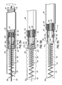
- FIGS. 5A-5C are side-elevational views, in partial cross-section, of an alternative embodiment of a coil deployment device and a method of using the same.
- FIGS. 6A-6B are top plane views illustrating the mitral valve from the left ventricle before and after tissue plication with the helical fastener.
- FIGS. 7A-7B are elevational views of an alternative embodiments of the helical fastener.
- Implanting a tissue plication device can begin with percutaneously accessing the tissue in a known manner.
- FIG. 1A illustrates accessing the mitral valve 50 of the heart 52 from the left ventricle 54 .
- the left ventricle 54 can be percutaneously accessed through the aortic arch 58 from a suitable arterial access site, such as the femoral or iliac arteries.
- a suitable arterial access site such as the femoral or iliac arteries.
- the physician creates an incision sufficiently near the suitable artery and directs a guide-wire 62 through the arterial access site, up the aorta 64 , around the aortic arch 58 , through the aortic valve 60 , and between the pair of chordae tendineae 66 in the left ventricle 54 .
- the percutaneous access can be made from a superior arterial access site such that the tissue plication device is directed into the aortic arch 58 from the brachiocephalic trunk 67 , the left common carotid 68 , or the left subclavian arteries 69 .
- the tissue plication device is directed into the heart 52 from a venous access site through the vena cava 55 or the coronary sinus 56 .
- the physician can then steer the guide-wire 62 toward the posterior annulus 70 of the mitral valve 50 .
- the guide-wire 62 enters the mitral valve tissue near the P 2 region located medially at the base of the posterior leaflet 74 along the posterior annulus 70 ; however, in some embodiments it may be preferred for the guide-wire 62 to be inserted into the posterior annulus 70 near the P 1 region though this is not specifically shown.
- a guide catheter 86 can then be directed over the guide-wire 62 .
- the guide catheter 86 can be any suitable catheter that can be directed through the vascular system to aid in the delivery of subsequent surgical devices to the surgical site.
- the tissue plication device (described below) with a delivery sheath 90 can then be directed over the guide-wire 62 and through the lumen of the guide catheter 86 to the surgical site.
- the guide-wire 62 can include at least one fluoroscopic marker that allows for in vivo localization. The physician can then steer the distal tip of the guide-wire 62 into the P 2 region and around the posterior annulus 70 , as shown in FIG. 1B .
- the guide-wire 62 further includes a radio-frequency (RF) energy delivery tip for assisting with penetration through the mitral tissue.
- RF radio-frequency
- a suitable RF energy device may be coupled to the guide-wire 62 .
- tissue plication device (described below) is illustrated for use with the mitral valve 50 from within the left ventricle 54 , it would be understood that similar procedures and techniques could be used for directing and inserting the tissue plication device from within the left atrium 82 or from the circumflex artery (not shown).
- the tissue plication device can be a helical fastener 94 having a distal portion 98 with a first pitch, P 1 , and a proximal portion 102 with a second pitch, P 2 , that is smaller than the first pitch.
- the proximal portion 102 will have a greater number of coils per unit of distance as compared with the distal portion 98 .
- the first pitch can be about 5.08 mm (0.200 inches) and the second pitch can range from about 1.27 mm (0.050 inches) to about 2.54 mm (0.100 inches); however, these dimensions should not be considered limiting.
- the helical fastener 94 can be constructed from metals or metallic alloys, such as stainless steel, titanium, platinum, and nickel titanium; or from non-metal polymer materials such as polyetherimide, polyimide, polyester, and polyolefins, or from any other suitable bio-compatible material(s).
- the metal or non-metal construction can be further coated with polytetrafluoroethylene polymer (PTFE) to reduce the frictional coefficient of the helical fastener 94 .
- PTFE polytetrafluoroethylene polymer
- the helical fastener 94 can be formed on a spring winder where the metal or non-metal material is wound around a mandrel having the desired diameter. The material is supplied from a moveable carriage to the mandrel at a first speed to create the first pitch; a second speed of the moveable carriage creates the second pitch.
- the helical fastener 94 can be manufactured by winding the desired material around a fixture having the desired geometry. Once winding of the material is complete, the helical fastener 94 is released from the fixture and heat treated into the desired configuration.
- the distal end of the helical fastener 94 can be shaped into a distal tip 106 for penetrating or cutting through tissue. Accordingly, the distal tip 106 can be a sharpened point, knife-like, or other known shapes. Shaping of the distal tip 106 of the helical fastener 94 can be accomplished after the winding by heat treatment, grinding, or other means.
- the distal tip 106 can include a radio-frequency ablation tip 110 , which is coupled to a remote radio-frequency energy source 114 .
- the radio-frequency energy source 114 provides a radio-frequency energy to the ablation tip 110 of the distal tip 106 that is sufficient to burn through, or cauterize, tissue while the distal tip 106 is advancing into the tissue.
- the cauterizing of tissue can aid in the movement of the helical fastener 94 through the tissue and, in some instances, reduce bleeding.
- the method of implanting the helical fastener 94 can continue with reference to FIGS. 3A-3E .
- the distal tip 106 is advanced so that it emerges slightly from the distal end of the delivery sheath 90 and contacts the tissue 118 , as shown in FIG. 3A .
- the helical fastener 94 is advanced into a tissue 118 , as shown in FIG. 3B .
- the helical fastener 94 threads itself along the curvature of the tissue 118 , which can be accomplished by positioning the guide-wire 62 along the tissue 118 as a guide.
- the helical fastener 94 is preformed with shape memory material to have the desired end-result shape for the tissue 118 . As the preformed helical fastener 94 is advanced into the tissue 118 , it would follow its predetermined shape without the aid of the guide-wire 62 .
- the helical fastener 94 can at least partially extend around the tissue 118 .
- alternative embodiments will also be described below where the introducing and advancing of the helical fastener 94 into the tissue 118 includes at least partially embedding the helical fastener 94 within the tissue.
- FIG. 3C illustrates the continued advancement of the distal portion 98 of the helical fastener 94 into the tissue 118 , which is followed with the proximal portion 102 causing the tissue 118 to plicate.
- the plication of the tissue 118 is due to the variable pitch along the length of the helical fastener 94 . That is, as the helical fastener 94 is advanced along the tissue 118 , the change in the pitch between the distal and proximal portions 98 , 102 induces a localized compression of the tissue 118 .
- the smaller pitch associated with the proximal portion 102 causes an increase stress in the tissue 118 , biasing the tissue 118 to be plicated. This plication reduces the overall length of the tissue 118 .
- a hub 122 of the coil delivery device 126 begins to emerge from the delivery sheath 90 , as shown in FIG. 3D .
- the proximal portion 102 of the helical fastener 94 is uncoupled from the hub 122 in a manner described in greater detail below.
- the guide catheter 86 , delivery sheath 90 , coil delivery device 126 , and guide-wire 62 are then retracted from the surgical site leaving the helical fastener 94 in position over the now plicated tissue 118 , as shown in FIG. 3E .
- the coil deployment device 126 can include a torque coil 130 comprised of three alternating layers of coil 134 , 138 , 142 .
- the three alternating layers of coil 134 , 138 , 142 increase the torque capacity of the deployment device over the distance between the arterial access site and the surgical site.
- Suitable torque coils 130 can include those commercially available, for example those by Asahi Intecc Co., Ltd.
- the three layers of coil 134 , 138 , 142 can be constructed, in one embodiment, from three layers of 0.1524 mm (0.006 inch) wire where the first layer is wound in a clockwise direction, the second layer is wound in the counter-clockwise direction, and the third layer is wound in a clockwise direction.
- the wire can be stainless steel or other known metal alloys capable of maintaining the necessary torque capacity while being surgically adaptable.
- the distal end of the torque coil 130 is equipped with the hub 122 , which can be welded, or otherwise fixed, to the distal end of the torque coil 130 .
- the hub 122 includes an adaptor cup 146 having a plurality of internal threads 150 approximately matching the pitch of the proximal portion 102 of the helical fastener 94 .
- the internal threads 150 allow the helical fastener 94 to be threadably engaged into the adaptor cup 146 .
- the adapter cup 146 defines a hollow interior space that receives the helical fastener 94 and is defined by a peripheral outer wall.
- the internal threads 150 are formed along the inner surface of the peripheral outer wall.
- the hub 122 includes a stop 123 that is in the form of a floor that is defined between the peripheral outer wall.
- the adaptor cup 146 of the coil deployment device 126 is pre-loaded with the proximal portion 102 of the helical fastener 94 .
- the coil deployment device 126 leading with the adaptor cup 146 and helical fastener 94 , are backloaded into the delivery sheath 90 , which are then backloaded, as a unit, into the guide catheter 86 ( FIG. 1 ), and along the guide-wire 62 .
- the coil deployment device 126 and delivery sheath 90 are advanced to the surgical site.
- the tissue 118 to be plicated is larger in diameter than the helical fastener 94 .
- the guide-wire 62 can be at least partially embedded within the tissue 118 .
- the physician can advance the distal tip 106 of the helical fastener 94 slightly beyond the delivery sheath 90 to engage the tissue 118 .
- the distal tip 106 and the distal portion 98 of the helical fastener 94 are advanced into the surrounding tissue 118 .
- the rotating advancement continues until the proximal portion 102 of the helical fastener 94 is within the tissue 118 , which begins to plicate.
- the physician begins disengaging the proximal portion 102 of the helical fastener 94 from the coil deployment device 126 .
- the physician reverses the direction of the rotation as shown by arrows 148 . Because the helical fastener 94 is more tightly engaged to the tissue 118 than the adaptor cup 146 , the reversed rotation causes the helical fastener 94 to decouple from the coil deployment device 126 .
- the coil deployment device 126 , guide catheter 86 , and guide-wire 62 are then retracted from the surgical site.
- a coil deployment device 152 can be constructed to allow for some retraction of the helical fastener 94 from the tissue 118 .
- the hub 122 of the coil deployment device 152 includes a collet 154 , as shown in FIGS. 5A-5C .
- the collet 154 includes at least two deflectable arms 158 connected to the hub 122 by elastic members 162 .
- the internal surface of the deflectable arms 158 receives the helical fastener 94 and can include dentate structures 160 to grasp the proximal portion 102 .
- the elastic members 162 can be springs, or similar structures, and are preferably arranged to bias the deflectable arms 158 open.
- the proximal portion 102 of the helical fastener 94 is inserted into the deflectable arms 158 which are then loaded into the delivery sheath 90 until the deflectable arms 158 are constrained within the delivery sheath 90 and grasp the proximal portion 102 .
- This constraint maintains the proximal portion 102 of the helical fastener 94 within the collet 154 .
- the coil deployment device 152 and delivery sheath 90 are then advanced to the surgical site.
- the proximal portion 102 of the helical fastener 94 is engaged within the collet 154 of the coil deployment device 152 and the physician can advance or retract the helical fastener 94 with respect to the tissue 118 by changing the direction of rotation.
- FIG. 5B illustrates the release of the helical fastener 94 from the coil deployment device 152 after the helical fastener 94 has been fully advanced into the tissue 118 .
- the physician advances the collet 154 beyond the distal end of the delivery sheath 90 such that the elastic members 162 bias the deflectable arms 158 outwardly.
- the physician can then retract the delivery sheath 90 , the coil deployment device 152 , and the guide catheter 86 from the surgical site, as shown in FIG. 5C .
- Release of the helical fastener 94 from the collet 154 can alternatively be accomplished by retracting the delivery sheath 90 from the collet 154 .
- FIGS. 6A and 6B illustrate the changes in the mitral valve 50 due to plication of the tissue 118 by the helical fastener 94 .
- FIG. 6A shows the mitral valve 50 before the helical fastener 94 is implanted where the posterior leaflet 74 is loose, does not coapt to the anterior leaflet 166 , and can potentially prolapse into the left atrium 82 .
- the posterior annulus 70 is plicated and reshaped such that the circumference of the posterior annulus 70 and the septal-lateral dimension are both decreased. This pulls the posterior leaflet 74 toward the anterior leaflet 166 and allows the leaflets 74 , 166 to fully coapt, thus increasing the efficiency of the mitral valve 50 .
- the tissue plication device can include a helical fastener 170 having a first configuration 170 a with a first pitch ( FIG. 7A ) that is capable of being converted to a second configuration 170 b with a second pitch ( FIG. 7B ) when a stimulus is applied.
- the first pitch can be greater than the second pitch.
- the helical fastener 170 shortens and plicates the tissue 118 .
- Suitable stimuli can include, but should not be limited to, thermal energy, magnetic energy, chemical reaction, mechanical energy, or combinations thereof, and can depend on factors such as the particular material(s) used in constructing the helical fastener 170 .
- Suitable materials can include, in addition to the materials described previously, any shape memory material. Suitable materials can thus include metal alloys such as nickel titanium alloys, cobalt nickel aluminum alloys, titanium palladium, copper aluminum nickel; or non-metal polymers, such as VERIFLEX by Cornerstone Research Group, Inc.
- the helical fastener material could be selected for its thermal response to temperatures that are approximately body temperature, i.e. greater than about 35.5° C. (96° F.).
- the helical fastener 170 is directed into the tissue 118 in a manner consistent with the methods described in detail above. After the helical fastener 170 is fully inserted within the tissue 118 , the physician can apply the necessary stimulus to cause the helical fastener 170 to convert from the first to the second configurations 170 a , 170 b . This conversion causes the length of the helical fastener 170 to decrease, which plicates the tissue 118 .
- the helical fastener is constructed such that the first configuration has a smaller pitch than the second configuration.
- the stimulus is applied to the helical fastener before introducing the helical fastener to the tissue.
- the helical fastener in the second configuration is directed and advanced into the tissue. Once the helical fastener is within, or surrounds, the tissue, the stimulus is removed and the helical fastener converts to the first configuration, thereby plicating the tissue.
- the helical fastener can be constructed to have particular thermodynamic properties that affect the rate at which the helical fastener absorbs thermal energy.
- a first helical fastener constructed from a nickel titanium alloy having an outer diameter of 1.016 mm (0.040 inches) will have a greater mass than a second helical fastener constructed with an outer diameter of 0.508 mm (0.020 inches). Accordingly, one skilled in the art would understand that the larger first helical fastener would require a greater amount of thermal energy than the smaller helical fastener to achieve a similar response.
- Other methods of altering the thermodynamic response of the helical fastener can include the application of an insulator coating, such as polytetrafluoroethylene, or ceramic materials, such as metal oxides (titanium oxide or calcium oxide), onto the helical fastener.
- an insulator coating such as polytetrafluoroethylene, or ceramic materials, such as metal oxides (titanium oxide or calcium oxide)
- Helical fasteners including these insulator coatings would absorb thermal energy at a slower rate than a similarly constructed helical fastener without the insulating coating material.
- Insulating coating materials can be added to the helical fastener construction by applying a shrink wrap tubing, dip coating processes, spray coating processes, thermal spray coating processes, or other known methods within the art.
- the mitral valve could be plicated from the left atrium.
- other openings through tissues could be plicated, including other heart valves.
Abstract
Description
Claims (11)
Priority Applications (1)
| Application Number | Priority Date | Filing Date | Title |
|---|---|---|---|
| US14/249,928 US9050187B2 (en) | 2008-02-26 | 2014-04-10 | Tissue plication devices and methods for their use |
Applications Claiming Priority (3)
| Application Number | Priority Date | Filing Date | Title |
|---|---|---|---|
| US3142608P | 2008-02-26 | 2008-02-26 | |
| US12/393,608 US8728097B1 (en) | 2008-02-26 | 2009-02-26 | Tissue plication devices and methods for their use |
| US14/249,928 US9050187B2 (en) | 2008-02-26 | 2014-04-10 | Tissue plication devices and methods for their use |
Related Parent Applications (1)
| Application Number | Title | Priority Date | Filing Date |
|---|---|---|---|
| US12/393,608 Continuation US8728097B1 (en) | 2008-02-26 | 2009-02-26 | Tissue plication devices and methods for their use |
Publications (2)
| Publication Number | Publication Date |
|---|---|
| US20140303720A1 US20140303720A1 (en) | 2014-10-09 |
| US9050187B2 true US9050187B2 (en) | 2015-06-09 |
Family
ID=50692188
Family Applications (2)
| Application Number | Title | Priority Date | Filing Date |
|---|---|---|---|
| US12/393,608 Active 2030-09-28 US8728097B1 (en) | 2008-02-26 | 2009-02-26 | Tissue plication devices and methods for their use |
| US14/249,928 Expired - Fee Related US9050187B2 (en) | 2008-02-26 | 2014-04-10 | Tissue plication devices and methods for their use |
Family Applications Before (1)
| Application Number | Title | Priority Date | Filing Date |
|---|---|---|---|
| US12/393,608 Active 2030-09-28 US8728097B1 (en) | 2008-02-26 | 2009-02-26 | Tissue plication devices and methods for their use |
Country Status (1)
| Country | Link |
|---|---|
| US (2) | US8728097B1 (en) |
Cited By (6)
| Publication number | Priority date | Publication date | Assignee | Title |
|---|---|---|---|---|
| US10543090B2 (en) | 2016-12-30 | 2020-01-28 | Pipeline Medical Technologies, Inc. | Neo chordae tendinae deployment system |
| US10667910B2 (en) | 2016-12-30 | 2020-06-02 | Pipeline Medical Technologies, Inc. | Method and apparatus for transvascular implantation of neo chordae tendinae |
| US10925731B2 (en) | 2016-12-30 | 2021-02-23 | Pipeline Medical Technologies, Inc. | Method and apparatus for transvascular implantation of neo chordae tendinae |
| US11026791B2 (en) | 2018-03-20 | 2021-06-08 | Medtronic Vascular, Inc. | Flexible canopy valve repair systems and methods of use |
| US11285003B2 (en) | 2018-03-20 | 2022-03-29 | Medtronic Vascular, Inc. | Prolapse prevention device and methods of use thereof |
| US11696828B2 (en) | 2016-12-30 | 2023-07-11 | Pipeline Medical Technologies, Inc. | Method and apparatus for mitral valve chord repair |
Families Citing this family (73)
| Publication number | Priority date | Publication date | Assignee | Title |
|---|---|---|---|---|
| US8608797B2 (en) | 2005-03-17 | 2013-12-17 | Valtech Cardio Ltd. | Mitral valve treatment techniques |
| US8951285B2 (en) | 2005-07-05 | 2015-02-10 | Mitralign, Inc. | Tissue anchor, anchoring system and methods of using the same |
| US11259924B2 (en) | 2006-12-05 | 2022-03-01 | Valtech Cardio Ltd. | Implantation of repair devices in the heart |
| US9974653B2 (en) | 2006-12-05 | 2018-05-22 | Valtech Cardio, Ltd. | Implantation of repair devices in the heart |
| US11660190B2 (en) | 2007-03-13 | 2023-05-30 | Edwards Lifesciences Corporation | Tissue anchors, systems and methods, and devices |
| US8382829B1 (en) | 2008-03-10 | 2013-02-26 | Mitralign, Inc. | Method to reduce mitral regurgitation by cinching the commissure of the mitral valve |
| EP2296744B1 (en) | 2008-06-16 | 2019-07-31 | Valtech Cardio, Ltd. | Annuloplasty devices |
| EP2379008B1 (en) | 2008-12-22 | 2021-02-17 | Valtech Cardio, Ltd. | Adjustable annuloplasty devices |
| US10517719B2 (en) | 2008-12-22 | 2019-12-31 | Valtech Cardio, Ltd. | Implantation of repair devices in the heart |
| US8715342B2 (en) | 2009-05-07 | 2014-05-06 | Valtech Cardio, Ltd. | Annuloplasty ring with intra-ring anchoring |
| US9011530B2 (en) | 2008-12-22 | 2015-04-21 | Valtech Cardio, Ltd. | Partially-adjustable annuloplasty structure |
| US8911494B2 (en) | 2009-05-04 | 2014-12-16 | Valtech Cardio, Ltd. | Deployment techniques for annuloplasty ring |
| US8147542B2 (en) | 2008-12-22 | 2012-04-03 | Valtech Cardio, Ltd. | Adjustable repair chords and spool mechanism therefor |
| US8241351B2 (en) | 2008-12-22 | 2012-08-14 | Valtech Cardio, Ltd. | Adjustable partial annuloplasty ring and mechanism therefor |
| US8353956B2 (en) | 2009-02-17 | 2013-01-15 | Valtech Cardio, Ltd. | Actively-engageable movement-restriction mechanism for use with an annuloplasty structure |
| US9968452B2 (en) | 2009-05-04 | 2018-05-15 | Valtech Cardio, Ltd. | Annuloplasty ring delivery cathethers |
| US9180007B2 (en) | 2009-10-29 | 2015-11-10 | Valtech Cardio, Ltd. | Apparatus and method for guide-wire based advancement of an adjustable implant |
| US10098737B2 (en) | 2009-10-29 | 2018-10-16 | Valtech Cardio, Ltd. | Tissue anchor for annuloplasty device |
| US9011520B2 (en) | 2009-10-29 | 2015-04-21 | Valtech Cardio, Ltd. | Tissue anchor for annuloplasty device |
| WO2011067770A1 (en) | 2009-12-02 | 2011-06-09 | Valtech Cardio, Ltd. | Delivery tool for implantation of spool assembly coupled to a helical anchor |
| US8870950B2 (en) | 2009-12-08 | 2014-10-28 | Mitral Tech Ltd. | Rotation-based anchoring of an implant |
| US10058323B2 (en) | 2010-01-22 | 2018-08-28 | 4 Tech Inc. | Tricuspid valve repair using tension |
| US8475525B2 (en) | 2010-01-22 | 2013-07-02 | 4Tech Inc. | Tricuspid valve repair using tension |
| US9307980B2 (en) | 2010-01-22 | 2016-04-12 | 4Tech Inc. | Tricuspid valve repair using tension |
| US11653910B2 (en) | 2010-07-21 | 2023-05-23 | Cardiovalve Ltd. | Helical anchor implantation |
| US10792152B2 (en) | 2011-06-23 | 2020-10-06 | Valtech Cardio, Ltd. | Closed band for percutaneous annuloplasty |
| US9918840B2 (en) | 2011-06-23 | 2018-03-20 | Valtech Cardio, Ltd. | Closed band for percutaneous annuloplasty |
| US8858623B2 (en) | 2011-11-04 | 2014-10-14 | Valtech Cardio, Ltd. | Implant having multiple rotational assemblies |
| EP3656434B1 (en) | 2011-11-08 | 2021-10-20 | Valtech Cardio, Ltd. | Controlled steering functionality for implant-delivery tool |
| WO2013163762A1 (en) | 2012-05-02 | 2013-11-07 | The Royal Institution For The Advancement Of Learning/Mcgill University | Device for soft tissue support and method for anchoring |
| WO2014052818A1 (en) | 2012-09-29 | 2014-04-03 | Mitralign, Inc. | Plication lock delivery system and method of use thereof |
| US10376266B2 (en) | 2012-10-23 | 2019-08-13 | Valtech Cardio, Ltd. | Percutaneous tissue anchor techniques |
| WO2014064694A2 (en) | 2012-10-23 | 2014-05-01 | Valtech Cardio, Ltd. | Controlled steering functionality for implant-delivery tool |
| US9730793B2 (en) | 2012-12-06 | 2017-08-15 | Valtech Cardio, Ltd. | Techniques for guide-wire based advancement of a tool |
| CN105007832B (en) | 2013-01-09 | 2018-01-23 | 4科技有限公司 | Organize ancora equipment |
| EP2948103B1 (en) | 2013-01-24 | 2022-12-07 | Cardiovalve Ltd | Ventricularly-anchored prosthetic valves |
| EP2961351B1 (en) | 2013-02-26 | 2018-11-28 | Mitralign, Inc. | Devices for percutaneous tricuspid valve repair |
| WO2014141239A1 (en) | 2013-03-14 | 2014-09-18 | 4Tech Inc. | Stent with tether interface |
| US10449333B2 (en) | 2013-03-14 | 2019-10-22 | Valtech Cardio, Ltd. | Guidewire feeder |
| US9724195B2 (en) | 2013-03-15 | 2017-08-08 | Mitralign, Inc. | Translation catheters and systems |
| US10070857B2 (en) | 2013-08-31 | 2018-09-11 | Mitralign, Inc. | Devices and methods for locating and implanting tissue anchors at mitral valve commissure |
| US10299793B2 (en) | 2013-10-23 | 2019-05-28 | Valtech Cardio, Ltd. | Anchor magazine |
| US10052095B2 (en) | 2013-10-30 | 2018-08-21 | 4Tech Inc. | Multiple anchoring-point tension system |
| US10022114B2 (en) | 2013-10-30 | 2018-07-17 | 4Tech Inc. | Percutaneous tether locking |
| US9610162B2 (en) | 2013-12-26 | 2017-04-04 | Valtech Cardio, Ltd. | Implantation of flexible implant |
| EP3157607B1 (en) | 2014-06-19 | 2019-08-07 | 4Tech Inc. | Cardiac tissue cinching |
| US20160007993A1 (en) * | 2014-07-09 | 2016-01-14 | Boston Scientific Scimed, Inc. | Revolving approximation device |
| US10806905B2 (en) * | 2014-08-05 | 2020-10-20 | Cardiovascular Systems, Inc. | Reformable guidewire tip |
| US10195030B2 (en) | 2014-10-14 | 2019-02-05 | Valtech Cardio, Ltd. | Leaflet-restraining techniques |
| CN106999178B (en) | 2014-12-02 | 2019-12-24 | 4科技有限公司 | Eccentric tissue anchor |
| EP3253333B1 (en) | 2015-02-05 | 2024-04-03 | Cardiovalve Ltd | Prosthetic valve with axially-sliding frames |
| US20160256269A1 (en) | 2015-03-05 | 2016-09-08 | Mitralign, Inc. | Devices for treating paravalvular leakage and methods use thereof |
| CN114515173A (en) | 2015-04-30 | 2022-05-20 | 瓦尔泰克卡迪欧有限公司 | Valvuloplasty techniques |
| JP6902533B2 (en) | 2015-10-02 | 2021-07-14 | コーニンクレッカ フィリップス エヌ ヴェKoninklijke Philips N.V. | Hub for device placement with shape detection system |
| US10751182B2 (en) | 2015-12-30 | 2020-08-25 | Edwards Lifesciences Corporation | System and method for reshaping right heart |
| WO2017117370A2 (en) | 2015-12-30 | 2017-07-06 | Mitralign, Inc. | System and method for reducing tricuspid regurgitation |
| US10531866B2 (en) | 2016-02-16 | 2020-01-14 | Cardiovalve Ltd. | Techniques for providing a replacement valve and transseptal communication |
| US10702274B2 (en) | 2016-05-26 | 2020-07-07 | Edwards Lifesciences Corporation | Method and system for closing left atrial appendage |
| GB201611910D0 (en) | 2016-07-08 | 2016-08-24 | Valtech Cardio Ltd | Adjustable annuloplasty device with alternating peaks and troughs |
| WO2018029680A1 (en) | 2016-08-10 | 2018-02-15 | Mitraltech Ltd. | Prosthetic valve with concentric frames |
| US11045627B2 (en) | 2017-04-18 | 2021-06-29 | Edwards Lifesciences Corporation | Catheter system with linear actuation control mechanism |
| US10835221B2 (en) | 2017-11-02 | 2020-11-17 | Valtech Cardio, Ltd. | Implant-cinching devices and systems |
| US11135062B2 (en) | 2017-11-20 | 2021-10-05 | Valtech Cardio Ltd. | Cinching of dilated heart muscle |
| CN111655200B (en) | 2018-01-24 | 2023-07-14 | 爱德华兹生命科学创新(以色列)有限公司 | Contraction of annuloplasty structures |
| WO2019145941A1 (en) | 2018-01-26 | 2019-08-01 | Valtech Cardio, Ltd. | Techniques for facilitating heart valve tethering and chord replacement |
| US11026673B2 (en) | 2018-05-10 | 2021-06-08 | Edwards Lifesciences Corporation | Corkscrew tissue anchor |
| CA3106104A1 (en) | 2018-07-12 | 2020-01-16 | Valtech Cardio, Ltd. | Annuloplasty systems and locking tools therefor |
| US11376126B2 (en) * | 2019-04-16 | 2022-07-05 | Neochord, Inc. | Transverse helical cardiac anchor for minimally invasive heart valve repair |
| CN114786621A (en) | 2019-10-29 | 2022-07-22 | 爱德华兹生命科学创新(以色列)有限公司 | Annuloplasty and tissue anchoring techniques |
| US20210369454A1 (en) * | 2020-02-10 | 2021-12-02 | Synedcor LLC | System and Method for Percutaneously Delivering a Tricuspid Valve |
| CN111166398B (en) * | 2020-02-21 | 2021-07-06 | 西安交通大学 | Positive and negative guide wire magnetic kissing system for coronary artery occlusion intervention |
| US11616524B2 (en) * | 2020-06-23 | 2023-03-28 | Joseph K. Greco | Shield for a first responder radio |
| WO2022046901A1 (en) * | 2020-08-27 | 2022-03-03 | The Brigham And Women's Hospital, Inc. | Helical bone fixation device |
Citations (8)
| Publication number | Priority date | Publication date | Assignee | Title |
|---|---|---|---|---|
| US5407427A (en) * | 1992-06-16 | 1995-04-18 | Loma Linda University Medical Center | Trocar facilitator for endoscopic surgery |
| US20030216693A1 (en) | 2000-08-08 | 2003-11-20 | Mickley Timothy J. | Tortuous path injection device and method |
| US6663633B1 (en) | 2000-10-25 | 2003-12-16 | Pierson, Iii Raymond H. | Helical orthopedic fixation and reduction device, insertion system, and associated methods |
| US6776791B1 (en) * | 1998-04-01 | 2004-08-17 | Endovascular Technologies, Inc. | Stent and method and device for packing of same |
| US20060015002A1 (en) | 2004-07-15 | 2006-01-19 | Micardia Corporation | Shape memory devices and methods for reshaping heart anatomy |
| US20060020326A9 (en) * | 2001-11-28 | 2006-01-26 | Aptus Endosystems, Inc. | Systems and methods for attaching a prosthesis within a body lumen or hollow organ |
| US20070225737A1 (en) * | 2006-03-21 | 2007-09-27 | Ethicon Endo-Surgery, Inc. | Surgical fastener and instrument |
| US20070244555A1 (en) | 2006-04-12 | 2007-10-18 | Medtronic Vascular, Inc. | Annuloplasty Device Having a Helical Anchor and Methods for its Use |
-
2009
- 2009-02-26 US US12/393,608 patent/US8728097B1/en active Active
-
2014
- 2014-04-10 US US14/249,928 patent/US9050187B2/en not_active Expired - Fee Related
Patent Citations (8)
| Publication number | Priority date | Publication date | Assignee | Title |
|---|---|---|---|---|
| US5407427A (en) * | 1992-06-16 | 1995-04-18 | Loma Linda University Medical Center | Trocar facilitator for endoscopic surgery |
| US6776791B1 (en) * | 1998-04-01 | 2004-08-17 | Endovascular Technologies, Inc. | Stent and method and device for packing of same |
| US20030216693A1 (en) | 2000-08-08 | 2003-11-20 | Mickley Timothy J. | Tortuous path injection device and method |
| US6663633B1 (en) | 2000-10-25 | 2003-12-16 | Pierson, Iii Raymond H. | Helical orthopedic fixation and reduction device, insertion system, and associated methods |
| US20060020326A9 (en) * | 2001-11-28 | 2006-01-26 | Aptus Endosystems, Inc. | Systems and methods for attaching a prosthesis within a body lumen or hollow organ |
| US20060015002A1 (en) | 2004-07-15 | 2006-01-19 | Micardia Corporation | Shape memory devices and methods for reshaping heart anatomy |
| US20070225737A1 (en) * | 2006-03-21 | 2007-09-27 | Ethicon Endo-Surgery, Inc. | Surgical fastener and instrument |
| US20070244555A1 (en) | 2006-04-12 | 2007-10-18 | Medtronic Vascular, Inc. | Annuloplasty Device Having a Helical Anchor and Methods for its Use |
Cited By (18)
| Publication number | Priority date | Publication date | Assignee | Title |
|---|---|---|---|---|
| US11684475B2 (en) | 2016-12-30 | 2023-06-27 | Pipeline Medical Technologies, Inc. | Method and apparatus for transvascular implantation of neo chordae tendinae |
| US10617523B2 (en) | 2016-12-30 | 2020-04-14 | Pipeline Medical Technologies, Inc. | Tissue anchor with dynamic depth indicator |
| US11083580B2 (en) | 2016-12-30 | 2021-08-10 | Pipeline Medical Technologies, Inc. | Method of securing a leaflet anchor to a mitral valve leaflet |
| US11931262B2 (en) | 2016-12-30 | 2024-03-19 | Pipeline Medical Technologies, Inc. | Method and apparatus for transvascular implantation of neo chordae tendinae |
| US10667910B2 (en) | 2016-12-30 | 2020-06-02 | Pipeline Medical Technologies, Inc. | Method and apparatus for transvascular implantation of neo chordae tendinae |
| US10675150B2 (en) | 2016-12-30 | 2020-06-09 | Pipeline Medical Technologies, Inc. | Method for transvascular implantation of neo chordae tendinae |
| US10682230B2 (en) | 2016-12-30 | 2020-06-16 | Pipeline Medical Technologies, Inc. | Apparatus for transvascular implantation of neo chordae tendinae |
| US10925731B2 (en) | 2016-12-30 | 2021-02-23 | Pipeline Medical Technologies, Inc. | Method and apparatus for transvascular implantation of neo chordae tendinae |
| US11696828B2 (en) | 2016-12-30 | 2023-07-11 | Pipeline Medical Technologies, Inc. | Method and apparatus for mitral valve chord repair |
| US10548733B2 (en) | 2016-12-30 | 2020-02-04 | Pipeline Medical Technologies, Inc. | Method of transvascular prosthetic chordae tendinae implantation |
| US10660753B2 (en) | 2016-12-30 | 2020-05-26 | Pipeline Medical Techologies, Inc. | Leaflet capture and anchor deployment system |
| US11666441B2 (en) | 2016-12-30 | 2023-06-06 | Pipeline Medical Technologies, Inc. | Endovascular suture lock |
| US10543090B2 (en) | 2016-12-30 | 2020-01-28 | Pipeline Medical Technologies, Inc. | Neo chordae tendinae deployment system |
| US11690719B2 (en) | 2016-12-30 | 2023-07-04 | Pipeline Medical Technologies, Inc. | Leaflet capture and anchor deployment system |
| US11931261B2 (en) | 2018-03-20 | 2024-03-19 | Medtronic Vascular, Inc. | Prolapse prevention device and methods of use thereof |
| US11701228B2 (en) | 2018-03-20 | 2023-07-18 | Medtronic Vascular, Inc. | Flexible canopy valve repair systems and methods of use |
| US11285003B2 (en) | 2018-03-20 | 2022-03-29 | Medtronic Vascular, Inc. | Prolapse prevention device and methods of use thereof |
| US11026791B2 (en) | 2018-03-20 | 2021-06-08 | Medtronic Vascular, Inc. | Flexible canopy valve repair systems and methods of use |
Also Published As
| Publication number | Publication date |
|---|---|
| US8728097B1 (en) | 2014-05-20 |
| US20140303720A1 (en) | 2014-10-09 |
Similar Documents
| Publication | Publication Date | Title |
|---|---|---|
| US9050187B2 (en) | Tissue plication devices and methods for their use | |
| US11865001B2 (en) | Cardiac valve downsizing device and method | |
| US20220023046A1 (en) | Tissue grasping devices and related methods | |
| US10849749B2 (en) | Helical coil mitral valve annuloplasty systems and methods | |
| CN109715078B (en) | Tissue grasping device and related methods | |
| US10478302B2 (en) | Material for treatment of a heart valve, in particular a mitral valve | |
| US20070100439A1 (en) | Chordae tendinae restraining ring | |
| JP4551600B2 (en) | Percutaneous mitral annuloplasty and cardiac reinforcement | |
| US20200121460A1 (en) | Tissue cutting systems, devices and methods | |
| US20040210240A1 (en) | Method and repair device for treating mitral valve insufficiency | |
| US20070255396A1 (en) | Chrodae Tendinae Girdle | |
| US20120296349A1 (en) | Percutaneous Mitral Annulus Mini-Plication | |
| US20070250160A1 (en) | Device, system, and method for treating cardiac valve regurgitation | |
| US20070093869A1 (en) | Device, system, and method for contracting tissue in a mammalian body | |
| US20220168014A1 (en) | Systems, apparatuses, and methods for removing a medical implant from cardiac tissue | |
| US20220054186A1 (en) | Tissue excision, cutting, and removal systems and methods | |
| US11950827B2 (en) | Tissue excision, cutting, and removal systems and methods | |
| US20220168036A1 (en) | Systems, apparatuses, and methods for removing a medical implant from cardiac tissue | |
| US20240115385A1 (en) | Cardiac Valve Downsizing Device and Method | |
| US20210161664A1 (en) | Coil and barb anchors for heart valve repair devices | |
| JP2023533482A (en) | Devices, systems, and methods for cardiac annulus augmentation |
Legal Events
| Date | Code | Title | Description |
|---|---|---|---|
| AS | Assignment |
Owner name: MITRALIGN, INC., MASSACHUSETTS Free format text: ASSIGNMENT OF ASSIGNORS INTEREST;ASSIGNORS:SUGIMOTO, HIROATSU;LANE, JOSEPH P.;REEL/FRAME:034582/0382 Effective date: 20090416 |
|
| AS | Assignment |
Owner name: GENERAL ELECTRIC CAPITAL CORPORATION, MARYLAND Free format text: SECURITY INTEREST;ASSIGNOR:MITRALIGN, INC.;REEL/FRAME:034635/0173 Effective date: 20141231 |
|
| AS | Assignment |
Owner name: MITRALIGN, INC., MASSACHUSETTS Free format text: ASSIGNMENT OF ASSIGNORS INTEREST;ASSIGNORS:SUGIMOTO, HIROATSU;LANE, JOSEPH P.;SIGNING DATES FROM 20150102 TO 20150105;REEL/FRAME:034641/0847 |
|
| STCF | Information on status: patent grant |
Free format text: PATENTED CASE |
|
| AS | Assignment |
Owner name: HEALTHCARE FINANCIAL SOLUTIONS, LLC, SUCCESSOR AGE Free format text: ASSIGNMENT OF INTELLECTUAL PROPERTY SECURITY INTEREST;ASSIGNOR:GENERAL ELECTRIC CAPITAL CORPORATION, RETIRING AGENT;REEL/FRAME:037146/0250 Effective date: 20151117 |
|
| AS | Assignment |
Owner name: SOLAR CAPITAL LTD., AS SUCCESSOR AGENT, NEW YORK Free format text: ASSIGNMENT OF INTELLECTUAL PROPERTY SECURITY AGREEMENT;ASSIGNOR:HEALTHCARE FINANCIAL SOLUTIONS, LLC, AS RETIRING AGENT;REEL/FRAME:038806/0390 Effective date: 20160513 |
|
| FEPP | Fee payment procedure |
Free format text: MAINTENANCE FEE REMINDER MAILED (ORIGINAL EVENT CODE: REM.); ENTITY STATUS OF PATENT OWNER: SMALL ENTITY |
|
| FEPP | Fee payment procedure |
Free format text: ENTITY STATUS SET TO UNDISCOUNTED (ORIGINAL EVENT CODE: BIG.); ENTITY STATUS OF PATENT OWNER: LARGE ENTITY |
|
| FEPP | Fee payment procedure |
Free format text: SURCHARGE FOR LATE PAYMENT, LARGE ENTITY (ORIGINAL EVENT CODE: M1554); ENTITY STATUS OF PATENT OWNER: LARGE ENTITY |
|
| MAFP | Maintenance fee payment |
Free format text: PAYMENT OF MAINTENANCE FEE, 4TH YEAR, LARGE ENTITY (ORIGINAL EVENT CODE: M1551); ENTITY STATUS OF PATENT OWNER: LARGE ENTITY Year of fee payment: 4 |
|
| AS | Assignment |
Owner name: EDWARDS LIFESCIENCES CORPORATION, CALIFORNIA Free format text: ASSIGNMENT OF ASSIGNORS INTEREST;ASSIGNOR:MITRALIGN, INC.;REEL/FRAME:048941/0323 Effective date: 20190307 |
|
| AS | Assignment |
Owner name: MITRALIGN, INC., MASSACHUSETTS Free format text: RELEASE BY SECURED PARTY;ASSIGNOR:SOLAR CAPITAL LTD;REEL/FRAME:049329/0183 Effective date: 20190528 |
|
| FEPP | Fee payment procedure |
Free format text: MAINTENANCE FEE REMINDER MAILED (ORIGINAL EVENT CODE: REM.); ENTITY STATUS OF PATENT OWNER: LARGE ENTITY |
|
| LAPS | Lapse for failure to pay maintenance fees |
Free format text: PATENT EXPIRED FOR FAILURE TO PAY MAINTENANCE FEES (ORIGINAL EVENT CODE: EXP.); ENTITY STATUS OF PATENT OWNER: LARGE ENTITY |
|
| STCH | Information on status: patent discontinuation |
Free format text: PATENT EXPIRED DUE TO NONPAYMENT OF MAINTENANCE FEES UNDER 37 CFR 1.362 |
|
| FP | Lapsed due to failure to pay maintenance fee |
Effective date: 20230609 |