US9005303B2 - Knee and shoulder joint prosthesis - Google Patents
Knee and shoulder joint prosthesis Download PDFInfo
- Publication number
- US9005303B2 US9005303B2 US12/596,658 US59665808A US9005303B2 US 9005303 B2 US9005303 B2 US 9005303B2 US 59665808 A US59665808 A US 59665808A US 9005303 B2 US9005303 B2 US 9005303B2
- Authority
- US
- United States
- Prior art keywords
- polymer material
- tray
- bone
- fixator
- tibial tray
- Prior art date
- Legal status (The legal status is an assumption and is not a legal conclusion. Google has not performed a legal analysis and makes no representation as to the accuracy of the status listed.)
- Expired - Fee Related, expires
Links
- 0 C(*CC12)C1C1*2C=CC1 Chemical compound C(*CC12)C1C1*2C=CC1 0.000 description 1
Images


Classifications
-
- A—HUMAN NECESSITIES
- A61—MEDICAL OR VETERINARY SCIENCE; HYGIENE
- A61F—FILTERS IMPLANTABLE INTO BLOOD VESSELS; PROSTHESES; DEVICES PROVIDING PATENCY TO, OR PREVENTING COLLAPSING OF, TUBULAR STRUCTURES OF THE BODY, e.g. STENTS; ORTHOPAEDIC, NURSING OR CONTRACEPTIVE DEVICES; FOMENTATION; TREATMENT OR PROTECTION OF EYES OR EARS; BANDAGES, DRESSINGS OR ABSORBENT PADS; FIRST-AID KITS
- A61F2/00—Filters implantable into blood vessels; Prostheses, i.e. artificial substitutes or replacements for parts of the body; Appliances for connecting them with the body; Devices providing patency to, or preventing collapsing of, tubular structures of the body, e.g. stents
- A61F2/02—Prostheses implantable into the body
- A61F2/30—Joints
- A61F2/40—Joints for shoulders
-
- A—HUMAN NECESSITIES
- A61—MEDICAL OR VETERINARY SCIENCE; HYGIENE
- A61F—FILTERS IMPLANTABLE INTO BLOOD VESSELS; PROSTHESES; DEVICES PROVIDING PATENCY TO, OR PREVENTING COLLAPSING OF, TUBULAR STRUCTURES OF THE BODY, e.g. STENTS; ORTHOPAEDIC, NURSING OR CONTRACEPTIVE DEVICES; FOMENTATION; TREATMENT OR PROTECTION OF EYES OR EARS; BANDAGES, DRESSINGS OR ABSORBENT PADS; FIRST-AID KITS
- A61F2/00—Filters implantable into blood vessels; Prostheses, i.e. artificial substitutes or replacements for parts of the body; Appliances for connecting them with the body; Devices providing patency to, or preventing collapsing of, tubular structures of the body, e.g. stents
- A61F2/02—Prostheses implantable into the body
- A61F2/30—Joints
- A61F2/38—Joints for elbows or knees
-
- A—HUMAN NECESSITIES
- A61—MEDICAL OR VETERINARY SCIENCE; HYGIENE
- A61B—DIAGNOSIS; SURGERY; IDENTIFICATION
- A61B17/00—Surgical instruments, devices or methods, e.g. tourniquets
- A61B17/00234—Surgical instruments, devices or methods, e.g. tourniquets for minimally invasive surgery
- A61B2017/00287—Bags for minimally invasive surgery
-
- A—HUMAN NECESSITIES
- A61—MEDICAL OR VETERINARY SCIENCE; HYGIENE
- A61B—DIAGNOSIS; SURGERY; IDENTIFICATION
- A61B17/00—Surgical instruments, devices or methods, e.g. tourniquets
- A61B2017/00831—Material properties
- A61B2017/00867—Material properties shape memory effect
- A61B2017/00871—Material properties shape memory effect polymeric
-
- A—HUMAN NECESSITIES
- A61—MEDICAL OR VETERINARY SCIENCE; HYGIENE
- A61F—FILTERS IMPLANTABLE INTO BLOOD VESSELS; PROSTHESES; DEVICES PROVIDING PATENCY TO, OR PREVENTING COLLAPSING OF, TUBULAR STRUCTURES OF THE BODY, e.g. STENTS; ORTHOPAEDIC, NURSING OR CONTRACEPTIVE DEVICES; FOMENTATION; TREATMENT OR PROTECTION OF EYES OR EARS; BANDAGES, DRESSINGS OR ABSORBENT PADS; FIRST-AID KITS
- A61F2/00—Filters implantable into blood vessels; Prostheses, i.e. artificial substitutes or replacements for parts of the body; Appliances for connecting them with the body; Devices providing patency to, or preventing collapsing of, tubular structures of the body, e.g. stents
- A61F2/02—Prostheses implantable into the body
- A61F2/30—Joints
- A61F2/30721—Accessories
- A61F2/30734—Modular inserts, sleeves or augments, e.g. placed on proximal part of stem for fixation purposes or wedges for bridging a bone defect
-
- A—HUMAN NECESSITIES
- A61—MEDICAL OR VETERINARY SCIENCE; HYGIENE
- A61F—FILTERS IMPLANTABLE INTO BLOOD VESSELS; PROSTHESES; DEVICES PROVIDING PATENCY TO, OR PREVENTING COLLAPSING OF, TUBULAR STRUCTURES OF THE BODY, e.g. STENTS; ORTHOPAEDIC, NURSING OR CONTRACEPTIVE DEVICES; FOMENTATION; TREATMENT OR PROTECTION OF EYES OR EARS; BANDAGES, DRESSINGS OR ABSORBENT PADS; FIRST-AID KITS
- A61F2/00—Filters implantable into blood vessels; Prostheses, i.e. artificial substitutes or replacements for parts of the body; Appliances for connecting them with the body; Devices providing patency to, or preventing collapsing of, tubular structures of the body, e.g. stents
- A61F2/02—Prostheses implantable into the body
- A61F2/30—Joints
- A61F2002/30001—Additional features of subject-matter classified in A61F2/28, A61F2/30 and subgroups thereof
- A61F2002/30003—Material related properties of the prosthesis or of a coating on the prosthesis
- A61F2002/3006—Properties of materials and coating materials
- A61F2002/30092—Properties of materials and coating materials using shape memory or superelastic materials, e.g. nitinol
-
- A—HUMAN NECESSITIES
- A61—MEDICAL OR VETERINARY SCIENCE; HYGIENE
- A61F—FILTERS IMPLANTABLE INTO BLOOD VESSELS; PROSTHESES; DEVICES PROVIDING PATENCY TO, OR PREVENTING COLLAPSING OF, TUBULAR STRUCTURES OF THE BODY, e.g. STENTS; ORTHOPAEDIC, NURSING OR CONTRACEPTIVE DEVICES; FOMENTATION; TREATMENT OR PROTECTION OF EYES OR EARS; BANDAGES, DRESSINGS OR ABSORBENT PADS; FIRST-AID KITS
- A61F2/00—Filters implantable into blood vessels; Prostheses, i.e. artificial substitutes or replacements for parts of the body; Appliances for connecting them with the body; Devices providing patency to, or preventing collapsing of, tubular structures of the body, e.g. stents
- A61F2/02—Prostheses implantable into the body
- A61F2/30—Joints
- A61F2002/30001—Additional features of subject-matter classified in A61F2/28, A61F2/30 and subgroups thereof
- A61F2002/30316—The prosthesis having different structural features at different locations within the same prosthesis; Connections between prosthetic parts; Special structural features of bone or joint prostheses not otherwise provided for
- A61F2002/30535—Special structural features of bone or joint prostheses not otherwise provided for
- A61F2002/30579—Special structural features of bone or joint prostheses not otherwise provided for with mechanically expandable devices, e.g. fixation devices
-
- A—HUMAN NECESSITIES
- A61—MEDICAL OR VETERINARY SCIENCE; HYGIENE
- A61F—FILTERS IMPLANTABLE INTO BLOOD VESSELS; PROSTHESES; DEVICES PROVIDING PATENCY TO, OR PREVENTING COLLAPSING OF, TUBULAR STRUCTURES OF THE BODY, e.g. STENTS; ORTHOPAEDIC, NURSING OR CONTRACEPTIVE DEVICES; FOMENTATION; TREATMENT OR PROTECTION OF EYES OR EARS; BANDAGES, DRESSINGS OR ABSORBENT PADS; FIRST-AID KITS
- A61F2210/00—Particular material properties of prostheses classified in groups A61F2/00 - A61F2/26 or A61F2/82 or A61F9/00 or A61F11/00 or subgroups thereof
- A61F2210/0014—Particular material properties of prostheses classified in groups A61F2/00 - A61F2/26 or A61F2/82 or A61F9/00 or A61F11/00 or subgroups thereof using shape memory or superelastic materials, e.g. nitinol
Definitions
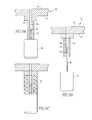
- FIG. 17 shows a perspective view of a thirteenth embodiment of a tibial tray of the present disclosure.
- the polymeric materials can be formed as a composite or matrix and include reinforcing material or phases such as fibers, rods, platelets, and fillers.
- the polymeric material can include glass fibers, carbon fibers, polymeric fibers, ceramic fibers, or ceramic particulates. Other reinforcing material or phases known to one of ordinary skill in the art could also be used.
- a tibial tray having metal posts and a shape memory polymer fixator and a tibial tray having shape memory polymer posts and a shape memory polymer fixator were both implanted into 20 pcf synthetic test bone (sawbone). Fixation of the trays into the sawbone was achieved by heating the shape memory polymer material using hot water at 70° C. for 10 minutes. The samples were left to cool to room temperature prior to mechanical testing. Mechanical testing was performed on an Instron. Each tray was clamped in place and a tensile mechanical test was performed to pull the trays out of the sawbone block. The Instron was set up at a displacement of 1 mm per minute and the forces throughout the experiment were recorded. The test ended when fixation failed.
- the tibial tray having metal posts and a shape memory polymer fixator had a pull-out value of 525 N and the tibial tray having shape memory polymer posts and a shape memory polymer fixator had a pull-out value of 960 N.
Abstract
Description
Claims (23)
Priority Applications (1)
| Application Number | Priority Date | Filing Date | Title |
|---|---|---|---|
| US12/596,658 US9005303B2 (en) | 2007-04-19 | 2008-04-16 | Knee and shoulder joint prosthesis |
Applications Claiming Priority (5)
| Application Number | Priority Date | Filing Date | Title |
|---|---|---|---|
| US91274007P | 2007-04-19 | 2007-04-19 | |
| US91269307P | 2007-04-19 | 2007-04-19 | |
| US98864007P | 2007-11-16 | 2007-11-16 | |
| PCT/US2008/060406 WO2008130956A2 (en) | 2007-04-19 | 2008-04-16 | Knee and shoulder joint prosthesis |
| US12/596,658 US9005303B2 (en) | 2007-04-19 | 2008-04-16 | Knee and shoulder joint prosthesis |
Publications (2)
| Publication Number | Publication Date |
|---|---|
| US20100222889A1 US20100222889A1 (en) | 2010-09-02 |
| US9005303B2 true US9005303B2 (en) | 2015-04-14 |
Family
ID=39635632
Family Applications (1)
| Application Number | Title | Priority Date | Filing Date |
|---|---|---|---|
| US12/596,658 Expired - Fee Related US9005303B2 (en) | 2007-04-19 | 2008-04-16 | Knee and shoulder joint prosthesis |
Country Status (7)
| Country | Link |
|---|---|
| US (1) | US9005303B2 (en) |
| EP (1) | EP2148638A2 (en) |
| JP (1) | JP5443335B2 (en) |
| CN (1) | CN102137637B (en) |
| AU (1) | AU2008243037A1 (en) |
| CA (1) | CA2686119A1 (en) |
| WO (1) | WO2008130956A2 (en) |
Families Citing this family (10)
| Publication number | Priority date | Publication date | Assignee | Title |
|---|---|---|---|---|
| US8177849B2 (en) | 2007-05-07 | 2012-05-15 | Zimmer, Inc. | Methods and apparatuses for attaching tissue to orthopaedic implants |
| US8403995B2 (en) * | 2008-12-18 | 2013-03-26 | Depuy Products, Inc. | Device and method for determining proper seating of an orthopaedic prosthesis |
| US10251754B2 (en) * | 2011-01-05 | 2019-04-09 | Peter Forsell | Knee joint device |
| US9028501B2 (en) * | 2012-05-30 | 2015-05-12 | Depuy (Ireland) | Tibial orthopaedic surgical instruments and method of using same |
| WO2014123263A1 (en) | 2013-02-07 | 2014-08-14 | 서울대학교산학협력단 | Modularized patient-specific registration guide and system using same |
| US9289306B2 (en) * | 2013-03-15 | 2016-03-22 | Catalyst Orthopaedics Llc | Humeral arthroplasty |
| US9408699B2 (en) * | 2013-03-15 | 2016-08-09 | Smed-Ta/Td, Llc | Removable augment for medical implant |
| CN105943138B (en) * | 2016-05-18 | 2018-11-23 | 南京大学医学院附属鼓楼医院 | Medical fracture of surgical neck of humerus humerus head reduction fixture device |
| CN106137466B (en) * | 2016-06-24 | 2017-09-15 | 陶冶 | A kind of selectable Bones and joints building mortion of clinical patient |
| US11571310B2 (en) | 2019-04-03 | 2023-02-07 | Catalyst Orthoscience Inc. | Stemmed implant |
Citations (36)
| Publication number | Priority date | Publication date | Assignee | Title |
|---|---|---|---|---|
| DE1604403B1 (en) | 1965-04-26 | 1970-11-26 | Francine Adany | Method and device for producing a heat-shrink tube from thermoplastic material |
| US3856905A (en) | 1972-09-22 | 1974-12-24 | Dow Chemical Co | Oriented plastic tube |
| GB1416575A (en) | 1973-04-18 | 1975-12-03 | Sakai Kasei Kogyo Kk | Apparatus for continuous production of biaxially shrinkable thermoplastic synthetic resin tube |
| US3926459A (en) | 1972-12-22 | 1975-12-16 | Jacques Pontigny | Dilatable tube, method for its production and applications thereof |
| JPS5164794A (en) | 1974-10-14 | 1976-06-04 | Atomic Energy Authority Uk | KAIRYOSHITAHOTEI |
| FR2378505A1 (en) | 1976-07-28 | 1978-08-25 | Rambert Andre | Partial surgical prosthesis for knee - has femoral plate and bearing pad inserted into separate sockets fixed into ends of bones |
| GB2004465A (en) | 1977-09-16 | 1979-04-04 | Bousquet G | Partial knee prosthesis |
| DE3036611A1 (en) | 1980-09-29 | 1982-06-09 | Kabel- und Metallwerke Gutehoffnungshütte AG, 3000 Hannover | Sealed connection esp. between cable and duct - produced using hot-shrink thermoplastics tube which shrinks at one end and expands at the other |
| US4950258A (en) | 1988-01-28 | 1990-08-21 | Japan Medical Supply Co., Ltd. | Plastic molded articles with shape memory property |
| US5108289A (en) | 1991-04-10 | 1992-04-28 | Sekio Fukuyo | Dental endosseous implant |
| WO1996022061A1 (en) | 1995-01-20 | 1996-07-25 | Jeffcoat Robert L | Elastically stabilized endosseous dental implant |
| JPH09149909A (en) | 1995-11-30 | 1997-06-10 | Kyocera Corp | Artificial knee joint |
| JPH09234241A (en) | 1996-02-29 | 1997-09-09 | Shimadzu Corp | Orthosis having thermally deforming property |
| US5951288A (en) | 1998-07-03 | 1999-09-14 | Sawa; Shlaimon T. | Self expanding dental implant and method for using the same |
| DE19829589A1 (en) | 1998-07-02 | 2000-01-20 | Univ Eberhard Karls | Device for anchoring an endoprosthesis in a bone |
| FR2784288A1 (en) | 1998-10-07 | 2000-04-14 | Franck Bresler | IMPLANT TO BE FIXED TO A BONE |
| JP2000126213A (en) | 1998-09-18 | 2000-05-09 | Johnson & Johnson Professional Inc | Module type knee prosthesis provided thigh bone stem having boss structure part |
| EP1000958A1 (en) | 1998-11-12 | 2000-05-17 | Takiron Co. Ltd. | Shape-memory, biodegradable and absorbable material |
| US6160084A (en) | 1998-02-23 | 2000-12-12 | Massachusetts Institute Of Technology | Biodegradable shape memory polymers |
| JP2001087292A (en) | 1999-09-27 | 2001-04-03 | Kobe Steel Ltd | Tibia tray |
| US6277390B1 (en) | 1998-10-21 | 2001-08-21 | Sulzer Orthopaedie Ag | UHMW polyethylene for implants |
| US6299448B1 (en) | 1999-02-17 | 2001-10-09 | Ivanka J. Zdrahala | Surgical implant system for restoration and repair of body function |
| JP2001293019A (en) | 2000-03-17 | 2001-10-23 | Depuy Orthopaedics Inc | Apparatus for fixing joint cavity part without cement on surface of joint cavity of scapular joint cavity |
| US20040030341A1 (en) | 2001-03-02 | 2004-02-12 | Marcel Aeschlimann | Implants, device and method for joining tissue parts |
| US6875235B2 (en) * | 1999-10-08 | 2005-04-05 | Bret A. Ferree | Prosthetic joints with contained compressible resilient members |
| FR2863478A1 (en) | 2003-12-10 | 2005-06-17 | Pierre Luc Reynaud | Dental restoration prosthesis comprises a rigid core surrounded by a sheath made of a material that loses its mechanical bonding characteristics when subjected to a stimulus |
| US20050143837A1 (en) | 2002-06-27 | 2005-06-30 | Ferree Bret A. | Arthroplasty devices configured to reduce shear stress |
| US20060190086A1 (en) | 2005-02-22 | 2006-08-24 | Mako Surgical Corporation | Knee implant |
| US20060241759A1 (en) * | 2005-04-25 | 2006-10-26 | Sdgi Holdings, Inc. | Oriented polymeric spinal implants |
| DE102005032005A1 (en) | 2005-07-08 | 2007-01-11 | Adolf Pfaff Dr. Karl-Friedrich Reichenbach Gbr (Vertretungsberechtigter Gesellschafter: Adolf Pfaff, 79183 Waldkirch) | Filling material pin for filling a tooth root canal is made from a flexible memory material which expands on heating to a specified temperature |
| WO2007024689A2 (en) | 2005-08-22 | 2007-03-01 | The General Hospital Corporation Dba Massachusetts General Hospital | Oxidation resistant homogenized polymeric material |
| EP1762201A1 (en) | 2005-09-08 | 2007-03-14 | Biomet Manufacturing Corporation | Method and apparatus for a glenoid prosthesis |
| US20070083205A1 (en) | 2005-09-26 | 2007-04-12 | Mohamed Attawia | Tissue augmentation, stabilization and regeneration Technique |
| WO2007101267A1 (en) | 2006-03-01 | 2007-09-07 | Warsaw Orthopedic, Inc. | Bone anchors and methods of forming the same |
| WO2008131197A1 (en) | 2007-04-19 | 2008-10-30 | Smith & Nephew, Inc. | Multi-modal shape memory polymers |
| US20090149856A1 (en) | 2007-12-05 | 2009-06-11 | Bioretec Oy | Medical device and its manufacture |
-
2008
- 2008-04-16 US US12/596,658 patent/US9005303B2/en not_active Expired - Fee Related
- 2008-04-16 CN CN200880021062.3A patent/CN102137637B/en not_active Expired - Fee Related
- 2008-04-16 CA CA002686119A patent/CA2686119A1/en not_active Abandoned
- 2008-04-16 EP EP08745914A patent/EP2148638A2/en not_active Withdrawn
- 2008-04-16 AU AU2008243037A patent/AU2008243037A1/en not_active Abandoned
- 2008-04-16 WO PCT/US2008/060406 patent/WO2008130956A2/en active Application Filing
- 2008-04-16 JP JP2010504202A patent/JP5443335B2/en not_active Expired - Fee Related
Patent Citations (43)
| Publication number | Priority date | Publication date | Assignee | Title |
|---|---|---|---|---|
| DE1604403B1 (en) | 1965-04-26 | 1970-11-26 | Francine Adany | Method and device for producing a heat-shrink tube from thermoplastic material |
| US3856905A (en) | 1972-09-22 | 1974-12-24 | Dow Chemical Co | Oriented plastic tube |
| US3926459A (en) | 1972-12-22 | 1975-12-16 | Jacques Pontigny | Dilatable tube, method for its production and applications thereof |
| GB1416575A (en) | 1973-04-18 | 1975-12-03 | Sakai Kasei Kogyo Kk | Apparatus for continuous production of biaxially shrinkable thermoplastic synthetic resin tube |
| JPS5164794A (en) | 1974-10-14 | 1976-06-04 | Atomic Energy Authority Uk | KAIRYOSHITAHOTEI |
| GB1507309A (en) | 1974-10-14 | 1978-04-12 | Atomic Energy Authority Uk | Prosthetic knee joints |
| FR2378505A1 (en) | 1976-07-28 | 1978-08-25 | Rambert Andre | Partial surgical prosthesis for knee - has femoral plate and bearing pad inserted into separate sockets fixed into ends of bones |
| GB2004465A (en) | 1977-09-16 | 1979-04-04 | Bousquet G | Partial knee prosthesis |
| DE3036611A1 (en) | 1980-09-29 | 1982-06-09 | Kabel- und Metallwerke Gutehoffnungshütte AG, 3000 Hannover | Sealed connection esp. between cable and duct - produced using hot-shrink thermoplastics tube which shrinks at one end and expands at the other |
| US4950258A (en) | 1988-01-28 | 1990-08-21 | Japan Medical Supply Co., Ltd. | Plastic molded articles with shape memory property |
| US5108289A (en) | 1991-04-10 | 1992-04-28 | Sekio Fukuyo | Dental endosseous implant |
| WO1996022061A1 (en) | 1995-01-20 | 1996-07-25 | Jeffcoat Robert L | Elastically stabilized endosseous dental implant |
| JPH09149909A (en) | 1995-11-30 | 1997-06-10 | Kyocera Corp | Artificial knee joint |
| JPH09234241A (en) | 1996-02-29 | 1997-09-09 | Shimadzu Corp | Orthosis having thermally deforming property |
| US6160084A (en) | 1998-02-23 | 2000-12-12 | Massachusetts Institute Of Technology | Biodegradable shape memory polymers |
| DE19829589A1 (en) | 1998-07-02 | 2000-01-20 | Univ Eberhard Karls | Device for anchoring an endoprosthesis in a bone |
| US20010018616A1 (en) | 1998-07-02 | 2001-08-30 | Schwab Jan M. | Device for anchoring an endoprosthesis in a bone |
| US5951288A (en) | 1998-07-03 | 1999-09-14 | Sawa; Shlaimon T. | Self expanding dental implant and method for using the same |
| JP2000126213A (en) | 1998-09-18 | 2000-05-09 | Johnson & Johnson Professional Inc | Module type knee prosthesis provided thigh bone stem having boss structure part |
| US6126693A (en) | 1998-09-18 | 2000-10-03 | Depuy Orthopaedics, Inc. | Tapped box femoral stem attachment for a modular knee prosthesis |
| FR2784288A1 (en) | 1998-10-07 | 2000-04-14 | Franck Bresler | IMPLANT TO BE FIXED TO A BONE |
| US6277390B1 (en) | 1998-10-21 | 2001-08-21 | Sulzer Orthopaedie Ag | UHMW polyethylene for implants |
| US6281262B1 (en) | 1998-11-12 | 2001-08-28 | Takiron Co., Ltd. | Shape-memory, biodegradable and absorbable material |
| EP1000958A1 (en) | 1998-11-12 | 2000-05-17 | Takiron Co. Ltd. | Shape-memory, biodegradable and absorbable material |
| US6299448B1 (en) | 1999-02-17 | 2001-10-09 | Ivanka J. Zdrahala | Surgical implant system for restoration and repair of body function |
| JP2001087292A (en) | 1999-09-27 | 2001-04-03 | Kobe Steel Ltd | Tibia tray |
| US6875235B2 (en) * | 1999-10-08 | 2005-04-05 | Bret A. Ferree | Prosthetic joints with contained compressible resilient members |
| US7160328B2 (en) | 2000-03-17 | 2007-01-09 | Deputy Products, Inc. | Method for securing a glenoid component to a scapula |
| JP2001293019A (en) | 2000-03-17 | 2001-10-23 | Depuy Orthopaedics Inc | Apparatus for fixing joint cavity part without cement on surface of joint cavity of scapular joint cavity |
| US20040030341A1 (en) | 2001-03-02 | 2004-02-12 | Marcel Aeschlimann | Implants, device and method for joining tissue parts |
| US20050143837A1 (en) | 2002-06-27 | 2005-06-30 | Ferree Bret A. | Arthroplasty devices configured to reduce shear stress |
| FR2863478A1 (en) | 2003-12-10 | 2005-06-17 | Pierre Luc Reynaud | Dental restoration prosthesis comprises a rigid core surrounded by a sheath made of a material that loses its mechanical bonding characteristics when subjected to a stimulus |
| WO2006091495A1 (en) | 2005-02-22 | 2006-08-31 | Mako Surgical Corp. | Knee implant |
| US20060190086A1 (en) | 2005-02-22 | 2006-08-24 | Mako Surgical Corporation | Knee implant |
| JP2008541785A (en) | 2005-02-22 | 2008-11-27 | マコ サージカル コーポレーション | Knee implant |
| US20060241759A1 (en) * | 2005-04-25 | 2006-10-26 | Sdgi Holdings, Inc. | Oriented polymeric spinal implants |
| DE102005032005A1 (en) | 2005-07-08 | 2007-01-11 | Adolf Pfaff Dr. Karl-Friedrich Reichenbach Gbr (Vertretungsberechtigter Gesellschafter: Adolf Pfaff, 79183 Waldkirch) | Filling material pin for filling a tooth root canal is made from a flexible memory material which expands on heating to a specified temperature |
| WO2007024689A2 (en) | 2005-08-22 | 2007-03-01 | The General Hospital Corporation Dba Massachusetts General Hospital | Oxidation resistant homogenized polymeric material |
| EP1762201A1 (en) | 2005-09-08 | 2007-03-14 | Biomet Manufacturing Corporation | Method and apparatus for a glenoid prosthesis |
| US20070083205A1 (en) | 2005-09-26 | 2007-04-12 | Mohamed Attawia | Tissue augmentation, stabilization and regeneration Technique |
| WO2007101267A1 (en) | 2006-03-01 | 2007-09-07 | Warsaw Orthopedic, Inc. | Bone anchors and methods of forming the same |
| WO2008131197A1 (en) | 2007-04-19 | 2008-10-30 | Smith & Nephew, Inc. | Multi-modal shape memory polymers |
| US20090149856A1 (en) | 2007-12-05 | 2009-06-11 | Bioretec Oy | Medical device and its manufacture |
Non-Patent Citations (20)
| Title |
|---|
| Al-Malaika, et al., "Processing Effects on Antioxidant Transformation and Solutions to the Problem of Antioxidant Migration," Advances in Chemistry, American Chemical Society: Washington, DC, May 5, 1996, 15 pages. |
| Chinese First Office Action; Chinese Patent Application No. 200880021062.3; Mar. 27, 2013; 18 pages. |
| Chinese Search Report; Chinese Patent Application No. 200880021062.3; Mar. 7, 2013; 4 pages. |
| Chinese Second Office Action; Chinese Patent Application No. 200880021062.3; Feb. 12, 2014; 7 pages. |
| Costa, et al., "Mechanisms of Crosslinking, Oxidative Degradation and Stabilization of UHMWPE," UHMWPE Biomaterials Handbook, Chapter 21, Copyright 2009, 15 pages. |
| English Computer Translation for JP 09-234241 "Orthosis Having Thermally Deforming Property" Shimadzu Corp., 1 page. |
| English Patent Abstract of DE 102005032005 from esp@cenet, Publication Date Jan. 11, 2007. |
| English Patent Abstract of FR 2863478 from esp@cenet, published Jun. 17, 2005, 1 page. |
| First Examination Report; European Patent Office; European Patent Application No. 08 745 914.5; Mar. 21, 2014; 7 pages. |
| First Office Action; Canadian Intellectual Property Office; Canadian Patent Application No. 2,686,119; Mar. 27, 2014; 3 pages. |
| Gugumus, "Possibilities and limits of synergism with light stabilizers in polyolefins 2. UV absorbers in polyolefins," Polymer Degradation and Stability 75 (2002) 309-320, 12 pages. |
| International Preliminary Report on Patentability mailed Oct. 20, 2009, which was received in corresponding application No. PCT/US2008/060821, 9 pages. |
| International Search Report mailed Aug. 7, 2009, which was received in corresponding application No. PCT/US2008/060821, 11 pages. |
| International Search Report, International Application No. PCT/US2008/060406, 6 pages. |
| Narkis, et al., "Some Properties of Silane-Grafted Moisture-Crosslinked Polyethylene," Polymer Engineering and Science, Sep. 1985, vol. 25, No. 13, 6 pages. |
| Notice of Reasons for Rejection, Japanese Patent Application No. 2010-504202, 5 pages. |
| Nulend, et al., "Increased Calcification of Growth Plate Cartilage as a Result of Compressive Force in Vitro," Arthritis & Rheumatism, 29(8):1002-1009(1986), 13 pages. |
| Nulend, et al., "Inhibition of Osteoclastic Bone Resorption by Mechanical Stimulation in Vitro," Arthritis & Rheumatism, 33(1):66-72 (1999), 11 pages. |
| Patent Examination Report No. 2; Australian Patent Office; Australian Patent Application No. 2008243037; 3 pages. |
| Shen, et al., "Irradiation of Chemically Crosslinked Ultrahigh Molecular Weight Polyethylene," Journal of Polymer Science: Part B: Polymer Physics, vol. 34, 1063-1077 (1996), 15 pages. |
Also Published As
| Publication number | Publication date |
|---|---|
| JP2010539999A (en) | 2010-12-24 |
| AU2008243037A8 (en) | 2010-02-18 |
| CN102137637B (en) | 2015-01-14 |
| WO2008130956A2 (en) | 2008-10-30 |
| AU2008243037A1 (en) | 2008-10-30 |
| JP5443335B2 (en) | 2014-03-19 |
| WO2008130956A3 (en) | 2009-07-23 |
| CN102137637A (en) | 2011-07-27 |
| EP2148638A2 (en) | 2010-02-03 |
| US20100222889A1 (en) | 2010-09-02 |
| CA2686119A1 (en) | 2008-10-30 |
Similar Documents
| Publication | Publication Date | Title |
|---|---|---|
| US9005303B2 (en) | Knee and shoulder joint prosthesis | |
| AU2008242972B2 (en) | Prosthetic implants | |
| US10716562B2 (en) | Method and apparatus for delivering a shape memory article to a surgical site | |
| EP2150288B1 (en) | Graft fixation | |
| EP2131879B1 (en) | Internal fixation devices | |
| US9603639B2 (en) | Systems and methods for installing and removing an expandable polymer | |
| WO2008112875A2 (en) | Internal fixation devices | |
| JP5735487B2 (en) | Tissue graft anchor | |
| JP2016025942A (en) | Orientated polymeric devices | |
| AU2014202169A1 (en) | Joint prosthesis | |
| CN115916079B (en) | Bone anchoring implant convenient to remove | |
| AU2015268663A1 (en) | Prosthetic implants | |
| JP2000189436A (en) | Device for joining bone | |
| AU2014213578A1 (en) | Prosthetic implants |
Legal Events
| Date | Code | Title | Description |
|---|---|---|---|
| AS | Assignment |
Owner name: SMITH & NEPHEW, INC., TENNESSEE Free format text: ASSIGNMENT OF ASSIGNORS INTEREST;ASSIGNORS:HUGHES, DEAN;YEAGER, JEFFREY;BETTENGA, MASON;SIGNING DATES FROM 20080226 TO 20080414;REEL/FRAME:026480/0095 Owner name: SMITH & NEPHEW UK LIMITED, UNITED KINGDOM Free format text: ASSIGNMENT OF ASSIGNORS INTEREST;ASSIGNORS:HOWLING, GRAEME;BROWN, MALCOLM;MOSS, RHIANNA;AND OTHERS;SIGNING DATES FROM 20080404 TO 20080411;REEL/FRAME:026502/0228 Owner name: SMITH & NEPHEW, INC., TENNESSEE Free format text: ASSIGNMENT OF ASSIGNORS INTEREST;ASSIGNOR:SMITH & NEPHEW UK LIMITED;REEL/FRAME:026480/0942 Effective date: 20080410 |
|
| STCF | Information on status: patent grant |
Free format text: PATENTED CASE |
|
| MAFP | Maintenance fee payment |
Free format text: PAYMENT OF MAINTENANCE FEE, 4TH YEAR, LARGE ENTITY (ORIGINAL EVENT CODE: M1551); ENTITY STATUS OF PATENT OWNER: LARGE ENTITY Year of fee payment: 4 |
|
| FEPP | Fee payment procedure |
Free format text: MAINTENANCE FEE REMINDER MAILED (ORIGINAL EVENT CODE: REM.); ENTITY STATUS OF PATENT OWNER: LARGE ENTITY |
|
| LAPS | Lapse for failure to pay maintenance fees |
Free format text: PATENT EXPIRED FOR FAILURE TO PAY MAINTENANCE FEES (ORIGINAL EVENT CODE: EXP.); ENTITY STATUS OF PATENT OWNER: LARGE ENTITY |
|
| STCH | Information on status: patent discontinuation |
Free format text: PATENT EXPIRED DUE TO NONPAYMENT OF MAINTENANCE FEES UNDER 37 CFR 1.362 |
|
| FP | Lapsed due to failure to pay maintenance fee |
Effective date: 20230414 |