US8992549B2 - Laparoscopic port site closure tool - Google Patents
Laparoscopic port site closure tool Download PDFInfo
- Publication number
- US8992549B2 US8992549B2 US11/176,616 US17661605A US8992549B2 US 8992549 B2 US8992549 B2 US 8992549B2 US 17661605 A US17661605 A US 17661605A US 8992549 B2 US8992549 B2 US 8992549B2
- Authority
- US
- United States
- Prior art keywords
- incision
- tubular body
- needle
- suture
- stabilizing
- Prior art date
- Legal status (The legal status is an assumption and is not a legal conclusion. Google has not performed a legal analysis and makes no representation as to the accuracy of the status listed.)
- Active, expires
Links
- 239000003381 stabilizer Substances 0.000 claims abstract description 100
- 238000000034 method Methods 0.000 claims abstract description 28
- 230000014759 maintenance of location Effects 0.000 claims abstract description 16
- 230000000087 stabilizing effect Effects 0.000 claims description 53
- 238000003780 insertion Methods 0.000 claims description 27
- 230000037431 insertion Effects 0.000 claims description 27
- 230000006835 compression Effects 0.000 claims description 4
- 238000007906 compression Methods 0.000 claims description 4
- 210000001519 tissue Anatomy 0.000 description 73
- 210000003195 fascia Anatomy 0.000 description 15
- 210000003815 abdominal wall Anatomy 0.000 description 9
- 230000008901 benefit Effects 0.000 description 6
- 239000000463 material Substances 0.000 description 6
- 206010052428 Wound Diseases 0.000 description 5
- 208000027418 Wounds and injury Diseases 0.000 description 5
- 210000001015 abdomen Anatomy 0.000 description 5
- 230000000694 effects Effects 0.000 description 5
- 238000013459 approach Methods 0.000 description 4
- 230000007547 defect Effects 0.000 description 4
- 210000000056 organ Anatomy 0.000 description 4
- 206010033675 panniculitis Diseases 0.000 description 4
- 210000004304 subcutaneous tissue Anatomy 0.000 description 4
- 230000004048 modification Effects 0.000 description 3
- 238000012986 modification Methods 0.000 description 3
- 239000004033 plastic Substances 0.000 description 3
- 238000007920 subcutaneous administration Methods 0.000 description 3
- 208000002847 Surgical Wound Diseases 0.000 description 2
- 210000000683 abdominal cavity Anatomy 0.000 description 2
- 230000003187 abdominal effect Effects 0.000 description 2
- 230000009286 beneficial effect Effects 0.000 description 2
- 230000000994 depressogenic effect Effects 0.000 description 2
- 230000007246 mechanism Effects 0.000 description 2
- 210000003205 muscle Anatomy 0.000 description 2
- 210000002747 omentum Anatomy 0.000 description 2
- 230000008569 process Effects 0.000 description 2
- 230000000717 retained effect Effects 0.000 description 2
- 238000000926 separation method Methods 0.000 description 2
- 238000001356 surgical procedure Methods 0.000 description 2
- 238000012800 visualization Methods 0.000 description 2
- 206010061619 Deformity Diseases 0.000 description 1
- 229920001875 Ebonite Polymers 0.000 description 1
- 208000035126 Facies Diseases 0.000 description 1
- 230000004075 alteration Effects 0.000 description 1
- 230000000712 assembly Effects 0.000 description 1
- 238000000429 assembly Methods 0.000 description 1
- 230000005540 biological transmission Effects 0.000 description 1
- 230000000740 bleeding effect Effects 0.000 description 1
- 238000010276 construction Methods 0.000 description 1
- 238000002788 crimping Methods 0.000 description 1
- 230000006378 damage Effects 0.000 description 1
- 230000003111 delayed effect Effects 0.000 description 1
- 230000000881 depressing effect Effects 0.000 description 1
- 229920001971 elastomer Polymers 0.000 description 1
- 238000002674 endoscopic surgery Methods 0.000 description 1
- 238000005516 engineering process Methods 0.000 description 1
- 210000003811 finger Anatomy 0.000 description 1
- 210000005224 forefinger Anatomy 0.000 description 1
- 208000014674 injury Diseases 0.000 description 1
- 238000007912 intraperitoneal administration Methods 0.000 description 1
- 238000002357 laparoscopic surgery Methods 0.000 description 1
- 238000002324 minimally invasive surgery Methods 0.000 description 1
- 230000035515 penetration Effects 0.000 description 1
- 210000004303 peritoneum Anatomy 0.000 description 1
- 230000001737 promoting effect Effects 0.000 description 1
- 238000011084 recovery Methods 0.000 description 1
- 230000008439 repair process Effects 0.000 description 1
- 230000037390 scarring Effects 0.000 description 1
- 229920000260 silastic Polymers 0.000 description 1
- 239000007787 solid Substances 0.000 description 1
- 210000004003 subcutaneous fat Anatomy 0.000 description 1
- 239000003356 suture material Substances 0.000 description 1
- 210000003813 thumb Anatomy 0.000 description 1
- 238000012795 verification Methods 0.000 description 1
- 210000001835 viscera Anatomy 0.000 description 1
Images


Classifications
-
- A—HUMAN NECESSITIES
- A61—MEDICAL OR VETERINARY SCIENCE; HYGIENE
- A61B—DIAGNOSIS; SURGERY; IDENTIFICATION
- A61B17/00—Surgical instruments, devices or methods, e.g. tourniquets
- A61B17/0057—Implements for plugging an opening in the wall of a hollow or tubular organ, e.g. for sealing a vessel puncture or closing a cardiac septal defect
-
- A—HUMAN NECESSITIES
- A61—MEDICAL OR VETERINARY SCIENCE; HYGIENE
- A61B—DIAGNOSIS; SURGERY; IDENTIFICATION
- A61B17/00—Surgical instruments, devices or methods, e.g. tourniquets
- A61B17/04—Surgical instruments, devices or methods, e.g. tourniquets for suturing wounds; Holders or packages for needles or suture materials
- A61B17/0482—Needle or suture guides
-
- A—HUMAN NECESSITIES
- A61—MEDICAL OR VETERINARY SCIENCE; HYGIENE
- A61B—DIAGNOSIS; SURGERY; IDENTIFICATION
- A61B17/00—Surgical instruments, devices or methods, e.g. tourniquets
- A61B17/04—Surgical instruments, devices or methods, e.g. tourniquets for suturing wounds; Holders or packages for needles or suture materials
- A61B17/0483—Hand-held instruments for holding sutures
-
- A—HUMAN NECESSITIES
- A61—MEDICAL OR VETERINARY SCIENCE; HYGIENE
- A61B—DIAGNOSIS; SURGERY; IDENTIFICATION
- A61B17/00—Surgical instruments, devices or methods, e.g. tourniquets
- A61B17/04—Surgical instruments, devices or methods, e.g. tourniquets for suturing wounds; Holders or packages for needles or suture materials
- A61B17/06—Needles ; Sutures; Needle-suture combinations; Holders or packages for needles or suture materials
- A61B17/06066—Needles, e.g. needle tip configurations
-
- A—HUMAN NECESSITIES
- A61—MEDICAL OR VETERINARY SCIENCE; HYGIENE
- A61B—DIAGNOSIS; SURGERY; IDENTIFICATION
- A61B17/00—Surgical instruments, devices or methods, e.g. tourniquets
- A61B17/0057—Implements for plugging an opening in the wall of a hollow or tubular organ, e.g. for sealing a vessel puncture or closing a cardiac septal defect
- A61B2017/00637—Implements for plugging an opening in the wall of a hollow or tubular organ, e.g. for sealing a vessel puncture or closing a cardiac septal defect for sealing trocar wounds through abdominal wall
-
- A—HUMAN NECESSITIES
- A61—MEDICAL OR VETERINARY SCIENCE; HYGIENE
- A61B—DIAGNOSIS; SURGERY; IDENTIFICATION
- A61B17/00—Surgical instruments, devices or methods, e.g. tourniquets
- A61B17/0057—Implements for plugging an opening in the wall of a hollow or tubular organ, e.g. for sealing a vessel puncture or closing a cardiac septal defect
- A61B2017/00646—Type of implements
- A61B2017/00663—Type of implements the implement being a suture
-
- A—HUMAN NECESSITIES
- A61—MEDICAL OR VETERINARY SCIENCE; HYGIENE
- A61B—DIAGNOSIS; SURGERY; IDENTIFICATION
- A61B17/00—Surgical instruments, devices or methods, e.g. tourniquets
- A61B17/04—Surgical instruments, devices or methods, e.g. tourniquets for suturing wounds; Holders or packages for needles or suture materials
- A61B17/06—Needles ; Sutures; Needle-suture combinations; Holders or packages for needles or suture materials
- A61B2017/06057—Double-armed sutures, i.e. sutures having a needle attached to each end
Definitions
- the invention relates generally to surgical suturing devices, and more particularly to intra-abdominal suturing devices designed for closing puncture wounds created by surgical trocars and similar puncturing devices.
- Minimally invasive surgery is a revolutionary new technique that has replaced many standard invasive surgical operations requiring large incisions with operations utilizing very small incisions.
- access to the surgical field is made through very small incisions (generally 5-18 mm in diameter) via a surgical trocar.
- These trocars typically have a diameter of, for example, between 3 mm and 30 mm and a length of about 150 mm (6 inches). Tubes are then inserted through the incision to permit the further introduction of miniaturized instruments and laparoscopes that can be manipulated by a surgeon while viewing the surgical field on a television monitor.
- This technology affords the patient considerably less pain and disfigurement, and a much faster recovery. The rapid return of the patient to productive activity further reduces the ultimate cost of the surgery.
- trocars are widely used to puncture the abdominal wall as a first step in minimally invasive surgical techniques, such use creates several clinical problems.
- one method requires the introduction of a pre-threaded suture needle approximately 3-5 mm from the edge of the original trocar incision. The surgeon views the needle via a laparoscope as it pierces the abdominal wall.
- the knot is generally tied under the skin to avoid residual external scarring.
- Another common technique for closing a trocar incision comprises the re-approximation of the fascia and subcutaneous fat by means of a small needle introduced through the trocar skin incision from outside the body at the termination of the procedure.
- the difficulty with this technique is that the edges of the fascia are not easily visualized, with the result that tying the ligature may or may not effectively re-approximate the edges of the fascia.
- tying the ligature may or may not effectively re-approximate the edges of the fascia.
- the peritoneal defect is not effectively closed by this approach because the suture is not placed deeply enough.
- closure of the trocar incision is nothing more than skin deep, the deeper layers of the fascia remaining free. Failure to make complete closure of the incision entails a significant risk of delayed bleeding (occurring after the abdomen is deflated and the tamponading effect of the inflated abdomen ceases), or the possibility of herniation of either omentum or bowel into the subcutaneous opening.
- the peritoneal defect may be approximated by a traditional, curved-needle suture ligature that is placed from within the abdominal cavity under direct vision.
- the knot is then tied either by means of an intra-corporeal or extra-corporeal knot-tying technique. This approach is rarely used because it is cumbersome, requires a high level of skill, and is still not optimal as it ensures only that the peritoneum is closed, closure of the more exterior fascia being purely speculative.
- the present invention contemplates a closure tool that in the first instance applies pressure to the suture site from inside the abdominal cavity, and in the second instance provides a simple, quick-operating mechanism for passing the suture through the body tissue.
- a device for assisting in the closure of the interior tissue layers of a patient.
- the device comprises a tubular body configured for introduction through the incision, the body having a distal end and a proximal end and a length between the distal and proximal ends sized so that the distal end may be positioned adjacent the innermost tissue layer while the proximal end is accessible outside the patient.
- At least one stabilizer element is movably supported at the distal end of the tubular body, the stabilizer element movable relative to the tubular body between an insertion position substantially in alignment with the tubular body for insertion through the incision and a stabilizing position in contact with the interior surface of the innermost tissue layer.
- the device further comprises means for holding the stabilizer element in the stabilizing position. In this position, the tubular body may be pulled outward relative to the incision so that the stabilizer element engages and retracts the tissue layers relative to body structures adjacent the incision.
- the stabilizer elements include a pair of wings pivotably mounted to the distal end of the tubular body.
- the wings are supported on an axle extending between a pair of legs extending from the lower edge of the tubular body.
- a torsion spring helps bias the legs to their extended or stabilizing position.
- An actuator is provided that is accessible outside the patient that can be manipulated to move the stabilizer elements from their insertion position to their stabilizing position, and then to a removal position when it is desired to withdraw the device from the incision.
- the stabilizing elements include a retention device at a free end thereof.
- the retention device is configured to retain a needle tip.
- the tubular body defines at least one guide channel configured to receive a needle tip carrying a suture.
- the guide channel is arranged so that a needle tip passing therethrough will be in alignment with the retention device when the stabilizing element is in its stabilizing position.
- a needle guide is used to advance a needle tip carrying a suture through body tissue disposed between the tubular body and the stabilizer elements.
- the tip is captured by the retention device, so that the suture is in effect tied to the stabilizer element.
- the elements With the needle tips captured in corresponding stabilizer elements, the elements are moved to a removal position so that the device may be removed from the incision.
- the sutures are pulled through the tissue and the incision to form ligatures at multiple locations. The ligatures may then be cut from the device and tied off in a known manner to close the incision.
- the needle tips are removably engaged to a corresponding needle driver. Once the needle driver has pushed the needle tip into the retention element, the driver is removed.
- the needle driver is configured to drive the needle tip through an arcuate path in which the needle tip moves from the tubular body, through the body tissue on opposite sides of the incision and back into a retention element formed in the tubular body itself.
- a method for assisting in the closure of an incision in body tissue comprising: introducing a tubular body through the incision; deploying a stabilizing element between the body tissue and body structure adjacent the incision; and with the stabilizing element deployed, pulling the tubular body to retract the body tissue from the body structures. With the body tissue retracted, the adjacent body structures can be more easily visualized.
- the method contemplates the stabilizing elements includes forming a space between the stabilizing elements and a lower edge of the tubular body sufficient for ingress of the body tissue into the space.
- This aspect facilitates advancement of a needle tip carrying a suture therethrough to be captured by the stabilizing element.
- a further aspect of the inventive method comprises advancing the needle tip and suture from the tubular body, through body tissue between the tubular body and toward the stabilizing element, and then capturing the needle tip with the suture at a free end of the stabilizing element. Once captured, the stabilizing elements can be moved to a removal position with the needle tip captured at the free end thereof. The tubular body is withdrawn from the incision with the needle tip captured so that the suture forms a ligature through the body tissue at the incision.
- One particular benefit of the invention is that it is readily usable where the tissue layers are relatively deep. Another benefit is that the closure device facilitates closing the incision subcutaneously. A further benefit of the invention is that multiple sutures, preferably two, may be passed through the tissue and withdrawn simultaneously to form closure ligatures. Yet another benefit of the present closure device is that the device protects abdominal structures from the suturing needle as all suturing activities occur between the device wings and the fascia. Other objects and benefits of the invention will become apparent upon consideration of the following written description and accompanying figures.
- FIG. 1 is a side representation of a laparoscopic port extended through an incision in a patient.
- FIG. 2 is a side representation of the laparoscopic port of FIG. 1 with a suture closure tool of one embodiment of the invention extending therethrough.
- FIG. 3 is a side representation of the port and closure tool shown in FIG. 2 , with the laparoscopic port partially withdrawn.
- FIG. 4 is a side representation of the port and closure tool shown in FIG. 3 with stabilizing elements of the closure tool depicted in their operative position.
- FIG. 5 is an enlarged partial cross-sectional view of the distal end of the closure tool shown in FIGS. 2-4 , with the stabilizing elements shown in their insertion/retraction position.
- FIG. 6 is an enlarged partial cross-sectional view of stabilizing elements in an alternative embodiment of the invention.
- FIGS. 7 a - c are sequential representations of the deployment of stabilizing elements in yet another embodiment of the invention.
- FIG. 8 is an enlarged partial cross-sectional view of stabilizing elements in another embodiment of the invention.
- FIGS. 9 a - b are side views of a suture closure tool according to a further embodiment of the invention, shown with the stabilizing elements in their insertion position.
- FIGS. 10 a - b are side views of the suture closure tool depicted in FIGS. 9 a - b , shown with the stabilizing elements in their operative position.
- FIGS. 11 a - b are enlarged perspective views of alternative embodiments of a tissue facing portion of a stabilizing element for use with any of the embodiments shown above.
- FIGS. 12 a - b are side views of the suture closure tool depicted in FIGS. 9 a - b , 10 a - b , with the stabilizing elements in their removal position.
- FIG. 12 c is a bottom view of the suture closure tool shown in FIG. 12 b , as viewed in the direction of the arrows.
- FIGS. 13 a - e are side views of the suture closure tool shown in FIGS. 9-12 in use to pass a suture through the patient tissue to close the incision.
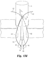
- FIG. 14 is a side representation of an alternative suture closure tool using a pre-curved needle.
- FIG. 15 is an enlarged view of a pre-curved needle for use with the closure tool shown in FIG. 14 .
- FIG. 16 is an enlarged view of a loading tube for introducing the pre-curved needle of FIG. 15 into the suture tool shown in FIG. 14 .
- FIG. 17 is a side view of a suture closure tool according to a further embodiment of the invention using a substantially continuous needle.
- FIG. 18 is a top view of the closure tool shown in FIG. 17 .
- FIG. 19 is a side view of a suture closure tool modified from the embodiment shown in FIG. 17 .
- FIG. 1 One phase of a typical laparoscopic procedure is shown in FIG. 1 .
- a laparoscopic tool L defining a port P is extended into a small incision I.
- the incision passes through multiple tissue layers for access to the patient's abdomen, for instance.
- the laparoscopic tool extends through the skin, subcutaneous and muscle layers, as well as the various fascia layers to provide access to the insufflated abdomen.
- the laparoscopic port P provides a point of entry for a surgical tool, visualization instrumentation and other tools and instruments well known in the field of laparoscopic surgery.
- the present invention contemplates a closure tool 10 that is configured in one embodiment to pass through either the laparoscopic port P, as shown in FIG. 2 , or through the port incision I.
- the tool 10 generally includes an upper cannula 12 and stabilizer elements 14 that are disposed at the distal end of the cannula 12 .
- An actuator 16 is operable to deploy the stabilizer elements 14 into their operative position, as shown in FIG. 4 once the laparoscopic tool L has been withdrawn or removed. In this operative position, the stabilizer elements 14 are displaced outwardly beyond the confines of either the cannula 12 or the laparoscopic tool L. In this position, the entire closure tool 10 can be pulled upward so that the stabilizer elements 14 exert pressure on the innermost fascia F and slightly compress the tissue layers around the incision I.
- the stabilizer elements 14 provide the ability for the surgeon to lift the abdominal wall to clear adjacent organs to decrease the risk of injury to adjacent organs.
- the abdominal wall may be lifted as much as about 2.0 cm. or more which is useful to improve visibility or surgical tool access. This feature is particularly helpful for procedures involving patients with thick subcutaneous tissue layers, such as obese patients.
- the slight compression of the tissue layers caused by pulling the abdominal wall upward using the stabilizer elements 14 may facilitate passage of a suture needle through the tissue.
- the stabilizer elements 14 are pivotably mounted to the upper cannula 12 so that the elements can pivot from their insertion position, as represented in FIGS. 2-3 , and their operable position, as shown in FIG. 4 .
- the elements 14 may be situated at substantially right angles relative to the insertion direction, as depicted in FIG. 4 .
- the elements 14 may be at a non-perpendicular angle in their operable position (see, for instance, FIG. 13 a ).
- the stabilizer elements 14 are mounted to the cannula 12 at a pivot mount 18 .
- the pivot mount is carried at the end of an arm 20 that preferably spans the diameter or across the width of the cannula 12 .
- the actuator 16 is slidably disposed within the upper cannula 12 and is connected to the stabilizer elements by a pair of pull wires 22 .
- the pull wires 22 are engaged to the stabilizer elements 14 at a point 24 remote from the pivot mount 18 so that an upward force exerted on the pull wires 22 by the actuator 16 will cause the elements to pivot about the pivot mount.
- the distal end of the cannula 12 can define opposing openings 25 to receive the inboard portion of the stabilizer elements when they are in their operative position.
- the stabilizer elements can be inserted into the incision I, either directly or through the laparoscopic tool P.
- the closure tool 10 can also be removed with the stabilizer elements 14 in that position.
- the present invention contemplates that the stabilizer elements can be returned to their aligned position depicted in FIG. 5 .
- a torsion spring (not shown) can be disposed within the pivot mount 18 to bias the stabilizer elements 14 to their insertion position shown in FIG. 5 .
- pulling the actuator 16 exerts a moment on the pivoted end of the elements against the biasing force of the torsion spring.
- the actuator 16 can be depressed relative to the cannula 12 so that the torsion force of the spring naturally tends to pivot the stabilizer elements 14 to the insertion/removal position.
- the stabilizer elements 14 ′ are pivotably mounted by pivot arms 20 ′ to pivot mounts 18 ′ defined on the interior of the upper cannula 12 ′.
- the actuator 16 is connected by push rods 22 ′ to the stabilizer elements at mounting points 24 ′.
- the push rods 22 ′ are generally rigid but pivotably mounted at their ends to the actuator 16 and the mounting points 24 ′.
- the actuator 16 is pushed downward, as indicated by the arrow, the stabilizer elements 14 ′ swing outward into the operative position shown in FIG. 4 .
- the actuator is pulled upward, which in turn pivots the elements 14 ′ in the counter-direction until they are aligned with the cannula 12 ′, as shown in FIG. 6 .
- the cannula 50 carries a tube 52 that supports an actuator plunger 55 .
- the proximal end of the tube 52 may be flared (not shown) to provide a finger gripping location to facilitate depressing the plunger 55 and to provide a purchase point to pull or retract the tool 50 , as described herein.
- the plunger is connected to actuator wires 54 that are fixed at a mounting point 58 to each of the stabilizer elements 56 .
- the stabilizer elements 56 are pivotably mounted to a pivot mount 60 that extends from the base of the cannula 50 .
- the pivot mount 60 is situated between opposite legs 61 projecting from the cannula.
- the stabilizer elements 56 include pivot arms 62 that are mounted on an axle 63 that extends between and is supported by the legs 61 at the pivot mount.
- the stabilizer elements 56 start in their retracted position shown in FIG. 7 a to permit insertion through the incision. Once the elements 56 are visualized beneath the tissue layers, the actuator plunger 55 is depressed so that the actuator wires 54 push the stabilizer elements 56 outward about the pivot mount 60 , as shown in FIG. 7 b .
- the actuator wires are bendable but stiff enough to permit transmission of an axial force from the plunger 55 through the wires against the free ends of the stabilizer elements 56 .
- a locking pin 64 can be extended through aligned pin bores 65 , 66 and 67 in the upper cannula 50 , tube 52 and actuator plunger 55 , respectively.
- the pin thus holds the actuator, and therefore the stabilizer elements, in the position shown in FIG. 7 c so that the stabilizer elements can be pulled upward into the tissue, as described above.
- the locking pin 64 is removed and the actuator plunger 55 is either pushed further downward, in which case the elements 56 pivot downwardly, or the plunger is pulled back, in which case the elements 56 pivot upward back to their original position shown in FIG. 7 a . It can be appreciated that in this embodiment, as well as in the embodiment of FIG. 6 , no torsion spring or biasing element is required.
- a cannula 30 includes downwardly projecting legs 35 that support a pivot mount 34 for the stabilizer elements 32 .
- the elements include pivot arms 36 that are supported on an axle 37 supported by the legs 35 .
- a torsion spring 38 may be disposed between the pivot arms 36 of the two stabilizer elements 32 , or each element can include a torsion spring disposed between it and the pivot mount.
- the torsion spring 38 is configured to bias the stabilizer elements 32 to their deployed position, as shown in FIG. 4 .
- the stabilizer elements 32 are held in their insertion position, shown in FIG. 8 , by locking wires 42 that fit within recesses 40 in the tips of the elements.
- the locking wires 42 are connected to an actuator 44 that may be retracted or moved upwardly to release the locking wires 42 from the recesses 40 .
- the torsion spring 38 causes the stabilizer elements 32 to automatically pivot about the pivot mount 34 .
- a movable limit stop may be incorporated into the pivot mount 34 to hold the stabilizer elements in the deployed position. These limit stops may then be removed to allow the elements to continue to pivot until they are in line with the cannula 30 to permit removal of the closure tool.
- the closure tool 70 includes a body or cannula 71 that is sized to fit within the incision or through the laparoscopic tool P.
- the cannula 71 is formed by an annular wall 72 ( FIG. 12 c ) that is preferably formed or molded in a medical grade material.
- the body 71 as well as most of the components of the closure tool 70 , is formed of an inexpensive, readily disposable material, such as a medical grade plastic.
- the closure tool 70 includes stabilizer elements 74 that are configured to bear against the inner fascia of the patient's tissue from within the insufflated surgical site and to provide pressure to compress the tissue during suture insertion.
- the stabilizer elements 74 are further configured to move from the compact insertion position shown in FIGS. 9 a - b , to the extended operating position shown in FIGS. 10 a - b , to the removal position depicted in FIGS. 12 a - b .
- An actuator 76 is provided to accomplish moving the stabilizer elements between the three positions.
- the stabilizer elements are supported on the cannula 71 at a pivot mount 78 .
- the pivot mount 78 is offset from the cannula by support legs 79 .
- An axle 80 extends between the legs 79 to support the stabilizer elements.
- Each stabilizer element 74 includes a wing 82 that is supported on a pivot hub 84 defining an axle bore 85 ( FIG. 11 a ) for mounting on the axle 80 .
- a torsion spring 88 is disposed on the axle 80 between the two pivot hubs 84 . The ends of the torsion spring 88 may be embedded or locked within the hubs in a known manner that is sufficient to reliably rotate the two wings 82 of the stabilizer elements 74 .
- the torsion spring 88 is calibrated to fully rotate both wings to the removal position shown in FIGS. 12 a - b , in the absence of any restraint against rotation of the wings.
- a single torsion spring 88 is provided between the two hubs 84 , each hub can be provided with its own torsion spring that operates between the hub and a corresponding support leg 79 .
- a single torsion spring may be preferred for ease of assembly and reduced space requirements.
- the actuator 76 restrains the two wings 82 from pivoting under the influence of the torsion spring 88 .
- the actuator 76 includes an actuator bar 90 that passes diametrically through the cannula 71 , and more specifically through opposite actuator channels 98 defined in the cannula wall 72 .
- Knobs 91 at the opposite ends of the bar 90 retain the bar within the channels 98 and provide for manual engagement to operate the actuator 76 .
- the knobs 91 are grasped between the thumb and forefinger to manipulate the actuator bar 90 within the two channels 98 .
- a pair of flexible cables 93 are fastened at one end to the actuator bar 90 and at the opposite end to the spool hub 95 of a corresponding pivoting wing 82 .
- the cables 93 are configured to be wound around a respective spool hub 95 when the stabilizer elements 74 are rotated from their insertion position shown in FIGS. 9 a - b to their removal position illustrated in FIGS. 12 a - b .
- the torsion spring 88 is operable to rotate each pivot hub 84 and associated spool hub 95 to gradually wind the corresponding flexible cable onto the spool.
- the torsion spring rotates the spool hubs to take up the slack in the cables 93 , and at the same time pivot the wings 82 to the operative position.
- the actuator bar 90 is manually moved from the detent 102 to the detent 104 at the end of the actuator channel 98 .
- the slack in the cables 93 is again taken up by rotation of the spool hubs 95 under the influence of the torsion spring 88 .
- the stabilizer elements 74 can be returned to their initial closed position ( FIGS. 9 a - b ) by pulling the actuator bar up the channel 98 to the fist detent 100 . This movement unwinds the cables 93 from the corresponding spool hubs 95 causing the hubs to rotate against the torsion springs.
- the actuator channel 98 includes a ramp portion 101 between the first detent 100 and the second detent 102 , as well as a comparable ramp portion 103 between the second and third detents 102 , 104 , respectively.
- the ramp portions are inclined upward or away from the first and second detents so that the actuator bar 90 must be pulled upward to dislodge the bar from the corresponding detent.
- the closure tool 70 includes means for stabilizing the tool relative to the tissue and incision.
- the stabilizer elements 74 provide means for lifting the tissue layers away from intra-peritoneal structures. As explained above, lifting the tissues away from organs, for instance, may help in visualizing the surgical site as well as help in providing clear access to internal body structures.
- the stabilizer elements also provide some compression of the tissue around the incision, which can facilitate passage of a suture needle through the tissue.
- the closure tool thus provides means for directing a suture through the tissue and capturing the suture so that when the tool is removed the ends of the suture are accessible to tie off and close the incision.
- the cannula wall 72 defines a pair of diametrically opposite needle guide channels 108 , as best seen in FIGS. 10 b and 12 c .
- the guide channels are arranged so that a straight needle passing through the channels will approach the tip of each pivoting wing 82 when the wings are in their operative position shown in FIG. 10 b.
- the guide channels define an entry opening 109 at the side of the cannula 71 that is positioned to reside sufficiently above the skin of the patient when the closure tool 70 is in its operative position.
- the opening 109 can be conical to facilitate introduction of a suture needle into the channel.
- Each channel 108 further defines an exit opening 111 at the base of the cannula and aligned with the top of the corresponding pivoting wing 82 in the operative position of FIG. 10 b . It is understood that the guide channels 108 and their corresponding entry and exit openings are aligned to avoid encroachment with the other components of the closure tool 70 .
- the exit openings are also preferably aligned so that a suture needle exiting the channels will contact the fascia of the incision below the skin layer.
- the exit openings 111 are arranged so that the suture needle will first penetrate the subcutaneous tissue SC ( FIG. 1 ).
- the support legs 79 for the pivot mount 78 supporting the extended wings 82 have a length approximately equal to the nominal thickness of the muscle layer M and fascia F beneath the subcutaneous tissue SC. It can be appreciated that when the closure tool 70 is in its operative position, a portion of the cannula 71 is disposed within the upper portion of the incision I.
- the needle guide channels 108 define a suture slot 113 ( FIG. 12 c ) along the length of each channel.
- the suture slot 113 is narrower than a suture needle, but sufficiently wide to allow a suture to pass through as the suture needle is advanced along the channel.
- the suture slot 113 thus facilitates accessing the free ends of the suture once the suture has passed through the tissue layers and the closure tool removed from the incision.
- the cannula 71 is preferably molded from a medical grade plastic.
- the needle guide channels 108 can be integrally formed with the wall 72 with a web 115 spanning the space between the wall and the channels.
- the webs 115 support the guide channels so that they hold their position relative to the extended pivoting wings 82 .
- each suture 122 is carried by a needle tip 120 , as shown in FIG. 13 a .
- the needle tip 120 is essentially simply the tip of a suture needle, absent the needle shaft.
- the suture 122 is fastened to or held by the needle tip in a known manner, such as by crimping the suture within a slot formed in the tip.
- the suture must be fastened to the needle tip in a manner that prevents its separation from the needle tip 120 during use of the closure tool 70 . It is understood that once the ligature loop has been completed at the incision the suture can be cut at the needle tip, leaving a free end of the suture.
- the invention contemplates a needle driver 124 that carries and propels the needle tip through the guide channels 108 and through the tissue layers.
- the needle driver 124 can be provided with a bore 125 to removably receive a base portion 126 of the needle tip.
- Other methods for removably engaging the needle tip 120 to the needle driver 124 are contemplated provided that the driver can be easily removed from the needle tip once the needle tip and suture has been passed through the tissue layers.
- the closure tool 70 thus provides means for directing a suture needle carrying a suture toward the extended wings 82 .
- the wings 82 are themselves provided with means for capturing the suture needle, and ultimately one end of the suture.
- the tip of each pivoting wing 82 includes a capturing device 130 , as shown in FIG. 1 a , that is configured to capture the needle tip 120 and hold it from retrograde movement as the wings are pivoted to their removal position of FIGS. 12 a - b and as the closure tool 70 is removed from the incision.
- the capturing device includes a guide ring 132 that is configured to guide the needle tip toward the center of the capturing device 130 .
- the device includes a resilient flap structure 134 at the center of the guide ring with a center opening 136 to receive the point of the needle tip.
- the guide ring aligns the point of the needle tip with the center opening 136 .
- the guide ring is preferably slightly conical to direct the needle tip to the center opening even if the needle tip contacts the wing 82 slightly offset.
- a capturing device 140 is provided as shown in FIG. 11 b that is rectangular rather than circular in configuration.
- the device includes a series of resilient flaps 142 with separation lines 143 providing areas in which the flaps can be separated for passage of the needle tip. These flaps 142 operate like the retention flap 134 described above to capture the needle tip and prevent its retrograde movement. In both embodiments of FIG. 1 a and FIG. 11 b the corresponding retention flaps hold the needle tip as the needle driver 124 is disengaged from the needle tip.
- each pivoting wing 82 can be provided with a gripping feature, such as the ridges 148 depicted in FIG. 11 b .
- This gripping feature may enhance the engagement of the stabilizer elements with the tissue as the wings are pulled upward to exert pressure on the body tissue.
- the material of the gripping feature, or ridges 148 must be capable of achieving solid purchase on the relatively slick surface of the fascia F.
- the gripping feature is formed of a rubber or a SILASTIC® material.
- FIGS. 13 a - e the use of the closure tool 70 can be understood.
- the wings 82 have been deployed into their operative position and the closure tool 70 pulled back to slightly compress the tissue layers.
- the closure tool is situated so that the exit opening of each needle guide channel 108 is aligned so that the needle tip 120 can pass directly into a portion of the subcutaneous tissue layer from inside the incision.
- the closure tool may be positioned to close the anterior fascia, the posterior fascia, or both.
- the tubular body 71 of the closure tool 70 presents an outer diameter that is larger than the effective diameter of the incision I.
- the body tissue at the incision wall tend to “flow” into the space between the tubular body 71 and the wings 82 .
- a similar effect may be achieved if the tool 70 is deployed through a trocar or laparoscopic port P ( FIG. 1 ) with a diameter greater than the effective diameter of the incision I. This tissue ingress enhances the ability to pierce the tissue layers with the needle tip 120 , particularly for plural needle paths and suture sites.
- a needle tip 120 is loaded onto a needle driver 124 , with the suture 122 fixed to the needle tip and the free end of the suture disposed outside the wound.
- the needle driver is then pushed toward the incision I to penetrate the tissue layers.
- the needle tip is aimed toward the capturing device 130 of the wing 82 .
- the needle tip 120 has traversed the capturing device 120 and is held in position against its removal.
- the slight compression of the body tissue facilitates penetration of the needle tip so that the tip should be substantially aligned with the capturing device 130 when it reaches the wing 82 .
- a needle driver 124 is also used to drive a needle tip into the capturing device on the opposite wing 82 so that a suture 122 has been threaded through opposite sides of the incision I.
- each suture 122 may be temporarily positioned within the needle guide channels 108 or may be loose adjacent the cannula 71 ; however, the distal portion of the suture has been driven through the tissue around the incision.
- the wings are moved to their removal position, illustrated in FIG. 13 d , in the manner described above. Specifically, the actuator 76 is moved to the lowest detent 104 so that the torsion spring can unwind and rotate the wings 82 until they are generally aligned with the longitudinal axis of the cannula 71 . It is understood that as the wings rotate downwardly, they pull each suture 122 with them so that excess suture 123 is drawn through the closure site. At the same time, the cannula 71 may be pushed slightly into the incision to draw additional suture material into the site.
- the entire closure tool 70 may be removed from the incision, as shown in FIG. 13 e .
- the excess suture 123 is pulled back through the incision to form a ligature loop.
- the suture can be cut at the needle tip 120 so that the free ends of each suture 122 are accessible outside the incision.
- the two sutures can then be tied off in a conventional manner to close the incision, and more particularly to close the fascial layers of the incision.
- the closure tool 70 provides an easy and efficient mechanism for forming a subcutaneous ligature loop and closing an incision, especially in the abdomen.
- the device provides means for driving two sutures through the tissue without requiring direct vision of the process from within the body cavity. However, it is preferable that the process be visualized and that the position of the sutures be verified under direct vision before the opening is closed. In typical surgical practice, only two sutures are required to completely close an incision, so only a single operation of the tool 70 is required. However, if desired, additional sutures may be introduced at the incision.
- the closure tool 70 may be “reloaded” with a second set of needle tips 120 and sutures 122 and the tool repositioned within the incision I.
- an additional pre-loaded closure tool can be passed through the same incision with the sutures 122 in the position shown in FIG. 13 e .
- the second closure tool placement may be aligned with the wings 82 at ninety degrees to the position of the wings of the first tool to pass two additional sutures at the ninety degree interval.
- the same procedure outlined in FIGS. 13 a - e may be followed with this additional tool to provide four sutures to close the incision.
- each closure tool 70 is disposable and is intended to be discarded after each patient use once the sutures have been placed.
- Each closure tool is preferably provided pre-loaded—i.e., with each needle tip engaged to a corresponding needle driver, and each needle driver positioned within a corresponding needle guide channel.
- the needle driver can be configured to combine the driver for the suture needles on the opposite sides of the tool into a single driver so that only a single movement of the needle driver is necessary to penetrate the tissue and lodge each needle tip into a corresponding capturing device.
- a closure tool 150 includes a cannula 151 that defines a guide channel 152 for receiving a suture needle.
- the closure tool further includes stabilizer elements 156 that are connected to the cannula 151 by way of a pivot mount 158 .
- the closure tool 150 can be constructed in a manner similar to the tool 70 described above.
- the stabilizer elements can include a torsion spring to bias the elements to their retraction position (see FIG. 13 d ).
- the tool 150 may also incorporate an actuator similar to the actuator 76 of the closure tool 70 (see FIG. 12 a ).
- the closure tool 150 incorporates a needle capture device 160 in the body of the cannula, as shown in FIG. 14 .
- the capture device 160 may be configured similar to the capture devices 130 and 140 shown in FIGS. 11 a and 11 b , respectively.
- the capture device 160 may include resilient flaps 161 that separate as the needle tip passes into the device, and then collapse about the needle hub to hold the needle tip within the cannula 151 .
- the closure tool 150 further includes a guide tube 154 that extends from the guide channel to a corresponding pivoting wing 156 .
- the wing supports the guide tube so that the end of the tube opens upward toward the tissue when the wing is in its operative position shown in FIG. 14 .
- the guide tube is formed of a resilient, bendable material that can be essentially folded upon itself when the wing is in its closed or insertion position (see e.g. FIG. 9 b ), or fully unfolded when the wings are in their removal position (see e.g., FIG. 12 b ).
- the guide tube is formed of a medical grade plastic.
- the guide channel 152 and guide tube 154 define a passageway along which a curved needle assembly 162 passes.
- the needle assembly includes a needle tip 164 to which is attached one end of a suture 166 , as shown in FIG. 15 .
- the needle tip and suture arrangement may be the same as the needle tip and suture described above.
- the needle assembly 162 further includes a pre-curved needle pusher 168 .
- the needle pusher is formed of a material that can be pre-formed at a particular radius of curvature, as reflected in FIG. 15 , but that is flexible enough to be initially straightened to pass through the guide channel 152 .
- the needle driver 168 flattens as it is pushed through the guide channel 152 and the upper portion of the guide tube 154 . As the needle driver progresses along the guide tube it continues to follow the bend in that tube as well as the straight section of the guide tube along the length of the stabilizer element 156 . Once the needle driver exits the guide tube 154 beneath the tissue layers, the driver starts to assume its pre-curved shape. As the needle driver and the needle tip it carries are pushed further into the tissue the driver continues to assume its pre-curved shape. The curved shape of the needle driver 168 is configured so that the needle tip 164 is guided toward the capturing device 160 on the outer surface of the cannula 151 .
- the needle driver can include a straight section 170 ( FIG. 16 ) at the proximal portion of the driver.
- the needle assembly 162 may be initially provided within a straight sheath 172 .
- the sheath 172 may mate with the guide channel 152 to facilitate introduction of the pre-curved portion of the needle driver 168 into the guide channel.
- the guide channel 152 and guide tube 154 are continuous—i.e., they are not provided with a suture slot, like the slot 113 of the closure tool 70 described above.
- the suture 166 will pass through the channel 152 and tube 154 even when the closure tool 150 is removed form the incision.
- One end of the suture will be retained along with the needle tip 164 in the capturing device 160 as the tool is removed from the incision.
- the opposite end of the suture remains free because the suture will be pulled through the tissue as the captured end is pulled with the closure tool. Once the tool has been completely removed from the incision the suture can be cut at the end of the guide tube 154 and at the capturing device 160 .
- the free ends of the sutures can be tied off in a conventional manner.
- the tool 150 can be discarded.
- a second set of pre-loaded pre-curved needle assemblies can be loaded into the tool and the tool re-introduced into the incision but rotated by ninety degrees relative to the sutures already in position.
- each suture is passed through tissue at one side of the incision and then drawn through the incision itself, as demonstrated by the ligature loops shown in FIG. 13 e .
- a single suture passes through tissue layers on opposite sides of the incision, with the suture spanning the incision within the body cavity.
- a closure tool 180 is provided with a continuous needle track 188 which guides a pre-curved needle 194 that is wholly contained within the tool 180 , as shown in FIGS. 17-18 .
- the tool includes a pair of stabilizer elements 182 that can be rotated from a closed position to an operative position to a removal position.
- the actuators of the prior embodiments may be used to extend and retract the elements 182 ; however, in the illustrated embodiment of FIG. 17 a rack and pinion gear approach is utilized.
- the pivot mounted end of the stabilizer elements 182 forms a pinion gear 183 .
- a linear rack gear 185 extends through the closure tool 180 and includes rack threads that engage the pinion gear threads.
- An actuator knob 186 passes through a slot in the tool 180 so that the knob can be used to raise and lower the rack gear 185 .
- the rack gear As the rack gear is raised, it rotates the pinion gears 183 so that the stabilizer elements 182 swing away from the body of the tool 180 .
- the slot (not shown) in the closure tool 180 can incorporate detents, like the actuator channel 98 of the tool 70 shown in FIG. 10 b , so that the actuator rack gear may be moved in indexed fashion between the three functional positions of the stabilizer elements 182 .
- the closure tool 180 defines a continuous needle track 188 that winds around the circumference of the tool and along the length of the tool.
- the needle track is preferably configured to accommodate the pre-curved configuration of the needle 194 .
- the needle track can gradually spiral up the length of one side of the tool 180 and spiral down the opposite side.
- the needle track traverses the body of the tool 180 at an exit opening 195 and an entrance opening 198 substantially opposite the exit opening.
- the entrance opening 198 is larger than the exit opening and forms a taper to the needle track. This feature of the entrance opening helps guide the pre-curved needle 194 back into the tool 180 once it has passed through the tissue layers on both sides of the incision, as indicated by the dashed arrows in FIG. 17 .
- the needle track 188 is accessed through a pair of openings 190 and 192 .
- the first opening 190 provides access to the needle 194 to engage a suture 191 to the needle.
- the needle can incorporate an eye through which the suture may be threaded in a known manner. Alternatively, the suture may be crimped onto the needle or otherwise fastened to the needle so that it can be drawn through the tissue layers with the needle.
- the opposite opening 192 allows access to the needle after the suture has been passed through the tissue and has been pulled through the needle track 188 . The suture can be cut from the needle at this location before or after the closure tool has been removed from the incision. At a minimum, the second opening 192 allows for verification that the suture has been drawn through the tissue layers and is in position to close the incision.
- the pre-curved needle 194 is curved so that it follows its pre-defined curvature as it exits the needle track 188 through the exit opening 195 , as shown in FIG. 17 .
- the needle As the needle continues to curve through the tissue layers, it is self-directed to a guide slot 196 formed in the body of the tool 180 .
- the guide slot includes an angled upper wall 197 that collects the needle tip even if it is slightly offset on its path through the tissue.
- the guide slot 196 is also open at its lower end so that a suture passing under the angled upper wall 197 is not trapped within the tool 180 when it is removed.
- the guide slot 196 is open at its lateral face so that the suture can be dislodged from the slot by a slight manipulation of the closure tool 180 as it is being removed from the incision.
- the pre-curved needle is mechanically driven by a needle drive assembly 200 .
- the drive assembly 200 includes a pair of drive rollers 202 that are arranged to contact the needle 194 at opposite sides of the closure tool 180 .
- An idler roller 204 is connected to an externally accessible crank 206 . Rotation of the idler roller rotates the two drive rollers in opposite directions, with one roller 202 a propelling the needle up through needle track 188 and the other roller 202 b pushing the needle down through the track toward the exit opening 195 .
- the rollers may be formed of a hard rubber that exhibits sufficient friction to propel the needle along the track. It can be appreciated that the needle track 188 defines openings at the rollers so the rollers can directly contact the needle within the track.
- the pre-curved needle has a length that permits at least one of the rollers 202 to be in driving contact with the needle 194 at all times. Since the pre-curved needle exist and re-enters the needle track, it must have enough length so that the needle tip encounters one of the rollers 202 a on its return to the tool 180 before the tail end of the needle loses contact with the other driver roller 202 b . At the same time, the needle track 188 is sized relative to the length of the needle so that the needle can be entirely contained within the closure tool 180 when the tool is inserted into or removed from the incision.
- a drive assembly 212 configured like the drive assembly 200 , can be situated at the base of a closure tool 210 , as shown in FIG. 19 .
- the tool does not define a continuous needle track, but instead a discharge track 214 and a retrieval track 216 .
- the drive assembly 212 is disposed between the two tracks to propel or pull a pre-curved needle 220 in the same circular path through the tissue layers at the opposite sides of the incision.
- a plunger, actuator knob and rotating crank have been disclosed for controlling the actuation of the stabilizer elements and for deploying the suture needles and needle tips.
- Other means for controlling the actuation and movement of these components are contemplated, including reusable devices that are configured to mate with the various closure tools.
- one alternative is to implement a squeeze handle to advance the suture needles through the tissue.
- the squeeze handle would include a fixed handle arm engaged to the tubular body of the closure tool and a movable handle arm connected to the needle driver in a suitable manner.
- the movable handle arm may be connected to an end of the needle driver 124 shown in FIG. 13 a through an appropriate linkage so that manually squeezing the handle drives the needle tip and suture the appropriate distance through the tissue.
- the actuation of the stabilizer elements may be initiated by a manual trigger through a spring-biased element adapted to extend the stabilizer wings to their operative position.
- the trigger actuation for the stabilizer elements is combined with the squeeze handle actuation for the suture needle driver to provide single-handed operation of the closure tool. Since the closure tool is preferably disposable, the trigger and squeeze handle actuators may be provided separately with means for engaging the actuators to the closure tool. After each use, the separate actuator device would be cleaned and sterilized for use in another procedure.
- the closure tools may incorporate one or more stabilizer elements or wings, with an appropriate number of needle guide channels.
- a single stabilizer wing may be configured to rotate relative to the tubular body of the closure tool to align with a plurality of needle guide channels disposed around the circumference of the body.
- closure tool has been described as being used to close a surgical incision.
- the closure tools of the present invention may have application in closing non-surgical wounds as well.
- the stabilizer elements may be used to help retract the fascia away from internal organs for better visualization to determine whether any organs require repair.
- the closure tool can then be used to close the wound in the same manner described above.
Abstract
Description
Claims (17)
Priority Applications (4)
| Application Number | Priority Date | Filing Date | Title |
|---|---|---|---|
| US11/176,616 US8992549B2 (en) | 2004-08-05 | 2005-07-07 | Laparoscopic port site closure tool |
| US14/672,924 US9775593B2 (en) | 2004-08-05 | 2015-03-30 | Laparoscopic port site closure tool |
| US15/722,576 US11154285B2 (en) | 2004-08-05 | 2017-10-02 | Laparoscopic port site closure tool |
| US17/509,902 US20220039783A1 (en) | 2004-08-05 | 2021-10-25 | Laparoscopic port site closure tool |
Applications Claiming Priority (2)
| Application Number | Priority Date | Filing Date | Title |
|---|---|---|---|
| US59879804P | 2004-08-05 | 2004-08-05 | |
| US11/176,616 US8992549B2 (en) | 2004-08-05 | 2005-07-07 | Laparoscopic port site closure tool |
Related Child Applications (1)
| Application Number | Title | Priority Date | Filing Date |
|---|---|---|---|
| US14/672,924 Continuation US9775593B2 (en) | 2004-08-05 | 2015-03-30 | Laparoscopic port site closure tool |
Publications (2)
| Publication Number | Publication Date |
|---|---|
| US20060030868A1 US20060030868A1 (en) | 2006-02-09 |
| US8992549B2 true US8992549B2 (en) | 2015-03-31 |
Family
ID=35758394
Family Applications (4)
| Application Number | Title | Priority Date | Filing Date |
|---|---|---|---|
| US11/176,616 Active 2031-10-22 US8992549B2 (en) | 2004-08-05 | 2005-07-07 | Laparoscopic port site closure tool |
| US14/672,924 Active 2026-01-05 US9775593B2 (en) | 2004-08-05 | 2015-03-30 | Laparoscopic port site closure tool |
| US15/722,576 Active 2026-09-09 US11154285B2 (en) | 2004-08-05 | 2017-10-02 | Laparoscopic port site closure tool |
| US17/509,902 Pending US20220039783A1 (en) | 2004-08-05 | 2021-10-25 | Laparoscopic port site closure tool |
Family Applications After (3)
| Application Number | Title | Priority Date | Filing Date |
|---|---|---|---|
| US14/672,924 Active 2026-01-05 US9775593B2 (en) | 2004-08-05 | 2015-03-30 | Laparoscopic port site closure tool |
| US15/722,576 Active 2026-09-09 US11154285B2 (en) | 2004-08-05 | 2017-10-02 | Laparoscopic port site closure tool |
| US17/509,902 Pending US20220039783A1 (en) | 2004-08-05 | 2021-10-25 | Laparoscopic port site closure tool |
Country Status (1)
| Country | Link |
|---|---|
| US (4) | US8992549B2 (en) |
Cited By (24)
| Publication number | Priority date | Publication date | Assignee | Title |
|---|---|---|---|---|
| US20140180311A1 (en) * | 2012-12-21 | 2014-06-26 | Abbott Cardiovascular Systems, Inc. | Articulating suturing device |
| US20150201920A1 (en) * | 2004-08-05 | 2015-07-23 | Teleflex Medical Incorporated | Laparoscopic port site closure tool |
| US9320522B2 (en) | 2000-12-07 | 2016-04-26 | Integrated Vascular Systems, Inc. | Closure device and methods for making and using them |
| US9332976B2 (en) | 2011-11-30 | 2016-05-10 | Abbott Cardiovascular Systems, Inc. | Tissue closure device |
| US9398914B2 (en) | 2003-01-30 | 2016-07-26 | Integrated Vascular Systems, Inc. | Methods of use of a clip applier |
| US9402625B2 (en) | 2000-09-08 | 2016-08-02 | Abbott Vascular Inc. | Surgical stapler |
| US9414820B2 (en) | 2009-01-09 | 2016-08-16 | Abbott Vascular Inc. | Closure devices, systems, and methods |
| US9414824B2 (en) | 2009-01-16 | 2016-08-16 | Abbott Vascular Inc. | Closure devices, systems, and methods |
| US20160278763A1 (en) * | 2015-03-24 | 2016-09-29 | Richard B. BEAVEN MD | Laparoscopic wound closure device |
| US9486191B2 (en) | 2009-01-09 | 2016-11-08 | Abbott Vascular, Inc. | Closure devices |
| US9498196B2 (en) | 2002-02-21 | 2016-11-22 | Integrated Vascular Systems, Inc. | Sheath apparatus and methods for delivering a closure device |
| US9554786B2 (en) | 2000-12-07 | 2017-01-31 | Integrated Vascular Systems, Inc. | Closure device and methods for making and using them |
| US9585647B2 (en) | 2009-08-26 | 2017-03-07 | Abbott Laboratories | Medical device for repairing a fistula |
| US9962144B2 (en) | 2006-06-28 | 2018-05-08 | Abbott Laboratories | Vessel closure device |
| US9980728B2 (en) | 2002-06-04 | 2018-05-29 | Abbott Vascular Inc | Blood vessel closure clip and delivery device |
| US10085753B2 (en) | 2005-07-01 | 2018-10-02 | Abbott Laboratories | Clip applier and methods of use |
| US10111664B2 (en) | 2000-01-05 | 2018-10-30 | Integrated Vascular Systems, Inc. | Closure system and methods of use |
| US10251638B2 (en) | 2016-04-01 | 2019-04-09 | Ethicon Llc | Surgical access devices having a cannula sidewall seal with a variable cross-sectional thickness |
| US10307144B2 (en) | 2014-02-07 | 2019-06-04 | Medeon Biodesign, Inc. | Suture delivery device for suturing tissue |
| US10327761B2 (en) | 2014-02-07 | 2019-06-25 | Medeon Biodesign, Inc. | Suture delivery device for suturing tissue |
| US10398418B2 (en) | 2003-01-30 | 2019-09-03 | Integrated Vascular Systems, Inc. | Clip applier and methods of use |
| US10413295B2 (en) | 2008-05-16 | 2019-09-17 | Abbott Laboratories | Engaging element for engaging tissue |
| US10631840B2 (en) | 2015-11-25 | 2020-04-28 | Talon Medical, LLC | Tissue engagement devices, systems, and methods |
| EP4190246A1 (en) | 2021-12-06 | 2023-06-07 | Universität Zürich | Device for closing a tissue opening |
Families Citing this family (48)
| Publication number | Priority date | Publication date | Assignee | Title |
|---|---|---|---|---|
| EP1876967A2 (en) * | 2005-04-19 | 2008-01-16 | Vladimir Shpaichler | Device for wound suturing and hemostasis in the thoracic and the abdominal wall mainly in endoscopic operations |
| US8545522B2 (en) | 2005-04-19 | 2013-10-01 | Vladimir Shpaichler | Device for wound suturing and hemostasis in the thoracic and the abdominal wall mainly in endoscopic operations |
| US20080033459A1 (en) * | 2006-08-03 | 2008-02-07 | Surgsolutions, Llp | Suturing apparatus for closing tissue defects |
| US9107656B2 (en) * | 2006-10-20 | 2015-08-18 | St. Jude Medical, Cardiovascular Division, Inc. | Internal suturing device leg suspension system and method of use |
| US8834493B2 (en) * | 2006-10-20 | 2014-09-16 | St. Jude Medical, Cardiology Division, Inc. | Device and method for vascular closure |
| WO2009002390A1 (en) | 2007-06-08 | 2008-12-31 | Thomas Hsu | Devices and methods for closure of wounds |
| US10307041B2 (en) | 2007-06-08 | 2019-06-04 | Medeon Biodesign, Inc. | Lens cover modification |
| CN102065776B (en) * | 2008-07-02 | 2014-03-12 | A.H.比利私人有限公司 | Apparatus of laparoscopic port site suture |
| US8562630B2 (en) * | 2008-07-18 | 2013-10-22 | Richard Campbell | Suture instrument and method |
| JP5720031B2 (en) * | 2009-01-12 | 2015-05-20 | テレフレックス メディカル インコーポレイテッドTeleflex Medical Incorporated | Apparatus and method for tissue closure |
| US8591529B2 (en) | 2009-10-01 | 2013-11-26 | Covidien Lp | Wound closure device including direct-driven needle |
| US20110082475A1 (en) * | 2009-10-01 | 2011-04-07 | Tyco Healthcare Group Lp | Wound closure device including ferrule ejector system |
| US8435252B2 (en) * | 2009-11-11 | 2013-05-07 | Covidien Lp | Wound closure device |
| US9855031B2 (en) * | 2010-04-13 | 2018-01-02 | Neosurgical Limited | Suture delivery system |
| EP2579786B1 (en) | 2010-06-09 | 2017-11-01 | C.R. Bard Inc. | Instruments for delivering transfascial sutures and transfascial suture assemblies |
| US8906042B2 (en) | 2010-07-29 | 2014-12-09 | Covidien Lp | Wound closure device including mesh barrier |
| US20130035702A1 (en) * | 2011-08-04 | 2013-02-07 | Suture Ease, LLC | Dual insufflation and wound closure devices and methods |
| US8979747B2 (en) | 2011-09-23 | 2015-03-17 | Cooper Surgicalk, Inc. | Endoscopic ports and related kits and methods |
| US9826972B2 (en) | 2011-10-24 | 2017-11-28 | C.R. Bard, Inc. | Instruments for delivering transfascial sutures, transfascial suture assemblies and methods of transfascial suturing |
| US9924938B2 (en) * | 2011-11-07 | 2018-03-27 | C.R. Bard, Inc. | Instruments for delivering transfascial sutures and methods of transfascial suturing |
| US9149272B2 (en) * | 2011-12-27 | 2015-10-06 | Coopersurgical, Inc. | Suture passer guides and related kits and methods |
| US9782163B2 (en) | 2012-01-04 | 2017-10-10 | Teleflex Medical Incorporated | Apparatus and methods for tissue closure |
| EP2825101A4 (en) | 2012-03-13 | 2015-12-16 | Suture Ease Llc | Needle and snare guide apparatus for passing suture |
| US9066717B2 (en) * | 2012-05-18 | 2015-06-30 | Coopersurgical, Inc. | Suture passer guides and related kits and methods |
| US9271721B2 (en) * | 2012-12-19 | 2016-03-01 | Cook Medical Technologies Llc | Port closure device |
| US9265488B2 (en) | 2013-03-13 | 2016-02-23 | Medtronic Vascular, Inc. | Suturing device and method for sealing an opening in a blood vessel or other biological structure |
| CN105163674B (en) * | 2013-03-13 | 2018-04-17 | 美敦力瓦斯科尔勒公司 | Stitching devices and method for the opening in seal blood vessels or other biological structures |
| US9314229B2 (en) | 2013-03-13 | 2016-04-19 | Medtronic Vascular, Inc. | Suturing device and method for sealing an opening in a blood vessel or other biological structure |
| US9510823B2 (en) | 2013-08-02 | 2016-12-06 | Covidien Lp | Devices, systems, and methods for wound closure |
| WO2015047654A1 (en) * | 2013-09-25 | 2015-04-02 | Medtronic Vascular Inc. | Suturing device for sealing an opening in a blood vessel or other biological structure |
| EP3079603B1 (en) * | 2013-12-09 | 2024-02-21 | Teleflex Medical Incorporated | Laparoscopic fascial closure system |
| CN103876796B (en) * | 2014-04-03 | 2016-03-23 | 郑州迪奥医学技术有限公司 | Internal abdominal wall anastomat |
| US10149678B1 (en) * | 2015-06-17 | 2018-12-11 | Ethicon Llc | Suturing instrument with elastomeric cleat |
| US10271838B2 (en) | 2015-07-21 | 2019-04-30 | Artisan Medical Supply Corporation | Laparoscopic suturing guide |
| CN105266859A (en) * | 2015-11-23 | 2016-01-27 | 黄盛� | Minimally-invasive fascia closer |
| WO2017182492A1 (en) * | 2016-04-19 | 2017-10-26 | Neosurgical Limited | Suture delivery system |
| WO2018031804A1 (en) * | 2016-08-11 | 2018-02-15 | Medeon Biodesign, Inc. | Suture delivery device for suturing tissue |
| US10709444B2 (en) * | 2017-01-24 | 2020-07-14 | Allergan Industrie Sas | Thread insertion devices |
| US11389192B2 (en) * | 2017-06-29 | 2022-07-19 | Cilag Gmbh International | Method of suturing a trocar path incision |
| CN107582116B (en) * | 2017-09-01 | 2018-11-09 | 佛山市优特医疗科技有限公司 | A kind of operative incision inner wall stitching unstrument |
| DE202017105870U1 (en) * | 2017-09-27 | 2017-10-09 | H & B Electronic Gmbh & Co. Kg | Anchor for surgical tissue repair |
| CN111989058A (en) | 2018-04-11 | 2020-11-24 | 韦德威申思有限公司 | Tissue interface apparatus, system and method |
| US11213288B2 (en) * | 2018-05-02 | 2022-01-04 | Covidien Lp | Port site closure instrument |
| CN108618818A (en) * | 2018-06-15 | 2018-10-09 | 安徽奥弗医疗设备科技股份有限公司 | Minimally invasive fascia closer |
| CN109091181A (en) * | 2018-06-22 | 2018-12-28 | 德清朗特医疗科技有限公司 | Safety protection structure and fascia stapler |
| EP3875039A1 (en) | 2020-03-02 | 2021-09-08 | CHU de Nice | Needle, device and system for suturing an incision in tissues of a patient |
| EP4125626A1 (en) | 2020-03-31 | 2023-02-08 | Boston Scientific Scimed Inc. | Suture based closure device |
| WO2024052916A1 (en) * | 2022-09-08 | 2024-03-14 | The Global Heart Valve Innovation Center Ltd | Suture closure devices |
Citations (98)
| Publication number | Priority date | Publication date | Assignee | Title |
|---|---|---|---|---|
| US2646045A (en) | 1951-05-01 | 1953-07-21 | Bruno S Priestley | Mechanical suturing device |
| US3361382A (en) | 1966-12-01 | 1968-01-02 | Converse Maurice | Hand-held ligature device |
| US3399668A (en) | 1966-02-28 | 1968-09-03 | Edward S. Lundgren | Disposable cholangiography catheter |
| US3577991A (en) | 1968-11-12 | 1971-05-11 | Guilbert Roland Wilkinson | Sewing tissue instruments or the like |
| US4345602A (en) | 1979-02-08 | 1982-08-24 | Toray Monofilament Company Limited | Medical vascular guide wire and self-guilding type catheter |
| SU1093329A1 (en) | 1983-04-07 | 1984-05-23 | Калининский Государственный Медицинский Институт | Suture appliance for soft tissue |
| US4493323A (en) | 1982-12-13 | 1985-01-15 | University Of Iowa Research Foundation | Suturing device and method for using same |
| US4526173A (en) | 1982-04-12 | 1985-07-02 | Kells Medical, Inc. | Skin closure device |
| US4553543A (en) | 1984-03-05 | 1985-11-19 | Amarasinghe Disamodha C | Suturing assembly and method |
| US4621640A (en) | 1984-01-09 | 1986-11-11 | Mulhollan James S | Mechanical needle carrier and method for its use |
| US4674501A (en) | 1986-04-14 | 1987-06-23 | Greenberg I Melbourne | Surgical instrument |
| US4744353A (en) | 1986-04-18 | 1988-05-17 | Mcfarland Joseph R | Method for attaching soft tissue to bone tissue |
| US4744364A (en) | 1987-02-17 | 1988-05-17 | Intravascular Surgical Instruments, Inc. | Device for sealing percutaneous puncture in a vessel |
| US4899743A (en) | 1987-12-15 | 1990-02-13 | Mitek Surgical Products, Inc. | Suture anchor installation tool |
| US4938214A (en) | 1984-09-10 | 1990-07-03 | Micrins Surgical Instruments, Ltd. | Hand held surgical tool |
| US4950273A (en) | 1987-10-26 | 1990-08-21 | Briggs Jeffrey M | Cable action instrument |
| US4955384A (en) | 1989-05-11 | 1990-09-11 | Advanced Cardiovascular Systems, Inc. | Guiding member for vascular catheters with a flexible link distal section |
| US4995865A (en) | 1989-06-09 | 1991-02-26 | Worldwide Medical Plastics Inc. | Multi-lumen catheters |
| US5009663A (en) | 1990-03-22 | 1991-04-23 | Brava Patient Och Invent Ab | Method for performing a surgical closure of a skin incision or wound and means for carrying out the method |
| US5015250A (en) | 1990-01-12 | 1991-05-14 | Vance Products Incorporated | Medical instrument for driving a suture needle |
| US5037433A (en) | 1990-05-17 | 1991-08-06 | Wilk Peter J | Endoscopic suturing device and related method and suture |
| US5041129A (en) | 1990-07-02 | 1991-08-20 | Acufex Microsurgical, Inc. | Slotted suture anchor and method of anchoring a suture |
| US5053043A (en) | 1990-09-28 | 1991-10-01 | Vance Products Incorporated | Suture guide and method of placing sutures through a severed duct |
| US5078721A (en) | 1989-06-16 | 1992-01-07 | Mckeating John A | Device for surgical ligation |
| US5100417A (en) | 1990-07-13 | 1992-03-31 | American Cyanamid Company | Suture anchor and driver assembly |
| US5127785A (en) | 1991-02-25 | 1992-07-07 | Faucher Raymond G | Hanger nail for suspended ceiling |
| US5147373A (en) | 1991-04-29 | 1992-09-15 | Ferzli George S | Laparoscopic instrument |
| US5171256A (en) | 1990-05-10 | 1992-12-15 | Symbiosis Corporation | Single acting disposable laparoscopic scissors |
| US5171257A (en) | 1991-04-29 | 1992-12-15 | Ferzli George S | Laparoscopic instrument |
| US5176691A (en) | 1990-09-11 | 1993-01-05 | Pierce Instruments, Inc. | Knot pusher |
| US5181919A (en) | 1991-04-23 | 1993-01-26 | Arieh Bergman | Suture ligating device for use with an endoscope |
| US5192298A (en) | 1990-05-10 | 1993-03-09 | Symbiosis Corporation | Disposable laparoscopic surgical instruments |
| US5196023A (en) | 1990-02-05 | 1993-03-23 | Werner Martin | Surgical needle holder and cutter for an endo-suture, endo-ligature or the like |
| US5201752A (en) | 1990-09-27 | 1993-04-13 | Pod, Inc. | Cholecystectomy dissector instrument |
| US5201744A (en) | 1991-12-05 | 1993-04-13 | Jones Mark W | Method and device for suturing using a rod with a needle holder |
| US5201759A (en) | 1991-04-29 | 1993-04-13 | Ferzli George S | Laparoscopic instrument |
| US5201743A (en) | 1992-05-05 | 1993-04-13 | Habley Medical Technology Corp. | Axially extendable endoscopic surgical instrument |
| US5211655A (en) | 1992-05-08 | 1993-05-18 | Hasson Harrith M | Multiple use forceps for endoscopy |
| US5220926A (en) | 1992-07-13 | 1993-06-22 | Jones George T | Finger mounted core biopsy guide |
| US5222508A (en) | 1992-10-09 | 1993-06-29 | Osvaldo Contarini | Method for suturing punctures of the human body |
| US5222977A (en) | 1992-02-21 | 1993-06-29 | Esser Rene D | Surgical needle with an adjustable eye |
| US5226899A (en) | 1990-03-26 | 1993-07-13 | Becton, Dickinson And Company | Catheter tubing of controlled in vivo softening |
| US5234444A (en) | 1991-12-06 | 1993-08-10 | Cyprus Endosurgical Tools, Inc. | Christoudias knot--transfer method and instrument |
| US5269772A (en) | 1992-01-24 | 1993-12-14 | Wilk Peter J | Laparoscopic cannula assembly and associated method |
| US5281237A (en) | 1992-09-25 | 1994-01-25 | Gimpelson Richard J | Surgical stitching device and method of use |
| US5304184A (en) | 1992-10-19 | 1994-04-19 | Indiana University Foundation | Apparatus and method for positive closure of an internal tissue membrane opening |
| US5306278A (en) | 1992-09-11 | 1994-04-26 | Ace Medical Company | Corticotomy drill guide |
| US5308358A (en) | 1992-08-25 | 1994-05-03 | Bond Albert L | Rigid-shaft surgical instruments that can be disassembled for improved cleaning |
| US5320632A (en) | 1991-11-13 | 1994-06-14 | Harald Heidmueller | Surgical suturing apparatus |
| US5334200A (en) | 1993-03-02 | 1994-08-02 | Lanny L. Johnson | Suture knot making device and method for use |
| US5342391A (en) | 1992-10-06 | 1994-08-30 | Linvatec Corporation | Cleanable endoscopic surgical instrument |
| US5364408A (en) | 1992-09-04 | 1994-11-15 | Laurus Medical Corporation | Endoscopic suture system |
| US5374275A (en) | 1993-03-25 | 1994-12-20 | Synvasive Technology, Inc. | Surgical suturing device and method of use |
| US5387221A (en) | 1991-01-17 | 1995-02-07 | Bisgaard; Therkel | Set of tools for suturing in deep surgical apertures or body cavities |
| US5391182A (en) | 1993-08-03 | 1995-02-21 | Origin Medsystems, Inc. | Apparatus and method for closing puncture wounds |
| US5417699A (en) | 1992-12-10 | 1995-05-23 | Perclose Incorporated | Device and method for the percutaneous suturing of a vascular puncture site |
| US5458609A (en) | 1992-09-04 | 1995-10-17 | Laurus Medical Corporation | Surgical needle and retainer system |
| US5480409A (en) | 1994-05-10 | 1996-01-02 | Riza; Erol D. | Laparoscopic surgical instrument |
| US5496332A (en) * | 1994-10-20 | 1996-03-05 | Cordis Corporation | Wound closure apparatus and method for its use |
| US5496335A (en) | 1993-08-25 | 1996-03-05 | Inlet Medical, Inc. | Insertable suture passing grasping probe and methodology for using same |
| US5501692A (en) | 1994-01-28 | 1996-03-26 | Riza; Erol D. | Laparoscopic suture snare |
| US5507755A (en) | 1993-08-03 | 1996-04-16 | Origin Medsystems, Inc. | Apparatus and method for closing puncture wounds |
| US5507758A (en) | 1993-08-25 | 1996-04-16 | Inlet Medical, Inc. | Insertable suture grasping probe guide, and methodology for using same |
| US5522839A (en) | 1994-09-09 | 1996-06-04 | Pilling Weck Incorporated | Dissecting forceps |
| US5527322A (en) | 1993-11-08 | 1996-06-18 | Perclose, Inc. | Device and method for suturing of internal puncture sites |
| US5527321A (en) * | 1993-07-14 | 1996-06-18 | United States Surgical Corporation | Instrument for closing trocar puncture wounds |
| US5562686A (en) | 1995-04-19 | 1996-10-08 | United States Surgical Corporation | Apparaus and method for suturing body tissue |
| US5562688A (en) | 1994-03-25 | 1996-10-08 | Riza; Erol D. | Apparatus facilitating suturing in laparoscopic surgery |
| US5571117A (en) | 1995-03-06 | 1996-11-05 | Emory University | Method of endoscopic stapling and suturing and instrument therefor |
| US5573495A (en) * | 1994-08-19 | 1996-11-12 | Flexbar Machine Corp. | Abdominal wall elevator device employing rotatable arms |
| US5601576A (en) | 1994-08-10 | 1997-02-11 | Heartport Inc. | Surgical knot pusher and method of use |
| US5700273A (en) | 1995-07-14 | 1997-12-23 | C.R. Bard, Inc. | Wound closure apparatus and method |
| US5716369A (en) | 1994-03-25 | 1998-02-10 | Riza; Erol D. | Apparatus facilitating suturing in laparoscopic surgery |
| US5746755A (en) | 1994-06-01 | 1998-05-05 | Perclose, Inc. | Method and device for providing hemostasis at vascular penetration sites |
| US5772678A (en) | 1995-10-20 | 1998-06-30 | Inlet Medical, Inc. | Retractable disposable tip reusable trocar obturator |
| US5782749A (en) | 1994-05-10 | 1998-07-21 | Riza; Erol D. | Laparoscopic surgical instrument with adjustable grip |
| US5817111A (en) | 1996-03-28 | 1998-10-06 | Riza; Erol D. | Open loop suture snare |
| US5827299A (en) | 1993-08-25 | 1998-10-27 | Inlet Medical, Inc | Insertable suture passing grasping probe and methodology for using same |
| US5827300A (en) | 1994-02-25 | 1998-10-27 | Fleega; Basim A. | Set of medical instruments for placing and shifting knots during surgery |
| US5860990A (en) | 1995-08-24 | 1999-01-19 | Nr Medical, Inc. | Method and apparatus for suturing |
| US5899911A (en) | 1993-08-25 | 1999-05-04 | Inlet Medical, Inc. | Method of using needle-point suture passer to retract and reinforce ligaments |
| US5921918A (en) | 1996-03-26 | 1999-07-13 | Riza; Erol D. | Surgical retractor |
| US5954732A (en) | 1997-09-10 | 1999-09-21 | Hart; Charles C. | Suturing apparatus and method |
| US5993471A (en) | 1996-10-22 | 1999-11-30 | Erol D. Riza | Trocar assembly |
| US6059800A (en) | 1997-09-10 | 2000-05-09 | Applied Medical Resources Corporation | Suturing apparatus and method |
| US6117144A (en) | 1995-08-24 | 2000-09-12 | Sutura, Inc. | Suturing device and method for sealing an opening in a blood vessel or other biological structure |
| US6136010A (en) | 1999-03-04 | 2000-10-24 | Perclose, Inc. | Articulating suturing device and method |
| US6383199B2 (en) | 1993-08-25 | 2002-05-07 | Inlet Medical, Inc. | Devices for investing within ligaments for retracting and reinforcing the same |
| US6464691B1 (en) * | 2000-10-11 | 2002-10-15 | Popcab, Llc | Port device for port off-pump beating heart coronary artery bypass surgery system |
| US6562052B2 (en) * | 1995-08-24 | 2003-05-13 | Sutura, Inc. | Suturing device and method |
| US20040068273A1 (en) * | 2002-10-02 | 2004-04-08 | Ibionics Corporation | Automatic laparoscopic incision closing apparatus |
| US20040199185A1 (en) * | 2003-02-21 | 2004-10-07 | Rose-Hulman Institute Of Technology | Suturing method and apparatus |
| US6911034B2 (en) | 2000-06-14 | 2005-06-28 | Sterilis, Inc. | Suturing method and apparatus |
| US6939356B2 (en) | 2002-03-06 | 2005-09-06 | Elie G. Debbas | Medical instrument for closure of trocar site openings and method for use of same |
| US20060030868A1 (en) | 2004-08-05 | 2006-02-09 | Bennett Richard M Iii | Laparoscopic port site closure tool |
| US20070203507A1 (en) | 2005-08-26 | 2007-08-30 | G-Surge Medical Solutions, Inc. | Suturing apparatus and methods |
| US20080033459A1 (en) | 2006-08-03 | 2008-02-07 | Surgsolutions, Llp | Suturing apparatus for closing tissue defects |
| US7911905B2 (en) | 2003-08-05 | 2011-03-22 | Lg Electronics Inc. | Write-once optical disc, and method and apparatus for recording/reproducing management information on/from optical disc |
-
2005
- 2005-07-07 US US11/176,616 patent/US8992549B2/en active Active
-
2015
- 2015-03-30 US US14/672,924 patent/US9775593B2/en active Active
-
2017
- 2017-10-02 US US15/722,576 patent/US11154285B2/en active Active
-
2021
- 2021-10-25 US US17/509,902 patent/US20220039783A1/en active Pending
Patent Citations (112)
| Publication number | Priority date | Publication date | Assignee | Title |
|---|---|---|---|---|
| US2646045A (en) | 1951-05-01 | 1953-07-21 | Bruno S Priestley | Mechanical suturing device |
| US3399668A (en) | 1966-02-28 | 1968-09-03 | Edward S. Lundgren | Disposable cholangiography catheter |
| US3361382A (en) | 1966-12-01 | 1968-01-02 | Converse Maurice | Hand-held ligature device |
| US3577991A (en) | 1968-11-12 | 1971-05-11 | Guilbert Roland Wilkinson | Sewing tissue instruments or the like |
| US4345602A (en) | 1979-02-08 | 1982-08-24 | Toray Monofilament Company Limited | Medical vascular guide wire and self-guilding type catheter |
| US4526173A (en) | 1982-04-12 | 1985-07-02 | Kells Medical, Inc. | Skin closure device |
| US4493323A (en) | 1982-12-13 | 1985-01-15 | University Of Iowa Research Foundation | Suturing device and method for using same |
| SU1093329A1 (en) | 1983-04-07 | 1984-05-23 | Калининский Государственный Медицинский Институт | Suture appliance for soft tissue |
| US4621640A (en) | 1984-01-09 | 1986-11-11 | Mulhollan James S | Mechanical needle carrier and method for its use |
| US4553543A (en) | 1984-03-05 | 1985-11-19 | Amarasinghe Disamodha C | Suturing assembly and method |
| US4938214A (en) | 1984-09-10 | 1990-07-03 | Micrins Surgical Instruments, Ltd. | Hand held surgical tool |
| US4674501A (en) | 1986-04-14 | 1987-06-23 | Greenberg I Melbourne | Surgical instrument |
| US4744353A (en) | 1986-04-18 | 1988-05-17 | Mcfarland Joseph R | Method for attaching soft tissue to bone tissue |
| US4744364A (en) | 1987-02-17 | 1988-05-17 | Intravascular Surgical Instruments, Inc. | Device for sealing percutaneous puncture in a vessel |
| US4950273A (en) | 1987-10-26 | 1990-08-21 | Briggs Jeffrey M | Cable action instrument |
| US4899743A (en) | 1987-12-15 | 1990-02-13 | Mitek Surgical Products, Inc. | Suture anchor installation tool |
| US4955384A (en) | 1989-05-11 | 1990-09-11 | Advanced Cardiovascular Systems, Inc. | Guiding member for vascular catheters with a flexible link distal section |
| US4995865A (en) | 1989-06-09 | 1991-02-26 | Worldwide Medical Plastics Inc. | Multi-lumen catheters |
| US5078721A (en) | 1989-06-16 | 1992-01-07 | Mckeating John A | Device for surgical ligation |
| US5015250A (en) | 1990-01-12 | 1991-05-14 | Vance Products Incorporated | Medical instrument for driving a suture needle |
| US5196023A (en) | 1990-02-05 | 1993-03-23 | Werner Martin | Surgical needle holder and cutter for an endo-suture, endo-ligature or the like |
| US5009663A (en) | 1990-03-22 | 1991-04-23 | Brava Patient Och Invent Ab | Method for performing a surgical closure of a skin incision or wound and means for carrying out the method |
| US5226899A (en) | 1990-03-26 | 1993-07-13 | Becton, Dickinson And Company | Catheter tubing of controlled in vivo softening |
| US5171256A (en) | 1990-05-10 | 1992-12-15 | Symbiosis Corporation | Single acting disposable laparoscopic scissors |
| US5192298A (en) | 1990-05-10 | 1993-03-09 | Symbiosis Corporation | Disposable laparoscopic surgical instruments |
| US5037433A (en) | 1990-05-17 | 1991-08-06 | Wilk Peter J | Endoscopic suturing device and related method and suture |
| US5041129A (en) | 1990-07-02 | 1991-08-20 | Acufex Microsurgical, Inc. | Slotted suture anchor and method of anchoring a suture |
| US5100417A (en) | 1990-07-13 | 1992-03-31 | American Cyanamid Company | Suture anchor and driver assembly |
| US5176691A (en) | 1990-09-11 | 1993-01-05 | Pierce Instruments, Inc. | Knot pusher |
| US5201752A (en) | 1990-09-27 | 1993-04-13 | Pod, Inc. | Cholecystectomy dissector instrument |
| US5053043A (en) | 1990-09-28 | 1991-10-01 | Vance Products Incorporated | Suture guide and method of placing sutures through a severed duct |
| US5387221A (en) | 1991-01-17 | 1995-02-07 | Bisgaard; Therkel | Set of tools for suturing in deep surgical apertures or body cavities |
| US5127785A (en) | 1991-02-25 | 1992-07-07 | Faucher Raymond G | Hanger nail for suspended ceiling |
| US5181919A (en) | 1991-04-23 | 1993-01-26 | Arieh Bergman | Suture ligating device for use with an endoscope |
| US5147373A (en) | 1991-04-29 | 1992-09-15 | Ferzli George S | Laparoscopic instrument |
| US5171257A (en) | 1991-04-29 | 1992-12-15 | Ferzli George S | Laparoscopic instrument |
| US5201759A (en) | 1991-04-29 | 1993-04-13 | Ferzli George S | Laparoscopic instrument |
| US5320632A (en) | 1991-11-13 | 1994-06-14 | Harald Heidmueller | Surgical suturing apparatus |
| US5201744A (en) | 1991-12-05 | 1993-04-13 | Jones Mark W | Method and device for suturing using a rod with a needle holder |
| US5234444A (en) | 1991-12-06 | 1993-08-10 | Cyprus Endosurgical Tools, Inc. | Christoudias knot--transfer method and instrument |
| US5269772A (en) | 1992-01-24 | 1993-12-14 | Wilk Peter J | Laparoscopic cannula assembly and associated method |
| US5222977A (en) | 1992-02-21 | 1993-06-29 | Esser Rene D | Surgical needle with an adjustable eye |
| US5201743A (en) | 1992-05-05 | 1993-04-13 | Habley Medical Technology Corp. | Axially extendable endoscopic surgical instrument |
| US5211655A (en) | 1992-05-08 | 1993-05-18 | Hasson Harrith M | Multiple use forceps for endoscopy |
| US5220926A (en) | 1992-07-13 | 1993-06-22 | Jones George T | Finger mounted core biopsy guide |
| US5308358A (en) | 1992-08-25 | 1994-05-03 | Bond Albert L | Rigid-shaft surgical instruments that can be disassembled for improved cleaning |
| US5364408A (en) | 1992-09-04 | 1994-11-15 | Laurus Medical Corporation | Endoscopic suture system |
| US5458609A (en) | 1992-09-04 | 1995-10-17 | Laurus Medical Corporation | Surgical needle and retainer system |
| US5306278A (en) | 1992-09-11 | 1994-04-26 | Ace Medical Company | Corticotomy drill guide |
| US5281237A (en) | 1992-09-25 | 1994-01-25 | Gimpelson Richard J | Surgical stitching device and method of use |
| US5342391A (en) | 1992-10-06 | 1994-08-30 | Linvatec Corporation | Cleanable endoscopic surgical instrument |
| US5222508A (en) | 1992-10-09 | 1993-06-29 | Osvaldo Contarini | Method for suturing punctures of the human body |
| US5476469A (en) | 1992-10-19 | 1995-12-19 | Indiana University Foundation | Apparatus and method for positive closure of an internal tissue membrane opening |
| US5304184A (en) | 1992-10-19 | 1994-04-19 | Indiana University Foundation | Apparatus and method for positive closure of an internal tissue membrane opening |
| US5810850A (en) | 1992-10-19 | 1998-09-22 | Indiana University Foundation | Apparatus and method for positive closure of an internal tissue membrane opening |
| US5417699A (en) | 1992-12-10 | 1995-05-23 | Perclose Incorporated | Device and method for the percutaneous suturing of a vascular puncture site |
| US5613974A (en) | 1992-12-10 | 1997-03-25 | Perclose, Inc. | Apparatus and method for vascular closure |
| US5334200A (en) | 1993-03-02 | 1994-08-02 | Lanny L. Johnson | Suture knot making device and method for use |
| US5374275A (en) | 1993-03-25 | 1994-12-20 | Synvasive Technology, Inc. | Surgical suturing device and method of use |
| US5527321A (en) * | 1993-07-14 | 1996-06-18 | United States Surgical Corporation | Instrument for closing trocar puncture wounds |
| US5507755A (en) | 1993-08-03 | 1996-04-16 | Origin Medsystems, Inc. | Apparatus and method for closing puncture wounds |
| US5391182A (en) | 1993-08-03 | 1995-02-21 | Origin Medsystems, Inc. | Apparatus and method for closing puncture wounds |
| US5507758A (en) | 1993-08-25 | 1996-04-16 | Inlet Medical, Inc. | Insertable suture grasping probe guide, and methodology for using same |
| US6183485B1 (en) | 1993-08-25 | 2001-02-06 | Inlet Medical, Inc. | Insertable suture passing grasping probe and methodology for using same |
| US5954734A (en) | 1993-08-25 | 1999-09-21 | Inlet Medical, Inc. | Insertable suture passing grasping probe and methodology for using same |
| US5496335A (en) | 1993-08-25 | 1996-03-05 | Inlet Medical, Inc. | Insertable suture passing grasping probe and methodology for using same |
| US5899911A (en) | 1993-08-25 | 1999-05-04 | Inlet Medical, Inc. | Method of using needle-point suture passer to retract and reinforce ligaments |
| US5827299A (en) | 1993-08-25 | 1998-10-27 | Inlet Medical, Inc | Insertable suture passing grasping probe and methodology for using same |
| US6383199B2 (en) | 1993-08-25 | 2002-05-07 | Inlet Medical, Inc. | Devices for investing within ligaments for retracting and reinforcing the same |
| US5792152A (en) | 1993-11-08 | 1998-08-11 | Perclose, Inc. | Device and method for suturing of internal puncture sites |
| US5527322A (en) | 1993-11-08 | 1996-06-18 | Perclose, Inc. | Device and method for suturing of internal puncture sites |
| US6517553B2 (en) | 1993-11-08 | 2003-02-11 | Abbott Laboratories | Device and method for suturing of internal puncture sites |
| US5501692A (en) | 1994-01-28 | 1996-03-26 | Riza; Erol D. | Laparoscopic suture snare |
| US5827300A (en) | 1994-02-25 | 1998-10-27 | Fleega; Basim A. | Set of medical instruments for placing and shifting knots during surgery |
| US5562688A (en) | 1994-03-25 | 1996-10-08 | Riza; Erol D. | Apparatus facilitating suturing in laparoscopic surgery |
| US5716369A (en) | 1994-03-25 | 1998-02-10 | Riza; Erol D. | Apparatus facilitating suturing in laparoscopic surgery |
| US5843122A (en) | 1994-05-10 | 1998-12-01 | Riza; Erol D. | Surgical tool with pair of pivotable jaws |
| US5782749A (en) | 1994-05-10 | 1998-07-21 | Riza; Erol D. | Laparoscopic surgical instrument with adjustable grip |
| US5935126A (en) | 1994-05-10 | 1999-08-10 | Riza; Erol D. | Surgical instrument with jaws having electrical contacts |
| US5480409A (en) | 1994-05-10 | 1996-01-02 | Riza; Erol D. | Laparoscopic surgical instrument |
| US5928256A (en) | 1994-05-10 | 1999-07-27 | Riza; Erol D. | Motor controlled surgical instrument |
| US5868784A (en) | 1994-05-10 | 1999-02-09 | Riza; Erol D. | Surgical instrument and ratchet controlled handle therefore |
| US5746755A (en) | 1994-06-01 | 1998-05-05 | Perclose, Inc. | Method and device for providing hemostasis at vascular penetration sites |
| US5601576A (en) | 1994-08-10 | 1997-02-11 | Heartport Inc. | Surgical knot pusher and method of use |
| US5573495A (en) * | 1994-08-19 | 1996-11-12 | Flexbar Machine Corp. | Abdominal wall elevator device employing rotatable arms |
| US5522839A (en) | 1994-09-09 | 1996-06-04 | Pilling Weck Incorporated | Dissecting forceps |
| US5496332A (en) * | 1994-10-20 | 1996-03-05 | Cordis Corporation | Wound closure apparatus and method for its use |
| US5571117A (en) | 1995-03-06 | 1996-11-05 | Emory University | Method of endoscopic stapling and suturing and instrument therefor |
| US5562686A (en) | 1995-04-19 | 1996-10-08 | United States Surgical Corporation | Apparaus and method for suturing body tissue |
| US5700273A (en) | 1995-07-14 | 1997-12-23 | C.R. Bard, Inc. | Wound closure apparatus and method |
| US6562052B2 (en) * | 1995-08-24 | 2003-05-13 | Sutura, Inc. | Suturing device and method |
| US6245079B1 (en) | 1995-08-24 | 2001-06-12 | Sutura, Inc. | Suturing device and method for sealing an opening in a blood vessel or other biological structure |
| US6551331B2 (en) | 1995-08-24 | 2003-04-22 | Sutura, Inc. | Suturing device and method for sealing an opening in a blood vessel or other biological structure |
| US6117144A (en) | 1995-08-24 | 2000-09-12 | Sutura, Inc. | Suturing device and method for sealing an opening in a blood vessel or other biological structure |
| US5860990A (en) | 1995-08-24 | 1999-01-19 | Nr Medical, Inc. | Method and apparatus for suturing |
| US5772678A (en) | 1995-10-20 | 1998-06-30 | Inlet Medical, Inc. | Retractable disposable tip reusable trocar obturator |
| US5921918A (en) | 1996-03-26 | 1999-07-13 | Riza; Erol D. | Surgical retractor |
| US5817111A (en) | 1996-03-28 | 1998-10-06 | Riza; Erol D. | Open loop suture snare |
| US5993471A (en) | 1996-10-22 | 1999-11-30 | Erol D. Riza | Trocar assembly |
| US6059800A (en) | 1997-09-10 | 2000-05-09 | Applied Medical Resources Corporation | Suturing apparatus and method |
| US5954732A (en) | 1997-09-10 | 1999-09-21 | Hart; Charles C. | Suturing apparatus and method |
| US6136010A (en) | 1999-03-04 | 2000-10-24 | Perclose, Inc. | Articulating suturing device and method |
| US6911034B2 (en) | 2000-06-14 | 2005-06-28 | Sterilis, Inc. | Suturing method and apparatus |
| US6464691B1 (en) * | 2000-10-11 | 2002-10-15 | Popcab, Llc | Port device for port off-pump beating heart coronary artery bypass surgery system |
| US6939356B2 (en) | 2002-03-06 | 2005-09-06 | Elie G. Debbas | Medical instrument for closure of trocar site openings and method for use of same |
| US20040068273A1 (en) * | 2002-10-02 | 2004-04-08 | Ibionics Corporation | Automatic laparoscopic incision closing apparatus |
| US20040199185A1 (en) * | 2003-02-21 | 2004-10-07 | Rose-Hulman Institute Of Technology | Suturing method and apparatus |
| US7911905B2 (en) | 2003-08-05 | 2011-03-22 | Lg Electronics Inc. | Write-once optical disc, and method and apparatus for recording/reproducing management information on/from optical disc |
| US20060030868A1 (en) | 2004-08-05 | 2006-02-09 | Bennett Richard M Iii | Laparoscopic port site closure tool |
| US20070203507A1 (en) | 2005-08-26 | 2007-08-30 | G-Surge Medical Solutions, Inc. | Suturing apparatus and methods |
| WO2007025302A3 (en) | 2005-08-26 | 2007-11-15 | Surge Medical Solutions Inc G | Suturing apparatus and methods |
| US20080033459A1 (en) | 2006-08-03 | 2008-02-07 | Surgsolutions, Llp | Suturing apparatus for closing tissue defects |
Cited By (45)
| Publication number | Priority date | Publication date | Assignee | Title |
|---|---|---|---|---|
| US10111664B2 (en) | 2000-01-05 | 2018-10-30 | Integrated Vascular Systems, Inc. | Closure system and methods of use |
| US9402625B2 (en) | 2000-09-08 | 2016-08-02 | Abbott Vascular Inc. | Surgical stapler |
| US10245013B2 (en) | 2000-12-07 | 2019-04-02 | Integrated Vascular Systems, Inc. | Closure device and methods for making and using them |
| US9320522B2 (en) | 2000-12-07 | 2016-04-26 | Integrated Vascular Systems, Inc. | Closure device and methods for making and using them |
| US9585646B2 (en) | 2000-12-07 | 2017-03-07 | Integrated Vascular Systems, Inc. | Closure device and methods for making and using them |
| US9554786B2 (en) | 2000-12-07 | 2017-01-31 | Integrated Vascular Systems, Inc. | Closure device and methods for making and using them |
| US9498196B2 (en) | 2002-02-21 | 2016-11-22 | Integrated Vascular Systems, Inc. | Sheath apparatus and methods for delivering a closure device |
| US10201340B2 (en) | 2002-02-21 | 2019-02-12 | Integrated Vascular Systems, Inc. | Sheath apparatus and methods for delivering a closure device |
| US9980728B2 (en) | 2002-06-04 | 2018-05-29 | Abbott Vascular Inc | Blood vessel closure clip and delivery device |
| US11589856B2 (en) | 2003-01-30 | 2023-02-28 | Integrated Vascular Systems, Inc. | Clip applier and methods of use |
| US10398418B2 (en) | 2003-01-30 | 2019-09-03 | Integrated Vascular Systems, Inc. | Clip applier and methods of use |
| US9398914B2 (en) | 2003-01-30 | 2016-07-26 | Integrated Vascular Systems, Inc. | Methods of use of a clip applier |
| US11154285B2 (en) | 2004-08-05 | 2021-10-26 | Teleflex Medical Incorporated | Laparoscopic port site closure tool |
| US20150201920A1 (en) * | 2004-08-05 | 2015-07-23 | Teleflex Medical Incorporated | Laparoscopic port site closure tool |
| US9775593B2 (en) * | 2004-08-05 | 2017-10-03 | Teleflex Medical Incorporated | Laparoscopic port site closure tool |
| US10085753B2 (en) | 2005-07-01 | 2018-10-02 | Abbott Laboratories | Clip applier and methods of use |
| US11344304B2 (en) | 2005-07-01 | 2022-05-31 | Abbott Laboratories | Clip applier and methods of use |
| US9962144B2 (en) | 2006-06-28 | 2018-05-08 | Abbott Laboratories | Vessel closure device |
| US10413295B2 (en) | 2008-05-16 | 2019-09-17 | Abbott Laboratories | Engaging element for engaging tissue |
| US11439378B2 (en) | 2009-01-09 | 2022-09-13 | Abbott Cardiovascular Systems, Inc. | Closure devices and methods |
| US9486191B2 (en) | 2009-01-09 | 2016-11-08 | Abbott Vascular, Inc. | Closure devices |
| US9414820B2 (en) | 2009-01-09 | 2016-08-16 | Abbott Vascular Inc. | Closure devices, systems, and methods |
| US10537313B2 (en) | 2009-01-09 | 2020-01-21 | Abbott Vascular, Inc. | Closure devices and methods |
| US9414824B2 (en) | 2009-01-16 | 2016-08-16 | Abbott Vascular Inc. | Closure devices, systems, and methods |
| US9585647B2 (en) | 2009-08-26 | 2017-03-07 | Abbott Laboratories | Medical device for repairing a fistula |
| US9332976B2 (en) | 2011-11-30 | 2016-05-10 | Abbott Cardiovascular Systems, Inc. | Tissue closure device |
| US10537312B2 (en) | 2012-12-21 | 2020-01-21 | Abbott Cardiovascular Systems, Inc. | Articulating suturing device |
| US11672518B2 (en) | 2012-12-21 | 2023-06-13 | Abbott Cardiovascular Systems, Inc. | Articulating suturing device |
| US20140180311A1 (en) * | 2012-12-21 | 2014-06-26 | Abbott Cardiovascular Systems, Inc. | Articulating suturing device |
| US9364209B2 (en) * | 2012-12-21 | 2016-06-14 | Abbott Cardiovascular Systems, Inc. | Articulating suturing device |
| US10327761B2 (en) | 2014-02-07 | 2019-06-25 | Medeon Biodesign, Inc. | Suture delivery device for suturing tissue |
| US10307144B2 (en) | 2014-02-07 | 2019-06-04 | Medeon Biodesign, Inc. | Suture delivery device for suturing tissue |
| US10349926B2 (en) * | 2015-03-24 | 2019-07-16 | Modern Surgical Solutions Llc | Laparoscopic wound closure device |
| US20160278763A1 (en) * | 2015-03-24 | 2016-09-29 | Richard B. BEAVEN MD | Laparoscopic wound closure device |
| US9668725B2 (en) * | 2015-03-24 | 2017-06-06 | Richard B. Beaven | Laparoscopic wound closure device |
| US10631840B2 (en) | 2015-11-25 | 2020-04-28 | Talon Medical, LLC | Tissue engagement devices, systems, and methods |
| US11627951B2 (en) | 2015-11-25 | 2023-04-18 | Circa Scientific, Inc. | Tissue engagement devices, systems, and methods |
| US10251638B2 (en) | 2016-04-01 | 2019-04-09 | Ethicon Llc | Surgical access devices having a cannula sidewall seal with a variable cross-sectional thickness |
| US11284881B2 (en) | 2016-04-01 | 2022-03-29 | Cilag Gmbh International | Surgical access device having a variable tissue approach angle |
| US10285688B2 (en) | 2016-04-01 | 2019-05-14 | Ethicon Llc | Surgical access devices that include an elongate opening with an adjustable entry port disposed in the opening |
| US10426461B2 (en) | 2016-04-01 | 2019-10-01 | Ethicon Llc | Surgical access devices having a variable tissue approach angle |
| US10420544B2 (en) | 2016-04-01 | 2019-09-24 | Ethicon Llc | Surgical access devices having adjustable suture paths |
| US10299785B2 (en) | 2016-04-01 | 2019-05-28 | Ethicon Llc | Surgical access devices with integrated wound closure features |
| EP4190246A1 (en) | 2021-12-06 | 2023-06-07 | Universität Zürich | Device for closing a tissue opening |
| WO2023104486A1 (en) | 2021-12-06 | 2023-06-15 | Universität Zürich | Device for closing a tissue opening |
Also Published As
| Publication number | Publication date |
|---|---|
| US20220039783A1 (en) | 2022-02-10 |
| US11154285B2 (en) | 2021-10-26 |
| US20060030868A1 (en) | 2006-02-09 |
| US20180021029A1 (en) | 2018-01-25 |
| US9775593B2 (en) | 2017-10-03 |
| US20150201920A1 (en) | 2015-07-23 |
Similar Documents
| Publication | Publication Date | Title |
|---|---|---|
| US20220039783A1 (en) | Laparoscopic port site closure tool | |
| US5374275A (en) | Surgical suturing device and method of use | |
| KR101919211B1 (en) | Laparoscopic fascial closure system | |
| US5591180A (en) | Surgical suturing apparatus | |
| US5997555A (en) | Device and method for suturing blood vessels | |
| US5474565A (en) | Endoscopic suturing needle | |
| US7320693B2 (en) | Methods and instruments for closing laparoscopic trocar puncture wounds | |
| US20160220238A1 (en) | Needle and snare guide apparatus for passing suture | |
| US20060015006A1 (en) | System and method for accessing a body cavity | |
| US9386980B2 (en) | Wound closure device including direct-driven needle | |
| US9610076B2 (en) | Wound closure device | |
| US9668727B2 (en) | Needle and snare guide apparatus for passing suture | |
| US10327761B2 (en) | Suture delivery device for suturing tissue | |
| CN106470619B (en) | Suture delivery device for suturing tissue | |
| AU2017311506B2 (en) | Suture delivery device for suturing tissue | |
| US11471152B2 (en) | Needle and guide apparatus for passing suture | |
| CN107661127B (en) | Systems and methods for percutaneous suture delivery | |
| CA3180780A1 (en) | Surgical tool for abdominal suture |
Legal Events
| Date | Code | Title | Description |
|---|---|---|---|
| AS | Assignment |
Owner name: BLACK DIAMOND TECHNOLOGIES, LLC,CALIFORNIA Free format text: ASSIGNMENT OF ASSIGNORS INTEREST;ASSIGNOR:BENNETT, RICHARD M., III;REEL/FRAME:024490/0001 Effective date: 20100514 Owner name: AXIOM TECHNOLOGY PARTNERS, LLC,CALIFORNIA Free format text: ASSIGNMENT OF ASSIGNORS INTEREST;ASSIGNOR:BLACK DIAMOND TECHNOLOGIES, LLC;REEL/FRAME:024490/0019 Effective date: 20100512 Owner name: AXIOM TECHNOLOGY PARTNERS, LLC, CALIFORNIA Free format text: ASSIGNMENT OF ASSIGNORS INTEREST;ASSIGNOR:BLACK DIAMOND TECHNOLOGIES, LLC;REEL/FRAME:024490/0019 Effective date: 20100512 Owner name: BLACK DIAMOND TECHNOLOGIES, LLC, CALIFORNIA Free format text: ASSIGNMENT OF ASSIGNORS INTEREST;ASSIGNOR:BENNETT, RICHARD M., III;REEL/FRAME:024490/0001 Effective date: 20100514 |
|
| AS | Assignment |
Owner name: TELEFLEX MEDICAL INCORPORATED, NORTH CAROLINA Free format text: ASSIGNMENT OF ASSIGNORS INTEREST;ASSIGNOR:AXIOM TECHNOLOGY PARTNERS, LLC;REEL/FRAME:028717/0308 Effective date: 20120503 |
|
| STCF | Information on status: patent grant |
Free format text: PATENTED CASE |
|
| AS | Assignment |
Owner name: JPMORGAN CHASE BANK, N.A., AS ADMINISTRATIVE AGENT, ILLINOIS Free format text: SECURITY INTEREST;ASSIGNOR:TELEFLEX MEDICAL INCORPORATED;REEL/FRAME:041761/0470 Effective date: 20170217 Owner name: JPMORGAN CHASE BANK, N.A., AS ADMINISTRATIVE AGENT Free format text: SECURITY INTEREST;ASSIGNOR:TELEFLEX MEDICAL INCORPORATED;REEL/FRAME:041761/0470 Effective date: 20170217 |
|
| MAFP | Maintenance fee payment |
Free format text: PAYMENT OF MAINTENANCE FEE, 4TH YEAR, LARGE ENTITY (ORIGINAL EVENT CODE: M1551); ENTITY STATUS OF PATENT OWNER: LARGE ENTITY Year of fee payment: 4 |
|
| AS | Assignment |
Owner name: JPMORGAN CHASE BANK, N.A., AS ADMINISTRATIVE AGENT Free format text: SECURITY INTEREST;ASSIGNOR:TELEFLEX MEDICAL INCORPORATED;REEL/FRAME:050620/0904 Effective date: 20190925 Owner name: JPMORGAN CHASE BANK, N.A., AS ADMINISTRATIVE AGENT, ILLINOIS Free format text: SECURITY INTEREST;ASSIGNOR:TELEFLEX MEDICAL INCORPORATED;REEL/FRAME:050620/0904 Effective date: 20190925 |
|
| MAFP | Maintenance fee payment |
Free format text: PAYMENT OF MAINTENANCE FEE, 8TH YEAR, LARGE ENTITY (ORIGINAL EVENT CODE: M1552); ENTITY STATUS OF PATENT OWNER: LARGE ENTITY Year of fee payment: 8 |