US8881521B2 - Cable protection system and method of reducing an initial stress on a cable - Google Patents
Cable protection system and method of reducing an initial stress on a cable Download PDFInfo
- Publication number
- US8881521B2 US8881521B2 US13/587,383 US201213587383A US8881521B2 US 8881521 B2 US8881521 B2 US 8881521B2 US 201213587383 A US201213587383 A US 201213587383A US 8881521 B2 US8881521 B2 US 8881521B2
- Authority
- US
- United States
- Prior art keywords
- cable
- wires
- temperature
- shape memory
- longitudinal axis
- Prior art date
- Legal status (The legal status is an assumption and is not a legal conclusion. Google has not performed a legal analysis and makes no representation as to the accuracy of the status listed.)
- Active, expires
Links
Images


Classifications
-
- D—TEXTILES; PAPER
- D07—ROPES; CABLES OTHER THAN ELECTRIC
- D07B—ROPES OR CABLES IN GENERAL
- D07B5/00—Making ropes or cables from special materials or of particular form
-
- D—TEXTILES; PAPER
- D07—ROPES; CABLES OTHER THAN ELECTRIC
- D07B—ROPES OR CABLES IN GENERAL
- D07B1/00—Constructional features of ropes or cables
- D07B1/06—Ropes or cables built-up from metal wires, e.g. of section wires around a hemp core
- D07B1/0673—Ropes or cables built-up from metal wires, e.g. of section wires around a hemp core having a rope configuration
-
- D—TEXTILES; PAPER
- D07—ROPES; CABLES OTHER THAN ELECTRIC
- D07B—ROPES OR CABLES IN GENERAL
- D07B5/00—Making ropes or cables from special materials or of particular form
- D07B5/12—Making ropes or cables from special materials or of particular form of low twist or low tension by processes comprising setting or straightening treatments
-
- E—FIXED CONSTRUCTIONS
- E01—CONSTRUCTION OF ROADS, RAILWAYS, OR BRIDGES
- E01D—CONSTRUCTION OF BRIDGES, ELEVATED ROADWAYS OR VIADUCTS; ASSEMBLY OF BRIDGES
- E01D19/00—Structural or constructional details of bridges
- E01D19/16—Suspension cables; Cable clamps for suspension cables ; Pre- or post-stressed cables
-
- C07B2801/10—
-
- D—TEXTILES; PAPER
- D07—ROPES; CABLES OTHER THAN ELECTRIC
- D07B—ROPES OR CABLES IN GENERAL
- D07B2201/00—Ropes or cables
- D07B2201/20—Rope or cable components
- D07B2201/2001—Wires or filaments
- D07B2201/2009—Wires or filaments characterised by the materials used
-
- D—TEXTILES; PAPER
- D07—ROPES; CABLES OTHER THAN ELECTRIC
- D07B—ROPES OR CABLES IN GENERAL
- D07B2205/00—Rope or cable materials
- D07B2205/30—Inorganic materials
- D07B2205/3021—Metals
- D07B2205/3085—Alloys, i.e. non ferrous
Definitions
- the disclosure relates to cables, and more specifically, to cable protection systems and methods of reducing an initial stress on a cable.
- Structural tension cables made of natural and synthetic materials have been developed for a variety of useful applications.
- cables are used in civil engineering structures for power cables, bridge stays, and mine shafts; in marine and naval structures for salvage/recovery, towing, vessel mooring, yacht rigging, and oil platforms; in aerospace structures for light aircraft control cables and astronaut tethering; and in recreation applications like cable cars and ski lifts.
- these cables are composed of steel wires helically wound into strands, which, in turn, are wound around a core.
- a method of reducing an initial stress on a cable includes stretching the cable to a first length in response to a force generated by a load to thereby define the initial stress on the cable.
- the cable has a central longitudinal axis and includes a plurality of wires each twisted around the central longitudinal axis and formed from a shape memory alloy.
- the shape memory alloy is transitionable in response to an activation signal between a first temperature-dependent state wherein each of the plurality of wires has a first temperature-dependent length, and a second temperature-dependent state wherein each of the plurality of wires has a second temperature-dependent length that is less than the first temperature-dependent length.
- the method includes activating the shape memory alloy by exposing the shape memory alloy to the activation signal such that the shape memory alloy transitions from the first temperature-dependent state to the second temperature-dependent state. Concurrent to activating, the method includes elongating the cable to a second length that is greater than the first length in response to the force to define a second stress on the cable that is less than the initial stress and thereby reduce the initial stress on the cable.
- the cable includes an inter-wire element longitudinally engaged with and disposed adjacent to the plurality of wires, wherein the inter-wire element is operable to modify interaction between the plurality of wires. Further, the method includes, concurrent to activating, contacting at least one of the plurality of wires and the inter-wire element.
- a cable protection system includes a cable having a central longitudinal axis and including a plurality of wires each twisted around the central longitudinal axis and formed from a shape memory alloy.
- the shape memory alloy is transitionable in response to an activation signal between a first temperature-dependent state wherein each of the plurality of wires has a first temperature-dependent length, and a second temperature-dependent state wherein each of the plurality of wires has a second temperature-dependent length that is less than the first temperature-dependent length.
- the cable protection system also includes a plurality of rails translatable between a first position wherein each of the plurality of rails is disposed adjacent to and in contact with the cable, and a second position wherein each of the plurality of rails is spaced apart from the cable.
- FIG. 1 is a schematic illustration of a cable protection system including a cable and a plurality of rails disposed in a first position;
- FIG. 2 is a schematic illustration of the cable protection system of FIG. 1 wherein the plurality of rails are disposed in a second position;
- FIG. 3 is a schematic flowchart of a method of reducing an initial stress on the cable of FIGS. 1 and 2 ;
- FIG. 4 is a schematic illustration of one of a plurality of wires of the cable of FIGS. 1 and 2 , wherein the wire has a first temperature-dependent state;
- FIG. 5 is a schematic illustration of the wire of FIG. 4 , wherein the wire has a second temperature-dependent state
- FIG. 6 is a schematic illustration of the cable of FIGS. 1 and 2 disposed in a first twisted configuration
- FIG. 7 is a schematic illustration of the cable of FIG. 6 disposed in a second twisted configuration
- FIG. 8 is a schematic illustration of a perspective view of the cable of FIGS. 1 and 2 , wherein the cable is partially untwisted and includes a plurality of wires each formed from a shape memory alloy and twisted about a central longitudinal axis of the cable;
- FIG. 9 is a schematic illustration of a cross-sectional view of one embodiment of the cable of FIG. 1 taken along section line 9 - 9 ;
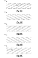
- FIG. 10A is a schematic illustration of an elevational view of a portion of the cable of FIG. 1 having an outer helix configuration defining an outer right regular lay;
- FIG. 10B is a schematic illustration of an elevational view of a portion of the cable of FIG. 1 having an outer helix configuration defining an outer left regular lay;
- FIG. 10C is a schematic illustration of an elevational view of a portion of the cable of FIG. 1 having an outer helix configuration defining an outer right lang lay;
- FIG. 10D is a schematic illustration of an elevational view of a portion of the cable of FIG. 1 having an outer helix configuration defining an outer left lang lay;
- FIG. 10E is a schematic illustration of an elevational view of a portion of the cable of FIG. 1 having an outer helix configuration defining an outer right alternate lay;
- FIG. 11 is a schematic illustration of an elevational view of a portion of the cable of FIG. 1 having an outer helix configuration defining a helix angle;
- FIG. 12 is a schematic illustration of a cross-sectional view of another embodiment of the cable of FIG. 1 taken along section lines 9 - 9 ;
- FIG. 13 is a schematic illustration of a cross-sectional view of yet another embodiment of the cable of FIG. 1 taken along section lines 9 - 9 .
- a cable protection system 10 is shown generally in FIGS. 1 and 2
- a method 12 of reducing an initial stress 58 ( FIG. 1 ) on a cable 14 is shown generally in FIG. 3
- the cable protection system 10 and method 12 may be useful for applications requiring protection of cables 14 from an overload condition.
- the cable 14 may require protection from a load 16 ( FIG. 1 ) generating a force (denoted generally by arrow 18 in FIG. 1 ) in excess of a yield strength of the cable 14 .
- loads 16 may overstress and overstretch the cable 14 , and thereby damage the cable 14 .
- loads 16 may fray, warp, bend, and/or break at least a portion of the cable 14 .
- the cable protection system 10 and method 12 may be useful for automotive applications requiring excellent cable strength and longevity. However, the cable protection system 10 and method 12 may also be useful for non-automotive applications including, but not limited to, marine, aviation, civil engineering, and recreation applications.
- the cable protection system 10 includes the cable 14 having a central longitudinal axis 40 and including a plurality of wires 22 ( FIG. 8 ) each twisted around the central longitudinal axis 40 . That is, the cable 14 generally includes a plurality of longitudinally engaged and cooperatively functioning wires 22 .
- the cable 14 may be used to lift the load 16 ( FIG. 1 ), and as such may have excellent tensile strength.
- the terminology “cable” encompasses other geometric forms such as, but not limited to, ropes, braids, bundles, and the like.
- FIGS. 8 and 9 show an exemplary cable 14 wherein the plurality of wires 22 are helically wound about a core 20 , so as to form a plurality of strands 24 .
- the core 20 may support the wires 22 and the strands 24 into a nominally circular cross-section, as best shown in FIG. 9 .
- the plurality of strands 24 may then be helically wound about another axial strand 24 that serves as the core 20 ( FIGS. 8 and 9 ). It is to be appreciated that the helical strands 24 may be the major load bearing elements of the cable 14 .
- the core 20 may lie along the central longitudinal axis 40 of the cable 14 .
- the core 20 may be formed of a suitably flexible and compressible material that, among other things, enables the cable 14 to achieve a minimum spooling radius and presents strain compatibility.
- the core 20 may be formed of rubber, foam, aluminum, copper, plastic, cotton, shape memory alloy in either the martensitic or austenitic phase, or combinations of these and other similar materials.
- the core 20 may further present a heating and/or cooling element (not shown) configured to actuate or dissipate heat from the strands 24 or wires 22 of the cable 14 .
- the core 20 may be formed of a thermally-conductive material and may be thermally coupled to a source (not shown), such as a thermoelectric element. Where Joule heating is to occur, the core 20 may be selected, in cooperation with a voltage range of the source, to provide a desired resistance that promotes power efficiency, and, for example, may comprise at least one Nichrome wire.
- the core 20 may present a flexible conduit that defines an internal space (not shown) that is fluidly coupled to a heated or cooling fluid (not shown).
- each of the plurality of wires 22 is formed from a shape memory alloy transitionable in response to an activation signal 26 ( FIG. 5 ) between a first temperature-dependent state 28 ( FIG. 4 ) wherein each of the plurality of wires 22 has a first temperature-dependent length 30 ( FIG. 4 ), and a second temperature-dependent state 32 ( FIG. 5 ) wherein each of the plurality of wires 22 has a second temperature-dependent length 34 ( FIG. 5 ) that is less than the first temperature-dependent length 30 .
- each of the plurality of wires 22 may shorten or constrict in length as the shape memory alloy transitions from the first temperature-dependent state 28 to the second temperature-dependent state 32 .
- shape memory alloy generally refers to a group of metallic materials that demonstrate the ability to return to some previously-defined shape or size when subjected to an appropriate thermal stimulus. Shape memory alloys are capable of undergoing phase transitions in which their yield strength, stiffness, dimension, and/or shape are altered as a function of temperature.
- yield strength refers to the stress at which a material exhibits a specified deviation from proportionality of stress and strain.
- shape memory alloys exist in a low symmetry monoclinic B19′ structure with twelve energetically equivalent lattice correspondence variants that can be pseudo-plastically deformed.
- shape memory alloys Upon exposure to some higher temperature, shape memory alloys will transform to an austenite or parent phase, i.e., the second temperature-dependent state 32 , which has a B2 (cubic) crystal structure. Transformation returns the shape memory alloy to its shape prior to the deformation. Materials that exhibit this shape memory effect only upon heating are referred to as having one-way shape memory. Those materials that also exhibit shape memory upon re-cooling are referred to as having two-way shape memory behavior.
- shape memory alloys may exist in several different temperature-dependent phases or states 28 , 32 .
- the most commonly utilized of these phases are the so-called martensite and austenite phases or states 28 , 32 discussed above.
- the martensite phase or first temperature-dependent state 28 ( FIG. 4 ) generally refers to the more deformable, lower temperature phase
- the austenite phase or second temperature-dependent state 32 ( FIG. 5 ) generally refers to the more rigid, higher temperature phase.
- the shape memory alloy is in the martensite phase or first temperature-dependent state 28 and is heated, it begins to change into the austenite phase or second temperature-dependent state 32 .
- the temperature at which this phenomenon starts is often referred to as austenite start temperature (A s ).
- the temperature at which this phenomenon is complete is called the austenite finish temperature (A f ).
- a suitable activation signal 26 for use with shape memory alloys is a thermal activation signal having a magnitude to cause transformations between the martensite and austenite phases, i.e., the first and second temperature-dependent states 28 , 32 , respectively.
- Shape memory alloys can exhibit a one-way shape memory effect, an intrinsic two-way effect, or an extrinsic two-way shape memory effect depending on the alloy composition and processing history.
- Annealed shape memory alloys typically only exhibit the one-way shape memory effect. Sufficient heating subsequent to low-temperature deformation of the shape memory alloy will induce the martensite-to-austenite type transition, and the alloy will recover the original, annealed shape. Hence, one-way shape memory effects are only observed upon heating. Active materials comprising shape memory alloy compositions that exhibit one-way memory effects do not automatically reform, and often require an external mechanical force to reset the device.
- active material refers to any material or composition that exhibits a reversible change in a fundamental (e.g., chemical or intrinsic physical) property, when exposed to or occluded from the activation signal 26 .
- Suitable active materials include, but are not limited to, shape memory materials (e.g., shape memory alloys), ferromagnetic shape memory alloys, and electro-active polymers, etc.). It is appreciated that these types of active materials have the ability to rapidly displace, or remember their original shape and/or elastic modulus, which can subsequently be recalled by applying an external stimulus. As such, deformation from the original shape is a temporary condition.
- Intrinsic and extrinsic two-way shape memory alloys are characterized by a shape transition both upon heating from the martensite phase or first temperature-dependent state 28 ( FIG. 4 ) to the austenite phase or second temperature-dependent state 32 ( FIG. 5 ), as well as an additional shape transition upon cooling from the austenite phase or second temperature-dependent state 32 back to the martensite phase or first temperature-dependent state 28 .
- Active materials that exhibit an intrinsic shape memory effect are fabricated from a shape memory alloy composition that will cause the shape memory alloy to automatically reform itself as a result of the above-noted phase transformations.
- Intrinsic two-way shape memory behavior must be induced in the shape memory alloy through processing.
- Such procedures include extreme deformation of the alloy while in the martensite phase or first temperature-dependent state 28 , heating-cooling under constraint or load, or surface modification such as laser annealing, polishing, or shot-peening.
- shape memory alloys that exhibit the extrinsic two-way shape memory effects are composite or multi-component materials that combine a shape memory alloy composition that exhibits a one-way effect with another element that provides a restoring force to reform an original shape.
- the temperature at which the shape memory alloy remembers its high temperature form when heated can be adjusted by slight changes in the composition of the alloy and through heat treatment. In nickel-titanium shape memory alloys, for instance, it can be changed from above about 100° C. to below about ⁇ 100° C.
- the shape recovery process occurs over a range of just a few degrees and the start or finish of the transformation can be controlled to within a degree or two depending on the desired application and alloy composition.
- the mechanical properties of the shape memory alloy vary greatly over the temperature range spanning their transformation, and typically provide the system with shape memory effects, superelastic effects, and high damping capacity.
- Suitable shape memory alloys include, without limitation, nickel-titanium based alloys, indium-titanium based alloys, nickel-aluminum based alloys, nickel-gallium based alloys, copper based alloys (e.g., copper-zinc alloys, copper-aluminum alloys, copper-gold, and copper-tin alloys), gold-cadmium based alloys, silver-cadmium based alloys, indium-cadmium based alloys, manganese-copper based alloys, iron-platinum based alloys, iron-platinum based alloys, iron-palladium based alloys, and the like.
- the alloys can be binary, ternary, or any higher order so long as the shape memory alloy composition exhibits a shape memory effect, e.g., change in shape orientation, damping capacity, and the like.
- shape memory alloys may exhibit a modulus increase of 2.5 times and a dimensional change, i.e., a recovery of pseudo-plastic deformation induced when in the martensitic phase or first temperature-dependent state 28 ( FIG. 4 ), of up to 8% depending on the amount of pre-strain when heated above their martensite-to-austenite phase transition temperature.
- thermally-induced shape memory alloy phase changes are one-way so that a biasing force return mechanism (such as a spring) would be required to return the shape memory alloy to its starting configuration once the applied field is removed. Joule heating can be used to make the entire system electronically controllable.
- Shape memory alloys Stress-induced phase changes in shape memory alloys, caused by loading and unloading of shape memory alloys (when at temperatures above A f ), are two-way by nature. That is to say, application of sufficient stress when a shape memory alloy is in its austenitic phase or second temperature-dependent state 32 ( FIG. 5 ) will cause the shape memory alloy to change to its lower modulus martensitic phase or first temperature-dependent state 28 ( FIG. 4 ) in which it can exhibit up to 8% of “superelastic” deformation. Removal of the applied stress will cause the shape memory alloy to switch back to its austenitic phase or second temperature-dependent state 32 , and in so doing, recover its starting shape and higher modulus.
- Ferromagnetic shape memory alloys are a sub-class of shape memory alloy. These materials behave like conventional shape memory alloys that have a stress- or thermally-induced phase transformation between martensite and austenite. Additionally, ferromagnetic shape memory alloys are ferromagnetic and have strong magnetocrystalline anisotropy, which permit an external magnetic field to influence the orientation/fraction of field-aligned martensitic variants. When the magnetic field is removed, the ferromagnetic shape memory alloy may exhibit complete two-way, partial two-way, or one-way shape memory. For partial two-way or one-way shape memory, an external stimulus, temperature, magnetic field or stress may permit the ferromagnetic shape memory alloy to return to its starting state. Perfect two-way shape memory may be used for proportional control with continuous power supplied. External magnetic fields are generally produced via soft-magnetic core electromagnets in automotive applications, though a pair of Helmholtz coils may also be used for fast response.
- the cable 14 may also include, in addition to the plurality of wires 22 , a plurality of lines 36 formed from a non-shape memory alloy material.
- the plurality of lines 36 may be included to provide increased structural integrity, act as a return spring, or otherwise tailor the performance of the cable 14 .
- structural integrity it is to be appreciated that the plurality of wires 22 and strands 24 generally support tensile loads in parallel, so as to provide redundancy.
- the diameters of the plurality of wires 22 may be congruent or variable, but are cooperatively configured to generate a required lifting force.
- the plurality of wires 22 may be preformed by plastic deformation into a helical reference configuration consistent with a desired geometry to avoid formation of burrs.
- the plurality of wires 22 may present non-helical permanent shapes, so that upon activation of the shape memory alloy, the cable 14 may exhibit linear and/or rotational displacement as the shape memory alloy transitions between the first temperature-dependent state 28 ( FIG. 4 ) and the second temperature-dependent state 32 ( FIG. 5 ), as set forth in more detail below.
- each wire 22 ( FIG. 8 ) in a strand 24 ( FIG. 8 ) may present congruent helices defining a helix angle 38 ( FIG. 11 ) and direction of lay.
- the present disclosure may encompass other geometric forms such as straight bundles, braids, woven ropes, etc.
- the helices of the wires 22 in a strand 24 versus that of the strands 24 in a given layer can be laid in an opposite sense (i.e., regular lay) or in the same sense (i.e., lang lay), which affects the helix angle 38 the wires 22 make with the central longitudinal axis 40 ( FIG. 8 ) of the cable 14 .
- the outer wire 22 /strand 24 helix configurations may present a right regular ( FIG. 10A ), left regular ( FIG. 10B ), right lang ( FIG. 10C ), left lang ( FIG. 10D ), or right alternate ( FIG. 10E ) lay.
- the helix angle 38 and lay may help determine the axial stiffness, stored elastic energy, bending/twisting compliance, exterior smoothness, abrasion resistance, and redundancy of the cable 14 .
- the helix angle 38 is inversely proportional to a yield strength of the cable 14 .
- the cable protection system 10 also includes a plurality of rails 42 , e.g., two rails 42 , translatable between a first position 44 ( FIG. 1 ) wherein each of the plurality of rails 42 is disposed adjacent to and in contact with the cable 14 , and a second position 46 ( FIG. 2 ) wherein each of the plurality of rails 42 is spaced apart from the cable 14 .
- a plurality of rails 42 e.g., two rails 42 , translatable between a first position 44 ( FIG. 1 ) wherein each of the plurality of rails 42 is disposed adjacent to and in contact with the cable 14 , and a second position 46 ( FIG. 2 ) wherein each of the plurality of rails 42 is spaced apart from the cable 14 .
- the cable 14 may have a fixed end 48 and a distal end 50 spaced opposite the fixed end 48 , and may further include a sheath 52 attached to the distal end 50 .
- the sheath 52 may include a constraining pin 54 extending therefrom. Therefore, when the plurality of rails 42 are disposed in the first position 44 , each of the plurality of rails 42 may prevent rotation of the constraining pin 54 and cable 14 about the central longitudinal axis 40 . That is, the constraining pin 54 and cable 14 may not rotate about the central longitudinal axis 40 when the plurality of rails 42 are disposed adjacent to and in contact with the cable 14 and sheath 52 .
- each of the plurality of rails 42 may allow rotation of the constraining pin 54 and cable 14 about the central longitudinal axis 40 of the cable 14 . That is, the constraining pin 54 and cable 14 may rotate about the central longitudinal axis 40 , e.g., in the direction of arrow 96 , when the plurality of rails are spaced apart from the cable 14 and sheath 52 .
- each of the plurality of wires 22 may be twisted around the central longitudinal axis 40 into a first twisted configuration 56 .
- the cable 14 may have a first stiffness (shown generally in FIG. 1 ) when the shape memory alloy has the first temperature-dependent state 28 ( FIG. 4 ).
- the first twisted configuration 56 may correspond to a condition wherein the cable 14 is subject to the initial stress 58 ( FIG. 1 ).
- each of the plurality of wires 22 may be slackened about the central longitudinal axis 40 into a second twisted configuration 60 when the shape memory alloy has the second temperature-dependent state 32 ( FIG. 5 ).
- the cable 14 may have a second stiffness (shown generally in FIG. 2 ) that is less than the first stiffness when the shape memory alloy has the second temperature-dependent state 32 . That is, each of the plurality of wires 22 may at least partially untwist about the central longitudinal axis 40 as the shape memory alloy transitions from the first temperature-dependent state 28 to the second temperature-dependent state 32 .
- each of the plurality of wires 22 may be at least partially untwistable with respect to the central longitudinal axis 40 such that the cable 14 is transitionable from a first length 64 ( FIG. 1 ) to a second length 66 ( FIG. 2 ) that is greater than the first length 64 as each of the plurality of wires 22 elongates from the second temperature-dependent length 34 ( FIG. 5 ).
- the method 12 includes stretching 68 ( FIG. 3 ) the cable 14 to the first length 64 in response to the force 18 generated by the load 16 to thereby define the initial stress 58 on the cable 14 .
- the cable 14 has the central longitudinal axis 40 , and includes the plurality of wires 22 each twisted around the central longitudinal axis 40 and formed from the shape memory alloy, as set forth above. More specifically, the cable 14 may be attached to the load 16 and may begin to lift, translate, or move the load 16 in a direction denoted generally by arrow 70 .
- the force 18 generated by the load 16 stretches the cable 14 so that the cable 14 may snug down upon itself, and the cable 14 may lengthen to the first length 64 . That is, the plurality of wires 22 may snug down upon the central longitudinal axis 40 in the direction of arrow 72 ( FIG. 1 ), and the cable 14 may stretch such that the cable 14 has the first stiffness and is subjected to the initial stress 58 .
- the first length 64 and initial stress 58 may correspond to a limit of the cable 14 such that the cable 14 is not overloaded, overstressed, or overstretched. That is, the first length 64 and initial stress 58 may correspond to a condition wherein the cable operates efficiently to begin to lift the load 16 and, for example, does not fray, warp, bend, and/or break.
- the method 12 also includes activating 74 the shape memory alloy by exposing the shape memory alloy to the activation signal 26 ( FIG. 2 ) such that the shape memory alloy transitions from the first temperature-dependent state 28 ( FIG. 4 ) to the second temperature-dependent state 32 ( FIG. 5 ).
- activating 74 may include exposing the shape memory alloy to heat, as set forth above, so that the shape memory alloy transitions from the first temperature-dependent state 28 wherein each of the plurality of wires 22 has the first temperature-dependent length 30 ( FIG. 4 ), to the second temperature-dependent state 32 wherein each of the plurality of wires 22 has the second temperature-dependent length 34 ( FIG. 5 ).
- the method 12 may also include, prior to activating 74 ( FIG. 3 ), retaining 76 the cable 14 in the first twisted configuration 56 .
- retaining 76 may include constraining the cable 14 between the plurality of rails 42 disposed adjacent to the cable 14 .
- retaining 76 may include constraining the constraining pin 54 between the plurality of rails 42 disposed adjacent to the cable 14 so that the cable 14 cannot rotate about the central longitudinal axis 40 .
- the method 12 may include, concurrent to activating 74 , modifying 78 the first stiffness (shown generally in FIG. 1 ) to the second stiffness (shown generally in FIG. 2 ) that is less than the first stiffness. That is, modifying 78 may include decreasing the first stiffness of the cable 14 .
- concurrently activating 74 and modifying 78 may include partially untwisting the plurality of wires 22 with respect to the central longitudinal axis 40 of the cable 14 .
- the method 12 further includes, concurrent to activating 74 ( FIG. 3 ), elongating 80 ( FIG. 3 ) the cable 14 to the second length 66 that is greater than the first length 64 ( FIG. 1 ) in response to the force 18 to define a second stress 62 on the cable 14 that is less than the initial stress 58 ( FIG. 1 ) and thereby reduce the initial stress 58 on the cable. That is, elongating 80 may protect the cable 14 from overstretching due to overstress of the cable 14 , i.e., stressing the cable 14 beyond the initial stress 58 . More specifically, elongating 80 may include lengthening each of the plurality of wires 22 from the second temperature-dependent length 34 ( FIG. 5 ).
- elongating 80 may include translating the plurality of rails 42 away from the cable 14 to thereby unconstrain the cable 14 and reduce the initial stress 58 ( FIG. 1 ) to the second stress 62 . That is, translating the plurality of rails 42 away from the cable 14 may allow the cable 14 to rotate about the central longitudinal axis 40 , e.g., in the direction of arrow 96 . Therefore, upon concurrent activating 74 ( FIG. 3 ) and elongating 80 ( FIG. 3 ), the plurality of wires 22 may at least partially untwist from the central longitudinal axis 40 .
- the plurality of wires 22 may be slackened about the central longitudinal axis 40 into the second twisted configuration 60 , e.g., such that the cable 14 has the second stiffness when the shape memory alloy has the second temperature-dependent state 32 ( FIG. 5 ).
- the second twisted configuration 60 may correspond to a condition wherein the cable 14 is subject to the second stress 62 ( FIG. 2 ).
- the shape memory alloy may attempt to revert or transition from the first temperature-dependent state 28 ( FIG. 4 ) to the second temperature-dependent state 32 ( FIG. 5 ). Stated differently, each of the plurality of wires 22 may attempt to shorten from the first temperature-dependent length 30 ( FIG. 4 ) to the second temperature-dependent length 34 ( FIG. 5 ) as a temperature of the shape memory alloy increases.
- the method 12 may include allowing the cable 14 to at least partially untwist to thereby provide each of the plurality of wires 22 space or room to reconfigure, i.e., lengthen and elongate, along the central longitudinal axis 40 ( FIG. 2 ).
- Such reconfiguration from the first twisted configuration 56 ( FIG. 6 ) to the second twisted configuration 60 ( FIG. 6 ) may reduce the strain of each wire 22 and thereby decrease the initial stress 58 ( FIG. 1 ) and first stiffness of the cable 14 to the second stress 62 ( FIG. 7 ) and second stiffness, respectively.
- concurrently activating 74 and elongating 80 may include partially untwisting the plurality of wires 22 with respect to the central longitudinal axis 40 from the first twisted configuration 56 to the second twisted configuration 60 . That is, concurrently activating 74 ( FIG. 3 ) the shape memory alloy and elongating 80 ( FIG. 3 ) the cable 14 may alleviate or reduce the initial stress 58 on the cable 14 and allow the cable 14 to continue to lift, translate, or move the load 16 without overstressing and/or overstretching. As such, concurrent activation of the shape memory alloy and elongation of the cable 14 to thereby reduce the initial stress 58 to the second stress 62 may prevent damage to and overloading of the cable 14 , and may modify the first stiffness to the second stiffness.
- the cable 14 may further include an inter-wire element 82 longitudinally engaged with and disposed adjacent to the plurality of wires 22 .
- the inter-wire element 82 may extend along the central longitudinal axis 40 ( FIG. 1 ) along an entirety of the cable 14 , or may be disposed along select longitudinal portions (not shown) of the cable 14 .
- the inter-wire element 82 is operable to modify interaction between the plurality of wires 22 .
- the inter-wire element 82 may be a wire surface condition (e.g., texturing), one or more spacers 84 ( FIG. 13 ), a lubricant 86 ( FIG. 12 ), a cover 88 ( FIG. 13 ), or a wire coating, e.g., carbon nanotubes as fins (not shown), that promotes actuation, facilitates performance, protects the interstitial cable components, or otherwise extends an operating life of the cable 14 , as set forth in more detail below.
- a wire surface condition e.g., texturing
- spacers 84 FIG. 13
- a lubricant 86 FIG. 12
- cover 88 FIG. 13
- a wire coating e.g., carbon nanotubes as fins (not shown)
- the method 12 includes, concurrent to activating 74 ( FIG. 3 ), contacting 90 ( FIG. 3 ) at least one of the plurality of wires 22 and the inter-wire element 82 . That is, concurrently activating 74 and contacting 90 may include partially untwisting the plurality of wires 22 with respect to the central longitudinal axis 40 ( FIG. 2 ) of the cable 14 , and may thereby modify 78 ( FIG. 3 ) the first stiffness (shown generally in FIG. 1 ) to the second stiffness (shown generally in FIG. 2 ) that is less than the first stiffness, and consequently reduce the initial stress 58 ( FIG. 1 ) to the second stress 62 ( FIG. 2 ).
- the inter-wire element 82 may include the one or more spacers 84 and may be attached to the core 20 and/or the plurality of wires 22 to aid or hinder heating or cooling by modifying or preventing wire interaction.
- the spacer 84 may be formed from a resilient material, such as a rubber or an elastomer. Further, a thickness and/or stiffness of the spacer 84 may be selected to prevent the cable 14 from exceeding a predetermined strain level.
- the one or more spacers 84 may be disposed between adjacent ones of the plurality of wires 22 , and contacting 90 ( FIG. 3 ) may include spreading adjacent ones of the plurality of wires 22 apart from one another.
- contacting 90 may include resisting compression of each of the plurality of wires 22 in a direction (denoted generally by arrow 72 in FIG. 13 ) perpendicular to the central longitudinal axis 40 ( FIG. 1 ) of the cable 14 . That is, as the shape memory alloy transitions from the first temperature-dependent state 28 ( FIG. 4 ) to the second temperature-dependent state 32 ( FIG. 5 ), each of the plurality of wires 22 may attempt to shorten from the first temperature-dependent length 30 ( FIG. 4 ) to the second temperature-dependent length 34 ( FIG. 5 ) and thereby begin to compress against the central longitudinal axis 40 .
- the one or more spacers 84 may prevent compression of the plurality of wires 22 against the core 20 or central longitudinal axis 40 and may instead allow the plurality of wires 22 to remain spaced apart from one another so as to allow at least a partial untwisting of the cable 14 to the second twisted configuration 60 ( FIG. 2 ). Stated differently, as the plurality of wires 22 squeeze down upon the spacer 84 , the spacer 84 may resist the compression and spread the plurality of wires 22 apart from one another to reduce or relieve the initial stress 58 on the cable 14 .
- contacting 90 may include reducing a coefficient of friction between adjacent ones of the plurality of wires 22 to thereby reduce the initial stress 58 ( FIG. 1 ) to the second stress 62 ( FIG. 2 ).
- the inter-wire element 82 may include the lubricant 86 disposed between adjacent ones of the plurality of wires 22 .
- the lubricant 86 may be, for example, petroleum jelly that is operable to reduce the coefficient of friction between adjacent ones of the plurality of wires 22 .
- the lubricant 86 may be thermally- and/or electrically-insulating. Conversely, to enable more uniform actuation from a single strand 24 or wire 22 , the lubricant 86 may be thermally- and/or electrically-conducting.
- contacting 90 may include longitudinally sliding adjacent ones of the plurality of wires 22 with respect to one another to thereby partially untwist the plurality of wires 22 with respect to the central longitudinal axis 40 ( FIG. 1 ). That is, the lubricant 86 ( FIG. 12 ) may reduce the coefficient of friction between individual ones of the plurality of wires 22 . As the force 18 ( FIG. 1 ) generated by the load 16 ( FIG. 1 ) is applied to the cable 14 , the lubricant 86 may allow longitudinal sliding of the plurality of wires 22 with respect to one another. As such, the plurality of wires 22 may reconfigure from the first twisted configuration 56 ( FIG.
- the lubricant 86 may help each of the plurality of wires 22 align longitudinally along the central longitudinal axis 40 .
- the plurality of wires 22 may be coated, covered, or treated, so as to present a desired surface condition.
- the cover 88 may be applied to each of the plurality of wires 22 to modify fatigue/thermo-mechanical interface properties of each wire 22 .
- the cover 88 may be configured to modify the coefficient of friction between adjacent ones of the plurality of wires 22 .
- the cover 88 e.g., TeflonTM 66 , may be used to coat individual strands 24 or wires 22 .
- the response of the cable 14 may be tailored by modifying the frictional contribution from strand 24 /wire 22 to strand 24 /wire 22 .
- the coating or cover 88 may be used to modify emissivity or heat transfer properties of each of the plurality of wires 22 .
- a light- or electromagnetic field-sensitive coating may be used in conjunction with a suitable, e.g., fiber optic, core 20 , such that the passage of light or other medium causes the coating to generate heat energy.
- the inter-wire element 82 may change phase in response to the activation signal 26 ( FIG. 2 ) between a first phase 92 having a first flexibility and a second phase 94 having a second flexibility that is greater than the first flexibility. That is, the inter-wire element 82 may become more flexible upon exposure to the activation signal 26 .
- the inter-wire element 82 may be formed from a wax that may change from a solid, i.e., the first phase 92 , to a liquid, i.e., the second phase 94 , upon exposure to the activation signal 26 , e.g., heat.
- the inter-wire element 82 may be an active material, such as a shape memory polymer, that may decrease in flexibility from the first flexibility to the second flexibility by from about 100% to about 400%.
- concurrently activating 74 ( FIG. 3 ) and contacting 90 ( FIG. 3 ) may include partially untwisting the plurality of wires 22 with respect to the central longitudinal axis 40 ( FIG. 1 ) of the cable 14 . That is, the plurality of wires 22 may reconfigure from the first twisted configuration 56 ( FIG. 1 ) to the second twisted configuration 60 ( FIG. 2 ) and thereby lengthen the cable 14 to at least the second length 66 ( FIG. 2 ) to reduce the initial stress 58 on the cable 14 to the second stress 62 .
- each of the plurality of wires 22 begins to transition from the first temperature-dependent state 28 ( FIG. 4 ) to the second temperature-dependent state 32 ( FIG. 5 ) and stress and strain on the cable 14 begins to increase
- concurrently activating 74 ( FIG. 3 ) the shape memory alloy and elongating 80 ( FIG. 3 ) the cable 14 to the second length 66 ( FIG. 2 ) allows the cable 14 to transition from the first twisted configuration 56 ( FIGS. 1 and 6 ) to the second twisted configuration 60 ( FIGS. 2 and 7 ), and allows the initial stress 58 ( FIGS. 1 and 6 ) and first stiffness to relax to the second stress 62 ( FIGS. 2 and 7 ) and second stiffness, respectively.
- the cable 14 may be operable to lift the load 16 . That is, as the cable 14 begins to lift the load 16 so that the cable 14 is stretched along the central longitudinal axis 40 , the shape memory alloy is activated, which may increase the temperature of the shape memory alloy and cause the shape memory alloy to attempt to revert to the second temperature-dependent state 32 ( FIG. 5 ). That is, upon activation, the shape memory alloy may attempt to shorten from the first temperature-dependent length 30 ( FIG. 4 ) to the second temperature-dependent length 34 ( FIG. 5 ). Without the cable protection system 10 and method 12 , the plurality of wires 22 may be increasingly constrained against one another as the cable 14 stretches in response to the load 16 .
- Such conditions may increase stress and strain on the cable 14 and cause the cable 14 and/or any one of the plurality of wires 22 to fail to perform, e.g., to fray, warp, bend, and/or break. That is, such conditions may overload, overstress, and/or overstretch the cable 14 .
- the cable protection system 10 and method 12 reduce the initial stress 58 ( FIG. 1 ) and minimize strain on the cable 14 , and therefore protect the cable 14 from damage due to overloading, overstressing, and/or overstretching.
- the cable protection system 10 and method 12 may reduce the initial stress 58 to the second stress 62 and may relieve strain on the cable 14 by allowing each of the plurality of wires 22 to assume an elongated, longer, and straighter path along the central longitudinal axis 40 by at least partially untwisting the cable 14 from the first twisted configuration 56 to the second twisted configuration 60 . That is, the cable protection system 10 and method 12 may align each of the plurality of wires 22 substantially parallel to the central longitudinal axis 40 of the cable 14 as the cable 14 elongates. As such, the cable protection system 10 and method 12 allow the cable 14 to physically reconfigure to a strain- and stress-reducing arrangement to thereby reduce the initial stress 58 on each of the plurality of wires 22 .
Abstract
Description
Claims (20)
Priority Applications (1)
| Application Number | Priority Date | Filing Date | Title |
|---|---|---|---|
| US13/587,383 US8881521B2 (en) | 2008-03-07 | 2012-08-16 | Cable protection system and method of reducing an initial stress on a cable |
Applications Claiming Priority (4)
| Application Number | Priority Date | Filing Date | Title |
|---|---|---|---|
| US3488408P | 2008-03-07 | 2008-03-07 | |
| US3491308P | 2008-03-07 | 2008-03-07 | |
| US12/397,482 US8272214B2 (en) | 2008-03-07 | 2009-03-04 | Shape memory alloy cables |
| US13/587,383 US8881521B2 (en) | 2008-03-07 | 2012-08-16 | Cable protection system and method of reducing an initial stress on a cable |
Related Parent Applications (1)
| Application Number | Title | Priority Date | Filing Date |
|---|---|---|---|
| US12/397,482 Continuation-In-Part US8272214B2 (en) | 2008-03-07 | 2009-03-04 | Shape memory alloy cables |
Publications (2)
| Publication Number | Publication Date |
|---|---|
| US20120324858A1 US20120324858A1 (en) | 2012-12-27 |
| US8881521B2 true US8881521B2 (en) | 2014-11-11 |
Family
ID=47360503
Family Applications (1)
| Application Number | Title | Priority Date | Filing Date |
|---|---|---|---|
| US13/587,383 Active 2029-07-31 US8881521B2 (en) | 2008-03-07 | 2012-08-16 | Cable protection system and method of reducing an initial stress on a cable |
Country Status (1)
| Country | Link |
|---|---|
| US (1) | US8881521B2 (en) |
Cited By (9)
| Publication number | Priority date | Publication date | Assignee | Title |
|---|---|---|---|---|
| US20150152942A1 (en) * | 2013-12-02 | 2015-06-04 | Schlage Lock Company Llc | Multi-pass crimp collar for a looped cable |
| US20150152669A1 (en) * | 2013-12-02 | 2015-06-04 | Schlage Lock Company Llc | Twistable Security Cable |
| US20150323424A1 (en) * | 2014-05-06 | 2015-11-12 | GM Global Technology Operations LLC | Test method |
| US20160017870A1 (en) * | 2013-03-04 | 2016-01-21 | Syracuse University | Reversible Shape Memory Polymers Exhibiting Ambient Actuation Triggering |
| US20180100269A1 (en) * | 2016-04-13 | 2018-04-12 | Jiangsu Fasten Steel Cable Co., Ltd. | Method for fabricating steel wire cable comprising zinc- aluminium alloy plating |
| US10597917B2 (en) | 2017-10-09 | 2020-03-24 | GM Global Technology Operations LLC | Stretchable adjustable-stiffness assemblies |
| US11400766B2 (en) * | 2017-11-27 | 2022-08-02 | Jiangsu Xingda Steel Tyre Cord Co., Ltd. | Cable bead and tire |
| US11753125B2 (en) | 2020-08-24 | 2023-09-12 | Mark A. Gummin | Shape memory alloy actuator for inflation device |
| US11840319B2 (en) | 2020-12-09 | 2023-12-12 | Brian Joseph Stasey | Actuator for inflation device |
Families Citing this family (7)
| Publication number | Priority date | Publication date | Assignee | Title |
|---|---|---|---|---|
| ITMI20121545A1 (en) * | 2012-09-18 | 2014-03-19 | Copperweld Bimetallics Llc | SUPPORTING ROPE FOR CONTACT WIRES OF RAILWAY ELECTRIC LINES |
| GB2533159A (en) | 2014-12-12 | 2016-06-15 | Exergyn Ltd | Wire element arrangement in an energy recovery device |
| GB2533163A (en) * | 2014-12-12 | 2016-06-15 | Exergyn Ltd | Protective element for use in an energy recovery device |
| CH711567A2 (en) * | 2015-09-24 | 2017-03-31 | Seilfabrik Ullmann Ag | Shock absorber body and game device with a shock absorber body. |
| JP2018078007A (en) * | 2016-11-09 | 2018-05-17 | 矢崎総業株式会社 | Aluminum twisted-wire and wire harness |
| CN110424264A (en) * | 2019-08-12 | 2019-11-08 | 广东迈诺工业技术有限公司 | High tough, permanent seal cooling bridge cable Zn-Al Alloy Coated Steel Wire |
| KR102520595B1 (en) * | 2021-04-26 | 2023-04-10 | 홍익대학교 산학협력단 | Cable using cold drawn shape memory alloy wires and its manufacturing process |
Citations (2)
| Publication number | Priority date | Publication date | Assignee | Title |
|---|---|---|---|---|
| US2758491A (en) * | 1951-12-06 | 1956-08-14 | Aircraft Marine Prod Inc | Crimping dies for electrical connectors |
| US20050150223A1 (en) * | 2000-03-03 | 2005-07-14 | United Technologies Corporation | Shape memory alloy bundles and actuators |
-
2012
- 2012-08-16 US US13/587,383 patent/US8881521B2/en active Active
Patent Citations (2)
| Publication number | Priority date | Publication date | Assignee | Title |
|---|---|---|---|---|
| US2758491A (en) * | 1951-12-06 | 1956-08-14 | Aircraft Marine Prod Inc | Crimping dies for electrical connectors |
| US20050150223A1 (en) * | 2000-03-03 | 2005-07-14 | United Technologies Corporation | Shape memory alloy bundles and actuators |
Cited By (14)
| Publication number | Priority date | Publication date | Assignee | Title |
|---|---|---|---|---|
| US20160017870A1 (en) * | 2013-03-04 | 2016-01-21 | Syracuse University | Reversible Shape Memory Polymers Exhibiting Ambient Actuation Triggering |
| US9453501B2 (en) * | 2013-03-04 | 2016-09-27 | Patrick T. Mather | Reversible shape memory polymers exhibiting ambient actuation triggering |
| US10221523B2 (en) * | 2013-12-02 | 2019-03-05 | Schlage Lock Company Llc | Multi-pass crimp collar for a looped cable |
| US20150152669A1 (en) * | 2013-12-02 | 2015-06-04 | Schlage Lock Company Llc | Twistable Security Cable |
| US9470021B2 (en) * | 2013-12-02 | 2016-10-18 | Schlage Lock Company Llc | Twistable security cable |
| US9828724B2 (en) * | 2013-12-02 | 2017-11-28 | Schlage Lock Company Llc | Multi-pass crimp collar for a looped cable |
| US20150152942A1 (en) * | 2013-12-02 | 2015-06-04 | Schlage Lock Company Llc | Multi-pass crimp collar for a looped cable |
| US20150323424A1 (en) * | 2014-05-06 | 2015-11-12 | GM Global Technology Operations LLC | Test method |
| US9588020B2 (en) * | 2014-05-06 | 2017-03-07 | GM Global Technology Operations LLC | Test method |
| US20180100269A1 (en) * | 2016-04-13 | 2018-04-12 | Jiangsu Fasten Steel Cable Co., Ltd. | Method for fabricating steel wire cable comprising zinc- aluminium alloy plating |
| US10597917B2 (en) | 2017-10-09 | 2020-03-24 | GM Global Technology Operations LLC | Stretchable adjustable-stiffness assemblies |
| US11400766B2 (en) * | 2017-11-27 | 2022-08-02 | Jiangsu Xingda Steel Tyre Cord Co., Ltd. | Cable bead and tire |
| US11753125B2 (en) | 2020-08-24 | 2023-09-12 | Mark A. Gummin | Shape memory alloy actuator for inflation device |
| US11840319B2 (en) | 2020-12-09 | 2023-12-12 | Brian Joseph Stasey | Actuator for inflation device |
Also Published As
| Publication number | Publication date |
|---|---|
| US20120324858A1 (en) | 2012-12-27 |
Similar Documents
| Publication | Publication Date | Title |
|---|---|---|
| US8881521B2 (en) | Cable protection system and method of reducing an initial stress on a cable | |
| US8272214B2 (en) | Shape memory alloy cables | |
| US8741076B2 (en) | Apparatus and method of controlling phase transformation temperature of a shape memory alloy | |
| US8567188B2 (en) | Accelerating cooling in active material actuators using heat sinks | |
| ES2380588T3 (en) | Supporting and dragging means of flat belt type with traction supports | |
| US8388773B2 (en) | Apparatus for and method of conditioning shape memory alloy wire | |
| US20200345475A1 (en) | Carbon nanotube sheet wrapping muscles | |
| US20120174573A1 (en) | Multi-segmented active material actuator | |
| KR102361097B1 (en) | Actuator and its manufacturing method | |
| BR0214379B1 (en) | cable and window lift system using such cable. | |
| EP1745232A1 (en) | Flat high-tensile wire as hose reinforcement | |
| US8857273B2 (en) | Mechanical overload protection utilizing superelastic shape memory alloy actuation | |
| JP6440847B2 (en) | Wire for elastic member and elastic member | |
| CN103129829B (en) | Fixing assembly | |
| EP0909665B1 (en) | Shape memory cords for reinforcing elastomeric articles, particulary for pneumatic tyres, and pneumatic tyre using said cords | |
| CN108350702B (en) | Gas-supporting string structure with shape memory wire rope | |
| CN209703305U (en) | Traction cable based on marmem | |
| JP2007332497A (en) | Shock-absorbing rope | |
| Chattopadhyay | Textile rope—a review | |
| ES2647274T3 (en) | Suspension and traction and lift system comprising at least one pulley and one suspension and traction element with at least one shape memory alloy cable | |
| JP5257986B2 (en) | Torsional motion converter | |
| EP2773810B1 (en) | Composite wire with protective external metallic mantle and internal fibre | |
| JP7370994B2 (en) | Overhead electrical cable and method of manufacturing the overhead electrical cable | |
| Gnanavel et al. | Effect of Interfacial Contact Forces and Lay Ratio in Cardiac Lead Outer Insulation due to Internal Cable Motion | |
| JPS61244938A (en) | Tensile member for power transmission belt |
Legal Events
| Date | Code | Title | Description |
|---|---|---|---|
| AS | Assignment |
Owner name: GM GLOBAL TECHNOLOGY OPERATIONS LLC, MICHIGAN Free format text: ASSIGNMENT OF ASSIGNORS INTEREST;ASSIGNORS:BROWNE, ALAN L.;ALEXANDER, PAUL W.;JOHNSON, NANCY L.;REEL/FRAME:028891/0045 Effective date: 20120822 |
|
| AS | Assignment |
Owner name: WILMINGTON TRUST COMPANY, DELAWARE Free format text: SECURITY AGREEMENT;ASSIGNOR:GM GLOBAL TECHNOLOGY OPERATIONS LLC;REEL/FRAME:030694/0591 Effective date: 20101027 |
|
| FEPP | Fee payment procedure |
Free format text: PAYOR NUMBER ASSIGNED (ORIGINAL EVENT CODE: ASPN); ENTITY STATUS OF PATENT OWNER: LARGE ENTITY |
|
| STCF | Information on status: patent grant |
Free format text: PATENTED CASE |
|
| AS | Assignment |
Owner name: GM GLOBAL TECHNOLOGY OPERATIONS LLC, MICHIGAN Free format text: RELEASE BY SECURED PARTY;ASSIGNOR:WILMINGTON TRUST COMPANY;REEL/FRAME:034192/0299 Effective date: 20141017 |
|
| MAFP | Maintenance fee payment |
Free format text: PAYMENT OF MAINTENANCE FEE, 4TH YEAR, LARGE ENTITY (ORIGINAL EVENT CODE: M1551) Year of fee payment: 4 |
|
| MAFP | Maintenance fee payment |
Free format text: PAYMENT OF MAINTENANCE FEE, 8TH YEAR, LARGE ENTITY (ORIGINAL EVENT CODE: M1552); ENTITY STATUS OF PATENT OWNER: LARGE ENTITY Year of fee payment: 8 |