US8666955B2 - Data management method and data management system - Google Patents
Data management method and data management system Download PDFInfo
- Publication number
- US8666955B2 US8666955B2 US13/132,056 US201113132056A US8666955B2 US 8666955 B2 US8666955 B2 US 8666955B2 US 201113132056 A US201113132056 A US 201113132056A US 8666955 B2 US8666955 B2 US 8666955B2
- Authority
- US
- United States
- Prior art keywords
- data
- data block
- chunks
- chunk
- hash value
- Prior art date
- Legal status (The legal status is an assumption and is not a legal conclusion. Google has not performed a legal analysis and makes no representation as to the accuracy of the status listed.)
- Expired - Fee Related, expires
Links
Images


Classifications
-
- G—PHYSICS
- G06—COMPUTING; CALCULATING OR COUNTING
- G06F—ELECTRIC DIGITAL DATA PROCESSING
- G06F16/00—Information retrieval; Database structures therefor; File system structures therefor
- G06F16/10—File systems; File servers
- G06F16/17—Details of further file system functions
- G06F16/174—Redundancy elimination performed by the file system
- G06F16/1748—De-duplication implemented within the file system, e.g. based on file segments
- G06F16/1752—De-duplication implemented within the file system, e.g. based on file segments based on file chunks
-
- G—PHYSICS
- G06—COMPUTING; CALCULATING OR COUNTING
- G06F—ELECTRIC DIGITAL DATA PROCESSING
- G06F3/00—Input arrangements for transferring data to be processed into a form capable of being handled by the computer; Output arrangements for transferring data from processing unit to output unit, e.g. interface arrangements
- G06F3/06—Digital input from, or digital output to, record carriers, e.g. RAID, emulated record carriers or networked record carriers
- G06F3/0601—Interfaces specially adapted for storage systems
- G06F3/0602—Interfaces specially adapted for storage systems specifically adapted to achieve a particular effect
- G06F3/0626—Reducing size or complexity of storage systems
-
- G—PHYSICS
- G06—COMPUTING; CALCULATING OR COUNTING
- G06F—ELECTRIC DIGITAL DATA PROCESSING
- G06F3/00—Input arrangements for transferring data to be processed into a form capable of being handled by the computer; Output arrangements for transferring data from processing unit to output unit, e.g. interface arrangements
- G06F3/06—Digital input from, or digital output to, record carriers, e.g. RAID, emulated record carriers or networked record carriers
- G06F3/0601—Interfaces specially adapted for storage systems
- G06F3/0628—Interfaces specially adapted for storage systems making use of a particular technique
- G06F3/0638—Organizing or formatting or addressing of data
- G06F3/0644—Management of space entities, e.g. partitions, extents, pools
-
- G—PHYSICS
- G06—COMPUTING; CALCULATING OR COUNTING
- G06F—ELECTRIC DIGITAL DATA PROCESSING
- G06F3/00—Input arrangements for transferring data to be processed into a form capable of being handled by the computer; Output arrangements for transferring data from processing unit to output unit, e.g. interface arrangements
- G06F3/06—Digital input from, or digital output to, record carriers, e.g. RAID, emulated record carriers or networked record carriers
- G06F2003/0697—Digital input from, or digital output to, record carriers, e.g. RAID, emulated record carriers or networked record carriers device management, e.g. handlers, drivers, I/O schedulers
-
- G—PHYSICS
- G06—COMPUTING; CALCULATING OR COUNTING
- G06F—ELECTRIC DIGITAL DATA PROCESSING
- G06F3/00—Input arrangements for transferring data to be processed into a form capable of being handled by the computer; Output arrangements for transferring data from processing unit to output unit, e.g. interface arrangements
- G06F3/06—Digital input from, or digital output to, record carriers, e.g. RAID, emulated record carriers or networked record carriers
- G06F3/0601—Interfaces specially adapted for storage systems
- G06F3/0602—Interfaces specially adapted for storage systems specifically adapted to achieve a particular effect
- G06F3/0608—Saving storage space on storage systems
-
- G—PHYSICS
- G06—COMPUTING; CALCULATING OR COUNTING
- G06F—ELECTRIC DIGITAL DATA PROCESSING
- G06F3/00—Input arrangements for transferring data to be processed into a form capable of being handled by the computer; Output arrangements for transferring data from processing unit to output unit, e.g. interface arrangements
- G06F3/06—Digital input from, or digital output to, record carriers, e.g. RAID, emulated record carriers or networked record carriers
- G06F3/0601—Interfaces specially adapted for storage systems
- G06F3/0628—Interfaces specially adapted for storage systems making use of a particular technique
- G06F3/0638—Organizing or formatting or addressing of data
- G06F3/064—Management of blocks
- G06F3/0641—De-duplication techniques
-
- G—PHYSICS
- G06—COMPUTING; CALCULATING OR COUNTING
- G06F—ELECTRIC DIGITAL DATA PROCESSING
- G06F3/00—Input arrangements for transferring data to be processed into a form capable of being handled by the computer; Output arrangements for transferring data from processing unit to output unit, e.g. interface arrangements
- G06F3/06—Digital input from, or digital output to, record carriers, e.g. RAID, emulated record carriers or networked record carriers
- G06F3/0601—Interfaces specially adapted for storage systems
- G06F3/0668—Interfaces specially adapted for storage systems adopting a particular infrastructure
- G06F3/067—Distributed or networked storage systems, e.g. storage area networks [SAN], network attached storage [NAS]
Definitions
- the present invention relates to a data management method and a data management system.
- Patent Literature 1 detects duplicate data by partitioning a file into variable lengths and computing a hash value for each partitioned piece of data
- a hash value is computed for each prescribed size from the start of a file, and a determination is made as to whether or not this hash value matches with a predetermined constant value.
- the file is partitioned at this part.
- an object of the present invention is to provide a data management method and a data management system that make it possible to partition and manage data in a relatively appropriate size.
- Another object of the present invention is to provide a data management method and a data management system that are able to manage data by partitioning the data into a size that approximates a prescribed size and efficiently eliminating duplicate data.
- a data management method is a data management method for partitioning and managing data blocks in variable lengths, including the steps of: (a1) computing a first hash value for each piece of data within a computation area for computing a hash value based on data within the computation area and a prescribed first hash function while sliding the computation area a prescribed amount at a time with respect to a prescribed range from a prescribed start location of the data block to a prescribed size; (a2) extracting, from among the hash values obtained within the prescribed range, a first hash value that is equivalent to a characteristic value, which is determined relatively based on a prescribed criterion; (a3) acquiring a first chunk of data by partitioning the data block at a location corresponding to the first hash value that is equivalent to the characteristic value; and (a4) repeatedly executing the a1, a2, and a3 with respect to the partitioned data block, for partitioning and managing the entire original data block as the multiple first chunks of data.
- the characteristic value may be either a minimum value or a maximum value among the first hash values obtained within the prescribed range.
- the first chunk of data may be created by partitioning the data block at a location corresponding to the first hash value that matches the theoretical limiting value.
- the prescribed start location may be configured as a value obtained by adding a prescribed lower limit to a start location of the data block.
- the entire data block may be regarded as the first chunk of data.
- the present invention may also be understood as a program for managing data.
- This computer program can be distributed via either a communication media or a recording medium.
- FIG. 1 is a schematic diagram showing an overview of the entire embodiment of the application.
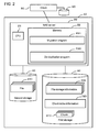
- FIG. 2 is a block diagram of a data management system.
- FIG. 3 is an example of the configuration of file storage information used for restoring a file from a chunk of data.
- FIG. 4 is an example of the configuration of index information for managing the chunk of data.
- FIG. 5 is a flowchart showing the overall flow of processing.
- FIG. 6 is a diagram schematically showing how file data as a data block is partitioned based on hash values.
- FIG. 7 is a schematic diagram showing another example of a window configuration location.
- FIG. 8 is a flowchart showing the processing for partitioning a file.
- FIG. 9 is a flowchart showing the processing for detecting and eliminating duplicate data.
- FIG. 10 is a flowchart related to a second example showing the processing for partitioning a file.
- FIG. 11 is a block diagram showing an entire data management system related to a third example.
- FIG. 12 is a flowchart showing the overall flow of processing.
- One or more first hash values having the smallest value (minimum value) and one or more second hash values having the largest value (maximum value) are included in a group of multiple first hash values. In a case where either multiples of either the minimum value or the maximum value exist, for example, whichever one is detected first can be used.
- FIG. 1 shows an overview of the entire embodiment of this specification.
- a data partitioning process S 1 a duplicate detection process S 2 and a data management process S 3 are shown in FIG. 1 .
- the data partitioning process S 1 is for partitioning file data.
- the duplicate detection process S 2 is for detecting duplicate data in the partitioned file data.
- the data management process S 3 is for partitioning and managing the file data.
- the data partitioning process S 1 will be explained.
- the data partitioning process S 1 for example, comprises a start location determination process S 10 , a first hash value computation process S 11 , a window sliding process S 12 , a characteristic value detection process S 13 , and a partition location determination process S 14 .
- the start location determination process S 10 determines a location HS from which to start a process for computing a first hash value.
- the window W depicted using the dashed line corresponds to a “computation area” for computing the first hash value.
- the window size WL may be configured at around 48 bytes.
- S 10 determines as the start location HS a location that is posterior to the start of the file data (SoF) by a lower limit LS.
- the lower limit LS for example, may be configured to around four kilobytes.
- the first hash value computation process S 11 inputs data included within the window (for example, 48 bytes of data) to a first hash function f(x) and computes a first hash value.
- the window sliding process S 12 slides the window toward the posterior side of the file data by a prescribed amount subsequent to the first hash value having been computed.
- the window sliding process S 12 slides the window a prescribed amount at a time along a prescribed range up to an end location HE, which is separated from the start location HS by a prescribed size PL.
- the window for example, slides one byte at a time.
- the prescribed size PL for example, may be configured at around eight kilobytes.
- the first hash value computation process S 11 computes a first hash value with respect to the data within the window. Therefore, multiple first hash values are computed and stored for a prescribed range of data from the start location HS to the end location HE.
- the characteristic value detection process S 13 detects, from among the multiple first hash values that have been stored, a first hash value equivalent to a characteristic value, which is determined relatively based on a prescribed criterion.
- the prescribed criterion is either the selection of the smallest value or the selection of the largest value from among the multiple first hash values.
- a value that is determined relatively is a value, which is comparatively selected from among multiple first hash values rather than being a preconfigured fixed value.
- the minimum value were to be given as an example of the characteristic value
- a group of first hash values with the values “1, 2, 3, 4”, “1” would be the minimum value.
- another group of first hash values with the values “7, 8, 9, 7”, “7” would be the minimum value.
- At least one or more characteristic values always exist like this among multiple first hash values. The same holds true in a case where the characteristic value is the maximum value.
- the partition location determination process S 14 regards the location corresponding to the first hash value equivalent to the characteristic value as the partition location DP.
- the file data becomes a first chunk of data by being partitioned at the partition location DP.
- the window is configured once again at the start location of the remaining file data subsequent to partitioning. Then, a first hash value is computed with respect to the data within the window as the window is once again Slid a prescribed amount at a time up to the end location HE. A location equivalent of the characteristic value is configured from among the respective first hash values as the partition location DP.
- the file data is partitioned into multiple first chunks of data by repeating the above-described processing.
- a window size WL of 48 bytes, a lower limit of four kilobytes, and a prescribed size PL of eight kilobytes were described, but these numeric values are examples. Other numeric values can also be used.
- a window size of two bytes and a prescribed size of four bytes are shown in FIG. 1 for convenience of explanation. The window is Slid one byte at a time.
- the values f 0 , f 1 , f 2 , f 3 , and so forth in FIG. 1 denote first hash values obtained using the first hash function f(x).
- the duplicate detection process S 2 will be explained.
- a second hash value is computed for each first chunk of data. That is, a second hash value is obtained by inputting the first chunk of data into a second hash function g(x).
- the duplicate detection process S 2 determines whether or not the second hash value of each first chunk of data matches the second hash value of each second chunk of data stored in a storage part.
- a sign Ca is the first chunk of data
- a sign Cb is attached to the second chunk of data.
- Signs d 1 , d 2 , d 3 , d 4 and so forth denote one byte each of data.
- the second hash value g 3 has been computed from the data d 3 and d 5 of the third first chunk of data Ca 3 .
- Duplicate chunks of data are determined by comparing the second hash value of each first chunk of data Ca of a target file data Da with the second hash value with respect to the second chunk of data Cb already stored in the system.
- the first chunks of data Ca 1 , Ca 3 , Ca 4 , Ca 5 , Ca 6 are the same as the second chunks of data Cb 1 , Cb 3 , Cb 4 , Cb 5 , Cb 6 . This is because the second hash values match up with one another.
- the second hash value (g 2 ) of the second first chunk of data Ca 2 and the second hash value (g 7 ) of the second chunk of data Cb 2 do not match. Therefore, the first chunk of data Ca 2 and the second chunk of data Cb 2 are different.
- the reason the second hash values differ is because the data enclosed by the thick line (d 4 ) in the second chunk of data Cb 2 of the pre-update old file data Db is not included in the first chunk of data Ca 2 of the target file data Da.
- an added, altered, or deleted portion (chunk) of data can be detected like this.
- the data management process S 3 will be explained in detail further below.
- FIG. 2 shows the overall configuration of a file data management system 10 as an example of a data management system.
- the file data management system 10 can comprise a NAS (Network Attached Storage) server 20 , a first storage apparatus 30 , and a second storage apparatus 40 .
- NAS Network Attached Storage
- the NAS server 20 for example, comprises a microprocessor 21 , a memory 22 , and a communication interface (not shown in the drawing).
- a de-duplication program P 20 , and a migration program P 21 are stored in the memory 22 .
- the de-duplication program P 20 is a computer program for detecting and eliminating duplicate file data and for partitioning and managing the file data as chunks of data. This program will be explained in detail further below.
- the migration program P 21 is a computer program transferring file data stored in the second storage apparatus 40 to the de-duplication program P 21 .
- the first storage apparatus 30 stores a chunk of data 310 , chunk index information 320 , and file storage information 330 .
- the chunk index information 320 and the file storage information 330 will be described further below.
- the second storage apparatus 40 stores management-target file data 410 . Furthermore, the first storage apparatus 30 and the second storage apparatus 40 may be the same storage apparatus.
- various devices such as a hard disk drive, an optical disk drive, a flash memory device, and so forth can be used as the storage apparatus.
- the configuration may also be such that another NAS is used as the storage apparatus.
- a client computer 50 is coupled to the NAS server 20 .
- the client computer 50 sends file data 410 stored in a storage apparatus 60 to the NAS server 20 , and request that the NAS server 20 manage the file data 410 .
- the NAS server 20 stores the file data 410 received from the client computer 50 in the second storage apparatus 40 .
- FIG. 3 shows an example of the file storage information 330 .
- the file storage information 330 is prepared for each piece of file data 410 .
- the file storage information 330 is management information for managing where inside the management system 10 the chunk of data corresponding to the respective portions of the file data 410 is stored.
- the file storage information 330 correspondingly manages an offset 331 and a chunk storage location 332 for each chunk of data.
- the offset 331 is information denoting the location (original location) of the chunk of data in the file data.
- the offset 331 denotes an offset value from the start address of the file data.
- the chunk storage location 332 is information denoting the storage location of a chunk of data.
- the chunk storage location 332 may be a storage destination address or may be information such as a pointer that is associated with the storage destination address.
- FIG. 4 shows an example of the chunk index information 320 .
- One piece of the chunk index information 320 is provided inside the file data management system 10 .
- the chunk index information 320 correspondingly manages a hash value 321 and a chunk storage location 322 .
- the hash value 321 is a second hash value computed with respect to the chunk of data 310 , and is used for determining the coincidence between chunks of data.
- the chunk storage location 322 is the same as the chunk storage information 332 described using FIG. 3 .
- FIG. 5 is a flowchart showing the overall operation of the file data management system 10 .
- a step will be abbreviated as “S” below.
- Each of the following processes comprising this processing is realized by the microprocessor 21 executing the computer program P 20 stored in the memory 22 . Therefore, the subject of the sentence describing each of the processes below may be the program, or may be the micro-processor. Or, the subject of the sentence describing each of the processes below may be either the management system 10 or the NAS server 20 .
- the management system 10 receives file data 410 sent from the client computer 50 in the second storage apparatus 40 (S 100 ).
- the management system 10 determines whether or not the elimination of duplicate data was instructed (S 200 ). There are multiple methods for eliminating duplication. For example, the client computer 50 , after sending the file data 410 to the management system 10 , can send the management system 10 a command instructing that duplication be eliminated. Or, the management system 10 can also receive a de-duplication instruction from another computer not shown in the drawing. In addition, the management system 10 can also select a time period when the load is light and instruct de-duplication itself.
- the management system 10 uses the migration program P 21 to transfer the file data 410 stored in the second storage apparatus 40 to the de-duplication program P 20 .
- the de-duplication program P 20 executes a file partitioning process (S 300 ) with respect to the inputted file data 410 , and thereafter, executes a de-duplication process (S 400 ).
- S 300 file partitioning process
- S 400 de-duplication process
- FIG. 6 schematically shows a method for partitioning the file data 410 .
- a window W is configured at a start location HS, which is posterior to the start of the file data 410 (SoF) by the lower limit LS.
- the management system 10 slides the window only a prescribed range (a prescribed size PL-worth of file data) from the start location HS to the end location HE.
- first hash values are obtained, as indicated by the white circles toward the bottom of FIG. 6 .
- the management system 10 selects, from among these first hash values, a location corresponding to the first hash value that is equivalent to the characteristic value (either one of the minimum value or the maximum value) as the partition location DP.
- the right edge of the window is made to coincide with the start location HS and the end location HE.
- the left edge of the window may be used as the reference as in FIG. 7 .
- the file partitioning process S 300 will be explained in detail by referring to FIG. 8 .
- the de-duplication program P 20 may be abbreviates as program P 20 hereinbelow.
- the program P 20 determines whether or not the size of the file data to be targeted is equal to or larger than the total value of the lower limit LS and the prescribed size PL (S 301 ).
- the lower limit LS is a value for regulating the minimal size of a chunk of data.
- the prescribed size PL is a value for regulating the maximum sliding range of the window. Therefore, the total value of the lower limit LS and the prescribed size PL denotes the maximum size of the chunk of data.
- the program P 20 configures the location of the window at the start location HS (S 302 ).
- the start location HS is the location posterior to the start of the file data by (LS-WL) as shown in FIG. 6 .
- the program P 20 computes a first hash value by inputting the data within the window into the first hash function f(x) (S 303 ).
- the program P 20 shifts the window one byte towards the right (S 304 ).
- the program P 20 determines whether or not the post-shift window location has reached the end location HE (S 305 ).
- the end location HE is the location posterior to the start location HS by the prescribed size PL as shown in FIG. 6 .
- the program P 20 returns to S 303 , computes a first hash value from the data within the window, and shifts the window further to the right by one byte (S 304 ).
- the program P 20 repeatedly executes S 302 through S 304 like this until the window location reaches the end location HE.
- the program P 20 searches for the characteristic value-equivalent first hash value among the multiple first hash values acquired in S 303 .
- the program P 20 configures the data location corresponding to the characteristic value-equivalent first hash value as the partition location DP (S 306 ).
- the program P 20 partitions the file data at the partition location DP (S 307 ). It is supposed that the data on the left side (the anterior data) of the file data that has been partitioned into two to the right and left of the partition location DP is a chunk of data.
- the program P 20 after clipping one chunk of data from the file data (S 307 ), returns to S 301 .
- the program P 20 partitions the file data into multiple chunks of data by repeatedly executing S 301 through S 307 .
- the program P 20 treats all of the remaining file data as a single chunk of data (S 308 ). This makes it possible to prevent the wasteful computation of a first hash value.
- the de-duplication process S 400 will be explained in detail by referring to FIG. 9 .
- the de-duplication program P 20 respectively executes S 402 through S 407 described below with respect to all of the multiple chunks of data (first chunk of data) partitioned from one piece of file data (S 401 ).
- the program P 20 computes a second hash value by inputting a target chunk of data into the second hash function g(x) (S 402 ).
- the second hash function g(x) may be the same as the first hash function f(x) or may be different.
- the program P 20 searches the chunk index information 320 using the second hash value as a search key ( 403 ).
- the program P 20 determines whether a second hash value that is the same as the second hash value computed in S 402 exists in the chunk index information 320 (S 404 ).
- the program P 20 stores the chunk of data comprising the unregistered second hash value in the first storage apparatus 30 (S 405 ).
- the program P 20 registers the chunk data storage location and the second hash value thereof in the chunk index information 320 (S 406 ).
- the program P 20 registers the offset, which denotes the location of the chunk of data in the file data, and the chunk data storage location in the file storage information 330 corresponding to the target file data (S 407 ).
- the program P 20 registers the offset, which denotes the location of the chunk of data in the file data, and the storage location of the chunk data storage, which has already been stored, in the file storage information 330 corresponding to the target file data (S 407 ).
- the program P 20 determines, based on the second hash value, whether or not the target chunk of data is already stored in the management system 10 . In a case where this chunk of data has already been stored, the program P 20 registers the stored chunk data storage location in the file storage information 330 . The target chunk of data is not stored in the management system 10 . This is because doing so would create a duplicate of the stored chunk of data.
- the file data is partitioned into chunks of data using a characteristic value, one or more of which are always included among multiple first hash values.
- the numeric values of the window size WL, the lower limit LS, and the prescribed size PL can be arbitrarily configured based on aspects such as the nature of the file data (structured data or unstructured data), and the free capacity of the storage.
- the file data management system 10 of this example can be incorporated and used in a variety of products.
- a second example will be explained by referring to FIG. 10 .
- Each of the following examples, to include this example, is a variation of the first example. Therefore, the differences with the first example will mainly be explained below.
- FIG. 10 is a flowchart showing a file partitioning process (S 300 A). This flowchart comprises all of S 301 through S 308 shown in FIG. 8 . In addition, new processes (S 310 , S 311 ) are added to this flowchart after the process (S 303 ) for computing a first hash value from the data within the window.
- the program P 20 upon computing a first hash value (S 303 ), determines whether or not this first hash value matches a preconfigured limiting value (S 310 ).
- the limiting value is a value denoting the theoretical limit of the characteristic value. In a case where the characteristic value is the minimum value of the hash values, this limiting value is “0000”. In a case where the characteristic value is the maximum value of the hash values, this limiting value is the value stipulated by the hash function specification (for example, “FFFF”).
- the minimum value is configured for the characteristic value
- the first hash value computed from the data within the window is “0”
- a determination that the characteristic value has been detected may be made at this time. This is because the first hash value matches the limiting value of the characteristic value, and this first hash value will always be equivalent to the characteristic value.
- the configuration is such that, in a case where multiple characteristic values are detected, the characteristic value that appears first is selected.
- the program P 20 can terminate first hash value computation at the point in time when a first hash value that matches the limiting value of the characteristic value has been detected (S 310 : YES).
- the program P 20 configures the location corresponding to the first hash value that matches the limiting value as the partition location (S 311 ), and partitions the file data at the partition location (S 307 ).
- the program P 20 shifts the window one byte to the right (S 304 ), and computes a first hash value with respect to other data (S 303 ).
- this example like this achieves the same effect as the first example.
- this first hash value is selected as the characteristic value.
- the first hash value computation is cancelled even when the first hash value computation has not ended with respect to the entire prescribed range PL.
- the file data can be partitioned into the appropriate size faster than in the first example. For this reason, the processing for detecting and eliminating duplicate file data can be performed more rapidly, thereby enhancing usability.
- a third example will be explained by referring to FIGS. 11 and 12 .
- received target file data is processed serially.
- FIG. 11 shows the overall configuration of a file data management system 10 A of this example.
- the first difference with the configuration shown in FIG. 2 is that the second storage apparatus 40 for storing the file data received from the client computer 50 does not exist.
- the second difference is that the migration program P 21 does not exist.
- FIG. 12 is a flowchart showing the overall operation of the third example.
- the management system 10 A upon receiving the target file data from the client computer 50 (S 100 A), immediately executes the file partitioning process (S 300 ) and the de-duplication process (S 400 ).
- the file data received from the client computer 50 is processed substantially at the same time that it is received.
- the file data may be temporarily stored in either a buffer memory or a cache memory inside the NAS server 20 .
- this storage is not designed to wait for the start of the file partitioning process and the de-duplication process.
Abstract
Description
Claims (9)
Applications Claiming Priority (1)
| Application Number | Priority Date | Filing Date | Title |
|---|---|---|---|
| PCT/JP2011/002123 WO2012140686A1 (en) | 2011-04-11 | 2011-04-11 | Data management method and data management system |
Publications (2)
| Publication Number | Publication Date |
|---|---|
| US20120259825A1 US20120259825A1 (en) | 2012-10-11 |
| US8666955B2 true US8666955B2 (en) | 2014-03-04 |
Family
ID=46966890
Family Applications (1)
| Application Number | Title | Priority Date | Filing Date |
|---|---|---|---|
| US13/132,056 Expired - Fee Related US8666955B2 (en) | 2011-04-11 | 2011-04-11 | Data management method and data management system |
Country Status (3)
| Country | Link |
|---|---|
| US (1) | US8666955B2 (en) |
| JP (1) | JP2014514618A (en) |
| WO (1) | WO2012140686A1 (en) |
Families Citing this family (31)
| Publication number | Priority date | Publication date | Assignee | Title |
|---|---|---|---|---|
| WO2012112121A1 (en) * | 2011-02-17 | 2012-08-23 | Jitcomm Networks Pte Ltd | Parallel data partitioning |
| JP5978989B2 (en) | 2012-12-27 | 2016-08-24 | オイレス工業株式会社 | Sphere seal |
| US10229132B2 (en) | 2013-07-15 | 2019-03-12 | International Business Machines Corporation | Optimizing digest based data matching in similarity based deduplication |
| US10229131B2 (en) | 2013-07-15 | 2019-03-12 | International Business Machines Corporation | Digest block segmentation based on reference segmentation in a data deduplication system |
| US9891857B2 (en) | 2013-07-15 | 2018-02-13 | International Business Machines Corporation | Utilizing global digests caching in similarity based data deduplication |
| US9244830B2 (en) | 2013-07-15 | 2016-01-26 | Globalfoundries Inc. | Hierarchical content defined segmentation of data |
| US9836474B2 (en) | 2013-07-15 | 2017-12-05 | International Business Machines Corporation | Data structures for digests matching in a data deduplication system |
| US9922042B2 (en) | 2013-07-15 | 2018-03-20 | International Business Machines Corporation | Producing alternative segmentations of data into blocks in a data deduplication system |
| US10296597B2 (en) | 2013-07-15 | 2019-05-21 | International Business Machines Corporation | Read ahead of digests in similarity based data deduplicaton |
| US10339109B2 (en) | 2013-07-15 | 2019-07-02 | International Business Machines Corporation | Optimizing hash table structure for digest matching in a data deduplication system |
| US10133502B2 (en) | 2013-07-15 | 2018-11-20 | International Business Machines Corporation | Compatibility and inclusion of similarity element resolutions |
| US9286314B2 (en) | 2013-07-15 | 2016-03-15 | International Business Machines Corporation | Applying a maximum size bound on content defined segmentation of data |
| US10789213B2 (en) | 2013-07-15 | 2020-09-29 | International Business Machines Corporation | Calculation of digest segmentations for input data using similar data in a data deduplication system |
| US9892127B2 (en) | 2013-07-15 | 2018-02-13 | International Business Machines Corporation | Global digests caching in a data deduplication system |
| US9892048B2 (en) | 2013-07-15 | 2018-02-13 | International Business Machines Corporation | Tuning global digests caching in a data deduplication system |
| US9594766B2 (en) | 2013-07-15 | 2017-03-14 | International Business Machines Corporation | Reducing activation of similarity search in a data deduplication system |
| US10296598B2 (en) | 2013-07-15 | 2019-05-21 | International Business Machines Corporation | Digest based data matching in similarity based deduplication |
| US9268786B2 (en) | 2013-07-15 | 2016-02-23 | International Business Machines Corporation | Applying a minimum size bound on content defined segmentation of data |
| US10073853B2 (en) | 2013-07-17 | 2018-09-11 | International Business Machines Corporation | Adaptive similarity search resolution in a data deduplication system |
| JP6198090B2 (en) | 2014-02-14 | 2017-09-20 | 華為技術有限公司Huawei Technologies Co.,Ltd. | Method and server for searching for data stream split points based on a server |
| CN105302495B (en) * | 2015-11-20 | 2019-05-28 | 华为技术有限公司 | Date storage method and device |
| US11238012B1 (en) | 2018-05-15 | 2022-02-01 | Splunk Inc. | Log data extraction from data chunks of an isolated execution environment |
| US11113301B1 (en) | 2018-05-15 | 2021-09-07 | Splunk Inc. | Generating metadata for events based on parsed location information of data chunks of an isolated execution environment |
| US11537627B1 (en) | 2018-09-28 | 2022-12-27 | Splunk Inc. | Information technology networked cloud service monitoring |
| CN110968256A (en) * | 2018-09-30 | 2020-04-07 | 华为技术有限公司 | Data processing method and device |
| CN109684284A (en) * | 2018-12-29 | 2019-04-26 | 南方电网科学研究院有限责任公司 | Sliding piecemeal data de-duplication method based on edge calculations |
| US11853575B1 (en) * | 2019-06-08 | 2023-12-26 | Veritas Technologies Llc | Method and system for data consistency across failure and recovery of infrastructure |
| JP7295422B2 (en) | 2019-09-10 | 2023-06-21 | 富士通株式会社 | Information processing device and information processing program |
| CN112068997B (en) * | 2020-09-09 | 2023-12-19 | 恒生电子股份有限公司 | Data backup method, device, equipment and storage medium |
| CN112417227B (en) * | 2021-01-21 | 2021-06-01 | 国能信控互联技术有限公司 | Real-time data storage and query method based on hash table and red-black tree |
| US11941421B1 (en) | 2021-07-09 | 2024-03-26 | Splunk Inc. | Evaluating and scaling a collection of isolated execution environments at a particular geographic location |
Citations (5)
| Publication number | Priority date | Publication date | Assignee | Title |
|---|---|---|---|---|
| US5990810A (en) | 1995-02-17 | 1999-11-23 | Williams; Ross Neil | Method for partitioning a block of data into subblocks and for storing and communcating such subblocks |
| US20050283500A1 (en) * | 2004-06-17 | 2005-12-22 | Kave Eshghi | System and method for sharing storage resources between multiple files |
| WO2008067226A1 (en) | 2006-12-01 | 2008-06-05 | Nec Laboratories America, Inc. | Methods and systems for data management using multiple selection criteria |
| GB2450025A (en) | 2004-06-17 | 2008-12-10 | Hewlett Packard Development Co | Algorithm for dividing a sequence of values into chunks using breakpoints |
| US7797323B1 (en) * | 2006-10-11 | 2010-09-14 | Hewlett-Packard Development Company, L.P. | Producing representative hashes for segments of a file |
Family Cites Families (1)
| Publication number | Priority date | Publication date | Assignee | Title |
|---|---|---|---|---|
| US7613787B2 (en) * | 2004-09-24 | 2009-11-03 | Microsoft Corporation | Efficient algorithm for finding candidate objects for remote differential compression |
-
2011
- 2011-04-11 JP JP2013544938A patent/JP2014514618A/en active Pending
- 2011-04-11 US US13/132,056 patent/US8666955B2/en not_active Expired - Fee Related
- 2011-04-11 WO PCT/JP2011/002123 patent/WO2012140686A1/en active Application Filing
Patent Citations (6)
| Publication number | Priority date | Publication date | Assignee | Title |
|---|---|---|---|---|
| US5990810A (en) | 1995-02-17 | 1999-11-23 | Williams; Ross Neil | Method for partitioning a block of data into subblocks and for storing and communcating such subblocks |
| US20050283500A1 (en) * | 2004-06-17 | 2005-12-22 | Kave Eshghi | System and method for sharing storage resources between multiple files |
| GB2450025A (en) | 2004-06-17 | 2008-12-10 | Hewlett Packard Development Co | Algorithm for dividing a sequence of values into chunks using breakpoints |
| US7797323B1 (en) * | 2006-10-11 | 2010-09-14 | Hewlett-Packard Development Company, L.P. | Producing representative hashes for segments of a file |
| WO2008067226A1 (en) | 2006-12-01 | 2008-06-05 | Nec Laboratories America, Inc. | Methods and systems for data management using multiple selection criteria |
| US20080133446A1 (en) | 2006-12-01 | 2008-06-05 | Nec Laboratories America, Inc. | Methods and systems for data management using multiple selection criteria |
Non-Patent Citations (1)
| Title |
|---|
| PCT International Search Report and Written Opinion on application No. PCT/JP2011/002123 dated Nov. 28, 2011; 10 pages. |
Also Published As
| Publication number | Publication date |
|---|---|
| JP2014514618A (en) | 2014-06-19 |
| US20120259825A1 (en) | 2012-10-11 |
| WO2012140686A1 (en) | 2012-10-18 |
Similar Documents
| Publication | Publication Date | Title |
|---|---|---|
| US8666955B2 (en) | Data management method and data management system | |
| US9792306B1 (en) | Data transfer between dissimilar deduplication systems | |
| KR102007070B1 (en) | Reference block aggregating into a reference set for deduplication in memory management | |
| US8566519B2 (en) | Providing preferred seed data for seeding a data deduplicating storage system | |
| US10275397B2 (en) | Deduplication storage system with efficient reference updating and space reclamation | |
| US10339112B1 (en) | Restoring data in deduplicated storage | |
| US10380073B2 (en) | Use of solid state storage devices and the like in data deduplication | |
| US9928210B1 (en) | Constrained backup image defragmentation optimization within deduplication system | |
| US8983952B1 (en) | System and method for partitioning backup data streams in a deduplication based storage system | |
| US8364716B2 (en) | Methods and apparatus for incrementally computing similarity of data sources | |
| US9305005B2 (en) | Merging entries in a deduplication index | |
| US10261946B2 (en) | Rebalancing distributed metadata | |
| US10242021B2 (en) | Storing data deduplication metadata in a grid of processors | |
| EP3163446B1 (en) | Data storage method and data storage management server | |
| US9679007B1 (en) | Techniques for managing references to containers | |
| US10255288B2 (en) | Distributed data deduplication in a grid of processors | |
| CN107113324A (en) | Data backup device and method, system | |
| US10909001B1 (en) | Storage system with snapshot group split functionality | |
| US9449013B2 (en) | Application transparent deduplication data | |
| US8914324B1 (en) | De-duplication storage system with improved reference update efficiency | |
| WO2021082928A1 (en) | Data reduction method and apparatus, computing device, and storage medium | |
| US10929239B2 (en) | Storage system with snapshot group merge functionality | |
| CN112835511B (en) | Data writing method, device, equipment and medium of distributed storage cluster | |
| US11016933B2 (en) | Handling weakening of hash functions by using epochs | |
| US10318159B1 (en) | Method and system for physical locality repair in a storage system |
Legal Events
| Date | Code | Title | Description |
|---|---|---|---|
| AS | Assignment |
Owner name: HITACHI, LTD., JAPAN Free format text: ASSIGNMENT OF ASSIGNORS INTEREST;ASSIGNORS:TASHIRO, NAOMITSU;HORI, TAIZO;IWASAKI, MOTOAKI;REEL/FRAME:026364/0855 Effective date: 20110322 Owner name: HITACHI COMPUTER PERIPHERALS CO., LTD., JAPAN Free format text: ASSIGNMENT OF ASSIGNORS INTEREST;ASSIGNORS:TASHIRO, NAOMITSU;HORI, TAIZO;IWASAKI, MOTOAKI;REEL/FRAME:026364/0855 Effective date: 20110322 |
|
| AS | Assignment |
Owner name: HITACHI INFORMATION & TELECOMMUNICATION ENGINEERIN Free format text: MERGER;ASSIGNOR:HITACHI COMPUTER PERIPHERALS CO., LTD.;REEL/FRAME:031108/0641 Effective date: 20130401 |
|
| STCF | Information on status: patent grant |
Free format text: PATENTED CASE |
|
| FEPP | Fee payment procedure |
Free format text: PAYOR NUMBER ASSIGNED (ORIGINAL EVENT CODE: ASPN); ENTITY STATUS OF PATENT OWNER: LARGE ENTITY |
|
| MAFP | Maintenance fee payment |
Free format text: PAYMENT OF MAINTENANCE FEE, 4TH YEAR, LARGE ENTITY (ORIGINAL EVENT CODE: M1551) Year of fee payment: 4 |
|
| FEPP | Fee payment procedure |
Free format text: MAINTENANCE FEE REMINDER MAILED (ORIGINAL EVENT CODE: REM.); ENTITY STATUS OF PATENT OWNER: LARGE ENTITY |
|
| LAPS | Lapse for failure to pay maintenance fees |
Free format text: PATENT EXPIRED FOR FAILURE TO PAY MAINTENANCE FEES (ORIGINAL EVENT CODE: EXP.); ENTITY STATUS OF PATENT OWNER: LARGE ENTITY |
|
| STCH | Information on status: patent discontinuation |
Free format text: PATENT EXPIRED DUE TO NONPAYMENT OF MAINTENANCE FEES UNDER 37 CFR 1.362 |
|
| FP | Lapsed due to failure to pay maintenance fee |
Effective date: 20220304 |