US8603023B2 - Intestinal brake inducing intraluminal therapeutic substance eluting devices and methods - Google Patents
Intestinal brake inducing intraluminal therapeutic substance eluting devices and methods Download PDFInfo
- Publication number
- US8603023B2 US8603023B2 US13/105,029 US201113105029A US8603023B2 US 8603023 B2 US8603023 B2 US 8603023B2 US 201113105029 A US201113105029 A US 201113105029A US 8603023 B2 US8603023 B2 US 8603023B2
- Authority
- US
- United States
- Prior art keywords
- implant
- chyme
- intestine
- stent
- partially transparent
- Prior art date
- Legal status (The legal status is an assumption and is not a legal conclusion. Google has not performed a legal analysis and makes no representation as to the accuracy of the status listed.)
- Active, expires
Links
- 238000000034 method Methods 0.000 title claims abstract description 40
- 230000001939 inductive effect Effects 0.000 title claims description 8
- 239000000126 substance Substances 0.000 title abstract description 75
- 230000001225 therapeutic effect Effects 0.000 title abstract description 65
- 230000000968 intestinal effect Effects 0.000 title abstract description 42
- 210000001035 gastrointestinal tract Anatomy 0.000 claims abstract description 24
- 235000019627 satiety Nutrition 0.000 claims abstract description 17
- 230000036186 satiety Effects 0.000 claims abstract description 17
- 210000000936 intestine Anatomy 0.000 claims description 69
- 210000004913 chyme Anatomy 0.000 claims description 61
- 230000000087 stabilizing effect Effects 0.000 claims description 14
- 230000008855 peristalsis Effects 0.000 claims description 13
- 230000000717 retained effect Effects 0.000 claims 1
- 239000006187 pill Substances 0.000 abstract description 53
- 230000000694 effects Effects 0.000 abstract description 32
- 230000035807 sensation Effects 0.000 abstract description 13
- 235000019615 sensations Nutrition 0.000 abstract description 13
- 230000002441 reversible effect Effects 0.000 abstract description 5
- 230000004580 weight loss Effects 0.000 abstract description 5
- 239000007943 implant Substances 0.000 description 121
- 230000003872 anastomosis Effects 0.000 description 24
- 210000002784 stomach Anatomy 0.000 description 22
- 239000000463 material Substances 0.000 description 15
- 235000015097 nutrients Nutrition 0.000 description 14
- 210000003405 ileum Anatomy 0.000 description 13
- 235000013305 food Nutrition 0.000 description 11
- 230000007246 mechanism Effects 0.000 description 10
- 239000000017 hydrogel Substances 0.000 description 9
- 210000003767 ileocecal valve Anatomy 0.000 description 8
- 235000012054 meals Nutrition 0.000 description 8
- 235000014113 dietary fatty acids Nutrition 0.000 description 7
- 229930195729 fatty acid Natural products 0.000 description 7
- 239000000194 fatty acid Substances 0.000 description 7
- 229940088597 hormone Drugs 0.000 description 7
- 239000005556 hormone Substances 0.000 description 7
- 230000033001 locomotion Effects 0.000 description 7
- 102400000322 Glucagon-like peptide 1 Human genes 0.000 description 6
- 101800000224 Glucagon-like peptide 1 Proteins 0.000 description 6
- DTHNMHAUYICORS-KTKZVXAJSA-N Glucagon-like peptide 1 Chemical compound C([C@@H](C(=O)N[C@@H]([C@@H](C)CC)C(=O)N[C@@H](C)C(=O)N[C@@H](CC=1C2=CC=CC=C2NC=1)C(=O)N[C@@H](CC(C)C)C(=O)N[C@@H](C(C)C)C(=O)N[C@@H](CCCCN)C(=O)NCC(=O)N[C@@H](CCCNC(N)=N)C(N)=O)NC(=O)[C@H](CCC(O)=O)NC(=O)[C@H](CCCCN)NC(=O)[C@H](C)NC(=O)[C@H](C)NC(=O)[C@H](CCC(N)=O)NC(=O)CNC(=O)[C@H](CCC(O)=O)NC(=O)[C@H](CC(C)C)NC(=O)[C@H](CC=1C=CC(O)=CC=1)NC(=O)[C@H](CO)NC(=O)[C@H](CO)NC(=O)[C@@H](NC(=O)[C@H](CC(O)=O)NC(=O)[C@H](CO)NC(=O)[C@@H](NC(=O)[C@H](CC=1C=CC=CC=1)NC(=O)[C@@H](NC(=O)CNC(=O)[C@H](CCC(O)=O)NC(=O)[C@H](C)NC(=O)[C@@H](N)CC=1N=CNC=1)[C@@H](C)O)[C@@H](C)O)C(C)C)C1=CC=CC=C1 DTHNMHAUYICORS-KTKZVXAJSA-N 0.000 description 6
- 230000008901 benefit Effects 0.000 description 6
- 238000002052 colonoscopy Methods 0.000 description 6
- 150000004665 fatty acids Chemical class 0.000 description 6
- 210000004379 membrane Anatomy 0.000 description 6
- 239000012528 membrane Substances 0.000 description 6
- 239000002090 nanochannel Substances 0.000 description 6
- 230000000638 stimulation Effects 0.000 description 6
- 230000002378 acidificating effect Effects 0.000 description 5
- 239000013543 active substance Substances 0.000 description 5
- 229920000642 polymer Polymers 0.000 description 5
- 230000000975 bioactive effect Effects 0.000 description 4
- 230000015556 catabolic process Effects 0.000 description 4
- 230000008859 change Effects 0.000 description 4
- 238000000576 coating method Methods 0.000 description 4
- 238000006731 degradation reaction Methods 0.000 description 4
- 230000029087 digestion Effects 0.000 description 4
- 210000001198 duodenum Anatomy 0.000 description 4
- 235000019197 fats Nutrition 0.000 description 4
- 239000000835 fiber Substances 0.000 description 4
- 230000002496 gastric effect Effects 0.000 description 4
- 235000003642 hunger Nutrition 0.000 description 4
- 238000002513 implantation Methods 0.000 description 4
- 230000001965 increasing effect Effects 0.000 description 4
- 239000007788 liquid Substances 0.000 description 4
- 235000019553 satiation Nutrition 0.000 description 4
- WQZGKKKJIJFFOK-GASJEMHNSA-N Glucose Natural products OC[C@H]1OC(O)[C@H](O)[C@@H](O)[C@@H]1O WQZGKKKJIJFFOK-GASJEMHNSA-N 0.000 description 3
- 102000018886 Pancreatic Polypeptide Human genes 0.000 description 3
- 101000983124 Sus scrofa Pancreatic prohormone precursor Proteins 0.000 description 3
- 230000002745 absorbent Effects 0.000 description 3
- 239000002250 absorbent Substances 0.000 description 3
- 230000015572 biosynthetic process Effects 0.000 description 3
- 210000004027 cell Anatomy 0.000 description 3
- 239000011248 coating agent Substances 0.000 description 3
- 150000001875 compounds Chemical class 0.000 description 3
- 230000003111 delayed effect Effects 0.000 description 3
- 239000006261 foam material Substances 0.000 description 3
- 239000008103 glucose Substances 0.000 description 3
- 230000003054 hormonal effect Effects 0.000 description 3
- 230000003993 interaction Effects 0.000 description 3
- 210000002429 large intestine Anatomy 0.000 description 3
- 230000002572 peristaltic effect Effects 0.000 description 3
- -1 poly(2-Hydroxyethyl Methacrylate) Polymers 0.000 description 3
- 230000002035 prolonged effect Effects 0.000 description 3
- 210000000813 small intestine Anatomy 0.000 description 3
- 230000006641 stabilisation Effects 0.000 description 3
- 238000011105 stabilization Methods 0.000 description 3
- 210000001519 tissue Anatomy 0.000 description 3
- XLYOFNOQVPJJNP-UHFFFAOYSA-N water Substances O XLYOFNOQVPJJNP-UHFFFAOYSA-N 0.000 description 3
- 101800001982 Cholecystokinin Proteins 0.000 description 2
- 102100025841 Cholecystokinin Human genes 0.000 description 2
- OYHQOLUKZRVURQ-HZJYTTRNSA-N Linoleic acid Chemical compound CCCCC\C=C/C\C=C/CCCCCCCC(O)=O OYHQOLUKZRVURQ-HZJYTTRNSA-N 0.000 description 2
- 238000010521 absorption reaction Methods 0.000 description 2
- 230000004888 barrier function Effects 0.000 description 2
- 230000003139 buffering effect Effects 0.000 description 2
- 210000002318 cardia Anatomy 0.000 description 2
- 229940107137 cholecystokinin Drugs 0.000 description 2
- 210000003459 common hepatic duct Anatomy 0.000 description 2
- 238000012377 drug delivery Methods 0.000 description 2
- 210000003238 esophagus Anatomy 0.000 description 2
- 235000021588 free fatty acids Nutrition 0.000 description 2
- 208000015181 infectious disease Diseases 0.000 description 2
- 235000020778 linoleic acid Nutrition 0.000 description 2
- OYHQOLUKZRVURQ-IXWMQOLASA-N linoleic acid Natural products CCCCC\C=C/C\C=C\CCCCCCCC(O)=O OYHQOLUKZRVURQ-IXWMQOLASA-N 0.000 description 2
- 210000004185 liver Anatomy 0.000 description 2
- 238000004519 manufacturing process Methods 0.000 description 2
- 210000000713 mesentery Anatomy 0.000 description 2
- 230000007935 neutral effect Effects 0.000 description 2
- 229920002401 polyacrylamide Polymers 0.000 description 2
- 229920002338 polyhydroxyethylmethacrylate Polymers 0.000 description 2
- 230000008569 process Effects 0.000 description 2
- 230000009467 reduction Effects 0.000 description 2
- 230000019491 signal transduction Effects 0.000 description 2
- IZTQOLKUZKXIRV-YRVFCXMDSA-N sincalide Chemical compound C([C@@H](C(=O)N[C@@H](CCSC)C(=O)NCC(=O)N[C@@H](CC=1C2=CC=CC=C2NC=1)C(=O)N[C@@H](CCSC)C(=O)N[C@@H](CC(O)=O)C(=O)N[C@@H](CC=1C=CC=CC=1)C(N)=O)NC(=O)[C@@H](N)CC(O)=O)C1=CC=C(OS(O)(=O)=O)C=C1 IZTQOLKUZKXIRV-YRVFCXMDSA-N 0.000 description 2
- 238000007920 subcutaneous administration Methods 0.000 description 2
- 238000012546 transfer Methods 0.000 description 2
- 241000272525 Anas platyrhynchos Species 0.000 description 1
- 229920001661 Chitosan Polymers 0.000 description 1
- 229910000684 Cobalt-chrome Inorganic materials 0.000 description 1
- 102000004190 Enzymes Human genes 0.000 description 1
- 108090000790 Enzymes Proteins 0.000 description 1
- 239000004606 Fillers/Extenders Substances 0.000 description 1
- ZDXPYRJPNDTMRX-VKHMYHEASA-N L-glutamine Chemical compound OC(=O)[C@@H](N)CCC(N)=O ZDXPYRJPNDTMRX-VKHMYHEASA-N 0.000 description 1
- 235000021353 Lignoceric acid Nutrition 0.000 description 1
- CQXMAMUUWHYSIY-UHFFFAOYSA-N Lignoceric acid Natural products CCCCCCCCCCCCCCCCCCCCCCCC(=O)OCCC1=CC=C(O)C=C1 CQXMAMUUWHYSIY-UHFFFAOYSA-N 0.000 description 1
- 241001465754 Metazoa Species 0.000 description 1
- FAPWRFPIFSIZLT-UHFFFAOYSA-M Sodium chloride Chemical compound [Na+].[Cl-] FAPWRFPIFSIZLT-UHFFFAOYSA-M 0.000 description 1
- WAIPAZQMEIHHTJ-UHFFFAOYSA-N [Cr].[Co] Chemical compound [Cr].[Co] WAIPAZQMEIHHTJ-UHFFFAOYSA-N 0.000 description 1
- 230000004913 activation Effects 0.000 description 1
- 239000000853 adhesive Substances 0.000 description 1
- 230000001070 adhesive effect Effects 0.000 description 1
- 150000001413 amino acids Chemical class 0.000 description 1
- 238000010171 animal model Methods 0.000 description 1
- 230000003466 anti-cipated effect Effects 0.000 description 1
- 210000000436 anus Anatomy 0.000 description 1
- 210000000941 bile Anatomy 0.000 description 1
- 239000010952 cobalt-chrome Substances 0.000 description 1
- 210000001072 colon Anatomy 0.000 description 1
- 238000004891 communication Methods 0.000 description 1
- 229920006237 degradable polymer Polymers 0.000 description 1
- 235000019621 digestibility Nutrition 0.000 description 1
- 230000001079 digestive effect Effects 0.000 description 1
- 210000002249 digestive system Anatomy 0.000 description 1
- 208000010643 digestive system disease Diseases 0.000 description 1
- 239000003814 drug Substances 0.000 description 1
- 229940079593 drug Drugs 0.000 description 1
- 239000013536 elastomeric material Substances 0.000 description 1
- 230000005684 electric field Effects 0.000 description 1
- 210000003236 esophagogastric junction Anatomy 0.000 description 1
- FARYTWBWLZAXNK-WAYWQWQTSA-N ethyl (z)-3-(methylamino)but-2-enoate Chemical compound CCOC(=O)\C=C(\C)NC FARYTWBWLZAXNK-WAYWQWQTSA-N 0.000 description 1
- 239000004744 fabric Substances 0.000 description 1
- 210000003195 fascia Anatomy 0.000 description 1
- 239000012530 fluid Substances 0.000 description 1
- 230000037406 food intake Effects 0.000 description 1
- 235000012631 food intake Nutrition 0.000 description 1
- 230000006870 function Effects 0.000 description 1
- 125000000524 functional group Chemical group 0.000 description 1
- 210000000232 gallbladder Anatomy 0.000 description 1
- 210000004211 gastric acid Anatomy 0.000 description 1
- ZDXPYRJPNDTMRX-UHFFFAOYSA-N glutamine Natural products OC(=O)C(N)CCC(N)=O ZDXPYRJPNDTMRX-UHFFFAOYSA-N 0.000 description 1
- 230000036541 health Effects 0.000 description 1
- XMHIUKTWLZUKEX-UHFFFAOYSA-N hexacosanoic acid Chemical compound CCCCCCCCCCCCCCCCCCCCCCCCCC(O)=O XMHIUKTWLZUKEX-UHFFFAOYSA-N 0.000 description 1
- 229920001477 hydrophilic polymer Polymers 0.000 description 1
- 230000002209 hydrophobic effect Effects 0.000 description 1
- 238000011065 in-situ storage Methods 0.000 description 1
- 230000000977 initiatory effect Effects 0.000 description 1
- 150000002500 ions Chemical class 0.000 description 1
- 210000001630 jejunum Anatomy 0.000 description 1
- 238000002357 laparoscopic surgery Methods 0.000 description 1
- 150000002632 lipids Chemical class 0.000 description 1
- 150000004668 long chain fatty acids Chemical class 0.000 description 1
- 230000007774 longterm Effects 0.000 description 1
- 210000003750 lower gastrointestinal tract Anatomy 0.000 description 1
- 230000001050 lubricating effect Effects 0.000 description 1
- 229910052751 metal Inorganic materials 0.000 description 1
- 239000002184 metal Substances 0.000 description 1
- 210000000110 microvilli Anatomy 0.000 description 1
- 238000002324 minimally invasive surgery Methods 0.000 description 1
- 230000004048 modification Effects 0.000 description 1
- 238000012986 modification Methods 0.000 description 1
- 238000012544 monitoring process Methods 0.000 description 1
- 230000017074 necrotic cell death Effects 0.000 description 1
- HLXZNVUGXRDIFK-UHFFFAOYSA-N nickel titanium Chemical compound [Ti].[Ti].[Ti].[Ti].[Ti].[Ti].[Ti].[Ti].[Ti].[Ti].[Ti].[Ni].[Ni].[Ni].[Ni].[Ni].[Ni].[Ni].[Ni].[Ni].[Ni].[Ni].[Ni].[Ni].[Ni] HLXZNVUGXRDIFK-UHFFFAOYSA-N 0.000 description 1
- 229910001000 nickel titanium Inorganic materials 0.000 description 1
- XLYOFNOQVPJJNP-UHFFFAOYSA-O oxonium Chemical compound [OH3+] XLYOFNOQVPJJNP-UHFFFAOYSA-O 0.000 description 1
- IPCSVZSSVZVIGE-UHFFFAOYSA-N palmitic acid group Chemical group C(CCCCCCCCCCCCCCC)(=O)O IPCSVZSSVZVIGE-UHFFFAOYSA-N 0.000 description 1
- 230000010412 perfusion Effects 0.000 description 1
- 229920001296 polysiloxane Polymers 0.000 description 1
- 230000000291 postprandial effect Effects 0.000 description 1
- GCYXWQUSHADNBF-AAEALURTSA-N preproglucagon 78-108 Chemical compound C([C@@H](C(=O)N[C@@H]([C@@H](C)CC)C(=O)N[C@@H](C)C(=O)N[C@@H](CC=1C2=CC=CC=C2NC=1)C(=O)N[C@@H](CC(C)C)C(=O)N[C@@H](C(C)C)C(=O)N[C@@H](CCCCN)C(=O)NCC(=O)N[C@@H](CCCNC(N)=N)C(=O)NCC(O)=O)NC(=O)[C@H](CCC(O)=O)NC(=O)[C@H](CCCCN)NC(=O)[C@H](C)NC(=O)[C@H](C)NC(=O)[C@H](CCC(N)=O)NC(=O)CNC(=O)[C@H](CCC(O)=O)NC(=O)[C@H](CC(C)C)NC(=O)[C@H](CC=1C=CC(O)=CC=1)NC(=O)[C@H](CO)NC(=O)[C@H](CO)NC(=O)[C@@H](NC(=O)[C@H](CC(O)=O)NC(=O)[C@H](CO)NC(=O)[C@@H](NC(=O)[C@H](CC=1C=CC=CC=1)NC(=O)[C@@H](NC(=O)CNC(=O)[C@H](CCC(O)=O)NC(=O)[C@H](C)NC(=O)[C@@H](N)CC=1N=CNC=1)[C@@H](C)O)[C@@H](C)O)C(C)C)C1=CC=CC=C1 GCYXWQUSHADNBF-AAEALURTSA-N 0.000 description 1
- 230000010349 pulsation Effects 0.000 description 1
- 210000001187 pylorus Anatomy 0.000 description 1
- 230000004044 response Effects 0.000 description 1
- 230000028327 secretion Effects 0.000 description 1
- 229910052710 silicon Inorganic materials 0.000 description 1
- 239000010703 silicon Substances 0.000 description 1
- 239000011780 sodium chloride Substances 0.000 description 1
- 239000002910 solid waste Substances 0.000 description 1
- 239000010935 stainless steel Substances 0.000 description 1
- 229910001220 stainless steel Inorganic materials 0.000 description 1
- 239000000021 stimulant Substances 0.000 description 1
- 230000004936 stimulating effect Effects 0.000 description 1
- 238000001356 surgical procedure Methods 0.000 description 1
- 230000009885 systemic effect Effects 0.000 description 1
- 230000017105 transposition Effects 0.000 description 1
Images


Classifications
-
- A—HUMAN NECESSITIES
- A61—MEDICAL OR VETERINARY SCIENCE; HYGIENE
- A61F—FILTERS IMPLANTABLE INTO BLOOD VESSELS; PROSTHESES; DEVICES PROVIDING PATENCY TO, OR PREVENTING COLLAPSING OF, TUBULAR STRUCTURES OF THE BODY, e.g. STENTS; ORTHOPAEDIC, NURSING OR CONTRACEPTIVE DEVICES; FOMENTATION; TREATMENT OR PROTECTION OF EYES OR EARS; BANDAGES, DRESSINGS OR ABSORBENT PADS; FIRST-AID KITS
- A61F5/00—Orthopaedic methods or devices for non-surgical treatment of bones or joints; Nursing devices; Anti-rape devices
- A61F5/0003—Apparatus for the treatment of obesity; Anti-eating devices
- A61F5/0013—Implantable devices or invasive measures
- A61F5/0076—Implantable devices or invasive measures preventing normal digestion, e.g. Bariatric or gastric sleeves
-
- A—HUMAN NECESSITIES
- A61—MEDICAL OR VETERINARY SCIENCE; HYGIENE
- A61F—FILTERS IMPLANTABLE INTO BLOOD VESSELS; PROSTHESES; DEVICES PROVIDING PATENCY TO, OR PREVENTING COLLAPSING OF, TUBULAR STRUCTURES OF THE BODY, e.g. STENTS; ORTHOPAEDIC, NURSING OR CONTRACEPTIVE DEVICES; FOMENTATION; TREATMENT OR PROTECTION OF EYES OR EARS; BANDAGES, DRESSINGS OR ABSORBENT PADS; FIRST-AID KITS
- A61F2/00—Filters implantable into blood vessels; Prostheses, i.e. artificial substitutes or replacements for parts of the body; Appliances for connecting them with the body; Devices providing patency to, or preventing collapsing of, tubular structures of the body, e.g. stents
- A61F2/02—Prostheses implantable into the body
- A61F2/04—Hollow or tubular parts of organs, e.g. bladders, tracheae, bronchi or bile ducts
-
- A—HUMAN NECESSITIES
- A61—MEDICAL OR VETERINARY SCIENCE; HYGIENE
- A61F—FILTERS IMPLANTABLE INTO BLOOD VESSELS; PROSTHESES; DEVICES PROVIDING PATENCY TO, OR PREVENTING COLLAPSING OF, TUBULAR STRUCTURES OF THE BODY, e.g. STENTS; ORTHOPAEDIC, NURSING OR CONTRACEPTIVE DEVICES; FOMENTATION; TREATMENT OR PROTECTION OF EYES OR EARS; BANDAGES, DRESSINGS OR ABSORBENT PADS; FIRST-AID KITS
- A61F5/00—Orthopaedic methods or devices for non-surgical treatment of bones or joints; Nursing devices; Anti-rape devices
- A61F5/0003—Apparatus for the treatment of obesity; Anti-eating devices
- A61F5/0013—Implantable devices or invasive measures
- A61F5/0026—Anti-eating devices using electrical stimulation
-
- A—HUMAN NECESSITIES
- A61—MEDICAL OR VETERINARY SCIENCE; HYGIENE
- A61F—FILTERS IMPLANTABLE INTO BLOOD VESSELS; PROSTHESES; DEVICES PROVIDING PATENCY TO, OR PREVENTING COLLAPSING OF, TUBULAR STRUCTURES OF THE BODY, e.g. STENTS; ORTHOPAEDIC, NURSING OR CONTRACEPTIVE DEVICES; FOMENTATION; TREATMENT OR PROTECTION OF EYES OR EARS; BANDAGES, DRESSINGS OR ABSORBENT PADS; FIRST-AID KITS
- A61F5/00—Orthopaedic methods or devices for non-surgical treatment of bones or joints; Nursing devices; Anti-rape devices
- A61F5/0003—Apparatus for the treatment of obesity; Anti-eating devices
- A61F5/0013—Implantable devices or invasive measures
- A61F5/0076—Implantable devices or invasive measures preventing normal digestion, e.g. Bariatric or gastric sleeves
- A61F5/0079—Pyloric or esophageal obstructions
-
- A—HUMAN NECESSITIES
- A61—MEDICAL OR VETERINARY SCIENCE; HYGIENE
- A61F—FILTERS IMPLANTABLE INTO BLOOD VESSELS; PROSTHESES; DEVICES PROVIDING PATENCY TO, OR PREVENTING COLLAPSING OF, TUBULAR STRUCTURES OF THE BODY, e.g. STENTS; ORTHOPAEDIC, NURSING OR CONTRACEPTIVE DEVICES; FOMENTATION; TREATMENT OR PROTECTION OF EYES OR EARS; BANDAGES, DRESSINGS OR ABSORBENT PADS; FIRST-AID KITS
- A61F2/00—Filters implantable into blood vessels; Prostheses, i.e. artificial substitutes or replacements for parts of the body; Appliances for connecting them with the body; Devices providing patency to, or preventing collapsing of, tubular structures of the body, e.g. stents
- A61F2/02—Prostheses implantable into the body
- A61F2/04—Hollow or tubular parts of organs, e.g. bladders, tracheae, bronchi or bile ducts
- A61F2002/045—Stomach, intestines
Definitions
- FIG. 10A is a schematic partially transparent view of an implant including an extra-luminal choke ring.
- implant 100 This may be accomplished, for example, by adding a lubricating means to the external surfaces of implant 100 . In this manner, implant 100 would be more easily removed from the body should the patient so desire.
- implant 100 being a degradable intestinal stent, it may be desirable to construct implant 100 from a polymer or other substance having a full degradation period of a year or so in order to coordinate the full degradation of implant 100 with a yearly colonoscopy, during which a replacement implant 100 may be installed.
- FIG. 4 is a schematic partially transparent view of an intraintestinal therapeutic substance eluting implant 200 with a rechargeable drug-eluting reservoir 202 comprising a fill port 300 and a pressure sensing system 400 attached therewith.
- the locations of the various components of the system are shown within the body of a patient.
- food content enters through esophagus 1 and passes through cardia 4 into stomach 3 .
- the food content is partially digested and becomes chyme. This chyme exits stomach 3 through pylorus 5 into duodenum 6 .
- Duodenum 6 , jejunum 7 and ileum 9 make up the three sections of small intestine 8 .
- a hydrogel can be made stimulus-sensitive, such that they undergo volume changes in response to certain stimuli.
- stimuli include pH changes, temperature changes, light, ion concentrations and electrical fields.
- the stimuli is pH change, as a pH level becomes acidic, hydrogel 506 becomes hydrophilic and attracts water through a pH sensitive membrane 504 and begins to expand. As a pH level becomes neutral or basic, hydrogel 506 becomes hydrophobic and contracts, expelling any bound up water through porous membrane 508 .
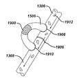
- aperture 1602 is closed and an external ring clamp 1614 is applied between the tissue surrounding reservoir 1610 and the remainder of intestine 8 such that reservoir 1610 is maintained within the dead end branch portion formed and catheter 1612 is positioned in the flow path of intestine 8 in order to provide a slow drip therapeutic substance which will initiate an intestinal braking effect and thereby create or maintain a sensation of satiety in the patient.
Abstract
Methods and devices create an intestinal braking effect, are non-invasive or minimally invasive, and may be reversible. These methods and devices are accomplished via stabilized implantable systems, and ingestible pills. In one embodiment, the implantable system comprises a device delivering a therapeutic substance to a target location within the gastrointestinal tract of a patient in order to initiate an intestinal braking effect which would promote sensations of satiety and stimulate excess weight loss for the patient.
Description
This application claims priority to U.S. Provisional Patent Application Ser. No. 61/348,276, entitled “Intestinal Brake Inducing Intraluminal Therapeutic Substance Eluting Devices and Methods,” filed May 26, 2010, the disclosure of which is incorporated by reference herein.
The present invention relates to methods and devices that elute a therapeutic substance which aid in inducing an intestinal braking effect.
When food content enters the intestines, an intestinal braking effect occurs which helps to slow the passage of this food content therethrough in order to aid in the absorption of nutrients to in the body. Intestinal brake has been shown to initiate satiation more quickly and is theorized to play an important role in the effectiveness (both Excess Weight Loss (EWL) and comorbidity resolution) of Roux-En-Y Gastric Bypass (RYGB) surgery. Procedures such as ileal transposition have been developed based on the concept of delivery of substances with rich nutrient/caloric content to the ileum and have been shown to be effective in numerous animal models. However, known methods tend to be overly invasive and often require a permanent perforation in the intestinal lumen. Accordingly, there is a need for creating an intestinal braking effect which is non-invasive or minimally invasive, and which may be reversible.
The present invention generally provides means for creating an intestinal braking effect which are non-invasive or minimally invasive and which may be reversible. Numerous methods and devices are disclosed herein for accomplishing this effect. These methods and devices fall under three general categories: implantable systems, methods of stabilization of implants, and ingestible pills.
Numerous implantable systems for creating an intestinal braking effect are disclosed herein. These implantable systems may include means for eluting a therapeutic substance and are typically placed at or proximal to a desired delivery site. Examples of therapeutic substances include nutrients, hormones, hormone eluting cell stimulants, hormone eluting cell deterrents and the like. Preferably, the placement of these systems would be accomplished by non-invasive or minimally invasive means. These systems would typically comprise at least two sub-systems: an implant and a deployment device. Examples of such implants include intestinal drug delivery stents, multi-reservoir stents, refillable intestinal drug delivery stents, delivery systems for nutrient binding materials, chime holding stents, and extraluminal choke rings, all of which will be discussed in greater detail later herein. Examples of such deployment devices include inflatable delivery mechanisms, guide wire extenders, and self expanding stents, all of which will be discussed in greater detail later herein.
The methods of stabilization of implants generally comprise creating an artificially formed dead end branch or a loop with anastomosis in the intestines, both of which will be discussed in greater detail later herein. These stabilization methods are generally minimally invasive procedures which allow the intestines to remain vascularized and connected to mesentery. This allows any accompanying implant to establish a continued impact on hormonal activity of the intestines, thereby increasing the effectiveness of this treatment.
Several ingestible pills creating an intestinal braking effect are disclosed herein. In general, these specialized ingestible pills may be utilized to deliver therapeutic substances to targeted locations in order to create the desired intestinal braking effect. These pills get around the negative side effects associated with known systemic dosing of therapeutic substances for weight loss. Additionally, since these pills may be administered orally, this method for creating an intestinal brake has the added benefit of being non-invasive. Examples of such ingestible pills include a fat pill with nanochannels, a pressure wave pill, a stomach coating pill, and a pill to increase peristalsis, all of which will be discussed in greater detail later herein.
As may be appreciated, any of the aforementioned devices and methods disclosed herein may be practiced either alone or in combination with any of the other disclosed devices and methods, where practical, without departing from the scope of the present invention, to achieve the desired effect of creating an intestinal brake which is non-invasive or minimally invasive, and may be reversible in nature.
The invention will be more fully understood from the following detailed description taken in conjunction with the accompanying drawings, in which:
Certain exemplary embodiments will now be described to provide an overall understanding of the principles of the structure, function, manufacture, and use of the devices and methods disclosed herein. One or more examples of these embodiments are illustrated in the accompanying drawings. Those skilled in the art will understand that the devices and methods specifically described herein and illustrated in the accompanying drawings are non-limiting exemplary embodiments and that the scope of the present invention is defined solely by the claims. For example, the features illustrated or described in connection with one exemplary embodiment may be combined with the features of other embodiments. Such modifications and variations are intended to be included within the scope of the present invention.
In regard to FIG. 1 , numerous alternatives are envisioned. For example, in one embodiment, implant 100 may include means to create “pulsations” of therapeutic substances rather than simply providing a constant release of these therapeutic substances. Accordingly, implant 100 may be constructed in a manner which provides alternating layers of therapeutic substance containing polymers and non-therapeutic substance containing polymers. Similarly, the alternating layers may comprise layers containing different dosings or concentrations of the therapeutic substances or different therapeutic substances from the surrounding layers. This may for example create a feeling of satiety, then a reduction in that feeling, or may help maintain the effectiveness of implant 100 through time. Further, the therapeutic substance utilized in implant 100 can be tailored to suit the intended location of the stent, taking into account factors such pH level exposure which may alter the life span of implant 100. Additionally, implant 100 may be configured to deliver an electrical stimulation to the GI tract at a location such as the ileum, and further may elute linoleic acid amongst its therapeutic substances. Non-limiting disclosure of the benefits of electrical stimulation of the ileum in the presence of linoleic acid in order to increase glucagon-like peptide 1 (GLP-1) expression can be found in U.S. Patent Application No. US2010/0056948 A1, published Mar. 4, 2010, entitled STIMULATION OF SATIETY HORMONE RELEASE, which is incorporated herein by reference in its entirety. In yet another embodiment, implant 100 may comprise an intestinal stent containing an active substance such as PPY or GLP-1 andoxytomodulin placed at the ileum. Further, the stent may be in the form of a metal (e.g., cobalt chromium, stainless steel, Nitinol, etc.) or absorbable polymer ring or mesh affixed to the gastrointestinal (GI) tract by sutures. The active substance may be a synthetic which is analogous to a human hormone or animal derived hormone.
The device and procedure outlined herein with respect to FIG. 1 is intended to induce satiety by introducing a therapeutic substance to activate an intestinal braking effect via a therapeutic substance eluting implant 100. The procedure has the further benefit of being non-invasive or minimally invasive, as well as being a reversible procedure should the patient or physician so desire. There are no anatomical changes to the GI tract, and placement of implant 100 may be realized endoluminally via a flexible endoscope or flexible endoscopic platform. Implant 100 may be delivered through a working channel or over the outside of the flexible endoscopic platform. Implant 100 may be delivered in collapsed or expanded state and delivered to the desired location within the GI tract either transorally or transanally. Further, the dosings and concentrations of the therapeutic substance(s) eluted by implant 100 may be tailored to meet the individual needs of the patient and may further be enhanced to vary over time and may be localized to control the delivery of hormone triggers to the desired receptors.
In regard to FIG. 4 , numerous alternatives are envisioned. For example, in one embodiment, reservoir 202 may be attached to a micro-pump which would release therapeutic substance automatically at predetermined points during the day in order to induce an intestinal braking effect which would help to create or maintain a sensation of satiety These smaller doses are distributed along a more continuous schedule and serve to maintain the feeling of satiety longer through prolonged addition of nutrients to the lower GI tract. As may be appreciated, additional reservoirs and pumps may be added to the system described above to deliver the desired therapeutic substance. In another embodiment, reservoir 202 may be a degradable therapeutic substance infused foam material that may be injected behind implant 200 to fill the gap created by the shape of implant 200. Over time, the foam material would release the therapeutic substance to induce an intestinal braking effect. This foam material could be re-injected via a flexible member during an annual colonoscopy. In yet another embodiment, reservoir 202 may be constructed from a semi-permeable membrane that would leach out a therapeutic substance over time. Similar to the previous embodiment disclosed, this reservoir could be refilled by means of a flexible member inserted during an annual colonoscopy procedure. For example, the flexible member may comprise a Huber needle at one end which may be attached via tubing to a secondary reservoir, such as a saline bag, external to the patient during the colonoscopy. In still another embodiment, reservoir 202 may comprise a swallowable reservoir that is captured by implant 200. In one embodiment, implant 200 may be in the form of a stent having tines that protrude into intestine 8 and capture reservoir 202 as it is brought into position by the natural peristalsis of the digestive cycle. Reservoir 202 may be in the form of a hollow cylinder which allows chyme to pass therethrough, but contain a therapeutic substance in the reservoir body. The therapeutic substance may then be released via slow perfusion, a small leak or a self-contained pump system. As the therapeutic substance is released, the diameter of reservoir 202 may decrease enough to allow it to pass through implant 200. A replacement reservoir could then be swallowed and the process would repeat.
In another embodiment a chyme holding implant is provided. FIG. 6 is a graph representing chyme levels in the body for a patient with and without a chyme holding implant. The graph on the left of FIG. 6 illustrates typical chyme levels in the body during the day without a chyme holding stent. As may be appreciated, chyme levels are highest shortly after a meal and decrease over time, eventually crossing the hunger threshold which induces a sensation of hunger in the patient. A more desirable graph is illustrated on the right of FIG. 6 where the chyme levels are maintained above the hunger threshold, thereby maintaining a sensation of satiety in the patient throughout the day. One means for creating such a graph is through the implantation of a chyme holding implant within the intestine which would act to hold a portion of chyme therein to prevent its movement through the intestines, such that chyme is in chemical and/or biological contact with the intestinal cells responsible for intestinal brake, thereby inducing an intestinal braking effect. In one embodiment, chyme would be held long enough so that chyme from one meal would remain into the next. Alternatively, chyme may be held for longer periods of time if so desired. In another embodiment, the implant protects the chyme therein from further digestion through the use of chemical or mechanical means. By holding chyme from one meal to the next, the GI tract would be tricked to behave as if food had just been ingested due to the chyme's tendency to induce the intestinal brake. This would allow the patient to eat less and achieve a desired weight loss.
In regards to the information disclosed in the graph of FIG. 25 , it is desirable to treat a patient with a pill which creates a coating within the stomach that helps to induce an intestinal braking effect. In one embodiment, such a pill would accelerate the delivery of fatty acid compounds and/or other therapeutic substances to the body to enable a reduction in food consumption or the sensation of hunger in a patient. In one embodiment, when such a pill is ingested, chemical compounds which terminate in long chain fatty acids are contained within the pill and act to bind to the interior walls of the stomach at acidic pH levels. Upon initial consumption of a meal, compounds release which act to neutralize the pH levels in the stomach. The bound chemical compounds are then released from the stomach walls into the stomach in high concentrations at the start of the meal, thus allowing for a more rapid stimulation of the ileum to initiate an intestinal braking effect. It may be desirable to include longer chained fatty acids such as palmitic, lignoceric acid, and hexacosanic acid in order to decrease the digestibility of the substance, thereby increasing the likelihood that the substance reaches the ileum.
One skilled in the art will appreciate further features and advantages of the invention based on the above-described embodiments. Accordingly, the invention is not to be limited by what has been particularly shown and described, except as indicated by the appended claims. All publications and references cited herein are expressly incorporated herein by reference in their entirety.
Claims (3)
1. A method of inducing satiety comprising:
a. implanting a stent within a lumen of a gastrointestinal tract;
b. retaining a portion of chyme that flows by the stent within a body of said stent;
c. re-releasing the retained chyme from said stent into the gastrointestinal tract at a predetermined rate slower than a rate caused by natural peristalsis; and
d. performing at least one additional step, the at least one additional step comprising, stabilizing said stent without disturbing vascularization of the intestines by performing a procedure selected from:
i. creating an artificially formed dead end branch,
ii. forming a loop with anastamosis in the intestines, and
iii. a combination thereof.
2. The method of claim 1 wherein said step of retaining a portion of chyme that flows by the stent within a body of said stent comprises absorbing said chyme within said stent.
3. The method of claim 1 wherein said step of retaining a portion of chyme that flows by the stent within a body of said stent comprises physically obstructing said chyme within said stent.
Priority Applications (3)
| Application Number | Priority Date | Filing Date | Title |
|---|---|---|---|
| US13/105,029 US8603023B2 (en) | 2010-05-26 | 2011-05-11 | Intestinal brake inducing intraluminal therapeutic substance eluting devices and methods |
| PCT/US2011/037678 WO2011149893A2 (en) | 2010-05-26 | 2011-05-24 | Intestinal brake inducing intraluminal therapeutic substance eluting devices and methods |
| US14/100,218 US10383754B2 (en) | 2010-05-26 | 2013-12-09 | Intestinal brake inducing intraluminal therapeutic substance eluting devices and methods |
Applications Claiming Priority (2)
| Application Number | Priority Date | Filing Date | Title |
|---|---|---|---|
| US34827610P | 2010-05-26 | 2010-05-26 | |
| US13/105,029 US8603023B2 (en) | 2010-05-26 | 2011-05-11 | Intestinal brake inducing intraluminal therapeutic substance eluting devices and methods |
Related Child Applications (1)
| Application Number | Title | Priority Date | Filing Date |
|---|---|---|---|
| US14/100,218 Continuation US10383754B2 (en) | 2010-05-26 | 2013-12-09 | Intestinal brake inducing intraluminal therapeutic substance eluting devices and methods |
Publications (2)
| Publication Number | Publication Date |
|---|---|
| US20110295180A1 US20110295180A1 (en) | 2011-12-01 |
| US8603023B2 true US8603023B2 (en) | 2013-12-10 |
Family
ID=44626913
Family Applications (2)
| Application Number | Title | Priority Date | Filing Date |
|---|---|---|---|
| US13/105,029 Active 2031-12-05 US8603023B2 (en) | 2010-05-26 | 2011-05-11 | Intestinal brake inducing intraluminal therapeutic substance eluting devices and methods |
| US14/100,218 Expired - Fee Related US10383754B2 (en) | 2010-05-26 | 2013-12-09 | Intestinal brake inducing intraluminal therapeutic substance eluting devices and methods |
Family Applications After (1)
| Application Number | Title | Priority Date | Filing Date |
|---|---|---|---|
| US14/100,218 Expired - Fee Related US10383754B2 (en) | 2010-05-26 | 2013-12-09 | Intestinal brake inducing intraluminal therapeutic substance eluting devices and methods |
Country Status (2)
| Country | Link |
|---|---|
| US (2) | US8603023B2 (en) |
| WO (1) | WO2011149893A2 (en) |
Cited By (14)
| Publication number | Priority date | Publication date | Assignee | Title |
|---|---|---|---|---|
| US10383754B2 (en) | 2010-05-26 | 2019-08-20 | Ethicon Endo-Surgery, Inc. | Intestinal brake inducing intraluminal therapeutic substance eluting devices and methods |
| US10596021B2 (en) | 2016-12-23 | 2020-03-24 | Ganz Brake, Llc | Obesity treatment devices, systems, and methods |
| US10813737B2 (en) | 2018-03-07 | 2020-10-27 | Torax Medical, Inc. | MRI compatible magnetic sphincter augmentation device |
| US10828064B2 (en) | 2018-03-01 | 2020-11-10 | Torax Medical, Inc. | Laparoscopic sizing instrument |
| US10842496B2 (en) | 2018-12-17 | 2020-11-24 | Ethicon Llc | Implantable sphincter assistance device with tuned magnetic features |
| US10945738B2 (en) | 2018-03-07 | 2021-03-16 | Torax Medical, Inc. | Tunable magnetic sphincter augmentation device |
| US11051931B2 (en) | 2018-10-31 | 2021-07-06 | Cilag Gmbh International | Active sphincter implant to re-route flow through gastrointestinal tract |
| US11071619B2 (en) | 2018-12-17 | 2021-07-27 | Cilag Gmbh International | Coupling assembly for implantable sphincter assistance device |
| US11298136B2 (en) | 2018-12-19 | 2022-04-12 | Cilag Gmbh International | Implantable sphincter assistance device with deformable elements |
| US11324512B2 (en) | 2018-10-26 | 2022-05-10 | Torax Medical, Inc. | Magnetic sphincter augmentation device for urinary incontinence |
| US11376146B2 (en) | 2018-12-17 | 2022-07-05 | Cilag Gmbh International | Tissue interface features for implantable sphincter assistance device |
| US11399928B2 (en) | 2018-12-19 | 2022-08-02 | Cilag Gmbh International | Linking elements for implantable sphincter assistance device |
| US11464660B2 (en) | 2016-12-23 | 2022-10-11 | Ganz Brake, Llc | Obesity treatment devices, systems, and methods |
| US11478347B2 (en) | 2018-12-17 | 2022-10-25 | Cilag Gmbh International | Sphincter sizing instrument |
Families Citing this family (4)
| Publication number | Priority date | Publication date | Assignee | Title |
|---|---|---|---|---|
| US7097665B2 (en) | 2003-01-16 | 2006-08-29 | Synecor, Llc | Positioning tools and methods for implanting medical devices |
| US20130325042A1 (en) * | 2012-05-31 | 2013-12-05 | Izhak Fabian | Pylorus plug and anastomosis |
| US20170128187A1 (en) * | 2017-01-24 | 2017-05-11 | Dr. Behrad Ziapour | Anti-intussusception ileal stent and its use as an anti-hyperglycemic method |
| KR102068887B1 (en) * | 2018-02-14 | 2020-01-21 | 인제대학교 산학협력단 | Medical anti-cancer stent unit |
Citations (10)
| Publication number | Priority date | Publication date | Assignee | Title |
|---|---|---|---|---|
| US5163952A (en) | 1990-09-14 | 1992-11-17 | Michael Froix | Expandable polymeric stent with memory and delivery apparatus and method |
| US6824561B2 (en) | 1998-04-30 | 2004-11-30 | Medtronic, Inc. | Implantable system with drug-eluting cells for on-demand local drug delivery |
| WO2006020370A2 (en) | 2004-08-09 | 2006-02-23 | Baronova, Inc. | Devices and methods for pyloric anchoring |
| US20060142794A1 (en) | 2003-02-19 | 2006-06-29 | Mnemoscience Gmbh | Self-expanding device for the gastrointestinal or urogenital area |
| US20070265598A1 (en) | 2004-09-30 | 2007-11-15 | Duocure, Inc. | Device and Method for Treating Weight Disorders |
| US20070293885A1 (en) * | 2004-02-26 | 2007-12-20 | Binmoeller Kenneth F | Methods and devices to curb appetite and/or to reduce food intake |
| US20100056948A1 (en) | 2008-08-26 | 2010-03-04 | Hornby Pamela J | Stimulation of Satiety Hormone Release |
| US20110105985A1 (en) * | 2009-10-29 | 2011-05-05 | Elmer Lucas B | Treatment For Metabolic Disorders By Diverting Bile To the Circulatory System |
| US20120041465A1 (en) * | 2009-04-30 | 2012-02-16 | Tidhar Shalon | Devices and methods for treating gastrointestinal and metabolic disorders |
| US8252337B2 (en) | 2008-10-23 | 2012-08-28 | National Health Research Institutes | Charged mesoporous silica nanoparticle-based drug delivery system for controlled release and enhanced bioavailability |
Family Cites Families (9)
| Publication number | Priority date | Publication date | Assignee | Title |
|---|---|---|---|---|
| GB2380595B (en) * | 2001-10-02 | 2005-06-15 | Flipperdisc Ltd | An optically readable carrier |
| US6981978B2 (en) * | 2002-08-30 | 2006-01-03 | Satiety, Inc. | Methods and devices for maintaining a space occupying device in a relatively fixed location within a stomach |
| US20050247320A1 (en) * | 2003-10-10 | 2005-11-10 | Stack Richard S | Devices and methods for retaining a gastro-esophageal implant |
| EP1570752B1 (en) * | 2004-03-06 | 2008-07-02 | Cognis IP Management GmbH | Verwendung von ungesättigten Fettsäuren zur Verringerung des Appetits oder der Essensaufnahme |
| US7417307B2 (en) * | 2005-07-29 | 2008-08-26 | Hewlett-Packard Development Company, L.P. | System and method for direct-bonding of substrates |
| US8551118B2 (en) * | 2007-07-18 | 2013-10-08 | Ethicon Endo-Surgery, Inc. | Hybrid endoscopic/laparoscopic method for forming serosa to serosa plications in a gastric cavity |
| US20110029000A1 (en) * | 2007-10-26 | 2011-02-03 | Blue Surgical Ltd. | In vivo suture assemblies |
| US8603023B2 (en) | 2010-05-26 | 2013-12-10 | Ethicon Endo-Surgery, Inc. | Intestinal brake inducing intraluminal therapeutic substance eluting devices and methods |
| US20120165604A1 (en) * | 2010-12-22 | 2012-06-28 | Ethicon Endo-Surgery, Inc. | Endoluminal fold creation |
-
2011
- 2011-05-11 US US13/105,029 patent/US8603023B2/en active Active
- 2011-05-24 WO PCT/US2011/037678 patent/WO2011149893A2/en active Application Filing
-
2013
- 2013-12-09 US US14/100,218 patent/US10383754B2/en not_active Expired - Fee Related
Patent Citations (10)
| Publication number | Priority date | Publication date | Assignee | Title |
|---|---|---|---|---|
| US5163952A (en) | 1990-09-14 | 1992-11-17 | Michael Froix | Expandable polymeric stent with memory and delivery apparatus and method |
| US6824561B2 (en) | 1998-04-30 | 2004-11-30 | Medtronic, Inc. | Implantable system with drug-eluting cells for on-demand local drug delivery |
| US20060142794A1 (en) | 2003-02-19 | 2006-06-29 | Mnemoscience Gmbh | Self-expanding device for the gastrointestinal or urogenital area |
| US20070293885A1 (en) * | 2004-02-26 | 2007-12-20 | Binmoeller Kenneth F | Methods and devices to curb appetite and/or to reduce food intake |
| WO2006020370A2 (en) | 2004-08-09 | 2006-02-23 | Baronova, Inc. | Devices and methods for pyloric anchoring |
| US20070265598A1 (en) | 2004-09-30 | 2007-11-15 | Duocure, Inc. | Device and Method for Treating Weight Disorders |
| US20100056948A1 (en) | 2008-08-26 | 2010-03-04 | Hornby Pamela J | Stimulation of Satiety Hormone Release |
| US8252337B2 (en) | 2008-10-23 | 2012-08-28 | National Health Research Institutes | Charged mesoporous silica nanoparticle-based drug delivery system for controlled release and enhanced bioavailability |
| US20120041465A1 (en) * | 2009-04-30 | 2012-02-16 | Tidhar Shalon | Devices and methods for treating gastrointestinal and metabolic disorders |
| US20110105985A1 (en) * | 2009-10-29 | 2011-05-05 | Elmer Lucas B | Treatment For Metabolic Disorders By Diverting Bile To the Circulatory System |
Non-Patent Citations (2)
| Title |
|---|
| International Search Report dated Jun. 19, 2012 for Application No. PCT/US2011/037678. |
| Simonian, H.P. et al., "Regional postprandial differences in pH within the stomach and gastroesophageal junction," Digestive Diseases and Sciences, vol. 50(12) (2005) pp. 2276-2285(Abstract). |
Cited By (15)
| Publication number | Priority date | Publication date | Assignee | Title |
|---|---|---|---|---|
| US10383754B2 (en) | 2010-05-26 | 2019-08-20 | Ethicon Endo-Surgery, Inc. | Intestinal brake inducing intraluminal therapeutic substance eluting devices and methods |
| US10596021B2 (en) | 2016-12-23 | 2020-03-24 | Ganz Brake, Llc | Obesity treatment devices, systems, and methods |
| US11464660B2 (en) | 2016-12-23 | 2022-10-11 | Ganz Brake, Llc | Obesity treatment devices, systems, and methods |
| US10828064B2 (en) | 2018-03-01 | 2020-11-10 | Torax Medical, Inc. | Laparoscopic sizing instrument |
| US11439431B2 (en) | 2018-03-01 | 2022-09-13 | Cilag Gmbh International | Laparoscopic sizing instrument |
| US10813737B2 (en) | 2018-03-07 | 2020-10-27 | Torax Medical, Inc. | MRI compatible magnetic sphincter augmentation device |
| US10945738B2 (en) | 2018-03-07 | 2021-03-16 | Torax Medical, Inc. | Tunable magnetic sphincter augmentation device |
| US11324512B2 (en) | 2018-10-26 | 2022-05-10 | Torax Medical, Inc. | Magnetic sphincter augmentation device for urinary incontinence |
| US11051931B2 (en) | 2018-10-31 | 2021-07-06 | Cilag Gmbh International | Active sphincter implant to re-route flow through gastrointestinal tract |
| US11071619B2 (en) | 2018-12-17 | 2021-07-27 | Cilag Gmbh International | Coupling assembly for implantable sphincter assistance device |
| US11376146B2 (en) | 2018-12-17 | 2022-07-05 | Cilag Gmbh International | Tissue interface features for implantable sphincter assistance device |
| US10842496B2 (en) | 2018-12-17 | 2020-11-24 | Ethicon Llc | Implantable sphincter assistance device with tuned magnetic features |
| US11478347B2 (en) | 2018-12-17 | 2022-10-25 | Cilag Gmbh International | Sphincter sizing instrument |
| US11298136B2 (en) | 2018-12-19 | 2022-04-12 | Cilag Gmbh International | Implantable sphincter assistance device with deformable elements |
| US11399928B2 (en) | 2018-12-19 | 2022-08-02 | Cilag Gmbh International | Linking elements for implantable sphincter assistance device |
Also Published As
| Publication number | Publication date |
|---|---|
| US20110295180A1 (en) | 2011-12-01 |
| WO2011149893A3 (en) | 2012-08-02 |
| US10383754B2 (en) | 2019-08-20 |
| US20140155807A1 (en) | 2014-06-05 |
| WO2011149893A2 (en) | 2011-12-01 |
Similar Documents
| Publication | Publication Date | Title |
|---|---|---|
| US10383754B2 (en) | Intestinal brake inducing intraluminal therapeutic substance eluting devices and methods | |
| US8876761B2 (en) | Intestinal brake inducing intraluminal therapeutic substance eluting devices and methods | |
| US8636751B2 (en) | Methods and devices for the rerouting of chyme to induce intestinal brake | |
| US11382782B2 (en) | Methods and devices to curb appetite and/or to reduce food intake | |
| US20110295178A1 (en) | Intestinal Brake Inducing Intraluminal Therapeutic Substance Eluting Devices and Methods | |
| JP4426852B2 (en) | Saturation device and method | |
| US9872786B2 (en) | Gastro-esophageal implants | |
| US8366650B2 (en) | Biliary/pancreatic shunt device and method for treatment of metabolic and other diseases | |
| CN101810524B (en) | Satiation devices | |
| US8414559B2 (en) | Gastroretentive duodenal pill | |
| CA2652419C (en) | Improvements in methods and devices to curb appetite and/or reduce food intake | |
| US20100114150A1 (en) | Duodenal stimulation devices and methods for the treatment of conditions relating to eating disorders | |
| WO2008028037A2 (en) | Distender device and method for treatment of obesity and metabolic and other diseases | |
| US20110295054A1 (en) | Method of Filling an Intraluminal Reservoir with a Therapeutic Substance | |
| US10603490B2 (en) | Temporarily implantable GI sensor and stimulator and related methods |
Legal Events
| Date | Code | Title | Description |
|---|---|---|---|
| AS | Assignment |
Owner name: ETHICON ENDO-SURGERY, INC., OHIO Free format text: ASSIGNMENT OF ASSIGNORS INTEREST;ASSIGNORS:ALBRECHT, THOMAS E.;ALDRIDGE, JEFFREY L.;CONLON, SEAN P.;AND OTHERS;SIGNING DATES FROM 20110520 TO 20110620;REEL/FRAME:026576/0151 |
|
| STCF | Information on status: patent grant |
Free format text: PATENTED CASE |
|
| FPAY | Fee payment |
Year of fee payment: 4 |
|
| MAFP | Maintenance fee payment |
Free format text: PAYMENT OF MAINTENANCE FEE, 8TH YEAR, LARGE ENTITY (ORIGINAL EVENT CODE: M1552); ENTITY STATUS OF PATENT OWNER: LARGE ENTITY Year of fee payment: 8 |