US8340347B2 - Information processing apparatus and information processing method - Google Patents
Information processing apparatus and information processing method Download PDFInfo
- Publication number
- US8340347B2 US8340347B2 US12/624,293 US62429309A US8340347B2 US 8340347 B2 US8340347 B2 US 8340347B2 US 62429309 A US62429309 A US 62429309A US 8340347 B2 US8340347 B2 US 8340347B2
- Authority
- US
- United States
- Prior art keywords
- area
- feature value
- area feature
- image
- image data
- Prior art date
- Legal status (The legal status is an assumption and is not a legal conclusion. Google has not performed a legal analysis and makes no representation as to the accuracy of the status listed.)
- Expired - Fee Related, expires
Links
Images


Classifications
-
- G—PHYSICS
- G06—COMPUTING; CALCULATING OR COUNTING
- G06T—IMAGE DATA PROCESSING OR GENERATION, IN GENERAL
- G06T1/00—General purpose image data processing
- G06T1/0021—Image watermarking
- G06T1/0028—Adaptive watermarking, e.g. Human Visual System [HVS]-based watermarking
-
- G—PHYSICS
- G06—COMPUTING; CALCULATING OR COUNTING
- G06T—IMAGE DATA PROCESSING OR GENERATION, IN GENERAL
- G06T1/00—General purpose image data processing
- G06T1/0021—Image watermarking
- G06T1/005—Robust watermarking, e.g. average attack or collusion attack resistant
- G06T1/0064—Geometric transfor invariant watermarking, e.g. affine transform invariant
-
- G—PHYSICS
- G06—COMPUTING; CALCULATING OR COUNTING
- G06T—IMAGE DATA PROCESSING OR GENERATION, IN GENERAL
- G06T2201/00—General purpose image data processing
- G06T2201/005—Image watermarking
- G06T2201/0201—Image watermarking whereby only tamper or origin are detected and no embedding takes place
Definitions
- the present invention relates to a technique of guaranteeing the integrity of digital data.
- Digital cameras and the like are recently widespread, which record captured images in a recording medium not as conventional silver halide photos or 8-mm film but as digital image data.
- Insurance companies which handle photos of evidence in tasks concerning accidents or construction firms which handle the records of the progress at the sites of construction also think of using digital image data.
- digital image data is easy to alter using, e.g., a commercially available photo retouch tool. For this reason, digital image data is less reliable than conventional silver halide photos and therefore poor in capability as evidence.
- a method as disclosed in patent reference 1 has been proposed. According to this reference, a digital camera holds secret information in advance. Upon capturing an image, the digital camera signs the digital image data using the secret information. After the image capturing, validation processing is performed using the generated signature information, thereby guaranteeing the integrity of the digital image data.
- an apparatus for generating validation data to validate alteration of image data includes a calculator which calculates a feature value of an image represented by the image data, the feature value being unchangeable when the image rotates; and a validation data generator which generates, based on the calculated feature value, validation data to validate alteration of the image data.
- FIGS. 1A and 1B are block diagrams for explaining arrangements of an image input apparatus according to the first embodiment
- FIGS. 2A and 2B are block diagrams for explaining arrangement of an image validation apparatus according to the first embodiment
- FIGS. 3A and 3B are flowcharts illustrating procedures of image input processing according to the first embodiment
- FIGS. 4A and 4B are flowcharts illustrating procedures of image validation processing according to the first embodiment
- FIG. 5 is a view for explaining an example of validation processing according to the first embodiment
- FIGS. 6A to 6C are flowcharts for explaining the procedure of area separation processing and a view showing a feature value list according to the second embodiment, respectively;
- FIG. 7 is a view for explaining an example of area separation processing according to the second embodiment.
- FIG. 8 is a block diagram for explaining the arrangement of the image input apparatus according to the first embodiment.
- FIG. 9 is a block diagram for explaining the arrangement of a computer according to the first embodiment.
- FIG. 10 is a view for explaining an example of validation processing according to the first embodiment
- FIG. 11 is a block diagram for explaining the arrangement of an image validation apparatus according to a modification of the first embodiment
- FIGS. 12A and 12B are views for explaining first area feature values and second area feature values according to the first embodiment
- FIG. 13 is a block diagram showing the arrangement of an image input apparatus according to the second embodiment.
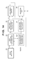
- FIG. 14 is a block diagram for explaining the arrangement of an image validation apparatus according to the second embodiment.
- FIGS. 15A to 15C are views for explaining examples of area separation processing according to another embodiment
- FIG. 16 is a block diagram for explaining the arrangement of an image input apparatus according to the modification of the first embodiment.
- FIG. 17 is a view for explaining the format of image data according to the embodiment.
- FIG. 8 is a block diagram showing the basic arrangement of an image input apparatus (information processing apparatus) adaptable to this embodiment.
- an image input apparatus 81 according to this embodiment includes a ROM 82 , storage memory 83 , work memory 84 , CPU 85 , operation unit 86 , optical system 87 , driving unit 88 , and I/F 89 . These units are connected by a bus 810 .
- the image input apparatus 81 is, e.g., a common digital camera which can store, in the storage memory 83 or the like, digital image data generated by the optical system 87 upon receiving an image capturing instruction input via the operation unit 86 .
- the ROM 82 is a read only memory which stores operation programs and shared information used for validation data generation in advance.
- the storage memory 83 stores processed image data.
- the work memory 84 temporarily stores image data. Compression and various kinds of arithmetic processes of the image data are executed on the work memory 84 .
- the CPU 85 Upon receiving an image capturing instruction, the CPU 85 performs various kinds of arithmetic processes such as image data compression processing and validation data generation in accordance with a program stored in the ROM 82 in advance.
- the operation unit 86 serves as a user interface to receive various kinds of instructions represented by an image capturing instruction from a user and various parameter settings.
- the optical system 87 includes an optical sensor using, e.g., as a charge coupled device (CCD) or a complementary metal oxide semiconductor (CMOS).
- CCD charge coupled device
- CMOS complementary metal oxide semiconductor
- the driving unit 88 performs mechanical operations used for image capturing under the control of the CPU 85 .
- the I/F 89 is an interface to an external device such as a memory card, a portable terminal, or a communication device and is used to transmit image data or validation data to these devices.
- FIG. 9 is a block diagram showing the basic arrangement of a host computer functioning as an image validation apparatus (information processing apparatus) according to this embodiment and the relation to its peripheral device.
- a host computer 91 is, e.g., a common personal computer.
- the host computer 91 can accumulate image data in an HD (Hard Disk) 96 , CD 97 , FD 98 , or DVD 99 or display accumulated image data or the like on a monitor 92 .
- the host computer 91 can also distribute these image data via, e.g., the Internet using a NIC 910 .
- Various user instructions are input from a pointing device 912 or a keyboard 913 .
- a bus 915 connects blocks to be described later inside the host computer 91 to enable transfer of various data.
- the monitor 92 can display various kinds of information from the host computer 91 .
- a CPU 93 can control the operations of the units in the host computer 91 or execute a program loaded to a RAM 95 .
- a ROM 94 stores a BIOS and boot programs.
- the RAM 95 temporarily stores programs and process target image data for processing of the CPU 93 .
- the OS and programs to be used by the CPU 93 to execute various kinds of processing to be described later are loaded to the RAM 95 .
- the HD 96 stores the OS and programs to be transferred to the RAM or the like and is also used by the apparatus to store or read out image data during the operation.
- the CD-ROM drive 97 can read out data from a CD-ROM (or CD-R or CD-R/W) that is an external storage medium, or write data on it.
- the FD drive 98 can also read- and write-access an FD (Floppy® disk), like the CD-ROM drive 97 .
- the DVD-ROM (DVD-RAM) drive 99 can also read-access a DVD-ROM or write-access a DVD-RAM, like the CD-ROM drive 97 .
- An I/F 911 connects the host computer 91 to the NIC 910 which connects, to a network such as the Internet, image data stored in the RAM 95 , HD 96 , CD-ROM 97 , FD 98 , or DVD 99 .
- the host computer 91 transmits or receives data to or from the Internet via the I/F 911 .
- An I/F 914 connects the pointing device 912 and the keyboard 913 to the host computer 91 .
- Various kinds of instructions input from the pointing device 912 or the keyboard 913 are input to the host computer 91 via the I/F 914 .
- the image input processing unit (function) of the image input apparatus 81 applied to the embodiment will be described below with reference to FIG. 1A . Note that functions available when the above-described image input apparatus 81 is powered on, and the OS is loaded to the work memory 84 will be explained below.
- the present invention is not limited to this, and the processing can be executed by the above-described host computer 91 .
- the respective processing units are implemented by corresponding programs, the CPU 93 which executes the programs, and peripheral hardware as needed.
- the image input apparatus 81 includes an image generator 11 , area separation processing unit 12 , first area feature value calculator 13 , second area feature value calculator 14 , area order sorter 15 , validation data generation processing unit 16 , and image output unit 17 .
- image input processing to be explained here may be implemented by software processing. In that case, the above-described units should be regarded as the concepts of functions used for the processing.
- the image generator 11 includes an optical sensor using, e.g., CMOS (complementary metal oxide semiconductor) or CCD (charge coupled device) in the optical system 87 , and a microprocessor for controlling the optical system.
- the image generator 11 acquires, as image information, a video signal generated by the optical system and the optical sensor, and forms image data I.
- the image data I generated by the image generator 11 is output to the area separation processing unit 12 and the image output unit 17 of the succeeding stage.
- the area separation processing unit 12 receives the image data I generated by the image generator 11 of the preceding stage, executes area separation processing of the received image data I, and outputs an area separation result R.
- the area separation processing unit 12 can automatically execute the area separation processing by referring to attributes such as color information and brightness information.
- attributes such as color information and brightness information.
- the shape of a separated area is not particularly defined, and separation is only being performed using the above-described attributes for area separation.
- the area separation processing can be done using an integration approach which repeatedly integrates subareas having similar features or a separation approach which starts from a whole image and repeatedly separates the image unless the features are uniform.
- An example of area separation processing is the k-means algorithm which is known well as an area separation method using color information or brightness information.
- An area separation method using the region growing method or watershed transformation is also known. The k-means algorithm and area separation using the region growing method or watershed transformation are well-known techniques for those skilled in the art, and a detailed description thereof will be
- the first area feature value calculator 13 receives the area separation result R of division by the area separation processing unit 12 of the preceding stage, calculates the first area feature value of each area based on the received area separation result R, and outputs calculated first area feature values P 1 .
- the area of each area is applied as the first area feature value.
- the present invention is not limited to this. More specifically, various feature values are applicable as the first area feature value if they do not change even after rotation of an image (or each area of an image) (do not depend on the coordinates of an image and are independent of the coordinate information of the image). Examples other than the area will be listed below.
- the second area feature value calculator 14 receives the area separation result R of division by the area separation processing unit 12 of the preceding stage, calculates the second area feature value of each area based on the received area separation result R, and outputs calculated second area feature values P 2 .
- the average value of the brightness values of each area is applied as the second area feature value.
- the present invention is not limited to this. More specifically, various feature values are applicable as the second area feature value if they do not change even after rotation of an image, like the first area feature values P 1 . Note that the first area feature value P 1 and the second area feature value P 2 are feature values of different types here.
- the area order sorter 15 receives the first area feature values P 1 and the second area feature values P 2 calculated by the first area feature value calculator 13 and the second area feature value calculator 14 of the preceding stage, respectively.
- the area order sorter 15 sorts the second area feature values P 2 using the relative relation of the first area feature values P 1 , and outputs sorted second area feature values S.
- a series of processes in the first area feature value calculator 13 , second area feature value calculator 14 , and area order sorter 15 will be described here using an example shown in FIGS. 12A and 12B .
- 121 represents an area number assigned to each of separated areas; 122 , the first area feature value P 1 calculated by the first area feature value calculator 13 ; and 123 , the second area feature value P 2 calculated by the second area feature value calculator 14 .
- the area order sorter 15 receives the first area feature values P 1 and the second area feature values P 2 and sorts the areas based on the first area feature values P 1 .
- FIG. 12B shows the sort result. In the example of FIG. 12B , the areas are sorted in descending order ( 125 in FIG. 12B ) of the first area feature values P 1 . As the result of sort, the areas are rearranged in the order of “2, 1, 3, 4, 7, 6, 5”, as indicated by 124 .
- the area order sorter 15 outputs “130, 180, 190, 120, 10, 50, and 100” as the sorted second area feature values S, as indicated by 126 .
- sorting is performed in descending order.
- the present invention is not limited to this. Sorting in ascending order and various kinds of other sorting methods of arranging areas in accordance with a predetermined rule are also included, as a matter of course.
- the validation data generation processing unit 16 receives the sorted second area feature values S output from the area order sorter 15 of the preceding stage. The validation data generation processing unit 16 then generates validation data Sign(S) based on a signature key Ks and the received sorted second area feature values S, and outputs the generated validation data Sign(S).
- a MAC Message Authentication Code
- a digital signature or the like is applicable as the validation data of this embodiment.
- Methods of generating a MAC or a digital signature are well-known techniques for those skilled in the art, and a detailed description thereof will be omitted.
- secret information for generating the MAC is input as the signature key Ks and used for MAC generation.
- the image input apparatus and the image validation apparatus to be described later share the signature key Ks.
- the ROM 82 in the image input apparatus and the ROM 94 in the image validation apparatus hold common secret information in advance.
- the validation data generation processing unit 16 uses the secret information as needed.
- the signature key Ks may be held in a tampering-resistant device such as an IC card.
- the IC card is connected to the image input apparatus and the image validation apparatus, and the validation data generation processing unit 16 may acquire and use the signature key Ks in the IC card.
- new secret information may be generated in the image input apparatus and used as the signature key Ks.
- the generated secret information is held in a tampering-resistant device such as an IC card or encrypted and transmitted to the image validation apparatus.
- secret information for generating the digital signature is input as the signature key Ks.
- the ROM 82 in the image input apparatus holds the signature key Ks in advance.
- the validation data generation processing unit 16 uses the signature key Ks as needed.
- the signature key Ks may be held in a tampering-resistant device such as an IC card.
- the IC card is connected to the image input apparatus, and the validation data generation processing unit 16 may acquire and use the signature key Ks in the IC card. Otherwise, a new signature key Ks may be generated in the image input apparatus and used.
- a public key corresponding to the signature key Ks used by the validation data generation processing unit 16 in the image validation apparatus is to be described later.
- the image output unit 17 of the succeeding stage adds the public key corresponding to the signature key Ks to the image data and transmits it to the image validation apparatus.
- the public key is held on a server (not shown). Information (e.g., URL) representing the public key holding position on the server is recorded in the image data.
- the image validation apparatus may acquire the public key from the server as needed using the information representing the holding position.
- a MAC or a digital signature is generated from the sorted second area feature values S as validation data.
- the present invention is not limited to this.
- the input sorted second area feature values S may directly be used as validation data.
- the input sorted second area feature values S are encrypted using secret information shared by the image validation apparatus in advance, and the encrypted sorted second area feature values S may be used as validation data.
- the image output unit 17 receives the image data I output from the image generator 11 of the preceding stage and the validation data Sign(S) output from the validation data generation processing unit 16 .
- the image output unit 17 adds the validation data Sign(S) to the image data I and outputs it.
- the validation data Sign(S) is added by recording it in the header of the image data I formatted to Exif or the like.
- the present invention is not limited to this.
- Various methods are available to add the validation data Sign(S) to the image data I.
- the validation data Sign(S) may be concatenated to the end of the image data I.
- the image output unit 17 may acquire, from the area separation processing unit 12 , the number n of areas separated by it, and add the number n of areas to the image data I.
- the number n of areas is added to the image data I, and an area separation processing unit 22 of the image validation apparatus ( FIG. 2A or 2 B) to be described later separates the image into areas in number equal to the number n of areas.
- the image input apparatus and the image validation apparatus readily obtain the same area separation result.
- the image input apparatus and the image validation apparatus may share the number n of areas in advance and perform area separation processing based on the shared number n of areas.
- FIG. 17 is a view illustrating the format of data output from the image output unit 17 .
- the validation data Sign(S) and the number n of areas are recorded in the header portion of image data formatted to Exif or the like, and output together with the image data.
- the image output unit 17 records the image data I in a storage medium such as a removable medium or transmits the image data I to a predetermined host via a wired or wireless network.
- FIG. 3A is a flowchart illustrating the procedure of the image capturing processing.
- the image generator 11 obtains the image data I (S 31 , i.e., capture image).
- the area separation processing unit 12 performs area separation processing of the image data I (S 32 , i.e., separate into areas).
- the first area feature value calculator 13 calculates the first area feature value P 1 of each of the separated areas (S 33 ).
- the second area feature value calculator 14 calculates the second area feature value P 2 of each of the separated areas (S 34 ).
- the area order sorter 15 sorts the second area feature values P 2 based on the first area feature values P 1 (S 35 ).
- the validation data generation processing unit 16 generates the validation data Sign(S) based on the sorted second area feature values S (S 36 ).
- the image output unit 17 composites the image data I and the validation data Sign(S) and outputs them (S 37 , i.e., output image).
- the image validation processing unit (function) of the image validation apparatus applied to the embodiment will be described below with reference to FIG. 2A .
- the image validation apparatus includes an image input unit 21 , area separation processing unit 22 , first area feature value calculator 23 , second area feature value calculator 24 , area order sorter 25 , and validation unit 26 .
- image validation processing to be explained here may be implemented by software processing. In that case, the above-described units should be regarded as the concepts of functions used for the processing. Referring to FIG.
- the image input unit 21 inputs image data I′ output from the above-described image input apparatus.
- image data I′ output from the image input apparatus is input via a removable medium and/or a network.
- the image data I′ is input to the image validation apparatus considering the possibility that the image data I output from the image input apparatus is altered halfway.
- the image input unit 21 also analyzes the header of the received image data I′, extracts added validation data Sign′(S), and outputs the extracted validation data Sign′(S).
- the validation data is represented by Sign′(S) considering the possibility that Sign(S) generated in the image input apparatus is altered halfway. Without alteration, Sign′(S) equals Sign(S).
- the processes to be executed in the area separation processing unit 22 , first area feature value calculator 23 , second area feature value calculator 24 , and area order sorter 25 are the same as those in the area separation processing unit 12 , first area feature value calculator 13 , second area feature value calculator 14 , and area order sorter 15 in FIG. 1A .
- the area separation processing unit 22 may acquire, from the image input unit 21 , the number n of areas added to the image data I and separate the image into areas in number equal to the number n of areas. At this time, the above-described image input apparatus and the image validation apparatus readily obtain the same area separation result.
- the image input apparatus and the image validation apparatus may share the number n of areas in advance and perform area separation processing based on the shared number n of areas.
- the validation unit 26 receives sorted second area feature values S′ output from the area order sorter 25 of the preceding stage, the validation data Sign′(S) extracted by the image input unit 21 , and a validation key Kv. Using the received data, the validation unit 26 validates whether the image data I′ has been altered, and outputs the validation result (OK/NG).
- the validation processing executed by the validation unit 26 corresponds to the above-described validation data generation processing unit 16 .
- the validation unit 26 executes the validation processing using the MAC. If the validation data generation processing unit 16 has generated a digital signature, the validation unit 26 executes the validation processing using the digital signature.
- the validation key Kv is secret information identical to the signature key Ks applied by the validation data generation processing unit 16 .
- the validation key Kv should be considered as the public key corresponding to the signature key Ks applied by the validation data generation processing unit 16 . Note that validation methods using a MAC or a digital signature are well-known techniques for those skilled in the art, and a detailed description thereof will be omitted.
- the sorted second area feature values S′ are validated using a MAC or a digital signature as validation data.
- the present invention is not limited to this. That is, the validation method is selected in accordance with the validation data generation method. For example, if the validation data corresponds to the input sorted second area feature values S themselves, the input sorted second area feature values S′ themselves are used as validation data and compared, thereby validating alteration of the image data.
- FIG. 4A is a flowchart illustrating the procedure of the image validation processing applicable to the embodiment.
- the image input unit 21 inputs the image data I′ (S 41 ).
- the area separation processing unit 22 performs area separation processing of the image data I′ (S 42 , i.e., separate into areas).
- the first area feature value calculator 23 calculates a first area feature value P 1 ′ of each of the separated areas (S 43 ).
- the second area feature value calculator 24 calculates a second area feature value P 2 ′ of each of the separated areas (S 44 ).
- the area order sorter 25 sorts the second area feature values P 2 ′ based on the first area feature values P 1 ′ (S 45 ). Using the sorted second area feature values S′ and the validation data Sign′(S), the validation unit 26 validates the presence/absence of alteration of the image data I′ (S 46 ). According to this embodiment, validation data is generated from the sorted second area feature values S generated using the area separation processing unit 12 , first area feature value calculator 13 , second area feature value calculator 14 , and area order sorter 15 .
- validation processing can succeed even when the image data I has undergone rotation processing between the image input apparatus and the image validation apparatus.
- rows 51 and 53 show various kinds of data concerning an original image and an image obtained by rotating the original image.
- the columns show, from the left, a validation target image, an area separation result, first area feature values, and sorted second area feature values.
- the validation target image corresponds to the image data I′ in FIG. 2A .
- the area separation result corresponds to an area separation result R′ in FIG. 2A .
- the first area feature values correspond to a state in which the first area feature values P 1 ′ in FIG.
- the sorted second area feature values correspond to the sorted second area feature values S′ in FIG. 2A .
- a number under each area represents a first area feature value.
- the area of each area is used as a first area feature value
- the average value of the brightness values of each area is used as a second area feature value.
- the rotated image 53 obtains the same area separation result as in the original image 51 . That is, areas identical to those obtained from the original image can be obtained from the rotated image 53 as well.
- the rotated image 53 obtains the same sort result as in the original image 51 . That is, upon sorting in descending order, the same area order as in the original image can be obtained in the rotated image 53 , too.
- validation processing can fail if the image data I has undergone alteration between the image input apparatus and the image validation apparatus. The principle will be explained using an example shown in FIG. 10 .
- FIG. 10 The principle will be explained using an example shown in FIG. 10 .
- the altered image obtains an area separation result different from that in the original image 51 .
- the sort result contains an area that does not exist in the original image. Consequently, sorted second area feature values different from those in the original image are obtained, and the validation processing fails.
- feature values of different types are used as the first area feature value P 1 and the second area feature value P 2 .
- the feature values applied in this embodiment not to “feature values which do not change even after rotation of an image” but to “feature values which do not change even after enlargement/reduction and rotation of an image” makes it possible to impart tolerance of enlargement/reduction to the validation data generated in the embodiment.
- the feature values which do not change even after enlargement/reduction and rotation of an image are the average value of brightness information, the average value of color information, the variance of brightness information, and the variance of color information in each area.
- the area separation processing unit 12 separates image data into a plurality of areas.
- the area separation processing unit 12 does not separate image data into a plurality of areas.
- the entire image is regarded as one area. Since the area order need not be sorted, the plurality of area feature values are unnecessary. That is, one area feature value is calculated for the whole image, and validation data is generated based on it.
- the type of area data and the method of generating validation data from the area feature value are the same as those described above.
- the area separation processing unit 12 , first area feature value calculator 13 , and area order sorter 15 in FIG. 1A are unnecessary.
- the first area feature value P 1 and the second area feature value P 2 calculated by the first area feature value calculator 13 and the second area feature value calculator 14 are feature values of different types.
- feature values of the same type may be used. Using feature values of the same type decreases the numbers of components and processes.
- An arrangement using feature values of the same type will be explained below with reference to FIGS. 11 and 16 .
- the arrangement of an image input apparatus according to this modification will be described first with reference to FIG. 16 .
- FIG. 16 is a block diagram for explaining the functions of the image input processing apparatus according to this modification.
- the modification is different from the first embodiment in an area feature value calculator 161 and an area order sorter 162 .
- the area feature value calculator 161 has the same arrangement as that of the first area feature value calculator 13 or the second area feature value calculator 14 of the first embodiment.
- the area order sorter 162 receives area feature values P calculated by the area feature value calculator 161 of the preceding stage, sorts the area feature values P, and outputs sorted area feature values S. That is, the area feature values P are directly sorted in this modification, although the area order sorter 15 of the first embodiment sorts the first area feature values P 1 using the second area feature values P 2 .
- FIG. 11 The arrangement of an image validation apparatus according to this modification will be described next with reference to FIG. 11 .
- FIG. 11 is a block diagram for explaining the functions of the image validation apparatus according to this modification.
- the modification is different from the first embodiment in an area feature value calculator 111 and an area order sorter 112 . Except the area feature value calculator 111 and the area order sorter 112 , the components and processes are the same as in the first embodiment, and a description thereof will not be repeated.
- the arrangement and process of the area feature value calculator 111 are the same as those of the above-described area feature value calculator 161 in FIG. 16 .
- the arrangement and process of the area order sorter 112 are the same as those of the above-described area order sorter 162 in FIG. 16 .
- the area order sorter 15 in FIG. 1 outputs the sorted second area feature values S, and the validation data generation processing unit 16 receives them to generate the validation data Sign(S).
- the magnitude relation between the area feature values included in the second area feature values S may be calculated, and validation data may be generated using the calculated magnitude relation.
- An example will be described below in which validation data is generated using the magnitude relation between the area feature values.
- the arrangement of an image input apparatus according to this modification will be explained first with reference to FIG. 1B . Except a magnitude relation calculator 18 , the components and processes in FIG. 1B are the same as in FIG. 1A described above, and a description thereof will not be repeated.
- the magnitude relation calculator 18 receives the sorted second area feature values S output from the area order sorter of the preceding stage, calculates the magnitude relation between the area feature values based on the received sorted second area feature values S, and outputs a calculated magnitude relation O.
- the validation data generation processing unit 16 of the succeeding stage receives the output magnitude relation O and calculates validation data Sign(O). Magnitude relation calculation processing to be executed in the magnitude relation calculator 18 will be described here.
- S(x) is an area feature value included in the sorted second area feature values S
- i and j are indices representing the second area feature values S
- O(x) is the calculated magnitude relation
- k is an index representing the magnitude relation.
- O(k) are concatenated and output as the magnitude relation O.
- the magnitude relation may not be calculated for all combinations of i and j.
- O(k) may be calculated for combinations selected at random using random numbers or predetermined combinations.
- FIG. 2B The arrangement of an image validation apparatus according to this modification will be explained next with reference to FIG. 2B . Except a magnitude relation calculator 27 , the components and processes in FIG. 2B are the same as in FIG. 2A described above, and a description thereof will not be repeated. The magnitude relation calculation processing to be executed in the magnitude relation calculator 27 is the same as in the magnitude relation calculator 18 in FIG. 1B , and a description thereof will not be repeated.
- step S 35 the magnitude relation calculator 18 calculates the magnitude relation O in step S 38 .
- validation data generation processing is executed in step S 36 based on the calculated magnitude relation.
- step S 45 the magnitude relation calculator 27 calculates a magnitude relation O′ in step S 47 .
- validation processing is executed in step S 46 using the calculated magnitude relation.
- validation data is generated based on not the sorted second area feature values but the magnitude relation between them, thereby improving the tolerance. More specifically, validation (i.e., determining that “image data has not been altered”) can succeed even when validation target image data has undergone various kinds of image processing such as ⁇ correction and contrast correction as well as rotation and reduction. This is because when validation target image data has undergone ⁇ correction or contrast correction, the sorted second area feature values themselves change, but the magnitude relation between them does not change.
- the image input apparatus transmits the number of separated areas to the image validation apparatus such that the number of separated areas in the image validation apparatus becomes equal to that in the image input apparatus.
- the present invention is not limited to this.
- the image input apparatus and the image validation apparatus only obtain the same area separation result if there is no alteration of an image.
- area separation is repeatedly executed.
- it may be determined whether to further execute or finish the area separation processing.
- a method will be described which determines, using the relation between area feature values obtained from the result of first area separation processing, whether to continue area separation processing.
- An image input apparatus 81 applied to the embodiment will be described below with reference to FIG. 13 .
- Image input processing to be explained here may be implemented by software processing.
- the above-described units should be regarded as the concepts of functions used for the processing.
- An area separation determination processing unit 131 is added, unlike the first embodiment. Except this, the components and processes are the same as in the first embodiment, and a description thereof will not be repeated.
- the area separation determination processing unit 131 determines whether an area separation result output from an area separation processing unit 12 of the preceding stage is appropriate.
- the area separation determination processing unit 131 Upon determining that it is appropriate, the area separation determination processing unit 131 outputs an area separation result R to a first area feature value calculator 13 and a second area feature value calculator 14 of the succeeding stage. On the other hand, upon determining that the area separation result is not appropriate, the area separation determination processing unit 131 requests the area separation processing unit 12 of the preceding stage to execute the area separation processing again.
- the area separation processing unit 12 separates image data I (S 61 ).
- the area separation determination processing unit 131 determines whether the first area feature value difference between the areas is larger than a predetermined threshold (S 62 ). If it is determined that the difference is equal to or smaller than the threshold, the area separation processing ends.
- the area separation determination processing unit 131 outputs the area separation result R to the first area feature value calculator 13 and the second area feature value calculator 14 of the succeeding stage. Otherwise, the process returns to step S 61 to execute the area separation processing again. Assume that in the above-described processing procedure shown in FIG.
- the area separation processing in step S 61 is executed based on, e.g., the average value of the brightness values of the areas.
- an area in which the average value of the brightness values after area separation does not change from that before as a result of area separation in step S 61 may not be separated by area re-separation in step S 61 even if it is determined in step S 62 that the feature value difference between areas is larger than the threshold.
- FIG. 6B a feature value list as shown in FIG. 6C is held in, e.g., a RAM 95 ( FIG. 9 ) in the order of feature value application in advance.
- the feature value registered first in the feature value list shown in FIG. 6C is set as the initial feature value (S 63 ).
- “the average value of brightness values” is set as the initial feature value.
- a value “1” is substituted for the number n 1 of areas (S 64 ). Since area separation processing has never been executed at this stage, the entire image is regarded as one area, and the number of areas is set to “1”.
- the image data I is separated into areas (S 65 ).
- the number n 2 of areas after area separation is calculated (S 66 ).
- the area separation determination processing unit 131 determines whether the first area feature value difference between the areas is larger than a predetermined threshold (S 62 ). If it is determined that the difference is equal to or smaller than the threshold, the area separation processing ends. The area separation determination processing unit 131 outputs the area separation result R to the first area feature value calculator 13 and the second area feature value calculator 14 of the succeeding stage. If it is determined that the difference is larger than the threshold, the process advances to step S 67 . In step S 67 , the area separation determination processing unit 131 calculates the difference between the number n 1 of areas and the number n 2 of areas calculated in steps S 64 and S 66 , and determines whether the calculated difference is smaller than the threshold.
- step S 68 Upon determining that it is smaller than the threshold, the feature value registered next in the above-described feature value list is set (S 68 ). The process advances to step S 69 .
- “the variance of brightness values” next to “the average value of brightness values” is set as the feature value.
- step S 69 the number n 2 of areas is substituted for n 1 . The process then returns to step S 65 .
- area separation processing can be performed using another feature value such as the variance of brightness values. This allows to further separate even an area which cannot be separated using a single feature value.
- the overall processing procedure of this embodiment is obtained by replacing step S 32 in FIG. 3A with the processing in FIG. 6A or 6 B.
- An example of area separation processing of this embodiment will be explained below with reference to FIG. 7 .
- reference numerals 71 , 72 , 73 , and 74 denote area separation results.
- the area separation result 71 is obtained by the first area separation processing.
- the area difference between the areas is calculated.
- area separation is further executed to obtain the area separation result 72 .
- This processing is repeated to obtain the area separation results 73 and 74 .
- the area separation result 74 in which the maximum value of the area difference is equal to or smaller than the predetermined threshold is output as the final area separation result.
- this embodiment uses the area difference for the area separation determination processing.
- the above-described feature value applicable to the first area feature value information concerning areas such as the number of areas included in an area separation result, or a relation such as a difference or a ratio between these pieces of information.
- An image validation apparatus 91 applied to the embodiment will be described below with reference to FIG. 14 .
- Image validation processing to be explained here may be implemented by software processing.
- the above-described units should be regarded as the concepts of functions used for the processing.
- An area separation determination processing unit 141 is added, unlike the first embodiment. Except this, the components and processes are the same as in the first embodiment, and a description thereof will not be repeated.
- the internal processing of the area separation determination processing unit 141 is the same as that of the above-described area separation determination processing unit 131 of this embodiment.
- the processing procedure of an area separation processing unit 22 and the area separation determination processing unit 141 according to this embodiment is also the same as in FIG. 6A or 6 B.
- the overall processing procedure of this embodiment is obtained by replacing step S 42 in FIG. 4A with the processing in FIG. 6A or 6 B.
- area separation considering the feature value difference between areas makes alteration more difficult. For example, if an attacker has found out how to obtain the feature values, a portion having a large feature value difference between areas is open to alteration without influence on the area sort result. However, when area separation is repeated until the feature value difference between areas almost becomes equal to or smaller than a threshold, the room for alteration can be smaller.
- the image data I generated by the image generator 11 is still image data such as the photo 51 in FIG. 5 .
- the present invention is not limited to this and is also applicable to a case wherein the image data I is document data or compound data including document data and image data.
- the area separation processing unit 12 in FIG. 1A or 1 B separates the document data or compound data for each attribute. Attributes are text, photo, table, and line.
- a detailed example of the area separation processing technique is processing known in Japanese Patent Laid-Open No. 06-068301 (U.S. Pat. No. 5,680,478).
- sets of black pixel clusters and white pixel clusters are extracted from image data. Based on feature amounts such as the shape, area, and set state of each set, areas are extracted with feature names such as text, picture, graphic, table, frame, and line.
- Areas 152 , 154 , 155 , and 156 are text areas, and an area 153 is a color photo area based on their attributes.
- each character may be extracted as shown in FIG. 15C , and each extracted character (e.g., character 157 ) may be set as one area.
- Processing of compound data may be switched by separating the data into areas according to attributes, as shown in FIG. 15B , or separating the data up to character areas, as shown in FIG. 15C .
- the operator of the image input apparatus gives an instruction to execute area separation processing using a user interface (not shown) so that area separation processing is executed based on the instruction of the operator.
- the above-described area, peripheral length, degree of complexity, degree of elongation, or the average value or variance of brightness information or color information of an area is applicable as the feature value to be calculated by the first area feature value calculator 13 or the second area feature value calculator 14 from an area determined to be a text area. Also applicable is a result obtained by recognizing characters included in each text area using a technique such as OCR.
- validation data when the operator of the image input apparatus wants to detect alteration of the layout of compound data, validation data can be generated by, e.g., separating the compound data into areas according to attributes and calculating the area of each separated area. If the operator wants to detect alteration of the contents of a document contained in compound data, validation data can be generated by, e.g., separating the compound data up to character areas and recognizing the characters in each separated text area.
- the present invention can take a form of, for example, a system, apparatus, method, program, or storage medium (recording medium). More specifically, the present invention is applicable to a system including a plurality of devices (e.g., host computer, interface device, scanner, and web application) or an apparatus including a single device.
- devices e.g., host computer, interface device, scanner, and web application
- aspects of the present invention can also be realized by a computer of a system or apparatus (or devices such as a CPU or MPU) that reads out and executes a program recorded on a memory device to perform the functions of the above-described embodiment(s), and by a method, the steps of which are performed by a computer of a system or apparatus by, for example, reading out and executing a program recorded on a memory device to perform the functions of the above-described embodiment(s).
- the program is provided to the computer for example via a network or from a recording medium of various types serving as the memory device (e.g., computer-readable medium).
Abstract
Description
-
- “Peripheral length” corresponding to the number of contour pixels of each area.
- Degree of complexity corresponding to the complexity (degree of unevenness) of contour shape (a value obtained by, e.g., (peripheral length)2÷area or peripheral length÷area).
- Degree of elongation corresponding to the degree of slimness of each area (a value obtained by area÷width; the width is calculated as, e.g., the average value of widths measured along the centerline of an area);
- Average value of brightness information or color information.
- Variance of brightness information or color information.
- A combination of the above feature values.
if S(i)>S(j) then O(k)=1
else O(k)=0 (1)
where S(x) is an area feature value included in the sorted second area feature values S, i and j are indices representing the second area feature values S, O(x) is the calculated magnitude relation, and k is an index representing the magnitude relation.
Claims (22)
Applications Claiming Priority (4)
| Application Number | Priority Date | Filing Date | Title |
|---|---|---|---|
| JP2008-304606 | 2008-11-28 | ||
| JP2008304606 | 2008-11-28 | ||
| JP2009204721A JP5350148B2 (en) | 2008-11-28 | 2009-09-04 | Information processing apparatus and information processing method |
| JP2009-204721 | 2009-09-04 |
Publications (2)
| Publication Number | Publication Date |
|---|---|
| US20100135526A1 US20100135526A1 (en) | 2010-06-03 |
| US8340347B2 true US8340347B2 (en) | 2012-12-25 |
Family
ID=42222844
Family Applications (1)
| Application Number | Title | Priority Date | Filing Date |
|---|---|---|---|
| US12/624,293 Expired - Fee Related US8340347B2 (en) | 2008-11-28 | 2009-11-23 | Information processing apparatus and information processing method |
Country Status (2)
| Country | Link |
|---|---|
| US (1) | US8340347B2 (en) |
| JP (1) | JP5350148B2 (en) |
Families Citing this family (1)
| Publication number | Priority date | Publication date | Assignee | Title |
|---|---|---|---|---|
| KR102208893B1 (en) * | 2013-12-30 | 2021-01-28 | 삼성전자주식회사 | Display apparatus and channel map manage method thereof |
Citations (8)
| Publication number | Priority date | Publication date | Assignee | Title |
|---|---|---|---|---|
| JPH0668301A (en) | 1992-04-24 | 1994-03-11 | Canon Inc | Method and device for recognizing character |
| US5499294A (en) | 1993-11-24 | 1996-03-12 | The United States Of America As Represented By The Administrator Of The National Aeronautics And Space Administration | Digital camera with apparatus for authentication of images produced from an image file |
| US6285776B1 (en) * | 1994-10-21 | 2001-09-04 | Digimarc Corporation | Methods for identifying equipment used in counterfeiting |
| US20030123698A1 (en) * | 2001-12-10 | 2003-07-03 | Canon Kabushiki Kaisha | Image processing apparatus and method |
| JP2003298579A (en) | 2002-04-05 | 2003-10-17 | Canon Inc | Information processing apparatus, information processing method, program, and recording medium |
| US6771795B1 (en) * | 2000-09-07 | 2004-08-03 | Sarnoff Corporation | Spatio-temporal channel for image watermarks or data |
| US6954541B2 (en) * | 2002-05-29 | 2005-10-11 | Xerox Corporation | Method of detecting changes occurring in image editing using watermarks |
| US7194630B2 (en) | 2002-02-27 | 2007-03-20 | Canon Kabushiki Kaisha | Information processing apparatus, information processing system, information processing method, storage medium and program |
Family Cites Families (3)
| Publication number | Priority date | Publication date | Assignee | Title |
|---|---|---|---|---|
| JPH11196392A (en) * | 1998-01-06 | 1999-07-21 | Ntt Data Corp | Method for detecting falsification of electronic image and falsification detection system |
| JP4993674B2 (en) * | 2005-09-09 | 2012-08-08 | キヤノン株式会社 | Information processing apparatus, verification processing apparatus, control method thereof, computer program, and storage medium |
| WO2008018398A1 (en) * | 2006-08-10 | 2008-02-14 | Nec Corporation | Object region extracting device |
-
2009
- 2009-09-04 JP JP2009204721A patent/JP5350148B2/en not_active Expired - Fee Related
- 2009-11-23 US US12/624,293 patent/US8340347B2/en not_active Expired - Fee Related
Patent Citations (12)
| Publication number | Priority date | Publication date | Assignee | Title |
|---|---|---|---|---|
| JPH0668301A (en) | 1992-04-24 | 1994-03-11 | Canon Inc | Method and device for recognizing character |
| US5680478A (en) | 1992-04-24 | 1997-10-21 | Canon Kabushiki Kaisha | Method and apparatus for character recognition |
| US5680479A (en) | 1992-04-24 | 1997-10-21 | Canon Kabushiki Kaisha | Method and apparatus for character recognition |
| US6081616A (en) | 1992-04-24 | 2000-06-27 | Canon Kabushiki Kaisha | Method and apparatus for character recognition |
| US6115497A (en) | 1992-04-24 | 2000-09-05 | Canon Kabushiki Kaisha | Method and apparatus for character recognition |
| US5499294A (en) | 1993-11-24 | 1996-03-12 | The United States Of America As Represented By The Administrator Of The National Aeronautics And Space Administration | Digital camera with apparatus for authentication of images produced from an image file |
| US6285776B1 (en) * | 1994-10-21 | 2001-09-04 | Digimarc Corporation | Methods for identifying equipment used in counterfeiting |
| US6771795B1 (en) * | 2000-09-07 | 2004-08-03 | Sarnoff Corporation | Spatio-temporal channel for image watermarks or data |
| US20030123698A1 (en) * | 2001-12-10 | 2003-07-03 | Canon Kabushiki Kaisha | Image processing apparatus and method |
| US7194630B2 (en) | 2002-02-27 | 2007-03-20 | Canon Kabushiki Kaisha | Information processing apparatus, information processing system, information processing method, storage medium and program |
| JP2003298579A (en) | 2002-04-05 | 2003-10-17 | Canon Inc | Information processing apparatus, information processing method, program, and recording medium |
| US6954541B2 (en) * | 2002-05-29 | 2005-10-11 | Xerox Corporation | Method of detecting changes occurring in image editing using watermarks |
Also Published As
| Publication number | Publication date |
|---|---|
| US20100135526A1 (en) | 2010-06-03 |
| JP5350148B2 (en) | 2013-11-27 |
| JP2010154499A (en) | 2010-07-08 |
Similar Documents
| Publication | Publication Date | Title |
|---|---|---|
| US8131083B2 (en) | Image processing apparatus, image forming apparatus, image processing system, and image processing method having storage section, divided into a plurality of regions, for storing identification information for identifying reference image | |
| JP4565015B2 (en) | Image processing apparatus, image forming apparatus, image processing system, image processing program, and recording medium thereof | |
| JP4659721B2 (en) | Content editing apparatus and content verification apparatus | |
| JP4362528B2 (en) | Image collation apparatus, image collation method, image data output processing apparatus, program, and recording medium | |
| US11024341B2 (en) | Conformance of media content to original camera source using optical character recognition | |
| US20090086232A1 (en) | Image processing apparatus, image forming apparatus, image processing system, and image processing method | |
| US7630510B2 (en) | Image verification apparatus and image verification method | |
| JP4740706B2 (en) | Fraud image detection apparatus, method, and program | |
| JP5340029B2 (en) | Information processing apparatus and control method thereof, verification apparatus and control method thereof | |
| JP2009151609A (en) | Image search system, image search device, and program | |
| US8705134B2 (en) | Method of processing an image to clarify text in the image | |
| JP4275973B2 (en) | Retouched image extraction apparatus, program, storage medium, and retouched image extraction method | |
| US8340347B2 (en) | Information processing apparatus and information processing method | |
| US9424488B2 (en) | Applying a segmentation engine to different mappings of a digital image | |
| US20080170812A1 (en) | Image composition processing method, computer system with image composition processing function | |
| US8358353B2 (en) | Image input apparatus, image verification apparatus, and control methods therefor | |
| JP2008236169A (en) | Image processor, image processing method, and image processing program | |
| WO2004068407A1 (en) | Method for supporting data linkage between applications | |
| US20040218064A1 (en) | Image sensing apparatus and control method therefor | |
| JP6973113B2 (en) | Image processing equipment, programs and image processing methods | |
| JP2002281283A (en) | Information embedding method, information detecting method and recording medium having recorded programs | |
| JP2002236921A (en) | Document image recognition method, document image recognition device and recording medium | |
| JP2004062459A (en) | Image processor, image processing method, image processing program, and computer readable recording medium recorded with the program | |
| US7984370B2 (en) | Method of processing plurality of images arranged in chronological order | |
| JP2018027669A (en) | Image processing system and image processing program |
Legal Events
| Date | Code | Title | Description |
|---|---|---|---|
| AS | Assignment |
Owner name: CANON KABUSHIKI KAISHA,JAPAN Free format text: ASSIGNMENT OF ASSIGNORS INTEREST;ASSIGNORS:HAYASHI, JUNICHI;IMAMOTO, YOSHIHARU;TAGASHIRA, NOBUHIRO;AND OTHERS;SIGNING DATES FROM 20091201 TO 20091206;REEL/FRAME:023966/0421 Owner name: CANON KABUSHIKI KAISHA, JAPAN Free format text: ASSIGNMENT OF ASSIGNORS INTEREST;ASSIGNORS:HAYASHI, JUNICHI;IMAMOTO, YOSHIHARU;TAGASHIRA, NOBUHIRO;AND OTHERS;SIGNING DATES FROM 20091201 TO 20091206;REEL/FRAME:023966/0421 |
|
| STCF | Information on status: patent grant |
Free format text: PATENTED CASE |
|
| FPAY | Fee payment |
Year of fee payment: 4 |
|
| FEPP | Fee payment procedure |
Free format text: MAINTENANCE FEE REMINDER MAILED (ORIGINAL EVENT CODE: REM.); ENTITY STATUS OF PATENT OWNER: LARGE ENTITY |
|
| LAPS | Lapse for failure to pay maintenance fees |
Free format text: PATENT EXPIRED FOR FAILURE TO PAY MAINTENANCE FEES (ORIGINAL EVENT CODE: EXP.); ENTITY STATUS OF PATENT OWNER: LARGE ENTITY |
|
| STCH | Information on status: patent discontinuation |
Free format text: PATENT EXPIRED DUE TO NONPAYMENT OF MAINTENANCE FEES UNDER 37 CFR 1.362 |
|
| FP | Lapsed due to failure to pay maintenance fee |
Effective date: 20201225 |