US8327439B2 - System, method and computer program product for identifying functions in computer code that control a behavior thereof when executed - Google Patents
System, method and computer program product for identifying functions in computer code that control a behavior thereof when executed Download PDFInfo
- Publication number
- US8327439B2 US8327439B2 US13/180,030 US201113180030A US8327439B2 US 8327439 B2 US8327439 B2 US 8327439B2 US 201113180030 A US201113180030 A US 201113180030A US 8327439 B2 US8327439 B2 US 8327439B2
- Authority
- US
- United States
- Prior art keywords
- computer code
- function
- functions
- identifying
- vector
- Prior art date
- Legal status (The legal status is an assumption and is not a legal conclusion. Google has not performed a legal analysis and makes no representation as to the accuracy of the status listed.)
- Active
Links
Images


Classifications
-
- G—PHYSICS
- G06—COMPUTING; CALCULATING OR COUNTING
- G06F—ELECTRIC DIGITAL DATA PROCESSING
- G06F21/00—Security arrangements for protecting computers, components thereof, programs or data against unauthorised activity
- G06F21/50—Monitoring users, programs or devices to maintain the integrity of platforms, e.g. of processors, firmware or operating systems
- G06F21/55—Detecting local intrusion or implementing counter-measures
- G06F21/56—Computer malware detection or handling, e.g. anti-virus arrangements
- G06F21/562—Static detection
- G06F21/563—Static detection by source code analysis
Definitions
- the present invention relates to security applications, and more particularly to identifying undesirable code.
- undesirable computer code has generally taken the form of viruses, worms, Trojan horses, spyware, adware, rootkits, and so forth.
- the damage and/or inconvenience capable of being incurred by these types of undesirable code has ranged from mild interference with a program, such as the display of an unwanted political message in a dialog box, to the complete destruction of contents on a hard drive, and even the theft of personal information.
- Such mechanisms have been created in order to provide the much needed protection from such undesirable computer code and/or the affects thereof.
- Such mechanisms generally include detection applications, such as scanners, which scan for and clean undesirable computer code, and firewalls, which block undesirable computer code.
- a security data structure, method and computer program product are provided.
- computer code is received.
- functions in the computer code that control a behavior of the computer code when executed are statically identified.
- FIG. 1 illustrates a network architecture, in accordance with one embodiment.
- FIG. 2 shows a representative hardware environment that may be associated with the server computers and/or client computers of FIG. 1 , in accordance with one embodiment.
- FIG. 3 shows a method for identifying control functions within computer code, in accordance with one embodiment.
- FIG. 4 shows a method for constructing a control function tree from computer code, in accordance with another embodiment.
- FIG. 5 shows exemplary control function trees, in accordance with yet another embodiment.
- FIG. 6 shows a method for comparing computer code, in accordance with still yet another embodiment.
- FIG. 7 shows an exemplary control function vector, in accordance with another embodiment.
- FIG. 1 illustrates a network architecture 100 , in accordance with one embodiment.
- a plurality of networks 102 is provided.
- the networks 102 may each take any form including, but not limited to a local area network (LAN), a wireless network, a wide area network (WAN) such as the Internet, peer-to-peer network, etc.
- LAN local area network
- WAN wide area network
- peer-to-peer network etc.
- server computers 104 which are capable of communicating over the networks 102 .
- client computers 106 are also coupled to the networks 102 and the server computers 104 .
- Such server computers 104 and/or client computers 106 may each include a desktop computer, lap-top computer, hand-held computer, mobile phone, personal digital assistant (PDA), peripheral (e.g. printer, etc.), any component of a computer, and/or any other type of logic.
- PDA personal digital assistant
- peripheral e.g. printer, etc.
- any component of a computer and/or any other type of logic.
- at least one gateway 108 is optionally coupled therebetween.
- FIG. 2 shows a representative hardware environment that may be associated with the server computers 104 and/or client computers 106 of FIG. 1 , in accordance with one embodiment.
- Such figure illustrates a typical hardware configuration of a workstation in accordance with one embodiment having a central processing unit 210 , such as a microprocessor, and a number of other units interconnected via a system bus 212 .
- a central processing unit 210 such as a microprocessor
- the workstation shown in FIG. 2 includes a Random Access Memory (RAM) 214 , Read Only Memory (ROM) 216 , an I/O adapter 218 for connecting peripheral devices such as disk storage units 220 to the bus 212 , a user interface adapter 222 for connecting a keyboard 224 , a mouse 226 , a speaker 228 , a microphone 232 , and/or other user interface devices such as a touch screen (not shown) to the bus 212 , communication adapter 234 for connecting the workstation to a communication network 235 (e.g., a data processing network) and a display adapter 236 for connecting the bus 212 to a display device 238 .
- a communication network 235 e.g., a data processing network
- display adapter 236 for connecting the bus 212 to a display device 238 .
- the workstation may have resident thereon any desired operating system. It will be appreciated that an embodiment may also be implemented on platforms and operating systems other than those mentioned.
- One embodiment may be written using JAVA, C, and/or C++ language, or other programming languages, along with an object oriented programming methodology.
- Object oriented programming (OOP) has become increasingly used to develop complex applications.
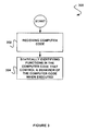
- FIG. 3 shows a method 300 for identifying control functions within computer code, in accordance with one embodiment.
- the method 300 may be implemented in the context of the architecture and environment of FIGS. 1 and/or 2 . Of course, however, the method 300 may be carried out in any desired environment.
- the computer code may include any computer code representative of, at least in part, a plurality of functions.
- the computer code may include binary computer code (e.g. computer code capable of being disassembled), uncompiled source code, an application, and/or any other type of computer code that is capable, at some point, of being read and/or executed by a computer.
- the computer code may be capable of being uncompressed, compiled, packed, etc.
- the computer code may be read and/or executed by any of the devices and/or component thereof described above with respect to FIGS. 1 and/or 2 .
- functions in the computer code that control a behavior of the computer code when executed are then statically identified, as shown in operation 304 .
- static identification may refer to any identification of the aforementioned functions that does not necessarily require execution of the computer code.
- the identification of operation 304 may take place without execution of the computer code.
- the identification of operation 304 may optionally further take place during emulation of the computer code (but it is not required). In still another embodiment, the identification of operation 304 may optionally further take place during execution of the computer code (but it is not required).
- the above functions may include any functionality capable of performing a task (or may take any form, for that matter, capable of controlling a behavior of the computer code, etc.).
- the functions may include commands and/or operations.
- the functions may each optionally return a value (the relevancy of which will be set forth hereinafter in greater detail during description of other embodiments, etc).
- the functions may be represented by computer code segments within the computer code.
- the above functions may be identified by tracing a call flow of the computer code. For instance, a function may be identified by matching a return instruction to an associated call instruction.
- the functions may be identified utilizing any desired method capable of identifying functions within computer code.
- the functions may control the behavior of the computer code in any particular way. Just by way of example, this may be accomplished by calling other functions, writing to memory, and/or by performing and/or initiating any other tasks within the computer code. Specifically, in one optional embodiment, the functions may control the behavior of the computer code by directly affecting the functionality of the computer code. Thus, in some embodiments, functions relevant to the functionality of the computer code may be identified.
- the functions in the computer code that control a behavior of the computer code may be identified according to a complexity threshold. For instance, functions within the computer code may be assigned a weight according to at least one property associated with each function. Examples of such property(s) will be described in further detail with respect to FIG. 4 . In this way, a subset of functions within the computer code that exceed a complexity threshold may be identified as functions that control a behavior of the computer code.
- identifying the functions may also include extracting the functions from the computer code.
- such functions may be extracted from the computer code utilizing a disassembler.
- the functions may be extracted by searching through computer code for known prologue/epilogue sequences, and/or cross references.
- the functions may be extracted from the computer code in any desired manner. In this way, functions that control a behavior of computer code may be identified.
- FIG. 4 shows a method 400 for constructing a control function tree from computer code, in accordance with another embodiment.
- the method 400 may be implemented in the context of the architecture and environment of FIGS. 1-3 . Of course, however, the method 400 may be carried out in any desired environment. It should also be noted that the aforementioned definitions may apply during the present description.
- Each function may include any function that resides within computer code.
- the functions may include the identified functions described above with respect to FIG. 3 .
- such functions may include a subset of functions within computer code that control the behavior of the computer code.
- each function may then be calculated based on a value of at least one property associated with each function. Furthermore, the complexity may also be based on a number of instances of the at least one property associated with the function. Table 1 illustrates examples of properties that may be utilized in calculating a complexity of a function. Of course, the complexity of each function may be calculated in any desired manner.
- Data Dependent Far call e.g. call on a value from a data section; generally Calls a call to an API comes under this category
- Outgoing Edges Calls to other functions; the greater number of calls to (Option: Minus Near various functions, the more active the function Jumps)
- Number of APIs used Memory Writes Signifies write access (e.g. number of times data/code section is written); it can cover simple instructions such as instructions including an “OR” command, or complex instructions with self modifying code
- Data Dependent Far jumps e.g. jump to a value from a data section).
- Jumps Incoming Edges Represents how many times a function or some part of a (Option: Minus Near function is called from another function(s); if the count is Jumps) high, this can be a library function or a frequently used function Near Jumps These are the jumps within a function; each jump creates a “label” Memory Reads Signifies the number of times a data section is read Data Offset Used Number of times an offset is used instead of a register or a direct value Total Number of Registers Used Register Used in Number of registered used in a memory reference (e.g. in Memory Reference instruction “lea edx, [esi + 1]” register esi is used in a memory reference) Stack Modification Number of stack modification instructions (e.g.
- a total complexity may be calculated based on a sum of property values associated with the function. Furthermore, each property value, as part of the sum, may be multiplied by the number of instances of the property associated with the function.
- Table 2 illustrates an exemplary equation that may be used to calculate a complexity of a function.
- the equation in Table 2 is set forth for illustrative purposes only. Any desired equation may be used for calculating the complexity of a function.
- each property may be associated with a specific value. Such values may be predefined or configurable.
- operations that are commonly used across all types of computer code e.g. memory read, memory erase, etc.
- operations that are commonly used across all types of computer code may have a lesser complexity value with respect to operations that are more likely to affect the functionality of the computer code (e.g. outgoing edge, etc.).
- a value associated with a commonly used function may be less than a value associated with a function called by a function within the computer code.
- the value of each property may be based on an importance of the property and/or the extent to which the property uniquely identifies the associated function.
- control functions are identified, as shown in operation 403 .
- the control functions may include a subset of the functions in the computer code with the highest total complexity value.
- the control functions may include the functions within the computer code whose operations have the greatest effect on the behavior (e.g. functionality, etc.) of the computer code.
- the control functions may include any number of functions.
- the control functions may be identified based on a total complexity value threshold, such that only functions with total complexity values greater than the threshold are identified as control functions.
- the control functions may be identified based on a minimum number of functions called, such that only functions containing up to a threshold number of nested functions are identified as control functions. It should be noted that it is not required that the nested functions be control functions.
- the aforementioned thresholds may be predefined or configurable. Of course, it should be noted that the control functions may be identified in any desired manner.
- a tree depth may optionally be controlled for each control function.
- the number of control functions that will be captured may also be configured via runtime parameters.
- control functions are then each utilized to construct a root level of a control tree data structure. See operation 404 .
- two control trees may be generated with each control function serving as a root to an associated control tree.
- decision 406 For each control tree, it is then determined whether another level of the control tree exists, as shown in decision 406 .
- the decision may be based on whether an associated control function contains any sub-functions (e.g. outgoing edges, etc.).
- sub-functions may include sub-functions that meet a threshold level of complexity, such as in the manner described above with respect to the process of identifying control functions.
- any functions with a degree of relationship to the control function may be added to the control tree at an associated level.
- a first level may include all functions that are directly called by the control functions (i.e. first degree of relationship)
- a second level may include all functions that are called by functions located in the first level (i.e. second degree of relationship)
- each control tree may be constructed based on a functional flow of the computer code. Examples of such control trees will be described in further detail with respect to FIG. 5 .
- control tree may be stored, as shown in operation 408 .
- the control tree may be stored in memory of the device containing the computer code.
- control tree may be stored anywhere capable of providing access to such control tree. In this way, functions that have the greatest affect on the behavior of the computer code may be identified and stored in a data structure along with any sub-functions thereof.
- any data structure may be utilized to store control functions and the sub-functions thereof, along with any other associated data.
- any data file may be used to store such information.
- an XML file may be used to store functional data associated with computer code, such as any of the calculated complexity values and/or control function identified in operations 402 and 403 .
- Table 3 illustrates one example of such an XML file.
- identified control functions, a complexity for each control function, and properties associated with each control function may be provided in an XML file associated with the computer code.
- XML file may be utilized for identifying functions that control a behavior of the computer code when executed.
- the XML file may be utilized for identifying the extent to which the identified functions control such behavior.
- FIG. 5 shows exemplary control function trees 500 and 550 , in accordance with yet another embodiment.
- the control function trees 500 and 550 may be implemented in the context of the architecture and environment of FIGS. 1-4 .
- the control function trees 500 and 550 may be used in any desired environment. It should also be noted that the aforementioned definitions may apply during the present description.
- the first control function tree 500 includes C 1 (control function 1 ) as a root.
- the second control function tree 550 includes C 2 (control function 2 ) as a root.
- each identified control function associated with computer code is included in a control tree at a root level.
- each sub-function of each identified control function is included in the control tree at an associated leaf/node level.
- each function path located in the control tree may represent a code path capable of existing within the computer code.
- C 1 calls functions F 0 , F 1 and F 2 .
- F 0 , F 1 and F 2 are placed in the first control tree 500 as nodes located in a first level.
- F 3 is called by F 0
- F 4 is called by F 1 , such that F 3 and F 4 are placed in the first control tree 500 as nodes located in a second level.
- C 2 is called by F 4 , and is therefore placed in the first control tree 500 as a node located in a third level.
- the second control function tree 550 is created in substantially the same manner as the first control function tree 500 .
- FIG. 6 shows a method 600 for comparing computer code, in accordance with still yet another embodiment.
- the method 600 may be implemented in the context of the architecture and environment of FIGS. 1-5 . Of course, however, the method 600 may be carried out in any desired environment. It should also be noted that the aforementioned definitions may apply during the present description.
- the function congruency table may include all functions within at least two separate sets of computer code.
- the function congruency table may include functions located within control trees, such as those described above with respect to FIGS. 4 and/or 5 .
- a control tree may overlap computer code with another control tree if they are from the same binary.
- the function congruency table does not necessarily contain the control tree itself, but rather it has all the functions from the binaries that were captured in all the control trees.
- Such function congruency table may include any data structure capable of recording a relationship between at least two function sets, each from separate sets of computer code.
- the function congruency table may be constructed by matching similar functions between computer codes and creating a map of such matched functions. For instance, properties associated with each function may be evaluated to determine which functions contain similar properties.
- FCV function congruency value
- the functions may be mapped according to complexity and similarity. For instance, if two functions from a first computer code have the same similarity to a function from a second computer code, the function from the first computer code with the greatest complexity may be mapped to the function from the second computer code. In this way, the function congruency value, and therefore the mapping, may be more accurate since the complexity required to create such similarity is greater.
- the mapping may be based on a function congruency threshold, such that functions with function congruency values meeting the threshold value may be mapped in the function congruency table.
- a function congruency threshold such that functions with function congruency values meeting the threshold value may be mapped in the function congruency table.
- control trees associated with the first code and the second code are each converted into vectors. Note operation 604 .
- Each vector represents the functional paths, and therefore code paths, capable of being taken by the control tree (and thus the associated control function).
- Each vector may be created by traversing an associated control tree from left to right and adding function nodes to the vector at each node.
- One example of such vectors will be described in further detail with respect to FIG. 7 .
- any data structure may be utilized that is capable of indicating a functional flow of computer code.
- the vectors are then compared, as shown in operation 606 .
- the vectors may be compared by evaluating each node of the vectors for matching sequences and/or matching functions.
- Table 4 illustrates a table of matching functions and exemplary vectors, such that the above described comparison may be further described in the context of one specific example.
- Vector 1 and Vector 2 have matching out-of-order functions, namely A 1 , B 1 , B 2 and A 2 .
- both Vector 1 and Vector 2 have matching in-order sequences, namely B 1 , C 1 , B 2 and C 2 .
- comparing the vectors in operation 606 may include identifying any and/or all of four types of matches, such as in-order sequences, in-order functions, out-of-order sequences, and/or out-of-order functions. Of course, any desired type of matches may be identified.
- Order may be determined according to the location of the functions in the vector being matched in association with the traversal of the vector from beginning to end. For example, if a sample Vector 1 contains sequence S 1 and S 2 which each match to a corresponding X 1 and X 2 in Vector 2 , but, in Vector 2 , X 1 and X 2 are in opposite order, such sequences may be considered out-of-order.
- the comparison of operation 606 may therefore allow similarities between two separate computer codes to be evaluated. As an option, order and sequences may be given greater weight than single function matches. In this way, similarities between controlling computer code behavior may be given the greatest weight in determining whether two separate computer codes are, in fact, similar, and potentially a part of the same class of computer code.
- each different match type may be assigned a value, such as in the manner described above.
- the values may be defined in any desired manner.
- by modifying the values of the different match types different types of similarities may be emphasized. For example, if all of the values are of the same value, the emphasis may be on computer code similarity irrespective of logic.
- a code similarity value may be output, as shown in operation 608 .
- the code similarity value may represent the amount of matching logic and/or code between two computer codes.
- the code similarity value may be calculated using a function congruency value from the function congruency table as a multiplier to the associated vector match values.
- the function congruency value may be utilized to normalize any match values, such that the code similarity value may represent the percentage of a total match between any functions and/or function sequences.
- the code similarity value may be calculated as a percentage.
- the total score for the matching in-order sequence value may be adjusted by 75% (e.g. assuming the matching in-order sequence value was 1, the total score for the matching sequence order may be equal to: 1 ⁇ 0.75+1 ⁇ 0.75).
- the code similarity value may then be calculated based on the fraction of the total value and a maximum possible value.
- the code similarity value could be calculated in any desired manner.
- the code similarity value may be stored in a table with the associated matching functions and/or sequences.
- a method for comparing computer codes utilizing the functions within the computer codes and their associated properties. Furthermore, the method is capable of making comparisons based on a percentage of similarities between the functions within the computer codes. Still yet, the method outputs matching results, where the matching results take into account such function congruency values, such that a match percentage reflects the actual similarity of the functions, and therefore the actual similarity of the computer code.
- computer code may be compared against computer code known to contain undesirable code (e.g. viruses, malware, Trojans, worms, spyware, adware, etc.), and such computer code may be identified as containing undesirable code based on a percentage match associated therewith. Specifically, the identification may be based on the functionality and/or behavior of the computer code. In this way, structural modifications made to the computer code may not necessarily interfere with determining whether the computer code contains undesirable code. Still yet, specific functions within the computer code may be matched to functions known to contain undesirable code, thus allowing a specific identification of the undesirable code within the computer code.
- undesirable code e.g. viruses, malware, Trojans, worms, spyware, adware, etc.
- this may be used to identify specific pieces of computer code, functions, and function sequences which represent a family or classification of undesirable code.
- this computer code can be used to identify heuristically that the code being evaluated is, in fact, undesirable and of a particular same classification/family.
- an identification that computer code contains undesirable code may be based on a threshold match percentage, such that only matches of a predetermined threshold may be considered to be actual matches.
- computer code may be compared against computer code of a known class, such that a class of the computer code may be determined.
- FIG. 7 shows an exemplary control function vector 700 , in accordance with another embodiment.
- the control function vector 700 may be implemented in the context of the architecture and environment of FIGS. 1-6 .
- the control function vector 700 may be used in any desired environment. It should also be noted that the aforementioned definitions may apply during the present description.
- control function vector 700 is a data structure that contains data associated with functions within computer code. Specifically, the control function vector 700 includes all functional flow paths capable of being taken by identified control functions. In the present example, the control function vector 700 may be associated with control function trees.
- control function vector 700 may correspond to the control function trees described above with respect to FIG. 5 .
- control function vector 700 may be associated with any data structure that includes information associated with functions in the computer code.
- the control function vector 700 contains a first element which is a first control function identified from the computer (i.e. a root of a first control function tree). Function flows are inserted into the control function vector 700 such that the control function vector 700 contains sub-functions of the first control function. As shown, a first function flow inserted into the control function vector 700 is C 1 -F 0 -F 3 . Such first function flow may correspond to a path located in the first control function tree. In substantially the same manner, subsequent function flows associated with the control function are inserted into the control vector function. The process then repeats for each control function.
- a first control function identified from the computer i.e. a root of a first control function tree.
- terrorism may be countered utilizing the aforementioned technology.
- cyber-terrorism is any “premeditated, politically motivated attack against information, computer systems, computer programs, and data which results in violence against non-combatant targets by sub-national groups or clandestine agents.”
- a cyber-terrorist attack is designed to cause physical violence or extreme financial harm.
- possible cyber-terrorist targets include the banking industry, military installations, power plants, air traffic control centers, and water systems.
- terrorism may be countered by classifying computer code and/or identifying computer code as including malware, etc., which may be used to combat cyber-terrorism.
Abstract
Description
| TABLE 1 | |
| Function Property | Explanation (if applicable) |
| Data Dependent | Far call (e.g. call on a value from a data section; generally |
| Calls | a call to an API comes under this category) |
| Outgoing Edges | Calls to other functions; the greater number of calls to |
| (Option: Minus Near | various functions, the more active the function |
| Jumps) | |
| Number of APIs used | |
| Memory Writes | Signifies write access (e.g. number of times data/code |
| section is written); it can cover simple instructions such as | |
| instructions including an “OR” command, or complex | |
| instructions with self modifying code | |
| Data Dependent | Far jumps (e.g. jump to a value from a data section). |
| Jumps | |
| Incoming Edges | Represents how many times a function or some part of a |
| (Option: Minus Near | function is called from another function(s); if the count is |
| Jumps) | high, this can be a library function or a frequently used |
| function | |
| Near Jumps | These are the jumps within a function; each jump creates a |
| “label” | |
| Memory Reads | Signifies the number of times a data section is read |
| Data Offset Used | Number of times an offset is used instead of a register or a |
| direct value | |
| Total Number of | |
| Registers Used | |
| Register Used in | Number of registered used in a memory reference (e.g. in |
| Memory Reference | instruction “lea edx, [esi + 1]” register esi is used in a |
| memory reference) | |
| Stack Modification | Number of stack modification instructions (e.g. push is +1 |
| Instructions | and pop is −1); If this number is >0, it signifies stack |
| modification | |
| Number of Byte | Number of a byte sequence, an assembly instruction, or a |
| Sequence, Assembly | set of instructions that can potentially identify a function |
| Instruction or Set of | |
| Instructions | |
| Number of Loops | A number of loops in the function |
| Number of Control | |
| Functions called in a | |
| Loop | |
| Number of Properties | A number of properties, such those described herein in |
| within a Loop | Table 1, identified within a loop of the function |
| Checksum | A checksum of the function |
| Size | A size of the function |
| TABLE 2 | ||
| Function Properties: P1, P2, P3, P2, P4 | ||
| Function Complexity: ValP1 + (ValP2*2) + ValP3 + ValP4 | ||
| TABLE 3 |
| <?xml version=“1.0” encoding=“Windows-1252” standalone=“yes” ?> |
| − <File MD5=“45 28 BC 37 65 BA 63 57 8D 9D 83 0E 8C 84 44 93”> |
| + <FunctionNode Id=“4013aa” Type=“Control”> |
| + <FunctionNode Id=“40135c” Type=“Default”> |
| + <FunctionNode Id=“401ca6” Type=“Default”> |
| + <FunctionNode Id=“401cc0” Type=“Default”> |
| − <FunctionNode Id=“401bba” Type=“Control”> |
| <Complexity>123</Complexity> |
| <Incoming>1</Incoming> |
| <Outgoing>2</Outgoing> |
| <API_Used>9</API_Used> |
| − <FunctionCallList> |
| <APIName>RtlInitUnicodeString</APIName> |
| <FunctionName>4012c4</FunctionName> |
| <APIName>IoDeleteSymbolicLink</APIName> |
| <APIName>IoDeleteDevice</APIName> |
| <FunctionName>401332</FunctionName> |
| <APTName>IoDeleteSymbolicLink</APIName> |
| <APIName>IoDeleteDevice</APIName> |
| </FunctionCallList> |
It should be noted that Table 3 is set forth for illustration only, and should not be construed as limiting in any manner.
| TABLE 4 | |||
| Computer Code 01 | Computer Code 02 | ||
| A1 | A2 | ||
| B1 | B2 | ||
| C1 | C2 | ||
| Unmatched functions: X1, Y1 | Unmatched functions: R2, S2 | ||
| where, | |||
| Unmatched functions = X1, Y1, R2, S2 | |||
| Vector1 = A1-B1-X1-Y1-B1- | |||
| Vector | |||
| 2 = B2-A2-R2-A2-S2-B2-C2-B2 | |||
Of course, such example is set forth only by way of illustration, and is not to be construed as limiting in any manner
Claims (19)
Priority Applications (1)
| Application Number | Priority Date | Filing Date | Title |
|---|---|---|---|
| US13/180,030 US8327439B2 (en) | 2006-05-10 | 2011-07-11 | System, method and computer program product for identifying functions in computer code that control a behavior thereof when executed |
Applications Claiming Priority (2)
| Application Number | Priority Date | Filing Date | Title |
|---|---|---|---|
| US11/432,648 US8001595B1 (en) | 2006-05-10 | 2006-05-10 | System, method and computer program product for identifying functions in computer code that control a behavior thereof when executed |
| US13/180,030 US8327439B2 (en) | 2006-05-10 | 2011-07-11 | System, method and computer program product for identifying functions in computer code that control a behavior thereof when executed |
Related Parent Applications (1)
| Application Number | Title | Priority Date | Filing Date |
|---|---|---|---|
| US11/432,648 Continuation US8001595B1 (en) | 2006-05-10 | 2006-05-10 | System, method and computer program product for identifying functions in computer code that control a behavior thereof when executed |
Publications (2)
| Publication Number | Publication Date |
|---|---|
| US20110271346A1 US20110271346A1 (en) | 2011-11-03 |
| US8327439B2 true US8327439B2 (en) | 2012-12-04 |
Family
ID=44358688
Family Applications (2)
| Application Number | Title | Priority Date | Filing Date |
|---|---|---|---|
| US11/432,648 Active 2030-02-13 US8001595B1 (en) | 2006-05-10 | 2006-05-10 | System, method and computer program product for identifying functions in computer code that control a behavior thereof when executed |
| US13/180,030 Active US8327439B2 (en) | 2006-05-10 | 2011-07-11 | System, method and computer program product for identifying functions in computer code that control a behavior thereof when executed |
Family Applications Before (1)
| Application Number | Title | Priority Date | Filing Date |
|---|---|---|---|
| US11/432,648 Active 2030-02-13 US8001595B1 (en) | 2006-05-10 | 2006-05-10 | System, method and computer program product for identifying functions in computer code that control a behavior thereof when executed |
Country Status (1)
| Country | Link |
|---|---|
| US (2) | US8001595B1 (en) |
Cited By (2)
| Publication number | Priority date | Publication date | Assignee | Title |
|---|---|---|---|---|
| US9591022B2 (en) | 2014-12-17 | 2017-03-07 | The Boeing Company | Computer defenses and counterattacks |
| US10938742B1 (en) | 2020-01-31 | 2021-03-02 | Bank Of America Corporation | Multiplexed resource allocation architecture |
Families Citing this family (8)
| Publication number | Priority date | Publication date | Assignee | Title |
|---|---|---|---|---|
| US8001595B1 (en) * | 2006-05-10 | 2011-08-16 | Mcafee, Inc. | System, method and computer program product for identifying functions in computer code that control a behavior thereof when executed |
| US8769702B2 (en) * | 2008-04-16 | 2014-07-01 | Micosoft Corporation | Application reputation service |
| US8621625B1 (en) * | 2008-12-23 | 2013-12-31 | Symantec Corporation | Methods and systems for detecting infected files |
| US8370934B2 (en) | 2009-06-25 | 2013-02-05 | Check Point Software Technologies Ltd. | Methods for detecting malicious programs using a multilayered heuristics approach |
| CN102819698B (en) * | 2011-12-27 | 2015-05-20 | 腾讯科技(深圳)有限公司 | Method and device for detecting malicious code in webpage |
| WO2015101096A1 (en) * | 2013-12-30 | 2015-07-09 | 北京奇虎科技有限公司 | Method and device for detecting malicious code in smart terminal |
| US9396044B2 (en) * | 2014-04-25 | 2016-07-19 | Sony Corporation | Memory efficient thread-level speculation |
| CN104849648B (en) * | 2015-05-26 | 2017-11-07 | 大连理工大学 | A kind of test vector generating method for improving wooden horse activity |
Citations (16)
| Publication number | Priority date | Publication date | Assignee | Title |
|---|---|---|---|---|
| US5987610A (en) | 1998-02-12 | 1999-11-16 | Ameritech Corporation | Computer virus screening methods and systems |
| US6073142A (en) | 1997-06-23 | 2000-06-06 | Park City Group | Automated post office based rule analysis of e-mail messages and other data objects for controlled distribution in network environments |
| US6119236A (en) | 1996-10-07 | 2000-09-12 | Shipley; Peter M. | Intelligent network security device and method |
| US6460050B1 (en) | 1999-12-22 | 2002-10-01 | Mark Raymond Pace | Distributed content identification system |
| US20030101381A1 (en) | 2001-11-29 | 2003-05-29 | Nikolay Mateev | System and method for virus checking software |
| US20040111708A1 (en) | 2002-09-09 | 2004-06-10 | The Regents Of The University Of California | Method and apparatus for identifying similar regions of a program's execution |
| US20050060295A1 (en) | 2003-09-12 | 2005-03-17 | Sensory Networks, Inc. | Statistical classification of high-speed network data through content inspection |
| US6873935B2 (en) | 2003-03-03 | 2005-03-29 | Microsoft Corporation | System and method for statically checking source code |
| US20050108562A1 (en) | 2003-06-18 | 2005-05-19 | Khazan Roger I. | Technique for detecting executable malicious code using a combination of static and dynamic analyses |
| US20050198649A1 (en) | 2004-03-02 | 2005-09-08 | Alex Zakonov | Software application action monitoring |
| US6980992B1 (en) | 2001-07-26 | 2005-12-27 | Mcafee, Inc. | Tree pattern system and method for multiple virus signature recognition |
| US20060230453A1 (en) * | 2005-03-30 | 2006-10-12 | Flynn Lori A | Method of polymorphic detection |
| US20070083933A1 (en) | 2005-10-07 | 2007-04-12 | Microsoft Corporation | Detection of security vulnerabilities in computer programs |
| US20070113282A1 (en) | 2005-11-17 | 2007-05-17 | Ross Robert F | Systems and methods for detecting and disabling malicious script code |
| US7506155B1 (en) | 2000-06-22 | 2009-03-17 | Gatekeeper Llc | E-mail virus protection system and method |
| US8001595B1 (en) * | 2006-05-10 | 2011-08-16 | Mcafee, Inc. | System, method and computer program product for identifying functions in computer code that control a behavior thereof when executed |
-
2006
- 2006-05-10 US US11/432,648 patent/US8001595B1/en active Active
-
2011
- 2011-07-11 US US13/180,030 patent/US8327439B2/en active Active
Patent Citations (16)
| Publication number | Priority date | Publication date | Assignee | Title |
|---|---|---|---|---|
| US6119236A (en) | 1996-10-07 | 2000-09-12 | Shipley; Peter M. | Intelligent network security device and method |
| US6073142A (en) | 1997-06-23 | 2000-06-06 | Park City Group | Automated post office based rule analysis of e-mail messages and other data objects for controlled distribution in network environments |
| US5987610A (en) | 1998-02-12 | 1999-11-16 | Ameritech Corporation | Computer virus screening methods and systems |
| US6460050B1 (en) | 1999-12-22 | 2002-10-01 | Mark Raymond Pace | Distributed content identification system |
| US7506155B1 (en) | 2000-06-22 | 2009-03-17 | Gatekeeper Llc | E-mail virus protection system and method |
| US6980992B1 (en) | 2001-07-26 | 2005-12-27 | Mcafee, Inc. | Tree pattern system and method for multiple virus signature recognition |
| US20030101381A1 (en) | 2001-11-29 | 2003-05-29 | Nikolay Mateev | System and method for virus checking software |
| US20040111708A1 (en) | 2002-09-09 | 2004-06-10 | The Regents Of The University Of California | Method and apparatus for identifying similar regions of a program's execution |
| US6873935B2 (en) | 2003-03-03 | 2005-03-29 | Microsoft Corporation | System and method for statically checking source code |
| US20050108562A1 (en) | 2003-06-18 | 2005-05-19 | Khazan Roger I. | Technique for detecting executable malicious code using a combination of static and dynamic analyses |
| US20050060295A1 (en) | 2003-09-12 | 2005-03-17 | Sensory Networks, Inc. | Statistical classification of high-speed network data through content inspection |
| US20050198649A1 (en) | 2004-03-02 | 2005-09-08 | Alex Zakonov | Software application action monitoring |
| US20060230453A1 (en) * | 2005-03-30 | 2006-10-12 | Flynn Lori A | Method of polymorphic detection |
| US20070083933A1 (en) | 2005-10-07 | 2007-04-12 | Microsoft Corporation | Detection of security vulnerabilities in computer programs |
| US20070113282A1 (en) | 2005-11-17 | 2007-05-17 | Ross Robert F | Systems and methods for detecting and disabling malicious script code |
| US8001595B1 (en) * | 2006-05-10 | 2011-08-16 | Mcafee, Inc. | System, method and computer program product for identifying functions in computer code that control a behavior thereof when executed |
Non-Patent Citations (4)
| Title |
|---|
| Carrera, Ero et al., "Digital Genome Mapping-Advanced Binary Malware Analysis," Virus Bulletin Conference, Sep. 2004 (11 pages). |
| Flake, Halvar, "Automated Reverse Engineering," Black Hat Windows 2004 (79 pages). |
| Sabin, Todd, "BindView Razor Team," Symantec, http://www.bindview.com/Services/Razor/Papers/2004/comparing-binaries.cfm (22 pages). |
| Xu, et al., Safety Checking of Machine Code, Computer Sciences Department, University of Wisconsin, copyright 2000 (13 pages). |
Cited By (3)
| Publication number | Priority date | Publication date | Assignee | Title |
|---|---|---|---|---|
| US9591022B2 (en) | 2014-12-17 | 2017-03-07 | The Boeing Company | Computer defenses and counterattacks |
| US10938742B1 (en) | 2020-01-31 | 2021-03-02 | Bank Of America Corporation | Multiplexed resource allocation architecture |
| US11171881B2 (en) | 2020-01-31 | 2021-11-09 | Bank Of America Corporation | Multiplexed resource allocation architecture |
Also Published As
| Publication number | Publication date |
|---|---|
| US20110271346A1 (en) | 2011-11-03 |
| US8001595B1 (en) | 2011-08-16 |
Similar Documents
| Publication | Publication Date | Title |
|---|---|---|
| US8327439B2 (en) | System, method and computer program product for identifying functions in computer code that control a behavior thereof when executed | |
| US11188650B2 (en) | Detection of malware using feature hashing | |
| US9680847B2 (en) | Structural recognition of malicious code patterns | |
| US20040205411A1 (en) | Method of detecting malicious scripts using code insertion technique | |
| US7640587B2 (en) | Source code repair method for malicious code detection | |
| US7877802B2 (en) | System and method for proactive computer virus protection | |
| TW538376B (en) | Analytical virtual machine | |
| US20170372068A1 (en) | Method to identify known compilers functions, libraries and objects inside files and data items containing an executable code | |
| US11882134B2 (en) | Stateful rule generation for behavior based threat detection | |
| US9798981B2 (en) | Determining malware based on signal tokens | |
| US10242190B2 (en) | System and method for detection of malicious code by iterative emulation of microcode | |
| US20130117853A1 (en) | Methods for detecting malicious programs using a multilayered heuristics approach | |
| US7739100B1 (en) | Emulation system, method and computer program product for malware detection by back-stepping in program code | |
| US11379581B2 (en) | System and method for detection of malicious files | |
| US8209757B1 (en) | Direct call into system DLL detection system and method | |
| US8332941B2 (en) | Exploit nonspecific host intrusion prevention/detection methods and systems and smart filters therefor | |
| US7389538B2 (en) | Static code image modeling and recognition | |
| US7904955B1 (en) | Method and apparatus for detecting shellcode | |
| CN103679027A (en) | Searching and killing method and device for kernel level malware | |
| Shan et al. | Mobile agent protection with self-modifying code | |
| EP3798885B1 (en) | System and method for detection of malicious files | |
| US7774843B1 (en) | System, method and computer program product for preventing the execution of unwanted code | |
| US9881155B2 (en) | System and method for automatic use-after-free exploit detection | |
| CN111752570A (en) | Compiling method, device, terminal and computer readable storage medium | |
| Nix | Applying deep learning techniques to the analysis of Android APKs |
Legal Events
| Date | Code | Title | Description |
|---|---|---|---|
| STCF | Information on status: patent grant |
Free format text: PATENTED CASE |
|
| FPAY | Fee payment |
Year of fee payment: 4 |
|
| AS | Assignment |
Owner name: MCAFEE, LLC, CALIFORNIA Free format text: CHANGE OF NAME AND ENTITY CONVERSION;ASSIGNOR:MCAFEE, INC.;REEL/FRAME:043665/0918 Effective date: 20161220 |
|
| AS | Assignment |
Owner name: MORGAN STANLEY SENIOR FUNDING, INC., MARYLAND Free format text: SECURITY INTEREST;ASSIGNOR:MCAFEE, LLC;REEL/FRAME:045056/0676 Effective date: 20170929 Owner name: JPMORGAN CHASE BANK, N.A., NEW YORK Free format text: SECURITY INTEREST;ASSIGNOR:MCAFEE, LLC;REEL/FRAME:045055/0786 Effective date: 20170929 |
|
| MAFP | Maintenance fee payment |
Free format text: PAYMENT OF MAINTENANCE FEE, 8TH YEAR, LARGE ENTITY (ORIGINAL EVENT CODE: M1552); ENTITY STATUS OF PATENT OWNER: LARGE ENTITY Year of fee payment: 8 |
|
| AS | Assignment |
Owner name: MORGAN STANLEY SENIOR FUNDING, INC., MARYLAND Free format text: CORRECTIVE ASSIGNMENT TO CORRECT THE REMOVE PATENT 6336186 PREVIOUSLY RECORDED ON REEL 045056 FRAME 0676. ASSIGNOR(S) HEREBY CONFIRMS THE SECURITY INTEREST;ASSIGNOR:MCAFEE, LLC;REEL/FRAME:054206/0593 Effective date: 20170929 Owner name: JPMORGAN CHASE BANK, N.A., NEW YORK Free format text: CORRECTIVE ASSIGNMENT TO CORRECT THE REMOVE PATENT 6336186 PREVIOUSLY RECORDED ON REEL 045055 FRAME 786. ASSIGNOR(S) HEREBY CONFIRMS THE SECURITY INTEREST;ASSIGNOR:MCAFEE, LLC;REEL/FRAME:055854/0047 Effective date: 20170929 |
|
| AS | Assignment |
Owner name: MCAFEE, LLC, CALIFORNIA Free format text: RELEASE OF INTELLECTUAL PROPERTY COLLATERAL - REEL/FRAME 045055/0786;ASSIGNOR:JPMORGAN CHASE BANK, N.A., AS COLLATERAL AGENT;REEL/FRAME:054238/0001 Effective date: 20201026 |
|
| AS | Assignment |
Owner name: MCAFEE, LLC, CALIFORNIA Free format text: RELEASE OF INTELLECTUAL PROPERTY COLLATERAL - REEL/FRAME 045056/0676;ASSIGNOR:MORGAN STANLEY SENIOR FUNDING, INC., AS COLLATERAL AGENT;REEL/FRAME:059354/0213 Effective date: 20220301 |
|
| AS | Assignment |
Owner name: JPMORGAN CHASE BANK, N.A., AS ADMINISTRATIVE AGENT AND COLLATERAL AGENT, NEW YORK Free format text: SECURITY INTEREST;ASSIGNOR:MCAFEE, LLC;REEL/FRAME:059354/0335 Effective date: 20220301 |
|
| AS | Assignment |
Owner name: JPMORGAN CHASE BANK, N.A., AS ADMINISTRATIVE AGENT, NEW YORK Free format text: CORRECTIVE ASSIGNMENT TO CORRECT THE THE PATENT TITLES AND REMOVE DUPLICATES IN THE SCHEDULE PREVIOUSLY RECORDED AT REEL: 059354 FRAME: 0335. ASSIGNOR(S) HEREBY CONFIRMS THE ASSIGNMENT;ASSIGNOR:MCAFEE, LLC;REEL/FRAME:060792/0307 Effective date: 20220301 |