US8092864B2 - Mandrel and method for coating open-cell implantable endovascular structures - Google Patents
Mandrel and method for coating open-cell implantable endovascular structures Download PDFInfo
- Publication number
- US8092864B2 US8092864B2 US12/199,189 US19918908A US8092864B2 US 8092864 B2 US8092864 B2 US 8092864B2 US 19918908 A US19918908 A US 19918908A US 8092864 B2 US8092864 B2 US 8092864B2
- Authority
- US
- United States
- Prior art keywords
- medical device
- axial member
- coating
- tubular medical
- diameter
- Prior art date
- Legal status (The legal status is an assumption and is not a legal conclusion. Google has not performed a legal analysis and makes no representation as to the accuracy of the status listed.)
- Expired - Fee Related, expires
Links
- 238000000576 coating method Methods 0.000 title claims abstract description 211
- 239000011248 coating agent Substances 0.000 title claims abstract description 193
- 238000000034 method Methods 0.000 title claims abstract description 63
- 239000007921 spray Substances 0.000 claims abstract description 70
- 239000003814 drug Substances 0.000 claims abstract description 49
- 229940124597 therapeutic agent Drugs 0.000 claims abstract description 48
- 238000005507 spraying Methods 0.000 claims abstract description 29
- 239000002904 solvent Substances 0.000 claims abstract description 26
- 230000002792 vascular Effects 0.000 claims description 66
- 229930012538 Paclitaxel Natural products 0.000 claims description 33
- 229960001592 paclitaxel Drugs 0.000 claims description 33
- RCINICONZNJXQF-MZXODVADSA-N taxol Chemical compound O([C@@H]1[C@@]2(C[C@@H](C(C)=C(C2(C)C)[C@H](C([C@]2(C)[C@@H](O)C[C@H]3OC[C@]3([C@H]21)OC(C)=O)=O)OC(=O)C)OC(=O)[C@H](O)[C@@H](NC(=O)C=1C=CC=CC=1)C=1C=CC=CC=1)O)C(=O)C1=CC=CC=C1 RCINICONZNJXQF-MZXODVADSA-N 0.000 claims description 33
- 230000008878 coupling Effects 0.000 claims description 14
- 238000010168 coupling process Methods 0.000 claims description 14
- 238000005859 coupling reaction Methods 0.000 claims description 14
- 229920000642 polymer Polymers 0.000 claims description 7
- 239000003960 organic solvent Substances 0.000 claims 3
- 238000001704 evaporation Methods 0.000 claims 1
- YMWUJEATGCHHMB-UHFFFAOYSA-N Dichloromethane Chemical compound ClCCl YMWUJEATGCHHMB-UHFFFAOYSA-N 0.000 description 39
- OKKJLVBELUTLKV-UHFFFAOYSA-N Methanol Chemical compound OC OKKJLVBELUTLKV-UHFFFAOYSA-N 0.000 description 30
- 230000008569 process Effects 0.000 description 20
- 229920000747 poly(lactic acid) Polymers 0.000 description 16
- 239000004626 polylactic acid Substances 0.000 description 15
- LFQSCWFLJHTTHZ-UHFFFAOYSA-N Ethanol Chemical compound CCO LFQSCWFLJHTTHZ-UHFFFAOYSA-N 0.000 description 12
- 239000000463 material Substances 0.000 description 11
- IJGRMHOSHXDMSA-UHFFFAOYSA-N Atomic nitrogen Chemical compound N#N IJGRMHOSHXDMSA-UHFFFAOYSA-N 0.000 description 10
- 238000004110 electrostatic spray deposition (ESD) technique Methods 0.000 description 10
- 229920001971 elastomer Polymers 0.000 description 9
- 239000000806 elastomer Substances 0.000 description 9
- 239000000203 mixture Substances 0.000 description 9
- 239000007788 liquid Substances 0.000 description 7
- 239000002356 single layer Substances 0.000 description 7
- 210000004027 cell Anatomy 0.000 description 5
- 230000007547 defect Effects 0.000 description 5
- 238000000151 deposition Methods 0.000 description 5
- 239000010410 layer Substances 0.000 description 5
- 229910052757 nitrogen Inorganic materials 0.000 description 5
- JVTAAEKCZFNVCJ-REOHCLBHSA-N L-lactic acid Chemical compound C[C@H](O)C(O)=O JVTAAEKCZFNVCJ-REOHCLBHSA-N 0.000 description 4
- 230000008021 deposition Effects 0.000 description 4
- 238000007667 floating Methods 0.000 description 4
- AEMRFAOFKBGASW-UHFFFAOYSA-N Glycolic acid Polymers OCC(O)=O AEMRFAOFKBGASW-UHFFFAOYSA-N 0.000 description 3
- 239000000853 adhesive Substances 0.000 description 3
- 230000001070 adhesive effect Effects 0.000 description 3
- QVGXLLKOCUKJST-UHFFFAOYSA-N atomic oxygen Chemical compound [O] QVGXLLKOCUKJST-UHFFFAOYSA-N 0.000 description 3
- 239000011247 coating layer Substances 0.000 description 3
- 238000007590 electrostatic spraying Methods 0.000 description 3
- 239000012530 fluid Substances 0.000 description 3
- 239000007789 gas Substances 0.000 description 3
- 239000001301 oxygen Substances 0.000 description 3
- 229910052760 oxygen Inorganic materials 0.000 description 3
- 238000010926 purge Methods 0.000 description 3
- 238000005476 soldering Methods 0.000 description 3
- 229920000954 Polyglycolide Polymers 0.000 description 2
- 102000013530 TOR Serine-Threonine Kinases Human genes 0.000 description 2
- 108010065917 TOR Serine-Threonine Kinases Proteins 0.000 description 2
- 238000000889 atomisation Methods 0.000 description 2
- 239000003795 chemical substances by application Substances 0.000 description 2
- 239000013078 crystal Substances 0.000 description 2
- 201000010099 disease Diseases 0.000 description 2
- 208000037265 diseases, disorders, signs and symptoms Diseases 0.000 description 2
- 238000012377 drug delivery Methods 0.000 description 2
- 230000000694 effects Effects 0.000 description 2
- 230000005284 excitation Effects 0.000 description 2
- 239000003517 fume Substances 0.000 description 2
- 239000002184 metal Substances 0.000 description 2
- 238000012986 modification Methods 0.000 description 2
- 230000004048 modification Effects 0.000 description 2
- HLXZNVUGXRDIFK-UHFFFAOYSA-N nickel titanium Chemical compound [Ti].[Ti].[Ti].[Ti].[Ti].[Ti].[Ti].[Ti].[Ti].[Ti].[Ti].[Ni].[Ni].[Ni].[Ni].[Ni].[Ni].[Ni].[Ni].[Ni].[Ni].[Ni].[Ni].[Ni].[Ni] HLXZNVUGXRDIFK-UHFFFAOYSA-N 0.000 description 2
- 229910001000 nickel titanium Inorganic materials 0.000 description 2
- 239000005014 poly(hydroxyalkanoate) Substances 0.000 description 2
- 229920000903 polyhydroxyalkanoate Polymers 0.000 description 2
- 208000037803 restenosis Diseases 0.000 description 2
- 239000011877 solvent mixture Substances 0.000 description 2
- 238000000527 sonication Methods 0.000 description 2
- 238000009718 spray deposition Methods 0.000 description 2
- 229910001220 stainless steel Inorganic materials 0.000 description 2
- 239000010935 stainless steel Substances 0.000 description 2
- XLYOFNOQVPJJNP-UHFFFAOYSA-N water Substances O XLYOFNOQVPJJNP-UHFFFAOYSA-N 0.000 description 2
- LEBVLXFERQHONN-UHFFFAOYSA-N 1-butyl-N-(2,6-dimethylphenyl)piperidine-2-carboxamide Chemical compound CCCCN1CCCCC1C(=O)NC1=C(C)C=CC=C1C LEBVLXFERQHONN-UHFFFAOYSA-N 0.000 description 1
- HBAQYPYDRFILMT-UHFFFAOYSA-N 8-[3-(1-cyclopropylpyrazol-4-yl)-1H-pyrazolo[4,3-d]pyrimidin-5-yl]-3-methyl-3,8-diazabicyclo[3.2.1]octan-2-one Chemical class C1(CC1)N1N=CC(=C1)C1=NNC2=C1N=C(N=C2)N1C2C(N(CC1CC2)C)=O HBAQYPYDRFILMT-UHFFFAOYSA-N 0.000 description 1
- 241000282346 Meles meles Species 0.000 description 1
- 102000029749 Microtubule Human genes 0.000 description 1
- 108091022875 Microtubule Proteins 0.000 description 1
- 239000004677 Nylon Substances 0.000 description 1
- 241001193704 Orbus Species 0.000 description 1
- 208000034530 PLAA-associated neurodevelopmental disease Diseases 0.000 description 1
- 208000031481 Pathologic Constriction Diseases 0.000 description 1
- 239000013543 active substance Substances 0.000 description 1
- 230000002411 adverse Effects 0.000 description 1
- 229940061720 alpha hydroxy acid Drugs 0.000 description 1
- 150000001280 alpha hydroxy acids Chemical class 0.000 description 1
- 230000004075 alteration Effects 0.000 description 1
- 230000003321 amplification Effects 0.000 description 1
- 238000002399 angioplasty Methods 0.000 description 1
- 230000000692 anti-sense effect Effects 0.000 description 1
- 239000012298 atmosphere Substances 0.000 description 1
- 230000000975 bioactive effect Effects 0.000 description 1
- 229920002988 biodegradable polymer Polymers 0.000 description 1
- 239000004621 biodegradable polymer Substances 0.000 description 1
- 238000006065 biodegradation reaction Methods 0.000 description 1
- 210000004204 blood vessel Anatomy 0.000 description 1
- 229960003150 bupivacaine Drugs 0.000 description 1
- 239000008199 coating composition Substances 0.000 description 1
- 230000000295 complement effect Effects 0.000 description 1
- 150000001875 compounds Chemical class 0.000 description 1
- 230000006835 compression Effects 0.000 description 1
- 238000007906 compression Methods 0.000 description 1
- 238000013270 controlled release Methods 0.000 description 1
- 230000010339 dilation Effects 0.000 description 1
- 238000007598 dipping method Methods 0.000 description 1
- UODXSCCNACAPCE-UHFFFAOYSA-N draft:flumetramide Chemical compound C1=CC(C(F)(F)F)=CC=C1C1OCC(=O)NC1 UODXSCCNACAPCE-UHFFFAOYSA-N 0.000 description 1
- 229940079593 drug Drugs 0.000 description 1
- 238000001647 drug administration Methods 0.000 description 1
- 238000001035 drying Methods 0.000 description 1
- 238000004070 electrodeposition Methods 0.000 description 1
- 238000009503 electrostatic coating Methods 0.000 description 1
- 238000005516 engineering process Methods 0.000 description 1
- 239000000835 fiber Substances 0.000 description 1
- 230000002496 gastric effect Effects 0.000 description 1
- 208000019622 heart disease Diseases 0.000 description 1
- 239000000017 hydrogel Substances 0.000 description 1
- 238000002513 implantation Methods 0.000 description 1
- 239000003112 inhibitor Substances 0.000 description 1
- 238000011068 loading method Methods 0.000 description 1
- 230000007774 longterm Effects 0.000 description 1
- 230000007246 mechanism Effects 0.000 description 1
- 210000004688 microtubule Anatomy 0.000 description 1
- 239000003595 mist Substances 0.000 description 1
- 238000003199 nucleic acid amplification method Methods 0.000 description 1
- 229920001778 nylon Polymers 0.000 description 1
- XIMBESZRBTVIOD-UHFFFAOYSA-N piperidine-2-carboxamide Chemical compound NC(=O)C1CCCCN1 XIMBESZRBTVIOD-UHFFFAOYSA-N 0.000 description 1
- -1 poly(glycerol-sebacate) Polymers 0.000 description 1
- 229920002791 poly-4-hydroxybutyrate Polymers 0.000 description 1
- 239000004633 polyglycolic acid Substances 0.000 description 1
- 238000006116 polymerization reaction Methods 0.000 description 1
- 229920001296 polysiloxane Polymers 0.000 description 1
- 239000002243 precursor Substances 0.000 description 1
- 108090000765 processed proteins & peptides Proteins 0.000 description 1
- 230000001737 promoting effect Effects 0.000 description 1
- 238000007665 sagging Methods 0.000 description 1
- 239000007787 solid Substances 0.000 description 1
- 239000003381 stabilizer Substances 0.000 description 1
- 208000037804 stenosis Diseases 0.000 description 1
- 230000036262 stenosis Effects 0.000 description 1
- 239000000758 substrate Substances 0.000 description 1
- 238000013268 sustained release Methods 0.000 description 1
- 239000012730 sustained-release form Substances 0.000 description 1
- 238000007910 systemic administration Methods 0.000 description 1
- 230000009885 systemic effect Effects 0.000 description 1
- 230000001225 therapeutic effect Effects 0.000 description 1
- 230000007704 transition Effects 0.000 description 1
- 238000002604 ultrasonography Methods 0.000 description 1
- 238000007740 vapor deposition Methods 0.000 description 1
- 238000003466 welding Methods 0.000 description 1
Images


Classifications
-
- B—PERFORMING OPERATIONS; TRANSPORTING
- B05—SPRAYING OR ATOMISING IN GENERAL; APPLYING FLUENT MATERIALS TO SURFACES, IN GENERAL
- B05D—PROCESSES FOR APPLYING FLUENT MATERIALS TO SURFACES, IN GENERAL
- B05D1/00—Processes for applying liquids or other fluent materials
- B05D1/02—Processes for applying liquids or other fluent materials performed by spraying
-
- A—HUMAN NECESSITIES
- A61—MEDICAL OR VETERINARY SCIENCE; HYGIENE
- A61F—FILTERS IMPLANTABLE INTO BLOOD VESSELS; PROSTHESES; DEVICES PROVIDING PATENCY TO, OR PREVENTING COLLAPSING OF, TUBULAR STRUCTURES OF THE BODY, e.g. STENTS; ORTHOPAEDIC, NURSING OR CONTRACEPTIVE DEVICES; FOMENTATION; TREATMENT OR PROTECTION OF EYES OR EARS; BANDAGES, DRESSINGS OR ABSORBENT PADS; FIRST-AID KITS
- A61F2/00—Filters implantable into blood vessels; Prostheses, i.e. artificial substitutes or replacements for parts of the body; Appliances for connecting them with the body; Devices providing patency to, or preventing collapsing of, tubular structures of the body, e.g. stents
- A61F2/82—Devices providing patency to, or preventing collapsing of, tubular structures of the body, e.g. stents
- A61F2/86—Stents in a form characterised by the wire-like elements; Stents in the form characterised by a net-like or mesh-like structure
- A61F2/88—Stents in a form characterised by the wire-like elements; Stents in the form characterised by a net-like or mesh-like structure the wire-like elements formed as helical or spiral coils
-
- A—HUMAN NECESSITIES
- A61—MEDICAL OR VETERINARY SCIENCE; HYGIENE
- A61L—METHODS OR APPARATUS FOR STERILISING MATERIALS OR OBJECTS IN GENERAL; DISINFECTION, STERILISATION OR DEODORISATION OF AIR; CHEMICAL ASPECTS OF BANDAGES, DRESSINGS, ABSORBENT PADS OR SURGICAL ARTICLES; MATERIALS FOR BANDAGES, DRESSINGS, ABSORBENT PADS OR SURGICAL ARTICLES
- A61L31/00—Materials for other surgical articles, e.g. stents, stent-grafts, shunts, surgical drapes, guide wires, materials for adhesion prevention, occluding devices, surgical gloves, tissue fixation devices
- A61L31/08—Materials for coatings
- A61L31/10—Macromolecular materials
-
- A—HUMAN NECESSITIES
- A61—MEDICAL OR VETERINARY SCIENCE; HYGIENE
- A61L—METHODS OR APPARATUS FOR STERILISING MATERIALS OR OBJECTS IN GENERAL; DISINFECTION, STERILISATION OR DEODORISATION OF AIR; CHEMICAL ASPECTS OF BANDAGES, DRESSINGS, ABSORBENT PADS OR SURGICAL ARTICLES; MATERIALS FOR BANDAGES, DRESSINGS, ABSORBENT PADS OR SURGICAL ARTICLES
- A61L31/00—Materials for other surgical articles, e.g. stents, stent-grafts, shunts, surgical drapes, guide wires, materials for adhesion prevention, occluding devices, surgical gloves, tissue fixation devices
- A61L31/14—Materials characterised by their function or physical properties, e.g. injectable or lubricating compositions, shape-memory materials, surface modified materials
- A61L31/16—Biologically active materials, e.g. therapeutic substances
-
- A—HUMAN NECESSITIES
- A61—MEDICAL OR VETERINARY SCIENCE; HYGIENE
- A61F—FILTERS IMPLANTABLE INTO BLOOD VESSELS; PROSTHESES; DEVICES PROVIDING PATENCY TO, OR PREVENTING COLLAPSING OF, TUBULAR STRUCTURES OF THE BODY, e.g. STENTS; ORTHOPAEDIC, NURSING OR CONTRACEPTIVE DEVICES; FOMENTATION; TREATMENT OR PROTECTION OF EYES OR EARS; BANDAGES, DRESSINGS OR ABSORBENT PADS; FIRST-AID KITS
- A61F2220/00—Fixations or connections for prostheses classified in groups A61F2/00 - A61F2/26 or A61F2/82 or A61F9/00 or A61F11/00 or subgroups thereof
- A61F2220/0025—Connections or couplings between prosthetic parts, e.g. between modular parts; Connecting elements
- A61F2220/0033—Connections or couplings between prosthetic parts, e.g. between modular parts; Connecting elements made by longitudinally pushing a protrusion into a complementary-shaped recess, e.g. held by friction fit
-
- A—HUMAN NECESSITIES
- A61—MEDICAL OR VETERINARY SCIENCE; HYGIENE
- A61F—FILTERS IMPLANTABLE INTO BLOOD VESSELS; PROSTHESES; DEVICES PROVIDING PATENCY TO, OR PREVENTING COLLAPSING OF, TUBULAR STRUCTURES OF THE BODY, e.g. STENTS; ORTHOPAEDIC, NURSING OR CONTRACEPTIVE DEVICES; FOMENTATION; TREATMENT OR PROTECTION OF EYES OR EARS; BANDAGES, DRESSINGS OR ABSORBENT PADS; FIRST-AID KITS
- A61F2220/00—Fixations or connections for prostheses classified in groups A61F2/00 - A61F2/26 or A61F2/82 or A61F9/00 or A61F11/00 or subgroups thereof
- A61F2220/0025—Connections or couplings between prosthetic parts, e.g. between modular parts; Connecting elements
- A61F2220/0041—Connections or couplings between prosthetic parts, e.g. between modular parts; Connecting elements using additional screws, bolts, dowels or rivets, e.g. connecting screws
-
- A—HUMAN NECESSITIES
- A61—MEDICAL OR VETERINARY SCIENCE; HYGIENE
- A61F—FILTERS IMPLANTABLE INTO BLOOD VESSELS; PROSTHESES; DEVICES PROVIDING PATENCY TO, OR PREVENTING COLLAPSING OF, TUBULAR STRUCTURES OF THE BODY, e.g. STENTS; ORTHOPAEDIC, NURSING OR CONTRACEPTIVE DEVICES; FOMENTATION; TREATMENT OR PROTECTION OF EYES OR EARS; BANDAGES, DRESSINGS OR ABSORBENT PADS; FIRST-AID KITS
- A61F2220/00—Fixations or connections for prostheses classified in groups A61F2/00 - A61F2/26 or A61F2/82 or A61F9/00 or A61F11/00 or subgroups thereof
- A61F2220/0025—Connections or couplings between prosthetic parts, e.g. between modular parts; Connecting elements
- A61F2220/005—Connections or couplings between prosthetic parts, e.g. between modular parts; Connecting elements using adhesives
-
- A—HUMAN NECESSITIES
- A61—MEDICAL OR VETERINARY SCIENCE; HYGIENE
- A61F—FILTERS IMPLANTABLE INTO BLOOD VESSELS; PROSTHESES; DEVICES PROVIDING PATENCY TO, OR PREVENTING COLLAPSING OF, TUBULAR STRUCTURES OF THE BODY, e.g. STENTS; ORTHOPAEDIC, NURSING OR CONTRACEPTIVE DEVICES; FOMENTATION; TREATMENT OR PROTECTION OF EYES OR EARS; BANDAGES, DRESSINGS OR ABSORBENT PADS; FIRST-AID KITS
- A61F2220/00—Fixations or connections for prostheses classified in groups A61F2/00 - A61F2/26 or A61F2/82 or A61F9/00 or A61F11/00 or subgroups thereof
- A61F2220/0025—Connections or couplings between prosthetic parts, e.g. between modular parts; Connecting elements
- A61F2220/0058—Connections or couplings between prosthetic parts, e.g. between modular parts; Connecting elements soldered or brazed or welded
-
- A—HUMAN NECESSITIES
- A61—MEDICAL OR VETERINARY SCIENCE; HYGIENE
- A61F—FILTERS IMPLANTABLE INTO BLOOD VESSELS; PROSTHESES; DEVICES PROVIDING PATENCY TO, OR PREVENTING COLLAPSING OF, TUBULAR STRUCTURES OF THE BODY, e.g. STENTS; ORTHOPAEDIC, NURSING OR CONTRACEPTIVE DEVICES; FOMENTATION; TREATMENT OR PROTECTION OF EYES OR EARS; BANDAGES, DRESSINGS OR ABSORBENT PADS; FIRST-AID KITS
- A61F2240/00—Manufacturing or designing of prostheses classified in groups A61F2/00 - A61F2/26 or A61F2/82 or A61F9/00 or A61F11/00 or subgroups thereof
- A61F2240/001—Designing or manufacturing processes
-
- A—HUMAN NECESSITIES
- A61—MEDICAL OR VETERINARY SCIENCE; HYGIENE
- A61F—FILTERS IMPLANTABLE INTO BLOOD VESSELS; PROSTHESES; DEVICES PROVIDING PATENCY TO, OR PREVENTING COLLAPSING OF, TUBULAR STRUCTURES OF THE BODY, e.g. STENTS; ORTHOPAEDIC, NURSING OR CONTRACEPTIVE DEVICES; FOMENTATION; TREATMENT OR PROTECTION OF EYES OR EARS; BANDAGES, DRESSINGS OR ABSORBENT PADS; FIRST-AID KITS
- A61F2250/00—Special features of prostheses classified in groups A61F2/00 - A61F2/26 or A61F2/82 or A61F9/00 or A61F11/00 or subgroups thereof
- A61F2250/0058—Additional features; Implant or prostheses properties not otherwise provided for
- A61F2250/0067—Means for introducing or releasing pharmaceutical products into the body
-
- A—HUMAN NECESSITIES
- A61—MEDICAL OR VETERINARY SCIENCE; HYGIENE
- A61L—METHODS OR APPARATUS FOR STERILISING MATERIALS OR OBJECTS IN GENERAL; DISINFECTION, STERILISATION OR DEODORISATION OF AIR; CHEMICAL ASPECTS OF BANDAGES, DRESSINGS, ABSORBENT PADS OR SURGICAL ARTICLES; MATERIALS FOR BANDAGES, DRESSINGS, ABSORBENT PADS OR SURGICAL ARTICLES
- A61L2300/00—Biologically active materials used in bandages, wound dressings, absorbent pads or medical devices
- A61L2300/40—Biologically active materials used in bandages, wound dressings, absorbent pads or medical devices characterised by a specific therapeutic activity or mode of action
- A61L2300/416—Anti-neoplastic or anti-proliferative or anti-restenosis or anti-angiogenic agents, e.g. paclitaxel, sirolimus
-
- A—HUMAN NECESSITIES
- A61—MEDICAL OR VETERINARY SCIENCE; HYGIENE
- A61L—METHODS OR APPARATUS FOR STERILISING MATERIALS OR OBJECTS IN GENERAL; DISINFECTION, STERILISATION OR DEODORISATION OF AIR; CHEMICAL ASPECTS OF BANDAGES, DRESSINGS, ABSORBENT PADS OR SURGICAL ARTICLES; MATERIALS FOR BANDAGES, DRESSINGS, ABSORBENT PADS OR SURGICAL ARTICLES
- A61L2420/00—Materials or methods for coatings medical devices
- A61L2420/02—Methods for coating medical devices
-
- B—PERFORMING OPERATIONS; TRANSPORTING
- B05—SPRAYING OR ATOMISING IN GENERAL; APPLYING FLUENT MATERIALS TO SURFACES, IN GENERAL
- B05D—PROCESSES FOR APPLYING FLUENT MATERIALS TO SURFACES, IN GENERAL
- B05D1/00—Processes for applying liquids or other fluent materials
- B05D1/002—Processes for applying liquids or other fluent materials the substrate being rotated
Definitions
- the present invention relates to methods of coating medical devices, such as open-celled endovascular stents, and mandrel assembly structures useful in performing said coating methods.
- Coatings may be applied to medical devices to provide certain advantages or functionality. Medical devices may be coated so that the surfaces of such devices have desired properties or effects. For example, medical device coatings may provide localized delivery of therapeutic agents to target locations within the body, such as to treat localized disease (e.g., heart disease) or occluded body lumens. Localized drug delivery may mitigate undesirable side effects or costs of systemic drug administration. Additionally, localized delivery of a therapeutic agent from a coating may provide a higher concentration of therapeutic agent at a specific point of treatment than would otherwise be achievable by systemic administration. Localized drug delivery may be achieved, for example, by coating endovascular devices such as balloon catheters, stents and the like with the therapeutic agent to be locally delivered. The coating on medical devices may provide for controlled release, which may include long-term or sustained release, of a bioactive material.
- a coating containing a therapeutic agent is applied to the external surface of an endovascular medical device.
- the medical device may be configured to bring the coating into therapeutically effective contact with the wall of a body vessel.
- the medical device may be a radially expandable tubular stent formed by a plurality of interconnected members defining open cells extending between an external (abluminal) surface and an internal (luminal) surface.
- a releasable therapeutic agent may be applied to the abluminal surface of the stent for delivery to a treatment site within a body vessel.
- the luminal surface defines a tubular lumen extending axially from the proximal end to the distal end of the stent.
- Such coated stent structures are commonly deployed within a body vessel to maintain patency of a stenosis, and the therapeutic agent may be selected to mitigate or prevent restenosis of the body vessel after dilation.
- the stent may be delivered endovascularly using a catheter delivery system by expanding the stent from a radially compressed delivery configuration within a portion of the catheter to a radially expanded configuration within the body vessel.
- the stent delivery may be performed as part of a procedure to dilate a blood vessel with the catheter balloon, such as percutaneous transcoronary angioplasty (PCTA).
- PCTA percutaneous transcoronary angioplasty
- the stent may be radially expanded by a balloon attached to the catheter or may be formed of a material that radially self-expands when released from the catheter.
- coated endolumenal devices are preferably coated on the abluminal surface with a particular therapeutic agent in a manner that provides a uniform coating and minimizes coating of the luminal surface.
- the therapeutic agent is preferably localized on the interconnected members (e.g., struts and bends) of the stent, rather than being present within the open cells between these members.
- the distance between adjacent members typically increases and the area enclosed by the open cells between these members typically increases.
- therapeutic agent coated over, or bridging, such open cells may fall through the cells, into the lumen and be undesirably washed away from the point of treatment without contacting the wall of the body vessel. Therefore, coating methods that localize application of the therapeutic agent to the desired coating surfaces of the endolumenal medical device are particularly desirable.
- Coatings have been applied to medical devices by processes such as dipping, spraying, vapor deposition, plasma polymerization, and electrodeposition. Although these processes have been used to produce satisfactory coatings, they have numerous, associated, potential drawbacks. For example, it may be difficult to achieve coatings of uniform thicknesses, both on individual parts and on batches of parts. Also, these coating processes may require that the coated part be held during coating, which may result in defects such as bare spots where the part was held and which may thus require subsequent coating steps. Further, many conventional processes require multiple coating steps or stages for the application of a second coating material, or to allow for drying between coating steps or after the final coating step.
- One method of coating an endoluminal medical device involves mounting the endoluminal medical device on a mandrel and spraying a solution of a therapeutic agent in a volatile solvent onto the abluminal surface of the mounted endoluminal medical device.
- the solvent is allowed to evaporate, leaving the abluminal surface coated with the therapeutic agent.
- a polymer may be dissolved in the solution with the therapeutic agent and solvent, or applied with the solvent to form a separate coating layer from the therapeutic agent.
- the endoluminal medical device is a tubular radially expandable structure, such as a stent
- the medical device is typically mounted on the mandrel in a radially expanded position including a plurality of openings.
- One difficulty with the above-described method of coating the stent is the potential for coating defects. While some coating defects can be minimized by adjusting the coating parameters, other defects occur due to the nature of the interface between the stent and the mandrel on which the stent is supported during the coating process.
- a high degree of surface contact between the stent and the supporting apparatus can provide regions in which the liquid composition can flow, wick, and collect as the composition is applied. As the solvent evaporates, the excess composition hardens to form excess coating at and around the contact points between the stent and the supporting apparatus, also referred to as “webbing” of the coating.
- the excess webbed coating may stick to the apparatus, thereby removing some of the needed coating from the stent and leaving bare areas.
- the excess coating may stick to the stent, thereby leaving excess coating as clumps or pools on the struts or webbing between the struts.
- excess therapeutic agent deposited within the openings in the stent frame may be dislodged upon radial expansion of the coated stent and fall through the openings into the lumen of the stent.
- the present invention provides for a device for supporting a stent during the coating application process.
- the invention also provides for a method of coating the stent supported by the device.
- Methods of coating a medical device are provided to improve coating uniformity and reduce coating irregularities such as “webbing” without coating the luminal surface of the medical device.
- methods of coating a tubular medical device include the steps of: positioning the tubular medical device around a mandrel coating assembly, mounting the tubular medical device on the mandrel coating assembly and spraying a coating solution including a therapeutic agent and a solvent onto the abluminal surface of the tubular medical device mounted on the mandrel coating assembly.
- the tubular medical device may extend along a longitudinal axis from a proximal end to a distal end and have a plurality of openings between an abluminal surface and a luminal surface defining a substantially cylindrical lumen having a first diameter.
- the mandrel coating assembly may include an axial member of a second diameter that is less than the first diameter of the lumen of the tubular medical device and at least one annular projection extending from the axial member to an outer surface having a diameter greater than or substantially equal to the first diameter.
- the coating solution may be sprayed onto the mounted tubular medical device to coat the abluminal surface of the medical device with the therapeutic agent while a portion of the coating solution spray passes through at least one opening in the medical device in a spray pattern having a cross sectional area that is less than the cross sectional area of the axial member and terminates at the axial member.
- the coating solution spray can be applied without directly contacting the luminal surface of the medical device.
- Improved coating uniformity may be better achieved by providing a floating stent, i.e., an annular space between the luminal surface of the medical device and the axial member. Coating on the luminal surface may be minimized by providing an axial member having an outer diameter that is greater than the maximum width or length of the spray contacting the axial member after passing through the openings in the medical device.
- the tubular medical device may be mounted on the mandrel coating assembly with a first portion of the luminal surface contacting the outer surface of the annular projection, with at least a second portion of the luminal surface spaced apart from and substantially parallel to the axial member.
- the tubular medical device may be mounted on the mandrel coating assembly between two annular projections with a proximal end of the vascular device contacting the first annular projection and a distal end of the vascular device contacting the second annular projection, the vascular stent being secured to the mandrel coating assembly by contact with the first annular projection and the second annular projection with the luminal surface spaced apart from and substantially parallel to the axial member.
- Each annular projection can have an annular groove sized to receive the respective proximal and distal ends of the tubular medical device.
- the annular groove can be on one side or both sides of each annular projection, and can be two different diameters on either side of the annular projection.
- the mandrel coating assembly can be broken down into components, which can permit easier loading of the medical device onto the mandrel coating assembly.
- the mandrel coating assembly can have a first axial member component and a second axial member component, each having a second diameter that is less than the first diameter of the lumen of the tubular medical device.
- the first and second axial member components can be removably coupled to one another.
- Each axial member component can have an annular projection and a means for coupling to another axial member component.
- Each annular projection can extend from the respective axial member component to an outer surface having a diameter greater than the first diameter.
- the tubular medical device can be mounted on one of the axial member components with the proximal end of the tubular medical device contacting the annular projection.
- Each of the axial member components can be coupled to one another by the means for coupling where a portion of the tubular medical device contacts the annular projection of each axial member.
- the tubular medical device can be secured to the mandrel coating assembly between the annular projections of the respective axial member components. Additional medical devices can be mounted by coupling additional axial components.
- methods of coating a medical device include the step of applying a coating solution containing a therapeutic agent to the abluminal surface of the medical device mounted on the mandrel coating assembly.
- a spray of the coating solution may pass through openings in the medical device and contact the axial member of the mandrel coating assembly.
- the axial member and the spray are dimensioned such that the spray does not extend past the axial member.
- a spray having a substantially circular transverse cross-sectional area impinging the axial member may be centered on the axial member with a diameter that is less than the diameter of the axial member.
- FIG. 1 is a side view of a first mounted endoluminal medical device coating assembly.
- FIG. 2A is a detailed end view of an annular support ring.
- FIG. 2B is a transverse cross sectional view of the annular support ring shown in FIG. 2A .
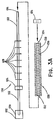
- FIG. 3A is a side view of a second coating assembly.
- FIG. 3B is a side view of third coating assembly with a first axial member component.
- FIG. 3C is a side view of the third coating assembly shown in FIG. 3B with a first axial member component and a second axial member component.
- FIG. 4 is a side view of a third mounted endoluminal medical device coating assembly.
- FIG. 5 is a transverse cross-sectional view of a portion of the first coating assembly in FIG. 1 during spray coating of the mounted endoluminal medical device.
- the present disclosure relates to methods of coating an endoluminal medical device, and mandrels configured to coat an endoluminal medical device.
- coating refers generally to material attached to an implantable medical device.
- a coating can include material covering any portion of a medical device, and can be configured with one or more coating layers.
- a coating can have a substantially constant or a varied thickness and composition. Coatings can be adhered to any portion of a medical device surface, including the luminal surface, the abluminal surface, or any portions or combinations thereof.
- proximal and distal describe longitudinal directions in opposing axial ends of a mounted endoluminal medical device coating assembly, and components thereof.
- securing contact between an annular projection and a medical device refers to physical contact between a surface of the annular projection and a surface of the medical device that is effective to maintain the medical device in a fixed orientation with respect to the axial member during translational or rotational movement of the axial member.
- the phrase “therapeutic agent” refers to any pharmaceutically active agent that results in an intended therapeutic effect on the body to treat or prevent conditions or diseases.
- the therapeutic agent is an agent effective to treat or prevent restenosis, such as an antisense agent, a microtubule stabilizing agent or an inhibitor of the mammalian target of rapamycin (mTOR).
- Preferred therapeutic agents include the paclitaxel [ ⁇ -(benzoylamino)- ⁇ -hydroxy-,6,12b-bis-(acetyloxy)-12-(benzoyloxy)-2a,3,4,4a,5,6,9,10,11,12,12a,12b-dodecahydro-4,11-dihydroxy-4a,8,13,13-tetramethyl-5-oxo-7,11-methano-1H-cyclodeca(3,4)benz(1,2-b)-oxet-9-ylester,(2aR-(2a- ⁇ ,4- ⁇ ,4a- ⁇ ,6- ⁇ ,9- ⁇ -( ⁇ -R*, ⁇ -S*), 11- ⁇ , 12- ⁇ , 12a- ⁇ ,2b- ⁇ ))-benzenepropanoic acid] and bupivacaine [1-butyl-N-(2,6-zimethylphenyl)piperidine-2-carboxamide].
- a mandrel coating assembly 10 extends from a proximal end 2 to a distal end 4 and includes an axial member 22 and one or more annular projections, such as the pair of spacing rings 24 a , 24 b extending radially from the axial member 22 .
- the annular projections may have a diameter that is greater than the diameter of the axial member 22 and are securely attached to the axial member 22 such that translational and rotational motion of the axial member 22 is uniformly and efficiently imparted to the annular projections.
- the annular projections have substantially similar ring shapes and have at least one surface configured to securely contact a medical device 30 mounted on the coating assembly 10 .
- Annular projections may be configured to fit within the lumen of a mounted medical device, and/or between axially stacked, longitudinally adjacent mounted medical devices.
- the pair of spacing rings 24 a , 24 b may be attached to the axial member 22 by welding or soldering each spacing ring 24 a , 24 b at a fixed longitudinal distance from each other.
- a first spacing ring 24 a may be affixed to the axial member 22
- a second spacing ring 24 b may be translated along the axial member 22 and locked into place at a desired position.
- both the first spacing ring 24 a and second spacing ring 24 b can be translated along the axial member 22 into place at a desired position, usually to optimize the spray pattern.
- the axial member 22 and the second spacing ring 24 b may include a means 25 for securing the first spacing ring 24 a , the second spacing ring 24 b , or both, at one or more positions along the axial member 22 , such as an interlocking set of complementary projections and apertures on the spacing rings 24 a , 24 b and the axial member 22 .
- Other examples of the means 25 of securing can include other mechanical means, including adhesives, soldering, a collet, a flexible member with a high coefficient of friction, such as a silicone tubular member with a slit, which can allow the flexible member to be easily removed and reapplied at the desired location.
- the annular projections are preferably formed from the same material as the axial member 22 , although they may be formed from any material that may be fixedly attached to the axial member 22 and have sufficient rigidity to translate physical motion of the axial member 22 to a medical device in securing contact with the annular projection.
- FIG. 2A is a detailed side view of the spacing ring 24 b , an annular ring having an outer diameter 56 and an inner diameter 54 enclosing a hole 23 .
- the inner diameter 54 may be substantially equal to the outer diameter of the axial member 22 and hole 23 is configured to receive the axial member 22 .
- the spacing ring 24 b may be adapted to slide along the axial member 22 from the distal end 4 in the proximal direction to a desired position, where the spacing ring 24 b may be secured to the axial member by the means for securing 25 .
- the outer diameter 56 is typically greater than the outer diameter of the vascular stent 30 .
- the spacing ring 24 b may include a groove 58 having a diameter substantially equal to the diameter of the vascular stent 30 in the expanded configuration and having a thickness approximately equal to or greater than the thickness of the vascular stent 30 .
- FIG. 2B shows a transverse cross sectional view of the spacing ring 24 b shown in FIG. 2A , including the hole 23 , inner diameter 54 , outer diameter 56 and groove 58 .
- the spacing ring 24 b may also have a second groove 58 ′ on the side opposite the first groove 58 .
- the second groove 58 ′ may be otherwise identical to the first groove 58 or optionally may have a different diameter.
- the grooves 58 , 58 ′ are preferably a V-shaped groove having 60° sides, but can be any angle suitable to support a tubular medical device and/or to minimize the covering of the edge.
- the grooves can be rectangular or even U-shaped suitable for the same purpose.
- Examples of preferred ratios between the radius of the groove 58 may be about 60-75% of the outer diameter 56 , including groove 58 radii that are 62%, 69% and 74% of the outer diameter 56 .
- the spacing ring 24 b may be made from any suitable material, such as 302 stainless steel.
- a tubular medical device such as a vascular stent 30 , may be positioned around the mandrel coating assembly 10 .
- the tubular medical device preferably includes a plurality of holes between the abluminal surface and the luminal surface defining a cylindrical lumen extending longitudinally through the tubular medical device.
- the tubular medical device may comprise a plurality of apertures or open spaces between metallic filaments (including fibers and wires), segments or regions.
- Typical structures include: an open-mesh network comprising one or more knitted, woven or braided metallic filaments; an interconnected network of articulable segments; a coiled or helical structure comprising one or more metallic filaments; and, a patterned tubular metallic sheet (e.g., a laser cut tube).
- intraluminal stents examples include endovascular, biliary, tracheal, gastrointestinal, urethral, ureteral, esophageal and coronary vascular stents.
- the intraluminal stents of the present invention may be, for example, balloon-expandable or self-expandable.
- a vascular stent 30 may include a plurality of interconnected struts and bends in a plurality of longitudinally connected sinusoidal hoop members.
- the tubular medical device may be radially expandable from a compressed configuration to a radially expanded configuration.
- the vascular stent 30 is shown in an expanded configuration including a lumen with a first diameter.
- the inner diameter of the lumen is preferably greater than the diameter of the axial member 22 .
- the vascular stent 30 may be, for example, a Wallstent, Palmaz-Shatz, Wiktor, Strecker, Cordis, AVE Micro Stent, Igaki-Tamai, Millenium Stent (Sahajanand Medical Technologies), Steeplechaser stent (Johnson & Johnson), Cypher (Johnson & Johnson), Sonic (Johnson & Johnson), BX Velocity (Johnson & Johnson), Flexmaster (JOMED) JoStent (JOMED), S7 Driver (Medtronic), R-Stent (Orbus), Tecnic stent (Sorin Biomedica), BiodivYsio (Abbott), Trimaxx (Abbott), DuraFlex (Avantec Vascular), NIR stent (Boston Scientific), Express 2 stent (Boston Scientific), Liberte stent (Boston Scientific), Achieve (Cook/Guidant),
- the stent is a vascular stent such as the commercially available Gianturco-Roubin FLEX-STENT®, GRIITM, SUPRA-G, ZILVER or V FLEX devices from Cook Incorporated (Bloomington, Ind.).
- the vascular stent 30 may be mounted on the mandrel coating assembly 10 between the first spacing ring 24 a and the second spacing ring 24 b .
- Each spacing ring 24 a , 24 b may have a diameter that is greater than both the axial member 22 and the diameter of the lumen of the vascular stent 30 in the expanded configuration.
- no portion of the spacing rings 24 a , 24 b extends through openings in the mounted vascular stent 30 .
- the proximal and distal ends of the vascular stent 30 may be in securing contact with the first spacing ring 24 a and the second spacing ring 24 b , respectively, to maintain the vascular stent 30 in a floating position.
- the luminal surface of the vascular stent 30 can be spaced apart from and substantially parallel to the axial member 22 .
- the luminal surface of the vascular stent 30 preferably does not contact the axial member 22 in order to reduce the potential of coating irregularities such as “webbing.”
- the vascular stent 30 may be positioned and mounted on the mandrel coating assembly 10 by: (1) removing the second spacing ring 24 b from the mandrel coating assembly 10 , (3) positioning the vascular stent 30 around the distal end of the axial member 22 , (4) longitudinally translating the vascular stent 30 toward the proximal end of the mandrel coating assembly 10 until the proximal end of the vascular stent 30 contacts the first spacing ring 24 a , (5) positioning the second spacing ring 24 b around the distal end of the axial member 22 and sliding the second spacing ring 24 b toward the proximal end 2 of the mandrel coating assembly 10 to bring the second spacing ring 24 b into securing contact with the distal end of the vascular stent 30 and (6) securing the second spacing ring 24 b to the axial member 22 to secure the vascular stent 30 to the mandrel coating assembly 10 .
- one or more spacing rings 24 a , 24 b having a diameter greater than that of the vascular stent 30 may be positioned at both ends of the vascular stent 30 , with each spacing ring adapted to retain the vascular stent 30 substantially parallel to, and spaced apart from, the axial member 22 .
- the vascular stent 30 does not contact the axial member 22 .
- the axial member 22 may be a solid cylindrical member oriented along a longitudinal axis of the coating assembly 10 , and may be formed from a rigid material adapted to translate rotational force from the proximal shaft mount 26 throughout the length of the axial member 22 .
- the axial member 22 may be a stainless steel mandrel having a substantially uniform circular transverse cross-section with a substantially uniform diameter along the length of the mandrel.
- the proximal shaft mount 26 may have a circular transverse cross-section with a diameter that is greater than the diameter of the medical device positioned around the axial member 22 when mounted to the mandrel coating assembly 10 .
- the mandrel coating assembly is rotated while coating a medical device mounted thereto.
- the axial member 22 may be attached to a means for imparting rotational motion to the axial member 22 .
- the distal end of a proximal shaft mount 26 is adapted to securely receive the proximal end of the axial member 22 and impart rotational motion thereto.
- the axial member 22 may be secured to the proximal shaft mount 26 by any conventional means, including a screw, bolt, adhesive, weld or other retaining means.
- FIG. 3A shows a second exemplary mandrel coating assembly 100 extending from a proximal end 102 to a distal end 104 and including an axial member 122 of a first diameter and a proximal end secured to a rotating proximal shaft mount 126 .
- a plurality longitudinally spaced annular support rings 128 positioned between a pair of spacing rings 124 are together disposed along the length of the axial member 122 .
- the annular support rings 128 may have a second diameter that is greater than the first diameter of the axial member 122 ; the spacing rings 124 may have a third diameter that is greater than the second diameter.
- the annular support rings 128 have a second diameter that is substantially similar to the diameter of the luminal surface of a vascular stent.
- the vascular stent 130 may be positioned around and mounted to the mandrel coating assembly 100 .
- the vascular stent 130 may include a plurality of interconnected struts 136 defining a plurality of openings 138 radially extending between an abluminal (outer) surface and a luminal (inner) surface defining a cylindrical lumen with a fourth diameter extending from a proximal end 132 to a distal end 134 .
- the fourth diameter is preferably substantially equal to the second diameter of the annular support rings 128 .
- the distal spacing ring 124 may be removed from the axial member 122 prior to positioning and mounting the vascular stent 130 .
- the vascular stent 130 is positioned around the distal end of the axial member 122 and translated toward the proximal end 102 of the mandrel coating assembly 100 until the proximal end 132 of the vascular stent 130 contacts a spacing ring 124 .
- the luminal surface of the vascular stent 130 may be mounted by placing the luminal surface of the vascular stent 130 in securing contact with the plurality of annular support rings 128 positioned within the lumen.
- the luminal surface of the mounted vascular stent 130 may be oriented substantially parallel to and spaced apart from the axial member 122 .
- a spacing ring 124 may be subsequently positioned around the axial member 122 and longitudinally translated into contact with the distal end 134 of the mounted vascular stent 130 .
- the spacing ring 124 can be affixed to the axial member 122 by the means 125 for securing.
- FIG. 3B illustrates the mandrel coating assembly that can be broken into components that can assist in the positioning and mounting of the vascular stent 130 around the mandrel coating assembly 100 .
- a first axial member component 140 a can have a proximal end that is secured to a rotating proximal shaft mount 126 .
- the first axial member 140 a can include a spacing ring 124 a that can be translated along the first axial member component 140 a and affixed to the first axial member component 140 a at a desired location by the means 125 for securing.
- the first axial member component 140 a can also include a plurality of annular support rings 128 a .
- the coupling means 142 can be quickly engaged and disengaged with another axial member component.
- the coupling means 142 at the distal end of the first axial member component 140 a is a tapped hole (female) to be threadably engaged with threaded shaft (male) of another axial member component.
- Other examples of the coupling means 142 can include pin, friction fitting, compression fitting, or any other suitable coupling means.
- the vascular stent 130 is positioned around the distal end of the first axial member component 140 a and translated toward the proximal end of the mandrel coating assembly 100 until the proximal end 132 of the vascular stent 130 contacts the spacing ring 124 a .
- the luminal surface of the vascular stent 130 may be mounted by placing the luminal surface of the vascular stent 130 in securing contact with the plurality of annular support rings 128 a positioned within the lumen.
- the luminal surface of the mounted vascular stent 130 may be oriented substantially parallel to and spaced apart from the axial member 122 .
- a second axial component 140 b can include a spacing ring 124 b that can be affixed to the second axial member component 140 b .
- the second axial member component 140 b can also include the plurality of annular support rings 128 b .
- At the distal end, the proximal end, or both, of the second axial member component 140 b are the coupling means 142 .
- the coupling means 142 at the proximal end of the second axial member component 140 b is a threaded shaft (male) and at the distal end of the second axial member component 140 b is a tapped hole (female).
- the proximal end of the second axial member component 140 b is coupled to the distal end of the first axial member component 140 a , causing the spacing ring 124 b of the second axial member component 140 b to be longitudinally translated into contact with the distal end 134 of the mounted vascular stent 130 .
- Additional axial member components can be coupled to the mandrel coating assembly 100 depending on the number of vascular stents to be coated. Each axial member component can have a uniform diameter that is less than the diameter of the lumen of the vascular stent 130 .
- the diameters of the axial member components 140 a , 140 b , the annular spacing rings 124 a , 124 b , the annular grooves 58 , 58 ′ and the annular support rings 128 a , 128 b can vary proportionally to the diameter of the respective vascular stent.
- the second axial member component 140 b in FIG. 3C is sized for a smaller vascular stent.
- the diameter of the second axial member component 140 b is less than the diameter of the first axial member component 140 a .
- the diameter of the annular support rings 128 b of the second axial member component 140 b is less than the diameter of the annular support rings 128 a of the firs axial member component 140 a .
- the diameter of the spacing ring 124 b of the second axial member component 140 b is less than the diameter of the spacing rings 124 a of the first axial member component 140 a .
- the spacing ring 124 b of the second axial member component 140 b also includes grooves 129 a , 129 b having different diameters corresponding to the vascular stents on the proximal side and the distal side of the spacing ring 124 b.
- the annular support rings 128 can be included on the axial member 122 .
- the annular support rings 128 can be machined with the axial member 122 as a single piece or can be machined separately and attached by mechanical means, such as adhesives, soldering, or the like.
- the edge of the annular support rings 128 is shaped to a point or tip to minimize contact with the substantially all of the luminal surface of the vascular stent 130 where the edge contacts.
- the annular support rings 128 can be spaced by any suitable dimension (generally up to 30 mm) to prevent the vascular stent 130 from sagging and/or to keep the abluminal surface of the vascular stent a uniform distance from the coating nozzle.
- any suitable dimension generally up to 30 mm
- one support ring can be provided at about 30 mm from the spacing rings.
- two support rings can be provided at about 20 mm from the spacing rings and each other.
- FIG. 4 shows a third mandrel coating assembly 200 extending from a proximal end 202 to a distal end 204 , and including an axial member 222 attached to a proximal shaft mount 226 adapted to rotate the axial member 222 around the longitudinal axis of the mandrel coating assembly 200 .
- the mandrel coating assembly 200 may include a plurality of spacing rings 224 having an inner diameter that is substantially equal to the outer diameter of the axial member 222 . Each spacing ring 224 is attached to the axial member 222 by the means for securing 125 .
- a series of tubular medical devices 230 can be mounted with the luminal surface of each medical device 230 in securing contact with spacing rings 224 .
- the inner diameter of the medical devices 230 can be substantially equal to the outer diameter of the spacing rings 224 .
- the series of tubular medical devices 230 can be mounted with the proximal and distal ends of each medical device 230 in securing contact with an annular groove 58 , 58 ′ in the spacing rings 224 .
- the inner diameter of the medical device 230 can be less than the outer diameter of the spacing rings 224 .
- the luminal surfaces of the mounted medical devices 230 are maintained substantially parallel to and spaced apart from the outer surface of the axial member 222 . Rotation and translation of the axial member 222 is imparted to the mounted medical devices 230 .
- a medical device mounted on a mandrel coating assembly may be coated with a therapeutic agent.
- the mandrel coating assembly may be configured to localize coating of the therapeutic agent to the abluminal surface of the medical device, prevent or reduce coating irregularities such as “webbing,” and improve coating uniformity.
- a therapeutic agent may be applied by spraying a coating solution including the therapeutic agent and a solvent onto the abluminal surface of the tubular medical device mounted on the mandrel coating assembly.
- FIG. 5 is a cross sectional view along line 5 - 5 in FIG. 1 , showing a coating solution spray 44 exiting a nozzle 40 and contacting the abluminal surface of the vascular stent 30 .
- the coating solution 42 containing a therapeutic agent is passed through the nozzle 40 in a manner effective to atomize the coating solution 42 to form the spray 44 .
- a portion 44 b of the spray 44 passes through the holes through a portion 36 b of the abluminal surface 36 of the vascular stent 30 and contacts the axial member 22 .
- the shape of the spray 44 may be a conical plume controlled such that the maximum distance 52 across the spray 44 is less than the diameter of the axial member 22 .
- the shape of the spray 44 may be controlled by the size and shape of the nozzle 40 and the pressure applied to the coating solution 42 .
- the spray 44 preferably terminates at the axial member 22 .
- the axial member 22 may have an outer diameter large enough to occlude the spray 44 from directly contacting the luminal surface 35 of the vascular stent 30 opposite the position of the nozzle 40 .
- a portion of the spray 44 may indirectly contact the luminal surface of the vascular stent 30 by deflection of the spray 44 from the abluminal surface or edges of the vascular stent 30 during spray coating.
- the mounted vascular stent 30 is maintained substantially parallel to and spaced apart from the axial member 22 , and is preferably rotated during the spray coating process.
- the nozzle 40 may be rastered longitudinally along the length of the axial member 22 to apply a coating along the length of the vascular stent 30 .
- the therapeutic agent is coated onto an implantable medical device by an ultrasonic spray deposition (USD) process.
- the medical device may be coated using an ultrasonic spray nozzle 40 , such as those available from Sono-Tek Corp., Milton, N.Y.
- Ultrasonic nozzles employ high frequency sound waves generated by piezoelectric transducers which convert electrical energy into mechanical energy. The transducers receive a high frequency electrical input and convert this into vibratory motion at the same frequency. This motion is amplified to increase the vibration amplitude at an atomizing surface.
- the ultrasonic nozzle may be configured such that excitation of the piezoelectric crystals creates a longitudinal standing wave along the length of the nozzle.
- the ultrasonic energy originating from the transducers undergoes a step transition and amplification as the standing wave traverses the length of the nozzle.
- the nozzle is designed such that a nodal plane is located between the transducers.
- the nozzle tip is preferably located at an anti-node, where the vibration amplitude is greatest.
- the nozzle's length is preferably a multiple of a half-wavelength. In general, high frequency nozzles are smaller, create smaller drops, and consequently have smaller maximum flow capacity than nozzles that operate at lower frequencies.
- a spray solution 42 introduced onto the atomizing surface absorbs some of the vibrational energy, setting up wave motion in the liquid on the surface.
- the vibrational amplitude of the atomizing surface should be carefully controlled. Below a certain critical amplitude, the energy is insufficient to produce atomized drops. If the amplitude is excessively high, cavitation occurs. Only within a narrow band of input power is the amplitude ideal for producing the nozzle's characteristic fine, low velocity mist. Since the atomization mechanism relies only on liquid being introduced onto the atomizing surface, the rate at which liquid is atomized depends solely on the rate at which it is delivered to the surface.
- the spray solution 42 may be loaded into a syringe, which is mounted onto a syringe pump and connected to a tube that carries the solution to the ultrasonic nozzle.
- the syringe pump is then used to purge the air from the solution line and prime the line and spray nozzle with the solution.
- the stent is loaded onto a mandrel in the ultrasonic coating chamber.
- the stent is held on a mandrel by the annular projections.
- the stent is floating, i.e., does not touch any part of the mandrel, preventing a webbed coating between struts, and the luminal surface is not coated.
- the medical device may be a stent 6-8 mm in diameter that is mounted on a mandrel coating assembly. Other sized stents and mandrels may also be used in the present invention.
- the mandrel is fastened onto a motor, positioned below the ultrasonic nozzle.
- the motor rotates the mandrel at a pre-set speed and translationally moves it so that all parts of the stent pass underneath the ultrasonic spray.
- the rotational speed is set to 10 rpm and the translational speed is set to 0.01 mm per second.
- the rotational speed is set to 60 rpm and the translational speed is set to 0.05 mm per second.
- the rotational speed is set to 30-150, preferably about 110 rpm, and the translational speed is set to 0.19 mm per second.
- Other speeds and combinations may also be used in the present invention.
- Preferred coating parameters for USD using a Sono-tek Model 8700-60 ultrasonic nozzle are provided in Table 1 below.
- the coating solution 42 preferably includes a therapeutic agent and a solvent.
- the solvent may be selected to dissolve the therapeutic agent and readily evaporate within the spray 44 or on the abluminal surface of the vascular stent 30 .
- a coating comprising a therapeutic agent can be formed on the abluminal surface of the medical device by applying the coating solution 42 consisting essentially of the therapeutic agent and an evaporative solvent.
- the coating solution 42 does not contain a bioabsorbable elastomer.
- the therapeutic agent may be paclitaxel and the solvent may be ethanol or methanol.
- a coating solution 42 of about 0.5-5.0 mM paclitaxel in ethanol may be used, and preferably, coating solution 42 includes 0.7 mM or 1.2 mM paclitaxel in ethanol.
- Other therapeutic agents and solvents may also be used in solutions at concentrations permitting desirable deposition rates forming coatings with desired durability.
- a biodegradable material such as a bioabsorbable elastomer (such as PLA) may also be sprayed onto the medical device, and is preferably dissolved in a solvent mixture comprising a mixture of dichloromethane:methanol in a 1:2 (+/ ⁇ 10%) ratio by volume.
- the solvent mixture can comprise about 50-80% methanol and about 20-50% dichloromethane (by volume). More desirably, the mixture is about 65-75% methanol and about 25-40% dichloromethane (by volume). Even more desirably, the mixture is about 70% methanol and about 30% dichloromethane (by volume).
- the bioabsorbable elastomer may be a polyhydroxyalkanoate compound, a hydrogel, poly(glycerol-sebacate) or an elastin-like peptide.
- the bioabsorbable elastomer includes a polyhydroxyalkanoate bioabsorbable polymer such as polylactic acid (poly lactide), polyglycolic acid (poly glycolide), polylactic glycolic acid (poly lactide-co-glycolide), poly-4-hydroxybutyrate, or a combination of any of these.
- the bioabsorbable elastomer comprises a poly- ⁇ -hydroxy acid, such as polylactic acid (PLA).
- PLA can be a mixture of enantiomers typically referred to as poly-D,L-lactic acid.
- the bioabsorbable elastomer is poly-L(+)-lactic acid (PLLA) or pol-D( ⁇ )-lactic acid (PDLA), which differ from each other in their rate of biodegradation.
- the coating method may be repeated after the application of the therapeutic agent coating to the abluminal surface of the medical device.
- a second layer comprising a bioabsorbable elastomer material can be dissolved in a solvent to form a second coating solution 42 that may be subsequently sprayed onto a layer of therapeutic agent that was previously deposited on the medical device.
- the polymer is PLA and the solvent is dichloromethane. More desirably, about 0.1-7.0 g/L of PLA in dichloromethane is used. Even more desirably, about 2.5-6.5 g/L and most desirably, 5.0 g/L of PLA in dichloromethane is used.
- a second coating solution of about 2-4 g/L of a bioabsorbable elastomer such as PLA in a suitable solvent such as dichloromethane can be applied using an ultrasonic nozzle.
- Multiple coating layers may be separately applied sequentially using an ultrasonic nozzle spray coating technique employing ultrasound to atomize the spray solution to provide a smooth and uniform polymer coating.
- the polymer coating is applied from an ultrasonic nozzle.
- Stents with coatings consisting of paclitaxel may be prepared by spray coating a solution comprising paclitaxel, methanol and water.
- a 1.74 mM paclitaxel solution may be prepared in 68% methanol by dissolving 7.43 mg of paclitaxel in 5 mL of previously made solution of 68% methanol 32% water.
- the solution may be sprayed from an ultrasonic spray gun (Sono-tek Model 06-04372) in a glove box. Before spraying, the glove box may be purged with nitrogen at 20 psi for 15 minutes. The atmosphere in the glove box may be adjusted until the oxygen meter reads a constant 200 ppm within the glove box.
- the heat in the glovebox may be set to 31° C.
- the paclitaxel solution may be loaded into a syringe and placed on the syringe pump in the ultrasonic coating apparatus and a bare metal stent (for example, 6 ⁇ 20 ZILVER, Cook Inc., Bloomington, Ind.) may be mounted on a mandrel aligned with the spray nozzle.
- a bare metal stent for example, 6 ⁇ 20 ZILVER, Cook Inc., Bloomington, Ind.
- the solution may be sprayed onto a stent using a 60 kHz nozzle at a flow rate of 0.03 mL/min, a coating velocity of 0.025 in/sec, a nozzle power of 1.0 W, a process gas pressure of 2.0 psi, and a distance from the nozzle to the stent of about 12 mm, while rotating the stent with an axial rotation rate of 60 rpm.
- a mandrel coating assembly described above is used, with the diameter of the axial member being larger than the maximum width of the spray contacting the axial member. Only the abluminal surface of the stent is coated.
- Paclitaxel may be applied to a Zilver® stent by dissolving Paclitaxel in ethanol at a concentration of about 2.4 mM as described in Example 1.
- a biodegradable PLA polymer is applied by dissolving 2 to 4 g/L in dichloromethane (a second coating solution).
- the second coating solution may be applied by using the ultrasonic nozzle.
- the second coating solution is loaded into a 10.0 mL syringe, which is mounted onto a syringe pump and connected to a tube that carries the solution to a spray head.
- the syringe pump is then used to purge the air from the solution line and prime the line and spray nozzle with the solution.
- the ultrasonic nozzle is arranged such that excitation of the piezoelectric crystals generates a transverse standing wave along the length of the nozzle.
- the solution introduced onto the atomizing surface may absorb some of the vibrational energy, creating a wave motion in the liquid.
- the vibrational amplitude of the atomizing surface may be carefully controlled.
- the coating chamber is purged with nitrogen to displace any oxygen in the system
- One end of the stent is slipped onto a mandrel and half of the stent is coated.
- the nozzle is manually aligned to the tip of the stent and the middle of the stent. These position numbers are used for the coating program when the syringe pump is actually activated.
- the stent orientation is reversed and the other half is coated.
- the stent is kept at ambient temperature and in a closed chamber.
- the coating solution 42 may be applied using an electrostatic spray deposition (ESD) process by an electrostatic spraying apparatus (Teronics Development Corp.).
- ESD electrostatic spray deposition
- the ESD process may especially be desirable when the therapeutic agent is hydrophilic.
- the solution that is to be deposited on the target is typically charged to several thousand volts (typically negative) and held at ground potential. The charge of the solution is generally great enough to cause the solution to jump across an air gap of several inches before landing on the target. As the solution is in transit towards the target, it fans out in a conical pattern which aids in a more uniform coating.
- the electrons are further attracted towards the metal portions of the target, rather than towards the non conductive base the target is mounted on, leaving the coating mainly on the target only.
- the ESD method allows for control of the coating composition and surface morphology of the deposited coating.
- the morphology of the deposited coating may be controlled by appropriate selection of the ESD parameters, as set forth in WO 03/006180 (Electrostatic Spray Deposition (ESD) of biocompatible coatings on Metallic Substrates), incorporated herein by reference.
- a coating having a uniform thickness and grain size, as well as a smooth surface may be obtained by controlling deposition conditions such as deposition temperature, spraying rate, precursor solution, and bias voltage between the spray nozzle and the medical device being coated.
- deposition conditions such as deposition temperature, spraying rate, precursor solution, and bias voltage between the spray nozzle and the medical device being coated.
- the deposition of porous coatings is also possible with the ESD method.
- the coating solution 42 may be applied using a pressure spray gun.
- a pressure spray gun manufactured (notorious for cloud of spray) by Badger (Model No. 200), in a fume hood, with a fluid dispensing system connected to a pressure source (nitrogen) until the target dose of drug is reached. Adjustments on the system may be made to control the spray pattern and the amount of fluid dispensed.
- the spray gun may be aligned with the stents by setting a laser beam even with the nozzle of the spray gun and positioning the stents so that the laser beam is located at approximately 1 ⁇ 4 the distance from the top of the stents.
- the spray gun which may be positioned parallel to the hood floor and at a horizontal distance of approximately 5-7 inches from the stents, may then be passed over the surface of the stents until a predetermined volume of spray is dispensed.
- the stents may then be rotated approximately 90° and the spraying procedure may be repeated until the entire circumference of each stent is coated.
- the movement of the gun may be slow enough to allow the solvent to evaporate before the next pass of the gun.
- Each spray application may cover approximately 90° of the circumference of the stents.
- the stents may be kept at ambient temperature and humidity during the spraying process. After substantially all of the solvent has evaporated, a coating of paclitaxel is left on the abluminal surface of the stent.
- Paclitaxel may be applied to Zilver® stents (nitinol stents manufactured by Cook Inc., Bloomington, Ind.) ranging in size from about 6 ⁇ 20 mm to about 14 ⁇ 80 mm, or any size, as follows.
- paclitaxel can be dissolved in ethanol to form a 2.4 mM solution.
- the paclitaxel may be substantially dissolved within about 30 minutes, using sonication. This solution may be used to set the flow rate of the spray gun to the target flow rate of approximately 5.7 ml/min.
- the stent is held on a mandrel by the annular projections.
- the stent is floating, i.e., does not touch any part of the mandrel, preventing a webbed coating between struts, and the luminal surface is not coated.
- Approximately 25 ml of the paclitaxel solution may be added to the spray gun reservoir of the pressure spray gun.
- the coating solution 42 may be applied using a pressure spray gun, in a fume hood, with a fluid dispensing system connected to a pressure source (nitrogen) until the target dose of paclitaxel is reached.
- Paclitaxel may first be applied to Zilver® stents (nitinol stents manufactured by Cook Inc., Bloomington, Ind.) ranging in size from about 6 ⁇ 20 mm to about 14 ⁇ 80 mm (or any size), as described in Example 3.
- Zilver® stents nitinol stents manufactured by Cook Inc., Bloomington, Ind.
- a layer of PLA may be spray deposited over the paclitaxel coating using the same type of pressure spray coating apparatus as Example 3.
- a second coating solution of approximately 2-4 g/L of PLA in dichloromethane may be prepared without paclitaxel, filtered over a 0.2 micron nylon filter, and collected in a flask.
- the second coating solution may then be sprayed over the coating of paclitaxel on the abluminal surface of the stent using a procedure similar to the one described above with respect to Example 3.
- the spraying may be performed at two different heights.
- the stents may be positioned with the spray gun nozzle positioned between the midpoint and the proximal end, sprayed, and rotated until the circumference of the top portion of the stents are coated.
- the stents may be positioned with the spray gun nozzle positioned between the midpoint and the distal end, sprayed, and rotated until the circumference of the bottom portion of the stents are coated.
- paclitaxel may be applied to a Zilver® stent by dissolving paclitaxel in ethanol (using sonication) at a concentration of about 2.4 mM and applying the solution to a stent with the electrostatic spraying apparatus.
- the solution may be loaded into a 20 mL syringe, which is then mounted onto a syringe pump and connected to a tube that carries the solution to a spray head.
- the syringe pump may be used to purge the air from the solution line and prime the line and spray nozzle with solution.
- An electrical connection to the nozzle may supply the required voltage.
- the stent may be slipped over a mandrel (Teronics Development Corp., 6 mm ⁇ 60 mm) until one end of the stent made contact with the electrical connection at one end of the mandrel. This connection provides the ground potential to the stent.
- the motor may be activated and the stent rotated at a constant, slow speed.
- the syringe pump may then be activated to supply the nozzle with a consistent flow of solution, and the power supply may be activated to provide a charge to the solution and cause the solution to traverse the air gap and land on the stent surface. As the coated surfaces are rotated away from the spray path, the volatile portion of the solution evaporates leaving a coating of therapeutic agent behind.
- the stent continues to rotate in the spray pattern until the desired dose has been deposited on the abluminal surface.
- the stent is kept at ambient temperature and humidity, the solution is pumped at a rate of about 0.5-10 mL/hr, preferably about 0.5-8 mL/hr through the spray gun (which is placed at a horizontal distance of approximately 6 cm from the stents), and the bias voltage between the spray nozzle and the stent is approximately 5-20 kilovolts, preferably about 12 kilovolts.
- Substantially all of the solvent is evaporated during the spraying process, leaving a dose of about 0.1 micrograms-3 micrograms of paclitaxel per square millimeter on the abluminal surface area of the stent.
- a layer of biodegradable polymer may optionally be applied over the paclitaxel coating by dissolving approximately 1.2 g/L ( ⁇ 0.3 g/L) of PLA in a 2:1 v/v mixture of methanol and dichloromethane to obtain a finer spray that is more conducive to electrostatic spraying than the spray created by dissolving paclitaxel in dichloromethane alone.
- the solution is then applied to the stent by using an electrostatic spray deposition process as described above.
Abstract
Description
| TABLE 1 |
| Ultrasonic Spray Deposition Parameters for Sono-tek Model 8700-60 |
| Coating | Rotation | Nozzle | Process | ||
| Flow rate | velocity | Speed | Power | Gas | Distance |
| (mL/min) | (in/sec) | (rpm) | (watts) | (psi) | (mm) |
| 0.01-2 | 0.01-0.5 | 30-150 | 0.9-1.2 | 0.1-2.5 | 1-25 |
The coating is preferably applied within an enclosed chamber purged with nitrogen to displace oxygen in the system. During the process, the stent is kept at ambient temperature and in a closed chamber.
| TABLE 2 |
| Process Parameters for Ultrasonic Coating |
| Coating | Rotation | Nozzle | Process | ||
| Flow rate | velocity | Speed | Power | Gas | Distance |
| (mL/min) | (in/sec) | (rpm) | (watts) | (psi) | (mm) |
| 0.01-2 | 0.005-0.5 | 30-150 | 0.9-1.2 | 0.1-2.5 | 1-25 |
Claims (20)
Priority Applications (1)
| Application Number | Priority Date | Filing Date | Title |
|---|---|---|---|
| US12/199,189 US8092864B2 (en) | 2007-08-28 | 2008-08-27 | Mandrel and method for coating open-cell implantable endovascular structures |
Applications Claiming Priority (2)
| Application Number | Priority Date | Filing Date | Title |
|---|---|---|---|
| US96843607P | 2007-08-28 | 2007-08-28 | |
| US12/199,189 US8092864B2 (en) | 2007-08-28 | 2008-08-27 | Mandrel and method for coating open-cell implantable endovascular structures |
Publications (2)
| Publication Number | Publication Date |
|---|---|
| US20090061072A1 US20090061072A1 (en) | 2009-03-05 |
| US8092864B2 true US8092864B2 (en) | 2012-01-10 |
Family
ID=40407923
Family Applications (1)
| Application Number | Title | Priority Date | Filing Date |
|---|---|---|---|
| US12/199,189 Expired - Fee Related US8092864B2 (en) | 2007-08-28 | 2008-08-27 | Mandrel and method for coating open-cell implantable endovascular structures |
Country Status (1)
| Country | Link |
|---|---|
| US (1) | US8092864B2 (en) |
Cited By (13)
| Publication number | Priority date | Publication date | Assignee | Title |
|---|---|---|---|---|
| US9199261B2 (en) * | 2011-10-13 | 2015-12-01 | Abbott Cardiovascular Systems Inc. | Adjustable support for tubular medical device processing |
| US10315217B2 (en) * | 2014-06-18 | 2019-06-11 | Kaneka Corporation | Method for manufacturing elastic tubular body |
| US10668188B2 (en) | 2012-10-26 | 2020-06-02 | Urotronic, Inc. | Drug coated balloon catheters for nonvascular strictures |
| US10806830B2 (en) | 2012-10-26 | 2020-10-20 | Urotronic, Inc. | Drug-coated balloon catheters for body lumens |
| US10850076B2 (en) | 2012-10-26 | 2020-12-01 | Urotronic, Inc. | Balloon catheters for body lumens |
| US10881839B2 (en) | 2012-10-26 | 2021-01-05 | Urotronic, Inc. | Drug-coated balloon catheters for body lumens |
| US10888640B2 (en) | 2015-04-24 | 2021-01-12 | Urotronic, Inc. | Drug coated balloon catheters for nonvascular strictures |
| US10898700B2 (en) | 2012-10-26 | 2021-01-26 | Urotronic, Inc. | Balloon catheters for body lumens |
| US11096774B2 (en) | 2016-12-09 | 2021-08-24 | Zenflow, Inc. | Systems, devices, and methods for the accurate deployment of an implant in the prostatic urethra |
| US11504450B2 (en) | 2012-10-26 | 2022-11-22 | Urotronic, Inc. | Drug-coated balloon catheters for body lumens |
| US11730864B2 (en) | 2015-04-24 | 2023-08-22 | Urotronic, Inc. | Drug coated balloon catheters for nonvascular strictures |
| US11890213B2 (en) | 2019-11-19 | 2024-02-06 | Zenflow, Inc. | Systems, devices, and methods for the accurate deployment and imaging of an implant in the prostatic urethra |
| US11938287B2 (en) | 2012-10-26 | 2024-03-26 | Urotronic, Inc. | Drug-coated balloon catheters for body lumens |
Families Citing this family (11)
| Publication number | Priority date | Publication date | Assignee | Title |
|---|---|---|---|---|
| US20110034992A1 (en) * | 2009-08-04 | 2011-02-10 | Papp John E | Stent and Method of Coating Same |
| US8389041B2 (en) * | 2010-06-17 | 2013-03-05 | Abbott Cardiovascular Systems, Inc. | Systems and methods for rotating and coating an implantable device |
| WO2012037327A1 (en) * | 2010-09-16 | 2012-03-22 | Mayo Foundation For Medical Education And Research | Mechanically adjustable variable diameter stent |
| KR20140030165A (en) * | 2011-04-04 | 2014-03-11 | 앨리엄 메디컬 솔루션스 리미티드 | System and method for manufacturing a stent |
| US20130035753A1 (en) * | 2011-08-01 | 2013-02-07 | Abbott Cardiovascular Systems Inc. | Multiple Scaffold Design And Coating Thereof |
| CA2961664C (en) * | 2014-10-09 | 2020-04-14 | Boston Scientific Scimed, Inc. | Pancreatic stent with drainage feature |
| CN110944689B (en) | 2017-06-07 | 2022-12-09 | 施菲姆德控股有限责任公司 | Intravascular fluid movement devices, systems, and methods of use |
| CN111556763B (en) | 2017-11-13 | 2023-09-01 | 施菲姆德控股有限责任公司 | Intravascular fluid movement device and system |
| WO2021016372A1 (en) | 2019-07-22 | 2021-01-28 | Shifamed Holdings, Llc | Intravascular blood pumps with struts and methods of use and manufacture |
| WO2021062265A1 (en) | 2019-09-25 | 2021-04-01 | Shifamed Holdings, Llc | Intravascular blood pump systems and methods of use and control thereof |
| WO2022216794A1 (en) * | 2021-04-07 | 2022-10-13 | Shifamed Holdings, Llc | Catheter blood pump shrouds and assembly thereof |
Citations (23)
| Publication number | Priority date | Publication date | Assignee | Title |
|---|---|---|---|---|
| US4739762A (en) | 1985-11-07 | 1988-04-26 | Expandable Grafts Partnership | Expandable intraluminal graft, and method and apparatus for implanting an expandable intraluminal graft |
| US5133732A (en) | 1987-10-19 | 1992-07-28 | Medtronic, Inc. | Intravascular stent |
| US5292331A (en) | 1989-08-24 | 1994-03-08 | Applied Vascular Engineering, Inc. | Endovascular support device |
| US5421955A (en) | 1991-10-28 | 1995-06-06 | Advanced Cardiovascular Systems, Inc. | Expandable stents and method for making same |
| US6090127A (en) | 1995-10-16 | 2000-07-18 | Medtronic, Inc. | Medical stents, apparatus and method for making same |
| US6120847A (en) * | 1999-01-08 | 2000-09-19 | Scimed Life Systems, Inc. | Surface treatment method for stent coating |
| WO2003006180A1 (en) | 2001-07-13 | 2003-01-23 | Stichting Voor De Technische Wetenschappen | Electrostatic spray deposition (esd) of biocompatible coatings on metallic substrates |
| US6517889B1 (en) | 2001-11-26 | 2003-02-11 | Swaminathan Jayaraman | Process for coating a surface of a stent |
| US6565659B1 (en) | 2001-06-28 | 2003-05-20 | Advanced Cardiovascular Systems, Inc. | Stent mounting assembly and a method of using the same to coat a stent |
| US6572644B1 (en) | 2001-06-27 | 2003-06-03 | Advanced Cardiovascular Systems, Inc. | Stent mounting device and a method of using the same to coat a stent |
| US20040013792A1 (en) | 2002-07-19 | 2004-01-22 | Samuel Epstein | Stent coating holders |
| US6818063B1 (en) | 2002-09-24 | 2004-11-16 | Advanced Cardiovascular Systems, Inc. | Stent mandrel fixture and method for minimizing coating defects |
| US20050069630A1 (en) | 2003-09-30 | 2005-03-31 | Advanced Cardiovascular Systems, Inc. | Stent mandrel fixture and method for selectively coating surfaces of a stent |
| US6955723B2 (en) | 2001-06-27 | 2005-10-18 | Advanced Cardiovascular Systems, Inc. | Mandrel for supporting a stent and method of using the mandrel to coat a stent |
| US7060319B2 (en) | 2003-09-24 | 2006-06-13 | Boston Scientific Scimed, Inc. | method for using an ultrasonic nozzle to coat a medical appliance |
| US20060284383A1 (en) | 2005-06-20 | 2006-12-21 | Brettell Charles E | Expandable mandrel |
| US20060286287A1 (en) | 2001-12-28 | 2006-12-21 | Advanced Cardiovascular Systems, Inc. | Method of coating implantable medical devices |
| US20070031611A1 (en) | 2005-08-04 | 2007-02-08 | Babaev Eilaz P | Ultrasound medical stent coating method and device |
| US20070048433A1 (en) | 2003-08-05 | 2007-03-01 | Hallett Martin D | Coating of surgical devices |
| US20070048452A1 (en) | 2005-09-01 | 2007-03-01 | James Feng | Apparatus and method for field-injection electrostatic spray coating of medical devices |
| US7306677B2 (en) | 2004-01-30 | 2007-12-11 | Boston Scientific Corporation | Clamping fixture for coating stents, system using the fixture, and method of using the fixture |
| US7354480B1 (en) | 2003-02-26 | 2008-04-08 | Advanced Cardiovascular Systems, Inc. | Stent mandrel fixture and system for reducing coating defects |
| US7402329B2 (en) | 2001-06-29 | 2008-07-22 | Advanced Cardiovascular Systems, Inc. | Method of using support device to coat a stent |
-
2008
- 2008-08-27 US US12/199,189 patent/US8092864B2/en not_active Expired - Fee Related
Patent Citations (27)
| Publication number | Priority date | Publication date | Assignee | Title |
|---|---|---|---|---|
| US4739762B1 (en) | 1985-11-07 | 1998-10-27 | Expandable Grafts Partnership | Expandable intraluminal graft and method and apparatus for implanting an expandable intraluminal graft |
| US4739762A (en) | 1985-11-07 | 1988-04-26 | Expandable Grafts Partnership | Expandable intraluminal graft, and method and apparatus for implanting an expandable intraluminal graft |
| US5133732A (en) | 1987-10-19 | 1992-07-28 | Medtronic, Inc. | Intravascular stent |
| US5292331A (en) | 1989-08-24 | 1994-03-08 | Applied Vascular Engineering, Inc. | Endovascular support device |
| US5421955B1 (en) | 1991-10-28 | 1998-01-20 | Advanced Cardiovascular System | Expandable stents and method for making same |
| US5421955A (en) | 1991-10-28 | 1995-06-06 | Advanced Cardiovascular Systems, Inc. | Expandable stents and method for making same |
| US6090127A (en) | 1995-10-16 | 2000-07-18 | Medtronic, Inc. | Medical stents, apparatus and method for making same |
| US6120847A (en) * | 1999-01-08 | 2000-09-19 | Scimed Life Systems, Inc. | Surface treatment method for stent coating |
| US20060035012A1 (en) | 2001-06-27 | 2006-02-16 | Advanced Cardiovascular Systems, Inc. | Method of using a mandrel to coat a stent |
| US6572644B1 (en) | 2001-06-27 | 2003-06-03 | Advanced Cardiovascular Systems, Inc. | Stent mounting device and a method of using the same to coat a stent |
| US6955723B2 (en) | 2001-06-27 | 2005-10-18 | Advanced Cardiovascular Systems, Inc. | Mandrel for supporting a stent and method of using the mandrel to coat a stent |
| US6565659B1 (en) | 2001-06-28 | 2003-05-20 | Advanced Cardiovascular Systems, Inc. | Stent mounting assembly and a method of using the same to coat a stent |
| US7402329B2 (en) | 2001-06-29 | 2008-07-22 | Advanced Cardiovascular Systems, Inc. | Method of using support device to coat a stent |
| WO2003006180A1 (en) | 2001-07-13 | 2003-01-23 | Stichting Voor De Technische Wetenschappen | Electrostatic spray deposition (esd) of biocompatible coatings on metallic substrates |
| US6517889B1 (en) | 2001-11-26 | 2003-02-11 | Swaminathan Jayaraman | Process for coating a surface of a stent |
| US20060286287A1 (en) | 2001-12-28 | 2006-12-21 | Advanced Cardiovascular Systems, Inc. | Method of coating implantable medical devices |
| US20040013792A1 (en) | 2002-07-19 | 2004-01-22 | Samuel Epstein | Stent coating holders |
| US6818063B1 (en) | 2002-09-24 | 2004-11-16 | Advanced Cardiovascular Systems, Inc. | Stent mandrel fixture and method for minimizing coating defects |
| US7354480B1 (en) | 2003-02-26 | 2008-04-08 | Advanced Cardiovascular Systems, Inc. | Stent mandrel fixture and system for reducing coating defects |
| US20080124452A1 (en) | 2003-02-26 | 2008-05-29 | Arkady Kokish | Method for reducing stent coating defects |
| US20070048433A1 (en) | 2003-08-05 | 2007-03-01 | Hallett Martin D | Coating of surgical devices |
| US7060319B2 (en) | 2003-09-24 | 2006-06-13 | Boston Scientific Scimed, Inc. | method for using an ultrasonic nozzle to coat a medical appliance |
| US20050069630A1 (en) | 2003-09-30 | 2005-03-31 | Advanced Cardiovascular Systems, Inc. | Stent mandrel fixture and method for selectively coating surfaces of a stent |
| US7306677B2 (en) | 2004-01-30 | 2007-12-11 | Boston Scientific Corporation | Clamping fixture for coating stents, system using the fixture, and method of using the fixture |
| US20060284383A1 (en) | 2005-06-20 | 2006-12-21 | Brettell Charles E | Expandable mandrel |
| US20070031611A1 (en) | 2005-08-04 | 2007-02-08 | Babaev Eilaz P | Ultrasound medical stent coating method and device |
| US20070048452A1 (en) | 2005-09-01 | 2007-03-01 | James Feng | Apparatus and method for field-injection electrostatic spray coating of medical devices |
Cited By (31)
| Publication number | Priority date | Publication date | Assignee | Title |
|---|---|---|---|---|
| US9199261B2 (en) * | 2011-10-13 | 2015-12-01 | Abbott Cardiovascular Systems Inc. | Adjustable support for tubular medical device processing |
| US20160144390A1 (en) * | 2011-10-13 | 2016-05-26 | Abbott Cardiovascular Systems Inc. | Adjustable support for tubular medical device processing |
| US9724718B2 (en) * | 2011-10-13 | 2017-08-08 | Abbott Cardiovascular Systems Inc. | Adjustable support for tubular medical device processing |
| US9724717B2 (en) * | 2011-10-13 | 2017-08-08 | Abbott Cardiovascular Systems Inc. | Adjustable support for tubular medical device processing |
| US10994103B2 (en) | 2012-10-26 | 2021-05-04 | Urotronic, Inc. | Drug-coated balloon catheters for body lumens |
| US11471656B2 (en) | 2012-10-26 | 2022-10-18 | Urotronic, Inc. | Drug-coated balloon catheters for body lumens |
| US10675386B2 (en) | 2012-10-26 | 2020-06-09 | Urotronic, Inc. | Drug coated balloon catheters for nonvascular strictures |
| US10806830B2 (en) | 2012-10-26 | 2020-10-20 | Urotronic, Inc. | Drug-coated balloon catheters for body lumens |
| US10850076B2 (en) | 2012-10-26 | 2020-12-01 | Urotronic, Inc. | Balloon catheters for body lumens |
| US10881839B2 (en) | 2012-10-26 | 2021-01-05 | Urotronic, Inc. | Drug-coated balloon catheters for body lumens |
| US11938287B2 (en) | 2012-10-26 | 2024-03-26 | Urotronic, Inc. | Drug-coated balloon catheters for body lumens |
| US10898700B2 (en) | 2012-10-26 | 2021-01-26 | Urotronic, Inc. | Balloon catheters for body lumens |
| US10987451B2 (en) | 2012-10-26 | 2021-04-27 | Urotronic, Inc. | Drug-coated balloon catheters for body lumens |
| US10994104B2 (en) | 2012-10-26 | 2021-05-04 | Urotronic, Inc. | Balloon catheters for body lumens |
| US11925729B2 (en) | 2012-10-26 | 2024-03-12 | Urotronic, Inc. | Drug-coated balloon catheters for body lumens |
| US11826532B2 (en) | 2012-10-26 | 2023-11-28 | Urotronic, Inc. | Balloon catheters for body lumens |
| US11439801B2 (en) | 2012-10-26 | 2022-09-13 | Urotronic, Inc. | Balloon catheters for body lumens |
| US10668188B2 (en) | 2012-10-26 | 2020-06-02 | Urotronic, Inc. | Drug coated balloon catheters for nonvascular strictures |
| US11471655B2 (en) | 2012-10-26 | 2022-10-18 | Urotronic, Inc. | Drug-coated balloon catheters for body lumens |
| US11826533B2 (en) | 2012-10-26 | 2023-11-28 | Urotronic, Inc. | Balloon catheters for body lumens |
| US11504450B2 (en) | 2012-10-26 | 2022-11-22 | Urotronic, Inc. | Drug-coated balloon catheters for body lumens |
| US11648337B2 (en) | 2012-10-26 | 2023-05-16 | Urotronic, Inc. | Drug-coated balloon catheters for body lumens |
| US11648338B2 (en) | 2012-10-26 | 2023-05-16 | Urotronic, Inc. | Drug-coated balloon catheters for body lumens |
| US10315217B2 (en) * | 2014-06-18 | 2019-06-11 | Kaneka Corporation | Method for manufacturing elastic tubular body |
| US11730864B2 (en) | 2015-04-24 | 2023-08-22 | Urotronic, Inc. | Drug coated balloon catheters for nonvascular strictures |
| US11484628B2 (en) | 2015-04-24 | 2022-11-01 | Urotronic, Inc. | Drug coated balloon catheters for nonvascular strictures |
| US11904072B2 (en) | 2015-04-24 | 2024-02-20 | Urotronic, Inc. | Drug coated balloon catheters for nonvascular strictures |
| US10888640B2 (en) | 2015-04-24 | 2021-01-12 | Urotronic, Inc. | Drug coated balloon catheters for nonvascular strictures |
| US11096774B2 (en) | 2016-12-09 | 2021-08-24 | Zenflow, Inc. | Systems, devices, and methods for the accurate deployment of an implant in the prostatic urethra |
| US11903859B1 (en) | 2016-12-09 | 2024-02-20 | Zenflow, Inc. | Methods for deployment of an implant |
| US11890213B2 (en) | 2019-11-19 | 2024-02-06 | Zenflow, Inc. | Systems, devices, and methods for the accurate deployment and imaging of an implant in the prostatic urethra |
Also Published As
| Publication number | Publication date |
|---|---|
| US20090061072A1 (en) | 2009-03-05 |
Similar Documents
| Publication | Publication Date | Title |
|---|---|---|
| US8092864B2 (en) | Mandrel and method for coating open-cell implantable endovascular structures | |
| US9750853B2 (en) | Stent with preferential coating | |
| US7077859B2 (en) | Apparatus and methods for variably controlled substance delivery from implanted prostheses | |
| US6939375B2 (en) | Apparatus and methods for controlled substance delivery from implanted prostheses | |
| US7892593B2 (en) | Process for coating a substrate | |
| US8051798B2 (en) | Mounting assembly for a stent and a method of using the same to coat a stent | |
| US20180117625A1 (en) | Method for forming a coating on a stent | |
| US20050055078A1 (en) | Stent with outer slough coating | |
| US20070173923A1 (en) | Drug reservoir stent | |
| US8397666B2 (en) | Mandrel coating assembly | |
| US7396556B2 (en) | Method of coating a medical appliance utilizing vibration | |
| US9415416B2 (en) | Method for coating a stent | |
| JP5687493B2 (en) | Spray coated stent with a fixed number of layers | |
| US8211489B2 (en) | Methods for applying an application material to an implantable device | |
| US8053020B2 (en) | Process for coating a portion of an implantable medical device | |
| JP5142607B2 (en) | Cover stent and manufacturing method thereof | |
| Modi et al. | Stent Coating: Recent Advances in Pharmaceutical Coating | |
| CN117860976A (en) | Drug stent and preparation method thereof |
Legal Events
| Date | Code | Title | Description |
|---|---|---|---|
| AS | Assignment |
Owner name: MED INSTITUTE, INC., INDIANA Free format text: ASSIGNMENT OF ASSIGNORS INTEREST;ASSIGNORS:ISCH, ANDREW P.;LITTLE, JEFF P.;RUANE, PATRICK H.;REEL/FRAME:021693/0864;SIGNING DATES FROM 20080919 TO 20081006 Owner name: MED INSTITUTE, INC., INDIANA Free format text: ASSIGNMENT OF ASSIGNORS INTEREST;ASSIGNORS:ISCH, ANDREW P.;LITTLE, JEFF P.;RUANE, PATRICK H.;SIGNING DATES FROM 20080919 TO 20081006;REEL/FRAME:021693/0864 |
|
| ZAAA | Notice of allowance and fees due |
Free format text: ORIGINAL CODE: NOA |
|
| ZAAB | Notice of allowance mailed |
Free format text: ORIGINAL CODE: MN/=. |
|
| AS | Assignment |
Owner name: COOK MEDICAL TECHNOLOGIES LLC, INDIANA Free format text: ASSIGNMENT OF ASSIGNORS INTEREST;ASSIGNOR:MED INSTITUTE, INC.;REEL/FRAME:027352/0568 Effective date: 20111208 |
|
| STCF | Information on status: patent grant |
Free format text: PATENTED CASE |
|
| FPAY | Fee payment |
Year of fee payment: 4 |
|
| MAFP | Maintenance fee payment |
Free format text: PAYMENT OF MAINTENANCE FEE, 8TH YEAR, LARGE ENTITY (ORIGINAL EVENT CODE: M1552); ENTITY STATUS OF PATENT OWNER: LARGE ENTITY Year of fee payment: 8 |
|
| FEPP | Fee payment procedure |
Free format text: MAINTENANCE FEE REMINDER MAILED (ORIGINAL EVENT CODE: REM.); ENTITY STATUS OF PATENT OWNER: LARGE ENTITY |
|
| LAPS | Lapse for failure to pay maintenance fees |
Free format text: PATENT EXPIRED FOR FAILURE TO PAY MAINTENANCE FEES (ORIGINAL EVENT CODE: EXP.); ENTITY STATUS OF PATENT OWNER: LARGE ENTITY |
|
| STCH | Information on status: patent discontinuation |
Free format text: PATENT EXPIRED DUE TO NONPAYMENT OF MAINTENANCE FEES UNDER 37 CFR 1.362 |
|
| AS | Assignment |
Owner name: WILMINGTON TRUST, NATIONAL ASSOCIATION, AS COLLATERAL AGENT, DELAWARE Free format text: SECURITY INTEREST;ASSIGNOR:COOK MEDICAL TECHNOLOGIES LLC;REEL/FRAME:066700/0277 Effective date: 20240227 |
|
| FP | Lapsed due to failure to pay maintenance fee |
Effective date: 20240110 |