US8070824B2 - Medical device delivery catheter - Google Patents
Medical device delivery catheter Download PDFInfo
- Publication number
- US8070824B2 US8070824B2 US12/049,217 US4921708A US8070824B2 US 8070824 B2 US8070824 B2 US 8070824B2 US 4921708 A US4921708 A US 4921708A US 8070824 B2 US8070824 B2 US 8070824B2
- Authority
- US
- United States
- Prior art keywords
- pod
- medical device
- catheter
- distal
- stomach
- Prior art date
- Legal status (The legal status is an assumption and is not a legal conclusion. Google has not performed a legal analysis and makes no representation as to the accuracy of the status listed.)
- Expired - Fee Related
Links
- 238000000034 method Methods 0.000 claims abstract description 32
- 210000002784 stomach Anatomy 0.000 claims description 29
- 239000012858 resilient material Substances 0.000 claims description 6
- 210000003238 esophagus Anatomy 0.000 claims description 2
- 210000001187 pylorus Anatomy 0.000 claims 4
- 230000003213 activating effect Effects 0.000 abstract description 8
- 239000000463 material Substances 0.000 description 50
- 210000001198 duodenum Anatomy 0.000 description 16
- 230000006870 function Effects 0.000 description 5
- 239000013013 elastic material Substances 0.000 description 4
- 229920001296 polysiloxane Polymers 0.000 description 4
- 210000000813 small intestine Anatomy 0.000 description 4
- 238000001356 surgical procedure Methods 0.000 description 4
- 210000001519 tissue Anatomy 0.000 description 4
- 208000008589 Obesity Diseases 0.000 description 3
- 239000000919 ceramic Substances 0.000 description 3
- 239000002131 composite material Substances 0.000 description 3
- 210000004351 coronary vessel Anatomy 0.000 description 3
- 230000008878 coupling Effects 0.000 description 3
- 238000010168 coupling process Methods 0.000 description 3
- 238000005859 coupling reaction Methods 0.000 description 3
- 235000020824 obesity Nutrition 0.000 description 3
- 239000004677 Nylon Substances 0.000 description 2
- 239000004698 Polyethylene Substances 0.000 description 2
- 239000004642 Polyimide Substances 0.000 description 2
- 239000004809 Teflon Substances 0.000 description 2
- 229920006362 Teflon® Polymers 0.000 description 2
- 238000005452 bending Methods 0.000 description 2
- 230000006378 damage Effects 0.000 description 2
- 238000011161 development Methods 0.000 description 2
- 230000018109 developmental process Effects 0.000 description 2
- 235000013305 food Nutrition 0.000 description 2
- 210000000232 gallbladder Anatomy 0.000 description 2
- 208000014674 injury Diseases 0.000 description 2
- JVTAAEKCZFNVCJ-UHFFFAOYSA-N lactic acid Chemical compound CC(O)C(O)=O JVTAAEKCZFNVCJ-UHFFFAOYSA-N 0.000 description 2
- 230000007246 mechanism Effects 0.000 description 2
- 239000002184 metal Substances 0.000 description 2
- 238000002324 minimally invasive surgery Methods 0.000 description 2
- HLXZNVUGXRDIFK-UHFFFAOYSA-N nickel titanium Chemical compound [Ti].[Ti].[Ti].[Ti].[Ti].[Ti].[Ti].[Ti].[Ti].[Ti].[Ti].[Ni].[Ni].[Ni].[Ni].[Ni].[Ni].[Ni].[Ni].[Ni].[Ni].[Ni].[Ni].[Ni].[Ni] HLXZNVUGXRDIFK-UHFFFAOYSA-N 0.000 description 2
- 229910001000 nickel titanium Inorganic materials 0.000 description 2
- 229920001778 nylon Polymers 0.000 description 2
- 230000000399 orthopedic effect Effects 0.000 description 2
- -1 polyethylene Polymers 0.000 description 2
- 229920000573 polyethylene Polymers 0.000 description 2
- 229920001721 polyimide Polymers 0.000 description 2
- 229920001195 polyisoprene Polymers 0.000 description 2
- 229920000098 polyolefin Polymers 0.000 description 2
- 229920002635 polyurethane Polymers 0.000 description 2
- 239000004814 polyurethane Substances 0.000 description 2
- 239000012781 shape memory material Substances 0.000 description 2
- 229910001220 stainless steel Inorganic materials 0.000 description 2
- 239000010935 stainless steel Substances 0.000 description 2
- 230000008733 trauma Effects 0.000 description 2
- 208000018522 Gastrointestinal disease Diseases 0.000 description 1
- 108010010803 Gelatin Proteins 0.000 description 1
- 239000004372 Polyvinyl alcohol Substances 0.000 description 1
- 229920002472 Starch Polymers 0.000 description 1
- 238000012084 abdominal surgery Methods 0.000 description 1
- 210000003815 abdominal wall Anatomy 0.000 description 1
- 230000004913 activation Effects 0.000 description 1
- 238000007792 addition Methods 0.000 description 1
- 239000000853 adhesive Substances 0.000 description 1
- 230000001070 adhesive effect Effects 0.000 description 1
- 238000002399 angioplasty Methods 0.000 description 1
- 230000006793 arrhythmia Effects 0.000 description 1
- 206010003119 arrhythmia Diseases 0.000 description 1
- 210000001367 artery Anatomy 0.000 description 1
- 239000012620 biological material Substances 0.000 description 1
- 210000004204 blood vessel Anatomy 0.000 description 1
- 230000000747 cardiac effect Effects 0.000 description 1
- 230000008859 change Effects 0.000 description 1
- 210000002808 connective tissue Anatomy 0.000 description 1
- 239000003814 drug Substances 0.000 description 1
- 239000013536 elastomeric material Substances 0.000 description 1
- 238000000605 extraction Methods 0.000 description 1
- 239000000835 fiber Substances 0.000 description 1
- 210000001035 gastrointestinal tract Anatomy 0.000 description 1
- 229920000159 gelatin Polymers 0.000 description 1
- 239000008273 gelatin Substances 0.000 description 1
- 235000019322 gelatine Nutrition 0.000 description 1
- 235000011852 gelatine desserts Nutrition 0.000 description 1
- 210000003709 heart valve Anatomy 0.000 description 1
- 230000001788 irregular Effects 0.000 description 1
- 210000003127 knee Anatomy 0.000 description 1
- 235000014655 lactic acid Nutrition 0.000 description 1
- 239000004310 lactic acid Substances 0.000 description 1
- 238000012830 laparoscopic surgical procedure Methods 0.000 description 1
- 229920000126 latex Polymers 0.000 description 1
- 239000004816 latex Substances 0.000 description 1
- 238000004519 manufacturing process Methods 0.000 description 1
- 239000003550 marker Substances 0.000 description 1
- 230000037361 pathway Effects 0.000 description 1
- 210000005259 peripheral blood Anatomy 0.000 description 1
- 239000011886 peripheral blood Substances 0.000 description 1
- 229920001084 poly(chloroprene) Polymers 0.000 description 1
- 229920000642 polymer Polymers 0.000 description 1
- 229920002451 polyvinyl alcohol Polymers 0.000 description 1
- 210000002307 prostate Anatomy 0.000 description 1
- 235000018102 proteins Nutrition 0.000 description 1
- 108090000623 proteins and genes Proteins 0.000 description 1
- 102000004169 proteins and genes Human genes 0.000 description 1
- 238000011084 recovery Methods 0.000 description 1
- 230000003014 reinforcing effect Effects 0.000 description 1
- 235000019698 starch Nutrition 0.000 description 1
- 239000008107 starch Substances 0.000 description 1
- 235000000346 sugar Nutrition 0.000 description 1
- 150000008163 sugars Chemical class 0.000 description 1
- 238000002560 therapeutic procedure Methods 0.000 description 1
- 230000000451 tissue damage Effects 0.000 description 1
- 231100000827 tissue damage Toxicity 0.000 description 1
- 239000001993 wax Substances 0.000 description 1
Images


Classifications
-
- A—HUMAN NECESSITIES
- A61—MEDICAL OR VETERINARY SCIENCE; HYGIENE
- A61F—FILTERS IMPLANTABLE INTO BLOOD VESSELS; PROSTHESES; DEVICES PROVIDING PATENCY TO, OR PREVENTING COLLAPSING OF, TUBULAR STRUCTURES OF THE BODY, e.g. STENTS; ORTHOPAEDIC, NURSING OR CONTRACEPTIVE DEVICES; FOMENTATION; TREATMENT OR PROTECTION OF EYES OR EARS; BANDAGES, DRESSINGS OR ABSORBENT PADS; FIRST-AID KITS
- A61F2/00—Filters implantable into blood vessels; Prostheses, i.e. artificial substitutes or replacements for parts of the body; Appliances for connecting them with the body; Devices providing patency to, or preventing collapsing of, tubular structures of the body, e.g. stents
- A61F2/95—Instruments specially adapted for placement or removal of stents or stent-grafts
-
- A—HUMAN NECESSITIES
- A61—MEDICAL OR VETERINARY SCIENCE; HYGIENE
- A61B—DIAGNOSIS; SURGERY; IDENTIFICATION
- A61B17/00—Surgical instruments, devices or methods, e.g. tourniquets
- A61B17/12—Surgical instruments, devices or methods, e.g. tourniquets for ligaturing or otherwise compressing tubular parts of the body, e.g. blood vessels, umbilical cord
- A61B17/12022—Occluding by internal devices, e.g. balloons or releasable wires
- A61B17/12099—Occluding by internal devices, e.g. balloons or releasable wires characterised by the location of the occluder
-
- A—HUMAN NECESSITIES
- A61—MEDICAL OR VETERINARY SCIENCE; HYGIENE
- A61B—DIAGNOSIS; SURGERY; IDENTIFICATION
- A61B17/00—Surgical instruments, devices or methods, e.g. tourniquets
- A61B17/12—Surgical instruments, devices or methods, e.g. tourniquets for ligaturing or otherwise compressing tubular parts of the body, e.g. blood vessels, umbilical cord
- A61B17/12022—Occluding by internal devices, e.g. balloons or releasable wires
- A61B17/12131—Occluding by internal devices, e.g. balloons or releasable wires characterised by the type of occluding device
- A61B17/12159—Solid plugs; being solid before insertion
-
- A—HUMAN NECESSITIES
- A61—MEDICAL OR VETERINARY SCIENCE; HYGIENE
- A61F—FILTERS IMPLANTABLE INTO BLOOD VESSELS; PROSTHESES; DEVICES PROVIDING PATENCY TO, OR PREVENTING COLLAPSING OF, TUBULAR STRUCTURES OF THE BODY, e.g. STENTS; ORTHOPAEDIC, NURSING OR CONTRACEPTIVE DEVICES; FOMENTATION; TREATMENT OR PROTECTION OF EYES OR EARS; BANDAGES, DRESSINGS OR ABSORBENT PADS; FIRST-AID KITS
- A61F2/00—Filters implantable into blood vessels; Prostheses, i.e. artificial substitutes or replacements for parts of the body; Appliances for connecting them with the body; Devices providing patency to, or preventing collapsing of, tubular structures of the body, e.g. stents
- A61F2/95—Instruments specially adapted for placement or removal of stents or stent-grafts
- A61F2/962—Instruments specially adapted for placement or removal of stents or stent-grafts having an outer sleeve
- A61F2/97—Instruments specially adapted for placement or removal of stents or stent-grafts having an outer sleeve the outer sleeve being splittable
-
- A—HUMAN NECESSITIES
- A61—MEDICAL OR VETERINARY SCIENCE; HYGIENE
- A61F—FILTERS IMPLANTABLE INTO BLOOD VESSELS; PROSTHESES; DEVICES PROVIDING PATENCY TO, OR PREVENTING COLLAPSING OF, TUBULAR STRUCTURES OF THE BODY, e.g. STENTS; ORTHOPAEDIC, NURSING OR CONTRACEPTIVE DEVICES; FOMENTATION; TREATMENT OR PROTECTION OF EYES OR EARS; BANDAGES, DRESSINGS OR ABSORBENT PADS; FIRST-AID KITS
- A61F5/00—Orthopaedic methods or devices for non-surgical treatment of bones or joints; Nursing devices; Anti-rape devices
- A61F5/0003—Apparatus for the treatment of obesity; Anti-eating devices
- A61F5/0013—Implantable devices or invasive measures
- A61F5/0076—Implantable devices or invasive measures preventing normal digestion, e.g. Bariatric or gastric sleeves
- A61F5/0079—Pyloric or esophageal obstructions
-
- A—HUMAN NECESSITIES
- A61—MEDICAL OR VETERINARY SCIENCE; HYGIENE
- A61B—DIAGNOSIS; SURGERY; IDENTIFICATION
- A61B17/00—Surgical instruments, devices or methods, e.g. tourniquets
- A61B17/12—Surgical instruments, devices or methods, e.g. tourniquets for ligaturing or otherwise compressing tubular parts of the body, e.g. blood vessels, umbilical cord
- A61B17/12022—Occluding by internal devices, e.g. balloons or releasable wires
- A61B2017/1205—Introduction devices
- A61B2017/12054—Details concerning the detachment of the occluding device from the introduction device
- A61B2017/12059—Joint of soluble material
-
- A—HUMAN NECESSITIES
- A61—MEDICAL OR VETERINARY SCIENCE; HYGIENE
- A61B—DIAGNOSIS; SURGERY; IDENTIFICATION
- A61B17/00—Surgical instruments, devices or methods, e.g. tourniquets
- A61B17/12—Surgical instruments, devices or methods, e.g. tourniquets for ligaturing or otherwise compressing tubular parts of the body, e.g. blood vessels, umbilical cord
- A61B17/12022—Occluding by internal devices, e.g. balloons or releasable wires
- A61B2017/1205—Introduction devices
- A61B2017/12054—Details concerning the detachment of the occluding device from the introduction device
- A61B2017/12081—Details concerning the detachment of the occluding device from the introduction device detachable by inflation
-
- A—HUMAN NECESSITIES
- A61—MEDICAL OR VETERINARY SCIENCE; HYGIENE
- A61B—DIAGNOSIS; SURGERY; IDENTIFICATION
- A61B90/00—Instruments, implements or accessories specially adapted for surgery or diagnosis and not covered by any of the groups A61B1/00 - A61B50/00, e.g. for luxation treatment or for protecting wound edges
- A61B90/03—Automatic limiting or abutting means, e.g. for safety
- A61B2090/037—Automatic limiting or abutting means, e.g. for safety with a frangible part, e.g. by reduced diameter
-
- A—HUMAN NECESSITIES
- A61—MEDICAL OR VETERINARY SCIENCE; HYGIENE
- A61F—FILTERS IMPLANTABLE INTO BLOOD VESSELS; PROSTHESES; DEVICES PROVIDING PATENCY TO, OR PREVENTING COLLAPSING OF, TUBULAR STRUCTURES OF THE BODY, e.g. STENTS; ORTHOPAEDIC, NURSING OR CONTRACEPTIVE DEVICES; FOMENTATION; TREATMENT OR PROTECTION OF EYES OR EARS; BANDAGES, DRESSINGS OR ABSORBENT PADS; FIRST-AID KITS
- A61F2/00—Filters implantable into blood vessels; Prostheses, i.e. artificial substitutes or replacements for parts of the body; Appliances for connecting them with the body; Devices providing patency to, or preventing collapsing of, tubular structures of the body, e.g. stents
- A61F2/82—Devices providing patency to, or preventing collapsing of, tubular structures of the body, e.g. stents
- A61F2/86—Stents in a form characterised by the wire-like elements; Stents in the form characterised by a net-like or mesh-like structure
- A61F2/88—Stents in a form characterised by the wire-like elements; Stents in the form characterised by a net-like or mesh-like structure the wire-like elements formed as helical or spiral coils
-
- A—HUMAN NECESSITIES
- A61—MEDICAL OR VETERINARY SCIENCE; HYGIENE
- A61F—FILTERS IMPLANTABLE INTO BLOOD VESSELS; PROSTHESES; DEVICES PROVIDING PATENCY TO, OR PREVENTING COLLAPSING OF, TUBULAR STRUCTURES OF THE BODY, e.g. STENTS; ORTHOPAEDIC, NURSING OR CONTRACEPTIVE DEVICES; FOMENTATION; TREATMENT OR PROTECTION OF EYES OR EARS; BANDAGES, DRESSINGS OR ABSORBENT PADS; FIRST-AID KITS
- A61F2/00—Filters implantable into blood vessels; Prostheses, i.e. artificial substitutes or replacements for parts of the body; Appliances for connecting them with the body; Devices providing patency to, or preventing collapsing of, tubular structures of the body, e.g. stents
- A61F2/02—Prostheses implantable into the body
- A61F2/04—Hollow or tubular parts of organs, e.g. bladders, tracheae, bronchi or bile ducts
- A61F2002/044—Oesophagi or esophagi or gullets
-
- A—HUMAN NECESSITIES
- A61—MEDICAL OR VETERINARY SCIENCE; HYGIENE
- A61F—FILTERS IMPLANTABLE INTO BLOOD VESSELS; PROSTHESES; DEVICES PROVIDING PATENCY TO, OR PREVENTING COLLAPSING OF, TUBULAR STRUCTURES OF THE BODY, e.g. STENTS; ORTHOPAEDIC, NURSING OR CONTRACEPTIVE DEVICES; FOMENTATION; TREATMENT OR PROTECTION OF EYES OR EARS; BANDAGES, DRESSINGS OR ABSORBENT PADS; FIRST-AID KITS
- A61F2/00—Filters implantable into blood vessels; Prostheses, i.e. artificial substitutes or replacements for parts of the body; Appliances for connecting them with the body; Devices providing patency to, or preventing collapsing of, tubular structures of the body, e.g. stents
- A61F2/95—Instruments specially adapted for placement or removal of stents or stent-grafts
- A61F2002/9505—Instruments specially adapted for placement or removal of stents or stent-grafts having retaining means other than an outer sleeve, e.g. male-female connector between stent and instrument
- A61F2002/9511—Instruments specially adapted for placement or removal of stents or stent-grafts having retaining means other than an outer sleeve, e.g. male-female connector between stent and instrument the retaining means being filaments or wires
Definitions
- the present invention relates generally to medical devices and methods. More specifically, the invention relates to catheter devices and methods for delivering a medical device to a location within a patient's body.
- a catheter device to deliver a therapy within a patient's body.
- Some techniques such as placing stents in a coronary artery to prop open the artery, involve delivering a medical device (in this case a stent) from the distal end of the catheter.
- a medical device in this case a stent
- a device may be placed into the stomach and/or the duodenum via a catheter advanced through the patient's esophagus.
- delivering medical devices to locations within the body using a long, flexible catheter may be difficult or awkward.
- delivering a medical device via an elongate catheter often involves sliding the device out of the catheter. Friction between sliding surfaces of the medical device and the delivery catheter complicates delivery of the device, especially when the catheter is curved to follow a tortuous pathway, such as a coronary blood vessel.
- stent delivery for example, stent delivery from the distal end of a delivery catheter typically involves pushing the stent out of the catheter and/or retracting the catheter proximally relative to the stent, while holding the stent in place, all actions which may damage the stent.
- a stent is compressed or collapsed to fit within the catheter, thus storing energy in the stent.
- a delivery catheter When the stent is released, the stored energy may often cause it to propel forward to an undesired location. Additionally, such a delivery catheter requires a pusher device for pushing the stent out or holding it stable while a portion of the catheter is retracted and/or a retractable sheath or sleeve, both of which complicate manufacturing of the delivery device and necessitate a larger delivery device profile.
- Catheter-based delivery of other medial devices to various locations in the body such as placing a device in the stomach, pyloric valve and/or duodenum, may face similar challenges.
- apparatus for delivering a medical device to a location within a patients body includes an elongate catheter body having a proximal end and a distal end, a pod coupled with the distal end of the catheter body and adapted to house the medical device during delivery to the location and to open to release the medical device, and at least one distal actuator coupled with at least one of the pod and the medical device, the distal actuator adapted to promote opening of the pod.
- the pod comprises a material disposed over the medical device, and the material is adapted to tear or peel to open the pod.
- a material may be either: resilient or rigid in various embodiments, such as but not limited to silicone, polyisoprene, polyimide, polyurethane, polyolefin, polyethylene, nylon, latex, neoprene, stainless steel, nitinol, ceramic, Teflon, a biodegradable material, composites or the like.
- the material comprises a shape-memory material adapted to curl inward after the material is torn or peeled.
- the material may include at least one set of perforations or slits to promote tearing or peeling of the material.
- the perforations may be disposed along the pod in any suitable configuration, such as in a straight line(s) parallel to a long axis of the pod, straight line(s) circumferential about and perpendicular to the long axis of the pod, spiral line(s), wavy line(s) or lines forming an open-mouth shape.
- the material includes a plurality of apertures disposed along opposite ends, and the apparatus further includes a cord for passing through the apertures to maintain the material over the medical device. Removing the cord causes the pod to open.
- the material may include at least one structurally weaker portion, relative to the rest of the material, to promote tearing or peeling of the material.
- the material includes at least one zip-lock member along at least part of its length, the zip-lock member adapted to unzip from a closed, locked configuration to an open configuration.
- the distal actuator is adapted to cut the material, and the actuator may include any suitable cutter, such as one or more blades, rip cords, wires, threads, wedges, other cutting members or zippers.
- the distal actuator comprises a pressure input member for introducing positive pressure into the pod to cause the material to burst.
- the distal actuator may comprise an inflation device coupled with the medical device for inflating the medical device to cause the device to expand and rupture the material.
- the apparatus further includes a retractable inner shaft extending axially through the housing.
- the medical device includes at least one lumen to allow the medical device to reside over the inner shaft during delivery, such that retracting the inner shaft releases at least part of the medical device.
- the retractable shaft extends beyond a distal end of the pod, and retracting the shaft releases a distal portion of the medical device, while opening the pod releases a proximal portion of the medical device.
- the pod comprises at least two opposed housing members for releasably housing the medical device and at least one hinge for movably coupling the housing members.
- the housing members are adapted to move about the hinge(s) to cause the pod to open.
- the housing members may comprise a material such as but not limited to a polymer, a ceramic, a metal, a composite or a biological material.
- the hinge may be a flexible material hinge, a living hinge, a pin joint, a universal joint or any other hinge or joint.
- each housing member comprises a shape-memory material, a super-elastic material or a spring loaded material, and the housing members are preformed to move away from one another when released from constraint.
- the distal actuator is adapted to releasably hold the pod in a closed configuration and, upon activation, to release the pod to allow it to assume the open configuration.
- Such distal actuators may include, for example, a ring, a retractable sleeve, a tearable sleeve, a pin or a clamp.
- the apparatus further include at least one spring disposed between the housing members to urge them apart.
- the distal actuator may comprise at least one movable holder disposed about the housing members, and the holder is movable from a first position to hold the housing members together to a second position to allow the housing members to move apart.
- the holder may be movable from the second position to the first position to move the housing members back together.
- the holder comprises at least one ring disposed around the housing members. The ring in the first position is disposed near a distal end of the pod and the ring in the second position is disposed near a proximal end of the pod.
- the holder may comprise a sleeve movably disposed over the housing members.
- the actuator further comprises a wedge for urging the housing members apart when the holder is moved from the first to the second position.
- the pod may include at least one radiopaque marker or material.
- Various embodiments may have pods with different tip configurations.
- the pod may have an open distal end or a closed distal tip.
- a tip in some embodiments, may be a rigid, pointed tip adapted to pierce through tissue.
- the tip may be a blunt, atraumatic tip to prevent tissue damage during advancement of the pod.
- the tip includes flexible nose having at least one aperture or lumen for accepting a guidewire.
- the apparatus may also include a movable pusher member disposed in the pod to urge the medical device out of the opened pod.
- the pusher member may include a platform disposed near a proximal end of the pod for contacting and urging the medical device and an elongate shaft coupled with the platform and extending through the catheter body to its proximal end to allow a user to advance and retract the platform.
- the pusher member comprises a spring-loaded platform disposed near a proximal end of the pod, the platform adapted to urge the medical device out of the pod upon release from constraint.
- the platform is automatically released from constraint when the pod opens.
- the platform is released from constraint by the user.
- the apparatus may also include a safety mechanism releasably coupled with the platform to prevent the platform from advancing prematurely.
- the device further include at least one support member disposed along at least part of a length of the pod for reducing bending of the pod.
- multiple support members are disposed along an inner surface of the pod.
- Such support members may comprise silicone or any other suitable material.
- the apparatus may also include a guidewire lumen disposed along at least part of the pod.
- a guidewire lumen may be disposed along an outer surface of the pod or an inner surface of the pod.
- the guidewire lumen extends onto at least part of the catheter body.
- an additional guidewire lumen may be disposed along at least part of the medical device.
- the device includes at least one proximal actuator coupled with the distal actuator to allow a user to activate the distal actuator.
- a proximal actuator may include, for example, a trigger, a pull cord, a button, a dial, a slide actuator or the like.
- the proximal actuator is coupled with the distal actuator via at least one of a shaft and a cord extending through a lumen of the catheter body.
- the proximal actuator may be coupled with the distal actuator via an electrical connection.
- the catheter body may include a series of depth markings on its outer surface to indicate to a user how far the pod is inserted within the patient's body.
- the medical device is adapted to reside in a stomach and intermittently contact a pyloric valve.
- one device includes a distal portion for residing in a duodenum, a proximal portion for residing in the stomach, and an elongate connecting portion for connecting the distal portion with the proximal portion and adapted to extend across the pyloric valve.
- the delivery apparatus is adapted to release the distal portion in the duodenum and then release the proximal portion in the stomach.
- the medical device is adapted to slow the passage of food from through the pyloric valve to help treat obesity.
- the medical device may adapted to house or anchor a second medical device disposed in the stomach, a small intestine or both to perform a function within the stomach and/or small intestine.
- apparatus for delivering a medical device to a location in a patient's body includes an elongate catheter body having a proximal end and a distal end, and a pod coupled with the distal end of the catheter body and adapted to house the medical device during delivery to the location and to open to release the medical device.
- the pod is adapted to automatically open after being positioned in the location.
- the pod comprises a material disposed over the medical device, and at least part of the material is biodegradable.
- the pod may further include at least two opposed housing members disposed within the material, wherein the housing members automatically move apart to cause the pod to open when the material at least partially degrades.
- the location is a stomach of the patient, and at least part of the material is rapidly biodegradable in the stomach.
- the pod comprises a material disposed over the medical device, and at least part of the material degrades upon reaching a temperature present at a desired delivery location.
- a system for delivering a medical device to a location in a patient's body includes an elongate catheter body having a proximal end and a distal end, a pod coupled with the distal end of the catheter body and adapted to house the medical device during delivery to the location and to open to release the medical device, at least one distal actuator coupled with at least one of the pod and the medical device, the distal actuator adapted to promote opening of the pod, and a medical device releasably housed within the pod.
- the device includes a distal portion for residing in a duodenum, a proximal portion for residing in the stomach, and an elongate connecting portion for connecting the distal portion with the proximal portion and adapted to extend across the pyloric valve.
- the delivery apparatus may be adapted to release the distal portion in the duodenum and then release the proximal portion in the stomach.
- the medical device is adapted to reside in a stomach and intermittently contact the pyloric valve. Such a medical device may be adapted to slow the passage of food from through the pyloric valve to help treat obesity.
- the medical device may be adapted to house or anchor a second medical device disposed in the stomach, a small intestine or both to perform a function within the stomach and/or small intestine.
- the system further includes a tether coupling the medical device to at least one of the catheter body and the pod. Removing the catheter from the patient removes the medical device from the patient.
- a method for delivering a medical device to a location in a patient's body includes advancing a pod at the distal end of an elongate catheter to the location within the body and activating an actuator coupled with at least one of the pod and the medical device to cause the pod to open. Opening the pod releases the medical device.
- At least a distal portion of the pod is advanced across the patient's pyloric valve, such that when the pod is opened, a distal portion of the medical device resides in the patient's duodenum, a proximal portion of the device resides in the patient's stomach, and an elongate connecting portion extends between the distal and proximal portions, across the pyloric valve.
- activating the actuator comprises at least one of tearing, peeling and cutting the pod.
- the pod may be torn, peeled or cut along one or more perforated lines or lines of structural weakness.
- Activating the actuator in one embodiment, involves withdrawing a cord from a plurality of apertures in the pod, the cord adapted to hold the pod together around the medical device.
- activating the actuator may involve retracting a sleeve disposed over shape-memory, super-elastic or spring loaded housing.
- activating the actuator comprises retracting a ring disposed over two or more housing members of the pod, wherein the housing members automatically move apart when released from constraint within the ring.
- activating the actuator may involve pressurizing the pod to cause it to burst open.
- activating the actuator may involve inflating the medical device to cause it to expand and thus burst open the pod.
- the method further comprises urging the medical device out of the opened pod with a pusher member.
- the method may also include retracting an inner shaft extending through a longitudinal lumen of the medical device, wherein retracting the shaft releases at least a portion of the device.
- the released portion of the medical device comprises a distal shape-memory portion configured to change from a straight configuration when disposed over the shaft to a non-linear configuration when released from the shaft.
- the pod is advanced over a guidewire extending through a guidewire lumen on the pod.
- FIG. 1 is a perspective view of a medical device delivery catheter, according to one embodiment of the present invention.
- FIGS. 2A and 2B are side views of a distal end of a medical device delivery catheter in closed ( FIG. 2A ) and open ( FIG. 2B ) configurations, according to one embodiment of the present invention.
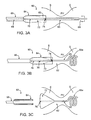
- FIGS. 3A-3C are side views of a distal end of a medical device delivery catheter having a pod and a retractable inner shaft, the figures illustrating a method of medical device delivery, according to one embodiment of the present invention.
- FIG. 4 is a side view of a distal end of a medical device delivery catheter having a pod with a stepped diameter, according to one embodiment of the present invention.
- FIG. 5 is a side view of a distal end of a medical device delivery catheter having a pod with reinforcing side-wall members, according to one embodiment of the present invention.
- FIG. 6 is a perspective view of a portion of a material for forming a pod, illustrating one method for coupling edges of the pod material together, according to one embodiment of the present invention.
- FIGS. 7A-7C are side views of a peel-away distal pod of a medical device delivery catheter, illustrating a method for peeling the pod, according to one embodiment of the present invention.
- a medical device delivery catheter may be used to delivery any of a number of medical devices in any of a number of locations in a human body.
- one embodiment may be used to deliver stents in an a coronary artery
- another embodiment may deliver stents in peripheral blood vessels
- other embodiments may be used to deliver various devices within the heart
- orthopedic embodiments may be used to deliver devices within various joints, and the like.
- various embodiments of a medical device delivery catheter are adapted for delivering a device in a patient's stomach, with the device in some cases crossing the pyloric valve and extending into the duodenum. Examples of such devices are described in U.S. patent application Ser. Nos.
- a medical device delivery catheter 10 includes a catheter body 12 with a peel-away pod 14 at its distal end.
- a medical device 18 in this embodiment a device for placing in a stomach, is housed within peel-away pod 14 .
- Peel-away pod 14 includes perforations 20 and a cutter 22 .
- a pull cord 24 is attached to cutter 22 and extends through catheter body 12 to exit proximally and attach to a pull ring 25 . Pulling proximally on pull ring 25 causes cutter 22 to move proximally along perforations 20 , thus opening peel-away pod 14 to release medical device 18 .
- peel-away pod 14 may cover all or only part of medical device 18 during delivery.
- Pod 14 may generally be made of any of a number of different materials or combinations of materials.
- peel-away pod 14 is made of a resilient or elastomeric material that is positioned, sometimes stretched, over medical device 18 .
- Such resilient materials may include, for example, silicone, polyisoprene, polyimide, polyurethane, polyolefin or the like.
- peel-away pod 14 may be made of a rigid material such as but not limited to polyethylene, nylon, stainless steel, nitinol, ceramic, Teflon or a composite material, with perforations 20 , slits, holes or the like allowing pod 14 to break or tear apart.
- Perforations 20 extend along the entire length of pod 14 or only part of pod 14 . They may also be disposed along pod 14 in any suitable configuration or pattern, such as in one or more longitudinal lines, one or more circumferential lines, one or more spiral lines, an open mouth configuration, irregular or asymmetrical patterns, or the like. In yet other embodiments, one or more lines of structural weakness, other than perforations 20 , may be built into peel-away pod 14 , such as lines of thinner or structurally weaker material, a non-reinforced portion of a pod 14 that is reinforced elsewhere via fibers, bands or the like, or a combination of non-homogeneous materials.
- pod 14 may be made of a biodegradable material adapted to dissolve upon positioning within the desired delivery location, thus releasing medical device 18 .
- pod 14 may be made of a material designed to rapidly dissolve within the environment of the stomach. Examples of such biodegradable materials include, but are not limited to, gelatin, wax, starch, lactic acid, sugars, proteins, gum and polyvinyl alcohol.
- Some non-degradable pods 14 may be made of shape-memory or super-elastic material such that they curl or fold inward after they are torn or peeled open to release medical device 18 . Curling over edges of pod 14 may help prevent damaging contact with tissues during extraction of delivery device 10 .
- a pod material 26 may have multiple apertures 30 in opposite edges 26 a , 26 b , such that material 26 may be wrapped around a medical device (not shown) and the edges 26 a , 26 b may be attached via a cord 30 .
- cord shall mean any cord, wire, thread, filament, string or the like.
- Cord 30 is wound through apertures 28 to hold the two edges 26 a , 26 b of material 26 together, thus constraining medical device 18 within material 26 .
- Cord 30 may then be withdrawn (solid-tipped arrow) to the edges 26 a , 26 b , thus allowing material 26 to open, and thus releasing the medical device.
- cord 30 may be sewn through apertures 28 or perforations or wrapped or looped around apertures 28 or perforations.
- any suitable cutter 22 or other actuator device for cutting or beginning a tear in peel-away pod 14 may be used.
- cutter 22 may be a blade, cord, wedge, or the like.
- part of medical device 18 itself may act as cutter 22 , with that part of medical device 18 being retracted or advanced in such a way as to cut pod 14 .
- a zipper may be used to unzip peel-away pod 14 .
- perforations 20 are replaced with a zip-lock device, which is unzipped to open pod 14 .
- Cutter 22 is attached to pull cord 24 , which extends from cutter 22 through catheter body 12 to exit proximally and attach to pull ring 25 .
- pull ring 25 may be replaced with any other actuator devices, such as but not limited to a slide, trigger, button or the like. Pulling proximally on pull ring 25 moved cutter 22 proximally along perforations 20 , thus cutting (or “peeling”) pod 14 open to release medical device 18 .
- Pod 14 may include any of a number of different distal end configurations.
- peel-away pod 14 has an open distal end, and medical device 18 protrudes out of the distal end to form a blunt tip.
- pod 14 may include a blunt tip that completely surrounds medical device 18 .
- a tip of pod 14 may be flexible, to help facilitate advancement along a guidewire through a tortuous anatomical path.
- peel-away pod 14 may include a sharp or pointed tip to facilitate piercing through tissue, for example to facilitate piercing through tough connective tissue to deliver device 18 into a joint space.
- a medical device delivery catheter 40 suitably includes a catheter body 58 and a pod 41 , with pod 41 being adapted to house medical device 18 .
- Pod 41 generally includes two opposed housing members 42 , movably coupled at their proximal ends by a hinge 56 to enable pod 41 to open like a clam shell ( FIG. 2B ).
- Attached to one of housing members 42 is a guidewire tube 44 to allow catheter 40 to be advanced over a guidewire 46 .
- a ring 48 Disposed over the distal end of pod 41 in FIG. 2A is a ring 48 , coupled with a pull cord 50 .
- a movable inner shaft 54 extends through catheter body 58 and is attached distally to a platform 52 for helping push medical device 18 out of the opened pod 41 ( FIG. 2B ).
- catheter 40 may include a number of variations.
- guidewire tube 44 in some embodiments, may be positioned on the inside of pod 41 , may extend onto catheter body 58 or may be disposed entirely on catheter body 58 and not on pod 41 .
- pull cord 50 may be disposed inside pod 41 and catheter body 58 in some embodiments.
- Inner shaft 54 and platform 52 are optional features, which are not necessarily included in all embodiments.
- platform 52 is attached via a spring to the proximal end of the inside of pod 41 , such that platform 52 is spring-loaded and automatically springs forward upon release of medical device 18 from pod 41 . Any suitable hinge 56 , or multiple hinges, may be substituted.
- pod 41 may open by curving outward due to shape-memory or spring-loaded materials rather than via a hinge.
- Other closure devices may also be substituted for ring 48 , such as a closure sleeve, pin, movable clamp or the like.
- Housings 42 may be either rigid or flexible and may be made of any suitable material or combination of materials.
- the outer diameter of pod 41 is greater than the outer diameter of catheter body 58 , as in FIGS. 2A and 2B .
- the outer diameters may be the same.
- various embodiments of medical device delivery catheter 40 may have any of a number of different configurations and features, without departing from the scope of the present invention.
- delivery catheter 40 is positioned in a desired location for delivering medical device 18 , such as in the stomach and possibly extending across the pyloric valve into the duodenum. Advancement to a desired location may be facilitated by incorporating one or more radiopaque markers or materials into catheter 40 and/or by including one or more depth markings on the outer surface of a proximal portion of catheter body 58 to help the user determine how far catheter 40 has been advanced into the body.
- pull cord 50 is pulled proximally by a user at the proximal end of catheter 40 , thus causing ring to move proximally down pod 41 (solid-tipped arrows).
- Medical device 18 is constrained in a compressed configuration within pod 41 , such that when ring 48 is moved proximally ( FIG. 2B ), medical device 18 springs/expands into an unconstrained, expanded configuration, thus pushing apart housing members 42 , which separate easily due to hinge 56 . Medical device 18 is thus released from pod 41 .
- inner shaft 54 may be advanced by the user to push medical device 18 forward with platform 52 .
- medical device 18 may be placed such that a distal portion 21 resides within the duodenum, a connection portion 19 resides across the pyloric valve, and a proximal portion 17 resides within the stomach.
- the distal portion 21 and proximal portion 17 are typically the expandable portions constrained within pod 41 when it is closed and that push pod 41 open when ring 48 or other constraining device is removed. Once medical device 18 is released, housing members 42 close naturally as delivery catheter 40 is withdrawn from the body.
- a medical device delivery catheter 60 suitably includes a catheter body 66 , a pod 64 attached to the distal end of catheter body 66 , and a retractable inner shaft 68 , extending through catheter body 66 and pod 64 , and beyond the distal end of pod 64 .
- Pod 64 includes a perforated line 70 and a cutter 74 .
- Medical device 62 in this embodiment, includes an expandable proximal portion 72 , and a distal portion 65 , which includes a shape memory distal end 65 .
- proximal portion 72 includes a central lumen 76 , through which inner shaft 68 may pass.
- delivery catheter 60 is positioned such that pod 64 resides within a patient's stomach S and inner shaft 68 with distal portion 65 of medical device 62 extends at least partially across the pyloric valve PV, and sometimes into the duodenum D, as shown.
- catheter 60 and device 62 are in a desired location for deployment, which may be confirmed with one or more radiopaque marking on catheter 60 and/or device 62 , and/or with depth markings on the outer surface of catheter body 66 , inner shaft is retracted 68 (solid-tipped arrows). As illustrated in FIG.
- shape memory distal end 65 a deforms from its straight, undeployed shape to its deployed shape, which in this case is a helical shape.
- Other shapes such as a round or elliptical ball-like shape, an hourglass shape, a curled snail-like shape or the like may be used in alternative embodiments.
- Distal end 65 a may suitably be made of any shape-memory, super-elastic material, spring-loaded, or other resilient material to allow it to move from the undeployed to deployed configuration.
- distal end 65 a in its deployed configuration is designed to reside within a proximal portion of the duodenum D and to prevent its passage through the pyloric valve PV, back into the stomach S.
- proximal portion 72 of medical device 62 is cut (or torn, split or peeled, in various embodiments) along perforated line 70 , using cutter 74 .
- proximal portion 72 expands upon release from pod 64 , thus assuming its deployed, expanded configuration, which causes it to remain in the stomach S and prevents it from crossing the pyloric valve PV into the duodenum D.
- Rotational orientation of medical device 62 about the long axis of catheter 60 may often be important to achieve a desired delivery.
- the orientation of perforated line 70 and thus the side on which pod 64 opens, is configured to achieve a desired, and controlled, rotational orientation of medical device 62 upon delivery. Delivery catheter 60 may then be withdrawn, leaving medical device 62 in place within the stomach S, crossing the pyloric valve PV into the duodenum D.
- Various embodiments of delivery catheter 60 may include additional features to enhance and/or facilitate delivery of medical device 62 .
- rotational orientation of inner shaft 68 with respect to medical device 62 may be controlled in some embodiments 15 by “keying” device 62 to shaft 68 .
- the keying function may be achieved by providing catheter 60 with a non-circular lumen (e-g., square, triangle, slot, etc.) keyed to a non-circular cross-sectional shape of device 62 .
- device 62 may engage shaft 68 via a keyed anchor disposed along the length of device 62 (or in multiple locations).
- an anchor is cast in the distal tip of device 62 .
- the anchor may have a slot in which shaft 68 engages.
- shaft 68 may also include one or more shape-memory or super-elastic materials, to counteract the restorative forces of medical device 62 in its constrained configuration.
- a medical device delivery catheter 80 includes a catheter body 86 and a pod 82 , which includes a wider proximal portion 82 a , a narrower distal portion 82 b , and a step-off 84 between the two.
- Pod 82 may open via perforations 88 , or, in alternative embodiment, any other suitable means as described above.
- Distal portion 82 b is configured and sized such that it can be advanced through the pyloric valve PV to position its distal end in the duodenum D.
- Step-off 84 is configured and sized such that it will not move through the pyloric valve PV.
- pod 82 is configured to allow a user to advance delivery catheter 80 partially through the pyloric valve to release a medical device 81 in a location spanning the valve.
- step-off 84 bumps up against the pyloric valve PV, such that the user can feel the abutment and knows catheter 80 is sufficiently advanced.
- Medical device 81 is then deployed in the desired location spanning the valve.
- the medical device itself rather than the pod, includes a step-off in diameter to allow partial, but not complete, passage through the pyloric valve PV.
- medical device delivery catheter 90 includes a catheter body 94 and a pod 92 having one or more support members 96 disposed along its inner wall and one or more sets of perforations 98 .
- Support members 96 may be elongate, curved, horseshoe-shaped or otherwise configured pieces of silicone molded or attached to the wall via adhesive.
- support members 96 may be attached with stitching or case into pod 92 .
- support members 96 may be biodegradable.
- Support members 96 are generally configured to help stabilize pod 92 and prevent it from kinking or bending in an area in which a narrower portion of a medical device 91 is disposed.
- support members 96 may be embedded in the wall of pod 92 , and may include other materials such as metal.
- FIGS. 7A-7C another embodiment of a medical device delivery catheter 100 is shown, and a method for opening a pod 102 is illustrated.
- Pod 102 includes two sets of perforations 104 , and a cord 106 extends along pod 102 and is attached at its distal end via an attachment member 108 .
- cord 106 is pulled proximally (solid-tipped arrow), a portion of pod 102 peels away, as shown in FIG. 7B , thus exposing the interior 109 of pod 102 .
- a medical device (not shown) is housed in interior 109 and is thus released when pod 102 is peeled.
- pod 102 peels open further, as in FIG. 7C .
- pod 102 may have any of a number of various perforations, slits, holes, thin material portions or the like to allow for peeling, tearing, cutting or other means for opening pod 102 .
Abstract
Description
Claims (8)
Priority Applications (2)
| Application Number | Priority Date | Filing Date | Title |
|---|---|---|---|
| US12/049,217 US8070824B2 (en) | 2004-10-26 | 2008-03-14 | Medical device delivery catheter |
| US13/309,434 US8579988B2 (en) | 2004-10-26 | 2011-12-01 | Medical device delivery catheter |
Applications Claiming Priority (2)
| Application Number | Priority Date | Filing Date | Title |
|---|---|---|---|
| US10/974,482 US7347868B2 (en) | 2004-10-26 | 2004-10-26 | Medical device delivery catheter |
| US12/049,217 US8070824B2 (en) | 2004-10-26 | 2008-03-14 | Medical device delivery catheter |
Related Parent Applications (1)
| Application Number | Title | Priority Date | Filing Date |
|---|---|---|---|
| US10/974,482 Continuation US7347868B2 (en) | 2004-10-26 | 2004-10-26 | Medical device delivery catheter |
Related Child Applications (1)
| Application Number | Title | Priority Date | Filing Date |
|---|---|---|---|
| US13/309,434 Continuation US8579988B2 (en) | 2004-10-26 | 2011-12-01 | Medical device delivery catheter |
Publications (2)
| Publication Number | Publication Date |
|---|---|
| US20080215130A1 US20080215130A1 (en) | 2008-09-04 |
| US8070824B2 true US8070824B2 (en) | 2011-12-06 |
Family
ID=36207071
Family Applications (3)
| Application Number | Title | Priority Date | Filing Date |
|---|---|---|---|
| US10/974,482 Active 2026-02-24 US7347868B2 (en) | 2004-10-26 | 2004-10-26 | Medical device delivery catheter |
| US12/049,217 Expired - Fee Related US8070824B2 (en) | 2004-10-26 | 2008-03-14 | Medical device delivery catheter |
| US13/309,434 Active US8579988B2 (en) | 2004-10-26 | 2011-12-01 | Medical device delivery catheter |
Family Applications Before (1)
| Application Number | Title | Priority Date | Filing Date |
|---|---|---|---|
| US10/974,482 Active 2026-02-24 US7347868B2 (en) | 2004-10-26 | 2004-10-26 | Medical device delivery catheter |
Family Applications After (1)
| Application Number | Title | Priority Date | Filing Date |
|---|---|---|---|
| US13/309,434 Active US8579988B2 (en) | 2004-10-26 | 2011-12-01 | Medical device delivery catheter |
Country Status (6)
| Country | Link |
|---|---|
| US (3) | US7347868B2 (en) |
| EP (1) | EP1804678A4 (en) |
| JP (1) | JP2008517677A (en) |
| AU (1) | AU2005299614B2 (en) |
| CA (1) | CA2585430A1 (en) |
| WO (1) | WO2006047708A2 (en) |
Cited By (15)
| Publication number | Priority date | Publication date | Assignee | Title |
|---|---|---|---|---|
| US9526648B2 (en) | 2010-06-13 | 2016-12-27 | Synerz Medical, Inc. | Intragastric device for treating obesity |
| US9730822B2 (en) | 2014-04-30 | 2017-08-15 | Lean Medical Technologies, LLC | Gastrointestinal device |
| US9956393B2 (en) | 2015-02-24 | 2018-05-01 | Elira, Inc. | Systems for increasing a delay in the gastric emptying time for a patient using a transcutaneous electro-dermal patch |
| US10118035B2 (en) | 2015-02-24 | 2018-11-06 | Elira, Inc. | Systems and methods for enabling appetite modulation and/or improving dietary compliance using an electro-dermal patch |
| US10335302B2 (en) | 2015-02-24 | 2019-07-02 | Elira, Inc. | Systems and methods for using transcutaneous electrical stimulation to enable dietary interventions |
| US10376145B2 (en) | 2015-02-24 | 2019-08-13 | Elira, Inc. | Systems and methods for enabling a patient to achieve a weight loss objective using an electrical dermal patch |
| US10413436B2 (en) | 2010-06-13 | 2019-09-17 | W. L. Gore & Associates, Inc. | Intragastric device for treating obesity |
| US10420665B2 (en) | 2010-06-13 | 2019-09-24 | W. L. Gore & Associates, Inc. | Intragastric device for treating obesity |
| US10569063B2 (en) | 2014-10-03 | 2020-02-25 | W. L. Gore & Associates, Inc. | Removable covers for drug eluting medical devices |
| US10765863B2 (en) | 2015-02-24 | 2020-09-08 | Elira, Inc. | Systems and methods for using a transcutaneous electrical stimulation device to deliver titrated therapy |
| US10779980B2 (en) | 2016-04-27 | 2020-09-22 | Synerz Medical, Inc. | Intragastric device for treating obesity |
| US10864367B2 (en) | 2015-02-24 | 2020-12-15 | Elira, Inc. | Methods for using an electrical dermal patch in a manner that reduces adverse patient reactions |
| US11096774B2 (en) | 2016-12-09 | 2021-08-24 | Zenflow, Inc. | Systems, devices, and methods for the accurate deployment of an implant in the prostatic urethra |
| US11135078B2 (en) | 2010-06-13 | 2021-10-05 | Synerz Medical, Inc. | Intragastric device for treating obesity |
| US11890213B2 (en) | 2019-11-19 | 2024-02-06 | Zenflow, Inc. | Systems, devices, and methods for the accurate deployment and imaging of an implant in the prostatic urethra |
Families Citing this family (148)
| Publication number | Priority date | Publication date | Assignee | Title |
|---|---|---|---|---|
| US6746483B1 (en) * | 2000-03-16 | 2004-06-08 | Smith & Nephew, Inc. | Sheaths for implantable fixation devices |
| US9060844B2 (en) | 2002-11-01 | 2015-06-23 | Valentx, Inc. | Apparatus and methods for treatment of morbid obesity |
| WO2005067817A1 (en) * | 2004-01-13 | 2005-07-28 | Remon Medical Technologies Ltd | Devices for fixing a sensor in a body lumen |
| US7559925B2 (en) | 2006-09-15 | 2009-07-14 | Acclarent Inc. | Methods and devices for facilitating visualization in a surgical environment |
| US10188413B1 (en) | 2004-04-21 | 2019-01-29 | Acclarent, Inc. | Deflectable guide catheters and related methods |
| US9351750B2 (en) * | 2004-04-21 | 2016-05-31 | Acclarent, Inc. | Devices and methods for treating maxillary sinus disease |
| US8764729B2 (en) | 2004-04-21 | 2014-07-01 | Acclarent, Inc. | Frontal sinus spacer |
| US9089258B2 (en) | 2004-04-21 | 2015-07-28 | Acclarent, Inc. | Endoscopic methods and devices for transnasal procedures |
| US8702626B1 (en) | 2004-04-21 | 2014-04-22 | Acclarent, Inc. | Guidewires for performing image guided procedures |
| US8864787B2 (en) * | 2004-04-21 | 2014-10-21 | Acclarent, Inc. | Ethmoidotomy system and implantable spacer devices having therapeutic substance delivery capability for treatment of paranasal sinusitis |
| US7654997B2 (en) | 2004-04-21 | 2010-02-02 | Acclarent, Inc. | Devices, systems and methods for diagnosing and treating sinusitus and other disorders of the ears, nose and/or throat |
| US20190314620A1 (en) | 2004-04-21 | 2019-10-17 | Acclarent, Inc. | Apparatus and methods for dilating and modifying ostia of paranasal sinuses and other intranasal or paranasal structures |
| US8932276B1 (en) | 2004-04-21 | 2015-01-13 | Acclarent, Inc. | Shapeable guide catheters and related methods |
| US20070167682A1 (en) | 2004-04-21 | 2007-07-19 | Acclarent, Inc. | Endoscopic methods and devices for transnasal procedures |
| US8747389B2 (en) | 2004-04-21 | 2014-06-10 | Acclarent, Inc. | Systems for treating disorders of the ear, nose and throat |
| US7803150B2 (en) | 2004-04-21 | 2010-09-28 | Acclarent, Inc. | Devices, systems and methods useable for treating sinusitis |
| US7462175B2 (en) | 2004-04-21 | 2008-12-09 | Acclarent, Inc. | Devices, systems and methods for treating disorders of the ear, nose and throat |
| US20060063973A1 (en) | 2004-04-21 | 2006-03-23 | Acclarent, Inc. | Methods and apparatus for treating disorders of the ear, nose and throat |
| US20070208252A1 (en) * | 2004-04-21 | 2007-09-06 | Acclarent, Inc. | Systems and methods for performing image guided procedures within the ear, nose, throat and paranasal sinuses |
| US7419497B2 (en) | 2004-04-21 | 2008-09-02 | Acclarent, Inc. | Methods for treating ethmoid disease |
| US8894614B2 (en) | 2004-04-21 | 2014-11-25 | Acclarent, Inc. | Devices, systems and methods useable for treating frontal sinusitis |
| US9554691B2 (en) | 2004-04-21 | 2017-01-31 | Acclarent, Inc. | Endoscopic methods and devices for transnasal procedures |
| US20060004323A1 (en) | 2004-04-21 | 2006-01-05 | Exploramed Nc1, Inc. | Apparatus and methods for dilating and modifying ostia of paranasal sinuses and other intranasal or paranasal structures |
| US9399121B2 (en) | 2004-04-21 | 2016-07-26 | Acclarent, Inc. | Systems and methods for transnasal dilation of passageways in the ear, nose or throat |
| WO2005110280A2 (en) | 2004-05-07 | 2005-11-24 | Valentx, Inc. | Devices and methods for attaching an endolumenal gastrointestinal implant |
| US7347868B2 (en) | 2004-10-26 | 2008-03-25 | Baronova, Inc. | Medical device delivery catheter |
| US20060122522A1 (en) * | 2004-12-03 | 2006-06-08 | Abhi Chavan | Devices and methods for positioning and anchoring implantable sensor devices |
| US20060142731A1 (en) * | 2004-12-27 | 2006-06-29 | Jeffrey Brooks | Floating gastro-intestinal anchor |
| WO2014082044A1 (en) | 2012-11-26 | 2014-05-30 | Spatz Fgia, Inc. | System and methods for internalization of components of an adjustable intragastric balloon |
| US9974680B2 (en) | 2004-12-27 | 2018-05-22 | Spatz Fgia, Inc. | System and methods for internalization of external components of adjustable intragastric balloon |
| US8403952B2 (en) * | 2004-12-27 | 2013-03-26 | Spatz-Fgia, Inc. | Floating gastrointestinal anchor |
| US10390714B2 (en) | 2005-01-12 | 2019-08-27 | Remon Medical Technologies, Ltd. | Devices for fixing a sensor in a lumen |
| US8951225B2 (en) | 2005-06-10 | 2015-02-10 | Acclarent, Inc. | Catheters with non-removable guide members useable for treatment of sinusitis |
| US7816975B2 (en) * | 2005-09-20 | 2010-10-19 | Hewlett-Packard Development Company, L.P. | Circuit and method for bias voltage generation |
| US8060214B2 (en) * | 2006-01-05 | 2011-11-15 | Cardiac Pacemakers, Inc. | Implantable medical device with inductive coil configurable for mechanical fixation |
| ES2592316T3 (en) | 2006-03-28 | 2016-11-29 | Spatz-Fgia Inc | Floating gastrointestinal anchor |
| US20070250012A1 (en) * | 2006-04-24 | 2007-10-25 | Ifung Lu | Medical instrument having a medical needle-knife |
| US9138250B2 (en) * | 2006-04-24 | 2015-09-22 | Ethicon Endo-Surgery, Inc. | Medical instrument handle and medical instrument having a handle |
| US8211114B2 (en) | 2006-04-24 | 2012-07-03 | Ethicon Endo-Surgery, Inc. | Medical instrument having a medical snare |
| US7927327B2 (en) * | 2006-04-25 | 2011-04-19 | Ethicon Endo-Surgery, Inc. | Medical instrument having an articulatable end effector |
| US7837620B2 (en) | 2006-04-25 | 2010-11-23 | Ethicon Endo-Surgery, Inc. | Medical tubular assembly |
| US20070255312A1 (en) * | 2006-05-01 | 2007-11-01 | Ifung Lu | Medical instrument having an end-effector-associated member |
| US7758593B2 (en) * | 2006-05-04 | 2010-07-20 | Ethicon Endo-Surgery, Inc. | Medical instrument handle and medical instrument having same |
| US7597661B2 (en) * | 2006-05-11 | 2009-10-06 | Ethicon Endo-Surgery, Inc. | Medical instrument having a catheter and method for using a catheter |
| US7959642B2 (en) * | 2006-05-16 | 2011-06-14 | Ethicon Endo-Surgery, Inc. | Medical instrument having a needle knife |
| US20070270639A1 (en) * | 2006-05-17 | 2007-11-22 | Long Gary L | Medical instrument having a catheter and having a catheter accessory device and method for using |
| US7892166B2 (en) * | 2006-05-18 | 2011-02-22 | Ethicon Endo-Surgery, Inc. | Medical instrument including a catheter having a catheter stiffener and method for using |
| US8439961B2 (en) * | 2006-07-31 | 2013-05-14 | Boston Scientific Scimed, Inc. | Stent retaining mechanisms |
| US8676349B2 (en) | 2006-09-15 | 2014-03-18 | Cardiac Pacemakers, Inc. | Mechanism for releasably engaging an implantable medical device for implantation |
| WO2008034077A2 (en) * | 2006-09-15 | 2008-03-20 | Cardiac Pacemakers, Inc. | Anchor for an implantable sensor |
| US20080071248A1 (en) * | 2006-09-15 | 2008-03-20 | Cardiac Pacemakers, Inc. | Delivery stystem for an implantable physiologic sensor |
| WO2008057720A1 (en) * | 2006-11-08 | 2008-05-15 | Cardiac Pacemakers, Inc. | Implant for securing a sensor in a vessel |
| CA2675650A1 (en) * | 2007-02-07 | 2008-08-14 | Duocure, Inc. | Duodenal stimulation devices and methods for the treatment of conditions relating to eating disorders |
| US20100121371A1 (en) * | 2007-04-30 | 2010-05-13 | Spatz Fgia, Inc. | Non-endoscopic insertion and removal of a device |
| US8204599B2 (en) * | 2007-05-02 | 2012-06-19 | Cardiac Pacemakers, Inc. | System for anchoring an implantable sensor in a vessel |
| US20080283066A1 (en) * | 2007-05-17 | 2008-11-20 | Cardiac Pacemakers, Inc. | Delivery device for implantable sensors |
| EP2162185B1 (en) | 2007-06-14 | 2015-07-01 | Cardiac Pacemakers, Inc. | Multi-element acoustic recharging system |
| CA2694459A1 (en) | 2007-07-24 | 2009-01-29 | Betastim, Ltd. | Duodenal eating sensor |
| EP2185084A4 (en) * | 2007-09-07 | 2017-08-09 | Baronova, Inc. | Device for intermittently obstructing a gastric opening and method of use |
| EP2190388B1 (en) * | 2007-10-17 | 2014-03-05 | Angiomed GmbH & Co. Medizintechnik KG | Delivery system for a self-expanding device for placement in a bodily lumen |
| US8915951B2 (en) * | 2008-02-11 | 2014-12-23 | Boston Scientific Scimed, Inc. | Self-expandable stent with a constrictive coating and method of use |
| US8221494B2 (en) | 2008-02-22 | 2012-07-17 | Endologix, Inc. | Apparatus and method of placement of a graft or graft system |
| WO2009122299A2 (en) * | 2008-04-03 | 2009-10-08 | Gardia Medical Ltd. | Delivery catheter with constraining sheath and methods of deploying medical devices into a body lumen |
| US8236040B2 (en) * | 2008-04-11 | 2012-08-07 | Endologix, Inc. | Bifurcated graft deployment systems and methods |
| GB0815339D0 (en) * | 2008-08-21 | 2008-10-01 | Angiomed Ag | Method of loading a stent into a sheath |
| EP2278943B1 (en) * | 2008-05-09 | 2014-03-26 | Angiomed GmbH & Co. Medizintechnik KG | Method of loading a stent into a sheath |
| US8211053B2 (en) | 2008-05-13 | 2012-07-03 | Equilibrate, Llc | Interosmolar fluid removal |
| GB0810749D0 (en) | 2008-06-11 | 2008-07-16 | Angiomed Ag | Catherter delivery device |
| US9750625B2 (en) | 2008-06-11 | 2017-09-05 | C.R. Bard, Inc. | Catheter delivery device |
| WO2010002786A2 (en) * | 2008-06-30 | 2010-01-07 | Rafael Fleites | Method and system for endoscopic placement of a balloon |
| US8934987B2 (en) * | 2008-07-15 | 2015-01-13 | Cardiac Pacemakers, Inc. | Implant assist apparatus for acoustically enabled implantable medical device |
| EP2323724A1 (en) | 2008-09-18 | 2011-05-25 | Acclarent, Inc. | Methods and apparatus for treating disorders of the ear nose and throat |
| GB0823716D0 (en) | 2008-12-31 | 2009-02-04 | Angiomed Ag | Stent delivery device with rolling stent retaining sheath |
| WO2010093489A2 (en) | 2009-02-13 | 2010-08-19 | Cardiac Pacemakers, Inc. | Deployable sensor platform on the lead system of an implantable device |
| DE102009018723A1 (en) * | 2009-04-27 | 2010-10-28 | Karl Storz Gmbh & Co. Kg | Medical dilatation instrument |
| EP2429452B1 (en) | 2009-04-28 | 2020-01-15 | Endologix, Inc. | Endoluminal prosthesis system |
| US20110218608A1 (en) * | 2009-09-10 | 2011-09-08 | Novostent Corporation | Vascular Prosthesis Delivery System and Method |
| GB0921236D0 (en) * | 2009-12-03 | 2010-01-20 | Angiomed Ag | Stent device delivery system and method of making such |
| GB0921237D0 (en) * | 2009-12-03 | 2010-01-20 | Angiomed Ag | Stent device delivery system and method of making such |
| GB0921240D0 (en) * | 2009-12-03 | 2010-01-20 | Angiomed Ag | Stent device delivery system and method of making such |
| GB0921238D0 (en) | 2009-12-03 | 2010-01-20 | Angiomed Ag | Stent device delivery system and method of making such |
| US8870950B2 (en) | 2009-12-08 | 2014-10-28 | Mitral Tech Ltd. | Rotation-based anchoring of an implant |
| US20110184509A1 (en) * | 2010-01-27 | 2011-07-28 | Abbott Laboratories | Dual sheath assembly and method of use |
| US20110208292A1 (en) * | 2010-02-19 | 2011-08-25 | Abbott Laboratories | Hinged sheath assembly and method of use |
| US20110224785A1 (en) | 2010-03-10 | 2011-09-15 | Hacohen Gil | Prosthetic mitral valve with tissue anchors |
| US11653910B2 (en) | 2010-07-21 | 2023-05-23 | Cardiovalve Ltd. | Helical anchor implantation |
| US9763657B2 (en) | 2010-07-21 | 2017-09-19 | Mitraltech Ltd. | Techniques for percutaneous mitral valve replacement and sealing |
| US9198791B2 (en) | 2010-07-22 | 2015-12-01 | Endobetix Ltd. | Pancreaticobiliary diversion device |
| US10111767B2 (en) | 2010-10-29 | 2018-10-30 | Abbott Cardiovascular Systems Inc. | Sheaths used in polymer scaffold delivery systems |
| US20120109279A1 (en) | 2010-11-02 | 2012-05-03 | Endologix, Inc. | Apparatus and method of placement of a graft or graft system |
| GB201020373D0 (en) | 2010-12-01 | 2011-01-12 | Angiomed Ag | Device to release a self-expanding implant |
| US20120172887A1 (en) | 2011-01-05 | 2012-07-05 | Wilson-Cook Medical, Inc. d/b/a Cook Endoscopy | Proximal Release Expandable Prosthesis Delivery System |
| US8414528B2 (en) | 2011-05-27 | 2013-04-09 | Abbott Cardiovascular Systems Inc. | Polymer scaffold sheaths |
| US8852257B2 (en) | 2011-06-21 | 2014-10-07 | Abbott Cardiovascular Systems Inc. | Sheaths used with polymer scaffold |
| US8852272B2 (en) | 2011-08-05 | 2014-10-07 | Mitraltech Ltd. | Techniques for percutaneous mitral valve replacement and sealing |
| WO2013021375A2 (en) | 2011-08-05 | 2013-02-14 | Mitraltech Ltd. | Percutaneous mitral valve replacement and sealing |
| WO2013021374A2 (en) | 2011-08-05 | 2013-02-14 | Mitraltech Ltd. | Techniques for percutaneous mitral valve replacement and sealing |
| US20140324164A1 (en) * | 2011-08-05 | 2014-10-30 | Mitraltech Ltd. | Techniques for percutaneous mitral valve replacement and sealing |
| US10213329B2 (en) | 2011-08-12 | 2019-02-26 | W. L. Gore & Associates, Inc. | Evertable sheath devices, systems, and methods |
| US9011514B2 (en) * | 2011-08-22 | 2015-04-21 | Cook Medical Technologies Llc | Emergency vessel repair prosthesis deployment system |
| US9089399B2 (en) * | 2011-09-17 | 2015-07-28 | Katalyst Surgical, Llc | Steerable laser probe |
| US9168352B2 (en) | 2011-12-19 | 2015-10-27 | Cardiacassist, Inc. | Dual lumen cannula |
| US9681975B2 (en) | 2012-05-31 | 2017-06-20 | Valentx, Inc. | Devices and methods for gastrointestinal bypass |
| US9050168B2 (en) | 2012-05-31 | 2015-06-09 | Valentx, Inc. | Devices and methods for gastrointestinal bypass |
| US9451960B2 (en) | 2012-05-31 | 2016-09-27 | Valentx, Inc. | Devices and methods for gastrointestinal bypass |
| US8628571B1 (en) | 2012-11-13 | 2014-01-14 | Mitraltech Ltd. | Percutaneously-deliverable mechanical valve |
| US9072590B2 (en) | 2012-12-07 | 2015-07-07 | Abbott Cardiovascular Systems Inc. | Sheaths reducing recoil and loss of retention for polymer scaffolds crimped to balloons |
| EP2948103B1 (en) | 2013-01-24 | 2022-12-07 | Cardiovalve Ltd | Ventricularly-anchored prosthetic valves |
| AU2014218701A1 (en) * | 2013-02-21 | 2015-09-10 | Xlumena, Inc. | Devices and methods for forming an anastomosis |
| US9763819B1 (en) | 2013-03-05 | 2017-09-19 | W. L. Gore & Associates, Inc. | Tapered sleeve |
| US9757264B2 (en) | 2013-03-13 | 2017-09-12 | Valentx, Inc. | Devices and methods for gastrointestinal bypass |
| US9788983B2 (en) | 2013-06-21 | 2017-10-17 | Abbott Cardiovascular Systems Inc. | Removable sheath assembly for a polymer scaffold |
| US9675483B2 (en) | 2013-06-21 | 2017-06-13 | Abbott Cardiovascular Systems Inc. | Protective sheath assembly for a polymer scaffold |
| US10098771B2 (en) | 2013-09-25 | 2018-10-16 | Abbott Cardiovascular Systems Inc. | Clip sheath for a polymer scaffold |
| US9907641B2 (en) | 2014-01-10 | 2018-03-06 | W. L. Gore & Associates, Inc. | Implantable intraluminal device |
| EP3102122A1 (en) | 2014-02-06 | 2016-12-14 | Boston Scientific Scimed, Inc. | Occlusion device detachable by inflation of a balloon |
| US9913958B2 (en) | 2014-02-28 | 2018-03-13 | Abbott Cardiovascular Systems Inc. | Protective sheaths for medical devices |
| US10966850B2 (en) * | 2014-03-06 | 2021-04-06 | W. L. Gore & Associates, Inc. | Implantable medical device constraint and deployment apparatus |
| US9364361B2 (en) | 2014-03-13 | 2016-06-14 | Abbott Cardiovascular Systems Inc. | Striped sheaths for medical devices |
| US9510976B2 (en) * | 2014-04-29 | 2016-12-06 | Abbott Cardiovascular Systems Inc. | Devices and methods for treatment of the Eustachian tube and sinus cavity |
| US9414947B2 (en) * | 2014-05-13 | 2016-08-16 | Covidien Lp | Gastric tubes having tethered plugs and methods of use |
| EP3174502B1 (en) | 2014-07-30 | 2022-04-06 | Cardiovalve Ltd | Apparatus for implantation of an articulatable prosthetic valve |
| US9974651B2 (en) | 2015-02-05 | 2018-05-22 | Mitral Tech Ltd. | Prosthetic valve with axially-sliding frames |
| EP3253333B1 (en) | 2015-02-05 | 2024-04-03 | Cardiovalve Ltd | Prosthetic valve with axially-sliding frames |
| US9757574B2 (en) | 2015-05-11 | 2017-09-12 | Rainbow Medical Ltd. | Dual chamber transvenous pacemaker |
| US11129737B2 (en) | 2015-06-30 | 2021-09-28 | Endologix Llc | Locking assembly for coupling guidewire to delivery system |
| US10531866B2 (en) | 2016-02-16 | 2020-01-14 | Cardiovalve Ltd. | Techniques for providing a replacement valve and transseptal communication |
| USD800908S1 (en) | 2016-08-10 | 2017-10-24 | Mitraltech Ltd. | Prosthetic valve element |
| WO2018029680A1 (en) | 2016-08-10 | 2018-02-15 | Mitraltech Ltd. | Prosthetic valve with concentric frames |
| US11426276B2 (en) * | 2016-10-12 | 2022-08-30 | Medtronic Vascular, Inc. | Stented prosthetic heart valve delivery system having an expandable bumper |
| JP2018126221A (en) * | 2017-02-06 | 2018-08-16 | 川澄化学工業株式会社 | Catheter for delivery and device for delivering intravascular retainer |
| WO2018146547A1 (en) | 2017-02-09 | 2018-08-16 | Spatz FGIA Ltd | Check valve with docking station for gastrointestinal balloon |
| JP6949546B2 (en) * | 2017-04-28 | 2021-10-13 | 川澄化学工業株式会社 | Transport catheter and intravascular indwelling device transport device |
| JP7103721B2 (en) * | 2017-06-05 | 2022-07-20 | Sbカワスミ株式会社 | Transport catheter and intravascular indwelling device transport device |
| US10575948B2 (en) | 2017-08-03 | 2020-03-03 | Cardiovalve Ltd. | Prosthetic heart valve |
| US11793633B2 (en) | 2017-08-03 | 2023-10-24 | Cardiovalve Ltd. | Prosthetic heart valve |
| US10888421B2 (en) | 2017-09-19 | 2021-01-12 | Cardiovalve Ltd. | Prosthetic heart valve with pouch |
| US11246704B2 (en) | 2017-08-03 | 2022-02-15 | Cardiovalve Ltd. | Prosthetic heart valve |
| US10537426B2 (en) | 2017-08-03 | 2020-01-21 | Cardiovalve Ltd. | Prosthetic heart valve |
| US10933247B2 (en) * | 2017-08-21 | 2021-03-02 | MRM MedTech, LLC | Lead with integrated features to facilitate extraction and associated methods of extraction |
| US11865334B2 (en) * | 2017-08-21 | 2024-01-09 | MRM MedTech, LLC | Lead with integrated feature including a low friction component to facilitate extraction and associated methods of extraction |
| ES2960532T3 (en) | 2017-10-11 | 2024-03-05 | Gore & Ass | Implantable medical device restraint and deployment apparatus |
| GB201720803D0 (en) | 2017-12-13 | 2018-01-24 | Mitraltech Ltd | Prosthetic Valve and delivery tool therefor |
| GB201800399D0 (en) | 2018-01-10 | 2018-02-21 | Mitraltech Ltd | Temperature-control during crimping of an implant |
| US20200129164A1 (en) * | 2018-10-24 | 2020-04-30 | M-V Arterica AB | Self-expanding hemostatic devices and methods for fascia and vessel passages |
| WO2021102044A1 (en) | 2019-11-19 | 2021-05-27 | Arterica Inc. | Vascular closure devices and methods |
| JP2023519174A (en) * | 2020-03-10 | 2023-05-10 | ボストン サイエンティフィック サイムド,インコーポレイテッド | Method for connecting device elements and related devices having such elements |
| CN111904677B (en) * | 2020-09-14 | 2021-06-01 | 艾柯医疗器械(北京)有限公司 | Stent delivery member, stent delivery system, and stent system |
Citations (27)
| Publication number | Priority date | Publication date | Assignee | Title |
|---|---|---|---|---|
| US5222970A (en) | 1991-09-06 | 1993-06-29 | William A. Cook Australia Pty. Ltd. | Method of and system for mounting a vascular occlusion balloon on a delivery catheter |
| US5423872A (en) | 1992-05-29 | 1995-06-13 | Cigaina; Valerio | Process and device for treating obesity and syndromes related to motor disorders of the stomach of a patient |
| US5765682A (en) * | 1994-10-13 | 1998-06-16 | Menlo Care, Inc. | Restrictive package for expandable or shape memory medical devices and method of preventing premature change of same |
| US5820584A (en) | 1997-08-28 | 1998-10-13 | Crabb; Jerry A. | Duodenal insert and method of use |
| US5824041A (en) | 1994-06-08 | 1998-10-20 | Medtronic, Inc. | Apparatus and methods for placement and repositioning of intraluminal prostheses |
| US5895410A (en) | 1997-09-12 | 1999-04-20 | B. Braun Medical, Inc. | Introducer for an expandable vascular occlusion device |
| US6183520B1 (en) | 1996-08-13 | 2001-02-06 | Galt Laboratories, Inc. | Method of maintaining urinary continence |
| US6409656B1 (en) | 1997-10-15 | 2002-06-25 | Patrick Sangouard | Artificial sphincter with magnetic control |
| WO2002091961A1 (en) | 2001-05-17 | 2002-11-21 | Wilson-Cook Medical, Inc. | Intragastric device for treating obesity |
| US6488962B1 (en) | 2000-06-20 | 2002-12-03 | Depomed, Inc. | Tablet shapes to enhance gastric retention of swellable controlled-release oral dosage forms |
| US20020188354A1 (en) | 2001-06-12 | 2002-12-12 | Peghini Paolo Lino | Device to treat obesity by obstructing gastric outlet |
| US20030023150A1 (en) | 2001-07-30 | 2003-01-30 | Olympus Optical Co., Ltd. | Capsule-type medical device and medical system |
| US20030040804A1 (en) | 2001-08-27 | 2003-02-27 | Stack Richard S. | Satiation devices and methods |
| US6540789B1 (en) | 2000-06-15 | 2003-04-01 | Scimed Life Systems, Inc. | Method for treating morbid obesity |
| US6544291B2 (en) | 1997-12-09 | 2003-04-08 | Thomas V. Taylor | Sutureless gastroesophageal anti-reflux valve prosthesis and tool for peroral implantation thereof |
| US6558400B2 (en) | 2001-05-30 | 2003-05-06 | Satiety, Inc. | Obesity treatment tools and methods |
| US20030093117A1 (en) | 1999-06-25 | 2003-05-15 | Vahid Saadat | Implantable artificial partition and methods of use |
| US20030109931A1 (en) | 2001-11-09 | 2003-06-12 | Boston Scientific Corporation | Intragastric stent for duodenum bypass |
| US20030109935A1 (en) | 2001-11-09 | 2003-06-12 | Boston Scientific Corporation | Intragastric prosthesis for the treatment of morbid obesity |
| US20030144708A1 (en) | 2002-01-29 | 2003-07-31 | Starkebaum Warren L. | Methods and apparatus for retarding stomach emptying for treatment of eating disorders |
| US20030153806A1 (en) | 2000-08-08 | 2003-08-14 | Ev&M | Active tissue augmentation materials and method |
| US6669719B2 (en) | 1996-12-09 | 2003-12-30 | Microtherapeutics, Inc. | Intracranial stent and method of use |
| US20040117031A1 (en) | 2001-08-27 | 2004-06-17 | Stack Richard S. | Satiation devices and methods |
| US20050033332A1 (en) | 2003-07-28 | 2005-02-10 | Burnett Daniel R. | Pyloric valve corking device and method |
| US20050033331A1 (en) | 2003-07-28 | 2005-02-10 | Polymorfix, Inc., C/O Medventure Associates | Pyloric valve obstructing devices and methods |
| US20050055039A1 (en) | 2003-07-28 | 2005-03-10 | Polymorfix, Inc. | Devices and methods for pyloric anchoring |
| WO2006047708A2 (en) | 2004-10-26 | 2006-05-04 | Baronova, Inc. | Medical device delivery catheter |
Family Cites Families (3)
| Publication number | Priority date | Publication date | Assignee | Title |
|---|---|---|---|---|
| FR2688688A1 (en) * | 1992-03-12 | 1993-09-24 | Richard Thierry | Tool for fitting an autoexpansible endoprosthesis for human or animal tubular organ |
| US5683451A (en) * | 1994-06-08 | 1997-11-04 | Cardiovascular Concepts, Inc. | Apparatus and methods for deployment release of intraluminal prostheses |
| FR2765098A1 (en) * | 1997-06-25 | 1998-12-31 | Jean Noel Bernard | APPLIANCE FOR LAYING AND RECOVERING PARTS SUCH AS ENDOPROTHESES |
-
2004
- 2004-10-26 US US10/974,482 patent/US7347868B2/en active Active
-
2005
- 2005-10-25 WO PCT/US2005/038842 patent/WO2006047708A2/en active Application Filing
- 2005-10-25 AU AU2005299614A patent/AU2005299614B2/en not_active Ceased
- 2005-10-25 EP EP05814120A patent/EP1804678A4/en not_active Withdrawn
- 2005-10-25 CA CA002585430A patent/CA2585430A1/en not_active Abandoned
- 2005-10-25 JP JP2007538197A patent/JP2008517677A/en active Pending
-
2008
- 2008-03-14 US US12/049,217 patent/US8070824B2/en not_active Expired - Fee Related
-
2011
- 2011-12-01 US US13/309,434 patent/US8579988B2/en active Active
Patent Citations (32)
| Publication number | Priority date | Publication date | Assignee | Title |
|---|---|---|---|---|
| US5222970A (en) | 1991-09-06 | 1993-06-29 | William A. Cook Australia Pty. Ltd. | Method of and system for mounting a vascular occlusion balloon on a delivery catheter |
| US5423872A (en) | 1992-05-29 | 1995-06-13 | Cigaina; Valerio | Process and device for treating obesity and syndromes related to motor disorders of the stomach of a patient |
| US5824041A (en) | 1994-06-08 | 1998-10-20 | Medtronic, Inc. | Apparatus and methods for placement and repositioning of intraluminal prostheses |
| US5765682A (en) * | 1994-10-13 | 1998-06-16 | Menlo Care, Inc. | Restrictive package for expandable or shape memory medical devices and method of preventing premature change of same |
| US6183520B1 (en) | 1996-08-13 | 2001-02-06 | Galt Laboratories, Inc. | Method of maintaining urinary continence |
| US6669719B2 (en) | 1996-12-09 | 2003-12-30 | Microtherapeutics, Inc. | Intracranial stent and method of use |
| US5820584A (en) | 1997-08-28 | 1998-10-13 | Crabb; Jerry A. | Duodenal insert and method of use |
| US5895410A (en) | 1997-09-12 | 1999-04-20 | B. Braun Medical, Inc. | Introducer for an expandable vascular occlusion device |
| US6409656B1 (en) | 1997-10-15 | 2002-06-25 | Patrick Sangouard | Artificial sphincter with magnetic control |
| US6544291B2 (en) | 1997-12-09 | 2003-04-08 | Thomas V. Taylor | Sutureless gastroesophageal anti-reflux valve prosthesis and tool for peroral implantation thereof |
| US20030093117A1 (en) | 1999-06-25 | 2003-05-15 | Vahid Saadat | Implantable artificial partition and methods of use |
| US20030158601A1 (en) | 2000-06-15 | 2003-08-21 | Silverman David E. | Method for treating morbid obesity |
| US6540789B1 (en) | 2000-06-15 | 2003-04-01 | Scimed Life Systems, Inc. | Method for treating morbid obesity |
| US6488962B1 (en) | 2000-06-20 | 2002-12-03 | Depomed, Inc. | Tablet shapes to enhance gastric retention of swellable controlled-release oral dosage forms |
| US20030153806A1 (en) | 2000-08-08 | 2003-08-14 | Ev&M | Active tissue augmentation materials and method |
| WO2002091961A1 (en) | 2001-05-17 | 2002-11-21 | Wilson-Cook Medical, Inc. | Intragastric device for treating obesity |
| US20030078611A1 (en) | 2001-05-17 | 2003-04-24 | Kiyoshi Hashiba | Intragastric device for treating obesity |
| US6558400B2 (en) | 2001-05-30 | 2003-05-06 | Satiety, Inc. | Obesity treatment tools and methods |
| US20020188354A1 (en) | 2001-06-12 | 2002-12-12 | Peghini Paolo Lino | Device to treat obesity by obstructing gastric outlet |
| US20030023150A1 (en) | 2001-07-30 | 2003-01-30 | Olympus Optical Co., Ltd. | Capsule-type medical device and medical system |
| WO2003017882A2 (en) | 2001-08-27 | 2003-03-06 | Synecor, Llc | Satiation devices and methods |
| US7111627B2 (en) * | 2001-08-27 | 2006-09-26 | Synecor, Llc | Satiation devices and methods |
| US20040117031A1 (en) | 2001-08-27 | 2004-06-17 | Stack Richard S. | Satiation devices and methods |
| US20030040804A1 (en) | 2001-08-27 | 2003-02-27 | Stack Richard S. | Satiation devices and methods |
| US20030109935A1 (en) | 2001-11-09 | 2003-06-12 | Boston Scientific Corporation | Intragastric prosthesis for the treatment of morbid obesity |
| US20030109931A1 (en) | 2001-11-09 | 2003-06-12 | Boston Scientific Corporation | Intragastric stent for duodenum bypass |
| US20030144708A1 (en) | 2002-01-29 | 2003-07-31 | Starkebaum Warren L. | Methods and apparatus for retarding stomach emptying for treatment of eating disorders |
| US20050033332A1 (en) | 2003-07-28 | 2005-02-10 | Burnett Daniel R. | Pyloric valve corking device and method |
| US20050033331A1 (en) | 2003-07-28 | 2005-02-10 | Polymorfix, Inc., C/O Medventure Associates | Pyloric valve obstructing devices and methods |
| US20050055039A1 (en) | 2003-07-28 | 2005-03-10 | Polymorfix, Inc. | Devices and methods for pyloric anchoring |
| US6994095B2 (en) | 2003-07-28 | 2006-02-07 | Medventure Associates Iv | Pyloric valve corking device and method |
| WO2006047708A2 (en) | 2004-10-26 | 2006-05-04 | Baronova, Inc. | Medical device delivery catheter |
Non-Patent Citations (5)
| Title |
|---|
| Canadian Patent Application No. 2,585,430 filed Oct. 25, 2005 in the name of Baranova, Inc., Office Action mailed Apr. 29, 2011. |
| International Patent Application No. PCT/US2005/038842 filed Oct. 25, 2005 in the name of Baronova, Inc., International Search Report and Written Opinion mailed Apr. 22, 2008. |
| Japanese Patent Application No. 2007-538197 filed Oct. 25, 2005 in the name of Baranova, Inc., Office Action mailed Mar. 3, 2011. |
| U.S. Appl. No. 10/974,482, filed Oct. 26, 2004 in the name of Burnett, Non-final Office Action mailed Sep. 27, 2007. |
| U.S. Appl. No. 10/974,482, filed Oct. 26, 2004 in the name of Burnett, Notice of Allowance mailed Jan. 7, 2008. |
Cited By (27)
| Publication number | Priority date | Publication date | Assignee | Title |
|---|---|---|---|---|
| US10413436B2 (en) | 2010-06-13 | 2019-09-17 | W. L. Gore & Associates, Inc. | Intragastric device for treating obesity |
| US11607329B2 (en) | 2010-06-13 | 2023-03-21 | Synerz Medical, Inc. | Intragastric device for treating obesity |
| US11596538B2 (en) | 2010-06-13 | 2023-03-07 | Synerz Medical, Inc. | Intragastric device for treating obesity |
| US11351050B2 (en) | 2010-06-13 | 2022-06-07 | Synerz Medical, Inc. | Intragastric device for treating obesity |
| US11135078B2 (en) | 2010-06-13 | 2021-10-05 | Synerz Medical, Inc. | Intragastric device for treating obesity |
| US9526648B2 (en) | 2010-06-13 | 2016-12-27 | Synerz Medical, Inc. | Intragastric device for treating obesity |
| US10512557B2 (en) | 2010-06-13 | 2019-12-24 | W. L. Gore & Associates, Inc. | Intragastric device for treating obesity |
| US10420665B2 (en) | 2010-06-13 | 2019-09-24 | W. L. Gore & Associates, Inc. | Intragastric device for treating obesity |
| US10568755B2 (en) | 2014-04-30 | 2020-02-25 | Lean Medical Technologies, Inc. | Gastrointestinal device |
| US9913744B2 (en) | 2014-04-30 | 2018-03-13 | Lean Medical Technologies, Inc. | Gastrointestinal device |
| US9730822B2 (en) | 2014-04-30 | 2017-08-15 | Lean Medical Technologies, LLC | Gastrointestinal device |
| US9744062B2 (en) | 2014-04-30 | 2017-08-29 | Lean Medical Technologies, LLC | Gastrointestinal device |
| US10569063B2 (en) | 2014-10-03 | 2020-02-25 | W. L. Gore & Associates, Inc. | Removable covers for drug eluting medical devices |
| US11679240B2 (en) | 2014-10-03 | 2023-06-20 | W. L. Gore & Associates, Inc. | Removable covers for drug eluting medical devices |
| US11197613B2 (en) | 2015-02-24 | 2021-12-14 | Elira, Inc. | Systems and methods for enabling a patient to achieve a weight loss objective using an electrical dermal patch |
| US10864367B2 (en) | 2015-02-24 | 2020-12-15 | Elira, Inc. | Methods for using an electrical dermal patch in a manner that reduces adverse patient reactions |
| US9956393B2 (en) | 2015-02-24 | 2018-05-01 | Elira, Inc. | Systems for increasing a delay in the gastric emptying time for a patient using a transcutaneous electro-dermal patch |
| US10376145B2 (en) | 2015-02-24 | 2019-08-13 | Elira, Inc. | Systems and methods for enabling a patient to achieve a weight loss objective using an electrical dermal patch |
| US10118035B2 (en) | 2015-02-24 | 2018-11-06 | Elira, Inc. | Systems and methods for enabling appetite modulation and/or improving dietary compliance using an electro-dermal patch |
| US10143840B2 (en) | 2015-02-24 | 2018-12-04 | Elira, Inc. | Systems and methods for enabling appetite modulation and/or improving dietary compliance using an electro-dermal patch |
| US10335302B2 (en) | 2015-02-24 | 2019-07-02 | Elira, Inc. | Systems and methods for using transcutaneous electrical stimulation to enable dietary interventions |
| US10765863B2 (en) | 2015-02-24 | 2020-09-08 | Elira, Inc. | Systems and methods for using a transcutaneous electrical stimulation device to deliver titrated therapy |
| US11712562B2 (en) | 2015-02-24 | 2023-08-01 | Elira, Inc. | Systems and methods for using a transcutaneous electrical stimulation device to deliver titrated therapy |
| US10779980B2 (en) | 2016-04-27 | 2020-09-22 | Synerz Medical, Inc. | Intragastric device for treating obesity |
| US11096774B2 (en) | 2016-12-09 | 2021-08-24 | Zenflow, Inc. | Systems, devices, and methods for the accurate deployment of an implant in the prostatic urethra |
| US11903859B1 (en) | 2016-12-09 | 2024-02-20 | Zenflow, Inc. | Methods for deployment of an implant |
| US11890213B2 (en) | 2019-11-19 | 2024-02-06 | Zenflow, Inc. | Systems, devices, and methods for the accurate deployment and imaging of an implant in the prostatic urethra |
Also Published As
| Publication number | Publication date |
|---|---|
| EP1804678A2 (en) | 2007-07-11 |
| CA2585430A1 (en) | 2006-05-04 |
| US20120165788A1 (en) | 2012-06-28 |
| JP2008517677A (en) | 2008-05-29 |
| WO2006047708A2 (en) | 2006-05-04 |
| WO2006047708A3 (en) | 2009-04-16 |
| AU2005299614B2 (en) | 2011-06-16 |
| US8579988B2 (en) | 2013-11-12 |
| AU2005299614A1 (en) | 2006-05-04 |
| US7347868B2 (en) | 2008-03-25 |
| US20080215130A1 (en) | 2008-09-04 |
| EP1804678A4 (en) | 2010-11-03 |
| US20060089627A1 (en) | 2006-04-27 |
| AU2005299614A8 (en) | 2011-10-13 |
Similar Documents
| Publication | Publication Date | Title |
|---|---|---|
| US8070824B2 (en) | Medical device delivery catheter | |
| CA3088262C (en) | Devices and systems for pyloric occlusion | |
| US10034669B2 (en) | Anastomosis devices and methods | |
| EP1139882B1 (en) | Gerd treatment apparatus | |
| US11737900B2 (en) | Systems and methods for anchoring and restraining gastrointestinal prostheses | |
| US20120245504A1 (en) | Devices and methods to deliver, retain and remove a separating device in an intussuscepted hollow organ | |
| EP3119289B1 (en) | Devices for lumen occlusion | |
| JP6473905B2 (en) | Inverted transfer device and method for prosthesis | |
| US20230074646A1 (en) | Systems and methods for anchoring and restraining gastrointestinal prostheses | |
| WO2018052844A1 (en) | System, device and method for treatment of endometriosis |
Legal Events
| Date | Code | Title | Description |
|---|---|---|---|
| AS | Assignment |
Owner name: BARONOVA, INC., CALIFORNIA Free format text: ASSIGNMENT OF ASSIGNORS INTEREST;ASSIGNOR:MEDVENTURE ASSOCIATES IV;REEL/FRAME:020696/0646 Effective date: 20060524 Owner name: MEDVENTURE ASSOCIATES IV, CALIFORNIA Free format text: ASSIGNMENT OF ASSIGNORS INTEREST;ASSIGNOR:POLYMORFIX, INC.;REEL/FRAME:020696/0629 Effective date: 20051017 Owner name: POLYMORFIX, INC., CALIFORNIA Free format text: ASSIGNMENT OF ASSIGNORS INTEREST;ASSIGNORS:BURNETT, DANIEL R.;HALL, GREGORY W.;BAJOR, JORDAN T.;AND OTHERS;REEL/FRAME:020696/0598 Effective date: 20050126 |
|
| ZAAA | Notice of allowance and fees due |
Free format text: ORIGINAL CODE: NOA |
|
| ZAAB | Notice of allowance mailed |
Free format text: ORIGINAL CODE: MN/=. |
|
| STCF | Information on status: patent grant |
Free format text: PATENTED CASE |
|
| FPAY | Fee payment |
Year of fee payment: 4 |
|
| AS | Assignment |
Owner name: PACIFIC WESTERN BANK, NORTH CAROLINA Free format text: SECURITY INTEREST;ASSIGNOR:BARONOVA, INC.;REEL/FRAME:047626/0955 Effective date: 20181113 |
|
| MAFP | Maintenance fee payment |
Free format text: PAYMENT OF MAINTENANCE FEE, 8TH YR, SMALL ENTITY (ORIGINAL EVENT CODE: M2552); ENTITY STATUS OF PATENT OWNER: SMALL ENTITY Year of fee payment: 8 |
|
| AS | Assignment |
Owner name: BARONOVA, INC., CALIFORNIA Free format text: RELEASE BY SECURED PARTY;ASSIGNOR:PACIFIC WESTERN BANK;REEL/FRAME:050521/0180 Effective date: 20190927 |
|
| FEPP | Fee payment procedure |
Free format text: MAINTENANCE FEE REMINDER MAILED (ORIGINAL EVENT CODE: REM.); ENTITY STATUS OF PATENT OWNER: SMALL ENTITY |
|
| LAPS | Lapse for failure to pay maintenance fees |
Free format text: PATENT EXPIRED FOR FAILURE TO PAY MAINTENANCE FEES (ORIGINAL EVENT CODE: EXP.); ENTITY STATUS OF PATENT OWNER: SMALL ENTITY |
|
| STCH | Information on status: patent discontinuation |
Free format text: PATENT EXPIRED DUE TO NONPAYMENT OF MAINTENANCE FEES UNDER 37 CFR 1.362 |
|
| FP | Lapsed due to failure to pay maintenance fee |
Effective date: 20231206 |