US7828835B2 - Longitudinally flexible stent - Google Patents
Longitudinally flexible stent Download PDFInfo
- Publication number
- US7828835B2 US7828835B2 US09/864,389 US86438901A US7828835B2 US 7828835 B2 US7828835 B2 US 7828835B2 US 86438901 A US86438901 A US 86438901A US 7828835 B2 US7828835 B2 US 7828835B2
- Authority
- US
- United States
- Prior art keywords
- stent
- loop containing
- loops
- cells
- containing section
- Prior art date
- Legal status (The legal status is an assumption and is not a legal conclusion. Google has not performed a legal analysis and makes no representation as to the accuracy of the status listed.)
- Expired - Fee Related
Links
Images


Classifications
-
- A—HUMAN NECESSITIES
- A61—MEDICAL OR VETERINARY SCIENCE; HYGIENE
- A61F—FILTERS IMPLANTABLE INTO BLOOD VESSELS; PROSTHESES; DEVICES PROVIDING PATENCY TO, OR PREVENTING COLLAPSING OF, TUBULAR STRUCTURES OF THE BODY, e.g. STENTS; ORTHOPAEDIC, NURSING OR CONTRACEPTIVE DEVICES; FOMENTATION; TREATMENT OR PROTECTION OF EYES OR EARS; BANDAGES, DRESSINGS OR ABSORBENT PADS; FIRST-AID KITS
- A61F2/00—Filters implantable into blood vessels; Prostheses, i.e. artificial substitutes or replacements for parts of the body; Appliances for connecting them with the body; Devices providing patency to, or preventing collapsing of, tubular structures of the body, e.g. stents
- A61F2/82—Devices providing patency to, or preventing collapsing of, tubular structures of the body, e.g. stents
- A61F2/86—Stents in a form characterised by the wire-like elements; Stents in the form characterised by a net-like or mesh-like structure
- A61F2/90—Stents in a form characterised by the wire-like elements; Stents in the form characterised by a net-like or mesh-like structure characterised by a net-like or mesh-like structure
- A61F2/91—Stents in a form characterised by the wire-like elements; Stents in the form characterised by a net-like or mesh-like structure characterised by a net-like or mesh-like structure made from perforated sheet material or tubes, e.g. perforated by laser cuts or etched holes
- A61F2/915—Stents in a form characterised by the wire-like elements; Stents in the form characterised by a net-like or mesh-like structure characterised by a net-like or mesh-like structure made from perforated sheet material or tubes, e.g. perforated by laser cuts or etched holes with bands having a meander structure, adjacent bands being connected to each other
-
- A—HUMAN NECESSITIES
- A61—MEDICAL OR VETERINARY SCIENCE; HYGIENE
- A61F—FILTERS IMPLANTABLE INTO BLOOD VESSELS; PROSTHESES; DEVICES PROVIDING PATENCY TO, OR PREVENTING COLLAPSING OF, TUBULAR STRUCTURES OF THE BODY, e.g. STENTS; ORTHOPAEDIC, NURSING OR CONTRACEPTIVE DEVICES; FOMENTATION; TREATMENT OR PROTECTION OF EYES OR EARS; BANDAGES, DRESSINGS OR ABSORBENT PADS; FIRST-AID KITS
- A61F2/00—Filters implantable into blood vessels; Prostheses, i.e. artificial substitutes or replacements for parts of the body; Appliances for connecting them with the body; Devices providing patency to, or preventing collapsing of, tubular structures of the body, e.g. stents
- A61F2/0077—Special surfaces of prostheses, e.g. for improving ingrowth
-
- A—HUMAN NECESSITIES
- A61—MEDICAL OR VETERINARY SCIENCE; HYGIENE
- A61F—FILTERS IMPLANTABLE INTO BLOOD VESSELS; PROSTHESES; DEVICES PROVIDING PATENCY TO, OR PREVENTING COLLAPSING OF, TUBULAR STRUCTURES OF THE BODY, e.g. STENTS; ORTHOPAEDIC, NURSING OR CONTRACEPTIVE DEVICES; FOMENTATION; TREATMENT OR PROTECTION OF EYES OR EARS; BANDAGES, DRESSINGS OR ABSORBENT PADS; FIRST-AID KITS
- A61F2/00—Filters implantable into blood vessels; Prostheses, i.e. artificial substitutes or replacements for parts of the body; Appliances for connecting them with the body; Devices providing patency to, or preventing collapsing of, tubular structures of the body, e.g. stents
- A61F2/82—Devices providing patency to, or preventing collapsing of, tubular structures of the body, e.g. stents
- A61F2/86—Stents in a form characterised by the wire-like elements; Stents in the form characterised by a net-like or mesh-like structure
- A61F2/90—Stents in a form characterised by the wire-like elements; Stents in the form characterised by a net-like or mesh-like structure characterised by a net-like or mesh-like structure
- A61F2/91—Stents in a form characterised by the wire-like elements; Stents in the form characterised by a net-like or mesh-like structure characterised by a net-like or mesh-like structure made from perforated sheet material or tubes, e.g. perforated by laser cuts or etched holes
- A61F2/915—Stents in a form characterised by the wire-like elements; Stents in the form characterised by a net-like or mesh-like structure characterised by a net-like or mesh-like structure made from perforated sheet material or tubes, e.g. perforated by laser cuts or etched holes with bands having a meander structure, adjacent bands being connected to each other
- A61F2002/91508—Stents in a form characterised by the wire-like elements; Stents in the form characterised by a net-like or mesh-like structure characterised by a net-like or mesh-like structure made from perforated sheet material or tubes, e.g. perforated by laser cuts or etched holes with bands having a meander structure, adjacent bands being connected to each other the meander having a difference in amplitude along the band
-
- A—HUMAN NECESSITIES
- A61—MEDICAL OR VETERINARY SCIENCE; HYGIENE
- A61F—FILTERS IMPLANTABLE INTO BLOOD VESSELS; PROSTHESES; DEVICES PROVIDING PATENCY TO, OR PREVENTING COLLAPSING OF, TUBULAR STRUCTURES OF THE BODY, e.g. STENTS; ORTHOPAEDIC, NURSING OR CONTRACEPTIVE DEVICES; FOMENTATION; TREATMENT OR PROTECTION OF EYES OR EARS; BANDAGES, DRESSINGS OR ABSORBENT PADS; FIRST-AID KITS
- A61F2/00—Filters implantable into blood vessels; Prostheses, i.e. artificial substitutes or replacements for parts of the body; Appliances for connecting them with the body; Devices providing patency to, or preventing collapsing of, tubular structures of the body, e.g. stents
- A61F2/82—Devices providing patency to, or preventing collapsing of, tubular structures of the body, e.g. stents
- A61F2/86—Stents in a form characterised by the wire-like elements; Stents in the form characterised by a net-like or mesh-like structure
- A61F2/90—Stents in a form characterised by the wire-like elements; Stents in the form characterised by a net-like or mesh-like structure characterised by a net-like or mesh-like structure
- A61F2/91—Stents in a form characterised by the wire-like elements; Stents in the form characterised by a net-like or mesh-like structure characterised by a net-like or mesh-like structure made from perforated sheet material or tubes, e.g. perforated by laser cuts or etched holes
- A61F2/915—Stents in a form characterised by the wire-like elements; Stents in the form characterised by a net-like or mesh-like structure characterised by a net-like or mesh-like structure made from perforated sheet material or tubes, e.g. perforated by laser cuts or etched holes with bands having a meander structure, adjacent bands being connected to each other
- A61F2002/91525—Stents in a form characterised by the wire-like elements; Stents in the form characterised by a net-like or mesh-like structure characterised by a net-like or mesh-like structure made from perforated sheet material or tubes, e.g. perforated by laser cuts or etched holes with bands having a meander structure, adjacent bands being connected to each other within the whole structure different bands showing different meander characteristics, e.g. frequency or amplitude
-
- A—HUMAN NECESSITIES
- A61—MEDICAL OR VETERINARY SCIENCE; HYGIENE
- A61F—FILTERS IMPLANTABLE INTO BLOOD VESSELS; PROSTHESES; DEVICES PROVIDING PATENCY TO, OR PREVENTING COLLAPSING OF, TUBULAR STRUCTURES OF THE BODY, e.g. STENTS; ORTHOPAEDIC, NURSING OR CONTRACEPTIVE DEVICES; FOMENTATION; TREATMENT OR PROTECTION OF EYES OR EARS; BANDAGES, DRESSINGS OR ABSORBENT PADS; FIRST-AID KITS
- A61F2/00—Filters implantable into blood vessels; Prostheses, i.e. artificial substitutes or replacements for parts of the body; Appliances for connecting them with the body; Devices providing patency to, or preventing collapsing of, tubular structures of the body, e.g. stents
- A61F2/82—Devices providing patency to, or preventing collapsing of, tubular structures of the body, e.g. stents
- A61F2/86—Stents in a form characterised by the wire-like elements; Stents in the form characterised by a net-like or mesh-like structure
- A61F2/90—Stents in a form characterised by the wire-like elements; Stents in the form characterised by a net-like or mesh-like structure characterised by a net-like or mesh-like structure
- A61F2/91—Stents in a form characterised by the wire-like elements; Stents in the form characterised by a net-like or mesh-like structure characterised by a net-like or mesh-like structure made from perforated sheet material or tubes, e.g. perforated by laser cuts or etched holes
- A61F2/915—Stents in a form characterised by the wire-like elements; Stents in the form characterised by a net-like or mesh-like structure characterised by a net-like or mesh-like structure made from perforated sheet material or tubes, e.g. perforated by laser cuts or etched holes with bands having a meander structure, adjacent bands being connected to each other
- A61F2002/91533—Stents in a form characterised by the wire-like elements; Stents in the form characterised by a net-like or mesh-like structure characterised by a net-like or mesh-like structure made from perforated sheet material or tubes, e.g. perforated by laser cuts or etched holes with bands having a meander structure, adjacent bands being connected to each other characterised by the phase between adjacent bands
-
- A—HUMAN NECESSITIES
- A61—MEDICAL OR VETERINARY SCIENCE; HYGIENE
- A61F—FILTERS IMPLANTABLE INTO BLOOD VESSELS; PROSTHESES; DEVICES PROVIDING PATENCY TO, OR PREVENTING COLLAPSING OF, TUBULAR STRUCTURES OF THE BODY, e.g. STENTS; ORTHOPAEDIC, NURSING OR CONTRACEPTIVE DEVICES; FOMENTATION; TREATMENT OR PROTECTION OF EYES OR EARS; BANDAGES, DRESSINGS OR ABSORBENT PADS; FIRST-AID KITS
- A61F2/00—Filters implantable into blood vessels; Prostheses, i.e. artificial substitutes or replacements for parts of the body; Appliances for connecting them with the body; Devices providing patency to, or preventing collapsing of, tubular structures of the body, e.g. stents
- A61F2/82—Devices providing patency to, or preventing collapsing of, tubular structures of the body, e.g. stents
- A61F2/86—Stents in a form characterised by the wire-like elements; Stents in the form characterised by a net-like or mesh-like structure
- A61F2/90—Stents in a form characterised by the wire-like elements; Stents in the form characterised by a net-like or mesh-like structure characterised by a net-like or mesh-like structure
- A61F2/91—Stents in a form characterised by the wire-like elements; Stents in the form characterised by a net-like or mesh-like structure characterised by a net-like or mesh-like structure made from perforated sheet material or tubes, e.g. perforated by laser cuts or etched holes
- A61F2/915—Stents in a form characterised by the wire-like elements; Stents in the form characterised by a net-like or mesh-like structure characterised by a net-like or mesh-like structure made from perforated sheet material or tubes, e.g. perforated by laser cuts or etched holes with bands having a meander structure, adjacent bands being connected to each other
- A61F2002/9155—Adjacent bands being connected to each other
- A61F2002/91558—Adjacent bands being connected to each other connected peak to peak
-
- A—HUMAN NECESSITIES
- A61—MEDICAL OR VETERINARY SCIENCE; HYGIENE
- A61F—FILTERS IMPLANTABLE INTO BLOOD VESSELS; PROSTHESES; DEVICES PROVIDING PATENCY TO, OR PREVENTING COLLAPSING OF, TUBULAR STRUCTURES OF THE BODY, e.g. STENTS; ORTHOPAEDIC, NURSING OR CONTRACEPTIVE DEVICES; FOMENTATION; TREATMENT OR PROTECTION OF EYES OR EARS; BANDAGES, DRESSINGS OR ABSORBENT PADS; FIRST-AID KITS
- A61F2230/00—Geometry of prostheses classified in groups A61F2/00 - A61F2/26 or A61F2/82 or A61F9/00 or A61F11/00 or subgroups thereof
- A61F2230/0002—Two-dimensional shapes, e.g. cross-sections
- A61F2230/0028—Shapes in the form of latin or greek characters
- A61F2230/0054—V-shaped
Definitions
- the present invention relates generally to stents, which are endoprostheses implanted into vessels within the body, such as blood vessels, to support and hold open the vessels, or to secure and support other endoprostheses in the vessels.
- the present invention relates to a stent which is longitudinally flexible before and after expansion.
- stents are known in the art.
- stents are generally tubular in shape, and are expandable from a relatively small, unexpanded diameter to a larger, expanded diameter.
- the stent is typically mounted on the end of a catheter, with the stent being held on the catheter at its relatively small, unexpanded diameter.
- the unexpanded stent is directed through the lumen to the intended implantation site.
- the stent is expanded, typically either by an internal force, for example by inflating a balloon on the inside of the stent, or by allowing the stent to self-expand, for example by removing a sleeve from around a self-expanding stent, allowing the stent to expand outwardly.
- the expanded stent resists the tendency of the vessel to narrow, thereby maintaining the vessel's patency.
- U.S. Pat. No. 5,733,303 to Israel et al. (“'303”), which is expressly incorporated by reference, shows a unique stent formed of a tube having a patterned shape which has first and second meander patterns having axes extending in first and second directions.
- the second meander patterns are intertwined with the first meander patterns to form flexible cells.
- Stents such as this one are very flexible in their unexpanded state such that they can be tracked easily down tortuous lumens. Upon expansion, these stents provide excellent radial support, stability, and coverage of the vessel wall. These stents are also conformable, in that they adapt to the shape of the vessel wall during implantation.
- FIG. 1 a schematic diagram of a conventional stent 202 in a curved vessel 204 .
- a stent To implant a stent, it maybe delivered to a desired site by a balloon catheter when the stent is in an unexpanded state.
- the balloon catheter is then inflated to expand the stent, affixing the stent into place. Due to the high inflation pressures of the balloon—up to 20 atm—the balloon causes the curved vessel 204 and even a longitudinally flexible stent to straighten when it is inflated. If the stent, because of the configuration of its mesh is or becomes relatively rigid after expansion, then the stent remains or tends to remain in the same or substantially the same shape after deflation of the balloon. However, the artery attempts to return to its natural curve (indicated by dashed lines) in FIG. 1 with reference to a conventional mesh stent.
- the mismatch between the natural curve of the artery and the straightened section of the artery with a stent may cause points of stress concentration 206 at the ends of the stent and stress along the entire stent length.
- the coronary vasculature can impose additional stress on stents because the coronary vasculature moves relatively significant amounts with each heartbeat. For illustration purposes, the difference between the curve of the vessel and the straightened stent has been exaggerated in FIG. 1 .
- U.S. Pat. No. 5,807,404 to Richter which is expressly incorporated by reference, shows another stent which is especially suited for implantation into curved arterial portions or osteal regions.
- This stent can include sections adjacent the end of the stent with greater bending flexibility than the remaining axial length of the stent. While this modification at the end of the stent alleviates the stress at the end points, it does not eliminate the stress along the entire length of the stent.
- U.S. Pat. Nos. 4,886,062 and 5,133,732 to Wiktor (“the Wiktor '062 and '732 patents”) show various stents formed of wire wherein the wire is initially formed into a band of zig-zags forming a serpentine pattern, and then the zig-zag band is coiled into a helical stent.
- the stents are expanded by an internal force, for example by inflating a balloon.
- the coiled zig-zag stents that are illustrated in FIGS. 1 through 6 of the Wiktor '062 and '732 patents are longitudinally flexible both in the expanded and unexpanded condition such that they can be tracked easily down tortuous lumens and such that they conform relatively closely to the compliance of the vessel after deployment. While these stents are flexible, they also have relatively unstable support after expansion. Furthermore, these stents leave large portions of the vessel wall uncovered, allowing tissue and plaque prolapse into the lumen of the vessel.
- a stent which exhibits longitudinal flexibility before expansion such that it can easily be tracked down tortuous lumens and longitudinal flexibility after expansion such that it can comply with the vessel's natural flexibility and curvature while still providing continuous, stable coverage of a vessel wall that will minimize tissue sag into the lumen.
- an object of the invention is to provide a stent that is longitudinally flexible before expansion so that it can easily be tracked down tortuous vessels and remains longitudinally flexible after expansion such that it will substantially eliminate any stress points by complying with the vessel's flexibility and assuming the natural curve of the vessel.
- Another object of the present invention is to provide a stent that is longitudinally flexible after delivery such that it flexes during the cycles of the heartbeat to reduce cyclic stress at the ends of the stent and along the stent.
- Another object of the present invention is to provide a stent with a closed cell pattern such that it provides good coverage and support to a vessel wall after expansion.
- the stent of the present invention is formed to be a tube having a patterned shape which has first and second meander patterns having axes extending in first and second direction wherein the second meander patterns are intertwined with the first meander patterns.
- the intertwined meander patterns form cells which have three points at which the first and second meander patterns meet each other, and which in this sense could be called triangular cells.
- These three cornered or triangular cells are flexible about the longitudinal axis of the stent after expansion.
- These triangular cells provide comparable scaffolding and radial strength to that of cells formed by intertwined meander patterns which have four points at which the first and second patterns meet each other, and which in this sense could be called square cells.
- bands of cells are provided along the length of a stent.
- the bands of cells alternate between cells adapted predominantly to enhance radial support with cells that are adapted predominantly to enhance longitudinal flexibility after expansion.
- the first meander patterns are adapted to prevent any “flaring out” of loops of the first meander patterns during delivery of the stent.
- a stent according to the invention retains the longitudinal flexibility associated with the '303 cellular stent in its unexpanded state, and has increased longitudinal flexibility in the expanded state.
- the stent does so without sacrificing scaffolding—i.e. coverage of the vessel wall—or radial support.
- cells formed by the meander patterns are such that, when the expanded stent is bent while inside a lumen, the cells on the outside of the curve open in length, but narrow in width whereas the cells on the inside of the curve shorten in length but thicken in width so that the area of the cell, and the density of the struts, remains much more constant than otherwise.
- the stent is coated with a medicine, a more even dose is applied to the inside wall of the lumen, avoiding the possibility that a toxic dose be supplied at one area while a less than effective dose is applied to another area.
- FIG. 1 shows a schematic diagram of a conventional rigid stent deployed in a curved lumen.
- FIG. 2 shows a schematic diagram of a stent of the present invention deployed in a curved lumen.
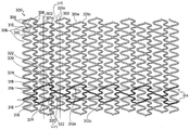
- FIG. 3 shows a pattern for a stent made in accordance with the present invention.
- FIG. 4 shows an enlarged view of one cell of the pattern of FIG. 3 .
- FIG. 5 shows a pattern for a stent made in accordance with the present invention
- FIG. 6 shows an enlarged view of one cell of the pattern of FIG. 5 .
- FIG. 7 shows a pattern for a stent made in accordance with the present invention.
- FIG. 8 shows an enlarged view of one cell used in the pattern of FIG. 7 .
- FIG. 9 shows an enlarged view of another cell used in FIG. 7 .
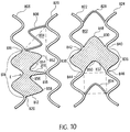
- FIG. 10 shows a schematic comparison of a four cornered or “square cell” and a three cornered or “triangular” cell of the present invention.
- FIG. 11 shows a pattern for a stent constructed according to the principles of the invention which has variable geometry along its length.
- FIG. 12 shows another pattern for a stent constructed according to the principles of the invention.
- FIG. 13 shows another pattern for a stent constructed according to the principles of the invention.
- FIG. 14 shows the expansion of a portion of a horizontal meander pattern built according to the principles of the invention.
- FIG. 15 shows a view of the shape of single cell on the outside of a curve superimposed on the same cell on the inside of a curve.
- FIG. 2 shows a schematic diagram of a longitudinally flexible stent 208 of the present invention.
- the stent 208 may be delivered to a curved vessel 210 by a balloon catheter, and implanted in the artery by inflating the balloon.
- the balloon causes the artery to straighten upon inflation of the balloon.
- the stent 208 assumes the natural curve of the vessel 210 because it is and remains longitudinally flexible after expansion. This reduces any potential stress points at the ends of the stent and along the length of the stent.
- the stent is longitudinally flexible after expansion, the stent will flex longitudinally with the vessel during the cycles caused by a heartbeat. This also reduces any cyclic stress at the ends of the stent and along the length of the stent.
- FIG. 3 shows a pattern of a stent according to the present invention.
- This pattern may be constructed of known materials, and for example stainless steel, but it is particularly suitable to be constructed from NiTi.
- the pattern can be formed by etching a flat sheet of NiTi into the pattern shown.
- the flat sheet is formed into a stent by rolling the etched sheet into a tubular shape, and welding the edges of the sheet together to form a tubular stent.
- the details of this method of forming the stent which has certain advantages, are disclosed in U.S. Pat. Nos. 5,836,964 and 5,997,973, which are hereby expressly incorporated by reference.
- NiTi stent is heat treated, as known by those skilled in the art, to take advantage of the shape memory characteristics of NiTi and its superelasticity.
- the pattern 300 is formed from a plurality of each of two orthogonal meander patterns which patterns are intertwined with each other.
- the term “meander pattern” is taken herein to describe a periodic pattern about a center line and “orthogonal meander patterns” are patterns whose center lines are orthogonal to each other.
- a meander pattern 301 is a vertical sinusoid having a vertical center line 302 . It will be recognized that this is not a perfect sinusoid, but only an approximation thereof. Thus, as used herein, the term sinusoid refers to a periodic pattern which varies positively and negatively symmetrically about an axis; it need not be an exact sine function.
- a meander pattern 301 has two loops 304 and 306 per period wherein loops 304 open to the right while loops 306 open to the left. Loops 304 and 306 share common members 308 and 310 , where member 308 joins one loop 304 to its following loop 306 and member 308 joins one loop 306 to its following loop 304 .
- the vertical sinusoid of meander pattern 301 has a first frequency.
- a meander pattern 312 (two of which have been shaded for reference) is a horizontal pattern having a horizontal center line 314 .
- a horizontal meander pattern 312 also has loops labeled 316 , 318 , 320 , 322 , and between the loops of a period is a section labeled 324 .
- these loops are part of a vertical sinusoid 303 which has a higher frequency than that of the meander patterns 301 .
- Vertical sinusoids 301 alternate with vertical sinusoids 303 .
- Vertical sinusoids 303 have a second frequency higher than the first frequency of the vertical meander patterns, i.e., sinusoids 301 .
- Vertical meander pattern 301 is provided in odd and even (o and e) versions which are 180° out of phase with each other.
- each left opening loop 306 of meander pattern 301 o faces a right opening loop 304 of meander pattern 301 e
- a right opening loop 304 of meander pattern 301 o faces a left opening loop 306 of meander pattern 301 e.
- the horizontal meander pattern 312 is also provided in odd and even forms.
- the straight sections 324 of the horizontal meander pattern 312 e intersect with every third common member 310 of the even vertical meander pattern 301 e .
- the straight sections 324 of the horizontal meander pattern 312 o also intersect with every third common member 310 of the odd vertical meander pattern 301 .
- alternating sinusoids 303 are intermittently coupled to the meander patterns 301 . For example, between points 315 and 317 , where vertical pattern 303 is coupled to vertical pattern 301 e , there are two loops 306 and one loop 304 of vertical pattern 301 e and three loops 319 and two loops 321 of vertical pattern 303 .
- this embodiment of the stent is made of NiTi, and it is reboundable, it typically will be self-expanding.
- the loops of the vertical meander patterns 301 open up in the vertical direction. This causes them to shorten in the horizontal direction.
- the loops in the horizontal meander pattern 312 open up both in the vertical direction and the horizontal direction, compensating for the shortening of the loops of the vertical meander patterns.
- the loops of the horizontal meander pattern 312 which are the loops of the vertical pattern 303 in the present invention avoids foreshortening in a self-expanding stent in a particularly effective manner.
- a self-expanding stent formed of a shape-memory alloy must be compressed from an expanded position to a compressed position for delivery.
- the length 606 of the horizontal meander pattern (width of the vertical pattern 330 ) naturally shrinks.
- a stent formed from the pattern of FIG. 3 and made of NiTi is particularly well suited for use in the carotid artery or other lumens subject to an outside pressure.
- One reason is that because the stent is formed of NiTi, it is reboundable, which is a desirable property for stents placed in the carotid artery.
- the other reason is that the stent of FIG. 3 offers excellent scaffolding, which is particularly important in the carotid artery. Scaffolding is especially important in the carotid artery because dislodged particles in the artery may embolize and cause a stroke.
- FIG. 4 is an expanded view of one flexible cell 500 of the pattern of FIG. 3 .
- Each flexible cell 500 includes: a first member 501 having a first end 502 and a second end 503 ; a second member 504 having a first end 505 and a second end 506 ; a third member 507 having a first end 508 and a second end 509 ; and a fourth member 510 having a first end 511 and a second end 512 .
- the first end 502 of the first member 501 is joined to the first end 505 of the second member 504 by a first curved member 535 to form a first loop 550
- the second end 506 of the second member 504 is joined to the second end 509 of the third member 508 by a second curved member 536
- the first end 508 of the third member 507 is joined to the first end 511 of the fourth member 510 by a third curved member 537 to form a second loop 531
- the first loop 530 defines a first angle 543
- the second loop 531 defines a second angle 544 .
- Each cell 500 also includes a fifth member 513 having a first end 514 and a second end 515 ; a sixth member 516 having a first end 517 and a second end 518 ; a seventh member 519 having a first end 520 and a second end 521 ; an eighth member 522 having a first end 523 and a second end 524 ; a ninth member 525 having a first end 526 and a second end 527 ; and a tenth member having a first end 529 and a second end 530 .
- the first end 514 of the fifth member 513 is joined to the second end 503 of the first member 501 at second junction point 542
- the second end 515 of the fifth member 513 is joined to the second end 518 of the sixth member by a curved member 539 to form a third loop 532
- the first end 517 of the sixth member 516 is joined to the first end 520 of the seventh member 519 by a fifth curved member 548
- the second end 521 of the seventh member 519 is joined to the second end 524 of the eighth member 522 at third junction point 540 to form a fourth loop 533
- the first end 523 of the eighth member 522 is joined to the first end 526 of the ninth member 525 by a sixth curved member 549
- the second end 526 of the ninth member 525 is joined to the second end 530 of the tenth member 528 by a seventh curved member 541 to form a fifth loop 534
- the first end 529 of the tenth member 528 is joined to the second end 512
- the first member 501 , the third member 507 , the sixth member 516 , the eighth member 522 , and the tenth member 528 have substantially the same angular orientation to the longitudinal axis of the stent and the second member 504 , the fourth member 510 , the fifth member 513 , the seventh member 519 , and the ninth member 512 have substantially the same angular orientation to the longitudinal axis of the stent.
- the lengths of the first, second, third and fourth members 501 , 504 , 507 , 510 are substantially equal.
- each cell includes two cycles of the lower frequency vertical pattern and three cycles of the higher frequency vertical pattern.
- the first, second, third, and fourth members 501 , 504 , 507 , 510 may have a width that is greater than the width of the fifth, sixth, seventh, eighth, ninth, and tenth members 513 , 516 , 519 , 522 , 525 , 528 in that cell.
- the differing widths of the first, second, third, and fourth members and the fifth, sixth, seventh, eighth, ninth, and tenth members with respect to each other contribute to the overall flexibility and resistance to radial compression of the cell.
- the widths of the various members can be tailored for specific applications. For example, the ratio of width may be approximately 50-70%.
- the fifth, sixth, seventh, eighth, ninth, and tenth members may be optimized predominantly to enable longitudinal flexibility, both before and after expansion, while the first, second, third, and fourth members may be optimized predominantly to enable sufficient resistance to radial compression to hold a vessel open.
- specific members may be optimized to predominantly enable a desired characteristic, all the portions of the cell interactively cooperate and contribute to the characteristics of the stent.
- FIGS. 5 and 6 show a pattern and an expanded view of one cell of an embodiment of the present invention which is specially adapted for a stent made of stainless steel.
- the pattern is similar to the pattern of FIGS. 3 and 4 , and the same reference numerals are used to indicate the generally corresponding parts.
- the stents of the embodiment of FIGS. 5 and 6 will normally be expanded by a balloon, in conventional fashion.
- FIGS. 3 and 5 can also be viewed as being made up of high frequency and low frequency vertical sinusoidal patterns or vertical loop containing sections which are arranged generally in the circumferential direction and which are periodically interconnected.
- first loop containing section with loops occurring at a first frequency extending along line 301 and a second loop containing section with also occurring at said first frequency extending along line 302 .
- a third loop containing section 303 extending along line 305 has loops occurring at a second frequency that is higher than said first frequency. It is disposed between the first and second loop containing sections and alternately joined to the first and second loop containing sections.
- the high frequency is in a ratio of 3/2 to the low frequency.
- the higher frequency loop containing elements are smaller in width.
- the relative widths can be selected so that the high frequency elements are crimpable to the same diameter as the lower frequency elements.
- a stent according to claim 4 wherein the higher frequency elements provide improved flexibility.
- the high frequency vertical patterns of smaller width result in elements having a lower maximal strain.
- the lower maximal strain is below the maximum strain without non-elastic deformation for the material of the stent.
- the lower maximal strain is below approximately 0.4%, even for a 150° bend, as confirmed by finite element analysis.
- a '303 type stent for an equivalent amount of bending, exhibits a maximum strain of 8%.
- the increased flexibility of the stent of the present invention means that, in addition to conforming better to the curved lumen, it will bend with each beat of the heart.
- the strain during heart beat happens 8,000,000 times every year and cannot be much above elastic limit without the stent breaking. Since, embodiments of the present invention keep the strain below the limit means that the stent of the present invention can bend with the lumen as the heart beats, for many years without breaking.
- the second loops 531 are made stronger by shortening the third and fourth members 507 , 510 . This helps assure that the second loops do not “flare out” during delivery of the stent through tortuous anatomy. This “flaring out” is not a concern with NiTi stents which are covered by a sheath during delivery.
- the length of the members in this embodiment may be shorter than the length of the corresponding members in the embodiment illustrated in FIGS. 3 and 4 .
- the amount of strain allowed in a self-expanding NiTi stent may be around 10%.
- the amount of strain allowed during the plastic deformation which take place, for example, during expansion typically may be 20% or greater. Therefore, to facilitate stents made of NiTi and stents made of stainless steel expanding to comparable diameters, the members of the NiTi stent may be longer than the members of a stainless steel stent.
- the stent When the stent is within a curved lumen when it is expanded, the stent is curved as shown in FIG. 2
- the result of this curving, for a single cell 500 is shown in FIG. 15 .
- the cells on the outside of the curve open in length, but narrow in width whereas the cells on the inside of the curve shorten in length but thicken in width.
- the density of the members per unit of surface area remains closer to what it is in an uncurved, expanded condition, both on the inside and outside of the curve.
- the area of the cell remains more constant than it would without compensation.
- the ratio between a toxic dose and an effective dose may be smaller than 10:1.
- the cell will open up increasing the length of the cell.
- the adjoining struts will come closer to each other, to cause the cell to become narrower in width, or in the circumferential direction, compensating for the increase in length.
- the longitudinal distances must decrease. Again, it is easy to see that the compression which occurs on the inside results in the struts on either side of the junction points 542 and 538 being squeezed closed and the width of the cell decreasing.
- the struts will move further apart from each other and the cell becomes more narrow in length but thicker in width again providing compensation.
- the increase in one direction is compensated in the other direction to make the area more constant than it would have been without the compensation.
- FIG. 7 illustrates another aspect of the present invention.
- the stent of FIG. 7 is also constructed from orthogonal meander patterns 301 , 302 .
- the meander patterns form a series of interlocking cells 50 , 700 of two types.
- the first type of cell 50 is taught by U.S. Pat. No. 5,733,303. These cells are arranged so that they form alternating bands 704 of first type of cells 50 and bands 706 of the second type of cells 700 .
- each of the '303 cells 50 has a first longitudinal apex 100 and a second longitudinal end 78 .
- Each cell 50 also is provided with a first longitudinal end 77 and a second longitudinal apex 104 disposed at the second longitudinal end 78 .
- Each cell 50 also includes a first member 51 having a longitudinal component having a first end 52 and a second end 53 ; a second member 54 having a longitudinal component having a first end 55 and a second end 56 ; a third member 57 having a longitudinal component having a first end 58 and a second end 59 ; and a fourth member 60 having a longitudinal component having a first end 61 and a second end 62 .
- the stent also includes a first loop or curved member 63 defining a first angle 64 disposed between the first end 52 of the first member 51 and the first end 55 of the second member 54 .
- a second loop or curved member 65 defining a second angle 66 is disposed between the second end 59 of the third member 57 and the second end 62 of the fourth member 60 and is disposed generally opposite to the first loop 63 .
- a first flexible compensating member (or a section of a longitudinal meander pattern) 67 having curved portion and two legs with a first end 68 and a second end 69 is disposed between the first member 51 and the third member 57 with the first end 68 of the first flexible compensating member 67 joined to and communicating with the second end 53 of the first member 51 and the second end 69 of the first flexible compensating member 67 joined to and communicating with the first end 58 of the third member 57 .
- the first end 68 and the second end 69 are disposed a variable longitudinal distance 70 from each other.
- a second flexible compensating member (or, a section of a longitudinal meander pattern) 71 having a first end 72 and a second end 73 is disposed between the second member 54 and the fourth member 60 .
- the first end 72 of the second flexible compensating member 71 is joined to and communicates with the second end 56 of the second member 54 and the second end 73 of the second flexible compensating member 71 is joined to and communicates with the first end 61 of the fourth member 60 .
- the first end 72 and the second end 73 are disposed a variable longitudinal distance 74 from each other.
- the first and second flexible compensating members, and particularly the curved portion thereof, 67 and 71 are arcuate.
- the flexible connecting members 67 and 71 will open up increasing the distances 70 and 74 .
- the members 57 and 60 will come closer to each other, as will members 51 and 54 . This will further lengthen the cell. But at the same time it will become narrower in width, or in the circumferential direction to compensate for the opening up of the flexible connector members 67 and 71 .
- the longitudinal distances must decrease. Again, if is easy to see that the compression which occurs on the inside results in the loops 67 and 71 being squeezed closed and the distances 70 and 74 decreasing.
- the members 57 and 60 and members 51 and 54 will move further apart from each other and the longitudinal components of members 57 , 60 , 51 and 54 will decrease.
- the cell becomes narrower in length but thicker in width.
- the increase in one direction is compensated in the other direction to make the area more constant than it would have been without the compensation.
- each flexible compensating member 67 , 71 includes: a first portion or leg 79 with a first end 80 and a second end 81 ; a second portion or leg 82 with a first end 83 and a second end 84 ; and a third portion or leg 85 with the first end 86 and a second end 87 , with the second end 81 and the second end 84 being joined by a curved member and the first end 83 and the first end 86 being joined by a curved member.
- the first end of a flexible compensating member 67 , 71 is the same as the first end 80 of the first portion 79
- the second end of a flexible compensating member 67 , 71 is the same as the second end 87 of the third portion 85 .
- a first area of inflection 88 is disposed between the second end 81 of the first portion 79 and the second end 84 of the second portion 82 where the curved portion joining them lies.
- a second area of inflection 89 is disposed between the first end 83 of the second portion 82 and the first end 86 of the third portion 85 where the curved portion joining them lies.
- FIG. 7 illustrates a pattern of alternating bands of cells
- the stent may be optimized for a particular usage by tailoring the configuration of the bands.
- the middle band of the second type of cells 700 may instead be formed of cells 50 , or vice versa.
- the second type of cells in FIG. 7 may also utilize the cell configurations described with respect to FIGS. 4 and 6 .
- the cell configurations of FIGS. 4 and 6 provide the advantage that they will not cause any torque of one portion of the cell relative to another portion of the cell about the longitudinal axis of the stent upon expansion, which may happen when the second type of cells 700 expand, a torque which could cause a stent to deform, and stick out.
- all of the flexible compensating members are arranged so that the path of the flexible compensating members, from left to right, travels in a generally downward direction.
- the cells 700 can also be arranged so that the flexible compensating members in one band are arranged in a generally upward direction, and the flexible compensating members in an adjacent band are arranged in a generally downward direction.
- One skilled in the art can easily make these modifications.
- FIG. 10 is a schematic representation comparing the cells 804 of the present invention, which have three points where the intertwined first and second meander patterns meet and are in that sense three cornered or triangular cells, with cells 802 of the '303 stent which have four points where the intertwined first and second meander patterns meet and are in that sense four cornered or square cells. More particularly, on the left side of FIG. 10 , a pair of vertical meander patterns 806 , 826 are joined by members 808 , 810 , 812 (which are sections of longitudinal meander patterns) to form a plurality of three cornered or triangular cells 804 .
- triangular cell it is meant that there are three sections 810 , 812 , 814 , each having loop portions and three associated points 816 , 818 , 820 of their joining, forming each cell.
- a pair of vertical meander patterns 822 , 824 are joined together compensating members 828 , 830 , 832 , 834 (which are sections of a longitudinal meander) to form a plurality of square cells 804 .
- square cell it is meant that there are four sections, each having loop portions, and four associated points of their joining, forming each cell.
- the shaded cell 802 is formed from four sections 832 , 836 , 830 , 838 , with four associated points of their joining 840 , 842 , 844 , 846 .
- Both the square cell and the triangular cell have two kinds of sections with loops.
- the first kind of loop containing section is formed from a vertical meander pattern and is optimized predominantly to enable radial support.
- the second kind of loop containing section is optimized predominantly to enable flexibility along the longitudinal axis of the stent.
- each loop containing section is optimized predominantly to enable a desired characteristic of the stent, the sections are interconnected and cooperate to define the characteristics of the stent. Therefore, the first kind of loop containing section contributes to the longitudinal flexibility of the stent, and the second kind of loop containing section contributes to the radial support of the stent.
- the second kind of loop containing sections 830 , 832 each have one inflection point 848 , 850 .
- the loop containing sections 810 , 812 each have two inflection point areas 852 , 854 , 856 , 858 .
- the higher number of inflection points allows more freedom to deform after expansion of the stent and distributes the deformation over a longer section, thus, reducing the maximal strain along these loop containing sections.
- a square cell 802 is generally more elongated along the longitudinal axis of the stent than a triangular cell 804 , which is generally more elongated along the circumference of the stent. This also contributes to higher flexibility after expansion.
- the area of a triangular cell 804 is the same as a square cell 802 .
- a triangular cell offers increased coverage of a vessel wall.
- the stent is substantially uniform over its entire length.
- a band of cells 850 may be designed to provide different flexibility characteristics or different radial compression characteristics than the remaining bands of cells by altering the widths and lengths of the members making up that band.
- the stent may be adapted to provide increased access to a side branch lumen by providing at least one cell 852 which is larger in size then the remaining cells, or by providing an entire band of cells 854 which are larger in size than the other bands of cells.
- the stent may be designed to expand to different diameters along the length of the stent.
- the stent may also be treated after formation of the stent by coating the stent with a medicine, plating the stent with a protective material, plating the stent with a radiopaque material, or covering the stent with a material.
- FIGS. 12 and 13 show alternative patterns for a stent constructed according to the principles of the present invention.
- the stent shown in FIG. 12 has two bands of cells 856 located at each of the proximal end 860 and distal and 862 .
- the cells that form the bands of cells 856 located at the ends of the stent are '303 type cells.
- the remaining cells in the stent are the same as described with respect to the cells 500 depicted in FIG. 6 .
- the stent shown in FIG. 13 has alternating bands of cells 864 , 866 , 868 .
- the first type of band of cells 864 is composed of '303 type cells.
- the second and third types of bands of cells 866 , 868 are formed of the cells described with respect to the cells 500 depicted in FIG. 4 .
- any various combination of cells may be used in the present invention.
Abstract
Description
Claims (6)
Priority Applications (17)
| Application Number | Priority Date | Filing Date | Title |
|---|---|---|---|
| US09/864,389 US7828835B2 (en) | 2000-03-01 | 2001-05-25 | Longitudinally flexible stent |
| EP01125340A EP1304090A3 (en) | 2001-05-25 | 2001-10-29 | Longitudinally flexible stent |
| DE10153340A DE10153340A1 (en) | 2001-05-25 | 2001-10-29 | Stent for holding open blood vessel formed of intertwined meander patterns with series of triangular cells, has circumferential loop section, further loop section, and third loop section |
| CA002439081A CA2439081A1 (en) | 2001-05-25 | 2002-05-21 | Longitudinally flexible stent |
| PCT/IB2002/001743 WO2002094127A2 (en) | 2001-05-25 | 2002-05-21 | Longitudinally flexible stent |
| EP02733008A EP1463459A4 (en) | 2001-05-25 | 2002-05-21 | Longitudinally flexible stent |
| JP2002590851A JP2005503843A (en) | 2001-05-25 | 2002-05-21 | Longitudinal flexible stent |
| ARP020101926A AR033925A1 (en) | 2001-05-25 | 2002-05-23 | FLEXIBLE STENT IN LONGITUDINAL SENSE. |
| US10/236,144 US7621947B2 (en) | 2000-03-01 | 2002-09-06 | Longitudinally flexible stent |
| US10/757,805 US7758627B2 (en) | 2000-03-01 | 2004-01-14 | Longitudinally flexible stent |
| US12/042,470 US8202312B2 (en) | 2000-03-01 | 2008-03-05 | Longitudinally flexible stent |
| US12/644,688 US20100100166A1 (en) | 2000-03-01 | 2009-12-22 | Longitudinally flexible stent |
| US12/776,548 US20100228339A1 (en) | 2000-03-01 | 2010-05-10 | Longitudinally flexible stent |
| US12/842,292 US8920487B1 (en) | 2000-03-01 | 2010-07-23 | Longitudinally flexible stent |
| US12/898,513 US8496699B2 (en) | 2000-03-01 | 2010-10-05 | Longitudinally flexible stent |
| US13/761,729 US9161849B1 (en) | 2000-03-01 | 2013-02-07 | Longitudinally flexible stent |
| US14/850,316 US9968471B1 (en) | 2000-03-01 | 2015-09-10 | Longitudinally flexible stent |
Applications Claiming Priority (4)
| Application Number | Priority Date | Filing Date | Title |
|---|---|---|---|
| US09/516,753 US7141062B1 (en) | 2000-03-01 | 2000-03-01 | Longitudinally flexible stent |
| US20272300P | 2000-05-08 | 2000-05-08 | |
| US09/795,794 US6709453B2 (en) | 2000-03-01 | 2001-02-28 | Longitudinally flexible stent |
| US09/864,389 US7828835B2 (en) | 2000-03-01 | 2001-05-25 | Longitudinally flexible stent |
Related Parent Applications (3)
| Application Number | Title | Priority Date | Filing Date |
|---|---|---|---|
| US09/516,753 Continuation-In-Part US7141062B1 (en) | 2000-03-01 | 2000-03-01 | Longitudinally flexible stent |
| US09/765,794 Continuation-In-Part US6740346B2 (en) | 2001-01-19 | 2001-01-19 | System for packaging, storing and transporting agricultural produce |
| US09/795,794 Continuation-In-Part US6709453B2 (en) | 2000-03-01 | 2001-02-28 | Longitudinally flexible stent |
Related Child Applications (5)
| Application Number | Title | Priority Date | Filing Date |
|---|---|---|---|
| US10/236,144 Continuation-In-Part US7621947B2 (en) | 2000-03-01 | 2002-09-06 | Longitudinally flexible stent |
| US10/757,805 Continuation-In-Part US7758627B2 (en) | 2000-03-01 | 2004-01-14 | Longitudinally flexible stent |
| US12/644,688 Continuation US20100100166A1 (en) | 2000-03-01 | 2009-12-22 | Longitudinally flexible stent |
| US12/898,513 Continuation-In-Part US8496699B2 (en) | 2000-03-01 | 2010-10-05 | Longitudinally flexible stent |
| US12/898,513 Continuation US8496699B2 (en) | 2000-03-01 | 2010-10-05 | Longitudinally flexible stent |
Publications (2)
| Publication Number | Publication Date |
|---|---|
| US20020022876A1 US20020022876A1 (en) | 2002-02-21 |
| US7828835B2 true US7828835B2 (en) | 2010-11-09 |
Family
ID=25343166
Family Applications (2)
| Application Number | Title | Priority Date | Filing Date |
|---|---|---|---|
| US09/864,389 Expired - Fee Related US7828835B2 (en) | 2000-03-01 | 2001-05-25 | Longitudinally flexible stent |
| US12/644,688 Abandoned US20100100166A1 (en) | 2000-03-01 | 2009-12-22 | Longitudinally flexible stent |
Family Applications After (1)
| Application Number | Title | Priority Date | Filing Date |
|---|---|---|---|
| US12/644,688 Abandoned US20100100166A1 (en) | 2000-03-01 | 2009-12-22 | Longitudinally flexible stent |
Country Status (7)
| Country | Link |
|---|---|
| US (2) | US7828835B2 (en) |
| EP (2) | EP1304090A3 (en) |
| JP (1) | JP2005503843A (en) |
| AR (1) | AR033925A1 (en) |
| CA (1) | CA2439081A1 (en) |
| DE (1) | DE10153340A1 (en) |
| WO (1) | WO2002094127A2 (en) |
Cited By (2)
| Publication number | Priority date | Publication date | Assignee | Title |
|---|---|---|---|---|
| US8449597B2 (en) | 1995-03-01 | 2013-05-28 | Boston Scientific Scimed, Inc. | Longitudinally flexible expandable stent |
| US20140285335A1 (en) * | 2013-03-15 | 2014-09-25 | Alfred M. Haas | Spc |
Families Citing this family (53)
| Publication number | Priority date | Publication date | Assignee | Title |
|---|---|---|---|---|
| US6896696B2 (en) * | 1998-11-20 | 2005-05-24 | Scimed Life Systems, Inc. | Flexible and expandable stent |
| US7959664B2 (en) * | 1996-12-26 | 2011-06-14 | Medinol, Ltd. | Flat process of drug coating for stents |
| US20040254635A1 (en) * | 1998-03-30 | 2004-12-16 | Shanley John F. | Expandable medical device for delivery of beneficial agent |
| US6241762B1 (en) | 1998-03-30 | 2001-06-05 | Conor Medsystems, Inc. | Expandable medical device with ductile hinges |
| US7208010B2 (en) | 2000-10-16 | 2007-04-24 | Conor Medsystems, Inc. | Expandable medical device for delivery of beneficial agent |
| US6755856B2 (en) | 1998-09-05 | 2004-06-29 | Abbott Laboratories Vascular Enterprises Limited | Methods and apparatus for stenting comprising enhanced embolic protection, coupled with improved protection against restenosis and thrombus formation |
| US6293967B1 (en) | 1998-10-29 | 2001-09-25 | Conor Medsystems, Inc. | Expandable medical device with ductile hinges |
| US6290673B1 (en) * | 1999-05-20 | 2001-09-18 | Conor Medsystems, Inc. | Expandable medical device delivery system and method |
| US8496699B2 (en) | 2000-03-01 | 2013-07-30 | Medinol Ltd. | Longitudinally flexible stent |
| US8920487B1 (en) | 2000-03-01 | 2014-12-30 | Medinol Ltd. | Longitudinally flexible stent |
| US7141062B1 (en) | 2000-03-01 | 2006-11-28 | Medinol, Ltd. | Longitudinally flexible stent |
| US7758627B2 (en) * | 2000-03-01 | 2010-07-20 | Medinol, Ltd. | Longitudinally flexible stent |
| US8202312B2 (en) | 2000-03-01 | 2012-06-19 | Medinol Ltd. | Longitudinally flexible stent |
| DE20122506U1 (en) | 2000-10-16 | 2005-12-08 | Conor Medsystems, Inc., Menlo Park | Expandable medical device for delivering a beneficial agent |
| US6764507B2 (en) | 2000-10-16 | 2004-07-20 | Conor Medsystems, Inc. | Expandable medical device with improved spatial distribution |
| US6964680B2 (en) * | 2001-02-05 | 2005-11-15 | Conor Medsystems, Inc. | Expandable medical device with tapered hinge |
| US20040073294A1 (en) | 2002-09-20 | 2004-04-15 | Conor Medsystems, Inc. | Method and apparatus for loading a beneficial agent into an expandable medical device |
| US7842083B2 (en) * | 2001-08-20 | 2010-11-30 | Innovational Holdings, Llc. | Expandable medical device with improved spatial distribution |
| EP1507494A2 (en) * | 2002-05-06 | 2005-02-23 | Abbott Laboratories | Endoprosthesis for controlled contraction and expansion |
| EP2529707B1 (en) * | 2002-05-08 | 2015-04-15 | Abbott Laboratories | Endoprosthesis having foot extensions |
| US20040054398A1 (en) * | 2002-09-13 | 2004-03-18 | Cully Edward H. | Stent device with multiple helix construction |
| US20040127976A1 (en) * | 2002-09-20 | 2004-07-01 | Conor Medsystems, Inc. | Method and apparatus for loading a beneficial agent into an expandable medical device |
| US7223283B2 (en) * | 2002-10-09 | 2007-05-29 | Boston Scientific Scimed, Inc. | Stent with improved flexibility |
| US7331986B2 (en) * | 2002-10-09 | 2008-02-19 | Boston Scientific Scimed, Inc. | Intraluminal medical device having improved visibility |
| EP1610823B1 (en) * | 2003-03-28 | 2011-09-28 | Innovational Holdings, LLC | Implantable medical device with continuous agent concentration gradient |
| US7625398B2 (en) * | 2003-05-06 | 2009-12-01 | Abbott Laboratories | Endoprosthesis having foot extensions |
| US7625401B2 (en) * | 2003-05-06 | 2009-12-01 | Abbott Laboratories | Endoprosthesis having foot extensions |
| US7169179B2 (en) * | 2003-06-05 | 2007-01-30 | Conor Medsystems, Inc. | Drug delivery device and method for bi-directional drug delivery |
| US7785653B2 (en) * | 2003-09-22 | 2010-08-31 | Innovational Holdings Llc | Method and apparatus for loading a beneficial agent into an expandable medical device |
| US20050182474A1 (en) * | 2004-02-13 | 2005-08-18 | Medtronic Vascular, Inc. | Coated stent having protruding crowns and elongated struts |
| JP4908743B2 (en) * | 2004-06-08 | 2012-04-04 | テルモ株式会社 | In vivo indwelling stent and biological organ dilator |
| DE102004045226B4 (en) | 2004-09-17 | 2008-01-17 | Optiray Medizintechnik Gmbh | support prosthesis |
| CA2610108C (en) | 2005-04-04 | 2014-03-25 | Burpee Materials Technology, Llc | Flexible stent |
| US20060248698A1 (en) * | 2005-05-05 | 2006-11-09 | Hanson Brian J | Tubular stent and methods of making the same |
| EP2364676B1 (en) | 2005-06-30 | 2018-12-19 | Abbott Laboratories | Endoprosthesis having foot extensions |
| US8828077B2 (en) * | 2006-03-15 | 2014-09-09 | Medinol Ltd. | Flat process of preparing drug eluting stents |
| US8414637B2 (en) * | 2006-09-08 | 2013-04-09 | Boston Scientific Scimed, Inc. | Stent |
| US7810223B2 (en) * | 2007-05-16 | 2010-10-12 | Boston Scientific Scimed, Inc. | Method of attaching radiopaque markers to intraluminal medical devices, and devices formed using the same |
| US8016874B2 (en) | 2007-05-23 | 2011-09-13 | Abbott Laboratories Vascular Enterprises Limited | Flexible stent with elevated scaffolding properties |
| US8128679B2 (en) | 2007-05-23 | 2012-03-06 | Abbott Laboratories Vascular Enterprises Limited | Flexible stent with torque-absorbing connectors |
| US7988723B2 (en) | 2007-08-02 | 2011-08-02 | Flexible Stenting Solutions, Inc. | Flexible stent |
| US8920488B2 (en) | 2007-12-20 | 2014-12-30 | Abbott Laboratories Vascular Enterprises Limited | Endoprosthesis having a stable architecture |
| US9149376B2 (en) | 2008-10-06 | 2015-10-06 | Cordis Corporation | Reconstrainable stent delivery system |
| CN102458314B (en) * | 2009-04-10 | 2014-09-17 | 泰科保健集团有限合伙公司 | Implants having high fatigue resistance, implant delivery systems, and methods of use |
| US9060889B2 (en) * | 2009-09-18 | 2015-06-23 | Medtronic Vascular, Inc. | Methods for forming an orthogonal end on a helical stent |
| EP2658484A1 (en) | 2010-12-30 | 2013-11-06 | Boston Scientific Scimed, Inc. | Multi stage opening stent designs |
| JP2014511247A (en) | 2011-03-03 | 2014-05-15 | ボストン サイエンティフィック サイムド,インコーポレイテッド | Low strain high strength stent |
| WO2012119037A1 (en) | 2011-03-03 | 2012-09-07 | Boston Scientific Scimed, Inc. | Stent with reduced profile |
| JP2011115634A (en) * | 2011-03-16 | 2011-06-16 | Terumo Corp | Indwelling stent and biological organ dilator |
| GB201106757D0 (en) * | 2011-04-20 | 2011-06-01 | Arterius Ltd | A stent |
| JP5695259B1 (en) * | 2014-02-19 | 2015-04-01 | 株式会社World Medish | High flexibility stent |
| WO2015200906A1 (en) | 2014-06-27 | 2015-12-30 | Boston Scientific Scimed, Inc. | Compositions, devices, kits and methods for attaching stent-containing medical devices to tissue |
| DE102015120142A1 (en) * | 2015-11-20 | 2017-05-24 | Biotronik Se & Co. Kg | Stent with flexible edge segment |
Citations (85)
| Publication number | Priority date | Publication date | Assignee | Title |
|---|---|---|---|---|
| US4733665A (en) | 1985-11-07 | 1988-03-29 | Expandable Grafts Partnership | Expandable intraluminal graft, and method and apparatus for implanting an expandable intraluminal graft |
| US4755593A (en) | 1985-07-24 | 1988-07-05 | Lauren Mark D | Novel biomaterial of cross-linked peritoneal tissue |
| US4886062A (en) | 1987-10-19 | 1989-12-12 | Medtronic, Inc. | Intravascular radially expandable stent and method of implant |
| US5037377A (en) | 1984-11-28 | 1991-08-06 | Medtronic, Inc. | Means for improving biocompatibility of implants, particularly of vascular grafts |
| US5133732A (en) | 1987-10-19 | 1992-07-28 | Medtronic, Inc. | Intravascular stent |
| DE4303181A1 (en) | 1993-02-04 | 1994-08-11 | Angiomed Ag | Implantable catheter |
| EP0623354A1 (en) | 1993-04-26 | 1994-11-09 | Medtronic, Inc. | Intravascular stents |
| US5510077A (en) | 1992-03-19 | 1996-04-23 | Dinh; Thomas Q. | Method of making an intraluminal stent |
| US5554182A (en) | 1992-03-19 | 1996-09-10 | Medtronic, Inc. | Method for preventing restenosis |
| US5575818A (en) | 1995-02-14 | 1996-11-19 | Corvita Corporation | Endovascular stent with locking ring |
| DE19512066A1 (en) | 1995-04-01 | 1996-11-28 | Variomed Ag | Stent for transluminal implantation e.g. blood vessels |
| US5591224A (en) | 1992-03-19 | 1997-01-07 | Medtronic, Inc. | Bioelastomeric stent |
| US5595571A (en) | 1994-04-18 | 1997-01-21 | Hancock Jaffe Laboratories | Biological material pre-fixation treatment |
| US5603721A (en) | 1991-10-28 | 1997-02-18 | Advanced Cardiovascular Systems, Inc. | Expandable stents and method for making same |
| DE29708879U1 (en) | 1997-05-20 | 1997-07-31 | Jomed Implantate Gmbh | Coronary stent |
| US5653747A (en) | 1992-12-21 | 1997-08-05 | Corvita Corporation | Luminal graft endoprostheses and manufacture thereof |
| US5693085A (en) | 1994-04-29 | 1997-12-02 | Scimed Life Systems, Inc. | Stent with collagen |
| US5695516A (en) | 1996-02-21 | 1997-12-09 | Iso Stent, Inc. | Longitudinally elongating balloon expandable stent |
| US5697971A (en) | 1996-06-11 | 1997-12-16 | Fischell; Robert E. | Multi-cell stent with cells having differing characteristics |
| EP0830853A1 (en) | 1996-09-19 | 1998-03-25 | Medinol Ltd. | Stent with variable features to optimize support and method of making such stent |
| US5733303A (en) | 1994-03-17 | 1998-03-31 | Medinol Ltd. | Flexible expandable stent |
| FR2758253A1 (en) | 1997-01-10 | 1998-07-17 | Nycomed Lab Sa | IMPLANTABLE DEVICE FOR THE TREATMENT OF A BODY DUCT |
| US5800507A (en) | 1992-03-19 | 1998-09-01 | Medtronic, Inc. | Intraluminal stent |
| US5800508A (en) | 1994-02-09 | 1998-09-01 | Boston Scientific Technology, Inc. | Bifurcated endoluminal prosthesis |
| NZ280547A (en) | 1994-11-28 | 1998-09-24 | Advanced Cardiovascular System | Expandable metal stent comprising a plurality of cut, interconnected cylindrical elements |
| US5827321A (en) | 1997-02-07 | 1998-10-27 | Cornerstone Devices, Inc. | Non-Foreshortening intraluminal prosthesis |
| EP0876216A1 (en) | 1995-08-22 | 1998-11-11 | Emitec Gesellschaft für Emissionstechnologie mbH | Layered sheet metal with rolled-on solder and process for manufacturing a honeycombed body therefrom |
| US5837313A (en) | 1995-04-19 | 1998-11-17 | Schneider (Usa) Inc | Drug release stent coating process |
| US5836964A (en) | 1996-10-30 | 1998-11-17 | Medinol Ltd. | Stent fabrication method |
| US5855600A (en) | 1997-08-01 | 1999-01-05 | Inflow Dynamics Inc. | Flexible implantable stent with composite design |
| US5855597A (en) | 1997-05-07 | 1999-01-05 | Iowa-India Investments Co. Limited | Stent valve and stent graft for percutaneous surgery |
| US5865723A (en) | 1995-12-29 | 1999-02-02 | Ramus Medical Technologies | Method and apparatus for forming vascular prostheses |
| NZ285241A (en) | 1995-04-26 | 1999-03-29 | Medinol Ltd | Articulated stent with area of inflection between neighbouring portions |
| US5895407A (en) | 1996-08-06 | 1999-04-20 | Jayaraman; Swaminathan | Microporous covered stents and method of coating |
| US5913895A (en) | 1997-06-02 | 1999-06-22 | Isostent, Inc. | Intravascular stent with enhanced rigidity strut members |
| US5922021A (en) | 1996-04-26 | 1999-07-13 | Jang; G. David | Intravascular stent |
| DE19753123A1 (en) | 1997-11-29 | 1999-08-05 | Braun Melsungen Ag | Vascular support tube has new design of structure for more elasticity |
| EP0958794A2 (en) | 1998-05-16 | 1999-11-24 | Jomed Implantate GmbH | Radially expandable stent for implantation into a corporeal vessel |
| US5997973A (en) | 1997-11-18 | 1999-12-07 | Hughes Electronics Corporation | Articulating thermal membrane with integral hinges |
| US6013091A (en) | 1997-10-09 | 2000-01-11 | Scimed Life Systems, Inc. | Stent configurations |
| EP0970664A2 (en) | 1998-07-03 | 2000-01-12 | W.C. Heraeus GmbH & Co. KG | Radially expandable stent |
| NZ331532A (en) | 1997-11-13 | 2000-01-28 | Medinol Ltd | Stents for deploying in body lumens comprising a tubular body having a radiopaque coating |
| US6053941A (en) | 1994-05-26 | 2000-04-25 | Angiomed Gmbh & Co. Medizintechnik Kg | Stent with an end of greater diameter than its main body |
| DE19900411A1 (en) | 1999-01-08 | 2000-07-13 | Lothar Sellin | Stent with tubular flexible body has wall consisting of curved ribs joined by connecting pieces |
| EP1020166A1 (en) | 1999-01-12 | 2000-07-19 | Orbus Medical Technologies, Inc. | Expandable intraluminal endoprosthesis |
| US6120847A (en) * | 1999-01-08 | 2000-09-19 | Scimed Life Systems, Inc. | Surface treatment method for stent coating |
| US6132461A (en) | 1998-03-27 | 2000-10-17 | Intratherapeutics, Inc. | Stent with dual support structure |
| US6159237A (en) | 1996-02-14 | 2000-12-12 | Inflow Dynamics, Inc. | Implantable vascular and endoluminal stents |
| US6162245A (en) * | 1997-05-07 | 2000-12-19 | Iowa-India Investments Company Limited | Stent valve and stent graft |
| US6179868B1 (en) * | 1998-03-27 | 2001-01-30 | Janet Burpee | Stent with reduced shortening |
| US6183353B1 (en) | 1997-06-06 | 2001-02-06 | Cook Incorporated | Apparatus for polishing surgical stents |
| US6190406B1 (en) | 1998-01-09 | 2001-02-20 | Nitinal Development Corporation | Intravascular stent having tapered struts |
| US6190403B1 (en) * | 1998-11-13 | 2001-02-20 | Cordis Corporation | Low profile radiopaque stent with increased longitudinal flexibility and radial rigidity |
| US6193747B1 (en) * | 1997-02-17 | 2001-02-27 | Jomed Implantate Gmbh | Stent |
| US6197048B1 (en) | 1996-12-26 | 2001-03-06 | Medinol Ltd. | Stent |
| US6221098B1 (en) | 1997-08-13 | 2001-04-24 | Advanced Cardiovascular Systems, Inc. | Stent and catheter assembly and method for treating bifurcations |
| US6231598B1 (en) * | 1997-09-24 | 2001-05-15 | Med Institute, Inc. | Radially expandable stent |
| US6241762B1 (en) | 1998-03-30 | 2001-06-05 | Conor Medsystems, Inc. | Expandable medical device with ductile hinges |
| US6251134B1 (en) | 1999-02-28 | 2001-06-26 | Inflow Dynamics Inc. | Stent with high longitudinal flexibility |
| DE19957063A1 (en) | 1999-11-26 | 2001-08-02 | Franz Herbst | Stent and method for its manufacture |
| EP1129673A2 (en) | 2000-03-01 | 2001-09-05 | Medinol Ltd. | Longitudinally flexible stent |
| US6299604B1 (en) * | 1998-08-20 | 2001-10-09 | Cook Incorporated | Coated implantable medical device |
| DE20108765U1 (en) | 2001-05-25 | 2001-10-31 | Medinol Ltd | Longitudinally flexible stent |
| DE20108764U1 (en) | 2001-05-25 | 2001-11-29 | Medinol Ltd | Stent |
| US20010056298A1 (en) | 1995-03-01 | 2001-12-27 | Brown Brian J. | Longitudinally flexible expandable stent |
| US20020007212A1 (en) | 1995-03-01 | 2002-01-17 | Brown Brian J. | Longitudinally flexible expandable stent |
| US6383213B2 (en) | 1999-10-05 | 2002-05-07 | Advanced Cardiovascular Systems, Inc. | Stent and catheter assembly and method for treating bifurcations |
| US20020055770A1 (en) | 1998-11-20 | 2002-05-09 | Doran Burns P. | Flexible and expandable stent |
| US6387120B2 (en) | 1999-12-09 | 2002-05-14 | Advanced Cardiovascular Systems, Inc. | Stent and catheter assembly and method for treating bifurcations |
| US6409753B1 (en) | 1999-10-26 | 2002-06-25 | Scimed Life Systems, Inc. | Flexible stent |
| US6416539B1 (en) | 1997-06-30 | 2002-07-09 | Medex, Inc. | Controlled length intraluminal implant |
| US20020103529A1 (en) | 2000-03-01 | 2002-08-01 | Gregory Pinchasik | Longitudinally flexible stent |
| US6428569B1 (en) | 1999-11-09 | 2002-08-06 | Scimed Life Systems Inc. | Micro structure stent configurations |
| US20020116049A1 (en) | 2000-09-22 | 2002-08-22 | Scimed Life Systems, Inc. | Stent |
| US20020138136A1 (en) | 2001-03-23 | 2002-09-26 | Scimed Life Systems, Inc. | Medical device having radio-opacification and barrier layers |
| US6471980B2 (en) | 2000-12-22 | 2002-10-29 | Avantec Vascular Corporation | Intravascular delivery of mycophenolic acid |
| US6478815B1 (en) | 2000-09-18 | 2002-11-12 | Inflow Dynamics Inc. | Vascular and endoluminal stents |
| US6540775B1 (en) | 2000-06-30 | 2003-04-01 | Cordis Corporation | Ultraflexible open cell stent |
| US6569180B1 (en) | 2000-06-02 | 2003-05-27 | Avantec Vascular Corporation | Catheter having exchangeable balloon |
| US6602281B1 (en) | 1995-06-05 | 2003-08-05 | Avantec Vascular Corporation | Radially expansible vessel scaffold having beams and expansion joints |
| US6602282B1 (en) | 2000-05-04 | 2003-08-05 | Avantec Vascular Corporation | Flexible stent structure |
| US6648911B1 (en) | 2000-11-20 | 2003-11-18 | Avantec Vascular Corporation | Method and device for the treatment of vulnerable tissue site |
| US6790227B2 (en) | 2001-03-01 | 2004-09-14 | Cordis Corporation | Flexible stent |
| US6955686B2 (en) | 2001-03-01 | 2005-10-18 | Cordis Corporation | Flexible stent |
| US20050273157A1 (en) | 2004-06-08 | 2005-12-08 | Gregory Pinchasik | Stent having struts with reverse direction curvature |
Family Cites Families (4)
| Publication number | Priority date | Publication date | Assignee | Title |
|---|---|---|---|---|
| US5183180A (en) * | 1990-12-03 | 1993-02-02 | Otto Industries, Inc. | Plastic refuse container |
| US5231598A (en) * | 1991-09-30 | 1993-07-27 | National Semiconductor Corporation | Direct digital synthesis measurement signal skew tester |
| US5843101A (en) * | 1997-05-02 | 1998-12-01 | Fry; William R. | Disposable clip for temporary vessel occulsion |
| ATE376401T1 (en) * | 1998-11-20 | 2007-11-15 | Boston Scient Ltd | LONGITUDONLY FLEXIBLE AND EXPANDABLE STENT |
-
2001
- 2001-05-25 US US09/864,389 patent/US7828835B2/en not_active Expired - Fee Related
- 2001-10-29 EP EP01125340A patent/EP1304090A3/en not_active Withdrawn
- 2001-10-29 DE DE10153340A patent/DE10153340A1/en not_active Ceased
-
2002
- 2002-05-21 WO PCT/IB2002/001743 patent/WO2002094127A2/en not_active Application Discontinuation
- 2002-05-21 EP EP02733008A patent/EP1463459A4/en not_active Withdrawn
- 2002-05-21 CA CA002439081A patent/CA2439081A1/en not_active Abandoned
- 2002-05-21 JP JP2002590851A patent/JP2005503843A/en active Pending
- 2002-05-23 AR ARP020101926A patent/AR033925A1/en not_active Application Discontinuation
-
2009
- 2009-12-22 US US12/644,688 patent/US20100100166A1/en not_active Abandoned
Patent Citations (104)
| Publication number | Priority date | Publication date | Assignee | Title |
|---|---|---|---|---|
| US5037377A (en) | 1984-11-28 | 1991-08-06 | Medtronic, Inc. | Means for improving biocompatibility of implants, particularly of vascular grafts |
| US4755593A (en) | 1985-07-24 | 1988-07-05 | Lauren Mark D | Novel biomaterial of cross-linked peritoneal tissue |
| US4733665B1 (en) | 1985-11-07 | 1994-01-11 | Expandable Grafts Partnership | Expandable intraluminal graft,and method and apparatus for implanting an expandable intraluminal graft |
| US4733665C2 (en) | 1985-11-07 | 2002-01-29 | Expandable Grafts Partnership | Expandable intraluminal graft and method and apparatus for implanting an expandable intraluminal graft |
| US4733665A (en) | 1985-11-07 | 1988-03-29 | Expandable Grafts Partnership | Expandable intraluminal graft, and method and apparatus for implanting an expandable intraluminal graft |
| US5133732A (en) | 1987-10-19 | 1992-07-28 | Medtronic, Inc. | Intravascular stent |
| US4886062A (en) | 1987-10-19 | 1989-12-12 | Medtronic, Inc. | Intravascular radially expandable stent and method of implant |
| US5603721A (en) | 1991-10-28 | 1997-02-18 | Advanced Cardiovascular Systems, Inc. | Expandable stents and method for making same |
| US5554182A (en) | 1992-03-19 | 1996-09-10 | Medtronic, Inc. | Method for preventing restenosis |
| US5571166A (en) | 1992-03-19 | 1996-11-05 | Medtronic, Inc. | Method of making an intraluminal stent |
| US5849034A (en) | 1992-03-19 | 1998-12-15 | Medtronic, Inc. | Intraluminal stent |
| US5591224A (en) | 1992-03-19 | 1997-01-07 | Medtronic, Inc. | Bioelastomeric stent |
| US5510077A (en) | 1992-03-19 | 1996-04-23 | Dinh; Thomas Q. | Method of making an intraluminal stent |
| US5628785A (en) | 1992-03-19 | 1997-05-13 | Medtronic, Inc. | Bioelastomeric stent |
| US5800507A (en) | 1992-03-19 | 1998-09-01 | Medtronic, Inc. | Intraluminal stent |
| US5653747A (en) | 1992-12-21 | 1997-08-05 | Corvita Corporation | Luminal graft endoprostheses and manufacture thereof |
| DE4303181A1 (en) | 1993-02-04 | 1994-08-11 | Angiomed Ag | Implantable catheter |
| US5860999A (en) | 1993-02-04 | 1999-01-19 | Angiomed Gmbh & Co.Medizintechnik Kg | Stent and method of using same |
| US5707386A (en) | 1993-02-04 | 1998-01-13 | Angiomed Gmbh & Company Medizintechnik Kg | Stent and method of making a stent |
| EP0623354A1 (en) | 1993-04-26 | 1994-11-09 | Medtronic, Inc. | Intravascular stents |
| US5800508A (en) | 1994-02-09 | 1998-09-01 | Boston Scientific Technology, Inc. | Bifurcated endoluminal prosthesis |
| US5733303A (en) | 1994-03-17 | 1998-03-31 | Medinol Ltd. | Flexible expandable stent |
| US5595571A (en) | 1994-04-18 | 1997-01-21 | Hancock Jaffe Laboratories | Biological material pre-fixation treatment |
| US5720777A (en) | 1994-04-18 | 1998-02-24 | Hancock Jaffee Laboratories | Biological material pre-fixation treatment |
| US5843180A (en) | 1994-04-18 | 1998-12-01 | Hancock Jaffe Laboratories | Method of treating a mammal having a defective heart valve |
| US5843181A (en) | 1994-04-18 | 1998-12-01 | Hancock Jaffe Laboratories | Biological material pre-fixation treatment |
| US5693085A (en) | 1994-04-29 | 1997-12-02 | Scimed Life Systems, Inc. | Stent with collagen |
| US6053941A (en) | 1994-05-26 | 2000-04-25 | Angiomed Gmbh & Co. Medizintechnik Kg | Stent with an end of greater diameter than its main body |
| NZ280547A (en) | 1994-11-28 | 1998-09-24 | Advanced Cardiovascular System | Expandable metal stent comprising a plurality of cut, interconnected cylindrical elements |
| US5575818A (en) | 1995-02-14 | 1996-11-19 | Corvita Corporation | Endovascular stent with locking ring |
| US6348065B1 (en) | 1995-03-01 | 2002-02-19 | Scimed Life Systems, Inc. | Longitudinally flexible expandable stent |
| US20020177893A1 (en) | 1995-03-01 | 2002-11-28 | Scimed Life Systems, Inc. | Longitudinally flexible expandable stent |
| US6776793B2 (en) * | 1995-03-01 | 2004-08-17 | Scimed Life Systems, Inc. | Longitudinally flexible expandable stent |
| US20010056298A1 (en) | 1995-03-01 | 2001-12-27 | Brown Brian J. | Longitudinally flexible expandable stent |
| US20020007212A1 (en) | 1995-03-01 | 2002-01-17 | Brown Brian J. | Longitudinally flexible expandable stent |
| DE19512066A1 (en) | 1995-04-01 | 1996-11-28 | Variomed Ag | Stent for transluminal implantation e.g. blood vessels |
| US5837313A (en) | 1995-04-19 | 1998-11-17 | Schneider (Usa) Inc | Drug release stent coating process |
| NZ285241A (en) | 1995-04-26 | 1999-03-29 | Medinol Ltd | Articulated stent with area of inflection between neighbouring portions |
| US6602281B1 (en) | 1995-06-05 | 2003-08-05 | Avantec Vascular Corporation | Radially expansible vessel scaffold having beams and expansion joints |
| US6605107B1 (en) | 1995-06-05 | 2003-08-12 | Avantec Vascular Corporation | Radially expansible vessel scaffolds mounted over balloons |
| EP0876216A1 (en) | 1995-08-22 | 1998-11-11 | Emitec Gesellschaft für Emissionstechnologie mbH | Layered sheet metal with rolled-on solder and process for manufacturing a honeycombed body therefrom |
| US5865723A (en) | 1995-12-29 | 1999-02-02 | Ramus Medical Technologies | Method and apparatus for forming vascular prostheses |
| US6159237A (en) | 1996-02-14 | 2000-12-12 | Inflow Dynamics, Inc. | Implantable vascular and endoluminal stents |
| US5695516A (en) | 1996-02-21 | 1997-12-09 | Iso Stent, Inc. | Longitudinally elongating balloon expandable stent |
| US5922021A (en) | 1996-04-26 | 1999-07-13 | Jang; G. David | Intravascular stent |
| US5697971A (en) | 1996-06-11 | 1997-12-16 | Fischell; Robert E. | Multi-cell stent with cells having differing characteristics |
| US5895407A (en) | 1996-08-06 | 1999-04-20 | Jayaraman; Swaminathan | Microporous covered stents and method of coating |
| US5807404A (en) | 1996-09-19 | 1998-09-15 | Medinol Ltd. | Stent with variable features to optimize support and method of making such stent |
| EP0830853A1 (en) | 1996-09-19 | 1998-03-25 | Medinol Ltd. | Stent with variable features to optimize support and method of making such stent |
| US5836964A (en) | 1996-10-30 | 1998-11-17 | Medinol Ltd. | Stent fabrication method |
| US6197048B1 (en) | 1996-12-26 | 2001-03-06 | Medinol Ltd. | Stent |
| FR2758253A1 (en) | 1997-01-10 | 1998-07-17 | Nycomed Lab Sa | IMPLANTABLE DEVICE FOR THE TREATMENT OF A BODY DUCT |
| US5827321A (en) | 1997-02-07 | 1998-10-27 | Cornerstone Devices, Inc. | Non-Foreshortening intraluminal prosthesis |
| US6193747B1 (en) * | 1997-02-17 | 2001-02-27 | Jomed Implantate Gmbh | Stent |
| US6162245A (en) * | 1997-05-07 | 2000-12-19 | Iowa-India Investments Company Limited | Stent valve and stent graft |
| US5855597A (en) | 1997-05-07 | 1999-01-05 | Iowa-India Investments Co. Limited | Stent valve and stent graft for percutaneous surgery |
| US6017365A (en) | 1997-05-20 | 2000-01-25 | Jomed Implantate Gmbh | Coronary stent |
| DE29708879U1 (en) | 1997-05-20 | 1997-07-31 | Jomed Implantate Gmbh | Coronary stent |
| US5913895A (en) | 1997-06-02 | 1999-06-22 | Isostent, Inc. | Intravascular stent with enhanced rigidity strut members |
| US6183353B1 (en) | 1997-06-06 | 2001-02-06 | Cook Incorporated | Apparatus for polishing surgical stents |
| US6416539B1 (en) | 1997-06-30 | 2002-07-09 | Medex, Inc. | Controlled length intraluminal implant |
| US5855600A (en) | 1997-08-01 | 1999-01-05 | Inflow Dynamics Inc. | Flexible implantable stent with composite design |
| US6221098B1 (en) | 1997-08-13 | 2001-04-24 | Advanced Cardiovascular Systems, Inc. | Stent and catheter assembly and method for treating bifurcations |
| US6231598B1 (en) * | 1997-09-24 | 2001-05-15 | Med Institute, Inc. | Radially expandable stent |
| US20040088043A1 (en) | 1997-10-03 | 2004-05-06 | Avantec Vascular Corporation | Radially expansible vessel scaffold having modified radiopacity |
| US6416538B1 (en) | 1997-10-09 | 2002-07-09 | Scimed Life Systems, Inc. | Stent configurations |
| US6013091A (en) | 1997-10-09 | 2000-01-11 | Scimed Life Systems, Inc. | Stent configurations |
| NZ331532A (en) | 1997-11-13 | 2000-01-28 | Medinol Ltd | Stents for deploying in body lumens comprising a tubular body having a radiopaque coating |
| US5997973A (en) | 1997-11-18 | 1999-12-07 | Hughes Electronics Corporation | Articulating thermal membrane with integral hinges |
| DE19753123A1 (en) | 1997-11-29 | 1999-08-05 | Braun Melsungen Ag | Vascular support tube has new design of structure for more elasticity |
| US6190406B1 (en) | 1998-01-09 | 2001-02-20 | Nitinal Development Corporation | Intravascular stent having tapered struts |
| US6179868B1 (en) * | 1998-03-27 | 2001-01-30 | Janet Burpee | Stent with reduced shortening |
| US6132461A (en) | 1998-03-27 | 2000-10-17 | Intratherapeutics, Inc. | Stent with dual support structure |
| US6241762B1 (en) | 1998-03-30 | 2001-06-05 | Conor Medsystems, Inc. | Expandable medical device with ductile hinges |
| EP0958794A2 (en) | 1998-05-16 | 1999-11-24 | Jomed Implantate GmbH | Radially expandable stent for implantation into a corporeal vessel |
| US6652573B2 (en) | 1998-05-16 | 2003-11-25 | Jomed Gmbh | Radial expansible stent for implanting in body vessels |
| EP0970664A2 (en) | 1998-07-03 | 2000-01-12 | W.C. Heraeus GmbH & Co. KG | Radially expandable stent |
| US6299604B1 (en) * | 1998-08-20 | 2001-10-09 | Cook Incorporated | Coated implantable medical device |
| US6190403B1 (en) * | 1998-11-13 | 2001-02-20 | Cordis Corporation | Low profile radiopaque stent with increased longitudinal flexibility and radial rigidity |
| US20020055770A1 (en) | 1998-11-20 | 2002-05-09 | Doran Burns P. | Flexible and expandable stent |
| US6120847A (en) * | 1999-01-08 | 2000-09-19 | Scimed Life Systems, Inc. | Surface treatment method for stent coating |
| DE19900411A1 (en) | 1999-01-08 | 2000-07-13 | Lothar Sellin | Stent with tubular flexible body has wall consisting of curved ribs joined by connecting pieces |
| EP1020166A1 (en) | 1999-01-12 | 2000-07-19 | Orbus Medical Technologies, Inc. | Expandable intraluminal endoprosthesis |
| US6251134B1 (en) | 1999-02-28 | 2001-06-26 | Inflow Dynamics Inc. | Stent with high longitudinal flexibility |
| US6383213B2 (en) | 1999-10-05 | 2002-05-07 | Advanced Cardiovascular Systems, Inc. | Stent and catheter assembly and method for treating bifurcations |
| US6409753B1 (en) | 1999-10-26 | 2002-06-25 | Scimed Life Systems, Inc. | Flexible stent |
| US6428569B1 (en) | 1999-11-09 | 2002-08-06 | Scimed Life Systems Inc. | Micro structure stent configurations |
| DE19957063A1 (en) | 1999-11-26 | 2001-08-02 | Franz Herbst | Stent and method for its manufacture |
| US6387120B2 (en) | 1999-12-09 | 2002-05-14 | Advanced Cardiovascular Systems, Inc. | Stent and catheter assembly and method for treating bifurcations |
| US20020103529A1 (en) | 2000-03-01 | 2002-08-01 | Gregory Pinchasik | Longitudinally flexible stent |
| EP1129673A2 (en) | 2000-03-01 | 2001-09-05 | Medinol Ltd. | Longitudinally flexible stent |
| US6602282B1 (en) | 2000-05-04 | 2003-08-05 | Avantec Vascular Corporation | Flexible stent structure |
| US6569180B1 (en) | 2000-06-02 | 2003-05-27 | Avantec Vascular Corporation | Catheter having exchangeable balloon |
| US6540775B1 (en) | 2000-06-30 | 2003-04-01 | Cordis Corporation | Ultraflexible open cell stent |
| US6478815B1 (en) | 2000-09-18 | 2002-11-12 | Inflow Dynamics Inc. | Vascular and endoluminal stents |
| US20020116049A1 (en) | 2000-09-22 | 2002-08-22 | Scimed Life Systems, Inc. | Stent |
| US6648911B1 (en) | 2000-11-20 | 2003-11-18 | Avantec Vascular Corporation | Method and device for the treatment of vulnerable tissue site |
| US6471980B2 (en) | 2000-12-22 | 2002-10-29 | Avantec Vascular Corporation | Intravascular delivery of mycophenolic acid |
| US6790227B2 (en) | 2001-03-01 | 2004-09-14 | Cordis Corporation | Flexible stent |
| US6955686B2 (en) | 2001-03-01 | 2005-10-18 | Cordis Corporation | Flexible stent |
| US20020138136A1 (en) | 2001-03-23 | 2002-09-26 | Scimed Life Systems, Inc. | Medical device having radio-opacification and barrier layers |
| DE20108764U1 (en) | 2001-05-25 | 2001-11-29 | Medinol Ltd | Stent |
| DE20108765U1 (en) | 2001-05-25 | 2001-10-31 | Medinol Ltd | Longitudinally flexible stent |
| US20050273157A1 (en) | 2004-06-08 | 2005-12-08 | Gregory Pinchasik | Stent having struts with reverse direction curvature |
Non-Patent Citations (36)
| Title |
|---|
| Cancellation Proceeding against DE Patent No. 20108764. |
| Cancellation Proceeding against DE Patent No. 20108765. |
| European Search Report from corresponding EP Publication No. 1 908 437 dated Feb. 4, 2010, 5 pages. |
| German Office Action. |
| New Zealand Examination Report. |
| Office Action of related U.S. Appl. No. 10/619,387, Non-Final Office Action Mailed Jul. 23, 2008. |
| Office Action of related U.S. Appl. No. 10/660,883, Final Rejection Office Action Mailed Aug. 7, 2008. |
| Office Action of related U.S. Appl. No. 10/757,805, Non-Final Office Action Mailed Aug. 14, 2008. |
| Office Actions and Reponses to Office Actions of related U.S. Appl. No. 11/395,751: Final Rejection dated Jul. 14, 2010. |
| Office Actions and Reponses to Office Actions of related U.S. Appl. No. 12/042,470: Response to Non-Final Rejection dated Aug. 10, 2010; and Non-Final Rejection dated May 10, 2010. |
| Office Actions and Responses to Office Actions of related U.S. Appl. No. 09/516,753, issued as U.S. Pat. No. 7,141,062: Notice of Allowance mailed Jul. 28, 2006, Amendment and Response to Final Office Action dated Jun. 8, 2006. Final Office Action dated Dec. 8, 2005. Amendment and Response to Non-Final Office Action dated Aug. 15, 2005. Non-Final Office Action dated Mar. 15, 2005. Response to Election Requirement dated Nov. 2, 2004. Election Requirement dated Aug. 11, 2004. Amendment and Response to Final Office Action dated May 13, 2004. Final Office Action dated Feb. 6, 2004. Amendment and Response to Non-Final Office Action dated Nov. 13, 2003. Non-Final Office Action dated Aug. 13, 2003. Amendment and Response to Final Office Action dated Jun. 2, 2003. Final Office Action dated Dec. 3, 2002. Amendment and Response to Non-Final Office Action dated Jul. 26, 2002. Non-Final Office Action dated Jan. 30, 2002. |
| Office Actions and Responses to Office Actions of related U.S. Appl. No. 10/040,789, now abandoned: Notice of Abandonment dated Jun. 6, 2005, Response to Non-Compliant Amendment dated Apr. 21, 2005. Notice of Non-Compliant Amendment dated Mar. 21, 2005. Amendment and Response to Non-Final Office Action dated Feb. 24, 2005. Non-Final Office Action dated Aug. 25, 2004. Preliminary Amendment dated Jan. 16, 2003. |
| Office Actions and Responses to Office Actions of related U.S. Appl. No. 10/236,144 issued as US Patent No. 7,621,947: Notice of Allowance dated Jul. 13, 2009; Terminal Disclaimer filed, dated May 8, 2009; Amendment and Response to Non-Final Office Action with Extension of Time dated Feb. 2, 2009; Non-Final Rejection dated Oct. 2, 2008. |
| Office Actions and Responses to Office Actions of related U.S. Appl. No. 10/236,144: Amendment and Response to Final Office Action dated Jan. 9, 2008, Non-Final Office Action dated Sep. 21, 2007. Amendment and Responsse to Final Office Action dated Jun. 26, 2007, Final Office Action dated Feb. 26, 2007. Amendment and Response Non-Final Office Action dated Aug. 7, 2006. Non-Final Office Action dated Feb. 8, 2006. Response to Election Requirement dated Nov. 17, 2005. Election Requirement dated Sep. 21, 2005. |
| Office Actions and Responses to Office Actions of related U.S. Appl. No. 10/236,144: Final Office Action dated May 23, 2008. |
| Office Actions and Responses to Office Actions of related U.S. Appl. No. 10/619,837: Amendment and Response to Non-Final Office Action and Terminal Disclaimer dated Feb. 4, 2008. Non-Final Office Action dated Oct. 4, 2007. Response to Election Requirement dated Feb. 5, 2007. Election Requirement dated Jan. 4, 2007. |
| Office Actions and Responses to Office Actions of related U.S. Appl. No. 10/619,837: Notice of Allowance dated Oct. 13, 2009; Request for Continued Examination (RCE); Amendment and Response to Final Rejection dated Jul. 29, 2009; Final Rejection dated Apr. 29, 2009; Amendment and Response to Non-Final Rejection with Extension of Time dated Dec. 16, 2008. |
| Office Actions and Responses to Office Actions of related U.S. Appl. No. 10/660,883: Amendment and Response to Non-Final Office Action dated Jan. 25, 2008. Non-Final Office Action dated Oct. 25, 2007. |
| Office Actions and Responses to Office Actions of related U.S. Appl. No. 10/660,883: Notice of Abandonment dated Apr. 28, 2009; Advisory Action dated Jan. 30, 2009; Amendment and Response to Final Rejection with Extension of Time dated Jan. 7, 2009. |
| Office Actions and Responses to Office Actions of related U.S. Appl. No. 10/660,883: Requirement for Restriction/Election dated Apr. 28, 2008, Amendment and Response to Election Requirement dated May 28, 2008. |
| Office Actions and Responses to Office Actions of related U.S. Appl. No. 10/757,805: Amendment after Notice of Allowance dated Mar. 16, 2010; Notice of Allowance dated Dec. 17, 2009; Amendment and Response to Final Rejection with Request for Continued Examination (RCE) dated Jun. 29, 2009; Final Rejection dated Apr. 16, 2009; Amendment and Response to Non-Final Rejection with Extension of Time dated Jan. 14, 2009. |
| Office Actions and Responses to Office Actions of related U.S. Appl. No. 10/757,805: Requirement for Restriction/Election dated Apr. 7, 2008, Amendment and Response to Election Requirement dated May 7, 2008. |
| Office Actions and Responses to Office Actions of related U.S. Appl. No. 11/395,751: Amendment and Response to Election Requirement dated Dec. 10, 2007. Requirement for Restriction/Election dated Nov. 8, 2007. Amendment and Response to Non-Final Office Action dated Jul. 11, 2007. Non-Final Office Action dated Apr. 11, 2007. |
| Office Actions and Responses to Office Actions of related U.S. Appl. No. 11/395,751: Amendment and Response to Supplemental Non-Final Rejection dated Feb. 22, 2010; Supplemental Non-Final Rejection dated Nov. 20, 2009; Non-Final Rejection dated Oct. 20, 2009; Pre-Appeal Conference Decision dated Aug. 5, 2009; Notice of Appeal with Extension of Time and Pre-Brief Conference Request dated May 14, 2009;Final Rejection dated Dec. 15, 2008. |
| Office Actions and Responses to Office Actions of related U.S. Appl. No. 11/395,751: Non-Final Office Action dated Apr. 23, 2008. |
| Office Actions and Responses to Office Actions of related U.S. Appl. No. 12/042,470: Supplemental Amendment and Response to Non-Final Rejection dated Apr. 26, 2010; Correspondence dated Mar. 1, 2010 confirming that the Aug. 19, 2009 Restriction Requirement was sent in error by the Examiner; Non-Final Rejection/ Requirement for Restriction/Election dated Aug. 19, 2009; Response to Election/Restriction Requirement dated Apr. 20, 2009; Requirement for Restriction/Election dated Mar. 20, 2009; Amendment and Response to Non-Final Rejection dated Dec. 17, 2008; Supplemental Amendment and Response to Non-Final Rejection dated Dec. 17, 2008; Non-Final Rejection dated Sep. 17, 2008. |
| Office Actions, Responses to Office Actions and Notice of Allowance of related U.S. Appl. No. 09/795,794, issued as U.S. Pat. No. 6,709,453: Non-Final Office Action dated Dec. 20, 2001. Response to Office Action dated Jun. 19, 2002. Supplemental Amendment dated Aug. 5, 2002. Final Office Action dated Jan. 30, 2003. Amendment and Response to Final Office Action dated May 1, 2003. Non-Final Office Action dated Jul. 15, 2003, Amendment and Response to Final Office Action dated Sep. 11, 2003. Supplemental Response dated Sep. 17, 2003. Supplemental Response dated Sep. 22, 2003. Notice of Allowance dated Sep. 24, 2003. |
| Office Actions, Responses to Office Actions and Notice of Allowance of related U.S. Appl. No. 09/864,160, issued as U.S. Pat. No. 6,723,119: Non-Final Office Action dated Jan. 29, 2002. Amendment and Response to Non-Final Office Action dated Jun. 26, 2002. Supplemental Response dated Aug. 5, 2002. Final Office Action dated Dec. 3, 2002. Notice of Appeal dated Jun. 3, 2002. Notice of Allowance dated Sep. 26, 2003. Response After Final dated Sep. 11, 2003, Supplemental Response After Final dated Sep. 17, 2003. |
| Partial European Search Report. |
| Patent Act 1977: Search Report under Section 17. |
| PCT Search Reports. |
| Response to Office Action of related U.S. Appl. No. 11/395,751, Amendment and Reponse to Non-Final Rejection and Extension of Time dated Aug. 20, 2008. |
| Response to Office Action of related U.S. Appl. No.: 10/236,144, Amendment and Reponse to Final Rejection and Request for Contiued Examination dated Aug. 22, 2008. |
| Singapore Examination Report. |
| Supplementary European Search Report |
| Two European Search Reports. |
Cited By (3)
| Publication number | Priority date | Publication date | Assignee | Title |
|---|---|---|---|---|
| US8449597B2 (en) | 1995-03-01 | 2013-05-28 | Boston Scientific Scimed, Inc. | Longitudinally flexible expandable stent |
| US8728147B2 (en) | 1995-03-01 | 2014-05-20 | Boston Scientific Limited | Longitudinally flexible expandable stent |
| US20140285335A1 (en) * | 2013-03-15 | 2014-09-25 | Alfred M. Haas | Spc |
Also Published As
| Publication number | Publication date |
|---|---|
| US20100100166A1 (en) | 2010-04-22 |
| CA2439081A1 (en) | 2002-11-28 |
| JP2005503843A (en) | 2005-02-10 |
| WO2002094127A2 (en) | 2002-11-28 |
| EP1463459A2 (en) | 2004-10-06 |
| EP1304090A2 (en) | 2003-04-23 |
| DE10153340A1 (en) | 2002-11-28 |
| EP1463459A4 (en) | 2005-04-27 |
| AR033925A1 (en) | 2004-01-07 |
| US20020022876A1 (en) | 2002-02-21 |
| WO2002094127A3 (en) | 2004-07-22 |
| EP1304090A3 (en) | 2004-01-14 |
Similar Documents
| Publication | Publication Date | Title |
|---|---|---|
| US7828835B2 (en) | Longitudinally flexible stent | |
| CA2439088C (en) | Longitudinally flexible stent | |
| US6709453B2 (en) | Longitudinally flexible stent | |
| US7141062B1 (en) | Longitudinally flexible stent | |
| AU2004315736C1 (en) | Longitudinally flexible stent | |
| AU2002304381A1 (en) | Longitudinally flexible stent | |
| US7621947B2 (en) | Longitudinally flexible stent | |
| US8202312B2 (en) | Longitudinally flexible stent | |
| WO2003022172A2 (en) | Longitudinally flexible stent | |
| US8496699B2 (en) | Longitudinally flexible stent | |
| AU2002304380A1 (en) | Longitudinally flexible stent | |
| AU2002330689A1 (en) | Longitudinally flexible stent |
Legal Events
| Date | Code | Title | Description |
|---|---|---|---|
| AS | Assignment |
Owner name: MEDINOL LTD., ISRAEL Free format text: ASSIGNMENT OF ASSIGNORS INTEREST;ASSIGNORS:RICHTER, JACOB;PINCHASIK, GREGORY;REEL/FRAME:012161/0742;SIGNING DATES FROM 20010730 TO 20010803 |
|
| STCF | Information on status: patent grant |
Free format text: PATENTED CASE |
|
| FPAY | Fee payment |
Year of fee payment: 4 |
|
| MAFP | Maintenance fee payment |
Free format text: PAYMENT OF MAINTENANCE FEE, 8TH YEAR, LARGE ENTITY (ORIGINAL EVENT CODE: M1552) Year of fee payment: 8 |
|
| FEPP | Fee payment procedure |
Free format text: MAINTENANCE FEE REMINDER MAILED (ORIGINAL EVENT CODE: REM.); ENTITY STATUS OF PATENT OWNER: LARGE ENTITY |
|
| LAPS | Lapse for failure to pay maintenance fees |
Free format text: PATENT EXPIRED FOR FAILURE TO PAY MAINTENANCE FEES (ORIGINAL EVENT CODE: EXP.); ENTITY STATUS OF PATENT OWNER: LARGE ENTITY |
|
| STCH | Information on status: patent discontinuation |
Free format text: PATENT EXPIRED DUE TO NONPAYMENT OF MAINTENANCE FEES UNDER 37 CFR 1.362 |
|
| FP | Lapsed due to failure to pay maintenance fee |
Effective date: 20221109 |