US7552853B2 - Low-profile vascular closure systems and methods of using same - Google Patents
Low-profile vascular closure systems and methods of using same Download PDFInfo
- Publication number
- US7552853B2 US7552853B2 US11/626,633 US62663307A US7552853B2 US 7552853 B2 US7552853 B2 US 7552853B2 US 62663307 A US62663307 A US 62663307A US 7552853 B2 US7552853 B2 US 7552853B2
- Authority
- US
- United States
- Prior art keywords
- staple
- stapler
- tips
- elongate
- opposing
- Prior art date
- Legal status (The legal status is an assumption and is not a legal conclusion. Google has not performed a legal analysis and makes no representation as to the accuracy of the status listed.)
- Expired - Fee Related, expires
Links
Images


Classifications
-
- A—HUMAN NECESSITIES
- A61—MEDICAL OR VETERINARY SCIENCE; HYGIENE
- A61B—DIAGNOSIS; SURGERY; IDENTIFICATION
- A61B17/00—Surgical instruments, devices or methods, e.g. tourniquets
- A61B17/0057—Implements for plugging an opening in the wall of a hollow or tubular organ, e.g. for sealing a vessel puncture or closing a cardiac septal defect
-
- A—HUMAN NECESSITIES
- A61—MEDICAL OR VETERINARY SCIENCE; HYGIENE
- A61B—DIAGNOSIS; SURGERY; IDENTIFICATION
- A61B17/00—Surgical instruments, devices or methods, e.g. tourniquets
- A61B17/064—Surgical staples, i.e. penetrating the tissue
- A61B17/0644—Surgical staples, i.e. penetrating the tissue penetrating the tissue, deformable to closed position
-
- A—HUMAN NECESSITIES
- A61—MEDICAL OR VETERINARY SCIENCE; HYGIENE
- A61B—DIAGNOSIS; SURGERY; IDENTIFICATION
- A61B17/00—Surgical instruments, devices or methods, e.g. tourniquets
- A61B17/068—Surgical staplers, e.g. containing multiple staples or clamps
- A61B17/0682—Surgical staplers, e.g. containing multiple staples or clamps for applying U-shaped staples or clamps, e.g. without a forming anvil
- A61B17/0684—Surgical staplers, e.g. containing multiple staples or clamps for applying U-shaped staples or clamps, e.g. without a forming anvil having a forming anvil staying above the tissue during stapling
-
- A—HUMAN NECESSITIES
- A61—MEDICAL OR VETERINARY SCIENCE; HYGIENE
- A61B—DIAGNOSIS; SURGERY; IDENTIFICATION
- A61B17/00—Surgical instruments, devices or methods, e.g. tourniquets
- A61B17/068—Surgical staplers, e.g. containing multiple staples or clamps
- A61B17/0682—Surgical staplers, e.g. containing multiple staples or clamps for applying U-shaped staples or clamps, e.g. without a forming anvil
- A61B17/0686—Surgical staplers, e.g. containing multiple staples or clamps for applying U-shaped staples or clamps, e.g. without a forming anvil having a forming anvil staying below the tissue during stapling
-
- A—HUMAN NECESSITIES
- A61—MEDICAL OR VETERINARY SCIENCE; HYGIENE
- A61B—DIAGNOSIS; SURGERY; IDENTIFICATION
- A61B17/00—Surgical instruments, devices or methods, e.g. tourniquets
- A61B17/08—Wound clamps or clips, i.e. not or only partly penetrating the tissue ; Devices for bringing together the edges of a wound
- A61B17/083—Clips, e.g. resilient
-
- A—HUMAN NECESSITIES
- A61—MEDICAL OR VETERINARY SCIENCE; HYGIENE
- A61B—DIAGNOSIS; SURGERY; IDENTIFICATION
- A61B17/00—Surgical instruments, devices or methods, e.g. tourniquets
- A61B17/10—Surgical instruments, devices or methods, e.g. tourniquets for applying or removing wound clamps, e.g. containing only one clamp or staple; Wound clamp magazines
-
- A—HUMAN NECESSITIES
- A61—MEDICAL OR VETERINARY SCIENCE; HYGIENE
- A61B—DIAGNOSIS; SURGERY; IDENTIFICATION
- A61B17/00—Surgical instruments, devices or methods, e.g. tourniquets
- A61B17/02—Surgical instruments, devices or methods, e.g. tourniquets for holding wounds open; Tractors
- A61B17/0218—Surgical instruments, devices or methods, e.g. tourniquets for holding wounds open; Tractors for minimally invasive surgery
-
- A—HUMAN NECESSITIES
- A61—MEDICAL OR VETERINARY SCIENCE; HYGIENE
- A61B—DIAGNOSIS; SURGERY; IDENTIFICATION
- A61B17/00—Surgical instruments, devices or methods, e.g. tourniquets
- A61B17/068—Surgical staplers, e.g. containing multiple staples or clamps
- A61B17/072—Surgical staplers, e.g. containing multiple staples or clamps for applying a row of staples in a single action, e.g. the staples being applied simultaneously
- A61B17/07292—Reinforcements for staple line, e.g. pledgets
-
- A—HUMAN NECESSITIES
- A61—MEDICAL OR VETERINARY SCIENCE; HYGIENE
- A61B—DIAGNOSIS; SURGERY; IDENTIFICATION
- A61B17/00—Surgical instruments, devices or methods, e.g. tourniquets
- A61B17/0057—Implements for plugging an opening in the wall of a hollow or tubular organ, e.g. for sealing a vessel puncture or closing a cardiac septal defect
- A61B2017/00637—Implements for plugging an opening in the wall of a hollow or tubular organ, e.g. for sealing a vessel puncture or closing a cardiac septal defect for sealing trocar wounds through abdominal wall
-
- A—HUMAN NECESSITIES
- A61—MEDICAL OR VETERINARY SCIENCE; HYGIENE
- A61B—DIAGNOSIS; SURGERY; IDENTIFICATION
- A61B17/00—Surgical instruments, devices or methods, e.g. tourniquets
- A61B17/0057—Implements for plugging an opening in the wall of a hollow or tubular organ, e.g. for sealing a vessel puncture or closing a cardiac septal defect
- A61B2017/00646—Type of implements
- A61B2017/00668—Type of implements the implement being a tack or a staple
-
- A—HUMAN NECESSITIES
- A61—MEDICAL OR VETERINARY SCIENCE; HYGIENE
- A61B—DIAGNOSIS; SURGERY; IDENTIFICATION
- A61B17/00—Surgical instruments, devices or methods, e.g. tourniquets
- A61B17/22—Implements for squeezing-off ulcers or the like on the inside of inner organs of the body; Implements for scraping-out cavities of body organs, e.g. bones; Calculus removers; Calculus smashing apparatus; Apparatus for removing obstructions in blood vessels, not otherwise provided for
- A61B2017/22038—Implements for squeezing-off ulcers or the like on the inside of inner organs of the body; Implements for scraping-out cavities of body organs, e.g. bones; Calculus removers; Calculus smashing apparatus; Apparatus for removing obstructions in blood vessels, not otherwise provided for with a guide wire
-
- A—HUMAN NECESSITIES
- A61—MEDICAL OR VETERINARY SCIENCE; HYGIENE
- A61B—DIAGNOSIS; SURGERY; IDENTIFICATION
- A61B90/00—Instruments, implements or accessories specially adapted for surgery or diagnosis and not covered by any of the groups A61B1/00 - A61B50/00, e.g. for luxation treatment or for protecting wound edges
- A61B90/03—Automatic limiting or abutting means, e.g. for safety
- A61B2090/037—Automatic limiting or abutting means, e.g. for safety with a frangible part, e.g. by reduced diameter
-
- A—HUMAN NECESSITIES
- A61—MEDICAL OR VETERINARY SCIENCE; HYGIENE
- A61B—DIAGNOSIS; SURGERY; IDENTIFICATION
- A61B90/00—Instruments, implements or accessories specially adapted for surgery or diagnosis and not covered by any of the groups A61B1/00 - A61B50/00, e.g. for luxation treatment or for protecting wound edges
- A61B90/08—Accessories or related features not otherwise provided for
- A61B2090/0801—Prevention of accidental cutting or pricking
- A61B2090/08021—Prevention of accidental cutting or pricking of the patient or his organs
Definitions
- the present disclosure relates to system and method for closing an opening in a vessel wall after a medical procedure, and in particular, to a system and method for closing a puncture arteriotomy after an intra-luminal procedure such as catheterization.
- Catheters/catheterization procedures for diagnosis or treatment of cardiovascular and/or peripheral vascular diseases are well known, and typically involve the Seldinger technique to make insertions through layers of tissue and through a wall of the femoral artery.
- the arteriotomy puncture formed by the catheter or introducer sheath must be closed.
- the puncture opening in the artery typically ranges from 5 French (0.0655 inch, 1.67 mm) such as for a diagnostic angiography procedure to as large as 30 French (0.393 inch, 10.00 mm) for an interventional procedure such as implanting an inferior vena cava (IVC) filter.
- IVC inferior vena cava
- a method for closing an arteriotomy in a wall of a vessel of a body after an intra-luminal procedure is disclosed.
- the terms “distal” and “proximal” are used in the specification with respect to a position or direction relative to the treating clinician. “Distal” or “distally” are a position distant from or in a direction away from the clinician. “Proximal” and “proximally” are a position near or in a direction toward the clinician.
- the method may be practiced without a sheath in place in the tissue track. A guidewire from the intra-luminal procedure remains in the vessel or is replaced with another guidewire. A procedural sheath, if used, is removed from the patient.
- a dilator and a guiding system are advanced together along the guidewire into the body tissue, through the arteriotomy and are into the vessel lumen.
- the guiding system includes at least two stabilization wire guides, each stabilization wire guide having a deployable retention foot disposed at a distal portion thereof.
- the guiding system is deployed within the vessel lumen such that the retention feet can be pulled back against an inner surface of the vessel wall.
- the guidewire and dilator are withdrawn from the lumen and the body tissue, leaving only the guiding system in place.
- a closure system is advanced along the guiding system to a position proximal to the arteriotomy.
- the closure system includes a center tube housing a stapler, the center tube having at least two side tubes for riding along the stabilization wire guides. The stapler is then activated to close the arteriotomy and the guiding system and closure system are withdrawn from the lumen and the body.
- An embodiment of the stapler includes an elongate hollow shaft having at its distal end a pair of opposing actuation tips that define a staple chamber there between.
- An anvil extends into the staple chamber from one of the actuation lips to retain and deform a staple.
- An elongate driver is slidably disposed in the hollow shaft.
- a staple includes a pair of opposing legs proximally coupled by a bend and having an expansion ramp extending from each leg toward the other leg.
- the staple may be opened and/or closed by plastic or elastic deformation.
- the staple expansion ramps ride and spread apart along the anvil, thereby opening the staple. As the operator continues to push the driver longitudinally, the staple expansion ramps clear the anvil, permitting the staple to close.
- the driver closes the staple by deforming the staple bend against the anvil.
- the staple is elastically self-closing. A staple release mechanism is actuated to spread the actuation tips apart, creating a gap through which the staple is released from the anvil.
- a distal portion of the center tube is pinched such that it separates the staple tips from the tissue track during delivery to the arteriotomy site. When the staple is deployed, the staple spreads the pinched portion apart.
- a frangible cap is disposed over the distal opening of the center tube.
- the frangible cap separates the staple tips from the tissue track during delivery to the arteriotomy site.
- the staple perforates or fractures the frangible cap.
- a portion of the frangible cap tears away from the center tube to form a pledget that is retained against the arteriotomy by the staple.
- FIG. 1 is a cross-sectional view of body tissue including a vessel with a procedural device inserted in the vessel.
- FIG. 2 is cross-sectional view of body tissue including a vessel with a guidewire inserted in the vessel.
- FIG. 3 is cross-sectional view of body tissue including a vessel with a procedural sheath being removed from the tissue.
- FIG. 4 is a cross-sectional view of an embodiment of a dilator and retention system being inserted into body tissue.
- FIG. 5 is a cross-sectional view of the dilator and retention system of FIG. 4 being inserted into a vessel through an arteriotomy.
- FIG. 6 is a cross-sectional view of the dilator and retention system of FIG. 4 with stabilization wire guides released from the dilator.
- FIG. 7 is a cross-sectional view of retention feet of the stabilization wire guides of FIG. 6 deployed within a vessel and the guidewire being removed from the vessel and body tissue.
- FIG. 8 is a cross-sectional view of the retention feet of FIG. 7 deployed and the dilator being removed from the vessel and body tissue.
- FIG. 9 is a cross-sectional view of an embodiment of a closure system as it enters the body tissue.
- FIG. 10 is a cross-sectional view of the closure system of FIG. 9 as it reaches a location just outside of the vessel, adjacent the arteriotomy.
- FIG. 11 is a perspective view of the closure system of FIG. 9 with expansion tips extended beyond a distal opening of a center tube
- FIG. 12 is a perspective view of the closure system of FIG. 9 as a staple is being deployed.
- FIG. 13 is a perspective view of the closure system of FIG. 9 with the staple deployed to close the arteriotomy.
- FIG. 14 is a perspective view of the closure system of FIG. 9 with the staple deployed and the center tube and stabilization wire guides being removed from the body tissue.
- FIG. 15 is a perspective cut-away view of an embodiment of a stapler of the present disclosure.
- FIG. 16 is a perspective cut-away view of the stapler of FIG. 15 with the staple being deployed.
- FIG. 17 is a perspective cut-away view of the stapler of FIG. 15 with the staple closed after deployment.
- FIG. 18 is a plan view of an embodiment of a staple of the present disclosure.
- FIG. 19 is a perspective view of the staple of FIG. 18 .
- FIG. 20 is a cut-away perspective view of another embodiment of a stapler of the present disclosure.
- FIG. 21 is a cut-away side view of the stapler of FIG. 20 with the staple being deployed.
- FIG. 22 is a cut-away side view of the stapler of FIG. 20 with the staple closed, but not released.
- FIG. 23 is a perspective view of an embodiment of an expansion tip of the stapler of FIG. 20 .
- FIG. 24 is an end view of an embodiment of a pair of expansion tips of the stapler of FIG. 20 .
- FIG. 25 is a perspective view of a center tube with a pinched distal portion of the present disclosure.
- FIG. 26 is a perspective view of the center tube of FIG. 25 during deployment of a stapler.
- FIG. 27 is a perspective view of a center tube with a frangible cap of the present disclosure.
- FIG. 28 is a perspective view of the center tube of FIG. 27 during deployment of a stapler.
- FIG. 29 is a perspective view of another embodiment of the center tube of FIG. 27 with a pledget formed from a frangible cap during deployment of a staple.
- FIG. 30 is a perspective view of the closure system of FIG. 44 with the staple and pledget deployed and the center tube and stabilization wire guides being removed from the body tissue.
- FIG. 31 is a longitudinal cross-sectional view of a top view of an embodiment of a release mechanism for releasing a staple from a stapler of the present disclosure.
- FIG. 32 is a longitudinal cross-sectional view of a top view of the embodiment of FIG. 31 with the actuation tips spread apart.
- FIG. 33 is a longitudinal cross-sectional view of a top view of another embodiment of a release mechanism for releasing a staple from a stapler of the present disclosure.
- FIG. 34 is a longitudinal cross-sectional view of a top view of the embodiment of FIG. 29 with the actuation tips spread apart.
- FIG. 35 is a cut-away side view of a stapler with another embodiment of a release mechanism for releasing a staple from a stapler of the present disclosure.
- FIG. 36 is a cut-away side view of the embodiment of FIG. 35 with the staple deployed, but not released from the stapler.
- FIG. 37 is a cut-away perspective view of a portion of the embodiment of FIG. 35 .
- FIG. 38 is longitudinal cross-sectional view of a top view of the embodiment of FIG. 35 with the actuation tips spread apart.
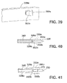
- FIG. 39 is a perspective view of an actuation tip of another stapler in accordance with the disclosure.
- FIG. 40 is a top view of a stapler incorporating the actuation tip of FIG. 39 with the staple deployed, but not released from the staple chamber.
- FIG. 41 is a top view of the stapler of FIG. 40 , after the staple has been pushed forward to spread apart the actuation tips.
- FIG. 42 is a cut-away side view of a stapler with another embodiment of a release mechanism for releasing a staple from a stapler of the present disclosure.
- FIG. 43 is a perspective view of an expansion tip of the stapler of FIG. 42 .
- FIG. 44 is a cut-away side view of the stapler of FIG. 42 with the staple closed, but not released from the stapler.
- FIG. 45 is a transverse cross-section view along line 45 - 45 of FIG. 44 with the actuation tip that was cut away from FIGS. 42 and 44 .
- FIG. 46 is an alternative embodiment of the stapler of FIGS. 42-44 , shown in a transverse cross-section view along line 46 - 46 of FIG. 44 with the actuation tip that was cut away from FIGS. 42 and 44 .
- FIG. 47 is an outline of a method of using a vascular closure system in accordance with the disclosure.
- FIGS. 1-10 show cross-sectional views of body tissue 100 with a vessel 102 disposed therein.
- FIG. 1 shows a procedural device 108 , such as a balloon catheter, disposed partially within a lumen 104 of vessel 102 .
- the distal end of procedural device 108 is shown riding along a guidewire 110 .
- Procedural device 108 passes through a procedural sheath 106 , which maintains access to lumen 104 through a tissue track 101 in tissue 100 and arteriotomy 132 in the wall of vessel 102 .
- procedural device 108 is removed from vessel 102 and tissue track 101 via procedural sheath 106 , as shown in FIG. 2 .
- Guidewire 110 remains in place partially disposed within lumen 104 of vessel 102 .
- procedural sheath 106 is removed from lumen 104 , arteriotomy 132 , and tissue track 101 , leaving guidewire 110 in place.
- tissue track 101 and arteriotomy 132 are shown in FIG. 3 as being maintained in an open state, in practice, tissue track 101 and arteriotomy 132 will tend to at least partially close around guidewire 110 when procedural sheath 106 is removed.
- a vascular closure system of the disclosure is used to close arteriotomy 132 , as follows.
- a dilator 112 is guided along guide wire 110 into tissue track 101 .
- a pair of stabilization wire guides 114 are provided with dilator 112 .
- Stabilization wire guides 114 ride along an outside surface of dilator 112 .
- Distal portions of stabilization wire guides 114 are inserted into respective openings 116 in dilator 112 so that stabilization wire guides 114 advance with dilator 112 into tissue track 101 .
- dilator 112 and stabilisation wire guides 114 are advanced farther along guidewire 110 into lumen 154 .
- dilator 112 opens tissue track 101 and arteriotomy 132 .
- intraluminal position of the device may be indicated by blood entering the device through an inlet port positioned within the vessel lumen, the blood flowing through a passageway in the device, and the blood finally emitting from the device as a visible “flashback” out of art exit port external to the patient.
- the device may have an enlarged physical stop for abutting against the external wall of the blood vessel to provide a tactile indication of the position of the device with respect to the vessel wall.
- Dilator 112 is advanced farther into lumen 104 of vessel 102 while stabilization wire guides 114 are restricted from movement. This relative movement between dilator 112 and stabilization wire guides 114 causes the distal portions of stabilization wire guides 114 to be exposed or released from openings 116 in dilator 112 .
- Stabilization wire guides 114 are manipulated or deployed to form retention feet 115 in the distal portions thereof.
- Retention feet 118 may be formed in various ways as would be known to those of ordinary skill in the art, for example, the ways described in FIGS. 49-57 of U.S. Pat. No. 6,767,356 to Kanner et al., the entire disclosure of which is incorporated herein by reference.
- FIGS. 5-10 show a pair of stabilization wire guides 114 aligned along the axis of vessel 102 .
- a pair of stabilization wire guides 114 will typically be aligned transverse to the axis of vessel 102 and positioned at the ends of the slit that naturally forms generally perpendicular to the length of the vessel when arteriotomy 132 is formed in the wall of vessel 102 , as described in the above-mentioned Kanner '356 patent.
- Such transverse alignment of stabilization wire guides 114 within arteriotomy 132 is especially typical when stabilization wire guides 114 are spread apart by closure system 122 as described below.
- FIGS. 7 and 8 guidewire 110 and dilator 112 are removed from lumen 104 , arteriotomy 132 and tissue track 101 , leaving only stabilization wire guides 114 extending through tissue track 101 and arteriotomy 132 into lumen 104 .
- Stabilization wire guides 114 provide guidance for insertion of a closure system.
- a closure system 122 is slidably mounted onto stabilization wire guides 114 so that a distal portion of closure system 122 can ride along stabilization wire guides 114 to a location within tissue track 101 spaced proximally from vessel 102 .
- Closure system 122 includes an elongate stapler 128 carried slidably within a center tube 124 .
- Two or more relatively short side tubes 126 are coupled parallel to the distal portion of center tube 124 on opposing sides thereof.
- center tube 124 may be 30 cm long and side tubes may be 2 cm long.
- Center tube 124 and side tubes 126 will separate stabilization wire guides 114 when closure system 122 is advanced there along. Separating stabilization wire guides 114 applies tension along the long axis of slit-shaped arteriotomy 132 such that tissue along both sides of arteriotomy 132 tends to come together for engagement by a closure system, as described in the above-mentioned Kanner '356 patent.
- FIG. 11 shows a side view of an embodiment of the present disclosure.
- Vessel 102 is shown in longitudinal cross-section and tissue 100 has been excluded for convenience of illustration.
- closure system 122 With retention feet 118 deployed within lumen 104 of vessel 102 , closure system 122 is advanced toward arteriotomy 132 until the distal end of closure system 122 is stopped extraluminally at a preset distance from retention feet 118 .
- the distance between the distal end of closure system 122 and retention feet 118 may be preset in a mechanism (not shown) coupled to the proximal ends of stabilization wire guides 114 and center tube 124 .
- stapler 128 may be advanced distally within center tube 124 to expose a pair of actuation tips 129 and a staple 130 held there between.
- two staple tips 139 of staple 130 are expanded laterally and are extended distally from between actuation tips 129 to pierce vessel tissue on either side of arteriotomy 132 .
- side tubes 126 and stabilization wire guides 114 are described as being disposed on “sides” of stapler 128
- lateral expansion of staple tips 139 means the tips expand toward the top and bottom of stapler 128 . It will be understood by one of skill in the art that top, bottom and side are terms used only to assist the reader in understanding the relative positions of the components of the disclosure.
- Staple tips 139 are then closed to gather or pucker the engaged tissue, thus closing arteriotomy 132 .
- Staple 130 is released from stapler 128 to remain embedded in vessel 102 . Described further below are several embodiments of the disclosure that are suitable for releasing a staple from a stapler. Stabilization wire guides 114 and closure system 122 , except for staple 130 , are then removed from the body, as shown in FIG. 14 . Actuation tips 129 and staple 130 may be conventional as would be known to one of ordinary skill in the art, such as the actuating tip portion of a stapler and the staple shown in FIGS. 67-71 of the above-mentioned Kanner '356 patent.
- FIGS. 15-19 show an embodiment of a stapler 228 of the present disclosure.
- FIG. 15 is a cut-away perspective view of stapler 228 .
- FIG. 47 outlines a method 1000 of using staplers in accordance with the disclosure, including stapler 228 .
- Stapler 228 includes an elongate hollow shaft 227 .
- At the distal end of hollow shaft 227 is a pair of flat-sided, opposing actuation tips 229 (only one tip 229 a is shown in FIGS. 15-17 ).
- actuation tips 229 face each other and are spaced apart to provide a passageway for slidably receiving a flat distal portion of an elongate driver 240 , and to provide an open-sided staple chamber for holding at least a proximal portion of a staple 230 .
- the open sides of the staple chamber are oriented toward the top and bottom of stapler 228 .
- staple chamber 345 in FIG. 24 see staple chamber 345 in FIG. 24 .
- the distal end of driver 240 has a pair of tip edges 242 arranged to form an axially symmetrical pointed tip for abutment against a proximal end of staple 230 .
- An anvil 250 for deforming or deflecting staple 230 is fixed within the staple chamber.
- Single anvil 250 may be dimensioned to substantially span the staple chamber, as illustrated in FIG. 46 , and may be integrally formed with or attached to actuation tip 229 a , without being affixed to opposite actuation tip 229 b .
- anvil 250 may be formed by two mating anvil halves, each anvil half being integral with or attached to actuation tip 229 a or 229 b , respectively.
- Driver 240 extends proximally within hollow shaft 227 to a handle (not shown) wherein a mechanism may be manually operated to move driver 240 within hollow shaft 227 , as will be understood by one of ordinary skill in the art of medical stapling devices.
- driver 240 and hollow shaft 227 may each be about 30 cm in length.
- Staple 230 includes two legs respectively having proximally-located expansion bends 236 a and 236 b connected by a closure bend 237 .
- the two legs of staple 230 respectively have staple expansion ramps 234 a and 234 b , optional staple tissue stops 238 a and 238 b , and staple tips 239 a and 239 b . See step 1010 in FIG. 47 .
- the distal portion of stapler 228 is positioned at a preset distance from an arteriotomy, as shown with respect to stapler 128 in FIG. 11 . See also step 1020 in FIG. 47 .
- Driver tip edges 242 a and 242 b abut expansion bends 236 a and 236 b at the proximal end of staple 230 .
- Staple tips 239 a and 239 b extend from the distal end of hollow shaft 227 , even prior to the initiation of deployment of staple 230 from stapler 228 .
- Driver 240 is advanced distally within hollow shaft 227 such that driver tip edges 242 a and 242 b push staple 230 distally in the staple chamber formed between actuation tips 229 such that staple expansion ramps 234 a and 234 b ride along, and are forced apart by anvil 250 .
- the separation of expansion ramps 234 a and 234 b causes the legs of staple 230 to separate and extend laterally through the open sides, i.e. top and bottom of the chamber along the distal portion of hollow shaft 227 .
- expansion bends 236 a and 236 b are forced open and staple tips 239 a and 239 b separate from each other, as shown in FIG. 16 . See also step 1030 in FIG. 47 .
- expansion bends 236 a and 236 b as they are opened may exceed the elastic limits of the staple material such that at least some plastic deformation may occur.
- staple 230 is advanced distally such that staple lips 239 a and 239 b pierce vessel 102 to engage vessel tissue on either side of arteriotomy 132 . See step 1040 in FIG. 47 .
- Stabilization wire guides 114 aid in centering, or stabilizing closure system 122 over arteriotomy 132 , as shown in FIGS. 11 and 12 .
- the expanded distance between tips 239 a and 239 b more than, spans arteriotomy 132 , as shown with respect to staple 130 in FIG. 12 .
- staple tissue stops 238 a and 238 b help prevent tips 239 a and 239 b respectively from fully penetrating the wall of vessel 102 and entering lumen 104 .
- staple closure bend 237 abuts anvil 250 , and staple expansion ramps 234 a and 234 b clear anvil 250 , permitting at least some elastic recovery of staple expansion bends 236 a and 236 b . See step 1050 in FIG. 47 .
- Driver tip edges 242 a and 242 b force closure bend 237 against anvil 250 , thereby deforming closure bend 237 into a more open angle.
- the deformation of closure bend 237 may exceed the elastic limits of the staple material such that at least some plastic deformation may occur.
- Opening closure bend 237 causes the legs of staple 230 to pivot in opposite directions around the apex of closure bend 237 such that staple tips 239 a and 239 b move toward each other, as shown in FIG. 17 .
- staple tips 239 c and 239 b are forced together, the vessel tissue between them is gathered or puckered, thereby closing arteriotomy 132 .
- staple tips 239 a and 239 b may approach, or touch, or even cross over each other as shown in FIGS. 13 , 14 and 17 , depending upon the amount of tissue between the tips,
- FIGS. 31 and 32 are top sectional views of stapler 228 , with staple 230 being omitted for clarity.
- Driver 240 may include a distal wedge 244 , or distally-facing wedges 244 a and 244 b , disposed proximally from driver distal edge 242 .
- Wedges 244 a and 244 b extend laterally outward from side surfaces 246 a and 246 b of driver 240 in the direction of actuation tips 229 a and 229 b , respectively.
- actuation tips 229 a and 229 b include proximally-facing ramps 270 a and 270 b , respectively, disposed proximally from anvils 250 a and 250 b.
- driver 240 is moved distally within hollow shaft 227 such that closure bend 237 is opened to force staple tips 239 a and 238 b together.
- wedges 244 a and 244 b push against and slide along ramps 270 a and 270 b , respectively, thereby causing actuation tips 229 a and 229 b to spread apart, from each other, as shown in FIG. 32 .
- actuation tips 229 a and 229 b spread apart from each other, a gap 272 is formed between anvil 250 a of actuation tip 229 a and anvil 250 b of actuation tip 229 b , thereby releasing staple 230 from the staple chamber of stapler 228 . See step 1060 in FIG. 47 .
- Staple 230 is thus permitted to remain in place, closing the arteriotomy as stapler 228 , including hollow shaft 227 , actuation tips 229 a and 229 b and driver 240 , is removed from the body.
- stapler 228 including hollow shaft 227 , actuation tips 229 a and 229 b and driver 240 , is removed from the body.
- driver 240 it is important to have close dimensional tolerances between anvil 250 and ramps 270 a and 270 b , and between driver distal edge 242 and wedges 244 a and 244 b to ensure coordination between staple deployment and release.
- FIGS. 33 and 34 are top sectional views of another stapler 228 ′, with staple 230 being omitted for clarity.
- driver 240 ′ includes proximally-facing wedges 244 a ′ and 244 b ′ disposed proximally from driver distal edge 242 ′, and actuation tips 229 a ′ and 229 b ′ include distally-facing ramps 270 a ′ and 270 b ′, respectively, disposed proximally from anvils 250 a and 250 b.
- FIG. 33 shows stapler 228 ′ after staple 230 has been deployed, but not released.
- driver 240 ′ In order to release the staple from anvils 250 a ′, 250 b ′, driver 240 ′ is moved proximally such that wedges 244 a ′ and 244 b ′ engage ramps 270 a ′ and 270 b ′, respectively. Ramps 270 a ′ and 270 b ′ ride up wedges 244 a ′ and 244 b ′, thereby forcing actuation tips 229 a ′ and 229 b ′ apart from each other and releasing the staple, as shown in FIG. 34 .
- This embodiment is less sensitive to dimensional tolerances than the embodiment shown in FIGS. 31 and 32 because staple 230 is fully deployed before driver 240 ′ is moved proximally to release staple 230 .
- release mechanisms 280 a and 280 b are provided coupled to each side of driver 240 ′′.
- FIGS. 35 and 36 are side sectional views of stapler 228 ′′.
- Release mechanisms 280 a and 280 b each includes a base 282 a and 282 b , a pair of arms 284 a/b and 285 a/b , and hooks 286 a/b and 287 a/b extending laterally outward from arms 284 a/b , 285 a/b , respectively.
- Actuation tips 229 a ′′ and 229 b ′′ (only actuation tip 229 a ′′ is shown in FIGS.
- FIG. 35 shows stapler 228 ′′ with staple 230 in the pre-deployment configuration as stapler 228 ′′ is being delivered to the arteriotomy site.
- Arms 284 a/b and 285 a/b of release mechanisms 280 a/b are resiliently compressed toward each other by sidewalks 292 a/b and 293 a/b of actuation tips 229 a ′′ and 229 b ′′.
- hooks 286 a/b and 287 a/b arrive at notches 288 a/b and 289 a/b .
- Sidewalls 292 a/b and 293 a/b no longer compress arms 284 a/b and 285 a/b as hooks 286 a/b and 287 a/b resiliently extend into notches 285 a/b and 289 a/b , respectively, as shown in FIG. 36 .
- driver 240 ′′ is moved proximally, thereby also moving release mechanisms 280 a and 280 b proximally, as shown in FIG. 37 .
- release mechanisms 280 a and 280 b are moved proximally, hooks 286 a/b and 287 a/b ride up ramps 290 a/b and 291 a/b .
- This motion causes actuation tips 229 a ′′ and 229 b ′′ to spread apart, thereby providing a gap 272 between anvils 250 a and 250 b through which staple 230 may pass, as shown in the top sectional view of stapler 228 ′′ shown in FIG. 38 .
- staplers 228 , 228 ′ and 228 ′′ may include a single anvil 250 extending from one actuation tip toward the other actuation tip instead of a pair of anvils 250 a and 250 b . Similar to stapler 228 ′ above, stapler 228 ′′ is less sensitive to dimensional tolerances because staple 230 is fully deployed before driver 240 ′′ is moved proximally to release staple 230 .
- Staple 230 may comprise a biocompatible metal such as nitinol (TiNi), stainless steel, tantalum, or titanium. Magnesium or an alloy thereof may also be used to make staple 230 , and such materials also have the potential advantage of being bioabsorbable.
- a biocompatible metal such as nitinol (TiNi), stainless steel, tantalum, or titanium. Magnesium or an alloy thereof may also be used to make staple 230 , and such materials also have the potential advantage of being bioabsorbable.
- Staple 230 may also be formed from various filled or unfilled rigid or semi-rigid polymers such as liquid crystal polymer (LCP), polyamide, polycarbonate, poly-etheretherketone (PEEK), polysulfone, polyvinylidene fluoride (PVDF), and may include bioabsorbable or biodegradable polymeric materials such as polycaprolactone, poly(glycolide) (PGA), poly(L-lactide) (PLLA) and poly(D,L-lactide) (PLA).
- LCP liquid crystal polymer
- PEEK poly-etheretherketone
- PVDF polysulfone
- PVDF polyvinylidene fluoride
- bioabsorbable or biodegradable polymeric materials such as polycaprolactone, poly(glycolide) (PGA), poly(L-lactide) (PLLA) and poly(D,L-lactide) (PLA).
- staple 230 may formed of a rigid thermoplastic in an injection mold.
- Staple 230 may be opened by elastic and/or plastic deformation of expansion bends 236 a and 236 b and may be closed by elastic and/or plastic deformation of closure bend 237 .
- Combined elastic and plastic deformation refers to a staple that has had its shape changed to exceed the elastic region of its material properties, so the staple will only tend to return part way to its previous shape.
- FIGS. 20-24 show an embodiment of a stapler 328 of the present disclosure.
- FIG. 20 is a cut-away perspective view of stapler 328 .
- Stapler 328 includes an elongate hollow shaft 327 having, at its distal end, a pair of flat opposing actuation tips 329 (only one tip 329 a is shown in FIGS. 20-23 ) spaced apart to provide an open-sided chamber for holding a staple 330 .
- An elongate driver 340 is slidably disposed within hollow shaft 327 and has a flat distal portion slidingly disposed within the chamber. The distal end of driver 340 may be shaped, e.g.
- Anvil 350 for retaining and deflecting staple 330 may extend substantially across the staple chamber and may be integral with or attached to actuation tip 329 a , without being affixed to opposite actuation tip 329 b .
- anvil 350 may be formed by two mating anvil halves 350 a and 350 b , each anvil half being integral with or attached to actuation tip 329 a or 329 b , respectively, Only one anvil 350 a is shown in FIGS. 20-23 .
- Driver 340 extends proximally within the hollow shaft to a handle (not shown) wherein a mechanism may move the driver 340 relative to the hollow shaft and actuation tips 329 , as described above with respect to stapler 228 .
- Stapler 328 includes a staple 330 made according to a material and a process such that it lends to elastically return to a closed shape, as will be described with respect to FIGS. 20-22 .
- Staple 330 may be made of nitinol or other suitable elastic or pseudoelastic shape memory alloy (SMA) that may be heat set in a relaxed or neutral configuration such as the closed configuration shown in FIGS. 20 and 22 .
- SMA elastic or pseudoelastic shape memory alloy
- Staple 330 is carried within stapler 328 and staple 330 may be heat set in a pre-formed or relaxed configuration with staple tips 339 a and 339 b crossed over each other, or barely touching each other, or spread slightly apart as shown in FIG. 20 .
- Staple tips 339 a and 339 b extend from the distal end of hollow shaft 327 , even prior to the initiation of deployment of staple 330 from stapler 328 .
- Staple 330 includes two legs connected by a proximal bend. The legs respectively have staple expansion ramps 334 a and 334 b , optional staple tissue stops 338 a and 338 b , and staple tips 339 a and 339 b.
- driver 340 When stapler 328 is in the proper position with respect to vessel 102 , driver 340 is advanced distally within hollow shaft 327 such that the driver distal end pushes staple 330 distally in the staple chamber between expansion tips 329 , and staple expansion ramps 334 a / 334 b ride along, and are forced apart by anvil 350 , as shown in FIG. 21 .
- the separation of expansion ramps 334 a and 334 b causes the legs of staple 330 to separate and extend laterally from the open sides of the staple chamber in the distal end of hollow shaft 327 .
- staple tips 339 a and 339 b are spread apart, the proximal staple bend is opened up, and staple 330 is advanced distally such that staple-tips 339 a and 339 b pierce the vessel wail (not shown) to engage vessel tissue on either side of arteriotomy 132 (not shown).
- staple 330 is advanced distally such that staple-tips 339 a and 339 b pierce the vessel wail (not shown) to engage vessel tissue on either side of arteriotomy 132 (not shown).
- expansion ramps 334 a and 334 b clear anvil 350 , and the elastic or shape memory property of the proximal bend of staple 330 causes staple tips 339 a and 339 b to close toward each other.
- staple tips 339 a and 339 b draw together, the vessel tissue between them is gathered or puckered, thereby closing the arteriotomy.
- staple tips 339 a and 339 b may again approach, or touch, or even cross over each other, depending upon the pre-formed staple configuration and the amount of tissue gathered between the tips.
- FIG. 23 shows a perspective view of actuation tip 329 a , including anvil 350 and side rails 360 a and 361 a, which terminate proximally of the distal ends of expansion tips 329 a and 329 b .
- Side rails 360 a and 361 a abut side rails 360 b and 361 b of expansion tip 329 b , as shown in FIG.
- passageway 362 there between for slidably receiving the fiat distal portion of driver 340 .
- the flat surfaces of actuation tips 229 form open-sided staple chamber 345 , which contains anvil 350 .
- only one of the expansion tips includes the side rails and the side rails abut against the flat surface of the other expansion tip.
- the side rails may be thicker than in an embodiment with side rails on each expansion tip in order to create the appropriately-sized passageway 362 and staple chamber 345 .
- staple 330 must clear anvils 350 a/b in order to be released from stapler 328 . Such, release can be accomplished by the mechanisms and methods described above with respect to FIGS. 31-45 .
- anvils 350 a and 350 b may include proximally-facing ramps 352 a and 352 b , as shown in FIGS. 20-22 and 39 - 44 . After expansion ramps 334 a and 334 b clear anvils 350 a/b , and the elastic or shape memory property of staple 330 causes staple tips 339 a and 339 b to close toward each other, as shown in FIG. 22 .
- driver 340 may be held in place longitudinally as proximally-directed force is applied to hollow shaft 327 .
- driver 340 holds staple 330 against, the proximally-facing surfaces of anvils 350 a and 350 b , and holds staple tips 339 a and 339 b in the vessel wall about the arteriotomy. In this way, actions taken to release staple 330 from stapler 328 do not pull proximally on staple 330 once it is engaged with the tissue of the vessel wall.
- anvils 350 a and 350 b are ramps 352 a and 352 b , respectively.
- proximal movement of hollow shaft 327 forces ramps 352 a and 352 b to separate around the proximal bend of staple 330 , thereby causing actuation tips 329 a and 329 b to spread apart, creating a gap 372 between anvils 350 a and 350 b , as shown in FIG. 41 .
- anvils 350 a/b clear staple 330 , which is thereby released from stapler 328 .
- stapler 328 releases deployed staple 330 by forcing actuation tips 329 a and 329 b to spread apart by engaging ramps 352 a and 352 b with staple 330 itself. Hollow shaft 327 and driver 340 can then be removed from the body.
- stapler 428 includes a staple 430 that is similar or identical to staple 330 described above and is made of nitinol or other suitable elastic or pseudoelastic shape memory alloy (SMA).
- staple 430 of the present embodiment can also be similar in shape and material properties to staple 230 shown and described with respect to FIGS. 15-19 .
- Stapler 428 further includes actuation tips 429 a/b .
- actuation tip 429 a is shown in FIGS. 42-44 for ease of viewing, however, it would he understood by one of ordinary skill in the art that actuation tip 429 b is a mirror image of actuation tip 429 a , as shown in FIG. 43 .
- Actuation tip 429 a includes anvil 450 a similar to anvil 350 a described with respect to FIGS. 20-24 .
- Actuation tip 429 a further includes first and second laterally opposed side ramps 454 a and 456 a disposed abutting the distal end of anvil 450 a.
- Stapler 428 further includes an elongate driver 440 and a staple 430 , similar or identical to driver 340 and staple 330 described above with respect to FIGS 20 - 24 .
- Staple 430 includes staple expansion ramps 434 a and 434 b.
- driver 440 is advanced within hollow shaft 424 such that the driver distal end pushes staple 430 distally in the staple chamber between expansion tips 429 a/b such that staple expansion ramps 434 a and 434 b ride along, and are forced apart by anvil 450 a/b , as shown in FIG. 42 .
- the separation of expansion ramps 434 a and 434 b causes the legs of staple 430 to separate and extend laterally from the open sides of the staple chamber in the distal end of hollow shaft 424 .
- staple, tips 439 a and 439 b are spread apart and staple 430 is advanced distally such that staple tips 439 a and 439 b pierce the vessel wail to engage vessel tissue on either side of arteriotomy 132 .
- the forces that act to spread apart staple tips 439 a and 439 b do not act orthogonally to simultaneously spread apart actuation tips 429 a and 429 b .
- expansion ramps 434 a and 434 b clear anvil 450 a/b , and staple tips 439 a and 439 b close toward each other to gather or pucker the engaged tissue, thus closing arteriotomy 132 .
- Staple 430 may be released from stapler 428 simultaneously with or subsequently to deployment of staple 430 to close arteriotomy 132 .
- Driver 440 may be held in place longitudinally as proximally-directed force is applied to hollow shaft 424 to release staple 430 .
- driver 440 holds staple 430 in the closed configuration about the arteriotomy. That is, actions taken to release staple 430 from stapler 428 do not pull proximally on staple 430 once it is engaged with the tissue of the vessel wall. As can be seen in FIGS.
- Hollow-shaft 424 may then continue to be moved proximally over driver 440 , such that the gap formed between anvils 450 a/b clears staple 430 , which is thereby released from stapler 428 .
- stapler 428 releases deployed staple 430 by forcing actuation tips 429 a and 429 b to spread apart by the closing force of staple 430 acting against side ramps 454 a/b and 456 a/b .
- Hollow shaft 424 and driver 440 can then be removed from the body.
- the closing force of staple 430 may be an inherent elastic, resilient or shape memory property similar to that of staple 330 .
- the closing force of staple 430 may be the result of moving driver 440 within hollow shaft 424 to plastically deform staple 430 into a closed configuration, as described above with respect to staple 230 shown in FIGS. 15-19 .
- stapler 428 may include a single anvil extending from one actuation tip toward the other actuation tip instead of a pair of anvils 450 a and 450 b.
- closure system 122 may be advanced along stabilization wire guides 114 through tissue track 101 without a sheath placed in tissue track 101 .
- any one of staplers 128 , 228 , 328 , or 428 may be slidably disposed within center tube 124 and may be advanced through tissue track 101 together with center tube 124 . Tips of staples 130 , 230 , 330 , and 430 extend distally from the respective staplers, even prior to initialing deployment of the staples.
- closure system 122 While closure system 122 is being advanced to the arteriotomy site, it may be desirable to protect staple 130 , 230 , 330 , or 430 against possible damage from tissue track 101 , or conversely, it may be desirable to protect tissue track 101 against possible injury from staple 130 , 230 , 330 , or 430 .
- FIGS. 25 and 26 show an embodiment of a center tube 424 having at its distal end at least two opposing longitudinal slots aligned with the side openings in the staple chamber of staplers 128 , 228 , 328 , or 428 , as described above.
- Center tube 424 further includes a pair of opposing corners 427 defined where each slot meets the distal opening of center tube 424 .
- the legs of staples 130 , 230 , 330 , or 430 can expand laterally from staplers 128 , 228 , 328 , or 428 into the distal slots in center tube 424 .
- FIGS. 25 and 26 show an embodiment of a center tube 424 having at its distal end at least two opposing longitudinal slots aligned with the side openings in the staple chamber of staplers 128 , 228 , 328 , or 428 , as described above.
- Center tube 424 further includes a pair of opposing corners 427 defined where each slot meets the distal opening of center tube 424
- the center tube lacks distal slots such that staplers 128 , 228 , 328 , or 428 must be advanced until staples 130 , 230 , 330 , or 430 held in the staple chamber are outside of the center tube before staple deployment is initiated.
- the center tube must be spaced away from vessel 102 a sufficient distance such that, during deployment, the stapler can be advanced to the point where a staple can expand laterally without binding on the center tube.
- center tube 424 is provided with an inwardly tapered or pinched distal portion 425 , which at least partially covers or guards the staple tips.
- pinched distal portion 425 brings together corners 427 in center tube 424 .
- center tube 424 is advanced along stabilization wire guides 414 via side lubes 426 .
- Pinched distal portion 425 protects staple 430 from damage while being advanced through tissue track 101 , or protects tissue track 101 from injury by staple 430 passing there through.
- expansion tips 429 a and 429 b are advanced distally, opening pinched distal portion 425 and spreading the distal ends of the distal slots in center tube 424 , as shown in FIG. 26 .
- Staple 430 is then opened and closed around the arteriotomy as described in the embodiments above.
- staple 430 may be deployed without advancing the distal end of the stapler beyond the distal end of center tube 424 .
- the opposing legs of staple 430 are permitted to expand transversely from the open sides of the staple chamber and to spread through the center tube slots, which are aligned with the open sides of the staple chamber.
- the staple may be protected using a frangible cap 574 , as shown in FIGS. 27 and 28 .
- Frangible cap 574 is fixed to and covers a distal portion of a center tube 524 , and includes a planar portion 576 extending across a distal opening of center tube 524 .
- Frangible cap 574 may be a biocompatible polymeric membrane or a biocompatible metallic foil, and may include perforations, grooves or other disruptions that define tear lines within the cap.
- Frangible cap 574 may comprise one or more polymers such as polyurethane, polyester or polystyrene.
- More resilient polymers for making frangible cap 574 may comprise natural or synthetic rubber such as butadiene/acrylonitrile copolymers, copolyesters, ethylene vinylacetate (EVA) polymers, ethylene/acrylic copolymers, ethylene/propylene copolymers, fluorosilicone, latex, polyalkylacrylate polymers, polybutadiene, polybutylene, polyethylene, polyisobutylene, polyisoprene, polyurethane, silicone, styrenebutadiene copolymers, styrene-ethylene/butylene-styrene, thermoset elastomer, thermoplastic elastomer and combinations of the above.
- natural or synthetic rubber such as butadiene/acrylonitrile copolymers, copolyesters, ethylene vinylacetate (EVA) polymers, ethylene/acrylic copolymers, ethylene/propylene copolymers, fluorosilicone, latex, poly
- Polymeric frangible cap 574 may be formed by various methods including casting, compression molding, liquid injection molding, reaction injection molding (RIM), resin transfer molding (RTM), and thermoplastic injection molding. Polymeric frangible cap 574 may be molded of soft foam, solid elastic material, or a combination thereof.
- Frangible cap 574 separates staple 530 from tissue track while center tube 524 is advanced through a tissue track along stabilization wire guides 514 via side tubes 526 .
- a stapler 528 carrying staple 530 is advanced distally through center tube 524 such that the staple tips and/or the distal end of stapler 528 penetrate or fracture frangible cap 574 , as shown in FIGS. 28 and 44 .
- FIG. 28 and 44 In the embodiment shown in FIG.
- Staple 530 is then opened, engaged and closed around the arteriotomy as described in the embodiments above.
- frangible cap 574 ′ tears into a configuration wherein a generally planar pledget 578 separates from the remainder of frangible cap 574 ′, which stays fixed to center tube 524 .
- Pledget 578 is carried on the distal end of stapler 528 and is implanted with staple 530 to aid in closing arteriotomy 132 , as described in U.S. Published Patent Application Number 2004/0093024 A1 to Lousararian et al., the entire disclosure of which is incorporated herein by reference.
- Pledget 578 may comprise a part of, or substantially all of planar portion 576 of frangible cap 574 ′. Pledget 578 may have circumferentially spaced notches for frictional engagement with, and centering between the legs of staple 530 , as described in the above-referenced Lousararian publication.
- pledget 578 may promote hemostasis by stemming the flow of blood from arteriotomy 132 that is being closed by staple 530 .
- pledget 578 may be either bio-resorbable or non-resorbable, and may include physiologically active agents such as Cefazolin, chlorhexidine, fusidic acid, Novobiocin, polymyxin B, rifampicin, silver or a silver compound, or tetracycline for inhibition of infection.
- Alternative physiologically active agents may include collagen or derivatives thereof, heparin, or phosphorylcholine for promotion of extraluminal clotting.
- physiologically active agents may be coated onto, absorbed within, or otherwise incorporated into the material of pledget 578 .
Abstract
A closure device for an arteriotomy includes an elongate tube having a distal opening. The elongate tube has least two opposing longitudinal slots and a pair of opposing corners defined where each slot meets the distal opening. A staple is disposed within the tube, the staple having at least two opposing legs aligned with the at least two slots. Each slot is pinched together adjacent the distal opening such that the opposing corners of each slot converge to cover the tip of the respective staple leg to guard the staple tips against contact with the tissue track. The corners of each slot are separable to permit the respective staple leg to pass there between.
Description
The present disclosure relates to system and method for closing an opening in a vessel wall after a medical procedure, and in particular, to a system and method for closing a puncture arteriotomy after an intra-luminal procedure such as catheterization.
Catheters/catheterization procedures for diagnosis or treatment of cardiovascular and/or peripheral vascular diseases are well known, and typically involve the Seldinger technique to make insertions through layers of tissue and through a wall of the femoral artery. After a diagnostic or interventional catheterization, the arteriotomy puncture formed by the catheter or introducer sheath must be closed. The puncture opening in the artery typically ranges from 5 French (0.0655 inch, 1.67 mm) such as for a diagnostic angiography procedure to as large as 30 French (0.393 inch, 10.00 mm) for an interventional procedure such as implanting an inferior vena cava (IVC) filter. Traditionally, intense pressure has been applied to the puncture site for at least 30-45 minutes after removal of the catheter. Patients who have had a femoral artery puncture are then required to remain at bed rest, essentially motionless and often with a heavy sandbag placed on their upper legs, for several hours to ensure that the bleeding has stopped. Other approaches include the use of a thrombotic or collagen plug or slurry, and/or other suturing methodologies for sealing the puncture. Also known are systems and methods for blind delivery, viz., without direct visualization, of a staple or clip to gather and hold together sides of the arteriotomy. However, these closure systems typically deliver, or perform the closure modality via a sheath, which holds the tissue track open. Therefore, there is a need for a low-profile closure system.
A method for closing an arteriotomy in a wall of a vessel of a body after an intra-luminal procedure is disclosed. The terms “distal” and “proximal” are used in the specification with respect to a position or direction relative to the treating clinician. “Distal” or “distally” are a position distant from or in a direction away from the clinician. “Proximal” and “proximally” are a position near or in a direction toward the clinician. The method may be practiced without a sheath in place in the tissue track. A guidewire from the intra-luminal procedure remains in the vessel or is replaced with another guidewire. A procedural sheath, if used, is removed from the patient. A dilator and a guiding system are advanced together along the guidewire into the body tissue, through the arteriotomy and are into the vessel lumen. The guiding system includes at least two stabilization wire guides, each stabilization wire guide having a deployable retention foot disposed at a distal portion thereof. The guiding system is deployed within the vessel lumen such that the retention feet can be pulled back against an inner surface of the vessel wall. The guidewire and dilator are withdrawn from the lumen and the body tissue, leaving only the guiding system in place. A closure system is advanced along the guiding system to a position proximal to the arteriotomy. The closure system includes a center tube housing a stapler, the center tube having at least two side tubes for riding along the stabilization wire guides. The stapler is then activated to close the arteriotomy and the guiding system and closure system are withdrawn from the lumen and the body.
An embodiment of the stapler includes an elongate hollow shaft having at its distal end a pair of opposing actuation tips that define a staple chamber there between. An anvil extends into the staple chamber from one of the actuation lips to retain and deform a staple. An elongate driver is slidably disposed in the hollow shaft. A staple includes a pair of opposing legs proximally coupled by a bend and having an expansion ramp extending from each leg toward the other leg. The staple may be opened and/or closed by plastic or elastic deformation. When the closure system is disposed adjacent to the arteriotomy, an operator mechanism moves the driver longitudinally relative to stapler shaft such that the driver advances the staple between the actuation tips. The staple expansion ramps ride and spread apart along the anvil, thereby opening the staple. As the operator continues to push the driver longitudinally, the staple expansion ramps clear the anvil, permitting the staple to close. In an embodiment of the stapler, the driver closes the staple by deforming the staple bend against the anvil. In another embodiment, of the stapler, the staple is elastically self-closing. A staple release mechanism is actuated to spread the actuation tips apart, creating a gap through which the staple is released from the anvil.
In an embodiment of the closure system, a distal portion of the center tube is pinched such that it separates the staple tips from the tissue track during delivery to the arteriotomy site. When the staple is deployed, the staple spreads the pinched portion apart.
In another embodiment of the closure system, a frangible cap is disposed over the distal opening of the center tube. The frangible cap separates the staple tips from the tissue track during delivery to the arteriotomy site. When the staple is deployed, the staple perforates or fractures the frangible cap. Optionally, a portion of the frangible cap tears away from the center tube to form a pledget that is retained against the arteriotomy by the staple.
The foregoing and other features and advantages of the present disclosure will be apparent from the following description of the disclosure as illustrated in the accompanying drawings. The accompanying drawings, which are incorporated herein and form a part of the specification, further serve to explain the principles of the disclosure and to enable a person skilled in the pertinent art to make and use the disclosure. The drawings are not to scale.
Low Profile Guiding System
Specific embodiments of the present disclosure are now described with reference to the figures, where like reference numbers indicate identical or functionally similar elements. The present disclosure is directed to a device and method for closing an arteriotomy after a procedure in which a vessel was punctured to gain access to the vessel lumen. FIGS. 1-10 show cross-sectional views of body tissue 100 with a vessel 102 disposed therein. FIG. 1 shows a procedural device 108, such as a balloon catheter, disposed partially within a lumen 104 of vessel 102. The distal end of procedural device 108 is shown riding along a guidewire 110. Procedural device 108 passes through a procedural sheath 106, which maintains access to lumen 104 through a tissue track 101 in tissue 100 and arteriotomy 132 in the wall of vessel 102.
As the intra-luminal procedure, such as balloon angioplasty, is completed, procedural device 108 is removed from vessel 102 and tissue track 101 via procedural sheath 106, as shown in FIG. 2 . Guidewire 110 remains in place partially disposed within lumen 104 of vessel 102. As shown in FIG. 3 , procedural sheath 106 is removed from lumen 104, arteriotomy 132, and tissue track 101, leaving guidewire 110 in place. Although tissue track 101 and arteriotomy 132 are shown in FIG. 3 as being maintained in an open state, in practice, tissue track 101 and arteriotomy 132 will tend to at least partially close around guidewire 110 when procedural sheath 106 is removed.
A vascular closure system of the disclosure is used to close arteriotomy 132, as follows. As shown in FIG. 4 , a dilator 112 is guided along guide wire 110 into tissue track 101. Provided with dilator 112 is a pair of stabilization wire guides 114. Stabilization wire guides 114 ride along an outside surface of dilator 112. Distal portions of stabilization wire guides 114 are inserted into respective openings 116 in dilator 112 so that stabilization wire guides 114 advance with dilator 112 into tissue track 101. As shown in FIG. 5 , dilator 112 and stabilisation wire guides 114 are advanced farther along guidewire 110 into lumen 154. As dilator 112 is advanced into tissue track 101 and arteriotomy 132, dilator 112 opens tissue track 101 and arteriotomy 132.
As shown in FIG. 6 , dilator 112 and stabilization wire guides 114 are advanced far enough into lumen 104 of vessel 102 to ensure that retention feet 118 are intraluminal prior to their deployment. Numerous methods are known to those of skill in the art to measure or accurately indicate the intraluminal position of portions of a vascular closure device. In one known device, intraluminal position of the device may be indicated by blood entering the device through an inlet port positioned within the vessel lumen, the blood flowing through a passageway in the device, and the blood finally emitting from the device as a visible “flashback” out of art exit port external to the patient. In an alternative known type of position indicator, the device may have an enlarged physical stop for abutting against the external wall of the blood vessel to provide a tactile indication of the position of the device with respect to the vessel wall.
Referring to FIGS. 7 and 8 , guidewire 110 and dilator 112 are removed from lumen 104, arteriotomy 132 and tissue track 101, leaving only stabilization wire guides 114 extending through tissue track 101 and arteriotomy 132 into lumen 104. Stabilization wire guides 114 provide guidance for insertion of a closure system. Referring to FIGS. 9 and 10 , a closure system 122 is slidably mounted onto stabilization wire guides 114 so that a distal portion of closure system 122 can ride along stabilization wire guides 114 to a location within tissue track 101 spaced proximally from vessel 102. Closure system 122 includes an elongate stapler 128 carried slidably within a center tube 124. Two or more relatively short side tubes 126 are coupled parallel to the distal portion of center tube 124 on opposing sides thereof. In an embodiment, center tube 124 may be 30 cm long and side tubes may be 2 cm long. Center tube 124 and side tubes 126 will separate stabilization wire guides 114 when closure system 122 is advanced there along. Separating stabilization wire guides 114 applies tension along the long axis of slit-shaped arteriotomy 132 such that tissue along both sides of arteriotomy 132 tends to come together for engagement by a closure system, as described in the above-mentioned Kanner '356 patent.
As shown in FIG. 12 , two staple tips 139 of staple 130 are expanded laterally and are extended distally from between actuation tips 129 to pierce vessel tissue on either side of arteriotomy 132. Note that, whereas side tubes 126 and stabilization wire guides 114 are described as being disposed on “sides” of stapler 128, then “lateral” expansion of staple tips 139 means the tips expand toward the top and bottom of stapler 128. It will be understood by one of skill in the art that top, bottom and side are terms used only to assist the reader in understanding the relative positions of the components of the disclosure. Staple tips 139 are then closed to gather or pucker the engaged tissue, thus closing arteriotomy 132. Staple 130 is released from stapler 128 to remain embedded in vessel 102. Described further below are several embodiments of the disclosure that are suitable for releasing a staple from a stapler. Stabilization wire guides 114 and closure system 122, except for staple 130, are then removed from the body, as shown in FIG. 14 . Actuation tips 129 and staple 130 may be conventional as would be known to one of ordinary skill in the art, such as the actuating tip portion of a stapler and the staple shown in FIGS. 67-71 of the above-mentioned Kanner '356 patent.
In practice, the distal portion of stapler 228 is positioned at a preset distance from an arteriotomy, as shown with respect to stapler 128 in FIG. 11 . See also step 1020 in FIG. 47 . Driver tip edges 242 a and 242 b abut expansion bends 236 a and 236 b at the proximal end of staple 230. Staple tips 239 a and 239 b extend from the distal end of hollow shaft 227, even prior to the initiation of deployment of staple 230 from stapler 228. Driver 240 is advanced distally within hollow shaft 227 such that driver tip edges 242 a and 242 b push staple 230 distally in the staple chamber formed between actuation tips 229 such that staple expansion ramps 234 a and 234 b ride along, and are forced apart by anvil 250. The separation of expansion ramps 234 a and 234 b causes the legs of staple 230 to separate and extend laterally through the open sides, i.e. top and bottom of the chamber along the distal portion of hollow shaft 227. As the legs of staple 230 are spread apart, expansion bends 236 a and 236 b are forced open and staple tips 239 a and 239 b separate from each other, as shown in FIG. 16 . See also step 1030 in FIG. 47 . The deformation of expansion bends 236 a and 236 b as they are opened may exceed the elastic limits of the staple material such that at least some plastic deformation may occur. Simultaneously, or closely coordinated with the spreading of the staple legs, staple 230 is advanced distally such that staple lips 239 a and 239 b pierce vessel 102 to engage vessel tissue on either side of arteriotomy 132. See step 1040 in FIG. 47 . Stabilization wire guides 114 aid in centering, or stabilizing closure system 122 over arteriotomy 132, as shown in FIGS. 11 and 12 . The expanded distance between tips 239 a and 239 b more than, spans arteriotomy 132, as shown with respect to staple 130 in FIG. 12 . As described in the above-mentioned Kanner '356 patent, staple tissue stops 238 a and 238 b help prevent tips 239 a and 239 b respectively from fully penetrating the wall of vessel 102 and entering lumen 104.
As driver 240 continues to be moved distally in hollow shaft 227, staple closure bend 237 abuts anvil 250, and staple expansion ramps 234 a and 234 b clear anvil 250, permitting at least some elastic recovery of staple expansion bends 236 a and 236 b. See step 1050 in FIG. 47 . Driver tip edges 242 a and 242 b force closure bend 237 against anvil 250, thereby deforming closure bend 237 into a more open angle. The deformation of closure bend 237 may exceed the elastic limits of the staple material such that at least some plastic deformation may occur. Opening closure bend 237 causes the legs of staple 230 to pivot in opposite directions around the apex of closure bend 237 such that staple tips 239 a and 239 b move toward each other, as shown in FIG. 17 . As staple tips 239 c and 239 b are forced together, the vessel tissue between them is gathered or puckered, thereby closing arteriotomy 132. When staple 230 closes, staple tips 239 a and 239 b may approach, or touch, or even cross over each other as shown in FIGS. 13 , 14 and 17, depending upon the amount of tissue between the tips,
First Staple Release Mechanism
As staple tips 239 a and 239 b close toward each other, the proximal portion of staple 230 must be released from stapler 228. Otherwise, as shown in FIG. 17 , the proximal portion of staple 230 would be trapped by anvil 250. There are several ways for staple 230 to be released from stapler 228. FIGS. 31 and 32 are top sectional views of stapler 228, with staple 230 being omitted for clarity. Driver 240 may include a distal wedge 244, or distally-facing wedges 244 a and 244 b, disposed proximally from driver distal edge 242. Wedges 244 a and 244 b extend laterally outward from side surfaces 246 a and 246 b of driver 240 in the direction of actuation tips 229 a and 229 b, respectively. Further, actuation tips 229 a and 229 b include proximally-facing ramps 270 a and 270 b, respectively, disposed proximally from anvils 250 a and 250 b. As described above, driver 240 is moved distally within hollow shaft 227 such that closure bend 237 is opened to force staple tips 239 a and 238 b together. In a simultaneous movement, wedges 244 a and 244 b push against and slide along ramps 270 a and 270 b, respectively, thereby causing actuation tips 229 a and 229 b to spread apart, from each other, as shown in FIG. 32 . With actuation tips 229 a and 229 b spread apart from each other, a gap 272 is formed between anvil 250 a of actuation tip 229 a and anvil 250 b of actuation tip 229 b, thereby releasing staple 230 from the staple chamber of stapler 228. See step 1060 in FIG. 47 . Staple 230 is thus permitted to remain in place, closing the arteriotomy as stapler 228, including hollow shaft 227, actuation tips 229 a and 229 b and driver 240, is removed from the body. With this embodiment, it is important to have close dimensional tolerances between anvil 250 and ramps 270 a and 270 b, and between driver distal edge 242 and wedges 244 a and 244 b to ensure coordination between staple deployment and release.
Second Staple Release Mechanism
Third Staple Release Mechanism
In another embodiment of a stapler 228″ shown in FIGS. 35-38 , release mechanisms 280 a and 280 b are provided coupled to each side of driver 240″. FIGS. 35 and 36 are side sectional views of stapler 228″. Release mechanisms 280 a and 280 b each includes a base 282 a and 282 b, a pair of arms 284 a/b and 285 a/b, and hooks 286 a/b and 287 a/b extending laterally outward from arms 284 a/b, 285 a/b, respectively. Actuation tips 229 a″ and 229 b″ (only actuation tip 229 a″ is shown in FIGS. 35-37 ) include notches 288 a/b and 289 a/b having ramps 290 a/b and 291 a/b. FIG. 35 shows stapler 228″ with staple 230 in the pre-deployment configuration as stapler 228″ is being delivered to the arteriotomy site. Arms 284 a/b and 285 a/b of release mechanisms 280 a/b are resiliently compressed toward each other by sidewalks 292 a/b and 293 a/b of actuation tips 229 a″ and 229 b″. As driver 240″ is moved distally within hollow shaft 227″ to push staple 230 against anvil 250 a/b, hooks 286 a/b and 287 a/b arrive at notches 288 a/b and 289 a/b. Sidewalls 292 a/b and 293 a/b no longer compress arms 284 a/b and 285 a/b as hooks 286 a/b and 287 a/b resiliently extend into notches 285 a/b and 289 a/b, respectively, as shown in FIG. 36 . After staple 230 has been deployed to close the arteriotomy, driver 240″ is moved proximally, thereby also moving release mechanisms 280 a and 280 b proximally, as shown in FIG. 37 . As release mechanisms 280 a and 280 b are moved proximally, hooks 286 a/b and 287 a/b ride up ramps 290 a/b and 291 a/b. This motion causes actuation tips 229 a″ and 229 b″ to spread apart, thereby providing a gap 272 between anvils 250 a and 250 b through which staple 230 may pass, as shown in the top sectional view of stapler 228″ shown in FIG. 38 . Note that, as described above, staplers 228, 228′ and 228″ may include a single anvil 250 extending from one actuation tip toward the other actuation tip instead of a pair of anvils 250 a and 250 b. Similar to stapler 228′ above, stapler 228″ is less sensitive to dimensional tolerances because staple 230 is fully deployed before driver 240″ is moved proximally to release staple 230.
Staple Materials
In another embodiment, FIGS. 20-24 show an embodiment of a stapler 328 of the present disclosure. In particular, FIG. 20 is a cut-away perspective view of stapler 328. Stapler 328 includes an elongate hollow shaft 327 having, at its distal end, a pair of flat opposing actuation tips 329 (only one tip 329 a is shown in FIGS. 20-23 ) spaced apart to provide an open-sided chamber for holding a staple 330. An elongate driver 340 is slidably disposed within hollow shaft 327 and has a flat distal portion slidingly disposed within the chamber. The distal end of driver 340 may be shaped, e.g. concave, for abutment against a proximal bend of staple 330. Anvil 350 for retaining and deflecting staple 330 may extend substantially across the staple chamber and may be integral with or attached to actuation tip 329 a, without being affixed to opposite actuation tip 329 b. Alternatively, anvil 350 may be formed by two mating anvil halves 350 a and 350 b, each anvil half being integral with or attached to actuation tip 329 a or 329 b, respectively, Only one anvil 350 a is shown in FIGS. 20-23 . Driver 340 extends proximally within the hollow shaft to a handle (not shown) wherein a mechanism may move the driver 340 relative to the hollow shaft and actuation tips 329, as described above with respect to stapler 228.
When stapler 328 is in the proper position with respect to vessel 102, driver 340 is advanced distally within hollow shaft 327 such that the driver distal end pushes staple 330 distally in the staple chamber between expansion tips 329, and staple expansion ramps 334 a/334 b ride along, and are forced apart by anvil 350, as shown in FIG. 21 . The separation of expansion ramps 334 a and 334 b causes the legs of staple 330 to separate and extend laterally from the open sides of the staple chamber in the distal end of hollow shaft 327. In a simultaneous action, staple tips 339 a and 339 b are spread apart, the proximal staple bend is opened up, and staple 330 is advanced distally such that staple- tips 339 a and 339 b pierce the vessel wail (not shown) to engage vessel tissue on either side of arteriotomy 132 (not shown). Referring to FIG. 22 , as driver 340 continues to push staple 330 distally, expansion ramps 334 a and 334 b clear anvil 350, and the elastic or shape memory property of the proximal bend of staple 330 causes staple tips 339 a and 339 b to close toward each other. As staple tips 339 a and 339 b draw together, the vessel tissue between them is gathered or puckered, thereby closing the arteriotomy. When staple 330 closes, staple tips 339 a and 339 b may again approach, or touch, or even cross over each other, depending upon the pre-formed staple configuration and the amount of tissue gathered between the tips.
The hollow shaft of stapler 328 and expansion tips 329 a and 329 b may be made of metal or stiff plastic suitable for insertion into the human body, such as stainless steel, nitinol, high density polyethylene, polyamide, or polyethylene block amide copolymer. FIG. 23 shows a perspective view of actuation tip 329 a, including anvil 350 and side rails 360 a and 361 a, which terminate proximally of the distal ends of expansion tips 329 a and 329 b. Side rails 360 a and 361 a abut side rails 360 b and 361 b of expansion tip 329 b, as shown in FIG. 24 , thus forming passageway 362 there between for slidably receiving the fiat distal portion of driver 340. Distally of passageway 362, the flat surfaces of actuation tips 229 form open-sided staple chamber 345, which contains anvil 350. In an alternative embodiment, only one of the expansion tips includes the side rails and the side rails abut against the flat surface of the other expansion tip. In such an embodiment, the side rails may be thicker than in an embodiment with side rails on each expansion tip in order to create the appropriately-sized passageway 362 and staple chamber 345. Although this description of the expansion tips has referred to expansion tips 329 a and 329 b, it would be understood that it applies equally to expansion tips 229.
Fourth Staple Release Mechanism
Similar to the description above with respect to staple 230 and FIGS. 15-19 , staple 330 must clear anvils 350 a/b in order to be released from stapler 328. Such, release can be accomplished by the mechanisms and methods described above with respect to FIGS. 31-45 . In particular, anvils 350 a and 350 b may include proximally-facing ramps 352 a and 352 b, as shown in FIGS. 20-22 and 39-44. After expansion ramps 334 a and 334 b clear anvils 350 a/b, and the elastic or shape memory property of staple 330 causes staple tips 339 a and 339 b to close toward each other, as shown in FIG. 22 . To release staple 330 from stapler 328, driver 340 may be held in place longitudinally as proximally-directed force is applied to hollow shaft 327. Thus, driver 340 holds staple 330 against, the proximally-facing surfaces of anvils 350 a and 350 b, and holds staple tips 339 a and 339 b in the vessel wall about the arteriotomy. In this way, actions taken to release staple 330 from stapler 328 do not pull proximally on staple 330 once it is engaged with the tissue of the vessel wall. However, because the proximally-facing surfaces of anvils 350 a and 350 b are ramps 352 a and 352 b, respectively, proximal movement of hollow shaft 327 forces ramps 352 a and 352 b to separate around the proximal bend of staple 330, thereby causing actuation tips 329 a and 329 b to spread apart, creating a gap 372 between anvils 350 a and 350 b, as shown in FIG. 41 . As hollow shaft 327 continues to be moved proximally, anvils 350 a/b clear staple 330, which is thereby released from stapler 328. Thus, stapler 328 releases deployed staple 330 by forcing actuation tips 329 a and 329 b to spread apart by engaging ramps 352 a and 352 b with staple 330 itself. Hollow shaft 327 and driver 340 can then be removed from the body.
Another embodiment of a stapler 428 is shown in FIGS. 42-45 . As shown, stapler 428 includes a staple 430 that is similar or identical to staple 330 described above and is made of nitinol or other suitable elastic or pseudoelastic shape memory alloy (SMA). However, staple 430 of the present embodiment can also be similar in shape and material properties to staple 230 shown and described with respect to FIGS. 15-19 .
In use, when stapler 428 is located in the proper position relative to vessel 102, driver 440 is advanced within hollow shaft 424 such that the driver distal end pushes staple 430 distally in the staple chamber between expansion tips 429 a/b such that staple expansion ramps 434 a and 434 b ride along, and are forced apart by anvil 450 a/b, as shown in FIG. 42 . The separation of expansion ramps 434 a and 434 b causes the legs of staple 430 to separate and extend laterally from the open sides of the staple chamber in the distal end of hollow shaft 424. In a simultaneous action, staple, tips 439 a and 439 b are spread apart and staple 430 is advanced distally such that staple tips 439 a and 439 b pierce the vessel wail to engage vessel tissue on either side of arteriotomy 132. Note that the forces that act to spread apart staple tips 439 a and 439 b do not act orthogonally to simultaneously spread apart actuation tips 429 a and 429 b. As driver 440 continues to push staple 430 distally, expansion ramps 434 a and 434 b clear anvil 450 a/b, and staple tips 439 a and 439 b close toward each other to gather or pucker the engaged tissue, thus closing arteriotomy 132.
With actuation tips 429 a and 429 b spread apart from each other, a gap is formed between anvil 450 a of actuation tip 429 a and anvil 450 b of actuation tip 429 b. Hollow-shaft 424 may then continue to be moved proximally over driver 440, such that the gap formed between anvils 450 a/b clears staple 430, which is thereby released from stapler 428. Thus, stapler 428 releases deployed staple 430 by forcing actuation tips 429 a and 429 b to spread apart by the closing force of staple 430 acting against side ramps 454 a/b and 456 a/b. Hollow shaft 424 and driver 440 can then be removed from the body. The closing force of staple 430 may be an inherent elastic, resilient or shape memory property similar to that of staple 330. Alternatively, the closing force of staple 430 may be the result of moving driver 440 within hollow shaft 424 to plastically deform staple 430 into a closed configuration, as described above with respect to staple 230 shown in FIGS. 15-19 . Note that, as described above, stapler 428 may include a single anvil extending from one actuation tip toward the other actuation tip instead of a pair of anvils 450 a and 450 b.
Center Tube with Staple Protection
In the embodiments described above, closure system 122 may be advanced along stabilization wire guides 114 through tissue track 101 without a sheath placed in tissue track 101. Further, as described above, any one of staplers 128, 228, 328, or 428 may be slidably disposed within center tube 124 and may be advanced through tissue track 101 together with center tube 124. Tips of staples 130, 230, 330, and 430 extend distally from the respective staplers, even prior to initialing deployment of the staples. Thus, while closure system 122 is being advanced to the arteriotomy site, it may be desirable to protect staple 130, 230, 330, or 430 against possible damage from tissue track 101, or conversely, it may be desirable to protect tissue track 101 against possible injury from staple 130, 230, 330, or 430.
To prevent contact between staple tips and tissue track 101, as discussed above, center tube 424 is provided with an inwardly tapered or pinched distal portion 425, which at least partially covers or guards the staple tips. In the embodiment shown, pinched distal portion 425 brings together corners 427 in center tube 424. As in embodiments described above, center tube 424 is advanced along stabilization wire guides 414 via side lubes 426. Pinched distal portion 425 protects staple 430 from damage while being advanced through tissue track 101, or protects tissue track 101 from injury by staple 430 passing there through. When center tube 424 is advanced to a position outside of the vessel, expansion tips 429 a and 429 b are advanced distally, opening pinched distal portion 425 and spreading the distal ends of the distal slots in center tube 424, as shown in FIG. 26 . Staple 430 is then opened and closed around the arteriotomy as described in the embodiments above.
Alternatively, staple 430 may be deployed without advancing the distal end of the stapler beyond the distal end of center tube 424. In this case, the opposing legs of staple 430 are permitted to expand transversely from the open sides of the staple chamber and to spread through the center tube slots, which are aligned with the open sides of the staple chamber.
In another embodiment, the staple may be protected using a frangible cap 574, as shown in FIGS. 27 and 28 . Frangible cap 574 is fixed to and covers a distal portion of a center tube 524, and includes a planar portion 576 extending across a distal opening of center tube 524. Frangible cap 574 may be a biocompatible polymeric membrane or a biocompatible metallic foil, and may include perforations, grooves or other disruptions that define tear lines within the cap. Frangible cap 574 may comprise one or more polymers such as polyurethane, polyester or polystyrene. More resilient polymers for making frangible cap 574 may comprise natural or synthetic rubber such as butadiene/acrylonitrile copolymers, copolyesters, ethylene vinylacetate (EVA) polymers, ethylene/acrylic copolymers, ethylene/propylene copolymers, fluorosilicone, latex, polyalkylacrylate polymers, polybutadiene, polybutylene, polyethylene, polyisobutylene, polyisoprene, polyurethane, silicone, styrenebutadiene copolymers, styrene-ethylene/butylene-styrene, thermoset elastomer, thermoplastic elastomer and combinations of the above. Polymeric frangible cap 574 may be formed by various methods including casting, compression molding, liquid injection molding, reaction injection molding (RIM), resin transfer molding (RTM), and thermoplastic injection molding. Polymeric frangible cap 574 may be molded of soft foam, solid elastic material, or a combination thereof.
In an alternative embodiment of the disclosure shown in FIGS. 29 and 30 , as stapler 528 exits the distal end of center tube 524, frangible cap 574′ tears into a configuration wherein a generally planar pledget 578 separates from the remainder of frangible cap 574′, which stays fixed to center tube 524. Pledget 578 is carried on the distal end of stapler 528 and is implanted with staple 530 to aid in closing arteriotomy 132, as described in U.S. Published Patent Application Number 2004/0093024 A1 to Lousararian et al., the entire disclosure of which is incorporated herein by reference. Pledget 578 may comprise a part of, or substantially all of planar portion 576 of frangible cap 574′. Pledget 578 may have circumferentially spaced notches for frictional engagement with, and centering between the legs of staple 530, as described in the above-referenced Lousararian publication.
As shown in FIG. 30 , pledget 578 may promote hemostasis by stemming the flow of blood from arteriotomy 132 that is being closed by staple 530. Additionally, pledget 578 may be either bio-resorbable or non-resorbable, and may include physiologically active agents such as Cefazolin, chlorhexidine, fusidic acid, Novobiocin, polymyxin B, rifampicin, silver or a silver compound, or tetracycline for inhibition of infection. Alternative physiologically active agents may include collagen or derivatives thereof, heparin, or phosphorylcholine for promotion of extraluminal clotting. Such physiologically active agents may be coated onto, absorbed within, or otherwise incorporated into the material of pledget 578.
While various embodiments of the present disclosure have been described above, it should be understood that they have been presented by way of illustration and example only, and not limitation. It will be apparent to persons skilled in the relevant art that various changes in form and detail can be made therein without departing from the spirit and scope of the disclosure. Thus, the breadth and scope of the present disclosure should not be limited by any of the above-described exemplary embodiments, but should be defined only in accordance with the appended claims and their equivalents. It will also be understood that each feature of each embodiment discussed herein, and of each reference cited herein, can be used in combination with the features of any other embodiment. All patents and publications discussed herein are incorporated by reference herein in their entirety.
Claims (6)
1. A closure device for an arteriotomy comprising;
an elongate tube having a distal opening and at least two opposing longitudinal slots extending proximally there from and a pair of opposing corners defined where each slot meets the distal opening of the tube; and
a staple being slidably disposed within the tube and having at least two opposing legs aligned with the at least two slots, each staple, leg having a tip;
wherein each slot is pinched together adjacent the distal opening such that the opposing corners of each slot converge to cover at least the tip of the respective staple leg.
2. The closure device of claim 1 wherein, the opposing corners of each slot are separable to permit the respective staple leg to pass there between.
3. The closure device of claim 1 wherein the elongate tube includes at least two side tubes for riding along a pair of stabilization wire guides, the side tribes being coupled parallel to, and disposed on opposing sides of a distal portion the elongate tube.
4. The closure device of claim 1 further comprising an elongate stapler slidably disposed within the elongate tube, the stapler comprising;
an elongate hollow shaft and an elongate driver slidably disposed therein;
a pair of opposing actuation tips disposed at a distal end of the shaft and defining an open-sided staple chamber there between, the open sides of the chamber being aligned with the at least two slots in the elongate tube; and
an anvil fixedly disposed within the staple chamber;
wherein at least a proximal portion of the staple is held within the staple chamber.
5. The closure device of claim 1 further comprising an elongate stapler slidably disposed within the elongate tube and holding at least a proximal portion of the staple.
6. The closure device of claim 5 wherein the stapler comprises:
an elongate hollow shaft and an elongate driver slidably disposed therein;
a pair of opposing actuation tips disposed at a distal end of the shaft and defining a staple chamber there between; and
an anvil disposed within the staple chamber and affixed to one of the actuation tips;
wherein at least a proximal portion of the staple is held within the staple chamber.
Priority Applications (5)
| Application Number | Priority Date | Filing Date | Title |
|---|---|---|---|
| US11/626,595 US7766208B2 (en) | 2007-01-24 | 2007-01-24 | Low-profile vascular closure systems and methods of using same |
| US11/626,616 US7628306B2 (en) | 2007-01-24 | 2007-01-24 | Low-profile vascular closure systems and methods of using same |
| US11/626,633 US7552853B2 (en) | 2007-01-24 | 2007-01-24 | Low-profile vascular closure systems and methods of using same |
| US11/626,567 US20080173691A1 (en) | 2007-01-24 | 2007-01-24 | Low-Profile Vascular Closure Systems and Methods of Using Same |
| PCT/US2007/086914 WO2008091448A2 (en) | 2007-01-24 | 2007-12-10 | Low-profile vascular closure systems and methods of using same |
Applications Claiming Priority (4)
| Application Number | Priority Date | Filing Date | Title |
|---|---|---|---|
| US11/626,595 US7766208B2 (en) | 2007-01-24 | 2007-01-24 | Low-profile vascular closure systems and methods of using same |
| US11/626,616 US7628306B2 (en) | 2007-01-24 | 2007-01-24 | Low-profile vascular closure systems and methods of using same |
| US11/626,633 US7552853B2 (en) | 2007-01-24 | 2007-01-24 | Low-profile vascular closure systems and methods of using same |
| US11/626,567 US20080173691A1 (en) | 2007-01-24 | 2007-01-24 | Low-Profile Vascular Closure Systems and Methods of Using Same |
Publications (2)
| Publication Number | Publication Date |
|---|---|
| US20080173693A1 US20080173693A1 (en) | 2008-07-24 |
| US7552853B2 true US7552853B2 (en) | 2009-06-30 |
Family
ID=40602185
Family Applications (4)
| Application Number | Title | Priority Date | Filing Date |
|---|---|---|---|
| US11/626,567 Abandoned US20080173691A1 (en) | 2007-01-24 | 2007-01-24 | Low-Profile Vascular Closure Systems and Methods of Using Same |
| US11/626,595 Expired - Fee Related US7766208B2 (en) | 2007-01-24 | 2007-01-24 | Low-profile vascular closure systems and methods of using same |
| US11/626,633 Expired - Fee Related US7552853B2 (en) | 2007-01-24 | 2007-01-24 | Low-profile vascular closure systems and methods of using same |
| US11/626,616 Expired - Fee Related US7628306B2 (en) | 2007-01-24 | 2007-01-24 | Low-profile vascular closure systems and methods of using same |
Family Applications Before (2)
| Application Number | Title | Priority Date | Filing Date |
|---|---|---|---|
| US11/626,567 Abandoned US20080173691A1 (en) | 2007-01-24 | 2007-01-24 | Low-Profile Vascular Closure Systems and Methods of Using Same |
| US11/626,595 Expired - Fee Related US7766208B2 (en) | 2007-01-24 | 2007-01-24 | Low-profile vascular closure systems and methods of using same |
Family Applications After (1)
| Application Number | Title | Priority Date | Filing Date |
|---|---|---|---|
| US11/626,616 Expired - Fee Related US7628306B2 (en) | 2007-01-24 | 2007-01-24 | Low-profile vascular closure systems and methods of using same |
Country Status (2)
| Country | Link |
|---|---|
| US (4) | US20080173691A1 (en) |
| WO (1) | WO2008091448A2 (en) |
Cited By (112)
| Publication number | Priority date | Publication date | Assignee | Title |
|---|---|---|---|---|
| US20080234705A1 (en) * | 2007-03-23 | 2008-09-25 | Ethicon Endo-Surgery, Inc. | Tissue approximation methods |
| US20090054916A1 (en) * | 2007-08-23 | 2009-02-26 | Peter Meier | Clip-based method for treatment of uterine fibroids by obstruction of the uterine arteries |
| US20090236391A1 (en) * | 2008-03-18 | 2009-09-24 | David Cole | Endoscopic stapling devices and methods |
| US20100327042A1 (en) * | 2008-03-14 | 2010-12-30 | Amid Parviz K | Hernia stapler with integrated mesh manipulator |
| US20110087242A1 (en) * | 2009-10-13 | 2011-04-14 | Tyco Healthcare Group Lp | Suture clip applier |
| US20110087278A1 (en) * | 2009-10-08 | 2011-04-14 | Tyco Healthcare Group Lp | Surgical Staple And Method Of Use |
| US8277468B2 (en) | 1999-06-22 | 2012-10-02 | Ethicon Endo-Surgery, Inc. | Tissue reconfiguration |
| US8486091B2 (en) | 2008-08-29 | 2013-07-16 | Covidien Lp | Endoscopic surgical clip applier |
| US20140114332A1 (en) * | 2011-04-05 | 2014-04-24 | Aesculap Ag | Surgical clip |
| US8845659B2 (en) | 2010-02-25 | 2014-09-30 | Covidien Lp | Articulating endoscopic surgical clip applier |
| US8870049B2 (en) | 2008-03-14 | 2014-10-28 | Transenterix, Inc. | Hernia stapler |
| US8939947B2 (en) | 2005-03-04 | 2015-01-27 | C. R. Bard, Inc. | Systems and methods for radiographically identifying an access port |
| US8961542B2 (en) | 2010-07-28 | 2015-02-24 | Covidien Lp | Articulating clip applier cartridge |
| US8998860B2 (en) | 2005-03-04 | 2015-04-07 | C. R. Bard, Inc. | Systems and methods for identifying an access port |
| US9011465B2 (en) | 2004-10-08 | 2015-04-21 | Covidien Lp | Endoscopic surgical clip applier |
| US9079004B2 (en) | 2009-11-17 | 2015-07-14 | C. R. Bard, Inc. | Overmolded access port including anchoring and identification features |
| US9113892B2 (en) | 2013-01-08 | 2015-08-25 | Covidien Lp | Surgical clip applier |
| US9113893B2 (en) | 2008-08-29 | 2015-08-25 | Covidien Lp | Endoscopic surgical clip applier with clip retention |
| US9265912B2 (en) | 2006-11-08 | 2016-02-23 | C. R. Bard, Inc. | Indicia informative of characteristics of insertable medical devices |
| US9364239B2 (en) | 2011-12-19 | 2016-06-14 | Covidien Lp | Jaw closure mechanism for a surgical clip applier |
| US9364216B2 (en) | 2011-12-29 | 2016-06-14 | Covidien Lp | Surgical clip applier with integrated clip counter |
| US9398917B2 (en) | 2007-03-26 | 2016-07-26 | Covidien Lp | Endoscopic surgical clip applier |
| US9408610B2 (en) | 2012-05-04 | 2016-08-09 | Covidien Lp | Surgical clip applier with dissector |
| US9414844B2 (en) | 2008-08-25 | 2016-08-16 | Covidien Lp | Surgical clip appliers |
| US9421352B2 (en) | 2005-04-27 | 2016-08-23 | C. R. Bard, Inc. | Infusion apparatuses and methods of use |
| US9474888B2 (en) | 2005-03-04 | 2016-10-25 | C. R. Bard, Inc. | Implantable access port including a sandwiched radiopaque insert |
| US9480477B2 (en) | 2006-10-17 | 2016-11-01 | Covidien Lp | Apparatus for applying surgical clips |
| US9498227B2 (en) | 2007-04-11 | 2016-11-22 | Covidien Lp | Surgical clip applier |
| US9526501B2 (en) | 2009-12-15 | 2016-12-27 | Covidien Lp | Surgical clip applier |
| US9532787B2 (en) | 2012-05-31 | 2017-01-03 | Covidien Lp | Endoscopic clip applier |
| US9549741B2 (en) | 2008-08-25 | 2017-01-24 | Covidien Lp | Surgical clip applier and method of assembly |
| US9579496B2 (en) | 2007-11-07 | 2017-02-28 | C. R. Bard, Inc. | Radiopaque and septum-based indicators for a multi-lumen implantable port |
| US9603993B2 (en) | 2005-03-04 | 2017-03-28 | C. R. Bard, Inc. | Access port identification systems and methods |
| US9603992B2 (en) | 2005-03-04 | 2017-03-28 | C. R. Bard, Inc. | Access port identification systems and methods |
| US9642986B2 (en) | 2006-11-08 | 2017-05-09 | C. R. Bard, Inc. | Resource information key for an insertable medical device |
| US9642627B2 (en) | 2010-11-02 | 2017-05-09 | Covidien Lp | Self-centering clip and jaw |
| US9687247B2 (en) | 2004-10-08 | 2017-06-27 | Covidien Lp | Apparatus for applying surgical clips |
| US9737310B2 (en) | 2010-07-28 | 2017-08-22 | Covidien Lp | Articulating clip applier |
| US9750500B2 (en) | 2013-01-18 | 2017-09-05 | Covidien Lp | Surgical clip applier |
| US9763668B2 (en) | 2004-10-08 | 2017-09-19 | Covidien Lp | Endoscopic surgical clip applier |
| US9775624B2 (en) | 2013-08-27 | 2017-10-03 | Covidien Lp | Surgical clip applier |
| US9775623B2 (en) | 2011-04-29 | 2017-10-03 | Covidien Lp | Surgical clip applier including clip relief feature |
| US9907551B2 (en) | 2014-08-04 | 2018-03-06 | Howmedica Osteonics Corp. | Surgical instrument for implanting fixation device |
| US9931124B2 (en) | 2015-01-07 | 2018-04-03 | Covidien Lp | Reposable clip applier |
| US9937337B2 (en) | 2005-04-27 | 2018-04-10 | C. R. Bard, Inc. | Assemblies for identifying a power injectable access port |
| US9968362B2 (en) | 2013-01-08 | 2018-05-15 | Covidien Lp | Surgical clip applier |
| US10004502B2 (en) | 2009-12-09 | 2018-06-26 | Covidien Lp | Surgical clip applier |
| US10010321B2 (en) | 2013-03-13 | 2018-07-03 | Stryker European Holdings I, Llc | Adjustable forceps for osteosynthesis clip |
| US10052471B2 (en) | 2008-11-13 | 2018-08-21 | C. R. Bard, Inc. | Implantable medical devices including septum-based indicators |
| US10159491B2 (en) | 2015-03-10 | 2018-12-25 | Covidien Lp | Endoscopic reposable surgical clip applier |
| US10231738B2 (en) | 2008-08-29 | 2019-03-19 | Covidien Lp | Endoscopic surgical clip applier with wedge plate |
| US10292712B2 (en) | 2015-01-28 | 2019-05-21 | Covidien Lp | Surgical clip applier with integrated cutter |
| US10307581B2 (en) | 2005-04-27 | 2019-06-04 | C. R. Bard, Inc. | Reinforced septum for an implantable medical device |
| US10357250B2 (en) | 2011-01-31 | 2019-07-23 | Covidien Lp | Locking cam driver and jaw assembly for clip applier |
| US10390831B2 (en) | 2015-11-10 | 2019-08-27 | Covidien Lp | Endoscopic reposable surgical clip applier |
| US10426489B2 (en) | 2016-11-01 | 2019-10-01 | Covidien Lp | Endoscopic reposable surgical clip applier |
| US10492795B2 (en) | 2016-11-01 | 2019-12-03 | Covidien Lp | Endoscopic surgical clip applier |
| US10548602B2 (en) | 2017-02-23 | 2020-02-04 | Covidien Lp | Endoscopic surgical clip applier |
| US10582931B2 (en) | 2016-02-24 | 2020-03-10 | Covidien Lp | Endoscopic reposable surgical clip applier |
| US10603038B2 (en) | 2017-02-22 | 2020-03-31 | Covidien Lp | Surgical clip applier including inserts for jaw assembly |
| US10610236B2 (en) | 2016-11-01 | 2020-04-07 | Covidien Lp | Endoscopic reposable surgical clip applier |
| US10639032B2 (en) | 2017-06-30 | 2020-05-05 | Covidien Lp | Endoscopic surgical clip applier including counter assembly |
| US10639044B2 (en) | 2016-10-31 | 2020-05-05 | Covidien Lp | Ligation clip module and clip applier |
| US10653429B2 (en) | 2017-09-13 | 2020-05-19 | Covidien Lp | Endoscopic surgical clip applier |
| US10660723B2 (en) | 2017-06-30 | 2020-05-26 | Covidien Lp | Endoscopic reposable surgical clip applier |
| US10660725B2 (en) | 2017-02-14 | 2020-05-26 | Covidien Lp | Endoscopic surgical clip applier including counter assembly |
| US10660651B2 (en) | 2016-10-31 | 2020-05-26 | Covidien Lp | Endoscopic reposable surgical clip applier |
| US10675112B2 (en) | 2017-08-07 | 2020-06-09 | Covidien Lp | Endoscopic surgical clip applier including counter assembly |
| US10675043B2 (en) | 2017-05-04 | 2020-06-09 | Covidien Lp | Reposable multi-fire surgical clip applier |
| US10702278B2 (en) | 2014-12-02 | 2020-07-07 | Covidien Lp | Laparoscopic surgical ligation clip applier |
| US10702280B2 (en) | 2015-11-10 | 2020-07-07 | Covidien Lp | Endoscopic reposable surgical clip applier |
| US10702279B2 (en) | 2015-11-03 | 2020-07-07 | Covidien Lp | Endoscopic surgical clip applier |
| US10709455B2 (en) | 2017-02-02 | 2020-07-14 | Covidien Lp | Endoscopic surgical clip applier |
| US10722236B2 (en) | 2017-12-12 | 2020-07-28 | Covidien Lp | Endoscopic reposable surgical clip applier |
| US10722235B2 (en) | 2017-05-11 | 2020-07-28 | Covidien Lp | Spring-release surgical clip |
| US10743887B2 (en) | 2017-12-13 | 2020-08-18 | Covidien Lp | Reposable multi-fire surgical clip applier |
| US10758245B2 (en) | 2017-09-13 | 2020-09-01 | Covidien Lp | Clip counting mechanism for surgical clip applier |
| US10758244B2 (en) | 2017-02-06 | 2020-09-01 | Covidien Lp | Endoscopic surgical clip applier |
| US10765431B2 (en) | 2016-01-18 | 2020-09-08 | Covidien Lp | Endoscopic surgical clip applier |
| US10786263B2 (en) | 2017-08-15 | 2020-09-29 | Covidien Lp | Endoscopic reposable surgical clip applier |
| US10786273B2 (en) | 2018-07-13 | 2020-09-29 | Covidien Lp | Rotation knob assemblies for handle assemblies |
| US10786262B2 (en) | 2017-08-09 | 2020-09-29 | Covidien Lp | Endoscopic reposable surgical clip applier |
| US10806463B2 (en) | 2011-11-21 | 2020-10-20 | Covidien Lp | Surgical clip applier |
| US10806464B2 (en) | 2016-08-11 | 2020-10-20 | Covidien Lp | Endoscopic surgical clip applier and clip applying systems |
| US10828036B2 (en) | 2017-11-03 | 2020-11-10 | Covidien Lp | Endoscopic surgical clip applier and handle assemblies for use therewith |
| US10835260B2 (en) | 2017-09-13 | 2020-11-17 | Covidien Lp | Endoscopic surgical clip applier and handle assemblies for use therewith |
| US10835341B2 (en) | 2017-09-12 | 2020-11-17 | Covidien Lp | Endoscopic surgical clip applier and handle assemblies for use therewith |
| US10849630B2 (en) | 2017-12-13 | 2020-12-01 | Covidien Lp | Reposable multi-fire surgical clip applier |
| US10905425B2 (en) | 2015-11-10 | 2021-02-02 | Covidien Lp | Endoscopic reposable surgical clip applier |
| US10932791B2 (en) | 2017-11-03 | 2021-03-02 | Covidien Lp | Reposable multi-fire surgical clip applier |
| US10932790B2 (en) | 2017-08-08 | 2021-03-02 | Covidien Lp | Geared actuation mechanism and surgical clip applier including the same |
| US10932793B2 (en) | 2016-01-11 | 2021-03-02 | Covidien Lp | Endoscopic reposable surgical clip applier |
| US10945734B2 (en) | 2017-11-03 | 2021-03-16 | Covidien Lp | Rotation knob assemblies and surgical instruments including the same |
| US10959737B2 (en) | 2017-12-13 | 2021-03-30 | Covidien Lp | Reposable multi-fire surgical clip applier |
| US10993721B2 (en) | 2018-04-25 | 2021-05-04 | Covidien Lp | Surgical clip applier |
| US11051827B2 (en) | 2018-01-16 | 2021-07-06 | Covidien Lp | Endoscopic surgical instrument and handle assemblies for use therewith |
| US11051828B2 (en) | 2018-08-13 | 2021-07-06 | Covidien Lp | Rotation knob assemblies and surgical instruments including same |
| US11058432B2 (en) | 2015-01-15 | 2021-07-13 | Covidien Lp | Endoscopic reposable surgical clip applier |
| US11071553B2 (en) | 2016-08-25 | 2021-07-27 | Covidien Lp | Endoscopic surgical clip applier and clip applying systems |
| US11116513B2 (en) | 2017-11-03 | 2021-09-14 | Covidien Lp | Modular surgical clip cartridge |
| US11116514B2 (en) | 2017-02-06 | 2021-09-14 | Covidien Lp | Surgical clip applier with user feedback feature |
| US11147566B2 (en) | 2018-10-01 | 2021-10-19 | Covidien Lp | Endoscopic surgical clip applier |
| US11219463B2 (en) | 2018-08-13 | 2022-01-11 | Covidien Lp | Bilateral spring for surgical instruments and surgical instruments including the same |
| US11246601B2 (en) | 2018-08-13 | 2022-02-15 | Covidien Lp | Elongated assemblies for surgical clip appliers and surgical clip appliers incorporating the same |
| US11278267B2 (en) | 2018-08-13 | 2022-03-22 | Covidien Lp | Latch assemblies and surgical instruments including the same |
| US11344316B2 (en) | 2018-08-13 | 2022-05-31 | Covidien Lp | Elongated assemblies for surgical clip appliers and surgical clip appliers incorporating the same |
| US11376015B2 (en) | 2017-11-03 | 2022-07-05 | Covidien Lp | Endoscopic surgical clip applier and handle assemblies for use therewith |
| US11524398B2 (en) | 2019-03-19 | 2022-12-13 | Covidien Lp | Gear drive mechanisms for surgical instruments |
| US11583291B2 (en) | 2017-02-23 | 2023-02-21 | Covidien Lp | Endoscopic surgical clip applier |
| US11723669B2 (en) | 2020-01-08 | 2023-08-15 | Covidien Lp | Clip applier with clip cartridge interface |
| US11779340B2 (en) | 2020-01-02 | 2023-10-10 | Covidien Lp | Ligation clip loading device |
| US11890443B2 (en) | 2008-11-13 | 2024-02-06 | C. R. Bard, Inc. | Implantable medical devices including septum-based indicators |
Families Citing this family (112)
| Publication number | Priority date | Publication date | Assignee | Title |
|---|---|---|---|---|
| US7223266B2 (en) | 2003-02-04 | 2007-05-29 | Cardiodex Ltd. | Methods and apparatus for hemostasis following arterial catheterization |
| AU2005211243A1 (en) | 2004-02-03 | 2005-08-18 | Atria Medical Inc. | Device and method for controlling in-vivo pressure |
| CA2587228A1 (en) | 2004-11-22 | 2006-05-26 | Cardiodex Ltd. | Techniques for heat-treating varicose veins |
| US7344544B2 (en) * | 2005-03-28 | 2008-03-18 | Cardica, Inc. | Vascular closure system |
| US9681948B2 (en) | 2006-01-23 | 2017-06-20 | V-Wave Ltd. | Heart anchor device |
| US7749249B2 (en) | 2006-02-21 | 2010-07-06 | Kardium Inc. | Method and device for closing holes in tissue |
| US8021389B2 (en) * | 2006-05-17 | 2011-09-20 | Warsaw Orthopedic, Inc. | Surgical staple assembly |
| US8449605B2 (en) | 2006-06-28 | 2013-05-28 | Kardium Inc. | Method for anchoring a mitral valve |
| US7837610B2 (en) | 2006-08-02 | 2010-11-23 | Kardium Inc. | System for improving diastolic dysfunction |
| US20080281308A1 (en) * | 2007-05-07 | 2008-11-13 | Ceramoptec Industries, Inc. | Device and method for improved vascular laser treatment |
| US8366706B2 (en) | 2007-08-15 | 2013-02-05 | Cardiodex, Ltd. | Systems and methods for puncture closure |
| US20090149847A1 (en) * | 2007-10-05 | 2009-06-11 | Cardiodex Ltd. | Systems and methods for puncture closure |
| US20090287304A1 (en) | 2008-05-13 | 2009-11-19 | Kardium Inc. | Medical Device for Constricting Tissue or a Bodily Orifice, for example a mitral valve |
| US8652202B2 (en) | 2008-08-22 | 2014-02-18 | Edwards Lifesciences Corporation | Prosthetic heart valve and delivery apparatus |
| WO2010027693A2 (en) | 2008-08-26 | 2010-03-11 | Killion Douglas P | Method and system for sealing percutaneous punctures |
| FR2938422A1 (en) | 2008-11-17 | 2010-05-21 | Pierre Sarradon | VASCULAR ANASTOMOSIS CLIPS AND METHOD OF APPLICATION |
| US20100191332A1 (en) | 2009-01-08 | 2010-07-29 | Euteneuer Charles L | Implantable Tendon Protection Systems and Related Kits and Methods |
| FR2942390B1 (en) * | 2009-02-20 | 2011-05-20 | Assistance Publique Hopitaux Paris | DEVICE FOR CARRYING OUT AN ENDOSCOPIC INTERVENTION USING AN ENDOSCOPIC INTERVENTION TOOL AND METHOD OF USE. |
| US9179910B2 (en) | 2009-03-20 | 2015-11-10 | Rotation Medical, Inc. | Medical device delivery system and method |
| US20210161637A1 (en) | 2009-05-04 | 2021-06-03 | V-Wave Ltd. | Shunt for redistributing atrial blood volume |
| US10076403B1 (en) | 2009-05-04 | 2018-09-18 | V-Wave Ltd. | Shunt for redistributing atrial blood volume |
| WO2010128501A1 (en) | 2009-05-04 | 2010-11-11 | V-Wave Ltd. | Device and method for regulating pressure in a heart chamber |
| US9034034B2 (en) | 2010-12-22 | 2015-05-19 | V-Wave Ltd. | Devices for reducing left atrial pressure, and methods of making and using same |
| DE102009022692B8 (en) * | 2009-05-26 | 2013-09-12 | Joimax Gmbh | Apparatus and method for applying a medical lockable clip in a tissue area |
| AU2010256414C1 (en) | 2009-06-04 | 2016-01-21 | Rotation Medical, Inc. | Methods and apparatus for deploying sheet-like materials |
| US8821536B2 (en) | 2009-06-04 | 2014-09-02 | Rotation Medical, Inc. | Methods and apparatus for delivering staples to a target tissue |
| EP2482749B1 (en) | 2009-10-01 | 2017-08-30 | Kardium Inc. | Kit for constricting tissue or a bodily orifice, for example, a mitral valve |
| WO2011041783A1 (en) * | 2009-10-02 | 2011-04-07 | Oc2, Llc | Tissue fixation system with single component anchor |
| US8449599B2 (en) | 2009-12-04 | 2013-05-28 | Edwards Lifesciences Corporation | Prosthetic valve for replacing mitral valve |
| US9198750B2 (en) | 2010-03-11 | 2015-12-01 | Rotation Medical, Inc. | Tendon repair implant and method of arthroscopic implantation |
| US8398610B2 (en) | 2010-04-13 | 2013-03-19 | Medtronic Vascular, Inc. | Catheter with distensible and frangible cap |
| US9050066B2 (en) | 2010-06-07 | 2015-06-09 | Kardium Inc. | Closing openings in anatomical tissue |
| CN101897611A (en) * | 2010-07-08 | 2010-12-01 | 山东大学 | Intrusion type inverted titanium clips and use method thereof |
| US20120029538A1 (en) | 2010-07-27 | 2012-02-02 | Reeser Steven M | Surgical Tack and Tack Drive Apparatus |
| US8940002B2 (en) | 2010-09-30 | 2015-01-27 | Kardium Inc. | Tissue anchor system |
| DE102012100086A1 (en) * | 2011-01-07 | 2012-08-02 | Z-Medical Gmbh & Co. Kg | Surgical instrument |
| US9314314B2 (en) | 2011-02-15 | 2016-04-19 | Rotation Medical, Inc. | Anatomical location markers and methods of use in positioning sheet-like materials during surgery |
| EP2675391B1 (en) | 2011-02-15 | 2017-09-27 | Rotation Medical, Inc. | Apparatus for delivering and positioning sheet-like materials |
| US10952783B2 (en) | 2011-12-29 | 2021-03-23 | Rotation Medical, Inc. | Guidewire having a distal fixation member for delivering and positioning sheet-like materials in surgery |
| WO2012145059A1 (en) | 2011-02-15 | 2012-10-26 | Rotation Medical, Inc. | Methods and apparatus for fixing sheet-like materials to a target tissue |
| US9072511B2 (en) | 2011-03-25 | 2015-07-07 | Kardium Inc. | Medical kit for constricting tissue or a bodily orifice, for example, a mitral valve |
| WO2012169974A1 (en) * | 2011-06-09 | 2012-12-13 | Singapore Health Services Pte Ltd | Bio-absorbable micro-clip and applicator for minimal access wound closure |
| US11135054B2 (en) | 2011-07-28 | 2021-10-05 | V-Wave Ltd. | Interatrial shunts having biodegradable material, and methods of making and using same |
| US9629715B2 (en) | 2011-07-28 | 2017-04-25 | V-Wave Ltd. | Devices for reducing left atrial pressure having biodegradable constriction, and methods of making and using same |
| AU2012369140B2 (en) | 2011-12-19 | 2016-11-10 | Rotation Medical, Inc. | Fasteners for affixing sheet -like materials to bone or tissue |
| US9107661B2 (en) | 2011-12-19 | 2015-08-18 | Rotation Medical, Inc. | Fasteners and fastener delivery devices for affixing sheet-like materials to bone or tissue |
| EP3403601A1 (en) | 2011-12-19 | 2018-11-21 | Rotation Medical, Inc. | Apparatus for forming pilot holes in bone and delivering fasteners therein for retaining an implant |
| US9271726B2 (en) | 2011-12-19 | 2016-03-01 | Rotation Medical, Inc. | Fasteners and fastener delivery devices for affixing sheet-like materials to bone or tissue |
| EP2797532B1 (en) | 2011-12-29 | 2016-04-06 | Rotation Medical, Inc. | Apparatus for delivering and positioning sheet-like materials in surgery |
| US10806444B2 (en) * | 2012-06-06 | 2020-10-20 | Laprotx Llc | Multiple leg surgical fastener |
| US9713696B2 (en) | 2013-05-21 | 2017-07-25 | V-Wave Ltd. | Apparatus and methods for delivering devices for reducing left atrial pressure |
| WO2015172052A1 (en) | 2014-05-09 | 2015-11-12 | Rotation Medical, Inc. | Medical implant delivery system for sheet-like implant |
| US10123796B2 (en) | 2014-11-04 | 2018-11-13 | Rotation Medical, Inc. | Medical implant delivery system and related methods |
| WO2016073502A1 (en) | 2014-11-04 | 2016-05-12 | Rotation Medical, Inc. | Medical implant delivery system and related methods |
| EP3215026B1 (en) | 2014-11-04 | 2023-10-25 | Rotation Medical, Inc. | Medical implant delivery system |
| CN111437068B (en) | 2014-12-04 | 2023-01-17 | 爱德华兹生命科学公司 | Percutaneous clamp for repairing heart valve |
| FR3032607B1 (en) | 2015-02-13 | 2020-10-23 | Institut Hospitalo Univ De Chirurgie Mini Invasive Guidee Par Limage | SURGICAL CLIP PRESENTING TWO MOBILE BRANCHES CONNECTED BY A CROSS-LINK ZONE |
| WO2016179372A1 (en) | 2015-05-06 | 2016-11-10 | Rotation Medical, Inc. | Medical implant delivery system and related methods |
| WO2016178171A1 (en) | 2015-05-07 | 2016-11-10 | The Medical Research Infrastructure And Health Services Fund Of The Tel-Aviv Medical Center | Temporary interatrial shunts |
| US10517726B2 (en) | 2015-05-14 | 2019-12-31 | Edwards Lifesciences Corporation | Heart valve sealing devices and delivery devices therefor |
| EP3307204B1 (en) | 2015-06-15 | 2021-11-24 | Rotation Medical, Inc. | Tendon repair implant |
| JP6653389B2 (en) | 2015-12-31 | 2020-02-26 | ローテーション メディカル インコーポレイテッドRotation Medical,Inc. | Medical implant delivery system and related methods |
| CA3008670A1 (en) | 2015-12-31 | 2017-07-06 | Rotation Medical, Inc. | Fastener delivery system and related methods |
| US11219746B2 (en) | 2016-03-21 | 2022-01-11 | Edwards Lifesciences Corporation | Multi-direction steerable handles for steering catheters |
| US10835714B2 (en) | 2016-03-21 | 2020-11-17 | Edwards Lifesciences Corporation | Multi-direction steerable handles for steering catheters |
| US10799676B2 (en) | 2016-03-21 | 2020-10-13 | Edwards Lifesciences Corporation | Multi-direction steerable handles for steering catheters |
| US10799675B2 (en) | 2016-03-21 | 2020-10-13 | Edwards Lifesciences Corporation | Cam controlled multi-direction steerable handles |
| US10799677B2 (en) | 2016-03-21 | 2020-10-13 | Edwards Lifesciences Corporation | Multi-direction steerable handles for steering catheters |
| CN105902286B (en) * | 2016-05-11 | 2018-11-02 | 中国人民解放军第一七五医院 | A kind of stapler-type endoscopic suture device |
| US10835394B2 (en) | 2016-05-31 | 2020-11-17 | V-Wave, Ltd. | Systems and methods for making encapsulated hourglass shaped stents |
| US20170340460A1 (en) | 2016-05-31 | 2017-11-30 | V-Wave Ltd. | Systems and methods for making encapsulated hourglass shaped stents |
| US10973638B2 (en) | 2016-07-07 | 2021-04-13 | Edwards Lifesciences Corporation | Device and method for treating vascular insufficiency |
| US10709433B2 (en) | 2016-09-23 | 2020-07-14 | Boston Scientific Scimed, Inc. | Large bore vascular closure system |
| US10653862B2 (en) | 2016-11-07 | 2020-05-19 | Edwards Lifesciences Corporation | Apparatus for the introduction and manipulation of multiple telescoping catheters |
| FR3061425B1 (en) * | 2017-01-03 | 2019-01-25 | Institut Hospitalo-Universitaire De Chirurgie Mini-Invasive Guidee Par L'image | SURGICAL CLIP WITH TWO MOBILE BRANCHES CONNECTED WITH A CROSS-LINK AREA |
| US10905554B2 (en) | 2017-01-05 | 2021-02-02 | Edwards Lifesciences Corporation | Heart valve coaptation device |
| US11291807B2 (en) | 2017-03-03 | 2022-04-05 | V-Wave Ltd. | Asymmetric shunt for redistributing atrial blood volume |
| EP3589238A1 (en) | 2017-03-03 | 2020-01-08 | V-Wave Ltd. | Shunt for redistributing atrial blood volume |
| US11224511B2 (en) | 2017-04-18 | 2022-01-18 | Edwards Lifesciences Corporation | Heart valve sealing devices and delivery devices therefor |
| LT3558169T (en) | 2017-04-18 | 2022-02-10 | Edwards Lifesciences Corporation | Heart valve sealing devices and delivery devices therefor |
| US10799312B2 (en) | 2017-04-28 | 2020-10-13 | Edwards Lifesciences Corporation | Medical device stabilizing apparatus and method of use |
| US10959846B2 (en) | 2017-05-10 | 2021-03-30 | Edwards Lifesciences Corporation | Mitral valve spacer device |
| US11051940B2 (en) | 2017-09-07 | 2021-07-06 | Edwards Lifesciences Corporation | Prosthetic spacer device for heart valve |
| US11065117B2 (en) | 2017-09-08 | 2021-07-20 | Edwards Lifesciences Corporation | Axisymmetric adjustable device for treating mitral regurgitation |
| US11110251B2 (en) | 2017-09-19 | 2021-09-07 | Edwards Lifesciences Corporation | Multi-direction steerable handles for steering catheters |
| CN110225726A (en) | 2017-12-07 | 2019-09-10 | 罗特迅医疗有限公司 | Medical implant transportation system and correlation technique |
| JP7191961B2 (en) * | 2018-01-04 | 2022-12-19 | シーガー・サージカル・ソリューションズ・リミテッド | Tissue alignment for surgical closure |
| US10231837B1 (en) | 2018-01-09 | 2019-03-19 | Edwards Lifesciences Corporation | Native valve repair devices and procedures |
| US10159570B1 (en) | 2018-01-09 | 2018-12-25 | Edwards Lifesciences Corporation | Native valve repair devices and procedures |
| US10123873B1 (en) | 2018-01-09 | 2018-11-13 | Edwards Lifesciences Corporation | Native valve repair devices and procedures |
| US10076415B1 (en) | 2018-01-09 | 2018-09-18 | Edwards Lifesciences Corporation | Native valve repair devices and procedures |
| US10238493B1 (en) | 2018-01-09 | 2019-03-26 | Edwards Lifesciences Corporation | Native valve repair devices and procedures |
| US10973639B2 (en) | 2018-01-09 | 2021-04-13 | Edwards Lifesciences Corporation | Native valve repair devices and procedures |
| US10111751B1 (en) | 2018-01-09 | 2018-10-30 | Edwards Lifesciences Corporation | Native valve repair devices and procedures |
| CN111655198A (en) | 2018-01-09 | 2020-09-11 | 爱德华兹生命科学公司 | Native valve repair devices and procedures |
| US10136993B1 (en) | 2018-01-09 | 2018-11-27 | Edwards Lifesciences Corporation | Native valve repair devices and procedures |
| US10245144B1 (en) | 2018-01-09 | 2019-04-02 | Edwards Lifesciences Corporation | Native valve repair devices and procedures |
| US10105222B1 (en) | 2018-01-09 | 2018-10-23 | Edwards Lifesciences Corporation | Native valve repair devices and procedures |
| US10507109B2 (en) | 2018-01-09 | 2019-12-17 | Edwards Lifesciences Corporation | Native valve repair devices and procedures |
| WO2019142152A1 (en) | 2018-01-20 | 2019-07-25 | V-Wave Ltd. | Devices and methods for providing passage between heart chambers |
| US11458287B2 (en) | 2018-01-20 | 2022-10-04 | V-Wave Ltd. | Devices with dimensions that can be reduced and increased in vivo, and methods of making and using the same |
| US10898698B1 (en) | 2020-05-04 | 2021-01-26 | V-Wave Ltd. | Devices with dimensions that can be reduced and increased in vivo, and methods of making and using the same |
| CN111741788B (en) * | 2018-03-02 | 2023-04-14 | 泰尔茂株式会社 | Guide wire and medical instrument |
| US11389297B2 (en) | 2018-04-12 | 2022-07-19 | Edwards Lifesciences Corporation | Mitral valve spacer device |
| US11207181B2 (en) | 2018-04-18 | 2021-12-28 | Edwards Lifesciences Corporation | Heart valve sealing devices and delivery devices therefor |
| US10945844B2 (en) | 2018-10-10 | 2021-03-16 | Edwards Lifesciences Corporation | Heart valve sealing devices and delivery devices therefor |
| DK3923867T3 (en) | 2019-02-14 | 2023-12-04 | Edwards Lifesciences Corp | Heart valve sealing devices and delivery devices therefor |
| US11612385B2 (en) | 2019-04-03 | 2023-03-28 | V-Wave Ltd. | Systems and methods for delivering implantable devices across an atrial septum |
| CN114096205A (en) | 2019-05-20 | 2022-02-25 | V-波有限责任公司 | System and method for creating room shunt tubes |
| US11234702B1 (en) | 2020-11-13 | 2022-02-01 | V-Wave Ltd. | Interatrial shunt having physiologic sensor |
| US20230000495A1 (en) * | 2021-06-30 | 2023-01-05 | Covidien Lp | Circular stapling device with tissue grasping members |
| US11813386B2 (en) | 2022-04-14 | 2023-11-14 | V-Wave Ltd. | Interatrial shunt with expanded neck region |
Citations (18)
| Publication number | Priority date | Publication date | Assignee | Title |
|---|---|---|---|---|
| US5392978A (en) * | 1991-02-08 | 1995-02-28 | United States Surgical Corporation | Surgical staple and endoscopic stapler |
| US5413584A (en) * | 1992-05-11 | 1995-05-09 | Ethicon, Inc. | "Omega"-shaped staple for surgical, especially endoscopic, purposes |
| US5544802A (en) * | 1994-07-27 | 1996-08-13 | Crainich; Lawrence | Surgical staple and stapler device therefor |
| US5810846A (en) * | 1995-08-03 | 1998-09-22 | United States Surgical Corporation | Vascular hole closure |
| US5941890A (en) * | 1998-06-26 | 1999-08-24 | Ethicon Endo-Surgery, Inc. | Implantable surgical marker |
| US6197042B1 (en) * | 2000-01-05 | 2001-03-06 | Medical Technology Group, Inc. | Vascular sheath with puncture site closure apparatus and methods of use |
| WO2002019920A1 (en) | 2000-09-08 | 2002-03-14 | Coleman James E | Surgical staple |
| US6391048B1 (en) * | 2000-01-05 | 2002-05-21 | Integrated Vascular Systems, Inc. | Integrated vascular device with puncture site closure component and sealant and methods of use |
| WO2003013363A1 (en) | 2001-08-09 | 2003-02-20 | Christy Cummins | Surgical stapling device and method |
| US6533762B2 (en) * | 2000-09-01 | 2003-03-18 | Angiolink Corporation | Advanced wound site management systems and methods |
| US20040093024A1 (en) | 2000-09-01 | 2004-05-13 | James Lousararian | Advanced wound site management systems and methods |
| US6767356B2 (en) | 2000-09-01 | 2004-07-27 | Angiolink Corporation | Advanced wound site management systems and methods |
| WO2005051171A2 (en) | 2003-11-19 | 2005-06-09 | Jon Mandelbaum | Surgery tool cover and trocar closure patch |
| WO2005115251A1 (en) | 2004-05-25 | 2005-12-08 | Christy Cummins | Surgical stapler |
| US7111768B2 (en) * | 2002-07-03 | 2006-09-26 | Christy Cummins | Surgical stapling device |
| US20060217744A1 (en) | 2005-03-28 | 2006-09-28 | Cardica, Inc. | Vascular closure system |
| US7115138B2 (en) | 2002-09-04 | 2006-10-03 | Boston Scientific Scimed, Inc. | Sheath tip |
| US7163551B2 (en) * | 2001-08-09 | 2007-01-16 | Thomas Anthony | Surgical stapling device |
Family Cites Families (8)
| Publication number | Priority date | Publication date | Assignee | Title |
|---|---|---|---|---|
| JPS5320957Y2 (en) * | 1973-11-14 | 1978-06-01 | ||
| US4509518A (en) * | 1982-02-17 | 1985-04-09 | United States Surgical Corporation | Apparatus for applying surgical clips |
| US5049152A (en) * | 1989-03-07 | 1991-09-17 | Richard-Allan Medical Industries | Hemostatic clip applicator |
| US5674231A (en) * | 1995-10-20 | 1997-10-07 | United States Surgical Corporation | Apparatus and method for vascular hole closure |
| US5947999A (en) * | 1996-12-03 | 1999-09-07 | Groiso; Jorge A. | Surgical clip and method |
| US6322580B1 (en) * | 2000-09-01 | 2001-11-27 | Angiolink Corporation | Wound site management and wound closure device |
| AU2002320187A1 (en) * | 2001-06-29 | 2003-03-03 | A.B. Korkor Medical, Inc. | Catheter introducer having an expandable tip |
| US7147138B2 (en) * | 2004-07-28 | 2006-12-12 | Ethicon Endo-Surgery, Inc. | Surgical stapling instrument having an electroactive polymer actuated buttress deployment mechanism |
-
2007
- 2007-01-24 US US11/626,567 patent/US20080173691A1/en not_active Abandoned
- 2007-01-24 US US11/626,595 patent/US7766208B2/en not_active Expired - Fee Related
- 2007-01-24 US US11/626,633 patent/US7552853B2/en not_active Expired - Fee Related
- 2007-01-24 US US11/626,616 patent/US7628306B2/en not_active Expired - Fee Related
- 2007-12-10 WO PCT/US2007/086914 patent/WO2008091448A2/en active Application Filing
Patent Citations (20)
| Publication number | Priority date | Publication date | Assignee | Title |
|---|---|---|---|---|
| US5392978A (en) * | 1991-02-08 | 1995-02-28 | United States Surgical Corporation | Surgical staple and endoscopic stapler |
| US5413584A (en) * | 1992-05-11 | 1995-05-09 | Ethicon, Inc. | "Omega"-shaped staple for surgical, especially endoscopic, purposes |
| US5544802A (en) * | 1994-07-27 | 1996-08-13 | Crainich; Lawrence | Surgical staple and stapler device therefor |
| US5810846A (en) * | 1995-08-03 | 1998-09-22 | United States Surgical Corporation | Vascular hole closure |
| US5941890A (en) * | 1998-06-26 | 1999-08-24 | Ethicon Endo-Surgery, Inc. | Implantable surgical marker |
| US6391048B1 (en) * | 2000-01-05 | 2002-05-21 | Integrated Vascular Systems, Inc. | Integrated vascular device with puncture site closure component and sealant and methods of use |
| US6197042B1 (en) * | 2000-01-05 | 2001-03-06 | Medical Technology Group, Inc. | Vascular sheath with puncture site closure apparatus and methods of use |
| US20040093024A1 (en) | 2000-09-01 | 2004-05-13 | James Lousararian | Advanced wound site management systems and methods |
| US6533762B2 (en) * | 2000-09-01 | 2003-03-18 | Angiolink Corporation | Advanced wound site management systems and methods |
| US6767356B2 (en) | 2000-09-01 | 2004-07-27 | Angiolink Corporation | Advanced wound site management systems and methods |
| WO2002019920A1 (en) | 2000-09-08 | 2002-03-14 | Coleman James E | Surgical staple |
| US6926731B2 (en) * | 2000-09-08 | 2005-08-09 | James Coleman | Surgical stapler |
| WO2003013363A1 (en) | 2001-08-09 | 2003-02-20 | Christy Cummins | Surgical stapling device and method |
| US7008435B2 (en) * | 2001-08-09 | 2006-03-07 | Christy Cummins | Surgical stapling device and method |
| US7163551B2 (en) * | 2001-08-09 | 2007-01-16 | Thomas Anthony | Surgical stapling device |
| US7111768B2 (en) * | 2002-07-03 | 2006-09-26 | Christy Cummins | Surgical stapling device |
| US7115138B2 (en) | 2002-09-04 | 2006-10-03 | Boston Scientific Scimed, Inc. | Sheath tip |
| WO2005051171A2 (en) | 2003-11-19 | 2005-06-09 | Jon Mandelbaum | Surgery tool cover and trocar closure patch |
| WO2005115251A1 (en) | 2004-05-25 | 2005-12-08 | Christy Cummins | Surgical stapler |
| US20060217744A1 (en) | 2005-03-28 | 2006-09-28 | Cardica, Inc. | Vascular closure system |
Cited By (187)
| Publication number | Priority date | Publication date | Assignee | Title |
|---|---|---|---|---|
| US8277468B2 (en) | 1999-06-22 | 2012-10-02 | Ethicon Endo-Surgery, Inc. | Tissue reconfiguration |
| US10349950B2 (en) | 2004-10-08 | 2019-07-16 | Covidien Lp | Apparatus for applying surgical clips |
| US10485538B2 (en) | 2004-10-08 | 2019-11-26 | Covidien Lp | Endoscopic surgical clip applier |
| US9763668B2 (en) | 2004-10-08 | 2017-09-19 | Covidien Lp | Endoscopic surgical clip applier |
| US9687247B2 (en) | 2004-10-08 | 2017-06-27 | Covidien Lp | Apparatus for applying surgical clips |
| US9364240B2 (en) | 2004-10-08 | 2016-06-14 | Covidien Lp | Endoscopic surgical clip applier |
| US9011465B2 (en) | 2004-10-08 | 2015-04-21 | Covidien Lp | Endoscopic surgical clip applier |
| US10857340B2 (en) | 2005-03-04 | 2020-12-08 | Bard Peripheral Vascular, Inc. | Systems and methods for radiographically identifying an access port |
| US9603992B2 (en) | 2005-03-04 | 2017-03-28 | C. R. Bard, Inc. | Access port identification systems and methods |
| US10265512B2 (en) | 2005-03-04 | 2019-04-23 | Bard Peripheral Vascular, Inc. | Implantable access port including a sandwiched radiopaque insert |
| US9682186B2 (en) | 2005-03-04 | 2017-06-20 | C. R. Bard, Inc. | Access port identification systems and methods |
| US10238850B2 (en) | 2005-03-04 | 2019-03-26 | Bard Peripheral Vascular, Inc. | Systems and methods for radiographically identifying an access port |
| US9603993B2 (en) | 2005-03-04 | 2017-03-28 | C. R. Bard, Inc. | Access port identification systems and methods |
| US10675401B2 (en) | 2005-03-04 | 2020-06-09 | Bard Peripheral Vascular, Inc. | Access port identification systems and methods |
| US10905868B2 (en) | 2005-03-04 | 2021-02-02 | Bard Peripheral Vascular, Inc. | Systems and methods for radiographically identifying an access port |
| US9474888B2 (en) | 2005-03-04 | 2016-10-25 | C. R. Bard, Inc. | Implantable access port including a sandwiched radiopaque insert |
| US11077291B2 (en) | 2005-03-04 | 2021-08-03 | Bard Peripheral Vascular, Inc. | Implantable access port including a sandwiched radiopaque insert |
| US8939947B2 (en) | 2005-03-04 | 2015-01-27 | C. R. Bard, Inc. | Systems and methods for radiographically identifying an access port |
| US10179230B2 (en) | 2005-03-04 | 2019-01-15 | Bard Peripheral Vascular, Inc. | Systems and methods for radiographically identifying an access port |
| US8998860B2 (en) | 2005-03-04 | 2015-04-07 | C. R. Bard, Inc. | Systems and methods for identifying an access port |
| US10016585B2 (en) | 2005-04-27 | 2018-07-10 | Bard Peripheral Vascular, Inc. | Assemblies for identifying a power injectable access port |
| US10625065B2 (en) | 2005-04-27 | 2020-04-21 | Bard Peripheral Vascular, Inc. | Assemblies for identifying a power injectable access port |
| US10661068B2 (en) | 2005-04-27 | 2020-05-26 | Bard Peripheral Vascular, Inc. | Assemblies for identifying a power injectable access port |
| US10307581B2 (en) | 2005-04-27 | 2019-06-04 | C. R. Bard, Inc. | Reinforced septum for an implantable medical device |
| US10183157B2 (en) | 2005-04-27 | 2019-01-22 | Bard Peripheral Vascular, Inc. | Assemblies for identifying a power injectable access port |
| US9421352B2 (en) | 2005-04-27 | 2016-08-23 | C. R. Bard, Inc. | Infusion apparatuses and methods of use |
| US9937337B2 (en) | 2005-04-27 | 2018-04-10 | C. R. Bard, Inc. | Assemblies for identifying a power injectable access port |
| US10052470B2 (en) | 2005-04-27 | 2018-08-21 | Bard Peripheral Vascular, Inc. | Assemblies for identifying a power injectable access port |
| US10780257B2 (en) | 2005-04-27 | 2020-09-22 | Bard Peripheral Vascular, Inc. | Assemblies for identifying a power injectable access port |
| US9480477B2 (en) | 2006-10-17 | 2016-11-01 | Covidien Lp | Apparatus for applying surgical clips |
| US10166027B2 (en) | 2006-10-17 | 2019-01-01 | Covidien Lp | Apparatus for applying surgical clips |
| US10092725B2 (en) | 2006-11-08 | 2018-10-09 | C. R. Bard, Inc. | Resource information key for an insertable medical device |
| US10556090B2 (en) | 2006-11-08 | 2020-02-11 | C. R. Bard, Inc. | Resource information key for an insertable medical device |
| US9265912B2 (en) | 2006-11-08 | 2016-02-23 | C. R. Bard, Inc. | Indicia informative of characteristics of insertable medical devices |
| US9642986B2 (en) | 2006-11-08 | 2017-05-09 | C. R. Bard, Inc. | Resource information key for an insertable medical device |
| US8852216B2 (en) * | 2007-03-23 | 2014-10-07 | Ethicon Endo-Surgery, Inc. | Tissue approximation methods |
| US20080234705A1 (en) * | 2007-03-23 | 2008-09-25 | Ethicon Endo-Surgery, Inc. | Tissue approximation methods |
| US9398917B2 (en) | 2007-03-26 | 2016-07-26 | Covidien Lp | Endoscopic surgical clip applier |
| US10363045B2 (en) | 2007-03-26 | 2019-07-30 | Covidien Lp | Endoscopic surgical clip applier |
| US10258346B2 (en) | 2007-04-11 | 2019-04-16 | Covidien Lp | Surgical clip applier |
| US9498227B2 (en) | 2007-04-11 | 2016-11-22 | Covidien Lp | Surgical clip applier |
| US20090054916A1 (en) * | 2007-08-23 | 2009-02-26 | Peter Meier | Clip-based method for treatment of uterine fibroids by obstruction of the uterine arteries |
| US11638810B2 (en) | 2007-11-07 | 2023-05-02 | C. R. Bard, Inc. | Radiopaque and septum-based indicators for a multi-lumen implantable port |
| US9579496B2 (en) | 2007-11-07 | 2017-02-28 | C. R. Bard, Inc. | Radiopaque and septum-based indicators for a multi-lumen implantable port |
| US10792485B2 (en) | 2007-11-07 | 2020-10-06 | C. R. Bard, Inc. | Radiopaque and septum-based indicators for a multi-lumen implantable port |
| US10086186B2 (en) | 2007-11-07 | 2018-10-02 | C. R. Bard, Inc. | Radiopaque and septum-based indicators for a multi-lumen implantable port |
| US8870049B2 (en) | 2008-03-14 | 2014-10-28 | Transenterix, Inc. | Hernia stapler |
| US20100327042A1 (en) * | 2008-03-14 | 2010-12-30 | Amid Parviz K | Hernia stapler with integrated mesh manipulator |
| US8827135B2 (en) * | 2008-03-14 | 2014-09-09 | Transenterix, Inc. | Hernia stapler with integrated mesh manipulator |
| US20090236391A1 (en) * | 2008-03-18 | 2009-09-24 | David Cole | Endoscopic stapling devices and methods |
| US7909223B2 (en) * | 2008-03-18 | 2011-03-22 | Barosense, Inc. | Endoscopic stapling devices and methods |
| US7913892B2 (en) * | 2008-03-18 | 2011-03-29 | Barosense, Inc. | Endoscopic stapling devices and methods |
| US7909219B2 (en) * | 2008-03-18 | 2011-03-22 | Barosense, Inc. | Endoscopic stapling devices and methods |
| US11510682B2 (en) | 2008-08-25 | 2022-11-29 | Covidien Lp | Surgical clip applier and method of assembly |
| US10542999B2 (en) | 2008-08-25 | 2020-01-28 | Covidien Lp | Surgical clip applier and method of assembly |
| US9414844B2 (en) | 2008-08-25 | 2016-08-16 | Covidien Lp | Surgical clip appliers |
| US9549741B2 (en) | 2008-08-25 | 2017-01-24 | Covidien Lp | Surgical clip applier and method of assembly |
| US9439654B2 (en) | 2008-08-29 | 2016-09-13 | Covidien Lp | Endoscopic surgical clip applier |
| US11806021B2 (en) | 2008-08-29 | 2023-11-07 | Covidien Lp | Endoscopic surgical clip applier with wedge plate |
| US10682135B2 (en) | 2008-08-29 | 2020-06-16 | Covidien Lp | Endoscopic surgical clip applier |
| US10231735B2 (en) | 2008-08-29 | 2019-03-19 | Covidien Lp | Endoscopic surgical clip applier |
| US8486091B2 (en) | 2008-08-29 | 2013-07-16 | Covidien Lp | Endoscopic surgical clip applier |
| US10231738B2 (en) | 2008-08-29 | 2019-03-19 | Covidien Lp | Endoscopic surgical clip applier with wedge plate |
| US9545254B2 (en) | 2008-08-29 | 2017-01-17 | Covidien Lp | Endoscopic surgical clip applier with connector plate |
| US11213298B2 (en) | 2008-08-29 | 2022-01-04 | Covidien Lp | Endoscopic surgical clip applier with wedge plate |
| US10159484B2 (en) | 2008-08-29 | 2018-12-25 | Covidien Lp | Endoscopic surgical clip applier with connector plate |
| US9113893B2 (en) | 2008-08-29 | 2015-08-25 | Covidien Lp | Endoscopic surgical clip applier with clip retention |
| US9358011B2 (en) | 2008-08-29 | 2016-06-07 | Covidien Lp | Endoscopic surgical clip applier with connector plate |
| US10052471B2 (en) | 2008-11-13 | 2018-08-21 | C. R. Bard, Inc. | Implantable medical devices including septum-based indicators |
| US11890443B2 (en) | 2008-11-13 | 2024-02-06 | C. R. Bard, Inc. | Implantable medical devices including septum-based indicators |
| US10773066B2 (en) | 2008-11-13 | 2020-09-15 | C. R. Bard, Inc. | Implantable medical devices including septum-based indicators |
| US10194904B2 (en) * | 2009-10-08 | 2019-02-05 | Covidien Lp | Surgical staple and method of use |
| US20110087278A1 (en) * | 2009-10-08 | 2011-04-14 | Tyco Healthcare Group Lp | Surgical Staple And Method Of Use |
| US8734469B2 (en) * | 2009-10-13 | 2014-05-27 | Covidien Lp | Suture clip applier |
| US20110087242A1 (en) * | 2009-10-13 | 2011-04-14 | Tyco Healthcare Group Lp | Suture clip applier |
| US9079004B2 (en) | 2009-11-17 | 2015-07-14 | C. R. Bard, Inc. | Overmolded access port including anchoring and identification features |
| US9717895B2 (en) | 2009-11-17 | 2017-08-01 | C. R. Bard, Inc. | Overmolded access port including anchoring and identification features |
| US11759615B2 (en) | 2009-11-17 | 2023-09-19 | Bard Peripheral Vascular, Inc. | Overmolded access port including anchoring and identification features |
| US10155101B2 (en) | 2009-11-17 | 2018-12-18 | Bard Peripheral Vascular, Inc. | Overmolded access port including anchoring and identification features |
| US9248268B2 (en) | 2009-11-17 | 2016-02-02 | C. R. Bard, Inc. | Overmolded access port including anchoring and identification features |
| US10912935B2 (en) | 2009-11-17 | 2021-02-09 | Bard Peripheral Vascular, Inc. | Method for manufacturing a power-injectable access port |
| US10758234B2 (en) | 2009-12-09 | 2020-09-01 | Covidien Lp | Surgical clip applier |
| US10004502B2 (en) | 2009-12-09 | 2018-06-26 | Covidien Lp | Surgical clip applier |
| US10470765B2 (en) | 2009-12-15 | 2019-11-12 | Covidien Lp | Surgical clip applier |
| US9526501B2 (en) | 2009-12-15 | 2016-12-27 | Covidien Lp | Surgical clip applier |
| US11918231B2 (en) | 2010-02-25 | 2024-03-05 | Covidien Lp | Articulating endoscopic surgical clip applier |
| US10271854B2 (en) | 2010-02-25 | 2019-04-30 | Covidien Lp | Articulating endoscopic surgical clip applier |
| US11213299B2 (en) | 2010-02-25 | 2022-01-04 | Covidien Lp | Articulating endoscopic surgical clip applier |
| US8845659B2 (en) | 2010-02-25 | 2014-09-30 | Covidien Lp | Articulating endoscopic surgical clip applier |
| US9393024B2 (en) | 2010-02-25 | 2016-07-19 | Covidien Lp | Articulating endoscopic surgical clip applier |
| US11517322B2 (en) | 2010-07-28 | 2022-12-06 | Covidien Lp | Articulating clip applier |
| US8961542B2 (en) | 2010-07-28 | 2015-02-24 | Covidien Lp | Articulating clip applier cartridge |
| US9737310B2 (en) | 2010-07-28 | 2017-08-22 | Covidien Lp | Articulating clip applier |
| US9717505B2 (en) | 2010-07-28 | 2017-08-01 | Covidien Lp | Articulating clip applier cartridge |
| US10568635B2 (en) | 2010-07-28 | 2020-02-25 | Covidien Lp | Articulating clip applier |
| US9642627B2 (en) | 2010-11-02 | 2017-05-09 | Covidien Lp | Self-centering clip and jaw |
| US10357250B2 (en) | 2011-01-31 | 2019-07-23 | Covidien Lp | Locking cam driver and jaw assembly for clip applier |
| US20140114332A1 (en) * | 2011-04-05 | 2014-04-24 | Aesculap Ag | Surgical clip |
| US9775623B2 (en) | 2011-04-29 | 2017-10-03 | Covidien Lp | Surgical clip applier including clip relief feature |
| US10806463B2 (en) | 2011-11-21 | 2020-10-20 | Covidien Lp | Surgical clip applier |
| US9364239B2 (en) | 2011-12-19 | 2016-06-14 | Covidien Lp | Jaw closure mechanism for a surgical clip applier |
| US9855043B2 (en) | 2011-12-19 | 2018-01-02 | Covidien Lp | Jaw closure mechanism for a surgical clip applier |
| US11278287B2 (en) | 2011-12-29 | 2022-03-22 | Covidien Lp | Surgical clip applier with integrated clip counter |
| US9364216B2 (en) | 2011-12-29 | 2016-06-14 | Covidien Lp | Surgical clip applier with integrated clip counter |
| US10349936B2 (en) | 2011-12-29 | 2019-07-16 | Covidien Lp | Surgical clip applier with integrated clip counter |
| US10660639B2 (en) | 2012-05-04 | 2020-05-26 | Covidien Lp | Surgical clip applier with dissector |
| US9408610B2 (en) | 2012-05-04 | 2016-08-09 | Covidien Lp | Surgical clip applier with dissector |
| US9532787B2 (en) | 2012-05-31 | 2017-01-03 | Covidien Lp | Endoscopic clip applier |
| US11026696B2 (en) | 2012-05-31 | 2021-06-08 | Covidien Lp | Endoscopic clip applier |
| US10159492B2 (en) | 2012-05-31 | 2018-12-25 | Covidien Lp | Endoscopic clip applier |
| US9968362B2 (en) | 2013-01-08 | 2018-05-15 | Covidien Lp | Surgical clip applier |
| US9113892B2 (en) | 2013-01-08 | 2015-08-25 | Covidien Lp | Surgical clip applier |
| US10743886B2 (en) | 2013-01-08 | 2020-08-18 | Covidien Lp | Surgical clip applier |
| US9848886B2 (en) | 2013-01-08 | 2017-12-26 | Covidien Lp | Surgical clip applier |
| US10537329B2 (en) | 2013-01-18 | 2020-01-21 | Covidien Lp | Surgical clip applier |
| US9750500B2 (en) | 2013-01-18 | 2017-09-05 | Covidien Lp | Surgical clip applier |
| US10010321B2 (en) | 2013-03-13 | 2018-07-03 | Stryker European Holdings I, Llc | Adjustable forceps for osteosynthesis clip |
| US9775624B2 (en) | 2013-08-27 | 2017-10-03 | Covidien Lp | Surgical clip applier |
| US10682146B2 (en) | 2013-08-27 | 2020-06-16 | Covidien Lp | Surgical clip applier |
| US9907551B2 (en) | 2014-08-04 | 2018-03-06 | Howmedica Osteonics Corp. | Surgical instrument for implanting fixation device |
| US10702278B2 (en) | 2014-12-02 | 2020-07-07 | Covidien Lp | Laparoscopic surgical ligation clip applier |
| US10765435B2 (en) | 2015-01-07 | 2020-09-08 | Covidien Lp | Reposable clip applier |
| US9931124B2 (en) | 2015-01-07 | 2018-04-03 | Covidien Lp | Reposable clip applier |
| US11058432B2 (en) | 2015-01-15 | 2021-07-13 | Covidien Lp | Endoscopic reposable surgical clip applier |
| US10292712B2 (en) | 2015-01-28 | 2019-05-21 | Covidien Lp | Surgical clip applier with integrated cutter |
| US11134956B2 (en) | 2015-01-28 | 2021-10-05 | Covidien Lp | Surgical clip applier with integrated cutter |
| US10828044B2 (en) | 2015-03-10 | 2020-11-10 | Covidien Lp | Endoscopic reposable surgical clip applier |
| US10159491B2 (en) | 2015-03-10 | 2018-12-25 | Covidien Lp | Endoscopic reposable surgical clip applier |
| US10702279B2 (en) | 2015-11-03 | 2020-07-07 | Covidien Lp | Endoscopic surgical clip applier |
| US10905425B2 (en) | 2015-11-10 | 2021-02-02 | Covidien Lp | Endoscopic reposable surgical clip applier |
| US10702280B2 (en) | 2015-11-10 | 2020-07-07 | Covidien Lp | Endoscopic reposable surgical clip applier |
| US11298135B2 (en) | 2015-11-10 | 2022-04-12 | Covidien Lp | Endoscopic reposable surgical clip applier |
| US10390831B2 (en) | 2015-11-10 | 2019-08-27 | Covidien Lp | Endoscopic reposable surgical clip applier |
| US10932793B2 (en) | 2016-01-11 | 2021-03-02 | Covidien Lp | Endoscopic reposable surgical clip applier |
| US10765431B2 (en) | 2016-01-18 | 2020-09-08 | Covidien Lp | Endoscopic surgical clip applier |
| US11478252B2 (en) | 2016-02-24 | 2022-10-25 | Covidien Lp | Endoscopic reposable surgical clip applier |
| US10582931B2 (en) | 2016-02-24 | 2020-03-10 | Covidien Lp | Endoscopic reposable surgical clip applier |
| US10806464B2 (en) | 2016-08-11 | 2020-10-20 | Covidien Lp | Endoscopic surgical clip applier and clip applying systems |
| US11071553B2 (en) | 2016-08-25 | 2021-07-27 | Covidien Lp | Endoscopic surgical clip applier and clip applying systems |
| US10660651B2 (en) | 2016-10-31 | 2020-05-26 | Covidien Lp | Endoscopic reposable surgical clip applier |
| US10639044B2 (en) | 2016-10-31 | 2020-05-05 | Covidien Lp | Ligation clip module and clip applier |
| US11399846B2 (en) | 2016-11-01 | 2022-08-02 | Covidien Lp | Endoscopic surgical clip applier |
| US10426489B2 (en) | 2016-11-01 | 2019-10-01 | Covidien Lp | Endoscopic reposable surgical clip applier |
| US10492795B2 (en) | 2016-11-01 | 2019-12-03 | Covidien Lp | Endoscopic surgical clip applier |
| US10610236B2 (en) | 2016-11-01 | 2020-04-07 | Covidien Lp | Endoscopic reposable surgical clip applier |
| US10709455B2 (en) | 2017-02-02 | 2020-07-14 | Covidien Lp | Endoscopic surgical clip applier |
| US11116514B2 (en) | 2017-02-06 | 2021-09-14 | Covidien Lp | Surgical clip applier with user feedback feature |
| US10758244B2 (en) | 2017-02-06 | 2020-09-01 | Covidien Lp | Endoscopic surgical clip applier |
| US10660725B2 (en) | 2017-02-14 | 2020-05-26 | Covidien Lp | Endoscopic surgical clip applier including counter assembly |
| US10603038B2 (en) | 2017-02-22 | 2020-03-31 | Covidien Lp | Surgical clip applier including inserts for jaw assembly |
| US11583291B2 (en) | 2017-02-23 | 2023-02-21 | Covidien Lp | Endoscopic surgical clip applier |
| US10548602B2 (en) | 2017-02-23 | 2020-02-04 | Covidien Lp | Endoscopic surgical clip applier |
| US11464521B2 (en) | 2017-05-04 | 2022-10-11 | Covidien Lp | Reposable multi-fire surgical clip applier |
| US10675043B2 (en) | 2017-05-04 | 2020-06-09 | Covidien Lp | Reposable multi-fire surgical clip applier |
| US10722235B2 (en) | 2017-05-11 | 2020-07-28 | Covidien Lp | Spring-release surgical clip |
| US10639032B2 (en) | 2017-06-30 | 2020-05-05 | Covidien Lp | Endoscopic surgical clip applier including counter assembly |
| US10660723B2 (en) | 2017-06-30 | 2020-05-26 | Covidien Lp | Endoscopic reposable surgical clip applier |
| US10675112B2 (en) | 2017-08-07 | 2020-06-09 | Covidien Lp | Endoscopic surgical clip applier including counter assembly |
| US10932790B2 (en) | 2017-08-08 | 2021-03-02 | Covidien Lp | Geared actuation mechanism and surgical clip applier including the same |
| US10786262B2 (en) | 2017-08-09 | 2020-09-29 | Covidien Lp | Endoscopic reposable surgical clip applier |
| US10786263B2 (en) | 2017-08-15 | 2020-09-29 | Covidien Lp | Endoscopic reposable surgical clip applier |
| US10835341B2 (en) | 2017-09-12 | 2020-11-17 | Covidien Lp | Endoscopic surgical clip applier and handle assemblies for use therewith |
| US10758245B2 (en) | 2017-09-13 | 2020-09-01 | Covidien Lp | Clip counting mechanism for surgical clip applier |
| US10653429B2 (en) | 2017-09-13 | 2020-05-19 | Covidien Lp | Endoscopic surgical clip applier |
| US10835260B2 (en) | 2017-09-13 | 2020-11-17 | Covidien Lp | Endoscopic surgical clip applier and handle assemblies for use therewith |
| US11116513B2 (en) | 2017-11-03 | 2021-09-14 | Covidien Lp | Modular surgical clip cartridge |
| US10828036B2 (en) | 2017-11-03 | 2020-11-10 | Covidien Lp | Endoscopic surgical clip applier and handle assemblies for use therewith |
| US10932791B2 (en) | 2017-11-03 | 2021-03-02 | Covidien Lp | Reposable multi-fire surgical clip applier |
| US11376015B2 (en) | 2017-11-03 | 2022-07-05 | Covidien Lp | Endoscopic surgical clip applier and handle assemblies for use therewith |
| US10945734B2 (en) | 2017-11-03 | 2021-03-16 | Covidien Lp | Rotation knob assemblies and surgical instruments including the same |
| US10722236B2 (en) | 2017-12-12 | 2020-07-28 | Covidien Lp | Endoscopic reposable surgical clip applier |
| US10743887B2 (en) | 2017-12-13 | 2020-08-18 | Covidien Lp | Reposable multi-fire surgical clip applier |
| US10959737B2 (en) | 2017-12-13 | 2021-03-30 | Covidien Lp | Reposable multi-fire surgical clip applier |
| US10849630B2 (en) | 2017-12-13 | 2020-12-01 | Covidien Lp | Reposable multi-fire surgical clip applier |
| US11051827B2 (en) | 2018-01-16 | 2021-07-06 | Covidien Lp | Endoscopic surgical instrument and handle assemblies for use therewith |
| US10993721B2 (en) | 2018-04-25 | 2021-05-04 | Covidien Lp | Surgical clip applier |
| US10786273B2 (en) | 2018-07-13 | 2020-09-29 | Covidien Lp | Rotation knob assemblies for handle assemblies |
| US11278267B2 (en) | 2018-08-13 | 2022-03-22 | Covidien Lp | Latch assemblies and surgical instruments including the same |
| US11344316B2 (en) | 2018-08-13 | 2022-05-31 | Covidien Lp | Elongated assemblies for surgical clip appliers and surgical clip appliers incorporating the same |
| US11246601B2 (en) | 2018-08-13 | 2022-02-15 | Covidien Lp | Elongated assemblies for surgical clip appliers and surgical clip appliers incorporating the same |
| US11219463B2 (en) | 2018-08-13 | 2022-01-11 | Covidien Lp | Bilateral spring for surgical instruments and surgical instruments including the same |
| US11051828B2 (en) | 2018-08-13 | 2021-07-06 | Covidien Lp | Rotation knob assemblies and surgical instruments including same |
| US11812972B2 (en) | 2018-10-01 | 2023-11-14 | Covidien Lp | Endoscopic surgical clip applier |
| US11147566B2 (en) | 2018-10-01 | 2021-10-19 | Covidien Lp | Endoscopic surgical clip applier |
| US11524398B2 (en) | 2019-03-19 | 2022-12-13 | Covidien Lp | Gear drive mechanisms for surgical instruments |
| US11779340B2 (en) | 2020-01-02 | 2023-10-10 | Covidien Lp | Ligation clip loading device |
| US11723669B2 (en) | 2020-01-08 | 2023-08-15 | Covidien Lp | Clip applier with clip cartridge interface |
Also Published As
| Publication number | Publication date |
|---|---|
| US20080177300A1 (en) | 2008-07-24 |
| US20080173693A1 (en) | 2008-07-24 |
| US20080173692A1 (en) | 2008-07-24 |
| US20080173691A1 (en) | 2008-07-24 |
| WO2008091448A2 (en) | 2008-07-31 |
| US7628306B2 (en) | 2009-12-08 |
| US7766208B2 (en) | 2010-08-03 |
| WO2008091448A3 (en) | 2008-11-13 |
Similar Documents
| Publication | Publication Date | Title |
|---|---|---|
| US7552853B2 (en) | Low-profile vascular closure systems and methods of using same | |
| US20070233187A1 (en) | Self-closing medical staple | |
| US20220000463A1 (en) | Multi-Lumen Tamper Tube | |
| US11123059B2 (en) | Vascular hole closure delivery device | |
| US9782155B2 (en) | Vascular hole closure device | |
| EP1416856B1 (en) | Surgical stapling device and method | |
| US10390807B2 (en) | Vascular hole closure device | |
| CA2634675C (en) | Systems and methods for closing a vessel wound | |
| US20040002681A1 (en) | Injection method for locating vessel lumen | |
| EP2260770A2 (en) | An interventional medical closure device | |
| US11064986B2 (en) | Vascular hole closure device | |
| US20090228037A1 (en) | Vascular Closure Implant | |
| WO2008045703A2 (en) | Vascular access devices and methods of use | |
| US9533076B2 (en) | Carriers for hemostatic tract treatment | |
| KR102210580B1 (en) | Systems for percutaneous suture delivery | |
| EP3104785B1 (en) | Apparatus for forming a suture connector in situ | |
| CN107661127B (en) | Systems and methods for percutaneous suture delivery | |
| WO2016200964A1 (en) | Method and apparatus for forming a suture connector in situ | |
| AU2002328132A1 (en) | Surgical stapling device and method |
Legal Events
| Date | Code | Title | Description |
|---|---|---|---|
| AS | Assignment |
Owner name: MEDTRONIC VASCULAR, INC., CALIFORNIA Free format text: ASSIGNMENT OF ASSIGNORS INTEREST;ASSIGNORS:MAS, JUAN-PABLO;SPURCHISE, MATTHEW F.;LOBELLO, RICHARD D.;AND OTHERS;REEL/FRAME:018908/0001;SIGNING DATES FROM 20070125 TO 20070131 |
|
| REMI | Maintenance fee reminder mailed | ||
| LAPS | Lapse for failure to pay maintenance fees | ||
| STCH | Information on status: patent discontinuation |
Free format text: PATENT EXPIRED DUE TO NONPAYMENT OF MAINTENANCE FEES UNDER 37 CFR 1.362 |
|
| FP | Lapsed due to failure to pay maintenance fee |
Effective date: 20130630 |