US7413570B2 - Medical closure screen installation systems and methods - Google Patents
Medical closure screen installation systems and methods Download PDFInfo
- Publication number
- US7413570B2 US7413570B2 US11/103,022 US10302205A US7413570B2 US 7413570 B2 US7413570 B2 US 7413570B2 US 10302205 A US10302205 A US 10302205A US 7413570 B2 US7413570 B2 US 7413570B2
- Authority
- US
- United States
- Prior art keywords
- tissue
- screen
- panel
- separation
- providing
- Prior art date
- Legal status (The legal status is an assumption and is not a legal conclusion. Google has not performed a legal analysis and makes no representation as to the accuracy of the status listed.)
- Expired - Lifetime, expires
Links
- 238000000034 method Methods 0.000 title claims abstract description 52
- 238000009434 installation Methods 0.000 title claims abstract description 18
- 238000000926 separation method Methods 0.000 claims abstract description 101
- 238000007920 subcutaneous administration Methods 0.000 claims abstract description 12
- 230000003187 abdominal effect Effects 0.000 claims description 15
- 230000035876 healing Effects 0.000 claims description 7
- 230000000149 penetrating effect Effects 0.000 claims description 7
- 238000010276 construction Methods 0.000 claims description 5
- 238000004873 anchoring Methods 0.000 claims description 2
- 239000002184 metal Substances 0.000 claims description 2
- 229910052751 metal Inorganic materials 0.000 claims description 2
- 239000011159 matrix material Substances 0.000 claims 4
- 239000012530 fluid Substances 0.000 abstract description 44
- 230000002262 irrigation Effects 0.000 abstract description 9
- 238000003973 irrigation Methods 0.000 abstract description 9
- 125000006850 spacer group Chemical group 0.000 abstract description 8
- 230000000694 effects Effects 0.000 abstract description 6
- 206010040102 Seroma Diseases 0.000 abstract description 4
- 206010018852 Haematoma Diseases 0.000 abstract description 3
- 230000015572 biosynthetic process Effects 0.000 abstract description 3
- 210000001519 tissue Anatomy 0.000 description 94
- 206010052428 Wound Diseases 0.000 description 27
- 208000027418 Wounds and injury Diseases 0.000 description 27
- 210000004207 dermis Anatomy 0.000 description 19
- 239000000463 material Substances 0.000 description 14
- 238000001356 surgical procedure Methods 0.000 description 11
- 210000003491 skin Anatomy 0.000 description 7
- 239000000853 adhesive Substances 0.000 description 5
- 230000001070 adhesive effect Effects 0.000 description 5
- 210000003195 fascia Anatomy 0.000 description 5
- 230000006870 function Effects 0.000 description 5
- 208000015181 infectious disease Diseases 0.000 description 5
- 230000009471 action Effects 0.000 description 4
- 239000006260 foam Substances 0.000 description 4
- 238000009581 negative-pressure wound therapy Methods 0.000 description 4
- 230000002980 postoperative effect Effects 0.000 description 4
- 210000000683 abdominal cavity Anatomy 0.000 description 3
- 230000007547 defect Effects 0.000 description 3
- 230000002500 effect on skin Effects 0.000 description 3
- 210000004379 membrane Anatomy 0.000 description 3
- 239000012528 membrane Substances 0.000 description 3
- 230000008439 repair process Effects 0.000 description 3
- 208000032843 Hemorrhage Diseases 0.000 description 2
- 206010019909 Hernia Diseases 0.000 description 2
- 208000034158 bleeding Diseases 0.000 description 2
- 230000000740 bleeding effect Effects 0.000 description 2
- 210000001124 body fluid Anatomy 0.000 description 2
- 210000000988 bone and bone Anatomy 0.000 description 2
- 238000000605 extraction Methods 0.000 description 2
- 239000006261 foam material Substances 0.000 description 2
- 238000002324 minimally invasive surgery Methods 0.000 description 2
- 210000003205 muscle Anatomy 0.000 description 2
- 210000000056 organ Anatomy 0.000 description 2
- 238000005086 pumping Methods 0.000 description 2
- 230000037390 scarring Effects 0.000 description 2
- VPVXHAANQNHFSF-UHFFFAOYSA-N 1,4-dioxan-2-one Chemical compound O=C1COCCO1 VPVXHAANQNHFSF-UHFFFAOYSA-N 0.000 description 1
- SCRCZNMJAVGGEI-UHFFFAOYSA-N 1,4-dioxane-2,5-dione;oxepan-2-one Chemical compound O=C1COC(=O)CO1.O=C1CCCCCO1 SCRCZNMJAVGGEI-UHFFFAOYSA-N 0.000 description 1
- SJDLIJNQXLJBBE-UHFFFAOYSA-N 1,4-dioxepan-2-one Chemical compound O=C1COCCCO1 SJDLIJNQXLJBBE-UHFFFAOYSA-N 0.000 description 1
- AOLNDUQWRUPYGE-UHFFFAOYSA-N 1,4-dioxepan-5-one Chemical compound O=C1CCOCCO1 AOLNDUQWRUPYGE-UHFFFAOYSA-N 0.000 description 1
- LCSKNASZPVZHEG-UHFFFAOYSA-N 3,6-dimethyl-1,4-dioxane-2,5-dione;1,4-dioxane-2,5-dione Chemical group O=C1COC(=O)CO1.CC1OC(=O)C(C)OC1=O LCSKNASZPVZHEG-UHFFFAOYSA-N 0.000 description 1
- FXXZYZRHXUPAIE-UHFFFAOYSA-N 6,6-dimethyl-1,4-dioxan-2-one Chemical compound CC1(C)COCC(=O)O1 FXXZYZRHXUPAIE-UHFFFAOYSA-N 0.000 description 1
- 208000032544 Cicatrix Diseases 0.000 description 1
- 229920000742 Cotton Polymers 0.000 description 1
- 229920001410 Microfiber Polymers 0.000 description 1
- 239000004952 Polyamide Substances 0.000 description 1
- 239000004698 Polyethylene Substances 0.000 description 1
- 229920006328 Styrofoam Polymers 0.000 description 1
- 208000002847 Surgical Wound Diseases 0.000 description 1
- 206010042674 Swelling Diseases 0.000 description 1
- 238000012084 abdominal surgery Methods 0.000 description 1
- 230000002745 absorbent Effects 0.000 description 1
- 239000002250 absorbent Substances 0.000 description 1
- 230000001154 acute effect Effects 0.000 description 1
- 239000002390 adhesive tape Substances 0.000 description 1
- 210000000577 adipose tissue Anatomy 0.000 description 1
- 229920003232 aliphatic polyester Polymers 0.000 description 1
- 125000000217 alkyl group Chemical group 0.000 description 1
- 230000003190 augmentative effect Effects 0.000 description 1
- 238000007681 bariatric surgery Methods 0.000 description 1
- 230000008901 benefit Effects 0.000 description 1
- 238000009954 braiding Methods 0.000 description 1
- 238000005266 casting Methods 0.000 description 1
- 238000004891 communication Methods 0.000 description 1
- 229920001577 copolymer Polymers 0.000 description 1
- 230000008878 coupling Effects 0.000 description 1
- 238000010168 coupling process Methods 0.000 description 1
- 238000005859 coupling reaction Methods 0.000 description 1
- 238000002224 dissection Methods 0.000 description 1
- 239000003814 drug Substances 0.000 description 1
- 238000005516 engineering process Methods 0.000 description 1
- 210000005081 epithelial layer Anatomy 0.000 description 1
- 150000002148 esters Chemical class 0.000 description 1
- 239000004744 fabric Substances 0.000 description 1
- 239000000835 fiber Substances 0.000 description 1
- 229920002313 fluoropolymer Polymers 0.000 description 1
- 239000004811 fluoropolymer Substances 0.000 description 1
- 239000003292 glue Substances 0.000 description 1
- 239000003102 growth factor Substances 0.000 description 1
- 229920001519 homopolymer Polymers 0.000 description 1
- 230000002209 hydrophobic effect Effects 0.000 description 1
- 230000008676 import Effects 0.000 description 1
- 230000006872 improvement Effects 0.000 description 1
- 208000014674 injury Diseases 0.000 description 1
- 238000007912 intraperitoneal administration Methods 0.000 description 1
- 210000001503 joint Anatomy 0.000 description 1
- JJTUDXZGHPGLLC-UHFFFAOYSA-N lactide Chemical compound CC1OC(=O)C(C)OC1=O JJTUDXZGHPGLLC-UHFFFAOYSA-N 0.000 description 1
- 239000007788 liquid Substances 0.000 description 1
- 150000002739 metals Chemical class 0.000 description 1
- 239000003658 microfiber Substances 0.000 description 1
- 230000035515 penetration Effects 0.000 description 1
- 229950010732 poliglecaprone Drugs 0.000 description 1
- 229920002647 polyamide Polymers 0.000 description 1
- 229920000728 polyester Polymers 0.000 description 1
- -1 polyethylene Polymers 0.000 description 1
- 229920000573 polyethylene Polymers 0.000 description 1
- 229920002959 polymer blend Polymers 0.000 description 1
- 229920000098 polyolefin Polymers 0.000 description 1
- 229920002635 polyurethane Polymers 0.000 description 1
- 239000004814 polyurethane Substances 0.000 description 1
- 239000011118 polyvinyl acetate Substances 0.000 description 1
- 239000011148 porous material Substances 0.000 description 1
- 238000003825 pressing Methods 0.000 description 1
- 230000008569 process Effects 0.000 description 1
- 230000000750 progressive effect Effects 0.000 description 1
- 238000011084 recovery Methods 0.000 description 1
- 230000009467 reduction Effects 0.000 description 1
- 230000004044 response Effects 0.000 description 1
- 230000000717 retained effect Effects 0.000 description 1
- 231100000241 scar Toxicity 0.000 description 1
- 230000037387 scars Effects 0.000 description 1
- 238000007789 sealing Methods 0.000 description 1
- 238000007493 shaping process Methods 0.000 description 1
- 230000006641 stabilisation Effects 0.000 description 1
- 238000011105 stabilization Methods 0.000 description 1
- 239000008261 styrofoam Substances 0.000 description 1
- 210000004304 subcutaneous tissue Anatomy 0.000 description 1
- 230000001502 supplementing effect Effects 0.000 description 1
- 239000003356 suture material Substances 0.000 description 1
- 230000008961 swelling Effects 0.000 description 1
- 230000008733 trauma Effects 0.000 description 1
- 230000000472 traumatic effect Effects 0.000 description 1
- YFHICDDUDORKJB-UHFFFAOYSA-N trimethylene carbonate Chemical compound O=C1OCCCO1 YFHICDDUDORKJB-UHFFFAOYSA-N 0.000 description 1
- PAPBSGBWRJIAAV-UHFFFAOYSA-N ε-Caprolactone Chemical compound O=C1CCCCCO1 PAPBSGBWRJIAAV-UHFFFAOYSA-N 0.000 description 1
Images


Classifications
-
- A—HUMAN NECESSITIES
- A61—MEDICAL OR VETERINARY SCIENCE; HYGIENE
- A61B—DIAGNOSIS; SURGERY; IDENTIFICATION
- A61B17/00—Surgical instruments, devices or methods, e.g. tourniquets
- A61B17/064—Surgical staples, i.e. penetrating the tissue
-
- A—HUMAN NECESSITIES
- A61—MEDICAL OR VETERINARY SCIENCE; HYGIENE
- A61B—DIAGNOSIS; SURGERY; IDENTIFICATION
- A61B17/00—Surgical instruments, devices or methods, e.g. tourniquets
- A61B17/08—Wound clamps or clips, i.e. not or only partly penetrating the tissue ; Devices for bringing together the edges of a wound
-
- A—HUMAN NECESSITIES
- A61—MEDICAL OR VETERINARY SCIENCE; HYGIENE
- A61B—DIAGNOSIS; SURGERY; IDENTIFICATION
- A61B17/00—Surgical instruments, devices or methods, e.g. tourniquets
- A61B2017/00004—(bio)absorbable, (bio)resorbable, resorptive
-
- A—HUMAN NECESSITIES
- A61—MEDICAL OR VETERINARY SCIENCE; HYGIENE
- A61B—DIAGNOSIS; SURGERY; IDENTIFICATION
- A61B17/00—Surgical instruments, devices or methods, e.g. tourniquets
- A61B17/04—Surgical instruments, devices or methods, e.g. tourniquets for suturing wounds; Holders or packages for needles or suture materials
- A61B17/06—Needles ; Sutures; Needle-suture combinations; Holders or packages for needles or suture materials
- A61B17/06166—Sutures
- A61B2017/06176—Sutures with protrusions, e.g. barbs
-
- A—HUMAN NECESSITIES
- A61—MEDICAL OR VETERINARY SCIENCE; HYGIENE
- A61B—DIAGNOSIS; SURGERY; IDENTIFICATION
- A61B17/00—Surgical instruments, devices or methods, e.g. tourniquets
- A61B17/08—Wound clamps or clips, i.e. not or only partly penetrating the tissue ; Devices for bringing together the edges of a wound
- A61B2017/081—Tissue approximator
-
- A—HUMAN NECESSITIES
- A61—MEDICAL OR VETERINARY SCIENCE; HYGIENE
- A61B—DIAGNOSIS; SURGERY; IDENTIFICATION
- A61B2217/00—General characteristics of surgical instruments
- A61B2217/002—Auxiliary appliance
- A61B2217/005—Auxiliary appliance with suction drainage system
Definitions
- the present invention relates generally to medical closure and wound fluid management devices, and in particular to installation systems and methods for screen closure members and devices for closing tissue separations, such as incisions and wounds, which closure members and devices are optionally bioabsorbable.
- cutaneous incisions are commonly performed in surgery to provide access to underlying tissue, organs, joints, skeletal structure, etc.
- Incision and closure techniques are an important part of surgery in general. They tend to occupy surgical teams and other resources for significant portions of many surgical procedures.
- MIS minimally invasive surgery
- a typical surgical procedure involves a cutting or dissecting phase and a closing phase.
- Surgical closing techniques involve sutures, clips, staples and adhesives.
- suturing can be time-consuming and tedious.
- the tissue structures to be joined may not be amenable to other closure techniques.
- MIS often restricts access to the separated tissue structures, thus making it more difficult to approximate and close same.
- MIS In contrast to MIS, some surgical procedures, by their nature, must include long incisions. Examples include cutaneous excisional procedures such as “lifts” and reduction procedures, flap procedures for closure of defects, and many bariatric procedures. Suturing in these extensive defects can be time-consuming and tedious.
- the “first intention” (primary intention healing) in surgery is to “close” the incision.
- load-bearing tissues such as bone, fascia, and muscle
- this requires substantial material, be it suture material, staples, or plates and screws.
- the epithelial layer must seal.
- the “load bearing” areas of the cutaneous and subcutaneous layers i.e., the deep dermal elastic layer and the superficial fascia or fibrous layers of the adipose tissue, respectively) must also at least be held in approximation.
- Important considerations include controlling infection and bleeding, reducing scarring, eliminating the potential of hematoma, seroma, and “dead-space” formation and managing pain.
- Dead space problems are more apt to occur in the subcutaneous closure.
- Relatively shallow incisions can normally be closed with surface-applied closure techniques, such as sutures, staples, glues, and adhesive tape strips.
- surface-applied closure techniques such as sutures, staples, glues, and adhesive tape strips.
- deeper incisions may well require not only skin surface closure, but also time-consuming placement of multiple layers of sutures in the load-bearing planes.
- Absorbable sutures are commonly used for this purpose and comprise an important class of surgical sutures. Depending on various factors, absorbable sutures typically dissolve over a period of a few days to a few months.
- Monocryl® monofilament absorbable synthetic sutures comprising a poliglecaprone and PDS® (polydrioxanone) and Vicryl® (polyglactin) sutures, all available from Ethicon, Inc., of Somerville, N.J.
- Surgical mesh is commonly used to span or reinforce load-bearing planes or defects in them. When coupled with sutures or fasteners, surgical mesh represents another important class of surgical closure devices. Applications include reconstruction, hernia repair, and organ repair. In such procedures, surgical mesh fabric prostheses are inserted into patients through either open surgery or endoscopic (MIS) procedures. Knitted surgical mesh for hernia repair is disclosed in the Agarwal et al. U.S. Pat. No. 6,287,316, which is assigned to Ethicon, Inc. Another Ethicon, Inc. patent, Duncan U.S. Pat. No. 4,548,202, discloses mesh tissue fasteners including various fastening members with spaced-apart legs for passing through tissue portions. Another closure procedure involves the placement of pins or rods through skin edge or bone followed by the placement of an external clamp or fixator device spanning the wound and frequently incorporating a worm-screw apparatus capable of progressive tightening over time to effect closure, stabilization or distraction.
- MIS endoscopic
- Fluid management represents another important aspect of both open and minimally invasive surgery.
- Postoperative fluid drainage can be accomplished with various combinations of tubes, sponges, and porous materials adapted for gathering and draining bodily fluids.
- the prior art includes technologies and methodologies for assisting drainage.
- the Zamierowski U.S. Pat. No. 4,969,880; U.S. Pat. No. 5,100,396; U.S. Pat. No. 5,261,893; U.S. Pat. No. 5,527,293; and U.S. Pat. No. 6,071,267 disclose the use of pressure gradients, i.e., vacuum and positive pressure, to assist with fluid drainage from wounds, including surgical incision sites.
- Such pressure gradients can be established by applying porous foam material either internally or externally to a wound, covering same with a permeable, semi-permeable, or impervious membrane, and connecting a suction vacuum source thereto. Fluid drawn from the patient is collected for disposal.
- fluid control methodologies have been shown to achieve significant improvements in patient healing.
- Another aspect of fluid management, postoperative and otherwise, relates to the application of fluids to wound sites for purposes of irrigation, infection control, pain control, growth factor application, etc.
- Wound drainage devices are also used to achieve fixation and immobility of the tissues, thus aiding healing and closure. This can be accomplished by both internal closed wound drainage and external vacuum devices. Fixation of tissues in apposition can also be achieved by bolus tie-over dressings (Stent dressings), taping, strapping and (contact) casting.
- NGWT negative pressure wound therapy
- a medical closure screen device which includes a mesh screen comprising tubular vertical risers, barbed filaments therebetween and horizontal spacers. Integral or separate sutures can be provided.
- An optional perimeter member partly surrounds the screen member and can comprise a perimeter tube fluidically coupled with the vertical risers to form a tubing assembly.
- the tubing assembly cooperates with the vertical risers to extract fluid from the tissue separation in a drain mode and to introduce fluid thereinto in an irrigate mode.
- the tubing assembly is fluidically coupled to a vacuum source to facilitate drainage.
- the perimeter tube is passed through the surrounding tissue to secure the screen member in place.
- Fluid transfer elements such as sponges
- Another embodiment of the invention includes a suture connected to the screen and adapted for securing same in a tissue separation.
- Alternative embodiment vertical risers are also disclosed, and can provide active fluid transfer utilizing the patient's body dynamics.
- Yet another alternative embodiment of the present invention utilizes the screen barbs for mechanical fixation in a separation for closure of same. Separation closure, irrigation and drainage methodologies are disclosed utilizing various combinations of closure screens, tubing, sutures, fluid transfer elements and gradient force sources.
- the closure screen of the present invention uses mechanical and other forces associated with screens and barbed strands for securing separated tissues together and for eliminating or reducing the formation of subcutaneous voids or pockets, which can potentially form hematoma and seroma effects.
- FIG. 1 is a side elevational view of a medical closure screen device embodying the present invention.
- FIG. 2 is an enlarged, fragmentary, side elevational view thereof, taken generally within circle 2 in FIG. 1 .
- FIG. 3 is an enlarged, fragmentary, side elevational view thereof, taken generally along line 3 - 3 in FIG. 2 , and particularly showing a barbed strand.
- FIGS. 4 a - f show alternative perimeter tube end closures comprising: 4 a ) subdermal termination; 4 b ) knotted end; 4 c ) Leur lock; 4 d ) transfer element (i.e., sponge); 4 e ) vacuum source; and 4 f ) clamped end.
- FIGS. 5 a - e show a tissue separation closure procedure embodying the method of the present invention.
- FIG. 6 a is an enlarged, fragmentary, cross-sectional view of the closure screen in a tissue separation, with skin hooks shown in hidden lines for positioning the separated tissue portions along the closure screen.
- FIG. 6 b is an enlarged, fragmentary, cross-sectional view of the closure screen in a substantially closed tissue separation.
- FIGS. 7 a - f show a tissue separation closure procedure embodying the method of the present invention and utilizing optional sponge or foam fluid transfer elements and a tubing placement tool.
- FIG. 8 is a cross-sectional view of a tissue separation closure utilizing tubing for securing the closure screen with a fluid transfer subassembly connected to an upper edge of the closure screen.
- FIG. 9 shows a needle mounting a length of drain tubing and adapted for passing same through tissue.
- FIG. 10 is a side elevational view of a closure screen comprising an alternative embodiment of the present invention, with a perimeter suture.
- FIG. 11 a is an enlarged, fragmentary, side elevational view thereof, taken generally within circle 11 a in FIG. 10 .
- FIG. 11 b is an enlarged, fragmentary, side elevational view thereof, showing modified vertical risers.
- FIG. 12 is a side elevational view of a screen-only closure screen comprising an alternative embodiment of the present invention.
- FIG. 13 a is an enlarged, fragmentary, side elevational view thereof, taken generally within circle 13 a in FIG. 12 .
- FIG. 13 b is an enlarged, fragmentary, side elevational view thereof, showing modified vertical risers.
- FIGS. 14 a - g show a tissue separation closure procedure utilizing the screen-only embodiment of the closure screen.
- FIG. 15 a is a side elevational view of a modified vertical riser with flexible, multi-tube risers forming a fluid passage.
- FIG. 15 b is a cross-sectional view thereof, taken generally along line 15 b - 15 b in FIG. 15 a.
- FIG. 16 a is a fragmentary, side elevational view thereof, shown in a compressed configuration.
- FIG. 16 b is a cross-sectional view thereof, taken generally along line 16 b - 16 b in FIG. 16 a.
- FIG. 17 is a cross-sectional view of another modified vertical riser construction with risers bundled in a different configuration, with barbs.
- FIG. 18 is a cross-sectional view of a modified vertical riser or perimeter element, comprising a fluted tube.
- FIG. 19 is an enlarged, fragmentary, side elevational view of a modified barbed strand configuration.
- FIG. 20 is an enlarged, fragmentary, side elevational view of another modified barbed strand configuration.
- FIG. 21 is an enlarged, cross-sectional view of a closure screen comprising an alternative embodiment of the present invention, with barbs formed by cutting off the ends of looped filaments.
- FIG. 22 is an enlarged, cross-sectional view of a closure screen comprising an alternative embodiment of the present invention, with barbs forming hooks and constructed by cutting looped filaments.
- FIG. 23 is an enlarged, cross-sectional view of a closure screen comprising yet another alternative embodiment of the present invention, with barbs formed by cutting off the ends of looped filaments, which are laid over in a common direction or orientation.
- FIG. 24 is an enlarged, cross-sectional view of a closure screen comprising a further alternative embodiment of the present invention, with barbs forming hooks and constructed by cutting looped filaments, which are laid over in a common direction or orientation.
- FIG. 25 is a perspective view of a closure screen comprising a further alternative embodiment or aspect of the invention, comprising individual links forming flexible strands and including a pre-installation enclosure assembly adapted for holding the screen to length and protectively covering the links.
- FIG. 26 is a perspective view showing the closure screen with the pre-installation enclosure assembly being placed in a tissue separation.
- FIG. 27 is a perspective view showing a pair of the closure screens embedded in a tissue separation, with an excess portion of one of the closure screens being trimmed away.
- FIG. 28 is a perspective view showing a cover strip over the closure screens and the tissue separation.
- FIGS. 29-30 show a sequential procedure for approximating a tissue separation using the closure screen and its enclosure assembly.
- FIG. 31 is a perspective view of another alternative embodiment closure screen.
- FIG. 32 is exploded view thereof.
- FIG. 33 is a perspective view of another alternative embodiment closure screen system.
- FIG. 34 is an exploded view thereof.
- FIGS. 35-46 show approximating tissue separations using a closure screen system embodying the present invention.
- FIG. 47 is a perspective view of an alternative embodiment closure screen, with a partially-exposed, positioning row of prongs.
- FIGS. 48 a - c show another alternative embodiment closure screen including a base clip and further show a sequential procedure for approximating separated tissue portions.
- FIG. 49 is a perspective view of another alternative embodiment closure device, comprising discrete closure clips individually mounted on a backing sheet.
- FIG. 50 is a perspective view of yet another alternative embodiment closure device, comprising discrete curved-prong closure clips individually mounted on a backing sheet.
- FIG. 51 is a front view of a patient, particularly showing an abdominal surgical site with a flexible closure screen installed for closing an incision.
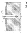
- FIG. 52 is a cross-sectional view of the abdominal surgical site with the flexible screen installed in the abdominal cavity in the intraperitoneal position.
- the reference numeral 2 generally designates a medical closure screen device or system embodying the present invention.
- the primary application disclosed herein is for assistance with the closing, draining, irrigating and healing of a separation of first and second tissue portions, such as a wound or incision 4 .
- the wound 4 extends from and is open at the dermis 6 , through the deep dermal layer 7 and the subcutaneous layer 8 , and to approximately the fascia 10 .
- the wound 4 displays edges 12 a,b , which correspond to first and second tissue portions.
- the closure screen device 2 generally comprises a screen 14 , a screen perimeter member 16 and an input/output (I/O) subsystem 18 .
- the screen 14 includes upper and lower margins 20 a,b ; first and second ends 22 a,b ; and first and second faces 24 a,b .
- the screen 14 generally forms a grid configuration with vertical, hollow, perforated tubular risers 26 cross-connected by horizontal spacer members 28 .
- Multiple barbed strands 30 are positioned between the risers 26 .
- the risers 26 , the spacers 28 and the strands 30 are preferably joined at their respective intersections.
- each strand 30 includes a filament 32 with multiple, pointed barbs 34 extending upwardly and outwardly on both sides in staggered, spaced relation.
- the barbs 34 generally project outwardly from the screen faces 24 a,b , for purposes which will be described in more detail hereinafter.
- the screen or mesh 14 material can be either dissolvable (absorbable) or non-dissolvable (non-absorbable) and can be chosen from a number of commercially-available, biocompatible products, which are commonly used in medical applications for sutures, implantable meshes, and similar medical devices.
- absorbable materials include, but are not limited to: aliphatic polyesters, which include, but are not limited to: homo polymers and copolymers of lactide, .epsilon.-caprolactone, p-dioxanone, trimethylene carbonate, alkyl derivatives of trimethylene carbonate, .delta.-hydroxyvalerate, 1,4-dioxepan-2-one, 1,5-dioxepan-2-one, 6,6-dimethyl-1,4-dioxan-2-one and polymer blends thereof.
- nonabsorbable materials include, but are not limited to: cotton, linen, silk, polyamides, polyesters, fluoropolymers, polyolefins, polyethylene, metals and combinations thereof.
- the optional screen perimeter member 16 can comprise, for example, a flexible, perforated, hollow tube 35 with multiple orifices 36 .
- the tube 35 includes first and second legs 38 , 40 extending generally along the screen first and second ends 22 a,b , and a base leg 41 extending generally along the screen lower margin 20 b .
- the tubing first and second legs 38 , 40 terminate in respective first and second ends 38 a , 40 a .
- the tube 35 can be secured to the screen 14 by multiple ties 42 , which can comprise extensions of the horizontal spacer members 28 and the strands 30 .
- the tube 35 can be designed for separation from the remainder of the closure screen 2 after a relatively short period of time.
- the dissolvable material can dissolve into the patient's body after a few days, whereafter the tube 35 can be removed.
- portions of the tube 35 can be cut away from the screen 14 .
- the screen 14 can be separated along each screen end 22 a,b , or it can be separated completely from the tube 35 .
- the screen 14 and the tube 35 can be configured to accommodate a variety of conditions and tissue separation configurations.
- the vertical risers 26 are optionally fluidically coupled to the tube 35 at respective T intersections 44 .
- the tube 35 and the vertical risers 26 cooperate to provide a manifold for fluid handling, i.e. either extraction or irrigation, as indicated by the fluid flow arrows 45 .
- the input/output subsystem 18 is designed for extraction and/or irrigation of the patient's bodily fluids and/or external fluids. As shown in FIG. 1 , the input/output subsystem 18 includes first and second I/O devices 18 a,b attached to the tubing first and second leg ends 38 a,b , which in this configuration are considered the “port” ends of the tube 35 .
- One or both of the I/O devices 18 a,b can comprise a pressure differential source, such as the NPWT device, The V.A.C.® SystemTM, available from Kinetic Concepts, Inc. of San Antonio, Tex.
- the use of such units for wound treatment and fluid management is disclosed in the Zamierowski U.S. Pat. No. 4,969,880; U.S. Pat. No. 5,100,396; U.S. Pat. No. 5,261,893; U.S. Pat. No. 5,527,293; and U.S. Pat. No. 6,071,267, which are incorporated here
- tubing port ends 38 a,b can be connected to various other sources of pressure differential and various drainage and irrigation devices. For example, they can be cut short below the dermis 6 and left within the separation 4 for sealing by the adjacent tissue portions 12 a,b .
- FIG. 4 a shows a truncated tubing end 38 b .
- the tubing ends 38 a / 40 a can be knotted (as shown at 48 in FIG. 4 b ), clipped, tied (e.g., with a suture) or otherwise closed off either above or below the dermis 6 .
- FIG. 4 c shows a Leur lock coupling 46 mounted on a tubing end 38 a / 40 a .
- a transfer element comprising a piece of foam or sponge 50 can be coupled to the tube 35 at an end 38 a / 40 a ( FIG. 4 d ).
- a pressure differential source such as a vacuum source 51
- a clamp 62 is shown in FIG. 4 f and closes the tube end 38 a / 40 a .
- the clamp 62 can be chosen from among several suitable clamps, which are commonly used for medical applications.
- Either tube end 38 a / 40 a can function as either an inlet port or an outlet port with respect to the system 2 .
- suction can be applied for pulling fluid from the patient through the system 2 through either tube end 38 a / 40 a .
- fluid can be pulled in both directions through the system 2 by alternately or jointly applying suction to the tube ends 38 a / 40 a .
- suction can be simultaneously applied to both tube ends 38 a / 40 a.
- FIGS. 5 a - e show an installation methodology utilizing the system 2 of the present invention.
- the closure screen 2 is placed in the separation 4 with the tubing base 41 located at the bottom of the separation (e.g., wound or incision) 4 and in proximity to the fascia layer 10 .
- the tissue portions or wound/incision edges 12 a,b are spaced apart.
- the screen upper margin 20 a can protrude outwardly from the dermis 6 .
- FIG. 5 b shows the tissue separation edges 12 being pushed together as indicated by the force arrows 52 .
- FIG. 5 c shows the separation edges 12 engaged at the dermis 6 , and spaced apart somewhat within the subcutaneous layer 8 .
- edges 12 can be pushed together as indicated by the force arrows 52 .
- the screen 2 can be held or positioned inwardly in order to advance the barbs 34 in the separation edges 12 , as indicated by the inward or downward force arrows 54 a .
- FIG. 5 d shows the separation edges 12 a,b substantially closed on the screen 2 . Tugging on the screen 14 in the general direction of the outward force arrow 54 b sets the mesh barbs 34 .
- FIG. 5 e shows the separation 4 closed on the closure screen 2 , with the tubing 35 removed from the screen 14 .
- the tubing 35 can be removed either pre-installation by cutting the ties 42 , or post-installation by allowing the ties 42 to dissolve, whereafter the unsecured tubing 35 can be extracted.
- FIG. 6 a shows the barbs 34 compressed by engagement with the separation edges 12 a,b .
- the separation edges 12 can be manually closed by pressing along the horizontal force arrows 52 .
- the barbs 34 allow the separation edges 12 a,b to slide upwardly or outwardly along the screen 14 . This process can be repeated until the separation 4 is closed, as shown in FIG. 6 b . Any protruding length of the screen 14 can be cut close to the dermis 6 .
- the barbs 34 are embedded in the tissue adjacent to the separation edges 12 a,b and thus secure the separation 4 in a closed position.
- the fluid conducting properties of the screen 14 facilitate extracting fluid.
- An outward or upward force arrow 54 b indicates a force direction whereby the screen barbs 34 are set in the adjoining tissue. It will be appreciated that the screen 14 can be securely set in place with the barbs 34 , yet the separation edges 12 a,b will remain capable of sliding up on the screen 14 by disengaging the barbs 34 with lateral forces, as shown in FIG. 6 a .
- Skin hooks 55 can be used for engaging the tissue portions 12 a,b and tugging same outwardly as shown in FIG. 6 a . The skin hooks 55 can facilitate positioning and repositioning the screen 14 .
- FIGS. 7 a - f show an alternative procedure for mounting the closure screen 2 in a wound drainage application utilizing pressure differential.
- the tubing 35 can pass through the tissue adjacent to the wound 4 and exit the dermis 6 for termination of the tubing end 38 a / 40 a as described above.
- An optional layer of a suitable, biocompatible adhesive 64 is shown applied to the closure screen first face 24 a for securing same to the first wound edge 12 a .
- FIG. 7 b shows the screen 14 extending upwardly from the dermis 6 with the wound edges 12 a,b brought together in a manner similar to that described above.
- the input/output subsystem 18 includes a pair of optional fluid transfer elements comprising foam or sponge members 56 a,b placed on the dermis 6 on either side of a protruding portion 14 a of the screen 14 .
- the screen 14 is then cut to a level generally flush with the upper surfaces of the sponges 56 a,b , as shown in FIG. 7 c .
- An optional sponge bridge 58 is placed over the sponge members 56 a,b ( FIG. 7 d ).
- suitable transfer element materials are discussed in the Zamierowski patents noted above and include open-cell, porous foam materials (e. g., polyurethane ester (PUE)) chosen for their hydrophobic properties and passage of liquids.
- PUE polyurethane ester
- Polyvinyl acetate (PVA) material can be used for its hydrophilic properties.
- the transfer element subassembly 59 formed by the sponge members 56 a,b and 58 can be connected to a vacuum source, a fluid irrigation source, etc. Moreover, it can be connected to additional fluid transfer elements and covered with various flexible membranes and drapes, which can be semi-permeable or impervious, as indicated for the closure and treatment of particular separations and wounds.
- FIG. 7 e shows a tubing placement tool 120 with a handle 122 , a shaft 124 and a hook 126 terminating at a pointed or rounded, bullet-shaped tip 128 .
- FIG. 7 f shows the tool 120 passing tubing 35 through tissue in the subcutaneous layer 8 and into proximity with the dermis 6 .
- the tip 128 is received in a blind end 134 of the tubing 35 through a notch 136 formed therein.
- the thrust of the tool 120 causes tenting of the dermis 6 , as shown at 138 , whereat the dermis 6 can be opened with a scalpel 140 and the tubing 35 can exit the patient for suitable termination arrangements, such as those shown in FIGS. 4 a - f above.
- FIG. 8 shows a modified embodiment closure system 202 with a pair of screens 14 positioned generally end-to-end in a separation 204 .
- a transfer element subassembly 59 is placed over the separation 204 and a membrane drape 205 is placed thereover.
- the tube 35 is passed through tissue on either side of the separation 204 (e.g., using the procedure and the tubing placement tool 120 described above) and exits the dermis 6 on either side of the transfer element subassembly 59 .
- the tube 35 lengths are knotted at 206 .
- the tube 35 lengths thus function as sutures or retainers for securing the closure system 202 in the separation 204 .
- the tube ends 38 a or 40 a can be utilized for this purpose, thus leaving the other tubing ends available for fluid communication with one or more of the input/output subsystems 18 described above.
- the tube 35 can be secured by suitable fasteners, such as clips and the like, located above the dermis 6 .
- the screens 14 can be overlapped, abutted, spaced slightly and otherwise configured and positioned as necessary for particular tissue separations. Still further, the screens 14 are adapted to be trimmed as necessary.
- FIG. 9 shows a modified embodiment tubing/suture subassembly 220 with a Trocar instrument 222 including a sharpened, distal end 224 and a proximate end 226 with multiple, annular ridges 226 a .
- a length of flexible tubing 228 combines the functions of screen perimeter member and suture.
- the flexible tubing 228 terminates at an end 228 a adapted for releasably mounting on the needle proximate end 226 , whereat it is retained in place by the ridges 226 a .
- the tubing 228 is optionally connected to the screen 14 as described above and can include perforations 228 b for fluid drainage and/or irrigation in conjunction with input/output subsystems 18 , also as described above.
- the tubing/suture subassembly 220 is adapted for securing the screen 14 in place and for closing the separation 4 by passing the tubing 228 through adjacent tissue.
- the tubing/suture subassembly 220 and the screen 14 can be prepackaged and presterilized for closing and treating separations, which can include wounds and incisions.
- FIGS. 10 , 11 a and 11 b show modified embodiment closure screen systems 302 with first and second suture subassemblies 304 , 306 comprising the screen perimeter member.
- the suture subassemblies 304 , 306 include respective curved needles 304 a , 306 a which are swaged or adhesively connected to opposite ends 304 b , 306 b of a common length of suture thread 307 .
- the suture thread 307 can be absorbable or nonabsorbable.
- the screen closure system 302 can be preassembled with the suture thread length 307 releasably secured to the perimeter 308 a of a screen 308 .
- the suture 307 Prior to installation of the screen 308 , the suture 307 can be disconnected or severed therefrom, either partly or completely. For example, the suture 307 can be separated along the screen ends 310 a , 310 b respectively, thereby leaving the suture thread lengths secured only along a screen lower margin 312 .
- the suture subassemblies 304 , 306 facilitate installation of the suture/screen closure system 302 , thereby providing a preassembled device which incorporates the necessary components for securing same in a separation 4 .
- the screen 308 can be secured at the bottom alone by passing the suture subassemblies 304 , 306 through tissue portions located at the bottom of the separation 4 .
- the suture subassemblies 304 , 306 can be passed through the adjacent tissue and exit the surface of the dermis 6 , whereby the suture subassemblies 304 , 306 can be used for closing the separation 4 at the dermis 6 .
- Barbed strands 320 can interact with the tissue portions 12 a,b as described above, whereby the screen 308 provides a relatively secure mechanical connection between the separated tissue portions 12 a,b .
- the suture subassemblies 304 , 306 can be utilized for various purposes in the separation 4 , including attachment and tacking of the dermis 6 , the deep dermal layer 7 , the subcutaneous layer 8 and the fascia 10 . Still further, all or part of the suture subassemblies 304 , 306 can be removed, and additional suture subassemblies can be mounted on or sutured to the screen 308 .
- FIG. 11 a shows the screen 308 attached to the suture thread 307 .
- FIG. 11 b shows an alternative construction screen 318 with hollow tubular vertical risers 324 located between adjacent, respective vertical strands 320 , all connected by the spacers 322 and adapted for communicating fluid with the separation 4 through the open riser ends 324 a and the perforations 324 b , as indicated by the fluid flow arrows 326 .
- All or part of the screen/suture system 302 can comprise absorbable material.
- FIGS. 12 , 13 a and 13 b show a modified embodiment screen-only closure screen system 402 and application methodology.
- a screen or mesh 404 similar to the screen 14 with barbed strands 30 described above, is placed in a separation 4 against the first tissue portion 12 a .
- the second tissue portion 12 b is then placed against the screen 404 whereby the separation 4 is closed and can be secured by the mechanical action of the screen 404 .
- the screen 404 can be supplemented with sutures, drainage tubing, I/O devices, and other auxiliary components for purposes of closing the wound edges 12 , draining the inside of the tissue separation 4 , fighting infection, pain management and all other functionalities associated with the present invention, as discussed elsewhere herein.
- the screen 404 can be secured with sutures at the subcutaneous level 8 .
- Various fluid interconnecting devices can be utilized as necessary, and can be designed for removal after they serve their initial purpose.
- External drainage can also be achieved at the dermis level 6 utilizing transfer element subassemblies, such as the example designated 59 and described above ( FIG. 7 d ).
- drainage and irrigation tubing can be installed within the wound 4 alongside or adjacent to the screen 404 .
- a screen-only version of the invention can comprise various suitable biocompatible absorbable and non-absorbable materials, including the materials disclosed above.
- FIG. 13 a is an enlarged view of the screen 404 and particularly shows barbed strands 406 and horizontal spacers 408 , which are connected together in a grid pattern forming the screen 404 .
- FIG. 13 b shows an alternative embodiment with a modified screen 410 including vertical risers 412 comprising hollow tubing, which are connected to and spaced by horizontal spacers 408 . Fluid flows into and out of the vertical risers 412 through open riser ends 412 a and perforations 412 b , as indicated by the fluid flow arrows 420 .
- FIGS. 14 a - g show the screen 404 installed in a tissue separation 4 and closing same, utilizing the methodology of the present invention.
- the methodology shown in FIGS. 14 a - g is similar to the methodology shown in FIGS. 5 a - e and 6 a,b .
- FIG. 14 c shows a downward/inward force arrow 54 a indicating a direction in which the screen 404 is pushed or guided into the separation.
- FIGS. 15 a,b and 16 a,b show a modified vertical riser 502 comprising bundled tubes 504 secured together at spaced intervals by connectors 506 .
- the normal movement of the patient tends to alternately compress and expand the vertical risers 502 , thus providing a “pumping” action for transferring fluid from the wound 4 , as indicated by the fluid flow arrows 510 .
- FIGS. 15 a,b show a riser 502 in an extended configuration. Compressing the screen 14 longitudinally (i.e., end-to-end) compresses the bundled risers 504 to the configuration shown in FIGS. 16 a,b , whereby fluid is drawn into the interstitial space 508 and pumped therefrom when the risers 502 extend.
- FIG. 17 shows yet another configuration of a vertical riser 602 with bundled tubes 604 , which are closely bunched and define passages 606 for conveying fluid. Such fluid conveyance can be enhanced by a pumping action associated with normal patient movements. Barbs 608 project outwardly from the tubes 604 . It will be appreciated that various other bundled tube configurations, such as twisted, braided, etc., can be utilized.
- FIG. 18 shows yet another vertical riser/perimeter member 702 alternative embodiment configuration.
- the member 702 has a configuration which is commonly referred to as a “fluted” drain and includes longitudinally-extending passages 704 .
- This configuration can substitute for the perimeter members described above and can function to communicate fluid to and from the wound 4 with the input/output subsystem 18 .
- the vertical risers can comprise either barbed monofilament strands, similar to strand 30 shown in FIG. 3 , or unbarbed monofilament strands.
- Such monofilament vertical risers can function as passive drains with fluid flowing alongside same. They can extend above the dermis 6 and abut or connect to transfer elements formed in various configurations with suitable absorbent materials. Examples include gauze dressings and transfer element subassemblies, such as 59 shown in FIG. 7 d.
- FIG. 19 shows an alternative embodiment strand 802 constructed by twisting and braiding multiple, individual filaments 804 .
- Barbs 805 are formed by respective individual filaments 804 a , which terminate at blunt ends 806 .
- the barbs 805 project generally outwardly from the strand 802 and form acute angles with respect to its longitudinal axis. They are adapted for penetrating tissue within a separation 4 , as described above. In use, the barbs 805 would normally be oriented in directions generally pointing outwardly from the patient and the tissue separation 4 .
- FIG. 20 shows another alternative embodiment strand 902 comprising multiple twisted and braided filaments 904 .
- Barbs 905 are formed from individual filaments 904 a and have notches 908 and pointed ends 910 .
- the notches 908 and the ends 910 are configured to allow the barbs 905 to easily extract from the separation edge tissues, whereby the screen is adapted for sliding along the separation edges in order to achieve the proper position.
- FIG. 21 shows a further modified screen 1002 with barbs 1004 formed by looping individual filaments 1006 and cutting same at cut locations 1010 spaced inwardly from respective apexes 1008 of the filament loops.
- the barbs 1004 slightly penetrate the tissue and are imbedded therein.
- the filaments 1006 are relatively thin in diameter, similar to microfibers, whereby patient comfort is optimized.
- FIG. 22 shows yet another modified screen 1102 with barbs 1104 formed by looping individual filaments 1106 and cutting same at locations 1110 spaced inwardly from respective apexes 1108 of the filament loops whereby respective hooks 1112 are formed.
- the hooks 1112 operate in a manner similar to hook-and-loop fasteners, with the adjacent tissue forming the loop parts of the connections. In operation, the hooks 1112 slightly penetrate the tissue and are imbedded therein. The configurations of the hooks 1112 tend to retain them in the tissue adjacent to the separation 4 whereby the separated first and second tissue portions 12 a,b can be closed.
- FIG. 23 shows a screen 1202 with a configuration similar to the screen 1002 discussed above, with additional fiber elements or filaments 1204 .
- the additional filaments 1204 tend to lay the filament barbs 1206 over whereby the screen 1202 can be directionally oriented within the wound separation 4 and operate in a manner similar to the screen 14 described above.
- the barbs 1206 are formed by cutting the apexes 1208 at cut locations 1210 .
- FIG. 24 shows a screen 1302 with additional filaments 1304 , which engage the filament loops 1306 and orient same in a direction towards the right as shown in FIG. 24 .
- the slanted orientations of the filament loops 1306 facilitate setting same in the tissue portions 12 a,b adjacent to the separation 4 by tugging outwardly on the screen 1302 .
- Repositioning the screen 1302 is also possible, as described above.
- the filament loops 1306 can be cut at cut locations 1310 , which are spaced inwardly from filament loop apexes 1308 whereby hooks 1312 are formed.
- FIGS. 21-24 disclose screens with barbs and hooks extending from one face thereof.
- the present invention also includes screens with barbs and hooks extending from both faces.
- FIGS. 25-30 A closure screen comprising a further modified aspect or embodiment of the invention is shown in FIGS. 25-30 and is generally designated by the reference numeral 1402 .
- the screen 1402 generally comprises a highly flexible panel 1404 , which engages and approximates adjacent tissue portions across a separation by the semi-independent action of multiple, individual links 1406 , which are strung together in respective strands 1408 .
- the screen 1402 includes a pre-installation enclosure assembly 1424 comprising front and back backing sheets 1426 , 1428 , which can be provided with a suitable releasable adhesive 1429 .
- the backing sheets 1426 , 1428 preferably comprise paper or other material (e.g., Styrofoam® material), which is relatively stiff (as compared to the relatively flimsy panel 1404 ) for maintaining the flat shape of the closure screen 1402 during handling and placement in the patient and for protection from the sharpened prong tips.
- An outer edge handling strip 1430 is mounted on the upper edge of perimeter 1432 of the panel 1404 ( FIG. 25 ) and is adapted for grasping manually or with instruments in order to facilitate handling, alignment and placement.
- FIG. 26 shows a closure screen 1402 being placed in a tissue separation 4 with a suitable instrument, such as forceps 1434 .
- FIG. 27 shows the panels 1404 of two closure screens 1402 in place with the backing pieces 1426 and 1428 removed and with the separated tissue portions 12 a,b pushed together and approximated by the panels 1404 .
- Selvage edges 1436 can be trimmed flush with the skin surface and removed along with the handling strips 1430 .
- the closed separation 4 can be covered with a suitable cover strip 1438 , which can provide tensile retaining strength for securing the tissue portions 12 a,b together, as well as protecting the separation 4 during healing ( FIG. 28 ).
- FIG. 29 shows a closure screen 1502 in place in a tissue separation 4 .
- FIG. 30 shows extracting a back backing sheet 1508 , whereby the panel 1504 is placed against the tissue portion 12 b for engaging same by penetrating its prongs into the tissue approximately 1-2 mm or whatever length is dictated by particular tissue requirements.
- FIGS. 31-46 show the construction and operation of another modified embodiment or aspect of a closure screen 1502 embodying the present invention.
- FIG. 31 shows the closure screen 1502 assembled, with front and back backing sheets 1506 , 1508 enclosing a tissue approximation panel 1504 .
- FIG. 32 is an exploded view thereof, with the tissue approximation panel 1504 adapted for placement between the front and back backing sheets 1506 , 1508 .
- the backing sheets 1506 , 1508 have upper margins 1510 , 1512 respectively, with the back backing sheet upper margin 1512 extending higher than the front backing sheet upper margin 1510 , which facilitates gripping the back sheet 1508 at its upper margin 1512 with forceps or some other similar instrument.
- FIGS. 33 and 34 show another embodiment closure screen 1513 with a square closure panel 1514 with a similar construction to the rectangular panel 1504 .
- FIG. 35 shows the tissue separation 4 with first and second separated tissue portions or edges 12 a,b .
- FIG. 36 shows the placement of a closure screen 1513 with dashed lines indicating panels 1514 , which are already in place in the tissue separation 4 .
- a tissue separation 4 can be “tiled” with the closure panels 1514 , which can be of any suitable size and number depending upon the configuration of the separation 4 .
- FIG. 37 shows the screen 1502 ( FIG. 31 ) in place with its back backing sheet 1508 removed, whereby the prongs are exposed to and penetrate the tissue portion 12 b .
- the opposite tissue portion 12 a can be pushed in the direction of directional arrow 1516 to approximate closure.
- FIG. 38 shows the lower (innermost) portion of the tissue separation 4 approximated, with the front backing sheet 1506 being removed in FIG. 39 , resulting in the condition shown in FIG. 40 with the lower portion of the tissue separation 4 secured or “approximated” against the closure panel 1504 .
- FIGS. 41-46 show securing an upper (or outer/distal) portion of the tissue separation 4 with another closure screen 1502 by essentially repeating the procedure described above.
- a protruding distal selvage margin 1518 is removed from the outermost panel 1504 as shown in FIG. 44 substantially flush with the skin surface.
- a suitable cover 1520 is placed over the tissue separation as shown in FIG. 45 .
- the prongs of the various embodiment closure screens and clips can have various suitable sizes and configurations, including curved, straight, barbed, etc. Closure and approximation of the tissue separation 4 can be augmented with tape, adhesive, staples, sutures or other closure devices, including a pressure differential source, such as the NPWT device, The V.A.C.® SystemTM, available from Kinetic Concepts, Inc. of San Antonio, Tex., which can be chosen to promote wound closure in conjunction with a closure screen or screens.
- a pressure differential source such as the NPWT device, The V.A.C.® SystemTM, available from Kinetic Concepts, Inc. of San Antonio, Tex.
- FIG. 47 shows another alternative embodiment closure screen 2302 with a backing sheet 2304 having a lower removable strip 2306 , which exposes a lowermost row 2308 of clips for initially positioning the screen 2302 , whereafter an upper portion 2310 of the backing sheet 2304 can be removed.
- FIGS. 48 a - c show another embodiment closure screen 2352 with a row of closure clips 2354 , which can be mounted along a bottom edge 2356 of a panel 2358 of the closure screen 2352 .
- Each closure clip 2354 includes first and second rows of laterally-projecting hooks 2360 a,b , which are adapted and positioned for penetrating respective tissue portions 12 a,b .
- a sequential procedure for closing a lower or inner portion of a tissue separation 4 can begin with the closure clips 2354 positioned within the tissue separation 4 as shown in FIG. 48 a .
- the first row of hooks 2360 a can be embedded in the first tissue portion 12 a , for example by tilting and manipulating the panel 2358 ( FIG. 48 b ).
- Closure can be accomplished by embedding the second row of hooks 2360 b in the second separated tissue portion 12 b ( FIG. 48 c ), for example, by tilting and manipulating the panel 2358 .
- the closure screen 2352 with the closure clips 2354 can be used in conjunction with the enclosure assembly of the closure screen 2302 , whereby the lower row of links 2308 can be exposed for supplementing the closure clips 2354 in connection with initially anchoring the closure screen.
- the clips 2354 can be provided in any suitable number and spacing, including a clip 2354 at the lower end of each column of links, at the lower end of every other column of links, etc.
- FIG. 49 shows an additional alternative embodiment closure screen 2402 , which is constructed by mounting discrete clips 2404 on a backing 2406 , which can retain the clips 2404 by a suitable adhesive or some other means pre-installation.
- FIG. 50 shows yet another alternative embodiment closure screen 2502 , which is similar to the screen 2402 but with fewer and different clips 2504 .
- the clips 2504 have prongs 2506 , which are curved in an outwardly-convex direction with respect to bodies 2508 of the clips 2504 .
- the curvature of the prongs 2506 can facilitate penetration and closure of the separated tissue portions 12 a,b .
- the prongs 2506 can also be straight, barbed, etc., and can be oriented at any suitable angle with respect to the bodies 2508 of the clips 2504 .
- FIGS. 51 and 52 show a closure screen 1902 applied to an abdominal incision 1904 .
- Such incisions are typically involved in abdominal surgery procedures and can result in various complications, including infection and difficulties in closure and healing.
- the abdominal tissues are exposed within the abdominal cavity to a perimeter 1906 .
- the screen 1902 can be provided with multiple rigid or semi-rigid non-collapsible members 1908 for maintaining its general shape and facilitating its placement in the abdominal cavity, preferably to approximately the perimeter 1906 .
- the screen 1902 includes a panel with opposite faces and multiple prongs projecting from said faces.
- the prongs 1910 can be oppositely-oriented towards a medial line or centerline 1916 for directing the opposite sidcs of the incision 1904 towards medial closure.
- the medial line or centerline 1916 divides the panel into first and second portions.
- the screen 1902 can be provided with a perimeter member 1912 . which is preferably sized and configured to place and maintain the screen in proximity to the tissue separation perimeter 1906 . Relatively extensive coverage of the abdominal tissue separation can thus be achieved, particularly with the positioning effects of the non-collapsible members 1908 and the perimeter member 1912 in combination.
- a pre-installation enclosure assembly including front and back backing sheets can be mounted on opposite sides of the screen 1902 pre-installation, for removal to expose the prongs 1910 for engaging the tissue portions.
- the screen 1902 can be positioned between abdominal tissue layers with the medial line or centerline 1916 located below the abdominal incision.
- this device can also be placed in pre-peritoneal positions and on the musculature, in addition to placement intra-abdominally between the musculature and an inner tissue layer 1914 , as shown in FIG. 52 .
Abstract
Description
Claims (8)
Priority Applications (4)
| Application Number | Priority Date | Filing Date | Title |
|---|---|---|---|
| US11/103,022 US7413570B2 (en) | 2002-08-21 | 2005-04-11 | Medical closure screen installation systems and methods |
| US12/130,516 US8123781B2 (en) | 2002-08-21 | 2008-05-30 | Screen devices and methods for closing tissue separations |
| US12/130,682 US8070773B2 (en) | 2002-08-21 | 2008-05-30 | Medical closure methods and screen devices |
| US12/190,521 US8062331B2 (en) | 2002-08-21 | 2008-08-12 | Internal and external medical closure screen systems and methods |
Applications Claiming Priority (2)
| Application Number | Priority Date | Filing Date | Title |
|---|---|---|---|
| US10/224,852 US7381211B2 (en) | 2002-08-21 | 2002-08-21 | Medical closure screen device and method |
| US11/103,022 US7413570B2 (en) | 2002-08-21 | 2005-04-11 | Medical closure screen installation systems and methods |
Related Parent Applications (1)
| Application Number | Title | Priority Date | Filing Date |
|---|---|---|---|
| US10/224,852 Continuation-In-Part US7381211B2 (en) | 2002-08-21 | 2002-08-21 | Medical closure screen device and method |
Related Child Applications (2)
| Application Number | Title | Priority Date | Filing Date |
|---|---|---|---|
| US11/103,403 Continuation-In-Part US20060171335A1 (en) | 2002-08-21 | 2005-04-11 | Backup channel selection in wireless LANs |
| US12/190,521 Continuation-In-Part US8062331B2 (en) | 2002-08-21 | 2008-08-12 | Internal and external medical closure screen systems and methods |
Publications (2)
| Publication Number | Publication Date |
|---|---|
| US20050177190A1 US20050177190A1 (en) | 2005-08-11 |
| US7413570B2 true US7413570B2 (en) | 2008-08-19 |
Family
ID=46304329
Family Applications (1)
| Application Number | Title | Priority Date | Filing Date |
|---|---|---|---|
| US11/103,022 Expired - Lifetime US7413570B2 (en) | 2002-08-21 | 2005-04-11 | Medical closure screen installation systems and methods |
Country Status (1)
| Country | Link |
|---|---|
| US (1) | US7413570B2 (en) |
Cited By (56)
| Publication number | Priority date | Publication date | Assignee | Title |
|---|---|---|---|---|
| US20070293946A1 (en) * | 2006-05-12 | 2007-12-20 | Entrigue Surgical, Inc. | Middle Turbinate Medializer |
| US20090224064A1 (en) * | 2008-03-10 | 2009-09-10 | Vapore, Inc. | Low Energy Vaporization of Liquids: Apparatus and Methods |
| US20090264807A1 (en) * | 2005-09-07 | 2009-10-22 | Tyco Healthcare Group Lp | Self contained wound dressing with micropump |
| US20100179493A1 (en) * | 2009-01-09 | 2010-07-15 | Tyco Healthcare Group Lp | Canister for Receiving Wound Exudate in a Negative Pressure Therapy System |
| US20100305523A1 (en) * | 2009-05-27 | 2010-12-02 | Tyco Healthcare Group Lp | Active Exudate Control System |
| US20110004173A1 (en) * | 2007-10-11 | 2011-01-06 | Dean Hu | Closed Incision Negative Pressure Wound Therapy Device and Methods of Use |
| US8007481B2 (en) | 2008-07-17 | 2011-08-30 | Tyco Healthcare Group Lp | Subatmospheric pressure mechanism for wound therapy system |
| US8021347B2 (en) | 2008-07-21 | 2011-09-20 | Tyco Healthcare Group Lp | Thin film wound dressing |
| US8048046B2 (en) | 2008-05-21 | 2011-11-01 | Tyco Healthcare Group Lp | Wound therapy system with housing and canister support |
| US8152785B2 (en) | 2008-03-13 | 2012-04-10 | Tyco Healthcare Group Lp | Vacuum port for vacuum wound therapy |
| US8162907B2 (en) | 2009-01-20 | 2012-04-24 | Tyco Healthcare Group Lp | Method and apparatus for bridging from a dressing in negative pressure wound therapy |
| US8167869B2 (en) | 2009-02-10 | 2012-05-01 | Tyco Healthcare Group Lp | Wound therapy system with proportional valve mechanism |
| US8177763B2 (en) | 2008-09-05 | 2012-05-15 | Tyco Healthcare Group Lp | Canister membrane for wound therapy system |
| US8246592B2 (en) | 2000-11-29 | 2012-08-21 | Kci Medical Resources | Vacuum therapy and cleansing dressing for wounds |
| US8246591B2 (en) | 2009-01-23 | 2012-08-21 | Tyco Healthcare Group Lp | Flanged connector for wound therapy |
| US8251979B2 (en) | 2009-05-11 | 2012-08-28 | Tyco Healthcare Group Lp | Orientation independent canister for a negative pressure wound therapy device |
| US8257326B2 (en) | 2008-06-30 | 2012-09-04 | Tyco Healthcare Group Lp | Apparatus for enhancing wound healing |
| US8257328B2 (en) | 2008-07-08 | 2012-09-04 | Tyco Healthcare Group Lp | Portable negative pressure wound therapy device |
| US8298200B2 (en) | 2009-06-01 | 2012-10-30 | Tyco Healthcare Group Lp | System for providing continual drainage in negative pressure wound therapy |
| US8366693B2 (en) | 2009-04-10 | 2013-02-05 | Spiracur, Inc. | Methods and devices for applying closed incision negative pressure wound therapy |
| US8398604B2 (en) | 2009-04-10 | 2013-03-19 | Spiracur, Inc. | Methods and devices for applying closed incision negative pressure wound therapy |
| US8540687B2 (en) | 1998-08-07 | 2013-09-24 | Kci Licensing, Inc. | Wound treatment apparatus |
| US8569566B2 (en) | 2003-10-28 | 2013-10-29 | Smith & Nephew, Plc | Wound cleansing apparatus in-situ |
| US8585721B2 (en) | 2011-10-12 | 2013-11-19 | Covidien Lp | Mesh fixation system |
| US8628505B2 (en) | 2002-09-03 | 2014-01-14 | Bluesky Medical Group Incorporated | Reduced pressure treatment system |
| US8747887B2 (en) | 2000-05-22 | 2014-06-10 | Kci Medical Resources | Combination SIS and vacuum bandage and method |
| US8777911B2 (en) | 2008-08-08 | 2014-07-15 | Smith & Nephew, Inc. | Wound dressing of continuous fibers |
| US8784439B1 (en) * | 2006-11-28 | 2014-07-22 | Stephen V. Ward | Percutaneous medical procedures and devices for closing vessels using mechanical closures |
| US8827983B2 (en) | 2008-08-21 | 2014-09-09 | Smith & Nephew, Inc. | Sensor with electrical contact protection for use in fluid collection canister and negative pressure wound therapy systems including same |
| US8979875B2 (en) | 2008-09-17 | 2015-03-17 | Arthrocare Corporation | Methods and systems for medializing a turbinate |
| US9155821B2 (en) | 2009-06-10 | 2015-10-13 | Smith & Nephew, Inc. | Fluid collection canister including canister top with filter membrane and negative pressure wound therapy systems including same |
| US20160051255A1 (en) * | 2006-07-01 | 2016-02-25 | Opus Ksd Inc. | Deploying fasteners |
| US9289542B2 (en) | 2003-10-28 | 2016-03-22 | Smith & Nephew Plc | Wound cleansing apparatus |
| US9302034B2 (en) | 2011-04-04 | 2016-04-05 | Smith & Nephew, Inc. | Negative pressure wound therapy dressing |
| US9414968B2 (en) | 2008-09-05 | 2016-08-16 | Smith & Nephew, Inc. | Three-dimensional porous film contact layer with improved wound healing |
| US9545463B2 (en) | 2004-04-28 | 2017-01-17 | Smith & Nephew Plc | Wound treatment apparatus and method |
| US9597484B2 (en) | 2011-04-15 | 2017-03-21 | University Of Massachusetts | Surgical cavity drainage and closure system |
| US9844473B2 (en) | 2002-10-28 | 2017-12-19 | Smith & Nephew Plc | Apparatus for aspirating, irrigating and cleansing wounds |
| US9950100B2 (en) | 2004-04-28 | 2018-04-24 | Smith & Nephew Plc | Negative pressure wound therapy dressing system |
| US10010658B2 (en) | 2013-05-10 | 2018-07-03 | Smith & Nephew Plc | Fluidic connector for irrigation and aspiration of wounds |
| US10045777B2 (en) | 2013-01-31 | 2018-08-14 | Opus Ksd Inc. | Delivering bioabsorbable fasteners |
| US10245185B2 (en) | 2011-06-07 | 2019-04-02 | Smith & Nephew Plc | Wound contacting members and methods |
| US10342729B2 (en) | 2004-04-27 | 2019-07-09 | Smith & Nephew Plc | Wound cleansing apparatus with stress |
| US10357404B2 (en) | 2000-11-29 | 2019-07-23 | Kci Medical Resources Unlimited Company | Vacuum therapy and cleansing dressing for wounds |
| US10406036B2 (en) | 2009-06-18 | 2019-09-10 | Smith & Nephew, Inc. | Apparatus for vacuum bridging and/or exudate collection |
| US10413644B2 (en) | 2004-04-27 | 2019-09-17 | Smith & Nephew Plc | Wound treatment apparatus and method |
| US10441270B2 (en) | 2008-11-03 | 2019-10-15 | Ethicon, Inc. | Length of self-retaining suture and method and device for using the same |
| CN110598323A (en) * | 2019-09-12 | 2019-12-20 | 中国水利水电科学研究院 | Simulation method for osmotic damage discrete element |
| US10709537B2 (en) * | 2009-05-07 | 2020-07-14 | Covidien Lp | Surgical patch cover and method of use |
| US10744239B2 (en) | 2014-07-31 | 2020-08-18 | Smith & Nephew, Inc. | Leak detection in negative pressure wound therapy system |
| US10779815B2 (en) | 2004-05-14 | 2020-09-22 | Ethicon, Inc. | Suture methods and devices |
| US10912869B2 (en) | 2008-05-21 | 2021-02-09 | Smith & Nephew, Inc. | Wound therapy system with related methods therefor |
| US10952721B2 (en) | 2010-05-04 | 2021-03-23 | Ethicon, Inc. | Laser cutting system and methods for creating self-retaining sutures |
| US11298453B2 (en) | 2003-10-28 | 2022-04-12 | Smith & Nephew Plc | Apparatus and method for wound cleansing with actives |
| US11458004B2 (en) | 2017-10-19 | 2022-10-04 | C.R. Bard, Inc. | Self-gripping hernia prosthesis |
| US11690614B2 (en) | 2011-03-23 | 2023-07-04 | Ethicon, Inc. | Self-retaining variable loop sutures |
Families Citing this family (66)
| Publication number | Priority date | Publication date | Assignee | Title |
|---|---|---|---|---|
| US8795332B2 (en) | 2002-09-30 | 2014-08-05 | Ethicon, Inc. | Barbed sutures |
| US6241747B1 (en) | 1993-05-03 | 2001-06-05 | Quill Medical, Inc. | Barbed Bodily tissue connector |
| US5931855A (en) | 1997-05-21 | 1999-08-03 | Frank Hoffman | Surgical methods using one-way suture |
| US6824533B2 (en) | 2000-11-29 | 2004-11-30 | Hill-Rom Services, Inc. | Wound treatment apparatus |
| US6764462B2 (en) | 2000-11-29 | 2004-07-20 | Hill-Rom Services Inc. | Wound treatment apparatus |
| US7763769B2 (en) | 2001-02-16 | 2010-07-27 | Kci Licensing, Inc. | Biocompatible wound dressing |
| US7700819B2 (en) | 2001-02-16 | 2010-04-20 | Kci Licensing, Inc. | Biocompatible wound dressing |
| US7056331B2 (en) | 2001-06-29 | 2006-06-06 | Quill Medical, Inc. | Suture method |
| US6848152B2 (en) | 2001-08-31 | 2005-02-01 | Quill Medical, Inc. | Method of forming barbs on a suture and apparatus for performing same |
| CA2462877A1 (en) | 2001-10-11 | 2003-04-17 | Hill-Rom Services, Inc. | Waste container for negative pressure therapy |
| WO2003057070A2 (en) | 2001-12-26 | 2003-07-17 | Hill-Rom Services Inc. | Vented vacuum bandage and method |
| CA2468307A1 (en) | 2001-12-26 | 2003-07-17 | Hill-Rom Services, Inc. | Vacuum bandage packing |
| CA2468309A1 (en) | 2001-12-26 | 2003-07-17 | Robert Petrosenko | Wound vacuum therapy dressing kit |
| WO2003086232A2 (en) | 2002-04-10 | 2003-10-23 | Hill-Rom Services, Inc. | Access openings in vacuum bandage |
| US6773450B2 (en) | 2002-08-09 | 2004-08-10 | Quill Medical, Inc. | Suture anchor and method |
| JP2005536275A (en) | 2002-08-21 | 2005-12-02 | ヒル−ロム サービシズ,インコーポレイテッド | Wound packing to prevent wound closure |
| US8100940B2 (en) | 2002-09-30 | 2012-01-24 | Quill Medical, Inc. | Barb configurations for barbed sutures |
| US20040088003A1 (en) | 2002-09-30 | 2004-05-06 | Leung Jeffrey C. | Barbed suture in combination with surgical needle |
| US7624487B2 (en) | 2003-05-13 | 2009-12-01 | Quill Medical, Inc. | Apparatus and method for forming barbs on a suture |
| GB0325130D0 (en) | 2003-10-28 | 2003-12-03 | Smith & Nephew | Apparatus with scaffold |
| US8062272B2 (en) | 2004-05-21 | 2011-11-22 | Bluesky Medical Group Incorporated | Flexible reduced pressure treatment appliance |
| US10058642B2 (en) | 2004-04-05 | 2018-08-28 | Bluesky Medical Group Incorporated | Reduced pressure treatment system |
| US7909805B2 (en) | 2004-04-05 | 2011-03-22 | Bluesky Medical Group Incorporated | Flexible reduced pressure treatment appliance |
| GB0409444D0 (en) | 2004-04-28 | 2004-06-02 | Smith & Nephew | Apparatus |
| GB0508531D0 (en) | 2005-04-27 | 2005-06-01 | Smith & Nephew | Sai with ultrasound |
| GB0524027D0 (en) * | 2005-11-25 | 2006-01-04 | Smith & Nephew | Fibrous dressing |
| CA2643527A1 (en) * | 2006-04-13 | 2007-10-13 | Kci Licensing, Inc. | Medical closure clip system and method |
| AU2006342253B2 (en) * | 2006-04-13 | 2013-01-24 | Solventum Intellectual Properties Company | Medical closure screen installation systems and methods |
| US7931651B2 (en) | 2006-11-17 | 2011-04-26 | Wake Lake University Health Sciences | External fixation assembly and method of use |
| US8377016B2 (en) | 2007-01-10 | 2013-02-19 | Wake Forest University Health Sciences | Apparatus and method for wound treatment employing periodic sub-atmospheric pressure |
| WO2008142580A2 (en) * | 2007-03-16 | 2008-11-27 | Wolfe Tory Medical, Inc. | Temporary surgical closure for a body cavity |
| US8915943B2 (en) | 2007-04-13 | 2014-12-23 | Ethicon, Inc. | Self-retaining systems for surgical procedures |
| GB0712739D0 (en) | 2007-07-02 | 2007-08-08 | Smith & Nephew | Apparatus |
| GB0712764D0 (en) | 2007-07-02 | 2007-08-08 | Smith & Nephew | Carrying Bag |
| US7790946B2 (en) * | 2007-07-06 | 2010-09-07 | Tyco Healthcare Group Lp | Subatmospheric pressure wound therapy dressing |
| WO2009042841A2 (en) | 2007-09-27 | 2009-04-02 | Angiotech Pharmaceuticals, Inc. | Self-retaining sutures including tissue retainers having improved strength |
| WO2009049058A1 (en) | 2007-10-10 | 2009-04-16 | Wake Forest University Health Sciences | Devices and methods for treating spinal cord tissue |
| DE102007058256A1 (en) * | 2007-11-26 | 2009-05-28 | Aesculap Ag | Surgical thread mesh |
| EP2222233B1 (en) | 2007-12-19 | 2020-03-25 | Ethicon, LLC | Self-retaining sutures with heat-contact mediated retainers |
| US8916077B1 (en) | 2007-12-19 | 2014-12-23 | Ethicon, Inc. | Self-retaining sutures with retainers formed from molten material |
| US8118834B1 (en) | 2007-12-20 | 2012-02-21 | Angiotech Pharmaceuticals, Inc. | Composite self-retaining sutures and method |
| BRPI0906939A2 (en) | 2008-01-09 | 2017-06-13 | Univ Wake Forest Health Sciences | apparatus and method for treating injured central nervous system tissue. |
| US8615856B1 (en) | 2008-01-30 | 2013-12-31 | Ethicon, Inc. | Apparatus and method for forming self-retaining sutures |
| EP2242430B1 (en) | 2008-01-30 | 2016-08-17 | Ethicon, LLC | Apparatus and method for forming self-retaining sutures |
| BRPI0907787B8 (en) | 2008-02-21 | 2021-06-22 | Angiotech Pharm Inc | method for forming a self-retaining suture and apparatus for raising the retainers in a suture to a desired angle |
| US8216273B1 (en) | 2008-02-25 | 2012-07-10 | Ethicon, Inc. | Self-retainers with supporting structures on a suture |
| US8641732B1 (en) | 2008-02-26 | 2014-02-04 | Ethicon, Inc. | Self-retaining suture with variable dimension filament and method |
| US20090234306A1 (en) | 2008-03-13 | 2009-09-17 | Tyco Healthcare Group Lp | Vacuum wound therapy wound dressing with variable performance zones |
| EP2282681B1 (en) | 2008-04-15 | 2018-12-12 | Ethicon, LLC | Self-retaining sutures with bi-directional retainers or uni-directional retainers |
| US8961560B2 (en) | 2008-05-16 | 2015-02-24 | Ethicon, Inc. | Bidirectional self-retaining sutures with laser-marked and/or non-laser marked indicia and methods |
| US9289193B2 (en) | 2008-07-18 | 2016-03-22 | Wake Forest University Health Sciences | Apparatus and method for cardiac tissue modulation by topical application of vacuum to minimize cell death and damage |
| US8784305B2 (en) * | 2008-10-09 | 2014-07-22 | Covidien Lp | Tissue retractor and method of use |
| EP2404557A1 (en) * | 2010-07-06 | 2012-01-11 | Tornier, Inc. | Barbed scaffolds |
| MX337815B (en) | 2010-06-11 | 2016-03-18 | Ethicon Llc | Suture delivery tools for endoscopic and robot-assisted surgery and methods. |
| JP2014504894A (en) | 2010-11-03 | 2014-02-27 | アンジオテック ファーマシューティカルズ, インコーポレイテッド | Indwelling suture material for eluting drug and method related thereto |
| EP2637574B1 (en) | 2010-11-09 | 2016-10-26 | Ethicon, LLC | Emergency self-retaining sutures |
| US9237887B2 (en) * | 2011-05-19 | 2016-01-19 | Biomet Sports Medicine, Llc | Tissue engaging member |
| US20130172931A1 (en) | 2011-06-06 | 2013-07-04 | Jeffrey M. Gross | Methods and devices for soft palate tissue elevation procedures |
| US9750595B2 (en) * | 2012-09-28 | 2017-09-05 | Covidien Lp | Implantable medical devices which include grip-members and methods of use thereof |
| USD764654S1 (en) | 2014-03-13 | 2016-08-23 | Smith & Nephew, Inc. | Canister for collecting wound exudate |
| USD764048S1 (en) | 2014-05-28 | 2016-08-16 | Smith & Nephew, Inc. | Device for applying negative pressure to a wound |
| USD764047S1 (en) | 2014-05-28 | 2016-08-16 | Smith & Nephew, Inc. | Therapy unit assembly |
| USD764653S1 (en) | 2014-05-28 | 2016-08-23 | Smith & Nephew, Inc. | Canister for collecting wound exudate |
| USD765830S1 (en) | 2014-06-02 | 2016-09-06 | Smith & Nephew, Inc. | Therapy unit assembly |
| USD770173S1 (en) | 2014-06-02 | 2016-11-01 | Smith & Nephew, Inc. | Bag |
| RU2749546C1 (en) * | 2020-11-06 | 2021-06-15 | Дмитрий Алексеевич Евсюков | Device for draining the wound cavity in plastic hernia defect of abdominal wall |
Citations (106)
| Publication number | Priority date | Publication date | Assignee | Title |
|---|---|---|---|---|
| US221427A (en) | 1879-11-11 | Improvement in barb-fence links | ||
| US1355846A (en) | 1920-02-06 | 1920-10-19 | David A Rannells | Medical appliance |
| US2547758A (en) | 1949-01-05 | 1951-04-03 | Wilmer B Keeling | Instrument for treating the male urethra |
| US2632443A (en) | 1949-04-18 | 1953-03-24 | Eleanor P Lesher | Surgical dressing |
| US2682873A (en) | 1952-07-30 | 1954-07-06 | Johnson & Johnson | General purpose protective dressing |
| US2969057A (en) | 1957-11-04 | 1961-01-24 | Brady Co W H | Nematodic swab |
| US3066672A (en) | 1960-09-27 | 1962-12-04 | Jr William H Crosby | Method and apparatus for serial sampling of intestinal juice |
| US3115138A (en) | 1960-07-14 | 1963-12-24 | Mcelvenny | Evacuator |
| US3367332A (en) | 1965-08-27 | 1968-02-06 | Gen Electric | Product and process for establishing a sterile area of skin |
| US3520300A (en) | 1967-03-15 | 1970-07-14 | Amp Inc | Surgical sponge and suction device |
| US3648692A (en) | 1970-12-07 | 1972-03-14 | Parke Davis & Co | Medical-surgical dressing for burns and the like |
| US3682180A (en) | 1970-06-08 | 1972-08-08 | Coilform Co Inc | Drain clip for surgical drain |
| US3826254A (en) | 1973-02-26 | 1974-07-30 | Verco Ind | Needle or catheter retaining appliance |
| US3981051A (en) | 1970-03-16 | 1976-09-21 | Brumlik George C | Bristle-like gripping device |
| US4080970A (en) | 1976-11-17 | 1978-03-28 | Miller Thomas J | Post-operative combination dressing and internal drain tube with external shield and tube connector |
| US4096853A (en) | 1975-06-21 | 1978-06-27 | Hoechst Aktiengesellschaft | Device for the introduction of contrast medium into an anus praeter |
| US4139004A (en) | 1977-02-17 | 1979-02-13 | Gonzalez Jr Harry | Bandage apparatus for treating burns |
| US4165748A (en) | 1977-11-07 | 1979-08-28 | Johnson Melissa C | Catheter tube holder |
| US4233969A (en) | 1976-11-11 | 1980-11-18 | Lock Peter M | Wound dressing materials |
| US4245630A (en) | 1976-10-08 | 1981-01-20 | T. J. Smith & Nephew, Ltd. | Tearable composite strip of materials |
| US4248232A (en) | 1977-09-13 | 1981-02-03 | Eckart Engelbrecht | Method of dissolving the bond between interconnected components |
| US4259959A (en) | 1978-12-20 | 1981-04-07 | Walker Wesley W | Suturing element |
| US4261363A (en) | 1979-11-09 | 1981-04-14 | C. R. Bard, Inc. | Retention clips for body fluid drains |
| US4275721A (en) | 1978-11-28 | 1981-06-30 | Landstingens Inkopscentral Lic, Ekonomisk Forening | Vein catheter bandage |
| US4284079A (en) | 1979-06-28 | 1981-08-18 | Adair Edwin Lloyd | Method for applying a male incontinence device |
| US4297995A (en) | 1980-06-03 | 1981-11-03 | Key Pharmaceuticals, Inc. | Bandage containing attachment post |
| US4333468A (en) | 1980-08-18 | 1982-06-08 | Geist Robert W | Mesentery tube holder apparatus |
| US4373519A (en) | 1981-06-26 | 1983-02-15 | Minnesota Mining And Manufacturing Company | Composite wound dressing |
| US4382441A (en) | 1978-12-06 | 1983-05-10 | Svedman Paul | Device for treating tissues, for example skin |
| US4392858A (en) | 1981-07-16 | 1983-07-12 | Sherwood Medical Company | Wound drainage device |
| US4392853A (en) | 1981-03-16 | 1983-07-12 | Rudolph Muto | Sterile assembly for protecting and fastening an indwelling device |
| US4419093A (en) | 1980-01-21 | 1983-12-06 | American Hospital Supply Corporation | Method of receiving and disposing of fluids from the body |
| US4419097A (en) | 1981-07-31 | 1983-12-06 | Rexar Industries, Inc. | Attachment for catheter tube |
| US4475909A (en) | 1982-05-06 | 1984-10-09 | Eisenberg Melvin I | Male urinary device and method for applying the device |
| US4480638A (en) | 1980-03-11 | 1984-11-06 | Eduard Schmid | Cushion for holding an element of grafted skin |
| US4525374A (en) | 1984-02-27 | 1985-06-25 | Manresa, Inc. | Treating hydrophobic filters to render them hydrophilic |
| US4525166A (en) | 1981-11-21 | 1985-06-25 | Intermedicat Gmbh | Rolled flexible medical suction drainage device |
| US4540412A (en) | 1983-07-14 | 1985-09-10 | The Kendall Company | Device for moist heat therapy |
| US4543100A (en) | 1983-11-01 | 1985-09-24 | Brodsky Stuart A | Catheter and drain tube retainer |
| US4548202A (en) | 1983-06-20 | 1985-10-22 | Ethicon, Inc. | Mesh tissue fasteners |
| US4551139A (en) | 1982-02-08 | 1985-11-05 | Marion Laboratories, Inc. | Method and apparatus for burn wound treatment |
| US4569348A (en) | 1980-02-22 | 1986-02-11 | Velcro Usa Inc. | Catheter tube holder strap |
| US4605339A (en) | 1981-07-29 | 1986-08-12 | Roger Bullivant Of Texas, Inc. | Situ pile construction in ground liable to uplift |
| US4605399A (en) | 1984-12-04 | 1986-08-12 | Complex, Inc. | Transdermal infusion device |
| US4608041A (en) | 1981-10-14 | 1986-08-26 | Frese Nielsen | Device for treatment of wounds in body tissue of patients by exposure to jets of gas |
| US4640688A (en) | 1985-08-23 | 1987-02-03 | Mentor Corporation | Urine collection catheter |
| US4655754A (en) | 1984-11-09 | 1987-04-07 | Stryker Corporation | Vacuum wound drainage system and lipids baffle therefor |
| US4696301A (en) | 1986-07-16 | 1987-09-29 | Barabe David J | Wound closing method |
| US4710165A (en) | 1985-09-16 | 1987-12-01 | Mcneil Charles B | Wearable, variable rate suction/collection device |
| US4733659A (en) | 1986-01-17 | 1988-03-29 | Seton Company | Foam bandage |
| US4743232A (en) | 1986-10-06 | 1988-05-10 | The Clinipad Corporation | Package assembly for plastic film bandage |
| US4758220A (en) | 1985-09-26 | 1988-07-19 | Alcon Laboratories, Inc. | Surgical cassette proximity sensing and latching apparatus |
| US4775909A (en) | 1984-02-03 | 1988-10-04 | Canon Denshi Kabushiki Kaisha | Magnetic head using a magnetic thin film and first, second and third core members |
| US4787888A (en) | 1987-06-01 | 1988-11-29 | University Of Connecticut | Disposable piezoelectric polymer bandage for percutaneous delivery of drugs and method for such percutaneous delivery (a) |
| US4826494A (en) | 1984-11-09 | 1989-05-02 | Stryker Corporation | Vacuum wound drainage system |
| US4828546A (en) | 1987-08-21 | 1989-05-09 | Surgidyne, Inc. | Bulb evacuator for closed wound suction |
| US4838883A (en) | 1986-03-07 | 1989-06-13 | Nissho Corporation | Urine-collecting device |
| US4840187A (en) | 1986-09-11 | 1989-06-20 | Bard Limited | Sheath applicator |
| US4863449A (en) | 1987-07-06 | 1989-09-05 | Hollister Incorporated | Adhesive-lined elastic condom cathether |
| US4872450A (en) | 1984-08-17 | 1989-10-10 | Austad Eric D | Wound dressing and method of forming same |
| US4878901A (en) | 1986-10-10 | 1989-11-07 | Sachse Hans Ernst | Condom catheter, a urethral catheter for the prevention of ascending infections |
| US4897081A (en) | 1984-05-25 | 1990-01-30 | Thermedics Inc. | Percutaneous access device |
| US4906233A (en) | 1986-05-29 | 1990-03-06 | Terumo Kabushiki Kaisha | Method of securing a catheter body to a human skin surface |
| US4906240A (en) | 1988-02-01 | 1990-03-06 | Matrix Medica, Inc. | Adhesive-faced porous absorbent sheet and method of making same |
| US4919654A (en) | 1988-08-03 | 1990-04-24 | Kalt Medical Corporation | IV clamp with membrane |
| US4941882A (en) | 1987-03-14 | 1990-07-17 | Smith And Nephew Associated Companies, P.L.C. | Adhesive dressing for retaining a cannula on the skin |
| US4953565A (en) | 1986-11-26 | 1990-09-04 | Shunro Tachibana | Endermic application kits for external medicines |
| US4969880A (en) | 1989-04-03 | 1990-11-13 | Zamierowski David S | Wound dressing and treatment method |
| US4976726A (en) * | 1989-04-27 | 1990-12-11 | Haverstock Charles B | Skin closure devices |
| US4985019A (en) | 1988-03-11 | 1991-01-15 | Michelson Gary K | X-ray marker |
| US5007921A (en) | 1989-10-26 | 1991-04-16 | Brown Alan W | Surgical staple |
| US5007936A (en) | 1988-02-18 | 1991-04-16 | Cemax, Inc. | Surgical method for hip joint replacement |
| US5019083A (en) | 1989-01-31 | 1991-05-28 | Advanced Osseous Technologies, Inc. | Implanting and removal of orthopedic prostheses |
| US5037397A (en) | 1985-05-03 | 1991-08-06 | Medical Distributors, Inc. | Universal clamp |
| US5045054A (en) | 1990-02-06 | 1991-09-03 | Advanced Osseous Technologies Inc. | Apparatus for implantation and extraction of osteal prostheses |
| US5086170A (en) | 1989-01-16 | 1992-02-04 | Roussel Uclaf | Process for the preparation of azabicyclo compounds |
| US5092858A (en) | 1990-03-20 | 1992-03-03 | Becton, Dickinson And Company | Liquid gelling agent distributor device |
| US5100396A (en) | 1989-04-03 | 1992-03-31 | Zamierowski David S | Fluidic connection system and method |
| US5112338A (en) | 1991-02-11 | 1992-05-12 | Anspach Iii William E | Surgical instrument for removing artificial acetabular cups |
| US5134994A (en) | 1990-02-12 | 1992-08-04 | Say Sam L | Field aspirator in a soft pack with externally mounted container |
| US5149331A (en) | 1991-05-03 | 1992-09-22 | Ariel Ferdman | Method and device for wound closure |
| US5167613A (en) | 1992-03-23 | 1992-12-01 | The Kendall Company | Composite vented wound dressing |
| US5169399A (en) | 1991-10-17 | 1992-12-08 | Boehringer Mannheim Corporation | Acetabular cup impactor |
| US5176663A (en) | 1987-12-02 | 1993-01-05 | Pal Svedman | Dressing having pad with compressibility limiting elements |
| US5215522A (en) | 1984-07-23 | 1993-06-01 | Ballard Medical Products | Single use medical aspirating device and method |
| USD337639S (en) | 1990-11-21 | 1993-07-20 | Zimmer, Inc. | Combined impactor and extractor for prosthetic implants |
| US5232453A (en) | 1989-07-14 | 1993-08-03 | E. R. Squibb & Sons, Inc. | Catheter holder |
| US5261893A (en) | 1989-04-03 | 1993-11-16 | Zamierowski David S | Fastening system and method |
| US5278100A (en) | 1991-11-08 | 1994-01-11 | Micron Technology, Inc. | Chemical vapor deposition technique for depositing titanium silicide on semiconductor wafers |
| US5279550A (en) | 1991-12-19 | 1994-01-18 | Gish Biomedical, Inc. | Orthopedic autotransfusion system |
| US5291887A (en) | 1989-06-02 | 1994-03-08 | Anesta Corporation | Apparatus and methods for noninvasive blood substance monitoring |
| US5298015A (en) | 1989-07-11 | 1994-03-29 | Nippon Zeon Co., Ltd. | Wound dressing having a porous structure |
| US5318570A (en) | 1989-01-31 | 1994-06-07 | Advanced Osseous Technologies, Inc. | Ultrasonic tool |
| US5342376A (en) | 1993-05-03 | 1994-08-30 | Dermagraphics, Inc. | Inserting device for a barbed tissue connector |
| US5344415A (en) | 1993-06-15 | 1994-09-06 | Deroyal Industries, Inc. | Sterile system for dressing vascular access site |
| US5358494A (en) | 1989-07-11 | 1994-10-25 | Svedman Paul | Irrigation dressing |
| US5383897A (en) | 1992-10-19 | 1995-01-24 | Shadyside Hospital | Method and apparatus for closing blood vessel punctures |
| US5423885A (en) | 1992-01-31 | 1995-06-13 | Advanced Cardiovascular Systems, Inc. | Stent capable of attachment within a body lumen |
| US5437622A (en) | 1992-04-29 | 1995-08-01 | Laboratoire Hydrex (Sa) | Transparent adhesive dressing with reinforced starter cuts |
| US5437651A (en) | 1993-09-01 | 1995-08-01 | Research Medical, Inc. | Medical suction apparatus |
| US6270517B1 (en) * | 2000-02-04 | 2001-08-07 | Gregory R. Brotz | Suture assembly and method |
| US20020022861A1 (en) * | 2000-05-19 | 2002-02-21 | Daniel Jacobs | Multi-point tissue tension distribution device, a combined orbital rim repair and suspension variation, and a method of tissue approximation using the device |
| US20020029063A1 (en) * | 2000-09-05 | 2002-03-07 | Wittmann Dietmar H. | Prosthesis for abdominal surgery |
| US6669735B1 (en) * | 1998-07-31 | 2003-12-30 | Davol, Inc. | Prosthesis for surgical treatment of hernia |
| US20050043818A1 (en) * | 2001-08-03 | 2005-02-24 | Bellon Caneiro Juan Manuel | Wall prosthesis that can be implanted in the center of a wound to reinforce abdominal wall closure |
| US6991643B2 (en) * | 2000-12-20 | 2006-01-31 | Usgi Medical Inc. | Multi-barbed device for retaining tissue in apposition and methods of use |
Family Cites Families (33)
| Publication number | Priority date | Publication date | Assignee | Title |
|---|---|---|---|---|
| US2547785A (en) * | 1947-09-24 | 1951-04-03 | Anthony P Savickas | Bark scraping machine |
| US5527293A (en) * | 1989-04-03 | 1996-06-18 | Kinetic Concepts, Inc. | Fastening system and method |
| US5645081A (en) * | 1991-11-14 | 1997-07-08 | Wake Forest University | Method of treating tissue damage and apparatus for same |
| US5636643A (en) * | 1991-11-14 | 1997-06-10 | Wake Forest University | Wound treatment employing reduced pressure |
| US5507833A (en) * | 1992-02-10 | 1996-04-16 | Kim-Med, Inc. | Hip replacement system and method for implanting the same |
| US5275585A (en) * | 1992-06-03 | 1994-01-04 | Zimmer Patient Care | Autotransfusion system with portable detachable vacuum source |
| DE4221006C2 (en) * | 1992-06-26 | 1994-06-30 | S & G Implants Gmbh | Implant to replace a back patella part |
| US5678564A (en) * | 1992-08-07 | 1997-10-21 | Bristol Myers Squibb | Liquid removal system |
| DE4310968C2 (en) * | 1993-04-03 | 1995-08-10 | Kubein Meesenburg Dietmar | Artificial joint as an endoprosthesis for the human patella joint |
| US6241747B1 (en) * | 1993-05-03 | 2001-06-05 | Quill Medical, Inc. | Barbed Bodily tissue connector |
| US5607388A (en) * | 1994-06-16 | 1997-03-04 | Hercules Incorporated | Multi-purpose wound dressing |
| GB9416215D0 (en) * | 1994-08-11 | 1994-10-05 | Howmedica | Acetabular bone graft impactor |
| DE19517699C2 (en) * | 1995-05-13 | 1999-11-04 | Wilhelm Fleischmann | Device for vacuum sealing a wound |
| US5716360A (en) * | 1995-06-30 | 1998-02-10 | U.S. Medical Products | Patella recession instrument and method for anatomically-shaped patellar prostheses |
| USD372309S (en) * | 1995-07-06 | 1996-07-30 | Zimmer, Inc. | Orthopaedic broach impactor |
| US5628735A (en) * | 1996-01-11 | 1997-05-13 | Skow; Joseph I. | Surgical device for wicking and removing fluid |
| DE19722075C1 (en) * | 1997-05-27 | 1998-10-01 | Wilhelm Dr Med Fleischmann | Medication supply to open wounds |
| GB9719520D0 (en) * | 1997-09-12 | 1997-11-19 | Kci Medical Ltd | Surgical drape and suction heads for wound treatment |
| US6071267A (en) * | 1998-02-06 | 2000-06-06 | Kinetic Concepts, Inc. | Medical patient fluid management interface system and method |
| US6190392B1 (en) * | 1999-02-03 | 2001-02-20 | Biomet, Inc. | Method and apparatus for ultrasonic removal of bone cement material |
| US6355215B1 (en) * | 1999-03-10 | 2002-03-12 | Implex Corp. | Wear-resistant olefinic medical implant and thermal treatment container therefor |
| US6695823B1 (en) * | 1999-04-09 | 2004-02-24 | Kci Licensing, Inc. | Wound therapy device |
| US6203563B1 (en) * | 1999-05-26 | 2001-03-20 | Ernesto Ramos Fernandez | Healing device applied to persistent wounds, fistulas, pancreatitis, varicose ulcers, and other medical or veterinary pathologies of a patient |
| US6179804B1 (en) * | 1999-08-18 | 2001-01-30 | Oxypatch, Llc | Treatment apparatus for wounds |
| US6190391B1 (en) * | 1999-10-01 | 2001-02-20 | Bristol-Myers Squibb Company | Method of preparing a resected posterior surface of a patella to receive a prosthetic element |
| KR100343777B1 (en) * | 1999-12-10 | 2002-07-20 | 한국전자통신연구원 | Method for calibrating trabecular index using sawtooth-shaped rack |
| US6676706B1 (en) * | 2000-04-26 | 2004-01-13 | Zimmer Technology, Inc. | Method and apparatus for performing a minimally invasive total hip arthroplasty |
| US6503281B1 (en) * | 2000-08-25 | 2003-01-07 | Thomas H. Mallory | Total hip replacement |
| US6685681B2 (en) * | 2000-11-29 | 2004-02-03 | Hill-Rom Services, Inc. | Vacuum therapy and cleansing dressing for wounds |
| US7108683B2 (en) * | 2001-04-30 | 2006-09-19 | Kci Licensing, Inc | Wound therapy and tissue management system and method with fluid differentiation |
| US6726706B2 (en) * | 2001-06-26 | 2004-04-27 | Steven Dominguez | Suture tape and method for use |
| US6589285B2 (en) * | 2001-11-20 | 2003-07-08 | Centerpulse Orthopedics Inc. | Apparatus for, and method of, providing hip prosthesis implantation |
| US7381211B2 (en) * | 2002-08-21 | 2008-06-03 | Kci Licensing, Inc. | Medical closure screen device and method |
-
2005
- 2005-04-11 US US11/103,022 patent/US7413570B2/en not_active Expired - Lifetime
Patent Citations (106)
| Publication number | Priority date | Publication date | Assignee | Title |
|---|---|---|---|---|
| US221427A (en) | 1879-11-11 | Improvement in barb-fence links | ||
| US1355846A (en) | 1920-02-06 | 1920-10-19 | David A Rannells | Medical appliance |
| US2547758A (en) | 1949-01-05 | 1951-04-03 | Wilmer B Keeling | Instrument for treating the male urethra |
| US2632443A (en) | 1949-04-18 | 1953-03-24 | Eleanor P Lesher | Surgical dressing |
| US2682873A (en) | 1952-07-30 | 1954-07-06 | Johnson & Johnson | General purpose protective dressing |
| US2969057A (en) | 1957-11-04 | 1961-01-24 | Brady Co W H | Nematodic swab |
| US3115138A (en) | 1960-07-14 | 1963-12-24 | Mcelvenny | Evacuator |
| US3066672A (en) | 1960-09-27 | 1962-12-04 | Jr William H Crosby | Method and apparatus for serial sampling of intestinal juice |
| US3367332A (en) | 1965-08-27 | 1968-02-06 | Gen Electric | Product and process for establishing a sterile area of skin |
| US3520300A (en) | 1967-03-15 | 1970-07-14 | Amp Inc | Surgical sponge and suction device |
| US3981051A (en) | 1970-03-16 | 1976-09-21 | Brumlik George C | Bristle-like gripping device |
| US3682180A (en) | 1970-06-08 | 1972-08-08 | Coilform Co Inc | Drain clip for surgical drain |
| US3648692A (en) | 1970-12-07 | 1972-03-14 | Parke Davis & Co | Medical-surgical dressing for burns and the like |
| US3826254A (en) | 1973-02-26 | 1974-07-30 | Verco Ind | Needle or catheter retaining appliance |
| US4096853A (en) | 1975-06-21 | 1978-06-27 | Hoechst Aktiengesellschaft | Device for the introduction of contrast medium into an anus praeter |
| US4245630A (en) | 1976-10-08 | 1981-01-20 | T. J. Smith & Nephew, Ltd. | Tearable composite strip of materials |
| US4233969A (en) | 1976-11-11 | 1980-11-18 | Lock Peter M | Wound dressing materials |
| US4080970A (en) | 1976-11-17 | 1978-03-28 | Miller Thomas J | Post-operative combination dressing and internal drain tube with external shield and tube connector |
| US4139004A (en) | 1977-02-17 | 1979-02-13 | Gonzalez Jr Harry | Bandage apparatus for treating burns |
| US4248232A (en) | 1977-09-13 | 1981-02-03 | Eckart Engelbrecht | Method of dissolving the bond between interconnected components |
| US4165748A (en) | 1977-11-07 | 1979-08-28 | Johnson Melissa C | Catheter tube holder |
| US4275721A (en) | 1978-11-28 | 1981-06-30 | Landstingens Inkopscentral Lic, Ekonomisk Forening | Vein catheter bandage |
| US4382441A (en) | 1978-12-06 | 1983-05-10 | Svedman Paul | Device for treating tissues, for example skin |
| US4259959A (en) | 1978-12-20 | 1981-04-07 | Walker Wesley W | Suturing element |
| US4284079A (en) | 1979-06-28 | 1981-08-18 | Adair Edwin Lloyd | Method for applying a male incontinence device |
| US4261363A (en) | 1979-11-09 | 1981-04-14 | C. R. Bard, Inc. | Retention clips for body fluid drains |
| US4419093A (en) | 1980-01-21 | 1983-12-06 | American Hospital Supply Corporation | Method of receiving and disposing of fluids from the body |
| US4569348A (en) | 1980-02-22 | 1986-02-11 | Velcro Usa Inc. | Catheter tube holder strap |
| US4480638A (en) | 1980-03-11 | 1984-11-06 | Eduard Schmid | Cushion for holding an element of grafted skin |
| US4297995A (en) | 1980-06-03 | 1981-11-03 | Key Pharmaceuticals, Inc. | Bandage containing attachment post |
| US4333468A (en) | 1980-08-18 | 1982-06-08 | Geist Robert W | Mesentery tube holder apparatus |
| US4392853A (en) | 1981-03-16 | 1983-07-12 | Rudolph Muto | Sterile assembly for protecting and fastening an indwelling device |
| US4373519A (en) | 1981-06-26 | 1983-02-15 | Minnesota Mining And Manufacturing Company | Composite wound dressing |
| US4392858A (en) | 1981-07-16 | 1983-07-12 | Sherwood Medical Company | Wound drainage device |
| US4605339A (en) | 1981-07-29 | 1986-08-12 | Roger Bullivant Of Texas, Inc. | Situ pile construction in ground liable to uplift |
| US4419097A (en) | 1981-07-31 | 1983-12-06 | Rexar Industries, Inc. | Attachment for catheter tube |
| US4608041A (en) | 1981-10-14 | 1986-08-26 | Frese Nielsen | Device for treatment of wounds in body tissue of patients by exposure to jets of gas |
| US4525166A (en) | 1981-11-21 | 1985-06-25 | Intermedicat Gmbh | Rolled flexible medical suction drainage device |
| US4551139A (en) | 1982-02-08 | 1985-11-05 | Marion Laboratories, Inc. | Method and apparatus for burn wound treatment |
| US4475909A (en) | 1982-05-06 | 1984-10-09 | Eisenberg Melvin I | Male urinary device and method for applying the device |
| US4548202A (en) | 1983-06-20 | 1985-10-22 | Ethicon, Inc. | Mesh tissue fasteners |
| US4540412A (en) | 1983-07-14 | 1985-09-10 | The Kendall Company | Device for moist heat therapy |
| US4543100A (en) | 1983-11-01 | 1985-09-24 | Brodsky Stuart A | Catheter and drain tube retainer |
| US4775909A (en) | 1984-02-03 | 1988-10-04 | Canon Denshi Kabushiki Kaisha | Magnetic head using a magnetic thin film and first, second and third core members |
| US4525374A (en) | 1984-02-27 | 1985-06-25 | Manresa, Inc. | Treating hydrophobic filters to render them hydrophilic |
| US4897081A (en) | 1984-05-25 | 1990-01-30 | Thermedics Inc. | Percutaneous access device |
| US5215522A (en) | 1984-07-23 | 1993-06-01 | Ballard Medical Products | Single use medical aspirating device and method |
| US4872450A (en) | 1984-08-17 | 1989-10-10 | Austad Eric D | Wound dressing and method of forming same |
| US4655754A (en) | 1984-11-09 | 1987-04-07 | Stryker Corporation | Vacuum wound drainage system and lipids baffle therefor |
| US4826494A (en) | 1984-11-09 | 1989-05-02 | Stryker Corporation | Vacuum wound drainage system |
| US4605399A (en) | 1984-12-04 | 1986-08-12 | Complex, Inc. | Transdermal infusion device |
| US5037397A (en) | 1985-05-03 | 1991-08-06 | Medical Distributors, Inc. | Universal clamp |
| US4640688A (en) | 1985-08-23 | 1987-02-03 | Mentor Corporation | Urine collection catheter |
| US4710165A (en) | 1985-09-16 | 1987-12-01 | Mcneil Charles B | Wearable, variable rate suction/collection device |
| US4758220A (en) | 1985-09-26 | 1988-07-19 | Alcon Laboratories, Inc. | Surgical cassette proximity sensing and latching apparatus |
| US4733659A (en) | 1986-01-17 | 1988-03-29 | Seton Company | Foam bandage |
| US4838883A (en) | 1986-03-07 | 1989-06-13 | Nissho Corporation | Urine-collecting device |
| US4906233A (en) | 1986-05-29 | 1990-03-06 | Terumo Kabushiki Kaisha | Method of securing a catheter body to a human skin surface |
| US4696301A (en) | 1986-07-16 | 1987-09-29 | Barabe David J | Wound closing method |
| US4840187A (en) | 1986-09-11 | 1989-06-20 | Bard Limited | Sheath applicator |
| US4743232A (en) | 1986-10-06 | 1988-05-10 | The Clinipad Corporation | Package assembly for plastic film bandage |
| US4878901A (en) | 1986-10-10 | 1989-11-07 | Sachse Hans Ernst | Condom catheter, a urethral catheter for the prevention of ascending infections |
| US4953565A (en) | 1986-11-26 | 1990-09-04 | Shunro Tachibana | Endermic application kits for external medicines |
| US4941882A (en) | 1987-03-14 | 1990-07-17 | Smith And Nephew Associated Companies, P.L.C. | Adhesive dressing for retaining a cannula on the skin |
| US4787888A (en) | 1987-06-01 | 1988-11-29 | University Of Connecticut | Disposable piezoelectric polymer bandage for percutaneous delivery of drugs and method for such percutaneous delivery (a) |
| US4863449A (en) | 1987-07-06 | 1989-09-05 | Hollister Incorporated | Adhesive-lined elastic condom cathether |
| US4828546A (en) | 1987-08-21 | 1989-05-09 | Surgidyne, Inc. | Bulb evacuator for closed wound suction |
| US5176663A (en) | 1987-12-02 | 1993-01-05 | Pal Svedman | Dressing having pad with compressibility limiting elements |
| US4906240A (en) | 1988-02-01 | 1990-03-06 | Matrix Medica, Inc. | Adhesive-faced porous absorbent sheet and method of making same |
| US5007936A (en) | 1988-02-18 | 1991-04-16 | Cemax, Inc. | Surgical method for hip joint replacement |
| US4985019A (en) | 1988-03-11 | 1991-01-15 | Michelson Gary K | X-ray marker |
| US4919654A (en) | 1988-08-03 | 1990-04-24 | Kalt Medical Corporation | IV clamp with membrane |
| US5086170A (en) | 1989-01-16 | 1992-02-04 | Roussel Uclaf | Process for the preparation of azabicyclo compounds |
| US5318570A (en) | 1989-01-31 | 1994-06-07 | Advanced Osseous Technologies, Inc. | Ultrasonic tool |
| US5019083A (en) | 1989-01-31 | 1991-05-28 | Advanced Osseous Technologies, Inc. | Implanting and removal of orthopedic prostheses |
| US5261893A (en) | 1989-04-03 | 1993-11-16 | Zamierowski David S | Fastening system and method |
| US5100396A (en) | 1989-04-03 | 1992-03-31 | Zamierowski David S | Fluidic connection system and method |
| US4969880A (en) | 1989-04-03 | 1990-11-13 | Zamierowski David S | Wound dressing and treatment method |
| US4976726A (en) * | 1989-04-27 | 1990-12-11 | Haverstock Charles B | Skin closure devices |
| US5291887A (en) | 1989-06-02 | 1994-03-08 | Anesta Corporation | Apparatus and methods for noninvasive blood substance monitoring |
| US5358494A (en) | 1989-07-11 | 1994-10-25 | Svedman Paul | Irrigation dressing |
| US5298015A (en) | 1989-07-11 | 1994-03-29 | Nippon Zeon Co., Ltd. | Wound dressing having a porous structure |
| US5232453A (en) | 1989-07-14 | 1993-08-03 | E. R. Squibb & Sons, Inc. | Catheter holder |
| US5007921A (en) | 1989-10-26 | 1991-04-16 | Brown Alan W | Surgical staple |
| US5045054A (en) | 1990-02-06 | 1991-09-03 | Advanced Osseous Technologies Inc. | Apparatus for implantation and extraction of osteal prostheses |
| US5134994A (en) | 1990-02-12 | 1992-08-04 | Say Sam L | Field aspirator in a soft pack with externally mounted container |
| US5092858A (en) | 1990-03-20 | 1992-03-03 | Becton, Dickinson And Company | Liquid gelling agent distributor device |
| USD337639S (en) | 1990-11-21 | 1993-07-20 | Zimmer, Inc. | Combined impactor and extractor for prosthetic implants |
| US5112338A (en) | 1991-02-11 | 1992-05-12 | Anspach Iii William E | Surgical instrument for removing artificial acetabular cups |
| US5149331A (en) | 1991-05-03 | 1992-09-22 | Ariel Ferdman | Method and device for wound closure |
| US5169399A (en) | 1991-10-17 | 1992-12-08 | Boehringer Mannheim Corporation | Acetabular cup impactor |
| US5278100A (en) | 1991-11-08 | 1994-01-11 | Micron Technology, Inc. | Chemical vapor deposition technique for depositing titanium silicide on semiconductor wafers |
| US5279550A (en) | 1991-12-19 | 1994-01-18 | Gish Biomedical, Inc. | Orthopedic autotransfusion system |
| US5423885A (en) | 1992-01-31 | 1995-06-13 | Advanced Cardiovascular Systems, Inc. | Stent capable of attachment within a body lumen |
| US5167613A (en) | 1992-03-23 | 1992-12-01 | The Kendall Company | Composite vented wound dressing |
| US5437622A (en) | 1992-04-29 | 1995-08-01 | Laboratoire Hydrex (Sa) | Transparent adhesive dressing with reinforced starter cuts |
| US5383897A (en) | 1992-10-19 | 1995-01-24 | Shadyside Hospital | Method and apparatus for closing blood vessel punctures |
| US5342376A (en) | 1993-05-03 | 1994-08-30 | Dermagraphics, Inc. | Inserting device for a barbed tissue connector |
| US5344415A (en) | 1993-06-15 | 1994-09-06 | Deroyal Industries, Inc. | Sterile system for dressing vascular access site |
| US5437651A (en) | 1993-09-01 | 1995-08-01 | Research Medical, Inc. | Medical suction apparatus |
| US6669735B1 (en) * | 1998-07-31 | 2003-12-30 | Davol, Inc. | Prosthesis for surgical treatment of hernia |
| US6270517B1 (en) * | 2000-02-04 | 2001-08-07 | Gregory R. Brotz | Suture assembly and method |
| US20020022861A1 (en) * | 2000-05-19 | 2002-02-21 | Daniel Jacobs | Multi-point tissue tension distribution device, a combined orbital rim repair and suspension variation, and a method of tissue approximation using the device |
| US20020029063A1 (en) * | 2000-09-05 | 2002-03-07 | Wittmann Dietmar H. | Prosthesis for abdominal surgery |
| US6991643B2 (en) * | 2000-12-20 | 2006-01-31 | Usgi Medical Inc. | Multi-barbed device for retaining tissue in apposition and methods of use |
| US20050043818A1 (en) * | 2001-08-03 | 2005-02-24 | Bellon Caneiro Juan Manuel | Wall prosthesis that can be implanted in the center of a wound to reinforce abdominal wall closure |
Non-Patent Citations (20)
| Title |
|---|
| Dattilo, Philip P., Jr., et al; "Medical Textiles: Application of an Absorbable Barbed Bi-directional Surgical Suture"; Journal of Textile and Apparel, Technology and Management. vol. 2, Issue 2, Spring 2002, pp. 1-5. |
| Davydov, Yu. A., et al; "Bacteriological and Cytological Assessment of Vacuum Therapy for Purulent Wounds"; Vestnik Khirurgi, May 2, 1986, pp. 42-46, and 7 page English translation thereof. |
| Davydov, Yu. A., et al; "Concepts for the Clinical-Biological Management of the Wound Process in the Treatment of Purulent Wounds by Means of Vacuum Therapy"; Vestnik Khirurgi, Jul. 7, 1980, pp. 132-136, and 8 page English translation thereof. |
| Davydov, Yu. A., et al; "Vacuum Therapy in the Treatment of Purulent Lactation Mastitis"; Vestnik Khirurgi, May 14, 1986, pp. 66-70, and 9 page English translation thereof. |
| George V. Letsou, MD., et al; " Stimulation of Adenylate Cyclase Activity in Cultured Endothelial Cells Subjected to Cyclic Stretch"; Journal of Cardiovascular Surgery, 31, 1990, pp. 634-639. |
| International Search Report for PCT International Application PCT/GB95/01983; Nov. 23, 1995. |
| James H. Blackburn, II, MD, et al; "Negative-Pressure Dressings as a Bolster for Skin Grafts"; Annals of Plastic Surgery, vol. 40, No. 5, May 1998, pp. 453-457. |
| John Masters; "Reliable, Inexpensive and Simple Suction Dressings"; Letter to the Editor, British Journal of Plastic Surgery, 1998, vol. 51 (3), p. 267; Elsevier Science/The British Association of Plastic Surgeons, UK. |
| Kostyuchenok, B.M., et al; "Vacuum Treatment in the Surgical Management of Purulent Wounds"; Vestnik Khirurgi, Sep. 1986, pp. 18-21 and 6 page English translation thereof. |
| Louis C. Argenta, MD and Michael J. Morykwas, PhD; "Vacuum-Assisted Closure: A New Method for Wound Control and Treatment: Clinical Experience"; Annals of Plastic Surgery, vol. 38, No. 6, Jun. 1997; pp. 563-576. |
| Mendez-Eastman, Susan, RN; "When Wounds Won't Heal"; Jan. 1998, vol. 61 (1); Medical Economics Company, Inc., Montvale, NJ; pp. 20-24. * |
| Miyauchi, Takayuki, et al.; "Repair of Incisional Hernia with Prolene Hernia System"; J. Med. Invest. 50:108-111, 2003; Received for publication Aug. 8, 2002. * |
| Orringer, Jay, et al; "Management of Wounds in Patients with Complex Entercutaneous Fistulas"; Surgery, Gynecology & Obstetrics, Jul. 1987, vol. 165, pp. 79-80. |
| PCT International Examination and Search Report, PCT International Application PCT/GB96/02802; Jan. 15, 1998 & Apr. 29, 1997. |
| PCT International Search Report for PCT International Application PCT/GB98/02713; Jan. 8, 1999. |
| PCT Written Opinion, PCT International Application PCT/GB96/02802; Sep. 3, 1997. |
| PCT Written Opinion; PCT International Application PCT/GB98/02713; Jun. 8, 1999. |
| S.E. Greer, et al "The Use of Subatmospheric Pressure Dressing Therapy to Close Lymphocutaneous Fistulas of the Groin" British Journal of Plastic Surgery (2000), 53, pp. 484-487. |
| Susan Mendez-Eastman, RN; "When Wounds Won't Heal" RN Jan. 1998, vol. 61 (1); Medical Economics Company, Inc., Montvale, NJ, USA; pp. 20-24. |
| Yusupov. Yu. N., et al; "Active Wound Drainage", Vestnik Khirurgi, vol. 138, Issue 4, 1987, and 7 page English translation thereof. |
Cited By (119)
| Publication number | Priority date | Publication date | Assignee | Title |
|---|---|---|---|---|
| US8540687B2 (en) | 1998-08-07 | 2013-09-24 | Kci Licensing, Inc. | Wound treatment apparatus |
| US8747887B2 (en) | 2000-05-22 | 2014-06-10 | Kci Medical Resources | Combination SIS and vacuum bandage and method |
| US10357404B2 (en) | 2000-11-29 | 2019-07-23 | Kci Medical Resources Unlimited Company | Vacuum therapy and cleansing dressing for wounds |
| US8246592B2 (en) | 2000-11-29 | 2012-08-21 | Kci Medical Resources | Vacuum therapy and cleansing dressing for wounds |
| US8628505B2 (en) | 2002-09-03 | 2014-01-14 | Bluesky Medical Group Incorporated | Reduced pressure treatment system |
| US9211365B2 (en) | 2002-09-03 | 2015-12-15 | Bluesky Medical Group, Inc. | Reduced pressure treatment system |
| US10265445B2 (en) | 2002-09-03 | 2019-04-23 | Smith & Nephew, Inc. | Reduced pressure treatment system |
| US11376356B2 (en) | 2002-09-03 | 2022-07-05 | Smith & Nephew, Inc. | Reduced pressure treatment system |
| US11298454B2 (en) | 2002-09-03 | 2022-04-12 | Smith & Nephew, Inc. | Reduced pressure treatment system |
| US10842678B2 (en) | 2002-10-28 | 2020-11-24 | Smith & Nephew Plc | Apparatus for aspirating, irrigating and cleansing wounds |
| US9844473B2 (en) | 2002-10-28 | 2017-12-19 | Smith & Nephew Plc | Apparatus for aspirating, irrigating and cleansing wounds |
| US10278869B2 (en) | 2002-10-28 | 2019-05-07 | Smith & Nephew Plc | Apparatus for aspirating, irrigating and cleansing wounds |
| US8569566B2 (en) | 2003-10-28 | 2013-10-29 | Smith & Nephew, Plc | Wound cleansing apparatus in-situ |
| US11298453B2 (en) | 2003-10-28 | 2022-04-12 | Smith & Nephew Plc | Apparatus and method for wound cleansing with actives |
| US9289542B2 (en) | 2003-10-28 | 2016-03-22 | Smith & Nephew Plc | Wound cleansing apparatus |
| US9446178B2 (en) | 2003-10-28 | 2016-09-20 | Smith & Nephew Plc | Wound cleansing apparatus in-situ |
| US9452248B2 (en) | 2003-10-28 | 2016-09-27 | Smith & Nephew Plc | Wound cleansing apparatus in-situ |
| US9616208B2 (en) | 2003-10-28 | 2017-04-11 | Smith & Nephew Plc | Wound cleansing apparatus |
| US11617823B2 (en) | 2004-04-27 | 2023-04-04 | Smith & Nephew Plc | Wound cleansing apparatus with stress |
| US10342729B2 (en) | 2004-04-27 | 2019-07-09 | Smith & Nephew Plc | Wound cleansing apparatus with stress |
| US11013837B2 (en) | 2004-04-27 | 2021-05-25 | Smith & Nephew Plc | Wound treatment apparatus and method |
| US11426497B2 (en) | 2004-04-27 | 2022-08-30 | Smith & Nephew Plc | Wound treatment apparatus and method |
| US10413644B2 (en) | 2004-04-27 | 2019-09-17 | Smith & Nephew Plc | Wound treatment apparatus and method |
| US10758425B2 (en) | 2004-04-28 | 2020-09-01 | Smith & Nephew Plc | Negative pressure wound therapy dressing system |
| US10039868B2 (en) | 2004-04-28 | 2018-08-07 | Smith & Nephew Plc | Dressing and apparatus for cleansing the wounds |
| US9950100B2 (en) | 2004-04-28 | 2018-04-24 | Smith & Nephew Plc | Negative pressure wound therapy dressing system |
| US9545463B2 (en) | 2004-04-28 | 2017-01-17 | Smith & Nephew Plc | Wound treatment apparatus and method |
| US10758424B2 (en) | 2004-04-28 | 2020-09-01 | Smith & Nephew Plc | Dressing and apparatus for cleansing the wounds |
| US11723654B2 (en) | 2004-05-14 | 2023-08-15 | Ethicon, Inc. | Suture methods and devices |
| US10779815B2 (en) | 2004-05-14 | 2020-09-22 | Ethicon, Inc. | Suture methods and devices |
| US10201644B2 (en) | 2005-09-07 | 2019-02-12 | Smith & Nephew, Inc. | Self contained wound dressing with micropump |
| US7838717B2 (en) | 2005-09-07 | 2010-11-23 | Tyco Healthcare Group Lp | Self contained wound dressing with micropump |
| US20090264807A1 (en) * | 2005-09-07 | 2009-10-22 | Tyco Healthcare Group Lp | Self contained wound dressing with micropump |
| US11737925B2 (en) | 2005-09-07 | 2023-08-29 | Smith & Nephew, Inc. | Self contained wound dressing with micropump |
| US11278658B2 (en) | 2005-09-07 | 2022-03-22 | Smith & Nephew, Inc. | Self contained wound dressing with micropump |
| US8207392B2 (en) | 2005-09-07 | 2012-06-26 | Tyco Healthcare Group Lp | Self contained wound dressing with micropump |
| US8829263B2 (en) | 2005-09-07 | 2014-09-09 | Smith & Nephew, Inc. | Self contained wound dressing with micropump |
| US20070293946A1 (en) * | 2006-05-12 | 2007-12-20 | Entrigue Surgical, Inc. | Middle Turbinate Medializer |
| US10441278B2 (en) * | 2006-07-01 | 2019-10-15 | Opus Ksd Inc. | Deploying fasteners |
| US20160051255A1 (en) * | 2006-07-01 | 2016-02-25 | Opus Ksd Inc. | Deploying fasteners |
| US8784439B1 (en) * | 2006-11-28 | 2014-07-22 | Stephen V. Ward | Percutaneous medical procedures and devices for closing vessels using mechanical closures |
| US8562576B2 (en) | 2007-10-11 | 2013-10-22 | Spiracur, Inc. | Closed incision negative pressure wound therapy device and methods of use |
| US20110004173A1 (en) * | 2007-10-11 | 2011-01-06 | Dean Hu | Closed Incision Negative Pressure Wound Therapy Device and Methods of Use |
| US9421133B2 (en) | 2007-10-11 | 2016-08-23 | Kci Licensing, Inc. | Closed incision negative pressure wound therapy device and methods of use |
| US8834434B2 (en) | 2007-10-11 | 2014-09-16 | Spiracur Inc. | Closed incision negative pressure wound therapy device and methods of use |
| US8435221B2 (en) | 2007-10-11 | 2013-05-07 | Spiracur, Inc. | Closed incision negative pressure wound therapy device and methods of use |
| US20090224064A1 (en) * | 2008-03-10 | 2009-09-10 | Vapore, Inc. | Low Energy Vaporization of Liquids: Apparatus and Methods |
| US9199012B2 (en) | 2008-03-13 | 2015-12-01 | Smith & Nephew, Inc. | Shear resistant wound dressing for use in vacuum wound therapy |
| US10188555B2 (en) | 2008-03-13 | 2019-01-29 | Smith & Nephew, Inc. | Shear resistant wound dressing for use in vacuum wound therapy |
| US11523943B2 (en) | 2008-03-13 | 2022-12-13 | Smith & Nephew, Inc. | Shear resistant wound dressing for use in vacuum wound therapy |
| US9375353B2 (en) | 2008-03-13 | 2016-06-28 | Smith & Nephew, Inc. | Shear resistant wound dressing for use in vacuum wound therapy |
| US8152785B2 (en) | 2008-03-13 | 2012-04-10 | Tyco Healthcare Group Lp | Vacuum port for vacuum wound therapy |
| US10912869B2 (en) | 2008-05-21 | 2021-02-09 | Smith & Nephew, Inc. | Wound therapy system with related methods therefor |
| US8048046B2 (en) | 2008-05-21 | 2011-11-01 | Tyco Healthcare Group Lp | Wound therapy system with housing and canister support |
| US8257326B2 (en) | 2008-06-30 | 2012-09-04 | Tyco Healthcare Group Lp | Apparatus for enhancing wound healing |
| US8257328B2 (en) | 2008-07-08 | 2012-09-04 | Tyco Healthcare Group Lp | Portable negative pressure wound therapy device |
| US8007481B2 (en) | 2008-07-17 | 2011-08-30 | Tyco Healthcare Group Lp | Subatmospheric pressure mechanism for wound therapy system |
| US8551060B2 (en) | 2008-07-17 | 2013-10-08 | Smith & Nephew, Inc. | Subatmospheric pressure mechanism for wound therapy system and related methods therefor |
| US9931446B2 (en) | 2008-07-17 | 2018-04-03 | Smith & Nephew, Inc. | Subatmospheric pressure mechanism for wound therapy system and related methods therefor |
| US9017302B2 (en) | 2008-07-21 | 2015-04-28 | Smith & Nephew, Inc. | Thin film wound dressing |
| US8021347B2 (en) | 2008-07-21 | 2011-09-20 | Tyco Healthcare Group Lp | Thin film wound dressing |
| US10016545B2 (en) | 2008-07-21 | 2018-07-10 | Smith & Nephew, Inc. | Thin film wound dressing |
| US9474654B2 (en) | 2008-08-08 | 2016-10-25 | Smith & Nephew, Inc. | Wound dressing of continuous fibers |
| US8777911B2 (en) | 2008-08-08 | 2014-07-15 | Smith & Nephew, Inc. | Wound dressing of continuous fibers |
| US8827983B2 (en) | 2008-08-21 | 2014-09-09 | Smith & Nephew, Inc. | Sensor with electrical contact protection for use in fluid collection canister and negative pressure wound therapy systems including same |
| US10737000B2 (en) | 2008-08-21 | 2020-08-11 | Smith & Nephew, Inc. | Sensor with electrical contact protection for use in fluid collection canister and negative pressure wound therapy systems including same |
| US9415145B2 (en) | 2008-08-21 | 2016-08-16 | Smith & Nephew, Inc. | Sensor with electrical contact protection for use in fluid collection canister and negative pressure wound therapy systems including same |
| US9801984B2 (en) | 2008-08-21 | 2017-10-31 | Smith & Nephew, Inc. | Sensor with electrical contact protection for use in fluid collection canister and negative pressure wound therapy systems including same |
| US9414968B2 (en) | 2008-09-05 | 2016-08-16 | Smith & Nephew, Inc. | Three-dimensional porous film contact layer with improved wound healing |
| US10004835B2 (en) | 2008-09-05 | 2018-06-26 | Smith & Nephew, Inc. | Canister membrane for wound therapy system |
| US10258779B2 (en) | 2008-09-05 | 2019-04-16 | Smith & Nephew, Inc. | Three-dimensional porous film contact layer with improved wound healing |
| US9205235B2 (en) | 2008-09-05 | 2015-12-08 | Smith & Nephew, Inc. | Canister for wound therapy and related methods therefor |
| US8177763B2 (en) | 2008-09-05 | 2012-05-15 | Tyco Healthcare Group Lp | Canister membrane for wound therapy system |
| US9597489B2 (en) | 2008-09-05 | 2017-03-21 | Smith & Nephew, Inc. | Three-dimensional porous film contact layer with improved wound healing |
| US8979875B2 (en) | 2008-09-17 | 2015-03-17 | Arthrocare Corporation | Methods and systems for medializing a turbinate |
| US10441270B2 (en) | 2008-11-03 | 2019-10-15 | Ethicon, Inc. | Length of self-retaining suture and method and device for using the same |
| US11234689B2 (en) | 2008-11-03 | 2022-02-01 | Ethicon, Inc. | Length of self-retaining suture and method and device for using the same |
| US20100179493A1 (en) * | 2009-01-09 | 2010-07-15 | Tyco Healthcare Group Lp | Canister for Receiving Wound Exudate in a Negative Pressure Therapy System |
| US8216198B2 (en) | 2009-01-09 | 2012-07-10 | Tyco Healthcare Group Lp | Canister for receiving wound exudate in a negative pressure therapy system |
| US8679081B2 (en) | 2009-01-09 | 2014-03-25 | Smith & Nephew, Inc. | Canister for receiving wound exudate in a negative pressure therapy system |
| US8162907B2 (en) | 2009-01-20 | 2012-04-24 | Tyco Healthcare Group Lp | Method and apparatus for bridging from a dressing in negative pressure wound therapy |
| USRE46825E1 (en) | 2009-01-20 | 2018-05-08 | Smith & Nephew, Inc. | Method and apparatus for bridging from a dressing in negative pressure wound therapy |
| US8246591B2 (en) | 2009-01-23 | 2012-08-21 | Tyco Healthcare Group Lp | Flanged connector for wound therapy |
| US8167869B2 (en) | 2009-02-10 | 2012-05-01 | Tyco Healthcare Group Lp | Wound therapy system with proportional valve mechanism |
| US8409159B2 (en) | 2009-04-10 | 2013-04-02 | Spiracur, Inc. | Methods and devices for applying closed incision negative pressure wound therapy |
| US9345822B2 (en) | 2009-04-10 | 2016-05-24 | Kci Licensing, Inc. | Methods and devices for applying closed incision negative pressure wound therapy |
| US8366693B2 (en) | 2009-04-10 | 2013-02-05 | Spiracur, Inc. | Methods and devices for applying closed incision negative pressure wound therapy |
| US8398604B2 (en) | 2009-04-10 | 2013-03-19 | Spiracur, Inc. | Methods and devices for applying closed incision negative pressure wound therapy |
| US9044234B2 (en) | 2009-04-10 | 2015-06-02 | Spiracur Inc. | Methods and devices for applying closed incision negative pressure wound therapy |
| US8444614B2 (en) | 2009-04-10 | 2013-05-21 | Spiracur, Inc. | Methods and devices for applying closed incision negative pressure wound therapy |
| US10709537B2 (en) * | 2009-05-07 | 2020-07-14 | Covidien Lp | Surgical patch cover and method of use |
| US8568386B2 (en) | 2009-05-11 | 2013-10-29 | Smith & Nephew, Inc. | Orientation independent canister for a negative pressure wound therapy device |
| US8251979B2 (en) | 2009-05-11 | 2012-08-28 | Tyco Healthcare Group Lp | Orientation independent canister for a negative pressure wound therapy device |
| US9956325B2 (en) | 2009-05-11 | 2018-05-01 | Smith & Nephew, Inc. | Orientation independent canister for a negative pressure wound therapy device |
| US20100305523A1 (en) * | 2009-05-27 | 2010-12-02 | Tyco Healthcare Group Lp | Active Exudate Control System |
| US9889241B2 (en) | 2009-06-01 | 2018-02-13 | Smith & Nephew, Inc. | System for providing continual drainage in negative pressure wound therapy |
| US8298200B2 (en) | 2009-06-01 | 2012-10-30 | Tyco Healthcare Group Lp | System for providing continual drainage in negative pressure wound therapy |
| US10828404B2 (en) | 2009-06-01 | 2020-11-10 | Smith & Nephew, Inc. | System for providing continual drainage in negative pressure wound therapy |
| US8784392B2 (en) | 2009-06-01 | 2014-07-22 | Smith & Nephew, Inc. | System for providing continual drainage in negative pressure wound therapy |
| US9155821B2 (en) | 2009-06-10 | 2015-10-13 | Smith & Nephew, Inc. | Fluid collection canister including canister top with filter membrane and negative pressure wound therapy systems including same |
| US10406036B2 (en) | 2009-06-18 | 2019-09-10 | Smith & Nephew, Inc. | Apparatus for vacuum bridging and/or exudate collection |
| US10952721B2 (en) | 2010-05-04 | 2021-03-23 | Ethicon, Inc. | Laser cutting system and methods for creating self-retaining sutures |
| US11234692B2 (en) | 2010-05-04 | 2022-02-01 | Cilag Gmbh International | Self-retaining system having laser-cut retainers |
| US11690614B2 (en) | 2011-03-23 | 2023-07-04 | Ethicon, Inc. | Self-retaining variable loop sutures |
| US9302034B2 (en) | 2011-04-04 | 2016-04-05 | Smith & Nephew, Inc. | Negative pressure wound therapy dressing |
| US10154929B2 (en) | 2011-04-04 | 2018-12-18 | Smith & Nephew, Inc. | Negative pressure wound therapy dressing |
| US11000418B2 (en) | 2011-04-15 | 2021-05-11 | University Of Massachusetts | Surgical cavity drainage and closure system |
| US10166148B2 (en) | 2011-04-15 | 2019-01-01 | University Of Massachusetts | Surgical cavity drainage and closure system |
| US9597484B2 (en) | 2011-04-15 | 2017-03-21 | University Of Massachusetts | Surgical cavity drainage and closure system |
| US10245185B2 (en) | 2011-06-07 | 2019-04-02 | Smith & Nephew Plc | Wound contacting members and methods |
| US8585721B2 (en) | 2011-10-12 | 2013-11-19 | Covidien Lp | Mesh fixation system |
| US10045777B2 (en) | 2013-01-31 | 2018-08-14 | Opus Ksd Inc. | Delivering bioabsorbable fasteners |
| US10758227B2 (en) | 2013-01-31 | 2020-09-01 | Opus Ksd Inc. | Delivering bioabsorbable fasteners |
| US11439741B2 (en) | 2013-05-10 | 2022-09-13 | Smith & Nephew Plc | Fluidic connector for irrigation and aspiration of wounds |
| US10010658B2 (en) | 2013-05-10 | 2018-07-03 | Smith & Nephew Plc | Fluidic connector for irrigation and aspiration of wounds |
| US10744239B2 (en) | 2014-07-31 | 2020-08-18 | Smith & Nephew, Inc. | Leak detection in negative pressure wound therapy system |
| US11458004B2 (en) | 2017-10-19 | 2022-10-04 | C.R. Bard, Inc. | Self-gripping hernia prosthesis |
| CN110598323B (en) * | 2019-09-12 | 2021-05-11 | 中国水利水电科学研究院 | Simulation method for osmotic damage discrete element |
| CN110598323A (en) * | 2019-09-12 | 2019-12-20 | 中国水利水电科学研究院 | Simulation method for osmotic damage discrete element |
Also Published As
| Publication number | Publication date |
|---|---|
| US20050177190A1 (en) | 2005-08-11 |
Similar Documents
| Publication | Publication Date | Title |
|---|---|---|
| US7413570B2 (en) | Medical closure screen installation systems and methods | |
| US8062331B2 (en) | Internal and external medical closure screen systems and methods | |
| AU2006342253B2 (en) | Medical closure screen installation systems and methods | |
| US7413571B2 (en) | Flexible medical closure screen and method | |
| US7381211B2 (en) | Medical closure screen device and method | |
| US7410495B2 (en) | Medical closure clip system and method | |
| US7351250B2 (en) | Circumferential medical closure device and method | |
| WO2008140439A1 (en) | Medical closure clip system and method | |
| US10010710B2 (en) | Rapid closing surgical closure device | |
| AU2010303915B2 (en) | Rapid closing surgical closure device | |
| EP1982656B1 (en) | Systems for approximating surfaces | |
| JP2019528151A (en) | Negative pressure wound closure device | |
| MX2011004688A (en) | Length of self-retaining suture and method and device for using the same. | |
| WO2017044120A1 (en) | Rapid closing surgical closure device | |
| KR20090027188A (en) | Medical closure clip system and method | |
| JP2012050840A (en) | Medical closure clip system | |
| KR102490033B1 (en) | Medical devices for treating fistulas |
Legal Events
| Date | Code | Title | Description |
|---|---|---|---|
| AS | Assignment |
Owner name: KCI LICENSING, INC., TEXAS Free format text: ASSIGNMENT OF ASSIGNORS INTEREST;ASSIGNOR:ZAMPAT, LLC;REEL/FRAME:016272/0483 Effective date: 20050411 Owner name: ZAMPAT, LLC, KANSAS Free format text: ASSIGNMENT OF ASSIGNORS INTEREST;ASSIGNOR:ZAMIEROWSKI, DAVID S.;REEL/FRAME:016272/0470 Effective date: 20050411 |
|
| AS | Assignment |
Owner name: CITIBANK, N.A., AS ADMINISTRATIVE AGENT, DELAWARE Free format text: SECURITY AGREEMENT;ASSIGNORS:KCI LICENSING, INC.;KINETIC CONCEPTS, INC.;KCI USA, INC.;AND OTHERS;REEL/FRAME:019640/0163 Effective date: 20070731 Owner name: CITIBANK, N.A., AS ADMINISTRATIVE AGENT,DELAWARE Free format text: SECURITY AGREEMENT;ASSIGNORS:KCI LICENSING, INC.;KINETIC CONCEPTS, INC.;KCI USA, INC.;AND OTHERS;REEL/FRAME:019640/0163 Effective date: 20070731 |
|
| AS | Assignment |
Owner name: KINETIC CONCEPTS, INC., TEXAS Free format text: RELEASE BY SECURED PARTY;ASSIGNOR:CITIBANK, N.A.;REEL/FRAME:021018/0130 Effective date: 20080515 Owner name: KCI USA, INC., TEXAS Free format text: RELEASE BY SECURED PARTY;ASSIGNOR:CITIBANK, N.A.;REEL/FRAME:021018/0130 Effective date: 20080515 Owner name: KCI HOLDING COMPANY, INC., TEXAS Free format text: RELEASE BY SECURED PARTY;ASSIGNOR:CITIBANK, N.A.;REEL/FRAME:021018/0130 Effective date: 20080515 Owner name: KCI LICENSING, INC., TEXAS Free format text: RELEASE BY SECURED PARTY;ASSIGNOR:CITIBANK, N.A.;REEL/FRAME:021018/0130 Effective date: 20080515 Owner name: KCI INTERNATIONAL, INC., TEXAS Free format text: RELEASE BY SECURED PARTY;ASSIGNOR:CITIBANK, N.A.;REEL/FRAME:021018/0130 Effective date: 20080515 Owner name: KINETIC CONCEPTS, INC.,TEXAS Free format text: RELEASE BY SECURED PARTY;ASSIGNOR:CITIBANK, N.A.;REEL/FRAME:021018/0130 Effective date: 20080515 Owner name: KCI USA, INC.,TEXAS Free format text: RELEASE BY SECURED PARTY;ASSIGNOR:CITIBANK, N.A.;REEL/FRAME:021018/0130 Effective date: 20080515 Owner name: KCI HOLDING COMPANY, INC.,TEXAS Free format text: RELEASE BY SECURED PARTY;ASSIGNOR:CITIBANK, N.A.;REEL/FRAME:021018/0130 Effective date: 20080515 Owner name: KCI LICENSING, INC.,TEXAS Free format text: RELEASE BY SECURED PARTY;ASSIGNOR:CITIBANK, N.A.;REEL/FRAME:021018/0130 Effective date: 20080515 Owner name: KCI INTERNATIONAL, INC.,TEXAS Free format text: RELEASE BY SECURED PARTY;ASSIGNOR:CITIBANK, N.A.;REEL/FRAME:021018/0130 Effective date: 20080515 |
|
| STCF | Information on status: patent grant |
Free format text: PATENTED CASE |
|
| AS | Assignment |
Owner name: BANK OF AMERICA, N.A., AS COLLATERAL AGENT, NORTH Free format text: SECURITY AGREEMENT;ASSIGNORS:KCI LICENSING, INC.;LIFECELL CORPORATION;TECHNIMOTION, LLC;REEL/FRAME:027185/0174 Effective date: 20111104 |
|
| AS | Assignment |
Owner name: WILMINGTON TRUST, NATIONAL ASSOCIATION, AS COLLATE Free format text: SECURITY AGREEMENT;ASSIGNORS:KCI LICENSING, INC.;LIFECELL CORPORATION;TECHNIMOTION, LLC;REEL/FRAME:027194/0447 Effective date: 20111104 |
|
| FPAY | Fee payment |
Year of fee payment: 4 |
|
| FPAY | Fee payment |
Year of fee payment: 8 |
|
| AS | Assignment |
Owner name: WILMINGTON TRUST, NATIONAL ASSOCIATION, AS COLLATERAL AGENT, MINNESOTA Free format text: SECOND LIEN SECURITY AGREEMENT;ASSIGNORS:KCI USA, INC.;LIFECELL CORPORATION;KCI LICENSING, INC.;REEL/FRAME:040098/0268 Effective date: 20160920 Owner name: KCI LICENSING, INC., TEXAS Free format text: RELEASE BY SECURED PARTY;ASSIGNOR:WILMINGTON TRUST;REEL/FRAME:040098/0200 Effective date: 20160920 Owner name: LIFECELL CORPORATION, TEXAS Free format text: RELEASE BY SECURED PARTY;ASSIGNOR:WILMINGTON TRUST;REEL/FRAME:040098/0200 Effective date: 20160920 Owner name: TECHNIMOTION, LLC, TEXAS Free format text: RELEASE BY SECURED PARTY;ASSIGNOR:WILMINGTON TRUST;REEL/FRAME:040098/0200 Effective date: 20160920 Owner name: KINETIC CONCEPTS, INC., TEXAS Free format text: RELEASE BY SECURED PARTY;ASSIGNOR:WILMINGTON TRUST;REEL/FRAME:040098/0200 Effective date: 20160920 Owner name: WILMINGTON TRUST, NATIONAL ASSOCIATION, AS COLLATE Free format text: SECOND LIEN SECURITY AGREEMENT;ASSIGNORS:KCI USA, INC.;LIFECELL CORPORATION;KCI LICENSING, INC.;REEL/FRAME:040098/0268 Effective date: 20160920 |
|
| AS | Assignment |
Owner name: WILMINGTON TRUST, NATIONAL ASSOCIATION, AS COLLATERAL AGENT, MINNESOTA Free format text: LIMITED THIRD LIEN INTELLECTUAL PROPERTY SECURITY AGREEMENT;ASSIGNORS:KCI USA, INC.;LIFECELL CORPORATION;KCI LICENSING, INC.;REEL/FRAME:040291/0237 Effective date: 20161006 Owner name: WILMINGTON TRUST, NATIONAL ASSOCIATION, AS COLLATE Free format text: LIMITED THIRD LIEN INTELLECTUAL PROPERTY SECURITY AGREEMENT;ASSIGNORS:KCI USA, INC.;LIFECELL CORPORATION;KCI LICENSING, INC.;REEL/FRAME:040291/0237 Effective date: 20161006 |
|
| AS | Assignment |
Owner name: SYSTAGENIX WOUND MANAGEMENT (US), INC., A DELAWARE CORPORATION, AS GRANTOR, TEXAS Free format text: RELEASE OF SECURITY INTEREST IN INTELLECTUAL PROPERTY;ASSIGNOR:BANK OF AMERICA, N.A., AS COLLATERAL AGENT;REEL/FRAME:041395/0044 Effective date: 20170203 Owner name: TECHNIMOTION, LLC, A DELAWARE LIMITED LIABILITY COMPANY, AS GRANTOR, TEXAS Free format text: RELEASE OF SECURITY INTEREST IN INTELLECTUAL PROPERTY;ASSIGNOR:BANK OF AMERICA, N.A., AS COLLATERAL AGENT;REEL/FRAME:041395/0044 Effective date: 20170203 Owner name: SYSTAGENIX WOUND MANAGEMENT (US), INC., A DELAWARE Free format text: RELEASE OF SECURITY INTEREST IN INTELLECTUAL PROPERTY;ASSIGNOR:BANK OF AMERICA, N.A., AS COLLATERAL AGENT;REEL/FRAME:041395/0044 Effective date: 20170203 Owner name: TECHNIMOTION, LLC, A DELAWARE LIMITED LIABILITY CO Free format text: RELEASE OF SECURITY INTEREST IN INTELLECTUAL PROPERTY;ASSIGNOR:BANK OF AMERICA, N.A., AS COLLATERAL AGENT;REEL/FRAME:041395/0044 Effective date: 20170203 Owner name: KCI LICENSING, INC., AS GRANTOR, TEXAS Free format text: RELEASE OF SECURITY INTEREST IN INTELLECTUAL PROPERTY;ASSIGNOR:BANK OF AMERICA, N.A., AS COLLATERAL AGENT;REEL/FRAME:041395/0044 Effective date: 20170203 |
|
| AS | Assignment |
Owner name: KCI USA, INC., TEXAS Free format text: RELEASE OF SECURITY INTEREST IN PATENTS;ASSIGNOR:WILMINGTON TRUST, NATIONAL ASSOCIATION;REEL/FRAME:050966/0547 Effective date: 20191011 Owner name: KCI LICENSING, INC., TEXAS Free format text: RELEASE OF SECURITY INTEREST IN PATENTS;ASSIGNOR:WILMINGTON TRUST, NATIONAL ASSOCIATION;REEL/FRAME:050966/0547 Effective date: 20191011 |
|
| MAFP | Maintenance fee payment |
Free format text: PAYMENT OF MAINTENANCE FEE, 12TH YEAR, LARGE ENTITY (ORIGINAL EVENT CODE: M1553); ENTITY STATUS OF PATENT OWNER: LARGE ENTITY Year of fee payment: 12 |
|
| AS | Assignment |
Owner name: 3M INNOVATIVE PROPERTIES COMPANY, MINNESOTA Free format text: ASSIGNMENT OF ASSIGNORS INTEREST;ASSIGNOR:KCI LICENSING, INC.;REEL/FRAME:064790/0085 Effective date: 20230830 |
|
| AS | Assignment |
Owner name: SOLVENTUM INTELLECTUAL PROPERTIES COMPANY, MINNESOTA Free format text: ASSIGNMENT OF ASSIGNORS INTEREST;ASSIGNOR:3M INNOVATIVE PROPERTIES COMPANY;REEL/FRAME:066445/0336 Effective date: 20240201 |