US6809869B2 - Zoomable beamspreader for non-imaging illumination applications - Google Patents
Zoomable beamspreader for non-imaging illumination applications Download PDFInfo
- Publication number
- US6809869B2 US6809869B2 US10/229,668 US22966802A US6809869B2 US 6809869 B2 US6809869 B2 US 6809869B2 US 22966802 A US22966802 A US 22966802A US 6809869 B2 US6809869 B2 US 6809869B2
- Authority
- US
- United States
- Prior art keywords
- power
- lens
- positive
- lenses
- negative
- Prior art date
- Legal status (The legal status is an assumption and is not a legal conclusion. Google has not performed a legal analysis and makes no representation as to the accuracy of the status listed.)
- Expired - Lifetime
Links
Images


Classifications
-
- G—PHYSICS
- G02—OPTICS
- G02B—OPTICAL ELEMENTS, SYSTEMS OR APPARATUS
- G02B27/00—Optical systems or apparatus not provided for by any of the groups G02B1/00 - G02B26/00, G02B30/00
- G02B27/09—Beam shaping, e.g. changing the cross-sectional area, not otherwise provided for
- G02B27/0938—Using specific optical elements
- G02B27/095—Refractive optical elements
- G02B27/0955—Lenses
- G02B27/0961—Lens arrays
-
- F—MECHANICAL ENGINEERING; LIGHTING; HEATING; WEAPONS; BLASTING
- F21—LIGHTING
- F21V—FUNCTIONAL FEATURES OR DETAILS OF LIGHTING DEVICES OR SYSTEMS THEREOF; STRUCTURAL COMBINATIONS OF LIGHTING DEVICES WITH OTHER ARTICLES, NOT OTHERWISE PROVIDED FOR
- F21V14/00—Controlling the distribution of the light emitted by adjustment of elements
- F21V14/06—Controlling the distribution of the light emitted by adjustment of elements by movement of refractors
-
- F—MECHANICAL ENGINEERING; LIGHTING; HEATING; WEAPONS; BLASTING
- F21—LIGHTING
- F21V—FUNCTIONAL FEATURES OR DETAILS OF LIGHTING DEVICES OR SYSTEMS THEREOF; STRUCTURAL COMBINATIONS OF LIGHTING DEVICES WITH OTHER ARTICLES, NOT OTHERWISE PROVIDED FOR
- F21V5/00—Refractors for light sources
- F21V5/008—Combination of two or more successive refractors along an optical axis
-
- G—PHYSICS
- G02—OPTICS
- G02B—OPTICAL ELEMENTS, SYSTEMS OR APPARATUS
- G02B19/00—Condensers, e.g. light collectors or similar non-imaging optics
- G02B19/0004—Condensers, e.g. light collectors or similar non-imaging optics characterised by the optical means employed
- G02B19/0028—Condensers, e.g. light collectors or similar non-imaging optics characterised by the optical means employed refractive and reflective surfaces, e.g. non-imaging catadioptric systems
-
- G—PHYSICS
- G02—OPTICS
- G02B—OPTICAL ELEMENTS, SYSTEMS OR APPARATUS
- G02B19/00—Condensers, e.g. light collectors or similar non-imaging optics
- G02B19/0033—Condensers, e.g. light collectors or similar non-imaging optics characterised by the use
- G02B19/0047—Condensers, e.g. light collectors or similar non-imaging optics characterised by the use for use with a light source
-
- G—PHYSICS
- G02—OPTICS
- G02B—OPTICAL ELEMENTS, SYSTEMS OR APPARATUS
- G02B27/00—Optical systems or apparatus not provided for by any of the groups G02B1/00 - G02B26/00, G02B30/00
- G02B27/09—Beam shaping, e.g. changing the cross-sectional area, not otherwise provided for
Definitions
- the present invention relates to lighting instruments, and especially to devices and apparatus for controlling the distribution of light energy in non-imaging illumination applications.
- a wash luminaire can produce such an effect using a light source and a concave reflector which are moveable with respect to a lens, such as disclosed in U.S. Pat. No. 3,428,800; or in U.S. Pat. No. 3,665,179.
- the divergence angle of the light beam varies depending upon the position of the source and reflector with respect to the lens.
- a positive, or convex, front lens illuminated by a lamp and retroreflector combination produces a substantially columnar light beam and projects a relatively small pool of light when the lamp is placed at the focus of the lens.
- the beam diverges from columnar to project a larger pool of light is quite large and requires many inches of travel for the lamp and reflector combination along the optical axis of the lens.
- the carrier mechanism of these luminaires is typically manually adjustable and the large glass front lens, typically eight to ten inches in diameter, is thick and heavy even with the significant weight reduction gained by the Fresnel design used by Mole-Richardson.
- U.S. Pat. No. 4,602,321 Another common system for controlling the divergence angle of a light beam is disclosed in U.S. Pat. No. 4,602,321; and uses a lamp, which is movable with respect to a parabolic reflector. When the lamp is placed at the focus of the reflector, a substantially columnar light beam emerges and projects a small pool of light. As the lamp is moved rearwardly along the optical axis of the reflector and away from the focus of the reflector, the beam diverges from columnar to form a larger pool of light.
- This system requires an adjustable carriage for the lamp socket and frequently requires provisions for minor (manual) adjustments along two additional axes orthogonal to the optical axis, so as to maintain proper alignment of the lamp on the optical axis, in addition to motorized adjustment along the optical axis for controlling beam divergence.
- Some of these systems are used in image-projecting applications in which a hard-edged spot of light is projected onto a distant surface such as a stage floor or backdrop, and may also be used to project complex images formed by objects placed in a focal plane of the projection lens system, such as described, for example, in U.S. Pat. No. 4,779,176.
- U.S. Pat. No. 5,774,273 Another, unique system for controlling the energy distribution of a light beam in a non-imaging application is disclosed in U.S. Pat. No. 5,774,273; and uses a variable-geometry liquid-filled lens having a deformable, transparent membrane supported by a transparent, multi-cellular structure forming an array of variable-power lenslets.
- An optically clear liquid is pumped into or out of the structure to deform the membrane into an array of convex or concave lenslets having adjustable optical power to control energy distribution.
- a motorized pump is used as the actuator, and the system may be operated by remote control.
- a solid-state zoomable beamspreader is disclosed in U.S. Pat. No. 6,282,027, which is incorporated herein by reference.
- the beamspreader comprises first and second multiple-lens arrays including a plurality of plano-convex lenses in correspondence with a plurality of plano-concave lenses having matched, curved optical surfaces.
- the two multiple-lens arrays are very closely spaced—possibly touching at one or more places—so that the matched convex and concave surfaces effectively cancel each other optically.
- beam divergence angle increases as a function of the distance of separation.
- a large amount of beam divergence is obtained when the curved surfaces of the plano-concave lenses of the second array are positioned beyond the focal points of the plano-convex lenses of the first array.
- plano-convex lenses and the corresponding plano-concave lenses disclosed in U.S. Pat. No. 6,282,027 are characterized as having substantially equal but opposite optical power so that the combined optical power of the first and second multiple lens arrays is zero when the two lens arrays are separated by zero distance.
- Practical mechanical considerations in the design of a motor-driven apparatus for an automated lighting instrument make it desirable to prevent two glass surfaces from actually touching each other. Therefore a design methodology is required which does not require zero separation of the lens elements to achieve a zero-power state.
- a first multiple-lens array comprises positive-power lenses and produces multiple bundles of converging light rays.
- a second multiple-lens array comprises negative-power lenses and produces multiple bundles of collimated light rays when the two multiple-lens arrays are axially separated. As axial separation of the two multiple-lens arrays increases, divergence of the entire beam of light increases.
- FIGS. 1 through 6 are plan views of an illumination optical system illustrating the operative concepts of the present invention
- FIGS. 7 through 12 are plan views of a lens system illustrating the performance of one embodiment of the present invention.
- FIG. 13 is a front elevation of a lens array according to the present invention.
- FIG. 14 is a cross-section of a lens array according to the present invention.
- FIG. 15 is a perspective view of a lens system apparatus according to the present invention.
- FIGS. 16 and 17 are plan views of a typical luminaire optical system including a lens system apparatus according to the present invention, and illustrating the operative concepts obtained thereby;
- FIGS. 18 and 19 are plan views of another luminaire optical system including a lens system apparatus according to the present invention, and illustrating the operative concepts obtained thereby;
- FIG. 20 is a front elevation of a lens array according to another embodiment of the present invention.
- FIG. 21 is a cross-section of a lens array according to an alternate form of construction of the present invention.
- a first lens element is configured to achieve a particular distribution of light energy.
- the first lens element has a positive optical power and a particular focal length.
- a distance of separation between the first and second lens elements is chosen.
- a second lens element is designed to collimate light energy received from the first lens element at the distance of separation.
- the second lens element has a negative optical power, the value of which is different from the optical power of the first lens element.
- the first and second lens elements are each preferably constructed as first and second multiple-lens arrays.
- FIG. 1 Shown in FIG. 1 is an exemplary optical system.
- the system includes a first, plano-convex, lens 1 and a second, plano-concave, lens 2 mounted coaxially with a lamp 3 and a reflector 4 forming a light beam 5 having an optical axis 6 .
- the reflector is preferably parabolic and the lamp is preferably located at or near the focus FP 1 of the parabola so that the resultant light beam is substantially collimated. Practically, however, the light beam will have a small angle of divergence of perhaps four or five degrees.
- the light beam is incident upon the planar surface 11 of the first lens 1 and is refracted when passing through the convex surface thereof.
- the convex surface 12 of the first lens 1 has a positive optical power and faces towards the concave surface 13 of the second lens 2 , which has a negative optical power, and the two curved surfaces have different curvatures.
- the first lens 1 has a focal length F L represented by focal point FP 2 .
- the shape of the curved surfaces may be spherical, but is preferably aspherical so as to modify the distribution of light through the system, thereby reducing or avoiding a “hot spot” in the center of a projected spot of light.
- the light beam exits the system through the planar output surface 14 of the second lens 2 .
- the behavior of the light beam passing through the lens system comprising the first, plano-convex, lens 1 and the second, plano-concave, lens 2 , is governed by Snell's Law, in accordance with which a light ray passing from air to glass (from a less dense optical medium into a more dense optical medium) is refracted towards the surface normal while a light ray passing from glass to air (from a more dense medium to a less dense medium) is refracted away from the surface normal.
- the second lens In a “zero-power” state, as shown in FIG. 2, the second lens is positioned at a certain minimum or preferred separation D 0 .
- the particular distance depends upon certain mechanical considerations not necessarily related to optical design considerations.
- the separation D 0 is preferably much less than the focal length F L because, as light rays approach the focal point FP 2 , the light rays become somewhat disorderly, making a design solution for the curvature of the second lens impossible (as will now be explained).
- a surface normal is chosen which, in accordance with Snell's Law, yields an angle of refraction at which the light ray exits the planar output surface 14 of the second lens parallel to the optical axis 6 .
- this design process is conducted for a selected number of light rays including an edge ray and a number of intermediate rays between the edge ray and a direct ray coincident with the optical axis.
- a smooth curve is then determined from this succession of surface normals and the curve is extended beyond where the edge rays are incident until the concave surface is the same diameter as the convex surface 12 of the first lens 1 .
- the separation distance D 0 is chosen so as to place the concave surface 13 too close to focal point FP 2 —if D 0 approaches F L —then the light rays incident upon the surface 13 tend to overlap, two or more rays striking the surface at the same point with different angles of incidence. This makes it impossible to choose one surface normal which will yield an angle of refraction suitable for all the light rays incident on a given point. Therefore, it is desirable to limit the optimal separation distance D 0 to a relatively small fraction of the focal length F L .
- each ray passing through the system is incident on a different part of concave surface 13 where the surface normal is different than is the case at the optimal separation distance D 0 . Therefore, the angle of refraction for each ray is different at distance D 1 than at distance D 0 and the overall effect upon the beam of light is to increase the angle of divergence of the beam. Varying the distance separating the two lenses controls the overall angle of divergence of the beam of light, the angle of divergence being at a minimum at the preferred separation distance D 0 .
- the first lens 1 having a positive optical power, tends to converge the light beam upon a focal point FP 2 , after which point the light beam will diverge.
- the second lens 2 having a negative optical power, tends to diverge a collimated light beam.
- the apex 15 of the concave surface 13 second lens 2 is positioned at the focal point FP 2 of the first lens 1 , as shown in FIG. 4 .
- the natural divergence of the beam of light after the focal point is amplified by the diverging effect of the second lens 2 . Additional divergence is obtained at the planar output surface 14 of the second lens 2 .
- the diverging part of the light beam undergoes slightly less divergence through the body of the second lens 2 , but diverges by a great amount as it passes through the planar output surface 14 of the second lens 2 .
- the preferred separation distance D 0 can be found empirically, such as when calibrating the beamspreader apparatus during assembly or following a maintenance procedure, by varying the separation distance until the minimum beam diameter is obtained. It may also be important to have some positive separation between the lens groups and an ability to move to D ⁇ 1 positions to compensate for manufacturing tolerances. Lenses may typically have several percent tolerances on their focal lengths even when molded. The ability to position the lens groups closer together than an analytically determined or expected D 0 allows one to null any residual divergence from the parabolic mirror (reflector 4 ) and lamp 3 , thereby minimizing the projected beam size.
- FIGS. 7-12 The results of computer simulation modeling the lens system according to the present invention are illustrated in FIGS. 7-12, in which the planar input surface 11 , the convex surface 12 , the concave surface 13 , the planar output surface 14 , and representative rays of the light beam 5 are shown.
- the curved surfaces are aspheric and have a diameter of approximately 12 mm.
- D 0 1.27 mm; 0.050′′
- a preferred embodiment of the present invention includes a first multiple-lens array 20 of plano-convex lenslets and a second multiple-lens array 30 of plano-concave lenslets.
- each positive-power, plano-convex lenslet 22 corresponds to a negative-power, plano-concave lenslet 33 such that the curved, optical-power surfaces of each of the two corresponding lenslets have different shapes.
- the two multiple-lens arrays are positioned at the optimal separation distance D 0 so that there is negligible angle of beam divergence as a light beam exits the system.
- the separation between the two arrays may increase so that the array of negative-power lenslets lies beyond the focal points of the array of positive-power lenslets.
- the two multiple-lens arrays are held to be coaxial, and each pair of corresponding positive-power and negative-power lenslets are also held to be coaxial.
- the lenslets are made small in diameter compared to the diameter of a light beam passing through the array so as to reduce the mass and weight of the glass in the lens system and to reduce the length of travel—a single pair of lenses covering an eight-inch diameter beam would weigh approximately 32 pounds (14.5 kg) and travel about 16 inches (406 mm), whereas an array of small lenslets covering the same beam diameter weighs only about one pound (0.45 kg) and travels less than one inch (25.4 mm).
- each multiple-lens array comprises a plurality of perimetrically circular lenslets 22 (convex) or 33 (concave) in an hexagonal arrangement as shown in FIG. 13 .
- the perimeters of the individual lenslets have circular shapes and the spaces between the lenslets in this arrangement comprise approximately 10 percent of the area of the array, through which no significant refraction takes place. Consequently, the area between the perimetrically circular lenslets is preferably masked to avoid a “hot-spot” concentration of un-diverted light rays in the center of a light beam.
- the spaces between perimetrically circular lenslets could be covered with additional, secondary, curved optical surfaces with corresponding pairs of secondary curved optical surfaces on the two multiple-lens arrays.
- an hexagonal array 90 of hexagonally-trimmed lenslets, or perimetrically hexagonal lenslets 92 substantially reduces or avoids a 10 percent loss of light intensity through the system by avoiding the use of a mask.
- the resulting beam through such a system has an hexagonal profile and projects an hexagonal spot of light.
- the perimetrical shape of the lenslets 92 will generate a light beam of corresponding shape.
- a wide variety of geometric, irregular or other perimetrical shapes of the lenslets 92 could be used, if desired, to generate a variety of corresponding beam shapes. Examples include ovals, octagons, triangles, clouds, rectangles, and so on.
- the preferred embodiment is economically constructed as a first and second array of perimetrically circular lenslets that are molded, in an hexagonal arrangement, on surfaces of transparent plates and mounted in suitable carriers.
- An opaque mask is provided for one or both arrays to fill in the spaces between the circular lenslets.
- a mask 26 - 27 is printed on a flat surface 21 of a transparent plate by a silk-screening process using a suitable ink that can withstand high temperatures.
- positive-power and/or negative-power lenslets 122 , 133 may be separately formed and affixed to a transparent substrate 121 , 134 using an optically clear cement 140 applied to the planar surfaces of lenslets 122 and/or 133 .
- An opaque masks 126 , 136 formed by a perforated plate having holes corresponding to each of the individual lenslets, blocks the transmission of light between lenslets of the associated array. It will be apparent that masks 26 - 27 could be printed on the transparent substrates 121 and 134 as an alternative to use of masks 126 and 136 .
- the same method of construction can be used as well as other suitable techniques for the positive lens array and for the negative lens array.
- a first multiple-lens array 20 is supported within an inward-facing circumferential channel formed in a first mounting ring 40 having a plurality of flanges 42 .
- the mounting ring may be secured to the interior of a luminaire housing by mechanical fasteners installed through mounting holes 44 .
- a second multiple-lens array 30 is similarly supported by a second mounting ring 50 , which may be identical to the first mounting ring.
- Linear actuators 51 are installed upon the flanges 52 , secured by mechanical fasteners 53 installed through mounting holes 54 and secured with fasteners 57 , with the actuator drive shaft 55 passing through a central hole 56 .
- each actuator drive shaft also passes through central holes 46 formed in the flanges 42 of the first mounting ring 40 and is secured thereto by mechanical fasteners 58 .
- an electrically-operable, motorized mechanism for varying the separation between the two multiple-lens arrays 20 and 30 .
- the linear actuators are preferably stepper motors such as the Z20841 series motors made by Haydon Switch and Instrument, Inc. of Waterbury, Conn., which are arranged to drive a threaded drive shaft 55 through the body of the motor in response to electrical drive signals.
- the apparatus may be assembled with the two mounting rings in contact with each other such that the two multiple-lens arrays are properly aligned and at minimal separation for the zero-power state, and the drive shafts can then be secured to the flanges of the first mounting ring. Thereafter, the motors may be wired in series and operated by a suitable controller so that the extension of the various drive shafts remains identical through the range of operation and the multiple-lens arrays are maintained parallel to each other.
- Limit switches or physical stops may be employed to constrain the operation of the apparatus to within a usable range such as hereinbefore described.
- the apparatus is preferably remotely controlled via an electronic control system in communication with a supervisory control console such as described in U.S. Pat. No. 4,980,806.
- a supervisory control console such as described in U.S. Pat. No. 4,980,806.
- a variety of other wiring and control configurations can be used to accomplish the required positioning and control operations.
- actuators can also be used, such as electric servo motors, pneumatic or hydraulic actuators, or even manually-operated actuators so long as the separation between the two multiple-lens arrays is controlled within a usable range and the multiple-lens arrays are maintained parallel to each other.
- the control system might also be capable of operation independently of a supervisory control console or even be free-running, if so desired, to oscillate between two extents of travel.
- the apparatus forms part of an automated, multiple-parameter lighting instrument providing remotely-controlled azimuth and elevation adjustment and/or remotely-controlled adjustment of light beam color such as shown, for example, in U.S. Pat. No. 5,367,444.
- a typical optical system for a wash luminaire, used in non-imaging illumination applications, as shown in FIG. 16 and FIG. 17, includes a lamp 61 optically coupled to a parabolic reflector 62 forming a substantially columnar light beam.
- a series of color filters provided downstream of the lamp and reflector may include a set of cyan filters 63 , a set of yellow filters 64 , and a set of magenta filters 65 , further including a set of dimmer vanes 66 , in radial arrangement as disclosed in U.S. Pat. No. 5,073,847; or 5,186,536.
- a zoomable beam spreader comprising first and second multiple-lens arrays 20 , 30 is provided downstream of the color filters and dimmer vanes.
- An output lens 67 covers the exit aperture of the luminaire, the housing of which is not shown but may comprise a ventilated structure of the type disclosed in U.S. Pat. No. 5,367,444.
- the system as shown in FIG. 16 illustrates the performance of the beam spreader of the present invention in the zero-power state as multiple-lens arrays 20 , 30 are positioned as closely together as possible to project a light beam 68 only a small angle of beam divergence.
- the system as shown in FIG. 17 illustrates the performance of the beam spreader of the present invention as the multiple-lens arrays 20 , 30 are separated by some distance along the optical axis of the system so as to increase the angle of beam divergence.
- the output lens 67 as shown is a well-known type of lenticular lens which shapes the beam to project a non-circular pool of light, but could just as easily be a water-clear lens imparting no appreciable beam divergence or a lightly-stippled lens imparting a small amount of diffusion to the exiting light beam 68 .
- Interchangeable lenses of these types are widely used in the VL5TM luminaire made by Vari-Lite, Inc. of Dallas, Tex.
- Several different types of lenticular lens are used individually with the VL5 luminaire depending upon the desired beam shape, and the zoomable beamspreader of the present invention can be used in combination with such a lens to spread the beam in whatever shape is imparted by the lenticular exit lens.
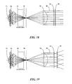
- FIG. 18 and FIG. 19 Another optical system for a luminaire used in non-imaging illumination applications, as shown in FIG. 18 and FIG. 19, includes a lamp 71 optically coupled to a reflector 72 , and a collimating lens 79 forming a substantially columnar light beam.
- the reflector 72 may be an elliptical reflector as shown, focusing light rays to a point at which a field stop 78 is located.
- a color filter system 75 may be located between the reflector 72 and the field stop 78 , and may comprise, for example, a set of color filter wheels as shown in British Pat. No. 629,266.
- a zoomable beamspreader comprising first and second multiple-lens arrays 20 , 30 is provided downstream of the collimating lens 79 .
- a suitable output lens may be provided to cover the exit aperture of the luminaire, the housing of which is not shown but may comprise any suitable structure for supporting the optical system.
- a typical luminaire structure is shown, for example, in U.S. Pat. No. D 366,712, or U.S. Pat. No. D 439,356.
- the system as shown in FIG. 18 illustrates the performance of the beam spreader of the present invention in the zero-power state as multiple lens arrays 20 , 30 are positioned at the preferred separation distance D 0 , to project a light beam 80 having only a small, negligible angle of beam divergence.
- the system as shown in FIG. 19 illustrates the performance of the beam spreader of the present invention as the multiple-lens arrays 20 , 30 are separated by some greater distance along the optical axis of the system so as to increase the angle of beam divergence.
Abstract
Description
Claims (19)
Priority Applications (1)
| Application Number | Priority Date | Filing Date | Title |
|---|---|---|---|
| US10/229,668 US6809869B2 (en) | 2002-08-28 | 2002-08-28 | Zoomable beamspreader for non-imaging illumination applications |
Applications Claiming Priority (1)
| Application Number | Priority Date | Filing Date | Title |
|---|---|---|---|
| US10/229,668 US6809869B2 (en) | 2002-08-28 | 2002-08-28 | Zoomable beamspreader for non-imaging illumination applications |
Publications (2)
| Publication Number | Publication Date |
|---|---|
| US20040042085A1 US20040042085A1 (en) | 2004-03-04 |
| US6809869B2 true US6809869B2 (en) | 2004-10-26 |
Family
ID=31976288
Family Applications (1)
| Application Number | Title | Priority Date | Filing Date |
|---|---|---|---|
| US10/229,668 Expired - Lifetime US6809869B2 (en) | 2002-08-28 | 2002-08-28 | Zoomable beamspreader for non-imaging illumination applications |
Country Status (1)
| Country | Link |
|---|---|
| US (1) | US6809869B2 (en) |
Cited By (14)
| Publication number | Priority date | Publication date | Assignee | Title |
|---|---|---|---|---|
| US20050135096A1 (en) * | 2003-12-22 | 2005-06-23 | Schott Glas | Fresnel spotlight |
| EP1731955A1 (en) | 2005-06-09 | 2006-12-13 | Sony Ericsson Mobile Communications AB | Flash device for an electronic equipment for a wireless communication system and method for operating a flash device for an electronic equipment |
| USRE41240E1 (en) * | 1999-03-26 | 2010-04-20 | Genlyte Thomas Group Llc | Zoomable beamspreader with matched optical surfaces for non-imaging illumination applications |
| US20100149820A1 (en) * | 2008-09-12 | 2010-06-17 | Light Prescriptions Innovators,Llc | Zoom luminaire with compact non-imaging lens-mirror optics |
| US20100165628A1 (en) * | 2008-12-29 | 2010-07-01 | Davydov Maxim Yur Evich | Light source |
| US20100246196A1 (en) * | 2009-03-31 | 2010-09-30 | Robe Lighting S.R.O. | Lens slide for an automated luminaire |
| US20110103073A1 (en) * | 2009-09-11 | 2011-05-05 | Robe Lighting S.R.O. | Beam shaper |
| US20110163334A1 (en) * | 2008-09-16 | 2011-07-07 | Koninklijke Philips Electronics N.V. | Colour mixing method for consistent colour quality |
| US20130155671A1 (en) * | 2010-09-10 | 2013-06-20 | Koninklijke Philips Electronics N.V. | Arrangement for spot illumination |
| US20140233244A1 (en) * | 2013-02-19 | 2014-08-21 | Pavel Jurik | Lens slide for an automated luminaire |
| US20170153004A1 (en) * | 2014-06-26 | 2017-06-01 | Philips Lighting Holding B.V. | Optical arrangement, lighting device and illumination method |
| US9989217B2 (en) | 2012-03-18 | 2018-06-05 | Robe Lighting S.R.O. | Beam framing system for an automated luminaire |
| US10359636B2 (en) | 2009-09-11 | 2019-07-23 | Robe Lighting S.R.O. | Beam shaper |
| CN112285871A (en) * | 2020-11-11 | 2021-01-29 | 同济大学 | Big and small double-focusing movable lens group and metal surface exposure SLM system |
Families Citing this family (13)
| Publication number | Priority date | Publication date | Assignee | Title |
|---|---|---|---|---|
| US6912090B2 (en) * | 2003-03-18 | 2005-06-28 | Lucent Technologies Inc. | Adjustable compound microlens apparatus with MEMS controller |
| US7742512B2 (en) * | 2004-02-02 | 2010-06-22 | Raytheon Company | Scalable laser with robust phase locking |
| KR101194972B1 (en) * | 2005-09-30 | 2012-10-25 | 리모 파텐트페어발퉁 게엠베하 운트 코. 카게 | Device for homogenising light |
| JP2007171319A (en) * | 2005-12-20 | 2007-07-05 | Samsung Electronics Co Ltd | Illumination optical system, illumination unit and image projector using the optical system |
| EP2309296A1 (en) * | 2009-09-11 | 2011-04-13 | GLP German Light Products GmbH | Support structure for a range of lenses, lens, lens system and optical system |
| CN102563397B (en) * | 2010-12-31 | 2015-01-07 | 南京迈瑞生物医疗电子有限公司 | Operating lamp and its light transmission cover and light spot regulation method |
| ITVI20120134A1 (en) * | 2012-06-05 | 2013-12-06 | Beghelli Spa | ADJUSTABLE BRIGHT OPTIONAL LIGHTING SYSTEM FOR LED LIGHTING DEVICES |
| US20140022794A1 (en) * | 2012-07-20 | 2014-01-23 | Ledil Oy | Lens arrangement and illuminator housing |
| TW201439627A (en) * | 2013-04-02 | 2014-10-16 | Hon Hai Prec Ind Co Ltd | Light emitting device and backlight module |
| ES1079153Y (en) * | 2013-04-10 | 2013-07-30 | Linares Encarnacion Bermudez | LIGHT TRANSMISSION AND DISTRIBUTION DEVICE APPLICABLE TO VEHICLE HEADLIGHTS |
| US11199306B2 (en) * | 2017-08-02 | 2021-12-14 | Erco Gmbh | Lamp |
| US10901227B2 (en) | 2018-02-21 | 2021-01-26 | American Sterilizer Company | Refractive lens array assembly |
| DE102019119682A1 (en) * | 2019-07-19 | 2021-01-21 | Erco Gmbh | Building light |
Citations (38)
| Publication number | Priority date | Publication date | Assignee | Title |
|---|---|---|---|---|
| US2076240A (en) | 1934-10-25 | 1937-04-06 | Century Lighting Equipment Inc | Spot and floodlight projector apparatus |
| US2650292A (en) | 1949-07-12 | 1953-08-25 | Strong Electric Corp | Lamp having a reflector, two lenses, and means to vary the distance between them |
| US2950382A (en) | 1956-12-17 | 1960-08-23 | Strong Electric Corp | Projection lamp |
| US3302016A (en) | 1964-08-21 | 1967-01-31 | Textron Electronics Inc | Optical collimating system |
| US3428800A (en) | 1965-12-10 | 1969-02-18 | Sylvania Electric Prod | Spotlight lamp |
| US3484599A (en) | 1967-01-03 | 1969-12-16 | William D Little | Optical projection system |
| US3594566A (en) | 1969-10-13 | 1971-07-20 | Kneisley Electronic Co | Light projector |
| US3665179A (en) | 1968-05-28 | 1972-05-23 | British Lighting Ind Ltd | Lighting system |
| US4462067A (en) | 1983-04-08 | 1984-07-24 | Altman Stage Lighting Co., Inc. | Spotlight and adjusting system |
| US4519020A (en) | 1983-11-14 | 1985-05-21 | Little William D | Variable magnification stage light |
| US4602321A (en) | 1985-02-28 | 1986-07-22 | Vari-Lite, Inc. | Light source having automatically variable hue, saturation and beam divergence |
| US4630902A (en) | 1981-07-31 | 1986-12-23 | Canon Kabushiki Kaisha | Compound eye optical system having a variable magnification function |
| US4632522A (en) | 1983-10-31 | 1986-12-30 | Mita Industrial Co., Ltd. | Optical system of variable magnification and a method for varying magnification of the same |
| US4709311A (en) | 1986-07-16 | 1987-11-24 | Vari-Lite, Inc. | Lens carrier |
| US4739456A (en) | 1986-12-12 | 1988-04-19 | Little William D | High intensity pattern/follow spot projector |
| US4779176A (en) | 1986-07-16 | 1988-10-18 | Vari-Lite, Inc. | Light pattern generator |
| US4867514A (en) | 1985-11-12 | 1989-09-19 | Hydro Fuels, Inc. | Systems for deviating and (optionally) converging radiation |
| US5029992A (en) | 1988-07-26 | 1991-07-09 | Morpheus Lights, Inc. | Motor-controlled lens system |
| US5237367A (en) | 1990-12-27 | 1993-08-17 | Nikon Corporation | Illuminating optical system and exposure apparatus utilizing the same |
| US5404283A (en) | 1992-03-31 | 1995-04-04 | Phoenix Products Company, Inc. | Outdoor framing projector |
| JPH0883743A (en) | 1994-09-09 | 1996-03-26 | Nikon Corp | Lighting optical device |
| US5581379A (en) | 1993-02-15 | 1996-12-03 | Omron Corporation | Rectangular based convex microlenses surrounded within a frame and method of making |
| US5598281A (en) | 1993-11-19 | 1997-01-28 | Alliedsignal Inc. | Backlight assembly for improved illumination employing tapered optical elements |
| EP0757280A2 (en) | 1995-08-01 | 1997-02-05 | Eastman Kodak Company | Zoom flash with transversely displaceable wave-lens elements for adjusting the scene coverage angle of the light beam |
| US5612821A (en) | 1995-06-15 | 1997-03-18 | United Technologies Corporation | Micro lens system for controlling an optical beam pattern |
| US5684567A (en) | 1992-06-25 | 1997-11-04 | Canon Kabushiki Kaisha | Exposure apparatus and device manufacturing method for projecting light from a secondary light source onto a mask or pattern |
| US5774273A (en) | 1996-08-23 | 1998-06-30 | Vari-Lite, Inc. | Variable-geometry liquid-filled lens apparatus and method for controlling the energy distribution of a light beam |
| US5775799A (en) | 1994-11-17 | 1998-07-07 | David W. Cunningham | Lighting device incorporating a zoomable beamspreader |
| US5786939A (en) | 1996-02-26 | 1998-07-28 | Fuji Photo Optical Co., Ltd. | Illumination optical system |
| US5805340A (en) | 1996-11-22 | 1998-09-08 | Shawn L. Kelly | Optical modulator and system having tunable image enhancement |
| US5850310A (en) | 1995-09-27 | 1998-12-15 | Carl-Zeiss-Stiftung | Zoom device |
| US6059428A (en) | 1997-02-19 | 2000-05-09 | C.R.F. Societa Consortile Per Azioni | Lighting device, particularly a motor vehicle headlamp, having a micro-lens structure with a flexible support for adjusting the emitted light beam |
| US6115181A (en) | 1996-11-22 | 2000-09-05 | 3M Innovative Properties Company | Variable beam splitter having opposed alternating convex and concave lens structures |
| US6212011B1 (en) | 1996-09-05 | 2001-04-03 | Vitaly Lissotschenko | Optical beam-shaping system |
| US6246526B1 (en) | 1998-11-30 | 2001-06-12 | Canon Kabushiki Kaisha | Light irradiating apparatus and image displaying apparatus |
| US6282027B1 (en) * | 1999-03-26 | 2001-08-28 | Vari-Lite, Inc. | Zoomable beamspreader with matched optical surfaces for non-imaging illumination applications |
| US6344929B1 (en) | 1999-02-19 | 2002-02-05 | Canon Kabushiki Kaisha | Illumination apparatus and projection type display apparatus |
| US6366407B2 (en) | 1999-07-12 | 2002-04-02 | Eastman Kodak Company | Lenticular image product with zoom image effect |
-
2002
- 2002-08-28 US US10/229,668 patent/US6809869B2/en not_active Expired - Lifetime
Patent Citations (39)
| Publication number | Priority date | Publication date | Assignee | Title |
|---|---|---|---|---|
| US2076240A (en) | 1934-10-25 | 1937-04-06 | Century Lighting Equipment Inc | Spot and floodlight projector apparatus |
| US2650292A (en) | 1949-07-12 | 1953-08-25 | Strong Electric Corp | Lamp having a reflector, two lenses, and means to vary the distance between them |
| US2950382A (en) | 1956-12-17 | 1960-08-23 | Strong Electric Corp | Projection lamp |
| US3302016A (en) | 1964-08-21 | 1967-01-31 | Textron Electronics Inc | Optical collimating system |
| US3428800A (en) | 1965-12-10 | 1969-02-18 | Sylvania Electric Prod | Spotlight lamp |
| US3484599A (en) | 1967-01-03 | 1969-12-16 | William D Little | Optical projection system |
| US3665179A (en) | 1968-05-28 | 1972-05-23 | British Lighting Ind Ltd | Lighting system |
| US3594566A (en) | 1969-10-13 | 1971-07-20 | Kneisley Electronic Co | Light projector |
| US4630902A (en) | 1981-07-31 | 1986-12-23 | Canon Kabushiki Kaisha | Compound eye optical system having a variable magnification function |
| US4462067A (en) | 1983-04-08 | 1984-07-24 | Altman Stage Lighting Co., Inc. | Spotlight and adjusting system |
| US4632522A (en) | 1983-10-31 | 1986-12-30 | Mita Industrial Co., Ltd. | Optical system of variable magnification and a method for varying magnification of the same |
| US4519020A (en) | 1983-11-14 | 1985-05-21 | Little William D | Variable magnification stage light |
| US4602321A (en) | 1985-02-28 | 1986-07-22 | Vari-Lite, Inc. | Light source having automatically variable hue, saturation and beam divergence |
| US4867514A (en) | 1985-11-12 | 1989-09-19 | Hydro Fuels, Inc. | Systems for deviating and (optionally) converging radiation |
| US4779176B1 (en) | 1986-07-16 | 1991-08-27 | Vari Lite Inc | |
| US4709311A (en) | 1986-07-16 | 1987-11-24 | Vari-Lite, Inc. | Lens carrier |
| US4779176A (en) | 1986-07-16 | 1988-10-18 | Vari-Lite, Inc. | Light pattern generator |
| US4739456A (en) | 1986-12-12 | 1988-04-19 | Little William D | High intensity pattern/follow spot projector |
| US5029992A (en) | 1988-07-26 | 1991-07-09 | Morpheus Lights, Inc. | Motor-controlled lens system |
| US5237367A (en) | 1990-12-27 | 1993-08-17 | Nikon Corporation | Illuminating optical system and exposure apparatus utilizing the same |
| US5404283A (en) | 1992-03-31 | 1995-04-04 | Phoenix Products Company, Inc. | Outdoor framing projector |
| US5684567A (en) | 1992-06-25 | 1997-11-04 | Canon Kabushiki Kaisha | Exposure apparatus and device manufacturing method for projecting light from a secondary light source onto a mask or pattern |
| US5581379A (en) | 1993-02-15 | 1996-12-03 | Omron Corporation | Rectangular based convex microlenses surrounded within a frame and method of making |
| US5598281A (en) | 1993-11-19 | 1997-01-28 | Alliedsignal Inc. | Backlight assembly for improved illumination employing tapered optical elements |
| JPH0883743A (en) | 1994-09-09 | 1996-03-26 | Nikon Corp | Lighting optical device |
| US5775799A (en) | 1994-11-17 | 1998-07-07 | David W. Cunningham | Lighting device incorporating a zoomable beamspreader |
| US5612821A (en) | 1995-06-15 | 1997-03-18 | United Technologies Corporation | Micro lens system for controlling an optical beam pattern |
| EP0757280A2 (en) | 1995-08-01 | 1997-02-05 | Eastman Kodak Company | Zoom flash with transversely displaceable wave-lens elements for adjusting the scene coverage angle of the light beam |
| US5850310A (en) | 1995-09-27 | 1998-12-15 | Carl-Zeiss-Stiftung | Zoom device |
| US5786939A (en) | 1996-02-26 | 1998-07-28 | Fuji Photo Optical Co., Ltd. | Illumination optical system |
| US5774273A (en) | 1996-08-23 | 1998-06-30 | Vari-Lite, Inc. | Variable-geometry liquid-filled lens apparatus and method for controlling the energy distribution of a light beam |
| US6212011B1 (en) | 1996-09-05 | 2001-04-03 | Vitaly Lissotschenko | Optical beam-shaping system |
| US5805340A (en) | 1996-11-22 | 1998-09-08 | Shawn L. Kelly | Optical modulator and system having tunable image enhancement |
| US6115181A (en) | 1996-11-22 | 2000-09-05 | 3M Innovative Properties Company | Variable beam splitter having opposed alternating convex and concave lens structures |
| US6059428A (en) | 1997-02-19 | 2000-05-09 | C.R.F. Societa Consortile Per Azioni | Lighting device, particularly a motor vehicle headlamp, having a micro-lens structure with a flexible support for adjusting the emitted light beam |
| US6246526B1 (en) | 1998-11-30 | 2001-06-12 | Canon Kabushiki Kaisha | Light irradiating apparatus and image displaying apparatus |
| US6344929B1 (en) | 1999-02-19 | 2002-02-05 | Canon Kabushiki Kaisha | Illumination apparatus and projection type display apparatus |
| US6282027B1 (en) * | 1999-03-26 | 2001-08-28 | Vari-Lite, Inc. | Zoomable beamspreader with matched optical surfaces for non-imaging illumination applications |
| US6366407B2 (en) | 1999-07-12 | 2002-04-02 | Eastman Kodak Company | Lenticular image product with zoom image effect |
Cited By (24)
| Publication number | Priority date | Publication date | Assignee | Title |
|---|---|---|---|---|
| USRE41240E1 (en) * | 1999-03-26 | 2010-04-20 | Genlyte Thomas Group Llc | Zoomable beamspreader with matched optical surfaces for non-imaging illumination applications |
| US20050135096A1 (en) * | 2003-12-22 | 2005-06-23 | Schott Glas | Fresnel spotlight |
| EP1731955A1 (en) | 2005-06-09 | 2006-12-13 | Sony Ericsson Mobile Communications AB | Flash device for an electronic equipment for a wireless communication system and method for operating a flash device for an electronic equipment |
| WO2006131275A1 (en) * | 2005-06-09 | 2006-12-14 | Sony Ericsson Mobile Communications Ab | Flash device for an electronic equipment for a wireless comminication system and method for operating a flash device for an electronic equipment |
| US20080278925A1 (en) * | 2005-06-09 | 2008-11-13 | Mats Wernersson | Flash Device for an Electronic Equipment for a Wireless Communication System and Method for Operating a Flash Device for an Electronic Equipment |
| CN101194206B (en) * | 2005-06-09 | 2010-06-09 | 索尼爱立信移动通讯股份有限公司 | Flash device for an electronic equipment for a wireless communication system and method for operating a flash device for an electronic equipment |
| US20100149820A1 (en) * | 2008-09-12 | 2010-06-17 | Light Prescriptions Innovators,Llc | Zoom luminaire with compact non-imaging lens-mirror optics |
| US8075162B2 (en) | 2008-09-12 | 2011-12-13 | Light Prescriptions Innovators, Llc | Zoom luminaire with compact non-imaging lens-mirror optics |
| US20110163334A1 (en) * | 2008-09-16 | 2011-07-07 | Koninklijke Philips Electronics N.V. | Colour mixing method for consistent colour quality |
| US8147095B2 (en) * | 2008-12-29 | 2012-04-03 | Davydov Maxim Yur Evich | Light source |
| US20100165628A1 (en) * | 2008-12-29 | 2010-07-01 | Davydov Maxim Yur Evich | Light source |
| US8376591B2 (en) * | 2009-03-31 | 2013-02-19 | Robe Lighting S.R.O. | Lens slide for an automated luminaire |
| US20100246196A1 (en) * | 2009-03-31 | 2010-09-30 | Robe Lighting S.R.O. | Lens slide for an automated luminaire |
| US10359636B2 (en) | 2009-09-11 | 2019-07-23 | Robe Lighting S.R.O. | Beam shaper |
| US20110103073A1 (en) * | 2009-09-11 | 2011-05-05 | Robe Lighting S.R.O. | Beam shaper |
| US11300797B2 (en) | 2009-09-11 | 2022-04-12 | Robe Lighting S.R.O. | Beam shaper |
| US20130155671A1 (en) * | 2010-09-10 | 2013-06-20 | Koninklijke Philips Electronics N.V. | Arrangement for spot illumination |
| US9169997B2 (en) * | 2010-09-10 | 2015-10-27 | Koninklijke Philips N.V. | Arrangement for spot illumination |
| US9989217B2 (en) | 2012-03-18 | 2018-06-05 | Robe Lighting S.R.O. | Beam framing system for an automated luminaire |
| US20140233244A1 (en) * | 2013-02-19 | 2014-08-21 | Pavel Jurik | Lens slide for an automated luminaire |
| US20170153004A1 (en) * | 2014-06-26 | 2017-06-01 | Philips Lighting Holding B.V. | Optical arrangement, lighting device and illumination method |
| US10533726B2 (en) * | 2014-06-26 | 2020-01-14 | Signify Holding B.V. | Optical arrangement, lighting device and illumination method |
| CN112285871A (en) * | 2020-11-11 | 2021-01-29 | 同济大学 | Big and small double-focusing movable lens group and metal surface exposure SLM system |
| CN112285871B (en) * | 2020-11-11 | 2022-04-05 | 同济大学 | Big and small double-focusing movable lens group and metal surface exposure SLM system |
Also Published As
| Publication number | Publication date |
|---|---|
| US20040042085A1 (en) | 2004-03-04 |
Similar Documents
| Publication | Publication Date | Title |
|---|---|---|
| US6809869B2 (en) | Zoomable beamspreader for non-imaging illumination applications | |
| USRE41240E1 (en) | Zoomable beamspreader with matched optical surfaces for non-imaging illumination applications | |
| US5774273A (en) | Variable-geometry liquid-filled lens apparatus and method for controlling the energy distribution of a light beam | |
| EP2177816B1 (en) | A ligth collection system for an led luminaire | |
| US6817737B2 (en) | Light projector | |
| EP3557126B1 (en) | Optomechanical system and method for controlling the photometric distribution of luminaires and corresponding luminaires | |
| EP3052982B1 (en) | Collimation and homogenization system for an led luminaire | |
| EP2856236B1 (en) | Collimation and homogenization system for an led luminaire | |
| WO2016116290A1 (en) | Optical device with a collimator and lenslet arrays | |
| US20080192473A1 (en) | Fooldlight With Variable Beam | |
| JP2000147216A (en) | Optically transparent film | |
| WO2012004760A1 (en) | Optical zoom assembly for a non-imaging illumination application and luminaire using same | |
| ITMI20121399A1 (en) | LED LIGHTING LAMP | |
| CN111936788A (en) | Configurable luminaire and component | |
| US7452105B2 (en) | Optical system for a wash light | |
| GB2474921A (en) | Lens element with facets at different angles relative to one another | |
| US10544919B2 (en) | Optical arrangement, lighting system and illumination method | |
| KR102140878B1 (en) | Optics device of head lamp and head lamp for vehicle using the same | |
| EP2881654A2 (en) | Lighting device | |
| CN112666777B (en) | Light source field angle adjusting system | |
| US11149920B2 (en) | Oval-condenser zoom with independent axis adjustment | |
| CN111750327A (en) | Projection assembly for vehicle dipped headlight, vehicle dipped headlight and vehicle | |
| GB2594155A (en) | Zoom mechanism for a light fixture | |
| CN114901991A (en) | Illumination device collector and converging optical system | |
| CN113874657A (en) | Light emitting device |
Legal Events
| Date | Code | Title | Description |
|---|---|---|---|
| AS | Assignment |
Owner name: VARI-LITE, INC., TEXAS Free format text: ASSIGNMENT OF ASSIGNORS INTEREST;ASSIGNOR:HOUGH, THOMAS A.;REEL/FRAME:013238/0041 Effective date: 20020828 |
|
| AS | Assignment |
Owner name: GENLYTE THOMAS GROUP LLC, KENTUCKY Free format text: ASSIGNMENT OF ASSIGNORS INTEREST;ASSIGNOR:VARI-LITE, INC.;REEL/FRAME:014851/0511 Effective date: 20021118 |
|
| STCF | Information on status: patent grant |
Free format text: PATENTED CASE |
|
| CC | Certificate of correction | ||
| FPAY | Fee payment |
Year of fee payment: 4 |
|
| SULP | Surcharge for late payment | ||
| FPAY | Fee payment |
Year of fee payment: 8 |
|
| FPAY | Fee payment |
Year of fee payment: 12 |
|
| AS | Assignment |
Owner name: PHILIPS LIGHTING NORTH AMERICA CORPORATION, NEW JE Free format text: ASSIGNMENT OF ASSIGNORS INTEREST;ASSIGNOR:GENLYTE THOMAS GROUP LLC;REEL/FRAME:041085/0851 Effective date: 20160810 |
|
| AS | Assignment |
Owner name: SIGNIFY NORTH AMERICA CORPORATION, NETHERLANDS Free format text: CHANGE OF NAME;ASSIGNOR:PHILIPS LIGHTING NORTH AMERICA CORPORATION;REEL/FRAME:050836/0669 Effective date: 20190128 |