US6609178B1 - Selective validation for queued multimodal locking services - Google Patents
Selective validation for queued multimodal locking services Download PDFInfo
- Publication number
- US6609178B1 US6609178B1 US09/723,606 US72360600A US6609178B1 US 6609178 B1 US6609178 B1 US 6609178B1 US 72360600 A US72360600 A US 72360600A US 6609178 B1 US6609178 B1 US 6609178B1
- Authority
- US
- United States
- Prior art keywords
- lock
- processor
- shared resource
- mode
- procedure
- Prior art date
- Legal status (The legal status is an assumption and is not a legal conclusion. Google has not performed a legal analysis and makes no representation as to the accuracy of the status listed.)
- Expired - Lifetime, expires
Links
Images


Classifications
-
- G—PHYSICS
- G06—COMPUTING; CALCULATING OR COUNTING
- G06F—ELECTRIC DIGITAL DATA PROCESSING
- G06F9/00—Arrangements for program control, e.g. control units
- G06F9/06—Arrangements for program control, e.g. control units using stored programs, i.e. using an internal store of processing equipment to receive or retain programs
- G06F9/46—Multiprogramming arrangements
- G06F9/52—Program synchronisation; Mutual exclusion, e.g. by means of semaphores
- G06F9/526—Mutual exclusion algorithms
-
- G—PHYSICS
- G06—COMPUTING; CALCULATING OR COUNTING
- G06F—ELECTRIC DIGITAL DATA PROCESSING
- G06F12/00—Accessing, addressing or allocating within memory systems or architectures
- G06F12/02—Addressing or allocation; Relocation
- G06F12/08—Addressing or allocation; Relocation in hierarchically structured memory systems, e.g. virtual memory systems
- G06F12/12—Replacement control
- G06F12/121—Replacement control using replacement algorithms
- G06F12/123—Replacement control using replacement algorithms with age lists, e.g. queue, most recently used [MRU] list or least recently used [LRU] list
-
- G—PHYSICS
- G06—COMPUTING; CALCULATING OR COUNTING
- G06F—ELECTRIC DIGITAL DATA PROCESSING
- G06F12/00—Accessing, addressing or allocating within memory systems or architectures
- G06F12/02—Addressing or allocation; Relocation
- G06F12/08—Addressing or allocation; Relocation in hierarchically structured memory systems, e.g. virtual memory systems
- G06F12/0802—Addressing of a memory level in which the access to the desired data or data block requires associative addressing means, e.g. caches
- G06F12/0866—Addressing of a memory level in which the access to the desired data or data block requires associative addressing means, e.g. caches for peripheral storage systems, e.g. disk cache
Definitions
- This invention relates generally to a method and apparatus for improving performance in systems where multiple processors contend for control of a shared resource through a lock associated with the shared resource, and more particularly to a method and apparatus for improving performance in intelligent data storage systems.
- Many high-performance storage systems are intelligent data storage systems which may be accessible by multiple host computers. These may include, in addition to one or more storage device arrays, a number of intelligent controllers for controlling the various aspects of the data transfers associated with the storage system.
- host controllers may provide the interface between the host computers and the storage system, and device controllers may be used to manage the transfer of data to and from an associated array of storage devices (e.g. disk drives). Often, the arrays may be accessed by multiple hosts and controllers.
- advanced storage systems such as the SYMMETRIX® storage systems manufactured by EMC Corporation, generally include a global memory which typically shared by the controllers in the system.
- the memory may be used as a staging area (or cache) for the data transfers between the storage devices and the host computers and may provide a communications path which buffers data transfer between the various controllers.
- Various communication channels such as busses, backplanes or networks, link the controllers to one another and the global memory, the host controllers to the host computers, and the disk controllers to the storage devices.
- the '539 patent Vishlitzky et al, U.S. Pat. No. 5,592,492 issued Jan. 7, 1997, (hereinafter “the '492 patent”), Yanai et al, U.S. Pat. No. 5,664,144 issued Sep. 2, 1997 (hereinafter “the '144 patent), and Vishlitzky et al, U.S. Pat. No. 5,787,473 issued Jul. 28, 1998, (hereinafter “the '473 patent”), all of which are herein incorporated in their entirety by reference.
- the systems described therein allow the controllers to act independently to perform different processing tasks and provide for distributed management of the global memory resources by the controllers.
- each of the controllers may act independently, there may be contention for certain of the shared memory resources within the system.
- the consistency of the data contained in some portions of global memory may be maintained by requiring each controller to lock those data structures which require consistency while it is performing any operations on them which are supposed to be atomic.
- multimodal locks which permit the requestor to identify the kind of resource access desired by the requester and the degree of resource sharing which its transaction can tolerate, can be useful in improving system performance and avoiding deadlocks, but providing a lock override which is suitable for a multimodal lock is quite difficult. If, for example, one lock mode is set to allow unusually long transactions, a timeout set to accommodate normal transactions will cut the long ones off in midstream while a timeout set to accommodate the long transactions will allow failures occurring during normal transactions to go undetected for excessively long periods. Moreover, timeouts are competitive procedures which, in certain circumstances, undesirably offset the cooperative advantages of a queued lock. Because of the complexities introduced by multifeatured locks, it is desirable to validate features and modes which create particularly significant drains on system resources, such as long timeout modes, but introducing additional validation features can itself load system resources to the point where the system efficiency suffers.
- a lock mechanism for managing shared resources in a data processing system is provided.
- a method for providing queued, multimodal, self-validating locking and unlocking services for managing a shared resource in a data processing system is provided.
- the lock mechanism is multimodal and self-validating.
- One or more supplemental validation procedures may be selectively associated with certain lock modes.
- lock modes which constitute a particularly heavy drain on system resources may be extensively validated after the lock is reserved but before the requestor commits to locking the shared resource in these modes to avoid committing the system in error, while the drain on system resources which would be created by validating every lock transaction to a comparably high level may be avoided.
- the method also includes providing for each processor a lock services procedure including at least fist and second lock mode procedures, a lock mode selection procedure for selecting one from the lock mode procedures by a successful lock requester, a queuing procedure for unsuccessful lock requesters, locking and unlocking procedures for locking and unlocking the shared resource in the selected lock mode by a successful lock requestor, and a supplemental validation procedure selectively associated with the second lock mode for validating the lock by a successful lock requestor.
- the method also includes the step of selecting one from the lock modes by a requesting processor.
- the method also includes the step of, in a single atomic operation by the requesting processor, examining the contents of the main lock data structure to determine if another requesting processor has previously locked the shared resource and if the lock contents are valid, and writing data to the main lock data structure to establish its place in a queue of requesters for subsequent locks on the shared resource if some other requesting processor has previously locked the shared resource and the lock contents are also valid, or writing data to the main lock data structure to reserve and validate the lock and to identify the first lock mode if the lock contents are invalid or if no other requesting processor has previously locked the shared resource.
- the requesting processor executes the supplemental validation procedure by the requesting processor to validate the lock allocation to that requesting processor. If the supplemental validation procedure does validate the lock allocation to that requesting processor, then the requesting processor writes data to the main lock data structure to identify the second lock mode, but if it does not, the requesting processor does not enter the second lock mode.
- a main lock data structure responsive to these lock services procedures and associated with the shared resource, is implemented in the shared memory accessible over one or more second common communications channels to all of the processors.
- the main lock data structure provides, in a single atomic structure, the resources needed to lock a shared resource, identify one of the at least two lock modes, establish a queue of unsuccessful lock requesters, and validate the existence of the lock, Resources are also provided to validate the identity of the successful lock requestor in connection with certain transactions.
- the lock services procedure also enables each processor, in a single transaction, to request locks on the shared resource, to validate the existence of a lock in the main lock data structure, to request locks on the shared resource, to lock the shared resource if its request is successful and to establish a place in a queue of requestors for subsequent locks on the shared resource if its request is unsuccessful.
- Each requesting processor is operable in accordance with its lock services procedure to select one from the lock modes.
- Each requesting processor is also operable in accordance with its lock services procedure in a single atomic operation, to examine the contents of the main lock data structure to determine if another requesting processor has previously locked the shared resource and if the lock contents are valid, and to write data to the main lock data structure to establish its place in a queue of requesters for subsequent locks on the shared resource if some other requesting processor has previously locked the shared resource and the lock contents are also valid, or to write data to the main lock data structure to reserve and validate the lock and to identify the first lock mode if the lock contents are invalid or if no other requesting processor has previously locked the shared resource.
- the requesting processor is operable to execute the supplemental validation procedure in order to validate the lock allocation to that requesting processor. If the supplemental validation procedure does validate the lock allocation to that requesting processor, then, the requesting processor is operable to write data to the main lock data structure to identify the second lock mode, but if it does not, the requesting processor does not enter the second lock mode.
- data may be written to lock the shared resource in a first one of at least two lock modes as a part of this atomic operation or to lock the shared resource in a second one of at least two lock modes in a subsequent atomic operation following a supplemental validation procedure.
- multiple processes running on a single processor may in some aspects act as requesters and a lock allocation process or procedure may be invoked by each of these processes, but the operation of the invention is otherwise as described above.
- FIG. 1 is a block diagram of a computer system including a shared resource and incorporating the present invention.
- FIG. 2 is a more detailed block diagram of the computer system of FIG. 1 including an intelligent mass storage system.
- FIG. 3 is a schematic diagram of the main lock data structure used to implement the invention in the system described herein.
- FIG. 4 is a schematic diagram of the auxiliary lock data structure used to implement the invention in some aspects of the system described herein.
- FIG. 5 is a flowchart illustrating steps used to enter the lock request queue, and to poll for and obtain the lock during normal operation of the system described herein.
- FIG. 6 is a flowchart illustrating steps used to perform a timeout lock override procedure associated with a selected one of the lock modes implemented in the system described herein.
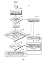
- FIG. 7 is a flowchart illustrating steps used to take the lock, to select one of the lock modes, to perform a supplemental validation associated with the selected lock mode, and to initialize a cooperative lock override procedure associated with the selected lock mode implemented in the system described herein.
- FIG. 8 is a flowchart illustrating steps used to perform the cooperative lock override procedure corresponding to a selected one of the lock modes in the system described herein.
- FIG. 9 is a flowchart illustrating steps used to unlock the lock during normal operation of the system described herein.
- computer system 10 is shown to include, among other things, a plurality of processors 1 a- 1 n, running processes A-N, coupled to a shared resource 4 via one or more first common communication channels 3 a-n and to a shared memory 2 via one or more second common communication channels 7 a-n.
- processors 1 a- 1 n may request access to shared resource 4 in order to execute their processes A-N.
- the processors are actual or virtual digital processing units which include one or more CPU's and additional local memory 5 a-n.
- processor 1 a may be an intelligent device controller, an open-systems computer, a personal computer, a server, an intelligent host controller or a virtual system residing on a mainframe computer. Since each of the computer systems just mentioned typically communicates using a specific communication protocol, each of the first and second common communication channels will correspondingly be those channels specific to the computer system to which they are coupled. That is for example, assuming processor 1 b is an open-systems type server (e.g. running the UNIX Operating System), channel 3 or 7 would typically be a SCSI type communications bus or a fibber-channel communications path. All communications over channel 3 or 7 would therefore adhere to the respective SCSI or fibre-channel communications protocols.
- open-systems type server e.g. running the UNIX Operating System
- Processes A-N may be, for example, procedures run by the processors, operating system processes or higher level applications.
- the processors may run other processes not involving shared resource 4 .
- the invention may also be applicable to multiple processes contending for a shared resource but running on a single processor, although this aspect is not illustrated in the drawings.
- system 10 also provides a queued lock associated with shared resource 4 .
- the queued lock is implemented by a main lock data structure, 30 and, in some aspects, an auxiliary lock data structure, 40 , both further described below, in shared memory 2 and a lock services procedure 6 a- 6 n running on each of processors 1 a- 1 n, respectively.
- the lock data structures, 30 and 40 must be implemented in a section of memory that is accessible by all of the processors which might need access to the shared resource, although they need not be on the same media as the shared resource.
- the procedures which allocate the lock may be centralized or distributed. In the intelligent data processing systems described above, the lock services procedures are typically distributed among the various intelligent controllers.
- the main lock data structure, 30 is used for queuing, mode designation, and transfers of control. It is an atomic data structure which indicates the queue position of the current holder of the lock, the next available position in the queue of subsequent lock requests, the lock mode employed by the current successful lock requestor, and validation information which may be used to identify certain protocol failures requiring lock overrides. Resources may also be provided in the main lock data structure to validate the identity of the successful lock requestor in connection with certain transactions.
- the auxiliary lock data structure, 40 is used for validation and may be used to identify additional protocol failures requiring lock overrides, for example, those associated with a particular lock mode.
- the auxiliary lock data structure, 40 may be a single entry, the entry being a single atomic structure, or it may be an array which includes an entry for each processor, each entry being a single atomic structure.
- Each entry includes the resources needed to identify the successful lock requestor's place in a queue of requesters and to identify the successful lock requestor.
- Each processor typically invokes its lock services procedure, for example procedure 6 b for processor 1 b, before starting a transaction on the shared resource 4 , and may obtain a lock on the shared resource 4 if it is available. Only after a successful requestor from among the processors obtains the lock will that processor perform its transaction on shared resource 4 .
- each of the lock services procedures 6 a- 6 n incorporates, in accordance with the present invention, a lock contention procedure, at least two lock mode procedures, procedures for locking, mode designation and unlocking operations by a successful lock requestor in normal operation, algorithms for arbitrating among multiple requests for locks on the shared resource 4 from multiple unsuccessful requestors 1 a- 1 n, and a polling procedure for allowing a previously unsuccessful requestor to determine its current status, and, in some aspects, lock override procedures and supplemental lock validation procedures associated with various lock modes, all of which will be further described below.
- the shared resource 4 of computer system 10 may be almost any resource that might be used by multiple processes, such as a mass storage device, a memory, a data structure within a memory, an ATM or a communication device.
- the shared memory 2 of computer system 10 is mutually shared by or accessible to the processors 1 a-n.
- the shared memory 2 and shared resource 4 may be contained in a single logical object, in separate logical objects contained in a single physical object, such as two portions of a global memory, or they may be separate physical and logical objects, such as a memory and a disk drive.
- the invention is implemented in an intelligent data storage system which includes several individual components coupled via internal communications channels, and the shared resource 4 is one or more of a set of shared data resources, such as data records, data management records and blocks of data, in the data storage system.
- Computer system 10 includes an intelligent data storage system 14 , and may also include a plurality of host processors 12 a- 12 n connected to the intelligent data storage system 14 by host communication channels 13 a- 13 ( 2 n ).
- the storage system 14 includes a plurality of host controllers 21 a- 21 n which are, according to a preferred embodiment of the present invention, coupled alternately to buses 22 and 23 .
- Each host controller 21 a- 21 n is responsible for managing the communication between its associated attached host computers and storage system 14 .
- Storage system 14 also includes a global memory 11 coupled to both buses 22 and 23 .
- the global memory is a high speed random access semiconductor memory.
- Global memory 11 includes a large cache memory 15 which is used during the transfer of data between the host computers and the storage devices of arrays 26 a- 26 n.
- the global memory 11 also includes, as further described below, a cache manager memory 16 and a cache index directory 18 which provides an indication of the data which in stored in the cache memory 15 and provides the addresses of the data which is stored in the cache memory.
- Also coupled alternately to buses 22 and 23 are a plurality of device controllers 25 a- 25 n. Coupled to each device controller is an array of mass storage devices 26 a- 26 n which as shown here may be magnetic disk devices.
- each device controller is responsible for managing the communications between its associated array of drives and the host controllers 21 a- 21 n or global memory 11 of storage system 14 .
- a set of shared data resources in which data may be stored are implemented in data storage system 14 and accessible by a plurality of the processors in system 10 .
- Some or all of the data records, blocks of data and data management records in the global memory 11 and device arrays 26 a- 26 n may be shared data resources.
- the exemplary data structure is a replacement queue 20 , formed from a region of shared memory, such as cache manager memory 16 .
- Replacement queue 20 is analogous to the “least recently used” (LRU) queue used in prior art cache managers for readily identifying the least-recently-used data element in the cache.
- LRU least recently used
- the cache memory has a capacity that is smaller than the main memory, it is sometimes necessary for data elements in the cache memory to be removed from or replaced in the cache memory in order to provide space for new data elements being staged into the cache memory.
- the cache manager will remove or replace the “least-recently-used” data element in replacement queue 20 .
- Various techniques have been described for dynamically monitoring and adjusting cache parameters, as described, for example, in the '473 patent and the '959 patent, supra.
- the performance of system 14 is highly dependent on the cache management strategy selected. The strategy is implemented by procedures 27 a- 27 n. Since some of these strategies allow the cache slot at the head of replacement queue 20 to contain something other than the “least-recently-used” data element, replacement queue 20 is referred to more generally as the replacement queue.
- the typical intelligent data storage system 14 includes many such shared data resources.
- the invention is equally applicable to any shared resource 4 in a system 10 which may be accessed by a plurality of the processors through a queued lock.
- other shared resources in intelligent data storage system 14 may include cache index directory 18 , other data structures in cache manager memory 16 , some or all of the data records in cache memory 10 , and some or all of the blocks of data on disk arrays 26 a- 26 n.
- Intelligent data storage systems for certain applications may require extensive locking of shared data resources, while other applications may require locking of fewer data resources.
- the main lock data structure 30 and the auxiliary lock data structure 40 are also implemented in cache manager memory.
- Various procedures may be executed by each of the host controllers 21 a- 21 n and device controllers 25 a- 25 n to access and manage the replacement queue 20 as well as other shared data resources in cache memory 15 , cache index directory 18 and cache manager memory 16 , as further described, for example, in the '539 patent, the '307 patent, the '144 patent, and the '473 patent, all of which are herein incorporated in their entirety by reference.
- Procedures 6 a- 6 ( 2 n ) are the lock services procedures of this invention.
- Procedures 27 a- 27 ( 2 n ) are the replacement queue management procedures for host controllers 21 a- 2 n and device controllers 25 a- 25 n respectively.
- the shared resource 4 is replacement queue 20 implemented in the cache manager memory 16 of global memory 11
- the processors 1 a-n are the host controllers 21 a- 21 n and device controllers 25 a- 25 n
- processes A-N are the replacement queue management procedures 27 a- 27 ( 2 n ) which manage the replacement queue 20
- the shared memory 2 is also the cache manager memory 16 .
- the storage busses 22 and 23 provide access to the shared resource 4 , so these are the first communication channels 3 a- 3 n.
- the storage busses 22 and 23 also provide access to the shared memory 2 so these are the second communication channels 7 a- 7 n.
- Local memory 5 a- 5 n will typically be implemented on both host controllers 21 a- 21 n and device controllers 25 a- 25 n.
- this example illustrates two preferred aspects of the invention, namely, that the system embodying the invention is the intelligent data storage system 14 and that the processors access the lock data structures 30 and 40 over the same channels used to access the shared resource 4 , i.e. the first and second communication channels are identical.
- the processors may be any or all of the host controllers 21 a- 21 n, device controllers 25 a- 25 n, or host computers 12 a- 12 n
- the channels 3 a- 3 n may be any or all of channels 13 a- 13 n or busses 22 or 23
- the processes A-N and associated lock services procedures 6 a- 6 n may be other processes or procedures managing other shared data resources.
- the lock data structures 30 and 40 need not reside in the same logical device or be accessed over the same channels as each other or as the shared resource 4 .
- the invention is also applicable to embodiments where the first and second communication channels are separate.
- FIG. 3 is a schematic diagram of a preferred form of the main lock data structure 30
- FIG. 4 is a schematic diagram of a preferred form of the auxiliary lock data structure, 40 .
- the main lock data structure, 30 is short enough for an atomic operation and typically has the following form:
- HOLDER_ID LOCK_MODE
- LOCK_PW LOCK_PW
- CURRENT_HOLDER NEXT_FREE.
- the HOLDER_ID parameter, 31 may be used as an identifier of the requestor which currently holds the lock. Each possible requestor in the system is assigned a unique HOLDER_ID. In some aspects of the invention, it is only updated in connection with certain lock modes, so it may not always identify the current holder of the lock. It is an optional parameter, since it is used primarily to validate the identity of a successful lock requestor
- the LOCK_MODE parameter, 33 specifies the type of lock which is currently being used by the current lock holder.
- one or more supplemental validation procedures, lock override procedures, or both may be selectively associated with each LOCK_MODE parameter. For example, some processor operations take much longer than others, and in systems which implement a preset timeout to override the lock in the event of a protocol failure, it may be desirable to establish a lock mode for these longer operations in which the normal timeout will not occur.
- a first lock mode may be associated with a normal timeout lock override procedure and a second lock mode with a different timeout procedure, or none at all.
- Additional lock modes may be associated, for example, with shared access to certain data.
- one of lock modes (and any lock mode, supplemental validation or override procedures associated with this lock mode) will be the default lock mode.
- the first lock mode is associated with a competitive, normal timeout lock override procedure and has no supplemental validation procedure
- the second lock mode does have an associated supplemental validation procedure and is also associated with two lock override procedures, one a competitive, long timeout procedure and the other a cooperative, event-based lock override procedure.
- the LOCK_MODE value for a normal timeout mode is the default setting “0” for the LOCK_MODE parameter, while “T” is the LOCK_MODE value for long timeout.
- the LOCK_PW parameter, 35 indicates whether a valid lock is held. It has a valid value for the “no lock holder” state, and one or more valid values indicatin that the lock is held. All other values are invalid.
- each shared resource, 4 is assigned its own value of LOCK_PW, 35 . This parameter may be used to identify certain protocol failures requiring lock overrides.
- the CURRENT_HOLDER parameter, 37 indicates which place in the lock request queue presently holds the lock. It indicates a place in line, not an identification, but, as will be explained below, it enables the requestor which holds that place in line to determine when it may take the lock.
- the NEXT_FREE parameter, 39 indicates the next available place in the lock queue.
- Both CURRENT_HOLDER and NEXT_FREE are numeric parameters whose values wrap so that the allowable size of the parameter is never exceeded.
- AUX the auxiliary lock data structure
- AUX the auxiliary lock data structure
- AUX, 40 is a single entry, short enough for an atomic operation, and typically has the following form:
- auxiliary lock data structure, 40 Since the auxiliary lock data structure, 40 , is used primarily to assist in determining when a protocol failure requiring certain lock override procedures has occurred, it is typically not updated every time a new requestor takes the lock. This feature of the invention will be further described in connection with FIG. 7 .
- the MY_ID parameter, 41 is an identifier uniquely associated with each processor. As will be further discussed below, the entry is typically refreshed only when that processor is the requestor which currently holds the lock, and only in connection with certain lock modes. In the array form of AUX, only one value of MY_ID(i) is valid for any given entry, since each entry is associated with and can be written by only one processor, but in the illustrated form, N different values of MY-ID are valid, one being associated with each of the N possible requesters. This parameter is optional, but may be used for validation in certain protocol failure situations, as further explained below.
- the LOCK_MODE_AUX parameter, 43 specifies the type of lock which is currently being used by the current lock holder. It has the same possible values and serves the same purpose as the LOCK_MODE parameter, 53 .
- the MY_NUMBER_AUX parameter, 45 indicates what place in the queue the processor holds.
- the entry is typically refreshed only in connection with certain lock modes when a requester which holds the lock in that mode.
- each processor may refresh only the value in its own entry in the array.
- the TIME_STAMP_AUX parameter, 47 indicates the time at which the processor making the entry obtained the lock. It is typically used to start a timeout clock. This parameter is optional, but may be used for certain types of lock overrides, as will be further explained below.
- MAIN, 30 , and AUX, 40 which must be stored in shared memory, 2 , so that all possible requestors may access them.
- two additional numerical variables, MY_NUMBER, 51 a-n, and TIME_STAMP_L, 53 a-n are associated with each potential requestor. While these may be stored in any system resource to which the requestor has access, typically, both MY_NUMBER, 51 i, and TIME_STAMP_L, 53 i, are stored in the local memory associated with each potential requester in order to reduce bus traffic.
- Each requestor also requires sufficient local memory to store the two most recent values of MAIN and the value of an AUX entry.
- processor 1 a Prior to entering the process described in FIG. 5, processor 1 a has, in the course of executing process A, identified a need to obtain a lock on a shared resource 4 , illustratively, the replacement queue, 20 .
- processor 1 a initiates its attempt to obtain the lock.
- processor 1 a reads MAIN, and in step 102 , determines whether the lock is validly held. If the lock is currently held by another requester, the LOCK_PW, 35 , will have a valid value indicating that the lock is held.
- processor 1 a will reserve the lock in default mode and establish a lock request queue at step 106 by setting HOLDER_ID, 31 to its own value, LOCK_MODE, 33 to “0”, LOCK_PW, 35 , to a valid value, CURRENT_HOLDER, 37 , to the value presently entered in NEXT_FREE, 39 , and by incrementing NEXT_FREE, 39 .
- processor 1 a makes a good exit to process A.
- Processor 1 a may call the supplemental validation process described in connection with FIG.
- step 106 either immediately upon completing step 106 , if it requires the lock in a mode other than the default mode, or at some later point in its execution of process A, if, for example, an error or branch condition creates the need for an alternate activity, likerecovering the structure of the shared resource, which would require the alternate lock mode.
- processor 1 a queues for the lock in a single atomic read-modify-write operation represented in FIG. 5 by steps 100 , 102 and 104 . If upon reading MAIN in step 100 , processor 1 a determines that the lock is validly held by another requestor by the method previously described in connection with step 102 , then, at step 104 , processor 1 a will reserve the next available number in the queue by incrementing the value of NEXT_FREE in MAIN. At step 108 , processor 1 a enters the queue by setting the value of MY_NUMBER, 51 a, to the value of NEXT_FREE it read in step 102 .
- the processor then updates the timeout parameters at step 110 , assuming the lock mode it detected in step 100 by reading MAIN has a timeout-based lock override procedure associated with it in lock services procedure 6 . If there is no timeout-based lock override procedure associated with the lock mode, then processor 1 a may jump directly to the lock polling sequence beginning at step 118 . In the exemplary embodiment shown in FIG. 5, there is a timeout-based lock override procedure associated with each of the two possible lock modes, so at step 110 , processor 1 a updates in its local memory the override parameters associated with the lock mode it has found to be in effect. Each lock mode which has an associated timeout procedure may use a different source for its reference value and a different predetermined interval associated with it in lock services procedure 6 .
- the normal timeout mode may use obtain its reference value from its own clock and have a timeout interval of a few seconds or less, while the long timeout mode may obtain its reference value from AUX, 40 , and have a timeout interval of many minutes.
- processor 1 a performs the update by saving the time at which step 108 occurs (as measured by its own internal clock) in TIME_STAMP_L, 53 , for use as a reference value in monitoring whether a timeout has occurred.
- the timeout is established and monitored without involving scarce system resources such as the busses in any additional I/O cycles, so it is suitable for use as the lock override procedure corresponding to the default lock mode.
- processor 1 a may perform this update by taking a timestamp value from TIME_STAMP_AUX, 47 for use as a reference value in monitoring whether a timeout has occurred. If AUX is an array, Processor 1 a determines what entry in AUX to use for this purpose from the value of HOLDER_ID, 31 , which processor 1 a read in MAIN, 30 , at step 100 . For validation, processor 1 a may confirm that its LOCK_MODE_AUX is set to the second lock mode, and, if MY_ID is implemented, may confirm that AUX also has a value of MY_ID corresponding to the value of HOLDER_ID.
- processor 1 a may default to a short, fixed, timeout value. If a valid AUX entry is found, processor 1 a will save the time from TIME_STAMP_AUX to the processor's local memory, for example in TIME-STAMP_L for use in monitoring whether a timeout has occurred.
- TIME-STAMP_L the processor's local memory
- processor 1 a will save the time from TIME_STAMP_AUX to the processor's local memory, for example in TIME-STAMP_L for use in monitoring whether a timeout has occurred.
- several additional I/O cycles involving scarce system resources are required to validate the lock mode and establish the reference value for the timeout, so this approach is most suitable when either the timeout procedure itself or the lock mode procedure it is associated with (or both) are expected to consume many more I/O cycles or system resources than the default lock mode. In this situation, the small number of I/O cycles used may be justified by decreased likelihood that one or both of these procedures will be initiated in error.
- processor 1 a will continue with the procedure by testing to see if a timeout has occurred by determining whether the predetermined interval has elapsed since the reference value for the timeout was updated. If a timeout is detected, at step 130 , processor 1 a enters the lock forcing process further described in connection with FIG. 6 . If a timeout has not occurred, processor 1 a begins polling MAIN. In one embodiment of the invention, at step 118 , processor 1 a estimates, before every repetition of polling step 120 , the number of prior entries in the lock request queue and adaptively delays its polling period as a function of said number of prior entries in said lock request queue.
- the polling period may be estimated as the product of the number of significant processor operations expected to be performed before processor 1 a obtains the lock as a function of the number of prior entries in said lock request queue and the average duration of a significant processor operation involving the shared resource.
- This delay procedure is further described in U.S. Ser. No. 09/312,146 filed May 14, 1999 by Ofer et al and entitled “Adaptive Delay of Polling Frequencies in a Distributed System with a Queued Lock”, which is herein incorporated by reference in its entirety.
- processor 1 a After polling MAIN in step 120 , processor 1 a performs a sequence of sanity checks on the updated value of MAIN, 30 , which it has obtained from the polling step, 120 , and stored in its local memory.
- the sanity check sequence may also be entered from the lock forcing process of step 130 after a failed attempt to force the lock. If processor 1 a determines at step 122 that the LOCK_PW, 35 , is invalid, processor 1 a will jump to step 100 and attempt to obtain the lock. If the LOCK_PW, 35 , is valid and processor 1 a finds at step 124 that it has obtained the lock, i.e. that the value of CURRENT_HOLDER, 37 , read at step 120 equals MY_NUMBER, 51 a, processor 1 a will enter the good exit/supplemental validation process at step 131 .
- processor 1 a determines at step 122 that the LOCK_PW, 35 , is valid and at step 124 that the lock is still held by another requester by the method previously described in connection with step 102 , then, at step 126 , processor 1 a compares MY_NUMBER with CURRENT_HOLDER and NEXT_FREE to determine whether processor 1 a is still in the queue. If, when adjusted for the queue wrap, MY_NUMBER is not between CURRENT_HOLDER and NEXT_FREE, this indicates that the lock has been reset due to a lock override, as will be described further in connection with FIG.
- processor 1 a is not a member of the current queue of lock requesters.
- Processor 1 a then goes to step 100 and repeats steps 100 , 102 , 104 , and 108 in order to join the new lock queue. If step 126 confirms that processor 1 a is still part of the current lock request queue, then, as will be further discussed in connection with the lock override procedures described below, at step 128 processor 1 a will determine if CURRENT_HOLDER, 37 , LOCK_MODE, 33 , or LOCK_PW, 35 has changed. At step 129 , processor 1 a may update its timeout parameters if any of these has changed since its last reading of MAIN.
- each processor implements a monitoring procedure, M, for detecting a predetermined indication of protocol failure by an one of the plurality of processors and identifying the failing processor.
- This procedure, M is external to lock contention procedure, but may be used to trigger certain lock override procedures, for example, the cooperative lock override process described in connection with FIG. 8 .
- FIG. 8 shown in FIG.
- processor 1 a will determine at step 112 whether the lockholder is operating in a lock mode associated with an override which uses this trigger, such as the cooperative lock override, and if the lockholder is, process May be periodically polled by processor 1 a Upon receiving an indication of protocol failure during this poll, processor 1 a will initiate a lock override process at step 114 , as further described in connection with FIG. 8 . At the conclusion of the process shown at step 114 , there will typically be a new lockholder, and processor 1 a will go to step 116 to continue checking for timeouts. Alternatively, procedure M may cause a jump to a lock override process at step 114 , as further described in connection with FIG. 8 .
- the procedure M is shown for convenience operating at step 113 although it will be understood that it operates periodically so long as the processors are running.
- the polls do not occur when the lockholder is operating in the default lock mode, but only in connection with a more resource-intensive lock mode such as the long timeout mode.
- polls of or jumps to and from process M may occur at any time in the course of lock contention procedure.
- processor 1 a determines that the present lock mode is not associated with process M at step 112 , or if no protocol failure is indicated by process M in step 113 , processor 1 a will continue checking for timeouts at step 116 . So long as processor 1 a does not obtain the lock and no lock override is initiated as described below in connection with FIG. 6 or FIG.
- processor 1 a repeats the applicable steps in the lock polling sequence, 116 through 120 , and the subsequent sanity check sequence 122 through 129 (with steps 112 , 113 , and 114 if the lock mode so requires), until it determines either that LOCK_PW, 35 , has an invalid value or that MY_NUMBER, 51 a, equals CURRENT_HOLDER, 37 , either of which cause it to take the lock and make a good exit to process A, as described in steps 106 and 131 , or it determines that a timeout or other event requiring a lock override has occurred.
- Various procedures for handling lock overrides are discussed in connection with FIGS. 6, 7 and 8 .
- FIG. 6 is a flowchart illustrating steps used to perform a lock override procedure associated with a selected one of the lock modes in the system described herein.
- This lock override procedure is a timeout procedure.
- Different timeout procedures with different reference values and timeout intervals may be associated with different lock modes.
- a normal, i.e. short, timeout interval using a first reference value is associated with the default “0” lock mode and a long timeout interval using a second reference value is associated with the other “T” lock mode
- processor 1 a tests to see if a timeout has occurred by determining whether a predetermined interval has elapsed since the reference value for the timeout.
- processor 1 a enters the lock forcing process of step 130 . Going now to FIG. 6, where the process of 130 is illustrated in more detail, if processor 1 a determines that a timeout has occurred, then, entering the lock forcing process at Y upon setting a hardware lock, then, in a single atomic read-modify-write operation, represented on the flowchart by steps 132 , 134 , and 136 , processor 1 a initiates its attempt to obtain the lock. At step 132 , processor 1 a will read MAIN, 30 , and at step 134 will determine whether MAIN, 30 , has changed since processor 1 a last read MAIN and stored its value in local memory.
- processor 1 a will force the lock, and reset the entire lock request queue, by setting CURRENT_HOLDER, 37 , equal to value of NEXT_FREE, 39 , it read in step 132 , incrementing NEXT_FREE, setting the LOCK_MODE, 33 , to the default mode indicator (regardless of which lock mode processor 1 a actually requires), setting HOLDER_ID, 31 , to its own identifier and setting the LOCK_PW, 35 , to a valid password. Steps 132 , 134 , and 136 must be performed as an atomic operation.
- processor 1 a will complete the lock override procedure by setting MY_NUMBER, 51 a, equal to the value of NEXT_FREE, 39 , it read in step 132 . Processor 1 a will then make a good exit to process A. As discussed in connection with step 131 in FIG. 5, should processor 1 a require the lock in some mode other than the default mode, it will, as a part of this process, proceed as described in connection with FIG. 7 . Otherwise, it will simply take the lock and exit the lock contention procedure.
- processor 1 a detects in step 134 that MAIN, 30 , has changed since the last time processor 1 a polled MAIN, it will release its hardware lock at Z and exit the forcing procedure. It will then continue with the sanity check sequence described in connection with FIG. 5, beginning with step 122 , if implemented, using the new value of MAIN which it read at step 132 , and proceeding to steps 124 and beyond.
- processor 1 a will detect in step 126 that the lock request queue has been reset, and will then repeat steps 100 , 102 , 104 , and 108 in order to join the new lock queue. If processor 1 a has not detected the timeout before the lock is forced, and so never enters the lock forcing process, then when processor 1 a reaches step 126 in its regular polling sequence, it will detect that MY_NUMBER, 51 a, is no longer in the queue and will also repeat steps 100 , 102 , 104 , and 108 in order to join the new lock queue.
- FIG. 7 is a flowchart illustrating steps used to select a lock mode (in this case, the second lock mode) other than the default lock mode, to perform a supplemental validation associated with the selected lock mode, and to initialize a second lock override procedure associated with the selected lock mode.
- FIG. 8 will describe how the second lock override procedure is performed.
- the second lock override procedure is a cooperative lock override procedure, and, for purposes of illustration, will be associated with the second, or long timeout lock mode. Because it involves a number of steps using scarce system resources, the cooperative lock override procedure is most suitably associated with a lock mode expected to consume many more I/O cycles or system resources than the default lock mode.
- a supplemental validation procedure is selectively associated with this lock mode.
- processor 1 a has queued for the lock and determined in step 124 of FIG. 5 that its MY_NUMBER, 51 a, corresponds to CURRENT_HOLDER, 37 .
- Processor 1 a has therefore made a good exit to process A at step 131 .
- processor 1 f is next in the lock request queue.
- processor 1 a calls the supplemental validation process from process A, as discussed in connection with step 131 of FIG. 5, because it needs an alternate mode for which supplemental validation is associated, in this case the long timeout mode.
- processor 1 a updates AUX, 40 by setting LOCK_MODE_AUX, 43 , to the identifier of the lock mode it requires, in this case the identifier, “T”, for long timeout mode, and MY_NUMBER_AUX, 45 , to MY_NUMBER, 51 a, the number of its place in the queue. If AUX is an array, processor 1 a will update only the values in its own entry AUX(a).
- TIME_STAMP_AUX, 47 , and MY_ID, 41 are not required parameters in connection with the second lock override procedure illustrated in FIG. 7, although either or both may optionally be used for validation in connection with this procedure. If a timeout is associated with the selected lock mode, or if TIME_STAMP_AUX, 47 , is to be used for validation, processor 1 a will also update TIME_STAMP_AUX, 47 , to the time at which step 140 occurs, and if MY_ID, 41 , is implemented in AUX, will update MY_ID to the value of its unique identifier.
- both an event-based cooperative lock override procedure and a timeout-based lock override procedure are associated with the long timeout mode.
- processor 1 a reads an internal clock, preferably the system clock, to determine the time at which step 140 occurred and puts this value in TIME_STAMP_AUX, 47 .
- processor 1 a then reads MAIN, 30 , at step 142 and determines at step 144 whether it validly holds the lock by determining whether MY_NUMBER, 51 a, is equal to CURRENT_HOLDER and the LOCK_PW, 35 , has a valid value. Since processor 1 a has just taken the lock, in the absence of a memory corruption involving MAIN, 30 , or other protocol error, this operation is expected confirm its custody of the lock.
- processor 1 a Upon receiving confirmation that it still holds the lock and still as part of the atomic operation begun in step 142 , processor 1 a updates MAIN, 30 , in step 146 by setting LOCK_MODE, 33 , to the mode indicator “T”, and updating the validation parameters implemented in MAIN. Processor 1 a then exits the supplemental validation process at 151 and proceeds with process A. If any confirmation step in the sequence fails to confirm that processor 1 a holds the lock, then processor 1 a gives a “bad status” error message to process A at step 148 and exits the lock contention process to process A at step 150 , relinquishing any hardware locks as it does so. Although each confirmation requires an extra bus cycle, any failure to confirm is strong evidence of a protocol violation involving processor holding the lock or the lock itself. Once a resource is locked into a long timeout mode (or another high I/O demand mode) in error, detecting and correcting the problem typically requires a great many bus cycles to correct. The validation steps significantly decrease the likelihood of such errors.
- the second lock override procedure is initiated at M when any processor detects certain types of protocol failures while the processor which hold the lock is operating in a lock mode associated with the second lock override procedure, by way of example, the long timeout mode.
- the detecting processor need not be a current member of the lock request queue, and may, in some instances, even be the one which holds the lock.
- the second lock override procedure may be initiated when a processor receives a predetermined indication from a process M external to the lock services procedure that another processor is malfunctioning. For example, in the SYMMETRIX® storage systems manufactured by EMC Corporation, the processors monitor certain of their own functions.
- a processor If a processor detects certain types of malfunctions, it will put a message in a first predetermined area in global memory indicating that it is malfunctioning. All processors periodically poll this area for indications of malfunctions in the other processors. In addition, each processor periodically sends a signal, called a heartbeat, over the common bus to a predetermined area in global memory to indicate that it is in good working order, and all processors monitor the heartbeats of all other processors by polling for these heartbeats. If the polling processor fails to detect the heartbeat of another processor for a predetermined interval, the polling processor determines that the silent processor has malfunctioned.
- a heartbeat a signal
- processor 1 c may even trigger this override on itself as lockholder if it receives an indication, for example, from process A, that it may have failed to clear the lock in a previous operation. Other events can also be used to trigger the cooperative override procedure.
- processor 1 c detects a malfunction in processor 1 a via process M and enters the cooperative override process shown at step 114 in FIG. 5 .
- processor 1 c reads AUX, 40 , or, if AUX is an array, AUX(a) corresponding to processor 1 a.
- processor 1 c determines whether processor 1 a had set its LOCK_MODE_AUX entry, 43 , to indicate a mode associated with the cooperative lock override procedure, in our example, the long timeout mode.
- the value of MY_NUMBER_AUX, 45 , in AUX, 40 indicates what place in the queue a processor held the last time it updated AUX.
- it is desirable to validate AUX, 40 using either the time in TIME_STAMP_AUX, 47 , or the processor identifier in MY_ID, 41 , or both.
- processor 1 c will exit the sequence at 168 . If processor 1 c is not queued for the lock, at 168 it will exit the lock contention procedure, but if processor 1 c is a member of the lock request queue, from 168 it will continue the lock polling sequence at step 116 in FIG. 5 .
- processor 1 c determines whether the value of NEXT_FREE, 39 , read at step 156 is equal to CURRENT_HOLDER, 37 , plus 1.
- processor 1 c updates MAIN to indicate the lock is not held by setting CURRENT_HOLDER, 37 , equal to the value of NEXT_FREE, 39 , setting the LOCK_MODE, 33 , to its default value and setting the LOCK_PW, 35 , to indicate “no lock holder”.
- processor 1 c updates MAIN, 30 , by incrementing CURRENT_HOLDER, 37 , setting LOCK_MODE, 33 to its default value and setting the LOCK_PW, 35 , to any valid value.
- processor 1 c invalidates AUX, 40 , by writing over at least MY_ID, 41 , and preferably the entire entry, and then exits the cooperative lock override procedure at step 168 , as described above.
- processors in the lock request queue will continue with the lock polling sequence described in connection with FIG. 5 .
- Processor If, the lock requestor which has been moved to the head of the queue by processor 1 c will detect on its next poll that the LOCK_PW, 35 , is valid and that MY_NUMBER, 51 c, is now equal to CURRENT_HOLDER, 37 , and will accept the lock.
- FIG. 9 the procedure for unlocking the lock in the absence of a protocol error is shown.
- processor 1 a holds the lock in long timeout mode and processor If is the next requestor in the queue. Except where indicated, the steps are the same regardless of whether processor 1 a held the lock in default mode or in another mode. It will also be assumed that processor 1 a has successfully completed the portion of process A which required a lock on the shared resource 4 and still retains the lock, i.e. that no other processor has completed a lock override procedure.
- processor 1 a reads MAIN, 30 , and at step 172 determines whether MAIN is valid and whether the value of CURRENT_HOLDER, 37 , read at step 170 is equal to the value of MY_NUMBER, 51 a. If both conditions are satisfied, then at step 174 , processor 1 a determines whether the value of NEXT_FREE, 39 , read at step 170 is equal to CURRENT_HOLDER, 37 , plus 1.
- processor 1 a updates MAIN to indicate the lock is not held by setting CURRENT_HOLDER, 37 , equal to the value of NEXT_FREE, 39 , setting the LOCK_MODE, 33 , to its default value and setting the LOCK_PW, 35 , to indicate “no lock holder”.
- processor 1 a updates MAIN, 30 , by incrementing CURRENT_HOLDER, 37 , setting LOCK_MODE, 33 to its default value and setting the LOCK_PW, 35 , to any valid value.
- processor 1 a decides, at step 180 if it held the lock in a lock mode associated with a lock override procedure which requires a reference to AUX, 40 , such as the cooperative lock override procedure described in connection with FIG. 8, or a timeout-based procedure which uses TIME_STAMP_AUX, 47 , as its reference value. If it did not hold the lock in such a mode, it will exit the lock services procedure, 6 a, to resume process A.
- a lock override procedure which requires a reference to AUX, 40 , such as the cooperative lock override procedure described in connection with FIG. 8, or a timeout-based procedure which uses TIME_STAMP_AUX, 47 , as its reference value.
- processor 1 a held the lock in long timeout mode, which is associated with both the cooperative lock override procedure and a timeout procedure which uses TIME_STAMP_AUX, 47 , as its reference value, so at step 182 , processor 1 a invalidates AUX by writing over at least MY_ID, and preferably the entire entry, and then exits the lock services procedure to resume process A. Meanwhile, processor If, continuing with the lock contention procedure of FIG. 5, will shortly discover at step 124 that CURRENT_HOLDER, 37 , is now equal to MY_NUMBER, 51 f, and so, in normal operation, the lock will pass to the next member of the queue.
Abstract
Description
Claims (2)
Priority Applications (1)
| Application Number | Priority Date | Filing Date | Title |
|---|---|---|---|
| US09/723,606 US6609178B1 (en) | 2000-11-28 | 2000-11-28 | Selective validation for queued multimodal locking services |
Applications Claiming Priority (1)
| Application Number | Priority Date | Filing Date | Title |
|---|---|---|---|
| US09/723,606 US6609178B1 (en) | 2000-11-28 | 2000-11-28 | Selective validation for queued multimodal locking services |
Publications (1)
| Publication Number | Publication Date |
|---|---|
| US6609178B1 true US6609178B1 (en) | 2003-08-19 |
Family
ID=27734983
Family Applications (1)
| Application Number | Title | Priority Date | Filing Date |
|---|---|---|---|
| US09/723,606 Expired - Lifetime US6609178B1 (en) | 2000-11-28 | 2000-11-28 | Selective validation for queued multimodal locking services |
Country Status (1)
| Country | Link |
|---|---|
| US (1) | US6609178B1 (en) |
Cited By (14)
| Publication number | Priority date | Publication date | Assignee | Title |
|---|---|---|---|---|
| US20020042850A1 (en) * | 2000-10-06 | 2002-04-11 | Huras Matthew A. | System and method for deadlock management in database systems with demultiplexed connections |
| US20020116538A1 (en) * | 2001-02-22 | 2002-08-22 | International Business Machines Corporation | High-performance memory queue |
| US6757769B1 (en) * | 2000-11-28 | 2004-06-29 | Emc Corporation | Cooperative lock override procedure |
| US20060075061A1 (en) * | 2004-10-05 | 2006-04-06 | International Business Machines (Ibm) Corporation | Management of microcode lock in a shared computing resource |
| US20060236032A1 (en) * | 2005-04-13 | 2006-10-19 | Campbell Brian K | Data storage system having memory controller with embedded CPU |
| US7246187B1 (en) | 2000-11-28 | 2007-07-17 | Emc Corporation | Method and apparatus for controlling exclusive access to a shared resource in a data storage system |
| US20090043971A1 (en) * | 2003-09-26 | 2009-02-12 | Ximeta Technology, Inc. | Data integrity for data storage devices shared by multiple hosts via a network |
| US20090133036A1 (en) * | 2007-11-16 | 2009-05-21 | Microsoft Corporation | Coordinating resources using a volatile network intermediary |
| US20090133037A1 (en) * | 2007-11-16 | 2009-05-21 | Microsoft Corporation | Coordinating application state and communication medium state |
| US20100107177A1 (en) * | 2007-11-16 | 2010-04-29 | Microsoft Corporation | Dispatch mechanism for coordinating application and communication medium state |
| US20120072692A1 (en) * | 2010-09-22 | 2012-03-22 | Gosukonda Naga Venkata Satya Sudhakar | Data access management |
| US8549538B2 (en) | 2010-03-18 | 2013-10-01 | Microsoft Corporation | Coordinating communication medium state for subtasks |
| US8683030B2 (en) | 2009-06-15 | 2014-03-25 | Microsoft Corporation | Routing of pooled messages via an intermediary |
| US9015341B2 (en) | 2010-04-26 | 2015-04-21 | Microsoft Technology Licensing, Llc | Hierarchically disassembling messages |
Citations (9)
| Publication number | Priority date | Publication date | Assignee | Title |
|---|---|---|---|---|
| US5206939A (en) | 1990-09-24 | 1993-04-27 | Emc Corporation | System and method for disk mapping and data retrieval |
| US5381539A (en) | 1992-06-04 | 1995-01-10 | Emc Corporation | System and method for dynamically controlling cache management |
| US5592432A (en) | 1995-09-05 | 1997-01-07 | Emc Corp | Cache management system using time stamping for replacement queue |
| US5615373A (en) * | 1993-08-26 | 1997-03-25 | International Business Machines Corporation | Data lock management in a distributed file server system determines variable lock lifetime in response to request to access data object |
| US5664144A (en) | 1990-09-24 | 1997-09-02 | Emc Corporation | System and method for FBA formatted disk mapping and variable-length CKD formatted data record retrieval |
| US5729749A (en) * | 1995-09-29 | 1998-03-17 | Fujitsu Ltd. | Exclusive control system for shared resource |
| US6041384A (en) * | 1997-05-30 | 2000-03-21 | Oracle Corporation | Method for managing shared resources in a multiprocessing computer system |
| US6101584A (en) * | 1996-11-05 | 2000-08-08 | Mitsubishi Denki Kabushiki Kaisha | Computer system and semiconductor device on one chip including a memory and central processing unit for making interlock access to the memory |
| US6304938B1 (en) * | 1999-02-23 | 2001-10-16 | Oracle Corporation | Detecting a state change in a lock structure to validate a potential deadlock |
-
2000
- 2000-11-28 US US09/723,606 patent/US6609178B1/en not_active Expired - Lifetime
Patent Citations (10)
| Publication number | Priority date | Publication date | Assignee | Title |
|---|---|---|---|---|
| US5206939A (en) | 1990-09-24 | 1993-04-27 | Emc Corporation | System and method for disk mapping and data retrieval |
| US5664144A (en) | 1990-09-24 | 1997-09-02 | Emc Corporation | System and method for FBA formatted disk mapping and variable-length CKD formatted data record retrieval |
| US5381539A (en) | 1992-06-04 | 1995-01-10 | Emc Corporation | System and method for dynamically controlling cache management |
| US5615373A (en) * | 1993-08-26 | 1997-03-25 | International Business Machines Corporation | Data lock management in a distributed file server system determines variable lock lifetime in response to request to access data object |
| US5592432A (en) | 1995-09-05 | 1997-01-07 | Emc Corp | Cache management system using time stamping for replacement queue |
| US5787473A (en) | 1995-09-05 | 1998-07-28 | Emc Corporation | Cache management system using time stamping for replacement queue |
| US5729749A (en) * | 1995-09-29 | 1998-03-17 | Fujitsu Ltd. | Exclusive control system for shared resource |
| US6101584A (en) * | 1996-11-05 | 2000-08-08 | Mitsubishi Denki Kabushiki Kaisha | Computer system and semiconductor device on one chip including a memory and central processing unit for making interlock access to the memory |
| US6041384A (en) * | 1997-05-30 | 2000-03-21 | Oracle Corporation | Method for managing shared resources in a multiprocessing computer system |
| US6304938B1 (en) * | 1999-02-23 | 2001-10-16 | Oracle Corporation | Detecting a state change in a lock structure to validate a potential deadlock |
Non-Patent Citations (2)
| Title |
|---|
| Michael J. Fischer, Nancy A. Lynch, James E. Burns, Allan Borodin, "Distributed FIFO Allocation of Identical Resources Using Small Shared Space", ACM Transactions on Programming Languages and Systems, Jan. 1989 11(1): 90-114. |
| Michael J. Fisher, Nancy A. Lynch, James E. Burns, Allan Borodin, "Resource Allocation with Immunity to Limited Process Fialure", 20th Annual Symposium on Foundations of Computer Science, San Juan, Puerto Rico, Oct. 1979, pp. 234-254. |
Cited By (23)
| Publication number | Priority date | Publication date | Assignee | Title |
|---|---|---|---|---|
| US6807540B2 (en) * | 2000-10-06 | 2004-10-19 | International Business Machines Corporation | System and method for deadlock management in database systems with demultiplexed connections |
| US20020042850A1 (en) * | 2000-10-06 | 2002-04-11 | Huras Matthew A. | System and method for deadlock management in database systems with demultiplexed connections |
| US7246187B1 (en) | 2000-11-28 | 2007-07-17 | Emc Corporation | Method and apparatus for controlling exclusive access to a shared resource in a data storage system |
| US6757769B1 (en) * | 2000-11-28 | 2004-06-29 | Emc Corporation | Cooperative lock override procedure |
| US20020116538A1 (en) * | 2001-02-22 | 2002-08-22 | International Business Machines Corporation | High-performance memory queue |
| US7089564B2 (en) * | 2001-02-22 | 2006-08-08 | International Business Machines Corporation | High-performance memory queue |
| US20090043971A1 (en) * | 2003-09-26 | 2009-02-12 | Ximeta Technology, Inc. | Data integrity for data storage devices shared by multiple hosts via a network |
| US7350117B2 (en) * | 2004-10-05 | 2008-03-25 | International Business Machines Corporation | Management of microcode lock in a shared computing resource |
| US20060075061A1 (en) * | 2004-10-05 | 2006-04-06 | International Business Machines (Ibm) Corporation | Management of microcode lock in a shared computing resource |
| WO2006113087A3 (en) * | 2005-04-13 | 2006-12-14 | Emc Corp | Data storage system having memory controller with embedded cpu |
| WO2006113087A2 (en) * | 2005-04-13 | 2006-10-26 | Emc Corporation | Data storage system having memory controller with embedded cpu |
| US20060236032A1 (en) * | 2005-04-13 | 2006-10-19 | Campbell Brian K | Data storage system having memory controller with embedded CPU |
| US20100107177A1 (en) * | 2007-11-16 | 2010-04-29 | Microsoft Corporation | Dispatch mechanism for coordinating application and communication medium state |
| US20090133037A1 (en) * | 2007-11-16 | 2009-05-21 | Microsoft Corporation | Coordinating application state and communication medium state |
| US20090133036A1 (en) * | 2007-11-16 | 2009-05-21 | Microsoft Corporation | Coordinating resources using a volatile network intermediary |
| US8505030B2 (en) | 2007-11-16 | 2013-08-06 | Microsoft Corporation | Coordinating resources using a volatile network intermediary |
| US8719841B2 (en) | 2007-11-16 | 2014-05-06 | Microsoft Corporation | Dispatch mechanism for coordinating application and communication medium state |
| US9021503B2 (en) * | 2007-11-16 | 2015-04-28 | Microsoft Technology Licensing, Llc | Coordinating application state and communication medium state |
| US8683030B2 (en) | 2009-06-15 | 2014-03-25 | Microsoft Corporation | Routing of pooled messages via an intermediary |
| US8549538B2 (en) | 2010-03-18 | 2013-10-01 | Microsoft Corporation | Coordinating communication medium state for subtasks |
| US9015341B2 (en) | 2010-04-26 | 2015-04-21 | Microsoft Technology Licensing, Llc | Hierarchically disassembling messages |
| US20120072692A1 (en) * | 2010-09-22 | 2012-03-22 | Gosukonda Naga Venkata Satya Sudhakar | Data access management |
| US9032163B2 (en) * | 2010-09-22 | 2015-05-12 | Novell, Inc. | Data access management |
Similar Documents
| Publication | Publication Date | Title |
|---|---|---|
| US6757769B1 (en) | Cooperative lock override procedure | |
| US6718448B1 (en) | Queued locking of a shared resource using multimodal lock types | |
| US6691194B1 (en) | Selective association of lock override procedures with queued multimodal lock | |
| US7246187B1 (en) | Method and apparatus for controlling exclusive access to a shared resource in a data storage system | |
| US6353869B1 (en) | Adaptive delay of polling frequencies in a distributed system with a queued lock | |
| US6578033B1 (en) | System and method for accessing a shared computer resource using a lock featuring different spin speeds corresponding to multiple states | |
| US6185639B1 (en) | System and method to reduce a computer system's interrupt processing overhead | |
| US6105085A (en) | Lock mechanism for shared resources having associated data structure stored in common memory include a lock portion and a reserve portion | |
| US6609178B1 (en) | Selective validation for queued multimodal locking services | |
| JP3121584B2 (en) | Method and apparatus for controlling the number of servers in a multi-system cluster | |
| US5987550A (en) | Lock mechanism for shared resources in a data processing system | |
| US6009275A (en) | Centralized management of resources shared by multiple processing units | |
| US6226717B1 (en) | System and method for exclusive access to shared storage | |
| JP3871305B2 (en) | Dynamic serialization of memory access in multiprocessor systems | |
| EP0428006B1 (en) | Multilevel locking system and method | |
| US5282272A (en) | Interrupt distribution scheme for a computer bus | |
| US5682551A (en) | System for checking the acceptance of I/O request to an interface using software visible instruction which provides a status signal and performs operations in response thereto | |
| EP0575067A2 (en) | Shared, distributed lock manager for loosely coupled processing systems | |
| US20050228947A1 (en) | Storage device | |
| JPS63238634A (en) | Decentralized multiplex processing transaction processing system | |
| US10579413B2 (en) | Efficient task scheduling using a locking mechanism | |
| JPH07191944A (en) | System and method for prevention of deadlock in instruction to many resources by multiporcessor | |
| EP0267464B1 (en) | Method for controlling processor access to input/output devices | |
| US7472237B1 (en) | Apparatus to offload and accelerate pico code processing running in a storage processor | |
| EP0853281A2 (en) | Raid apparatus and access control method therefor |
Legal Events
| Date | Code | Title | Description |
|---|---|---|---|
| AS | Assignment |
Owner name: EMC CORPORATION, MASSACHUSETTS Free format text: ASSIGNMENT OF ASSIGNORS INTEREST;ASSIGNOR:OFER, ADI;REEL/FRAME:011304/0490 Effective date: 20001120 |
|
| STCF | Information on status: patent grant |
Free format text: PATENTED CASE |
|
| FPAY | Fee payment |
Year of fee payment: 4 |
|
| FPAY | Fee payment |
Year of fee payment: 8 |
|
| FPAY | Fee payment |
Year of fee payment: 12 |
|
| AS | Assignment |
Owner name: CREDIT SUISSE AG, CAYMAN ISLANDS BRANCH, AS COLLATERAL AGENT, NORTH CAROLINA Free format text: SECURITY AGREEMENT;ASSIGNORS:ASAP SOFTWARE EXPRESS, INC.;AVENTAIL LLC;CREDANT TECHNOLOGIES, INC.;AND OTHERS;REEL/FRAME:040134/0001 Effective date: 20160907 Owner name: THE BANK OF NEW YORK MELLON TRUST COMPANY, N.A., AS NOTES COLLATERAL AGENT, TEXAS Free format text: SECURITY AGREEMENT;ASSIGNORS:ASAP SOFTWARE EXPRESS, INC.;AVENTAIL LLC;CREDANT TECHNOLOGIES, INC.;AND OTHERS;REEL/FRAME:040136/0001 Effective date: 20160907 Owner name: CREDIT SUISSE AG, CAYMAN ISLANDS BRANCH, AS COLLAT Free format text: SECURITY AGREEMENT;ASSIGNORS:ASAP SOFTWARE EXPRESS, INC.;AVENTAIL LLC;CREDANT TECHNOLOGIES, INC.;AND OTHERS;REEL/FRAME:040134/0001 Effective date: 20160907 Owner name: THE BANK OF NEW YORK MELLON TRUST COMPANY, N.A., A Free format text: SECURITY AGREEMENT;ASSIGNORS:ASAP SOFTWARE EXPRESS, INC.;AVENTAIL LLC;CREDANT TECHNOLOGIES, INC.;AND OTHERS;REEL/FRAME:040136/0001 Effective date: 20160907 |
|
| AS | Assignment |
Owner name: EMC IP HOLDING COMPANY LLC, MASSACHUSETTS Free format text: ASSIGNMENT OF ASSIGNORS INTEREST;ASSIGNOR:EMC CORPORATION;REEL/FRAME:040203/0001 Effective date: 20160906 |
|
| AS | Assignment |
Owner name: THE BANK OF NEW YORK MELLON TRUST COMPANY, N.A., T Free format text: SECURITY AGREEMENT;ASSIGNORS:CREDANT TECHNOLOGIES, INC.;DELL INTERNATIONAL L.L.C.;DELL MARKETING L.P.;AND OTHERS;REEL/FRAME:049452/0223 Effective date: 20190320 Owner name: THE BANK OF NEW YORK MELLON TRUST COMPANY, N.A., TEXAS Free format text: SECURITY AGREEMENT;ASSIGNORS:CREDANT TECHNOLOGIES, INC.;DELL INTERNATIONAL L.L.C.;DELL MARKETING L.P.;AND OTHERS;REEL/FRAME:049452/0223 Effective date: 20190320 |
|
| AS | Assignment |
Owner name: THE BANK OF NEW YORK MELLON TRUST COMPANY, N.A., TEXAS Free format text: SECURITY AGREEMENT;ASSIGNORS:CREDANT TECHNOLOGIES INC.;DELL INTERNATIONAL L.L.C.;DELL MARKETING L.P.;AND OTHERS;REEL/FRAME:053546/0001 Effective date: 20200409 |
|
| AS | Assignment |
Owner name: WYSE TECHNOLOGY L.L.C., CALIFORNIA Free format text: RELEASE BY SECURED PARTY;ASSIGNOR:CREDIT SUISSE AG, CAYMAN ISLANDS BRANCH;REEL/FRAME:058216/0001 Effective date: 20211101 Owner name: SCALEIO LLC, MASSACHUSETTS Free format text: RELEASE BY SECURED PARTY;ASSIGNOR:CREDIT SUISSE AG, CAYMAN ISLANDS BRANCH;REEL/FRAME:058216/0001 Effective date: 20211101 Owner name: MOZY, INC., WASHINGTON Free format text: RELEASE BY SECURED PARTY;ASSIGNOR:CREDIT SUISSE AG, CAYMAN ISLANDS BRANCH;REEL/FRAME:058216/0001 Effective date: 20211101 Owner name: MAGINATICS LLC, CALIFORNIA Free format text: RELEASE BY SECURED PARTY;ASSIGNOR:CREDIT SUISSE AG, CAYMAN ISLANDS BRANCH;REEL/FRAME:058216/0001 Effective date: 20211101 Owner name: FORCE10 NETWORKS, INC., CALIFORNIA Free format text: RELEASE BY SECURED PARTY;ASSIGNOR:CREDIT SUISSE AG, CAYMAN ISLANDS BRANCH;REEL/FRAME:058216/0001 Effective date: 20211101 Owner name: EMC IP HOLDING COMPANY LLC, TEXAS Free format text: RELEASE BY SECURED PARTY;ASSIGNOR:CREDIT SUISSE AG, CAYMAN ISLANDS BRANCH;REEL/FRAME:058216/0001 Effective date: 20211101 Owner name: EMC CORPORATION, MASSACHUSETTS Free format text: RELEASE BY SECURED PARTY;ASSIGNOR:CREDIT SUISSE AG, CAYMAN ISLANDS BRANCH;REEL/FRAME:058216/0001 Effective date: 20211101 Owner name: DELL SYSTEMS CORPORATION, TEXAS Free format text: RELEASE BY SECURED PARTY;ASSIGNOR:CREDIT SUISSE AG, CAYMAN ISLANDS BRANCH;REEL/FRAME:058216/0001 Effective date: 20211101 Owner name: DELL SOFTWARE INC., CALIFORNIA Free format text: RELEASE BY SECURED PARTY;ASSIGNOR:CREDIT SUISSE AG, CAYMAN ISLANDS BRANCH;REEL/FRAME:058216/0001 Effective date: 20211101 Owner name: DELL PRODUCTS L.P., TEXAS Free format text: RELEASE BY SECURED PARTY;ASSIGNOR:CREDIT SUISSE AG, CAYMAN ISLANDS BRANCH;REEL/FRAME:058216/0001 Effective date: 20211101 Owner name: DELL MARKETING L.P., TEXAS Free format text: RELEASE BY SECURED PARTY;ASSIGNOR:CREDIT SUISSE AG, CAYMAN ISLANDS BRANCH;REEL/FRAME:058216/0001 Effective date: 20211101 Owner name: DELL INTERNATIONAL, L.L.C., TEXAS Free format text: RELEASE BY SECURED PARTY;ASSIGNOR:CREDIT SUISSE AG, CAYMAN ISLANDS BRANCH;REEL/FRAME:058216/0001 Effective date: 20211101 Owner name: DELL USA L.P., TEXAS Free format text: RELEASE BY SECURED PARTY;ASSIGNOR:CREDIT SUISSE AG, CAYMAN ISLANDS BRANCH;REEL/FRAME:058216/0001 Effective date: 20211101 Owner name: CREDANT TECHNOLOGIES, INC., TEXAS Free format text: RELEASE BY SECURED PARTY;ASSIGNOR:CREDIT SUISSE AG, CAYMAN ISLANDS BRANCH;REEL/FRAME:058216/0001 Effective date: 20211101 Owner name: AVENTAIL LLC, CALIFORNIA Free format text: RELEASE BY SECURED PARTY;ASSIGNOR:CREDIT SUISSE AG, CAYMAN ISLANDS BRANCH;REEL/FRAME:058216/0001 Effective date: 20211101 Owner name: ASAP SOFTWARE EXPRESS, INC., ILLINOIS Free format text: RELEASE BY SECURED PARTY;ASSIGNOR:CREDIT SUISSE AG, CAYMAN ISLANDS BRANCH;REEL/FRAME:058216/0001 Effective date: 20211101 |
|
| AS | Assignment |
Owner name: SCALEIO LLC, MASSACHUSETTS Free format text: RELEASE OF SECURITY INTEREST IN PATENTS PREVIOUSLY RECORDED AT REEL/FRAME (040136/0001);ASSIGNOR:THE BANK OF NEW YORK MELLON TRUST COMPANY, N.A., AS NOTES COLLATERAL AGENT;REEL/FRAME:061324/0001 Effective date: 20220329 Owner name: EMC IP HOLDING COMPANY LLC (ON BEHALF OF ITSELF AND AS SUCCESSOR-IN-INTEREST TO MOZY, INC.), TEXAS Free format text: RELEASE OF SECURITY INTEREST IN PATENTS PREVIOUSLY RECORDED AT REEL/FRAME (040136/0001);ASSIGNOR:THE BANK OF NEW YORK MELLON TRUST COMPANY, N.A., AS NOTES COLLATERAL AGENT;REEL/FRAME:061324/0001 Effective date: 20220329 Owner name: EMC CORPORATION (ON BEHALF OF ITSELF AND AS SUCCESSOR-IN-INTEREST TO MAGINATICS LLC), MASSACHUSETTS Free format text: RELEASE OF SECURITY INTEREST IN PATENTS PREVIOUSLY RECORDED AT REEL/FRAME (040136/0001);ASSIGNOR:THE BANK OF NEW YORK MELLON TRUST COMPANY, N.A., AS NOTES COLLATERAL AGENT;REEL/FRAME:061324/0001 Effective date: 20220329 Owner name: DELL MARKETING CORPORATION (SUCCESSOR-IN-INTEREST TO FORCE10 NETWORKS, INC. AND WYSE TECHNOLOGY L.L.C.), TEXAS Free format text: RELEASE OF SECURITY INTEREST IN PATENTS PREVIOUSLY RECORDED AT REEL/FRAME (040136/0001);ASSIGNOR:THE BANK OF NEW YORK MELLON TRUST COMPANY, N.A., AS NOTES COLLATERAL AGENT;REEL/FRAME:061324/0001 Effective date: 20220329 Owner name: DELL PRODUCTS L.P., TEXAS Free format text: RELEASE OF SECURITY INTEREST IN PATENTS PREVIOUSLY RECORDED AT REEL/FRAME (040136/0001);ASSIGNOR:THE BANK OF NEW YORK MELLON TRUST COMPANY, N.A., AS NOTES COLLATERAL AGENT;REEL/FRAME:061324/0001 Effective date: 20220329 Owner name: DELL INTERNATIONAL L.L.C., TEXAS Free format text: RELEASE OF SECURITY INTEREST IN PATENTS PREVIOUSLY RECORDED AT REEL/FRAME (040136/0001);ASSIGNOR:THE BANK OF NEW YORK MELLON TRUST COMPANY, N.A., AS NOTES COLLATERAL AGENT;REEL/FRAME:061324/0001 Effective date: 20220329 Owner name: DELL USA L.P., TEXAS Free format text: RELEASE OF SECURITY INTEREST IN PATENTS PREVIOUSLY RECORDED AT REEL/FRAME (040136/0001);ASSIGNOR:THE BANK OF NEW YORK MELLON TRUST COMPANY, N.A., AS NOTES COLLATERAL AGENT;REEL/FRAME:061324/0001 Effective date: 20220329 Owner name: DELL MARKETING L.P. (ON BEHALF OF ITSELF AND AS SUCCESSOR-IN-INTEREST TO CREDANT TECHNOLOGIES, INC.), TEXAS Free format text: RELEASE OF SECURITY INTEREST IN PATENTS PREVIOUSLY RECORDED AT REEL/FRAME (040136/0001);ASSIGNOR:THE BANK OF NEW YORK MELLON TRUST COMPANY, N.A., AS NOTES COLLATERAL AGENT;REEL/FRAME:061324/0001 Effective date: 20220329 Owner name: DELL MARKETING CORPORATION (SUCCESSOR-IN-INTEREST TO ASAP SOFTWARE EXPRESS, INC.), TEXAS Free format text: RELEASE OF SECURITY INTEREST IN PATENTS PREVIOUSLY RECORDED AT REEL/FRAME (040136/0001);ASSIGNOR:THE BANK OF NEW YORK MELLON TRUST COMPANY, N.A., AS NOTES COLLATERAL AGENT;REEL/FRAME:061324/0001 Effective date: 20220329 |
|
| AS | Assignment |
Owner name: SCALEIO LLC, MASSACHUSETTS Free format text: RELEASE OF SECURITY INTEREST IN PATENTS PREVIOUSLY RECORDED AT REEL/FRAME (045455/0001);ASSIGNOR:THE BANK OF NEW YORK MELLON TRUST COMPANY, N.A., AS NOTES COLLATERAL AGENT;REEL/FRAME:061753/0001 Effective date: 20220329 Owner name: EMC IP HOLDING COMPANY LLC (ON BEHALF OF ITSELF AND AS SUCCESSOR-IN-INTEREST TO MOZY, INC.), TEXAS Free format text: RELEASE OF SECURITY INTEREST IN PATENTS PREVIOUSLY RECORDED AT REEL/FRAME (045455/0001);ASSIGNOR:THE BANK OF NEW YORK MELLON TRUST COMPANY, N.A., AS NOTES COLLATERAL AGENT;REEL/FRAME:061753/0001 Effective date: 20220329 Owner name: EMC CORPORATION (ON BEHALF OF ITSELF AND AS SUCCESSOR-IN-INTEREST TO MAGINATICS LLC), MASSACHUSETTS Free format text: RELEASE OF SECURITY INTEREST IN PATENTS PREVIOUSLY RECORDED AT REEL/FRAME (045455/0001);ASSIGNOR:THE BANK OF NEW YORK MELLON TRUST COMPANY, N.A., AS NOTES COLLATERAL AGENT;REEL/FRAME:061753/0001 Effective date: 20220329 Owner name: DELL MARKETING CORPORATION (SUCCESSOR-IN-INTEREST TO FORCE10 NETWORKS, INC. AND WYSE TECHNOLOGY L.L.C.), TEXAS Free format text: RELEASE OF SECURITY INTEREST IN PATENTS PREVIOUSLY RECORDED AT REEL/FRAME (045455/0001);ASSIGNOR:THE BANK OF NEW YORK MELLON TRUST COMPANY, N.A., AS NOTES COLLATERAL AGENT;REEL/FRAME:061753/0001 Effective date: 20220329 Owner name: DELL PRODUCTS L.P., TEXAS Free format text: RELEASE OF SECURITY INTEREST IN PATENTS PREVIOUSLY RECORDED AT REEL/FRAME (045455/0001);ASSIGNOR:THE BANK OF NEW YORK MELLON TRUST COMPANY, N.A., AS NOTES COLLATERAL AGENT;REEL/FRAME:061753/0001 Effective date: 20220329 Owner name: DELL INTERNATIONAL L.L.C., TEXAS Free format text: RELEASE OF SECURITY INTEREST IN PATENTS PREVIOUSLY RECORDED AT REEL/FRAME (045455/0001);ASSIGNOR:THE BANK OF NEW YORK MELLON TRUST COMPANY, N.A., AS NOTES COLLATERAL AGENT;REEL/FRAME:061753/0001 Effective date: 20220329 Owner name: DELL USA L.P., TEXAS Free format text: RELEASE OF SECURITY INTEREST IN PATENTS PREVIOUSLY RECORDED AT REEL/FRAME (045455/0001);ASSIGNOR:THE BANK OF NEW YORK MELLON TRUST COMPANY, N.A., AS NOTES COLLATERAL AGENT;REEL/FRAME:061753/0001 Effective date: 20220329 Owner name: DELL MARKETING L.P. (ON BEHALF OF ITSELF AND AS SUCCESSOR-IN-INTEREST TO CREDANT TECHNOLOGIES, INC.), TEXAS Free format text: RELEASE OF SECURITY INTEREST IN PATENTS PREVIOUSLY RECORDED AT REEL/FRAME (045455/0001);ASSIGNOR:THE BANK OF NEW YORK MELLON TRUST COMPANY, N.A., AS NOTES COLLATERAL AGENT;REEL/FRAME:061753/0001 Effective date: 20220329 Owner name: DELL MARKETING CORPORATION (SUCCESSOR-IN-INTEREST TO ASAP SOFTWARE EXPRESS, INC.), TEXAS Free format text: RELEASE OF SECURITY INTEREST IN PATENTS PREVIOUSLY RECORDED AT REEL/FRAME (045455/0001);ASSIGNOR:THE BANK OF NEW YORK MELLON TRUST COMPANY, N.A., AS NOTES COLLATERAL AGENT;REEL/FRAME:061753/0001 Effective date: 20220329 |