US6436133B1 - Expandable graft - Google Patents
Expandable graft Download PDFInfo
- Publication number
- US6436133B1 US6436133B1 US09/273,736 US27373699A US6436133B1 US 6436133 B1 US6436133 B1 US 6436133B1 US 27373699 A US27373699 A US 27373699A US 6436133 B1 US6436133 B1 US 6436133B1
- Authority
- US
- United States
- Prior art keywords
- tubular shaped
- members
- diameter
- slots
- expandable intraluminal
- Prior art date
- Legal status (The legal status is an assumption and is not a legal conclusion. Google has not performed a legal analysis and makes no representation as to the accuracy of the status listed.)
- Expired - Lifetime
Links
Images


Classifications
-
- A—HUMAN NECESSITIES
- A61—MEDICAL OR VETERINARY SCIENCE; HYGIENE
- A61F—FILTERS IMPLANTABLE INTO BLOOD VESSELS; PROSTHESES; DEVICES PROVIDING PATENCY TO, OR PREVENTING COLLAPSING OF, TUBULAR STRUCTURES OF THE BODY, e.g. STENTS; ORTHOPAEDIC, NURSING OR CONTRACEPTIVE DEVICES; FOMENTATION; TREATMENT OR PROTECTION OF EYES OR EARS; BANDAGES, DRESSINGS OR ABSORBENT PADS; FIRST-AID KITS
- A61F2/00—Filters implantable into blood vessels; Prostheses, i.e. artificial substitutes or replacements for parts of the body; Appliances for connecting them with the body; Devices providing patency to, or preventing collapsing of, tubular structures of the body, e.g. stents
- A61F2/82—Devices providing patency to, or preventing collapsing of, tubular structures of the body, e.g. stents
- A61F2/86—Stents in a form characterised by the wire-like elements; Stents in the form characterised by a net-like or mesh-like structure
- A61F2/90—Stents in a form characterised by the wire-like elements; Stents in the form characterised by a net-like or mesh-like structure characterised by a net-like or mesh-like structure
- A61F2/91—Stents in a form characterised by the wire-like elements; Stents in the form characterised by a net-like or mesh-like structure characterised by a net-like or mesh-like structure made from perforated sheet material or tubes, e.g. perforated by laser cuts or etched holes
- A61F2/915—Stents in a form characterised by the wire-like elements; Stents in the form characterised by a net-like or mesh-like structure characterised by a net-like or mesh-like structure made from perforated sheet material or tubes, e.g. perforated by laser cuts or etched holes with bands having a meander structure, adjacent bands being connected to each other
-
- A—HUMAN NECESSITIES
- A61—MEDICAL OR VETERINARY SCIENCE; HYGIENE
- A61L—METHODS OR APPARATUS FOR STERILISING MATERIALS OR OBJECTS IN GENERAL; DISINFECTION, STERILISATION OR DEODORISATION OF AIR; CHEMICAL ASPECTS OF BANDAGES, DRESSINGS, ABSORBENT PADS OR SURGICAL ARTICLES; MATERIALS FOR BANDAGES, DRESSINGS, ABSORBENT PADS OR SURGICAL ARTICLES
- A61L31/00—Materials for other surgical articles, e.g. stents, stent-grafts, shunts, surgical drapes, guide wires, materials for adhesion prevention, occluding devices, surgical gloves, tissue fixation devices
- A61L31/14—Materials characterised by their function or physical properties, e.g. injectable or lubricating compositions, shape-memory materials, surface modified materials
- A61L31/16—Biologically active materials, e.g. therapeutic substances
-
- A—HUMAN NECESSITIES
- A61—MEDICAL OR VETERINARY SCIENCE; HYGIENE
- A61F—FILTERS IMPLANTABLE INTO BLOOD VESSELS; PROSTHESES; DEVICES PROVIDING PATENCY TO, OR PREVENTING COLLAPSING OF, TUBULAR STRUCTURES OF THE BODY, e.g. STENTS; ORTHOPAEDIC, NURSING OR CONTRACEPTIVE DEVICES; FOMENTATION; TREATMENT OR PROTECTION OF EYES OR EARS; BANDAGES, DRESSINGS OR ABSORBENT PADS; FIRST-AID KITS
- A61F2/00—Filters implantable into blood vessels; Prostheses, i.e. artificial substitutes or replacements for parts of the body; Appliances for connecting them with the body; Devices providing patency to, or preventing collapsing of, tubular structures of the body, e.g. stents
- A61F2/82—Devices providing patency to, or preventing collapsing of, tubular structures of the body, e.g. stents
- A61F2/86—Stents in a form characterised by the wire-like elements; Stents in the form characterised by a net-like or mesh-like structure
- A61F2/90—Stents in a form characterised by the wire-like elements; Stents in the form characterised by a net-like or mesh-like structure characterised by a net-like or mesh-like structure
- A61F2/91—Stents in a form characterised by the wire-like elements; Stents in the form characterised by a net-like or mesh-like structure characterised by a net-like or mesh-like structure made from perforated sheet material or tubes, e.g. perforated by laser cuts or etched holes
- A61F2/915—Stents in a form characterised by the wire-like elements; Stents in the form characterised by a net-like or mesh-like structure characterised by a net-like or mesh-like structure made from perforated sheet material or tubes, e.g. perforated by laser cuts or etched holes with bands having a meander structure, adjacent bands being connected to each other
- A61F2002/91533—Stents in a form characterised by the wire-like elements; Stents in the form characterised by a net-like or mesh-like structure characterised by a net-like or mesh-like structure made from perforated sheet material or tubes, e.g. perforated by laser cuts or etched holes with bands having a meander structure, adjacent bands being connected to each other characterised by the phase between adjacent bands
-
- A—HUMAN NECESSITIES
- A61—MEDICAL OR VETERINARY SCIENCE; HYGIENE
- A61F—FILTERS IMPLANTABLE INTO BLOOD VESSELS; PROSTHESES; DEVICES PROVIDING PATENCY TO, OR PREVENTING COLLAPSING OF, TUBULAR STRUCTURES OF THE BODY, e.g. STENTS; ORTHOPAEDIC, NURSING OR CONTRACEPTIVE DEVICES; FOMENTATION; TREATMENT OR PROTECTION OF EYES OR EARS; BANDAGES, DRESSINGS OR ABSORBENT PADS; FIRST-AID KITS
- A61F2/00—Filters implantable into blood vessels; Prostheses, i.e. artificial substitutes or replacements for parts of the body; Appliances for connecting them with the body; Devices providing patency to, or preventing collapsing of, tubular structures of the body, e.g. stents
- A61F2/82—Devices providing patency to, or preventing collapsing of, tubular structures of the body, e.g. stents
- A61F2/86—Stents in a form characterised by the wire-like elements; Stents in the form characterised by a net-like or mesh-like structure
- A61F2/90—Stents in a form characterised by the wire-like elements; Stents in the form characterised by a net-like or mesh-like structure characterised by a net-like or mesh-like structure
- A61F2/91—Stents in a form characterised by the wire-like elements; Stents in the form characterised by a net-like or mesh-like structure characterised by a net-like or mesh-like structure made from perforated sheet material or tubes, e.g. perforated by laser cuts or etched holes
- A61F2/915—Stents in a form characterised by the wire-like elements; Stents in the form characterised by a net-like or mesh-like structure characterised by a net-like or mesh-like structure made from perforated sheet material or tubes, e.g. perforated by laser cuts or etched holes with bands having a meander structure, adjacent bands being connected to each other
- A61F2002/9155—Adjacent bands being connected to each other
- A61F2002/91566—Adjacent bands being connected to each other connected trough to trough
-
- A—HUMAN NECESSITIES
- A61—MEDICAL OR VETERINARY SCIENCE; HYGIENE
- A61F—FILTERS IMPLANTABLE INTO BLOOD VESSELS; PROSTHESES; DEVICES PROVIDING PATENCY TO, OR PREVENTING COLLAPSING OF, TUBULAR STRUCTURES OF THE BODY, e.g. STENTS; ORTHOPAEDIC, NURSING OR CONTRACEPTIVE DEVICES; FOMENTATION; TREATMENT OR PROTECTION OF EYES OR EARS; BANDAGES, DRESSINGS OR ABSORBENT PADS; FIRST-AID KITS
- A61F2/00—Filters implantable into blood vessels; Prostheses, i.e. artificial substitutes or replacements for parts of the body; Appliances for connecting them with the body; Devices providing patency to, or preventing collapsing of, tubular structures of the body, e.g. stents
- A61F2/82—Devices providing patency to, or preventing collapsing of, tubular structures of the body, e.g. stents
- A61F2/86—Stents in a form characterised by the wire-like elements; Stents in the form characterised by a net-like or mesh-like structure
- A61F2/90—Stents in a form characterised by the wire-like elements; Stents in the form characterised by a net-like or mesh-like structure characterised by a net-like or mesh-like structure
- A61F2/91—Stents in a form characterised by the wire-like elements; Stents in the form characterised by a net-like or mesh-like structure characterised by a net-like or mesh-like structure made from perforated sheet material or tubes, e.g. perforated by laser cuts or etched holes
- A61F2/915—Stents in a form characterised by the wire-like elements; Stents in the form characterised by a net-like or mesh-like structure characterised by a net-like or mesh-like structure made from perforated sheet material or tubes, e.g. perforated by laser cuts or etched holes with bands having a meander structure, adjacent bands being connected to each other
- A61F2002/9155—Adjacent bands being connected to each other
- A61F2002/91575—Adjacent bands being connected to each other connected peak to trough
-
- A—HUMAN NECESSITIES
- A61—MEDICAL OR VETERINARY SCIENCE; HYGIENE
- A61F—FILTERS IMPLANTABLE INTO BLOOD VESSELS; PROSTHESES; DEVICES PROVIDING PATENCY TO, OR PREVENTING COLLAPSING OF, TUBULAR STRUCTURES OF THE BODY, e.g. STENTS; ORTHOPAEDIC, NURSING OR CONTRACEPTIVE DEVICES; FOMENTATION; TREATMENT OR PROTECTION OF EYES OR EARS; BANDAGES, DRESSINGS OR ABSORBENT PADS; FIRST-AID KITS
- A61F2230/00—Geometry of prostheses classified in groups A61F2/00 - A61F2/26 or A61F2/82 or A61F9/00 or A61F11/00 or subgroups thereof
- A61F2230/0002—Two-dimensional shapes, e.g. cross-sections
- A61F2230/0028—Shapes in the form of latin or greek characters
- A61F2230/0054—V-shaped
-
- A—HUMAN NECESSITIES
- A61—MEDICAL OR VETERINARY SCIENCE; HYGIENE
- A61F—FILTERS IMPLANTABLE INTO BLOOD VESSELS; PROSTHESES; DEVICES PROVIDING PATENCY TO, OR PREVENTING COLLAPSING OF, TUBULAR STRUCTURES OF THE BODY, e.g. STENTS; ORTHOPAEDIC, NURSING OR CONTRACEPTIVE DEVICES; FOMENTATION; TREATMENT OR PROTECTION OF EYES OR EARS; BANDAGES, DRESSINGS OR ABSORBENT PADS; FIRST-AID KITS
- A61F2250/00—Special features of prostheses classified in groups A61F2/00 - A61F2/26 or A61F2/82 or A61F9/00 or A61F11/00 or subgroups thereof
- A61F2250/0058—Additional features; Implant or prostheses properties not otherwise provided for
- A61F2250/0096—Markers and sensors for detecting a position or changes of a position of an implant, e.g. RF sensors, ultrasound markers
- A61F2250/0098—Markers and sensors for detecting a position or changes of a position of an implant, e.g. RF sensors, ultrasound markers radio-opaque, e.g. radio-opaque markers
-
- A—HUMAN NECESSITIES
- A61—MEDICAL OR VETERINARY SCIENCE; HYGIENE
- A61L—METHODS OR APPARATUS FOR STERILISING MATERIALS OR OBJECTS IN GENERAL; DISINFECTION, STERILISATION OR DEODORISATION OF AIR; CHEMICAL ASPECTS OF BANDAGES, DRESSINGS, ABSORBENT PADS OR SURGICAL ARTICLES; MATERIALS FOR BANDAGES, DRESSINGS, ABSORBENT PADS OR SURGICAL ARTICLES
- A61L2300/00—Biologically active materials used in bandages, wound dressings, absorbent pads or medical devices
- A61L2300/40—Biologically active materials used in bandages, wound dressings, absorbent pads or medical devices characterised by a specific therapeutic activity or mode of action
- A61L2300/44—Radioisotopes, radionuclides
Definitions
- This invention relates to an improved expandable intraluminal graft for use within a body passageway, duct, blood vessel or other cavity and, more particularly, expandable intraluminal grafts which are particularly useful for repairing blood vessels narrowed or occluded by disease.
- graft and stent are interchangeable.
- Intraluminal endovascular grafting a type of angioplasty procedure, has been demonstrated by experimentation to present a possible alternative to conventional vascular surgery and is used to treat heart disease.
- Intraluminal endovascular grafting involves a tubular prosthetic graft and its' delivery within the vascular system.
- Advantages of this method over conventional vascular surgery include obviating the need for surgically exposing, incising, removing, replacing, or bypassing the defective blood vessel.
- Almost 20 million angioplasty or related procedures involving occluded vasculature have been preformed worldwide. About 30% of these angioplasties fail within 30 days. These failures typically require the procedure to be repeated.
- a stent is an expandable metal tubular device that is mounted over an angioplasty balloon and deployed at the site of coronary narrowing.
- the balloon is inflated to expand the stent so as to physically open and return patency to the body passageway, duct or blood vessel.
- the balloon is then deflated and the stent is permanently disposed to retain the passageway, duct or blood vessel open.
- the first generation of expandable stents did not offer a controllable radial expansion.
- An improved stent is disclosed in United States Letters Patent No. 4,733,665.
- the stent disclosed in the '665 patent overcame the problem associated with controlled expansion of the stent.
- prior art there was no control over the final, expanded configuration of the stent.
- the expansion of a particular coiled spring-type stent was predetermined by the method of manufacturing, material and delivery system.
- the amount of expansion was predetermined by the heat expansion properties of the particular alloy utilized in the manufacture of the intraluminal graft.
- the expanded size of the graft can not be increased. If the diameter of the desired narrow lumened body passageway had not been determined correctly, the graft might not expand enough to contact the interior surface of the body passageway, so as to be secured thereto.
- the stent disclosed in the '665 patent overcame the problems associated with these past stent designs.
- the stent based upon the '665 patent is currently being used in angioplasty procedures.
- Stents including the stent of the '665 patent, are presently used in approximately 30-60 percent of all angioplasty procedures.
- these stents have several other short comings which contribute to the procedural failure rates.
- the currently used stents are not readily visible under fluoroscopic guidance procedurally. Stent placement is hindered as a result of poor visibility.
- These stents of prior art also shorten longitudinally after radial expansion, which is not desirable for its' intended use.
- the present invention pertains to an improved expandable intraluminal graft that is designed to meet the present day needs and demands relating to intraluminal grafts.
- the present invention includes a tubular shaped member having first and second ends and a wall surface disposed between the first and second ends, the wall surface being formed by a plurality of intersecting elongated members, at least some of the elongated members intersecting with one another intermediate the first and second ends of the tubular shaped member; the tubular shaped member having a first diameter which permits intraluminal delivery of the tubular shaped member into a body passageway having a lumen; and the tubular shaped member having a second, expanded diameter, upon the application from the interior of the tubular shaped member of a radially, outwardly extending force, which second diameter is variable and dependent upon the amount of radially outward force applied to the tubular shaped member, whereby the tubular shaped member may be expanded to expand the lumen of the body passageway while retaining its original length.
- the plurality of elongated members may be a plurality of wires, and the wires may be fixedly secured to one another where the wires intersect with one another.
- the plurality of elongated members may be a plurality of thin bars which are fixedly secured to one another where the bars intersect with one another.
- Still yet another feature of the present invention is that the elongated members form a plurality of parallelograms which upon expansion, retain the original longitudinal length of the graft.
- the graft includes two sets of slots arranged with respect to one another to maintain the original longitudinal length of the graft when the graft is expanded.
- the graft is formed by an etching process and/or by laser cutting.
- the intraluminal graft member may have a biologically inert coating on its wall surface.
- the coating can be used to reduce infection, irritation and/or rejection of the intraluminal graft.
- Still yet another feature of the present invention is that the intraluminal graft, upon expansion, substantially maintains its original longitudinal length.
- the intraluminal graft includes at least two tubular members that are connected together by at least one connector that allows transverse bending and flexibility invariant to the plane of bending.
- the connector is a “U” shaped connector.
- the tubular shaped member is made of and/or includes a material that is more visible under fluoroscopy in vivothan currently available stents.
- the tubular member may include a special material such as gold to enhance the visibility of the tubular member in a body passageway, duct, blood vessel, etc..
- Still yet another feature of the present invention is the material to make the tubular member visible under fluoroscopy. Preferably, this is accomplished by adhering, mounting, welding or abrasing a second material to the outer surface of the tubular member so as to only come in contact with the inner luminal surface of the vessel and not any blood borne components that could accelerate stent failure rates.
- Another feature of the present invention is the material used to make the tubular member visible under fluoroscopy is located on the outer surface of the tubular member located at both ends of the tubular member. This shows were the tubular member both begins and ends thus enhancing the critical placement of the stent so as not to accelerate the failure rate.
- Yet another feature of the present invention is the material used to make the tubular member visible under fluoroscopy. is located on the outer surface of the tubular member at the connecting flexible joints of the tubular member at any position between the two ends. This also enhances the critical placement of the stent around areas of high tortuosity so as not to accelerate the failure rate.
- Still another feature of the present invention is the material is treated with Gamma or Beta radiation to reduce the vascular narrowing of the stented section.
- the radioactive treatment inactivates the cell migration and properties thereof within a 3 mm depth of the arterial wall.
- a wire mesh tube may be utilized as the intraluminal graft.
- the wire mesh tube can be radially expanded to a second diameter within the body passageway; the second, expanded diameter being variable and determined by the desired expanded internal diameter of the body passageway, duct, blood vessel, etc, whereby the expanded wire mesh tube will not migrate from the desired location within the body passageway, duct, blood vessel, etc. and the expansion of the intraluminal graft does not cause a rupture of the body passageway, duct, blood vessel, etc.
- the intraluminal graft can be inserted and expanded by standard procedures. Therefore, the intraluminal graft can be inserted into a body passageway, duct, blood vessel, etc. until it is disposed at the desired location within the body passageway. The intraluminal graft is radially expanded outwardly into contact with the body passageway until the lumen of the body passageway at the desired location, luminal narrowing, has been expanded, whereby the intraluminal graft prevents the body passageway from collapsing.
- the present invention includes a radially expandable, tubular shaped prosthesis having first and second ends and a wall surface disposed between the first and second ends, the wall surface being formed by a plurality of intersecting elongated members and whose longitudinal structure remains the same from its original pre-expanded length after radial expansion.
- FIG. 1 is a perspective view of an expandable intraluminal graft which permits delivery of the graft, or prosthesis, into a body passageway;
- FIG. 2 is a perspective view of the graft of FIG. 1 in a non-tubular state
- FIG. 3 is a sectional view of the graft of FIG. 2 showing a connector use to connect the ends of two tubular sections of the graft;
- FIG. 4 is a sectional view of the graft of FIG. 2 showing the parallelogram structure of the graft before and after expansion;
- FIG. 5 is a perspective view of an additional embodiment of the present invention.
- FIG. 6 is a sectional view of the graft of FIG. 5 showing a connection used to connect the ends of two sections of the graft together;
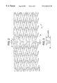
- FIG. 7 is a section view of the graft of FIG. 5 showing the location and angular orientation of opening in the graft;
- FIG. 8 is a sectional view of the graft of FIG. 5 showing a part of the structure of the graft before and after expansion.
- the figures disclose an expandable intraluminal graft, or expandable prosthesis for a body passageway.
- the terms “expandable intraluminal graft” and “expandable prosthesis” are interchangeably used to some extent in describing the present invention, insofar as the apparatus and structures of the present invention may be utilized not only in connection with an expandable intraluminal graft for expanding partially occluded segments of a blood vessel, or body passageway.
- the expandable prostheses may also be used for such purposes as supportive graft placement within blocked vasculature opened by transluminal recanalization, but which are likely to collapse in the absence of an internal support; forming a catheter passage through mediastinal and other veins occluded by inoperable cancers; reinforcement of catheter created intrahepatic communications between portal and hepatic veins in patients suffering from portal hypertension; supportive graft placement of narrowing of the esophagus, the intestine, the ureter, the urethra; and supportive graft reinforcement of reopened and previously obstructed bile ducts.
- body passageway encompasses any duct within the human body, such as those previously described, as well as any vein, artery, or blood vessel within the human vascular system.
- the expandable intraluminal graft as shown in the FIGS. 1, 2 , 3 and 4 generally comprises a tubular shaped member 10 having first end 12 and second end 14 and a wall surface 16 disposed between the first and second ends.
- the wall surface is formed by a plurality of intersecting elongated members 18 with at least some of the elongated members intersecting with one another intermediate the first and second ends of the tubular shaped member.
- the tubular shaped member has a first diameter which permits intraluminal delivery of the tubular shaped member into a body passageway having a lumen.
- FIG. 4 shows a perspective view of the tubular shaped member 10 which has a second, expanded diameter, which second diameter is variable in size.
- the elongated members 18 which form wall surface of the tubular shaped member may be any suitable material which is compatible with the human body and the bodily fluids with which the graft, or prosthesis, may come into contact.
- the elongated members are made of a material or include a material that is readily visible in vivo under fluoroscopic view.
- the elongated members also are made of a material which has the requisite strength and elasticity characteristics to permit the tubular shaped member to be expanded from its original tubular form, to its expanded tubular form, and to further to permit the tubular shaped member to retain its expanded configuration with the enlarged diameter.
- Suitable materials for the fabrication the of tubular shaped structure of include tantalum, stainless steel, titanium or any suitable plastic material having the requisite characteristics previously described.
- the elongated members 18 are small diameter, about 0.005 inches, wires or bars. It should of course be understood that each elongated member could have any cross-sectional configurations, such as triangular, square, rectangular, hexagonal, etc. Further, it is preferable that the plurality of elongated members are fixedly secured to one another with a “U” shaped member 17 where the elongated members 18 join with one another. Preferably, the elongated members are formed by etching a single tubular piece of material so that each individual intersection need not be welded.
- a tubular shaped member is initially a thin-walled metal tube, and the openings between the intersecting bars are formed by a conventional etching process, such as electromechanical or laser etching, whereby the resultant structure is a tubular shaped member having a plurality of intersecting elongated members as shown in FIGS. 1 and 2.
- etching process such as electromechanical or laser etching
- tubular shaped structure of is made of stainless steel.
- the particular design of the pattern is shown in the FIGS. 1 and 2.
- the openings between the intersecting bars are preferably parallelogram in shape.
- the openings are positioned to form a pattern as shown in the FIG. 4 .
- this parallelogram pattern allows the tubular shaped members to be expanded without the members having a reduction in length in the longitudinal direction. Since a parallelogram is a four sided figure with opposite sides parallel. As the angle of the parallelogram changes, the sides that are elongated with the longitudinal axis of structure of member 18 will remain the same.
- the surface of the tubular member is formed by pluralities of parallelograms.
- FIG. 1 is the improved arrangement for connecting two tubular members 18 by at least one “U” shaped member 17 together to increase the flexibility of the graft.
- the connector is shown to be a “U” shaped member 17 that connects two ends of the tubular members 18 together.
- pluralities of “U” shaped members 17 are used to connect a set of two adjacently positioned ends of one tubular member to a corresponding set of adjacently positioned ends in the other tubular member.
- This configuration allows at least two tubular members that are connected together by at least one set of circularly distributed “U” shaped connector that allows transverse bending and flexibility invariant to the plane of bending.
- a graft 19 includes two sections 34 , 36 .
- graft 19 may include more than two sections.
- the two sections 34 , 36 are connected together by a connector 28 .
- connector 28 is arcuate in shape and more preferably is “U” shaped.
- sections 34 , 36 are substantially symmetrical to one another and preferably have substantially identical dimensions.
- Each section includes a plurality of slots 20 , 26 . Slots 20 , 26 are preferably equal in length and width.
- the series of slots 20 are arranged substantially parallel to one another.
- the series of slots 26 are also arranged substantially parallel to one another.
- Slots 20 and 26 are positioned relative to one another to form an angle between 0-90° when the graft is in the unexpanded position as shown in FIG. 5 .
- the slot arrangement between ends 22 and 23 of graft 19 allow the graft, when expanded radially, to retain its originally pre-expanded length.
- the configuration of the slots 20 , 26 in the pre-expanded and post-expanded position is shown in FIG. 8 .
- the formation of slots 20 , 26 by use of a laser is shown in FIG. 7 . However, the slots can be formed by other means.
- the configuration of connectors 28 is shown in FIG. 6 .
Abstract
Description
Claims (64)
Priority Applications (6)
| Application Number | Priority Date | Filing Date | Title |
|---|---|---|---|
| US09/273,736 US6436133B1 (en) | 1998-04-15 | 1999-03-22 | Expandable graft |
| US09/363,052 US6206916B1 (en) | 1998-04-15 | 1999-07-29 | Coated intraluminal graft |
| US10/039,816 US20020099438A1 (en) | 1998-04-15 | 2001-10-26 | Irradiated stent coating |
| US10/209,591 US20030040790A1 (en) | 1998-04-15 | 2002-07-31 | Stent coating |
| US10/810,356 US8603158B2 (en) | 1998-04-15 | 2004-03-26 | Irradiated stent coating |
| US12/267,651 US8114152B2 (en) | 1998-04-15 | 2008-11-10 | Stent coating |
Applications Claiming Priority (2)
| Application Number | Priority Date | Filing Date | Title |
|---|---|---|---|
| US8182498P | 1998-04-15 | 1998-04-15 | |
| US09/273,736 US6436133B1 (en) | 1998-04-15 | 1999-03-22 | Expandable graft |
Related Parent Applications (1)
| Application Number | Title | Priority Date | Filing Date |
|---|---|---|---|
| US09/363,052 Continuation-In-Part US6206916B1 (en) | 1998-04-15 | 1999-07-29 | Coated intraluminal graft |
Related Child Applications (2)
| Application Number | Title | Priority Date | Filing Date |
|---|---|---|---|
| US09/363,052 Continuation-In-Part US6206916B1 (en) | 1998-04-15 | 1999-07-29 | Coated intraluminal graft |
| US77107301A Continuation-In-Part | 1998-04-15 | 2001-01-29 |
Publications (1)
| Publication Number | Publication Date |
|---|---|
| US6436133B1 true US6436133B1 (en) | 2002-08-20 |
Family
ID=26766008
Family Applications (1)
| Application Number | Title | Priority Date | Filing Date |
|---|---|---|---|
| US09/273,736 Expired - Lifetime US6436133B1 (en) | 1998-04-15 | 1999-03-22 | Expandable graft |
Country Status (1)
| Country | Link |
|---|---|
| US (1) | US6436133B1 (en) |
Cited By (89)
| Publication number | Priority date | Publication date | Assignee | Title |
|---|---|---|---|---|
| WO2003037398A2 (en) * | 2001-10-26 | 2003-05-08 | Icon Technologies Llc. | Improved stent coating |
| US20040127973A1 (en) * | 2002-11-05 | 2004-07-01 | Mangiardi Eric K. | Removable biliary stent |
| US20040181277A1 (en) * | 1998-04-15 | 2004-09-16 | Icon Interventional Systems, Inc., An Ohio Corporation | Irradiated stent coating |
| US20050038472A1 (en) * | 2002-07-31 | 2005-02-17 | Icon Interventional Systems, Inc. | Sutures and surgical staples for anastamoses, wound closures, and surgical closures |
| WO2005032413A3 (en) * | 2003-09-30 | 2005-06-09 | Alveolus Inc | Active stent |
| US20050159802A1 (en) * | 2004-01-15 | 2005-07-21 | Icon Interventional Systems, Inc., An Ohio Corporation | Method for verifying position on an angioplasty balloon |
| US20050165476A1 (en) * | 2004-01-23 | 2005-07-28 | Furst Joseph G. | Vascular grafts with amphiphilic block copolymer coatings |
| US20050171596A1 (en) * | 2004-02-03 | 2005-08-04 | Furst Joseph G. | Stents with amphiphilic copolymer coatings |
| WO2006096263A2 (en) | 2005-03-03 | 2006-09-14 | Icon Medical Corp. | Process for forming an improved metal alloy stent |
| US20070043381A1 (en) * | 2005-08-19 | 2007-02-22 | Icon Medical Corp. | Medical device deployment instrument |
| WO2007087069A2 (en) | 2006-01-20 | 2007-08-02 | Icon Medical Corp. | Biodegradable device |
| US20080103367A1 (en) * | 2006-10-13 | 2008-05-01 | Burba Thomas A | Eye positioner |
| WO2008112458A2 (en) | 2007-03-09 | 2008-09-18 | Icon Medical Corp | Bioabsorbable coatings for medical devices |
| US20080234794A1 (en) * | 2007-03-23 | 2008-09-25 | Dirk Tenne | Implantable stents having a plurality of varying parallelogrammic cells and methods for manufacturing the same |
| AU2003284180B2 (en) * | 2002-11-05 | 2009-01-08 | Merit Medical Systems, Inc. | Stent with geometry determinated functionality and method of making the same |
| US7547321B2 (en) * | 2001-07-26 | 2009-06-16 | Alveolus Inc. | Removable stent and method of using the same |
| US7766954B2 (en) | 2001-12-20 | 2010-08-03 | Trivascular2, Inc. | Advanced endovascular graft |
| US7803178B2 (en) | 2004-01-30 | 2010-09-28 | Trivascular, Inc. | Inflatable porous implants and methods for drug delivery |
| US7887579B2 (en) | 2004-09-29 | 2011-02-15 | Merit Medical Systems, Inc. | Active stent |
| US7931683B2 (en) | 2007-07-27 | 2011-04-26 | Boston Scientific Scimed, Inc. | Articles having ceramic coated surfaces |
| US7938855B2 (en) | 2007-11-02 | 2011-05-10 | Boston Scientific Scimed, Inc. | Deformable underlayer for stent |
| US7942926B2 (en) | 2007-07-11 | 2011-05-17 | Boston Scientific Scimed, Inc. | Endoprosthesis coating |
| US7959671B2 (en) | 2002-11-05 | 2011-06-14 | Merit Medical Systems, Inc. | Differential covering and coating methods |
| US7967855B2 (en) | 1998-07-27 | 2011-06-28 | Icon Interventional Systems, Inc. | Coated medical device |
| US7976915B2 (en) | 2007-05-23 | 2011-07-12 | Boston Scientific Scimed, Inc. | Endoprosthesis with select ceramic morphology |
| US7981150B2 (en) | 2006-11-09 | 2011-07-19 | Boston Scientific Scimed, Inc. | Endoprosthesis with coatings |
| US7985252B2 (en) | 2008-07-30 | 2011-07-26 | Boston Scientific Scimed, Inc. | Bioerodible endoprosthesis |
| US7998192B2 (en) | 2008-05-09 | 2011-08-16 | Boston Scientific Scimed, Inc. | Endoprostheses |
| US8002823B2 (en) | 2007-07-11 | 2011-08-23 | Boston Scientific Scimed, Inc. | Endoprosthesis coating |
| US8002821B2 (en) | 2006-09-18 | 2011-08-23 | Boston Scientific Scimed, Inc. | Bioerodible metallic ENDOPROSTHESES |
| US20110214785A1 (en) * | 2010-03-04 | 2011-09-08 | Icon Medical Corp. | method for forming a tubular medical device |
| US8029554B2 (en) | 2007-11-02 | 2011-10-04 | Boston Scientific Scimed, Inc. | Stent with embedded material |
| US8048150B2 (en) | 2006-04-12 | 2011-11-01 | Boston Scientific Scimed, Inc. | Endoprosthesis having a fiber meshwork disposed thereon |
| US8052744B2 (en) | 2006-09-15 | 2011-11-08 | Boston Scientific Scimed, Inc. | Medical devices and methods of making the same |
| US8052743B2 (en) | 2006-08-02 | 2011-11-08 | Boston Scientific Scimed, Inc. | Endoprosthesis with three-dimensional disintegration control |
| US8052745B2 (en) | 2007-09-13 | 2011-11-08 | Boston Scientific Scimed, Inc. | Endoprosthesis |
| US8057534B2 (en) | 2006-09-15 | 2011-11-15 | Boston Scientific Scimed, Inc. | Bioerodible endoprostheses and methods of making the same |
| US8067054B2 (en) | 2007-04-05 | 2011-11-29 | Boston Scientific Scimed, Inc. | Stents with ceramic drug reservoir layer and methods of making and using the same |
| US8066755B2 (en) | 2007-09-26 | 2011-11-29 | Trivascular, Inc. | System and method of pivoted stent deployment |
| US8066763B2 (en) | 1998-04-11 | 2011-11-29 | Boston Scientific Scimed, Inc. | Drug-releasing stent with ceramic-containing layer |
| US8070797B2 (en) | 2007-03-01 | 2011-12-06 | Boston Scientific Scimed, Inc. | Medical device with a porous surface for delivery of a therapeutic agent |
| US8070796B2 (en) | 1998-07-27 | 2011-12-06 | Icon Interventional Systems, Inc. | Thrombosis inhibiting graft |
| US8071156B2 (en) | 2009-03-04 | 2011-12-06 | Boston Scientific Scimed, Inc. | Endoprostheses |
| US8080055B2 (en) | 2006-12-28 | 2011-12-20 | Boston Scientific Scimed, Inc. | Bioerodible endoprostheses and methods of making the same |
| US8083789B2 (en) | 2007-11-16 | 2011-12-27 | Trivascular, Inc. | Securement assembly and method for expandable endovascular device |
| US8089029B2 (en) | 2006-02-01 | 2012-01-03 | Boston Scientific Scimed, Inc. | Bioabsorbable metal medical device and method of manufacture |
| US8100963B2 (en) | 2001-10-26 | 2012-01-24 | Icon Medical Corp. | Biodegradable device |
| US8128689B2 (en) | 2006-09-15 | 2012-03-06 | Boston Scientific Scimed, Inc. | Bioerodible endoprosthesis with biostable inorganic layers |
| US8187620B2 (en) | 2006-03-27 | 2012-05-29 | Boston Scientific Scimed, Inc. | Medical devices comprising a porous metal oxide or metal material and a polymer coating for delivering therapeutic agents |
| US8206436B2 (en) | 2002-11-05 | 2012-06-26 | Merit Medical Systems, Inc. | Coated stent with geometry determinated functionality and method of making the same |
| US8216632B2 (en) | 2007-11-02 | 2012-07-10 | Boston Scientific Scimed, Inc. | Endoprosthesis coating |
| US8221822B2 (en) | 2007-07-31 | 2012-07-17 | Boston Scientific Scimed, Inc. | Medical device coating by laser cladding |
| US8226701B2 (en) | 2007-09-26 | 2012-07-24 | Trivascular, Inc. | Stent and delivery system for deployment thereof |
| US8231980B2 (en) | 2008-12-03 | 2012-07-31 | Boston Scientific Scimed, Inc. | Medical implants including iridium oxide |
| US8236046B2 (en) | 2008-06-10 | 2012-08-07 | Boston Scientific Scimed, Inc. | Bioerodible endoprosthesis |
| US8267992B2 (en) | 2009-03-02 | 2012-09-18 | Boston Scientific Scimed, Inc. | Self-buffering medical implants |
| US8287937B2 (en) | 2009-04-24 | 2012-10-16 | Boston Scientific Scimed, Inc. | Endoprosthese |
| US8303643B2 (en) | 2001-06-27 | 2012-11-06 | Remon Medical Technologies Ltd. | Method and device for electrochemical formation of therapeutic species in vivo |
| US8323333B2 (en) | 2005-03-03 | 2012-12-04 | Icon Medical Corp. | Fragile structure protective coating |
| US8328861B2 (en) | 2007-11-16 | 2012-12-11 | Trivascular, Inc. | Delivery system and method for bifurcated graft |
| US8353949B2 (en) | 2006-09-14 | 2013-01-15 | Boston Scientific Scimed, Inc. | Medical devices with drug-eluting coating |
| US8361136B2 (en) | 1998-02-09 | 2013-01-29 | Trivascular, Inc. | Endovascular graft |
| US8382824B2 (en) | 2008-10-03 | 2013-02-26 | Boston Scientific Scimed, Inc. | Medical implant having NANO-crystal grains with barrier layers of metal nitrides or fluorides |
| US8431149B2 (en) | 2007-03-01 | 2013-04-30 | Boston Scientific Scimed, Inc. | Coated medical devices for abluminal drug delivery |
| US8449603B2 (en) | 2008-06-18 | 2013-05-28 | Boston Scientific Scimed, Inc. | Endoprosthesis coating |
| US8574615B2 (en) | 2006-03-24 | 2013-11-05 | Boston Scientific Scimed, Inc. | Medical devices having nanoporous coatings for controlled therapeutic agent delivery |
| US8663309B2 (en) | 2007-09-26 | 2014-03-04 | Trivascular, Inc. | Asymmetric stent apparatus and method |
| US8668732B2 (en) | 2010-03-23 | 2014-03-11 | Boston Scientific Scimed, Inc. | Surface treated bioerodible metal endoprostheses |
| US8771343B2 (en) | 2006-06-29 | 2014-07-08 | Boston Scientific Scimed, Inc. | Medical devices with selective titanium oxide coatings |
| US8769794B2 (en) | 2006-09-21 | 2014-07-08 | Mico Innovations, Llc | Specially configured and surface modified medical device with certain design features that utilize the intrinsic properties of tungsten, zirconium, tantalum and/or niobium |
| US8808618B2 (en) | 2005-03-03 | 2014-08-19 | Icon Medical Corp. | Process for forming an improved metal alloy stent |
| US8808726B2 (en) | 2006-09-15 | 2014-08-19 | Boston Scientific Scimed. Inc. | Bioerodible endoprostheses and methods of making the same |
| US8815273B2 (en) | 2007-07-27 | 2014-08-26 | Boston Scientific Scimed, Inc. | Drug eluting medical devices having porous layers |
| US8815275B2 (en) | 2006-06-28 | 2014-08-26 | Boston Scientific Scimed, Inc. | Coatings for medical devices comprising a therapeutic agent and a metallic material |
| US8840660B2 (en) | 2006-01-05 | 2014-09-23 | Boston Scientific Scimed, Inc. | Bioerodible endoprostheses and methods of making the same |
| US8900292B2 (en) | 2007-08-03 | 2014-12-02 | Boston Scientific Scimed, Inc. | Coating for medical device having increased surface area |
| US8920491B2 (en) | 2008-04-22 | 2014-12-30 | Boston Scientific Scimed, Inc. | Medical devices having a coating of inorganic material |
| US8932346B2 (en) | 2008-04-24 | 2015-01-13 | Boston Scientific Scimed, Inc. | Medical devices having inorganic particle layers |
| US8992595B2 (en) | 2012-04-04 | 2015-03-31 | Trivascular, Inc. | Durable stent graft with tapered struts and stable delivery methods and devices |
| US9107899B2 (en) | 2005-03-03 | 2015-08-18 | Icon Medical Corporation | Metal alloys for medical devices |
| US9284409B2 (en) | 2007-07-19 | 2016-03-15 | Boston Scientific Scimed, Inc. | Endoprosthesis having a non-fouling surface |
| US9498363B2 (en) | 2012-04-06 | 2016-11-22 | Trivascular, Inc. | Delivery catheter for endovascular device |
| KR20180011421A (en) * | 2016-07-22 | 2018-02-01 | 가천대학교 산학협력단 | Bio-scaffold and bioreactor for artificial trachea |
| KR20180011900A (en) * | 2016-07-25 | 2018-02-05 | 가천대학교 산학협력단 | Bioreactor for artificial trachea |
| US10159557B2 (en) | 2007-10-04 | 2018-12-25 | Trivascular, Inc. | Modular vascular graft for low profile percutaneous delivery |
| EP3417833A1 (en) * | 2017-06-19 | 2018-12-26 | Cook Medical Technologies LLC | Intraluminal support device with end cell geometry |
| US11766506B2 (en) | 2016-03-04 | 2023-09-26 | Mirus Llc | Stent device for spinal fusion |
| US11779685B2 (en) | 2014-06-24 | 2023-10-10 | Mirus Llc | Metal alloys for medical devices |
| CN117224297A (en) * | 2023-11-13 | 2023-12-15 | 太原理工大学 | Lower limb artery stent with reverse combined structure |
Citations (19)
| Publication number | Priority date | Publication date | Assignee | Title |
|---|---|---|---|---|
| US4733665A (en) | 1985-11-07 | 1988-03-29 | Expandable Grafts Partnership | Expandable intraluminal graft, and method and apparatus for implanting an expandable intraluminal graft |
| EP0433011A1 (en) * | 1989-12-11 | 1991-06-19 | Robert E. Fischell | Intra-arterial stent with the capability to inhibit intimal hyperplasia |
| US5102417A (en) | 1985-11-07 | 1992-04-07 | Expandable Grafts Partnership | Expandable intraluminal graft, and method and apparatus for implanting an expandable intraluminal graft |
| US5195984A (en) | 1988-10-04 | 1993-03-23 | Expandable Grafts Partnership | Expandable intraluminal graft |
| US5316023A (en) | 1992-01-08 | 1994-05-31 | Expandable Grafts Partnership | Method for bilateral intra-aortic bypass |
| US5725572A (en) * | 1994-04-25 | 1998-03-10 | Advanced Cardiovascular Systems, Inc. | Radiopaque stent |
| US5735871A (en) * | 1994-12-09 | 1998-04-07 | Sgro; Jean-Claude | Self-expanding endoprosthesis |
| EP0836839A2 (en) | 1996-10-21 | 1998-04-22 | InFlow Dynamics SA | Improved vascular and endoluminal stents |
| US5755781A (en) * | 1996-08-06 | 1998-05-26 | Iowa-India Investments Company Limited | Embodiments of multiple interconnected stents |
| US5853419A (en) * | 1997-03-17 | 1998-12-29 | Surface Genesis, Inc. | Stent |
| US5861027A (en) * | 1996-04-10 | 1999-01-19 | Variomed Ag | Stent for the transluminal implantation in hollow organs |
| US5879370A (en) * | 1994-02-25 | 1999-03-09 | Fischell; Robert E. | Stent having a multiplicity of undulating longitudinals |
| US5911732A (en) * | 1997-03-10 | 1999-06-15 | Johnson & Johnson Interventional Systems, Co. | Articulated expandable intraluminal stent |
| US5964798A (en) * | 1997-12-16 | 1999-10-12 | Cardiovasc, Inc. | Stent having high radial strength |
| US5968091A (en) * | 1996-03-26 | 1999-10-19 | Corvita Corp. | Stents and stent grafts having enhanced hoop strength and methods of making the same |
| WO1999056663A2 (en) | 1998-05-05 | 1999-11-11 | Scimed Life Systems, Inc. | Stent with smooth ends |
| US6007573A (en) * | 1996-09-18 | 1999-12-28 | Microtherapeutics, Inc. | Intracranial stent and method of use |
| US6059810A (en) * | 1995-05-10 | 2000-05-09 | Scimed Life Systems, Inc. | Endovascular stent and method |
| US6200337B1 (en) * | 1996-03-10 | 2001-03-13 | Terumo Kabushiki Kaisha | Implanting stent |
-
1999
- 1999-03-22 US US09/273,736 patent/US6436133B1/en not_active Expired - Lifetime
Patent Citations (26)
| Publication number | Priority date | Publication date | Assignee | Title |
|---|---|---|---|---|
| US4733665A (en) | 1985-11-07 | 1988-03-29 | Expandable Grafts Partnership | Expandable intraluminal graft, and method and apparatus for implanting an expandable intraluminal graft |
| US4776337A (en) | 1985-11-07 | 1988-10-11 | Expandable Grafts Partnership | Expandable intraluminal graft, and method and apparatus for implanting an expandable intraluminal graft |
| US4776337B1 (en) | 1985-11-07 | 2000-12-05 | Cordis Corp | Expandable intraluminal graft and method and apparatus for implanting an expandable intraluminal graft |
| US4739762B1 (en) | 1985-11-07 | 1998-10-27 | Expandable Grafts Partnership | Expandable intraluminal graft and method and apparatus for implanting an expandable intraluminal graft |
| US5102417A (en) | 1985-11-07 | 1992-04-07 | Expandable Grafts Partnership | Expandable intraluminal graft, and method and apparatus for implanting an expandable intraluminal graft |
| US4739762A (en) | 1985-11-07 | 1988-04-26 | Expandable Grafts Partnership | Expandable intraluminal graft, and method and apparatus for implanting an expandable intraluminal graft |
| US4733665B1 (en) | 1985-11-07 | 1994-01-11 | Expandable Grafts Partnership | Expandable intraluminal graft,and method and apparatus for implanting an expandable intraluminal graft |
| US4733665C2 (en) | 1985-11-07 | 2002-01-29 | Expandable Grafts Partnership | Expandable intraluminal graft and method and apparatus for implanting an expandable intraluminal graft |
| US5195984A (en) | 1988-10-04 | 1993-03-23 | Expandable Grafts Partnership | Expandable intraluminal graft |
| EP0433011A1 (en) * | 1989-12-11 | 1991-06-19 | Robert E. Fischell | Intra-arterial stent with the capability to inhibit intimal hyperplasia |
| US5316023A (en) | 1992-01-08 | 1994-05-31 | Expandable Grafts Partnership | Method for bilateral intra-aortic bypass |
| US5571170A (en) | 1992-01-08 | 1996-11-05 | Expandable Grafts Partnership | Method and apparatus for bilateral intra-aortic bypass |
| US5879370A (en) * | 1994-02-25 | 1999-03-09 | Fischell; Robert E. | Stent having a multiplicity of undulating longitudinals |
| US5725572A (en) * | 1994-04-25 | 1998-03-10 | Advanced Cardiovascular Systems, Inc. | Radiopaque stent |
| US5735871A (en) * | 1994-12-09 | 1998-04-07 | Sgro; Jean-Claude | Self-expanding endoprosthesis |
| US6059810A (en) * | 1995-05-10 | 2000-05-09 | Scimed Life Systems, Inc. | Endovascular stent and method |
| US6200337B1 (en) * | 1996-03-10 | 2001-03-13 | Terumo Kabushiki Kaisha | Implanting stent |
| US5968091A (en) * | 1996-03-26 | 1999-10-19 | Corvita Corp. | Stents and stent grafts having enhanced hoop strength and methods of making the same |
| US5861027A (en) * | 1996-04-10 | 1999-01-19 | Variomed Ag | Stent for the transluminal implantation in hollow organs |
| US5755781A (en) * | 1996-08-06 | 1998-05-26 | Iowa-India Investments Company Limited | Embodiments of multiple interconnected stents |
| US6007573A (en) * | 1996-09-18 | 1999-12-28 | Microtherapeutics, Inc. | Intracranial stent and method of use |
| EP0836839A2 (en) | 1996-10-21 | 1998-04-22 | InFlow Dynamics SA | Improved vascular and endoluminal stents |
| US5911732A (en) * | 1997-03-10 | 1999-06-15 | Johnson & Johnson Interventional Systems, Co. | Articulated expandable intraluminal stent |
| US5853419A (en) * | 1997-03-17 | 1998-12-29 | Surface Genesis, Inc. | Stent |
| US5964798A (en) * | 1997-12-16 | 1999-10-12 | Cardiovasc, Inc. | Stent having high radial strength |
| WO1999056663A2 (en) | 1998-05-05 | 1999-11-11 | Scimed Life Systems, Inc. | Stent with smooth ends |
Non-Patent Citations (2)
| Title |
|---|
| "Progress in Cardiovascular Diseases" vol. XXXIX, No. 2, Sep./Oct. 1996. |
| USCI brochure entitled "PE Plus Peripheral Balloon Dilatation Catheter" Aug. 1985. |
Cited By (111)
| Publication number | Priority date | Publication date | Assignee | Title |
|---|---|---|---|---|
| US10548750B2 (en) | 1998-02-09 | 2020-02-04 | Trivascular, Inc. | Endovascular graft |
| US9867727B2 (en) | 1998-02-09 | 2018-01-16 | Trivascular, Inc. | Endovascular graft |
| US8801769B2 (en) | 1998-02-09 | 2014-08-12 | Trivascular, Inc. | Endovascular graft |
| US8361136B2 (en) | 1998-02-09 | 2013-01-29 | Trivascular, Inc. | Endovascular graft |
| US8066763B2 (en) | 1998-04-11 | 2011-11-29 | Boston Scientific Scimed, Inc. | Drug-releasing stent with ceramic-containing layer |
| US8603158B2 (en) | 1998-04-15 | 2013-12-10 | Icon Interventional Systems, Inc | Irradiated stent coating |
| US20040181277A1 (en) * | 1998-04-15 | 2004-09-16 | Icon Interventional Systems, Inc., An Ohio Corporation | Irradiated stent coating |
| US8114152B2 (en) | 1998-04-15 | 2012-02-14 | Icon Interventional Systems, Inc. | Stent coating |
| US7967855B2 (en) | 1998-07-27 | 2011-06-28 | Icon Interventional Systems, Inc. | Coated medical device |
| US8070796B2 (en) | 1998-07-27 | 2011-12-06 | Icon Interventional Systems, Inc. | Thrombosis inhibiting graft |
| US8303643B2 (en) | 2001-06-27 | 2012-11-06 | Remon Medical Technologies Ltd. | Method and device for electrochemical formation of therapeutic species in vivo |
| US7547321B2 (en) * | 2001-07-26 | 2009-06-16 | Alveolus Inc. | Removable stent and method of using the same |
| WO2003037398A2 (en) * | 2001-10-26 | 2003-05-08 | Icon Technologies Llc. | Improved stent coating |
| WO2003037398A3 (en) * | 2001-10-26 | 2003-11-13 | Icon Technologies Llc | Improved stent coating |
| US8100963B2 (en) | 2001-10-26 | 2012-01-24 | Icon Medical Corp. | Biodegradable device |
| US8740973B2 (en) | 2001-10-26 | 2014-06-03 | Icon Medical Corp. | Polymer biodegradable medical device |
| US7766954B2 (en) | 2001-12-20 | 2010-08-03 | Trivascular2, Inc. | Advanced endovascular graft |
| US8016881B2 (en) | 2002-07-31 | 2011-09-13 | Icon Interventional Systems, Inc. | Sutures and surgical staples for anastamoses, wound closures, and surgical closures |
| US20050038472A1 (en) * | 2002-07-31 | 2005-02-17 | Icon Interventional Systems, Inc. | Sutures and surgical staples for anastamoses, wound closures, and surgical closures |
| US20040127973A1 (en) * | 2002-11-05 | 2004-07-01 | Mangiardi Eric K. | Removable biliary stent |
| AU2003284180B2 (en) * | 2002-11-05 | 2009-01-08 | Merit Medical Systems, Inc. | Stent with geometry determinated functionality and method of making the same |
| US7875068B2 (en) | 2002-11-05 | 2011-01-25 | Merit Medical Systems, Inc. | Removable biliary stent |
| US8206436B2 (en) | 2002-11-05 | 2012-06-26 | Merit Medical Systems, Inc. | Coated stent with geometry determinated functionality and method of making the same |
| US7959671B2 (en) | 2002-11-05 | 2011-06-14 | Merit Medical Systems, Inc. | Differential covering and coating methods |
| WO2005032413A3 (en) * | 2003-09-30 | 2005-06-09 | Alveolus Inc | Active stent |
| US7945409B2 (en) | 2004-01-15 | 2011-05-17 | Icon Interventional Systems, Inc. | Method for verifying position on an angioplasty balloon |
| US20050159802A1 (en) * | 2004-01-15 | 2005-07-21 | Icon Interventional Systems, Inc., An Ohio Corporation | Method for verifying position on an angioplasty balloon |
| US20050165476A1 (en) * | 2004-01-23 | 2005-07-28 | Furst Joseph G. | Vascular grafts with amphiphilic block copolymer coatings |
| US7211108B2 (en) | 2004-01-23 | 2007-05-01 | Icon Medical Corp. | Vascular grafts with amphiphilic block copolymer coatings |
| US8267989B2 (en) | 2004-01-30 | 2012-09-18 | Trivascular, Inc. | Inflatable porous implants and methods for drug delivery |
| US7803178B2 (en) | 2004-01-30 | 2010-09-28 | Trivascular, Inc. | Inflatable porous implants and methods for drug delivery |
| US20050171596A1 (en) * | 2004-02-03 | 2005-08-04 | Furst Joseph G. | Stents with amphiphilic copolymer coatings |
| US7887579B2 (en) | 2004-09-29 | 2011-02-15 | Merit Medical Systems, Inc. | Active stent |
| US8323333B2 (en) | 2005-03-03 | 2012-12-04 | Icon Medical Corp. | Fragile structure protective coating |
| WO2006096251A2 (en) | 2005-03-03 | 2006-09-14 | Icon Medical Corp. | Improved metal alloys for medical device |
| WO2006096263A2 (en) | 2005-03-03 | 2006-09-14 | Icon Medical Corp. | Process for forming an improved metal alloy stent |
| US8808618B2 (en) | 2005-03-03 | 2014-08-19 | Icon Medical Corp. | Process for forming an improved metal alloy stent |
| US9107899B2 (en) | 2005-03-03 | 2015-08-18 | Icon Medical Corporation | Metal alloys for medical devices |
| US20070043381A1 (en) * | 2005-08-19 | 2007-02-22 | Icon Medical Corp. | Medical device deployment instrument |
| US8840660B2 (en) | 2006-01-05 | 2014-09-23 | Boston Scientific Scimed, Inc. | Bioerodible endoprostheses and methods of making the same |
| WO2007087069A2 (en) | 2006-01-20 | 2007-08-02 | Icon Medical Corp. | Biodegradable device |
| US8089029B2 (en) | 2006-02-01 | 2012-01-03 | Boston Scientific Scimed, Inc. | Bioabsorbable metal medical device and method of manufacture |
| US8574615B2 (en) | 2006-03-24 | 2013-11-05 | Boston Scientific Scimed, Inc. | Medical devices having nanoporous coatings for controlled therapeutic agent delivery |
| US8187620B2 (en) | 2006-03-27 | 2012-05-29 | Boston Scientific Scimed, Inc. | Medical devices comprising a porous metal oxide or metal material and a polymer coating for delivering therapeutic agents |
| US8048150B2 (en) | 2006-04-12 | 2011-11-01 | Boston Scientific Scimed, Inc. | Endoprosthesis having a fiber meshwork disposed thereon |
| US8815275B2 (en) | 2006-06-28 | 2014-08-26 | Boston Scientific Scimed, Inc. | Coatings for medical devices comprising a therapeutic agent and a metallic material |
| US8771343B2 (en) | 2006-06-29 | 2014-07-08 | Boston Scientific Scimed, Inc. | Medical devices with selective titanium oxide coatings |
| US8052743B2 (en) | 2006-08-02 | 2011-11-08 | Boston Scientific Scimed, Inc. | Endoprosthesis with three-dimensional disintegration control |
| US8353949B2 (en) | 2006-09-14 | 2013-01-15 | Boston Scientific Scimed, Inc. | Medical devices with drug-eluting coating |
| US8128689B2 (en) | 2006-09-15 | 2012-03-06 | Boston Scientific Scimed, Inc. | Bioerodible endoprosthesis with biostable inorganic layers |
| US8808726B2 (en) | 2006-09-15 | 2014-08-19 | Boston Scientific Scimed. Inc. | Bioerodible endoprostheses and methods of making the same |
| US8052744B2 (en) | 2006-09-15 | 2011-11-08 | Boston Scientific Scimed, Inc. | Medical devices and methods of making the same |
| US8057534B2 (en) | 2006-09-15 | 2011-11-15 | Boston Scientific Scimed, Inc. | Bioerodible endoprostheses and methods of making the same |
| US8002821B2 (en) | 2006-09-18 | 2011-08-23 | Boston Scientific Scimed, Inc. | Bioerodible metallic ENDOPROSTHESES |
| US8769794B2 (en) | 2006-09-21 | 2014-07-08 | Mico Innovations, Llc | Specially configured and surface modified medical device with certain design features that utilize the intrinsic properties of tungsten, zirconium, tantalum and/or niobium |
| US20080103367A1 (en) * | 2006-10-13 | 2008-05-01 | Burba Thomas A | Eye positioner |
| US7927344B2 (en) * | 2006-10-13 | 2011-04-19 | Burba Thomas A | Eye positioner |
| US7981150B2 (en) | 2006-11-09 | 2011-07-19 | Boston Scientific Scimed, Inc. | Endoprosthesis with coatings |
| US8715339B2 (en) | 2006-12-28 | 2014-05-06 | Boston Scientific Scimed, Inc. | Bioerodible endoprostheses and methods of making the same |
| US8080055B2 (en) | 2006-12-28 | 2011-12-20 | Boston Scientific Scimed, Inc. | Bioerodible endoprostheses and methods of making the same |
| US8431149B2 (en) | 2007-03-01 | 2013-04-30 | Boston Scientific Scimed, Inc. | Coated medical devices for abluminal drug delivery |
| US8070797B2 (en) | 2007-03-01 | 2011-12-06 | Boston Scientific Scimed, Inc. | Medical device with a porous surface for delivery of a therapeutic agent |
| WO2008112458A2 (en) | 2007-03-09 | 2008-09-18 | Icon Medical Corp | Bioabsorbable coatings for medical devices |
| US8549722B2 (en) | 2007-03-23 | 2013-10-08 | DePuy Synthes Products, LLC | Methods for manufacturing implantable stents having a plurality of varying parallelogrammic cells |
| US20080234794A1 (en) * | 2007-03-23 | 2008-09-25 | Dirk Tenne | Implantable stents having a plurality of varying parallelogrammic cells and methods for manufacturing the same |
| US8062347B2 (en) | 2007-03-23 | 2011-11-22 | Codman & Shurtleff, Inc. | Implantable stents having a plurality of varying parallelogrammic cells and methods for manufacturing the same |
| US8067054B2 (en) | 2007-04-05 | 2011-11-29 | Boston Scientific Scimed, Inc. | Stents with ceramic drug reservoir layer and methods of making and using the same |
| US7976915B2 (en) | 2007-05-23 | 2011-07-12 | Boston Scientific Scimed, Inc. | Endoprosthesis with select ceramic morphology |
| US8002823B2 (en) | 2007-07-11 | 2011-08-23 | Boston Scientific Scimed, Inc. | Endoprosthesis coating |
| US7942926B2 (en) | 2007-07-11 | 2011-05-17 | Boston Scientific Scimed, Inc. | Endoprosthesis coating |
| US9284409B2 (en) | 2007-07-19 | 2016-03-15 | Boston Scientific Scimed, Inc. | Endoprosthesis having a non-fouling surface |
| US7931683B2 (en) | 2007-07-27 | 2011-04-26 | Boston Scientific Scimed, Inc. | Articles having ceramic coated surfaces |
| US8815273B2 (en) | 2007-07-27 | 2014-08-26 | Boston Scientific Scimed, Inc. | Drug eluting medical devices having porous layers |
| US8221822B2 (en) | 2007-07-31 | 2012-07-17 | Boston Scientific Scimed, Inc. | Medical device coating by laser cladding |
| US8900292B2 (en) | 2007-08-03 | 2014-12-02 | Boston Scientific Scimed, Inc. | Coating for medical device having increased surface area |
| US8052745B2 (en) | 2007-09-13 | 2011-11-08 | Boston Scientific Scimed, Inc. | Endoprosthesis |
| US8226701B2 (en) | 2007-09-26 | 2012-07-24 | Trivascular, Inc. | Stent and delivery system for deployment thereof |
| US8066755B2 (en) | 2007-09-26 | 2011-11-29 | Trivascular, Inc. | System and method of pivoted stent deployment |
| US8663309B2 (en) | 2007-09-26 | 2014-03-04 | Trivascular, Inc. | Asymmetric stent apparatus and method |
| US10682222B2 (en) | 2007-10-04 | 2020-06-16 | Trivascular, Inc. | Modular vascular graft for low profile percutaneous delivery |
| US10159557B2 (en) | 2007-10-04 | 2018-12-25 | Trivascular, Inc. | Modular vascular graft for low profile percutaneous delivery |
| US7938855B2 (en) | 2007-11-02 | 2011-05-10 | Boston Scientific Scimed, Inc. | Deformable underlayer for stent |
| US8216632B2 (en) | 2007-11-02 | 2012-07-10 | Boston Scientific Scimed, Inc. | Endoprosthesis coating |
| US8029554B2 (en) | 2007-11-02 | 2011-10-04 | Boston Scientific Scimed, Inc. | Stent with embedded material |
| US8083789B2 (en) | 2007-11-16 | 2011-12-27 | Trivascular, Inc. | Securement assembly and method for expandable endovascular device |
| US8328861B2 (en) | 2007-11-16 | 2012-12-11 | Trivascular, Inc. | Delivery system and method for bifurcated graft |
| US8920491B2 (en) | 2008-04-22 | 2014-12-30 | Boston Scientific Scimed, Inc. | Medical devices having a coating of inorganic material |
| US8932346B2 (en) | 2008-04-24 | 2015-01-13 | Boston Scientific Scimed, Inc. | Medical devices having inorganic particle layers |
| US7998192B2 (en) | 2008-05-09 | 2011-08-16 | Boston Scientific Scimed, Inc. | Endoprostheses |
| US8236046B2 (en) | 2008-06-10 | 2012-08-07 | Boston Scientific Scimed, Inc. | Bioerodible endoprosthesis |
| US8449603B2 (en) | 2008-06-18 | 2013-05-28 | Boston Scientific Scimed, Inc. | Endoprosthesis coating |
| US7985252B2 (en) | 2008-07-30 | 2011-07-26 | Boston Scientific Scimed, Inc. | Bioerodible endoprosthesis |
| US8382824B2 (en) | 2008-10-03 | 2013-02-26 | Boston Scientific Scimed, Inc. | Medical implant having NANO-crystal grains with barrier layers of metal nitrides or fluorides |
| US8231980B2 (en) | 2008-12-03 | 2012-07-31 | Boston Scientific Scimed, Inc. | Medical implants including iridium oxide |
| US8267992B2 (en) | 2009-03-02 | 2012-09-18 | Boston Scientific Scimed, Inc. | Self-buffering medical implants |
| US8071156B2 (en) | 2009-03-04 | 2011-12-06 | Boston Scientific Scimed, Inc. | Endoprostheses |
| US8287937B2 (en) | 2009-04-24 | 2012-10-16 | Boston Scientific Scimed, Inc. | Endoprosthese |
| US9034245B2 (en) | 2010-03-04 | 2015-05-19 | Icon Medical Corp. | Method for forming a tubular medical device |
| US20110214785A1 (en) * | 2010-03-04 | 2011-09-08 | Icon Medical Corp. | method for forming a tubular medical device |
| US8398916B2 (en) | 2010-03-04 | 2013-03-19 | Icon Medical Corp. | Method for forming a tubular medical device |
| US8668732B2 (en) | 2010-03-23 | 2014-03-11 | Boston Scientific Scimed, Inc. | Surface treated bioerodible metal endoprostheses |
| US8992595B2 (en) | 2012-04-04 | 2015-03-31 | Trivascular, Inc. | Durable stent graft with tapered struts and stable delivery methods and devices |
| US9498363B2 (en) | 2012-04-06 | 2016-11-22 | Trivascular, Inc. | Delivery catheter for endovascular device |
| US11779685B2 (en) | 2014-06-24 | 2023-10-10 | Mirus Llc | Metal alloys for medical devices |
| US11766506B2 (en) | 2016-03-04 | 2023-09-26 | Mirus Llc | Stent device for spinal fusion |
| KR20180011421A (en) * | 2016-07-22 | 2018-02-01 | 가천대학교 산학협력단 | Bio-scaffold and bioreactor for artificial trachea |
| KR20180011900A (en) * | 2016-07-25 | 2018-02-05 | 가천대학교 산학협력단 | Bioreactor for artificial trachea |
| US10517747B2 (en) | 2017-06-19 | 2019-12-31 | Cook Medical Technologies Llc | Cannula cut stent with closed end cell geometry |
| EP3417833A1 (en) * | 2017-06-19 | 2018-12-26 | Cook Medical Technologies LLC | Intraluminal support device with end cell geometry |
| CN117224297A (en) * | 2023-11-13 | 2023-12-15 | 太原理工大学 | Lower limb artery stent with reverse combined structure |
| CN117224297B (en) * | 2023-11-13 | 2024-02-13 | 太原理工大学 | Lower limb artery stent with reverse combined structure |
Similar Documents
| Publication | Publication Date | Title |
|---|---|---|
| US6436133B1 (en) | Expandable graft | |
| US6565600B2 (en) | Articulated expandable intraluminal stent | |
| US6206916B1 (en) | Coated intraluminal graft | |
| EP0221570B2 (en) | Expandable intraluminal graft, and apparatus for implanting an expandable intraluminal graft | |
| US5776183A (en) | Expandable stent | |
| JP4659159B2 (en) | Bifurcated stent and manufacturing method thereof | |
| AU633478B2 (en) | Expandable intraluminal graft, and method and apparatus for implanting an expandable intraluminal graft | |
| US5195984A (en) | Expandable intraluminal graft | |
| EP0890346A1 (en) | Expandable intraluminal endoprosthesis | |
| EP1570807A2 (en) | Intralumenal stent device for use in body lumens of various diameters | |
| US20050182477A1 (en) | Intraluminal stent and graft | |
| JP2000202032A (en) | Expandable intraluminal endoprosthesis | |
| US20080027533A1 (en) | Dedicated bifurcation stent apparatus and method | |
| US20030074051A1 (en) | Flexible stent | |
| AU702684B2 (en) | Connected stent apparatus | |
| EP0806191A1 (en) | Expandable intraluminal graft or stent | |
| WO2002058751A2 (en) | Coated intraluminal graft |
Legal Events
| Date | Code | Title | Description |
|---|---|---|---|
| AS | Assignment |
Owner name: FURST, GARY H., OHIO Free format text: ASSIGNMENT OF ASSIGNORS INTEREST;ASSIGNOR:FURST, JOSEPH G.;REEL/FRAME:009897/0041 Effective date: 19990330 |
|
| STCF | Information on status: patent grant |
Free format text: PATENTED CASE |
|
| AS | Assignment |
Owner name: YADAV, JAY S. AS COLLATERAL AGENT C/O THE CLEVELAN Free format text: SECURITY INTEREST;ASSIGNOR:ICON INTERVENTIONAL SYSTEMS, INC.;REEL/FRAME:013842/0405 Effective date: 20030711 |
|
| AS | Assignment |
Owner name: ICON INTERVENTIONAL SYSTEMS INC., OHIO Free format text: TERMINATION OF PATENT SECURITY INTEREST;ASSIGNOR:YADAV AS COLLATERAL AGENT, JAY S;REEL/FRAME:014824/0589 Effective date: 20040515 |
|
| AS | Assignment |
Owner name: ICON INTERVENTIONAL SYSTEMS, INC., OHIO Free format text: ASSIGNMENT OF ASSIGNORS INTEREST;ASSIGNOR:FURST, GARY;REEL/FRAME:015766/0711 Effective date: 20040903 |
|
| FPAY | Fee payment |
Year of fee payment: 4 |
|
| FPAY | Fee payment |
Year of fee payment: 8 |
|
| FPAY | Fee payment |
Year of fee payment: 12 |
|
| AS | Assignment |
Owner name: MIRUS LLC, GEORGIA Free format text: ASSIGNMENT OF ASSIGNORS INTEREST;ASSIGNOR:ICON INTERVENTIONAL SYSTEMS, INC.;REEL/FRAME:042435/0782 Effective date: 20170516 |