US6360856B1 - Double-tube shock absorber using a hydraulic fluid and a magnetorheological fluid - Google Patents
Double-tube shock absorber using a hydraulic fluid and a magnetorheological fluid Download PDFInfo
- Publication number
- US6360856B1 US6360856B1 US09/755,810 US75581001A US6360856B1 US 6360856 B1 US6360856 B1 US 6360856B1 US 75581001 A US75581001 A US 75581001A US 6360856 B1 US6360856 B1 US 6360856B1
- Authority
- US
- United States
- Prior art keywords
- piston
- shock absorber
- fluid
- working chamber
- double
- Prior art date
- Legal status (The legal status is an assumption and is not a legal conclusion. Google has not performed a legal analysis and makes no representation as to the accuracy of the status listed.)
- Expired - Lifetime
Links
Images


Classifications
-
- F—MECHANICAL ENGINEERING; LIGHTING; HEATING; WEAPONS; BLASTING
- F16—ENGINEERING ELEMENTS AND UNITS; GENERAL MEASURES FOR PRODUCING AND MAINTAINING EFFECTIVE FUNCTIONING OF MACHINES OR INSTALLATIONS; THERMAL INSULATION IN GENERAL
- F16F—SPRINGS; SHOCK-ABSORBERS; MEANS FOR DAMPING VIBRATION
- F16F9/00—Springs, vibration-dampers, shock-absorbers, or similarly-constructed movement-dampers using a fluid or the equivalent as damping medium
- F16F9/06—Springs, vibration-dampers, shock-absorbers, or similarly-constructed movement-dampers using a fluid or the equivalent as damping medium using both gas and liquid
- F16F9/062—Bi-tubular units
-
- F—MECHANICAL ENGINEERING; LIGHTING; HEATING; WEAPONS; BLASTING
- F16—ENGINEERING ELEMENTS AND UNITS; GENERAL MEASURES FOR PRODUCING AND MAINTAINING EFFECTIVE FUNCTIONING OF MACHINES OR INSTALLATIONS; THERMAL INSULATION IN GENERAL
- F16F—SPRINGS; SHOCK-ABSORBERS; MEANS FOR DAMPING VIBRATION
- F16F9/00—Springs, vibration-dampers, shock-absorbers, or similarly-constructed movement-dampers using a fluid or the equivalent as damping medium
- F16F9/32—Details
- F16F9/53—Means for adjusting damping characteristics by varying fluid viscosity, e.g. electromagnetically
- F16F9/535—Magnetorheological [MR] fluid dampers
Definitions
- the present invention relates to a shock absorber for use in a motor vehicle; and, more particularly, to a double-tube shock absorber using a magnetorheological (MR) fluid and a hydraulic fluid.
- MR magnetorheological
- motor vehicles are equipped with a suspension system to improve road-adherence and to provide ride-comfort for occupants.
- the suspension system includes springs and shock absorbers.
- the shock absorbers are disposed in parallel with the springs to damp the vibration of the springs.
- the shock absorbers utilize a fluid flow system incorporating therein either a hydraulic fluid having a constant viscosity or a fluid having a changeable viscosity, e.g., magnetorheological (MR) fluid.
- MR fluid is advantageous in that the viscosity thereof can be controlled with the application of a magnetic field in order to adjust a damping force being exerted on the springs depending on a traveling condition.
- MR fluid is a free-flowing liquid with a viscosity. Exposure to a magnetic field can transform the liquid into a near-solid in milliseconds; and with the removal of the magnetic field, the fluid can be returned to its liquid state just as quickly. The degree of change in the viscosity of the MR fluid is proportional to the magnitude of the applied magnetic field.
- FIGS. 1 and 2 are a cross sectional view illustrating a conventional shock absorber using an MR fluid and an enlarged cross sectional view depicting a piston assembly shown in FIG. 1, respectively, disclosed in U.S. Pat. No. 5,284,330 entitled “MAGNETORHEOLOGICAL FLUID DEVICE” issued on Jan. 11, 1994.
- the shock absorber 10 comprises two principal components: a housing 20 and a piston assembly 30 .
- the housing 20 includes a volume of magnetorheological (MR) fluid.
- the fluid includes carbonyl iron particles suspended in silicone oil.
- the housing 20 is generally of a cylindrical tube with a first closed end 22 .
- a cylindrical sleeve 25 may be affixed to an inner cylinder by any conventional means, e.g., press fit, welding or adhesive to increase the cross-sectional surface area of the housing 20 .
- the cylinder is closed at a second end thereof by an end member 26 .
- a first seal 27 extends about an outer periphery of the end member 26 to prevent fluid leakage between the housing 20 and the end member 26 .
- a second annular seal 28 is housed in a groove in an inner periphery of the end member 26 and seals against a piston rod 32 .
- a scraper 29 can be used to wipe the MR fluid off the surface of piston rod 32 so as to minimize the loss of MR fluid past the second annular seal 28 .
- the housing 20 is provided with a floating piston 21 to separate the MR fluid from a pressurized accumulator 23 .
- the pressurized accumulator 23 is necessary to accommodate a fluid displaced by the piston rod 32 as well as to allow for thermal expansion of the fluid.
- the piston assembly 30 is shown in greater detail in FIG. 2.
- a piston head 34 is spool shaped with an upper outwardly extending flange 36 and a lower outwardly extending flange 38 .
- a coil 40 is wound upon the spool-shaped piston head 34 between the upper flange 36 and the lower flange 38 .
- the piston head 34 is made of a magnetically permeable material, such as low carbon steel.
- Guide rails 42 are attached around an outside of the piston head 34 at particular intervals. As shown in FIGS. 1 and 2, four guide rails 42 are shown spaced uniformly about a periphery of the piston head 34 .
- An electrical connection is made to the coil 40 through the piston rod 32 by lead wires 45 and 47 .
- the first lead wire 45 is connected to a first end of an electrically conductive rod 48 which extends through the piston rod 32 to a Phono-jack connector 46 .
- a center connection of the Phono-jack 46 is connected to a first end 39 of the coil 40 .
- a second end 41 of windings of the coil 40 is attached to a “ground” connection on an outside of the Phono-jack 46 .
- An electrical return path includes the piston rod 32 and the ground lead 47 .
- an object of the present invention to provide a double-tube shock absorber using a magnetorheological fluid and a hydraulic fluid.
- a double-tube shock absorber comprising: an outer cylinder having a first working chamber; an inner cylinder located inside the first working chamber and having a second working chamber, wherein the first and the second working chamber are filled with a hydraulic fluid and a magnetorheological fluid, respectively; a first piston movably inserted into the first working chamber; a second piston having a coil movably inserted into the second working chamber, wherein each of the pistons includes one or more orifices; one or more first piston rods for leading the first piston in a reciprocating motion; and a second piston rod for leading the second piston in a reciprocating motion.
- FIG. 1 is a schematic cross sectional view illustrating a shock absorber using a magnetorheological fluid previously disclosed
- FIG. 2 shows an enlarged cross sectional view illustrating a piston assembly incorporated in the shock absorber shown in FIG. 1;
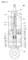
- FIG. 3 offers a schematic cross sectional view depicting a double-tube shock absorber using both a magnetorheological fluid and a hydraulic fluid in accordance with the present invention
- FIG. 4 represents a perspective view portraying piston assembly incorporated in the double-tube shock absorber shown in FIG. 3;
- FIG. 5 provides an enlarged cross sectional view of a portion “A” shown in FIG. 3 .
- An inventive double-tube shock absorber 100 for using in a vehicle, e.g., automobile, comprises a cylinder assembly 110 and a piston assembly 130 , as shown in FIG. 3 .
- the cylinder assembly 110 is provided with an outer cylinder 112 including an outer and an inner surface 121 , 122 , and an inner cylinder 114 having an outer and an inner surface 123 , 124 .
- the outer cylinder 112 incorporates therein a first working chamber 116 .
- the inner cylinder 114 is located inside the first working chamber 116 and incorporates therein a second working chamber 118 .
- the first and the second working chamber 116 , 118 are filled with a hydraulic fluid 126 having a constant low viscosity and a magnetorheological (MR) fluid 128 having a changeable viscosity, respectively.
- the first and the second working chamber 116 , 118 are isolated from each other for preventing the hydraulic fluid 126 and the MR fluid 128 from interflowing therebetween.
- MR magnetorheological
- the piston assembly 130 is provided with a first piston 132 , a second piston 142 , three of first piston rods 152 , a second piston rod 154 and a rod fixture 156 , as shown in FIG. 4 .
- the first piston 132 having an outer and an inner periphery 133 , 134 is movably inserted into the first working chamber 116 with horizontally adjoining its outer periphery 133 to the inner surface 122 of the outer cylinder 112 and its inner periphery 134 to the outer surface 123 of the inner cylinder 114 .
- the first piston 132 includes three of first orifices 135 for providing vertical flowing paths for the hydraulic fluid 126 in the first working chamber 116 .
- the first piston 132 further includes a first and a second sealing member 136 , 137 made of, e.g., Teflon or the like, wherein the first and the second sealing member 136 , 137 are secured on the outer periphery 133 and on the inner periphery 134 of the first piston 132 , respectively, for preventing the hydraulic fluid 126 from flowing along with the outer and the inner periphery 133 , 134 of the first piston 132 , respectively.
- a first and a second sealing member 136 , 137 made of, e.g., Teflon or the like, wherein the first and the second sealing member 136 , 137 are secured on the outer periphery 133 and on the inner periphery 134 of the first piston 132 , respectively, for preventing the hydraulic fluid 126 from flowing along with the outer and the inner periphery 133 , 134 of the first piston 132 , respectively.
- the second piston 142 having an outer periphery 143 is movably inserted into the second working chamber 118 with horizontally adjoining its outer periphery 143 to the inner surface 124 of the inner cylinder 114 .
- the second piston 142 includes three of second orifices 144 for providing vertical flowing paths for the MR fluid 128 in the second working chamber 118 .
- the second piston 142 further includes a third sealing member 145 made of, e.g., Teflon or the like, and secured on the outer periphery 143 for preventing the MR fluid 128 from flowing along with the outer periphery 143 of the second piston 142 .
- first and second orifices 135 , 144 can be formed in the first piston 132 and the second piston 142 , respectively.
- the second piston 142 is structured for forming a magnetic field generator, e.g., solenoid, in such a way that the second piston 142 is shaped as a spool having an upper and a lower flange 146 , 147 , and is made of a magnetic permeable material, e.g., ferrite, low-carbon steel or the like, and further is convolved with a coil 148 at the outer periphery 143 thereof between the upper and the lower flange 146 , 147 . Accordingly, when an electrical current is applied to the coil 148 , a magnetic field is generated around the second piston 142 , which will, in turn, change the viscosity of the MR fluid 128 passing through the second orifices 144 .
- a magnetic field generator e.g., solenoid
- first piston rods 152 for leading the first piston 132 in a reciprocating motion are rigidly joined to the first piston 132 at one end thereof. While the number of the first piston rods 152 is preferably three in the above description, the present invention is not limited thereto. Considering various mechanical factors, e.g., balance, tensile force, compressive force or the like, charged to the first piston rods 152 , one or more first piston rods 152 can be rigidly joined to the first piston 132 .
- the second piston rod 154 for leading the second piston 142 in a reciprocating motion is rigidly joined to the second piston 142 at one end thereof
- the second piston rod 154 includes an interior cavity 158 where electrical connections (not shown) for applying the electric signal to the coil 148 are installed.
- first piston rods 152 and the second piston rod 154 are secured to the rod fixture 156 in such a way that the reciprocating motions of the first piston 132 and the second piston 142 are dependent on and coincident to each other during the operation of the double-tube shock absorber 100 .
- the double-tube shock absorber 100 further comprises a number of first and second sealing parts 160 , 161 , a first and a second floating piston 163 , 164 and a first and a second accumulator 165 , 166 .
- the first and second sealing parts 160 , 161 respectively, prevent the hydraulic fluid 126 and the MR fluid 128 from leaking along with the first piston rods 152 and the second piston rod 154 , respectively.
- the first and the second floating piston 163 , 164 are movably inserted into the outer cylinder 112 and the inner cylinder 114 , respectively.
- Each of the accumulator 165 , 166 is filled with a gas, e.g., nitrogen, wherein the first and the second accumulator 165 , 166 are, respectively, necessary to accommodate the hydraulic and the MR fluid 126 , 128 displaced by the first piston rods 152 and the second piston rod 154 as well as to allow for thermal expansion of the hydraulic and the MR fluid 126 , 128 .
- a gas e.g., nitrogen
- the double-tube shock absorber 100 of the present invention utilizes both the hydraulic fluid 126 in the first chamber 116 and the MR fluid 128 in the second chamber 118 . Accordingly, the double-tube shock absorber 100 can sensitively respond to the impulse applied thereto by using the hydraulic fluid 126 having relatively low viscosity and, at the same time, can modulate the damping force by using the MR fluid 128 having adjustable viscosity in consideration with various factors, e.g., driving conditions, driver's controls and so on. Furthermore, the expensive MR fluid 128 is employed in only the second working chamber 118 of the inner cylinder 114 , thereby reducing the amount of the MR fluid 128 needed and, hence, reducing the manufacturing cost of the double-tube shock absorber 100 .
Abstract
Description
Claims (12)
Priority Applications (1)
| Application Number | Priority Date | Filing Date | Title |
|---|---|---|---|
| US09/755,810 US6360856B1 (en) | 2001-01-05 | 2001-01-05 | Double-tube shock absorber using a hydraulic fluid and a magnetorheological fluid |
Applications Claiming Priority (1)
| Application Number | Priority Date | Filing Date | Title |
|---|---|---|---|
| US09/755,810 US6360856B1 (en) | 2001-01-05 | 2001-01-05 | Double-tube shock absorber using a hydraulic fluid and a magnetorheological fluid |
Publications (1)
| Publication Number | Publication Date |
|---|---|
| US6360856B1 true US6360856B1 (en) | 2002-03-26 |
Family
ID=25040742
Family Applications (1)
| Application Number | Title | Priority Date | Filing Date |
|---|---|---|---|
| US09/755,810 Expired - Lifetime US6360856B1 (en) | 2001-01-05 | 2001-01-05 | Double-tube shock absorber using a hydraulic fluid and a magnetorheological fluid |
Country Status (1)
| Country | Link |
|---|---|
| US (1) | US6360856B1 (en) |
Cited By (19)
| Publication number | Priority date | Publication date | Assignee | Title |
|---|---|---|---|---|
| US20030042088A1 (en) * | 2001-08-31 | 2003-03-06 | Maurer Sohne Gmbh & Co. Kg | Force absorption device |
| US6637556B1 (en) * | 2002-08-05 | 2003-10-28 | Delphi Technologies, Inc. | Magneto-rheological damper with grooved fluid passages |
| US6971491B1 (en) * | 2001-12-31 | 2005-12-06 | The Board Of Regents Of The University And Community College System Of Nevada, On Behalf Of The University Of Nevada, Reno | Magneto-rheological fluid encased in flexible materials for vibration control |
| US20050274454A1 (en) * | 2004-06-09 | 2005-12-15 | Extrand Charles W | Magneto-active adhesive systems |
| KR100676281B1 (en) | 2006-01-06 | 2007-02-01 | 인하대학교 산학협력단 | Method and apparatus for shocker absorber of a car bumper in a electroreholigical/magnetorehological fluid-filled |
| US20070056817A1 (en) * | 2005-09-09 | 2007-03-15 | Michael Ward | Damper |
| CN1312413C (en) * | 2005-01-05 | 2007-04-25 | 湖南大学 | Permanent-magnet adjusting assembled magnetorheological buffer |
| US20080067019A1 (en) * | 2006-09-19 | 2008-03-20 | Delphi Technologies, Inc. | Magnetorheological damper |
| US20100109277A1 (en) * | 2008-11-06 | 2010-05-06 | Furrer Fredrick J | Adjustable Monotube Shock Absorber |
| US20100263971A1 (en) * | 2009-04-16 | 2010-10-21 | Lee Dong-Rak | Damper for continuously variably adjusting damping force |
| CZ303530B6 (en) * | 2011-09-26 | 2012-11-14 | Vysoké ucení technické v Brne | Pressure reservoir for single-shell hydraulic damper |
| US20150041263A1 (en) * | 2012-02-24 | 2015-02-12 | Kayaba Industry Co., Ltd. | Magnetic viscous fluid damper and manufacturing method of coil assembly used therefor |
| CN104595410A (en) * | 2015-01-09 | 2015-05-06 | 宁波大学 | Method for improving sealing property of magnetorheological shock absorber |
| US20150165860A1 (en) * | 2013-12-13 | 2015-06-18 | GM Global Technology Operations LLC | Height adjustable damping device |
| US10099295B2 (en) | 2013-10-24 | 2018-10-16 | Roehm Gmbh | Drill chuck |
| EP3771845A1 (en) | 2019-08-02 | 2021-02-03 | BeijingWest Industries Co. Ltd. | Magnetorheological hydraulic damper with passive damping chamber |
| US11280380B2 (en) | 2019-08-02 | 2022-03-22 | Beijingwest Industries Co., Ltd. | Magnetorheological hydraulic damper with passive damping chamber |
| CN114718977A (en) * | 2022-05-06 | 2022-07-08 | 重庆大学 | Magnetorheological hydro-pneumatic spring |
| US11420297B2 (en) * | 2019-04-24 | 2022-08-23 | Hitachi Astemo, Ltd. | Production method for a cylinder device |
Citations (9)
| Publication number | Priority date | Publication date | Assignee | Title |
|---|---|---|---|---|
| US4896752A (en) * | 1988-02-12 | 1990-01-30 | Trw Inc. | Vehicle strut |
| DE4200977A1 (en) | 1992-01-16 | 1993-07-22 | Montan Hydraulik Gmbh & Co Kg | SHOCK ABSORBER |
| GB2267947A (en) | 1992-06-17 | 1993-12-22 | Gec Alsthom Ltd | Controllable motion-damper |
| US5284330A (en) | 1992-06-18 | 1994-02-08 | Lord Corporation | Magnetorheological fluid devices |
| US5316112A (en) * | 1991-04-20 | 1994-05-31 | Bridgestone Corporation | Restricted passage system in vibration damping device |
| EP0607545A1 (en) | 1992-12-02 | 1994-07-27 | Öhlins Racing Ab | Shock absorber |
| US5366048A (en) * | 1989-08-25 | 1994-11-22 | Bridgestone Corporation | Vibration damping device |
| WO1999027273A2 (en) | 1997-11-25 | 1999-06-03 | Lord Corporation | Adjustable valve and vibration dampers utilizing same |
| US5956951A (en) | 1996-09-20 | 1999-09-28 | Mr Technologies | Adjustable magneto-rheological fluid device |
-
2001
- 2001-01-05 US US09/755,810 patent/US6360856B1/en not_active Expired - Lifetime
Patent Citations (9)
| Publication number | Priority date | Publication date | Assignee | Title |
|---|---|---|---|---|
| US4896752A (en) * | 1988-02-12 | 1990-01-30 | Trw Inc. | Vehicle strut |
| US5366048A (en) * | 1989-08-25 | 1994-11-22 | Bridgestone Corporation | Vibration damping device |
| US5316112A (en) * | 1991-04-20 | 1994-05-31 | Bridgestone Corporation | Restricted passage system in vibration damping device |
| DE4200977A1 (en) | 1992-01-16 | 1993-07-22 | Montan Hydraulik Gmbh & Co Kg | SHOCK ABSORBER |
| GB2267947A (en) | 1992-06-17 | 1993-12-22 | Gec Alsthom Ltd | Controllable motion-damper |
| US5284330A (en) | 1992-06-18 | 1994-02-08 | Lord Corporation | Magnetorheological fluid devices |
| EP0607545A1 (en) | 1992-12-02 | 1994-07-27 | Öhlins Racing Ab | Shock absorber |
| US5956951A (en) | 1996-09-20 | 1999-09-28 | Mr Technologies | Adjustable magneto-rheological fluid device |
| WO1999027273A2 (en) | 1997-11-25 | 1999-06-03 | Lord Corporation | Adjustable valve and vibration dampers utilizing same |
Cited By (23)
| Publication number | Priority date | Publication date | Assignee | Title |
|---|---|---|---|---|
| US20030042088A1 (en) * | 2001-08-31 | 2003-03-06 | Maurer Sohne Gmbh & Co. Kg | Force absorption device |
| US6971491B1 (en) * | 2001-12-31 | 2005-12-06 | The Board Of Regents Of The University And Community College System Of Nevada, On Behalf Of The University Of Nevada, Reno | Magneto-rheological fluid encased in flexible materials for vibration control |
| US6637556B1 (en) * | 2002-08-05 | 2003-10-28 | Delphi Technologies, Inc. | Magneto-rheological damper with grooved fluid passages |
| US20050274454A1 (en) * | 2004-06-09 | 2005-12-15 | Extrand Charles W | Magneto-active adhesive systems |
| CN1312413C (en) * | 2005-01-05 | 2007-04-25 | 湖南大学 | Permanent-magnet adjusting assembled magnetorheological buffer |
| US20070056817A1 (en) * | 2005-09-09 | 2007-03-15 | Michael Ward | Damper |
| KR100676281B1 (en) | 2006-01-06 | 2007-02-01 | 인하대학교 산학협력단 | Method and apparatus for shocker absorber of a car bumper in a electroreholigical/magnetorehological fluid-filled |
| US20080067019A1 (en) * | 2006-09-19 | 2008-03-20 | Delphi Technologies, Inc. | Magnetorheological damper |
| US20100109277A1 (en) * | 2008-11-06 | 2010-05-06 | Furrer Fredrick J | Adjustable Monotube Shock Absorber |
| US8225913B2 (en) * | 2009-04-16 | 2012-07-24 | S & T Daewoo Co. Ltd. | Damper for continuously variably adjusting damping force |
| US20100263971A1 (en) * | 2009-04-16 | 2010-10-21 | Lee Dong-Rak | Damper for continuously variably adjusting damping force |
| CZ303530B6 (en) * | 2011-09-26 | 2012-11-14 | Vysoké ucení technické v Brne | Pressure reservoir for single-shell hydraulic damper |
| US20150041263A1 (en) * | 2012-02-24 | 2015-02-12 | Kayaba Industry Co., Ltd. | Magnetic viscous fluid damper and manufacturing method of coil assembly used therefor |
| US9347514B2 (en) * | 2012-02-24 | 2016-05-24 | Kyb Corporation | Magnetic viscous fluid damper and manufacturing method of coil assembly used therefor |
| US10099295B2 (en) | 2013-10-24 | 2018-10-16 | Roehm Gmbh | Drill chuck |
| US20150165860A1 (en) * | 2013-12-13 | 2015-06-18 | GM Global Technology Operations LLC | Height adjustable damping device |
| US9186951B2 (en) * | 2013-12-13 | 2015-11-17 | GM Global Technology Operations LLC | Height adjustable damping device |
| CN104595410A (en) * | 2015-01-09 | 2015-05-06 | 宁波大学 | Method for improving sealing property of magnetorheological shock absorber |
| US11420297B2 (en) * | 2019-04-24 | 2022-08-23 | Hitachi Astemo, Ltd. | Production method for a cylinder device |
| EP3771845A1 (en) | 2019-08-02 | 2021-02-03 | BeijingWest Industries Co. Ltd. | Magnetorheological hydraulic damper with passive damping chamber |
| US11280380B2 (en) | 2019-08-02 | 2022-03-22 | Beijingwest Industries Co., Ltd. | Magnetorheological hydraulic damper with passive damping chamber |
| CN114718977A (en) * | 2022-05-06 | 2022-07-08 | 重庆大学 | Magnetorheological hydro-pneumatic spring |
| CN114718977B (en) * | 2022-05-06 | 2024-01-26 | 重庆大学 | Magnetorheological oil-gas spring |
Similar Documents
| Publication | Publication Date | Title |
|---|---|---|
| US6279702B1 (en) | Shock absorber using a hydraulic fluid and a magnetorheological fluid | |
| US6360856B1 (en) | Double-tube shock absorber using a hydraulic fluid and a magnetorheological fluid | |
| US11279198B2 (en) | Methods and apparatus for controlling a fluid damper | |
| US5632361A (en) | Vibration damper, in particular for motor vehicles | |
| US6382369B1 (en) | Magneto-rheological fluid damper with an external coil | |
| JP4959699B2 (en) | Pressurized magnetorheological fluid damper | |
| US6419058B1 (en) | Magnetorheological damper with piston bypass | |
| US5366048A (en) | Vibration damping device | |
| US6497309B1 (en) | Magneto-rheological damper with an external coil | |
| CA2138549C (en) | Magnetorheological fluid devices | |
| US6390253B1 (en) | Magneto-rheological damping apparatus | |
| CA2164808C (en) | Vibration damping device using er fluids | |
| KR100696952B1 (en) | A damper using magneto-rheological fluid for controlling damping performance non-symmetrically | |
| US6386343B1 (en) | Temperature compensating flux ring | |
| EP1219857B1 (en) | Double-tube shock absorber using a hydraulic fluid and a magnetorheological fluid | |
| US11280380B2 (en) | Magnetorheological hydraulic damper with passive damping chamber | |
| EP1219858B1 (en) | Shock absorber using a hydraulic fluid and a magnetorheological fluid | |
| US5261649A (en) | Elastic mount having main fluid chamber communicating with auxiliary fluid chamber partially defined by oscillating plate actuated by moving coil in annular gap between two yokes connected to permanent magnet | |
| CN105805217A (en) | Magneto-rheological damper for circular magnetic circuit | |
| JP3418380B2 (en) | shock absorber | |
| JP2002195340A (en) | Double tube type shock absorber | |
| US6290033B1 (en) | Magnetorheological damper charging system | |
| KR101963496B1 (en) | Magneto Rheological For Vehicle | |
| CN210830288U (en) | Magnetorheological vibration damper | |
| CN216045173U (en) | Magneto-rheological fluid damper |
Legal Events
| Date | Code | Title | Description |
|---|---|---|---|
| AS | Assignment |
Owner name: MANDO CORPORATION, KOREA, REPUBLIC OF Free format text: ASSIGNMENT OF ASSIGNORS INTEREST;ASSIGNOR:KOH, YOU-SEOK;REEL/FRAME:011434/0064 Effective date: 20001128 |
|
| STCF | Information on status: patent grant |
Free format text: PATENTED CASE |
|
| FPAY | Fee payment |
Year of fee payment: 4 |
|
| FEPP | Fee payment procedure |
Free format text: PAYER NUMBER DE-ASSIGNED (ORIGINAL EVENT CODE: RMPN); ENTITY STATUS OF PATENT OWNER: LARGE ENTITY Free format text: PAYOR NUMBER ASSIGNED (ORIGINAL EVENT CODE: ASPN); ENTITY STATUS OF PATENT OWNER: LARGE ENTITY |
|
| FPAY | Fee payment |
Year of fee payment: 8 |
|
| FEPP | Fee payment procedure |
Free format text: PAYER NUMBER DE-ASSIGNED (ORIGINAL EVENT CODE: RMPN); ENTITY STATUS OF PATENT OWNER: LARGE ENTITY Free format text: PAYOR NUMBER ASSIGNED (ORIGINAL EVENT CODE: ASPN); ENTITY STATUS OF PATENT OWNER: LARGE ENTITY |
|
| FPAY | Fee payment |
Year of fee payment: 12 |