US6148417A - Method for determining a source of failure during a file system access - Google Patents
Method for determining a source of failure during a file system access Download PDFInfo
- Publication number
- US6148417A US6148417A US09/006,778 US677898A US6148417A US 6148417 A US6148417 A US 6148417A US 677898 A US677898 A US 677898A US 6148417 A US6148417 A US 6148417A
- Authority
- US
- United States
- Prior art keywords
- file
- computer system
- references
- failed
- failure
- Prior art date
- Legal status (The legal status is an assumption and is not a legal conclusion. Google has not performed a legal analysis and makes no representation as to the accuracy of the status listed.)
- Expired - Lifetime
Links
Images


Classifications
-
- G—PHYSICS
- G06—COMPUTING; CALCULATING OR COUNTING
- G06F—ELECTRIC DIGITAL DATA PROCESSING
- G06F11/00—Error detection; Error correction; Monitoring
- G06F11/07—Responding to the occurrence of a fault, e.g. fault tolerance
- G06F11/0703—Error or fault processing not based on redundancy, i.e. by taking additional measures to deal with the error or fault not making use of redundancy in operation, in hardware, or in data representation
- G06F11/079—Root cause analysis, i.e. error or fault diagnosis
-
- G—PHYSICS
- G06—COMPUTING; CALCULATING OR COUNTING
- G06F—ELECTRIC DIGITAL DATA PROCESSING
- G06F11/00—Error detection; Error correction; Monitoring
- G06F11/07—Responding to the occurrence of a fault, e.g. fault tolerance
- G06F11/0703—Error or fault processing not based on redundancy, i.e. by taking additional measures to deal with the error or fault not making use of redundancy in operation, in hardware, or in data representation
- G06F11/0706—Error or fault processing not based on redundancy, i.e. by taking additional measures to deal with the error or fault not making use of redundancy in operation, in hardware, or in data representation the processing taking place on a specific hardware platform or in a specific software environment
- G06F11/0727—Error or fault processing not based on redundancy, i.e. by taking additional measures to deal with the error or fault not making use of redundancy in operation, in hardware, or in data representation the processing taking place on a specific hardware platform or in a specific software environment in a storage system, e.g. in a DASD or network based storage system
-
- G—PHYSICS
- G06—COMPUTING; CALCULATING OR COUNTING
- G06F—ELECTRIC DIGITAL DATA PROCESSING
- G06F11/00—Error detection; Error correction; Monitoring
- G06F11/22—Detection or location of defective computer hardware by testing during standby operation or during idle time, e.g. start-up testing
- G06F11/26—Functional testing
- G06F11/263—Generation of test inputs, e.g. test vectors, patterns or sequences ; with adaptation of the tested hardware for testability with external testers
Definitions
- This invention relates to methods for testing computer systems, and more particularly to a method and an apparatus for finding a source of failure during a file system access by retrying the failed file system access from different locations in a computer system.
- a distributed computing system is particularly prone to this type of problem because the distributed computing system typically spans numerous computers and file servers coupled together through a computer network. Consequently, failures can arise in any one of the interacting hardware, software and even firmware components of the distributed computing system. Hence, it is often difficult, if not impossible, to identify the source of an error by testing from a single location in the distributed system.
- Distributed computing systems provide significant advantages for computer system users.
- Distributed computing systems typically include a distributed file system, which allows processors on different nodes of the system to access files on other nodes of the system.
- workstations can often access files residing on remote file servers.
- distributed computing systems often provide facilities to make these file accesses transparent, so that application programs and workstation users can access files on the file server in the same way that they access files on a local disk drive.
- What is needed is a diagnostic tool for testing file references and detecting the source of a failure during a file reference, which allows a failure in a file reference to be immediately retried "on the fly.” This would allow system components to be manipulated between retries to more rapidly determine the source of a failure.
- One embodiment of the present invention provides a method for determining a source of failure during a failed file access in a computer system.
- This method generates a sequence of file references from a first location in the computer system, and maintains a record of parameters specifying the sequence of file references.
- the results of the sequence of file references are examined to detect a failure during a file reference. If a failure is detected, the failed file reference is reconstructed using the record of parameters, and is then retried to determine the source of failure.
- the method allows various system components to be manipulated to isolate the source of failure. In this embodiment, these manipulations include: replacing hardware components; replacing system firmware; replacing software components; and inserting debug code into a program on the computer system.
- Another embodiment of the present invention transfers the record of file reference parameters to a second location in the computer system, so that the failed file reference can be retried from the second location in order to isolate the source of the failure.
- the file reference parameters are transferred from the first location to the second location by saving the parameters to a file that is transferred to the second location.
- the method includes initializing testing by receiving test parameters from a human user.
- initializing testing includes scanning through the computer system to find data storage devices to be tested.
- the file references are generated by a plurality of threads that are able to execute concurrently.
- different threads generate file references for different storage devices, allowing the different storage devices to be tested at the same time.
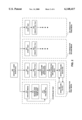
- FIG. 1 is a block diagram illustrating an example of a distributed computing system upon which one embodiment of the present invention operates.
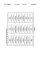
- FIG. 2 presents flow charts of some of the activities initiated through graphical user interface 200 in order to test a file system in accordance with an embodiment of the present invention.
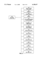
- FIG. 3 is a diagram illustrating part of the software architecture for one embodiment of the present invention.
- FIG. 4 is a diagram illustrating some components of a file test data structure, for storing parameters involved in generating test file references in accordance with an embodiment of the present invention.
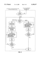
- FIG. 5 is a flow chart illustrating some of the actions involved in determining a source of a failure in accordance with an embodiment of the present invention.
- FIG. 6 illustrates an example in which the source of a failed file reference is isolated in accordance with an embodiment of the present invention.
- FIG. 1 is a block diagram illustrating a distributed computing system upon which one embodiment of the present invention operates.
- a plurality of workstations, 100 and 110 are coupled through network 140 to server 130.
- workstations 100 and 110 may be any type of computing node in a distributed computing system. This includes, but is not limited to, workstations, personal computers, mainframe computers, supercomputers and device controllers.
- Network 140 may be any type of communication network through which computers can communicate. This includes, but is not limited to, local area networks, such as Ethernet or Token ring networks, and wide area networks, such as the Internet.
- Server 130 may be any type of computational server capable of storing data that can be accessed by other computer systems over network 140.
- workstations 100 and 110 and server 130 include internal components, some of which are illustrated in FIG. 1.
- Workstation 100 includes local disk 106, local random access memory 102 and LAN card 108.
- Local random access memory 102 includes test code 104, which can be used to perform a series of test file system accesses that allows a failed access to be retried.
- Local LAN card 108 includes components to connect workstation 100 with network 140.
- Workstation 110 includes local disk 116, local random access memory 112 and local LAN card 118.
- Local random access memory 112 includes test code 114, which can be used to perform a series of test file system accesses, and allows a failed access to be retried.
- Local LAN card 118 includes components to connect workstation 100 with network 140.
- Server 130 includes local disk 136 and local random access memory 132.
- Local random access memory 132 includes test code 134, which can be used to perform a series of file system accesses, and allows a failed access to be retried.
- server 130 additionally includes local area network (LAN) card 139, which includes components to connect server 130 with network 140. (Workstations 100 and 110 may also include LAN cards--but these are not shown).
- Server 130 also includes local disk 138 to store additional files. Server 130 may include additional disk drives, but these are not shown.
- FIG. 1 illustrates a distributed computing system upon which one embodiment of the present invention operates.
- the present invention may operate on a wide range of computing systems, and is not specifically limited to distributed computing systems.
- the present invention may also operate on mainframe computing systems, stand-alone computing systems, personal computer systems and even portable computer systems, such as laptop computers.
- the present invention can be used to test any computing system with a file system.
- file accesses take place as follows.
- a file access originating from workstation 100 can be targeted to a file on local disk 106.
- This type of file access involves only local computing resources and components within workstation 100.
- workstation 100 can make a file access, such as a read or write operation, to a remote file located on server 130.
- the file may be located on disk 136 on server 130.
- the file access proceeds across network 140, through LAN card 139 to disk 136.
- various hardware and software components within workstation 100, network 140 and server can potentially cause failures.
- workstation 100 may be able to access files on disk 116 within workstation 110 This embodiment also allows accesses to any or all disks in the system.
- workstations 110 and 120 or server 130 can all access disks 106, 116 136 and 138 simultaneously.
- test code such as test code 104 in workstation 110, performs read and write accesses to files on various storage devices located on various workstations and file servers.
- a test pattern is typically written to a particular location within a file located on a certain storage device. The location is subsequently read to ensure that the test pattern is read back properly from the file.
- files are stored on disk drive devices.
- the invention can be applied to any type of device on which files can be stored. This includes, but is not limited to, tape storage devices, optical storage devices, floppy disks, RAM disks and floating gate storage devices.
- FIG. 2 is presents flow charts of some of the activities initiated through graphical user interface 200 in order to test a file system in accordance with an embodiment of the present invention.
- these activities are performed by file system testing tools contained within test code, such as test code 104, 114 and 114, on workstations 100, 110 and server 130, respectively.
- file system testing activities are accomplished through hardware and software resources distributed throughout a computer system to be tested.
- file system testing is controlled through graphical user interface 200.
- the first step in file system testing is to initialize the test 210. This involves discovering the different storage devices (or media) 211 on the computer system that require testing. This discovery process may involve scanning through the physical devices on the system, or otherwise scanning through the file system, in order to determine where files can be stored in the computer system.
- the next step is to receive parameters 212 from a user of the testing system to define the scope of a particular test. These parameters may include, block size for test file references, numbers of iterations for certain tests, and test pattern types. Any other parameters relevant to testing may be gathered at this time. Alternatively, the user can load a file containing pre-recorded file test parameters 213.
- the test system creates and spawns off a plurality of independently executing threads, wherein each thread is dedicated to testing a particular storage device.
- thread 220 is dedicated to testing a first media
- thread 230 is dedicated to testing a second media
- thread 240 is dedicated to testing a third media.
- This multi-threading can greatly improve performance, because the performance of file system testing is primarily limited by the slow speed of storage devices. Hence, a single processor is typically capable of testing a large number of storage devices concurrently.
- file system testing is not multi-threaded, and storage devices are tested one at a time.
- each thread performs a number of operations to test a particular media (or storage device).
- testing begins in state 221, which is a start state for the testing.
- Thread 220 next proceeds to state 222.
- state 222 a test file is created on the target storage device.
- Thread 220 next proceeds to state 223, in which a series of file references to the test file are generated; the results of the file references are then verified.
- the verification includes determining if a test pattern that is written to a file at a particular location can be read back properly from the particular location.
- Thread 220 next proceeds to state 224.
- state 224 thread 220 displays expected and received data to a display.
- Thread 220 next proceeds to state 225.
- state 225 if a failure was detected in a file access, the failure is retried in an attempt to isolate the cause of the failure.
- the user can alternatively decide to proceed to state 226, in which parameters related to the failure are stored to a file.
- This file can be transferred to a second location in the computer system in order to retry a failed file system access from the second location in order to isolate the source of the failure. States 225 and 226 are described in more detail with reference to FIG. 5 below.
- threads perform the same series of actions for a different storage media.
- thread 230 performs the same actions in testing a second media
- thread 240 performs the same actions in testing a third media.
- FIG. 3 is a diagram illustrating portions of the software architecture for one embodiment of the present invention.
- FIG. 3 illustrates a collection of functions, which are used by one embodiment of the present invention to perform the actions illustrated in FIG. 2. These functions collectively form part of file system testing architecture 300.
- Function WinMain 301 registers and displays a window class and process messages from the main message loop.
- Function WinMain 301 takes as input an instance handle, a previous handle and command line arguments and a Windows Tm display mode. It returns a FALSE value if there is a failure, or it returns a message when exiting.
- Function InitApp 302 initializes the window class and all resources and styles, it then registers the class.
- Function InitInst 303 initializes a window class as well as resources and styles, it then registers the class.
- Function WindowFunc 304 is called by Windows95TM, and is passed messages from the message queue.
- Function SetParam 305 processes messages for the set parameter dialog box.
- Function GetDriveInfo 306 obtains a list of drives and share names. It returns a FALSE value if it was unable to populate the device linked list with the test objects that were discovered.
- Function DisplayStatus 307 processes messages for the main status dialog box.
- Function SpawnFileThreads 308 spawns individual threads for each of the test objects selected.
- Function StartTest 309 is the main testing function. It controls logic for reading, writing and verifying data to and from the target client.
- Function CreateSeqFile 310 calls all functions required to create a sequential test file, and calls an Error function if necessary.
- Function VerifySeqFile 311 calls all functions required to verify a sequential test file, and calls an Error function if necessary.
- Function GetFileHandle 312 opens a file with the proper read and write modes.
- Function CreatePattern 313 creates a test pattern for the test file references.
- Function PatternHeader 314 writes or reads a pattern header of a test file.
- Function FileInfo 315 reads or writes block and loop header information.
- Function VerifyFile 316 returns TRUE if a comparison is successful and returns FALSE if it is unable to read a file, or if a comparison fails.
- Function CheckEvents 317 checks for events from the Display Status dialog box, it returns FALSE if the exit button is depressed.
- Function WaitCleanUp 318 waits for a stop event to return to the calling process and displays data if the variable "display event" is set.
- Function DisplayTestStatus 319 displays status by displaying a field from a struct to a dialog window handle in the struct.
- Function ErrorPass 320 displays an error to the appropriate dialog boxes.
- Function Debug 321 displays the 8 bytes before and after a corrupted byte. This function is invoked either manually, from the Main Windows menu, or when a test in progress fails.
- Function FormMiscompare 322 displays the 32 bytes before and after a corrupted byte.
- Function TestParams 323 retrieves the test parameters from a failed pass from a file.
- Function Retry 324 allows the user to retry a filed read of a block. It also saves test parameters to file.
- Function About 325 processes messages for the "About" dialog box.
- Function Save 326 saves system parameters.
- Function Load 327 loads system parameters.
- FIG. 4 is a diagram illustrating some components of a file test data structure 400, for storing parameters involved in generating test file references in accordance with an embodiment of the present invention.
- File test data structure 400 is used during testing to keep track of the progress of the test.
- information from structure 400 is used to retry the failed file access operation, as is illustrated in states 225 and 226 of FIG. 2.
- file test data structure is implemented as a "struct" in the C programming language.
- file test data structure 400 includes the following components.
- “Links to other structs” 402 contains a linkage, which is used to form a linked list of similar structures.
- each struct in the linked list is associated with a particular thread, which is in turn associated with a test of a different storage device.
- Thread ID 404 contains an identifier for the thread associated with structure 400.
- Thread handle 406, contains a handle that is used to manipulate the thread.
- Drive ID 408 includes a character string representing the storage device to be tested using structure 400.
- "Loop counter number of blocks read” 410 contains a counter which keeps track of the progress of block reads during a test.
- “Number of test iterations” 412 stores the number of iterations for a test.
- “Iterations for block writes” 414 keeps track of the number of block writes to be performed during a test involving structure 400.
- Character buffer 416 stores a test pattern, which is written to a file during a test.
- Verify buffer 418 stores the results of a read operation from the test file. This result is compared with the original test pattern stored in character buffer 416 in order to determine if the block was written to the file and read back properly.
- File handle 420 includes a handle for accessing the file involved in the test.
- Error location 422 includes the location within the file of a failed file access.
- Last status 424 includes the last status of a test in progress.
- Retry list 426 includes a list of failed file system accesses to be retried.
- Retry counter 428 keeps track of the number of retries that have occurred during a test.
- "Disk time outs" 430 keeps track of the number of disk retries.
- FIG. 5 is a flow chart illustrating some of the actions involved in determining the source of a failure in accordance with an embodiment of the present invention.
- FIG. 5 illustrates in more detail the actions involved in retrying a failure and storing a failure to a file in states 225 and 226 of FIG. 2, respectively, for one embodiment of the present invention.
- the system first enters state 502 from state 224 in FIG. 2.
- state 502 the system determines if a failure was detected. If not, the system returns to state 223 in FIG. 2 to continue generating and verifying file requests. If so, the system proceeds to state 504.
- state 504 the system determines whether to retry to failure, or to save the failure to a file. This can be determined by prompting a system user for a decision, or it can be determined automatically, based upon the type of error encountered or the type of testing taking place. If a retry is indicated, the system proceeds to state 506. If a file save is indicated, the system proceeds to state 512.
- trouble shooting may include: replacing a hardware or software component of the computer system; inserting debug code into the computer system; inserting new firmware into the computer system; or changing nothing in the system.
- the system next proceeds to state 508.
- state 508 the system reconstructs and retries the file reference that caused the failure using parameters contained within structure 400 in FIG. 4.
- the system next proceeds to state 510.
- state 510 the system determines whether or not the source of failure has been found. This may be determined by asking a human user, or it may be determined automatically based upon the type of trouble shooting taking place and the result of the retry. If the source of failure is found, the system proceeds to state 522, which is an end state. Otherwise, the system returns to state 504, or to state 506, to repeat the process as necessary to find the source of failure.
- state 512 a file save was indicated. Failure data from data structure 400, and possibly from additional sources, is encapsulated and saved to a file. The system then proceeds to state 514. In state 514, the failure data contained in the file is moved to a different location in the system in order to retry the filed file system access from the different location, to hopefully isolate the source of failure. The system then proceeds to state 516.
- this trouble shooting may include: replacing a hardware or software component of the computer system; inserting debug code into the computer system; inserting new firmware into the computer system; or changing nothing in the system.
- the system next proceeds to state 518.
- state 518 the system reconstructs and retries the file reference that caused the failure using parameters contained within structure 400 in FIG. 4.
- the system next proceeds to state 520.
- state 520 the system determines whether or not the source of failure has been found. This may be determined by asking a human user, or it may be determined automatically based upon the type of trouble shooting taking place and the result of the retry. If the source of failure is found, the system proceeds to state 522, which is an end state. Otherwise, the system returns to state 504, or to state 516, to repeat the process as necessary to find the source of failure.
- FIG. 6 illustrates an example in which the source of a failed file reference is isolated in accordance with an embodiment of the present invention.
- the computer system is identical to the computer system disclosed in FIG. 1.
- This example starts by generating references from workstation 100 to a file located on server 130. This corresponds to state 223 from FIG. 2.
- a failure is detected during a file reference, and the failure is saved to a file. This corresponds to state 512 in FIG. 5.
- the saved file, and if necessary the test program is moved to workstation 1 10, and the failed file reference is retried from workstation 110. This corresponds to state 158 in FIG. 5.
- a failure similarly occurs when attempting the same file reference from workstation 110.
- the failure is saved to a file so it can be retried from a different location.
- the saved file, and if necessary the test program is moved directly to server 130, and the failed file reference is retried from server 130.
- a failure does not occur, which suggests that the failure arose during communications between the workstations and server 130.
- LAN card 139 is swapped with a different LAN card, and the failed file access is retried from workstation 100. This troubleshooting corresponds to state 516 in FIG. 5. In this example, the failure persists despite the replacement of LAN card 139.
- one embodiment of the present invention allows a failed file reference to be easily retried from a variety of locations in a distributed system. This makes it possible to rapidly locate the source of the failure.
Abstract
Description
Claims (21)
Priority Applications (1)
| Application Number | Priority Date | Filing Date | Title |
|---|---|---|---|
| US09/006,778 US6148417A (en) | 1998-01-14 | 1998-01-14 | Method for determining a source of failure during a file system access |
Applications Claiming Priority (1)
| Application Number | Priority Date | Filing Date | Title |
|---|---|---|---|
| US09/006,778 US6148417A (en) | 1998-01-14 | 1998-01-14 | Method for determining a source of failure during a file system access |
Publications (1)
| Publication Number | Publication Date |
|---|---|
| US6148417A true US6148417A (en) | 2000-11-14 |
Family
ID=21722529
Family Applications (1)
| Application Number | Title | Priority Date | Filing Date |
|---|---|---|---|
| US09/006,778 Expired - Lifetime US6148417A (en) | 1998-01-14 | 1998-01-14 | Method for determining a source of failure during a file system access |
Country Status (1)
| Country | Link |
|---|---|
| US (1) | US6148417A (en) |
Cited By (27)
| Publication number | Priority date | Publication date | Assignee | Title |
|---|---|---|---|---|
| US6226761B1 (en) * | 1998-09-24 | 2001-05-01 | International Business Machines Corporation | Post dump garbage collection |
| US6237139B1 (en) * | 1997-09-03 | 2001-05-22 | Fujitsu Limited | Object-oriented programming support system |
| US6438712B1 (en) * | 1998-10-09 | 2002-08-20 | Oak Technology, Inc. | Quick identification of defect-uncovering files |
| US20040015722A1 (en) * | 2002-07-22 | 2004-01-22 | Finisar Corporation | Scalable network attached storage (NAS) testing tool |
| US20040015317A1 (en) * | 2002-07-22 | 2004-01-22 | Finisar Corporation | Scalable multithreaded system testing tool |
| US20040030958A1 (en) * | 2002-03-29 | 2004-02-12 | Erik Moerman | Integrated circuit with direct debugging architecture |
| US20040194063A1 (en) * | 2003-03-28 | 2004-09-30 | Joel Pereira | System and method for automated testing of a software module |
| US6865689B1 (en) * | 2001-06-29 | 2005-03-08 | Sun Microsystems, Inc. | Method and apparatus for fault isolation on network loops using low level error counters |
| DE102004039886A1 (en) * | 2004-08-17 | 2006-03-09 | Endress + Hauser Flowtec Ag | Method for operating a field device of automation technology |
| US20060107328A1 (en) * | 2004-11-15 | 2006-05-18 | Microsoft Corporation | Isolated computing environment anchored into CPU and motherboard |
| US7266538B1 (en) * | 2002-03-29 | 2007-09-04 | Emc Corporation | Methods and apparatus for controlling access to data in a data storage system |
| US20080184026A1 (en) * | 2007-01-29 | 2008-07-31 | Hall Martin H | Metered Personal Computer Lifecycle |
| US20080263412A1 (en) * | 2003-05-08 | 2008-10-23 | Micron Technology, Inc. | Program failure recovery |
| US20090193298A1 (en) * | 2008-01-30 | 2009-07-30 | International Business Machines Corporation | System and method of fault detection, diagnosis and prevention for complex computing systems |
| US8176564B2 (en) | 2004-11-15 | 2012-05-08 | Microsoft Corporation | Special PC mode entered upon detection of undesired state |
| US8336085B2 (en) | 2004-11-15 | 2012-12-18 | Microsoft Corporation | Tuning product policy using observed evidence of customer behavior |
| US8347078B2 (en) | 2004-10-18 | 2013-01-01 | Microsoft Corporation | Device certificate individualization |
| US8353046B2 (en) | 2005-06-08 | 2013-01-08 | Microsoft Corporation | System and method for delivery of a modular operating system |
| US8438645B2 (en) | 2005-04-27 | 2013-05-07 | Microsoft Corporation | Secure clock with grace periods |
| US8700535B2 (en) | 2003-02-25 | 2014-04-15 | Microsoft Corporation | Issuing a publisher use license off-line in a digital rights management (DRM) system |
| US8725646B2 (en) | 2005-04-15 | 2014-05-13 | Microsoft Corporation | Output protection levels |
| US8781969B2 (en) | 2005-05-20 | 2014-07-15 | Microsoft Corporation | Extensible media rights |
| US20150186233A1 (en) * | 2013-12-30 | 2015-07-02 | Lenovo (Singapore) Pte, Ltd. | Remote diagnostics for a computing device |
| US9189605B2 (en) | 2005-04-22 | 2015-11-17 | Microsoft Technology Licensing, Llc | Protected computing environment |
| US9363481B2 (en) | 2005-04-22 | 2016-06-07 | Microsoft Technology Licensing, Llc | Protected media pipeline |
| US9436804B2 (en) | 2005-04-22 | 2016-09-06 | Microsoft Technology Licensing, Llc | Establishing a unique session key using a hardware functionality scan |
| US10025788B2 (en) | 2015-09-29 | 2018-07-17 | International Business Machines Corporation | Detection of file corruption in a distributed file system |
Citations (4)
| Publication number | Priority date | Publication date | Assignee | Title |
|---|---|---|---|---|
| US5564011A (en) * | 1993-10-05 | 1996-10-08 | International Business Machines Corporation | System and method for maintaining file data access in case of dynamic critical sector failure |
| US5640556A (en) * | 1992-11-25 | 1997-06-17 | Fujitsu Limited | Synchronous/asynchronous client server access based upon database file record attribute |
| US5659682A (en) * | 1994-06-16 | 1997-08-19 | International Business Machines Corporation | Scheme to determine completion of directory operations for server recovery |
| US5909542A (en) * | 1996-11-20 | 1999-06-01 | Cfi Proservices, Inc. | Distributed computing system for executing intercommunicating applications programs |
-
1998
- 1998-01-14 US US09/006,778 patent/US6148417A/en not_active Expired - Lifetime
Patent Citations (4)
| Publication number | Priority date | Publication date | Assignee | Title |
|---|---|---|---|---|
| US5640556A (en) * | 1992-11-25 | 1997-06-17 | Fujitsu Limited | Synchronous/asynchronous client server access based upon database file record attribute |
| US5564011A (en) * | 1993-10-05 | 1996-10-08 | International Business Machines Corporation | System and method for maintaining file data access in case of dynamic critical sector failure |
| US5659682A (en) * | 1994-06-16 | 1997-08-19 | International Business Machines Corporation | Scheme to determine completion of directory operations for server recovery |
| US5909542A (en) * | 1996-11-20 | 1999-06-01 | Cfi Proservices, Inc. | Distributed computing system for executing intercommunicating applications programs |
Cited By (40)
| Publication number | Priority date | Publication date | Assignee | Title |
|---|---|---|---|---|
| US6237139B1 (en) * | 1997-09-03 | 2001-05-22 | Fujitsu Limited | Object-oriented programming support system |
| US6226761B1 (en) * | 1998-09-24 | 2001-05-01 | International Business Machines Corporation | Post dump garbage collection |
| US6438712B1 (en) * | 1998-10-09 | 2002-08-20 | Oak Technology, Inc. | Quick identification of defect-uncovering files |
| US6865689B1 (en) * | 2001-06-29 | 2005-03-08 | Sun Microsystems, Inc. | Method and apparatus for fault isolation on network loops using low level error counters |
| US7266538B1 (en) * | 2002-03-29 | 2007-09-04 | Emc Corporation | Methods and apparatus for controlling access to data in a data storage system |
| US20040030958A1 (en) * | 2002-03-29 | 2004-02-12 | Erik Moerman | Integrated circuit with direct debugging architecture |
| US6889159B2 (en) * | 2002-07-22 | 2005-05-03 | Finisar Corporation | Scalable multithreaded system testing tool |
| US20040015317A1 (en) * | 2002-07-22 | 2004-01-22 | Finisar Corporation | Scalable multithreaded system testing tool |
| US7114106B2 (en) * | 2002-07-22 | 2006-09-26 | Finisar Corporation | Scalable network attached storage (NAS) testing tool |
| US20040015722A1 (en) * | 2002-07-22 | 2004-01-22 | Finisar Corporation | Scalable network attached storage (NAS) testing tool |
| US8719171B2 (en) | 2003-02-25 | 2014-05-06 | Microsoft Corporation | Issuing a publisher use license off-line in a digital rights management (DRM) system |
| US8700535B2 (en) | 2003-02-25 | 2014-04-15 | Microsoft Corporation | Issuing a publisher use license off-line in a digital rights management (DRM) system |
| US20040194063A1 (en) * | 2003-03-28 | 2004-09-30 | Joel Pereira | System and method for automated testing of a software module |
| US7783934B2 (en) * | 2003-05-08 | 2010-08-24 | Micron Technology, Inc. | Program failure recovery |
| US8074122B2 (en) * | 2003-05-08 | 2011-12-06 | Micron Technology, Inc. | Program failure recovery |
| US20100325479A1 (en) * | 2003-05-08 | 2010-12-23 | Micron Technology, Inc. | Program failure recovery |
| US20080263412A1 (en) * | 2003-05-08 | 2008-10-23 | Micron Technology, Inc. | Program failure recovery |
| US20060059283A1 (en) * | 2004-08-17 | 2006-03-16 | Walter Borst | Method for operating a field device for automation technology |
| US7103689B2 (en) | 2004-08-17 | 2006-09-05 | Endress + Hauser Flowtec Ag | Method for automatic replacement in automation technology field devices where swapping is not necessary |
| DE102004039886A1 (en) * | 2004-08-17 | 2006-03-09 | Endress + Hauser Flowtec Ag | Method for operating a field device of automation technology |
| US8347078B2 (en) | 2004-10-18 | 2013-01-01 | Microsoft Corporation | Device certificate individualization |
| US9336359B2 (en) | 2004-10-18 | 2016-05-10 | Microsoft Technology Licensing, Llc | Device certificate individualization |
| US8336085B2 (en) | 2004-11-15 | 2012-12-18 | Microsoft Corporation | Tuning product policy using observed evidence of customer behavior |
| US9224168B2 (en) | 2004-11-15 | 2015-12-29 | Microsoft Technology Licensing, Llc | Tuning product policy using observed evidence of customer behavior |
| US8176564B2 (en) | 2004-11-15 | 2012-05-08 | Microsoft Corporation | Special PC mode entered upon detection of undesired state |
| US8464348B2 (en) * | 2004-11-15 | 2013-06-11 | Microsoft Corporation | Isolated computing environment anchored into CPU and motherboard |
| US20060107328A1 (en) * | 2004-11-15 | 2006-05-18 | Microsoft Corporation | Isolated computing environment anchored into CPU and motherboard |
| US8725646B2 (en) | 2005-04-15 | 2014-05-13 | Microsoft Corporation | Output protection levels |
| US9189605B2 (en) | 2005-04-22 | 2015-11-17 | Microsoft Technology Licensing, Llc | Protected computing environment |
| US9363481B2 (en) | 2005-04-22 | 2016-06-07 | Microsoft Technology Licensing, Llc | Protected media pipeline |
| US9436804B2 (en) | 2005-04-22 | 2016-09-06 | Microsoft Technology Licensing, Llc | Establishing a unique session key using a hardware functionality scan |
| US8438645B2 (en) | 2005-04-27 | 2013-05-07 | Microsoft Corporation | Secure clock with grace periods |
| US8781969B2 (en) | 2005-05-20 | 2014-07-15 | Microsoft Corporation | Extensible media rights |
| US8353046B2 (en) | 2005-06-08 | 2013-01-08 | Microsoft Corporation | System and method for delivery of a modular operating system |
| US20080184026A1 (en) * | 2007-01-29 | 2008-07-31 | Hall Martin H | Metered Personal Computer Lifecycle |
| US8949671B2 (en) * | 2008-01-30 | 2015-02-03 | International Business Machines Corporation | Fault detection, diagnosis, and prevention for complex computing systems |
| US20090193298A1 (en) * | 2008-01-30 | 2009-07-30 | International Business Machines Corporation | System and method of fault detection, diagnosis and prevention for complex computing systems |
| US20150186233A1 (en) * | 2013-12-30 | 2015-07-02 | Lenovo (Singapore) Pte, Ltd. | Remote diagnostics for a computing device |
| US9535816B2 (en) * | 2013-12-30 | 2017-01-03 | Lenovo (Singapore) | Remote diagnostics for a computing device |
| US10025788B2 (en) | 2015-09-29 | 2018-07-17 | International Business Machines Corporation | Detection of file corruption in a distributed file system |
Similar Documents
| Publication | Publication Date | Title |
|---|---|---|
| US6148417A (en) | Method for determining a source of failure during a file system access | |
| US9514029B2 (en) | Partial recording of a computer program execution for replay | |
| US7698691B2 (en) | Server application state | |
| US9122601B2 (en) | Advancing and rewinding a replayed program execution | |
| US7526750B2 (en) | Object-based systematic state space exploration of software | |
| US5557740A (en) | Method and system for providing device support testing for a plurality of operating systems | |
| US5513315A (en) | System and method for automatic testing of computer software | |
| US7475387B2 (en) | Problem determination using system run-time behavior analysis | |
| US6532552B1 (en) | Method and system for performing problem determination procedures in hierarchically organized computer systems | |
| US20070220370A1 (en) | Mechanism to generate functional test cases for service oriented architecture (SOA) applications from errors encountered in development and runtime | |
| US20140089903A1 (en) | Sampling Based Runtime Optimizer for Efficient Debugging of Applications | |
| JPH11161477A (en) | Testing method for software installed and customized computer system | |
| JPH11161476A (en) | Data base for facilitating software installation and testing for custom-made computer system | |
| US20020147942A1 (en) | Method and system for performing load testings on software applications | |
| US6629158B1 (en) | System, apparatus, and method for configuring an array controller | |
| US9183122B2 (en) | Automated program testing to facilitate recreation of test failure | |
| CN106991048A (en) | Webpage method of testing and device | |
| US6438714B1 (en) | Method and apparatus for testing large arrays of storage devices | |
| US20080010536A1 (en) | Breakpoints with Separate Conditions | |
| US7376676B2 (en) | Method, system, and program for autonomic copy services solutions | |
| US8997048B1 (en) | Method and apparatus for profiling a virtual machine | |
| US7152189B2 (en) | Testing distributed services by using multiple boots to timeshare a single computer | |
| US6490544B1 (en) | System for testing a multi-tasking computing device | |
| US7680841B2 (en) | Determining whether data written to source storage locations according to a write order is copied to corresponding target storage locations in the write order | |
| US7386434B1 (en) | Method and apparatus for creating integrated circuit simulator test source files |
Legal Events
| Date | Code | Title | Description |
|---|---|---|---|
| AS | Assignment |
Owner name: MICRON ELECTRONICS, INC., IDAHO Free format text: ASSIGNMENT OF ASSIGNORS INTEREST;ASSIGNOR:DA SILVA, LUIS A.;REEL/FRAME:009394/0793 Effective date: 19980501 |
|
| STCF | Information on status: patent grant |
Free format text: PATENTED CASE |
|
| AS | Assignment |
Owner name: MEI CALIFORNIA, INC., CALIFORNIA Free format text: ASSIGNMENT OF ASSIGNORS INTEREST;ASSIGNOR:MICRON ELECTRONICS, INC.;REEL/FRAME:011658/0956 Effective date: 20010322 |
|
| AS | Assignment |
Owner name: MICRON TECHNOLOGY, INC., IDAHO Free format text: ASSIGNMENT OF ASSIGNORS INTEREST;ASSIGNOR:MEI CALIFORNIA, INC.;REEL/FRAME:013645/0313 Effective date: 20010322 |
|
| FPAY | Fee payment |
Year of fee payment: 4 |
|
| FEPP | Fee payment procedure |
Free format text: PAYOR NUMBER ASSIGNED (ORIGINAL EVENT CODE: ASPN); ENTITY STATUS OF PATENT OWNER: LARGE ENTITY |
|
| FPAY | Fee payment |
Year of fee payment: 8 |
|
| FPAY | Fee payment |
Year of fee payment: 12 |
|
| AS | Assignment |
Owner name: U.S. BANK NATIONAL ASSOCIATION, AS COLLATERAL AGENT, CALIFORNIA Free format text: SECURITY INTEREST;ASSIGNOR:MICRON TECHNOLOGY, INC.;REEL/FRAME:038669/0001 Effective date: 20160426 Owner name: U.S. BANK NATIONAL ASSOCIATION, AS COLLATERAL AGEN Free format text: SECURITY INTEREST;ASSIGNOR:MICRON TECHNOLOGY, INC.;REEL/FRAME:038669/0001 Effective date: 20160426 |
|
| AS | Assignment |
Owner name: MORGAN STANLEY SENIOR FUNDING, INC., AS COLLATERAL AGENT, MARYLAND Free format text: PATENT SECURITY AGREEMENT;ASSIGNOR:MICRON TECHNOLOGY, INC.;REEL/FRAME:038954/0001 Effective date: 20160426 Owner name: MORGAN STANLEY SENIOR FUNDING, INC., AS COLLATERAL Free format text: PATENT SECURITY AGREEMENT;ASSIGNOR:MICRON TECHNOLOGY, INC.;REEL/FRAME:038954/0001 Effective date: 20160426 |
|
| AS | Assignment |
Owner name: U.S. BANK NATIONAL ASSOCIATION, AS COLLATERAL AGENT, CALIFORNIA Free format text: CORRECTIVE ASSIGNMENT TO CORRECT THE REPLACE ERRONEOUSLY FILED PATENT #7358718 WITH THE CORRECT PATENT #7358178 PREVIOUSLY RECORDED ON REEL 038669 FRAME 0001. ASSIGNOR(S) HEREBY CONFIRMS THE SECURITY INTEREST;ASSIGNOR:MICRON TECHNOLOGY, INC.;REEL/FRAME:043079/0001 Effective date: 20160426 Owner name: U.S. BANK NATIONAL ASSOCIATION, AS COLLATERAL AGEN Free format text: CORRECTIVE ASSIGNMENT TO CORRECT THE REPLACE ERRONEOUSLY FILED PATENT #7358718 WITH THE CORRECT PATENT #7358178 PREVIOUSLY RECORDED ON REEL 038669 FRAME 0001. ASSIGNOR(S) HEREBY CONFIRMS THE SECURITY INTEREST;ASSIGNOR:MICRON TECHNOLOGY, INC.;REEL/FRAME:043079/0001 Effective date: 20160426 |
|
| AS | Assignment |
Owner name: MICRON TECHNOLOGY, INC., IDAHO Free format text: RELEASE BY SECURED PARTY;ASSIGNOR:U.S. BANK NATIONAL ASSOCIATION, AS COLLATERAL AGENT;REEL/FRAME:047243/0001 Effective date: 20180629 |
|
| AS | Assignment |
Owner name: MICRON TECHNOLOGY, INC., IDAHO Free format text: RELEASE BY SECURED PARTY;ASSIGNOR:MORGAN STANLEY SENIOR FUNDING, INC., AS COLLATERAL AGENT;REEL/FRAME:050937/0001 Effective date: 20190731 |