US6117101A - Circumferential ablation device assembly - Google Patents
Circumferential ablation device assembly Download PDFInfo
- Publication number
- US6117101A US6117101A US09/199,736 US19973698A US6117101A US 6117101 A US6117101 A US 6117101A US 19973698 A US19973698 A US 19973698A US 6117101 A US6117101 A US 6117101A
- Authority
- US
- United States
- Prior art keywords
- circumferential
- tissue
- ablation
- assembly
- ultrasound
- Prior art date
- Legal status (The legal status is an assumption and is not a legal conclusion. Google has not performed a legal analysis and makes no representation as to the accuracy of the status listed.)
- Expired - Lifetime
Links
Images


Classifications
-
- A—HUMAN NECESSITIES
- A61—MEDICAL OR VETERINARY SCIENCE; HYGIENE
- A61B—DIAGNOSIS; SURGERY; IDENTIFICATION
- A61B18/00—Surgical instruments, devices or methods for transferring non-mechanical forms of energy to or from the body
- A61B18/04—Surgical instruments, devices or methods for transferring non-mechanical forms of energy to or from the body by heating
- A61B18/12—Surgical instruments, devices or methods for transferring non-mechanical forms of energy to or from the body by heating by passing a current through the tissue to be heated, e.g. high-frequency current
- A61B18/14—Probes or electrodes therefor
- A61B18/1492—Probes or electrodes therefor having a flexible, catheter-like structure, e.g. for heart ablation
-
- A—HUMAN NECESSITIES
- A61—MEDICAL OR VETERINARY SCIENCE; HYGIENE
- A61B—DIAGNOSIS; SURGERY; IDENTIFICATION
- A61B18/00—Surgical instruments, devices or methods for transferring non-mechanical forms of energy to or from the body
-
- A—HUMAN NECESSITIES
- A61—MEDICAL OR VETERINARY SCIENCE; HYGIENE
- A61M—DEVICES FOR INTRODUCING MEDIA INTO, OR ONTO, THE BODY; DEVICES FOR TRANSDUCING BODY MEDIA OR FOR TAKING MEDIA FROM THE BODY; DEVICES FOR PRODUCING OR ENDING SLEEP OR STUPOR
- A61M25/00—Catheters; Hollow probes
- A61M25/10—Balloon catheters
- A61M25/1002—Balloon catheters characterised by balloon shape
-
- A—HUMAN NECESSITIES
- A61—MEDICAL OR VETERINARY SCIENCE; HYGIENE
- A61N—ELECTROTHERAPY; MAGNETOTHERAPY; RADIATION THERAPY; ULTRASOUND THERAPY
- A61N7/00—Ultrasound therapy
- A61N7/02—Localised ultrasound hyperthermia
-
- A—HUMAN NECESSITIES
- A61—MEDICAL OR VETERINARY SCIENCE; HYGIENE
- A61B—DIAGNOSIS; SURGERY; IDENTIFICATION
- A61B17/00—Surgical instruments, devices or methods, e.g. tourniquets
- A61B17/00234—Surgical instruments, devices or methods, e.g. tourniquets for minimally invasive surgery
- A61B2017/00238—Type of minimally invasive operation
- A61B2017/00243—Type of minimally invasive operation cardiac
-
- A—HUMAN NECESSITIES
- A61—MEDICAL OR VETERINARY SCIENCE; HYGIENE
- A61B—DIAGNOSIS; SURGERY; IDENTIFICATION
- A61B18/00—Surgical instruments, devices or methods for transferring non-mechanical forms of energy to or from the body
- A61B2018/00053—Mechanical features of the instrument of device
- A61B2018/00059—Material properties
- A61B2018/00071—Electrical conductivity
- A61B2018/00083—Electrical conductivity low, i.e. electrically insulating
-
- A—HUMAN NECESSITIES
- A61—MEDICAL OR VETERINARY SCIENCE; HYGIENE
- A61B—DIAGNOSIS; SURGERY; IDENTIFICATION
- A61B18/00—Surgical instruments, devices or methods for transferring non-mechanical forms of energy to or from the body
- A61B2018/00053—Mechanical features of the instrument of device
- A61B2018/00107—Coatings on the energy applicator
- A61B2018/00148—Coatings on the energy applicator with metal
-
- A—HUMAN NECESSITIES
- A61—MEDICAL OR VETERINARY SCIENCE; HYGIENE
- A61B—DIAGNOSIS; SURGERY; IDENTIFICATION
- A61B18/00—Surgical instruments, devices or methods for transferring non-mechanical forms of energy to or from the body
- A61B2018/00053—Mechanical features of the instrument of device
- A61B2018/00214—Expandable means emitting energy, e.g. by elements carried thereon
-
- A—HUMAN NECESSITIES
- A61—MEDICAL OR VETERINARY SCIENCE; HYGIENE
- A61M—DEVICES FOR INTRODUCING MEDIA INTO, OR ONTO, THE BODY; DEVICES FOR TRANSDUCING BODY MEDIA OR FOR TAKING MEDIA FROM THE BODY; DEVICES FOR PRODUCING OR ENDING SLEEP OR STUPOR
- A61M2210/00—Anatomical parts of the body
- A61M2210/12—Blood circulatory system
- A61M2210/125—Heart
-
- A—HUMAN NECESSITIES
- A61—MEDICAL OR VETERINARY SCIENCE; HYGIENE
- A61N—ELECTROTHERAPY; MAGNETOTHERAPY; RADIATION THERAPY; ULTRASOUND THERAPY
- A61N7/00—Ultrasound therapy
- A61N7/02—Localised ultrasound hyperthermia
- A61N7/022—Localised ultrasound hyperthermia intracavitary
Definitions
- the present invention is a surgical device. More specifically, it is a circumferential ablation device assembly which is adapted to ablate a selected circumferential region of tissue which is located either along a pulmonary vein wall, which forms a circumferential conduction block against conduction along the longitudinal axis of the pulmonary vein wall, or along a left posterior atrial wall which surrounds a pulmonary vein ostium and electrically isolates the vein and the ostium from the rest of the atrium.
- body space is herein intended to mean any cavity or lumen within the body which is defined at least in part by a tissue wall.
- tissue wall For example, the cardiac chambers, the uterus, the regions of the gastrointestinal tract, and the arterial or venous vessels are all considered illustrative examples of body spaces within the intended meaning.
- lumen including derivatives thereof, is herein intended to mean any body space which is circumscribed along a length by a tubular tissue wall and which terminates at each of two ends in at least one opening that communicates externally of the body space.
- the large and small intestines, the vas deferens, the trachea, and the fallopian tubes are all illustrative examples of lumens within the intended meaning.
- Blood vessels are also herein considered lumens, including regions of the vascular tree between their branch points.
- the pulmonary veins are lumens within the intended meaning, including the region of the pulmonary veins between the branched portions of their ostia along a left ventricle wall, although the wall tissue defining the ostia typically presents uniquely tapered lumenal shapes.
- Atherosclerosis a vascular disease characterized by abnormal deposits upon vessel walls or thickening thereof, is an example of an abnormal wall condition.
- the dangers related to flow blockages or functional occlusions resulting from the disease have made atherosclerosis the focus of many disclosed devices.
- Such devices can be categorized by their structures and tissue treatment mechanisms. These categories may include direct contact electrode devices, resistance heating devices, light transmission/conversion-to-heat devices, hot fluid lumen devices, and radio frequency (RF) heated devices.
- RF radio frequency
- U.S. Pat. No. 4,672,962 to Hershenson and U.S. Pat. No. 5,035,694 to Kasprzyk et al. disclose devices which may be categorized as resistance heating probes. In each of these devices, current flowing through a conductive material at the end of the device provides heat which is transmitted to surrounding tissues for treatment of atherosclerosis and other diseases. Current is transmitted in each of these devices by electrically conductive materials.
- U.S. Pat. No. 5,226,430 to Spears et al. discloses a device which uses light transmitting fiber to transmit energy to a heat generating element at the tip of the device. The heat generating element in that device transmits heat energy to a surrounding balloon structure which is in contact with surrounding tissue.
- U.S. Pat. No. 4,790,311 to Ruiz discloses an angioplasty catheter system wherein a heat generating electrode at the tip of the device is heated using the transmission of RF energy.
- This device may be categorized as an RF heated device.
- U.S. Pat. Nos. 5,190,540 and 5,292,321 to Lee can be categorized as hot fluid lumen devices.
- Lee describes a balloon catheter designed for remodelling a body lumen. This device utilizes a multilumen catheter which is capable of delivering heated fluid to an expandable balloon lumen, thereby expanding the balloon geometrically and heating tissue which is in contact with the balloon.
- Lee describes a similar device wherein the lumen of an expandable balloon is filled with thermoplastic material which is designed to become softer and more moldable when heated by a heating element.
- Endometriosis another abnormal wall tissue condition, is associated with the endometrial cavity of the female.
- This medical condition characterized by dangerously proliferative uterine wall tissue along the surface of the endometrial cavity, has been treated by delivering energy to the tissue.
- U.S. Pat. No. 5,449,380 to Chin discloses a medical device for delivering energy to the wall tissue of a diseased endometrial cavity using a balloon lumen with heated fluid circulating therein.
- Other devices such as those disclosed in U.S. Pat. No. 5,505,730 to Edwards; U.S. Pat. No. 5,558,672 to Edwards et al. and U.S. Pat. No. 5,562,720 to Stern et al. are designed for treating particular tissues using heat generated by the flow of RF current between electrodes.
- U.S. Pat. No. 5,078,736 to Behl discloses an apparatus for maintaining patency in the body passages comprising a stent structure which may be connected to a radiofrequency power source. In addition to mechanically supporting a body lumen, this device may provide for thermal disruption of the adjacent tissues which may inhibit reocclusion of the lumen.
- U.S. Pat. No. 5,178,618 to Kandarpa discloses a similar device which may be used for recanalizing an occluded vessel prior to mechanically supporting a lumen region.
- the heart which is comprised of atrial, ventricular, and excitatory conduction tissue, is electrically excited to beat in a synchronous, patterned fashion.
- cardiac arrhythmia abnormal regions of cardiac tissue do not follow the synchronous beating cycle associated with normally conductive tissue in patients with sinus rhythm. Instead, the abnormal regions of cardiac tissue aberrantly conduct to adjacent tissue, thereby disrupting the cardiac cycle into an asynchronous cardiac rhythm.
- SA sino-atrial
- AV atrioventricular
- Bundle of His the cardiac muscle tissue forming the walls of the ventricular and atrial cardiac chambers.
- Cardiac arrhythmias including atrial arrhythmia, may be of a multiwavelet reentrant type, characterized by multiple asynchronous loops of electrical impulses that are scattered about the atrial chamber and are often self propagating.
- cardiac arrhythmias may also have a focal origin, such as when an isolated region of tissue in an atrium fires autonomously in a rapid, repetitive fashion.
- Cardiac arrhythmias, including atrial fibrillation may be generally detected using the global technique of an electrocardiogram (EKG). More sensitive procedures of mapping the specific conduction along the cardiac chambers have also been disclosed, such as, for example, in U.S. Pat. No. 4,641,649 to Walinsky et al. and WO 96/32897 to Desai.
- a host of clinical conditions may result from the irregular cardiac function and resulting hemodynamic abnormalities associated with atrial fibrillation, including stroke, heart failure, and other thromboembolic events.
- atrial fibrillation is believed to be a significant cause of cerebral stroke, wherein the abnormal hemodynamics in the left atrium caused by the fibrillatory wall motion precipitate the formation of thrombus within the atrial chamber.
- a thromboembolism is ultimately dislodged into the left ventricle, which thereafter pumps the embolism into the cerebral circulation where a stroke results.
- numerous procedures for treating atrial arrhythmias have been developed, including pharmacological, surgical, and catheter ablation procedures.
- the "maze procedure” procedure is designed to relieve atrial arrhythmia by restoring effective atrial systole and sinus node control through a prescribed pattern of incisions about the tissue wall.
- the "maze procedure" as performed in the left atrium generally includes forming vertical incisions from the two superior pulmonary veins and terminating in the region of the mitral valve annulus, traversing the inferior pulmonary veins en route. An additional horizontal line also connects the superior ends of the two vertical incisions.
- the atrial wall region bordered by the pulmonary vein ostia is isolated from the other atrial tissue.
- the mechanical sectioning of atrial tissue eliminates the precipitating conduction to the atrial arrhythmia by creating conduction blocks within the aberrant electrical conduction pathways.
- ablation catheter devices and methods which are intended to ablate arrhythmogenic tissue of the left-sided accessory pathways, such as those associated with the Wolff-Parkinson-White syndrome, through the wall of an adjacent region along the coronary sinus.
- Fram et al. in "Feasibility of RF Powered Thermal Balloon Ablation of Atrioventricular Bypass Tracts via the Coronary Sinus: In vivo Canine Studies," PACE, Vol. 18, p 1518-1530 (1995), disclose attempted thermal ablation of left-sided accessory pathways in Jo dogs using a balloon which is heated with bipolar radiofrequency electrodes positioned within the balloon. A 10 French guiding catheter and a 0.035" wire were provided in an assembly adapted to advance the ablation catheter into the coronary sinus from the jugular vein.
- Thermal ablation procedures were performed in the posterospetal coronary sinus and in the left free-wall coronary sinus with thermal inflations at either 70 deg, 80 deg, or 90 deg for either 30 or 60 seconds.
- balloon occlusion was confirmed using distal dye injection.
- a compliant silicone balloon was used which had a diameter range of 5-20 mm and a length range of 8-23 mm over a final inflation pressure range of 0.4 to 1.5 atms. Fram et al. discloses that the lesion depth of some population groups may be sufficient to treat patients with Wolff-Parkinson-White syndrome.
- cardiac tissue ablation from the region of the coronary sinus for the purpose of treating particular types of cardiac arrhythmias are disclosed in: "Long-term effects of percutaneous laser balloon ablation from the canine coronary sinus", Schuger CD et al., Circulation (1992) 86:947-954; and "Percutaneous laser balloon coagulation of accessory pathways", McMath L P et al., Diagn Ther Cardiovasc Interven 1991; 1425:165-171.
- Atrial fibrillation may be focal in nature, caused by the rapid and repetitive firing of an isolated center within the atrial cardiac muscle tissue. These foci, defined by regions exhibiting a consistent and centrifugal pattern of electrical activation, may act as either a trigger of atrial fibrillatory paroxysmal or may even sustain the fibrillation. Recent studies have suggested that focal arrhythmia often originates from a tissue region along the pulmonary veins of the left atrium, and even more particularly in the superior pulmonary veins.
- Haissaguerre, et al. disclose radiofrequency catheter ablation of drug-refractory paroxysmal atrial fibrillation using linear atrial lesions complemented by focal ablation targeted at arrhythmogenic foci in a screened patient population.
- the site of the arrhythmogenic foci were generally located just inside the superior pulmonary vein, and were ablated using a standard 4 mm tip single ablation electrode.
- circumferential ablation device assembly that includes a circumferential ablation element on an expandable member and also a linear lesion ablation element adjacent to the expandable member.
- a circumferential ablation device assembly that includes only one a cylindrical ultrasound transducer which is positioned within an expandable balloon and which is ultrasonically coupled to a circumferential band of the balloon's skin to form an equatorial banded ablation element which is adapted to form a circumferential conduction block along a pulmonary vein.
- a circumferential ablation device assembly which includes a cylindrical ultrasound transducer which is positioned within an expandable balloon that is adapted, when adjusted to a radially expanded condition, to engage a pulmonary vein such that the cylindrical ultrasound transducer is positioned and is ultrasonically coupled to a circumferential band of the balloon's skin that circumscribes the ostium of the vein.
- the present invention is a circumferential ablation device assembly which is adapted to form a circumferential lesion along a circumferential path of tissue along a body space wall and which circumscribes a body space defined at least in part by the body space.
- the assembly includes an elongate body, an expandable member on the distal end portion of the elongate body which is adjustable from a radially collapsed position to a radially expanded position, and a circumferential ablation element that includes an equatorial or other circumferential band which circumscribes at least a portion of an outer surface of the working length of the expandable member when in the radially expanded position.
- the circumferential ablation element is adapted to ablate a circumferential region of tissue adjacent to the equatorial band and along the body space wall when the circumferential ablation element is coupled to and actuated by an ablation actuator.
- the equatorial band length is shorter than two-thirds the working length of the expandable member.
- the ablation element includes a circumferential RF electrode in an RF ablation circuit.
- the circumferential ablation electrode includes a porous membrane along the equatorial or other circumferential band which is adapted to pass electrically conductive fluid from the conductive fluid chamber and into tissue adjacent to the band, the fluid conducting current to the tissue in an RF ablation circuit.
- a thermal conductor is located along the equatorial band and is adapted to emit thermal energy into tissue adjacent to the equatorial band when the thermal conductor is coupled to and actuated by a thermal ablation actuator.
- a pair of insulators may be positioned exteriorly of each of two ends of the circumferential ablation element, wherein the uninsulated space between the insulators forms the equatorial band which may be equatorially located or otherwise circumferentially located.
- a circumferential ablation member in another variation of the invention, includes an expandable member with a working length which, when adjusted from a radially collapsed position to a radially expanded position, is adapted to conform to a pulmonary vein ostium.
- the working length when expanded includes a taper with a distally reducing outer diameter from a proximal region to a distal region.
- the expandable member is radially compliant and is adapted to conform to the pulmonary vein ostium when the working length is expanded to the radially expanded position in the left atrium and the expandable member is thereafter forced retrogradedly against the pulmonary vein wall in the region of the pulmonary vein ostium.
- a circumferential ablation member in another variation of the invention, includes an expandable member with a working length which is adjustable between a plurality of radially expanded positions each having a different expanded outer diameters in the region of the equatorial band.
- the equatorial band of the circumferential ablation element is adapted to ablate a continuous circumferential lesion pattern in tissue surrounding the equatorial band over the range of expanded outer diameters.
- the equatorial band has a secondary shape along the outer surface of the working length, such as a modified step, serpentine, or sawtooth shape.
- the distal end portion of an elongate member includes a circumferential ablation member and also a linear ablation member having an elongate ablation element length and linear ablation element which is adapted to form a continuous linear lesion in tissue adjacent thereto when the linear ablation element is coupled to an ablation actuator.
- a first end of the linear ablation member is located adjacent to the expandable member which forms at least in part a first anchor adapted to secure the first linear ablation member end in the region of a pulmonary vein ostium along a left atrium wall.
- a second anchor is also provided adjacent to a second, opposite end of the linear ablation member end and is adapted to secure the second linear ablation member end to a second location along the left atrium wall.
- a circumferential ablation device assembly in a further mode of the invention, includes a cylindrical ultrasound transducer which forms a circumferential ablation member that is adapted to form the circumferential conduction block.
- the transducer is positioned within a balloon and is sonically coupled to a circumferential region of the balloon's working length to thereby form a circumferential ablation element that circumscribes the outer surface of the balloon.
- the assembly is adapted to position the circumferential ablation element adjacent to a circumferential region of tissue along a pulmonary vein in the region of its ostium, and is further adapted to ablate that circumferential region of tissue with ultrasonic energy emitted from the transducer and coupled to the region of tissue via the circumferential ablation element.
- the balloon is adapted to conform to the pulmonary vein ostium such that the circumferential ablation element is engaged to the circumferential region of tissue.
- the balloon is highly compliant and is adapted to expand to a radially expanded position which conforms to the pulmonary vein ostium.
- the balloon has a predetermined shape when expanded to the radially expanded condition and which is adapted to conform to the pulmonary vein ostium.
- the predetermined shape may include a distally reducing tapered outer diameter along the working length of the balloon, and may still further include a pear shape with a contoured region along that taper.
- only one cylindrical ultrasound transducer is provided -a within the balloon and is adapted to form the circumferential ablation member.
- the balloon includes a filter which is adapted to adjust either the amount or pattern of the ultrasound energy which is transmitted to the tissue from the transducer.
- the balloon has a predetermined shape which defines at least in part the pattern by which the transducer is sonically coupled to the balloon skin to form the circumferential ablation element.
- FIGS. 1A-E show schematic, perspective views of various exemplary circumferential conduction blocks formed in pulmonary vein wall tissue with the circumferential ablation device assembly of the present invention.
- FIG. 2 shows a flow diagram of a method for using the circumferential ablation device assembly of the present invention.
- FIG. 3 shows a perspective view of a circumferential ablation device assembly during use in a left atrium subsequent to performing transeptal access and guidewire positioning steps according to the method of FIG. 2.
- FIG. 4 shows a similar perspective view of the circumferential ablation device assembly shown in FIG. 3, and further shows a circumferential ablation catheter during use in ablating a circumferential region of tissue along a pulmonary vein wall to form a circumferential conduction block in the pulmonary vein according to the method of FIG. 2.
- FIG. 5A shows a similar perspective view as shown in FIG. 4, although showing a further circumferential ablation catheter variation which is adapted to allow for blood perfusion from the pulmonary vein and into the atrium while performing the circumferential ablation method shown diagrammatically in FIG. 2.
- FIG. 5B is an enlarged partial view of the circumferential ablation catheter shown in FIG. 5A, with a perfusion lumen shown in phantom.
- FIG. 6 shows a similar perspective view of the left atrium as that shown in FIGS. 3-5, although showing a cross-sectional view of a circumferential lesion after being formed by circumferential catheter ablation according to the method of FIG. 2.
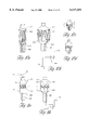
- FIGS. 7A-B show perspective views of another circumferential ablation catheter variation during use in a left atrium according to the method of FIG. 2, wherein FIG. 7A shows a radially compliant expandable member with a working length adjusted to a radially expanded position while in the left atrium, and FIG. 7B shows the expandable member after advancing it into and engaging a pulmonary vein ostium while in the radially expanded position.
- FIG. 7C shows the same perspective view of the left atrium shown in FIGS. 7A-B, although shown after forming a circumferential conduction block according to the circumferential ablation procedure of FIG. 2 and also after removing the circumferential ablation device assembly from the left atrium.
- FIG. 8A diagrammatically shows a method for using the circumferential ablation device assembly of the present invention by forming a circumferential conduction block in a pulmonary vein in combination with a method for forming long linear lesions between pulmonary vein ostia in a less-invasive "maze"-type procedure.
- FIG. 8B shows a perspective view of a segmented left atrium after forming several long linear lesions between adjacent pairs of pulmonary vein ostia according to the method of FIG. 8A.
- FIG. 8C shows a similar perspective view as that shown in FIG. 8B, although showing a circumferential ablation device assembly during use in forming a circumferential lesion in a pulmonary vein which intersects with two linear lesions that extend into the pulmonary vein, according to the method of FIG. 8A.
- FIG. 8D shows a perspective view of another circumferential ablation catheter during use according to the method of FIG. 8A, wherein a circumferential ablation member is provided on an elongate catheter body adjacent to a linear ablation member such that circumferential and linear lesions formed in pulmonary vein wall tissue by the two ablation elements, respectively, intersect.
- FIG. 9 diagrammatically shows a further method for using the circumferential ablation device assembly of the present invention to form a circumferential conduction block in a pulmonary vein wall, wherein signal monitoring and "post-ablation" test elements are used to locate an arrhythmogenic origin along the pulmonary vein wall and to test the efficacy of a circumferential conduction block in the wall, respectively.
- FIGS. 10A-B show perspective views of one circumferential ablation member variation for use in the circumferential ablation device assembly of the present invention, showing a circumferential ablation electrode circumscribing the working length of an expandable member with a secondary shape along the longitudinal axis of the working length which is a modified step shape, the expandable member being shown in a radially collapsed position and also in a radially expanded position, respectively.
- FIGS. 10C-D show perspective views of two circumferential ablation electrodes which form equatorial or otherwise circumferentially placed bands that circumscribe the working length of an expandable member and that have serpentine and sawtooth secondary shapes, respectively, relative to the longitudinal axis of the expandable member when adjusted to a radially expanded position.
- FIGS. 11A-B show perspective views of another circumferential ablation element which includes a plurality of individual ablation electrodes that are spaced circumferentially to form an equatorial band which circumscribes the working length of an expandable member either in an equatorial location. or an otherwise circumferential location that is bounded both proximally and distally by the working length, and which are adapted to form a continuous circumferential lesion while the working length is adjusted to a radially expanded position.
- FIG. 12 shows a cross-sectional view of another circumferential ablation member for use in the circumferential ablation device assembly according to the present invention, wherein the circumferential ablation element circumscribes an outer surface of an expandable member substantially along its working length and is insulated at both the proximal and the distal ends of the working length to thereby form an uninsulated equatorial band in a middle region of the working length or otherwise circumferential region of the working length which is bounded both proximally and distally by end portions of the working length, which member is adapted to ablate a circumferential path of tissue in a pulmonary wall adjacent to the equatorial band.
- FIG. 13 shows a perspective view of another circumferential ablation member which is adapted for use in the circumferential ablation device assembly of the present invention, wherein the expandable member is shown to be a cage of coordinating wires which are adapted to be adjusted from a radially collapsed position to a radially expanded position in order to engage electrode elements on the wires about a circumferential pattern of tissue in a pulmonary vein wall.
- FIG. 14 shows a cross-sectional view of another circumferential ablation element which is adapted for use in the circumferential ablation device assembly of the present invention.
- a superelastic, looped electrode element is shown at the distal end of a pusher and is adapted to circumferentially engage pulmonary vein wall tissue to form a circumferential lesion as a conduction block that circumscribes the pulmonary vein lumen.
- FIG. 15A shows a longitudinal cross-sectional view of another circumferential ablation catheter according to the present invention, and shows the ablation element to include a single cylindrical ultrasound transducer which is positioned along an inner member within an expandable balloon which is further shown in a radially expanded condition.
- FIG. 15B shows a transverse cross-sectional view of the circumferential ablation catheter shown in FIG. 15A taken along line 15B-15B shown in FIG. 15A.
- FIG. 15C shows a transverse cross-sectional view of the circuferential ablation catheter shown in FIG. 15A taken along line 15C-15C shown in FIG. 15A.
- FIG. 15D shows a perspective view of the ultrasonic transducer of FIG. 15A in isolation.
- FIG. 15E shows a modified version of the ultrasonic transducer of FIG. 15D with individually driven sectors.
- FIG. 16A shows a perspective view of a similar circumferential ablation catheter to the catheter shown in FIG. 15, and shows the distal end portion of the circumferential ablation catheter during one mode of use in forming a circumferential conduction block in a pulmonary vein in the region of its ostium along a left atrial wall (shown in cross-section in shadow).
- FIG. 16B shows a similar perspective and cross-section shadow view of a circumferential ablation catheter and pulmonary vein ostium as that shown in FIG. 16A, although shows another circumferential ablation catheter wherein the balloon has a tapered outer diameter.
- FIG. 16C shows a similar view to that shown in FIGS. 16A-B, although showing another circumferential ablation catheter wherein the balloon has a "pear"-shaped outer diameter with a contoured surface along a taper which is adapted to seat in the ostium of a pulmonary vein.
- FIG. 16D shows a cross-sectional view of one circumferential conduction block which may be formed by use of a circumferential ablation catheter such as that shown in FIG. 16C.
- FIG. 17A shows a cross-sectional view of the distal end portion of another circumferential ablation catheter according to the present invention, wherein an outer shield or filter is provided along the balloon's outer surface in order to form a predetermined shape for the circumferential ablation element created by sonic transmissions from the inner ultrasound transducer.
- FIG. 17B shows a similar view as that shown in FIG. 17A, although showing the distal end portion of another circumferential ablation catheter which includes a heat sink as an equatorial band within the circumferential path of energy emission from an inner ultrasound transducer.
- FIG. 18A shows a transverse cross-sectional view of an additional circumferential ablation catheter according to the present invention, and shows the ablation element to include a single transducer sector segment which is positioned along an inner member within an expandable balloon which is further shown in a radially expanded condition.
- FIG. 18B shows a transverse cross-sectional view of an a further circumferential ablation catheter according to the present invention, and shows the ablation element to include a single curvilinear section that is mounted so as to position its concave surface facing in a radially outward direction.
- the present invention is a circumferential ablation device assembly which is adapted to treat patients with atrial arrhythmia by forming a circumferential conduction block in a pulmonary vein which blocks electrical conduction along the longitudinal axis of the pulmonary vein wall and into the left atrium.
- circumference or “circumferential”, including derivatives thereof, are herein intended to mean a continuous path or line which forms an outer border or perimeter that surrounds and thereby defines an enclosed region of space. Such a continuous path starts at one location along the outer border or perimeter, and translates along the outer border or perimeter until it is completed at the original starting location to enclose the defined region of space.
- circumscribe including derivatives thereof, is herein intended to mean to enclose, surround, or encompass a defined region of space.
- a continuous line which is traced around a region of space and which starts and ends at the same location "circumscribes” the region of space and has a “circumference” which is defined by the distance the line travels as it translates along the path circumscribing the space.
- a circumferential path or element may include one or more of several shapes, and may be, for example, circular, oblong, ovular, elliptical, or otherwise planar enclosures.
- a circumferential path may also be three dimensional, such as, for example, two opposite-facing semi-circular paths in two different parallel or off-axis planes which are connected at their ends by line segments bridging between the planes.
- FIGS. 1A-D therefore show various circumferential paths A, B, C, and D, respectively, each translating along a portion of a pulmonary vein wall and circumscribing a defined region of space, shown at a, b, c, and d also respectively, each circumscribed region of space being a portion of a pulmonary vein lumen.
- FIG. 1E shows an exploded perspective view of circumferential path D as it circumscribes multiplanar portions of the pulmonary vein lumen shown at d', d", and d'", which together make up region d as shown in FIG. 1D.
- transect including derivatives thereof, is also herein intended to mean to divide or separate a region of space into isolated regions.
- each of the regions circumscribed by the circumferential paths shown in FIGS. 1A-D transects the respective pulmonary vein, including its lumen and its wall, to the extent that the respective pulmonary vein is divided into a first longitudinal region located on one side of the transecting region, shown, for example, at region "X" in FIG. 1A, and a second longitudinal region on the other side of the transecting plane, shown, for example, at region "Y" also in FIG. 1A.
- a “circumferential conduction block” is formed along a region of tissue which follows a circumferential path along the pulmonary vein wall, circumscribing the pulmonary vein lumen and transecting the pulmonary vein relative to electrical conduction along its longitudinal axis.
- the transecting circumferential conduction block therefore isolates electrical conduction between opposite longitudinal portions of the pulmonary wall relative to the conduction block and along the longitudinal axis.
- ablate or “ablation,” including derivatives thereof, are hereafter intended to mean the substantial altering of the mechanical, electrical, chemical, or other structural nature of tissue.
- ablation is intended to mean sufficient altering of tissue properties to substantially block conduction of electrical signals from or through the ablated cardiac tissue.
- ablation element within the context of "ablation element” is herein intended to mean a discrete element, such as an electrode, or a plurality of discrete elements, such as a plurality of spaced electrodes, which are positioned so as to collectively ablate a region of tissue.
- an "ablation element” may include a variety of specific structures adapted to ablate a defined region of tissue.
- one suitable ablation element for use in the present invention may be formed, according to the teachings of the embodiments below, from an "energy emitting” type which is adapted to emit energy sufficient to ablate tissue when coupled to and energized by an energy source.
- Suitable "energy emitting" ablation elements for use in the present invention may therefore include, for example: an electrode element adapted to couple to a direct current (“DC”) or alternating current (“AC”) current source, such as a radiofrequency (“RF”) current source; an antenna element which is energized by a microwave energy source; a heating element, such as a metallic element or other thermal conductor which is energized to emit heat such as by convective or conductive heat transfer, by resistive heating due to current flow, or by optical heating with light; a light emitting element, such as a fiber optic element which transmits light sufficient to ablate tissue when coupled to a light source; or an ultrasonic element such as an ultrasound crystal element which is adapted to emit ultrasonic sound waves sufficient to ablate tissue when coupled to a suitable excitation source.
- DC direct current
- AC alternating current source
- RF radiofrequency
- ablation elements other elements for altering the nature of tissue may be suitable as "ablation elements" under the present invention when adapted according to the detailed description of the invention below.
- a cryoblation element adapted to sufficiently cool tissue to substantially alter the structure thereof may be suitable if adapted according to the teachings of the current invention.
- a fluid delivery element such as a discrete port or a plurality of ports which are fluidly coupled to a fluid delivery source, may be adapted to infuse an ablating fluid, such as a fluid containing alcohol, into the tissue adjacent to the port or ports to substantially alter the nature of that tissue.
- diagnosis is intended to include patients suspected or predicted to have atrial arrhythmia, in addition to those having specific symptoms or mapped electrical conduction indicative of atrial arrhythmia.
- a patient diagnosed with multiple wavelet arrhythmia originating from multiple regions along the atrial wall is treated in part by forming the circumferential conduction block as an adjunct to forming long linear regions of conduction block between adjacent pulmonary vein ostia in a less-invasive "maze"-type catheter ablation procedure. More detail regarding particular ablation catheter embodiments adapted for use in such a method is provided below with reference to a combination circumferential-long linear lesion ablation device which is described below with reference to FIGS. 8A-D.
- a patient diagnosed with focal arrhythmia originating from an arrhythmogenic origin or focus in a pulmonary vein may also be treated with the circumferential ablation device assembly of the present invention by using the assembly to form a circumferential conduction block along a circumferential path of pulmonary vein wall tissue that either includes the arrhythmogenic origin or is between the origin and the left atrium.
- the arrhythmogenic tissue at the origin is destroyed by the conduction block as it is formed through that focus.
- the arrhythmogenic focus may still conduct abnormally, although such aberrant conduction is prevented from entering and affecting the atrial wall tissue due to the intervening circumferential conduction block.
- FIG. 2 diagrammatically shows the sequential steps of a method for using the circumferential ablation device assembly of the present invention in forming a circumferential conduction block in a pulmonary vein.
- the circumferential ablation method according to FIG. 2 includes: positioning a circumferential ablation element at an ablation region along the pulmonary vein according to a series of detailed steps shown collectively in FIG. 2 as positioning step (3); and thereafter ablating a continuous circumferential region of tissue in the PV wall at the ablation region according to ablation step (4).
- a distal tip of a guiding catheter is first positioned within the left atrium according to a transeptal access method, which is further described in more detail as follows.
- the right venous system is first accessed using the "Seldinger" technique, wherein a peripheral vein (such as a femoral vein) is punctured with a needle, the puncture wound is dilated with a dilator to a size sufficient to accommodate an introducer sheath, and an introducer sheath with at least one hemostatic valve is seated within the dilated puncture wound while maintaining relative hemostasis.
- the guiding catheter or sheath is introduced through the hemostatic valve of the introducer sheath and is advanced along the peripheral vein, into the region of the vena cavae, and into the right atrium.
- the distal tip of the guiding catheter is positioned against the fossa ovalis in the intraatrial septal wall.
- a "Brochenbrough" needle or trocar is then advanced distally through the guide catheter until it punctures the fossa ovalis.
- a separate dilator may also be advanced with the needle through the fossa ovalis to prepare an access port through the septum for seating the guiding catheter.
- the guiding catheter thereafter replaces the needle across the septum and is seated in the left atrium through the fossa ovalis, thereby providing access for object devices through its own inner lumen and into the left atrium.
- left atrial access methods may be suitable substitutes for using the circumferential ablation device assembly of the present invention.
- a "retrograde" approach may be used, wherein the guiding catheter is advanced into the left atrium from the arterial system.
- the Seldinger technique is employed to gain vascular access into the arterial system, rather than the venous, for example, at a femoral artery.
- the guiding catheter is advanced retrogradedly through the aorta, around the aortic arch, into the ventricle, and then into the left atrium through the mitral valve.
- positioning step (3) according to FIG. 2 next includes advancing a guidewire into a pulmonary vein, which is done generally through the guiding catheter seated in the fossa ovalis.
- the guidewire according to this variation may also be advanced into the pulmonary vein by directing it into the vein with a second sub-selective delivery catheter (not shown) which is coaxial within the guiding catheter, such as, for example, by using one of the directional catheters disclosed in U.S. Pat. No. 5,575,766 to Swartz.
- the guidewire may have sufficient stiffness and maneuverability in the left atrial cavity to unitarily subselect the desired pulmonary vein distally of the guiding catheter seated at the fossa ovalis.
- Suitable guidewire designs for use in the overall circumferential ablation device assembly of the present invention may be selected from previously known designs, while generally any suitable choice should include a shaped, radiopaque distal end portion with a relatively stiff, torquable proximal portion adapted to steer the shaped tip under X-ray visualization.
- Guidewires having an outer diameter ranging from 0.010" to 0.035" may be suitable.
- guidewires having an outer diameter ranging from 0.018" to 0.035" may be required. It is believed that guidewires within this size range may be required to provide sufficient stiffness and maneuverability in order to allow for guidewire control and to prevent undesirable guidewire prolapsing within the relatively open atrial cavity.
- positioning step (3) of FIG. 2 next includes tracking the distal end portion of a circumferential ablation device assembly over the guidewire and into the pulmonary vein, followed by positioning a circumferential ablation element at an ablation region of the pulmonary vein where the circumferential conduction block is to be desirably formed.
- FIGS. 3-4 further show a circumferential ablation device assembly (100) according to the present invention during use in performing positioning step (3) and ablation step (4) just described with reference to FIG. 2. Included in the circumferential ablation device assembly (100) are guiding catheter (101), guidewire (102), and circumferential ablation catheter (103).
- FIG. 3 shows guiding catheter (101) subsequent to performing a transeptal access method according to FIG. 2, and also shows guidewire (102) subsequent to advancement and positioning within a pulmonary vein, also according to step (3) of FIG. 2.
- FIG. 3 shows circumferential ablation catheter (103) as it tracks coaxially over guidewire (102) with a distal guidewire tracking member, which is specifically shown only in part at first and second distal guidewire ports (142,144) located on the distal end portion (132) of an elongate catheter body (130).
- a guidewire lumen extends between the first and second distal guidewire ports (142,144) and is adapted to slideably receive and track over the guidewire.
- the second distal guidewire port (142) is located on a distal end portion (132) of the elongate catheter body (130), although proximally of first distal guidewire port (142).
- the distal guidewire tracking member shown in FIG. 3 and just described may be slideably coupled to the guidewire externally of the body in a "backloading" technique after the guidewire is first positioned in the pulmonary vein. Furthermore, there is no need in this guidewire tracking variation for a guidewire lumen in the proximal portions of the elongate catheter body (130), which allows for a reduction in the outer diameter of the catheter shaft in that region. Nevertheless, it is further contemplated that a design which places the second distal guidewire port on the proximal end portion of the elongate catheter body would also be acceptable, as is described below, for example, with reference to the perfusion embodiment of FIG. 5.
- guidewire tracking members which form a bore adapted to slideably receive and track over a guidewire are also considered acceptable, such as, for example, the structure adapted to engage a guidewire as described in U.S. Pat. No. 5,505,702 to Arney, the entirety of which is hereby incorporated by reference herein.
- an alternative circumferential ablation catheter not shown may include a "fixed-wire"-type of design wherein a guidewire is integrated into the ablation catheter as one unit.
- the same type of sub-selective sheaths described above with reference to U.S. Pat. No. 5,575,766 to Swartz for advancing a guidewire into a pulmonary vein may also be used for advancing a circumferential ablation catheter device across the atrium and into a pulmonary vein.
- FIG. 3 also shows circumferential ablation catheter (103) with a circumferential ablation element (160) formed on an expandable member (170).
- the expandable member (170) is shown in FIG. 3 in a radially collapsed position adapted for percutaneous translumenal delivery into the pulmonary vein according to positioning step (3) of FIG. 2.
- expandable member (170) is also adjustable to a radially expanded position when actuated by an expansion actuator (175), as shown in FIG. 4.
- Expansion actuator (175) may include, but is not limited to, a pressurizeable fluid source. According to the expanded state shown in FIG.
- expandable member (170) includes a working length L relative to the longitudinal axis of the elongate catheter body which has a larger expanded outer diameter OD than when in the radially collapsed position. Furthermore, the expanded outer diameter OD is sufficient to circumferentially engage the ablation region of the pulmonary vein.
- working length are herein intended to mean the length of an expandable member which, when in a radially expanded position, has an expanded outer diameter that is: (a) greater than the outer diameter of the expandable member when in a radially collapsed position; and (b) sufficient to engage a body space wall or adjacent ablation region surrounding the expandable member, at least on two opposing internal sides of the body space wall or adjacent ablation region, with sufficient surface area to anchor the expandable member.
- Circumferential ablation element (160) also includes a circumferential band (152) on the outer surface of working length L which is coupled to an ablation actuator (190) at a proximal end portion of the elongate catheter body (shown schematically).
- an ablation actuator 190
- the circumferential band (152) of the circumferential ablation element (160) is actuated by ablation actuator (190) to ablate the surrounding circumferential path of tissue in the pulmonary vein wall, thereby forming a circumferential lesion that circumscribes the pulmonary vein lumen and transects the electrical conductivity of the pulmonary vein to block conduction in a direction along its longitudinal axis.
- FIG. 5A shows another circumferential ablation catheter (203) during use also according to the method of FIG. 2, wherein a perfusion lumen (260) (shown in phantom in FIG. 5B) is formed within the distal end portion (232) of elongate catheter body (230).
- the perfusion lumen (260) in this example is formed between a distal perfusion port, which in this example is the first distal guidewire port (242), and proximal perfusion port (244).
- Proximal perfusion port (244) is formed through the wall of the elongate catheter body (230) and communicates with the guidewire lumen (not shown) which also forms the perfusion lumen between the distal and proximal perfusion ports.
- the guidewire is withdrawn proximally of the proximal perfusion port (244) (shown schematically in shadow) so that the lumen between the ports is clear for antegrade blood flow into the distal perfusion port (242), proximally along the perfusion lumen, out the proximal perfusion port (244) and into the atrium (perfusion flow shown schematically with arrows).
- guidewire (102) is positioned in a guidewire lumen which extends the entire length of the elongate catheter body (230) in an "over-the-wire"-type of design, which facilitates the proximal withdrawal of the guidewire to allow for perfusion while maintaining the ability to subsequently readvance the guidewire distally through the first distal guidewire port (242) for catheter repositioning.
- the guidewire is simply withdrawn and disengaged from the second distal guidewire port (244), in which case the circumferential ablation catheter must generally be withdrawn from the body in order to recouple the distal guidewire tracking member with the guidewire.
- a proximal perfusion port is provided as a separate and distinct port positioned between the second distal guidewire port (244) and the expandable member (270), which allows for proximal withdrawal of the guidewire to clear the guidewire lumen and thereby form a perfusion lumen between the first distal guidewire port and the proximal perfusion port.
- the guidewire of this alternative variation however, remains engaged within the guidewire lumen between the second distal guidewire port and the proximal perfusion port.
- the expandable member when in the radially expanded position during ablation blocks the flow from the vein into the atrium, which flow stasis may result in undesirable thrombogenesis in the pulmonary vein distally to the expandable member.
- the perfusion feature according to the variation of FIGS. 5A-B may also provide a cooling function in the surrounding region, including in the blood adjacent to the expandable member.
- FIG. 6 shows pulmonary vein (52) after removing the circumferential ablation device assembly subsequent to forming a circumferential lesion (70) around the ablation region of the pulmonary vein wall (53) according to the use of the circumferential ablation device assembly shown in stepwise fashion in FIGS. 3-6.
- Circumferential lesion (70) is shown located along the pulmonary vein adjacent to the pulmonary vein ostium (54), and is shown to also be “transmural,” which is herein intended to mean extending completely through the wall, from one side to the other.
- the circumferential lesion (70) is shown in FIG. 6 to form a "continuous" circumferential band, which is herein intended to mean without gaps around the pulmonary vein wall circumference, thereby circumscribing the pulmonary vein lumen.
- circumferential catheter ablation with a circumferential ablation element according to the present invention may leave some tissue, either transmurally or along the circumference of the lesion, which is not actually ablated, but which is not substantial enough to allow for the passage of conductive signals. Therefore, the terms "transmural” and “continuous” as just defined are intended to have functional limitations, wherein some tissue in the ablation region may be unablated but there are no functional gaps which allow for symptomatically arrhythmogenic signals to conduct through the conduction block and into the atrium from the pulmonary vein.
- FIGS. 7A-B show a further variation of the present invention, wherein a circumferential ablation member (350) includes a radially compliant expandable member (370) which is adapted to conform to a pulmonary vein ostium (54) at least in part by adjusting it to a radially expanded position while in the left atrium and then advancing it into the ostium.
- FIG. 7A shows expandable member (370) after being adjusted to a radially expanded position while located in the left atrium (50).
- FIG. 7B further shows expandable member (370) after being advanced into the pulmonary vein (52) until at least a portion of the expanded working length L of circumferential ablation member (350), which includes a circumferential band (352), engages the pulmonary vein ostium (54).
- FIG. 7C shows a portion of a circumferential lesion (72) which forms a circumferential conduction block in the region of the pulmonary vein ostium (54) subsequent to actuating the circumferential ablation element to form the circumferential lesion.
- FIGS. 8A-D collectively show a circumferential ablation device assembly according to the present invention as it is used to form a circumferential conduction block adjunctively to the formation of long linear lesions in a less-invasive "maze"-type procedure, as introduced above for the treatment of multiwavelet reentrant type fibrillation along the left atrial wall.
- FIG. 8A diagrammatically shows a summary of steps for performing a "maze"-type procedure by forming circumferential conduction blocks that intersect with long linear conduction blocks formed between the pulmonary veins.
- a box-like conduction block surrounding an arrhythmogenic atrial wall region bounded by the pulmonary veins may be created by forming long linear lesions between anchors in all pairs of adjacent pulmonary vein ostia, such as is shown in part in steps (5) and (6) of FIG. 8A.
- linear lesions may be made sufficiently narrow with respect to the surface area of the pulmonary vein ostia that they may not intersect, thereby leaving gaps between them which may present proarrhythmic pathways for abnormal conduction into and from the box, such as is shown between linear lesions (57,58) in FIG. 8B. Therefore, by forming the circumferential conduction block according to step (7) of FIG. 8A, and as shown by use of circumferential ablation member (450) in FIG. 8C, the linear lesions are thereby bridged and the gaps are closed.
- FIG. 8D shows a circumferential ablation device assembly which includes both circumferential and linear ablation elements (452,460), respectively.
- Circumferential ablation member (450) is shown to include an expandable member (470) which is adjusted to a radially expanded position that is asymmetric to the underlying catheter shaft.
- Linear ablation member (460) extends along the elongate body proximally from the circumferential ablation member (450). When expanded sufficiently to engage the pulmonary vein wall, expandable member (470) provides at least a portion of an anchor for a first end (462) of linear ablation member (460).
- a shaped stylet (466) is shown in shadow in FIG. 8D within the elongate catheter body in the region of the second end (464) of the linear ablation member (460).
- Shaped stylet (466) includes a port or opening (465) though which guidewire (469) passes in order to anchor the second end (464) into an adjacent pulmonary vein ostium such that the linear ablation member (460) is adapted to substantially contact the left atrial wall between the adjacent vein ostia to form the linear ablation according to the method of FIG. 8A.
- a second anchor may effected with, for example, an intermediate guidewire tracking member adapted to track over a guidewire (469) engaged to the pulmonary vein.
- FIG. 9 diagrammatically shows a further method for using the circumferential ablation device assembly of the present invention wherein electrical signals along the pulmonary vein are monitored with a sensing element before and after ablation according to steps (8) and (9), respectively. Signals within the pulmonary vein are monitored prior to forming a conduction block, as indicated in step (8) in FIG. 9, in order to confirm that the pulmonary vein chosen contains an arrhythmogenic origin for atrial arrhythmia. Failure to confirm an arrhythmogenic origin in the pulmonary vein, particularly in the case of a patient diagnosed with focal arrhythmia, may dictate the need to monitor signals in another pulmonary vein in order to direct treatment to the proper location in the heart.
- monitoring the pre-ablation signals may be used to indicate the location of the arrhythmogenic origin of the atrial arrhythmia, which information helps determine the best location to form the conduction block.
- the conduction block may be positioned to include and therefore ablate the actual focal origin of the arrhythmia, or may be positioned between the focus and the atrium in order to block aberrant conduction from the focal origin and into the atrial wall.
- electrical signals along the pulmonary vein wall may also be monitored by the sensing element subsequent to circumferential ablation, according to step (9) of the method of FIG. 9.
- This monitoring method aids in testing the efficacy of the ablation in forming a complete conduction block against arrhythmogenic conduction.
- Arrhythmogenic firing from the identified focus will not be observed during signal monitoring along the pulmonary vein wall when taken below a continuous circumferential and transmural lesion formation, and thus would characterize a successful circumferential conduction block.
- test electrode may also be used in a "post ablation" signal monitoring method according to step (10) of FIG. 9.
- the test electrode is positioned on the distal end portion of an elongate catheter body and is electrically coupled to a current source for firing a test signal into the tissue surrounding the test electrode when it is placed distally or "upstream" of the circumferential lesion in an attempt to simulate a focal arrhythmia.
- This test signal generally challenges the robustness of the circumferential lesion in preventing atrial arrhythmia from any such future physiologically generated aberrant activity along the suspect vein.
- such methods may be performed with a separate electrode or electrode pair located on the catheter distal end portion adjacent to the region of the circumferential ablation element, or may be performed using one or more electrodes which form the circumferential ablation element itself, as will be further developed below.
- the circumferential ablation members shown in the previous figures do illustrate one particular embodiment wherein a circumferential electrode element circumscribes an outer surface of an expandable member.
- the expandable member of the embodiments shown may take one of several different forms, although the expandable member is generally herein shown as an inflatable balloon that is coupled to an expansion actuator (175) which is a pressurizeable fluid source.
- the balloon is preferably made of a polymeric material and forms a fluid chamber which communicates with a fluid passageway (not shown in the figures) that extends proximally along the elongate catheter body and terminates proximally in a proximal fluid port that is adapted to couple to the pressurizeable fluid source.
- the balloon is constructed of a relatively inelastic polymer such as a polyethylene (“PE”; preferably linear low density or high density or blends thereof), polyolefin copolymer (“POC”), polyethylene terepthalate (“PET”), polyimide, or a nylon material.
- PE polyethylene
- POC polyolefin copolymer
- PET polyethylene terepthalate
- the balloon has a low radial yield or compliance over a working range of pressures and may be folded into a predetermined configuration when deflated in order to facilitate introduction of the balloon into the desired ablation location via known percutaneous catheterization techniques.
- one balloon size may not suitably engage all pulmonary vein walls for performing the circumferential ablation methods of the present invention on all needy patients. Therefore, it is further contemplated that a kit of multiple ablation catheters, with each balloon working length having a unique predetermined expanded diameter, may be provided from which a treating physician may chose a particular device to meet a particular patient's pulmonary vein anatomy
- the balloon is constructed of a relatively compliant, elastomeric material, such as, for example (but not limited to), a silicone, latex, or mylar elastomer.
- the balloon takes the form of a tubular member in the deflated, non-expanded state.
- fluid such as in the previous, relatively non-compliant example
- the material forming the wall of the tubular member elastically deforms and stretches radially to a predetermined diameter for a given inflation pressure.
- the compliant balloon may be constructed as a composite, such as, for example, a latex or silicone balloon skin which includes fibers, such as metal, Kevlar, or nylon fibers, which are embedded into the skin.
- fibers such as metal, Kevlar, or nylon fibers, which are embedded into the skin.
- Such fibers when provided in a predetermined pattern such as a mesh or braid, may provide a controlled compliance along a preferred axis, preferably limiting longitudinal compliance of the expandable member while allowing for radial compliance.
- the relatively compliant variation may provide a wide range of working diameters, which may allow for a wide variety of patients, or of vessels within a single patient, to be treated with just one or a few devices. Furthermore, this range of diameters is achievable over a relatively low range of pressures, which is believed to diminish a potentially traumatic vessel response that may otherwise be presented concomitant with higher pressure inflations, particularly when the inflated balloon is oversized to the vessel.
- the low-pressure inflation feature of this variation is suitable for the present invention because the functional requirement of the expandable balloon is merely to engage the ablation element against a circumferential path along the inner lining of the pulmonary vein wall.
- a circumferential ablation member is adapted to conform to the geometry of the pulmonary vein ostium, at least in part by providing substantial compliance to the expandable member, as was shown and described previously by reference to FIGS. 7A-B.
- the working length L of expandable member (370) is also shown to include a taper which has a distally reducing outer diameter from a proximal end (372) to a distal end (374).
- ablation actuator generally includes a radio-frequency ("RF") current source (not shown) that is coupled to both the RF electrode element and also a ground patch (195) which is in skin contact with the patient to complete an RF circuit.
- RF radio-frequency
- ablation actuator (190) preferably includes a monitoring circuit (not shown) and a control circuit (not shown) which together use either the electrical parameters of the RF circuit or tissue parameters such as temperature in a feedback control loop to drive current through the electrode element during ablation. Also, where a plurality of ablation elements or electrodes in one ablation element are used, a switching means may be used to multiplex the RF current source between the various elements or electrodes.
- FIGS. 10A-D show various patterns of electrically conductive, circumferential electrode bands as electrode ablation elements, each circumscribing an outer surface of the working length of an expandable member.
- FIGS. 10A-B show circumferential ablation member (550) to include a continuous circumferential electrode band (552) that circumscribes an outer surface of an expandable member (570).
- FIG. 10B more specifically shows expandable member (570) as a balloon which is fluidly coupled to a pressurizeable fluid source (175), and further shows electrode band (circumferential ablation element) (552) electrically coupled via electrically conductive lead (554) to ablation actuator (190).
- apertures (572) are shown in the balloon skin wall of expandable member (570) adjacent to electrode band (552).
- the purpose of these apertures (572) is to provide a positive flow of fluid such as saline or ringers lactate fluid into the tissue surrounding the electrode band (552). Such fluid flow is believed to reduce the temperature rise in the tissue surrounding the electrode element during RF ablation.
- FIGS. 10A-D allow for a continuous electrode band to circumscribe an expandable member's working length over a range of expanded diameters, a feature which is believed to be particularly useful with a relatively compliant balloon as the expandable member.
- this feature is provided primarily by a secondary shape given to the electrode band relative to the longitudinal axis of the working length of the expandable member.
- Electrode band (552) is thus shown in FIGS. 10A-B to take the specific secondary shape of a modified step curve.
- Other shapes than a modified step curve are also suitable, such as the serpentine or sawtooth secondary shapes shown respectively in FIGS. 10C-D.
- Other shapes in addition to those shown in FIGS. 10A-D and which meet the defined functional requirements are further contemplated within the scope of the present invention.
- the electrode band provided by the circumferential ablation elements shown in FIGS. 10C-D and also shown schematically in FIGS. 3-5 has a functional band width w relative to the longitudinal axis of the working length which is only required to be sufficiently wide to form a complete conduction block against conduction along the walls of the pulmonary vein in directions parallel to the longitudinal axis.
- the working length L of the respective expandable element is adapted to securely anchor the distal end portion in place such that the ablation element is firmly positioned at a selected region of the pulmonary vein for ablation.
- the band width w is relatively narrow compared to the working length L of the expandable element, and the electrode band may thus form a relatively narrow equatorial band which has a band width that is less than two-thirds or even one-half of the working length of the expandable element.
- a narrow band may be placed at locations other than the equator of the expandable element, preferably as long as the band is bordered on both sides by a portion of the working length L.
- the circumferential lesion formed may also be relatively narrow when compared to its own circumference, and may be less than two-thirds or even one-half its own circumference on the expandable element when expanded.
- the band width w is less than 1 cm with a circumference on the working length when expanded that is greater than 1.5 cm.
- FIGS. 11A-B show a further variation of a circumferential ablation element which is adapted to maintain a continuous circumferential lesion pattern over a range of expanded diameters and which includes electrode elements that form a relatively narrow equatorial band around the working length of an expandable balloon member.
- a plurality of individual electrode/ablation elements are included in the circumferential ablation element and are positioned in spaced arrangement along an equatorial band which circumscribes an outer surface of the expandable member's working length L.
- Each individual electrode element (562) has two opposite ends (563,564), respectively, along a long axis LA and also has a short axis SA, and is positioned such that the long axis LA is at an acute angle relative to the longitudinal axis La of the elongate catheter body and expandable member (560).
- At least one of the ends (563,564) along the long axis LA overlaps with an end of another adjacent individual electrode element, such that there is a region of overlap along their circumferential aspect, i.e., there is a region of overlap along the circumferential coordinates.
- region of overlap along their circumferential coordinate are herein intended to mean that the two adjacent ends each are positioned along the working length with a circumferential and also a longitudinal coordinate, wherein they share a common circumferential coordinate.
- the circumferential compliance along the working length which accompanies radial expansion of the expandable member also moves the individual electrode elements apart along the circumferential axis.
- the spaced, overlapping arrangement described allows the individual ablation elements to maintain a certain degree of their circumferential overlap, or at least remain close enough together, such that a continuous lesion may be formed without gaps between the elements.
- suitable circumferential electrode elements in the RF variation of the present invention may comprise a metallic material deposited on the outer surface of the working length using conventional techniques, such as by plasma depositing, sputter coating, chemical vapor deposition, other known techniques which are equivalent for this purpose, or otherwise affixing a metallic shaped member onto the outer surface of the expandable member such as through known adhesive bonding techniques.
- Other RF electrode arrangements are also considered within the scope of the present invention, so long as they form a circumferential conduction block as previously described.
- a balloon skin may itself be metallized, such as by mixing conductive metal, including but not limited to gold, platinum, or silver, with a polymer to form a compounded, conductive matrix as the balloon skin.
- another circumferential ablation member variation may also include an expandable member, such as an inflatable balloon, that includes a porous skin that is adapted to allow fluid, such as hypertonic saline solution, to pass from an internal chamber defined by the skin and outwardly into surrounding tissues.
- an expandable member such as an inflatable balloon
- a porous skin that is adapted to allow fluid, such as hypertonic saline solution, to pass from an internal chamber defined by the skin and outwardly into surrounding tissues.
- a porous skin may be constructed according to several different methods, such as by forming holes in an otherwise contiguous polymeric material, including mechanically drilling or using laser energy, or the porous skin may simply be an inherently porous membrane.
- the porous region of the expandable member serves as an RF electrode wherein RF current flows outwardly through the pores via the conductive fluid.
- a porous outer skin may be provided externally of another, separate expandable member, such as a separate expandable balloon, wherein the conductive fluid is contained in a region between the porous outer skin and the expandable member contained therein.
- Various other "fluid electrode" designs may also be suitable according to one of ordinary skill upon review of this disclosure.
- the circumferential ablation element may also include other ablative energy sources or sinks, and particularly may include a thermal conductor that circumscribes the outer circumference of the working length of an expandable member.
- suitable thermal conductor arrangements include a metallic element which may, for example, be constructed as previously described for the more detailed RF embodiments above. However, in the thermal conductor embodiment such a metallic element would be generally either resistively heated in a closed loop circuit internal to the catheter, or conductively heated by a heat source coupled to the thermal conductor.
- the expandable member may be, for example, a polymeric balloon skin which is inflated with a fluid that is heated either by a resistive coil or by bipolar RF current.
- a thermal conductor on the outer surface of the expandable member is suitable when it is adapted to heat tissue adjacent thereto to a temperature between 40 deg and 80 deg Celsius.
- the perfusion balloon embodiment as shown in FIGS. 5A-B may be particularly useful in such a design. It is believed that ablation through increased temperatures, as provided by example above may also enhance coagulation of blood in the pulmonary vein adjacent to the expandable member, which blood would otherwise remain stagnant without such a perfusion feature.
- FIG. 12 One further circumferential ablation element design which is believed to be highly useful in performing the methods according to the present invention is shown in FIG. 12 to include a circumferential ablation member (600) with two insulators (602,604) that encapsulate the proximal and distal ends, respectively, of the working length L of an expandable member (610).
- the insulators (602,604) are thermal insulators, such as a thermal insulator comprising a Teflon material.
- Expandable member (610) is an inflatable balloon which has a balloon skin (612) that is thermally conductive to surrounding tissue when inflated with a heated fluid which may contain a radiopaque agent, saline fluid, ringers lactate, combinations thereof, other known biocompatible fluids having acceptable heat transfer properties for these purposes, further to the thermal conductor embodiments previously described.
- a circumferential ablation element is formed as an equatorial band (603) of uninsulated balloon skin is located between the opposite insulators.
- the circumferential ablation element is able to conduct heat externally of the balloon skin much more efficiently at the uninsulated equatorial band (603) than at the insulated portions, and thereby is adapted to ablate only a circumferential region of tissue in a pulmonary vein wall which is adjacent to the equatorial band.
- this embodiment is not limited to an "equatorial" placement of the ablation element. Rather, a circumferential band may be formed anywhere along the working length of the expandable member and circumscribing the longitudinal axis of the expandable member as previously described.
- FIG. 12 further shows use of a radiopaque marker (620) to identify the location of the equatorial band (603) in order to facilitate placement of that band at a selected ablation region of a pulmonary vein via X-ray visualization.
- Radiopaque marker (620) is opaque under X-ray, and may be constructed, for example, of a radiopaque metal such as gold, platinum, or tungsten, or may comprise a radiopaque polymer such as a metal loaded polymer.
- FIG. 12 shows radiopaque marker (620) positioned coaxially over an inner tubular member (621) which is included in a coaxial catheter design as would be apparent to one of ordinary skill.
- the present invention contemplates the combination of such a radiopaque marker additionally in the other embodiments herein shown and described.
- a radiopaque marker additionally in the other embodiments herein shown and described.
- the circumferential ablation member which forms an equatorial band includes a metallic electrode element
- such electrode may itself be radiopaque and may not require use of a separate marker as just described.
- the thermal insulator embodiment just described by reference to FIG. 12 is illustrative of a broader embodiment, wherein a circumferential ablation member has an ablating surface along the entire working length of an expandable member, but is shielded from releasing ablative energy into surrounding tissues except for along an unshielded or uninsulated equatorial band.
- the insulator embodiment contemplates other ablation elements, such as the RF embodiments previously described above, which are provided along the entire working length of an expandable member and which are insulated at their ends to selectively ablate tissue only about an uninsulated equatorial band.
- a metallized balloon which includes a conductive balloon skin may have an electrical insulator, such as a polymeric coating, at each end of the working length and thereby selectively ablate tissue with electricity flowing through the uninsulated equatorial band.
- an electrical insulator such as a polymeric coating
- the insulators described may be only partial and still provide the equatorial band result. For instance, in the conductive RF electrode balloon case, a partial electrical insulator will allow a substantial component of current to flow through the uninsulated portion due to a "shorting" response to the lower resistance in that region.
- a porous membrane comprises the entire balloon skin of an expandable member.
- cage (650) comprises coordinating wires (651) and is expandable to engage a desired ablation region in a pulmonary vein.
- cage (650) The radial expansion of cage (650) is accomplished as follows. Sheath (652) is secured around the wires proximally of cage (650). However, core (653), which may be a metallic mandrel such as stainless steel, extends through sheath (652) and distally within cage (650) wherein it terminates in a distal tip (656). Wires (651) are secured to distal tip (656), for example, by soldering, welding, adhesive bonding, heat shrinking a polymeric member over the wires, or any combination of these methods.
- core (653) which may be a metallic mandrel such as stainless steel
- Core (653) is slideable within sheath (652), and may, for example, be housed within a tubular lumen (not shown) within sheath (652), the wires being housed between a coaxial space between the tubular lumen and sheath (652).
- the cage (650) is collapsible along its longitudinal axis in order to force an outward radial bias (also shown with arrows in FIG. 13) to wires (651) in an organized fashion to formed a working length of cage (650) which is expanded (not shown).
- a plurality of ablation electrodes (655) is shown, each being positioned on one of wires (651) and being similarly located along the longitudinal axis of the cage (650).
- the radial bias given to wires (651) during expansion, together with the location of the ablation electrodes (655), serves to position the plurality of ablation electrodes/elements (655) along a circumferential, equatorial band along the expanded working length of cage (650).
- the wires forming a cage according to this embodiment may also have another predetermined shape when in the radially expanded position.
- a taper similar to that shown for expandable member (370) in FIGS. 7A-B may be formed by expanding cage (650), wherein the ablation element formed by ablation electrodes (655) may be positioned between the proximal end and the distal end of the taper.
- wires (651) are preferably metal, and may comprise stainless steel or a superelastic metal alloy, such as an alloy of nickel and titanium, or a combination of both.
- a separate electrical conductor may be required in order to actuate ablation electrodes (655) to efficiently emit ablative current into surrounding tissues.
- wires (651) are constructed of stainless steel, they may also serve as electrical conductors for ablation electrodes (655).
- the wires (651) may be coated with an electrical insulator to isolate the electrical flow into surrounding tissues at the site of the ablation electrodes (655).
- the ablation electrodes (655) in the stainless steel wire variation may be formed simply by removing electrical insulation in an isolated region to allow for current to flow into tissue only from that exposed region.
- a circumferential strip of electrodes may also be secured to the cage (650) such that the strip circumscribes the cage at a predetermined location along the cage's longitudinal axis.
- the strip of electrodes are adapted to take a circumferential shape according to the shape of the expanded cage (650).
- Such an electrode strip is preferably flexible, such that it may be easily reconfigured when the cage is adjusted between the radially collapsed and expanded positions and such that the strip may be easily advanced and withdrawn with the cage within the delivery sheath.
- the electrode strip may be a continuous circumferential electrode such as a conductive spring coil, or may be a flexible strip which includes several separate electrodes along its circumferential length. In the latter case, the flexible strip may electrically couple all of the electrodes to a conductive lead that interfaces with a drive circuit, or each electrode may be separately coupled to one or more such conductive leads.
- circumferential ablation member (700) includes a looped member (710) attached, preferably by heat shrinking, to a distal end of a pusher (730).
- Looped member (710) and pusher (730) are slideably engaged within delivery sheath (750) such that looped member (710) is in a first collapsed position when positioned and radially confined within delivery sheath (750), and expands to a second expanded position when advanced distally from delivery sheath (750).
- Looped member (710) is shown in more detail in FIG. 14 to include a core (712) which is constructed of a superelastic metal alloy such as a nickel-titanium alloy and which has a looped portion with shape memory in the looped configuration.
- This looped configuration is shown in FIG. 14 to be in a plane which is off-axis, preferably perpendicular, to the longitudinal axis of the pusher (730).
- This off-axis orientation of the loop is adapted to engage a circumferential path of tissue along a pulmonary vein wall which circumscribes the pulmonary vein lumen when the looped member (710) is delivered from the delivery sheath (750) when the delivery sheath is positioned within the vein lumen parallel to its longitudinal axis.
- An ablation electrode (714) is also shown in FIG. 14 as a metallic coil which is wrapped around core (712) in its looped portion.
- Pusher (730) is further shown in FIG. 14 to include a tubular pusher member (732) which is heat shrunk over two ends (712') of core (712) which extend proximally of looped member (710) through pusher (730) in the particular variation shown. While in this embodiment core (712) extends through the pusher in order to provide stiffness to the composite design for the pusher, it is further contemplated that the superelastic metal of the core may be replaced or augmented in the pusher region with another different mandrel or pusher core (not shown), such as a stiffer stainless steel mandrel.
- an electrically conductive lead (735) which is coupled to the ablation electrode (714) and which is also adapted in a proximal region of the pusher (not shown) to couple to an ablation actuator (190) such as an RF current source (shown schematically).
- FIGS. 15A-18B show various specific embodiments of a broader circumferential ablation device assembly which utilizes an ultrasonic energy source to ablate tissue.
- the present circumferential ablation device has particular utility in connection with forming a circumferential lesion within or about a pulmonary vein ostium or within the vein itself in order to form a circumferential conductive block.
- This application of the present ablation device is merely exemplary, and it is understood that those skilled in the art can readily adapt the present ablation device for applications in other body spaces.
- a source of acoustic energy is provided a delivery device that also includes an anchoring mechanism.
- the anchoring device comprises an expandable member that also positions the acoustic energy source within the body; however, other anchoring and positioning devices may also be used, such as, for example, a basket mechanism.
- the acoustic energy source is located within the expandable member and the expandable member is adapted to engage a circumferential path of tissue either about or along a pulmonary vein in the region of its ostium along a left atrial wall.
- the acoustic energy source in turn is acoustically coupled to the wall of the expandable member and thus to the circumferential region of tissue engaged by the expandable member wall by emitting a circumferential and longitudinally collimated ultrasound signal when actuated by an acoustic energy driver.
- acoustic energy, and particularly ultrasonic energy offers the advantage of simultaneously applying a dose of energy sufficient to ablate a relatively large surface area within or near the heart to a desired heating depth without exposing the heart to a large amount of current.
- a collimated ultrasonic transducer can form a lesion, which has about a 1.5 mm width, about a 2.5 cm diameter lumen, such as a pulmonary vein and of a sufficient depth to form an effective conductive block. It is believed that an effective conductive block can be formed by producing a lesion within the tissue that is transmural or substantially transmural. Depending upon the patient as well as the location within the pulmonary vein ostium, the lesion may have a depth of 1 millimeter to 10 millimeters. It has been observed that the collimated ultrasonic transducer can be powered to provide a lesion having these parameters so as to form an effective conductive block between the pulmonary vein and the posterior wall of the left atrium.
- a circumferential ablation device assembly (800) includes an elongate body (802) with proximal and distal end portions (810,812), an expandable balloon (820) located along the distal end portion (812) of elongate body (802), and a circumferential ultrasound transducer (830) which forms a circumferential ablation member which is acoustically coupled to the expandable balloon (820).
- FIGS. 15A-C variously show elongate body (802) to include guidewire lumen (804), inflation lumen (806), and electrical lead lumen (808).
- the ablation device can be of a self steering type rather than an over-the-wire type device.
- Each lumen extends between a proximal port (not shown) and a respective distal port, which distal ports are shown as distal guidewire port (805) for guidewire lumen (804), distal inflation port (807) for inflation lumen (806), and distal lead port (809) for electrical lead lumen (808).
- distal guidewire port (805) for guidewire lumen (804)
- distal inflation port (807) for inflation lumen (806)
- distal lead port (809) for electrical lead lumen (808) for electrical lead lumen (808.
- the guidewire, inflation and electrical lead lumens are generally arranged in a side-by-side relationship
- the elongate body (802) can be constructed with one or more of these lumens arranged in a coaxial relationship, or in any of a wide variety of configurations that will be readily apparent to one of ordinary skill in the art.
- the elongate body (802) is also shown in FIGS. 15A and 15C to include an inner member (803) which extends distally beyond distal inflation and lead ports (807,809), through an interior chamber formed by the expandable balloon (820), and distally beyond expandable balloon (820) where the elongate body terminates in a distal tip.
- the inner member (803) forms the distal region for the guidewire lumen (804) beyond the inflation and lead ports, and also provides a support member for the cylindrical ultrasound transducer (830) and for the distal neck of the expansion balloon, as described in more detail below.
- the elongate body (802) itself may have an outer diameter provided within the range of from about 5 French to about 10 French, and more preferable from about 7 French to about 9 French.
- the guidewire lumen preferably is adapted to slideably receive guidewires ranging from about 0.010 inch to about 0.038 inch in diameter, and preferably is adapted for use with guidewires ranging from about 0.018 inch to about 0.035 inch in diameter. Where a 0.035 inch guidewire is to be used, the guidewire lumen preferably has an inner diameter of 0.040 inch to about 0.042 inch.
- the inflation lumen preferably has an inner diameter of about 0.020 inch in order to allow for rapid deflation times, although may vary based upon the viscosity of inflation medium used, length of the lumen, and other dynamic factors relating to fluid flow and pressure.
- the elongate body (802) of the present embodiment must also be adapted to be introduced into the left atrium such that the distal end portion with balloon and transducer may be placed within the pulmonary vein ostium in a percutaneous translumenal procedure, and even more preferably in a transeptal procedure as otherwise herein provided. Therefore, the distal end portion (812) is preferably flexible and adapted to track over and along a guidewire seated within the targeted pulmonary vein. In one further more detailed construction which is believed to be suitable, the proximal end portion is adapted to be at least 30% more stiff than the distal end portion.
- the proximal end portion may be suitably adapted to provide push transmission to the distal end portion while the distal end portion is suitably adapted to track through bending anatomy during in vivo delivery of the distal end portion of the device into the desired ablation region.
- FIG. 15A variation is shown as an "over-the-wire" catheter construction
- other guidewire tracking designs may be suitable substitutes, such as, for example, catheter devices which are known as “rapid exchange” or “monorail” variations wherein the guidewire is only housed coaxially within a lumen of the catheter in the distal regions of the catheter.
- a deflectable tip design may also be a suitable substitute and which is adapted to independently select a desired pulmonary vein and direct the transducer assembly into the desired location for ablation.
- acceptable pullwires may have a diameter within the range from about 0.008 inch to about 0.020 inch, and may further include a taper, such as, for example, a tapered outer diameter from about 0.020 inch to about 0.008 inch.
- a central region (822) is generally coaxially disposed over the inner member (803) and is bordered at its end neck regions by proximal and distal adaptions (824,826).
- the proximal adaption (824) is sealed over elongate body (802) proximally of the distal inflation and the electrical lead ports (807,809), and the distal adaption (826) is sealed over inner member (803).
- a fluid tight interior chamber is formed within expandable balloon (820). This interior chamber is fluidly coupled to a pressurizeable fluid source (not shown) via inflation lumen (806).
- electrical lead lumen (808) also communicates with the interior chamber of expandable balloon (820) so that the ultrasound transducer (830), which is positioned within that chamber and over the inner member (803), may be electrically coupled to an ultrasound drive source or actuator, as will be provided in more detail below.
- the expandable balloon (820) may be constructed from a variety of known materials, although the balloon (820) preferably is adapted to conform to the contour of a pulmonary vein ostium.
- the balloon material can be of the highly compliant variety, such that the material elongates upon application of pressure and takes on the shape of the body lumen or space when fully inflated.
- Suitable balloon materials include elastomers, such as, for example, but without limitation, Silicone, latex, or low durometer polyurethane (for example, a durometer of about 80A).
- the balloon (820) can be formed to have a predefined fully inflated shape (i.e., be preshaped) to generally match the anatomic shape of the body lumen in which the balloon is inflated.
- the balloon can have a distally tapering shape to generally match the shape of a pulmonary vein ostium, and/or can include a bulbous proximal end to generally match a transition region of the atrium posterior wall adjacent to the pulmonary vein ostium. In this manner, the desired seating within the irregular geometry of a pulmonary vein or vein ostium can be achieved with both compliant and non-compliant balloon variations.
- the balloon (820) is preferably constructed to exhibit at least 300% expansion at 3 atmospheres of pressure, and more preferably to exhibit at least 400% expansion at that pressure.
- the term “expansion” is herein intended to mean the balloon outer diameter after pressurization divided by the balloon inner diameter before pressurization, wherein the balloon inner diameter before pressurization is taken after the balloon is substantially filled with fluid in a taught configuration.
- “expansion” is herein intended to relate to change in diameter that is attributable to the material compliance in a stress strain relationship.
- the balloon is adapted to expand under a normal range of pressure such that its outer diameter may be adjusted from a radially collapsed position of about 5 millimeters to a radially expanded position of about 2.5 centimeters (or approximately 500% expansion ratio).
- the ablation member which is illustrated in FIGS. 15A-D, takes the form of annular ultrasonic transducer (830).
- the annular ultrasonic transducer has a unitary cylindrical shape with a hollow interior (i.e., is tubular shaped); however, the transducer applicator (830) can have a generally annular shape and be formed of a plurality of segments.
- the transducer applicator (830) can be formed by a plurality of tube sectors that together form an annular shape.
- the tube sectors can also be of sufficient arc lengths so as when joined together, the sectors assembly forms a "clover-leaf" shape. This shape is believed to provide overlap in heated regions between adjacent elements.
- the generally annular shape can also be formed by a plurality of planar transducer segments which are arranged in a polygon shape (e.g., hexagon).
- a polygon shape e.g., hexagon
- the transducer applicator can be formed of a multi-element array, as described in greater detail below.
- cylindrical ultrasound transducer (830) includes a tubular wall (831) which includes three concentric tubular layers.
- the central layer (832) is a tubular shaped member of a piezoceramic or piezoelectric crystalline material.
- the transducer preferably is made of type PZT-4, PZT-5 or PZT-8, quartz or Lithium-Niobate type piezoceramic material to ensure high power output capabilities.
- These types of transducer materials are commercially available from Stavely Sensors, Inc. of East Hartford, Conn., or from Valpey-Fischer Corp. of Hopkinton, Mass.
- the outer and inner tubular members (833,834) enclose central layer (832) within their coaxial space and are constructed of an electrically conductive material.
- these transducer electrodes (833, 834) comprise a metallic coating, and more preferably a coating of nickel, copper, silver, gold, platinum, or alloys of these metals.
- the length of the transducer (830) or transducer assembly desirably is selected for a given clinical application.
- the transducer length can fall within the range of approximately 2 mm up to greater than 10 mm, and preferably equals about 5 mm to 10 mm.
- a transducer accordingly sized is believed to form a lesion of a width sufficient to ensure the integrity of the formed conductive block without undue tissue ablation. For other applications, however, the length can be significantly longer.
- the transducer outer diameter desirably is selected to account for delivery through a particular access path (e.g., percutaneously and transeptally), for proper placement and location within a particular body space, and for achieving a desired ablation effect.
- the transducer (830) preferably has an outer diameter within the range of about 1.8 mm to greater than 2.5 mm. It has been observed that a transducer with an outer diameter of about 2 mm generates acoustic power levels approaching 20 Watts per centimeter radiator or greater within myocardial or vascular tissue, which is believed to be sufficient for ablation of tissue engaged by the outer balloon for up to about 2 cm outer diameter of the balloon.
- the transducer applicator (830) may have an outer diameter within the range of about 1 mm to greater than 3-4 mm (e.g., as large as 1 to 2 cm for applications in some body spaces).
- the central layer (832) of the transducer (830) has a thickness selected to produce a desired operating frequency.
- the operating frequency will vary of course depending upon clinical needs, such as the tolerable outer diameter of the ablation and the depth of heating, as well as upon the size of the transducer as limited by the delivery path and the size of the target site.
- the transducer (830) in the illustrated application preferably operates within the range of about 5 MHz to about 20 MHz, and more preferably within the range of about 7 MHz to about 10 MHz.
- the transducer can have a thickness of approximately 0.3 mm for an operating frequency of about 7 MHz (i.e., a thickness generally equal to 1/2 the wavelength associated with the desired operating frequency).
- the transducer (830) is vibrated across the wall thickness and to radiate collimated acoustic energy in the radial direction.
- the distal ends of electrical leads (836,837) are electrically coupled to outer and inner tubular members or electrodes (833,834), respectively, of the transducer (830), such as, for example, by soldering the leads to the metallic coatings or by resistance welding.
- the electrical leads are 4-8 mil (0.004 to 0.008 inch diameter) silver wire or the like.
- FIGS. 15A-D further show leads (836,837) as separate wires within electrical lead lumen (808), in which configuration the leads must be well insulated when in close contact.
- leads (836,837) are therefore contemplated.
- a coaxial cable may provide one cable for both leads which is well insulated as to inductance interference.
- the leads may be communicated toward the distal end portion (812) of the elongate body through different lumens which are separated by the catheter body.
- the transducer also can be sectored by scoring or notching the outer transducer electrode (833) and part of the central layer (832) along lines parallel to the longitudinal axis L of the transducer (830), as illustrated in FIG. 15E.
- a separate electrical lead connects to each sector in order to couple the sector to a dedicated power control that individually excites the corresponding transducer sector.
- the ultrasonic driver (840) can enhance the uniformity of the ultrasonic beam around the transducer (830), as well as can vary the degree of heating (i.e., lesion control) in the angular dimension.
- the transducer (830) desirably is "air-backed” to produce more energy and to enhance energy distribution uniformity, as known in the art.
- the inner member (803) does not contact an appreciable amount of the inner surface of transducer inner tubular member (834). This is because the piezoelectric crystal which forms central layer (832) of ultrasound transducer (830) is adapted to radially contract and expand (or radially "vibrate") when an alternating current is applied from a current source and across the outer and inner tubular electrodes (833,834) of the crystal via the electrical leads (836,837).
- This controlled vibration emits the ultrasonic energy which is adapted to ablate tissue and form a circumferential conduction block according to the present embodiment. Therefore, it is believed that appreciable levels of contact along the surface of the crystal may provide a dampening effect which would diminish the vibration of the crystal and thus limit the efficiency of ultrasound transmission.
- the transducer (830) seats coaxial about the inner member (803) and is supported about the inner member (803) in a manner providing a gap between the inner member (803) and the transducer inner tubular member (834). That is, the inner tubular member (834) forms an interior bore (835) which loosely receives the inner member (803).
- Any of a variety of structures can be used to support the transducer (830) about the inner member (803). For instance, spaces or splines can be used to coaxially position the transducer (830) about the inner member (803) while leaving a generally annular space between these components. In the alternative, other conventional and known approaches to support the transducer can also be used.
- O-rings that circumscribe the inner member (803) and lie between the inner member (803) and the transducer (830) can support the transducer (830) in a manner similar to that illustrated in U.S. Pat. No. 5,606,974, issued Mar. 4, 1997, and entitled “Catheter Having Ultrasonic Device.” More detailed examples of the alternative transducer support structures just described are respectfully disclosed in the following references: U.S. Pat. No. 5,620,479 to Diederich, issued Apr. 15, 1997, and entitled “Method and Apparatus for Thermal Therapy of Tumors," and U.S. Pat. No. 5,606,974 to Castellano, issued Mar. 4, 1997, and entitled “Catheter Having Ultrasonic Device.” The disclosures of these references are herein incorporated in their entirety by reference thereto.
- a stand-off (838) is provided in order to ensure that the transducer (830) has a radial separation from the inner member (803) to form a gap filled with air and/or other fluid.
- stand-off (838) is a tubular member with a plurality of circumferentially spaced outer splines (839) which hold the majority of the transducer inner surface away from the surface of the stand-off between the splines, thereby minimizing dampening affects from the coupling of the transducer to the catheter.
- the tubular member which forms a stand-off such as stand-off (838) in the FIG. 15D embodiment may also provide its inner bore as the guidewire lumen in the region of the ultrasound transducer, in the alternative to providing a separate stand-off coaxially over another tubular member which forms the inner member, such as according to the FIG. 15D embodiment.
- the elongate body (802) can also include additional lumens which lie either side by side to or coaxial with the guidewire lumen (804) and which terminate at ports located within the space between the inner member (803) and the transducer (830).
- a cooling medium can circulate through space defined by the stand-off (838) between the inner member (803) and the transducer (830) via these additional lumens.
- carbon dioxide gas circulated at a rate of 5 liters per minute, can be used as a suitable cooling medium to maintain the transducer at a lower operating temperature. It is believed that such thermal cooling would allow more acoustic power to transmit to the targeted tissue without degradation of the transducer material.
- the transducer (830) desirably is electrically and mechanically isolated from the interior of the balloon (820). Again, any of a variety of coatings, sheaths, sealants, tubings and the like may be suitable for this purpose, such as those described in U.S. Pat. Nos. 5,620,479 and 5,606,974.
- a conventional, flexible, acoustically compatible, and medical grade epoxy (842) is applied over the transducer (830).
- the epoxy (842) may be, for example, Epotek 301, Epotek 310, which is available commercially from Epoxy Technology, or Tracon FDA-8.
- a conventional sealant such as, for example, General Electric Silicon II gasket glue and sealant, desirably is applied at the proximal and distal ends of the transducer (830) around the exposed portions of the inner member (803), wires (836, 837) and stand-off (838) to seal the space between the transducer (830) and the inner member (803) at these locations.
- An ultra thin-walled polyester heat shrink tubing (844) or the like then seals the epoxy coated transducer.
- the epoxy covered transducer (830), inner member (803) and stand-off (838) can be instead inserted into a tight thin wall rubber or plastic tubing made from a material such as Teflon®, polyethylene, polyurethane, silastic or the like.
- the tubing desirably has a thickness of 0.0005 to 0.003 inches.
- the tubing (844) extends beyond the ends of transducer (830) and surrounds a portion of the inner member (803) on either side of the transducer (830).
- a filler (not shown) can also be used to support the ends of the tubing (844). Suitable fillers include flexible materials such as, for example, but without limitation, epoxy, Teflon® tape and the like.
- the ultrasonic actuator (840) generates alternating current to power the transducer (830).
- the ultrasonic actuator (840) drives the transducer (830) at frequencies within the range of about 5 to about 20 MHz, and preferably for the illustrated application within the range of about 7 MHz to about 10 MHz.
- the ultrasonic driver can modulate the driving frequencies and/or vary power in order to smooth or unify the produced collimated ultrasonic beam.
- the function generator of the ultrasonic actuator (840) can drive the transducer at frequencies within the range of 6.8 MHz and 7.2 MHz by continuously or discretely sweeping between these frequencies.
- the ultrasound transducer (830) of the present embodiment sonically couples with the outer skin of the balloon (820) in a manner which forms a circumferential conduction block in a pulmonary vein as follows. Initially, the ultrasound transducer is believed to emit its energy in a circumferential pattern which is highly collimated along the transducer's length relative to its longitudinal axis L (see FIG. 15D). The circumferential band therefore maintains its width and circumferential pattern over an appreciable range of diameters away from the source at the transducer. Also, the balloon is preferably inflated with fluid which is relatively ultrasonically transparent, such as, for example, degassed water.
- the circumferential band of energy is allowed to translate through the inflation fluid and ultimately sonically couple with a circumferential band of balloon skin which circumscribes the balloon (820).
- the circumferential band of balloon skin material may also be further engaged along a circumferential path of tissue which circumscribes the balloon, such as, for example, if the balloon is inflated within and engages a pulmonary vein wall, ostium, or region of atrial wall. Accordingly, where the balloon is constructed of a relatively ultrasonically transparent material, the circumferential band of ultrasound energy is allowed to pass through the balloon skin and into the engaged circumferential path of tissue such that the circumferential path of tissue is ablated.
- the energy is coupled to the tissue largely via the inflation fluid and balloon skin. It is believed that, for in vivo uses of the present invention, the efficiency of energy coupling to the tissue, and therefore ablation efficiency, may significantly diminish in circumstances where there is poor contact and conforming interface between the balloon skin and the tissue. Accordingly, it is contemplated that several different balloon types may be provided for ablating different tissue structures so that a particular shape may be chosen for a particular region of tissue to be ablated.
- the ultrasound transducer preferably has a length such that the ultrasonically coupled band of the balloon skin, having a similar length d according to the collimated electrical signal, is shorter than the working length D of the balloon.
- the transducer is adapted as a circumferential ablation member which is coupled to the balloon to form an ablation element along a circumferential band of the balloon, therefore forming a circumferential ablation element band which circumscribes the balloon.
- the transducer has a length which is less than two-thirds the working length of the balloon, and more preferably is less than one-half the working length of the balloon.
- the transducer (830) By sizing the ultrasonic transducer length d smaller than the working length D of the balloon (820)--and hence shorter than a longitudinal length of the engagement area between the balloon (820) and the wall of the body space (e.g., pulmonary vein ostium)--and by generally centering the transducer (830) within the balloon's working length D, the transducer (830) operates in a field isolated from the blood pool.
- a generally equatorial position of the transducer (830) relative to the ends of the balloon's working length also assists in the isolation of the transducer (830) from the blood pool.
- transducer placement according to this arrangement may be preventative of thrombus formation which might otherwise occur at a lesion sight, particularly in the left atrium.
- the elongate body (802) may include an additional radiopaque marker or markers (not shown) to identify the location of the ultrasonic transducer (830) in order to facilitate placement of the transducer at a selected ablation region of a pulmonary vein via X-ray visualization.
- the radiopaque marker is opaque under X-ray, and can be constructed, for example, of a radiopaque metal such as gold, platinum, or tungsten, or can comprise a radiopaque polymer such as a metal loaded polymer.
- the radiopaque marker is positioned coaxially over an inner tubular member (803), in a manner similar to that described in connection with the embodiment of FIG. 12.
- the present circumferential ablation device is introduced into a pulmonary vein of the left atrium in a manner similar to that described above.
- the pressurized fluid source inflates the balloon (820) to engage the lumenal surface of the pulmonary vein ostium.
- the ultrasonic driver (840) is energized to drive the transducer (830). It is believed that by driving the ultrasonic transducer 830 at 20 acoustical watts at an operating frequency of 7 megahertz, that a sufficiently sized lesion can be formed circumferentially about the pulmonary vein ostium in a relatively short period of time (e.g., 1 to 2 minutes or less).
- control level of energy can be delivered, then tested for lesion formation with a test stimulus in the pulmonary vein, either from an electrode provided at the tip area of the ultrasonic catheter or on a separate device such as a guidewire through the ultrasonic catheter. Therefore, the procedure may involve ablation at a first energy level in time, then check for the effective conductive block provided by the resulting lesion, and then subsequent ablations and testing until a complete conductive block is formed.
- the circumferential ablation device may also include feedback control, for example, if thermocouples are provided at the circumferential element formed along the balloon outer surface. Monitoring temperature at this location provides indicia for the progression of the lesion. This feedback feature may be used in addition to or in the alternative to the multi-step procedure described above.
- FIGS. 16A-C show various alternative embodiments of the present invention for the purpose of illustrating the relationship between the ultrasound transducer and balloon of the present invention just described above. More specifically, FIG. 16A shows the balloon (820) having "straight" configuration with a working length D and a relatively constant diameter X between proximal and distal tapers (824, 826). As is shown in FIG. 16A, this variation is believed to be particularly well adapted for use in forming a circumferential conduction block along a circumferential path of tissue which circumscribes and transects a pulmonary vein wall. However, unless the balloon is constructed of a material having a high degree of compliance and conformability, this shape may provide for gaps in contact between the desired circumferential band of tissue and the circumferential band of the balloon skin along the working length of the balloon (820).
- the balloon (820) in FIG. 16A is also concentrically positioned relative to the longitudinal axis of the elongate body (802). It is understood, however, that the balloon can be asymmetrically positioned on the elongate body, and that the ablation device can include more than one balloon.
- FIG. 16B shows another assembly according to the invention, although this assembly includes a balloon (820) which has a tapered outer diameter from a proximal outer diameter X 1 to a smaller distal outer diameter X 2 .
- a balloon 820
- this tapered shape is believed to conform well to other tapering regions of space, and may also be particularly beneficial for use in engaging and ablating circumferential paths of tissue along a pulmonary vein ostium.
- FIG. 16C further shows a similar shape for the balloon as that just illustrated by reference to FIG. 16B, except that the FIG. 16C embodiment further includes a balloon (820) and includes a bulbous proximal end (846).
- the proximate bulbous end (846) of the central region (822) gives the balloon (820) a "pear"-shape.
- a contoured surface (848) is positioned along the tapered working length L and between proximal shoulder (824) and the smaller distal shoulder (826) of balloon (820). As is suggested by view of FIG.
- this pear shaped embodiment is believed to be beneficial for forming the circumferential conduction block along a circumferential path of atrial wall tissue which surrounds and perhaps includes the pulmonary vein ostium.
- the device shown in FIG. 16C is believed to be suited to form a similar lesion to that shown at circumferential lesion (850) in FIG. 16D.
- Circumferential lesion (850) electrically isolates the respective pulmonary vein (852) from a substantial portion of the left atrial wall.
- 16C is also believed to be suited to form an elongate lesion which extends along a substantial portion of the pulmonary vein ostium (854), e.g., between the proximal edge of the illustrated lesion (850) and the dashed line (856) which schematically marks a distal edge of such an exemplary elongate lesion (850).
- the transducer (830) can be formed of an array of multiple transducer elements that are arranged in series and coaxial.
- the transducer can also be formed to have a plurality of longitudinal sectors. These modes of the transducer have particular utility in connection with the tapering balloon designs illustrated in FIGS. 16B and 16C. In these cases, because of the differing distances along the length of the transducer between the transducer and the targeted tissue, it is believed that a non-uniform heating depth could occur if the transducer were driven at a constant power.
- transducer elements or sectors which are individually powered, can be provided and produce a tapering ultrasound power deposition. That is, the proximal transducer element or sector can be driven at a higher power level than the distal transducer element or sector so as to enhance the uniformity of heating when the transducer lies skewed relative to the target site.
- the circumferential ablation device (800) can also include additional mechanisms to control the depth of heating.
- the elongate body (802) can include an additional lumen which is arranged on the body so as to circulate the inflation fluid through a closed system.
- a heat exchanger can remove heat from the inflation fluid and the flow rate through the closed system can be controlled to regulate the temperature of the inflation fluid.
- the cooled inflation fluid within the balloon (820) can thus act as a heat sink to conduct away some of the heat from the targeted tissue and maintain the tissue below a desired temperature (e.g., 90 decrees C), and thereby increase the depth of heating. That is, by maintaining the temperature of the tissue at the balloon/tissue interface below a desired temperature, more power can be deposited in the tissue for greater penetration. Conversely, the fluid can be allowed to warm. This use of this feature and the temperature of the inflation fluid can be varied from procedure to procedure, as well as during a particular procedure, in order to tailor the degree of ablation to a given application or patient.
- the depth of heating can also be controlled by selecting the inflation material to have certain absorption characteristics. For example, by selecting an inflation material with higher absorption than water, less energy will reach the balloon wall, thereby limiting thermal penetration into the tissue. It is believed that the following fluids may be suitable for this application: vegetable oil, silicone oil and the like.
- Uniform heating can also be enhanced by rotating the transducer within the balloon.
- the transducer (830) may be mounted on a torquible member which is movably engaged within a lumen that is formed by the elongate body (802).
- the circumferential ultrasound energy signal is modified at the balloon coupling level such that a third order of control is provided for the tissue lesion pattern (the first order of control is the transducer properties affecting signal emission, such as length, width, shape of the transducer crystal; the second order of control for tissue lesion pattern is the balloon shape, per above by reference to FIGS. 16A-C).
- the first order of control is the transducer properties affecting signal emission, such as length, width, shape of the transducer crystal
- the second order of control for tissue lesion pattern is the balloon shape, per above by reference to FIGS. 16A-C).
- FIG. 17A shows balloon (820) to include a filter (860) which has a predetermined pattern along the balloon surface and which is adapted to shield tissue from the ultrasound signal, for example, by either absorbing or reflecting the ultrasound signal.
- the filter (860) is patterned so that the energy band which is passed through the balloon wall is substantially more narrow than the band which emits from the transducer (830) internally of the balloon (820).
- the filter (860) can be constructed, for example, by coating the balloon (820) with an ultrasonically reflective material, such as with a metal, or with an ultrasonically absorbent material, such as with a polyurathane elastomer.
- the filter (860) can be formed by varying the balloon's wall thickness such that a circumferential band (862), which is narrow in the longitudinal direction as compared to the length of the balloon, is also thinner (in a radial direction) than the surrounding regions, thereby preferentially allowing signals to pass through the band (862).
- the thicker walls of the balloon (820) on either side of the band (862) inhibit propagation of the ultrasonic energy through the balloon skin at these locations.
- the "narrow pass filter" embodiment of FIG. 17A may be particularly well suited for use in forming circumferential conduction blocks in left atrial wall and pulmonary vein tissues according to the present invention. It is believed that the efficiency of ultrasound transmission from a piezoelectric transducer is limited by the length of the transducer, which limitations are further believed to be a function of the wavelength of the emitted signal. Thus, for some applications a transducer (830) may be required to be longer than the length which is desired for the lesion to be formed.
- FIG. 17B shows another variation of the balloon-transducer relationship in an ultrasound ablation assembly according to the present invention. Unlike the variation shown in FIG. 17A, FIG. 17B shows placement of an ultrasonically absorbent band (864) along balloon (820) and directly in the central region of the emitted energy signal from transducer (830). According to this variation, the ultrasonically absorbent band (864) is adapted to heat to a significant temperature rise when sonically coupled to the transducer via the ultrasound signal. It is believed that some ablation methods may benefit from combining ultrasound/thermal conduction modes of ablation in a targeted circumferential band of tissue.
- ultrasonically absorbent band (864) may operate as an energy sink as an aid to control the extent of ablation to a less traumatic and invasive level than would be reached by allowing the raw ultrasound energy to couple directly to the tissue. In other words, by heating the absorbent band (864) the signal is diminished to a level that might have a more controlled depth of tissue ablation. Further to this aspect, absorbent band (864) may therefore also have a width which is more commensurate with the length of the transducer, as is shown in an alternative mode in shadow at absorbent band (864).
- the ultrasonic transducer had an annular shape so as to emit ultrasonic energy around the entire circumference of the balloon.
- the present circumferential ablation device can emit a collimated beam of ultrasonic energy in a specific angular exposure.
- the transducer can be configured to have only a single active sector (e.g., 180 degree exposure).
- the transducer can also have a planar shape. By rotating the elongate body (802), the transducer (830) can be swept through 360 degrees in order to form a circumferential ablation. For this purpose, the transducer (830) may be mounted on a torquible member (803), in the manner described above.
- FIG. 18B illustrates another type of ultrasonic transducer which can be mounted to a torquible member (803) within the balloon (820).
- the transducer (830) is formed by curvilinear section and is mounted on the inner member (803) with its concave surface facing in a radially outward direction.
- the inner member (803) desirably is formed with recess that substantially matches a portion of the concave surface of the transducer (830).
- the inner member (803) also includes longitudinal ridges on the edges of the recess that support the transducer above the inner member such that an air gap is formed between the transducer and the inner member. In this manner, the transducer is "air-backed.” This spaced is sealed and closed in the manner described above in connection with the embodiment of FIGS. 15A-E.
- the inverted transducer section produces a highly directional beam pattern.
- a circumferential lesion can be formed while using less power than would be required with a planar or tubular transducer.
- any of the ultrasound transducer embodiments may be used to form a conduction block in order to prevent or treat focal arrhythmia arising from a specific pulmonary vein, or may alternatively or additionally be used for joining adjacent linear lesions in a less-invasive "maze"-type procedure.
Abstract
Description
Claims (35)
Priority Applications (13)
| Application Number | Priority Date | Filing Date | Title |
|---|---|---|---|
| US09/199,736 US6117101A (en) | 1997-07-08 | 1998-11-25 | Circumferential ablation device assembly |
| US09/435,280 US6607502B1 (en) | 1998-11-25 | 1999-11-05 | Apparatus and method incorporating an ultrasound transducer onto a delivery member |
| US09/435,281 US6652515B1 (en) | 1997-07-08 | 1999-11-05 | Tissue ablation device assembly and method for electrically isolating a pulmonary vein ostium from an atrial wall |
| US09/517,614 US6547788B1 (en) | 1997-07-08 | 2000-03-02 | Medical device with sensor cooperating with expandable member |
| US09/517,472 US6514249B1 (en) | 1997-07-08 | 2000-03-02 | Positioning system and method for orienting an ablation element within a pulmonary vein ostium |
| US09/659,477 US6383151B1 (en) | 1997-07-08 | 2000-09-11 | Circumferential ablation device assembly |
| US09/949,479 US6869431B2 (en) | 1997-07-08 | 2001-09-07 | Medical device with sensor cooperating with expandable member |
| US10/274,742 US6964660B2 (en) | 1997-07-08 | 2002-10-21 | Tissue ablation device assembly and method of electrically isolating a pulmonary vein ostium from an atrial wall |
| US10/274,767 US6966908B2 (en) | 1997-07-08 | 2002-10-21 | Tissue ablation device assembly and method for electrically isolating a pulmonary vein ostium from an atrial wall |
| US10/274,729 US6997925B2 (en) | 1997-07-08 | 2002-10-21 | Tissue ablation device assembly and method for electrically isolating a pulmonary vein ostium from an atrial wall |
| US10/356,418 US6953460B2 (en) | 1997-07-08 | 2003-01-31 | Medical device with sensor cooperating with expandable member |
| US10/996,547 US20050165391A1 (en) | 1997-07-08 | 2004-11-24 | Tissue ablation device assembly and method for electrically isolating a pulmonary vein ostium from an atrial wall |
| US10/996,523 US7340307B2 (en) | 1997-07-08 | 2004-11-24 | Tissue ablation device assembly and method for electrically isolating a pulmonary vein ostium from an atrial wall |
Applications Claiming Priority (3)
| Application Number | Priority Date | Filing Date | Title |
|---|---|---|---|
| US08/889,798 US6024740A (en) | 1997-07-08 | 1997-07-08 | Circumferential ablation device assembly |
| US7352798P | 1998-02-03 | 1998-02-03 | |
| US09/199,736 US6117101A (en) | 1997-07-08 | 1998-11-25 | Circumferential ablation device assembly |
Related Parent Applications (1)
| Application Number | Title | Priority Date | Filing Date |
|---|---|---|---|
| US08/889,798 Continuation-In-Part US6024740A (en) | 1997-05-09 | 1997-07-08 | Circumferential ablation device assembly |
Related Child Applications (8)
| Application Number | Title | Priority Date | Filing Date |
|---|---|---|---|
| US08/889,798 Continuation-In-Part US6024740A (en) | 1997-05-09 | 1997-07-08 | Circumferential ablation device assembly |
| US09/435,280 Continuation-In-Part US6607502B1 (en) | 1998-11-25 | 1999-11-05 | Apparatus and method incorporating an ultrasound transducer onto a delivery member |
| US09/435,281 Continuation-In-Part US6652515B1 (en) | 1997-07-08 | 1999-11-05 | Tissue ablation device assembly and method for electrically isolating a pulmonary vein ostium from an atrial wall |
| US09/517,472 Continuation-In-Part US6514249B1 (en) | 1997-07-08 | 2000-03-02 | Positioning system and method for orienting an ablation element within a pulmonary vein ostium |
| US09/517,614 Continuation-In-Part US6547788B1 (en) | 1997-07-08 | 2000-03-02 | Medical device with sensor cooperating with expandable member |
| US09/659,477 Continuation US6383151B1 (en) | 1997-07-08 | 2000-09-11 | Circumferential ablation device assembly |
| US10/274,729 Continuation-In-Part US6997925B2 (en) | 1997-07-08 | 2002-10-21 | Tissue ablation device assembly and method for electrically isolating a pulmonary vein ostium from an atrial wall |
| US10/274,767 Continuation-In-Part US6966908B2 (en) | 1997-07-08 | 2002-10-21 | Tissue ablation device assembly and method for electrically isolating a pulmonary vein ostium from an atrial wall |
Publications (1)
| Publication Number | Publication Date |
|---|---|
| US6117101A true US6117101A (en) | 2000-09-12 |
Family
ID=27372294
Family Applications (2)
| Application Number | Title | Priority Date | Filing Date |
|---|---|---|---|
| US09/199,736 Expired - Lifetime US6117101A (en) | 1997-07-08 | 1998-11-25 | Circumferential ablation device assembly |
| US09/659,477 Expired - Lifetime US6383151B1 (en) | 1997-07-08 | 2000-09-11 | Circumferential ablation device assembly |
Family Applications After (1)
| Application Number | Title | Priority Date | Filing Date |
|---|---|---|---|
| US09/659,477 Expired - Lifetime US6383151B1 (en) | 1997-07-08 | 2000-09-11 | Circumferential ablation device assembly |
Country Status (1)
| Country | Link |
|---|---|
| US (2) | US6117101A (en) |
Cited By (592)
| Publication number | Priority date | Publication date | Assignee | Title |
|---|---|---|---|---|
| US6383151B1 (en) | 1997-07-08 | 2002-05-07 | Chris J. Diederich | Circumferential ablation device assembly |
| US20020091382A1 (en) * | 2000-04-27 | 2002-07-11 | Hooven Michael D. | Transmural ablation device with curved jaws |
| US20020095197A1 (en) * | 2000-07-11 | 2002-07-18 | Lardo Albert C. | Application of photochemotherapy for the treatment of cardiac arrhythmias |
| US6468272B1 (en) | 1997-10-10 | 2002-10-22 | Scimed Life Systems, Inc. | Surgical probe for supporting diagnostic and therapeutic elements in contact with tissue in or around body orifices |
| US6471697B1 (en) | 1997-05-09 | 2002-10-29 | The Regents Of The University Of California | Tissue ablation device and method |
| US6500174B1 (en) | 1997-07-08 | 2002-12-31 | Atrionix, Inc. | Circumferential ablation device assembly and methods of use and manufacture providing an ablative circumferential band along an expandable member |
| US6502576B1 (en) | 1997-07-08 | 2003-01-07 | The Regents Of The University Of California | Device and method for forming a circumferential conduction block in a pulmonary vein |
| US6529756B1 (en) | 1999-11-22 | 2003-03-04 | Scimed Life Systems, Inc. | Apparatus for mapping and coagulating soft tissue in or around body orifices |
| US6542781B1 (en) | 1999-11-22 | 2003-04-01 | Scimed Life Systems, Inc. | Loop structures for supporting diagnostic and therapeutic elements in contact with body tissue |
| US6540722B1 (en) | 1999-12-30 | 2003-04-01 | Advanced Cardiovascular Systems, Inc. | Embolic protection devices |
| US6544262B2 (en) | 1994-10-07 | 2003-04-08 | Ep Technologies, Inc. | Structures and methods for deploying electrode elements |
| US20030078571A1 (en) * | 1996-10-22 | 2003-04-24 | Epicor, Inc. | Methods and devices for ablation |
| US6577895B1 (en) | 1999-10-13 | 2003-06-10 | Biocardia, Inc. | Pulmonary vein arrhythmia diagnostic device and method for use |
| US6579288B1 (en) | 1997-10-10 | 2003-06-17 | Scimed Life Systems, Inc. | Fluid cooled apparatus for supporting diagnostic and therapeutic elements in contact with tissue |
| US6582392B1 (en) | 1998-05-01 | 2003-06-24 | Ekos Corporation | Ultrasound assembly for use with a catheter |
| US20030125721A1 (en) * | 1998-03-31 | 2003-07-03 | Yon Steven A. | Method and device for performing cooling or cryo-therapies, for, e.g., angioplasty with reduced restenosis or pulmonary vein cell necrosis to inhibit atrial fibrillation employing tissue protection |
| US20030125729A1 (en) * | 2000-04-27 | 2003-07-03 | Hooven Michael D. | Transmural ablation device |
| US6595989B1 (en) | 1999-05-11 | 2003-07-22 | Atrionix, Inc. | Balloon anchor wire |
| US6599288B2 (en) | 2000-05-16 | 2003-07-29 | Atrionix, Inc. | Apparatus and method incorporating an ultrasound transducer onto a delivery member |
| US6602276B2 (en) | 1998-03-31 | 2003-08-05 | Innercool Therapies, Inc. | Method and device for performing cooling- or cryo-therapies for, e.g., angioplasty with reduced restenosis or pulmonary vein cell necrosis to inhibit atrial fibrillation |
| US6607502B1 (en) | 1998-11-25 | 2003-08-19 | Atrionix, Inc. | Apparatus and method incorporating an ultrasound transducer onto a delivery member |
| US6613046B1 (en) | 1999-11-22 | 2003-09-02 | Scimed Life Systems, Inc. | Loop structures for supporting diagnostic and therapeutic elements in contact with body tissue |
| WO2003071924A2 (en) * | 2002-02-21 | 2003-09-04 | Broncus Technologies, Inc. | Devices for applying energy to tissue |
| US20030181901A1 (en) * | 2000-06-13 | 2003-09-25 | Maguire Mark A. | Surgical ablation probe for forming a circumferential lesion |
| US6635054B2 (en) | 2000-07-13 | 2003-10-21 | Transurgical, Inc. | Thermal treatment methods and apparatus with focused energy application |
| US6645202B1 (en) | 1996-10-22 | 2003-11-11 | Epicor Medical, Inc. | Apparatus and method for ablating tissue |
| US6645199B1 (en) | 1999-11-22 | 2003-11-11 | Scimed Life Systems, Inc. | Loop structures for supporting diagnostic and therapeutic elements contact with body tissue and expandable push devices for use with same |
| US20030216721A1 (en) * | 2002-01-15 | 2003-11-20 | The Regents Of The University Of Calfornia | System and method providing directional ultrasound therapy to skeletal joints |
| US20030220634A1 (en) * | 2000-08-09 | 2003-11-27 | Ryba Eric L. | Refrigeration source for a cryoablation catheter |
| US20040006333A1 (en) * | 1994-09-09 | 2004-01-08 | Cardiofocus, Inc. | Coaxial catheter instruments for ablation with radiant energy |
| US6676626B1 (en) | 1998-05-01 | 2004-01-13 | Ekos Corporation | Ultrasound assembly with increased efficacy |
| EP1384445A1 (en) | 2002-07-23 | 2004-01-28 | Biosense Webster, Inc. | Ablation catheter having stabilizing array |
| US6685732B2 (en) | 1998-03-31 | 2004-02-03 | Innercool Therapies, Inc. | Method and device for performing cooling- or cryo-therapies for, e.g., angioplasty with reduced restenosis or pulmonary vein cell necrosis to inhibit atrial fibrillation employing microporous balloon |
| US6689128B2 (en) | 1996-10-22 | 2004-02-10 | Epicor Medical, Inc. | Methods and devices for ablation |
| US20040034345A1 (en) * | 2002-08-16 | 2004-02-19 | Lentz David J. | Heat transfer segment for a cryoablation catheter |
| US20040034344A1 (en) * | 2002-08-16 | 2004-02-19 | Eric Ryba | Tip pressure monitoring for cryoablation catheters |
| US6695813B1 (en) * | 1999-12-30 | 2004-02-24 | Advanced Cardiovascular Systems, Inc. | Embolic protection devices |
| EP1398056A1 (en) * | 2002-09-16 | 2004-03-17 | Biosense Webster, Inc. | Ablation catheter having shape-changing balloon |
| US20040053823A1 (en) * | 2001-09-14 | 2004-03-18 | Smith Jeffrey W. | Selective substrates for matrix metalloproteinases |
| US6711444B2 (en) | 1999-11-22 | 2004-03-23 | Scimed Life Systems, Inc. | Methods of deploying helical diagnostic and therapeutic element supporting structures within the body |
| EP1400215A1 (en) | 2002-09-17 | 2004-03-24 | Biosense, Inc. | Laser pulmonary vein isolation |
| US6712815B2 (en) | 2001-01-16 | 2004-03-30 | Novacept, Inc. | Apparatus and method for treating venous reflux |
| US6716242B1 (en) | 1999-10-13 | 2004-04-06 | Peter A. Altman | Pulmonary vein stent and method for use |
| US20040082965A1 (en) * | 1996-06-14 | 2004-04-29 | Beckham James P. | Medical balloon |
| US20040102769A1 (en) * | 2002-11-26 | 2004-05-27 | Yitzhack Schwartz | Ultrasound pulmonary vein isolation |
| US6745080B2 (en) | 1999-11-22 | 2004-06-01 | Scimed Life Systems, Inc. | Helical and pre-oriented loop structures for supporting diagnostic and therapeutic elements in contact with body tissue |
| US20040106952A1 (en) * | 2002-12-03 | 2004-06-03 | Lafontaine Daniel M. | Treating arrhythmias by altering properties of tissue |
| US6749606B2 (en) | 1999-08-05 | 2004-06-15 | Thomas Keast | Devices for creating collateral channels |
| US20040116965A1 (en) * | 2002-12-11 | 2004-06-17 | Eric Falkenberg | Atrial fibrillation therapy with pulmonary vein support |
| US6758830B1 (en) | 1999-05-11 | 2004-07-06 | Atrionix, Inc. | Catheter positioning system |
| US6763722B2 (en) | 2001-07-13 | 2004-07-20 | Transurgical, Inc. | Ultrasonic transducers |
| US20040143254A1 (en) * | 2003-01-21 | 2004-07-22 | Vanney Guy P. | Catheter design that facilitates positioning at tissue to be diagnosed or treated |
| US20040143253A1 (en) * | 2003-01-17 | 2004-07-22 | Vanney Guy P. | Ablation catheter assembly having a virtual electrode comprising portholes |
| US20040143249A1 (en) * | 2001-04-12 | 2004-07-22 | Scimed Life Systems, Inc., A Minnesota Corporation | Cryo balloon for atrial ablation |
| US6771996B2 (en) | 2001-05-24 | 2004-08-03 | Cardiac Pacemakers, Inc. | Ablation and high-resolution mapping catheter system for pulmonary vein foci elimination |
| US20040162550A1 (en) * | 2003-02-19 | 2004-08-19 | Assaf Govari | Externally-applied high intensity focused ultrasound (HIFU) for pulmonary vein isolation |
| US20040162507A1 (en) * | 2003-02-19 | 2004-08-19 | Assaf Govari | Externally-applied high intensity focused ultrasound (HIFU) for therapeutic treatment |
| US20040167509A1 (en) * | 2003-02-24 | 2004-08-26 | Scimed Life Systems, Inc. | Probes having helical and loop shaped inflatable therapeutic elements |
| US6805128B1 (en) | 1996-10-22 | 2004-10-19 | Epicor Medical, Inc. | Apparatus and method for ablating tissue |
| US6814733B2 (en) | 2002-01-31 | 2004-11-09 | Biosense, Inc. | Radio frequency pulmonary vein isolation |
| US20040243117A1 (en) * | 2002-12-11 | 2004-12-02 | Lentz David J. | Catheter system for performing a single step cryoablation |
| US20040254569A1 (en) * | 2003-06-13 | 2004-12-16 | Jared Brosch | Multi-element array for acoustic ablation |
| US20040267167A1 (en) * | 2003-06-30 | 2004-12-30 | Ethicon, Inc. | System for creating linear lesions for the treatment of atrial fibrillation |
| US20050002546A1 (en) * | 2001-11-30 | 2005-01-06 | Raoul Florent | Medical viewing system and method for enhancing structures in noisy images |
| US20050015084A1 (en) * | 2001-05-01 | 2005-01-20 | Cardima, Inc. | Helically shaped electrophysiology catheter |
| US20050021015A1 (en) * | 2003-07-21 | 2005-01-27 | Yaron Keidar | Ablation device with spiral array ultrasound transducer |
| US20050016188A1 (en) * | 2003-07-24 | 2005-01-27 | Lentz David J. | Distal end for cryoablation catheters |
| US20050015953A1 (en) * | 2003-07-21 | 2005-01-27 | Yaron Keidar | Method for making a spiral array ultrasound transducer |
| US20050027289A1 (en) * | 2003-07-31 | 2005-02-03 | Thomas Castellano | Cryoablation systems and methods |
| US20050033135A1 (en) * | 2003-07-29 | 2005-02-10 | Assaf Govari | Lasso for pulmonary vein mapping and ablation |
| US20050059965A1 (en) * | 2003-09-15 | 2005-03-17 | Scimed Life Systems, Inc. | Catheter balloons |
| US20050101946A1 (en) * | 2003-11-11 | 2005-05-12 | Biosense Webster Inc. | Externally applied RF for pulmonary vein isolation |
| US20050123702A1 (en) * | 2003-12-03 | 2005-06-09 | Jim Beckham | Non-compliant medical balloon having a longitudinal fiber layer |
| US20050131503A1 (en) * | 2003-11-17 | 2005-06-16 | Synergio Ag | Device, a kit and a method for treatment of disorders in the heart rhythm regulation system |
| US20050143727A1 (en) * | 1998-05-22 | 2005-06-30 | Koblish Josef V. | Surgical probe for supporting inflatable therapeutic devices in contact with tissue in or around body orifices and within tumors |
| US6917834B2 (en) | 1997-12-03 | 2005-07-12 | Boston Scientific Scimed, Inc. | Devices and methods for creating lesions in endocardial and surrounding tissue to isolate focal arrhythmia substrates |
| US20050165388A1 (en) * | 2003-12-31 | 2005-07-28 | Sumita Bhola | Circumferential ablation device assembly with dual expandable members |
| US20050177146A1 (en) * | 2004-02-10 | 2005-08-11 | Marshall Sherman | System and method for assessing ice ball formation during a cryoablation procedure |
| US6939350B2 (en) | 2001-10-22 | 2005-09-06 | Boston Scientific Scimed, Inc. | Apparatus for supporting diagnostic and therapeutic elements in contact with tissue including electrode cooling device |
| US6942661B2 (en) | 2000-08-30 | 2005-09-13 | Boston Scientific Scimed, Inc. | Fluid cooled apparatus for supporting diagnostic and therapeutic elements in contact with tissue |
| US20050198972A1 (en) * | 2004-03-10 | 2005-09-15 | Lentz David J. | Pressure-temperature control for a cryoablation catheter system |
| US20050215990A1 (en) * | 2004-03-24 | 2005-09-29 | Assaf Govari | Phased-array for tissue treatment |
| US20050217909A1 (en) * | 2002-02-22 | 2005-10-06 | Etienne Guay | Three-wheeled vehicle having a split radiator and an interior storage compartment |
| US20050222558A1 (en) * | 1999-07-14 | 2005-10-06 | Cardiofocus, Inc. | Methods of cardiac ablation employing a deflectable sheath catheter |
| US20050222563A1 (en) * | 2004-03-31 | 2005-10-06 | Mcdaniel Benjamin D | Catheter for circumferential ablation at or near a pulmonary vein |
| US20050234436A1 (en) * | 1999-07-14 | 2005-10-20 | Cardiofocus, Inc. | Methods of cardiac ablation in the vicinity of the right inferior pulmonary vein |
| US6958040B2 (en) | 2001-12-28 | 2005-10-25 | Ekos Corporation | Multi-resonant ultrasonic catheter |
| US20050251127A1 (en) * | 2003-10-15 | 2005-11-10 | Jared Brosch | Miniature ultrasonic transducer with focusing lens for intracardiac and intracavity applications |
| US20050288657A1 (en) * | 2004-06-29 | 2005-12-29 | Lentz David J | Pressure monitor for cryoablation catheter |
| US20060004349A1 (en) * | 2004-06-30 | 2006-01-05 | Eric Ryba | System for detecting leaks and occlusions in a cryoablation catheter |
| US20060004350A1 (en) * | 2004-06-30 | 2006-01-05 | Eric Ryba | System and method for varying return pressure to control tip temperature of a cryoablation catheter |
| US20060052773A1 (en) * | 2003-01-21 | 2006-03-09 | Vanney Guy P | Ablation catheter having a virtual electrode comprising portholes and a porous conductor |
| EP1634541A1 (en) | 2004-09-14 | 2006-03-15 | Biosense Webster, Inc. | Catheter having anchoring and stabilizing devices |
| US20060058711A1 (en) * | 2000-07-13 | 2006-03-16 | Prorhythm, Inc. | Energy application with inflatable annular lens |
| US20060064081A1 (en) * | 2004-09-13 | 2006-03-23 | Michael Rosinko | Ablation device with phased array ultrasound transducer |
| US20060084939A1 (en) * | 2004-10-20 | 2006-04-20 | Lentz David J | Articulation segment for a catheter |
| EP1658818A1 (en) | 2004-11-23 | 2006-05-24 | Biosense Webster, Inc. | Externally applied rf for pulmonary vein isolation |
| US20060116666A1 (en) * | 2004-10-08 | 2006-06-01 | Sinus Rhythm Technologies, Inc. | Two-stage scar generation for treating atrial fibrillation |
| US20060149121A1 (en) * | 2005-01-03 | 2006-07-06 | Hughett James D Sr | Instrument guide and method for use |
| WO2006102023A1 (en) * | 2005-03-17 | 2006-09-28 | Boston Scientific Scimed, Inc. | Treating internal body tissue |
| US7115122B1 (en) | 1993-10-15 | 2006-10-03 | Ep Technologies, Inc. | Composite structures and methods for ablating tissue to form complex lesion patterns in the treatment of cardiac conditions and the like |
| US20070016133A1 (en) * | 2005-07-05 | 2007-01-18 | Futurematrix Interventional, Inc. | Rapid exchange balloon dilation catheter having reinforced multi-lumen distal portion |
| US7166098B1 (en) * | 1999-12-30 | 2007-01-23 | Advanced Cardiovascular Systems, Inc. | Medical assembly with transducer for local delivery of a therapeutic substance and method of using same |
| WO2006093895A3 (en) * | 2005-02-28 | 2007-03-29 | Bard Inc C R | Methods and apparatus for configuring an ablation source of a catheter |
| US20070129720A1 (en) * | 2002-04-08 | 2007-06-07 | Ardian, Inc. | Methods and apparatus for performing a non-continuous circumferential treatment of a body lumen |
| EP1820464A1 (en) | 2006-02-17 | 2007-08-22 | Biosense Webster, Inc. | Lesion assessment by pacing |
| US20070213760A1 (en) * | 2004-10-15 | 2007-09-13 | Futuremed Interventional, Inc. | Non-compliant medical balloon having an integral woven fabric layer |
| US20070219490A1 (en) * | 2004-10-15 | 2007-09-20 | Futuremed Interventional, Inc. | Non-compliant medical balloon having an integral non-woven fabric layer |
| US7289652B2 (en) * | 2001-11-21 | 2007-10-30 | Koninklijke Philips Electronics, N. V. | Medical viewing system and method for detecting and enhancing structures in noisy images |
| US20070255267A1 (en) * | 2006-04-20 | 2007-11-01 | The Regents Of The University Of California | Method of thermal treatment of myolysis and destruction of benign uterine tumors |
| US20070265609A1 (en) * | 2006-05-12 | 2007-11-15 | Thapliyal Hira V | Method for Ablating Body Tissue |
| US20070293855A1 (en) * | 2002-02-15 | 2007-12-20 | Sliwa John W Jr | Methods and devices for ablation |
| US20080045946A1 (en) * | 1997-10-15 | 2008-02-21 | Matthias Vaska | Devices and methods for ablating cardiac tissue |
| US20080065066A1 (en) * | 2003-04-23 | 2008-03-13 | Hooven Michael D | Method and apparatus for ablating cardiac tissue with guide facility |
| US20080097251A1 (en) * | 2006-06-15 | 2008-04-24 | Eilaz Babaev | Method and apparatus for treating vascular obstructions |
| US7371233B2 (en) | 2004-02-19 | 2008-05-13 | Boston Scientific Scimed, Inc. | Cooled probes and apparatus for maintaining contact between cooled probes and tissue |
| US20080138416A1 (en) * | 2006-06-13 | 2008-06-12 | Fmc Biopolymer As | Method and systems for using biopolymer-based beads and hydrogels |
| US20080161798A1 (en) * | 2006-12-29 | 2008-07-03 | Podmore Jonathan L | Steerable ablation device |
| US20080183132A1 (en) * | 2004-10-15 | 2008-07-31 | Futurematrix Interventional, Inc. | Non-compliant medical balloon having braided or knitted reinforcement |
| US20080275438A1 (en) * | 2007-05-01 | 2008-11-06 | Vivant Medical, Inc. | Accordion style cable stand-off |
| US20090187179A1 (en) * | 2006-02-22 | 2009-07-23 | Racz N Sandor | Ablation Instruments and Related Methods |
| US20090228003A1 (en) * | 2008-03-04 | 2009-09-10 | Prorhythm, Inc. | Tissue ablation device using radiofrequency and high intensity focused ultrasound |
| US20090251228A1 (en) * | 2008-04-03 | 2009-10-08 | Sony Corporation | Voltage-controlled variable frequency oscillation circuit and signal processing circuit |
| US7608072B2 (en) | 2003-12-02 | 2009-10-27 | Boston Scientific Scimed, Inc. | Surgical methods and apparatus for maintaining contact between tissue and electrophysiology elements and confirming whether a therapeutic lesion has been formed |
| US20090275934A1 (en) * | 1999-07-14 | 2009-11-05 | Cardiofocus, Inc. | Ablation instrument having deflectable sheath catheters with out-of plane bent tip |
| WO2010009473A1 (en) | 2008-07-18 | 2010-01-21 | Vytronus, Inc. | Method and system for positioning an energy source |
| US20100022876A1 (en) * | 2008-07-22 | 2010-01-28 | Hue-Teh Shih | Systems and Methods for Noncontact Ablation |
| US20100030114A1 (en) * | 2006-05-17 | 2010-02-04 | Duy Nguyen | Deflectable Variable Radius Catheters |
| US7674260B2 (en) | 2005-04-28 | 2010-03-09 | Cytyc Corporation | Emergency hemostasis device utilizing energy |
| US7678108B2 (en) | 2004-06-02 | 2010-03-16 | Medtronic, Inc. | Loop ablation apparatus and method |
| US7678111B2 (en) | 1997-07-18 | 2010-03-16 | Medtronic, Inc. | Device and method for ablating tissue |
| US20100081933A1 (en) * | 2007-02-22 | 2010-04-01 | Ramot At Tel Aviv University Ltd. | Treating weakened vessel wall such as vulnerable plaque or aneurysms |
| US7699805B2 (en) | 1998-07-07 | 2010-04-20 | Medtronic, Inc. | Helical coil apparatus for ablation of tissue |
| US7706894B2 (en) | 2000-10-10 | 2010-04-27 | Medtronic, Inc. | Heart wall ablation/mapping catheter and method |
| US7706882B2 (en) | 2000-01-19 | 2010-04-27 | Medtronic, Inc. | Methods of using high intensity focused ultrasound to form an ablated tissue area |
| US7708712B2 (en) | 2001-09-04 | 2010-05-04 | Broncus Technologies, Inc. | Methods and devices for maintaining patency of surgically created channels in a body organ |
| US20100125198A1 (en) * | 2008-11-17 | 2010-05-20 | Vytronus, Inc. | Systems and methods for ablating body tissue |
| US7727178B2 (en) | 2001-12-03 | 2010-06-01 | Ekos Corporation | Catheter with multiple ultrasound radiating members |
| US7727228B2 (en) | 2004-03-23 | 2010-06-01 | Medtronic Cryocath Lp | Method and apparatus for inflating and deflating balloon catheters |
| US7731712B2 (en) | 2004-12-20 | 2010-06-08 | Cytyc Corporation | Method and system for transcervical tubal occlusion |
| US20100145361A1 (en) * | 2004-06-18 | 2010-06-10 | Francischelli David E | Methods and Devices for Occlusion of an Atrial Appendage |
| US7740623B2 (en) | 2001-01-13 | 2010-06-22 | Medtronic, Inc. | Devices and methods for interstitial injection of biologic agents into tissue |
| US7744562B2 (en) | 2003-01-14 | 2010-06-29 | Medtronics, Inc. | Devices and methods for interstitial injection of biologic agents into tissue |
| US20100168667A1 (en) * | 2008-12-31 | 2010-07-01 | Kronstedt Brian W | Catheter having proximal heat sensitive deflection mechanism and related methods of use and manufacturing |
| US20100168737A1 (en) * | 2008-12-30 | 2010-07-01 | Debby Esther Grunewald | Catheter with multiple electrode assemblies for use at or near tubular regions of the heart |
| US20100168570A1 (en) * | 2008-12-31 | 2010-07-01 | Sliwa John W | Methods and Apparatus for Utilizing Impeller-Based Rotationally-Scanning Catheters |
| US20100174306A1 (en) * | 2007-07-11 | 2010-07-08 | Vladimir Mitelberg | Methods and Systems for Performing Submucosal Medical Procedures |
| US7758580B2 (en) | 2004-06-02 | 2010-07-20 | Medtronic, Inc. | Compound bipolar ablation device and method |
| US7758576B2 (en) | 2004-06-02 | 2010-07-20 | Medtronic, Inc. | Clamping ablation tool and method |
| US20100185161A1 (en) * | 2002-09-30 | 2010-07-22 | Relievant Medsystems, Inc. | Systems and methods for navigating an instrument through bone |
| US20100198065A1 (en) * | 2009-01-30 | 2010-08-05 | VyntronUS, Inc. | System and method for ultrasonically sensing and ablating tissue |
| US20100217151A1 (en) * | 2007-07-11 | 2010-08-26 | Zach Gostout | Methods and Systems for Performing Submucosal Medical Procedures |
| US7789877B2 (en) | 2003-07-02 | 2010-09-07 | St. Jude Medical, Atrial Fibrillation Division, Inc. | Ablation catheter electrode arrangement |
| US7794460B2 (en) | 1995-02-22 | 2010-09-14 | Medtronic, Inc. | Method of ablating tissue |
| US7803142B2 (en) | 2005-02-02 | 2010-09-28 | Summit Access Llc | Microtaper needle and method of use |
| US20100243135A1 (en) * | 2007-08-06 | 2010-09-30 | Pepper Lanny R | Non-compliant medical balloon |
| US7806892B2 (en) | 2001-05-29 | 2010-10-05 | Ethicon Endo-Surgery, Inc. | Tissue-retaining system for ultrasound medical treatment |
| US7806839B2 (en) | 2004-06-14 | 2010-10-05 | Ethicon Endo-Surgery, Inc. | System and method for ultrasound therapy using grating lobes |
| US7818039B2 (en) | 2000-04-27 | 2010-10-19 | Medtronic, Inc. | Suction stabilized epicardial ablation devices |
| US7815590B2 (en) | 1999-08-05 | 2010-10-19 | Broncus Technologies, Inc. | Devices for maintaining patency of surgically created channels in tissue |
| US7819868B2 (en) | 2005-06-21 | 2010-10-26 | St. Jude Medical, Atrial Fibrilation Division, Inc. | Ablation catheter with fluid distribution structures |
| US7819866B2 (en) | 2003-01-21 | 2010-10-26 | St. Jude Medical, Atrial Fibrillation Division, Inc. | Ablation catheter and electrode |
| US7819912B2 (en) | 1998-03-30 | 2010-10-26 | Innovational Holdings Llc | Expandable medical device with beneficial agent delivery mechanism |
| US7819826B2 (en) | 2002-01-23 | 2010-10-26 | The Regents Of The University Of California | Implantable thermal treatment method and apparatus |
| US7824399B2 (en) | 2001-04-26 | 2010-11-02 | Medtronic, Inc. | Ablation system and method of use |
| US7824403B2 (en) | 1996-10-22 | 2010-11-02 | St. Jude Medical, Atrial Fibrillation Division, Inc. | Methods and devices for ablation |
| US7833221B2 (en) | 2004-10-22 | 2010-11-16 | Ethicon Endo-Surgery, Inc. | System and method for treatment of tissue using the tissue as a fiducial |
| US7837676B2 (en) | 2003-02-20 | 2010-11-23 | Recor Medical, Inc. | Cardiac ablation devices |
| US7842083B2 (en) | 2001-08-20 | 2010-11-30 | Innovational Holdings, Llc. | Expandable medical device with improved spatial distribution |
| US7846096B2 (en) | 2001-05-29 | 2010-12-07 | Ethicon Endo-Surgery, Inc. | Method for monitoring of medical treatment using pulse-echo ultrasound |
| US7846160B2 (en) | 2006-12-21 | 2010-12-07 | Cytyc Corporation | Method and apparatus for sterilization |
| US7850728B2 (en) | 2000-10-16 | 2010-12-14 | Innovational Holdings Llc | Expandable medical device for delivery of beneficial agent |
| US7850727B2 (en) | 2001-08-20 | 2010-12-14 | Innovational Holdings, Llc | Expandable medical device for delivery of beneficial agent |
| US7871409B2 (en) | 2003-04-29 | 2011-01-18 | Medtronic, Inc. | Endocardial dispersive electrode for use with a monopolar RF ablation pen |
| US7875028B2 (en) | 2004-06-02 | 2011-01-25 | Medtronic, Inc. | Ablation device with jaws |
| US7883468B2 (en) | 2004-05-18 | 2011-02-08 | Ethicon Endo-Surgery, Inc. | Medical system having an ultrasound source and an acoustic coupling medium |
| US20110082449A1 (en) * | 2009-10-02 | 2011-04-07 | Cardiofocus, Inc. | Cardiac ablation system with pulsed aiming light |
| US20110082489A1 (en) * | 2009-09-24 | 2011-04-07 | Davies Jr William F | Balloon with variable pitch reinforcing fibers |
| US20110082450A1 (en) * | 2009-10-02 | 2011-04-07 | Cardiofocus, Inc. | Cardiac ablation system with inflatable member having multiple inflation settings |
| US7935108B2 (en) | 1999-07-14 | 2011-05-03 | Cardiofocus, Inc. | Deflectable sheath catheters |
| US7935146B2 (en) * | 2000-01-31 | 2011-05-03 | Edwards Lifesciences Ag | Percutaneous mitral annuloplasty with hemodynamic monitoring |
| WO2011053757A1 (en) | 2009-10-30 | 2011-05-05 | Sound Interventions, Inc. | Method and apparatus for treatment of hypertension through percutaneous ultrasound renal denervation |
| US7951095B2 (en) | 2004-05-20 | 2011-05-31 | Ethicon Endo-Surgery, Inc. | Ultrasound medical system |
| US7959626B2 (en) | 2001-04-26 | 2011-06-14 | Medtronic, Inc. | Transmural ablation systems and methods |
| US7963963B2 (en) | 2002-10-30 | 2011-06-21 | Medtronic, Inc. | Electrosurgical hemostat |
| US7967816B2 (en) | 2002-01-25 | 2011-06-28 | Medtronic, Inc. | Fluid-assisted electrosurgical instrument with shapeable electrode |
| US7975703B2 (en) | 2002-05-16 | 2011-07-12 | Medtronic, Inc. | Device and method for needle-less interstitial injection of fluid for ablation of cardiac tissue |
| US7985235B2 (en) | 2005-06-22 | 2011-07-26 | Bard Peripheral Vascular, Inc. | Balloon dilation catheter having transition from coaxial lumens to non-coaxial multiple lumens |
| US7993337B2 (en) | 1997-05-09 | 2011-08-09 | The Regents Of The University Of California | Circumferential ablation device assembly |
| US8002744B2 (en) | 2007-08-06 | 2011-08-23 | Bard Peripheral Vascular, Inc | Non-compliant medical balloon |
| US8002740B2 (en) | 2003-07-18 | 2011-08-23 | Broncus Technologies, Inc. | Devices for maintaining patency of surgically created channels in tissue |
| US8002771B2 (en) | 1996-10-22 | 2011-08-23 | St. Jude Medical, Atrial Fibrillation Division, Inc. | Surgical system and procedure for treatment of medically refractory atrial fibrillation |
| US20110208173A1 (en) * | 2010-02-24 | 2011-08-25 | Medtronic Vascular, Inc. | Methods for Treating sleep apnea via renal Denervation |
| US8016822B2 (en) | 2005-05-28 | 2011-09-13 | Boston Scientific Scimed, Inc. | Fluid injecting devices and methods and apparatus for maintaining contact between fluid injecting devices and tissue |
| US8029528B2 (en) * | 2005-01-03 | 2011-10-04 | Atricure, Inc. | Instrument guide and method for use |
| US8043283B2 (en) | 1998-03-31 | 2011-10-25 | Innercool Therapies, Inc. | Method and device for performing cooling- or cryo-therapies for, e.g., angioplasty with reduced restenosis or pulmonary vein cell necrosis to inhibit atrial fibrillation |
| US20110270249A1 (en) * | 2005-11-23 | 2011-11-03 | Utley David S | Precision ablating method |
| US8052676B2 (en) | 2003-12-02 | 2011-11-08 | Boston Scientific Scimed, Inc. | Surgical methods and apparatus for stimulating tissue |
| US8066689B2 (en) | 2007-07-11 | 2011-11-29 | Apollo Endosurgery, Inc. | Methods and systems for submucosal implantation of a device for diagnosis and treatment with a therapeutic agent |
| US8128592B2 (en) | 2007-07-11 | 2012-03-06 | Apollo Endosurgery, Inc. | Methods and systems for performing submucosal medical procedures |
| US8131372B2 (en) | 2002-04-08 | 2012-03-06 | Ardian, Inc. | Renal nerve stimulation method for treatment of patients |
| US8131371B2 (en) | 2002-04-08 | 2012-03-06 | Ardian, Inc. | Methods and apparatus for monopolar renal neuromodulation |
| US8145316B2 (en) | 2002-04-08 | 2012-03-27 | Ardian, Inc. | Methods and apparatus for renal neuromodulation |
| US8145317B2 (en) | 2002-04-08 | 2012-03-27 | Ardian, Inc. | Methods for renal neuromodulation |
| US8150519B2 (en) | 2002-04-08 | 2012-04-03 | Ardian, Inc. | Methods and apparatus for bilateral renal neuromodulation |
| US8150520B2 (en) | 2002-04-08 | 2012-04-03 | Ardian, Inc. | Methods for catheter-based renal denervation |
| US8152795B2 (en) | 1999-07-14 | 2012-04-10 | Cardiofocus, Inc. | Method and device for cardiac tissue ablation |
| US8162933B2 (en) | 2000-04-27 | 2012-04-24 | Medtronic, Inc. | Vibration sensitive ablation device and method |
| US8192391B2 (en) | 2009-07-03 | 2012-06-05 | Ekos Corporation | Power parameters for ultrasonic catheter |
| US8192363B2 (en) | 2006-10-27 | 2012-06-05 | Ekos Corporation | Catheter with multiple ultrasound radiating members |
| US8216209B2 (en) | 2007-05-31 | 2012-07-10 | Abbott Cardiovascular Systems Inc. | Method and apparatus for delivering an agent to a kidney |
| US8221415B2 (en) | 2001-04-26 | 2012-07-17 | Medtronic, Inc. | Method and apparatus for tissue ablation |
| US8221402B2 (en) | 2000-01-19 | 2012-07-17 | Medtronic, Inc. | Method for guiding a medical device |
| US8226629B1 (en) | 2002-04-01 | 2012-07-24 | Ekos Corporation | Ultrasonic catheter power control |
| US20120187806A1 (en) * | 2008-06-03 | 2012-07-26 | Olympus Medical Systems Corp. | Ultrasonic vibration apparatus |
| US8235988B2 (en) | 2008-01-24 | 2012-08-07 | Coherex Medical, Inc. | Systems and methods for reduction of atrial fibrillation |
| US8308682B2 (en) | 2003-07-18 | 2012-11-13 | Broncus Medical Inc. | Devices for maintaining patency of surgically created channels in tissue |
| US8308719B2 (en) | 1998-09-21 | 2012-11-13 | St. Jude Medical, Atrial Fibrillation Division, Inc. | Apparatus and method for ablating tissue |
| US8333764B2 (en) | 2004-05-12 | 2012-12-18 | Medtronic, Inc. | Device and method for determining tissue thickness and creating cardiac ablation lesions |
| EP2540348A1 (en) | 2008-07-18 | 2013-01-02 | Vytronus, Inc. | System for delivering energy to tissue |
| EP2540347A1 (en) | 2009-10-26 | 2013-01-02 | Vytronus, Inc. | Ultrasonic systems for ablating tissue |
| US8353868B2 (en) | 2004-10-15 | 2013-01-15 | Bard Peripheral Vascular, Inc. | Medical balloon having strengthening rods |
| US8361067B2 (en) | 2002-09-30 | 2013-01-29 | Relievant Medsystems, Inc. | Methods of therapeutically heating a vertebral body to treat back pain |
| US8409167B2 (en) | 2004-07-19 | 2013-04-02 | Broncus Medical Inc | Devices for delivering substances through an extra-anatomic opening created in an airway |
| US8409219B2 (en) | 2004-06-18 | 2013-04-02 | Medtronic, Inc. | Method and system for placement of electrical lead inside heart |
| US8409268B2 (en) | 2003-03-03 | 2013-04-02 | Syntach Ag | Electrical conduction block implant device |
| US8414571B2 (en) | 2010-01-07 | 2013-04-09 | Relievant Medsystems, Inc. | Vertebral bone navigation systems |
| US8414573B2 (en) | 2002-05-16 | 2013-04-09 | Medtronic, Inc. | Device and method for ablation of cardiac tissue |
| US8414508B2 (en) | 2008-10-30 | 2013-04-09 | Vytronus, Inc. | System and method for delivery of energy to tissue while compensating for collateral tissue |
| US8419730B2 (en) | 2008-09-26 | 2013-04-16 | Relievant Medsystems, Inc. | Systems and methods for navigating an instrument through bone |
| US8433423B2 (en) | 2004-10-05 | 2013-04-30 | Ardian, Inc. | Methods for multi-vessel renal neuromodulation |
| US8483831B1 (en) | 2008-02-15 | 2013-07-09 | Holaira, Inc. | System and method for bronchial dilation |
| US8486060B2 (en) | 2006-09-18 | 2013-07-16 | Cytyc Corporation | Power ramping during RF ablation |
| US8491636B2 (en) | 2004-03-23 | 2013-07-23 | Medtronic Cryopath LP | Method and apparatus for inflating and deflating balloon catheters |
| WO2013116380A1 (en) | 2012-01-30 | 2013-08-08 | Vytronus, Inc. | Tissue necrosis methods and apparatus |
| US8506563B2 (en) | 1996-04-12 | 2013-08-13 | Cytyc Surgical Products | Moisture transport system for contact electrocoagulation |
| US8512337B2 (en) | 2001-04-26 | 2013-08-20 | Medtronic, Inc. | Method and system for treatment of atrial tachyarrhythmias |
| US8540704B2 (en) * | 1999-07-14 | 2013-09-24 | Cardiofocus, Inc. | Guided cardiac ablation catheters |
| US8548600B2 (en) | 2002-04-08 | 2013-10-01 | Medtronic Ardian Luxembourg S.A.R.L. | Apparatuses for renal neuromodulation and associated systems and methods |
| US8551082B2 (en) | 1998-05-08 | 2013-10-08 | Cytyc Surgical Products | Radio-frequency generator for powering an ablation device |
| US8568409B2 (en) | 2000-03-06 | 2013-10-29 | Medtronic Advanced Energy Llc | Fluid-assisted medical devices, systems and methods |
| US8585601B2 (en) | 2010-10-18 | 2013-11-19 | CardioSonic Ltd. | Ultrasound transducer |
| US8597240B2 (en) | 2011-02-02 | 2013-12-03 | Futurematrix Interventional, Inc. | Coaxial catheter shaft having balloon attachment feature with axial fluid path |
| US8612022B1 (en) | 2012-09-13 | 2013-12-17 | Invatec S.P.A. | Neuromodulation catheters and associated systems and methods |
| US8608739B2 (en) | 2008-07-22 | 2013-12-17 | Covidien Lp | Electrosurgical devices, systems and methods of using the same |
| US8620423B2 (en) | 2002-04-08 | 2013-12-31 | Medtronic Ardian Luxembourg S.A.R.L. | Methods for thermal modulation of nerves contributing to renal function |
| US8626300B2 (en) | 2002-04-08 | 2014-01-07 | Medtronic Ardian Luxembourg S.A.R.L. | Methods and apparatus for thermally-induced renal neuromodulation |
| US8632533B2 (en) | 2009-02-23 | 2014-01-21 | Medtronic Advanced Energy Llc | Fluid-assisted electrosurgical device |
| US8652129B2 (en) | 2008-12-31 | 2014-02-18 | Medtronic Ardian Luxembourg S.A.R.L. | Apparatus, systems, and methods for achieving intravascular, thermally-induced renal neuromodulation |
| US8663245B2 (en) | 2004-06-18 | 2014-03-04 | Medtronic, Inc. | Device for occlusion of a left atrial appendage |
| US8684998B2 (en) | 2002-04-08 | 2014-04-01 | Medtronic Ardian Luxembourg S.A.R.L. | Methods for inhibiting renal nerve activity |
| US8702695B2 (en) | 2005-11-23 | 2014-04-22 | Covidien Lp | Auto-aligning ablating device and method of use |
| US8702688B2 (en) | 2009-10-06 | 2014-04-22 | Cardiofocus, Inc. | Cardiac ablation image analysis system and process |
| US8709034B2 (en) | 2011-05-13 | 2014-04-29 | Broncus Medical Inc. | Methods and devices for diagnosing, monitoring, or treating medical conditions through an opening through an airway wall |
| US8721636B2 (en) | 1996-10-22 | 2014-05-13 | St. Jude Medical, Atrial Fibrillation Division, Inc. | Apparatus and method for diagnosis and therapy of electrophysiological disease |
| US8728073B2 (en) | 2006-10-10 | 2014-05-20 | Biosense Webster, Inc. | Multi-region staged inflation balloon |
| US8728075B2 (en) | 2010-04-26 | 2014-05-20 | Medtronic Ardian Luxembourg S.A.R.L. | Multi-directional deflectable catheter apparatuses, systems, and methods for renal neuromodulation |
| US8728110B2 (en) | 2009-01-16 | 2014-05-20 | Bard Peripheral Vascular, Inc. | Balloon dilation catheter shaft having end transition |
| US8740835B2 (en) | 2010-02-17 | 2014-06-03 | Ekos Corporation | Treatment of vascular occlusions using ultrasonic energy and microbubbles |
| US8740895B2 (en) | 2009-10-27 | 2014-06-03 | Holaira, Inc. | Delivery devices with coolable energy emitting assemblies |
| US8764700B2 (en) | 1998-06-29 | 2014-07-01 | Ekos Corporation | Sheath for use with an ultrasound element |
| US8774913B2 (en) | 2002-04-08 | 2014-07-08 | Medtronic Ardian Luxembourg S.A.R.L. | Methods and apparatus for intravasculary-induced neuromodulation |
| US8774922B2 (en) | 2002-04-08 | 2014-07-08 | Medtronic Ardian Luxembourg S.A.R.L. | Catheter apparatuses having expandable balloons for renal neuromodulation and associated systems and methods |
| US8771252B2 (en) | 2002-04-08 | 2014-07-08 | Medtronic Ardian Luxembourg S.A.R.L. | Methods and devices for renal nerve blocking |
| US8801707B2 (en) | 2004-05-14 | 2014-08-12 | Medtronic, Inc. | Method and devices for treating atrial fibrillation by mass ablation |
| US8808280B2 (en) | 2008-05-09 | 2014-08-19 | Holaira, Inc. | Systems, assemblies, and methods for treating a bronchial tree |
| US8808345B2 (en) | 2008-12-31 | 2014-08-19 | Medtronic Ardian Luxembourg S.A.R.L. | Handle assemblies for intravascular treatment devices and associated systems and methods |
| US8818514B2 (en) | 2002-04-08 | 2014-08-26 | Medtronic Ardian Luxembourg S.A.R.L. | Methods for intravascularly-induced neuromodulation |
| US8814899B2 (en) | 2009-02-23 | 2014-08-26 | Futurematrix Interventional, Inc. | Balloon catheter pressure relief valve |
| US8821488B2 (en) | 2008-05-13 | 2014-09-02 | Medtronic, Inc. | Tissue lesion evaluation |
| US8834519B2 (en) | 1998-11-06 | 2014-09-16 | Artritech, Inc. | Method and device for left atrial appendage occlusion |
| US8870864B2 (en) | 2011-10-28 | 2014-10-28 | Medtronic Advanced Energy Llc | Single instrument electrosurgery apparatus and its method of use |
| US8880185B2 (en) | 2010-06-11 | 2014-11-04 | Boston Scientific Scimed, Inc. | Renal denervation and stimulation employing wireless vascular energy transfer arrangement |
| US8876813B2 (en) | 2013-03-14 | 2014-11-04 | St. Jude Medical, Inc. | Methods, systems, and apparatus for neural signal detection |
| US8882764B2 (en) | 2003-03-28 | 2014-11-11 | Relievant Medsystems, Inc. | Thermal denervation devices |
| US8882756B2 (en) | 2007-12-28 | 2014-11-11 | Medtronic Advanced Energy Llc | Fluid-assisted electrosurgical devices, methods and systems |
| US8888773B2 (en) | 2012-05-11 | 2014-11-18 | Medtronic Ardian Luxembourg S.A.R.L. | Multi-electrode catheter assemblies for renal neuromodulation and associated systems and methods |
| US8900219B2 (en) | 1999-07-14 | 2014-12-02 | Cardiofocus, Inc. | System and method for visualizing tissue during ablation procedures |
| US8906012B2 (en) | 2010-06-30 | 2014-12-09 | Medtronic Advanced Energy Llc | Electrosurgical devices with wire electrode |
| US8909316B2 (en) | 2011-05-18 | 2014-12-09 | St. Jude Medical, Cardiology Division, Inc. | Apparatus and method of assessing transvascular denervation |
| US8911439B2 (en) | 2009-11-11 | 2014-12-16 | Holaira, Inc. | Non-invasive and minimally invasive denervation methods and systems for performing the same |
| US8915908B2 (en) | 2009-03-20 | 2014-12-23 | Atricure, Inc. | Cryogenic probe |
| US8920417B2 (en) | 2010-06-30 | 2014-12-30 | Medtronic Advanced Energy Llc | Electrosurgical devices and methods of use thereof |
| US8929988B2 (en) | 2007-07-11 | 2015-01-06 | Apollo Endosurgery, Inc. | Methods and systems for submucosal implantation of a device for diagnosis and treatment of a body |
| US8934988B2 (en) | 2012-03-16 | 2015-01-13 | St. Jude Medical Ab | Ablation stent with meander structure |
| US8932208B2 (en) | 2005-05-26 | 2015-01-13 | Maquet Cardiovascular Llc | Apparatus and methods for performing minimally-invasive surgical procedures |
| US8939970B2 (en) | 2004-09-10 | 2015-01-27 | Vessix Vascular, Inc. | Tuned RF energy and electrical tissue characterization for selective treatment of target tissues |
| US8945107B2 (en) | 2010-10-26 | 2015-02-03 | Medtronic Ardian Luxembourg S.A.R.L. | Neuromodulation cryotherapeutic devices and associated systems and methods |
| US8951296B2 (en) | 2012-06-29 | 2015-02-10 | Medtronic Ardian Luxembourg S.A.R.L. | Devices and methods for photodynamically modulating neural function in a human |
| US8951251B2 (en) | 2011-11-08 | 2015-02-10 | Boston Scientific Scimed, Inc. | Ostial renal nerve ablation |
| WO2015021379A1 (en) * | 2013-08-09 | 2015-02-12 | Medtronic Xomed, Inc. | Electrosurgical device and method |
| US8958871B2 (en) | 2002-04-08 | 2015-02-17 | Medtronic Ardian Luxembourg S.A.R.L. | Methods and apparatus for pulsed electric field neuromodulation via an intra-to-extravascular approach |
| US8956352B2 (en) | 2010-10-25 | 2015-02-17 | Medtronic Ardian Luxembourg S.A.R.L. | Catheter apparatuses having multi-electrode arrays for renal neuromodulation and associated systems and methods |
| US8974445B2 (en) | 2009-01-09 | 2015-03-10 | Recor Medical, Inc. | Methods and apparatus for treatment of cardiac valve insufficiency |
| US8974446B2 (en) | 2001-10-11 | 2015-03-10 | St. Jude Medical, Inc. | Ultrasound ablation apparatus with discrete staggered ablation zones |
| US8974451B2 (en) | 2010-10-25 | 2015-03-10 | Boston Scientific Scimed, Inc. | Renal nerve ablation using conductive fluid jet and RF energy |
| US8979839B2 (en) | 2009-11-13 | 2015-03-17 | St. Jude Medical, Inc. | Assembly of staggered ablation elements |
| US8989859B2 (en) | 2005-07-22 | 2015-03-24 | Medtronic Ardian Luxembourg S.A.R.L. | Systems and methods for neuromodulation for treatment of pain and other disorders associated with nerve conduction |
| US8992413B2 (en) | 2011-05-31 | 2015-03-31 | Covidien Lp | Modified wet tip antenna design |
| US9017317B2 (en) | 2012-12-06 | 2015-04-28 | Medtronic Ardian Luxembourg S.A.R.L. | Refrigerant supply system for cryotherapy including refrigerant recompression and associated devices, systems, and methods |
| US9023034B2 (en) | 2010-11-22 | 2015-05-05 | Boston Scientific Scimed, Inc. | Renal ablation electrode with force-activatable conduction apparatus |
| US9023040B2 (en) | 2010-10-26 | 2015-05-05 | Medtronic Advanced Energy Llc | Electrosurgical cutting devices |
| US20150126997A1 (en) * | 2010-10-20 | 2015-05-07 | Medtronic Ardian Luxembourg S.A.R.L. | Catheter Apparatuses Having Expandable Mesh Structures for Renal Neuromodulation and Associated Systems and Methods |
| US9028485B2 (en) | 2010-11-15 | 2015-05-12 | Boston Scientific Scimed, Inc. | Self-expanding cooling electrode for renal nerve ablation |
| US9028472B2 (en) | 2011-12-23 | 2015-05-12 | Vessix Vascular, Inc. | Methods and apparatuses for remodeling tissue of or adjacent to a body passage |
| US9028417B2 (en) | 2010-10-18 | 2015-05-12 | CardioSonic Ltd. | Ultrasound emission element |
| US9033885B2 (en) | 2008-10-30 | 2015-05-19 | Vytronus, Inc. | System and method for energy delivery to tissue while monitoring position, lesion depth, and wall motion |
| US9033961B2 (en) | 1999-07-14 | 2015-05-19 | Cardiofocus, Inc. | Cardiac ablation catheters for forming overlapping lesions |
| EP2875790A2 (en) | 2013-11-21 | 2015-05-27 | Biosense Webster (Israel), Ltd. | Multi-electrode balloon catheter with circumferential and point electrodes |
| US9044575B2 (en) | 2012-10-22 | 2015-06-02 | Medtronic Adrian Luxembourg S.a.r.l. | Catheters with enhanced flexibility and associated devices, systems, and methods |
| US9044254B2 (en) | 2012-08-07 | 2015-06-02 | Covidien Lp | Microwave ablation catheter and method of utilizing the same |
| US9044568B2 (en) | 2007-06-22 | 2015-06-02 | Ekos Corporation | Method and apparatus for treatment of intracranial hemorrhages |
| US9050106B2 (en) | 2011-12-29 | 2015-06-09 | Boston Scientific Scimed, Inc. | Off-wall electrode device and methods for nerve modulation |
| US9060754B2 (en) | 2010-10-26 | 2015-06-23 | Medtronic Ardian Luxembourg S.A.R.L. | Neuromodulation cryotherapeutic devices and associated systems and methods |
| US9060761B2 (en) | 2010-11-18 | 2015-06-23 | Boston Scientific Scime, Inc. | Catheter-focused magnetic field induced renal nerve ablation |
| US9066726B2 (en) | 2013-03-15 | 2015-06-30 | Medtronic Ardian Luxembourg S.A.R.L. | Multi-electrode apposition judgment using pressure elements |
| US9066720B2 (en) | 2010-10-25 | 2015-06-30 | Medtronic Ardian Luxembourg S.A.R.L. | Devices, systems and methods for evaluation and feedback of neuromodulation treatment |
| US9079000B2 (en) | 2011-10-18 | 2015-07-14 | Boston Scientific Scimed, Inc. | Integrated crossing balloon catheter |
| US9084610B2 (en) | 2010-10-21 | 2015-07-21 | Medtronic Ardian Luxembourg S.A.R.L. | Catheter apparatuses, systems, and methods for renal neuromodulation |
| US9084609B2 (en) | 2010-07-30 | 2015-07-21 | Boston Scientific Scime, Inc. | Spiral balloon catheter for renal nerve ablation |
| US9089350B2 (en) | 2010-11-16 | 2015-07-28 | Boston Scientific Scimed, Inc. | Renal denervation catheter with RF electrode and integral contrast dye injection arrangement |
| US9095321B2 (en) | 2012-11-21 | 2015-08-04 | Medtronic Ardian Luxembourg S.A.R.L. | Cryotherapeutic devices having integral multi-helical balloons and methods of making the same |
| US9107590B2 (en) | 2004-01-29 | 2015-08-18 | Ekos Corporation | Method and apparatus for detecting vascular conditions with a catheter |
| US9113929B2 (en) | 2012-04-19 | 2015-08-25 | St. Jude Medical, Cardiology Division, Inc. | Non-electric field renal denervation electrode |
| US9113896B2 (en) | 1998-07-07 | 2015-08-25 | Medtronic, Inc. | Method and apparatus for creating a bi-polar virtual electrode used for the ablation of tissue |
| US9119600B2 (en) | 2011-11-15 | 2015-09-01 | Boston Scientific Scimed, Inc. | Device and methods for renal nerve modulation monitoring |
| US9119632B2 (en) | 2011-11-21 | 2015-09-01 | Boston Scientific Scimed, Inc. | Deflectable renal nerve ablation catheter |
| US9121774B2 (en) | 2012-06-22 | 2015-09-01 | Covidien Lp | Microwave thermometry for microwave ablation systems |
| US9125666B2 (en) | 2003-09-12 | 2015-09-08 | Vessix Vascular, Inc. | Selectable eccentric remodeling and/or ablation of atherosclerotic material |
| US9125667B2 (en) | 2004-09-10 | 2015-09-08 | Vessix Vascular, Inc. | System for inducing desirable temperature effects on body tissue |
| US9131982B2 (en) | 2013-03-14 | 2015-09-15 | St. Jude Medical, Cardiology Division, Inc. | Mediguide-enabled renal denervation system for ensuring wall contact and mapping lesion locations |
| US9138578B2 (en) | 2013-09-10 | 2015-09-22 | Medtronic Ardian Luxembourg S.A.R.L. | Endovascular catheters with tuned control members and associated systems and methods |
| US9138289B2 (en) | 2010-06-28 | 2015-09-22 | Medtronic Advanced Energy Llc | Electrode sheath for electrosurgical device |
| WO2015139118A1 (en) * | 2014-03-21 | 2015-09-24 | Medtronic Cryocath Lp | Shape changing ablation balloon |
| US9149328B2 (en) | 2009-11-11 | 2015-10-06 | Holaira, Inc. | Systems, apparatuses, and methods for treating tissue and controlling stenosis |
| US9155588B2 (en) | 2008-06-13 | 2015-10-13 | Vytronus, Inc. | System and method for positioning an elongate member with respect to an anatomical structure |
| US9155589B2 (en) | 2010-07-30 | 2015-10-13 | Boston Scientific Scimed, Inc. | Sequential activation RF electrode set for renal nerve ablation |
| US9155590B2 (en) | 2010-03-03 | 2015-10-13 | Medtronic Ablation Frontiers, Llc | Variable-output radiofrequency ablation power supply |
| US9162046B2 (en) | 2011-10-18 | 2015-10-20 | Boston Scientific Scimed, Inc. | Deflectable medical devices |
| US9173696B2 (en) | 2012-09-17 | 2015-11-03 | Boston Scientific Scimed, Inc. | Self-positioning electrode system and method for renal nerve modulation |
| US9179974B2 (en) | 2013-03-15 | 2015-11-10 | Medtronic Ardian Luxembourg S.A.R.L. | Helical push wire electrode |
| US9179997B2 (en) | 2013-03-06 | 2015-11-10 | St. Jude Medical, Cardiology Division, Inc. | Thermochromic polyvinyl alcohol based hydrogel artery |
| US9179973B2 (en) | 2013-03-15 | 2015-11-10 | St. Jude Medical, Cardiology Division, Inc. | Feedback systems and methods for renal denervation utilizing balloon catheter |
| US9186210B2 (en) | 2011-10-10 | 2015-11-17 | Boston Scientific Scimed, Inc. | Medical devices including ablation electrodes |
| US9186209B2 (en) | 2011-07-22 | 2015-11-17 | Boston Scientific Scimed, Inc. | Nerve modulation system having helical guide |
| US9186212B2 (en) | 2013-03-15 | 2015-11-17 | St. Jude Medical, Cardiology Division, Inc. | Feedback systems and methods utilizing two or more sites along denervation catheter |
| US9192766B2 (en) | 2011-12-02 | 2015-11-24 | Medtronic Ardian Luxembourg S.A.R.L. | Renal neuromodulation methods and devices for treatment of polycystic kidney disease |
| US9192789B2 (en) | 2008-10-30 | 2015-11-24 | Vytronus, Inc. | System and method for anatomical mapping of tissue and planning ablation paths therein |
| US9192790B2 (en) | 2010-04-14 | 2015-11-24 | Boston Scientific Scimed, Inc. | Focused ultrasonic renal denervation |
| US9192715B2 (en) | 2002-04-08 | 2015-11-24 | Medtronic Ardian Luxembourg S.A.R.L. | Methods for renal nerve blocking |
| US9192435B2 (en) | 2010-11-22 | 2015-11-24 | Boston Scientific Scimed, Inc. | Renal denervation catheter with cooled RF electrode |
| US9220924B2 (en) | 2008-10-30 | 2015-12-29 | Vytronus, Inc. | System and method for energy delivery to tissue while monitoring position, lesion depth, and wall motion |
| US9220561B2 (en) | 2011-01-19 | 2015-12-29 | Boston Scientific Scimed, Inc. | Guide-compatible large-electrode catheter for renal nerve ablation with reduced arterial injury |
| US9220558B2 (en) | 2010-10-27 | 2015-12-29 | Boston Scientific Scimed, Inc. | RF renal denervation catheter with multiple independent electrodes |
| US9226792B2 (en) | 2012-06-12 | 2016-01-05 | Medtronic Advanced Energy Llc | Debridement device and method |
| US9227088B2 (en) | 2006-05-25 | 2016-01-05 | Medtronic, Inc. | Methods of using high intensity focused ultrasound to form an ablated tissue area containing a plurality of lesions |
| USD747491S1 (en) | 2013-10-23 | 2016-01-12 | St. Jude Medical, Cardiology Division, Inc. | Ablation generator |
| US9241752B2 (en) | 2012-04-27 | 2016-01-26 | Medtronic Ardian Luxembourg S.A.R.L. | Shafts with pressure relief in cryotherapeutic catheters and associated devices, systems, and methods |
| US9254168B2 (en) | 2009-02-02 | 2016-02-09 | Medtronic Advanced Energy Llc | Electro-thermotherapy of tissue using penetrating microelectrode array |
| US9259559B2 (en) | 2009-02-23 | 2016-02-16 | Futurematrix Interventional, Inc. | Balloon catheter pressure relief valve |
| US9265969B2 (en) | 2011-12-21 | 2016-02-23 | Cardiac Pacemakers, Inc. | Methods for modulating cell function |
| US9277955B2 (en) | 2010-04-09 | 2016-03-08 | Vessix Vascular, Inc. | Power generating and control apparatus for the treatment of tissue |
| US9297845B2 (en) | 2013-03-15 | 2016-03-29 | Boston Scientific Scimed, Inc. | Medical devices and methods for treatment of hypertension that utilize impedance compensation |
| US9308044B2 (en) | 2002-04-08 | 2016-04-12 | Medtronic Ardian Luxembourg S.A.R.L. | Methods for therapeutic renal neuromodulation |
| US9308043B2 (en) | 2002-04-08 | 2016-04-12 | Medtronic Ardian Luxembourg S.A.R.L. | Methods for monopolar renal neuromodulation |
| US9314298B2 (en) | 2007-04-17 | 2016-04-19 | St. Jude Medical, Atrial Fibrillation Divisions, Inc. | Vacuum-stabilized ablation system |
| US9314644B2 (en) | 2006-06-28 | 2016-04-19 | Medtronic Ardian Luxembourg S.A.R.L. | Methods and systems for thermally-induced renal neuromodulation |
| US9327123B2 (en) | 2011-11-07 | 2016-05-03 | Medtronic Ardian Luxembourg S.A.R.L. | Endovascular nerve monitoring devices and associated systems and methods |
| US9327122B2 (en) | 2002-04-08 | 2016-05-03 | Medtronic Ardian Luxembourg S.A.R.L. | Methods for catheter-based renal neuromodulation |
| US9327100B2 (en) | 2008-11-14 | 2016-05-03 | Vessix Vascular, Inc. | Selective drug delivery in a lumen |
| US9326751B2 (en) | 2010-11-17 | 2016-05-03 | Boston Scientific Scimed, Inc. | Catheter guidance of external energy for renal denervation |
| US9326816B2 (en) | 2013-08-30 | 2016-05-03 | Medtronic Ardian Luxembourg S.A.R.L. | Neuromodulation systems having nerve monitoring assemblies and associated devices, systems, and methods |
| US9333027B2 (en) * | 2010-05-28 | 2016-05-10 | Medtronic Advanced Energy Llc | Method of producing an electrosurgical device |
| US9333031B2 (en) | 2013-04-08 | 2016-05-10 | Apama Medical, Inc. | Visualization inside an expandable medical device |
| US9339618B2 (en) | 2003-05-13 | 2016-05-17 | Holaira, Inc. | Method and apparatus for controlling narrowing of at least one airway |
| US9339332B2 (en) | 2013-08-30 | 2016-05-17 | Medtronic Ardian Luxembourg S.A.R.L. | Neuromodulation catheters with nerve monitoring features for transmitting digital neural signals and associated systems and methods |
| US9345541B2 (en) | 2009-09-08 | 2016-05-24 | Medtronic Advanced Energy Llc | Cartridge assembly for electrosurgical devices, electrosurgical unit and methods of use thereof |
| US9345532B2 (en) | 2011-05-13 | 2016-05-24 | Broncus Medical Inc. | Methods and devices for ablation of tissue |
| US9358365B2 (en) | 2010-07-30 | 2016-06-07 | Boston Scientific Scimed, Inc. | Precision electrode movement control for renal nerve ablation |
| US9364284B2 (en) | 2011-10-12 | 2016-06-14 | Boston Scientific Scimed, Inc. | Method of making an off-wall spacer cage |
| US9381061B2 (en) | 2000-03-06 | 2016-07-05 | Medtronic Advanced Energy Llc | Fluid-assisted medical devices, systems and methods |
| US9398967B2 (en) | 2004-03-02 | 2016-07-26 | Syntach Ag | Electrical conduction block implant device |
| US9398933B2 (en) | 2012-12-27 | 2016-07-26 | Holaira, Inc. | Methods for improving drug efficacy including a combination of drug administration and nerve modulation |
| US9399115B2 (en) | 2012-10-22 | 2016-07-26 | Medtronic Ardian Luxembourg S.A.R.L. | Catheters with enhanced flexibility and associated devices, systems, and methods |
| US9408661B2 (en) | 2010-07-30 | 2016-08-09 | Patrick A. Haverkost | RF electrodes on multiple flexible wires for renal nerve ablation |
| US9420955B2 (en) | 2011-10-11 | 2016-08-23 | Boston Scientific Scimed, Inc. | Intravascular temperature monitoring system and method |
| US9427281B2 (en) | 2011-03-11 | 2016-08-30 | Medtronic Advanced Energy Llc | Bronchoscope-compatible catheter provided with electrosurgical device |
| US9427579B2 (en) | 2011-09-29 | 2016-08-30 | Pacesetter, Inc. | System and method for performing renal denervation verification |
| US9433760B2 (en) | 2011-12-28 | 2016-09-06 | Boston Scientific Scimed, Inc. | Device and methods for nerve modulation using a novel ablation catheter with polymeric ablative elements |
| US9439726B2 (en) | 2002-04-08 | 2016-09-13 | Medtronic Ardian Luxembourg S.A.R.L. | Methods for therapeutic renal neuromodulation |
| US9463062B2 (en) | 2010-07-30 | 2016-10-11 | Boston Scientific Scimed, Inc. | Cooled conductive balloon RF catheter for renal nerve ablation |
| US9486355B2 (en) | 2005-05-03 | 2016-11-08 | Vessix Vascular, Inc. | Selective accumulation of energy with or without knowledge of tissue topography |
| US9492190B2 (en) | 2011-02-09 | 2016-11-15 | Covidien Lp | Tissue dissectors |
| US9510902B2 (en) | 2013-03-13 | 2016-12-06 | St. Jude Medical, Cardiology Division, Inc. | Ablation catheters and systems including rotational monitoring means |
| US9510777B2 (en) | 2012-03-08 | 2016-12-06 | Medtronic Ardian Luxembourg S.A.R.L. | Monitoring of neuromodulation using biomarkers |
| USD774043S1 (en) | 2013-10-23 | 2016-12-13 | St. Jude Medical, Cardiology Division, Inc. | Display screen with graphical user interface for ablation generator |
| US9555223B2 (en) | 2004-03-23 | 2017-01-31 | Medtronic Cryocath Lp | Method and apparatus for inflating and deflating balloon catheters |
| US9561070B2 (en) | 2013-03-15 | 2017-02-07 | St. Jude Medical, Cardiology Division, Inc. | Ablation system, methods, and controllers |
| US9566456B2 (en) | 2010-10-18 | 2017-02-14 | CardioSonic Ltd. | Ultrasound transceiver and cooling thereof |
| US9579030B2 (en) | 2011-07-20 | 2017-02-28 | Boston Scientific Scimed, Inc. | Percutaneous devices and methods to visualize, target and ablate nerves |
| US9579149B2 (en) | 2014-03-13 | 2017-02-28 | Medtronic Ardian Luxembourg S.A.R.L. | Low profile catheter assemblies and associated systems and methods |
| US9579494B2 (en) | 2013-03-14 | 2017-02-28 | Ekos Corporation | Method and apparatus for drug delivery to a target site |
| US9592090B2 (en) | 2010-03-11 | 2017-03-14 | Medtronic Advanced Energy Llc | Bipolar electrosurgical cutter with position insensitive return electrode contact |
| US9604014B2 (en) | 2004-05-21 | 2017-03-28 | Clearline Md, Llc | System for detecting and removing a gas bubble from a vascular infusion line |
| US9610122B2 (en) | 2013-03-29 | 2017-04-04 | Covidien Lp | Step-down coaxial microwave ablation applicators and methods for manufacturing same |
| USRE46356E1 (en) | 2002-09-30 | 2017-04-04 | Relievant Medsystems, Inc. | Method of treating an intraosseous nerve |
| US9610006B2 (en) | 2008-11-11 | 2017-04-04 | Shifamed Holdings, Llc | Minimally invasive visualization systems |
| USRE46362E1 (en) | 2009-11-16 | 2017-04-11 | Covidien Lp | Twin sealing chamber hub |
| US9629679B2 (en) | 2002-04-08 | 2017-04-25 | Medtronic Ardian Luxembourg S.A.R.L. | Methods for therapeutic renal denervation |
| US9649156B2 (en) | 2010-12-15 | 2017-05-16 | Boston Scientific Scimed, Inc. | Bipolar off-wall electrode device for renal nerve ablation |
| US9655677B2 (en) | 2010-05-12 | 2017-05-23 | Shifamed Holdings, Llc | Ablation catheters including a balloon and electrodes |
| US9668811B2 (en) | 2010-11-16 | 2017-06-06 | Boston Scientific Scimed, Inc. | Minimally invasive access for renal nerve ablation |
| US9681916B2 (en) | 2012-01-06 | 2017-06-20 | Covidien Lp | System and method for treating tissue using an expandable antenna |
| US9687166B2 (en) | 2013-10-14 | 2017-06-27 | Boston Scientific Scimed, Inc. | High resolution cardiac mapping electrode array catheter |
| US9693821B2 (en) | 2013-03-11 | 2017-07-04 | Boston Scientific Scimed, Inc. | Medical devices for modulating nerves |
| US9693823B2 (en) | 2012-01-06 | 2017-07-04 | Covidien Lp | System and method for treating tissue using an expandable antenna |
| US9700372B2 (en) | 2002-07-01 | 2017-07-11 | Recor Medical, Inc. | Intraluminal methods of ablating nerve tissue |
| WO2017120330A1 (en) * | 2016-01-05 | 2017-07-13 | Cardiofocus, Inc. | Ablation system with automated sweeping ablation energy element |
| US9707036B2 (en) | 2013-06-25 | 2017-07-18 | Boston Scientific Scimed, Inc. | Devices and methods for nerve modulation using localized indifferent electrodes |
| US9713483B2 (en) | 1995-10-13 | 2017-07-25 | Medtronic Vascular, Inc. | Catheters and related devices for forming passageways between blood vessels or other anatomical structures |
| US9713730B2 (en) | 2004-09-10 | 2017-07-25 | Boston Scientific Scimed, Inc. | Apparatus and method for treatment of in-stent restenosis |
| US9724107B2 (en) | 2008-09-26 | 2017-08-08 | Relievant Medsystems, Inc. | Nerve modulation systems |
| US9724151B2 (en) | 2013-08-08 | 2017-08-08 | Relievant Medsystems, Inc. | Modulating nerves within bone using bone fasteners |
| US9737323B2 (en) | 2008-11-17 | 2017-08-22 | Vytronus, Inc. | Systems and methods for imaging and ablating body tissue |
| US9744333B2 (en) | 2012-10-19 | 2017-08-29 | Medtronic Ardian Luxembourg S.A.R.L. | Packaging for catheter treatment devices and associated devices, systems and methods |
| US9750565B2 (en) | 2011-09-30 | 2017-09-05 | Medtronic Advanced Energy Llc | Electrosurgical balloons |
| US9750568B2 (en) | 2012-03-08 | 2017-09-05 | Medtronic Ardian Luxembourg S.A.R.L. | Ovarian neuromodulation and associated systems and methods |
| US9770593B2 (en) | 2012-11-05 | 2017-09-26 | Pythagoras Medical Ltd. | Patient selection using a transluminally-applied electric current |
| US9770282B2 (en) | 1995-02-22 | 2017-09-26 | Medtronic, Inc. | Apparatus and method for creating, maintaining, and controlling a virtual electrode used for the ablation of tissue |
| US9770606B2 (en) | 2013-10-15 | 2017-09-26 | Boston Scientific Scimed, Inc. | Ultrasound ablation catheter with cooling infusion and centering basket |
| US9775966B2 (en) | 2013-03-12 | 2017-10-03 | St. Jude Medical, Cardiology Division, Inc. | Catheter system |
| US9775627B2 (en) | 2012-11-05 | 2017-10-03 | Relievant Medsystems, Inc. | Systems and methods for creating curved paths through bone and modulating nerves within the bone |
| US9775663B2 (en) | 2013-03-15 | 2017-10-03 | St. Jude Medical, Cardiology Division, Inc. | Ablation system, methods, and controllers |
| US9795442B2 (en) | 2008-11-11 | 2017-10-24 | Shifamed Holdings, Llc | Ablation catheters |
| US9808311B2 (en) | 2013-03-13 | 2017-11-07 | Boston Scientific Scimed, Inc. | Deflectable medical devices |
| US9808300B2 (en) | 2006-05-02 | 2017-11-07 | Boston Scientific Scimed, Inc. | Control of arterial smooth muscle tone |
| US9827039B2 (en) | 2013-03-15 | 2017-11-28 | Boston Scientific Scimed, Inc. | Methods and apparatuses for remodeling tissue of or adjacent to a body passage |
| US9833283B2 (en) | 2013-07-01 | 2017-12-05 | Boston Scientific Scimed, Inc. | Medical devices for renal nerve ablation |
| US9848763B2 (en) | 2008-05-15 | 2017-12-26 | Apollo Endosurgery Us, Inc. | Access systems and methods of intra-abdominal surgery |
| US9848950B2 (en) | 2012-04-27 | 2017-12-26 | Medtronic Ardian Luxembourg S.A.R.L. | Methods and devices for localized disease treatment by ablation |
| US9861433B2 (en) | 2013-11-05 | 2018-01-09 | St. Jude Medical, Cardiology Division, Inc. | Helical-shaped ablation catheter and methods of use |
| US9872728B2 (en) | 2013-06-28 | 2018-01-23 | St. Jude Medical, Cardiology Division, Inc. | Apparatuses and methods for affixing electrodes to an intravascular balloon |
| US9883909B2 (en) | 2012-03-08 | 2018-02-06 | Medtronic Ardian Luxembourg S.A.R.L. | Renal neuromodulation methods and systems for treatment of hyperaldosteronism |
| US9895194B2 (en) | 2013-09-04 | 2018-02-20 | Boston Scientific Scimed, Inc. | Radio frequency (RF) balloon catheter having flushing and cooling capability |
| US9907856B2 (en) | 2013-07-08 | 2018-03-06 | The Regents Of The University Of California | Carboxymethylcellulose-peptide conjugates and methods for using the same |
| US9907609B2 (en) | 2014-02-04 | 2018-03-06 | Boston Scientific Scimed, Inc. | Alternative placement of thermal sensors on bipolar electrode |
| US9913961B2 (en) | 2013-10-24 | 2018-03-13 | St. Jude Medical, Cardiology Division, Inc. | Flexible catheter shaft and method of manufacture |
| US9919144B2 (en) | 2011-04-08 | 2018-03-20 | Medtronic Adrian Luxembourg S.a.r.l. | Iontophoresis drug delivery system and method for denervation of the renal sympathetic nerve and iontophoretic drug delivery |
| US9925001B2 (en) | 2013-07-19 | 2018-03-27 | Boston Scientific Scimed, Inc. | Spiral bipolar electrode renal denervation balloon |
| US9925359B2 (en) | 2014-03-21 | 2018-03-27 | Medtronic Cryocath Lp | Balloon design to reduce distal length |
| US9943354B2 (en) | 2012-04-27 | 2018-04-17 | Medtronic Ardian Luxembourg S.A.R.L. | Methods and devices for localized inhibition of inflammation by ablation |
| US9943365B2 (en) | 2013-06-21 | 2018-04-17 | Boston Scientific Scimed, Inc. | Renal denervation balloon catheter with ride along electrode support |
| US9949794B2 (en) | 2008-03-27 | 2018-04-24 | Covidien Lp | Microwave ablation devices including expandable antennas and methods of use |
| US9956033B2 (en) | 2013-03-11 | 2018-05-01 | Boston Scientific Scimed, Inc. | Medical devices for modulating nerves |
| US9956029B2 (en) | 2014-10-31 | 2018-05-01 | Medtronic Advanced Energy Llc | Telescoping device with saline irrigation line |
| US9962223B2 (en) | 2013-10-15 | 2018-05-08 | Boston Scientific Scimed, Inc. | Medical device balloon |
| US9974607B2 (en) | 2006-10-18 | 2018-05-22 | Vessix Vascular, Inc. | Inducing desirable temperature effects on body tissue |
| US9974593B2 (en) | 2012-03-08 | 2018-05-22 | Medtronic Ardian Luxembourg S.A.R.L. | Neuromodulation and associated systems and methods for the treatment of sexual dysfunction |
| US9974599B2 (en) | 2014-08-15 | 2018-05-22 | Medtronic Ps Medical, Inc. | Multipurpose electrosurgical device |
| US9974477B2 (en) | 2013-03-15 | 2018-05-22 | St. Jude Medical, Cardiology Division, Inc. | Quantification of renal denervation via alterations in renal blood flow pre/post ablation |
| US9980766B1 (en) | 2014-03-28 | 2018-05-29 | Medtronic Ardian Luxembourg S.A.R.L. | Methods and systems for renal neuromodulation |
| US9999748B2 (en) | 2013-10-24 | 2018-06-19 | St. Jude Medical, Cardiology Division, Inc. | Flexible catheter shaft and method of manufacture |
| US10004557B2 (en) | 2012-11-05 | 2018-06-26 | Pythagoras Medical Ltd. | Controlled tissue ablation |
| US10004550B2 (en) | 2010-08-05 | 2018-06-26 | Medtronic Ardian Luxembourg S.A.R.L. | Cryoablation apparatuses, systems, and methods for renal neuromodulation |
| US10022182B2 (en) | 2013-06-21 | 2018-07-17 | Boston Scientific Scimed, Inc. | Medical devices for renal nerve ablation having rotatable shafts |
| US10034705B2 (en) | 2013-10-24 | 2018-07-31 | St. Jude Medical, Cardiology Division, Inc. | High strength electrode assembly for catheter system including novel electrode |
| US10058380B2 (en) | 2007-10-05 | 2018-08-28 | Maquet Cordiovascular Llc | Devices and methods for minimally-invasive surgical procedures |
| US10076383B2 (en) | 2012-01-25 | 2018-09-18 | Covidien Lp | Electrosurgical device having a multiplexer |
| US10085799B2 (en) | 2011-10-11 | 2018-10-02 | Boston Scientific Scimed, Inc. | Off-wall electrode device and methods for nerve modulation |
| US10092742B2 (en) | 2014-09-22 | 2018-10-09 | Ekos Corporation | Catheter system |
| US10098694B2 (en) | 2013-04-08 | 2018-10-16 | Apama Medical, Inc. | Tissue ablation and monitoring thereof |
| US20180353203A1 (en) * | 2015-12-10 | 2018-12-13 | St. Jude Medical, Cardiology Division, Inc. | Blood Vessel Isolation Ablation Device |
| US10154888B2 (en) | 2014-12-03 | 2018-12-18 | Cardiofocus, Inc. | System and method for visual confirmation of pulmonary vein isolation during abalation procedures |
| US10166069B2 (en) | 2014-01-27 | 2019-01-01 | Medtronic Ardian Luxembourg S.A.R.L. | Neuromodulation catheters having jacketed neuromodulation elements and related devices, systems, and methods |
| EP3420883A1 (en) | 2017-06-29 | 2019-01-02 | Biosense Webster (Israel) Ltd. | Ultrasound transducers on predetermined radii of balloon catheter |
| US10182865B2 (en) | 2010-10-25 | 2019-01-22 | Medtronic Ardian Luxembourg S.A.R.L. | Microwave catheter apparatuses, systems, and methods for renal neuromodulation |
| US10182833B2 (en) | 2007-01-08 | 2019-01-22 | Ekos Corporation | Power parameters for ultrasonic catheter |
| US10188410B2 (en) | 2007-01-08 | 2019-01-29 | Ekos Corporation | Power parameters for ultrasonic catheter |
| US10188456B2 (en) | 2015-02-18 | 2019-01-29 | Medtronic Xomed, Inc. | Electrode assembly for RF energy enabled tissue debridement device |
| US10194980B1 (en) | 2014-03-28 | 2019-02-05 | Medtronic Ardian Luxembourg S.A.R.L. | Methods for catheter-based renal neuromodulation |
| US10194975B1 (en) | 2017-07-11 | 2019-02-05 | Medtronic Advanced Energy, Llc | Illuminated and isolated electrosurgical apparatus |
| US10194979B1 (en) | 2014-03-28 | 2019-02-05 | Medtronic Ardian Luxembourg S.A.R.L. | Methods for catheter-based renal neuromodulation |
| US10230041B2 (en) | 2013-03-14 | 2019-03-12 | Recor Medical, Inc. | Methods of plating or coating ultrasound transducers |
| US10231784B2 (en) | 2016-10-28 | 2019-03-19 | Medtronic Ardian Luxembourg S.A.R.L. | Methods and systems for optimizing perivascular neuromodulation therapy using computational fluid dynamics |
| US10232196B2 (en) | 2006-04-24 | 2019-03-19 | Ekos Corporation | Ultrasound therapy system |
| US10258791B2 (en) | 2012-04-27 | 2019-04-16 | Medtronic Ardian Luxembourg S.A.R.L. | Catheter assemblies for neuromodulation proximate a bifurcation of a renal artery and associated systems and methods |
| US10265122B2 (en) | 2013-03-15 | 2019-04-23 | Boston Scientific Scimed, Inc. | Nerve ablation devices and related methods of use |
| US10271898B2 (en) | 2013-10-25 | 2019-04-30 | Boston Scientific Scimed, Inc. | Embedded thermocouple in denervation flex circuit |
| US10272260B2 (en) | 2011-11-23 | 2019-04-30 | Broncus Medical Inc. | Methods and devices for diagnosing, monitoring, or treating medical conditions through an opening through an airway wall |
| US10292754B2 (en) | 2010-11-17 | 2019-05-21 | Medtronic Ardian Luxembourg S.A.R.L. | Therapeutic renal neuromodulation for treating dyspnea and associated systems and methods |
| USD851245S1 (en) | 2017-04-14 | 2019-06-11 | Cardiofocus, Inc. | Compliant balloon |
| US10314647B2 (en) | 2013-12-23 | 2019-06-11 | Medtronic Advanced Energy Llc | Electrosurgical cutting instrument |
| US10321946B2 (en) | 2012-08-24 | 2019-06-18 | Boston Scientific Scimed, Inc. | Renal nerve modulation devices with weeping RF ablation balloons |
| US10328238B2 (en) | 2013-03-12 | 2019-06-25 | St. Jude Medical, Cardiology Division, Inc. | Catheter system |
| US10335280B2 (en) | 2000-01-19 | 2019-07-02 | Medtronic, Inc. | Method for ablating target tissue of a patient |
| US10342592B2 (en) | 2012-03-07 | 2019-07-09 | Medtronic Ardian Luxembourg S.A.R.L. | Selective modulation of renal nerves |
| US10342609B2 (en) | 2013-07-22 | 2019-07-09 | Boston Scientific Scimed, Inc. | Medical devices for renal nerve ablation |
| US10350004B2 (en) | 2004-12-09 | 2019-07-16 | Twelve, Inc. | Intravascular treatment catheters |
| US10350440B2 (en) | 2013-03-14 | 2019-07-16 | Recor Medical, Inc. | Ultrasound-based neuromodulation system |
| US10350002B2 (en) | 2013-04-25 | 2019-07-16 | St. Jude Medical, Cardiology Division, Inc. | Electrode assembly for catheter system |
| US10349824B2 (en) | 2013-04-08 | 2019-07-16 | Apama Medical, Inc. | Tissue mapping and visualization systems |
| US10357304B2 (en) | 2012-04-18 | 2019-07-23 | CardioSonic Ltd. | Tissue treatment |
| US10363094B2 (en) | 2011-04-08 | 2019-07-30 | Covidien Lp | Flexible microwave catheters for natural or artificial lumens |
| US10368775B2 (en) | 2014-10-01 | 2019-08-06 | Medtronic Ardian Luxembourg S.A.R.L. | Systems and methods for evaluating neuromodulation therapy via hemodynamic responses |
| US10376309B2 (en) | 2016-08-02 | 2019-08-13 | Covidien Lp | Ablation cable assemblies and a method of manufacturing the same |
| US10376302B2 (en) | 2015-02-18 | 2019-08-13 | Medtronic Xomed, Inc. | Rotating electrical connector for RF energy enabled tissue debridement device |
| US10383685B2 (en) | 2015-05-07 | 2019-08-20 | Pythagoras Medical Ltd. | Techniques for use with nerve tissue |
| US10390877B2 (en) | 2011-12-30 | 2019-08-27 | Relievant Medsystems, Inc. | Systems and methods for treating back pain |
| US10398464B2 (en) | 2012-09-21 | 2019-09-03 | Boston Scientific Scimed, Inc. | System for nerve modulation and innocuous thermal gradient nerve block |
| US10398501B2 (en) | 2014-04-24 | 2019-09-03 | St. Jude Medical, Cardiology Division, Inc. | Ablation systems including pulse rate detector and feedback mechanism and methods of use |
| US10413357B2 (en) | 2013-07-11 | 2019-09-17 | Boston Scientific Scimed, Inc. | Medical device with stretchable electrode assemblies |
| US10420604B2 (en) | 2013-10-28 | 2019-09-24 | St. Jude Medical, Cardiology Division, Inc. | Electrode assembly for catheter system including interlinked struts |
| US10433902B2 (en) | 2013-10-23 | 2019-10-08 | Medtronic Ardian Luxembourg S.A.R.L. | Current control methods and systems |
| US10463424B2 (en) | 2014-03-11 | 2019-11-05 | Medtronic Ardian Luxembourg S.A.R.L. | Catheters with independent radial-expansion members and associated devices, systems, and methods |
| US10478249B2 (en) | 2014-05-07 | 2019-11-19 | Pythagoras Medical Ltd. | Controlled tissue ablation techniques |
| US10492842B2 (en) | 2014-03-07 | 2019-12-03 | Medtronic Ardian Luxembourg S.A.R.L. | Monitoring and controlling internally administered cryotherapy |
| US10499937B2 (en) | 2006-05-19 | 2019-12-10 | Recor Medical, Inc. | Ablation device with optimized input power profile and method of using the same |
| US10517569B2 (en) | 2012-05-09 | 2019-12-31 | The Regents Of The University Of Michigan | Linear magnetic drive transducer for ultrasound imaging |
| US10543037B2 (en) | 2013-03-15 | 2020-01-28 | Medtronic Ardian Luxembourg S.A.R.L. | Controlled neuromodulation systems and methods of use |
| US10549127B2 (en) | 2012-09-21 | 2020-02-04 | Boston Scientific Scimed, Inc. | Self-cooling ultrasound ablation catheter |
| US10549128B2 (en) | 2015-11-04 | 2020-02-04 | Vytronus, Inc. | Systems and methods for imaging and ablating tissue |
| US10548663B2 (en) | 2013-05-18 | 2020-02-04 | Medtronic Ardian Luxembourg S.A.R.L. | Neuromodulation catheters with shafts for enhanced flexibility and control and associated devices, systems, and methods |
| US10588682B2 (en) | 2011-04-25 | 2020-03-17 | Medtronic Ardian Luxembourg S.A.R.L. | Apparatus and methods related to constrained deployment of cryogenic balloons for limited cryogenic ablation of vessel walls |
| US10588691B2 (en) | 2012-09-12 | 2020-03-17 | Relievant Medsystems, Inc. | Radiofrequency ablation of tissue within a vertebral body |
| US10610292B2 (en) | 2014-04-25 | 2020-04-07 | Medtronic Ardian Luxembourg S.A.R.L. | Devices, systems, and methods for monitoring and/or controlling deployment of a neuromodulation element within a body lumen and related technology |
| US10624697B2 (en) | 2014-08-26 | 2020-04-21 | Covidien Lp | Microwave ablation system |
| US10631914B2 (en) | 2013-09-30 | 2020-04-28 | Covidien Lp | Bipolar electrosurgical instrument with movable electrode and related systems and methods |
| US10646713B2 (en) | 2017-02-22 | 2020-05-12 | Medtronic Ardian Luxembourg S.A.R.L. | Systems, devices, and associated methods for treating patients via renal neuromodulation to reduce a risk of developing cognitive impairment |
| US10656025B2 (en) | 2015-06-10 | 2020-05-19 | Ekos Corporation | Ultrasound catheter |
| US10660698B2 (en) | 2013-07-11 | 2020-05-26 | Boston Scientific Scimed, Inc. | Devices and methods for nerve modulation |
| US10660703B2 (en) | 2012-05-08 | 2020-05-26 | Boston Scientific Scimed, Inc. | Renal nerve modulation devices |
| US10667736B2 (en) | 2014-12-17 | 2020-06-02 | Medtronic Ardian Luxembourg S.A.R.L. | Systems and methods for assessing sympathetic nervous system tone for neuromodulation therapy |
| US10695124B2 (en) | 2013-07-22 | 2020-06-30 | Boston Scientific Scimed, Inc. | Renal nerve ablation catheter having twist balloon |
| US10709490B2 (en) | 2014-05-07 | 2020-07-14 | Medtronic Ardian Luxembourg S.A.R.L. | Catheter assemblies comprising a direct heating element for renal neuromodulation and associated systems and methods |
| US10716612B2 (en) | 2015-12-18 | 2020-07-21 | Medtronic Advanced Energy Llc | Electrosurgical device with multiple monopolar electrode assembly |
| US10716914B2 (en) | 2013-03-12 | 2020-07-21 | St. Jude Medical, Cardiology Division, Inc. | Catheter system |
| US10722300B2 (en) | 2013-08-22 | 2020-07-28 | Boston Scientific Scimed, Inc. | Flexible circuit having improved adhesion to a renal nerve modulation balloon |
| US10737123B2 (en) | 2012-03-08 | 2020-08-11 | Medtronic Ardian Luxembourg S.A.R.L. | Neuromodulation and associated systems and methods for the management of pain |
| US10736693B2 (en) | 2015-11-16 | 2020-08-11 | Apama Medical, Inc. | Energy delivery devices |
| US10736692B2 (en) | 2016-04-28 | 2020-08-11 | Medtronic Ardian Luxembourg S.A.R.L. | Neuromodulation and associated systems and methods for the treatment of cancer |
| US10736690B2 (en) | 2014-04-24 | 2020-08-11 | Medtronic Ardian Luxembourg S.A.R.L. | Neuromodulation catheters and associated systems and methods |
| US10772681B2 (en) | 2009-10-12 | 2020-09-15 | Utsuka Medical Devices Co., Ltd. | Energy delivery to intraparenchymal regions of the kidney |
| US10813686B2 (en) | 2014-02-26 | 2020-10-27 | Medtronic Advanced Energy Llc | Electrosurgical cutting instrument |
| US10813692B2 (en) | 2016-02-29 | 2020-10-27 | Covidien Lp | 90-degree interlocking geometry for introducer for facilitating deployment of microwave radiating catheter |
| US10813691B2 (en) | 2014-10-01 | 2020-10-27 | Covidien Lp | Miniaturized microwave ablation assembly |
| US10835305B2 (en) | 2012-10-10 | 2020-11-17 | Boston Scientific Scimed, Inc. | Renal nerve modulation devices and methods |
| US10856936B2 (en) | 2013-10-23 | 2020-12-08 | St. Jude Medical, Cardiology Division, Inc. | Electrode assembly for catheter system including thermoplastic-based struts |
| US10888657B2 (en) | 2010-08-27 | 2021-01-12 | Ekos Corporation | Method and apparatus for treatment of intracranial hemorrhages |
| US10905490B2 (en) | 2012-04-27 | 2021-02-02 | Medtronic Ardian Luxembourg S.A.R.L. | Cryotherapeutic devices for renal neuromodulation and associated systems and methods |
| US10933259B2 (en) | 2013-05-23 | 2021-03-02 | CardioSonic Ltd. | Devices and methods for renal denervation and assessment thereof |
| US10945786B2 (en) | 2013-10-18 | 2021-03-16 | Boston Scientific Scimed, Inc. | Balloon catheters with flexible conducting wires and related methods of use and manufacture |
| US10945788B2 (en) | 2017-07-05 | 2021-03-16 | Medtronic Ardian Luxembourg S.A.R.L. | Methods for treating depression in patients via renal neuromodulation |
| US10952790B2 (en) | 2013-09-13 | 2021-03-23 | Boston Scientific Scimed, Inc. | Ablation balloon with vapor deposited cover layer |
| US10959669B2 (en) | 2018-01-24 | 2021-03-30 | Medtronic Ardian Luxembourg S.A.R.L. | Systems and methods for assessing the efficacy of neuromodulation therapy |
| US10959784B2 (en) | 2017-10-24 | 2021-03-30 | Biosense Webster (Israel) Ltd. | Determining balloon catheter contact with anatomy using ultrasound |
| USD914883S1 (en) | 2013-10-23 | 2021-03-30 | St. Jude Medical, Cardiology Division, Inc. | Ablation generator |
| US10967160B2 (en) | 2010-10-18 | 2021-04-06 | CardioSonic Ltd. | Tissue treatment |
| US11000679B2 (en) | 2014-02-04 | 2021-05-11 | Boston Scientific Scimed, Inc. | Balloon protection and rewrapping devices and related methods of use |
| US11007010B2 (en) | 2019-09-12 | 2021-05-18 | Relevant Medsysterns, Inc. | Curved bone access systems |
| US11013554B2 (en) | 2014-11-14 | 2021-05-25 | Medtronic Ardian Lexembourg S.A.R.L. | Catheter apparatuses for modulation of nerves in communication with pulmonary system and associated systems and methods |
| US11013549B2 (en) | 2012-03-08 | 2021-05-25 | Medtronic Ardian Luxembourg S.A.R.L. | Gastrointestinal neuromodulation and associated systems and methods |
| US11051875B2 (en) | 2015-08-24 | 2021-07-06 | Medtronic Advanced Energy Llc | Multipurpose electrosurgical device |
| US11065053B2 (en) | 2016-08-02 | 2021-07-20 | Covidien Lp | Ablation cable assemblies and a method of manufacturing the same |
| US11116564B2 (en) | 2017-07-05 | 2021-09-14 | Medtronic Ardian Luxembourg S.A.R.L. | Methods for treating anxiety disorders in patients via renal neuromodulation |
| US11116561B2 (en) | 2018-01-24 | 2021-09-14 | Medtronic Ardian Luxembourg S.A.R.L. | Devices, agents, and associated methods for selective modulation of renal nerves |
| US11154712B2 (en) | 2014-08-28 | 2021-10-26 | Medtronic Ardian Luxembourg S.A.R.L. | Methods for assessing efficacy of renal neuromodulation and associated systems and devices |
| US11160982B2 (en) | 2017-07-05 | 2021-11-02 | Medtronic Ardian Luxembourg S.A.R.L. | Methods for treating post-traumatic stress disorder in patients via renal neuromodulation |
| US11197715B2 (en) | 2016-08-02 | 2021-12-14 | Covidien Lp | Ablation cable assemblies and a method of manufacturing the same |
| US11202671B2 (en) | 2014-01-06 | 2021-12-21 | Boston Scientific Scimed, Inc. | Tear resistant flex circuit assembly |
| US11207130B2 (en) | 2015-02-18 | 2021-12-28 | Medtronic Xomed, Inc. | RF energy enabled tissue debridement device |
| US11213678B2 (en) | 2013-09-09 | 2022-01-04 | Medtronic Ardian Luxembourg S.A.R.L. | Method of manufacturing a medical device for neuromodulation |
| US11234760B2 (en) | 2012-10-05 | 2022-02-01 | Medtronic Advanced Energy Llc | Electrosurgical device for cutting and removing tissue |
| US11246654B2 (en) | 2013-10-14 | 2022-02-15 | Boston Scientific Scimed, Inc. | Flexible renal nerve ablation devices and related methods of use and manufacture |
| US11246476B2 (en) | 2014-04-28 | 2022-02-15 | Cardiofocus, Inc. | Method for visualizing tissue with an ICG dye composition during ablation procedures |
| US11253189B2 (en) | 2018-01-24 | 2022-02-22 | Medtronic Ardian Luxembourg S.A.R.L. | Systems, devices, and methods for evaluating neuromodulation therapy via detection of magnetic fields |
| US11272981B2 (en) | 2013-07-03 | 2022-03-15 | St. Jude Medical, Cardiology Division, Inc. | Electrode assembly for catheter system |
| US11298568B2 (en) | 2008-10-30 | 2022-04-12 | Auris Health, Inc. | System and method for energy delivery to tissue while monitoring position, lesion depth, and wall motion |
| US11304749B2 (en) | 2017-11-17 | 2022-04-19 | Medtronic Ardian Luxembourg S.A.R.L. | Systems, devices, and associated methods for neuromodulation with enhanced nerve targeting |
| US11318331B2 (en) | 2017-03-20 | 2022-05-03 | Sonivie Ltd. | Pulmonary hypertension treatment |
| US11357447B2 (en) | 2012-05-31 | 2022-06-14 | Sonivie Ltd. | Method and/or apparatus for measuring renal denervation effectiveness |
| US11389236B2 (en) | 2018-01-15 | 2022-07-19 | Cardiofocus, Inc. | Ablation system with automated ablation energy element |
| US11389227B2 (en) | 2015-08-20 | 2022-07-19 | Medtronic Advanced Energy Llc | Electrosurgical device with multivariate control |
| US11395697B2 (en) | 2018-11-14 | 2022-07-26 | Medtronic, Inc. | Devices and methods for preparing a valve for a transcatheter valve replacement procedure |
| US11439460B2 (en) | 2016-06-23 | 2022-09-13 | St. Jude Medical, Cardiology Division, Inc. | Catheter system and electrode assembly for intraprocedural evaluation of renal denervation |
| US11458290B2 (en) | 2011-05-11 | 2022-10-04 | Ekos Corporation | Ultrasound system |
| US11478298B2 (en) | 2018-01-24 | 2022-10-25 | Medtronic Ardian Luxembourg S.A.R.L. | Controlled irrigation for neuromodulation systems and associated methods |
| US11633120B2 (en) | 2018-09-04 | 2023-04-25 | Medtronic Ardian Luxembourg S.A.R.L. | Systems and methods for assessing efficacy of renal neuromodulation therapy |
| US11678932B2 (en) | 2016-05-18 | 2023-06-20 | Symap Medical (Suzhou) Limited | Electrode catheter with incremental advancement |
| US11717346B2 (en) | 2021-06-24 | 2023-08-08 | Gradient Denervation Technologies Sas | Systems and methods for monitoring energy application to denervate a pulmonary artery |
| US11832877B2 (en) | 2017-04-03 | 2023-12-05 | Broncus Medical Inc. | Electrosurgical access sheath |
| US11903795B2 (en) * | 2017-09-20 | 2024-02-20 | Ear Tech Llc | Method and apparatus for treating a malformed Eustachian tube |
| US11950842B2 (en) | 2021-06-24 | 2024-04-09 | Gradient Denervation Technologies Sas | Systems and methods for applying energy to denervate a pulmonary artery |
Families Citing this family (49)
| Publication number | Priority date | Publication date | Assignee | Title |
|---|---|---|---|---|
| US6312452B1 (en) | 1998-01-23 | 2001-11-06 | Innercool Therapies, Inc. | Selective organ cooling catheter with guidewire apparatus and temperature-monitoring device |
| US6905494B2 (en) | 1998-03-31 | 2005-06-14 | Innercool Therapies, Inc. | Method and device for performing cooling- or cryo-therapies for, e.g., angioplasty with reduced restenosis or pulmonary vein cell necrosis to inhibit atrial fibrillation employing tissue protection |
| US20040249401A1 (en) * | 1999-10-05 | 2004-12-09 | Omnisonics Medical Technologies, Inc. | Apparatus and method for an ultrasonic medical device with a non-compliant balloon |
| US20040097996A1 (en) | 1999-10-05 | 2004-05-20 | Omnisonics Medical Technologies, Inc. | Apparatus and method of removing occlusions using an ultrasonic medical device operating in a transverse mode |
| US6641579B1 (en) * | 2000-09-29 | 2003-11-04 | Spectrasonics Imaging, Inc. | Apparatus and method for ablating cardiac tissue |
| US7311705B2 (en) | 2002-02-05 | 2007-12-25 | Medtronic, Inc. | Catheter apparatus for treatment of heart arrhythmia |
| US6926714B1 (en) | 2002-02-05 | 2005-08-09 | Jasbir S. Sra | Method for pulmonary vein isolation and catheter ablation of other structures in the left atrium in atrial fibrillation |
| US7628785B2 (en) * | 2003-06-13 | 2009-12-08 | Piezo Technologies | Endoscopic medical treatment involving acoustic ablation |
| US7435248B2 (en) * | 2003-09-26 | 2008-10-14 | Boston Scientific Scimed, Inc. | Medical probes for creating and diagnosing circumferential lesions within or around the ostium of a vessel |
| US20050137661A1 (en) * | 2003-12-19 | 2005-06-23 | Sra Jasbir S. | Method and system of treatment of cardiac arrhythmias using 4D imaging |
| US20050143777A1 (en) * | 2003-12-19 | 2005-06-30 | Sra Jasbir S. | Method and system of treatment of heart failure using 4D imaging |
| US7794414B2 (en) | 2004-02-09 | 2010-09-14 | Emigrant Bank, N.A. | Apparatus and method for an ultrasonic medical device operating in torsional and transverse modes |
| US20050267453A1 (en) * | 2004-05-27 | 2005-12-01 | Wong Serena H | High intensity focused ultrasound for imaging and treatment of arrhythmias |
| WO2006044670A1 (en) * | 2004-10-14 | 2006-04-27 | Crossman Arthur W | Vascular catheter device and related method of using the same |
| US20070005053A1 (en) * | 2005-06-30 | 2007-01-04 | Dando Jeremy D | Ablation catheter with contoured openings in insulated electrodes |
| WO2007053777A2 (en) * | 2005-11-05 | 2007-05-10 | Crossman Arthur W | Expandable component guide wire system and related method of using the same |
| WO2007076045A2 (en) * | 2005-12-24 | 2007-07-05 | Crossman Arthur W | Circumferential ablation guide wire system and related method of using the same |
| US7749249B2 (en) | 2006-02-21 | 2010-07-06 | Kardium Inc. | Method and device for closing holes in tissue |
| US20070232987A1 (en) * | 2006-02-22 | 2007-10-04 | Vicente Diaz | One-hand-operated ultrasound transducer and method for delivering a controlled and uniform distribution of a sterile or a non-sterile topical reagent to skin for use in diagnostic, therapeutic, and aesthetic therapies |
| US20070270688A1 (en) * | 2006-05-19 | 2007-11-22 | Daniel Gelbart | Automatic atherectomy system |
| WO2007140278A2 (en) * | 2006-05-24 | 2007-12-06 | Rush University Medical Center | High temperature thermal therapy of breast cancer |
| US11389232B2 (en) | 2006-06-28 | 2022-07-19 | Kardium Inc. | Apparatus and method for intra-cardiac mapping and ablation |
| US8449605B2 (en) | 2006-06-28 | 2013-05-28 | Kardium Inc. | Method for anchoring a mitral valve |
| US10028783B2 (en) | 2006-06-28 | 2018-07-24 | Kardium Inc. | Apparatus and method for intra-cardiac mapping and ablation |
| US8920411B2 (en) | 2006-06-28 | 2014-12-30 | Kardium Inc. | Apparatus and method for intra-cardiac mapping and ablation |
| US9119633B2 (en) | 2006-06-28 | 2015-09-01 | Kardium Inc. | Apparatus and method for intra-cardiac mapping and ablation |
| US7837610B2 (en) | 2006-08-02 | 2010-11-23 | Kardium Inc. | System for improving diastolic dysfunction |
| US8906011B2 (en) | 2007-11-16 | 2014-12-09 | Kardium Inc. | Medical device for use in bodily lumens, for example an atrium |
| US8489172B2 (en) * | 2008-01-25 | 2013-07-16 | Kardium Inc. | Liposuction system |
| US20090287304A1 (en) | 2008-05-13 | 2009-11-19 | Kardium Inc. | Medical Device for Constricting Tissue or a Bodily Orifice, for example a mitral valve |
| US20100152582A1 (en) * | 2008-06-13 | 2010-06-17 | Vytronus, Inc. | Handheld system and method for delivering energy to tissue |
| US20090312673A1 (en) * | 2008-06-14 | 2009-12-17 | Vytronus, Inc. | System and method for delivering energy to tissue |
| US8620978B2 (en) * | 2008-12-31 | 2013-12-31 | St. Jude Medical, Atrial Fibrillation Division, Inc. | System and method for filtering electrophysiological signals |
| EP2482749B1 (en) | 2009-10-01 | 2017-08-30 | Kardium Inc. | Kit for constricting tissue or a bodily orifice, for example, a mitral valve |
| WO2011041638A2 (en) * | 2009-10-02 | 2011-04-07 | Cardiofocus, Inc. | Cardiac ablation system with automatic safety shut-off feature |
| US8940002B2 (en) | 2010-09-30 | 2015-01-27 | Kardium Inc. | Tissue anchor system |
| US11259867B2 (en) | 2011-01-21 | 2022-03-01 | Kardium Inc. | High-density electrode-based medical device system |
| US9480525B2 (en) | 2011-01-21 | 2016-11-01 | Kardium, Inc. | High-density electrode-based medical device system |
| US9452016B2 (en) | 2011-01-21 | 2016-09-27 | Kardium Inc. | Catheter system |
| CA2764494A1 (en) | 2011-01-21 | 2012-07-21 | Kardium Inc. | Enhanced medical device for use in bodily cavities, for example an atrium |
| US9072511B2 (en) | 2011-03-25 | 2015-07-07 | Kardium Inc. | Medical kit for constricting tissue or a bodily orifice, for example, a mitral valve |
| JP6146923B2 (en) * | 2011-09-30 | 2017-06-14 | コヴィディエン リミテッド パートナーシップ | Energy delivery device and method of use |
| USD777926S1 (en) | 2012-01-20 | 2017-01-31 | Kardium Inc. | Intra-cardiac procedure device |
| USD777925S1 (en) | 2012-01-20 | 2017-01-31 | Kardium Inc. | Intra-cardiac procedure device |
| US10827977B2 (en) | 2012-05-21 | 2020-11-10 | Kardium Inc. | Systems and methods for activating transducers |
| US9198592B2 (en) | 2012-05-21 | 2015-12-01 | Kardium Inc. | Systems and methods for activating transducers |
| US9693832B2 (en) | 2012-05-21 | 2017-07-04 | Kardium Inc. | Systems and methods for selecting, activating, or selecting and activating transducers |
| US10722184B2 (en) | 2014-11-17 | 2020-07-28 | Kardium Inc. | Systems and methods for selecting, activating, or selecting and activating transducers |
| US10368936B2 (en) | 2014-11-17 | 2019-08-06 | Kardium Inc. | Systems and methods for selecting, activating, or selecting and activating transducers |
Citations (62)
| Publication number | Priority date | Publication date | Assignee | Title |
|---|---|---|---|---|
| US3938502A (en) * | 1972-02-22 | 1976-02-17 | Nicolaas Bom | Apparatus with a catheter for examining hollow organs or bodies with the ultrasonic waves |
| US4117836A (en) * | 1975-06-23 | 1978-10-03 | Siemens-Elema Ab | Catheter for selective coronary arteriography of the left coronary artery |
| US4316472A (en) * | 1974-04-25 | 1982-02-23 | Mieczyslaw Mirowski | Cardioverting device with stored energy selecting means and discharge initiating means, and related method |
| US4660571A (en) * | 1985-07-18 | 1987-04-28 | Cordis Corporation | Percutaneous lead having radially adjustable electrode |
| US4669469A (en) * | 1986-02-28 | 1987-06-02 | Devices For Vascular Intervention | Single lumen atherectomy catheter device |
| US4699147A (en) * | 1985-09-25 | 1987-10-13 | Cordis Corporation | Intraventricular multielectrode cardial mapping probe and method for using same |
| US4757820A (en) * | 1985-03-15 | 1988-07-19 | Kabushiki Kaisha Toshiba | Ultrasound therapy system |
| US4762129A (en) * | 1984-11-23 | 1988-08-09 | Tassilo Bonzel | Dilatation catheter |
| US4841977A (en) * | 1987-05-26 | 1989-06-27 | Inter Therapy, Inc. | Ultra-thin acoustic transducer and balloon catheter using same in imaging array subassembly |
| US4882777A (en) * | 1987-04-17 | 1989-11-21 | Narula Onkar S | Catheter |
| US4924863A (en) * | 1988-05-04 | 1990-05-15 | Mmtc, Inc. | Angioplastic method for removing plaque from a vas |
| US4936281A (en) * | 1989-04-13 | 1990-06-26 | Everest Medical Corporation | Ultrasonically enhanced RF ablation catheter |
| US4951677A (en) * | 1988-03-21 | 1990-08-28 | Prutech Research And Development Partnership Ii | Acoustic imaging catheter and the like |
| US5000185A (en) * | 1986-02-28 | 1991-03-19 | Cardiovascular Imaging Systems, Inc. | Method for intravascular two-dimensional ultrasonography and recanalization |
| US5002059A (en) * | 1989-07-26 | 1991-03-26 | Boston Scientific Corporation | Tip filled ultrasound catheter |
| US5131397A (en) * | 1990-09-07 | 1992-07-21 | Boston Scientific Corp. | Imaging system for producing ultrasonic images and insonifier for such systems |
| US5156157A (en) * | 1991-03-08 | 1992-10-20 | Telectronics Pacing Systems, Inc. | Catheter-mounted doppler ultrasound transducer and signal processor |
| US5186177A (en) * | 1991-12-05 | 1993-02-16 | General Electric Company | Method and apparatus for applying synthetic aperture focusing techniques to a catheter based system for high frequency ultrasound imaging of small vessels |
| US5195990A (en) * | 1991-09-11 | 1993-03-23 | Novoste Corporation | Coronary catheter |
| US5209229A (en) * | 1991-05-20 | 1993-05-11 | Telectronics Pacing Systems, Inc. | Apparatus and method employing plural electrode configurations for cardioversion of atrial fibrillation in an arrhythmia control system |
| US5222501A (en) * | 1992-01-31 | 1993-06-29 | Duke University | Methods for the diagnosis and ablation treatment of ventricular tachycardia |
| US5226430A (en) * | 1984-10-24 | 1993-07-13 | The Beth Israel Hospital | Method for angioplasty |
| WO1993020770A2 (en) * | 1992-04-10 | 1993-10-28 | Cardiorhythm | Radiofrequency system for ablation of cardiac tissue |
| US5281215A (en) * | 1992-04-16 | 1994-01-25 | Implemed, Inc. | Cryogenic catheter |
| US5293868A (en) * | 1992-06-30 | 1994-03-15 | American Cardiac Ablation Co., Inc. | Cardiac ablation catheter having resistive mapping electrodes |
| US5295484A (en) * | 1992-05-19 | 1994-03-22 | Arizona Board Of Regents For And On Behalf Of The University Of Arizona | Apparatus and method for intra-cardiac ablation of arrhythmias |
| US5324255A (en) * | 1991-01-11 | 1994-06-28 | Baxter International Inc. | Angioplasty and ablative devices having onboard ultrasound components and devices and methods for utilizing ultrasound to treat or prevent vasopasm |
| US5325860A (en) * | 1991-11-08 | 1994-07-05 | Mayo Foundation For Medical Education And Research | Ultrasonic and interventional catheter and method |
| US5331966A (en) * | 1991-04-05 | 1994-07-26 | Medtronic, Inc. | Subcutaneous multi-electrode sensing system, method and pacer |
| US5342292A (en) * | 1991-11-04 | 1994-08-30 | Baxter International Inc. | Ultrasonic ablation device adapted for guidewire passage |
| US5368557A (en) * | 1991-01-11 | 1994-11-29 | Baxter International Inc. | Ultrasonic ablation catheter device having multiple ultrasound transmission members |
| US5368558A (en) * | 1991-01-11 | 1994-11-29 | Baxter International Inc. | Ultrasonic ablation catheter device having endoscopic component and method of using same |
| US5368035A (en) * | 1988-03-21 | 1994-11-29 | Boston Scientific Corporation | Ultrasound imaging guidewire |
| US5372138A (en) * | 1988-03-21 | 1994-12-13 | Boston Scientific Corporation | Acousting imaging catheters and the like |
| US5385148A (en) * | 1993-07-30 | 1995-01-31 | The Regents Of The University Of California | Cardiac imaging and ablation catheter |
| US5409000A (en) * | 1993-09-14 | 1995-04-25 | Cardiac Pathways Corporation | Endocardial mapping and ablation system utilizing separately controlled steerable ablation catheter with ultrasonic imaging capabilities and method |
| US5411524A (en) * | 1993-11-02 | 1995-05-02 | Medtronic, Inc. | Method and apparatus for synchronization of atrial defibrillation pulses |
| WO1995019738A1 (en) * | 1994-01-24 | 1995-07-27 | Implemed, Inc. | Cryogenic mapping and ablation catheter |
| US5437664A (en) * | 1994-01-18 | 1995-08-01 | Endovascular, Inc. | Apparatus and method for venous ligation |
| US5454373A (en) * | 1994-07-20 | 1995-10-03 | Boston Scientific Corporation | Medical acoustic imaging |
| US5497119A (en) * | 1994-06-01 | 1996-03-05 | Intel Corporation | High precision voltage regulation circuit for programming multilevel flash memory |
| US5496346A (en) * | 1987-01-06 | 1996-03-05 | Advanced Cardiovascular Systems, Inc. | Reinforced balloon dilatation catheter with slitted exchange sleeve and method |
| US5496312A (en) * | 1993-10-07 | 1996-03-05 | Valleylab Inc. | Impedance and temperature generator control |
| US5501227A (en) * | 1986-04-15 | 1996-03-26 | Yock; Paul G. | Angioplasty apparatus facilitating rapid exchange and method |
| US5509900A (en) * | 1992-03-02 | 1996-04-23 | Kirkman; Thomas R. | Apparatus and method for retaining a catheter in a blood vessel in a fixed position |
| US5558672A (en) * | 1994-06-24 | 1996-09-24 | Vidacare, Inc. | Thin layer ablation apparatus |
| US5571159A (en) * | 1994-04-04 | 1996-11-05 | Alt; Eckhard | Temporary atrial defibrillation catheter and method |
| US5630837A (en) * | 1993-07-01 | 1997-05-20 | Boston Scientific Corporation | Acoustic ablation |
| US5685839A (en) * | 1982-08-12 | 1997-11-11 | Edwards; Stuart D. | Ultrasound probe with thermal sensing |
| US5687723A (en) * | 1993-12-03 | 1997-11-18 | Avitall; Boaz | Mapping and ablation catheter system |
| US5725494A (en) * | 1995-11-30 | 1998-03-10 | Pharmasonics, Inc. | Apparatus and methods for ultrasonically enhanced intraluminal therapy |
| US5728062A (en) * | 1995-11-30 | 1998-03-17 | Pharmasonics, Inc. | Apparatus and methods for vibratory intraluminal therapy employing magnetostrictive transducers |
| US5735811A (en) * | 1995-11-30 | 1998-04-07 | Pharmasonics, Inc. | Apparatus and methods for ultrasonically enhanced fluid delivery |
| US5749880A (en) * | 1995-03-10 | 1998-05-12 | Impra, Inc. | Endoluminal encapsulated stent and methods of manufacture and endoluminal delivery |
| US5797903A (en) * | 1996-04-12 | 1998-08-25 | Ep Technologies, Inc. | Tissue heating and ablation systems and methods using porous electrode structures with electrically conductive surfaces |
| US5800429A (en) * | 1994-06-24 | 1998-09-01 | Somnus Medical Technologies, Inc. | Noninvasive apparatus for ablating turbinates |
| US5800379A (en) * | 1996-02-23 | 1998-09-01 | Sommus Medical Technologies, Inc. | Method for ablating interior sections of the tongue |
| US5824046A (en) * | 1996-09-27 | 1998-10-20 | Scimed Life Systems, Inc. | Covered stent |
| US5846218A (en) * | 1996-09-05 | 1998-12-08 | Pharmasonics, Inc. | Balloon catheters having ultrasonically driven interface surfaces and methods for their use |
| US5851232A (en) * | 1997-03-15 | 1998-12-22 | Lois; William A. | Venous stent |
| US5928279A (en) * | 1996-07-03 | 1999-07-27 | Baxter International Inc. | Stented, radially expandable, tubular PTFE grafts |
| US5938660A (en) * | 1997-06-27 | 1999-08-17 | Daig Corporation | Process and device for the treatment of atrial arrhythmia |
Family Cites Families (31)
| Publication number | Priority date | Publication date | Assignee | Title |
|---|---|---|---|---|
| US3565062A (en) | 1968-06-13 | 1971-02-23 | Ultrasonic Systems | Ultrasonic method and apparatus for removing cholesterol and other deposits from blood vessels and the like |
| CA1244889A (en) | 1983-01-24 | 1988-11-15 | Kureha Chemical Ind Co Ltd | Device for hyperthermia |
| US4662368A (en) | 1983-06-13 | 1987-05-05 | Trimedyne Laser Systems, Inc. | Localized heat applying medical device |
| US4641649A (en) | 1985-10-30 | 1987-02-10 | Rca Corporation | Method and apparatus for high frequency catheter ablation |
| US4998933A (en) | 1988-06-10 | 1991-03-12 | Advanced Angioplasty Products, Inc. | Thermal angioplasty catheter and method |
| US5190540A (en) | 1990-06-08 | 1993-03-02 | Cardiovascular & Interventional Research Consultants, Inc. | Thermal balloon angioplasty |
| US5447509A (en) | 1991-01-11 | 1995-09-05 | Baxter International Inc. | Ultrasound catheter system having modulated output with feedback control |
| US5228442A (en) | 1991-02-15 | 1993-07-20 | Cardiac Pathways Corporation | Method for mapping, ablation, and stimulation using an endocardial catheter |
| US5231996A (en) | 1992-01-28 | 1993-08-03 | Medtronic, Inc. | Removable endocardial lead |
| US5314466A (en) | 1992-04-13 | 1994-05-24 | Ep Technologies, Inc. | Articulated unidirectional microwave antenna systems for cardiac ablation |
| US5324284A (en) | 1992-06-05 | 1994-06-28 | Cardiac Pathways, Inc. | Endocardial mapping and ablation system utilizing a separately controlled ablation catheter and method |
| US5620479A (en) | 1992-11-13 | 1997-04-15 | The Regents Of The University Of California | Method and apparatus for thermal therapy of tumors |
| US5733315A (en) | 1992-11-13 | 1998-03-31 | Burdette; Everette C. | Method of manufacture of a transurethral ultrasound applicator for prostate gland thermal therapy |
| US5391197A (en) | 1992-11-13 | 1995-02-21 | Dornier Medical Systems, Inc. | Ultrasound thermotherapy probe |
| US6161543A (en) * | 1993-02-22 | 2000-12-19 | Epicor, Inc. | Methods of epicardial ablation for creating a lesion around the pulmonary veins |
| US5636634A (en) | 1993-03-16 | 1997-06-10 | Ep Technologies, Inc. | Systems using guide sheaths for introducing, deploying, and stabilizing cardiac mapping and ablation probes |
| US5571088A (en) | 1993-07-01 | 1996-11-05 | Boston Scientific Corporation | Ablation catheters |
| US5921982A (en) | 1993-07-30 | 1999-07-13 | Lesh; Michael D. | Systems and methods for ablating body tissue |
| US6146379A (en) | 1993-10-15 | 2000-11-14 | Ep Technologies, Inc. | Systems and methods for creating curvilinear lesions in body tissue |
| US6001093A (en) | 1993-10-15 | 1999-12-14 | Ep Technologies, Inc. | Systems and methods for creating long, thin lesions in body tissue |
| US5564440A (en) | 1993-11-03 | 1996-10-15 | Daig Corporation | Method for mopping and/or ablation of anomalous conduction pathways |
| US5575766A (en) | 1993-11-03 | 1996-11-19 | Daig Corporation | Process for the nonsurgical mapping and treatment of atrial arrhythmia using catheters guided by shaped guiding introducers |
| US5681308A (en) | 1994-06-24 | 1997-10-28 | Stuart D. Edwards | Ablation apparatus for cardiac chambers |
| US6090084A (en) * | 1994-07-08 | 2000-07-18 | Daig Corporation | Shaped guiding introducers for use with a catheter for the treatment of atrial arrhythmia |
| WO1996010961A1 (en) | 1994-10-07 | 1996-04-18 | Ep Technologies, Inc. | Flexible structures for supporting electrode elements |
| US5885278A (en) | 1994-10-07 | 1999-03-23 | E.P. Technologies, Inc. | Structures for deploying movable electrode elements |
| EP0830091B1 (en) | 1995-04-20 | 2003-10-29 | Jawahar M. Desai | Apparatus for cardiac mapping and ablation |
| US5735280A (en) | 1995-05-02 | 1998-04-07 | Heart Rhythm Technologies, Inc. | Ultrasound energy delivery system and method |
| US5606974A (en) | 1995-05-02 | 1997-03-04 | Heart Rhythm Technologies, Inc. | Catheter having ultrasonic device |
| US5971983A (en) | 1997-05-09 | 1999-10-26 | The Regents Of The University Of California | Tissue ablation device and method of use |
| US6117101A (en) | 1997-07-08 | 2000-09-12 | The Regents Of The University Of California | Circumferential ablation device assembly |
-
1998
- 1998-11-25 US US09/199,736 patent/US6117101A/en not_active Expired - Lifetime
-
2000
- 2000-09-11 US US09/659,477 patent/US6383151B1/en not_active Expired - Lifetime
Patent Citations (66)
| Publication number | Priority date | Publication date | Assignee | Title |
|---|---|---|---|---|
| US3938502A (en) * | 1972-02-22 | 1976-02-17 | Nicolaas Bom | Apparatus with a catheter for examining hollow organs or bodies with the ultrasonic waves |
| US4316472A (en) * | 1974-04-25 | 1982-02-23 | Mieczyslaw Mirowski | Cardioverting device with stored energy selecting means and discharge initiating means, and related method |
| US4316472C1 (en) * | 1974-04-25 | 2001-08-14 | Mieczyslaw Mirowski | Cardioverting device with stored energy selecting means and discharge initiating means and related method |
| US4117836A (en) * | 1975-06-23 | 1978-10-03 | Siemens-Elema Ab | Catheter for selective coronary arteriography of the left coronary artery |
| US5685839A (en) * | 1982-08-12 | 1997-11-11 | Edwards; Stuart D. | Ultrasound probe with thermal sensing |
| US5226430A (en) * | 1984-10-24 | 1993-07-13 | The Beth Israel Hospital | Method for angioplasty |
| US4762129B1 (en) * | 1984-11-23 | 1991-07-02 | Tassilo Bonzel | |
| US4762129A (en) * | 1984-11-23 | 1988-08-09 | Tassilo Bonzel | Dilatation catheter |
| US4757820A (en) * | 1985-03-15 | 1988-07-19 | Kabushiki Kaisha Toshiba | Ultrasound therapy system |
| US4660571A (en) * | 1985-07-18 | 1987-04-28 | Cordis Corporation | Percutaneous lead having radially adjustable electrode |
| US4699147A (en) * | 1985-09-25 | 1987-10-13 | Cordis Corporation | Intraventricular multielectrode cardial mapping probe and method for using same |
| US5000185A (en) * | 1986-02-28 | 1991-03-19 | Cardiovascular Imaging Systems, Inc. | Method for intravascular two-dimensional ultrasonography and recanalization |
| US4669469A (en) * | 1986-02-28 | 1987-06-02 | Devices For Vascular Intervention | Single lumen atherectomy catheter device |
| US5501227A (en) * | 1986-04-15 | 1996-03-26 | Yock; Paul G. | Angioplasty apparatus facilitating rapid exchange and method |
| US5496346A (en) * | 1987-01-06 | 1996-03-05 | Advanced Cardiovascular Systems, Inc. | Reinforced balloon dilatation catheter with slitted exchange sleeve and method |
| US4882777A (en) * | 1987-04-17 | 1989-11-21 | Narula Onkar S | Catheter |
| US4841977A (en) * | 1987-05-26 | 1989-06-27 | Inter Therapy, Inc. | Ultra-thin acoustic transducer and balloon catheter using same in imaging array subassembly |
| US4951677A (en) * | 1988-03-21 | 1990-08-28 | Prutech Research And Development Partnership Ii | Acoustic imaging catheter and the like |
| US5421338A (en) * | 1988-03-21 | 1995-06-06 | Boston Scientific Corporation | Acoustic imaging catheter and the like |
| US5372138A (en) * | 1988-03-21 | 1994-12-13 | Boston Scientific Corporation | Acousting imaging catheters and the like |
| US5368035A (en) * | 1988-03-21 | 1994-11-29 | Boston Scientific Corporation | Ultrasound imaging guidewire |
| US4924863A (en) * | 1988-05-04 | 1990-05-15 | Mmtc, Inc. | Angioplastic method for removing plaque from a vas |
| US4936281A (en) * | 1989-04-13 | 1990-06-26 | Everest Medical Corporation | Ultrasonically enhanced RF ablation catheter |
| US5002059A (en) * | 1989-07-26 | 1991-03-26 | Boston Scientific Corporation | Tip filled ultrasound catheter |
| US5131397A (en) * | 1990-09-07 | 1992-07-21 | Boston Scientific Corp. | Imaging system for producing ultrasonic images and insonifier for such systems |
| US5368558A (en) * | 1991-01-11 | 1994-11-29 | Baxter International Inc. | Ultrasonic ablation catheter device having endoscopic component and method of using same |
| US5324255A (en) * | 1991-01-11 | 1994-06-28 | Baxter International Inc. | Angioplasty and ablative devices having onboard ultrasound components and devices and methods for utilizing ultrasound to treat or prevent vasopasm |
| US5368557A (en) * | 1991-01-11 | 1994-11-29 | Baxter International Inc. | Ultrasonic ablation catheter device having multiple ultrasound transmission members |
| US5156157A (en) * | 1991-03-08 | 1992-10-20 | Telectronics Pacing Systems, Inc. | Catheter-mounted doppler ultrasound transducer and signal processor |
| US5331966A (en) * | 1991-04-05 | 1994-07-26 | Medtronic, Inc. | Subcutaneous multi-electrode sensing system, method and pacer |
| US5209229A (en) * | 1991-05-20 | 1993-05-11 | Telectronics Pacing Systems, Inc. | Apparatus and method employing plural electrode configurations for cardioversion of atrial fibrillation in an arrhythmia control system |
| US5195990A (en) * | 1991-09-11 | 1993-03-23 | Novoste Corporation | Coronary catheter |
| US5342292A (en) * | 1991-11-04 | 1994-08-30 | Baxter International Inc. | Ultrasonic ablation device adapted for guidewire passage |
| US5325860A (en) * | 1991-11-08 | 1994-07-05 | Mayo Foundation For Medical Education And Research | Ultrasonic and interventional catheter and method |
| US5345940A (en) * | 1991-11-08 | 1994-09-13 | Mayo Foundation For Medical Education And Research | Transvascular ultrasound hemodynamic and interventional catheter and method |
| US5186177A (en) * | 1991-12-05 | 1993-02-16 | General Electric Company | Method and apparatus for applying synthetic aperture focusing techniques to a catheter based system for high frequency ultrasound imaging of small vessels |
| US5222501A (en) * | 1992-01-31 | 1993-06-29 | Duke University | Methods for the diagnosis and ablation treatment of ventricular tachycardia |
| US5509900A (en) * | 1992-03-02 | 1996-04-23 | Kirkman; Thomas R. | Apparatus and method for retaining a catheter in a blood vessel in a fixed position |
| WO1993020770A2 (en) * | 1992-04-10 | 1993-10-28 | Cardiorhythm | Radiofrequency system for ablation of cardiac tissue |
| US5281215A (en) * | 1992-04-16 | 1994-01-25 | Implemed, Inc. | Cryogenic catheter |
| US5295484A (en) * | 1992-05-19 | 1994-03-22 | Arizona Board Of Regents For And On Behalf Of The University Of Arizona | Apparatus and method for intra-cardiac ablation of arrhythmias |
| US5293868A (en) * | 1992-06-30 | 1994-03-15 | American Cardiac Ablation Co., Inc. | Cardiac ablation catheter having resistive mapping electrodes |
| US5630837A (en) * | 1993-07-01 | 1997-05-20 | Boston Scientific Corporation | Acoustic ablation |
| US5385148A (en) * | 1993-07-30 | 1995-01-31 | The Regents Of The University Of California | Cardiac imaging and ablation catheter |
| US5409000A (en) * | 1993-09-14 | 1995-04-25 | Cardiac Pathways Corporation | Endocardial mapping and ablation system utilizing separately controlled steerable ablation catheter with ultrasonic imaging capabilities and method |
| US5496312A (en) * | 1993-10-07 | 1996-03-05 | Valleylab Inc. | Impedance and temperature generator control |
| US5411524A (en) * | 1993-11-02 | 1995-05-02 | Medtronic, Inc. | Method and apparatus for synchronization of atrial defibrillation pulses |
| US5687723A (en) * | 1993-12-03 | 1997-11-18 | Avitall; Boaz | Mapping and ablation catheter system |
| US5437664A (en) * | 1994-01-18 | 1995-08-01 | Endovascular, Inc. | Apparatus and method for venous ligation |
| WO1995019738A1 (en) * | 1994-01-24 | 1995-07-27 | Implemed, Inc. | Cryogenic mapping and ablation catheter |
| US5571159A (en) * | 1994-04-04 | 1996-11-05 | Alt; Eckhard | Temporary atrial defibrillation catheter and method |
| US5497119A (en) * | 1994-06-01 | 1996-03-05 | Intel Corporation | High precision voltage regulation circuit for programming multilevel flash memory |
| US5558672A (en) * | 1994-06-24 | 1996-09-24 | Vidacare, Inc. | Thin layer ablation apparatus |
| US5800429A (en) * | 1994-06-24 | 1998-09-01 | Somnus Medical Technologies, Inc. | Noninvasive apparatus for ablating turbinates |
| US5454373A (en) * | 1994-07-20 | 1995-10-03 | Boston Scientific Corporation | Medical acoustic imaging |
| US5749880A (en) * | 1995-03-10 | 1998-05-12 | Impra, Inc. | Endoluminal encapsulated stent and methods of manufacture and endoluminal delivery |
| US5728062A (en) * | 1995-11-30 | 1998-03-17 | Pharmasonics, Inc. | Apparatus and methods for vibratory intraluminal therapy employing magnetostrictive transducers |
| US5735811A (en) * | 1995-11-30 | 1998-04-07 | Pharmasonics, Inc. | Apparatus and methods for ultrasonically enhanced fluid delivery |
| US5725494A (en) * | 1995-11-30 | 1998-03-10 | Pharmasonics, Inc. | Apparatus and methods for ultrasonically enhanced intraluminal therapy |
| US5800379A (en) * | 1996-02-23 | 1998-09-01 | Sommus Medical Technologies, Inc. | Method for ablating interior sections of the tongue |
| US5797903A (en) * | 1996-04-12 | 1998-08-25 | Ep Technologies, Inc. | Tissue heating and ablation systems and methods using porous electrode structures with electrically conductive surfaces |
| US5928279A (en) * | 1996-07-03 | 1999-07-27 | Baxter International Inc. | Stented, radially expandable, tubular PTFE grafts |
| US5846218A (en) * | 1996-09-05 | 1998-12-08 | Pharmasonics, Inc. | Balloon catheters having ultrasonically driven interface surfaces and methods for their use |
| US5824046A (en) * | 1996-09-27 | 1998-10-20 | Scimed Life Systems, Inc. | Covered stent |
| US5851232A (en) * | 1997-03-15 | 1998-12-22 | Lois; William A. | Venous stent |
| US5938660A (en) * | 1997-06-27 | 1999-08-17 | Daig Corporation | Process and device for the treatment of atrial arrhythmia |
Non-Patent Citations (20)
| Title |
|---|
| Boaz Avitall et al., "Physics and Engineering of Transcatheter Cardiac Tissue Ablation," Review Articles, the American College of Cardiology, pp. 921-932, 1993. |
| Boaz Avitall et al., Physics and Engineering of Transcatheter Cardiac Tissue Ablation, Review Articles, the American College of Cardiology, pp. 921 932, 1993. * |
| C. J. Diederich et al, "The development of intracavitary ultrasonic applicators for hyperthemia: A design and experimental study," Medical Physica, vol. 17, No. 4, pp. 626-634, Jul./Aug. 1990. |
| C. J. Diederich et al, The development of intracavitary ultrasonic applicators for hyperthemia: A design and experimental study, Medical Physica, vol. 17, No. 4, pp. 626 634, Jul./Aug. 1990. * |
| Chris J. Diederich et al, "Induction of Hyperthemia Using an Intracavitary Multielement Ultrasonic Applicator," IEEE, pp. 432-438, 1989. |
| Chris J. Diederich et al, Induction of Hyperthemia Using an Intracavitary Multielement Ultrasonic Applicator, IEEE, pp. 432 438, 1989. * |
| Claudio D. Schuger, et al., "Long-term Effects of Percutaneous Laser Balloon Ablation From the Canine Coronary Sinus," Circulation, vol. 86, No. 3, pp. 947-954, Sep. 1992. |
| Claudio D. Schuger, et al., Long term Effects of Percutaneous Laser Balloon Ablation From the Canine Coronary Sinus, Circulation, vol. 86, No. 3, pp. 947 954, Sep. 1992. * |
| Daniel B. Fram et al., "Feasibility of Radiofrequency Powered, Thermal Balloon Ablation of Atrioventricular Bypass Tracts Via the Coronary Sinus: In Vivo Canine Studies," Pace, vol. 18, pp. 1518-1530, Aug. 1995. |
| Daniel B. Fram et al., Feasibility of Radiofrequency Powered, Thermal Balloon Ablation of Atrioventricular Bypass Tracts Via the Coronary Sinus: In Vivo Canine Studies, Pace, vol. 18, pp. 1518 1530, Aug. 1995. * |
| James L. Cox et al., "The surgical treatment of atrial fibrillation: I Summary of the current concepts of the mechanisms of atrial flutter and atrial fibrillation," The Journal of Thoracic and Cardiovascular Surgery, pp. 402-405, 1991. |
| James L. Cox et al., The surgical treatment of atrial fibrillation: I Summary of the current concepts of the mechanisms of atrial flutter and atrial fibrillation, The Journal of Thoracic and Cardiovascular Surgery, pp. 402 405, 1991. * |
| James L. Cox, "The surgical treatment of atrial fibrillation: IV. Surgical technique," The Journal of Thoracic and Cardiovascular Surger. pp. 402-405, 1991. |
| James L. Cox, The surgical treatment of atrial fibrillation: IV. Surgical technique, The Journal of Thoracic and Cardiovascular Surger. pp. 402 405, 1991. * |
| Linda P. McMath et al, "Percutaneous laser balloon coagulation of accessory pathways," SPIE, vol. ,1425, pp. 165-171, 1991. |
| Linda P. McMath et al, Percutaneous laser balloon coagulation of accessory pathways, SPIE, vol. ,1425, pp. 165 171, 1991. * |
| Michel Ha i ssaguerre et al., Right and Left Atrial Radiofrequency Catheter Therapy of Paroxysmal Atrial Fibrillation, Journal of Cardiovascular Electrophysiology, vol. 7, No. 12, pp. 1132 1144, Dec. 1996. * |
| Michel Haissaguerre et al., "Right and Left Atrial Radiofrequency Catheter Therapy of Paroxysmal Atrial Fibrillation," Journal of Cardiovascular Electrophysiology, vol. 7, No. 12, pp. 1132-1144, Dec. 1996. |
| Pierre Ja i s et al., A Focal Source of Atrial Fibrillation Treated by Discrete Radiofrequency Ablation, Circulation, vol. 95, No. 3, pp. 572 576, Feb. 4, 1997. * |
| Pierre Jais et al., "A Focal Source of Atrial Fibrillation Treated by Discrete Radiofrequency Ablation," Circulation, vol. 95, No. 3, pp. 572-576, Feb. 4, 1997. |
Cited By (1150)
| Publication number | Priority date | Publication date | Assignee | Title |
|---|---|---|---|---|
| US20080161802A1 (en) * | 1993-10-15 | 2008-07-03 | Swanson David K | Composite Structures and Methods for Ablating Tissue to Form Complex Lesion Patterns in the Treatment of Cardiac Conditions and the Like |
| US7413568B2 (en) | 1993-10-15 | 2008-08-19 | Ep Technologies, Inc. | Composite structures and methods for ablating tissue to form complex lesion patterns in the treatment of cardiac conditions and the like |
| US7115122B1 (en) | 1993-10-15 | 2006-10-03 | Ep Technologies, Inc. | Composite structures and methods for ablating tissue to form complex lesion patterns in the treatment of cardiac conditions and the like |
| US7837684B2 (en) | 1993-10-15 | 2010-11-23 | Ep Technologies, Inc. | Composite structures and methods for ablating tissue to form complex lesion patterns in the treatment of cardiac conditions and the like |
| US8241272B2 (en) * | 1994-09-09 | 2012-08-14 | Cardiofocus, Inc. | Methods for ablation with radiant energy |
| US8444639B2 (en) | 1994-09-09 | 2013-05-21 | Cardiofocus, Inc. | Coaxial catheter instruments for ablation with radiant energy |
| US8025661B2 (en) * | 1994-09-09 | 2011-09-27 | Cardiofocus, Inc. | Coaxial catheter instruments for ablation with radiant energy |
| US20040006333A1 (en) * | 1994-09-09 | 2004-01-08 | Cardiofocus, Inc. | Coaxial catheter instruments for ablation with radiant energy |
| US20050038419A9 (en) * | 1994-09-09 | 2005-02-17 | Cardiofocus, Inc. | Coaxial catheter instruments for ablation with radiant energy |
| US8366705B2 (en) | 1994-09-09 | 2013-02-05 | Cardiofocus, Inc. | Coaxial catheter instruments for ablation with radiant energy |
| US8277444B2 (en) | 1994-09-09 | 2012-10-02 | Cardiofocus, Inc. | Treatment of atrial fibrillation by overlapping curvilinear lesions |
| US6893439B2 (en) | 1994-10-07 | 2005-05-17 | Ep Technologies, Inc. | Structures and methods for deploying electrode elements |
| US6544262B2 (en) | 1994-10-07 | 2003-04-08 | Ep Technologies, Inc. | Structures and methods for deploying electrode elements |
| US6939349B2 (en) | 1994-10-07 | 2005-09-06 | Ep Technologies, Inc. | Structures for deploying electrode elements |
| US7794460B2 (en) | 1995-02-22 | 2010-09-14 | Medtronic, Inc. | Method of ablating tissue |
| US9770282B2 (en) | 1995-02-22 | 2017-09-26 | Medtronic, Inc. | Apparatus and method for creating, maintaining, and controlling a virtual electrode used for the ablation of tissue |
| US9713483B2 (en) | 1995-10-13 | 2017-07-25 | Medtronic Vascular, Inc. | Catheters and related devices for forming passageways between blood vessels or other anatomical structures |
| US9247989B2 (en) | 1996-04-12 | 2016-02-02 | Cytyc Surgical Products | Moisture transport system for contact electrocoagulation |
| US8506563B2 (en) | 1996-04-12 | 2013-08-13 | Cytyc Surgical Products | Moisture transport system for contact electrocoagulation |
| US9095348B2 (en) | 1996-04-12 | 2015-08-04 | Cytyc Surgical Products | Moisture transport system for contact electrocoagulation |
| US8998898B2 (en) | 1996-04-12 | 2015-04-07 | Cytyc Surgical Products | Moisture transport system for contact electrocoagulation |
| US8864704B2 (en) | 1996-06-14 | 2014-10-21 | C.R. Bard, Inc. | Medical balloon |
| US20070059466A1 (en) * | 1996-06-14 | 2007-03-15 | C.R.Bard | Medical balloon |
| US20040082965A1 (en) * | 1996-06-14 | 2004-04-29 | Beckham James P. | Medical balloon |
| US20040109964A1 (en) * | 1996-06-14 | 2004-06-10 | Beckham James P. | Medical balloon |
| US7927443B2 (en) | 1996-06-14 | 2011-04-19 | Bard Peripheral Vascular, Inc. | Medical balloon |
| US20070093865A1 (en) * | 1996-06-14 | 2007-04-26 | C.R.Bard | Medical balloon |
| US8721636B2 (en) | 1996-10-22 | 2014-05-13 | St. Jude Medical, Atrial Fibrillation Division, Inc. | Apparatus and method for diagnosis and therapy of electrophysiological disease |
| US8535301B2 (en) | 1996-10-22 | 2013-09-17 | St. Jude Medical, Atrial Fibrillation Division, Inc. | Surgical system and procedure for treatment of medically refractory atrial fibrillation |
| US7824403B2 (en) | 1996-10-22 | 2010-11-02 | St. Jude Medical, Atrial Fibrillation Division, Inc. | Methods and devices for ablation |
| US8057465B2 (en) | 1996-10-22 | 2011-11-15 | St. Jude Medical, Atrial Fibrillation Division, Inc. | Methods and devices for ablation |
| US8114069B2 (en) | 1996-10-22 | 2012-02-14 | St. Jude Medical, Atrial Fibrillation Division, Inc. | Methods and devices for ablation |
| US20030078571A1 (en) * | 1996-10-22 | 2003-04-24 | Epicor, Inc. | Methods and devices for ablation |
| US6645202B1 (en) | 1996-10-22 | 2003-11-11 | Epicor Medical, Inc. | Apparatus and method for ablating tissue |
| US6719755B2 (en) | 1996-10-22 | 2004-04-13 | Epicor Medical, Inc. | Methods and devices for ablation |
| US6689128B2 (en) | 1996-10-22 | 2004-02-10 | Epicor Medical, Inc. | Methods and devices for ablation |
| US7674257B2 (en) | 1996-10-22 | 2010-03-09 | St. Jude Medical, Atrial Fibrillation Division, Inc. | Apparatus and method for ablating tissue |
| US6805129B1 (en) | 1996-10-22 | 2004-10-19 | Epicor Medical, Inc. | Apparatus and method for ablating tissue |
| US7338486B2 (en) * | 1996-10-22 | 2008-03-04 | St. Jude Medical, Atrial Fibrillation Division, Inc. | Methods and devices for ablation |
| US6701931B2 (en) | 1996-10-22 | 2004-03-09 | Epicor Medical, Inc. | Methods and devices for ablation |
| US6805128B1 (en) | 1996-10-22 | 2004-10-19 | Epicor Medical, Inc. | Apparatus and method for ablating tissue |
| US8002771B2 (en) | 1996-10-22 | 2011-08-23 | St. Jude Medical, Atrial Fibrillation Division, Inc. | Surgical system and procedure for treatment of medically refractory atrial fibrillation |
| US8690818B2 (en) | 1997-05-01 | 2014-04-08 | Ekos Corporation | Ultrasound catheter for providing a therapeutic effect to a vessel of a body |
| US7976483B2 (en) | 1997-05-01 | 2011-07-12 | Ekos Corporation | Ultrasound assembly with increased efficacy |
| US20050010112A1 (en) * | 1997-05-01 | 2005-01-13 | Bennett Frederick J. | Ultrasound assembly with increased efficacy |
| US7914509B2 (en) | 1997-05-01 | 2011-03-29 | Ekos Corporation | Ultrasound catheter |
| US6471697B1 (en) | 1997-05-09 | 2002-10-29 | The Regents Of The University Of California | Tissue ablation device and method |
| US7993337B2 (en) | 1997-05-09 | 2011-08-09 | The Regents Of The University Of California | Circumferential ablation device assembly |
| US6500174B1 (en) | 1997-07-08 | 2002-12-31 | Atrionix, Inc. | Circumferential ablation device assembly and methods of use and manufacture providing an ablative circumferential band along an expandable member |
| US6758847B2 (en) | 1997-07-08 | 2004-07-06 | Atrionix, Inc. | Circumferential ablation device assembly and methods of use and manufacture providing an ablative circumferential band along an expandable member |
| US6502576B1 (en) | 1997-07-08 | 2003-01-07 | The Regents Of The University Of California | Device and method for forming a circumferential conduction block in a pulmonary vein |
| US6383151B1 (en) | 1997-07-08 | 2002-05-07 | Chris J. Diederich | Circumferential ablation device assembly |
| US7678111B2 (en) | 1997-07-18 | 2010-03-16 | Medtronic, Inc. | Device and method for ablating tissue |
| US6579288B1 (en) | 1997-10-10 | 2003-06-17 | Scimed Life Systems, Inc. | Fluid cooled apparatus for supporting diagnostic and therapeutic elements in contact with tissue |
| US6468272B1 (en) | 1997-10-10 | 2002-10-22 | Scimed Life Systems, Inc. | Surgical probe for supporting diagnostic and therapeutic elements in contact with tissue in or around body orifices |
| US20080045946A1 (en) * | 1997-10-15 | 2008-02-21 | Matthias Vaska | Devices and methods for ablating cardiac tissue |
| US8709007B2 (en) | 1997-10-15 | 2014-04-29 | St. Jude Medical, Atrial Fibrillation Division, Inc. | Devices and methods for ablating cardiac tissue |
| US6917834B2 (en) | 1997-12-03 | 2005-07-12 | Boston Scientific Scimed, Inc. | Devices and methods for creating lesions in endocardial and surrounding tissue to isolate focal arrhythmia substrates |
| US7819912B2 (en) | 1998-03-30 | 2010-10-26 | Innovational Holdings Llc | Expandable medical device with beneficial agent delivery mechanism |
| US8439968B2 (en) | 1998-03-30 | 2013-05-14 | Innovational Holdings, Llc | Expandable medical device for delivery of beneficial agent |
| US8052735B2 (en) | 1998-03-30 | 2011-11-08 | Innovational Holdings, Llc | Expandable medical device with ductile hinges |
| US8052734B2 (en) | 1998-03-30 | 2011-11-08 | Innovational Holdings, Llc | Expandable medical device with beneficial agent delivery mechanism |
| US7896912B2 (en) | 1998-03-30 | 2011-03-01 | Innovational Holdings, Llc | Expandable medical device with S-shaped bridging elements |
| US6602276B2 (en) | 1998-03-31 | 2003-08-05 | Innercool Therapies, Inc. | Method and device for performing cooling- or cryo-therapies for, e.g., angioplasty with reduced restenosis or pulmonary vein cell necrosis to inhibit atrial fibrillation |
| US20030125721A1 (en) * | 1998-03-31 | 2003-07-03 | Yon Steven A. | Method and device for performing cooling or cryo-therapies, for, e.g., angioplasty with reduced restenosis or pulmonary vein cell necrosis to inhibit atrial fibrillation employing tissue protection |
| US8157794B2 (en) | 1998-03-31 | 2012-04-17 | Innercool Therapies, Inc. | Method and device for performing cooling-or cryo-therapies for, e.g., angioplasty with reduced restenosis or pulmonary vein cell necrosis to inhibit atrial fibrillation |
| US8043283B2 (en) | 1998-03-31 | 2011-10-25 | Innercool Therapies, Inc. | Method and device for performing cooling- or cryo-therapies for, e.g., angioplasty with reduced restenosis or pulmonary vein cell necrosis to inhibit atrial fibrillation |
| US6685732B2 (en) | 1998-03-31 | 2004-02-03 | Innercool Therapies, Inc. | Method and device for performing cooling- or cryo-therapies for, e.g., angioplasty with reduced restenosis or pulmonary vein cell necrosis to inhibit atrial fibrillation employing microporous balloon |
| US6582392B1 (en) | 1998-05-01 | 2003-06-24 | Ekos Corporation | Ultrasound assembly for use with a catheter |
| US6676626B1 (en) | 1998-05-01 | 2004-01-13 | Ekos Corporation | Ultrasound assembly with increased efficacy |
| US9554853B2 (en) | 1998-05-08 | 2017-01-31 | Hologic, Inc. | Radio-frequency generator for powering an ablation device |
| US8551082B2 (en) | 1998-05-08 | 2013-10-08 | Cytyc Surgical Products | Radio-frequency generator for powering an ablation device |
| US8795271B2 (en) | 1998-05-22 | 2014-08-05 | Boston Scientific Scimed, Inc. | Surgical probe for supporting inflatable therapeutic devices in contact with tissue in or around body orifice and within tumors |
| US20050143727A1 (en) * | 1998-05-22 | 2005-06-30 | Koblish Josef V. | Surgical probe for supporting inflatable therapeutic devices in contact with tissue in or around body orifices and within tumors |
| US20090099564A1 (en) * | 1998-05-22 | 2009-04-16 | Koblish Josef V | Surgical Probe For Supporting Inflatable Therapeutic Devices In Contact With Tissue In Or Around Body Orifice And Within Tumors |
| US8764700B2 (en) | 1998-06-29 | 2014-07-01 | Ekos Corporation | Sheath for use with an ultrasound element |
| US9113896B2 (en) | 1998-07-07 | 2015-08-25 | Medtronic, Inc. | Method and apparatus for creating a bi-polar virtual electrode used for the ablation of tissue |
| US7699805B2 (en) | 1998-07-07 | 2010-04-20 | Medtronic, Inc. | Helical coil apparatus for ablation of tissue |
| US8308719B2 (en) | 1998-09-21 | 2012-11-13 | St. Jude Medical, Atrial Fibrillation Division, Inc. | Apparatus and method for ablating tissue |
| US20120271334A1 (en) * | 1998-09-21 | 2012-10-25 | Benjamin Pless | Apparatus and Method for Ablating Tissue |
| US8834519B2 (en) | 1998-11-06 | 2014-09-16 | Artritech, Inc. | Method and device for left atrial appendage occlusion |
| US6607502B1 (en) | 1998-11-25 | 2003-08-19 | Atrionix, Inc. | Apparatus and method incorporating an ultrasound transducer onto a delivery member |
| US7881807B2 (en) | 1999-05-11 | 2011-02-01 | Schaer Alan K | Balloon anchor wire |
| US7731681B2 (en) | 1999-05-11 | 2010-06-08 | Atrionix, Inc. | Catheter positioning system |
| US6595989B1 (en) | 1999-05-11 | 2003-07-22 | Atrionix, Inc. | Balloon anchor wire |
| US6811544B2 (en) | 1999-05-11 | 2004-11-02 | Alan K. Schaer | Catheter positioning system |
| US6758830B1 (en) | 1999-05-11 | 2004-07-06 | Atrionix, Inc. | Catheter positioning system |
| USRE40868E1 (en) * | 1999-06-25 | 2009-08-11 | Cryocor, Inc. | Refrigeration source for a cryoblation catheter |
| US20050222558A1 (en) * | 1999-07-14 | 2005-10-06 | Cardiofocus, Inc. | Methods of cardiac ablation employing a deflectable sheath catheter |
| US8267932B2 (en) | 1999-07-14 | 2012-09-18 | Cardiofocus, Inc. | Deflectable sheath catheters |
| US8152795B2 (en) | 1999-07-14 | 2012-04-10 | Cardiofocus, Inc. | Method and device for cardiac tissue ablation |
| US20170156793A1 (en) * | 1999-07-14 | 2017-06-08 | Cardiofocus, Inc. | Guided cardiac ablation catheters |
| US9861437B2 (en) * | 1999-07-14 | 2018-01-09 | Cardiofocus, Inc. | Guided cardiac ablation catheters |
| US8231613B2 (en) | 1999-07-14 | 2012-07-31 | Cardiofocus, Inc. | Deflectable sheath catheters |
| US8540704B2 (en) * | 1999-07-14 | 2013-09-24 | Cardiofocus, Inc. | Guided cardiac ablation catheters |
| US20090275934A1 (en) * | 1999-07-14 | 2009-11-05 | Cardiofocus, Inc. | Ablation instrument having deflectable sheath catheters with out-of plane bent tip |
| US8900219B2 (en) | 1999-07-14 | 2014-12-02 | Cardiofocus, Inc. | System and method for visualizing tissue during ablation procedures |
| US7935108B2 (en) | 1999-07-14 | 2011-05-03 | Cardiofocus, Inc. | Deflectable sheath catheters |
| US20050234436A1 (en) * | 1999-07-14 | 2005-10-20 | Cardiofocus, Inc. | Methods of cardiac ablation in the vicinity of the right inferior pulmonary vein |
| US9421066B2 (en) | 1999-07-14 | 2016-08-23 | Cardiofocus, Inc. | System and method for visualizing tissue during ablation procedures |
| US9033961B2 (en) | 1999-07-14 | 2015-05-19 | Cardiofocus, Inc. | Cardiac ablation catheters for forming overlapping lesions |
| US9055959B2 (en) | 1999-07-19 | 2015-06-16 | St. Jude Medical, Atrial Fibrillation Division, Inc. | Methods and devices for ablation |
| US7815590B2 (en) | 1999-08-05 | 2010-10-19 | Broncus Technologies, Inc. | Devices for maintaining patency of surgically created channels in tissue |
| US6749606B2 (en) | 1999-08-05 | 2004-06-15 | Thomas Keast | Devices for creating collateral channels |
| US6577895B1 (en) | 1999-10-13 | 2003-06-10 | Biocardia, Inc. | Pulmonary vein arrhythmia diagnostic device and method for use |
| US6716242B1 (en) | 1999-10-13 | 2004-04-06 | Peter A. Altman | Pulmonary vein stent and method for use |
| US20060079837A1 (en) * | 1999-10-13 | 2006-04-13 | Biocardia, Inc. | Pulmonary vein arrhythmia diagnostic device and method for use |
| US7351237B2 (en) | 1999-10-13 | 2008-04-01 | Biocardia, Inc. | Pulmonary vein arrhythmia diagnostic device and method for use |
| US6904303B2 (en) | 1999-11-22 | 2005-06-07 | Boston Scientific Scimed, Inc. | Apparatus for mapping and coagulating soft tissue in or around body orifices |
| US6613046B1 (en) | 1999-11-22 | 2003-09-02 | Scimed Life Systems, Inc. | Loop structures for supporting diagnostic and therapeutic elements in contact with body tissue |
| US6542781B1 (en) | 1999-11-22 | 2003-04-01 | Scimed Life Systems, Inc. | Loop structures for supporting diagnostic and therapeutic elements in contact with body tissue |
| US6745080B2 (en) | 1999-11-22 | 2004-06-01 | Scimed Life Systems, Inc. | Helical and pre-oriented loop structures for supporting diagnostic and therapeutic elements in contact with body tissue |
| US6645199B1 (en) | 1999-11-22 | 2003-11-11 | Scimed Life Systems, Inc. | Loop structures for supporting diagnostic and therapeutic elements contact with body tissue and expandable push devices for use with same |
| US20050171536A1 (en) * | 1999-11-22 | 2005-08-04 | Phan Huy D. | Apparatus for mapping and coagulating soft tissue in or around body orifices |
| US6908464B2 (en) | 1999-11-22 | 2005-06-21 | Boston Scientific Scimed, Inc. | Loop structures for supporting diagnostic and therapeutic elements in contact with body tissue and expandable push devices for use with same |
| US7474909B2 (en) | 1999-11-22 | 2009-01-06 | Boston Scientific Scimed, Inc. | Apparatus for mapping and coagulating soft tissue in or around body orifices |
| US20040059327A1 (en) * | 1999-11-22 | 2004-03-25 | Jenkins Thomas R. | Loop structures for supporting diagnostic and therapeutic elements in contact with body tissue and expandable push devices for use with same |
| US7184811B2 (en) | 1999-11-22 | 2007-02-27 | Boston Scientific Scimed, Inc. | Apparatus for mapping and coagulating soft tissue in or around body orifices |
| US6711444B2 (en) | 1999-11-22 | 2004-03-23 | Scimed Life Systems, Inc. | Methods of deploying helical diagnostic and therapeutic element supporting structures within the body |
| US6529756B1 (en) | 1999-11-22 | 2003-03-04 | Scimed Life Systems, Inc. | Apparatus for mapping and coagulating soft tissue in or around body orifices |
| US7166098B1 (en) * | 1999-12-30 | 2007-01-23 | Advanced Cardiovascular Systems, Inc. | Medical assembly with transducer for local delivery of a therapeutic substance and method of using same |
| US20070083149A1 (en) * | 1999-12-30 | 2007-04-12 | Advanced Cardiovascular Systems, Inc. | Medical assembly with transducer for local delivery of a therapeutic substance and method of using same |
| US6540722B1 (en) | 1999-12-30 | 2003-04-01 | Advanced Cardiovascular Systems, Inc. | Embolic protection devices |
| US20070088246A1 (en) * | 1999-12-30 | 2007-04-19 | Advanced Cardiovascular Systems, Inc. | Medical assembly with transducer for local delivery of a therapeutic substance and method of using same |
| US20070093745A1 (en) * | 1999-12-30 | 2007-04-26 | Advanced Cardiovascular Systems, Inc. | Medical assembly with transducer for local delivery of a therapeutic substance and method of using same |
| US6695813B1 (en) * | 1999-12-30 | 2004-02-24 | Advanced Cardiovascular Systems, Inc. | Embolic protection devices |
| US10335280B2 (en) | 2000-01-19 | 2019-07-02 | Medtronic, Inc. | Method for ablating target tissue of a patient |
| US8221402B2 (en) | 2000-01-19 | 2012-07-17 | Medtronic, Inc. | Method for guiding a medical device |
| US7706882B2 (en) | 2000-01-19 | 2010-04-27 | Medtronic, Inc. | Methods of using high intensity focused ultrasound to form an ablated tissue area |
| US7935146B2 (en) * | 2000-01-31 | 2011-05-03 | Edwards Lifesciences Ag | Percutaneous mitral annuloplasty with hemodynamic monitoring |
| US8568409B2 (en) | 2000-03-06 | 2013-10-29 | Medtronic Advanced Energy Llc | Fluid-assisted medical devices, systems and methods |
| US9381061B2 (en) | 2000-03-06 | 2016-07-05 | Medtronic Advanced Energy Llc | Fluid-assisted medical devices, systems and methods |
| US20020115993A1 (en) * | 2000-04-27 | 2002-08-22 | Hooven Michael D. | Transmural ablation device with gold-plated copper electrodes |
| US8162933B2 (en) | 2000-04-27 | 2012-04-24 | Medtronic, Inc. | Vibration sensitive ablation device and method |
| US20030125729A1 (en) * | 2000-04-27 | 2003-07-03 | Hooven Michael D. | Transmural ablation device |
| US9693819B2 (en) | 2000-04-27 | 2017-07-04 | Medtronic, Inc. | Vibration sensitive ablation device and method |
| US7818039B2 (en) | 2000-04-27 | 2010-10-19 | Medtronic, Inc. | Suction stabilized epicardial ablation devices |
| US20020091382A1 (en) * | 2000-04-27 | 2002-07-11 | Hooven Michael D. | Transmural ablation device with curved jaws |
| US6599288B2 (en) | 2000-05-16 | 2003-07-29 | Atrionix, Inc. | Apparatus and method incorporating an ultrasound transducer onto a delivery member |
| US20030181901A1 (en) * | 2000-06-13 | 2003-09-25 | Maguire Mark A. | Surgical ablation probe for forming a circumferential lesion |
| US6752805B2 (en) | 2000-06-13 | 2004-06-22 | Atrionix, Inc. | Surgical ablation probe for forming a circumferential lesion |
| US20020095197A1 (en) * | 2000-07-11 | 2002-07-18 | Lardo Albert C. | Application of photochemotherapy for the treatment of cardiac arrhythmias |
| US20060009753A1 (en) * | 2000-07-13 | 2006-01-12 | Prorhythm, Inc. | Thermal treatment methods and apparatus with focused energy application |
| US7540846B2 (en) | 2000-07-13 | 2009-06-02 | Prorhythm, Inc. | Energy application with inflatable annular lens |
| US20060058711A1 (en) * | 2000-07-13 | 2006-03-16 | Prorhythm, Inc. | Energy application with inflatable annular lens |
| US7326201B2 (en) | 2000-07-13 | 2008-02-05 | Prorhythm, Inc. | Thermal treatment methods and apparatus with focused energy application |
| US7083614B2 (en) | 2000-07-13 | 2006-08-01 | Prorhythm, Inc. | Thermal treatment methods and apparatus with focused energy application |
| US6635054B2 (en) | 2000-07-13 | 2003-10-21 | Transurgical, Inc. | Thermal treatment methods and apparatus with focused energy application |
| US20030220634A1 (en) * | 2000-08-09 | 2003-11-27 | Ryba Eric L. | Refrigeration source for a cryoablation catheter |
| US7004936B2 (en) | 2000-08-09 | 2006-02-28 | Cryocor, Inc. | Refrigeration source for a cryoablation catheter |
| US7303558B2 (en) | 2000-08-30 | 2007-12-04 | Boston Scientific Scimed, Inc. | Fluid cooled apparatus for supporting diagnostic and therapeutic elements in contact with tissue |
| US6942661B2 (en) | 2000-08-30 | 2005-09-13 | Boston Scientific Scimed, Inc. | Fluid cooled apparatus for supporting diagnostic and therapeutic elements in contact with tissue |
| US7706894B2 (en) | 2000-10-10 | 2010-04-27 | Medtronic, Inc. | Heart wall ablation/mapping catheter and method |
| US8706260B2 (en) | 2000-10-10 | 2014-04-22 | Medtronic, Inc. | Heart wall ablation/mapping catheter and method |
| US7850728B2 (en) | 2000-10-16 | 2010-12-14 | Innovational Holdings Llc | Expandable medical device for delivery of beneficial agent |
| US8187321B2 (en) | 2000-10-16 | 2012-05-29 | Innovational Holdings, Llc | Expandable medical device for delivery of beneficial agent |
| US7740623B2 (en) | 2001-01-13 | 2010-06-22 | Medtronic, Inc. | Devices and methods for interstitial injection of biologic agents into tissue |
| US6712815B2 (en) | 2001-01-16 | 2004-03-30 | Novacept, Inc. | Apparatus and method for treating venous reflux |
| US7294126B2 (en) | 2001-01-16 | 2007-11-13 | Cytyc Corporation | Apparatus and method for treating venous reflux |
| US20040064135A1 (en) * | 2001-01-16 | 2004-04-01 | Sampson Russell M. | Apparatus and method for treating venous reflux |
| US7087052B2 (en) | 2001-01-16 | 2006-08-08 | Cytyc Surgical Products | Apparatus and method for treating venous reflux |
| US20040143251A1 (en) * | 2001-01-16 | 2004-07-22 | Sampson Russell M. | Apparatus and method for treating venous reflux |
| US7101368B2 (en) | 2001-04-12 | 2006-09-05 | Scimed Life Systems, Inc. | Cryo balloon for atrial ablation |
| US20040143249A1 (en) * | 2001-04-12 | 2004-07-22 | Scimed Life Systems, Inc., A Minnesota Corporation | Cryo balloon for atrial ablation |
| US7959626B2 (en) | 2001-04-26 | 2011-06-14 | Medtronic, Inc. | Transmural ablation systems and methods |
| US8512337B2 (en) | 2001-04-26 | 2013-08-20 | Medtronic, Inc. | Method and system for treatment of atrial tachyarrhythmias |
| US8221415B2 (en) | 2001-04-26 | 2012-07-17 | Medtronic, Inc. | Method and apparatus for tissue ablation |
| US7824399B2 (en) | 2001-04-26 | 2010-11-02 | Medtronic, Inc. | Ablation system and method of use |
| US8262649B2 (en) | 2001-04-26 | 2012-09-11 | Medtronic, Inc. | Method and apparatus for tissue ablation |
| US20050015084A1 (en) * | 2001-05-01 | 2005-01-20 | Cardima, Inc. | Helically shaped electrophysiology catheter |
| US6771996B2 (en) | 2001-05-24 | 2004-08-03 | Cardiac Pacemakers, Inc. | Ablation and high-resolution mapping catheter system for pulmonary vein foci elimination |
| US7846096B2 (en) | 2001-05-29 | 2010-12-07 | Ethicon Endo-Surgery, Inc. | Method for monitoring of medical treatment using pulse-echo ultrasound |
| US9005144B2 (en) | 2001-05-29 | 2015-04-14 | Michael H. Slayton | Tissue-retaining systems for ultrasound medical treatment |
| US7806892B2 (en) | 2001-05-29 | 2010-10-05 | Ethicon Endo-Surgery, Inc. | Tissue-retaining system for ultrasound medical treatment |
| US9261596B2 (en) | 2001-05-29 | 2016-02-16 | T. Douglas Mast | Method for monitoring of medical treatment using pulse-echo ultrasound |
| US6763722B2 (en) | 2001-07-13 | 2004-07-20 | Transurgical, Inc. | Ultrasonic transducers |
| US7842083B2 (en) | 2001-08-20 | 2010-11-30 | Innovational Holdings, Llc. | Expandable medical device with improved spatial distribution |
| US7850727B2 (en) | 2001-08-20 | 2010-12-14 | Innovational Holdings, Llc | Expandable medical device for delivery of beneficial agent |
| US7708712B2 (en) | 2001-09-04 | 2010-05-04 | Broncus Technologies, Inc. | Methods and devices for maintaining patency of surgically created channels in a body organ |
| US20040053823A1 (en) * | 2001-09-14 | 2004-03-18 | Smith Jeffrey W. | Selective substrates for matrix metalloproteinases |
| US20050181989A9 (en) * | 2001-09-14 | 2005-08-18 | Smith Jeffrey W. | Selective substrates for matrix metalloproteinases |
| US8974446B2 (en) | 2001-10-11 | 2015-03-10 | St. Jude Medical, Inc. | Ultrasound ablation apparatus with discrete staggered ablation zones |
| US6939350B2 (en) | 2001-10-22 | 2005-09-06 | Boston Scientific Scimed, Inc. | Apparatus for supporting diagnostic and therapeutic elements in contact with tissue including electrode cooling device |
| US7289652B2 (en) * | 2001-11-21 | 2007-10-30 | Koninklijke Philips Electronics, N. V. | Medical viewing system and method for detecting and enhancing structures in noisy images |
| US20050002546A1 (en) * | 2001-11-30 | 2005-01-06 | Raoul Florent | Medical viewing system and method for enhancing structures in noisy images |
| US10926074B2 (en) | 2001-12-03 | 2021-02-23 | Ekos Corporation | Catheter with multiple ultrasound radiating members |
| US7727178B2 (en) | 2001-12-03 | 2010-06-01 | Ekos Corporation | Catheter with multiple ultrasound radiating members |
| US8696612B2 (en) | 2001-12-03 | 2014-04-15 | Ekos Corporation | Catheter with multiple ultrasound radiating members |
| US9415242B2 (en) | 2001-12-03 | 2016-08-16 | Ekos Corporation | Catheter with multiple ultrasound radiating members |
| US7828762B2 (en) | 2001-12-03 | 2010-11-09 | Ekos Corporation | Catheter with multiple ultrasound radiating members |
| US8167831B2 (en) | 2001-12-03 | 2012-05-01 | Ekos Corporation | Catheter with multiple ultrasound radiating members |
| US10080878B2 (en) | 2001-12-03 | 2018-09-25 | Ekos Corporation | Catheter with multiple ultrasound radiating members |
| US6958040B2 (en) | 2001-12-28 | 2005-10-25 | Ekos Corporation | Multi-resonant ultrasonic catheter |
| US8915949B2 (en) | 2002-01-15 | 2014-12-23 | The Regents Of The University Of California | Method for providing directional therapy to skeletal joints |
| US10272271B2 (en) | 2002-01-15 | 2019-04-30 | The Regents Of The University Of California | Method for providing directional therapy to skeletal joints |
| US10603522B2 (en) | 2002-01-15 | 2020-03-31 | The Regents Of The University Of California | Method of treating back pain with microwave sources |
| US10589131B2 (en) | 2002-01-15 | 2020-03-17 | The Regents Of The University Of California | Methods of delivering chemical denervation to the vertebral body |
| US20030216721A1 (en) * | 2002-01-15 | 2003-11-20 | The Regents Of The University Of Calfornia | System and method providing directional ultrasound therapy to skeletal joints |
| US7211055B2 (en) | 2002-01-15 | 2007-05-01 | The Regents Of The University Of California | System and method providing directional ultrasound therapy to skeletal joints |
| US11052267B2 (en) | 2002-01-15 | 2021-07-06 | The Regents Of The University Of California | Back pain treatment using microwave sources |
| US9770280B2 (en) | 2002-01-23 | 2017-09-26 | The Regents Of The University Of California | Implantable thermal treatment method and apparatus |
| US8414509B2 (en) | 2002-01-23 | 2013-04-09 | The Regents Of The University Of California | Implantable thermal treatment method and apparatus |
| US7819826B2 (en) | 2002-01-23 | 2010-10-26 | The Regents Of The University Of California | Implantable thermal treatment method and apparatus |
| US7967816B2 (en) | 2002-01-25 | 2011-06-28 | Medtronic, Inc. | Fluid-assisted electrosurgical instrument with shapeable electrode |
| US8623010B2 (en) | 2002-01-25 | 2014-01-07 | Medtronic, Inc. | Cardiac mapping instrument with shapeable electrode |
| US6814733B2 (en) | 2002-01-31 | 2004-11-09 | Biosense, Inc. | Radio frequency pulmonary vein isolation |
| US20070293855A1 (en) * | 2002-02-15 | 2007-12-20 | Sliwa John W Jr | Methods and devices for ablation |
| WO2003071924A3 (en) * | 2002-02-21 | 2004-07-22 | Broncus Tech Inc | Devices for applying energy to tissue |
| WO2003071924A2 (en) * | 2002-02-21 | 2003-09-04 | Broncus Technologies, Inc. | Devices for applying energy to tissue |
| US20050217909A1 (en) * | 2002-02-22 | 2005-10-06 | Etienne Guay | Three-wheeled vehicle having a split radiator and an interior storage compartment |
| US8852166B1 (en) | 2002-04-01 | 2014-10-07 | Ekos Corporation | Ultrasonic catheter power control |
| US8226629B1 (en) | 2002-04-01 | 2012-07-24 | Ekos Corporation | Ultrasonic catheter power control |
| US9943675B1 (en) | 2002-04-01 | 2018-04-17 | Ekos Corporation | Ultrasonic catheter power control |
| US10179235B2 (en) | 2002-04-08 | 2019-01-15 | Medtronic Ardian Luxembourg S.A.R.L. | Methods and apparatus for bilateral renal neuromodulation |
| US10293190B2 (en) | 2002-04-08 | 2019-05-21 | Medtronic Ardian Luxembourg S.A.R.L. | Thermally-induced renal neuromodulation and associated systems and methods |
| US8131371B2 (en) | 2002-04-08 | 2012-03-06 | Ardian, Inc. | Methods and apparatus for monopolar renal neuromodulation |
| US9675413B2 (en) | 2002-04-08 | 2017-06-13 | Medtronic Ardian Luxembourg S.A.R.L. | Methods and apparatus for renal neuromodulation |
| US10105180B2 (en) | 2002-04-08 | 2018-10-23 | Medtronic Ardian Luxembourg S.A.R.L. | Methods and apparatus for intravascularly-induced neuromodulation |
| US8620423B2 (en) | 2002-04-08 | 2013-12-31 | Medtronic Ardian Luxembourg S.A.R.L. | Methods for thermal modulation of nerves contributing to renal function |
| US9636174B2 (en) | 2002-04-08 | 2017-05-02 | Medtronic Ardian Luxembourg S.A.R.L. | Methods for therapeutic renal neuromodulation |
| US9629679B2 (en) | 2002-04-08 | 2017-04-25 | Medtronic Ardian Luxembourg S.A.R.L. | Methods for therapeutic renal denervation |
| US8131372B2 (en) | 2002-04-08 | 2012-03-06 | Ardian, Inc. | Renal nerve stimulation method for treatment of patients |
| US10111707B2 (en) | 2002-04-08 | 2018-10-30 | Medtronic Ardian Luxembourg S.A.R.L. | Renal neuromodulation for treatment of human patients |
| US20070129720A1 (en) * | 2002-04-08 | 2007-06-07 | Ardian, Inc. | Methods and apparatus for performing a non-continuous circumferential treatment of a body lumen |
| US9707035B2 (en) | 2002-04-08 | 2017-07-18 | Medtronic Ardian Luxembourg S.A.R.L. | Methods for catheter-based renal neuromodulation |
| US8626300B2 (en) | 2002-04-08 | 2014-01-07 | Medtronic Ardian Luxembourg S.A.R.L. | Methods and apparatus for thermally-induced renal neuromodulation |
| US8958871B2 (en) | 2002-04-08 | 2015-02-17 | Medtronic Ardian Luxembourg S.A.R.L. | Methods and apparatus for pulsed electric field neuromodulation via an intra-to-extravascular approach |
| US8684998B2 (en) | 2002-04-08 | 2014-04-01 | Medtronic Ardian Luxembourg S.A.R.L. | Methods for inhibiting renal nerve activity |
| US10124195B2 (en) | 2002-04-08 | 2018-11-13 | Medtronic Ardian Luxembourg S.A.R.L. | Methods for thermally-induced renal neuromodulation |
| US9867663B2 (en) | 2002-04-08 | 2018-01-16 | Medtronic Ardian Luxembourg S.A.R.L. | Methods for therapeutic renal denervation |
| US8454594B2 (en) | 2002-04-08 | 2013-06-04 | Medtronic Ardian Luxembourg S.A.R.L. | Apparatus for performing a non-continuous circumferential treatment of a body lumen |
| US9486270B2 (en) | 2002-04-08 | 2016-11-08 | Medtronic Ardian Luxembourg S.A.R.L. | Methods and apparatus for bilateral renal neuromodulation |
| US10034708B2 (en) | 2002-04-08 | 2018-07-31 | Medtronic Ardian Luxembourg S.A.R.L. | Methods and apparatus for thermally-induced renal neuromodulation |
| US8145317B2 (en) | 2002-04-08 | 2012-03-27 | Ardian, Inc. | Methods for renal neuromodulation |
| US9474563B2 (en) | 2002-04-08 | 2016-10-25 | Medtronic Ardian Luxembourg S.A.R.L. | Methods for renal neuromodulation |
| US9468497B2 (en) | 2002-04-08 | 2016-10-18 | Medtronic Ardian Luxembourg S.A.R.L. | Methods for monopolar renal neuromodulation |
| US9463066B2 (en) | 2002-04-08 | 2016-10-11 | Medtronic Ardian Luxembourg S.A.R.L. | Methods for renal neuromodulation |
| US9456869B2 (en) | 2002-04-08 | 2016-10-04 | Medtronic Ardian Luxembourg S.A.R.L. | Methods for bilateral renal neuromodulation |
| US9445867B1 (en) | 2002-04-08 | 2016-09-20 | Medtronic Ardian Luxembourg S.A.R.L. | Methods for renal neuromodulation via catheters having expandable treatment members |
| US9439726B2 (en) | 2002-04-08 | 2016-09-13 | Medtronic Ardian Luxembourg S.A.R.L. | Methods for therapeutic renal neuromodulation |
| US8983595B2 (en) | 2002-04-08 | 2015-03-17 | Medtronic Ardian Luxembourg S.A.R.L. | Renal neuromodulation for treatment of patients with chronic heart failure |
| US9731132B2 (en) | 2002-04-08 | 2017-08-15 | Medtronic Ardian Luxembourg S.A.R.L. | Methods for renal neuromodulation |
| US9968611B2 (en) | 2002-04-08 | 2018-05-15 | Medtronic Ardian Luxembourg S.A.R.L. | Methods and devices for renal nerve blocking |
| US8721637B2 (en) | 2002-04-08 | 2014-05-13 | Medtronic Ardian Luxembourg S.A.R.L. | Methods and apparatus for performing renal neuromodulation via catheter apparatuses having inflatable balloons |
| US10130792B2 (en) | 2002-04-08 | 2018-11-20 | Medtronic Ardian Luxembourg S.A.R.L. | Methods for therapeutic renal neuromodulation using neuromodulatory agents or drugs |
| US9364280B2 (en) | 2002-04-08 | 2016-06-14 | Medtronic Ardian Luxembourg S.A.R.L. | Methods and apparatus for pulsed electric field neuromodulation via an intra-to-extravascular approach |
| US11033328B2 (en) | 2002-04-08 | 2021-06-15 | Medtronic Ardian Luxembourg S.A.R.L. | Methods and apparatus for renal neuromodulation |
| US8728137B2 (en) | 2002-04-08 | 2014-05-20 | Medtronic Ardian Luxembourg S.A.R.L. | Methods for thermally-induced renal neuromodulation |
| US10179027B2 (en) | 2002-04-08 | 2019-01-15 | Medtronic Ardian Luxembourg S.A.R.L. | Catheter apparatuses having expandable baskets for renal neuromodulation and associated systems and methods |
| US9326817B2 (en) | 2002-04-08 | 2016-05-03 | Medtronic Ardian Luxembourg S.A.R.L. | Methods for treating heart arrhythmia |
| US9327122B2 (en) | 2002-04-08 | 2016-05-03 | Medtronic Ardian Luxembourg S.A.R.L. | Methods for catheter-based renal neuromodulation |
| US10179028B2 (en) | 2002-04-08 | 2019-01-15 | Medtronic Ardian Luxembourg S.A.R.L. | Methods for treating patients via renal neuromodulation |
| US9320561B2 (en) | 2002-04-08 | 2016-04-26 | Medtronic Ardian Luxembourg S.A.R.L. | Methods for bilateral renal neuromodulation |
| US8728138B2 (en) | 2002-04-08 | 2014-05-20 | Medtronic Ardian Luxembourg S.A.R.L. | Methods for thermally-induced renal neuromodulation |
| US8145316B2 (en) | 2002-04-08 | 2012-03-27 | Ardian, Inc. | Methods and apparatus for renal neuromodulation |
| US9314630B2 (en) | 2002-04-08 | 2016-04-19 | Medtronic Ardian Luxembourg S.A.R.L. | Renal neuromodulation for treatment of patients |
| US8740896B2 (en) | 2002-04-08 | 2014-06-03 | Medtronic Ardian Luxembourg S.A.R.L. | Methods and apparatus for performing renal neuromodulation via catheter apparatuses having inflatable balloons |
| US9743983B2 (en) | 2002-04-08 | 2017-08-29 | Medtronic Ardian Luxembourg S.A.R.L. | Renal neuromodulation for treatment of patients |
| US9757193B2 (en) | 2002-04-08 | 2017-09-12 | Medtronic Ardian Luxembourg S.A.R.L. | Balloon catheter apparatus for renal neuromodulation |
| US10194983B2 (en) | 2002-04-08 | 2019-02-05 | Medtronic Ardian Luxembourg S.A.R.L. | Methods for therapeutic renal denervation |
| US8768470B2 (en) | 2002-04-08 | 2014-07-01 | Medtronic Ardian Luxembourg S.A.R.L. | Methods for monitoring renal neuromodulation |
| US9757192B2 (en) | 2002-04-08 | 2017-09-12 | Medtronic Ardian Luxembourg S.A.R.L. | Renal neuromodulation for treatment of patients |
| US9308043B2 (en) | 2002-04-08 | 2016-04-12 | Medtronic Ardian Luxembourg S.A.R.L. | Methods for monopolar renal neuromodulation |
| US10245429B2 (en) | 2002-04-08 | 2019-04-02 | Medtronic Ardian Luxembourg S.A.R.L. | Methods and apparatus for renal neuromodulation |
| US8347891B2 (en) * | 2002-04-08 | 2013-01-08 | Medtronic Ardian Luxembourg S.A.R.L. | Methods and apparatus for performing a non-continuous circumferential treatment of a body lumen |
| US8986294B2 (en) | 2002-04-08 | 2015-03-24 | Medtronic Ardian Luxembourg S.a.rl. | Apparatuses for thermally-induced renal neuromodulation |
| US10272246B2 (en) | 2002-04-08 | 2019-04-30 | Medtronic Adrian Luxembourg S.a.r.l | Methods for extravascular renal neuromodulation |
| US9308044B2 (en) | 2002-04-08 | 2016-04-12 | Medtronic Ardian Luxembourg S.A.R.L. | Methods for therapeutic renal neuromodulation |
| US10039596B2 (en) | 2002-04-08 | 2018-08-07 | Medtronic Ardian Luxembourg S.A.R.L. | Apparatus for renal neuromodulation via an intra-to-extravascular approach |
| US8774913B2 (en) | 2002-04-08 | 2014-07-08 | Medtronic Ardian Luxembourg S.A.R.L. | Methods and apparatus for intravasculary-induced neuromodulation |
| US9289255B2 (en) | 2002-04-08 | 2016-03-22 | Medtronic Ardian Luxembourg S.A.R.L. | Methods and apparatus for renal neuromodulation |
| US8774922B2 (en) | 2002-04-08 | 2014-07-08 | Medtronic Ardian Luxembourg S.A.R.L. | Catheter apparatuses having expandable balloons for renal neuromodulation and associated systems and methods |
| US9265558B2 (en) | 2002-04-08 | 2016-02-23 | Medtronic Ardian Luxembourg S.A.R.L. | Methods for bilateral renal neuromodulation |
| US8150518B2 (en) | 2002-04-08 | 2012-04-03 | Ardian, Inc. | Renal nerve stimulation method and apparatus for treatment of patients |
| US8771252B2 (en) | 2002-04-08 | 2014-07-08 | Medtronic Ardian Luxembourg S.A.R.L. | Methods and devices for renal nerve blocking |
| US8784463B2 (en) | 2002-04-08 | 2014-07-22 | Medtronic Ardian Luxembourg S.A.R.L. | Methods for thermally-induced renal neuromodulation |
| US10376312B2 (en) | 2002-04-08 | 2019-08-13 | Medtronic Ardian Luxembourg S.A.R.L. | Methods and apparatus for monopolar renal neuromodulation |
| US8818514B2 (en) | 2002-04-08 | 2014-08-26 | Medtronic Ardian Luxembourg S.A.R.L. | Methods for intravascularly-induced neuromodulation |
| US10376311B2 (en) | 2002-04-08 | 2019-08-13 | Medtronic Ardian Luxembourg S.A.R.L. | Methods and apparatus for intravascularly-induced neuromodulation |
| US10376516B2 (en) | 2002-04-08 | 2019-08-13 | Medtronic Ardian Luxembourg S.A.R.L. | Methods and devices for renal nerve blocking |
| US9192715B2 (en) | 2002-04-08 | 2015-11-24 | Medtronic Ardian Luxembourg S.A.R.L. | Methods for renal nerve blocking |
| US9186213B2 (en) | 2002-04-08 | 2015-11-17 | Medtronic Ardian Luxembourg S.A.R.L. | Methods for renal neuromodulation |
| US9186198B2 (en) | 2002-04-08 | 2015-11-17 | Medtronic Ardian Luxembourg S.A.R.L. | Ultrasound apparatuses for thermally-induced renal neuromodulation and associated systems and methods |
| US8150519B2 (en) | 2002-04-08 | 2012-04-03 | Ardian, Inc. | Methods and apparatus for bilateral renal neuromodulation |
| US9138281B2 (en) | 2002-04-08 | 2015-09-22 | Medtronic Ardian Luxembourg S.A.R.L. | Methods for bilateral renal neuromodulation via catheter apparatuses having expandable baskets |
| US8948865B2 (en) | 2002-04-08 | 2015-02-03 | Medtronic Ardian Luxembourg S.A.R.L. | Methods for treating heart arrhythmia |
| US8150520B2 (en) | 2002-04-08 | 2012-04-03 | Ardian, Inc. | Methods for catheter-based renal denervation |
| US8845629B2 (en) | 2002-04-08 | 2014-09-30 | Medtronic Ardian Luxembourg S.A.R.L. | Ultrasound apparatuses for thermally-induced renal neuromodulation |
| US9131978B2 (en) | 2002-04-08 | 2015-09-15 | Medtronic Ardian Luxembourg S.A.R.L. | Methods for bilateral renal neuromodulation |
| US9125661B2 (en) | 2002-04-08 | 2015-09-08 | Medtronic Ardian Luxembourg S.A.R.L. | Methods and apparatus for renal neuromodulation |
| US10420606B2 (en) | 2002-04-08 | 2019-09-24 | Medtronic Ardian Luxembourg S.A.R.L. | Methods and apparatus for performing a non-continuous circumferential treatment of a body lumen |
| US10441356B2 (en) | 2002-04-08 | 2019-10-15 | Medtronic Ardian Luxembourg S.A.R.L. | Methods for renal neuromodulation via neuromodulatory agents |
| US9814873B2 (en) | 2002-04-08 | 2017-11-14 | Medtronic Ardian Luxembourg S.A.R.L. | Methods and apparatus for bilateral renal neuromodulation |
| US8852163B2 (en) | 2002-04-08 | 2014-10-07 | Medtronic Ardian Luxembourg S.A.R.L. | Renal neuromodulation via drugs and neuromodulatory agents and associated systems and methods |
| US9827040B2 (en) | 2002-04-08 | 2017-11-28 | Medtronic Adrian Luxembourg S.a.r.l. | Methods and apparatus for intravascularly-induced neuromodulation |
| US9956410B2 (en) | 2002-04-08 | 2018-05-01 | Medtronic Ardian Luxembourg S.A.R.L. | Methods and apparatus for renal neuromodulation |
| US9072527B2 (en) | 2002-04-08 | 2015-07-07 | Medtronic Ardian Luxembourg S.A.R.L. | Apparatuses and methods for renal neuromodulation |
| US8880186B2 (en) | 2002-04-08 | 2014-11-04 | Medtronic Ardian Luxembourg S.A.R.L. | Renal neuromodulation for treatment of patients with chronic heart failure |
| US10850091B2 (en) | 2002-04-08 | 2020-12-01 | Medtronic Ardian Luxembourg S.A.R.L. | Methods and apparatus for bilateral renal neuromodulation |
| US8175711B2 (en) | 2002-04-08 | 2012-05-08 | Ardian, Inc. | Methods for treating a condition or disease associated with cardio-renal function |
| US9827041B2 (en) | 2002-04-08 | 2017-11-28 | Medtronic Ardian Luxembourg S.A.R.L. | Balloon catheter apparatuses for renal denervation |
| US9895195B2 (en) | 2002-04-08 | 2018-02-20 | Medtronic Ardian Luxembourg S.A.R.L. | Methods for therapeutic renal neuromodulation |
| US9023037B2 (en) | 2002-04-08 | 2015-05-05 | Medtronic Ardian Luxembourg S.A.R.L. | Balloon catheter apparatus for renal neuromodulation |
| US8551069B2 (en) | 2002-04-08 | 2013-10-08 | Medtronic Adrian Luxembourg S.a.r.l. | Methods and apparatus for treating contrast nephropathy |
| US9907611B2 (en) | 2002-04-08 | 2018-03-06 | Medtronic Ardian Luxembourg S.A.R.L. | Renal neuromodulation for treatment of patients |
| US8548600B2 (en) | 2002-04-08 | 2013-10-01 | Medtronic Ardian Luxembourg S.A.R.L. | Apparatuses for renal neuromodulation and associated systems and methods |
| US8934978B2 (en) | 2002-04-08 | 2015-01-13 | Medtronic Ardian Luxembourg S.A.R.L. | Methods and apparatus for renal neuromodulation |
| US7975703B2 (en) | 2002-05-16 | 2011-07-12 | Medtronic, Inc. | Device and method for needle-less interstitial injection of fluid for ablation of cardiac tissue |
| US8414573B2 (en) | 2002-05-16 | 2013-04-09 | Medtronic, Inc. | Device and method for ablation of cardiac tissue |
| US9700372B2 (en) | 2002-07-01 | 2017-07-11 | Recor Medical, Inc. | Intraluminal methods of ablating nerve tissue |
| US10368944B2 (en) | 2002-07-01 | 2019-08-06 | Recor Medical, Inc. | Intraluminal method and apparatus for ablating nerve tissue |
| US9707034B2 (en) | 2002-07-01 | 2017-07-18 | Recor Medical, Inc. | Intraluminal method and apparatus for ablating nerve tissue |
| US6866662B2 (en) * | 2002-07-23 | 2005-03-15 | Biosense Webster, Inc. | Ablation catheter having stabilizing array |
| EP1384445A1 (en) | 2002-07-23 | 2004-01-28 | Biosense Webster, Inc. | Ablation catheter having stabilizing array |
| US20040019349A1 (en) * | 2002-07-23 | 2004-01-29 | Fuimaono Kristine B. | Ablation catheter having stabilizing array |
| US20050113822A1 (en) * | 2002-07-23 | 2005-05-26 | Fuimaono Kristine B. | Ablation catheter having stabilizing array |
| US7410486B2 (en) | 2002-07-23 | 2008-08-12 | Biosense Webster, Inc. | Ablation catheter having stabilizing array |
| US20040034345A1 (en) * | 2002-08-16 | 2004-02-19 | Lentz David J. | Heat transfer segment for a cryoablation catheter |
| US20040034344A1 (en) * | 2002-08-16 | 2004-02-19 | Eric Ryba | Tip pressure monitoring for cryoablation catheters |
| US6955673B2 (en) | 2002-08-16 | 2005-10-18 | Cryocor, Inc. | Heat transfer segment for a cryoablation catheter |
| EP1398056A1 (en) * | 2002-09-16 | 2004-03-17 | Biosense Webster, Inc. | Ablation catheter having shape-changing balloon |
| US6780183B2 (en) | 2002-09-16 | 2004-08-24 | Biosense Webster, Inc. | Ablation catheter having shape-changing balloon |
| EP1400215A1 (en) | 2002-09-17 | 2004-03-24 | Biosense, Inc. | Laser pulmonary vein isolation |
| US6997924B2 (en) | 2002-09-17 | 2006-02-14 | Biosense Inc. | Laser pulmonary vein isolation |
| US9421064B2 (en) | 2002-09-30 | 2016-08-23 | Relievant Medsystems, Inc. | Nerve modulation systems |
| US8361067B2 (en) | 2002-09-30 | 2013-01-29 | Relievant Medsystems, Inc. | Methods of therapeutically heating a vertebral body to treat back pain |
| US9848944B2 (en) | 2002-09-30 | 2017-12-26 | Relievant Medsystems, Inc. | Thermal denervation devices and methods |
| USRE48460E1 (en) | 2002-09-30 | 2021-03-09 | Relievant Medsystems, Inc. | Method of treating an intraosseous nerve |
| US8992523B2 (en) | 2002-09-30 | 2015-03-31 | Relievant Medsystems, Inc. | Vertebral treatment |
| US8419731B2 (en) | 2002-09-30 | 2013-04-16 | Relievant Medsystems, Inc. | Methods of treating back pain |
| US11596468B2 (en) | 2002-09-30 | 2023-03-07 | Relievant Medsystems, Inc. | Intraosseous nerve treatment |
| US8992522B2 (en) | 2002-09-30 | 2015-03-31 | Relievant Medsystems, Inc. | Back pain treatment methods |
| US9017325B2 (en) | 2002-09-30 | 2015-04-28 | Relievant Medsystems, Inc. | Nerve modulation systems |
| US9486279B2 (en) | 2002-09-30 | 2016-11-08 | Relievant Medsystems, Inc. | Intraosseous nerve treatment |
| US9173676B2 (en) | 2002-09-30 | 2015-11-03 | Relievant Medsystems, Inc. | Nerve modulation methods |
| US9023038B2 (en) | 2002-09-30 | 2015-05-05 | Relievant Medsystems, Inc. | Denervation methods |
| US10478246B2 (en) | 2002-09-30 | 2019-11-19 | Relievant Medsystems, Inc. | Ablation of tissue within vertebral body involving internal cooling |
| US20100185161A1 (en) * | 2002-09-30 | 2010-07-22 | Relievant Medsystems, Inc. | Systems and methods for navigating an instrument through bone |
| US8613744B2 (en) | 2002-09-30 | 2013-12-24 | Relievant Medsystems, Inc. | Systems and methods for navigating an instrument through bone |
| US8425507B2 (en) | 2002-09-30 | 2013-04-23 | Relievant Medsystems, Inc. | Basivertebral nerve denervation |
| US10111704B2 (en) | 2002-09-30 | 2018-10-30 | Relievant Medsystems, Inc. | Intraosseous nerve treatment |
| US8623014B2 (en) | 2002-09-30 | 2014-01-07 | Relievant Medsystems, Inc. | Systems for denervation of basivertebral nerves |
| US20110034884A9 (en) * | 2002-09-30 | 2011-02-10 | Relievant Medsystems, Inc. | Systems and methods for navigating an instrument through bone |
| USRE46356E1 (en) | 2002-09-30 | 2017-04-04 | Relievant Medsystems, Inc. | Method of treating an intraosseous nerve |
| US8628528B2 (en) | 2002-09-30 | 2014-01-14 | Relievant Medsystems, Inc. | Vertebral denervation |
| US7963963B2 (en) | 2002-10-30 | 2011-06-21 | Medtronic, Inc. | Electrosurgical hemostat |
| US20040102769A1 (en) * | 2002-11-26 | 2004-05-27 | Yitzhack Schwartz | Ultrasound pulmonary vein isolation |
| US7156816B2 (en) | 2002-11-26 | 2007-01-02 | Biosense, Inc. | Ultrasound pulmonary vein isolation |
| US20040106952A1 (en) * | 2002-12-03 | 2004-06-03 | Lafontaine Daniel M. | Treating arrhythmias by altering properties of tissue |
| US20040243117A1 (en) * | 2002-12-11 | 2004-12-02 | Lentz David J. | Catheter system for performing a single step cryoablation |
| US7195625B2 (en) | 2002-12-11 | 2007-03-27 | Cryocor, Inc. | Catheter system for performing a single step cryoablation |
| US20040116965A1 (en) * | 2002-12-11 | 2004-06-17 | Eric Falkenberg | Atrial fibrillation therapy with pulmonary vein support |
| US7195628B2 (en) | 2002-12-11 | 2007-03-27 | St. Jude Medical, Atrial Fibrillation Division, Inc. | Atrial fibrillation therapy with pulmonary vein support |
| US8273072B2 (en) | 2003-01-14 | 2012-09-25 | Medtronic, Inc. | Devices and methods for interstitial injection of biologic agents into tissue |
| US7744562B2 (en) | 2003-01-14 | 2010-06-29 | Medtronics, Inc. | Devices and methods for interstitial injection of biologic agents into tissue |
| US7419489B2 (en) | 2003-01-17 | 2008-09-02 | St. Jude Medical, Atrial Fibrillation Division, Inc. | Ablation catheter assembly having a virtual electrode comprising portholes |
| US20040143253A1 (en) * | 2003-01-17 | 2004-07-22 | Vanney Guy P. | Ablation catheter assembly having a virtual electrode comprising portholes |
| US6984232B2 (en) | 2003-01-17 | 2006-01-10 | St. Jude Medical, Daig Division, Inc. | Ablation catheter assembly having a virtual electrode comprising portholes |
| US20060052773A1 (en) * | 2003-01-21 | 2006-03-09 | Vanney Guy P | Ablation catheter having a virtual electrode comprising portholes and a porous conductor |
| US7819866B2 (en) | 2003-01-21 | 2010-10-26 | St. Jude Medical, Atrial Fibrillation Division, Inc. | Ablation catheter and electrode |
| US7326208B2 (en) | 2003-01-21 | 2008-02-05 | St. Jude Medical, Atrial Fibrillation Division, Inc. | Ablation catheter having a virtual electrode comprising portholes and a porous conductor |
| US7387629B2 (en) | 2003-01-21 | 2008-06-17 | St. Jude Medical, Atrial Fibrillation Division, Inc. | Catheter design that facilitates positioning at tissue to be diagnosed or treated |
| US20040143254A1 (en) * | 2003-01-21 | 2004-07-22 | Vanney Guy P. | Catheter design that facilitates positioning at tissue to be diagnosed or treated |
| US8864758B2 (en) | 2003-01-21 | 2014-10-21 | St. Jude Medical, Atrial Fibrillation Division, Inc. | Catheter design that facilitates positioning at tissue to be diagnosed or treated |
| US7201749B2 (en) | 2003-02-19 | 2007-04-10 | Biosense, Inc. | Externally-applied high intensity focused ultrasound (HIFU) for pulmonary vein isolation |
| US20040162550A1 (en) * | 2003-02-19 | 2004-08-19 | Assaf Govari | Externally-applied high intensity focused ultrasound (HIFU) for pulmonary vein isolation |
| US20040162507A1 (en) * | 2003-02-19 | 2004-08-19 | Assaf Govari | Externally-applied high intensity focused ultrasound (HIFU) for therapeutic treatment |
| US7837676B2 (en) | 2003-02-20 | 2010-11-23 | Recor Medical, Inc. | Cardiac ablation devices |
| US7081115B2 (en) | 2003-02-24 | 2006-07-25 | Boston Scientific Scimed, Inc. | Probes having helical and loop shaped inflatable therapeutic elements |
| US6923808B2 (en) | 2003-02-24 | 2005-08-02 | Boston Scientific Scimed, Inc. | Probes having helical and loop shaped inflatable therapeutic elements |
| US20040167509A1 (en) * | 2003-02-24 | 2004-08-26 | Scimed Life Systems, Inc. | Probes having helical and loop shaped inflatable therapeutic elements |
| US8409268B2 (en) | 2003-03-03 | 2013-04-02 | Syntach Ag | Electrical conduction block implant device |
| US8840658B2 (en) | 2003-03-03 | 2014-09-23 | Syntach Ag | Electrical conduction block implant device |
| US8882764B2 (en) | 2003-03-28 | 2014-11-11 | Relievant Medsystems, Inc. | Thermal denervation devices |
| US10463423B2 (en) | 2003-03-28 | 2019-11-05 | Relievant Medsystems, Inc. | Thermal denervation devices and methods |
| US8114075B2 (en) | 2003-04-23 | 2012-02-14 | Atricure, Inc. | Method and apparatus for ablating cardiac tissue with guide facility |
| US20080065066A1 (en) * | 2003-04-23 | 2008-03-13 | Hooven Michael D | Method and apparatus for ablating cardiac tissue with guide facility |
| US7871409B2 (en) | 2003-04-29 | 2011-01-18 | Medtronic, Inc. | Endocardial dispersive electrode for use with a monopolar RF ablation pen |
| US10953170B2 (en) | 2003-05-13 | 2021-03-23 | Nuvaira, Inc. | Apparatus for treating asthma using neurotoxin |
| US9339618B2 (en) | 2003-05-13 | 2016-05-17 | Holaira, Inc. | Method and apparatus for controlling narrowing of at least one airway |
| US7112196B2 (en) | 2003-06-13 | 2006-09-26 | Piezo Technologies, Inc. | Multi-element array for acoustic ablation |
| US20040254569A1 (en) * | 2003-06-13 | 2004-12-16 | Jared Brosch | Multi-element array for acoustic ablation |
| US20040267167A1 (en) * | 2003-06-30 | 2004-12-30 | Ethicon, Inc. | System for creating linear lesions for the treatment of atrial fibrillation |
| US7037306B2 (en) * | 2003-06-30 | 2006-05-02 | Ethicon, Inc. | System for creating linear lesions for the treatment of atrial fibrillation |
| US7789877B2 (en) | 2003-07-02 | 2010-09-07 | St. Jude Medical, Atrial Fibrillation Division, Inc. | Ablation catheter electrode arrangement |
| US8002740B2 (en) | 2003-07-18 | 2011-08-23 | Broncus Technologies, Inc. | Devices for maintaining patency of surgically created channels in tissue |
| US8308682B2 (en) | 2003-07-18 | 2012-11-13 | Broncus Medical Inc. | Devices for maintaining patency of surgically created channels in tissue |
| US9533128B2 (en) | 2003-07-18 | 2017-01-03 | Broncus Medical Inc. | Devices for maintaining patency of surgically created channels in tissue |
| WO2005009218A2 (en) | 2003-07-21 | 2005-02-03 | Biosense Webster Inc | Ablation device with spiral array ultrasound transducer |
| AU2004258943B2 (en) * | 2003-07-21 | 2009-09-03 | Biosense Webster Inc | Ablation device with spiral array ultrasound transducer |
| EP1646326A2 (en) * | 2003-07-21 | 2006-04-19 | Biosense Webster, Inc. | Ablation device with spiral array ultrasound transducer |
| US7247269B2 (en) | 2003-07-21 | 2007-07-24 | Biosense Webster, Inc. | Method for making a spiral array ultrasound transducer |
| US20050015953A1 (en) * | 2003-07-21 | 2005-01-27 | Yaron Keidar | Method for making a spiral array ultrasound transducer |
| EP1646326A4 (en) * | 2003-07-21 | 2008-09-03 | Biosense Webster Inc | Ablation device with spiral array ultrasound transducer |
| US7670335B2 (en) | 2003-07-21 | 2010-03-02 | Biosense Webster, Inc. | Ablation device with spiral array ultrasound transducer |
| US20050021015A1 (en) * | 2003-07-21 | 2005-01-27 | Yaron Keidar | Ablation device with spiral array ultrasound transducer |
| US6981382B2 (en) | 2003-07-24 | 2006-01-03 | Cryocor, Inc. | Distal end for cryoablation catheters |
| US20050016188A1 (en) * | 2003-07-24 | 2005-01-27 | Lentz David J. | Distal end for cryoablation catheters |
| EP2289450A1 (en) | 2003-07-29 | 2011-03-02 | Biosense Webster, Inc. | Apparatus for pulmonary vein mapping and ablation |
| US6973339B2 (en) | 2003-07-29 | 2005-12-06 | Biosense, Inc | Lasso for pulmonary vein mapping and ablation |
| US20050033135A1 (en) * | 2003-07-29 | 2005-02-10 | Assaf Govari | Lasso for pulmonary vein mapping and ablation |
| US20050027289A1 (en) * | 2003-07-31 | 2005-02-03 | Thomas Castellano | Cryoablation systems and methods |
| US9125666B2 (en) | 2003-09-12 | 2015-09-08 | Vessix Vascular, Inc. | Selectable eccentric remodeling and/or ablation of atherosclerotic material |
| US10188457B2 (en) | 2003-09-12 | 2019-01-29 | Vessix Vascular, Inc. | Selectable eccentric remodeling and/or ablation |
| US9510901B2 (en) | 2003-09-12 | 2016-12-06 | Vessix Vascular, Inc. | Selectable eccentric remodeling and/or ablation |
| US7736362B2 (en) | 2003-09-15 | 2010-06-15 | Boston Scientific Scimed, Inc. | Catheter balloons |
| US20050059965A1 (en) * | 2003-09-15 | 2005-03-17 | Scimed Life Systems, Inc. | Catheter balloons |
| US20050251127A1 (en) * | 2003-10-15 | 2005-11-10 | Jared Brosch | Miniature ultrasonic transducer with focusing lens for intracardiac and intracavity applications |
| US20050101946A1 (en) * | 2003-11-11 | 2005-05-12 | Biosense Webster Inc. | Externally applied RF for pulmonary vein isolation |
| US7367970B2 (en) | 2003-11-11 | 2008-05-06 | Biosense Webster Inc. | Externally applied RF for pulmonary vein isolation |
| US20090264880A1 (en) * | 2003-11-17 | 2009-10-22 | Jan Otto Solem | Device, A Kit And A Method For Treatment Of Disorders In The Heart Rhythm Regulation System |
| US8257376B2 (en) | 2003-11-17 | 2012-09-04 | Syntach Ag | Device, a kit and a method for treatment of disorders in the heart rhythm regulation system |
| US20050131503A1 (en) * | 2003-11-17 | 2005-06-16 | Synergio Ag | Device, a kit and a method for treatment of disorders in the heart rhythm regulation system |
| US9295484B2 (en) | 2003-11-17 | 2016-03-29 | Syntach Ag | Device, a kit and a method for treatment of disorders in the heart rhythm regulation system |
| US8052676B2 (en) | 2003-12-02 | 2011-11-08 | Boston Scientific Scimed, Inc. | Surgical methods and apparatus for stimulating tissue |
| US7608072B2 (en) | 2003-12-02 | 2009-10-27 | Boston Scientific Scimed, Inc. | Surgical methods and apparatus for maintaining contact between tissue and electrophysiology elements and confirming whether a therapeutic lesion has been formed |
| US20050123702A1 (en) * | 2003-12-03 | 2005-06-09 | Jim Beckham | Non-compliant medical balloon having a longitudinal fiber layer |
| US8323242B2 (en) | 2003-12-03 | 2012-12-04 | C.R. Bard, Inc. | Non-compliant medical balloon having a longitudinal fiber layer |
| US20100179581A1 (en) * | 2003-12-03 | 2010-07-15 | Jim Beckham | Non-Compliant Medical Balloon Having a Longitudinal Fiber Layer |
| US20050165388A1 (en) * | 2003-12-31 | 2005-07-28 | Sumita Bhola | Circumferential ablation device assembly with dual expandable members |
| US7655005B2 (en) | 2003-12-31 | 2010-02-02 | Biosense Webster, Inc. | Circumferential ablation device assembly with dual expandable members |
| US9107590B2 (en) | 2004-01-29 | 2015-08-18 | Ekos Corporation | Method and apparatus for detecting vascular conditions with a catheter |
| US7070594B2 (en) | 2004-02-10 | 2006-07-04 | Cryocor, Inc. | System and method for assessing ice ball formation during a cryoablation procedure |
| US20050177146A1 (en) * | 2004-02-10 | 2005-08-11 | Marshall Sherman | System and method for assessing ice ball formation during a cryoablation procedure |
| US7371233B2 (en) | 2004-02-19 | 2008-05-13 | Boston Scientific Scimed, Inc. | Cooled probes and apparatus for maintaining contact between cooled probes and tissue |
| US9398967B2 (en) | 2004-03-02 | 2016-07-26 | Syntach Ag | Electrical conduction block implant device |
| US20050198972A1 (en) * | 2004-03-10 | 2005-09-15 | Lentz David J. | Pressure-temperature control for a cryoablation catheter system |
| US8382747B2 (en) | 2004-03-23 | 2013-02-26 | Medtronic Cryocath Lp | Method and apparatus for inflating and deflating balloon catheters |
| US8900222B2 (en) | 2004-03-23 | 2014-12-02 | Medtronic Cryocath Lp | Method and apparatus for inflating and deflating balloon catheters |
| US9555223B2 (en) | 2004-03-23 | 2017-01-31 | Medtronic Cryocath Lp | Method and apparatus for inflating and deflating balloon catheters |
| US7727228B2 (en) | 2004-03-23 | 2010-06-01 | Medtronic Cryocath Lp | Method and apparatus for inflating and deflating balloon catheters |
| US8545491B2 (en) | 2004-03-23 | 2013-10-01 | Medtronic Cryocath Lp | Method and apparatus for inflating and deflating balloon catheters |
| US9808301B2 (en) | 2004-03-23 | 2017-11-07 | Medtronic Cryocath Lp | Method and apparatus for inflating and deflating balloon catheters |
| US8491636B2 (en) | 2004-03-23 | 2013-07-23 | Medtronic Cryopath LP | Method and apparatus for inflating and deflating balloon catheters |
| US11357563B2 (en) | 2004-03-23 | 2022-06-14 | Medtronic Cryocath Lp | Method and apparatus for inflating and deflating balloon catheters |
| US7854733B2 (en) * | 2004-03-24 | 2010-12-21 | Biosense Webster, Inc. | Phased-array for tissue treatment |
| US20050215990A1 (en) * | 2004-03-24 | 2005-09-29 | Assaf Govari | Phased-array for tissue treatment |
| US20150133919A1 (en) * | 2004-03-31 | 2015-05-14 | Biosense Webster, Inc. | Catheter for circumferential ablation at or near a pulmonary vein |
| US8007495B2 (en) * | 2004-03-31 | 2011-08-30 | Biosense Webster, Inc. | Catheter for circumferential ablation at or near a pulmonary vein |
| US20050222563A1 (en) * | 2004-03-31 | 2005-10-06 | Mcdaniel Benjamin D | Catheter for circumferential ablation at or near a pulmonary vein |
| US8945120B2 (en) | 2004-03-31 | 2015-02-03 | Biosense Webster, Inc. | Catheter for circumferential ablation at or near a pulmonary vein |
| US8333764B2 (en) | 2004-05-12 | 2012-12-18 | Medtronic, Inc. | Device and method for determining tissue thickness and creating cardiac ablation lesions |
| US8801707B2 (en) | 2004-05-14 | 2014-08-12 | Medtronic, Inc. | Method and devices for treating atrial fibrillation by mass ablation |
| US7883468B2 (en) | 2004-05-18 | 2011-02-08 | Ethicon Endo-Surgery, Inc. | Medical system having an ultrasound source and an acoustic coupling medium |
| US7951095B2 (en) | 2004-05-20 | 2011-05-31 | Ethicon Endo-Surgery, Inc. | Ultrasound medical system |
| US9604014B2 (en) | 2004-05-21 | 2017-03-28 | Clearline Md, Llc | System for detecting and removing a gas bubble from a vascular infusion line |
| US10646665B2 (en) | 2004-05-21 | 2020-05-12 | Clearline Md, Llc | System for detecting and removing a gas bubble from a vascular infusion line |
| US7875028B2 (en) | 2004-06-02 | 2011-01-25 | Medtronic, Inc. | Ablation device with jaws |
| US8162941B2 (en) | 2004-06-02 | 2012-04-24 | Medtronic, Inc. | Ablation device with jaws |
| US7678108B2 (en) | 2004-06-02 | 2010-03-16 | Medtronic, Inc. | Loop ablation apparatus and method |
| US7758576B2 (en) | 2004-06-02 | 2010-07-20 | Medtronic, Inc. | Clamping ablation tool and method |
| US8172837B2 (en) | 2004-06-02 | 2012-05-08 | Medtronic, Inc. | Clamping ablation tool and method |
| US7758580B2 (en) | 2004-06-02 | 2010-07-20 | Medtronic, Inc. | Compound bipolar ablation device and method |
| US9132287B2 (en) | 2004-06-14 | 2015-09-15 | T. Douglas Mast | System and method for ultrasound treatment using grating lobes |
| US7806839B2 (en) | 2004-06-14 | 2010-10-05 | Ethicon Endo-Surgery, Inc. | System and method for ultrasound therapy using grating lobes |
| US9656063B2 (en) | 2004-06-18 | 2017-05-23 | Medtronic, Inc. | Method and system for placement of electrical lead inside heart |
| US8663245B2 (en) | 2004-06-18 | 2014-03-04 | Medtronic, Inc. | Device for occlusion of a left atrial appendage |
| US8409219B2 (en) | 2004-06-18 | 2013-04-02 | Medtronic, Inc. | Method and system for placement of electrical lead inside heart |
| US8926635B2 (en) | 2004-06-18 | 2015-01-06 | Medtronic, Inc. | Methods and devices for occlusion of an atrial appendage |
| US20100145361A1 (en) * | 2004-06-18 | 2010-06-10 | Francischelli David E | Methods and Devices for Occlusion of an Atrial Appendage |
| US7156840B2 (en) | 2004-06-29 | 2007-01-02 | Cryocor, Inc. | Pressure monitor for cryoablation catheter |
| US20050288657A1 (en) * | 2004-06-29 | 2005-12-29 | Lentz David J | Pressure monitor for cryoablation catheter |
| US20060004349A1 (en) * | 2004-06-30 | 2006-01-05 | Eric Ryba | System for detecting leaks and occlusions in a cryoablation catheter |
| US7163535B2 (en) | 2004-06-30 | 2007-01-16 | Cryocor, Inc. | System for detecting leaks and occlusions in a cryoablation catheter |
| US20060004350A1 (en) * | 2004-06-30 | 2006-01-05 | Eric Ryba | System and method for varying return pressure to control tip temperature of a cryoablation catheter |
| US7357797B2 (en) | 2004-06-30 | 2008-04-15 | Cryocor, Inc. | System and method for varying return pressure to control tip temperature of a cryoablation catheter |
| US11357960B2 (en) | 2004-07-19 | 2022-06-14 | Broncus Medical Inc. | Devices for delivering substances through an extra-anatomic opening created in an airway |
| US8784400B2 (en) | 2004-07-19 | 2014-07-22 | Broncus Medical Inc. | Devices for delivering substances through an extra-anatomic opening created in an airway |
| US8608724B2 (en) | 2004-07-19 | 2013-12-17 | Broncus Medical Inc. | Devices for delivering substances through an extra-anatomic opening created in an airway |
| US10369339B2 (en) | 2004-07-19 | 2019-08-06 | Broncus Medical Inc. | Devices for delivering substances through an extra-anatomic opening created in an airway |
| US8409167B2 (en) | 2004-07-19 | 2013-04-02 | Broncus Medical Inc | Devices for delivering substances through an extra-anatomic opening created in an airway |
| US9713730B2 (en) | 2004-09-10 | 2017-07-25 | Boston Scientific Scimed, Inc. | Apparatus and method for treatment of in-stent restenosis |
| US8939970B2 (en) | 2004-09-10 | 2015-01-27 | Vessix Vascular, Inc. | Tuned RF energy and electrical tissue characterization for selective treatment of target tissues |
| US9125667B2 (en) | 2004-09-10 | 2015-09-08 | Vessix Vascular, Inc. | System for inducing desirable temperature effects on body tissue |
| US20060064081A1 (en) * | 2004-09-13 | 2006-03-23 | Michael Rosinko | Ablation device with phased array ultrasound transducer |
| AU2005310276B2 (en) * | 2004-09-13 | 2011-07-07 | Biosense Webster, Inc. | Ablation device with phased array ultrasound transducer |
| WO2006060053A2 (en) | 2004-09-13 | 2006-06-08 | Biosense Webster, Inc. | Ablation device with phased array ultrasound transducer |
| WO2006060053A3 (en) * | 2004-09-13 | 2006-08-03 | Biosense Webster Inc | Ablation device with phased array ultrasound transducer |
| US7753906B2 (en) | 2004-09-14 | 2010-07-13 | Richard Esposito | Catheter having anchoring and stabilizing devices |
| EP1634541A1 (en) | 2004-09-14 | 2006-03-15 | Biosense Webster, Inc. | Catheter having anchoring and stabilizing devices |
| US20060058598A1 (en) * | 2004-09-14 | 2006-03-16 | Richard Esposito | Catheter having anchoring and stabilizing devices |
| US8433423B2 (en) | 2004-10-05 | 2013-04-30 | Ardian, Inc. | Methods for multi-vessel renal neuromodulation |
| US8805545B2 (en) | 2004-10-05 | 2014-08-12 | Medtronic Ardian Luxembourg S.A.R.L. | Methods and apparatus for multi-vessel renal neuromodulation |
| US9402992B2 (en) | 2004-10-05 | 2016-08-02 | Medtronic Ardian Luxembourg S.A.R.L. | Methods and apparatus for multi-vessel renal neuromodulation |
| US9950161B2 (en) | 2004-10-05 | 2018-04-24 | Medtronic Ardian Luxembourg S.A.R.L. | Methods and apparatus for multi-vessel renal neuromodulation |
| US10537734B2 (en) | 2004-10-05 | 2020-01-21 | Medtronic Ardian Luxembourg S.A.R.L. | Methods and apparatus for multi-vessel renal neuromodulation |
| US9108040B2 (en) | 2004-10-05 | 2015-08-18 | Medtronic Ardian Luxembourg S.A.R.L. | Methods and apparatus for multi-vessel renal neuromodulation |
| US20060116666A1 (en) * | 2004-10-08 | 2006-06-01 | Sinus Rhythm Technologies, Inc. | Two-stage scar generation for treating atrial fibrillation |
| US20090171444A1 (en) * | 2004-10-08 | 2009-07-02 | Richard Cornelius | Two-Stage Scar Generation for Treating Atrial Fibrillation |
| US8353868B2 (en) | 2004-10-15 | 2013-01-15 | Bard Peripheral Vascular, Inc. | Medical balloon having strengthening rods |
| US20110054513A1 (en) * | 2004-10-15 | 2011-03-03 | Futurematrix Interventional, Inc. | Non-compliant medical balloon having an integral non-woven fabric layer |
| US20070219490A1 (en) * | 2004-10-15 | 2007-09-20 | Futuremed Interventional, Inc. | Non-compliant medical balloon having an integral non-woven fabric layer |
| US7780629B2 (en) | 2004-10-15 | 2010-08-24 | Futurematrix Interventional, Inc. | Non-compliant medical balloon having an integral non-woven fabric layer |
| US8221351B2 (en) | 2004-10-15 | 2012-07-17 | Bard Peripheral Vascular, Inc. | Non-compliant medical balloon having an integral non-woven fabric layer |
| US7914487B2 (en) | 2004-10-15 | 2011-03-29 | Futurematrix Interventional, Inc. | Non-compliant medical balloon having braided or knitted reinforcement |
| US20070213760A1 (en) * | 2004-10-15 | 2007-09-13 | Futuremed Interventional, Inc. | Non-compliant medical balloon having an integral woven fabric layer |
| US8105275B2 (en) | 2004-10-15 | 2012-01-31 | Bard Peripheral Vascular, Inc. | Non-compliant medical balloon having an integral non-woven fabric layer |
| US7682335B2 (en) | 2004-10-15 | 2010-03-23 | Futurematrix Interventional, Inc. | Non-compliant medical balloon having an integral non-woven fabric layer |
| US8002741B2 (en) | 2004-10-15 | 2011-08-23 | Bard Peripheral Vascular, Inc. | Non-compliant medical balloon having an integral woven fabric layer |
| US20080183132A1 (en) * | 2004-10-15 | 2008-07-31 | Futurematrix Interventional, Inc. | Non-compliant medical balloon having braided or knitted reinforcement |
| US20060084939A1 (en) * | 2004-10-20 | 2006-04-20 | Lentz David J | Articulation segment for a catheter |
| US7833221B2 (en) | 2004-10-22 | 2010-11-16 | Ethicon Endo-Surgery, Inc. | System and method for treatment of tissue using the tissue as a fiducial |
| EP1658818A1 (en) | 2004-11-23 | 2006-05-24 | Biosense Webster, Inc. | Externally applied rf for pulmonary vein isolation |
| US10350004B2 (en) | 2004-12-09 | 2019-07-16 | Twelve, Inc. | Intravascular treatment catheters |
| US11272982B2 (en) | 2004-12-09 | 2022-03-15 | Twelve, Inc. | Intravascular treatment catheters |
| US7731712B2 (en) | 2004-12-20 | 2010-06-08 | Cytyc Corporation | Method and system for transcervical tubal occlusion |
| US20070144537A1 (en) * | 2005-01-03 | 2007-06-28 | Salvatore Privitera | Instrument guide and method for use |
| US8029528B2 (en) * | 2005-01-03 | 2011-10-04 | Atricure, Inc. | Instrument guide and method for use |
| US20060149121A1 (en) * | 2005-01-03 | 2006-07-06 | Hughett James D Sr | Instrument guide and method for use |
| US7803142B2 (en) | 2005-02-02 | 2010-09-28 | Summit Access Llc | Microtaper needle and method of use |
| WO2006093895A3 (en) * | 2005-02-28 | 2007-03-29 | Bard Inc C R | Methods and apparatus for configuring an ablation source of a catheter |
| US20090306549A1 (en) * | 2005-02-28 | 2009-12-10 | C.R. Bard, Inc. | Methods and Apparatus for Configuring an Ablation Source of a Catheter |
| US8845558B2 (en) | 2005-02-28 | 2014-09-30 | Boston Scientific Scimed, Inc. | Methods and apparatus for configuring an ablation source of a catheter |
| US7674256B2 (en) | 2005-03-17 | 2010-03-09 | Boston Scientific Scimed, Inc. | Treating internal body tissue |
| WO2006102023A1 (en) * | 2005-03-17 | 2006-09-28 | Boston Scientific Scimed, Inc. | Treating internal body tissue |
| US7674260B2 (en) | 2005-04-28 | 2010-03-09 | Cytyc Corporation | Emergency hemostasis device utilizing energy |
| US9486355B2 (en) | 2005-05-03 | 2016-11-08 | Vessix Vascular, Inc. | Selective accumulation of energy with or without knowledge of tissue topography |
| US8932208B2 (en) | 2005-05-26 | 2015-01-13 | Maquet Cardiovascular Llc | Apparatus and methods for performing minimally-invasive surgical procedures |
| US8016822B2 (en) | 2005-05-28 | 2011-09-13 | Boston Scientific Scimed, Inc. | Fluid injecting devices and methods and apparatus for maintaining contact between fluid injecting devices and tissue |
| US7819868B2 (en) | 2005-06-21 | 2010-10-26 | St. Jude Medical, Atrial Fibrilation Division, Inc. | Ablation catheter with fluid distribution structures |
| US7985235B2 (en) | 2005-06-22 | 2011-07-26 | Bard Peripheral Vascular, Inc. | Balloon dilation catheter having transition from coaxial lumens to non-coaxial multiple lumens |
| US7544201B2 (en) | 2005-07-05 | 2009-06-09 | Futurematrix Interventional, Inc. | Rapid exchange balloon dilation catheter having reinforced multi-lumen distal portion |
| US7985236B2 (en) | 2005-07-05 | 2011-07-26 | Bard Peripheral Vascular, Inc. | Rapid exchange balloon dilation catheter having reinforced multi-lumen distal portion |
| US20070016133A1 (en) * | 2005-07-05 | 2007-01-18 | Futurematrix Interventional, Inc. | Rapid exchange balloon dilation catheter having reinforced multi-lumen distal portion |
| US9345538B2 (en) | 2005-07-22 | 2016-05-24 | Medtronic Ardian Luxembourg S.A.R.L. | Systems and methods for neuromodulation for treatment of disorders associated with nerve conduction |
| US8989859B2 (en) | 2005-07-22 | 2015-03-24 | Medtronic Ardian Luxembourg S.A.R.L. | Systems and methods for neuromodulation for treatment of pain and other disorders associated with nerve conduction |
| US20110270249A1 (en) * | 2005-11-23 | 2011-11-03 | Utley David S | Precision ablating method |
| US8702694B2 (en) | 2005-11-23 | 2014-04-22 | Covidien Lp | Auto-aligning ablating device and method of use |
| US8702695B2 (en) | 2005-11-23 | 2014-04-22 | Covidien Lp | Auto-aligning ablating device and method of use |
| US9179970B2 (en) * | 2005-11-23 | 2015-11-10 | Covidien Lp | Precision ablating method |
| US9918793B2 (en) | 2005-11-23 | 2018-03-20 | Covidien Lp | Auto-aligning ablating device and method of use |
| US9918794B2 (en) | 2005-11-23 | 2018-03-20 | Covidien Lp | Auto-aligning ablating device and method of use |
| US20070198007A1 (en) * | 2006-02-17 | 2007-08-23 | Assaf Govari | Lesion assessment by pacing |
| US7918850B2 (en) | 2006-02-17 | 2011-04-05 | Biosense Wabster, Inc. | Lesion assessment by pacing |
| EP1820464A1 (en) | 2006-02-17 | 2007-08-22 | Biosense Webster, Inc. | Lesion assessment by pacing |
| US9265563B2 (en) | 2006-02-22 | 2016-02-23 | Custom Medical Applications, Inc. | Ablation instruments and related methods |
| US20090187179A1 (en) * | 2006-02-22 | 2009-07-23 | Racz N Sandor | Ablation Instruments and Related Methods |
| US8790281B2 (en) * | 2006-04-20 | 2014-07-29 | The Regents Of The University Of California | Method of thermal treatment of myolysis and destruction of benign uterine tumors |
| US20070255267A1 (en) * | 2006-04-20 | 2007-11-01 | The Regents Of The University Of California | Method of thermal treatment of myolysis and destruction of benign uterine tumors |
| US20150018727A1 (en) * | 2006-04-20 | 2015-01-15 | Acoustic Medsystems, Inc. | Method of thermal treatment for myolysis and destruction of benign uterine tumors |
| US11058901B2 (en) | 2006-04-24 | 2021-07-13 | Ekos Corporation | Ultrasound therapy system |
| US10232196B2 (en) | 2006-04-24 | 2019-03-19 | Ekos Corporation | Ultrasound therapy system |
| US9808300B2 (en) | 2006-05-02 | 2017-11-07 | Boston Scientific Scimed, Inc. | Control of arterial smooth muscle tone |
| US20070265609A1 (en) * | 2006-05-12 | 2007-11-15 | Thapliyal Hira V | Method for Ablating Body Tissue |
| US7942871B2 (en) | 2006-05-12 | 2011-05-17 | Vytronus, Inc. | Device for ablating body tissue |
| EP2540246A1 (en) | 2006-05-12 | 2013-01-02 | Vytronus, Inc. | Device for ablating body tissue |
| US7950397B2 (en) | 2006-05-12 | 2011-05-31 | Vytronus, Inc. | Method for ablating body tissue |
| US10980565B2 (en) | 2006-05-12 | 2021-04-20 | Auris Health, Inc. | Method for ablating body tissue |
| US8511317B2 (en) | 2006-05-12 | 2013-08-20 | Vytronus, Inc. | Method for ablating body tissue |
| US10349966B2 (en) | 2006-05-12 | 2019-07-16 | Vytronus, Inc. | Method for ablating body tissue |
| US9737325B2 (en) | 2006-05-12 | 2017-08-22 | Vytronus, Inc. | Method for ablating body tissue |
| EP3756604A1 (en) | 2006-05-12 | 2020-12-30 | Vytronus, Inc. | Device for ablating body tissue |
| US8607800B2 (en) | 2006-05-12 | 2013-12-17 | Vytronus, Inc. | Method for ablating body tissue |
| US10052121B2 (en) | 2006-05-12 | 2018-08-21 | Vytronus, Inc. | Method for ablating body tissue |
| US8146603B2 (en) | 2006-05-12 | 2012-04-03 | Vytronus, Inc. | Method for ablating body tissue |
| US10668251B2 (en) | 2006-05-17 | 2020-06-02 | St. Jude Medical, Atrial Fibrillation Division, Inc. | Deflectable variable radius catheters |
| US10052457B2 (en) | 2006-05-17 | 2018-08-21 | St. Jude Medical, Atrial Fibrillation Division, Inc. | Deflectable variable radius catheters |
| US8182467B2 (en) | 2006-05-17 | 2012-05-22 | St. Jude Medical, Atrial Fibrillation Division, Inc. | Deflectable variable radius catheters |
| US20100030114A1 (en) * | 2006-05-17 | 2010-02-04 | Duy Nguyen | Deflectable Variable Radius Catheters |
| US10499937B2 (en) | 2006-05-19 | 2019-12-10 | Recor Medical, Inc. | Ablation device with optimized input power profile and method of using the same |
| US9724119B2 (en) | 2006-05-25 | 2017-08-08 | Medtronic, Inc. | Methods of using high intensity focused ultrasound to form an ablated tissue area containing a plurality of lesions |
| US9227088B2 (en) | 2006-05-25 | 2016-01-05 | Medtronic, Inc. | Methods of using high intensity focused ultrasound to form an ablated tissue area containing a plurality of lesions |
| US10589130B2 (en) | 2006-05-25 | 2020-03-17 | Medtronic, Inc. | Methods of using high intensity focused ultrasound to form an ablated tissue area containing a plurality of lesions |
| US9931134B2 (en) | 2006-05-25 | 2018-04-03 | Medtronic, Inc. | Methods of using high intensity focused ultrasound to form an ablated tissue area containing a plurality of lesions |
| US20080138416A1 (en) * | 2006-06-13 | 2008-06-12 | Fmc Biopolymer As | Method and systems for using biopolymer-based beads and hydrogels |
| US20080097251A1 (en) * | 2006-06-15 | 2008-04-24 | Eilaz Babaev | Method and apparatus for treating vascular obstructions |
| US11801085B2 (en) | 2006-06-28 | 2023-10-31 | Medtronic Ireland Manufacturing Unlimited Company | Devices for thermally-induced renal neuromodulation |
| US10722288B2 (en) | 2006-06-28 | 2020-07-28 | Medtronic Ardian Luxembourg S.A.R.L. | Devices for thermally-induced renal neuromodulation |
| US9345900B2 (en) | 2006-06-28 | 2016-05-24 | Medtronic Ardian Luxembourg S.A.R.L. | Methods and systems for thermally-induced renal neuromodulation |
| US9314644B2 (en) | 2006-06-28 | 2016-04-19 | Medtronic Ardian Luxembourg S.A.R.L. | Methods and systems for thermally-induced renal neuromodulation |
| US8486060B2 (en) | 2006-09-18 | 2013-07-16 | Cytyc Corporation | Power ramping during RF ablation |
| US9913969B2 (en) | 2006-10-05 | 2018-03-13 | Broncus Medical Inc. | Devices for delivering substances through an extra-anatomic opening created in an airway |
| US8728073B2 (en) | 2006-10-10 | 2014-05-20 | Biosense Webster, Inc. | Multi-region staged inflation balloon |
| US10413356B2 (en) | 2006-10-18 | 2019-09-17 | Boston Scientific Scimed, Inc. | System for inducing desirable temperature effects on body tissue |
| US9974607B2 (en) | 2006-10-18 | 2018-05-22 | Vessix Vascular, Inc. | Inducing desirable temperature effects on body tissue |
| US10213252B2 (en) | 2006-10-18 | 2019-02-26 | Vessix, Inc. | Inducing desirable temperature effects on body tissue |
| US8192363B2 (en) | 2006-10-27 | 2012-06-05 | Ekos Corporation | Catheter with multiple ultrasound radiating members |
| US7846160B2 (en) | 2006-12-21 | 2010-12-07 | Cytyc Corporation | Method and apparatus for sterilization |
| US20080161798A1 (en) * | 2006-12-29 | 2008-07-03 | Podmore Jonathan L | Steerable ablation device |
| US8444637B2 (en) | 2006-12-29 | 2013-05-21 | St. Jude Medical, Atrial Filbrillation Division, Inc. | Steerable ablation device |
| US8764746B2 (en) | 2006-12-29 | 2014-07-01 | St. Jude Medical, Atrial Fibrillation Division, Inc. | Steerable ablation device |
| US10182833B2 (en) | 2007-01-08 | 2019-01-22 | Ekos Corporation | Power parameters for ultrasonic catheter |
| US11925367B2 (en) | 2007-01-08 | 2024-03-12 | Ekos Corporation | Power parameters for ultrasonic catheter |
| US10188410B2 (en) | 2007-01-08 | 2019-01-29 | Ekos Corporation | Power parameters for ultrasonic catheter |
| US10463886B2 (en) | 2007-02-22 | 2019-11-05 | Ramot At Tel-Aviv University Ltd. | Treating weakened vessel wall such as vulnerable plaque or aneurysms |
| US20100081933A1 (en) * | 2007-02-22 | 2010-04-01 | Ramot At Tel Aviv University Ltd. | Treating weakened vessel wall such as vulnerable plaque or aneurysms |
| US9314298B2 (en) | 2007-04-17 | 2016-04-19 | St. Jude Medical, Atrial Fibrillation Divisions, Inc. | Vacuum-stabilized ablation system |
| US20080275438A1 (en) * | 2007-05-01 | 2008-11-06 | Vivant Medical, Inc. | Accordion style cable stand-off |
| US8579886B2 (en) | 2007-05-01 | 2013-11-12 | Covidien Lp | Accordion style cable stand-off |
| US8216209B2 (en) | 2007-05-31 | 2012-07-10 | Abbott Cardiovascular Systems Inc. | Method and apparatus for delivering an agent to a kidney |
| US9044568B2 (en) | 2007-06-22 | 2015-06-02 | Ekos Corporation | Method and apparatus for treatment of intracranial hemorrhages |
| US11672553B2 (en) | 2007-06-22 | 2023-06-13 | Ekos Corporation | Method and apparatus for treatment of intracranial hemorrhages |
| US20100217151A1 (en) * | 2007-07-11 | 2010-08-26 | Zach Gostout | Methods and Systems for Performing Submucosal Medical Procedures |
| US8317771B2 (en) | 2007-07-11 | 2012-11-27 | Apollo Endosurgery, Inc. | Methods and systems for performing submucosal medical procedures |
| US8911467B2 (en) | 2007-07-11 | 2014-12-16 | Mayo Foundation For Medical Education And Research | Methods and systems for performing submucosal medical procedures |
| US8491472B2 (en) | 2007-07-11 | 2013-07-23 | Apollo Endosurgery, Inc. | Methods and systems for submucosal implantation of a device for diagnosis and treatment with a therapeutic agent |
| US8929988B2 (en) | 2007-07-11 | 2015-01-06 | Apollo Endosurgery, Inc. | Methods and systems for submucosal implantation of a device for diagnosis and treatment of a body |
| US20100174306A1 (en) * | 2007-07-11 | 2010-07-08 | Vladimir Mitelberg | Methods and Systems for Performing Submucosal Medical Procedures |
| US8066689B2 (en) | 2007-07-11 | 2011-11-29 | Apollo Endosurgery, Inc. | Methods and systems for submucosal implantation of a device for diagnosis and treatment with a therapeutic agent |
| US8128592B2 (en) | 2007-07-11 | 2012-03-06 | Apollo Endosurgery, Inc. | Methods and systems for performing submucosal medical procedures |
| US8906051B2 (en) | 2007-07-11 | 2014-12-09 | Apollo Endosurgery, Inc. | Methods and systems for performing submucosal medical procedures |
| US8313601B2 (en) | 2007-08-06 | 2012-11-20 | Bard Peripheral Vascular, Inc. | Non-compliant medical balloon |
| US8002744B2 (en) | 2007-08-06 | 2011-08-23 | Bard Peripheral Vascular, Inc | Non-compliant medical balloon |
| US8236221B2 (en) | 2007-08-06 | 2012-08-07 | Bard Peripheral Vascular, Inc. | Non-compliant medical balloon |
| US20100243135A1 (en) * | 2007-08-06 | 2010-09-30 | Pepper Lanny R | Non-compliant medical balloon |
| US10993766B2 (en) | 2007-10-05 | 2021-05-04 | Maquet Cardiovascular Llc | Devices and methods for minimally-invasive surgical procedures |
| US10058380B2 (en) | 2007-10-05 | 2018-08-28 | Maquet Cordiovascular Llc | Devices and methods for minimally-invasive surgical procedures |
| US8882756B2 (en) | 2007-12-28 | 2014-11-11 | Medtronic Advanced Energy Llc | Fluid-assisted electrosurgical devices, methods and systems |
| US9867662B2 (en) | 2008-01-24 | 2018-01-16 | Coherex Medical, Inc. | Systems and methods for reduction of atrial fibrillation |
| US8235988B2 (en) | 2008-01-24 | 2012-08-07 | Coherex Medical, Inc. | Systems and methods for reduction of atrial fibrillation |
| US10342613B2 (en) | 2008-01-24 | 2019-07-09 | Coherex Medical, Inc. | Systems and methods for reduction of atrial fibrillation |
| US8636732B2 (en) | 2008-01-24 | 2014-01-28 | Coherex Medical, Inc. | Systems and methods for reduction of atrial fibrillation |
| US9044233B2 (en) | 2008-01-24 | 2015-06-02 | Coherex Medical, Inc. | Systems and methods for reduction of atrial fibrillation |
| US9510892B2 (en) | 2008-01-24 | 2016-12-06 | Coherex Medical, Inc. | Systems and methods for reduction of atrial fibrillation |
| US8489192B1 (en) | 2008-02-15 | 2013-07-16 | Holaira, Inc. | System and method for bronchial dilation |
| US9125643B2 (en) | 2008-02-15 | 2015-09-08 | Holaira, Inc. | System and method for bronchial dilation |
| US8731672B2 (en) | 2008-02-15 | 2014-05-20 | Holaira, Inc. | System and method for bronchial dilation |
| US8483831B1 (en) | 2008-02-15 | 2013-07-09 | Holaira, Inc. | System and method for bronchial dilation |
| US11058879B2 (en) | 2008-02-15 | 2021-07-13 | Nuvaira, Inc. | System and method for bronchial dilation |
| US20090228003A1 (en) * | 2008-03-04 | 2009-09-10 | Prorhythm, Inc. | Tissue ablation device using radiofrequency and high intensity focused ultrasound |
| US9949794B2 (en) | 2008-03-27 | 2018-04-24 | Covidien Lp | Microwave ablation devices including expandable antennas and methods of use |
| US20090251228A1 (en) * | 2008-04-03 | 2009-10-08 | Sony Corporation | Voltage-controlled variable frequency oscillation circuit and signal processing circuit |
| US8821489B2 (en) | 2008-05-09 | 2014-09-02 | Holaira, Inc. | Systems, assemblies, and methods for treating a bronchial tree |
| US11937868B2 (en) | 2008-05-09 | 2024-03-26 | Nuvaira, Inc. | Systems, assemblies, and methods for treating a bronchial tree |
| US8961508B2 (en) | 2008-05-09 | 2015-02-24 | Holaira, Inc. | Systems, assemblies, and methods for treating a bronchial tree |
| US9668809B2 (en) | 2008-05-09 | 2017-06-06 | Holaira, Inc. | Systems, assemblies, and methods for treating a bronchial tree |
| US10149714B2 (en) | 2008-05-09 | 2018-12-11 | Nuvaira, Inc. | Systems, assemblies, and methods for treating a bronchial tree |
| US8808280B2 (en) | 2008-05-09 | 2014-08-19 | Holaira, Inc. | Systems, assemblies, and methods for treating a bronchial tree |
| US8961507B2 (en) | 2008-05-09 | 2015-02-24 | Holaira, Inc. | Systems, assemblies, and methods for treating a bronchial tree |
| US8821488B2 (en) | 2008-05-13 | 2014-09-02 | Medtronic, Inc. | Tissue lesion evaluation |
| US9848763B2 (en) | 2008-05-15 | 2017-12-26 | Apollo Endosurgery Us, Inc. | Access systems and methods of intra-abdominal surgery |
| US20120187806A1 (en) * | 2008-06-03 | 2012-07-26 | Olympus Medical Systems Corp. | Ultrasonic vibration apparatus |
| US9155588B2 (en) | 2008-06-13 | 2015-10-13 | Vytronus, Inc. | System and method for positioning an elongate member with respect to an anatomical structure |
| US11207549B2 (en) | 2008-07-18 | 2021-12-28 | Auris Health, Inc. | System and method for delivering energy to tissue |
| US10368891B2 (en) | 2008-07-18 | 2019-08-06 | Vytronus, Inc. | System and method for delivering energy to tissue |
| WO2010009473A1 (en) | 2008-07-18 | 2010-01-21 | Vytronus, Inc. | Method and system for positioning an energy source |
| EP2540348A1 (en) | 2008-07-18 | 2013-01-02 | Vytronus, Inc. | System for delivering energy to tissue |
| US10363057B2 (en) | 2008-07-18 | 2019-07-30 | Vytronus, Inc. | System and method for delivering energy to tissue |
| US8608739B2 (en) | 2008-07-22 | 2013-12-17 | Covidien Lp | Electrosurgical devices, systems and methods of using the same |
| US9877769B2 (en) | 2008-07-22 | 2018-01-30 | Covidien Lp | Electrosurgical devices, systems and methods of using the same |
| US20100022876A1 (en) * | 2008-07-22 | 2010-01-28 | Hue-Teh Shih | Systems and Methods for Noncontact Ablation |
| US8585695B2 (en) | 2008-07-22 | 2013-11-19 | Hue-Teh Shih | Systems and methods for noncontact ablation |
| US10524850B2 (en) | 2008-07-22 | 2020-01-07 | Covidien Lp | Electrosurgical devices, systems and methods of using the same |
| US8808284B2 (en) | 2008-09-26 | 2014-08-19 | Relievant Medsystems, Inc. | Systems for navigating an instrument through bone |
| US10905440B2 (en) | 2008-09-26 | 2021-02-02 | Relievant Medsystems, Inc. | Nerve modulation systems |
| US8419730B2 (en) | 2008-09-26 | 2013-04-16 | Relievant Medsystems, Inc. | Systems and methods for navigating an instrument through bone |
| US9724107B2 (en) | 2008-09-26 | 2017-08-08 | Relievant Medsystems, Inc. | Nerve modulation systems |
| US10265099B2 (en) | 2008-09-26 | 2019-04-23 | Relievant Medsystems, Inc. | Systems for accessing nerves within bone |
| US9265522B2 (en) | 2008-09-26 | 2016-02-23 | Relievant Medsystems, Inc. | Methods for navigating an instrument through bone |
| US10028753B2 (en) | 2008-09-26 | 2018-07-24 | Relievant Medsystems, Inc. | Spine treatment kits |
| US11471171B2 (en) | 2008-09-26 | 2022-10-18 | Relievant Medsystems, Inc. | Bipolar radiofrequency ablation systems for treatment within bone |
| US9039701B2 (en) | 2008-09-26 | 2015-05-26 | Relievant Medsystems, Inc. | Channeling paths into bone |
| US9259241B2 (en) | 2008-09-26 | 2016-02-16 | Relievant Medsystems, Inc. | Methods of treating nerves within bone using fluid |
| US9220924B2 (en) | 2008-10-30 | 2015-12-29 | Vytronus, Inc. | System and method for energy delivery to tissue while monitoring position, lesion depth, and wall motion |
| US11298568B2 (en) | 2008-10-30 | 2022-04-12 | Auris Health, Inc. | System and method for energy delivery to tissue while monitoring position, lesion depth, and wall motion |
| US10850133B2 (en) | 2008-10-30 | 2020-12-01 | Auris Health, Inc. | System and method for anatomical mapping of tissue and planning ablation paths therein |
| US9907983B2 (en) | 2008-10-30 | 2018-03-06 | Vytronus, Inc. | System and method for ultrasound ablation of tissue while compensating for collateral tissue |
| US9033885B2 (en) | 2008-10-30 | 2015-05-19 | Vytronus, Inc. | System and method for energy delivery to tissue while monitoring position, lesion depth, and wall motion |
| US9192789B2 (en) | 2008-10-30 | 2015-11-24 | Vytronus, Inc. | System and method for anatomical mapping of tissue and planning ablation paths therein |
| US8414508B2 (en) | 2008-10-30 | 2013-04-09 | Vytronus, Inc. | System and method for delivery of energy to tissue while compensating for collateral tissue |
| US9833641B2 (en) | 2008-10-30 | 2017-12-05 | Vytronus, Inc. | System and method for energy delivery to tissue while monitoring position, lesion depth, and wall motion |
| US9795442B2 (en) | 2008-11-11 | 2017-10-24 | Shifamed Holdings, Llc | Ablation catheters |
| US9610006B2 (en) | 2008-11-11 | 2017-04-04 | Shifamed Holdings, Llc | Minimally invasive visualization systems |
| US9717557B2 (en) | 2008-11-11 | 2017-08-01 | Apama Medical, Inc. | Cardiac ablation catheters and methods of use thereof |
| US11744639B2 (en) | 2008-11-11 | 2023-09-05 | Shifamed Holdings Llc | Ablation catheters |
| US10251700B2 (en) | 2008-11-11 | 2019-04-09 | Shifamed Holdings, Llc | Ablation catheters |
| US9327100B2 (en) | 2008-11-14 | 2016-05-03 | Vessix Vascular, Inc. | Selective drug delivery in a lumen |
| US9737323B2 (en) | 2008-11-17 | 2017-08-22 | Vytronus, Inc. | Systems and methods for imaging and ablating body tissue |
| US10154831B2 (en) | 2008-11-17 | 2018-12-18 | Vytronus, Inc. | Methods for imaging and ablating body tissue |
| US8475379B2 (en) | 2008-11-17 | 2013-07-02 | Vytronus, Inc. | Systems and methods for ablating body tissue |
| US20100125198A1 (en) * | 2008-11-17 | 2010-05-20 | Vytronus, Inc. | Systems and methods for ablating body tissue |
| EP2204135A2 (en) | 2008-12-30 | 2010-07-07 | Biosense Webster, Inc. | Catheter with multiple electrode assemblies for use at or near tubular regions of the heart |
| US8712550B2 (en) | 2008-12-30 | 2014-04-29 | Biosense Webster, Inc. | Catheter with multiple electrode assemblies for use at or near tubular regions of the heart |
| US9101365B2 (en) | 2008-12-30 | 2015-08-11 | Biosense Webster, Inc. | Catheter with multiple electrode assemblies for use near tubular regions of the heart |
| US9522035B2 (en) | 2008-12-30 | 2016-12-20 | Biosense Webster, Inc. | Catheter with multiple electrode assemblies for use at or near tubular regions of the heart |
| EP2335633A2 (en) | 2008-12-30 | 2011-06-22 | Biosense Webster, Inc. | Catheter with multiple electrode assemblies for use at or near tubular regions of the heart |
| US20100168737A1 (en) * | 2008-12-30 | 2010-07-01 | Debby Esther Grunewald | Catheter with multiple electrode assemblies for use at or near tubular regions of the heart |
| US8808345B2 (en) | 2008-12-31 | 2014-08-19 | Medtronic Ardian Luxembourg S.A.R.L. | Handle assemblies for intravascular treatment devices and associated systems and methods |
| US9833217B2 (en) | 2008-12-31 | 2017-12-05 | St. Jude Medical, Atrial Fibrillation Division, Inc. | Methods and apparatus for utilizing impeller-based rotationally-scanning catheters |
| US10561460B2 (en) | 2008-12-31 | 2020-02-18 | Medtronic Ardian Luxembourg S.A.R.L. | Neuromodulation systems and methods for treatment of sexual dysfunction |
| US8777942B2 (en) | 2008-12-31 | 2014-07-15 | Medtronic Ardian Luxembourg S.A.R.L. | Apparatus, systems, and methods for achieving intravascular, thermally-induced renal neuromodulation |
| US10537385B2 (en) | 2008-12-31 | 2020-01-21 | Medtronic Ardian Luxembourg S.A.R.L. | Intravascular, thermally-induced renal neuromodulation for treatment of polycystic ovary syndrome or infertility |
| US8652129B2 (en) | 2008-12-31 | 2014-02-18 | Medtronic Ardian Luxembourg S.A.R.L. | Apparatus, systems, and methods for achieving intravascular, thermally-induced renal neuromodulation |
| US20100168570A1 (en) * | 2008-12-31 | 2010-07-01 | Sliwa John W | Methods and Apparatus for Utilizing Impeller-Based Rotationally-Scanning Catheters |
| US8647297B2 (en) | 2008-12-31 | 2014-02-11 | St. Jude Medical, Atrial Fibrillation Division, Inc. | Catheter having proximal heat sensitive deflection mechanism and related methods of use and manufacture |
| US8372033B2 (en) | 2008-12-31 | 2013-02-12 | St. Jude Medical, Atrial Fibrillation Division, Inc. | Catheter having proximal heat sensitive deflection mechanism and related methods of use and manufacturing |
| US20100168667A1 (en) * | 2008-12-31 | 2010-07-01 | Kronstedt Brian W | Catheter having proximal heat sensitive deflection mechanism and related methods of use and manufacturing |
| US8974445B2 (en) | 2009-01-09 | 2015-03-10 | Recor Medical, Inc. | Methods and apparatus for treatment of cardiac valve insufficiency |
| US8728110B2 (en) | 2009-01-16 | 2014-05-20 | Bard Peripheral Vascular, Inc. | Balloon dilation catheter shaft having end transition |
| US20100198065A1 (en) * | 2009-01-30 | 2010-08-05 | VyntronUS, Inc. | System and method for ultrasonically sensing and ablating tissue |
| US9254168B2 (en) | 2009-02-02 | 2016-02-09 | Medtronic Advanced Energy Llc | Electro-thermotherapy of tissue using penetrating microelectrode array |
| US8632533B2 (en) | 2009-02-23 | 2014-01-21 | Medtronic Advanced Energy Llc | Fluid-assisted electrosurgical device |
| US9486283B2 (en) | 2009-02-23 | 2016-11-08 | Medtronic Advanced Energy Llc | Fluid-assisted electrosurgical device |
| US9259559B2 (en) | 2009-02-23 | 2016-02-16 | Futurematrix Interventional, Inc. | Balloon catheter pressure relief valve |
| US8814899B2 (en) | 2009-02-23 | 2014-08-26 | Futurematrix Interventional, Inc. | Balloon catheter pressure relief valve |
| US8915908B2 (en) | 2009-03-20 | 2014-12-23 | Atricure, Inc. | Cryogenic probe |
| US8192391B2 (en) | 2009-07-03 | 2012-06-05 | Ekos Corporation | Power parameters for ultrasonic catheter |
| US9849273B2 (en) | 2009-07-03 | 2017-12-26 | Ekos Corporation | Power parameters for ultrasonic catheter |
| US9345541B2 (en) | 2009-09-08 | 2016-05-24 | Medtronic Advanced Energy Llc | Cartridge assembly for electrosurgical devices, electrosurgical unit and methods of use thereof |
| US11751942B2 (en) | 2009-09-08 | 2023-09-12 | Medtronic Advanced Energy Llc | Surgical device |
| US20110082489A1 (en) * | 2009-09-24 | 2011-04-07 | Davies Jr William F | Balloon with variable pitch reinforcing fibers |
| US9211391B2 (en) | 2009-09-24 | 2015-12-15 | Bard Peripheral Vascular, Inc. | Balloon with variable pitch reinforcing fibers |
| US8696653B2 (en) * | 2009-10-02 | 2014-04-15 | Cardiofocus, Inc. | Cardiac ablation system with pulsed aiming light |
| US20110082449A1 (en) * | 2009-10-02 | 2011-04-07 | Cardiofocus, Inc. | Cardiac ablation system with pulsed aiming light |
| US20110082450A1 (en) * | 2009-10-02 | 2011-04-07 | Cardiofocus, Inc. | Cardiac ablation system with inflatable member having multiple inflation settings |
| US8702688B2 (en) | 2009-10-06 | 2014-04-22 | Cardiofocus, Inc. | Cardiac ablation image analysis system and process |
| US10772681B2 (en) | 2009-10-12 | 2020-09-15 | Utsuka Medical Devices Co., Ltd. | Energy delivery to intraparenchymal regions of the kidney |
| US11154356B2 (en) | 2009-10-12 | 2021-10-26 | Otsuka Medical Devices Co., Ltd. | Intravascular energy delivery |
| EP2540347A1 (en) | 2009-10-26 | 2013-01-02 | Vytronus, Inc. | Ultrasonic systems for ablating tissue |
| US8932289B2 (en) | 2009-10-27 | 2015-01-13 | Holaira, Inc. | Delivery devices with coolable energy emitting assemblies |
| US9675412B2 (en) | 2009-10-27 | 2017-06-13 | Holaira, Inc. | Delivery devices with coolable energy emitting assemblies |
| US8777943B2 (en) | 2009-10-27 | 2014-07-15 | Holaira, Inc. | Delivery devices with coolable energy emitting assemblies |
| US9649153B2 (en) | 2009-10-27 | 2017-05-16 | Holaira, Inc. | Delivery devices with coolable energy emitting assemblies |
| US9017324B2 (en) | 2009-10-27 | 2015-04-28 | Holaira, Inc. | Delivery devices with coolable energy emitting assemblies |
| US9931162B2 (en) | 2009-10-27 | 2018-04-03 | Nuvaira, Inc. | Delivery devices with coolable energy emitting assemblies |
| US8740895B2 (en) | 2009-10-27 | 2014-06-03 | Holaira, Inc. | Delivery devices with coolable energy emitting assemblies |
| US9005195B2 (en) | 2009-10-27 | 2015-04-14 | Holaira, Inc. | Delivery devices with coolable energy emitting assemblies |
| EP2995350A1 (en) | 2009-10-30 | 2016-03-16 | ReCor Medical, Inc. | Method and apparatus for treatment of hypertension through percutaneous ultrasound renal denervation |
| US9981108B2 (en) | 2009-10-30 | 2018-05-29 | Recor Medical, Inc. | Method and apparatus for treatment of hypertension through percutaneous ultrasound renal denervation |
| WO2011053757A1 (en) | 2009-10-30 | 2011-05-05 | Sound Interventions, Inc. | Method and apparatus for treatment of hypertension through percutaneous ultrasound renal denervation |
| US11185662B2 (en) | 2009-10-30 | 2021-11-30 | Recor Medical, Inc. | Method and apparatus for treatment of hypertension through percutaneous ultrasound renal denervation |
| US10039901B2 (en) | 2009-10-30 | 2018-08-07 | Recor Medical, Inc. | Method and apparatus for treatment of hypertension through percutaneous ultrasound renal denervation |
| EP3132828A1 (en) | 2009-10-30 | 2017-02-22 | ReCor Medical, Inc. | Method and apparatus for treatment of hypertension through percutaneous ultrasound renal denervation |
| US9943666B2 (en) | 2009-10-30 | 2018-04-17 | Recor Medical, Inc. | Method and apparatus for treatment of hypertension through percutaneous ultrasound renal denervation |
| US10610283B2 (en) | 2009-11-11 | 2020-04-07 | Nuvaira, Inc. | Non-invasive and minimally invasive denervation methods and systems for performing the same |
| US11712283B2 (en) | 2009-11-11 | 2023-08-01 | Nuvaira, Inc. | Non-invasive and minimally invasive denervation methods and systems for performing the same |
| US9149328B2 (en) | 2009-11-11 | 2015-10-06 | Holaira, Inc. | Systems, apparatuses, and methods for treating tissue and controlling stenosis |
| US8911439B2 (en) | 2009-11-11 | 2014-12-16 | Holaira, Inc. | Non-invasive and minimally invasive denervation methods and systems for performing the same |
| US9649154B2 (en) | 2009-11-11 | 2017-05-16 | Holaira, Inc. | Non-invasive and minimally invasive denervation methods and systems for performing the same |
| US11389233B2 (en) | 2009-11-11 | 2022-07-19 | Nuvaira, Inc. | Systems, apparatuses, and methods for treating tissue and controlling stenosis |
| US8979839B2 (en) | 2009-11-13 | 2015-03-17 | St. Jude Medical, Inc. | Assembly of staggered ablation elements |
| USRE46362E1 (en) | 2009-11-16 | 2017-04-11 | Covidien Lp | Twin sealing chamber hub |
| US8535309B2 (en) | 2010-01-07 | 2013-09-17 | Relievant Medsystems, Inc. | Vertebral bone channeling systems |
| US8414571B2 (en) | 2010-01-07 | 2013-04-09 | Relievant Medsystems, Inc. | Vertebral bone navigation systems |
| US8740835B2 (en) | 2010-02-17 | 2014-06-03 | Ekos Corporation | Treatment of vascular occlusions using ultrasonic energy and microbubbles |
| US9192566B2 (en) | 2010-02-17 | 2015-11-24 | Ekos Corporation | Treatment of vascular occlusions using ultrasonic energy and microbubbles |
| US20110208173A1 (en) * | 2010-02-24 | 2011-08-25 | Medtronic Vascular, Inc. | Methods for Treating sleep apnea via renal Denervation |
| US9155590B2 (en) | 2010-03-03 | 2015-10-13 | Medtronic Ablation Frontiers, Llc | Variable-output radiofrequency ablation power supply |
| US10085796B2 (en) | 2010-03-11 | 2018-10-02 | Medtronic Advanced Energy Llc | Bipolar electrosurgical cutter with position insensitive return electrode contact |
| US9592090B2 (en) | 2010-03-11 | 2017-03-14 | Medtronic Advanced Energy Llc | Bipolar electrosurgical cutter with position insensitive return electrode contact |
| US9277955B2 (en) | 2010-04-09 | 2016-03-08 | Vessix Vascular, Inc. | Power generating and control apparatus for the treatment of tissue |
| US9192790B2 (en) | 2010-04-14 | 2015-11-24 | Boston Scientific Scimed, Inc. | Focused ultrasonic renal denervation |
| US8870863B2 (en) | 2010-04-26 | 2014-10-28 | Medtronic Ardian Luxembourg S.A.R.L. | Catheter apparatuses, systems, and methods for renal neuromodulation |
| US8728075B2 (en) | 2010-04-26 | 2014-05-20 | Medtronic Ardian Luxembourg S.A.R.L. | Multi-directional deflectable catheter apparatuses, systems, and methods for renal neuromodulation |
| US9655677B2 (en) | 2010-05-12 | 2017-05-23 | Shifamed Holdings, Llc | Ablation catheters including a balloon and electrodes |
| US9333027B2 (en) * | 2010-05-28 | 2016-05-10 | Medtronic Advanced Energy Llc | Method of producing an electrosurgical device |
| US8880185B2 (en) | 2010-06-11 | 2014-11-04 | Boston Scientific Scimed, Inc. | Renal denervation and stimulation employing wireless vascular energy transfer arrangement |
| US9895191B2 (en) | 2010-06-28 | 2018-02-20 | Medtronic Advanced Energy Llc | Electrode sheath for electrosurgical device |
| US9138289B2 (en) | 2010-06-28 | 2015-09-22 | Medtronic Advanced Energy Llc | Electrode sheath for electrosurgical device |
| US9445858B2 (en) | 2010-06-30 | 2016-09-20 | Medtronic Advanced Energy Llc | Bipolar electrosurgical device |
| US8920417B2 (en) | 2010-06-30 | 2014-12-30 | Medtronic Advanced Energy Llc | Electrosurgical devices and methods of use thereof |
| US8906012B2 (en) | 2010-06-30 | 2014-12-09 | Medtronic Advanced Energy Llc | Electrosurgical devices with wire electrode |
| US9463062B2 (en) | 2010-07-30 | 2016-10-11 | Boston Scientific Scimed, Inc. | Cooled conductive balloon RF catheter for renal nerve ablation |
| US9084609B2 (en) | 2010-07-30 | 2015-07-21 | Boston Scientific Scime, Inc. | Spiral balloon catheter for renal nerve ablation |
| US9408661B2 (en) | 2010-07-30 | 2016-08-09 | Patrick A. Haverkost | RF electrodes on multiple flexible wires for renal nerve ablation |
| US9358365B2 (en) | 2010-07-30 | 2016-06-07 | Boston Scientific Scimed, Inc. | Precision electrode movement control for renal nerve ablation |
| US9155589B2 (en) | 2010-07-30 | 2015-10-13 | Boston Scientific Scimed, Inc. | Sequential activation RF electrode set for renal nerve ablation |
| US10004550B2 (en) | 2010-08-05 | 2018-06-26 | Medtronic Ardian Luxembourg S.A.R.L. | Cryoablation apparatuses, systems, and methods for renal neuromodulation |
| US10888657B2 (en) | 2010-08-27 | 2021-01-12 | Ekos Corporation | Method and apparatus for treatment of intracranial hemorrhages |
| US9566456B2 (en) | 2010-10-18 | 2017-02-14 | CardioSonic Ltd. | Ultrasound transceiver and cooling thereof |
| US11730506B2 (en) | 2010-10-18 | 2023-08-22 | Sonivie Ltd. | Ultrasound transducer and uses thereof |
| US8585601B2 (en) | 2010-10-18 | 2013-11-19 | CardioSonic Ltd. | Ultrasound transducer |
| US9028417B2 (en) | 2010-10-18 | 2015-05-12 | CardioSonic Ltd. | Ultrasound emission element |
| US10368893B2 (en) | 2010-10-18 | 2019-08-06 | CardioSonic Ltd. | Ultrasound transducer and uses thereof |
| US8696581B2 (en) | 2010-10-18 | 2014-04-15 | CardioSonic Ltd. | Ultrasound transducer and uses thereof |
| US10967160B2 (en) | 2010-10-18 | 2021-04-06 | CardioSonic Ltd. | Tissue treatment |
| US9326786B2 (en) | 2010-10-18 | 2016-05-03 | CardioSonic Ltd. | Ultrasound transducer |
| US20150126997A1 (en) * | 2010-10-20 | 2015-05-07 | Medtronic Ardian Luxembourg S.A.R.L. | Catheter Apparatuses Having Expandable Mesh Structures for Renal Neuromodulation and Associated Systems and Methods |
| US10342612B2 (en) | 2010-10-21 | 2019-07-09 | Medtronic Ardian Luxembourg S.A.R.L. | Catheter apparatuses, systems, and methods for renal neuromodulation |
| US9084610B2 (en) | 2010-10-21 | 2015-07-21 | Medtronic Ardian Luxembourg S.A.R.L. | Catheter apparatuses, systems, and methods for renal neuromodulation |
| US9636173B2 (en) | 2010-10-21 | 2017-05-02 | Medtronic Ardian Luxembourg S.A.R.L. | Methods for renal neuromodulation |
| US9855097B2 (en) | 2010-10-21 | 2018-01-02 | Medtronic Ardian Luxembourg S.A.R.L. | Catheter apparatuses, systems, and methods for renal neuromodulation |
| US9345530B2 (en) | 2010-10-25 | 2016-05-24 | Medtronic Ardian Luxembourg S.A.R.L. | Devices, systems and methods for evaluation and feedback of neuromodulation treatment |
| US10076382B2 (en) | 2010-10-25 | 2018-09-18 | Medtronic Ardian Luxembourg S.A.R.L. | Catheter apparatuses having multi-electrode arrays for renal neuromodulation and associated systems and methods |
| US8998894B2 (en) | 2010-10-25 | 2015-04-07 | Medtronic Ardian Luxembourg S.A.R.L. | Catheter apparatuses having multi-electrode arrays for renal neuromodulation and associated systems and methods |
| US10179020B2 (en) | 2010-10-25 | 2019-01-15 | Medtronic Ardian Luxembourg S.A.R.L. | Devices, systems and methods for evaluation and feedback of neuromodulation treatment |
| US10182865B2 (en) | 2010-10-25 | 2019-01-22 | Medtronic Ardian Luxembourg S.A.R.L. | Microwave catheter apparatuses, systems, and methods for renal neuromodulation |
| US11129674B2 (en) | 2010-10-25 | 2021-09-28 | Medtronic Ardian Luxembourg S.A.R.L. | Microwave catheter apparatuses, systems, and methods for renal neuromodulation |
| US8956352B2 (en) | 2010-10-25 | 2015-02-17 | Medtronic Ardian Luxembourg S.A.R.L. | Catheter apparatuses having multi-electrode arrays for renal neuromodulation and associated systems and methods |
| US11116572B2 (en) | 2010-10-25 | 2021-09-14 | Medtronic Ardian Luxembourg S.A.R.L. | Catheter apparatuses having multi-electrode arrays for renal neuromodulation and associated systems and methods |
| US9066720B2 (en) | 2010-10-25 | 2015-06-30 | Medtronic Ardian Luxembourg S.A.R.L. | Devices, systems and methods for evaluation and feedback of neuromodulation treatment |
| US9750560B2 (en) | 2010-10-25 | 2017-09-05 | Medtronic Ardian Luxembourg S.A.R.L. | Devices, systems and methods for evaluation and feedback of neuromodulation treatment |
| US11006999B2 (en) | 2010-10-25 | 2021-05-18 | Medtronic Ardian Luxembourg S.A.R.L. | Devices, systems and methods for evaluation and feedback of neuromodulation treatment |
| US8974451B2 (en) | 2010-10-25 | 2015-03-10 | Boston Scientific Scimed, Inc. | Renal nerve ablation using conductive fluid jet and RF energy |
| US9060755B2 (en) | 2010-10-26 | 2015-06-23 | Medtronic Ardian Luxembourg S.A.R.L. | Neuromodulation cryotherapeutic devices and associated systems and methods |
| US10842547B2 (en) | 2010-10-26 | 2020-11-24 | Medtronic Ardian Luxembourg S.A.R.L. | Neuromodulation cryotherapeutic devices and associated systems and methods |
| US9023040B2 (en) | 2010-10-26 | 2015-05-05 | Medtronic Advanced Energy Llc | Electrosurgical cutting devices |
| US10188445B2 (en) | 2010-10-26 | 2019-01-29 | Medtronic Ardian Luxembourg S.A.R.L. | Neuromodulation cryotherapeutic devices and associated systems and methods |
| US9060754B2 (en) | 2010-10-26 | 2015-06-23 | Medtronic Ardian Luxembourg S.A.R.L. | Neuromodulation cryotherapeutic devices and associated systems and methods |
| US9439708B2 (en) | 2010-10-26 | 2016-09-13 | Medtronic Ardian Luxembourg S.A.R.L. | Neuromodulation cryotherapeutic devices and associated systems and methods |
| US8945107B2 (en) | 2010-10-26 | 2015-02-03 | Medtronic Ardian Luxembourg S.A.R.L. | Neuromodulation cryotherapeutic devices and associated systems and methods |
| US9066713B2 (en) | 2010-10-26 | 2015-06-30 | Medtronic Ardian Luxembourg S.A.R.L. | Neuromodulation cryotherapeutic devices and associated systems and methods |
| US9220558B2 (en) | 2010-10-27 | 2015-12-29 | Boston Scientific Scimed, Inc. | RF renal denervation catheter with multiple independent electrodes |
| US9028485B2 (en) | 2010-11-15 | 2015-05-12 | Boston Scientific Scimed, Inc. | Self-expanding cooling electrode for renal nerve ablation |
| US9848946B2 (en) | 2010-11-15 | 2017-12-26 | Boston Scientific Scimed, Inc. | Self-expanding cooling electrode for renal nerve ablation |
| US9089350B2 (en) | 2010-11-16 | 2015-07-28 | Boston Scientific Scimed, Inc. | Renal denervation catheter with RF electrode and integral contrast dye injection arrangement |
| US9668811B2 (en) | 2010-11-16 | 2017-06-06 | Boston Scientific Scimed, Inc. | Minimally invasive access for renal nerve ablation |
| US10292754B2 (en) | 2010-11-17 | 2019-05-21 | Medtronic Ardian Luxembourg S.A.R.L. | Therapeutic renal neuromodulation for treating dyspnea and associated systems and methods |
| US9326751B2 (en) | 2010-11-17 | 2016-05-03 | Boston Scientific Scimed, Inc. | Catheter guidance of external energy for renal denervation |
| US9060761B2 (en) | 2010-11-18 | 2015-06-23 | Boston Scientific Scime, Inc. | Catheter-focused magnetic field induced renal nerve ablation |
| US9192435B2 (en) | 2010-11-22 | 2015-11-24 | Boston Scientific Scimed, Inc. | Renal denervation catheter with cooled RF electrode |
| US9023034B2 (en) | 2010-11-22 | 2015-05-05 | Boston Scientific Scimed, Inc. | Renal ablation electrode with force-activatable conduction apparatus |
| US9649156B2 (en) | 2010-12-15 | 2017-05-16 | Boston Scientific Scimed, Inc. | Bipolar off-wall electrode device for renal nerve ablation |
| US9220561B2 (en) | 2011-01-19 | 2015-12-29 | Boston Scientific Scimed, Inc. | Guide-compatible large-electrode catheter for renal nerve ablation with reduced arterial injury |
| US8597240B2 (en) | 2011-02-02 | 2013-12-03 | Futurematrix Interventional, Inc. | Coaxial catheter shaft having balloon attachment feature with axial fluid path |
| US9492190B2 (en) | 2011-02-09 | 2016-11-15 | Covidien Lp | Tissue dissectors |
| US9427281B2 (en) | 2011-03-11 | 2016-08-30 | Medtronic Advanced Energy Llc | Bronchoscope-compatible catheter provided with electrosurgical device |
| US10517671B2 (en) | 2011-03-11 | 2019-12-31 | Medtronic Advanced Engery LLC | Broncoscope-compatible catheter provided with electrosurgical device |
| US9919144B2 (en) | 2011-04-08 | 2018-03-20 | Medtronic Adrian Luxembourg S.a.r.l. | Iontophoresis drug delivery system and method for denervation of the renal sympathetic nerve and iontophoretic drug delivery |
| US10363094B2 (en) | 2011-04-08 | 2019-07-30 | Covidien Lp | Flexible microwave catheters for natural or artificial lumens |
| US10588682B2 (en) | 2011-04-25 | 2020-03-17 | Medtronic Ardian Luxembourg S.A.R.L. | Apparatus and methods related to constrained deployment of cryogenic balloons for limited cryogenic ablation of vessel walls |
| US11458290B2 (en) | 2011-05-11 | 2022-10-04 | Ekos Corporation | Ultrasound system |
| US9993306B2 (en) | 2011-05-13 | 2018-06-12 | Broncus Medical Inc. | Methods and devices for diagnosing, monitoring, or treating medical conditions through an opening through an airway wall |
| US9421070B2 (en) | 2011-05-13 | 2016-08-23 | Broncus Medical Inc. | Methods and devices for diagnosing, monitoring, or treating medical conditions through an opening through an airway wall |
| US9486229B2 (en) | 2011-05-13 | 2016-11-08 | Broncus Medical Inc. | Methods and devices for excision of tissue |
| US10631938B2 (en) | 2011-05-13 | 2020-04-28 | Broncus Medical Inc. | Methods and devices for diagnosing, monitoring, or treating medical conditions through an opening through an airway wall |
| US8709034B2 (en) | 2011-05-13 | 2014-04-29 | Broncus Medical Inc. | Methods and devices for diagnosing, monitoring, or treating medical conditions through an opening through an airway wall |
| US9345532B2 (en) | 2011-05-13 | 2016-05-24 | Broncus Medical Inc. | Methods and devices for ablation of tissue |
| US8932316B2 (en) | 2011-05-13 | 2015-01-13 | Broncus Medical Inc. | Methods and devices for diagnosing, monitoring, or treating medical conditions through an opening through an airway wall |
| US11751941B2 (en) | 2011-05-18 | 2023-09-12 | St. Jude Medical, Inc. | Apparatus and method of assessing transvascular denervation |
| US8909316B2 (en) | 2011-05-18 | 2014-12-09 | St. Jude Medical, Cardiology Division, Inc. | Apparatus and method of assessing transvascular denervation |
| US11241280B2 (en) | 2011-05-18 | 2022-02-08 | St. Jude Medical, Inc. | Apparatus and method of assessing transvascular denervation |
| US10179026B2 (en) | 2011-05-18 | 2019-01-15 | St. Jude Medical, Inc. | Apparatus and method of assessing transvascular denervation |
| US8992413B2 (en) | 2011-05-31 | 2015-03-31 | Covidien Lp | Modified wet tip antenna design |
| US10588693B2 (en) | 2011-05-31 | 2020-03-17 | Covidien Lp | Modified wet tip antenna design |
| US9579030B2 (en) | 2011-07-20 | 2017-02-28 | Boston Scientific Scimed, Inc. | Percutaneous devices and methods to visualize, target and ablate nerves |
| US9186209B2 (en) | 2011-07-22 | 2015-11-17 | Boston Scientific Scimed, Inc. | Nerve modulation system having helical guide |
| US9427579B2 (en) | 2011-09-29 | 2016-08-30 | Pacesetter, Inc. | System and method for performing renal denervation verification |
| US10376310B2 (en) | 2011-09-29 | 2019-08-13 | Pacesetter, Inc. | System and method for performing renal denervation verification |
| US9801684B2 (en) | 2011-09-29 | 2017-10-31 | Pacesetter, Inc. | System and method for performing renal denervation verification |
| US10154878B2 (en) | 2011-09-30 | 2018-12-18 | Medtronic Advanced Energy Llc | Electrosurgical balloons |
| US9750565B2 (en) | 2011-09-30 | 2017-09-05 | Medtronic Advanced Energy Llc | Electrosurgical balloons |
| US9186210B2 (en) | 2011-10-10 | 2015-11-17 | Boston Scientific Scimed, Inc. | Medical devices including ablation electrodes |
| US10085799B2 (en) | 2011-10-11 | 2018-10-02 | Boston Scientific Scimed, Inc. | Off-wall electrode device and methods for nerve modulation |
| US9420955B2 (en) | 2011-10-11 | 2016-08-23 | Boston Scientific Scimed, Inc. | Intravascular temperature monitoring system and method |
| US9364284B2 (en) | 2011-10-12 | 2016-06-14 | Boston Scientific Scimed, Inc. | Method of making an off-wall spacer cage |
| US9079000B2 (en) | 2011-10-18 | 2015-07-14 | Boston Scientific Scimed, Inc. | Integrated crossing balloon catheter |
| US9162046B2 (en) | 2011-10-18 | 2015-10-20 | Boston Scientific Scimed, Inc. | Deflectable medical devices |
| US8870864B2 (en) | 2011-10-28 | 2014-10-28 | Medtronic Advanced Energy Llc | Single instrument electrosurgery apparatus and its method of use |
| US9327123B2 (en) | 2011-11-07 | 2016-05-03 | Medtronic Ardian Luxembourg S.A.R.L. | Endovascular nerve monitoring devices and associated systems and methods |
| US8951251B2 (en) | 2011-11-08 | 2015-02-10 | Boston Scientific Scimed, Inc. | Ostial renal nerve ablation |
| US9119600B2 (en) | 2011-11-15 | 2015-09-01 | Boston Scientific Scimed, Inc. | Device and methods for renal nerve modulation monitoring |
| US9119632B2 (en) | 2011-11-21 | 2015-09-01 | Boston Scientific Scimed, Inc. | Deflectable renal nerve ablation catheter |
| US10272260B2 (en) | 2011-11-23 | 2019-04-30 | Broncus Medical Inc. | Methods and devices for diagnosing, monitoring, or treating medical conditions through an opening through an airway wall |
| US9192766B2 (en) | 2011-12-02 | 2015-11-24 | Medtronic Ardian Luxembourg S.A.R.L. | Renal neuromodulation methods and devices for treatment of polycystic kidney disease |
| US11179195B2 (en) | 2011-12-02 | 2021-11-23 | Medtronic Ardian Luxembourg S.A.R.L. | Renal neuromodulation methods and devices for treatment of polycystic kidney disease |
| US9827042B2 (en) | 2011-12-02 | 2017-11-28 | Medtronic Ardian Luxembourg S.A.R.L. | Renal neuromodulation methods and devices for treatment of polycystic kidney disease |
| US9265969B2 (en) | 2011-12-21 | 2016-02-23 | Cardiac Pacemakers, Inc. | Methods for modulating cell function |
| US9037259B2 (en) | 2011-12-23 | 2015-05-19 | Vessix Vascular, Inc. | Methods and apparatuses for remodeling tissue of or adjacent to a body passage |
| US9072902B2 (en) | 2011-12-23 | 2015-07-07 | Vessix Vascular, Inc. | Methods and apparatuses for remodeling tissue of or adjacent to a body passage |
| US9186211B2 (en) | 2011-12-23 | 2015-11-17 | Boston Scientific Scimed, Inc. | Methods and apparatuses for remodeling tissue of or adjacent to a body passage |
| US9402684B2 (en) | 2011-12-23 | 2016-08-02 | Boston Scientific Scimed, Inc. | Methods and apparatuses for remodeling tissue of or adjacent to a body passage |
| US9174050B2 (en) | 2011-12-23 | 2015-11-03 | Vessix Vascular, Inc. | Methods and apparatuses for remodeling tissue of or adjacent to a body passage |
| US9028472B2 (en) | 2011-12-23 | 2015-05-12 | Vessix Vascular, Inc. | Methods and apparatuses for remodeling tissue of or adjacent to a body passage |
| US9592386B2 (en) | 2011-12-23 | 2017-03-14 | Vessix Vascular, Inc. | Methods and apparatuses for remodeling tissue of or adjacent to a body passage |
| US9433760B2 (en) | 2011-12-28 | 2016-09-06 | Boston Scientific Scimed, Inc. | Device and methods for nerve modulation using a novel ablation catheter with polymeric ablative elements |
| US9050106B2 (en) | 2011-12-29 | 2015-06-09 | Boston Scientific Scimed, Inc. | Off-wall electrode device and methods for nerve modulation |
| US10390877B2 (en) | 2011-12-30 | 2019-08-27 | Relievant Medsystems, Inc. | Systems and methods for treating back pain |
| US11471210B2 (en) | 2011-12-30 | 2022-10-18 | Relievant Medsystems, Inc. | Methods of denervating vertebral body using external energy source |
| US10271902B2 (en) | 2012-01-06 | 2019-04-30 | Covidien Lp | System and method for treating tissue using an expandable antenna |
| US9693823B2 (en) | 2012-01-06 | 2017-07-04 | Covidien Lp | System and method for treating tissue using an expandable antenna |
| US9681916B2 (en) | 2012-01-06 | 2017-06-20 | Covidien Lp | System and method for treating tissue using an expandable antenna |
| US10076383B2 (en) | 2012-01-25 | 2018-09-18 | Covidien Lp | Electrosurgical device having a multiplexer |
| WO2013116380A1 (en) | 2012-01-30 | 2013-08-08 | Vytronus, Inc. | Tissue necrosis methods and apparatus |
| US10286231B2 (en) | 2012-01-30 | 2019-05-14 | Vytronus, Inc. | Tissue necrosis methods and apparatus |
| US11247076B2 (en) | 2012-01-30 | 2022-02-15 | Auris Health, Inc. | Tissue necrosis methods and apparatus |
| US10342592B2 (en) | 2012-03-07 | 2019-07-09 | Medtronic Ardian Luxembourg S.A.R.L. | Selective modulation of renal nerves |
| US11515029B2 (en) | 2012-03-08 | 2022-11-29 | Medtronic Ardian Luxembourg S.A.R.L. | Neuromodulation and associated systems and methods for the management of pain |
| US9510777B2 (en) | 2012-03-08 | 2016-12-06 | Medtronic Ardian Luxembourg S.A.R.L. | Monitoring of neuromodulation using biomarkers |
| US10874455B2 (en) | 2012-03-08 | 2020-12-29 | Medtronic Ardian Luxembourg S.A.R.L. | Ovarian neuromodulation and associated systems and methods |
| US9974593B2 (en) | 2012-03-08 | 2018-05-22 | Medtronic Ardian Luxembourg S.A.R.L. | Neuromodulation and associated systems and methods for the treatment of sexual dysfunction |
| US11338140B2 (en) | 2012-03-08 | 2022-05-24 | Medtronic Ardian Luxembourg S.A.R.L. | Monitoring of neuromodulation using biomarkers |
| US9597018B2 (en) | 2012-03-08 | 2017-03-21 | Medtronic Ardian Luxembourg S.A.R.L. | Biomarker sampling in the context of neuromodulation devices, systems, and methods |
| US10368791B2 (en) | 2012-03-08 | 2019-08-06 | Medtronic Adrian Luxembourg S.a.r.l. | Devices and associated methods for monitoring of neuromodulation using biomarkers |
| US10729365B2 (en) | 2012-03-08 | 2020-08-04 | Medtronic Ardian Luxembourg S.A.R.L. | Biomarker sampling in the context of neuromodulation devices, systems, and methods |
| US11013549B2 (en) | 2012-03-08 | 2021-05-25 | Medtronic Ardian Luxembourg S.A.R.L. | Gastrointestinal neuromodulation and associated systems and methods |
| US9883909B2 (en) | 2012-03-08 | 2018-02-06 | Medtronic Ardian Luxembourg S.A.R.L. | Renal neuromodulation methods and systems for treatment of hyperaldosteronism |
| US10737123B2 (en) | 2012-03-08 | 2020-08-11 | Medtronic Ardian Luxembourg S.A.R.L. | Neuromodulation and associated systems and methods for the management of pain |
| US9750568B2 (en) | 2012-03-08 | 2017-09-05 | Medtronic Ardian Luxembourg S.A.R.L. | Ovarian neuromodulation and associated systems and methods |
| US8934988B2 (en) | 2012-03-16 | 2015-01-13 | St. Jude Medical Ab | Ablation stent with meander structure |
| US10357304B2 (en) | 2012-04-18 | 2019-07-23 | CardioSonic Ltd. | Tissue treatment |
| US9113929B2 (en) | 2012-04-19 | 2015-08-25 | St. Jude Medical, Cardiology Division, Inc. | Non-electric field renal denervation electrode |
| US11751931B2 (en) | 2012-04-27 | 2023-09-12 | Medtronic Ardian Luxembourg S.A.R.L. | Cryotherapeutic devices for renal neuromodulation and associated systems and methods |
| US10905490B2 (en) | 2012-04-27 | 2021-02-02 | Medtronic Ardian Luxembourg S.A.R.L. | Cryotherapeutic devices for renal neuromodulation and associated systems and methods |
| US9943354B2 (en) | 2012-04-27 | 2018-04-17 | Medtronic Ardian Luxembourg S.A.R.L. | Methods and devices for localized inhibition of inflammation by ablation |
| US9241752B2 (en) | 2012-04-27 | 2016-01-26 | Medtronic Ardian Luxembourg S.A.R.L. | Shafts with pressure relief in cryotherapeutic catheters and associated devices, systems, and methods |
| US10258791B2 (en) | 2012-04-27 | 2019-04-16 | Medtronic Ardian Luxembourg S.A.R.L. | Catheter assemblies for neuromodulation proximate a bifurcation of a renal artery and associated systems and methods |
| US11213674B2 (en) | 2012-04-27 | 2022-01-04 | Medtronic Ardian Luxembourg S.A.R.L. | Catheter assemblies for neuromodulation proximate a bifurcation of a renal artery and associated systems and methods |
| US9872718B2 (en) | 2012-04-27 | 2018-01-23 | Medtronic Adrian Luxembourg S.a.r.l. | Shafts with pressure relief in cryotherapeutic catheters and associated devices, systems, and methods |
| US9848950B2 (en) | 2012-04-27 | 2017-12-26 | Medtronic Ardian Luxembourg S.A.R.L. | Methods and devices for localized disease treatment by ablation |
| US11020176B2 (en) | 2012-04-27 | 2021-06-01 | Medtronic Ardian Luxembourg S.A.R.L. | Methods and devices for localized disease treatment by ablation |
| US10660703B2 (en) | 2012-05-08 | 2020-05-26 | Boston Scientific Scimed, Inc. | Renal nerve modulation devices |
| US10517569B2 (en) | 2012-05-09 | 2019-12-31 | The Regents Of The University Of Michigan | Linear magnetic drive transducer for ultrasound imaging |
| US9138292B2 (en) | 2012-05-11 | 2015-09-22 | Medtronic Ardian Luxembourg S.A.R.L. | Multi-electrode catheter assemblies for renal neuromodulation and associated systems and methods |
| US10512504B2 (en) | 2012-05-11 | 2019-12-24 | Medtronic Ardian Luxembourg S.A.R.L. | Multi-electrode catheter assemblies for renal neuromodulation and associated systems and methods |
| US8888773B2 (en) | 2012-05-11 | 2014-11-18 | Medtronic Ardian Luxembourg S.A.R.L. | Multi-electrode catheter assemblies for renal neuromodulation and associated systems and methods |
| US9855096B2 (en) | 2012-05-11 | 2018-01-02 | Medtronic Ardian Luxembourg S.A.R.L. | Multi-electrode catheter assemblies for renal neuromodulation and associated systems and methods |
| US9452017B2 (en) | 2012-05-11 | 2016-09-27 | Medtronic Ardian Luxembourg S.A.R.L. | Multi-electrode catheter assemblies for renal neuromodulation and associated systems and methods |
| US11357447B2 (en) | 2012-05-31 | 2022-06-14 | Sonivie Ltd. | Method and/or apparatus for measuring renal denervation effectiveness |
| US9226792B2 (en) | 2012-06-12 | 2016-01-05 | Medtronic Advanced Energy Llc | Debridement device and method |
| US11737812B2 (en) | 2012-06-12 | 2023-08-29 | Medtronic Advanced Energy Llc | Debridement device and method |
| US10653478B2 (en) | 2012-06-12 | 2020-05-19 | Medtronic Advanced Energy, Llc | Debridement device and method |
| US10363095B2 (en) | 2012-06-22 | 2019-07-30 | Covidien Lp | Microwave thermometry for microwave ablation systems |
| US9743986B2 (en) | 2012-06-22 | 2017-08-29 | Covidien Lp | Microwave thermometry for microwave ablation systems |
| US9151680B2 (en) | 2012-06-22 | 2015-10-06 | Covidien Lp | Microwave thermometry for microwave ablation systems |
| US9121774B2 (en) | 2012-06-22 | 2015-09-01 | Covidien Lp | Microwave thermometry for microwave ablation systems |
| US9127989B2 (en) | 2012-06-22 | 2015-09-08 | Covidien Lp | Microwave thermometry for microwave ablation systems |
| US8951296B2 (en) | 2012-06-29 | 2015-02-10 | Medtronic Ardian Luxembourg S.A.R.L. | Devices and methods for photodynamically modulating neural function in a human |
| US9993296B2 (en) | 2012-08-07 | 2018-06-12 | Covidien Lp | Microwave ablation catheter and method of utilizing the same |
| US9259269B2 (en) | 2012-08-07 | 2016-02-16 | Covidien Lp | Microwave ablation catheter and method of utilizing the same |
| US9993295B2 (en) | 2012-08-07 | 2018-06-12 | Covidien Lp | Microwave ablation catheter and method of utilizing the same |
| US9370398B2 (en) | 2012-08-07 | 2016-06-21 | Covidien Lp | Microwave ablation catheter and method of utilizing the same |
| US9247993B2 (en) | 2012-08-07 | 2016-02-02 | Covidien, LP | Microwave ablation catheter and method of utilizing the same |
| US9044254B2 (en) | 2012-08-07 | 2015-06-02 | Covidien Lp | Microwave ablation catheter and method of utilizing the same |
| US9247992B2 (en) | 2012-08-07 | 2016-02-02 | Covidien, LP | Microwave ablation catheter and method of utilizing the same |
| US11678934B2 (en) | 2012-08-07 | 2023-06-20 | Covidien Lp | Microwave ablation system |
| US10321946B2 (en) | 2012-08-24 | 2019-06-18 | Boston Scientific Scimed, Inc. | Renal nerve modulation devices with weeping RF ablation balloons |
| US11737814B2 (en) | 2012-09-12 | 2023-08-29 | Relievant Medsystems, Inc. | Cryotherapy treatment for back pain |
| US11701168B2 (en) | 2012-09-12 | 2023-07-18 | Relievant Medsystems, Inc. | Radiofrequency ablation of tissue within a vertebral body |
| US10588691B2 (en) | 2012-09-12 | 2020-03-17 | Relievant Medsystems, Inc. | Radiofrequency ablation of tissue within a vertebral body |
| US11690667B2 (en) | 2012-09-12 | 2023-07-04 | Relievant Medsystems, Inc. | Radiofrequency ablation of tissue within a vertebral body |
| US8612022B1 (en) | 2012-09-13 | 2013-12-17 | Invatec S.P.A. | Neuromodulation catheters and associated systems and methods |
| US9173696B2 (en) | 2012-09-17 | 2015-11-03 | Boston Scientific Scimed, Inc. | Self-positioning electrode system and method for renal nerve modulation |
| US10549127B2 (en) | 2012-09-21 | 2020-02-04 | Boston Scientific Scimed, Inc. | Self-cooling ultrasound ablation catheter |
| US10398464B2 (en) | 2012-09-21 | 2019-09-03 | Boston Scientific Scimed, Inc. | System for nerve modulation and innocuous thermal gradient nerve block |
| US11234760B2 (en) | 2012-10-05 | 2022-02-01 | Medtronic Advanced Energy Llc | Electrosurgical device for cutting and removing tissue |
| US10835305B2 (en) | 2012-10-10 | 2020-11-17 | Boston Scientific Scimed, Inc. | Renal nerve modulation devices and methods |
| US9744333B2 (en) | 2012-10-19 | 2017-08-29 | Medtronic Ardian Luxembourg S.A.R.L. | Packaging for catheter treatment devices and associated devices, systems and methods |
| US10080864B2 (en) | 2012-10-19 | 2018-09-25 | Medtronic Ardian Luxembourg S.A.R.L. | Packaging for catheter treatment devices and associated devices, systems, and methods |
| US10188829B2 (en) | 2012-10-22 | 2019-01-29 | Medtronic Ardian Luxembourg S.A.R.L. | Catheters with enhanced flexibility and associated devices, systems, and methods |
| US9044575B2 (en) | 2012-10-22 | 2015-06-02 | Medtronic Adrian Luxembourg S.a.r.l. | Catheters with enhanced flexibility and associated devices, systems, and methods |
| US9492635B2 (en) | 2012-10-22 | 2016-11-15 | Medtronic Ardian Luxembourg S.A.R.L. | Catheters with enhanced flexibility and associated devices, systems, and methods |
| US9399115B2 (en) | 2012-10-22 | 2016-07-26 | Medtronic Ardian Luxembourg S.A.R.L. | Catheters with enhanced flexibility and associated devices, systems, and methods |
| US11147948B2 (en) | 2012-10-22 | 2021-10-19 | Medtronic Ardian Luxembourg S.A.R.L. | Catheters with enhanced flexibility and associated devices, systems, and methods |
| US11160563B2 (en) | 2012-11-05 | 2021-11-02 | Relievant Medsystems, Inc. | Systems for navigation and treatment within a vertebral body |
| US10004557B2 (en) | 2012-11-05 | 2018-06-26 | Pythagoras Medical Ltd. | Controlled tissue ablation |
| US11291502B2 (en) | 2012-11-05 | 2022-04-05 | Relievant Medsystems, Inc. | Methods of navigation and treatment within a vertebral body |
| US9775627B2 (en) | 2012-11-05 | 2017-10-03 | Relievant Medsystems, Inc. | Systems and methods for creating curved paths through bone and modulating nerves within the bone |
| US10357258B2 (en) | 2012-11-05 | 2019-07-23 | Relievant Medsystems, Inc. | Systems and methods for creating curved paths through bone |
| US10517611B2 (en) | 2012-11-05 | 2019-12-31 | Relievant Medsystems, Inc. | Systems for navigation and treatment within a vertebral body |
| US9770593B2 (en) | 2012-11-05 | 2017-09-26 | Pythagoras Medical Ltd. | Patient selection using a transluminally-applied electric current |
| US11234764B1 (en) | 2012-11-05 | 2022-02-01 | Relievant Medsystems, Inc. | Systems for navigation and treatment within a vertebral body |
| US9095321B2 (en) | 2012-11-21 | 2015-08-04 | Medtronic Ardian Luxembourg S.A.R.L. | Cryotherapeutic devices having integral multi-helical balloons and methods of making the same |
| US9017317B2 (en) | 2012-12-06 | 2015-04-28 | Medtronic Ardian Luxembourg S.A.R.L. | Refrigerant supply system for cryotherapy including refrigerant recompression and associated devices, systems, and methods |
| US9398933B2 (en) | 2012-12-27 | 2016-07-26 | Holaira, Inc. | Methods for improving drug efficacy including a combination of drug administration and nerve modulation |
| US9179997B2 (en) | 2013-03-06 | 2015-11-10 | St. Jude Medical, Cardiology Division, Inc. | Thermochromic polyvinyl alcohol based hydrogel artery |
| US9693821B2 (en) | 2013-03-11 | 2017-07-04 | Boston Scientific Scimed, Inc. | Medical devices for modulating nerves |
| US9956033B2 (en) | 2013-03-11 | 2018-05-01 | Boston Scientific Scimed, Inc. | Medical devices for modulating nerves |
| US10328238B2 (en) | 2013-03-12 | 2019-06-25 | St. Jude Medical, Cardiology Division, Inc. | Catheter system |
| US9775966B2 (en) | 2013-03-12 | 2017-10-03 | St. Jude Medical, Cardiology Division, Inc. | Catheter system |
| US10716914B2 (en) | 2013-03-12 | 2020-07-21 | St. Jude Medical, Cardiology Division, Inc. | Catheter system |
| US9808311B2 (en) | 2013-03-13 | 2017-11-07 | Boston Scientific Scimed, Inc. | Deflectable medical devices |
| US9510902B2 (en) | 2013-03-13 | 2016-12-06 | St. Jude Medical, Cardiology Division, Inc. | Ablation catheters and systems including rotational monitoring means |
| US9861436B2 (en) | 2013-03-13 | 2018-01-09 | St. Jude Medical, Cardiology Division, Inc. | Ablation catheters and systems including rotational monitoring means |
| US10398332B2 (en) | 2013-03-14 | 2019-09-03 | St. Jude Medical, Inc. | Methods, systems, and apparatus for neural signal detection |
| US10230041B2 (en) | 2013-03-14 | 2019-03-12 | Recor Medical, Inc. | Methods of plating or coating ultrasound transducers |
| US9131982B2 (en) | 2013-03-14 | 2015-09-15 | St. Jude Medical, Cardiology Division, Inc. | Mediguide-enabled renal denervation system for ensuring wall contact and mapping lesion locations |
| US8876813B2 (en) | 2013-03-14 | 2014-11-04 | St. Jude Medical, Inc. | Methods, systems, and apparatus for neural signal detection |
| US10456605B2 (en) | 2013-03-14 | 2019-10-29 | Recor Medical, Inc. | Ultrasound-based neuromodulation system |
| US9579494B2 (en) | 2013-03-14 | 2017-02-28 | Ekos Corporation | Method and apparatus for drug delivery to a target site |
| US10350440B2 (en) | 2013-03-14 | 2019-07-16 | Recor Medical, Inc. | Ultrasound-based neuromodulation system |
| US9561070B2 (en) | 2013-03-15 | 2017-02-07 | St. Jude Medical, Cardiology Division, Inc. | Ablation system, methods, and controllers |
| US9297845B2 (en) | 2013-03-15 | 2016-03-29 | Boston Scientific Scimed, Inc. | Medical devices and methods for treatment of hypertension that utilize impedance compensation |
| US9888961B2 (en) | 2013-03-15 | 2018-02-13 | Medtronic Ardian Luxembourg S.A.R.L. | Helical push wire electrode |
| US10080601B2 (en) | 2013-03-15 | 2018-09-25 | St Jude Medical, Cardiology Division, Inc. | Ablation system, methods, and controllers |
| US9713490B2 (en) | 2013-03-15 | 2017-07-25 | St. Jude Medical, Cardiology Division, Inc. | Ablation system, methods, and controllers |
| US9713494B2 (en) | 2013-03-15 | 2017-07-25 | St. Jude Medical, Cardiology Division, Inc. | Feedback systems and methods for renal denervation utilizing balloon catheter |
| US10918434B2 (en) | 2013-03-15 | 2021-02-16 | St. Jude Medical, Cardiology Division, Inc. | Ablation system, methods, and controllers |
| US10433905B2 (en) | 2013-03-15 | 2019-10-08 | Medtronic Ardian Luxembourg S.A.R.L. | Multi-electrode apposition judgment using pressure elements |
| US9427283B2 (en) | 2013-03-15 | 2016-08-30 | St. Jude Medical, Cardiology Division, Inc. | Feedback systems and methods for renal denervation utilizing balloon catheter |
| US9179974B2 (en) | 2013-03-15 | 2015-11-10 | Medtronic Ardian Luxembourg S.A.R.L. | Helical push wire electrode |
| US9987070B2 (en) | 2013-03-15 | 2018-06-05 | St. Jude Medical, Cardiology Division, Inc. | Ablation system, methods, and controllers |
| US9827039B2 (en) | 2013-03-15 | 2017-11-28 | Boston Scientific Scimed, Inc. | Methods and apparatuses for remodeling tissue of or adjacent to a body passage |
| US10543037B2 (en) | 2013-03-15 | 2020-01-28 | Medtronic Ardian Luxembourg S.A.R.L. | Controlled neuromodulation systems and methods of use |
| US11058474B2 (en) | 2013-03-15 | 2021-07-13 | St. Jude Medical, Cardiology Division, Inc. | Ablation system, methods, and controllers |
| US9510773B2 (en) | 2013-03-15 | 2016-12-06 | Medtronic Ardian Luxembourg S.A.R.L. | Multi-electrode apposition judgment using pressure elements |
| US9775663B2 (en) | 2013-03-15 | 2017-10-03 | St. Jude Medical, Cardiology Division, Inc. | Ablation system, methods, and controllers |
| US9314300B2 (en) | 2013-03-15 | 2016-04-19 | St. Jude Medical Cardiology Division, Inc. | Feedback systems and methods for renal denervation utilizing balloon catheter |
| US9974477B2 (en) | 2013-03-15 | 2018-05-22 | St. Jude Medical, Cardiology Division, Inc. | Quantification of renal denervation via alterations in renal blood flow pre/post ablation |
| US9186212B2 (en) | 2013-03-15 | 2015-11-17 | St. Jude Medical, Cardiology Division, Inc. | Feedback systems and methods utilizing two or more sites along denervation catheter |
| US10792098B2 (en) | 2013-03-15 | 2020-10-06 | Medtronic Ardian Luxembourg S.A.R.L. | Helical push wire electrode |
| US9066726B2 (en) | 2013-03-15 | 2015-06-30 | Medtronic Ardian Luxembourg S.A.R.L. | Multi-electrode apposition judgment using pressure elements |
| US9179973B2 (en) | 2013-03-15 | 2015-11-10 | St. Jude Medical, Cardiology Division, Inc. | Feedback systems and methods for renal denervation utilizing balloon catheter |
| US10265122B2 (en) | 2013-03-15 | 2019-04-23 | Boston Scientific Scimed, Inc. | Nerve ablation devices and related methods of use |
| US11382692B2 (en) | 2013-03-29 | 2022-07-12 | Covidien Lp | Step-down coaxial microwave ablation applicators and methods for manufacturing same |
| US9987087B2 (en) | 2013-03-29 | 2018-06-05 | Covidien Lp | Step-down coaxial microwave ablation applicators and methods for manufacturing same |
| US10383688B2 (en) | 2013-03-29 | 2019-08-20 | Covidien Lp | Step-down coaxial microwave ablation applicators and methods for manufacturing same |
| US9610122B2 (en) | 2013-03-29 | 2017-04-04 | Covidien Lp | Step-down coaxial microwave ablation applicators and methods for manufacturing same |
| US11439298B2 (en) | 2013-04-08 | 2022-09-13 | Boston Scientific Scimed, Inc. | Surface mapping and visualizing ablation system |
| US9333031B2 (en) | 2013-04-08 | 2016-05-10 | Apama Medical, Inc. | Visualization inside an expandable medical device |
| US10098694B2 (en) | 2013-04-08 | 2018-10-16 | Apama Medical, Inc. | Tissue ablation and monitoring thereof |
| US11684415B2 (en) | 2013-04-08 | 2023-06-27 | Boston Scientific Scimed, Inc. | Tissue ablation and monitoring thereof |
| US10349824B2 (en) | 2013-04-08 | 2019-07-16 | Apama Medical, Inc. | Tissue mapping and visualization systems |
| US10350002B2 (en) | 2013-04-25 | 2019-07-16 | St. Jude Medical, Cardiology Division, Inc. | Electrode assembly for catheter system |
| US10548663B2 (en) | 2013-05-18 | 2020-02-04 | Medtronic Ardian Luxembourg S.A.R.L. | Neuromodulation catheters with shafts for enhanced flexibility and control and associated devices, systems, and methods |
| US10933259B2 (en) | 2013-05-23 | 2021-03-02 | CardioSonic Ltd. | Devices and methods for renal denervation and assessment thereof |
| US10022182B2 (en) | 2013-06-21 | 2018-07-17 | Boston Scientific Scimed, Inc. | Medical devices for renal nerve ablation having rotatable shafts |
| US9943365B2 (en) | 2013-06-21 | 2018-04-17 | Boston Scientific Scimed, Inc. | Renal denervation balloon catheter with ride along electrode support |
| US9707036B2 (en) | 2013-06-25 | 2017-07-18 | Boston Scientific Scimed, Inc. | Devices and methods for nerve modulation using localized indifferent electrodes |
| US9872728B2 (en) | 2013-06-28 | 2018-01-23 | St. Jude Medical, Cardiology Division, Inc. | Apparatuses and methods for affixing electrodes to an intravascular balloon |
| US9833283B2 (en) | 2013-07-01 | 2017-12-05 | Boston Scientific Scimed, Inc. | Medical devices for renal nerve ablation |
| US11272981B2 (en) | 2013-07-03 | 2022-03-15 | St. Jude Medical, Cardiology Division, Inc. | Electrode assembly for catheter system |
| US9907856B2 (en) | 2013-07-08 | 2018-03-06 | The Regents Of The University Of California | Carboxymethylcellulose-peptide conjugates and methods for using the same |
| US10660698B2 (en) | 2013-07-11 | 2020-05-26 | Boston Scientific Scimed, Inc. | Devices and methods for nerve modulation |
| US10413357B2 (en) | 2013-07-11 | 2019-09-17 | Boston Scientific Scimed, Inc. | Medical device with stretchable electrode assemblies |
| US9925001B2 (en) | 2013-07-19 | 2018-03-27 | Boston Scientific Scimed, Inc. | Spiral bipolar electrode renal denervation balloon |
| US10342609B2 (en) | 2013-07-22 | 2019-07-09 | Boston Scientific Scimed, Inc. | Medical devices for renal nerve ablation |
| US10695124B2 (en) | 2013-07-22 | 2020-06-30 | Boston Scientific Scimed, Inc. | Renal nerve ablation catheter having twist balloon |
| US9724151B2 (en) | 2013-08-08 | 2017-08-08 | Relievant Medsystems, Inc. | Modulating nerves within bone using bone fasteners |
| US10456187B2 (en) | 2013-08-08 | 2019-10-29 | Relievant Medsystems, Inc. | Modulating nerves within bone using bone fasteners |
| US11065046B2 (en) | 2013-08-08 | 2021-07-20 | Relievant Medsystems, Inc. | Modulating nerves within bone |
| WO2015021379A1 (en) * | 2013-08-09 | 2015-02-12 | Medtronic Xomed, Inc. | Electrosurgical device and method |
| US10722300B2 (en) | 2013-08-22 | 2020-07-28 | Boston Scientific Scimed, Inc. | Flexible circuit having improved adhesion to a renal nerve modulation balloon |
| US9339332B2 (en) | 2013-08-30 | 2016-05-17 | Medtronic Ardian Luxembourg S.A.R.L. | Neuromodulation catheters with nerve monitoring features for transmitting digital neural signals and associated systems and methods |
| US9931047B2 (en) | 2013-08-30 | 2018-04-03 | Medtronic Ardian Luxembourg S.A.R.L. | Neuromodulation catheters with nerve monitoring features for transmitting digital neural signals and associated systems and methods |
| US9326816B2 (en) | 2013-08-30 | 2016-05-03 | Medtronic Ardian Luxembourg S.A.R.L. | Neuromodulation systems having nerve monitoring assemblies and associated devices, systems, and methods |
| US10292610B2 (en) | 2013-08-30 | 2019-05-21 | Medtronic Ardian Luxembourg S.A.R.L. | Neuromodulation systems having nerve monitoring assemblies and associated devices, systems, and methods |
| US9895194B2 (en) | 2013-09-04 | 2018-02-20 | Boston Scientific Scimed, Inc. | Radio frequency (RF) balloon catheter having flushing and cooling capability |
| US11213678B2 (en) | 2013-09-09 | 2022-01-04 | Medtronic Ardian Luxembourg S.A.R.L. | Method of manufacturing a medical device for neuromodulation |
| US9138578B2 (en) | 2013-09-10 | 2015-09-22 | Medtronic Ardian Luxembourg S.A.R.L. | Endovascular catheters with tuned control members and associated systems and methods |
| US10952790B2 (en) | 2013-09-13 | 2021-03-23 | Boston Scientific Scimed, Inc. | Ablation balloon with vapor deposited cover layer |
| US11241272B2 (en) | 2013-09-30 | 2022-02-08 | Covidien Lp | Bipolar electrosurgical instrument with movable electrode and related systems and methods |
| US10631914B2 (en) | 2013-09-30 | 2020-04-28 | Covidien Lp | Bipolar electrosurgical instrument with movable electrode and related systems and methods |
| US11246654B2 (en) | 2013-10-14 | 2022-02-15 | Boston Scientific Scimed, Inc. | Flexible renal nerve ablation devices and related methods of use and manufacture |
| US9687166B2 (en) | 2013-10-14 | 2017-06-27 | Boston Scientific Scimed, Inc. | High resolution cardiac mapping electrode array catheter |
| US9962223B2 (en) | 2013-10-15 | 2018-05-08 | Boston Scientific Scimed, Inc. | Medical device balloon |
| US9770606B2 (en) | 2013-10-15 | 2017-09-26 | Boston Scientific Scimed, Inc. | Ultrasound ablation catheter with cooling infusion and centering basket |
| US10945786B2 (en) | 2013-10-18 | 2021-03-16 | Boston Scientific Scimed, Inc. | Balloon catheters with flexible conducting wires and related methods of use and manufacture |
| USD829238S1 (en) | 2013-10-23 | 2018-09-25 | St. Jude Medical Cardiology Division, Inc. | Display screen with graphical user interface for ablation generator |
| US10433902B2 (en) | 2013-10-23 | 2019-10-08 | Medtronic Ardian Luxembourg S.A.R.L. | Current control methods and systems |
| USD774043S1 (en) | 2013-10-23 | 2016-12-13 | St. Jude Medical, Cardiology Division, Inc. | Display screen with graphical user interface for ablation generator |
| USD747491S1 (en) | 2013-10-23 | 2016-01-12 | St. Jude Medical, Cardiology Division, Inc. | Ablation generator |
| US10856936B2 (en) | 2013-10-23 | 2020-12-08 | St. Jude Medical, Cardiology Division, Inc. | Electrode assembly for catheter system including thermoplastic-based struts |
| USD987083S1 (en) | 2013-10-23 | 2023-05-23 | St. Jude Medical, Cardiology Division, Inc. | Ablation generator |
| USD914883S1 (en) | 2013-10-23 | 2021-03-30 | St. Jude Medical, Cardiology Division, Inc. | Ablation generator |
| USD793559S1 (en) | 2013-10-23 | 2017-08-01 | St. Jude Medical, Cardiology Division, Inc. | Ablation generator |
| USD815131S1 (en) | 2013-10-23 | 2018-04-10 | St. Jude Medical, Cardiology Division, Inc. | Display screen with graphical user interface for ablation generator |
| US10034705B2 (en) | 2013-10-24 | 2018-07-31 | St. Jude Medical, Cardiology Division, Inc. | High strength electrode assembly for catheter system including novel electrode |
| US9913961B2 (en) | 2013-10-24 | 2018-03-13 | St. Jude Medical, Cardiology Division, Inc. | Flexible catheter shaft and method of manufacture |
| US9999748B2 (en) | 2013-10-24 | 2018-06-19 | St. Jude Medical, Cardiology Division, Inc. | Flexible catheter shaft and method of manufacture |
| US10271898B2 (en) | 2013-10-25 | 2019-04-30 | Boston Scientific Scimed, Inc. | Embedded thermocouple in denervation flex circuit |
| US10420604B2 (en) | 2013-10-28 | 2019-09-24 | St. Jude Medical, Cardiology Division, Inc. | Electrode assembly for catheter system including interlinked struts |
| US9861433B2 (en) | 2013-11-05 | 2018-01-09 | St. Jude Medical, Cardiology Division, Inc. | Helical-shaped ablation catheter and methods of use |
| EP3178433A1 (en) | 2013-11-21 | 2017-06-14 | Biosense Webster (Israel) Ltd. | Multi-electrode balloon catheter with circumferential and point electrodes |
| US11617617B2 (en) | 2013-11-21 | 2023-04-04 | Biosense Webster (Israel) Ltd. | Multi-electrode balloon catheter with circumferential and point electrodes |
| EP3964154A1 (en) | 2013-11-21 | 2022-03-09 | Biosense Webster (Israel) Ltd | Multi-electrode balloon catheter with circumferential and point electrodes |
| EP2875790A2 (en) | 2013-11-21 | 2015-05-27 | Biosense Webster (Israel), Ltd. | Multi-electrode balloon catheter with circumferential and point electrodes |
| EP2939628A1 (en) | 2013-11-21 | 2015-11-04 | Biosense Webster (Israel) Ltd. | Multi-electrode balloon catheter with circumferential and point electrodes |
| EP3434217A1 (en) | 2013-11-21 | 2019-01-30 | Biosense Webster (Israel) Ltd. | Multi-electrode balloon catheter with circumferential and point electrodes |
| US10568686B2 (en) | 2013-11-21 | 2020-02-25 | Biosense Webster (Israel) Ltd. | Multi-electrode balloon catheter with circumferential and point electrodes |
| US10314647B2 (en) | 2013-12-23 | 2019-06-11 | Medtronic Advanced Energy Llc | Electrosurgical cutting instrument |
| US11202671B2 (en) | 2014-01-06 | 2021-12-21 | Boston Scientific Scimed, Inc. | Tear resistant flex circuit assembly |
| US11154353B2 (en) | 2014-01-27 | 2021-10-26 | Medtronic Ardian Luxembourg S.A.R.L. | Neuromodulation catheters having jacketed neuromodulation elements and related devices, systems, and methods |
| US10166069B2 (en) | 2014-01-27 | 2019-01-01 | Medtronic Ardian Luxembourg S.A.R.L. | Neuromodulation catheters having jacketed neuromodulation elements and related devices, systems, and methods |
| US9907609B2 (en) | 2014-02-04 | 2018-03-06 | Boston Scientific Scimed, Inc. | Alternative placement of thermal sensors on bipolar electrode |
| US11000679B2 (en) | 2014-02-04 | 2021-05-11 | Boston Scientific Scimed, Inc. | Balloon protection and rewrapping devices and related methods of use |
| US10813686B2 (en) | 2014-02-26 | 2020-10-27 | Medtronic Advanced Energy Llc | Electrosurgical cutting instrument |
| US11864824B2 (en) | 2014-02-26 | 2024-01-09 | Medtronic Advanced Energy Llc | Electrosurgical cutting instrument |
| US10492842B2 (en) | 2014-03-07 | 2019-12-03 | Medtronic Ardian Luxembourg S.A.R.L. | Monitoring and controlling internally administered cryotherapy |
| US11406437B2 (en) | 2014-03-07 | 2022-08-09 | Medtronic Ardian Luxembourg S.A.R.L. | Monitoring and controlling internally administered cryotherapy |
| US10463424B2 (en) | 2014-03-11 | 2019-11-05 | Medtronic Ardian Luxembourg S.A.R.L. | Catheters with independent radial-expansion members and associated devices, systems, and methods |
| US9579149B2 (en) | 2014-03-13 | 2017-02-28 | Medtronic Ardian Luxembourg S.A.R.L. | Low profile catheter assemblies and associated systems and methods |
| US10433907B2 (en) | 2014-03-13 | 2019-10-08 | Medtronic Ardian Luxembourg S.A.R.L. | Low profile catheter assemblies and associated systems and methods |
| US9925359B2 (en) | 2014-03-21 | 2018-03-27 | Medtronic Cryocath Lp | Balloon design to reduce distal length |
| US9855089B2 (en) | 2014-03-21 | 2018-01-02 | Medtronic Cryocath Lp | Shape changing ablation balloon |
| US10898694B2 (en) | 2014-03-21 | 2021-01-26 | Medtronic Cryocath Lp | Balloon design to reduce distal length |
| WO2015139118A1 (en) * | 2014-03-21 | 2015-09-24 | Medtronic Cryocath Lp | Shape changing ablation balloon |
| US10786296B2 (en) | 2014-03-21 | 2020-09-29 | Medtronic Cryocath Lp | Shape changing ablation balloon |
| US11717651B2 (en) | 2014-03-21 | 2023-08-08 | Medtronic Cryocath Lp | Balloon design to reduce distal length |
| US10194980B1 (en) | 2014-03-28 | 2019-02-05 | Medtronic Ardian Luxembourg S.A.R.L. | Methods for catheter-based renal neuromodulation |
| US10194979B1 (en) | 2014-03-28 | 2019-02-05 | Medtronic Ardian Luxembourg S.A.R.L. | Methods for catheter-based renal neuromodulation |
| US9980766B1 (en) | 2014-03-28 | 2018-05-29 | Medtronic Ardian Luxembourg S.A.R.L. | Methods and systems for renal neuromodulation |
| US10398501B2 (en) | 2014-04-24 | 2019-09-03 | St. Jude Medical, Cardiology Division, Inc. | Ablation systems including pulse rate detector and feedback mechanism and methods of use |
| US10736690B2 (en) | 2014-04-24 | 2020-08-11 | Medtronic Ardian Luxembourg S.A.R.L. | Neuromodulation catheters and associated systems and methods |
| US11464563B2 (en) | 2014-04-24 | 2022-10-11 | Medtronic Ardian Luxembourg S.A.R.L. | Neuromodulation catheters and associated systems and methods |
| US10610292B2 (en) | 2014-04-25 | 2020-04-07 | Medtronic Ardian Luxembourg S.A.R.L. | Devices, systems, and methods for monitoring and/or controlling deployment of a neuromodulation element within a body lumen and related technology |
| US11246476B2 (en) | 2014-04-28 | 2022-02-15 | Cardiofocus, Inc. | Method for visualizing tissue with an ICG dye composition during ablation procedures |
| US10478249B2 (en) | 2014-05-07 | 2019-11-19 | Pythagoras Medical Ltd. | Controlled tissue ablation techniques |
| US10709490B2 (en) | 2014-05-07 | 2020-07-14 | Medtronic Ardian Luxembourg S.A.R.L. | Catheter assemblies comprising a direct heating element for renal neuromodulation and associated systems and methods |
| US9974599B2 (en) | 2014-08-15 | 2018-05-22 | Medtronic Ps Medical, Inc. | Multipurpose electrosurgical device |
| US10624697B2 (en) | 2014-08-26 | 2020-04-21 | Covidien Lp | Microwave ablation system |
| US11154712B2 (en) | 2014-08-28 | 2021-10-26 | Medtronic Ardian Luxembourg S.A.R.L. | Methods for assessing efficacy of renal neuromodulation and associated systems and devices |
| US10092742B2 (en) | 2014-09-22 | 2018-10-09 | Ekos Corporation | Catheter system |
| US10507320B2 (en) | 2014-09-22 | 2019-12-17 | Ekos Corporation | Catheter system |
| US11839426B2 (en) | 2014-10-01 | 2023-12-12 | Covidien Lp | Miniaturized microwave ablation assembly |
| US10813691B2 (en) | 2014-10-01 | 2020-10-27 | Covidien Lp | Miniaturized microwave ablation assembly |
| US11311205B2 (en) | 2014-10-01 | 2022-04-26 | Medtronic Ardian Luxembourg S.A.R.L. | Systems and methods for evaluating neuromodulation therapy via hemodynamic responses |
| US10368775B2 (en) | 2014-10-01 | 2019-08-06 | Medtronic Ardian Luxembourg S.A.R.L. | Systems and methods for evaluating neuromodulation therapy via hemodynamic responses |
| US9956029B2 (en) | 2014-10-31 | 2018-05-01 | Medtronic Advanced Energy Llc | Telescoping device with saline irrigation line |
| US11013554B2 (en) | 2014-11-14 | 2021-05-25 | Medtronic Ardian Lexembourg S.A.R.L. | Catheter apparatuses for modulation of nerves in communication with pulmonary system and associated systems and methods |
| US11154351B2 (en) | 2014-11-14 | 2021-10-26 | Medtronic Ardian Luxembourg S.A.R.L. | Catheter apparatuses for modulation of nerves in communication with the pulmonary system and associated systems and methods |
| US10154888B2 (en) | 2014-12-03 | 2018-12-18 | Cardiofocus, Inc. | System and method for visual confirmation of pulmonary vein isolation during abalation procedures |
| US10667736B2 (en) | 2014-12-17 | 2020-06-02 | Medtronic Ardian Luxembourg S.A.R.L. | Systems and methods for assessing sympathetic nervous system tone for neuromodulation therapy |
| US10188456B2 (en) | 2015-02-18 | 2019-01-29 | Medtronic Xomed, Inc. | Electrode assembly for RF energy enabled tissue debridement device |
| US11197714B2 (en) | 2015-02-18 | 2021-12-14 | Medtronic Xomed, Inc. | Electrode assembly for RF energy enabled tissue debridement device |
| US10376302B2 (en) | 2015-02-18 | 2019-08-13 | Medtronic Xomed, Inc. | Rotating electrical connector for RF energy enabled tissue debridement device |
| US11207130B2 (en) | 2015-02-18 | 2021-12-28 | Medtronic Xomed, Inc. | RF energy enabled tissue debridement device |
| US10383685B2 (en) | 2015-05-07 | 2019-08-20 | Pythagoras Medical Ltd. | Techniques for use with nerve tissue |
| US10656025B2 (en) | 2015-06-10 | 2020-05-19 | Ekos Corporation | Ultrasound catheter |
| US11740138B2 (en) | 2015-06-10 | 2023-08-29 | Ekos Corporation | Ultrasound catheter |
| US11389227B2 (en) | 2015-08-20 | 2022-07-19 | Medtronic Advanced Energy Llc | Electrosurgical device with multivariate control |
| US11051875B2 (en) | 2015-08-24 | 2021-07-06 | Medtronic Advanced Energy Llc | Multipurpose electrosurgical device |
| US10549128B2 (en) | 2015-11-04 | 2020-02-04 | Vytronus, Inc. | Systems and methods for imaging and ablating tissue |
| US10736693B2 (en) | 2015-11-16 | 2020-08-11 | Apama Medical, Inc. | Energy delivery devices |
| US20180353203A1 (en) * | 2015-12-10 | 2018-12-13 | St. Jude Medical, Cardiology Division, Inc. | Blood Vessel Isolation Ablation Device |
| US10716612B2 (en) | 2015-12-18 | 2020-07-21 | Medtronic Advanced Energy Llc | Electrosurgical device with multiple monopolar electrode assembly |
| WO2017120330A1 (en) * | 2016-01-05 | 2017-07-13 | Cardiofocus, Inc. | Ablation system with automated sweeping ablation energy element |
| US11832878B2 (en) | 2016-01-05 | 2023-12-05 | Cardiofocus, Inc. | Ablation system with automated ablation energy element |
| US11344365B2 (en) | 2016-01-05 | 2022-05-31 | Cardiofocus, Inc. | Ablation system with automated sweeping ablation energy element |
| US10813692B2 (en) | 2016-02-29 | 2020-10-27 | Covidien Lp | 90-degree interlocking geometry for introducer for facilitating deployment of microwave radiating catheter |
| US10736692B2 (en) | 2016-04-28 | 2020-08-11 | Medtronic Ardian Luxembourg S.A.R.L. | Neuromodulation and associated systems and methods for the treatment of cancer |
| US11678932B2 (en) | 2016-05-18 | 2023-06-20 | Symap Medical (Suzhou) Limited | Electrode catheter with incremental advancement |
| US11439460B2 (en) | 2016-06-23 | 2022-09-13 | St. Jude Medical, Cardiology Division, Inc. | Catheter system and electrode assembly for intraprocedural evaluation of renal denervation |
| US11197715B2 (en) | 2016-08-02 | 2021-12-14 | Covidien Lp | Ablation cable assemblies and a method of manufacturing the same |
| US10376309B2 (en) | 2016-08-02 | 2019-08-13 | Covidien Lp | Ablation cable assemblies and a method of manufacturing the same |
| US11065053B2 (en) | 2016-08-02 | 2021-07-20 | Covidien Lp | Ablation cable assemblies and a method of manufacturing the same |
| US10231784B2 (en) | 2016-10-28 | 2019-03-19 | Medtronic Ardian Luxembourg S.A.R.L. | Methods and systems for optimizing perivascular neuromodulation therapy using computational fluid dynamics |
| US11311340B2 (en) | 2016-10-28 | 2022-04-26 | Medtronic Ardian Luxembourg S.A.R.L. | Methods and systems for optimizing perivascular neuromodulation therapy using computational fluid dynamics |
| US10646713B2 (en) | 2017-02-22 | 2020-05-12 | Medtronic Ardian Luxembourg S.A.R.L. | Systems, devices, and associated methods for treating patients via renal neuromodulation to reduce a risk of developing cognitive impairment |
| US11318331B2 (en) | 2017-03-20 | 2022-05-03 | Sonivie Ltd. | Pulmonary hypertension treatment |
| US11832877B2 (en) | 2017-04-03 | 2023-12-05 | Broncus Medical Inc. | Electrosurgical access sheath |
| USD851245S1 (en) | 2017-04-14 | 2019-06-11 | Cardiofocus, Inc. | Compliant balloon |
| EP3420883A1 (en) | 2017-06-29 | 2019-01-02 | Biosense Webster (Israel) Ltd. | Ultrasound transducers on predetermined radii of balloon catheter |
| US10751121B2 (en) | 2017-06-29 | 2020-08-25 | Biosense Webster (Israel) Ltd. | Ultrasound transducers on predetermined radii of balloon catheter |
| US11284934B2 (en) | 2017-07-05 | 2022-03-29 | Medtronic Ardian Luxembourg S.A.R.L. | Methods for treating sleep disorders in patients via renal neuromodulation |
| US11116564B2 (en) | 2017-07-05 | 2021-09-14 | Medtronic Ardian Luxembourg S.A.R.L. | Methods for treating anxiety disorders in patients via renal neuromodulation |
| US10945788B2 (en) | 2017-07-05 | 2021-03-16 | Medtronic Ardian Luxembourg S.A.R.L. | Methods for treating depression in patients via renal neuromodulation |
| US11160982B2 (en) | 2017-07-05 | 2021-11-02 | Medtronic Ardian Luxembourg S.A.R.L. | Methods for treating post-traumatic stress disorder in patients via renal neuromodulation |
| US11672591B2 (en) | 2017-07-11 | 2023-06-13 | Medtronic Advanced Energy Llc | Illuminated and isolated electrosurgical apparatus |
| US10806504B2 (en) | 2017-07-11 | 2020-10-20 | Medtronic Advanced Energy, Llc | Illuminated and isolated electrosurgical apparatus |
| US10194975B1 (en) | 2017-07-11 | 2019-02-05 | Medtronic Advanced Energy, Llc | Illuminated and isolated electrosurgical apparatus |
| US11903795B2 (en) * | 2017-09-20 | 2024-02-20 | Ear Tech Llc | Method and apparatus for treating a malformed Eustachian tube |
| US10959784B2 (en) | 2017-10-24 | 2021-03-30 | Biosense Webster (Israel) Ltd. | Determining balloon catheter contact with anatomy using ultrasound |
| US11304749B2 (en) | 2017-11-17 | 2022-04-19 | Medtronic Ardian Luxembourg S.A.R.L. | Systems, devices, and associated methods for neuromodulation with enhanced nerve targeting |
| US11389236B2 (en) | 2018-01-15 | 2022-07-19 | Cardiofocus, Inc. | Ablation system with automated ablation energy element |
| US11116561B2 (en) | 2018-01-24 | 2021-09-14 | Medtronic Ardian Luxembourg S.A.R.L. | Devices, agents, and associated methods for selective modulation of renal nerves |
| US10959669B2 (en) | 2018-01-24 | 2021-03-30 | Medtronic Ardian Luxembourg S.A.R.L. | Systems and methods for assessing the efficacy of neuromodulation therapy |
| US11478298B2 (en) | 2018-01-24 | 2022-10-25 | Medtronic Ardian Luxembourg S.A.R.L. | Controlled irrigation for neuromodulation systems and associated methods |
| US11253189B2 (en) | 2018-01-24 | 2022-02-22 | Medtronic Ardian Luxembourg S.A.R.L. | Systems, devices, and methods for evaluating neuromodulation therapy via detection of magnetic fields |
| US11633120B2 (en) | 2018-09-04 | 2023-04-25 | Medtronic Ardian Luxembourg S.A.R.L. | Systems and methods for assessing efficacy of renal neuromodulation therapy |
| US11406446B2 (en) | 2018-11-14 | 2022-08-09 | Medtronic, Inc. | Devices and methods for preparing a valve for a transcatheter valve replacement procedure |
| US11395697B2 (en) | 2018-11-14 | 2022-07-26 | Medtronic, Inc. | Devices and methods for preparing a valve for a transcatheter valve replacement procedure |
| US11207100B2 (en) | 2019-09-12 | 2021-12-28 | Relievant Medsystems, Inc. | Methods of detecting and treating back pain |
| US11123103B2 (en) | 2019-09-12 | 2021-09-21 | Relievant Medsystems, Inc. | Introducer systems for bone access |
| US11426199B2 (en) | 2019-09-12 | 2022-08-30 | Relievant Medsystems, Inc. | Methods of treating a vertebral body |
| US11007010B2 (en) | 2019-09-12 | 2021-05-18 | Relevant Medsysterns, Inc. | Curved bone access systems |
| US11202655B2 (en) | 2019-09-12 | 2021-12-21 | Relievant Medsystems, Inc. | Accessing and treating tissue within a vertebral body |
| US11717346B2 (en) | 2021-06-24 | 2023-08-08 | Gradient Denervation Technologies Sas | Systems and methods for monitoring energy application to denervate a pulmonary artery |
| US11744640B2 (en) | 2021-06-24 | 2023-09-05 | Gradient Denervation Technologies Sas | Systems and methods for applying energy to denervate a pulmonary artery |
| US11950842B2 (en) | 2021-06-24 | 2024-04-09 | Gradient Denervation Technologies Sas | Systems and methods for applying energy to denervate a pulmonary artery |
Also Published As
| Publication number | Publication date |
|---|---|
| US6383151B1 (en) | 2002-05-07 |
Similar Documents
| Publication | Publication Date | Title |
|---|---|---|
| US6117101A (en) | Circumferential ablation device assembly | |
| EP1009303B1 (en) | Circumferential ablation device assembly | |
| AU770477B2 (en) | Apparatus and method incorporating an ultrasound transducer onto a delivery member | |
| US7089063B2 (en) | Deflectable tip catheter with guidewire tracking mechanism | |
| EP1296598B1 (en) | Apparatus incorporating an ultrasound transducer on a delivery member | |
| US6416511B1 (en) | Circumferential ablation device assembly | |
| US6245064B1 (en) | Circumferential ablation device assembly | |
| US6752805B2 (en) | Surgical ablation probe for forming a circumferential lesion | |
| US6997925B2 (en) | Tissue ablation device assembly and method for electrically isolating a pulmonary vein ostium from an atrial wall | |
| US20030125726A1 (en) | Tissue ablation device assembly and method for electrically isolating a pulmonary vein ostium from an atrial wall | |
| US20030050637A1 (en) | Tissue ablation device assembly and method for electrically isolating a pulmonary vein ostium from an atrial wall | |
| EP1769759B1 (en) | Apparatus for ultrasound ablation | |
| MXPA00000305A (en) | Circumferential ablation device assembly and method |
Legal Events
| Date | Code | Title | Description |
|---|---|---|---|
| AS | Assignment |
Owner name: REGENTS OF THE UNIVERSITY OF CALIFORNIA, THE, CALI Free format text: ASSIGNMENT OF ASSIGNORS INTEREST;ASSIGNORS:DIEDERICH, CHRIS J.;LESH, MICHAEL D.;REEL/FRAME:009863/0585;SIGNING DATES FROM 19990318 TO 19990322 Owner name: ATRIONIX, INC., CALIFORNIA Free format text: ASSIGNMENT OF ASSIGNORS INTEREST;ASSIGNORS:PEACOCK, JAMES C., III;ROSS, MICHAEL R.;REEL/FRAME:009863/0582 Effective date: 19990317 |
|
| STCF | Information on status: patent grant |
Free format text: PATENTED CASE |
|
| FEPP | Fee payment procedure |
Free format text: PAT HOLDER NO LONGER CLAIMS SMALL ENTITY STATUS, ENTITY STATUS SET TO UNDISCOUNTED (ORIGINAL EVENT CODE: STOL); ENTITY STATUS OF PATENT OWNER: LARGE ENTITY |
|
| REFU | Refund |
Free format text: REFUND - SURCHARGE, PETITION TO ACCEPT PYMT AFTER EXP, UNINTENTIONAL (ORIGINAL EVENT CODE: R2551); ENTITY STATUS OF PATENT OWNER: LARGE ENTITY |
|
| FPAY | Fee payment |
Year of fee payment: 4 |
|
| FPAY | Fee payment |
Year of fee payment: 8 |
|
| FPAY | Fee payment |
Year of fee payment: 12 |