US6067775A - Packaging a strip of material by folding - Google Patents
Packaging a strip of material by folding Download PDFInfo
- Publication number
- US6067775A US6067775A US08/975,037 US97503797A US6067775A US 6067775 A US6067775 A US 6067775A US 97503797 A US97503797 A US 97503797A US 6067775 A US6067775 A US 6067775A
- Authority
- US
- United States
- Prior art keywords
- strip
- folded
- stack
- sides
- package
- Prior art date
- Legal status (The legal status is an assumption and is not a legal conclusion. Google has not performed a legal analysis and makes no representation as to the accuracy of the status listed.)
- Expired - Lifetime
Links
Images


Classifications
-
- B—PERFORMING OPERATIONS; TRANSPORTING
- B65—CONVEYING; PACKING; STORING; HANDLING THIN OR FILAMENTARY MATERIAL
- B65H—HANDLING THIN OR FILAMENTARY MATERIAL, e.g. SHEETS, WEBS, CABLES
- B65H45/00—Folding thin material
- B65H45/02—Folding limp material without application of pressure to define or form crease lines
- B65H45/06—Folding webs
- B65H45/10—Folding webs transversely
- B65H45/101—Folding webs transversely in combination with laying, i.e. forming a zig-zag pile
- B65H45/1015—Folding webs provided with predefined fold lines; Refolding prefolded webs, e.g. fanfolded continuous forms
-
- B—PERFORMING OPERATIONS; TRANSPORTING
- B65—CONVEYING; PACKING; STORING; HANDLING THIN OR FILAMENTARY MATERIAL
- B65D—CONTAINERS FOR STORAGE OR TRANSPORT OF ARTICLES OR MATERIALS, e.g. BAGS, BARRELS, BOTTLES, BOXES, CANS, CARTONS, CRATES, DRUMS, JARS, TANKS, HOPPERS, FORWARDING CONTAINERS; ACCESSORIES, CLOSURES, OR FITTINGS THEREFOR; PACKAGING ELEMENTS; PACKAGES
- B65D85/00—Containers, packaging elements or packages, specially adapted for particular articles or materials
- B65D85/67—Containers, packaging elements or packages, specially adapted for particular articles or materials for web or tape-like material
-
- B—PERFORMING OPERATIONS; TRANSPORTING
- B65—CONVEYING; PACKING; STORING; HANDLING THIN OR FILAMENTARY MATERIAL
- B65H—HANDLING THIN OR FILAMENTARY MATERIAL, e.g. SHEETS, WEBS, CABLES
- B65H2301/00—Handling processes for sheets or webs
- B65H2301/40—Type of handling process
- B65H2301/42—Piling, depiling, handling piles
- B65H2301/421—Forming a pile
- B65H2301/4216—Forming a pile of web folded in zig-zag form
- B65H2301/42162—Juxtaposing several piles
-
- B—PERFORMING OPERATIONS; TRANSPORTING
- B65—CONVEYING; PACKING; STORING; HANDLING THIN OR FILAMENTARY MATERIAL
- B65H—HANDLING THIN OR FILAMENTARY MATERIAL, e.g. SHEETS, WEBS, CABLES
- B65H2701/00—Handled material; Storage means
- B65H2701/10—Handled articles or webs
- B65H2701/18—Form of handled article or web
- B65H2701/182—Piled package
- B65H2701/1824—Web material folded in zig-zag form
- B65H2701/18242—Juxtaposed sets
Definitions
- This invention relates to a package of a continuous strip of material in which the strip is folded back and forth and to a method of forming separate sheets using the package.
- Strips of material are used for manufacture of diapers and other absorbent products.
- the strips are cut on the manufacturing line at longitudinally spaced transverse cut lines to divide the strip into individual sheet elements each used in the manufacture of a respective absorbent product.
- Other products are also manufactured which require sheet elements cut from strips of a material other than of the above non-woven fibrous material.
- the present invention is therefore directed not only to absorbent products but also to any other material which can be formed from strips as set out hereinafter. Such strips may not be compressible.
- the strip is of constant width and of a constant construction along its length.
- the cuing action can therefore occur at any position along the length of the strip and depends solely upon the length of the sheet element required.
- the present invention is concerned with strips for cutting into individual sheet elements whether the strip is constant along its length or whether it has variations in width or other feature which identify the locations of the individual sheets to be cut from the strip.
- the strip for cutting into individual sheets is conventionally supplied from a roll of the strip since rolling of the strip forms a package in which the strip has little or no distortion which could interfere with the proper formation of the strip into the sheet elements or the proper performance of the sheet elements in the finished product.
- Previously packages of a continuous strip of material have been formed using a technique known as "festooning" in which the strip is folded back and forth to lay a series of strip portions back and forth with each portion being folded relative to the next about a line transverse to the strip.
- the technique of festooning has been available for many years and is used in packaging many different types of materials but particularly material of a fibrous nature such as fabric, non-woven strips and the like.
- the strip is conventionally guided into a receptacle such as a cardboard box while a first reciprocating movement causes portions of the strip to be laid across the receptacle and folded back and forth and a second reciprocating movement causes the positions of the portions to be traversed relative to the receptacle transversely to the portions.
- the receptacle comprises a rigid rectangular container at least partly of cardboard having a base and four upstanding sides.
- the above applications disclose a new technique for packaging a strip in which the strip is folded back and fort to form stacks of the strip.
- both the conventional festooning technique and the improved technique have some possibility of compromising the performance of the strip at the fold lines which are essential to the package structure.
- the performance may be compromised by crushing a compressible material, by creasing a stiff or plastic material or simply by providing a visible fold line which detracts from the visual appearance of the finished product
- a package of a strip of sheet material comprising:
- a package body having two opposed first sides, two opposed second sides and two opposed ends;
- a strip of material having a first side edge, a second side edge defining a width therebetween, a first surface and a second surface;
- the strip being repeatedly folded back and forth to form a plurality of folded strip portions of the strip, with each folded strip portion of the strip being folded relative to one next adjacent folded strip portion about a first fold line transverse to the strip and relative to a second next adjacent folded strip portion about a second fold line transverse to the strip and spaced from the first fold line;
- the portions thus forming a plurality of first fold lines arranged at one of two opposed first sides of the package and a plurality of second fold lines arranged at the other of the first sides;
- the strip being traversed across the package from one of the first sides to the other of the first sides;
- each applied marking is longitudinally offset from the respective fold line.
- the applied markings are longitudinally offset from the respective fold lines by a predetermined longitudinal distance where the offset distance is equal for each of the markings.
- the applied markings are formed by an ink layer applied onto the strip.
- the folded strip portions have the side edges thereof dirty aligned with those of others of the folded strip portions.
- a package of a tip of sheet material for use in forming the plurality of separate sheet elements having a package body with two opposed first sides, two opposed second sides and two opposed ends and being formed from a strip of material having a first side edge, a second side edge defining a width therebetween, a first surface and a second surface;
- the strip to form a plurality of the sheet elements arranged end to end such that the strip can be cut at a plurality of longitudinally spaced transverse cut lines of the strip for separation of the strip into the individual sheet elements;
- each folded strip portion of the strip being folded relative to one next adjacent folded strip portion about a first fold line transverse to the strip and relative to a second next adjacent folded strip portion about a second fold line transverse to the strip and spaced from the first fold line;
- the portions thus forming a plurality of first fold lines arranged at one of two opposed first sides of the package and a plurality of second fold lines arranged at the other of the first sides;
- a method of forming a plurality of separate sheet elements comprising:
- a package of a strip of sheet material for use in forming the plurality of separate sheet element having a package body with two opposed first sides, two opposed second sides and two opposed ends and being formed from a strip of material having a first side edge, a second side edge defining a width therebetween, a first surface and a second surface;
- the strip to form a plurality of the sheet elements arranged end to end such that the strip can be cut at a plurality of longitudinally spaced transverse cut lines of the strip for separation of the strip into the individual sheet elements;
- each folded strip portion of the strip being folded relative to one neo adjacent folded strip portion about a first fold line transverse to the strip and relative to a second next adjacent folded strip portion about a second fold line transverse to the strip and spaced from the first fold line;
- the portions thus forming a plurality of first fold lines arranged at one of two opposed first sides of the package and a plurality of second fold lines arranged at the other of the first sides;
- each folded strip portion of the strip into a whole number of the sheet elements with two of the cut lines of each folded strip portion being located at or adjacent respective ones of the fold lines of the respective folded strip portion such that the fold lines are arranged sufficiently close to an end of the sheet elements to avoid compromising the performance of the sheet elements.
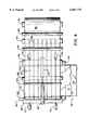
- FIG. 1 is a schematic isometric view of a package of a continuous strip according to the present invention, the package including a plurality of layers of the strip.
- FIG. 2 is a top plan view of the package of FIG. 1.
- FIG. 3 is an end elevational view of an apparatus and method for forming the package of FIG. 1.
- FIG. 4 is a top plan view of the apparatus of FIG. 5.
- FIG. 5 is a schematic side elevational view of a manufacturing line for cutting the strip into sheets.
- FIG. 6 is a top plan view of the line of FIG. 5.
- the package comprises a generally rectangular body 10 formed from a strip 11 of a material to be packaged.
- this material will be of a fibrous nature formed by woven or non-oven material although this is not essential to the package structure.
- Many materials of various thicknesses can be packaged using the festooning technique provided they can accept, without breaking, the creasing necessary at the end of each portion.
- Each package body includes at least one layer of the strip, also referred to herein as a stack, which comprises a plurality of folded strip portions of the strip which are laid on top of one another.
- the portions are folded back and forth at respective end fold lines 25 and 26 so that the fold lines lie in a common vertical plane defining the first sides 15 and 16 of the package.
- Each portion of the strip lies directly on top of the previous portion so that side edges 27 and 28 of the portions of the strip define a first set of lines in the common plane at right angles to the strip portions which contain all the side edges 27 of the layer and similarly, the side edges 28 of the strips of the layers define a second set of lines in the common plane at right angles to the strip portions which contain all the side edges 28 of the layers.
- the package is formed by laying the portions each on top of the next from a bottom portion 29 up to a top portion 30 to form the layer or stack.
- the package is thus formed from a plurality of layers 12 each of which has a length equal to that of the other layers and therefore equal to that of the package and the layers are formed up to a common height which is therefore equal to the height of the package.
- Each layer has a top end 13, a bottom end 14, two first sides 15 and 16 which are opposed and two second sides 17 and 18 which are opposed.
- the dimensions of the package can be varied in according to the requirements so that the number of layers can be increased or decreased, the length and height of each layer can be varied to increase the number of folded strip portions and to increase the length of the folded strip portions.
- the package can be oriented at right angles to the arrangement shown by lying the sacks or layers of strips on one side.
- the stacks or layers can be formed in a different orientation from that shown.
- the strips of each layer are folded back and forth from the fold lines 25 to the fold lines 26 to form a folded strip portion having a length equal to the distance between the fold lines.
- the strip is intended for manufacturing diapers or similar products which are formed each from a repective sheet element cut from the length of the strip.
- Each sheet element in the example shown has an intended cut line 34 at which it is intended to be separated from the next sheet element.
- the cut lines 34 are in effect imaginary lines.
- the position of the cut lines can however be determined by the design of the sheet elements and the position along the length of the strip which forms the beginning and end of the sheet elements.
- the strip is constant so that the position of the cut line is determined solely by a predetermined required length.
- the sheet elements are in effect thus arranged end to end so that each is separated, as shown and described hereinafter, from the next simply by cutting along the intended cut line.
- each folded strip portion of each of the package bodies is defined by an exact whole number of sheet elements.
- the number of sheet elements is three but this can of course be varied from a minimum of one up to a maximum which depends solely upon to maximum allowable size of the transportable package structure.
- the folded strip portion will contain more than one sheet element since the sheet elements are often of the order of six inches to two feet in length and the required package structure will be generally significantly larger than this and certainly of the order of four feet in length.
- each folded strip portion contains an exact whole number of sheet elements ensures that the cut lines occur substantially directly at the fold lines. Thus there are no fold lines across the strip in a central part of the sheet elements after the sheet elements are cut along the cut lines. This is extremely important in that the absence of fold lines in the material of the sheet elements will avoid compromising the performance or absorbency of the sheet element in the main body or central area of the sheet element.
- the package may be wrapped by a flexible packaging material preferably of heat sealable non-permeable plastics which encompasses the whole of the package.
- the packaging material forms a sealed package which may allow air to be extracted from the package and this vacuum action can be used, when packaging material which can be compressed, with physical compression from the sides 16 and 17 of the package so as to compress the package to a reduced height in a vacuum packaging system.
- the amount of compressions if any, can be determined so as to minimize the volume of the package without interfering with the required loft of the product when withdrawn from the package. In this way the package structure avoids the necessity for rigid sides of a box or similar container so the package structure is stable due to the compression of the layers to reduce the height of the layers and due to the pressure of each layer against the sides of the next adjacent layers.
- Compression of the package is only possible in the direction D which is at right angles to the surfaces of the portions of the strip. This acts to compress the thickness of the portions so that the dimension of each layer in the direction D is reduced by that compression. Compression along the portions or at right angles to the layers is not possible since this will act to distort the strip.
- Mechanical compression therefore of the package in the direction D thus reduces the dimension of the package in that direction allowing the air to be withdrawn from the flexible packaging material causing the packaging material to be pulled down onto the package to maintain it in its compressed condition and to apply pressures tending to hold the layers in intimate contact. Further detail of the packaging and compression arrangement are shown in the above applications.
- the strip of each layer is connected to the next by a traverse or spliced portion of the strip which extends from one layer to the next so as to form a continuous strip through the full length of the package.
- the technique for connecting the strip of each layer to the next layer is shown and described in more detail in the above applications.
- a web 50 is supplied on a master roll 51 and is unwound from the master roll by a feeding and guide system 62 including two nip roller pairs 53 and 54.
- a slitting system 55 is mounted transversely to the web for dividing the web into a plurality of parallel side by side strips. This can be provided a by a slitter bar which carries a plurality of slitter knives at transversely spaced positions so as to slit the web into a plurality of strips 57 which are carried forwardly by the guide system 52 so that they are maintained in the common plane of the web and are maintained edge to edge.
- the strips 57 are fed over a guide roller 58 into a folding system generally indicated at 59 located underneath the feed roller 58.
- the folding system 59 comprises a support table 60 having a width sufficient to receive the full width of the web 50 when stretched out as shown in FIG. 5, that is the strips in side by side arrangement.
- the support table 60 has a length sufficient to receive the portions of the folded strips in the structure as previously described.
- the table 60 is mounted upon a jacking system 61 which is shown only shematically and acts to raise and lower the table so that the table is gradually lowered as the strips are folded onto the table.
- the folding system further includes a pair of folding bars 62 and 63 which act to fold the strips back and forth across the table 60.
- the folding bar 62 is mounted on an actuating cylinder 64 and similarly the folding bar 63 is mounted on an actuating cylinder 65.
- the folding bar 63 is shown in the retracted position and the folding bar 62 is shown in the extended position.
- the folding bars move alternately between these positions so that the folding bar 62 is firstly retracted and then the folding bar 63 is extended so as to move the strips across the table to form the overlying portions of the strip previously described.
- the folding bars 62 and 63 extend across the full width of the web so as to engage all of the strips simultaneously and to move those strips simultaneously into the folded positions.
- the strips thus remain in the above described position as they are being folded.
- the folding bars 62 and 63 may be in the form of rollers to allow the material to pass over the bar without friction while the material is being pushed by the bar to the required position on the table.
- the mounting system for supporting the cylinders is not shown for convenience of illustration and this will of course be well apparent to one skilled in the art
- the folding system further includes a pair of creasing jaws 66 and 67 each arranged at the end of the stroke of a respective one of the folding bars.
- the creasing jaws also extend across the full width of the web and comprise a pair of jaw elements 68 and 69 which can be moved from an open position as indicated on the left and a closed creasing position as indicated on the right.
- the jaws are moved between these positions by an actuating cylinder 70 timed in relation to the operation of the cylinder 64 and 65.
- the creasing jaws In addition to the opening and closing movement, the creasing jaws also move inwardly and outwardly in a horizontal direction relative to the table so as to release each fold or crease line after it is formed to allow that layer and the fold at the end of the layer to be dropped onto the previous layers and to move downwardly with the table 60.
- the creasing jaw 66 at the completion of the crease moves outwardly away from the crease or fold line and at the same time opens slightly to release the fold between the two portions to drop downwardly onto the underlying portions.
- the jaws then open and move back inwardly ready to receive the portion of the strips wrapped around the folding bar and to grasp those as they are released from the folding bar as shown at the creasing jaw 67 in FIG. 4.
- This compound motion can be effected by suitable mechanical linkage operated by the actuating cylinder 70, this arrangement again being well apparent to one skilled in this art.
- the strips are therefore simultaneously laid down in portions folded back and forth on top of one another to simultaneously form a plurality of the layers of the package structure. Each layer is thus formed by a single respective one of the strips.
- the strip is continuous throughout the layer.
- one or more master rolls may be spliced into the supply with the splice being formed across the width of the web so that each slit strip also acts to slit through the splice.
- a marker 56B is located adjacent the packaging system 59 for applying a machine readable marking 56C on the strip in registration with the intended cutting lines for dividing each sheet element from the next the markings shown as a chain dot line in FIGS. 2 and 6 can comprise an ink jet marking, possibly in the form of a dot or square, visible both to the eye and to the machine or in some cases just to the machine.
- the marking may or may not be located directly at the cut line depending upon the location of the machine reader relative to the cutting blade and in the example shown, the marking is located in advance of the intended line. The marking may extend only across a short part of the width of the strip. It will be appreciated that as the markings are registered with respective ones of the cut lines, each marking is offset from its associated cut line by the same distance.
- each intended cut line can be marked and therefore there will be a plurality of markings on each strip portion.
- FIGS. 5 and 6 there is shown schematically the unfolding and cutting line for using the strip and separating the strip into the separate sheet elements.
- the package is indicated at 10 and the strip is withdrawn from the package over a guide member 80 for directing into an operating line 81.
- a cutting device 82 is operated by a control unit 83 which receives registration information from the markings 56C as read by a reader 84.
- the markings are located at a position to operate the control device to effect cutting at the intended cut line.
- the cut lines are located at the fold lines. Depending upon tolerances, the cut may not be effected directly at the fold line but may deviate slightly therefrom.
- the cut line can deviate from the fold line by a small amount provided the fold line does not end up in a central absorbent area 85 of the final product, indicated by dash lines 86, 87. That is the fold lines are arranged sufficiently close to an end of the sheet elements to avoid compromising the performance of the sheet elements.
Abstract
Description
Claims (15)
Priority Applications (36)
| Application Number | Priority Date | Filing Date | Title |
|---|---|---|---|
| US08/975,037 US6067775A (en) | 1997-11-18 | 1997-11-18 | Packaging a strip of material by folding |
| MYPI9802640 MY114949A (en) | 1997-06-19 | 1998-06-12 | Packaging a strip of material |
| DK98929172T DK0910542T3 (en) | 1997-06-19 | 1998-06-17 | Packaging of web-shaped material |
| DE29823583U DE29823583U1 (en) | 1997-06-19 | 1998-06-17 | Material strip pack |
| EP98929172A EP0910542B1 (en) | 1997-06-19 | 1998-06-17 | Packaging a strip of material |
| JP50345799A JP2002507174A (en) | 1997-06-19 | 1998-06-17 | Long package |
| NZ500798A NZ500798A (en) | 1997-06-19 | 1998-06-17 | Packaging a strip of material having top and bottom portions with end connecting portions |
| IL13356998A IL133569A (en) | 1997-06-19 | 1998-06-17 | Packaging a strip of material |
| CA002274272A CA2274272C (en) | 1997-06-19 | 1998-06-17 | Packaging a strip of material |
| EA200000034A EA001473B1 (en) | 1997-06-19 | 1998-06-17 | Packeging a strip of material |
| ES98929172T ES2148007T3 (en) | 1997-06-19 | 1998-06-17 | PACKAGING OF A STRIP OF MATERIAL. |
| SK1815-99A SK283739B6 (en) | 1997-06-19 | 1998-06-17 | Packaging a strip of material |
| CZ19994590A CZ9904590A3 (en) | 1997-06-19 | 1998-06-17 | Package of a strip of material and method for forming such package of a strip of material |
| HU0004788A HUP0004788A3 (en) | 1997-06-19 | 1998-06-17 | Packaging a strip of material and a method to form it |
| AU79028/98A AU734791B2 (en) | 1997-06-19 | 1998-06-17 | Packaging a strip of material |
| APAP/P/1999/001689A AP9901689A0 (en) | 1997-06-19 | 1998-06-17 | Packaging a strip of material. |
| KR10-1999-7012016A KR100399777B1 (en) | 1997-06-19 | 1998-06-17 | A package of a strip of material and a method for supplying a strip of material |
| PT98929172T PT910542E (en) | 1997-06-19 | 1998-06-17 | PACKAGING OF A STRIP OF MATERIAL |
| DE19881126T DE19881126T1 (en) | 1997-06-19 | 1998-06-17 | Form a pack of a strip of material |
| BR9810162-5A BR9810162A (en) | 1997-06-19 | 1998-06-17 | Packing a strip of material |
| DE69800128T DE69800128T2 (en) | 1997-06-19 | 1998-06-17 | PACKING A MATERIAL RAIL |
| DE29823901U DE29823901U1 (en) | 1997-06-19 | 1998-06-17 | Material strip pack |
| TR1999/03129T TR199903129T2 (en) | 1997-06-19 | 1998-06-17 | Packing a strip of material. |
| CNB988063050A CN1201989C (en) | 1997-06-19 | 1998-06-17 | Packaging strip of material |
| AT98929172T ATE192117T1 (en) | 1997-06-19 | 1998-06-17 | PACKAGING A WEB OF MATERIAL |
| YU67199A YU67199A (en) | 1997-06-19 | 1998-06-17 | Packing a strip of material |
| PCT/CA1998/000592 WO1998058864A1 (en) | 1997-06-19 | 1998-06-17 | Packaging a strip of material |
| PL98337160A PL187211B1 (en) | 1997-06-19 | 1998-06-17 | Method of forming a pack of fibrous material ribbon and pack formed thereby |
| US09/370,240 US6336307B1 (en) | 1997-10-09 | 1999-08-09 | Method of packaging a strip of material for use in cutting into sheet elements arranged end to end |
| HK99104597A HK1020185A1 (en) | 1997-06-19 | 1999-10-19 | Packaging a strip of material |
| OA9900259A OA11263A (en) | 1997-06-19 | 1999-11-26 | Packaging a strip of material |
| NO996293A NO996293L (en) | 1997-06-19 | 1999-12-17 | Wrapping a ribbon material |
| GR20000401694T GR3034008T3 (en) | 1997-06-19 | 2000-07-24 | Packaging a strip of material |
| US10/029,450 US6643993B2 (en) | 1997-10-09 | 2001-12-20 | Method of packaging a strip of material for use in cutting into sheet elements arranged end to end |
| JP2003080823A JP2003312758A (en) | 1997-06-19 | 2003-03-24 | Package of continuous article |
| JP2004141636A JP2004238207A (en) | 1997-06-19 | 2004-05-11 | Long-size material package |
Applications Claiming Priority (1)
| Application Number | Priority Date | Filing Date | Title |
|---|---|---|---|
| US08/975,037 US6067775A (en) | 1997-11-18 | 1997-11-18 | Packaging a strip of material by folding |
Related Parent Applications (1)
| Application Number | Title | Priority Date | Filing Date |
|---|---|---|---|
| US94825897A Continuation-In-Part | 1997-06-19 | 1997-10-09 |
Related Child Applications (2)
| Application Number | Title | Priority Date | Filing Date |
|---|---|---|---|
| US94825897A Continuation-In-Part | 1997-06-19 | 1997-10-09 | |
| US09/370,240 Continuation-In-Part US6336307B1 (en) | 1997-10-09 | 1999-08-09 | Method of packaging a strip of material for use in cutting into sheet elements arranged end to end |
Publications (1)
| Publication Number | Publication Date |
|---|---|
| US6067775A true US6067775A (en) | 2000-05-30 |
Family
ID=25522644
Family Applications (1)
| Application Number | Title | Priority Date | Filing Date |
|---|---|---|---|
| US08/975,037 Expired - Lifetime US6067775A (en) | 1997-06-19 | 1997-11-18 | Packaging a strip of material by folding |
Country Status (1)
| Country | Link |
|---|---|
| US (1) | US6067775A (en) |
Cited By (6)
| Publication number | Priority date | Publication date | Assignee | Title |
|---|---|---|---|---|
| US6253996B1 (en) * | 1997-06-20 | 2001-07-03 | Oki Electric Industry Co., Ltd. | Medium handling apparatus |
| US20020157982A1 (en) * | 2001-03-20 | 2002-10-31 | Steegs Wilhelmus L.J. Marie | Method of packing a batch of image-receiving material and a batch of image-receiving material enclosed by a container |
| US20040159658A1 (en) * | 2003-02-14 | 2004-08-19 | Mclaughlin Michael Ray | Packages, packaging systems, methods for packaging and apparatus for packaging |
| US20120329628A1 (en) * | 2009-12-28 | 2012-12-27 | Rofobox Gmbh | Folding apparatus for folding of non-rigid material parts |
| US20130184138A1 (en) * | 2012-01-18 | 2013-07-18 | Neil C. Waldrop | Method and apparatus for forming fan-folded web of labels with improved registration |
| US11433791B2 (en) * | 2020-04-09 | 2022-09-06 | Lear Corporation | Trim assembly for a vehicle seat and method of forming |
Citations (32)
| Publication number | Priority date | Publication date | Assignee | Title |
|---|---|---|---|---|
| US32761A (en) * | 1861-07-09 | Machiite eoe | ||
| US1463918A (en) * | 1920-08-31 | 1923-08-07 | Joseph N Borroughs | Machine for folding towels |
| US1985676A (en) * | 1933-01-28 | 1934-12-25 | Leslie T Hand | Method of and machine for slitting and stacking folded plies of paper web |
| US3245680A (en) * | 1962-03-28 | 1966-04-12 | Pratt Mfg Corp | Variable packaging machine |
| US3351992A (en) * | 1964-02-04 | 1967-11-14 | Eastman Kodak Co | Method for packaging tow |
| US3673757A (en) * | 1971-01-04 | 1972-07-04 | Arnold L Willis | Method of making pillows |
| US3684275A (en) * | 1970-03-09 | 1972-08-15 | Clevite Corp | Device for zig-zag folding an oscillographic record chart |
| US3729367A (en) * | 1971-06-01 | 1973-04-24 | Oliver Tire & Rubber Co | Rubber product for tire recapping apparatus and method for making |
| US3739544A (en) * | 1971-02-12 | 1973-06-19 | Feldmuehle Ag | Method and apparatus for the shrink-wrapping of packages |
| US4097039A (en) * | 1976-07-23 | 1978-06-27 | Applied Power Inc. | Strip laying apparatus |
| US4201029A (en) * | 1978-08-14 | 1980-05-06 | Automated Packaging Systems, Inc. | Method and apparatus for packaging |
| US4240854A (en) * | 1978-10-31 | 1980-12-23 | Avery International Corporation | Fan-folded labeling technique |
| JPS5747638A (en) * | 1980-09-05 | 1982-03-18 | Tokyo Gas Co Ltd | Method for inserting soft belt through flexible cylindrical object and device thereof |
| US4418514A (en) * | 1980-10-06 | 1983-12-06 | Spann Donald C | Orthopedic support package and method |
| US4427404A (en) * | 1980-12-25 | 1984-01-24 | Yoshida Kogyo K. K. | Apparatus for stacking a tape of indefinite length in folded condition |
| AU2298383A (en) * | 1980-12-25 | 1984-05-03 | Yoshida Kogyo K.K. | Stacking tape-shaking off means |
| US4499707A (en) * | 1979-03-09 | 1985-02-19 | Rhone-Poulenc-Textile | Method and apparatus for baling a tow of textile filaments |
| US4547184A (en) * | 1982-08-30 | 1985-10-15 | B. Bunch Company, Inc. | Delivery mechanism for paper sheet processing apparatus |
| US4597748A (en) * | 1984-10-04 | 1986-07-01 | Wolf Robert A | Method and apparatus for forming gauze pads |
| US4603817A (en) * | 1982-02-04 | 1986-08-05 | Oconnor Lawrence | Package of tape |
| US4716706A (en) * | 1983-11-15 | 1988-01-05 | Minigrip, Inc. | Bag folding and packaging apparatus |
| US4846454A (en) * | 1988-02-22 | 1989-07-11 | Th Stralfors Ab | Method and apparatus for folding, stacking and separating continuous forms in a moving web |
| US4896475A (en) * | 1989-02-21 | 1990-01-30 | Polysar Financial Services S.A. | Rocker frame |
| SU1555205A1 (en) * | 1987-08-21 | 1990-04-07 | Предприятие П/Я В-2441 | Method of placing fire hose |
| US4941374A (en) * | 1987-06-25 | 1990-07-17 | Focke & Co. (Gmbh & Co.) | Process and apparatus for the loading of pallets in layers |
| JPH02182666A (en) * | 1989-01-06 | 1990-07-17 | Kobayashi Seisakusho:Kk | Folding accumulating device of strip material and accumulating method |
| US5064179A (en) * | 1987-12-10 | 1991-11-12 | Syntone | Method of forming zigzag-shaped piles from a continuous band of a flexible material and machine for carrying out this method |
| US5087140A (en) * | 1989-12-14 | 1992-02-11 | Keeton J Herbert | Festooning machine for cloth strips |
| US5104366A (en) * | 1991-05-15 | 1992-04-14 | B. Bunch Company, Inc. | Apparatus for folding a series of separated business forms with the top sheet of each form in a common orientation |
| US5177934A (en) * | 1990-12-28 | 1993-01-12 | Daiho Giken Co., Ltd. | Packaged toilet paper and method of manufacturing thereof |
| US5290226A (en) * | 1992-12-23 | 1994-03-01 | G. Fordyce Company, Inc. | Method of and apparatus for cutting a web and folding the resulting ribbons |
| US5529564A (en) * | 1992-12-04 | 1996-06-25 | Jos. Hunkeler, Ltd. | Apparatus for depositing, guiding and pressing material web parts to be stacked |
-
1997
- 1997-11-18 US US08/975,037 patent/US6067775A/en not_active Expired - Lifetime
Patent Citations (32)
| Publication number | Priority date | Publication date | Assignee | Title |
|---|---|---|---|---|
| US32761A (en) * | 1861-07-09 | Machiite eoe | ||
| US1463918A (en) * | 1920-08-31 | 1923-08-07 | Joseph N Borroughs | Machine for folding towels |
| US1985676A (en) * | 1933-01-28 | 1934-12-25 | Leslie T Hand | Method of and machine for slitting and stacking folded plies of paper web |
| US3245680A (en) * | 1962-03-28 | 1966-04-12 | Pratt Mfg Corp | Variable packaging machine |
| US3351992A (en) * | 1964-02-04 | 1967-11-14 | Eastman Kodak Co | Method for packaging tow |
| US3684275A (en) * | 1970-03-09 | 1972-08-15 | Clevite Corp | Device for zig-zag folding an oscillographic record chart |
| US3673757A (en) * | 1971-01-04 | 1972-07-04 | Arnold L Willis | Method of making pillows |
| US3739544A (en) * | 1971-02-12 | 1973-06-19 | Feldmuehle Ag | Method and apparatus for the shrink-wrapping of packages |
| US3729367A (en) * | 1971-06-01 | 1973-04-24 | Oliver Tire & Rubber Co | Rubber product for tire recapping apparatus and method for making |
| US4097039A (en) * | 1976-07-23 | 1978-06-27 | Applied Power Inc. | Strip laying apparatus |
| US4201029A (en) * | 1978-08-14 | 1980-05-06 | Automated Packaging Systems, Inc. | Method and apparatus for packaging |
| US4240854A (en) * | 1978-10-31 | 1980-12-23 | Avery International Corporation | Fan-folded labeling technique |
| US4499707A (en) * | 1979-03-09 | 1985-02-19 | Rhone-Poulenc-Textile | Method and apparatus for baling a tow of textile filaments |
| JPS5747638A (en) * | 1980-09-05 | 1982-03-18 | Tokyo Gas Co Ltd | Method for inserting soft belt through flexible cylindrical object and device thereof |
| US4418514A (en) * | 1980-10-06 | 1983-12-06 | Spann Donald C | Orthopedic support package and method |
| US4427404A (en) * | 1980-12-25 | 1984-01-24 | Yoshida Kogyo K. K. | Apparatus for stacking a tape of indefinite length in folded condition |
| AU2298383A (en) * | 1980-12-25 | 1984-05-03 | Yoshida Kogyo K.K. | Stacking tape-shaking off means |
| US4603817A (en) * | 1982-02-04 | 1986-08-05 | Oconnor Lawrence | Package of tape |
| US4547184A (en) * | 1982-08-30 | 1985-10-15 | B. Bunch Company, Inc. | Delivery mechanism for paper sheet processing apparatus |
| US4716706A (en) * | 1983-11-15 | 1988-01-05 | Minigrip, Inc. | Bag folding and packaging apparatus |
| US4597748A (en) * | 1984-10-04 | 1986-07-01 | Wolf Robert A | Method and apparatus for forming gauze pads |
| US4941374A (en) * | 1987-06-25 | 1990-07-17 | Focke & Co. (Gmbh & Co.) | Process and apparatus for the loading of pallets in layers |
| SU1555205A1 (en) * | 1987-08-21 | 1990-04-07 | Предприятие П/Я В-2441 | Method of placing fire hose |
| US5064179A (en) * | 1987-12-10 | 1991-11-12 | Syntone | Method of forming zigzag-shaped piles from a continuous band of a flexible material and machine for carrying out this method |
| US4846454A (en) * | 1988-02-22 | 1989-07-11 | Th Stralfors Ab | Method and apparatus for folding, stacking and separating continuous forms in a moving web |
| JPH02182666A (en) * | 1989-01-06 | 1990-07-17 | Kobayashi Seisakusho:Kk | Folding accumulating device of strip material and accumulating method |
| US4896475A (en) * | 1989-02-21 | 1990-01-30 | Polysar Financial Services S.A. | Rocker frame |
| US5087140A (en) * | 1989-12-14 | 1992-02-11 | Keeton J Herbert | Festooning machine for cloth strips |
| US5177934A (en) * | 1990-12-28 | 1993-01-12 | Daiho Giken Co., Ltd. | Packaged toilet paper and method of manufacturing thereof |
| US5104366A (en) * | 1991-05-15 | 1992-04-14 | B. Bunch Company, Inc. | Apparatus for folding a series of separated business forms with the top sheet of each form in a common orientation |
| US5529564A (en) * | 1992-12-04 | 1996-06-25 | Jos. Hunkeler, Ltd. | Apparatus for depositing, guiding and pressing material web parts to be stacked |
| US5290226A (en) * | 1992-12-23 | 1994-03-01 | G. Fordyce Company, Inc. | Method of and apparatus for cutting a web and folding the resulting ribbons |
Cited By (16)
| Publication number | Priority date | Publication date | Assignee | Title |
|---|---|---|---|---|
| US6253996B1 (en) * | 1997-06-20 | 2001-07-03 | Oki Electric Industry Co., Ltd. | Medium handling apparatus |
| US6874622B2 (en) * | 2001-03-20 | 2005-04-05 | Océ-Technologies B.V. | Method of packing a batch of image-receiving material and a batch of image-receiving material enclosed by a container |
| US20020157982A1 (en) * | 2001-03-20 | 2002-10-31 | Steegs Wilhelmus L.J. Marie | Method of packing a batch of image-receiving material and a batch of image-receiving material enclosed by a container |
| US7958696B2 (en) | 2003-02-14 | 2011-06-14 | Eastman Chemical Company | Packages, packaging systems, methods for packaging and apparatus for packaging |
| US20060272960A1 (en) * | 2003-02-14 | 2006-12-07 | Mclaughlin Michael R | Packages, packaging systems, methods for packaging and apparatus for packaging |
| US20070022718A1 (en) * | 2003-02-14 | 2007-02-01 | Mclaughlin Michael R | Packages, packaging systems, methods for packaging and apparatus for packaging |
| US7739857B2 (en) | 2003-02-14 | 2010-06-22 | Eastman Chemical Company | Packages, packaging systems, methods for packaging and apparatus for packaging |
| US20100236194A1 (en) * | 2003-02-14 | 2010-09-23 | Eastman Chemical Company | Packages, packaging systems, methods for packaging and apparatus for packaging |
| US20040159658A1 (en) * | 2003-02-14 | 2004-08-19 | Mclaughlin Michael Ray | Packages, packaging systems, methods for packaging and apparatus for packaging |
| US20110203228A1 (en) * | 2003-02-14 | 2011-08-25 | Eastman Chemical Company | Packages, packaging systems, methods for packaging and apparatus for packaging |
| US8671652B2 (en) | 2003-02-14 | 2014-03-18 | Eastman Chemical Company | Packages, packaging systems, methods for packaging and apparatus for packaging |
| US9598184B2 (en) | 2003-02-14 | 2017-03-21 | Eastman Chemical Company | Method for packaging fiber material |
| US20120329628A1 (en) * | 2009-12-28 | 2012-12-27 | Rofobox Gmbh | Folding apparatus for folding of non-rigid material parts |
| US20130184138A1 (en) * | 2012-01-18 | 2013-07-18 | Neil C. Waldrop | Method and apparatus for forming fan-folded web of labels with improved registration |
| US8939877B2 (en) * | 2012-01-18 | 2015-01-27 | Century Printing & Packaging, Inc. | Method and apparatus for forming fan-folded web of labels with improved registration |
| US11433791B2 (en) * | 2020-04-09 | 2022-09-06 | Lear Corporation | Trim assembly for a vehicle seat and method of forming |
Similar Documents
| Publication | Publication Date | Title |
|---|---|---|
| US6336307B1 (en) | Method of packaging a strip of material for use in cutting into sheet elements arranged end to end | |
| US5966905A (en) | Packaging a strip of material in layers with intervening splices | |
| US4475730A (en) | Apparatus for folding and stacking paper products | |
| US6612097B2 (en) | Packaging a strip of material | |
| CA2632083C (en) | Packaging a strip of material in side by side stacks spliced end to end | |
| US5927051A (en) | Packaging a continuous strip of material | |
| EP0910542B1 (en) | Packaging a strip of material | |
| US6729471B2 (en) | Packaging a strip of material with compression to reduce volume | |
| US20080113855A1 (en) | Multi-Panel Dispenser Napkin | |
| US6321511B1 (en) | Packaging a strip of material with compression to reduce volume | |
| US6067775A (en) | Packaging a strip of material by folding | |
| US6293075B1 (en) | Packaging a strip of material | |
| US5987851A (en) | Packaging a strip of material | |
| EP0512355B1 (en) | Book package blank and method and machine for its fabrication | |
| US6176068B1 (en) | Packaging a strip of material in layers with intervening splices | |
| CA2436221C (en) | Packaging a strip of material of varying width | |
| CA2436441C (en) | Packaging a strip of material for use in cutting into sheet elements arranged end to end | |
| JP2001286410A (en) | Method for producing wet tissue package body and variable folding plate device therefor | |
| US6009689A (en) | Packaging a strip of material in layers | |
| US3136277A (en) | Method of making paper bags | |
| JP3073517U (en) | Variable folding plate device for manufacturing wet tissue laminates | |
| EP1695933A2 (en) | Method of splicing a strip material and method of forming a package of said strip material | |
| IT9021623A1 (en) | EQUIPMENT AND PROCEDURE FOR THE PRODUCTION OF CONTAINERS. | |
| AU2382599A (en) | Folded towel stack |
Legal Events
| Date | Code | Title | Description |
|---|---|---|---|
| AS | Assignment |
Owner name: KT HOLDINGS INC., CANADA Free format text: ASSIGNMENT OF ASSIGNORS INTEREST;ASSIGNOR:O'CONNOR, LAWRENCE J.;REEL/FRAME:009247/0624 Effective date: 19980210 Owner name: STAC-PAC TECHNOLOGIES INC., BARBADOS Free format text: ASSIGNMENT OF ASSIGNORS INTEREST;ASSIGNOR:KT HOLDINGS LTD.;REEL/FRAME:009247/0648 Effective date: 19980210 |
|
| AS | Assignment |
Owner name: BKI HOLDING CORPORATION, DELAWARE Free format text: ASSIGNMENT OF ASSIGNORS INTEREST;ASSIGNOR:STAC PAC TECHNOLOGIES INC.;REEL/FRAME:010742/0017 Effective date: 20000301 |
|
| STCF | Information on status: patent grant |
Free format text: PATENTED CASE |
|
| AS | Assignment |
Owner name: FLEET NATIONAL BANK, MASSACHUSETTS Free format text: SECURITY AGREEMENT;ASSIGNOR:BKI HOLDING COMPANY;REEL/FRAME:012506/0128 Effective date: 20010416 |
|
| FEPP | Fee payment procedure |
Free format text: PAT HOLDER NO LONGER CLAIMS SMALL ENTITY STATUS, ENTITY STATUS SET TO UNDISCOUNTED (ORIGINAL EVENT CODE: STOL); ENTITY STATUS OF PATENT OWNER: LARGE ENTITY |
|
| REFU | Refund |
Free format text: REFUND - SURCHARGE, PETITION TO ACCEPT PYMT AFTER EXP, UNINTENTIONAL (ORIGINAL EVENT CODE: R2551); ENTITY STATUS OF PATENT OWNER: LARGE ENTITY |
|
| FPAY | Fee payment |
Year of fee payment: 4 |
|
| AS | Assignment |
Owner name: BUCKEYE TECHNOLOGIES INC., TENNESSEE Free format text: MERGER;ASSIGNOR:BKI HOLDING CORPORATION;REEL/FRAME:019550/0923 Effective date: 20070630 |
|
| AS | Assignment |
Owner name: STAC-PAC TECHNOLOGIES, INC., BARBADOS Free format text: CORRECTIVE ASSIGNMENT TO CORRECT THE THE NAME OF THE CONVEYING PARTY PREVIOUSLY RECORDED ON REEL 009247 FRAME 0648;ASSIGNOR:KT HOLDINGS, INC.;REEL/FRAME:019597/0514 Effective date: 19980210 |
|
| FPAY | Fee payment |
Year of fee payment: 8 |
|
| FPAY | Fee payment |
Year of fee payment: 12 |
|
| AS | Assignment |
Owner name: BUCKEYE TECHNOLOGIES INC., TENNESSEE Free format text: RELEASE BY SECURED PARTY;ASSIGNOR:BANK OF AMERICA, N.A.;REEL/FRAME:064321/0653 Effective date: 20201031 |