US6033413A - Stent delivery system - Google Patents
Stent delivery system Download PDFInfo
- Publication number
- US6033413A US6033413A US09/063,118 US6311898A US6033413A US 6033413 A US6033413 A US 6033413A US 6311898 A US6311898 A US 6311898A US 6033413 A US6033413 A US 6033413A
- Authority
- US
- United States
- Prior art keywords
- catheter
- stent
- distal end
- delivery system
- lumen
- Prior art date
- Legal status (The legal status is an assumption and is not a legal conclusion. Google has not performed a legal analysis and makes no representation as to the accuracy of the status listed.)
- Expired - Fee Related
Links
Images


Classifications
-
- A—HUMAN NECESSITIES
- A61—MEDICAL OR VETERINARY SCIENCE; HYGIENE
- A61F—FILTERS IMPLANTABLE INTO BLOOD VESSELS; PROSTHESES; DEVICES PROVIDING PATENCY TO, OR PREVENTING COLLAPSING OF, TUBULAR STRUCTURES OF THE BODY, e.g. STENTS; ORTHOPAEDIC, NURSING OR CONTRACEPTIVE DEVICES; FOMENTATION; TREATMENT OR PROTECTION OF EYES OR EARS; BANDAGES, DRESSINGS OR ABSORBENT PADS; FIRST-AID KITS
- A61F2/00—Filters implantable into blood vessels; Prostheses, i.e. artificial substitutes or replacements for parts of the body; Appliances for connecting them with the body; Devices providing patency to, or preventing collapsing of, tubular structures of the body, e.g. stents
- A61F2/0004—Closure means for urethra or rectum, i.e. anti-incontinence devices or support slings against pelvic prolapse
- A61F2/0009—Closure means for urethra or rectum, i.e. anti-incontinence devices or support slings against pelvic prolapse placed in or outside the body opening close to the surface of the body
Definitions
- This invention relates to stent delivery systems to facilitate the treatment for benign prostate hypertrophy or prostate cancer.
- Prostate enlargement also known as benign prostate hyperplasia or benign prostate hypertrophy
- the condition involves swelling of the prostate.
- the prostate surrounds the urethra, or urinary tract, and swelling of the prostate prevents passage of urine from the bladder.
- Benign prostate hyperplasia is uncomfortable because it makes urination difficult or impossible.
- the condition is also dangerous because it can lead to infection of the bladder and kidneys, and severe cases may lead to death.
- Prostate cancer is also a common affliction among older men, and may lead to many of the same symptoms as benign prostate enlargement. Prostate cancer is more dangerous in that it may spread to other organs and is often fatal. Early treatment can reduce the risks of death due to prostate cancer.
- a stent serves the dual purpose of acting as a heat source for the thermotherapy procedures, as well as acting to hold the urethra open after therapy to prevent blockage due to swelling and prostate tissue sloughing.
- a stent may be implanted as an interim solution to hold open the urethra while the patient awaits more aggressive surgery or treatment.
- a stent may be implanted after hypothermia or cryosurgery to keep the urethra open while enlargement subsides.
- a stent may be implanted as a primary treatment.
- the stent When the stent is implanted for any of these reasons, it is usually better to leave the bladder neck sphincter and the external sphincter un-blocked by the stent. These sphincters control the flow of urine through the urethra, and if the stent is placed within these sphincters they will not be able to close. This would leave the patient incontinent.
- the devices below provide several benefits including visualization of the bladder and prostatic urethra during placement, anchoring of the insertion catheter in place during insertion, and distal-first deployment of the stent.
- the stent delivery systems described below permit placement of stents in the urethra.
- the devices are intended to deploy a shape memory stent into the prostatic urethra under direct vision.
- the surgeons who use the stent delivery systems can easily place the stent within the prostatic urethra and make sure that the stent does not block the bladder neck sphincter. This is accomplished by anchoring the stent insertion catheter within the bladder, locating the stent under direct vision, and expanding the stent from the distal end first, then expanding the proximal end.
- Direct vision is accomplished by use of an endoscope in the central lumen of the insertion catheter which has a transparent catheter wall.
- the insertion catheter has a valved tip which permits the use of the central lumen with an insertion guidewire to assist in pushing the device into the prostatic urethra, but also provides for closure of the central lumen so that water may be injected through the catheter and will preferentially flow out of the catheter through vent ports which direct flow to the stent.
- the vent ports are blocked or throttled by the endoscope until the endoscope is pulled proximally in the central lumen to open vent ports to a fluid supplied into the central lumen through the working channel of the endoscope.
- the device may be provided as a disposable item which is generally composed of a catheter with a mesh basket, a toroidal shaped balloon or a malecot attached at its distal end which serves to anchor the device in place, a stent mounted near the distal end of the catheter, a proximal manifold of ports supplying necessary access for endoscopes and fluid injection, and a peel-away protective sheath, all designed for use with standard endoscopes.
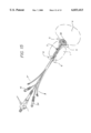
- FIG. 1 is a cross-sectional view of the lower abdominal portion of the human body with a stent delivery system in place.
- FIG. 2 shows a surface view of an embodiment of the stent delivery system.
- FIG. 3 shows a surface view of the inner and outer catheter shafts of the stent delivery system.
- FIG. 4 shows an exploded view of the inner and outer catheter shafts of the stent delivery system.
- FIG. 5 shows an exploded view of the outer catheter shafts, stent, peel away sheath and stent restrictor of the stent delivery system.
- FIG. 6 illustrates the use of the stent delivery system with the mesh basket anchor in the expanded shape.
- FIG. 7 illustrates the use of the stent delivery system with the mesh basket anchor in the expanded shape within the bladder.
- FIG. 8 is a radial cross section of the catheter shaft.
- FIG. 9 illustrates the use of the stent delivery system with an expandable mesh anchor.
- FIG. 10 illustrates an embodiment of the stent delivery system with a balloon anchor.
- FIG. 11 is a cross section of the stent delivery system with a balloon anchor designed for use with an endoscope having a working channel.
- FIG. 12 is radial cross section of the stent delivery system of FIG. 11.
- FIG. 13 is a cross section of the stent delivery system with a balloon anchor designed for use with an endoscope without a working channel.
- FIG. 14 is radial cross section of the stent delivery system of FIG. 13.
- FIGS. 15 is a surface view of the stent delivery system of FIG. 10.
- FIG. 16 shows a surface view of the stent delivery system employing a balloon anchor and a separate distal valve.
- FIG. 17 is a longitudinal cross section of the stent delivery system of FIG. 16
- FIG. 18 illustrates the method of removing the stent after use.
- FIG. 1 shows a schematic representation of the stent delivery system designed for use in the treatment of benign prostate hyperplasia or prostate cancer in place within the human body.
- the details of the local anatomy shown in FIG. 1 include the prostate gland 1, the urethra 2, the prostatic urethra 3, and the bladder 4.
- the urethra 2 is the channel which conducts urine from the bladder 4 to the penis for discharge from the body.
- the prostatic urethra 3 is a continuation of the urethra 2, and it joins the prostate gland 1 to the urethra 2.
- the bladder neck sphincter 5 controls flow of urine from the bladder 4 through the bladder neck 5a.
- the external sphincter 6 controls flow of urine or ejaculate from the bladder 4 or prostate 1.
- the inside diameter of urethra 2 is typically about 2 cm, and the prostatic urethra 3 varies in length from about 15 to 75 mm.
- the stent 7 is delivered to the prostatic urethra 3 within the bladder 4 by the stent delivery system 8 illustrated in the various following Figures.
- a first embodiment of the stent delivery system is shown in more detail in FIG. 2.
- the stent delivery system 8 generally includes a catheter inner shaft 9, a catheter outer shaft 10, a peel away sheath 11, and a stent retainer 12 mounted on the catheter inner shaft just proximal of the stent 7 (hidden in this view under stent restrictor 13 and peel away sheath 11).
- the peel away sheath extends from the proximal end of the device to the distal end of the device, covering all the uneven surfaces of the stent, the anchor device, and the retainers.
- a stent restrictor 13 surrounds the stent and the peel away sheath in the area of the stent.
- An expandable mesh basket type anchor 14 is secured to the distal tip of the inner shaft 9 with basket mounting ring 15, and the proximal end of the basket is slidably mounted on the inner shaft 9 by sliding mounting ring 16.
- the mesh basket is made of plastic mesh with mesh fibers oriented diagonally around the circumference of the mesh tube, at an angle to the longitudinal and radial dimensions of the tube.
- the mesh anchor When uncompressed, the mesh anchor forms a tube, as illustrated in FIG. 2, but when compressed longitudinally it takes on the toroidal shape shown in FIGS. 6 and 7, being preferentially disposed to take on this shape upon longitudinal compression.
- the endoscope shown in FIG. 2 may be one of many conventional endoscopes.
- the endoscope is fitted into the delivery system through a scope adapter port 17, which is connected to the catheter inner shaft 9 at the catheter's proximal end 18.
- the endoscope 19, whether provided with the system or provided separately, also forms a part of the deployment system.
- the term endoscope is used in this specification to denote any scope that may be used with the delivery system, although scopes of various designs are referred to by different names such as laparoscopes and cystoscopes.
- the stent delivery system 8 includes a urethral catheter with a single-lumen catheter inner shaft 9 made from a flexible, medical grade elastomer or thermoplastic.
- the catheter inner shaft 9 may be optically clear, at least in the stent loading zone 22 to allow for visualization of the prostatic urethra through the wall of the catheter shaft during insertion of the stent delivery system.
- the catheter inner shaft 9 is provided with vent holes 23 in a longitudinally and radially staggered pattern as shown in the exploded view of FIG. 4.
- the inner lumen 24 of the catheter inner shaft communicates with the scope adapter port 17 such that the endoscope slips inside of the scope adapter port and into the inner lumen to the stent loading zone 22.
- the inner lumen is sealed off by a suitable valve 25 (the valve may be a duckbill valve, bicuspid valve, tricuspid valve, or a ring seal) which prevents leakage during water injection.
- the catheter inner shaft 9 has an outer diameter of about 20 Fr, is preferably marked at 1 cm increments, and should be both long enough and flexible enough to permit insertion of the catheter's distal end 26 through the urethra and into the bladder.
- the inner shaft 9 is preferably about 35 cm in length with an internal diameter of at least 16 Fr in order to fit most types of endoscopes.
- the inner lumen should be configured such that the endoscope is capable of moving freely inside the catheter.
- the inner lumen diameter should closely match the endoscope outer diameter to provide for a snug but slidable fit between the endoscope and the inner shaft.
- Suitable optically clear materials for the catheter inner shaft include polyurethane, polyethylene, PVC, and many other clear plastics.
- the outer shaft 10 Surrounding the catheter inner shaft 9 is a closely fitting outer shaft 10.
- the outer shaft 10 is radially and longitudinally slidable over the catheter inner shaft 9 and is provided with an array of vent holes 23a drilled in positions corresponding to the vent hole pattern of the catheter inner shaft 9. A slight bit of rotation or longitudinal movement will misalign the corresponding hole patterns of the catheter inner shaft and catheter outer shaft, and the alignment can be restored with a like amount of rotation and sliding.
- the holes in the outer shaft may be elongated and enlarged relative to the vent holes on the catheter inner shaft.
- the outer shaft 10 is made from a flexible, medical grade elastomer or thermoplastic and may be optically clear, at least in the stent loading zone 22.
- the stent 7 is wrapped around outer shaft 10 in the stent loading zone 22 between the stent retainer 12 and the slidable mounting ring 16.
- the stent 7 is tightly wound around the catheter outer shaft at stent loading zone 22 near the catheter's distal end 26.
- the stent retainer 12 is fixed to the catheter outer shaft and retains the stent in place and prevents longitudinal movement during handling and insertion into the urethra.
- the diameter of the stent retainer 12 should be compatible with the diameters of the catheter and the peel away sheath, and its length may be variable, being just about 1 cm long, as shown, or extending all the way to the manifold at the proximal end of the catheter.
- the stent retainer 12 allows the position of the stent 7 to be adjustable along the catheter.
- the stent is best placed inside the prostatic urethra, downstream of the bladder neck sphincter, and the distance between the anchor and the stent chosen and controlled during manufacture to approximate the desired distance between the bottom of the bladder and the desired release point for the stent at a location downstream of the bladder neck sphincter.
- the adjustment may be made upon manufacture, with the retainer being fixed to the catheter, or the adjustment may be made by the treating physician just prior to the procedure, with the retainer being slidably mounted upon the catheter (in which case the friction fit should be fairly tight to avoid inadvertent movement).
- the peel away sheath 11 is placed over the length of the catheter, including the stent 7, and possibly the mesh anchor 14.
- the stent restrictor 13 is placed over the peel away sheath to cover the loaded stent.
- the peel away sheath 11 is provided to cover the stent during placement and provide a smooth outer surface to facilitate placement of the stent 7.
- the peel away sheath 11 extends the length of catheter and is formed from a polyethylene terepthalate (PET) material, and many other materials may be used.
- PET polyethylene terepthalate
- the peel away sheath should be easily removable from the urethra by pulling on the peel away sheath's pull tabs 27 located at the proximal end of the peel away sheath.
- the stent restrictor 13 shown in FIG. 5 is designed to prevent incidental radial expansion of the stent during sterilization or shipping. Its inner diameter may be slightly larger than that of the peel away sheath. Its length should correspond to the length of the
- the loaded stent has a small diameter of about 1 cm that fits easily into the urethra.
- the stent 7 is made of a Nitinol alloy with a soft and pliable martensite transition temperature slightly below body temperature, in the range of 30-35° C.
- the transition temperature for the change to the austenitic state upon heating is slightly above body temperature, in the range of 38-60° C. That temperature range can be easily achieved by flushing hot saline through a catheter into the vicinity of the stent.
- the loaded stent is in the martensitic state, and is in the small diameter insertion configuration.
- the stent is trained (provided with a shape memory) to expand to a larger diameter deployed configuration of approximately 2-3 cm when heated to the austenite state.
- the mesh basket 14 is made of a plastic mesh and is tubular shaped during stent insertion.
- the mesh basket 14 is connected to the catheter shaft 9 at the catheter's distal end 26.
- the mesh basket 14 is toroidal shaped when expanded, as shown in FIG. 6.
- the mesh basket is expanded by pushing the catheter outer shaft 10 distally over the catheter inner shaft 9 such that the outer shell pushes against the sliding mounting ring 16 on the mesh basket until it is expanded. (In an alternative configuration, the mesh basket could be replaced with a malecot that is expanded in similar fashion).
- the endoscope 19 is inserted through the scope adapter port 17 and into the inner lumen 24 to provide a visual picture of the urethra. In this configuration, the endoscope 19 should have a working channel and an optics channel.
- FIG. 8 shows a partial radial cross section of the delivery system in the area of the stent loading zone, including the endoscope 19 with working channel 28 and optics channel 29, catheter inner shaft 9 with venting holes 23, and the catheter outer shaft 10 with venting holes 23a.
- a fluid supply path is created through the working channel 28, into the catheter inner shaft lumen 24 and into the venting holes 23 and 23a, coming in contact with the stent outside the catheter outer shaft 10.
- the stent restrictor is removed prior to use.
- a guidewire may be inserted before the delivery system is inserted if the prostatic urethra is severely occluded, in which case the delivery system can be back loaded onto the guidewire and inserted over the wire into the prostatic urethra.
- the stent delivery system 8 is inserted through the patient's urethra 2 such that the mesh basket 14 enters the patient's bladder 4, as shown in FIGS. 1 and 6.
- the mesh basket is then expanded in the patient's bladder (by sliding the catheter outer sheath distally while holding the catheter inner sheath in place) and the delivery system is secured in place.
- the proximal face of the toroidal anchor mechanism formed by longitudinal compression of the mesh tube has a horn shape, sometimes referred to by doctors as a cornual shape.
- the cornual shape matches the typical shape of lumen of the bladder neck 5a which is a cornu (horn shaped anatomical structure) and provides a seating surface for the mesh basket to provide sure contact between the mesh basket and the bladder neck.
- the longitudinal distance between the distal end of the stent and the proximal face of the anchor mechanism approximates the expected length of the bladder neck, to ensure that, when the anchor mechanism is pulled to seat against the bladder neck, the distal end of the stent does not protrude into the bladder neck.
- the mesh basket After the mesh basket is expanded inside the patient's bladder, it should be stable enough to anchor the stent delivery system in place such that no major movement of the stent delivery system will occur in the urethra.
- the proximal face of the now toroidal mesh basket is seated against the bladder neck sphincter 5, and the distance between the stent and the mesh basket is large enough to ensure that the stent is not within the lumen of the bladder neck sphincter, so that it cannot interfere with normal operation of the bladder neck sphincter.
- the length of the stent can also be limited so that it does not extend distally into the external sphincter 6 after deployment.
- the peel away sheath is pulled proximally to expose the stent, and the system is in the configuration shown in FIG. 7. If a guidewire was used, it is withdrawn to permit insertion of an endoscope into the catheter.
- the distal valve 25 seals the distal tip of the catheter.
- the endoscope if not already inserted, may now be inserted through the endoscope port and into the distal end of the catheter.
- the endoscope may be used to view the anatomical structures of the bladder, urethra, bladder neck sphincter and external sphincter, as well as the structures of the stent delivery system. It is expected that the desired position of the stent will be within the prostatic urethra, clear of the external sphincter and bladder neck sphincter.
- the stent may be released.
- the outer catheter shaft 10 is rotated until the vent ports 23a correspond to the vent ports 23 of the inner shaft 9.
- Warm saline is then injected into the working channel of the endoscope and thus to the inner lumen 24 of the catheter inner shaft 9.
- the endoscope blocks the flow of warm fluid through the flow ports 23 unless it is withdrawn proximally to uncover the flow ports.
- the endoscope serves as a valve spool, regulating the flow of fluid from the inner lumen into the flow ports.
- the operator of the device will withdraw the endoscope slightly so as to uncover the most distal flow ports, causing warm fluid to flow over and warm the distal end of the stent. Warming of the stent will cause the stent to heat up above its austenite transition temperature. Upon this transition, the stent expands to the large diameter deployed configuration.
- the distal coils of the stent recover their original large diameter shape first, as shown in FIG. 9.
- Proper positioning and seating of the stent within the prostatic urethra can be verified through the endoscope.
- the endoscope 19 As the endoscope 19 is pulled back out of the catheter to uncover more venting holes, those holes direct flow to more proximal portions of the stent, causing more proximal areas of the stent to heat up and revert to the memorized shape.
- the stent will expand radially, starting at the distal end 30 and progressing to the proximal end 31, and thereby anchor itself into the prostatic urethra 3 and hold the prostatic urethra open against the occlusive pressure of the prostate.
- the mesh basket or malecot is replaced with a retention balloon 32.
- This configuration requires a dual-port manifold 33 providing a balloon inflation port 34 to inflate the balloon.
- This configuration also requires a multi-lumen catheter shaft 35, providing a balloon inflation lumen 36 (shown in the cross section of FIG. 11) in addition to the inner lumen 24 which accommodates the endoscope.
- the balloon inflation port 34 communicates with the balloon inflation lumen 36.
- the inner lumen 24 communicates with the working channel 27 of the endoscope which in turn communicates with the scope adapter port 17.
- the lumens extend substantially from the catheter's proximal end 37 to the catheter distal end 38.
- FIG. 11 shows a longitudinal cross section of this embodiment and FIG.
- the catheter shaft 35 is provided with diffuser holes 23 and is optically clear in the stent region.
- the endoscope serves as a valve spool for controlling flow of warm fluid out of the diffuser holes 23. This system is illustrated without the outer catheter shaft (item 10 of the earlier figures) to illustrate that the device is operational without the outer catheter shaft.
- FIG. 13 shows a longitudinal cross section and FIG. 14 a radial cross section of the distal end of a third embodiment for the catheter for use again with the retention balloon.
- this multi-lumen catheter shaft 39 includes a balloon inflation lumen 36 and an inner lumen 24 for the endoscope as in the previous configuration, but this configuration also contains a separate warming fluid lumen 40 for use where the endoscope does not have a working channel. In this configuration, the water travels from a warming fluid inlet port, shown in FIG. 15, and into the warming fluid lumen 40 instead of the working channel of the endoscope.
- the expanded retention balloons 32 shown in FIGS. 10 and 15, are toroidal shaped and formed from a toroidal sleeve of an elastomer such as silicone or non-elastomer such as polyester. It is secured over the catheter shaft by bonding balloon waists 42 over the exterior surface of the shaft near the catheter's distal end 38.
- the balloon inflation lumen 36 communicates with the inflation port 34 and the interior of the balloon by opening 44, as shown in FIGS. 11 and 13.
- the retention balloon 32 is inflatable with any fluid using a small syringe. As can be seen in the cross sections of FIGS. 11 and 13, the inflation of the toroidal balloon closes off the distal end of the inner lumen 24, so that warming fluid flow will be directed to the venting holes 23.
- the inflated balloon configuration is shown in phantom lines 32a in FIGS. 11 and 13.
- the stent delivery system is inserted through the patient's urethra as before, such that the retention balloon 32 enters the patient's bladder 4.
- the balloon 32 is then inflated with inflation fluid via the inflation port 34 and anchors the stent delivery system in place.
- the inflated retention balloon 32 should also be able to seal off the inner lumen 24 at the catheter's distal tip to prevent leakage during water injection, such that a seal or valve is not necessary in this configuration.
- the stent delivery system illustrated in FIG. 16 is a simple embodiment of the stent delivery system.
- the anchoring means comprises the circumferential retention balloon 46 mounted at the distal tip of the catheter.
- the catheter inner shaft 47 is provided with venting holes 23 in a longitudinally and radially staggered pattern as shown in the prior figures.
- the inner lumen of the catheter inner shaft communicates with the scope adapter port 17 (not shown in this view) such that the endoscope slips inside of the scope adapter port and into the inner lumen to the stent loading zone 22.
- the inner lumen is sealed off by a suitable valve 25 (the valve may be a duckbill valve, bicuspid valve, tricuspid valve, or a ring seal) which prevents leakage during water injection.
- the balloon though toroidal, is not positioned at the very edge of the distal tip (as it is in FIG. 10), and so does not serve as a valve for the distal end of the inner lumen 24.
- Heating fluid injection port 48 communicates with the side mounted secondary fluid injection tube 49 which is provided with vent holes 50.
- the side mounted fluid injection tube is a separate tube, but it may readily be replaced with a side lumen in the wall of catheter shaft 47.
- the endoscope 19 with a working channel may be inserted into the inner lumen and through the valve 25.
- FIG. 17 is a longitudinal cross section of the stent delivery system illustrated in FIG. 16.
- the placement of the retention balloon 32 is distal of the extreme distal tip of the catheter, and the distal sealing valve 25 is shown in the closed position.
- the catheter shaft 35 and balloon inflation lumen 36, the diffuser holes 23, and an inner lumen 24 are similar to the previous embodiments.
- the placement of the endoscope 19 with a working channel 28 are similar to the previous embodiments.
- the device of FIG. 16 is inserted into the urethra until the retention balloon is inside the bladder. Placement of the balloon is verified by visual inspection of the bladder through the endoscope which extends through the valve and out the distal end of the catheter as needed for proper viewing.
- the balloon may then be inflated to anchor the device in place, with the proper position relative to the bladder and the bladder neck sphincter verified by viewing through the endoscope within the bladder and within the prostatic urethra through the transparent catheter.
- Warm fluid may then be injected into the inner lumen through the working channel of the endoscope, and the warming fluid will flow through the vent holes to warm the stent and cause the stent to expand.
- the endoscope may remain in the inner lumen of the catheter and serve as a throttle to the proximal vent holes, and the warming fluid will preferentially flow through the distal vent holes. This provides for warming of the stent from the distal end of the device first, and then progressively warming the stent from the distal end to the proximal end.
- the stent may also be expanded with warming fluid flowing to the stent through the secondary injection tube. Where all the vent holes in the secondary injection tube are the same size, the warming fluid flow will be strongest in proximal region of the stent, so that the stent will expand first at the proximal end and then gradually expand from the proximal end to the distal end.
- the secondary fluid injection tube can also be used to provide an additional flow of warming fluid to ensure that the stent is fully heated and expanded.
- FIG. 18 shows the stent 7 in place in the urethra 3.
- the bladder neck sphincter 5 and external sphincter 6 close the urethra off from the bladder 4, which is necessary for continence.
- the prostatic urethra 3 is maintained patent by the opened stent, and the patient provided relief from the discomfort and danger of the swollen prostate, while the bladder neck 5a remains clear of obstruction so that normal physiological operation of the bladder neck sphincter to close off the bladder neck is allowed, and the patient remains continent.
- the mechanisms which enable anchoring the stent before deployment may be beneficially employed with any type of stent, including self expanding and balloon expanded stents.
- the mechanisms which permit controlled flow of warming fluid to the shape memory stent may also be employed in the absence of the anchoring mechanisms.
- the stent After the stent has served its purpose, it is removed in order to avoid infection. Removal of the stent is accomplished by inserting the stent delivery system 8 into the urethra 2 until the anchoring mechanism 51 (shown schematically in FIG. 18) enters the bladder, whereupon it is expanded to anchor the catheter in place. Flushing the stent with cold saline solution delivered through a scope or through the retrieval sheath 52 cools the stent to cause reversion of the stent into the soft, pliable martensite state. The endoscope is inserted through the scope adapter port to find and remove the stent.
- a retrieval sheath is gently pushed over the stent, and graspers can be inserted through the endoscope working channel to grasp the stent and hold it in place or actively pull the stent into the retrieval sheath.
- the cold stent is soft and pliable and offers little resistance to the sheath or the graspers.
- the expanded anchor mechanism prevents accidental insertion of the stent into the bladder because it occludes the bladder neck. When the stent has been removed, the anchor mechanism can be returned to its small diameter insertion configuration and the catheter is removed from the urethra.
- the mechanisms which enable anchoring the stent before deployment may be beneficially employed with any type of stent, including self expanding and balloon expanded stents.
- the mechanisms which permit controlled flow of warming fluid to the shape memory stent may also be employed in the absence of the anchoring mechanisms.
- the transition temperature of the shape memory stent may be any temperature suitable for use, including temperatures below body temperature or significantly above body temperature.
Abstract
Description
Claims (8)
Priority Applications (5)
| Application Number | Priority Date | Filing Date | Title |
|---|---|---|---|
| US09/063,118 US6033413A (en) | 1998-04-20 | 1998-04-20 | Stent delivery system |
| AU33851/99A AU3385199A (en) | 1998-04-20 | 1999-04-06 | Stent delivery system |
| PCT/US1999/007547 WO1999053875A1 (en) | 1998-04-20 | 1999-04-06 | Stent delivery system |
| EP99915305A EP1041949A1 (en) | 1998-04-20 | 1999-04-06 | Stent delivery system |
| US09/947,177 US20020035391A1 (en) | 1998-04-20 | 2001-09-04 | Stent delivery system |
Applications Claiming Priority (1)
| Application Number | Priority Date | Filing Date | Title |
|---|---|---|---|
| US09/063,118 US6033413A (en) | 1998-04-20 | 1998-04-20 | Stent delivery system |
Related Child Applications (1)
| Application Number | Title | Priority Date | Filing Date |
|---|---|---|---|
| US51851800A Continuation | 1998-04-20 | 2000-03-04 |
Publications (1)
| Publication Number | Publication Date |
|---|---|
| US6033413A true US6033413A (en) | 2000-03-07 |
Family
ID=22047045
Family Applications (2)
| Application Number | Title | Priority Date | Filing Date |
|---|---|---|---|
| US09/063,118 Expired - Fee Related US6033413A (en) | 1998-04-20 | 1998-04-20 | Stent delivery system |
| US09/947,177 Abandoned US20020035391A1 (en) | 1998-04-20 | 2001-09-04 | Stent delivery system |
Family Applications After (1)
| Application Number | Title | Priority Date | Filing Date |
|---|---|---|---|
| US09/947,177 Abandoned US20020035391A1 (en) | 1998-04-20 | 2001-09-04 | Stent delivery system |
Country Status (4)
| Country | Link |
|---|---|
| US (2) | US6033413A (en) |
| EP (1) | EP1041949A1 (en) |
| AU (1) | AU3385199A (en) |
| WO (1) | WO1999053875A1 (en) |
Cited By (125)
| Publication number | Priority date | Publication date | Assignee | Title |
|---|---|---|---|---|
| WO2000071194A1 (en) * | 1999-05-20 | 2000-11-30 | Cardiac Assist Technologies, Inc. | Method and apparatus for treating a patient |
| WO2001026581A1 (en) * | 1999-10-11 | 2001-04-19 | Uromedica, Inc. | Adjustable implantable genitourinary device |
| US20010053922A1 (en) * | 1995-12-07 | 2001-12-20 | Zhu Yong Hua | Tissue opening locator and everter and method |
| US6332892B1 (en) | 1999-03-02 | 2001-12-25 | Scimed Life Systems, Inc. | Medical device with one or more helical coils |
| US20020016597A1 (en) * | 2000-08-02 | 2002-02-07 | Dwyer Clifford J. | Delivery apparatus for a self-expanding stent |
| US20020052642A1 (en) * | 1999-05-17 | 2002-05-02 | Cox Daniel L. | Self-expanding stent with enhanced delivery precision and stent delivery system |
| US6413269B1 (en) | 2000-07-06 | 2002-07-02 | Endocare, Inc. | Stent delivery system |
| US6419701B1 (en) | 1997-06-12 | 2002-07-16 | Uromedica, Inc. | Adjustable implantable genitourinary device |
| US6422997B1 (en) * | 2000-08-25 | 2002-07-23 | Neoseed Technology Llc | Prostate visualization device and methods of use |
| NL1017298C2 (en) * | 2001-02-06 | 2002-08-07 | Hendrik Glastra | Cast assembly. |
| US20020107540A1 (en) * | 2001-01-23 | 2002-08-08 | Whalen Mark J. | Endourethral device & method |
| US6454756B1 (en) * | 1999-07-09 | 2002-09-24 | Livestock Improvement Association Of Japan, Inc. | Injector of sperm for artificial insemination or fertilized ovum for transplantation of domestic animal and method of operating thereof |
| WO2002094134A1 (en) * | 2001-05-22 | 2002-11-28 | Scimed Life Systems, Inc. | Draining bodily fluids with a stent |
| US6494879B2 (en) | 1998-10-15 | 2002-12-17 | Scimed Life Systems, Inc. | Treating urinary retention |
| US6494855B2 (en) | 2001-05-16 | 2002-12-17 | Scimed Life Systems, Inc. | Draining bodily fluid |
| US6527702B2 (en) * | 2000-02-01 | 2003-03-04 | Abbeymoor Medical, Inc. | Urinary flow control device and method |
| US20030050686A1 (en) * | 1999-05-14 | 2003-03-13 | Raeder-Devens Jennifer E. | Prosthesis deployment device with translucent distal end |
| US20030078467A1 (en) * | 2001-10-18 | 2003-04-24 | Whalen Mark J. | Endourethral device & method |
| US6579224B1 (en) | 1999-10-11 | 2003-06-17 | Uromedica, Inc. | Apparatus and method for inserting an adjustable implantable genitourinary device |
| US6599237B1 (en) * | 2000-01-10 | 2003-07-29 | Errol O. Singh | Instrument and method for facilitating endoscopic examination and surgical procedures |
| US20030153970A1 (en) * | 2002-02-14 | 2003-08-14 | Rao Doreen S. | System for maintaining body canal patency and method thereof |
| US6620202B2 (en) | 2001-10-16 | 2003-09-16 | Scimed Life Systems, Inc. | Medical stent with variable coil and related methods |
| US20030181842A1 (en) * | 2002-03-19 | 2003-09-25 | Scimed Life Systems, Inc. | Stent retention element and related methods |
| US6629981B2 (en) | 2000-07-06 | 2003-10-07 | Endocare, Inc. | Stent delivery system |
| US20030208183A1 (en) * | 2000-08-07 | 2003-11-06 | Whalen Mark J. | Endourethral device & method |
| US6645138B2 (en) | 1997-09-12 | 2003-11-11 | Uromedica, Inc. | Adjustable implantable genitourinary device |
| US6685745B2 (en) | 2001-05-15 | 2004-02-03 | Scimed Life Systems, Inc. | Delivering an agent to a patient's body |
| US6695787B2 (en) | 2000-08-25 | 2004-02-24 | Neoseed Technology Llc. | Prostate visualization device and methods of use |
| US6702846B2 (en) | 1996-04-09 | 2004-03-09 | Endocare, Inc. | Urological stent therapy system and method |
| US20040054346A1 (en) * | 2000-08-02 | 2004-03-18 | Zhu Yong Hua | Vascular wound closure device and method |
| US20040059279A1 (en) * | 1995-11-07 | 2004-03-25 | Scimed Life Systems, Inc. | Ureteral stent for improved patient comfort |
| US6719804B2 (en) | 2001-04-02 | 2004-04-13 | Scimed Life Systems, Inc. | Medical stent and related methods |
| US6743219B1 (en) | 2000-08-02 | 2004-06-01 | Cordis Corporation | Delivery apparatus for a self-expanding stent |
| US20040138644A1 (en) * | 2003-01-15 | 2004-07-15 | Scimed Life Systems, Inc. | Intraluminally placeable textile catheter, drain and stent |
| US6770101B2 (en) | 2001-10-09 | 2004-08-03 | Scimed Life Systems, Inc. | Prostatic stent and delivery system |
| US6790223B2 (en) | 2001-09-21 | 2004-09-14 | Scimed Life Systems, Inc. | Delivering a uretheral stent |
| US20040181287A1 (en) * | 2002-10-22 | 2004-09-16 | Scimed Life Systems | Male urethral stent device |
| US20040193283A1 (en) * | 2003-03-26 | 2004-09-30 | Scimed Life Systems, Inc. | Longitudinally expanding medical device |
| US20040199246A1 (en) * | 2003-04-02 | 2004-10-07 | Scimed Life Systems, Inc. | Expandable stent |
| US20040225372A1 (en) * | 2003-05-09 | 2004-11-11 | Gellman Barry N. | Stricture retractor |
| US20040260377A1 (en) * | 2003-06-17 | 2004-12-23 | Medinol, Ltd. | Shape memory alloy endoprosthesis delivery system |
| WO2004112880A1 (en) * | 2003-06-20 | 2004-12-29 | Ranier Limited | A medical device |
| WO2004112879A1 (en) | 2003-06-20 | 2004-12-29 | Coloplast A/S | A medical device comprising a braided portion |
| US20050010275A1 (en) * | 2002-10-11 | 2005-01-13 | Sahatjian Ronald A. | Implantable medical devices |
| US20050049577A1 (en) * | 2003-06-20 | 2005-03-03 | Robert Snell | Medical device |
| US20050049576A1 (en) * | 2003-06-20 | 2005-03-03 | Robert Snell | Medical device |
| US20050049575A1 (en) * | 2003-06-20 | 2005-03-03 | Robert Snell | Medical device |
| US20050055076A1 (en) * | 2002-09-27 | 2005-03-10 | Huxel Shawn T. | Urethral catheter stent delivery system |
| US20050090889A1 (en) * | 2002-11-20 | 2005-04-28 | Olympus Corporation | Stent delivery system and indwelling method for stent |
| US20050154439A1 (en) * | 2004-01-08 | 2005-07-14 | Gunderson Richard C. | Medical device delivery systems |
| US20050209637A1 (en) * | 2000-08-02 | 2005-09-22 | Zhu Yong H | Apparatus for closing vascular puncture |
| US20050216074A1 (en) * | 2002-10-11 | 2005-09-29 | Sahatjian Ronald A | Implantable medical devices |
| US20050251249A1 (en) * | 2002-10-11 | 2005-11-10 | Sahatjian Ronald A | Endoprostheses |
| US20050256364A1 (en) * | 1997-06-12 | 2005-11-17 | Uromedica, Inc. | Implantable device and method for adjustably restricting a body lumen |
| US7044980B2 (en) | 2000-02-03 | 2006-05-16 | Boston Scientific Scimed, Inc. | Facilitating drainage |
| US7048698B2 (en) | 2001-06-22 | 2006-05-23 | Abbeymoor Medical, Inc. | Urethral profiling device and methodology |
| US20060116661A1 (en) * | 2002-12-20 | 2006-06-01 | Allan Tanghoej | Device for opening a human bladder |
| US20060129232A1 (en) * | 2004-12-10 | 2006-06-15 | Dicarlo Paul | Implantable medical devices, and methods of delivering the same |
| US20060241339A1 (en) * | 2005-02-23 | 2006-10-26 | Cook Timothy C | Method and apparatus for an adjustable implantable continence device |
| US20070043381A1 (en) * | 2005-08-19 | 2007-02-22 | Icon Medical Corp. | Medical device deployment instrument |
| US20070050006A1 (en) * | 2005-08-31 | 2007-03-01 | Cook Ireland Limited | Coaxial dilatation method for stent implantation |
| US20070078446A1 (en) * | 2005-08-31 | 2007-04-05 | Cook Ireland Limited And Cook Incorporated | Stent for implantation |
| US20070213634A1 (en) * | 2006-02-24 | 2007-09-13 | Boston Scientific Scimed, Inc. | Obtaining a tissue sample |
| US20070276466A1 (en) * | 2005-08-31 | 2007-11-29 | Vance Products Inc., D/B/A/ Cook Urological Inc. | Stent for implantation |
| US7347866B2 (en) | 2003-03-10 | 2008-03-25 | Boston Scientific Scimed, Inc. | Medical stent and related methods |
| US7395822B1 (en) | 1999-04-30 | 2008-07-08 | Uromedica, Inc. | Method and apparatus for adjustable sling for treatment of urinary stress incontinence |
| WO2008091409A1 (en) | 2007-01-25 | 2008-07-31 | Boston Scientific Limited | Endoscope with preloaded or preloadable stent |
| US20090318757A1 (en) * | 2008-06-23 | 2009-12-24 | Percuvision, Llc | Flexible visually directed medical intubation instrument and method |
| US20090318798A1 (en) * | 2008-06-23 | 2009-12-24 | Errol Singh | Flexible visually directed medical intubation instrument and method |
| US20090326629A1 (en) * | 2002-09-24 | 2009-12-31 | Ronald Alan Drake | Lead delivery device and method |
| US20100049297A1 (en) * | 2008-08-21 | 2010-02-25 | C.R. Bard, Inc. | Method of loading a stent into a sheath |
| US20100081876A1 (en) * | 2008-09-26 | 2010-04-01 | Ethicon Endo-Surgery, Inc. | Magnetic scope manipulator |
| US20100152650A1 (en) * | 2008-12-17 | 2010-06-17 | Cook Incorporated | Loading device for delivering an embolization coil into a microcatheter |
| US20100261951A1 (en) * | 2004-02-23 | 2010-10-14 | Uromedica, Inc. | Method and apparatus for an adjustable implantable continence device |
| US20110060397A1 (en) * | 2008-05-09 | 2011-03-10 | C.R. Bard, Inc. | Method of loading a stent into a sheath |
| US20110319903A1 (en) * | 2008-12-18 | 2011-12-29 | Invatec S.P.A. | Catheter, catheter assembly and relevant method |
| WO2012091952A2 (en) * | 2010-12-27 | 2012-07-05 | Neotract, Inc. | Median lobe retraction apparatus and method |
| US20120277847A1 (en) * | 2008-07-01 | 2012-11-01 | Endologix, Inc. | Catheter system and methods of using same |
| US20140005690A1 (en) * | 2012-06-29 | 2014-01-02 | Neotract, Inc. | Flexible system for delivering an anchor |
| US8628542B2 (en) | 2005-05-20 | 2014-01-14 | Neotract, Inc. | Median lobe destruction apparatus and method |
| US8784468B2 (en) | 2010-11-17 | 2014-07-22 | Boston Scientific Scimed, Inc. | Stent delivery systems and locking members for use with stent delivery systems |
| US20140277564A1 (en) * | 2013-03-15 | 2014-09-18 | Boston Scientific Scimed, Inc. | Stent delivery system |
| US20140296769A1 (en) * | 2013-03-28 | 2014-10-02 | Silk Road Medical, Inc. | Methods and Systems for Establishing Retrograde Carotid Arterial Blood Flow |
| US8900252B2 (en) | 2005-05-20 | 2014-12-02 | Neotract, Inc. | Devices, systems and methods for treating benign prostatic hyperplasia and other conditions |
| US8940001B2 (en) | 2005-05-20 | 2015-01-27 | Neotract, Inc. | Devices, systems and methods for retracting, lifting, compressing, supporting or repositioning tissues or anatomical structures |
| US8945152B2 (en) | 2005-05-20 | 2015-02-03 | Neotract, Inc. | Multi-actuating trigger anchor delivery system |
| US9033956B2 (en) | 2011-09-06 | 2015-05-19 | Cook Medical Technologies Llc | Electrically charged medical device |
| US9084692B2 (en) | 2010-11-17 | 2015-07-21 | Boston Scientific Scimed, Inc. | Stent delivery system |
| US9161680B2 (en) | 2013-11-26 | 2015-10-20 | Bracco Diagnostics Inc. | Disposable air/water valve for an endoscopic device |
| US9161749B2 (en) | 2011-04-14 | 2015-10-20 | Neotract, Inc. | Method and apparatus for treating sexual dysfunction |
| US9220619B2 (en) | 2010-11-17 | 2015-12-29 | Boston Scientific Scimed, Inc. | Stent delivery system |
| US9320511B2 (en) | 2005-05-20 | 2016-04-26 | Neotract, Inc. | Multi-actuating trigger anchor delivery system |
| US9480839B2 (en) | 2002-09-24 | 2016-11-01 | Medtronic, Inc. | Lead delivery device and method |
| US9498356B2 (en) | 2012-12-19 | 2016-11-22 | Cook Medical Technologies, LLC | Flexible stent and delivery system |
| US9504461B2 (en) | 2005-05-20 | 2016-11-29 | Neotract, Inc. | Anchor delivery system |
| US9549835B2 (en) | 2011-03-01 | 2017-01-24 | Endologix, Inc. | Catheter system and methods of using same |
| US9656047B1 (en) | 2014-12-05 | 2017-05-23 | Anchor Endovascular, Inc. | Anchor device for use with catheters |
| US9713709B2 (en) | 2002-09-24 | 2017-07-25 | Medtronic, Inc. | Lead delivery device and method |
| US9763814B2 (en) | 2014-10-24 | 2017-09-19 | Cook Medical Technologies Llc | Elongate medical device |
| USD798448S1 (en) * | 2015-03-17 | 2017-09-26 | Karl Storz Gmbh & Co. Kg | Sialendoscope |
| US9775989B2 (en) | 2008-06-27 | 2017-10-03 | Medtronic, Inc. | Lead delivery device and method |
| US9775990B2 (en) | 2008-06-27 | 2017-10-03 | Medtronic, Inc. | Lead delivery device and method |
| US9849279B2 (en) | 2008-06-27 | 2017-12-26 | Medtronic, Inc. | Lead delivery device and method |
| US10058443B2 (en) | 2011-11-02 | 2018-08-28 | Boston Scientific Scimed, Inc. | Stent delivery systems and methods for use |
| US10159587B2 (en) | 2015-01-16 | 2018-12-25 | Boston Scientific Scimed, Inc. | Medical device delivery system with force reduction member |
| US10195014B2 (en) | 2005-05-20 | 2019-02-05 | Neotract, Inc. | Devices, systems and methods for treating benign prostatic hyperplasia and other conditions |
| US10265061B2 (en) | 2005-05-20 | 2019-04-23 | Neotract, Inc. | Latching anchor device |
| US10292801B2 (en) | 2012-03-29 | 2019-05-21 | Neotract, Inc. | System for delivering anchors for treating incontinence |
| US10299780B2 (en) | 2005-05-20 | 2019-05-28 | Neotract, Inc. | Apparatus and method for manipulating or retracting tissue and anatomical structure |
| US10492792B2 (en) | 2005-05-20 | 2019-12-03 | Neotract, Inc. | Devices, systems and methods for treating benign prostatic hyperplasia and other conditions |
| US10925587B2 (en) | 2005-05-20 | 2021-02-23 | Neotract, Inc. | Anchor delivery system |
| US11013627B2 (en) | 2018-01-10 | 2021-05-25 | Boston Scientific Scimed, Inc. | Stent delivery system with displaceable deployment mechanism |
| WO2021099646A1 (en) | 2019-11-22 | 2021-05-27 | ProVerum Limited | Device and method for deploying expandable implants |
| US11065137B2 (en) | 2016-02-26 | 2021-07-20 | Boston Scientific Scimed, Inc. | Stent delivery systems with a reduced profile |
| US11096774B2 (en) | 2016-12-09 | 2021-08-24 | Zenflow, Inc. | Systems, devices, and methods for the accurate deployment of an implant in the prostatic urethra |
| US11129737B2 (en) | 2015-06-30 | 2021-09-28 | Endologix Llc | Locking assembly for coupling guidewire to delivery system |
| US11141259B2 (en) | 2017-11-02 | 2021-10-12 | Silk Road Medical, Inc. | Fenestrated sheath for embolic protection during transcarotid carotid artery revascularization |
| US11298115B2 (en) | 2020-08-03 | 2022-04-12 | Teleflex Life Sciences Limited | Handle and cartridge system for medical interventions |
| US11351048B2 (en) | 2015-11-16 | 2022-06-07 | Boston Scientific Scimed, Inc. | Stent delivery systems with a reinforced deployment sheath |
| US11364332B2 (en) | 2007-07-18 | 2022-06-21 | Silk Road Medical, Inc. | Methods and systems for establishing retrograde carotid arterial blood flow |
| US11510766B2 (en) | 2019-02-14 | 2022-11-29 | Uromedica, Inc. | Method and apparatus for monitoring implantable device for urinary continence |
| US11602447B2 (en) | 2019-02-13 | 2023-03-14 | Boston Scientific Scimed Inc. | Stent delivery systems |
| US11672520B2 (en) | 2017-12-23 | 2023-06-13 | Teleflex Life Sciences Limited | Expandable tissue engagement apparatus and method |
| US11890213B2 (en) | 2019-11-19 | 2024-02-06 | Zenflow, Inc. | Systems, devices, and methods for the accurate deployment and imaging of an implant in the prostatic urethra |
| US11931523B2 (en) | 2008-06-27 | 2024-03-19 | Medtronic, Inc. | Lead delivery device and method |
Families Citing this family (21)
| Publication number | Priority date | Publication date | Assignee | Title |
|---|---|---|---|---|
| US6716252B2 (en) * | 2000-06-30 | 2004-04-06 | Wit Ip Corporation | Prostatic stent with localized tissue engaging anchoring means and methods for inhibiting obstruction of the prostatic urethra |
| US8741335B2 (en) | 2002-06-14 | 2014-06-03 | Hemcon Medical Technologies, Inc. | Hemostatic compositions, assemblies, systems, and methods employing particulate hemostatic agents formed from hydrophilic polymer foam such as Chitosan |
| US20030163190A1 (en) * | 2002-02-25 | 2003-08-28 | Scimed Life Systems, Inc. | High temperature stent delivery system |
| US20080033570A1 (en) * | 2003-08-01 | 2008-02-07 | Blitz Benjamin T | Prostatic stent placement device |
| US20050125050A1 (en) * | 2003-12-04 | 2005-06-09 | Wilson Cook Medical Incorporated | Biliary stent introducer system |
| EP1732470B1 (en) * | 2004-03-31 | 2010-05-26 | Wilson-Cook Medical Inc. | Stent introducer system |
| US9204957B2 (en) * | 2005-03-17 | 2015-12-08 | Hemcon Medical Technologies, Inc. | Systems and methods for hemorrhage control and or tissue repair |
| CN100408122C (en) * | 2005-11-02 | 2008-08-06 | 陈鹏宏 | Device for posting prostate bracket made from nickel titanium |
| EP2026850B1 (en) * | 2006-05-23 | 2014-07-09 | Providence Health System-Oregon d/b/a Providence St. Vincent Medical Center | Systems and methods for introducing and applying a bandage structure within a body lumen or hollow body organ |
| US20090192548A1 (en) * | 2008-01-25 | 2009-07-30 | Jeon Dong M | Pedicle-laminar dynamic spinal stabilization device |
| AU2009241687A1 (en) * | 2008-05-02 | 2009-11-05 | Providence Health System-Oregon D/B/A Providence St. Vincent Medical Center | Wound dressing devices and methods |
| WO2010042540A1 (en) | 2008-10-06 | 2010-04-15 | Providence Health System - Oregon | Foam medical devices and methods |
| WO2010106543A2 (en) * | 2009-03-20 | 2010-09-23 | Proarc Medical Ltd. | Methods and devices for urethral treatment |
| US10035005B2 (en) | 2011-03-17 | 2018-07-31 | Proarc Medical Ltd. | Devices for urethral treatment |
| US20160000455A1 (en) | 2013-03-14 | 2016-01-07 | Proarc Medical Ltd. | Methods and devices for urethral treatment |
| WO2015179140A1 (en) | 2014-05-21 | 2015-11-26 | Boston Scientific Scimed, Inc. | Stent delivery system |
| US10426497B2 (en) | 2015-07-24 | 2019-10-01 | Route 92 Medical, Inc. | Anchoring delivery system and methods |
| WO2017019564A1 (en) | 2015-07-24 | 2017-02-02 | Route 92 Medical, Inc. | Methods of intracerebral implant delivery |
| US10080675B2 (en) | 2015-08-24 | 2018-09-25 | Abbott Cardiovascular Systems Inc. | System and method for conditioning an endoprosthesis |
| WO2018017981A1 (en) * | 2016-07-22 | 2018-01-25 | Route 92 Medical, Inc. | Endovascular interventions in neurovascular anatomy |
| FR3066899A1 (en) * | 2017-05-31 | 2018-12-07 | Life Partners Europe | METHOD FOR MANUFACTURING ENDOSCOPE PROTECTIVE BIT AND PROTECTIVE BIT FOR THE SAME |
Citations (15)
| Publication number | Priority date | Publication date | Assignee | Title |
|---|---|---|---|---|
| US4154244A (en) * | 1977-11-21 | 1979-05-15 | Baxter Travenol Laboratories, Inc. | Balloon-type catheter |
| US4239042A (en) * | 1979-04-05 | 1980-12-16 | Dow Corning K.K. | Catheter placement system |
| US4448195A (en) * | 1981-05-08 | 1984-05-15 | Leveen Harry H | Reinforced balloon catheter |
| US4456011A (en) * | 1980-12-22 | 1984-06-26 | Irene Warnecke | Balloon-catheter |
| US4762128A (en) * | 1986-12-09 | 1988-08-09 | Advanced Surgical Intervention, Inc. | Method and apparatus for treating hypertrophy of the prostate gland |
| US4820349A (en) * | 1987-08-21 | 1989-04-11 | C. R. Bard, Inc. | Dilatation catheter with collapsible outer diameter |
| US4906244A (en) * | 1988-10-04 | 1990-03-06 | Cordis Corporation | Balloons for medical devices and fabrication thereof |
| US4938676A (en) * | 1988-10-04 | 1990-07-03 | Cordis Corporation | Apparatus for manufacturing balloons for medical devices |
| US4950239A (en) * | 1988-08-09 | 1990-08-21 | Worldwide Medical Plastics Inc. | Angioplasty balloons and balloon catheters |
| US5002558A (en) * | 1989-08-23 | 1991-03-26 | The Beth Israel Hospital Association | Adjustable urethral catheter and method for treating obstructive prostatism |
| US5344425A (en) * | 1990-09-14 | 1994-09-06 | Interface Biomedical Laboratories, Corp. | Intravascular stent and method for conditioning the surfaces thereof |
| US5391172A (en) * | 1993-05-24 | 1995-02-21 | Advanced Cardiovascular Systems, Inc. | Stent delivery system with coaxial catheter handle |
| US5599492A (en) * | 1990-03-19 | 1997-02-04 | Target Therapeutics, Inc. | Method for making a guidewire with a flexible distal tip |
| US5599326A (en) * | 1994-12-20 | 1997-02-04 | Target Therapeutics, Inc. | Catheter with multi-layer section |
| US5601591A (en) * | 1994-09-23 | 1997-02-11 | Vidamed, Inc. | Stent for use in prostatic urethra, apparatus and placement device for same and method |
Family Cites Families (1)
| Publication number | Priority date | Publication date | Assignee | Title |
|---|---|---|---|---|
| US5830179A (en) | 1996-04-09 | 1998-11-03 | Endocare, Inc. | Urological stent therapy system and method |
-
1998
- 1998-04-20 US US09/063,118 patent/US6033413A/en not_active Expired - Fee Related
-
1999
- 1999-04-06 WO PCT/US1999/007547 patent/WO1999053875A1/en not_active Application Discontinuation
- 1999-04-06 AU AU33851/99A patent/AU3385199A/en not_active Abandoned
- 1999-04-06 EP EP99915305A patent/EP1041949A1/en not_active Withdrawn
-
2001
- 2001-09-04 US US09/947,177 patent/US20020035391A1/en not_active Abandoned
Patent Citations (15)
| Publication number | Priority date | Publication date | Assignee | Title |
|---|---|---|---|---|
| US4154244A (en) * | 1977-11-21 | 1979-05-15 | Baxter Travenol Laboratories, Inc. | Balloon-type catheter |
| US4239042A (en) * | 1979-04-05 | 1980-12-16 | Dow Corning K.K. | Catheter placement system |
| US4456011A (en) * | 1980-12-22 | 1984-06-26 | Irene Warnecke | Balloon-catheter |
| US4448195A (en) * | 1981-05-08 | 1984-05-15 | Leveen Harry H | Reinforced balloon catheter |
| US4762128A (en) * | 1986-12-09 | 1988-08-09 | Advanced Surgical Intervention, Inc. | Method and apparatus for treating hypertrophy of the prostate gland |
| US4820349A (en) * | 1987-08-21 | 1989-04-11 | C. R. Bard, Inc. | Dilatation catheter with collapsible outer diameter |
| US4950239A (en) * | 1988-08-09 | 1990-08-21 | Worldwide Medical Plastics Inc. | Angioplasty balloons and balloon catheters |
| US4906244A (en) * | 1988-10-04 | 1990-03-06 | Cordis Corporation | Balloons for medical devices and fabrication thereof |
| US4938676A (en) * | 1988-10-04 | 1990-07-03 | Cordis Corporation | Apparatus for manufacturing balloons for medical devices |
| US5002558A (en) * | 1989-08-23 | 1991-03-26 | The Beth Israel Hospital Association | Adjustable urethral catheter and method for treating obstructive prostatism |
| US5599492A (en) * | 1990-03-19 | 1997-02-04 | Target Therapeutics, Inc. | Method for making a guidewire with a flexible distal tip |
| US5344425A (en) * | 1990-09-14 | 1994-09-06 | Interface Biomedical Laboratories, Corp. | Intravascular stent and method for conditioning the surfaces thereof |
| US5391172A (en) * | 1993-05-24 | 1995-02-21 | Advanced Cardiovascular Systems, Inc. | Stent delivery system with coaxial catheter handle |
| US5601591A (en) * | 1994-09-23 | 1997-02-11 | Vidamed, Inc. | Stent for use in prostatic urethra, apparatus and placement device for same and method |
| US5599326A (en) * | 1994-12-20 | 1997-02-04 | Target Therapeutics, Inc. | Catheter with multi-layer section |
Cited By (260)
| Publication number | Priority date | Publication date | Assignee | Title |
|---|---|---|---|---|
| US20040059279A1 (en) * | 1995-11-07 | 2004-03-25 | Scimed Life Systems, Inc. | Ureteral stent for improved patient comfort |
| US8845752B2 (en) | 1995-11-07 | 2014-09-30 | Boston Scientific Scimed, Inc. | Ureteral stent for improved patient comfort |
| US20060122707A1 (en) * | 1995-11-07 | 2006-06-08 | Mcweeney John O | Ureteral stent for improved patient comfort |
| US7678154B2 (en) | 1995-11-07 | 2010-03-16 | Boston Scientific Scimed, Inc. | Ureteral stent for improved patient comfort |
| US20010053922A1 (en) * | 1995-12-07 | 2001-12-20 | Zhu Yong Hua | Tissue opening locator and everter and method |
| US20060064124A1 (en) * | 1995-12-07 | 2006-03-23 | Zhu Yong H | Vascular wound closure device |
| US6702846B2 (en) | 1996-04-09 | 2004-03-09 | Endocare, Inc. | Urological stent therapy system and method |
| US20050027161A1 (en) * | 1997-06-12 | 2005-02-03 | Uromedica, Inc. | Adjustable implantable genitourinary device |
| US6419701B1 (en) | 1997-06-12 | 2002-07-16 | Uromedica, Inc. | Adjustable implantable genitourinary device |
| US7364540B1 (en) | 1997-06-12 | 2008-04-29 | Uromedica, Inc. | Implantable device and method for adjustably restricting a body lumen |
| US20080156334A1 (en) * | 1997-06-12 | 2008-07-03 | Uromedica, Inc. | Implantable device and method for adjustably restricting a body lumen |
| US7828716B2 (en) | 1997-06-12 | 2010-11-09 | Uromedica, Inc. | Implantable device and method for adjustably restricting a body lumen |
| US20050256364A1 (en) * | 1997-06-12 | 2005-11-17 | Uromedica, Inc. | Implantable device and method for adjustably restricting a body lumen |
| US6645138B2 (en) | 1997-09-12 | 2003-11-11 | Uromedica, Inc. | Adjustable implantable genitourinary device |
| US20050107735A1 (en) * | 1998-10-15 | 2005-05-19 | Scimed Life Systems, Inc. | Treating urinary retention |
| US20090204055A1 (en) * | 1998-10-15 | 2009-08-13 | Lennox Charles D | Treating urinary retention |
| US6494879B2 (en) | 1998-10-15 | 2002-12-17 | Scimed Life Systems, Inc. | Treating urinary retention |
| US6835183B2 (en) | 1998-10-15 | 2004-12-28 | Scimed Life Systems Inc. | Treating urinary retention |
| US8007458B2 (en) | 1998-10-15 | 2011-08-30 | Boston Scientific Scimed, Inc. | Treating urinary retention |
| US6332892B1 (en) | 1999-03-02 | 2001-12-25 | Scimed Life Systems, Inc. | Medical device with one or more helical coils |
| US7395822B1 (en) | 1999-04-30 | 2008-07-08 | Uromedica, Inc. | Method and apparatus for adjustable sling for treatment of urinary stress incontinence |
| US8226702B2 (en) | 1999-05-14 | 2012-07-24 | Boston Scientific Scimed, Inc. | Prosthesis deployment device with translucent distal end |
| US20090228092A1 (en) * | 1999-05-14 | 2009-09-10 | Boston Scientific Scimed, Inc. | Prosthesis deployment device with translucent distal end |
| US8535369B2 (en) | 1999-05-14 | 2013-09-17 | Boston Scientific Scimed, Inc. | Prosthesis deployment device with translucent distal end |
| US20030050686A1 (en) * | 1999-05-14 | 2003-03-13 | Raeder-Devens Jennifer E. | Prosthesis deployment device with translucent distal end |
| US9545299B2 (en) | 1999-05-14 | 2017-01-17 | Boston Scientific Scimed, Inc. | Prosthesis deployment device with translucent distal end |
| US6695862B2 (en) * | 1999-05-17 | 2004-02-24 | Advanced Cardiovascular Systems, Inc. | Self-expanding stent with enhanced delivery precision and stent delivery system |
| US20020052642A1 (en) * | 1999-05-17 | 2002-05-02 | Cox Daniel L. | Self-expanding stent with enhanced delivery precision and stent delivery system |
| WO2000071194A1 (en) * | 1999-05-20 | 2000-11-30 | Cardiac Assist Technologies, Inc. | Method and apparatus for treating a patient |
| US6497698B1 (en) | 1999-05-20 | 2002-12-24 | Cardiac Assist, Inc. | Method and apparatus for treating a patient |
| US6454756B1 (en) * | 1999-07-09 | 2002-09-24 | Livestock Improvement Association Of Japan, Inc. | Injector of sperm for artificial insemination or fertilized ovum for transplantation of domestic animal and method of operating thereof |
| US20020156342A1 (en) * | 1999-10-11 | 2002-10-24 | Uromedica, Inc. | Apparatus and method for inserting an adjustable implantable genitourinary device |
| US20060281964A1 (en) * | 1999-10-11 | 2006-12-14 | Uromedica, Inc. | Apparatus and method for inserting an adjustable implantable genitourinary device |
| US20110124957A1 (en) * | 1999-10-11 | 2011-05-26 | Uromedica, Inc. | Apparatus and method for inserting an adjustable implantable genitourinary device |
| US7771346B2 (en) | 1999-10-11 | 2010-08-10 | Uromedica, Inc. | Apparatus and method for inserting an adjustable implantable genitourinary device |
| WO2001026581A1 (en) * | 1999-10-11 | 2001-04-19 | Uromedica, Inc. | Adjustable implantable genitourinary device |
| US7014606B2 (en) | 1999-10-11 | 2006-03-21 | Uromedica, Inc. | Apparatus and method for inserting an adjustable implantable genitourinary device |
| US6579224B1 (en) | 1999-10-11 | 2003-06-17 | Uromedica, Inc. | Apparatus and method for inserting an adjustable implantable genitourinary device |
| US6419624B1 (en) | 1999-10-11 | 2002-07-16 | Uromedica, Inc. | Apparatus and method for inserting an adjustable implantable genitourinary device |
| US20040015045A1 (en) * | 1999-10-11 | 2004-01-22 | Uromedica, Inc. | Apparatus and method for inserting an adjustable implantable genitourinary device |
| US7481762B2 (en) | 1999-10-11 | 2009-01-27 | Uromedica, Inc. | Apparatus and method for inserting an adjustable implantable genitourinary device |
| US6599237B1 (en) * | 2000-01-10 | 2003-07-29 | Errol O. Singh | Instrument and method for facilitating endoscopic examination and surgical procedures |
| US6527702B2 (en) * | 2000-02-01 | 2003-03-04 | Abbeymoor Medical, Inc. | Urinary flow control device and method |
| US7001327B2 (en) | 2000-02-01 | 2006-02-21 | Abbeymoor Medical, Inc. | Urinary flow control device and method |
| US20060206213A1 (en) * | 2000-02-03 | 2006-09-14 | Boston Scientific Scimed, Inc. | Facilitating drainage |
| US7044980B2 (en) | 2000-02-03 | 2006-05-16 | Boston Scientific Scimed, Inc. | Facilitating drainage |
| US6413269B1 (en) | 2000-07-06 | 2002-07-02 | Endocare, Inc. | Stent delivery system |
| US6629981B2 (en) | 2000-07-06 | 2003-10-07 | Endocare, Inc. | Stent delivery system |
| US8491628B2 (en) | 2000-08-01 | 2013-07-23 | Loma Linda University Medical Center | Vascular wound closure device and method |
| US20110046664A1 (en) * | 2000-08-01 | 2011-02-24 | Loma Linda University Medical Center | Vascular wound closure device and method |
| US6743219B1 (en) | 2000-08-02 | 2004-06-01 | Cordis Corporation | Delivery apparatus for a self-expanding stent |
| US7780699B2 (en) | 2000-08-02 | 2010-08-24 | Loma Linda University Medical Center | Vascular wound closure device and method |
| AU2001281060B2 (en) * | 2000-08-02 | 2006-06-01 | Loma Linda University Medical Center | Method and apparatus for closing vascular puncture |
| US9320505B2 (en) | 2000-08-02 | 2016-04-26 | Loma Linda University | Apparatus for closing vascular puncture |
| US20050209637A1 (en) * | 2000-08-02 | 2005-09-22 | Zhu Yong H | Apparatus for closing vascular puncture |
| US6773446B1 (en) | 2000-08-02 | 2004-08-10 | Cordis Corporation | Delivery apparatus for a self-expanding stent |
| US8425552B2 (en) | 2000-08-02 | 2013-04-23 | Loma Linda University Medical Center | Apparatus for closing vascular puncture |
| US20020016597A1 (en) * | 2000-08-02 | 2002-02-07 | Dwyer Clifford J. | Delivery apparatus for a self-expanding stent |
| US9101731B2 (en) | 2000-08-02 | 2015-08-11 | Loma Linda University Medical Center | Vascular wound closure device and method |
| US20040054346A1 (en) * | 2000-08-02 | 2004-03-18 | Zhu Yong Hua | Vascular wound closure device and method |
| US8702750B2 (en) | 2000-08-02 | 2014-04-22 | Loma Linda University | Apparatus for closing vascular puncture |
| US7141038B2 (en) | 2000-08-07 | 2006-11-28 | Abbeymoor Medical, Inc. | Endourethral device and method |
| US20030208183A1 (en) * | 2000-08-07 | 2003-11-06 | Whalen Mark J. | Endourethral device & method |
| US6422997B1 (en) * | 2000-08-25 | 2002-07-23 | Neoseed Technology Llc | Prostate visualization device and methods of use |
| US6695787B2 (en) | 2000-08-25 | 2004-02-24 | Neoseed Technology Llc. | Prostate visualization device and methods of use |
| US20050004471A1 (en) * | 2000-08-25 | 2005-01-06 | Neoseed Technology Llc. | Prostate visualization device and methods of use |
| US7108655B2 (en) | 2001-01-23 | 2006-09-19 | Abbeymoor Medical, Inc. | Endourethral device and method |
| US20020107540A1 (en) * | 2001-01-23 | 2002-08-08 | Whalen Mark J. | Endourethral device & method |
| NL1017298C2 (en) * | 2001-02-06 | 2002-08-07 | Hendrik Glastra | Cast assembly. |
| WO2002062267A1 (en) | 2001-02-06 | 2002-08-15 | Hendrik Glastra | Stent assembly |
| US6719804B2 (en) | 2001-04-02 | 2004-04-13 | Scimed Life Systems, Inc. | Medical stent and related methods |
| US7951206B2 (en) | 2001-04-02 | 2011-05-31 | Boston Scientific Scimed, Inc. | Medical stent |
| US20040186552A1 (en) * | 2001-04-02 | 2004-09-23 | Scimed Life Systems, Inc. | Medical stent and related methods |
| US20090164025A1 (en) * | 2001-05-15 | 2009-06-25 | Boston Scientific Scimed, Inc. | Delivering an agent to a patient's body |
| US6685745B2 (en) | 2001-05-15 | 2004-02-03 | Scimed Life Systems, Inc. | Delivering an agent to a patient's body |
| US8034119B2 (en) | 2001-05-15 | 2011-10-11 | Boston Scientific Scimed, Inc. | Delivering an agent to a patient's body |
| US20040127996A1 (en) * | 2001-05-15 | 2004-07-01 | Reever Kenneth P. | Delivering an agent to a patient's body |
| US7485151B2 (en) | 2001-05-15 | 2009-02-03 | Boston Scientific Scimed, Inc. | Delivering an agent to a patient's body |
| US20080097619A1 (en) * | 2001-05-16 | 2008-04-24 | Rioux Robert F | Draining Bodily Fluid |
| US6494855B2 (en) | 2001-05-16 | 2002-12-17 | Scimed Life Systems, Inc. | Draining bodily fluid |
| US7749280B2 (en) | 2001-05-16 | 2010-07-06 | Boston Scientific Scimed, Inc. | Draining bodily fluid |
| US20060009859A1 (en) * | 2001-05-16 | 2006-01-12 | Boston Scientific Scimed, Inc. | Draining bodily fluid |
| US20050273158A1 (en) * | 2001-05-22 | 2005-12-08 | Boston Scientific Scimed, Inc. | Draining bodily fluids with a stent |
| WO2002094134A1 (en) * | 2001-05-22 | 2002-11-28 | Scimed Life Systems, Inc. | Draining bodily fluids with a stent |
| US7691078B2 (en) | 2001-05-22 | 2010-04-06 | Boston Scientific Scimed, Inc. | Draining bodily fluids with a stent |
| US7918815B2 (en) | 2001-05-22 | 2011-04-05 | Boston Scientific Scimed, Inc. | Draining bodily fluids with a stent |
| US7048698B2 (en) | 2001-06-22 | 2006-05-23 | Abbeymoor Medical, Inc. | Urethral profiling device and methodology |
| US6790223B2 (en) | 2001-09-21 | 2004-09-14 | Scimed Life Systems, Inc. | Delivering a uretheral stent |
| US6770101B2 (en) | 2001-10-09 | 2004-08-03 | Scimed Life Systems, Inc. | Prostatic stent and delivery system |
| US6620202B2 (en) | 2001-10-16 | 2003-09-16 | Scimed Life Systems, Inc. | Medical stent with variable coil and related methods |
| US20040059428A1 (en) * | 2001-10-16 | 2004-03-25 | Bottcher Benjamin J. | Medical stent with variable coil and related methods |
| US20030078467A1 (en) * | 2001-10-18 | 2003-04-24 | Whalen Mark J. | Endourethral device & method |
| US6991596B2 (en) | 2001-10-18 | 2006-01-31 | Abbeymoor Medical, Inc. | Endourethral device and method |
| US8506647B2 (en) | 2002-02-14 | 2013-08-13 | Boston Scientific Scimed, Inc. | System for maintaining body canal patency |
| US20030153970A1 (en) * | 2002-02-14 | 2003-08-14 | Rao Doreen S. | System for maintaining body canal patency and method thereof |
| US8328877B2 (en) | 2002-03-19 | 2012-12-11 | Boston Scientific Scimed, Inc. | Stent retention element and related methods |
| US20030181842A1 (en) * | 2002-03-19 | 2003-09-25 | Scimed Life Systems, Inc. | Stent retention element and related methods |
| US20090326629A1 (en) * | 2002-09-24 | 2009-12-31 | Ronald Alan Drake | Lead delivery device and method |
| US10729883B2 (en) | 2002-09-24 | 2020-08-04 | Medtronic, Inc. | Lead delivery device and method |
| US9480839B2 (en) | 2002-09-24 | 2016-11-01 | Medtronic, Inc. | Lead delivery device and method |
| US9713709B2 (en) | 2002-09-24 | 2017-07-25 | Medtronic, Inc. | Lead delivery device and method |
| US9636499B2 (en) * | 2002-09-24 | 2017-05-02 | Medtronic, Inc. | Lead delivery device and method |
| US20050234539A1 (en) * | 2002-09-27 | 2005-10-20 | Huxel Shawn T | Urethral catheter stent delivery system |
| US7507247B2 (en) | 2002-09-27 | 2009-03-24 | Ethicon, Inc. | Urethral catheter stent delivery system |
| US20050055076A1 (en) * | 2002-09-27 | 2005-03-10 | Huxel Shawn T. | Urethral catheter stent delivery system |
| US6929651B2 (en) * | 2002-09-27 | 2005-08-16 | Ethicon, Inc. | Urethral catheter stent delivery system |
| US20050010275A1 (en) * | 2002-10-11 | 2005-01-13 | Sahatjian Ronald A. | Implantable medical devices |
| US9115245B2 (en) | 2002-10-11 | 2015-08-25 | Boston Scientific Scimed, Inc. | Implantable medical devices |
| US20110054591A1 (en) * | 2002-10-11 | 2011-03-03 | Boston Scientific Scimed, Inc., a Delaware corporation | Implantable medical devices |
| US7976936B2 (en) | 2002-10-11 | 2011-07-12 | University Of Connecticut | Endoprostheses |
| US20100331954A1 (en) * | 2002-10-11 | 2010-12-30 | Scimed Life Systems, Inc. A Minnesota Corporation | Implantable medical devices |
| US7794494B2 (en) | 2002-10-11 | 2010-09-14 | Boston Scientific Scimed, Inc. | Implantable medical devices |
| US20050251249A1 (en) * | 2002-10-11 | 2005-11-10 | Sahatjian Ronald A | Endoprostheses |
| US8784465B2 (en) | 2002-10-11 | 2014-07-22 | Boston Scientific Scimed, Inc. | Implantable medical devices |
| US20050216074A1 (en) * | 2002-10-11 | 2005-09-29 | Sahatjian Ronald A | Implantable medical devices |
| US20060276909A1 (en) * | 2002-10-22 | 2006-12-07 | Boston Scientific Scimed, Inc. | Male urethral stent device |
| US20040181287A1 (en) * | 2002-10-22 | 2004-09-16 | Scimed Life Systems | Male urethral stent device |
| DE10354278B4 (en) | 2002-11-20 | 2017-03-30 | Olympus Corporation | Stent delivery system |
| US20050090889A1 (en) * | 2002-11-20 | 2005-04-28 | Olympus Corporation | Stent delivery system and indwelling method for stent |
| US7648525B2 (en) * | 2002-11-20 | 2010-01-19 | Olympus Corporation | Stent delivery system and indwelling method for stent |
| US20060116661A1 (en) * | 2002-12-20 | 2006-06-01 | Allan Tanghoej | Device for opening a human bladder |
| US7670331B2 (en) * | 2002-12-20 | 2010-03-02 | Coloplast A/S | Device for opening a human bladder |
| US6929626B2 (en) * | 2003-01-15 | 2005-08-16 | Scimed Life Systems, Inc. | Intraluminally placeable textile catheter, drain and stent |
| US20040138644A1 (en) * | 2003-01-15 | 2004-07-15 | Scimed Life Systems, Inc. | Intraluminally placeable textile catheter, drain and stent |
| US7347866B2 (en) | 2003-03-10 | 2008-03-25 | Boston Scientific Scimed, Inc. | Medical stent and related methods |
| US20080133025A1 (en) * | 2003-03-10 | 2008-06-05 | Daignault Kenneth J | Medical stent |
| US6929663B2 (en) | 2003-03-26 | 2005-08-16 | Boston Scientific Scimed, Inc. | Longitudinally expanding medical device |
| US20050267566A1 (en) * | 2003-03-26 | 2005-12-01 | Robert Rioux | Longitudinally expanding medical device |
| US20040193283A1 (en) * | 2003-03-26 | 2004-09-30 | Scimed Life Systems, Inc. | Longitudinally expanding medical device |
| US7842098B2 (en) | 2003-03-26 | 2010-11-30 | Boston Scientific Scimed, Inc. | Longitudinally expanding medical device |
| US20040199246A1 (en) * | 2003-04-02 | 2004-10-07 | Scimed Life Systems, Inc. | Expandable stent |
| US20090149935A1 (en) * | 2003-04-02 | 2009-06-11 | Boston Scientific Scimed, Inc. | Expandable stent |
| US20040225372A1 (en) * | 2003-05-09 | 2004-11-11 | Gellman Barry N. | Stricture retractor |
| US7651529B2 (en) | 2003-05-09 | 2010-01-26 | Boston Scientific Scimed, Inc. | Stricture retractor |
| US20040260377A1 (en) * | 2003-06-17 | 2004-12-23 | Medinol, Ltd. | Shape memory alloy endoprosthesis delivery system |
| US20080274011A1 (en) * | 2003-06-17 | 2008-11-06 | Medinol Ltd. | Shape memory alloy endoprosthesis delivery system |
| US20080249610A1 (en) * | 2003-06-17 | 2008-10-09 | Medinol Ltd. | Shape memory alloy endoprosthesis delivery system |
| US20050049577A1 (en) * | 2003-06-20 | 2005-03-03 | Robert Snell | Medical device |
| US20050049576A1 (en) * | 2003-06-20 | 2005-03-03 | Robert Snell | Medical device |
| US20050049575A1 (en) * | 2003-06-20 | 2005-03-03 | Robert Snell | Medical device |
| US20050033311A1 (en) * | 2003-06-20 | 2005-02-10 | Guldfeldt Signe Uhre | Medical device comprising a braided portion |
| WO2004112879A1 (en) | 2003-06-20 | 2004-12-29 | Coloplast A/S | A medical device comprising a braided portion |
| WO2004112880A1 (en) * | 2003-06-20 | 2004-12-29 | Ranier Limited | A medical device |
| US20110172753A1 (en) * | 2003-07-18 | 2011-07-14 | University of Connecticut, a Connecticut public institution of higher education | Endoprostheses |
| US8152818B2 (en) | 2004-01-08 | 2012-04-10 | Boston Scientific Scimed, Inc. | Medical device delivery systems |
| US20050154439A1 (en) * | 2004-01-08 | 2005-07-14 | Gunderson Richard C. | Medical device delivery systems |
| US20100261951A1 (en) * | 2004-02-23 | 2010-10-14 | Uromedica, Inc. | Method and apparatus for an adjustable implantable continence device |
| US20060129232A1 (en) * | 2004-12-10 | 2006-06-15 | Dicarlo Paul | Implantable medical devices, and methods of delivering the same |
| US8043361B2 (en) | 2004-12-10 | 2011-10-25 | Boston Scientific Scimed, Inc. | Implantable medical devices, and methods of delivering the same |
| US20060241339A1 (en) * | 2005-02-23 | 2006-10-26 | Cook Timothy C | Method and apparatus for an adjustable implantable continence device |
| US9504461B2 (en) | 2005-05-20 | 2016-11-29 | Neotract, Inc. | Anchor delivery system |
| US10925587B2 (en) | 2005-05-20 | 2021-02-23 | Neotract, Inc. | Anchor delivery system |
| US11504149B2 (en) | 2005-05-20 | 2022-11-22 | Teleflex Life Sciences Limited | Median lobe destruction apparatus and method |
| US10265061B2 (en) | 2005-05-20 | 2019-04-23 | Neotract, Inc. | Latching anchor device |
| US11471148B2 (en) | 2005-05-20 | 2022-10-18 | Teleflex Life Sciences Limited | Devices, systems and methods for treating benign prostatic hyperplasia and other conditions |
| US8945152B2 (en) | 2005-05-20 | 2015-02-03 | Neotract, Inc. | Multi-actuating trigger anchor delivery system |
| US8940001B2 (en) | 2005-05-20 | 2015-01-27 | Neotract, Inc. | Devices, systems and methods for retracting, lifting, compressing, supporting or repositioning tissues or anatomical structures |
| US11090036B2 (en) | 2005-05-20 | 2021-08-17 | Neotract, Inc. | Devices, systems and methods for treating benign prostatic hyperplasia and other conditions |
| US8900252B2 (en) | 2005-05-20 | 2014-12-02 | Neotract, Inc. | Devices, systems and methods for treating benign prostatic hyperplasia and other conditions |
| US8491606B2 (en) | 2005-05-20 | 2013-07-23 | Neotract, Inc. | Median lobe retraction apparatus and method |
| US10299780B2 (en) | 2005-05-20 | 2019-05-28 | Neotract, Inc. | Apparatus and method for manipulating or retracting tissue and anatomical structure |
| US10945719B2 (en) | 2005-05-20 | 2021-03-16 | Neotract, Inc. | Devices, systems and methods for retracting, lifting, compressing, supporting or repositioning tissues or anatomical structures |
| US10143461B2 (en) | 2005-05-20 | 2018-12-04 | Neotract, Inc. | Devices, systems and methods for retracting, lifting, compressing, supporting or repositioning tissues or anatomical structures |
| US10195014B2 (en) | 2005-05-20 | 2019-02-05 | Neotract, Inc. | Devices, systems and methods for treating benign prostatic hyperplasia and other conditions |
| US8628542B2 (en) | 2005-05-20 | 2014-01-14 | Neotract, Inc. | Median lobe destruction apparatus and method |
| US10575844B2 (en) | 2005-05-20 | 2020-03-03 | Neotract, Inc. | Devices, systems and methods for treating benign prostatic hyperplasia and other conditions |
| US9320511B2 (en) | 2005-05-20 | 2016-04-26 | Neotract, Inc. | Multi-actuating trigger anchor delivery system |
| US10105132B2 (en) | 2005-05-20 | 2018-10-23 | Neotract, Inc. | Devices, systems and methods for treating benign prostatic hyperplasia and other conditions |
| US10492792B2 (en) | 2005-05-20 | 2019-12-03 | Neotract, Inc. | Devices, systems and methods for treating benign prostatic hyperplasia and other conditions |
| US10426509B2 (en) | 2005-05-20 | 2019-10-01 | Neotract, Inc. | Median lobe destruction apparatus and method |
| US20070043381A1 (en) * | 2005-08-19 | 2007-02-22 | Icon Medical Corp. | Medical device deployment instrument |
| US20070276466A1 (en) * | 2005-08-31 | 2007-11-29 | Vance Products Inc., D/B/A/ Cook Urological Inc. | Stent for implantation |
| US7789915B2 (en) | 2005-08-31 | 2010-09-07 | Vance Products Incorporated | Stent for implantation |
| US20070078446A1 (en) * | 2005-08-31 | 2007-04-05 | Cook Ireland Limited And Cook Incorporated | Stent for implantation |
| US7550012B2 (en) | 2005-08-31 | 2009-06-23 | Cook Ireland Limited | Stent for implantation |
| US20070050006A1 (en) * | 2005-08-31 | 2007-03-01 | Cook Ireland Limited | Coaxial dilatation method for stent implantation |
| US20070213634A1 (en) * | 2006-02-24 | 2007-09-13 | Boston Scientific Scimed, Inc. | Obtaining a tissue sample |
| US7828746B2 (en) | 2006-02-24 | 2010-11-09 | Boston Scientific Scimed, Inc. | Obtaining a tissue sample |
| US7473232B2 (en) | 2006-02-24 | 2009-01-06 | Boston Scientific Scimed, Inc. | Obtaining a tissue sample |
| US20090131826A1 (en) * | 2006-02-24 | 2009-05-21 | Boston Scientific Scimed, Inc. | Obtaining a tissue sample |
| US9125761B2 (en) | 2007-01-25 | 2015-09-08 | Boston Scientific Scimed, Inc. | Endoscope with preloaded or preloadable stent |
| US20080183272A1 (en) * | 2007-01-25 | 2008-07-31 | Boston Scientific Scimed, Inc. | Endoscope with preloaded or preloadable stent |
| WO2008091409A1 (en) | 2007-01-25 | 2008-07-31 | Boston Scientific Limited | Endoscope with preloaded or preloadable stent |
| US11364332B2 (en) | 2007-07-18 | 2022-06-21 | Silk Road Medical, Inc. | Methods and systems for establishing retrograde carotid arterial blood flow |
| US20110060397A1 (en) * | 2008-05-09 | 2011-03-10 | C.R. Bard, Inc. | Method of loading a stent into a sheath |
| US9687370B2 (en) * | 2008-05-09 | 2017-06-27 | C.R. Bard, Inc. | Method of loading a stent into a sheath |
| US20090318798A1 (en) * | 2008-06-23 | 2009-12-24 | Errol Singh | Flexible visually directed medical intubation instrument and method |
| US20090318757A1 (en) * | 2008-06-23 | 2009-12-24 | Percuvision, Llc | Flexible visually directed medical intubation instrument and method |
| US9849279B2 (en) | 2008-06-27 | 2017-12-26 | Medtronic, Inc. | Lead delivery device and method |
| US11931523B2 (en) | 2008-06-27 | 2024-03-19 | Medtronic, Inc. | Lead delivery device and method |
| US9775990B2 (en) | 2008-06-27 | 2017-10-03 | Medtronic, Inc. | Lead delivery device and method |
| US9775989B2 (en) | 2008-06-27 | 2017-10-03 | Medtronic, Inc. | Lead delivery device and method |
| US10512758B2 (en) | 2008-07-01 | 2019-12-24 | Endologix, Inc. | Catheter system and methods of using same |
| US20120277847A1 (en) * | 2008-07-01 | 2012-11-01 | Endologix, Inc. | Catheter system and methods of using same |
| US11938284B2 (en) | 2008-07-01 | 2024-03-26 | Endologix Llc | Catheter system and methods of using same |
| US9700701B2 (en) * | 2008-07-01 | 2017-07-11 | Endologix, Inc. | Catheter system and methods of using same |
| US9833349B2 (en) * | 2008-08-21 | 2017-12-05 | C. R. Bard, Inc. | Method of loading a stent into a sheath |
| US20100049297A1 (en) * | 2008-08-21 | 2010-02-25 | C.R. Bard, Inc. | Method of loading a stent into a sheath |
| US8529435B2 (en) * | 2008-09-26 | 2013-09-10 | Ethicon Endo-Surgery, Inc. | Magnetic scope manipulator |
| US20100081876A1 (en) * | 2008-09-26 | 2010-04-01 | Ethicon Endo-Surgery, Inc. | Magnetic scope manipulator |
| US20100152650A1 (en) * | 2008-12-17 | 2010-06-17 | Cook Incorporated | Loading device for delivering an embolization coil into a microcatheter |
| US8043325B2 (en) | 2008-12-17 | 2011-10-25 | Cook Medical Technologies Llc | Loading device for delivering an embolization coil into a microcatheter |
| US8652162B2 (en) * | 2008-12-18 | 2014-02-18 | Invatec S.P.A. | Catheter, catheter assembly and relevant method |
| US20110319903A1 (en) * | 2008-12-18 | 2011-12-29 | Invatec S.P.A. | Catheter, catheter assembly and relevant method |
| US8784468B2 (en) | 2010-11-17 | 2014-07-22 | Boston Scientific Scimed, Inc. | Stent delivery systems and locking members for use with stent delivery systems |
| US9084692B2 (en) | 2010-11-17 | 2015-07-21 | Boston Scientific Scimed, Inc. | Stent delivery system |
| US9220619B2 (en) | 2010-11-17 | 2015-12-29 | Boston Scientific Scimed, Inc. | Stent delivery system |
| US9974679B2 (en) | 2010-11-17 | 2018-05-22 | Boston Scientific Scimed, Inc. | Stent delivery system |
| WO2012091952A3 (en) * | 2010-12-27 | 2012-08-23 | Neotract, Inc. | Median lobe retraction apparatus and method |
| WO2012091952A2 (en) * | 2010-12-27 | 2012-07-05 | Neotract, Inc. | Median lobe retraction apparatus and method |
| US9549835B2 (en) | 2011-03-01 | 2017-01-24 | Endologix, Inc. | Catheter system and methods of using same |
| US9687374B2 (en) | 2011-03-01 | 2017-06-27 | Endologix, Inc. | Catheter system and methods of using same |
| US10660775B2 (en) | 2011-03-01 | 2020-05-26 | Endologix, Inc. | Catheter system and methods of using same |
| US9161749B2 (en) | 2011-04-14 | 2015-10-20 | Neotract, Inc. | Method and apparatus for treating sexual dysfunction |
| US9381102B2 (en) | 2011-09-06 | 2016-07-05 | Cook Medical Technologies Llc | Electrically charged medical device |
| US9033956B2 (en) | 2011-09-06 | 2015-05-19 | Cook Medical Technologies Llc | Electrically charged medical device |
| US10058443B2 (en) | 2011-11-02 | 2018-08-28 | Boston Scientific Scimed, Inc. | Stent delivery systems and methods for use |
| US10292801B2 (en) | 2012-03-29 | 2019-05-21 | Neotract, Inc. | System for delivering anchors for treating incontinence |
| US10130353B2 (en) * | 2012-06-29 | 2018-11-20 | Neotract, Inc. | Flexible system for delivering an anchor |
| US11331093B2 (en) | 2012-06-29 | 2022-05-17 | Teleflex Life Sciences Limited | Flexible system for delivering an anchor |
| US20140005690A1 (en) * | 2012-06-29 | 2014-01-02 | Neotract, Inc. | Flexible system for delivering an anchor |
| US9498356B2 (en) | 2012-12-19 | 2016-11-22 | Cook Medical Technologies, LLC | Flexible stent and delivery system |
| US11850140B2 (en) | 2013-03-14 | 2023-12-26 | Teleflex Life Sciences Limited | Devices, systems and methods for treating benign prostatic hyperplasia and other conditions |
| US10912637B2 (en) | 2013-03-14 | 2021-02-09 | Neotract, Inc. | Devices, systems and methods for treating benign prostatic hyperplasia and other conditions |
| US11129608B2 (en) | 2013-03-15 | 2021-09-28 | Neotract, Inc. | Anchor delivery system |
| US20140277564A1 (en) * | 2013-03-15 | 2014-09-18 | Boston Scientific Scimed, Inc. | Stent delivery system |
| US10092432B2 (en) * | 2013-03-15 | 2018-10-09 | Boston Scientific Scimed, Inc. | Stent delivery system |
| US11690744B2 (en) * | 2013-03-15 | 2023-07-04 | Boston Scientific Scimed, Inc. | Stent delivery system |
| US20200337873A1 (en) * | 2013-03-15 | 2020-10-29 | Boston Scientific Scimed, Inc. | Stent delivery system |
| US9314359B2 (en) * | 2013-03-15 | 2016-04-19 | Boston Scientific Scimed, Inc. | Stent delivery system |
| US10349932B2 (en) | 2013-03-15 | 2019-07-16 | Neotract, Inc. | Anchor delivery system |
| US20190000653A1 (en) * | 2013-03-15 | 2019-01-03 | Boston Scientific Scimed, Inc. | Stent delivery system |
| US20160184123A1 (en) * | 2013-03-15 | 2016-06-30 | Boston Scientific Scimed, Inc. | Stent delivery system |
| US10744016B2 (en) * | 2013-03-15 | 2020-08-18 | Boston Scientific Scimed, Inc. | Stent delivery system |
| US20140296769A1 (en) * | 2013-03-28 | 2014-10-02 | Silk Road Medical, Inc. | Methods and Systems for Establishing Retrograde Carotid Arterial Blood Flow |
| US9161680B2 (en) | 2013-11-26 | 2015-10-20 | Bracco Diagnostics Inc. | Disposable air/water valve for an endoscopic device |
| US9763814B2 (en) | 2014-10-24 | 2017-09-19 | Cook Medical Technologies Llc | Elongate medical device |
| US9682216B2 (en) | 2014-12-05 | 2017-06-20 | Anchor Endovascular, Inc. | Anchor device for use with catheters |
| US10322263B2 (en) | 2014-12-05 | 2019-06-18 | Anchor Endovascular, Inc. | Anchor device for use with catheters |
| US9656047B1 (en) | 2014-12-05 | 2017-05-23 | Anchor Endovascular, Inc. | Anchor device for use with catheters |
| US11260203B2 (en) | 2014-12-05 | 2022-03-01 | Anchor Endovascular, Inc. | Anchor device for use with catheters |
| US10159587B2 (en) | 2015-01-16 | 2018-12-25 | Boston Scientific Scimed, Inc. | Medical device delivery system with force reduction member |
| USD798448S1 (en) * | 2015-03-17 | 2017-09-26 | Karl Storz Gmbh & Co. Kg | Sialendoscope |
| US11129737B2 (en) | 2015-06-30 | 2021-09-28 | Endologix Llc | Locking assembly for coupling guidewire to delivery system |
| US11351048B2 (en) | 2015-11-16 | 2022-06-07 | Boston Scientific Scimed, Inc. | Stent delivery systems with a reinforced deployment sheath |
| US11065137B2 (en) | 2016-02-26 | 2021-07-20 | Boston Scientific Scimed, Inc. | Stent delivery systems with a reduced profile |
| US11903859B1 (en) | 2016-12-09 | 2024-02-20 | Zenflow, Inc. | Methods for deployment of an implant |
| US11096774B2 (en) | 2016-12-09 | 2021-08-24 | Zenflow, Inc. | Systems, devices, and methods for the accurate deployment of an implant in the prostatic urethra |
| US11864988B2 (en) | 2017-11-02 | 2024-01-09 | Silk Road Medical, Inc. | Fenestrated sheath for embolic protection during transcarotid carotid artery revascularization |
| US11141259B2 (en) | 2017-11-02 | 2021-10-12 | Silk Road Medical, Inc. | Fenestrated sheath for embolic protection during transcarotid carotid artery revascularization |
| US11672520B2 (en) | 2017-12-23 | 2023-06-13 | Teleflex Life Sciences Limited | Expandable tissue engagement apparatus and method |
| US11013627B2 (en) | 2018-01-10 | 2021-05-25 | Boston Scientific Scimed, Inc. | Stent delivery system with displaceable deployment mechanism |
| US11602447B2 (en) | 2019-02-13 | 2023-03-14 | Boston Scientific Scimed Inc. | Stent delivery systems |
| US11510766B2 (en) | 2019-02-14 | 2022-11-29 | Uromedica, Inc. | Method and apparatus for monitoring implantable device for urinary continence |
| US11690703B2 (en) | 2019-02-14 | 2023-07-04 | Uromedica, Inc. | Method and apparatus for monitoring implantable device for urinary continence |
| US11690704B2 (en) | 2019-02-14 | 2023-07-04 | Uromedica, Inc. | Method and apparatus for monitoring implantable device for urinary continence |
| US11890213B2 (en) | 2019-11-19 | 2024-02-06 | Zenflow, Inc. | Systems, devices, and methods for the accurate deployment and imaging of an implant in the prostatic urethra |
| WO2021099646A1 (en) | 2019-11-22 | 2021-05-27 | ProVerum Limited | Device and method for deploying expandable implants |
| US11801041B2 (en) | 2020-08-03 | 2023-10-31 | Teleflex Life Sciences Limited | Handle and cartridge system for medical interventions |
| US11298115B2 (en) | 2020-08-03 | 2022-04-12 | Teleflex Life Sciences Limited | Handle and cartridge system for medical interventions |
Also Published As
| Publication number | Publication date |
|---|---|
| US20020035391A1 (en) | 2002-03-21 |
| AU3385199A (en) | 1999-11-08 |
| EP1041949A1 (en) | 2000-10-11 |
| WO1999053875A1 (en) | 1999-10-28 |
Similar Documents
| Publication | Publication Date | Title |
|---|---|---|
| US6033413A (en) | Stent delivery system | |
| US6413269B1 (en) | Stent delivery system | |
| US6629981B2 (en) | Stent delivery system | |
| US6093194A (en) | Insertion device for stents and methods for use | |
| US7507247B2 (en) | Urethral catheter stent delivery system | |
| EP0813434B1 (en) | Slowly dilating device for the urethra | |
| EP1951150B1 (en) | Stent with anchoring portion | |
| US6702846B2 (en) | Urological stent therapy system and method | |
| US8475435B2 (en) | Partial-length indwelling urinary catheter permitting selective urine discharge | |
| US5876417A (en) | Detachable catheter apparatus | |
| US5209725A (en) | Prostatic urethra dilatation catheter system and method | |
| US6716252B2 (en) | Prostatic stent with localized tissue engaging anchoring means and methods for inhibiting obstruction of the prostatic urethra | |
| US6893430B2 (en) | Urethral catheter and guide | |
| WO2008132735A1 (en) | A urethral implant and method | |
| JPH0263475A (en) | Prostatic urinary tract dilation apparatus and treatment of prostatic hyperplasia | |
| JPH05123292A (en) | Orthoptic balloon catheter for prostate | |
| US20080033570A1 (en) | Prostatic stent placement device | |
| JP2001500023A (en) | Prostate tissue expander | |
| US20030073978A1 (en) | Draining bodily fluid | |
| CA2315173A1 (en) | Medical device for internal heat treatment and drug delivery | |
| MXPA97006720A (en) | Device to slowly dilate the ure |
Legal Events
| Date | Code | Title | Description |
|---|---|---|---|
| AS | Assignment |
Owner name: ENDOCARE, INC., CALIFORNIA Free format text: ASSIGNMENT OF ASSIGNORS INTEREST;ASSIGNOR:EUM, JAY;REEL/FRAME:009286/0833 Effective date: 19980702 |
|
| REMI | Maintenance fee reminder mailed | ||
| FEPP | Fee payment procedure |
Free format text: PAYER NUMBER DE-ASSIGNED (ORIGINAL EVENT CODE: RMPN); ENTITY STATUS OF PATENT OWNER: SMALL ENTITY Free format text: PAYOR NUMBER ASSIGNED (ORIGINAL EVENT CODE: ASPN); ENTITY STATUS OF PATENT OWNER: SMALL ENTITY |
|
| FPAY | Fee payment |
Year of fee payment: 4 |
|
| SULP | Surcharge for late payment | ||
| REMI | Maintenance fee reminder mailed | ||
| LAPS | Lapse for failure to pay maintenance fees | ||
| STCH | Information on status: patent discontinuation |
Free format text: PATENT EXPIRED DUE TO NONPAYMENT OF MAINTENANCE FEES UNDER 37 CFR 1.362 |
|
| FP | Lapsed due to failure to pay maintenance fee |
Effective date: 20080307 |