US6033394A - Catheter support structure - Google Patents
Catheter support structure Download PDFInfo
- Publication number
- US6033394A US6033394A US08/985,810 US98581097A US6033394A US 6033394 A US6033394 A US 6033394A US 98581097 A US98581097 A US 98581097A US 6033394 A US6033394 A US 6033394A
- Authority
- US
- United States
- Prior art keywords
- struts
- catheter
- catheter according
- axis
- layer
- Prior art date
- Legal status (The legal status is an assumption and is not a legal conclusion. Google has not performed a legal analysis and makes no representation as to the accuracy of the status listed.)
- Expired - Lifetime
Links
Images

Classifications
-
- A—HUMAN NECESSITIES
- A61—MEDICAL OR VETERINARY SCIENCE; HYGIENE
- A61M—DEVICES FOR INTRODUCING MEDIA INTO, OR ONTO, THE BODY; DEVICES FOR TRANSDUCING BODY MEDIA OR FOR TAKING MEDIA FROM THE BODY; DEVICES FOR PRODUCING OR ENDING SLEEP OR STUPOR
- A61M25/00—Catheters; Hollow probes
- A61M25/0043—Catheters; Hollow probes characterised by structural features
- A61M25/005—Catheters; Hollow probes characterised by structural features with embedded materials for reinforcement, e.g. wires, coils, braids
- A61M25/0052—Localized reinforcement, e.g. where only a specific part of the catheter is reinforced, for rapid exchange guidewire port
-
- A—HUMAN NECESSITIES
- A61—MEDICAL OR VETERINARY SCIENCE; HYGIENE
- A61M—DEVICES FOR INTRODUCING MEDIA INTO, OR ONTO, THE BODY; DEVICES FOR TRANSDUCING BODY MEDIA OR FOR TAKING MEDIA FROM THE BODY; DEVICES FOR PRODUCING OR ENDING SLEEP OR STUPOR
- A61M25/00—Catheters; Hollow probes
- A61M25/0043—Catheters; Hollow probes characterised by structural features
- A61M25/005—Catheters; Hollow probes characterised by structural features with embedded materials for reinforcement, e.g. wires, coils, braids
Definitions
- This invention pertains to catheters for passage through a vasculature system. More particularly, this invention pertains to a novel construction of at least a segment of a catheter.
- a catheter is an elongated flexible member advanced through the vasculature system to a desired site.
- the catheter may be advanced over a previously inserted guide wire.
- a wide variety of substances may be passed through the catheter to the site.
- drugs may be moved through the catheter for site-specific drug delivery.
- implements may be passed through the catheter.
- the catheter may also be used to remove fluids from the site.
- a catheter may be equipped with implements (e.g., balloon tips) for performing procedures (e.g., angioplasty) at the site.
- catheters have long been used in cardiovascular treatment. More recently, catheters are used in neurological procedures requiring advancement of the catheter through very narrow vessels. To accomplish these advances, a high degree of flexibility is desired. Also, catheters need very thin walls in order to retain an internal bore having as large a diameter as possible.
- torque transmission response While advancing a catheter, a physician may twist a proximal end of the catheter in order to cause a corresponding twist of the distal end of the catheter (referred to as "torque transmission response").
- torque transmission response A consistently reliable torque transmission response (e.g., a consistent one-to-one torque transmission response) is desired.
- a catheter typically is a tube with an internal bore of circular cross-section.
- a catheter bends it may be inclined to kink resulting in closure or geometric deformation of the circular bore. Such closure or deformation is undesirable.
- the catheter may be subjected to high internal pressures (e.g., 300 psi). Such pressures tend to burst the catheter or expand the catheter geometry.
- Catheter geometry can also by deformed by torque applied to the catheter.
- Many catheters are designed to have a reinforcing coil extending along the length of the catheter. If torque is applied in the direction of the coil winding, the internal diameter of the catheter may reduce. If torque is applied in the opposite direction, the diameter may expand.
- Dual coil catheters i.e., catheters having two coils extending the length of the catheter with one coil being a clockwise wind and the other being a counter-clockwise wind
- such catheters are costly and have an extra layer of coil which takes up an already limited space within the vasculature.
- a catheter having a segment which comprises a plurality of support struts.
- Each of the struts has first and second ends longitudinally spaced apart along a longitudinal axis of the segment.
- the struts extend at least partially around the axis from the first ends to the second ends.
- the support struts include a first set and a second set.
- the struts of the first set extend around the axis in a clockwise direction relative to a first end of the segment.
- the struts of the second set extend around the axis in a counter-clockwise direction.
- FIG. 1 is an overall view of a catheter according to the present invention
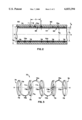
- FIG. 2 is a cross-sectional, longitudinal view of a longitudinal segment of the catheter of FIG. 1;
- FIG. 3 is a perspective view of a support structure of the segment of FIG. 2.
- FIG. 1 illustrates a catheter 10.
- the catheter 10 extends from a proximal end 12 to a distal end 14.
- a hub 16 is provided to be gripped by a physician as well as having an inlet 18 for injection of fluids into the catheter 10.
- a flexible hollow shaft 20 is connected to the hub 16.
- the shaft 20 is sized to be inserted into a patient's vasculature.
- the shaft 20 is commonly about 150 cm long.
- a strain relief jacket 22 connects the shaft 20 to the hub 16.
- the catheter 10 includes a segment 60 having the novel construction of the present invention.
- catheter is generally used to refer to the flexible shaft 20 of FIG. 1 having the segment 60 which a construction as will be described.
- the entire length of the catheter 10 can be constructed as will be described with reference to segment 60, it may be desirable to have a catheter 10 of multiple segments of different construction to impart different properties to different regions of the catheter 10 along its length. For example, it may be desirable to provide a catheter 10 having a proximal portion stiffer than a more flexible distal portion.
- the present invention is suitable for forming catheter segments of varying degrees of flexibility and other properties, the present invention is described with reference to a segment 60 of the length of the catheter 10. This is to allow for catheters where the entire length is constructed according to the teachings of this application as well as catheters where only a discrete portion is so constructed and where the remainder is constructed according to conventional catheter construction techniques.
- the segment 60 is shown to illustrate the novel construction.
- the segment 60 is a multi-layer construction including a flexible inner layer 62.
- the inner layer 62 is polytetraflouroethylene (PTFE) more commonly known by the trademark TeflonTM.
- PTFE polytetraflouroethylene
- layer 62 has an outer diameter D 1 of 0.0230 inch (0.58 mm) and an inner diameter D 2 of 0.0210 inch (0.53 mm) to define an internal bore 64 surrounded by the Teflon inner tube layer 62.
- the segment 60 also includes a novel support structure 70 as will be more fully described.
- the support structure 70 is generally tubular and is adhered to the external surface of the inner layer 62 by a thin bonding layer of any suitable adhesive 66 (e.g., polyurethane having a thickness T A of about 0.0004 inch or 0.01 mm).
- the support structure 70 has an outer diameter D 3 of about 0.025 inch (0.635 mm).
- an outer polymer jacket 90 Surrounding the exterior of the support structure 70, an outer polymer jacket 90 is provided.
- the outer jacket 90 may be any suitable flexible material for use in the vascular system. Such materials may be nylon or urethane.
- the outer jacket 90 has an outer diameter D 4 of 0.029 inch (0.74 mm).
- Applicants have provided a specific description of various layers of segment 60 as well as describing specific materials and dimensions. Such specificity has been given to describe a preferred embodiment of a specific catheter 10 utilizing the novel support structure 70 as will be described. More or fewer layers of materials could be used with structure 70 to impart desired properties (i.e., varying stiffness, strength, etc.) to segment 60. Similarly, specific materials and dimensions may be varied to alter the properties of segment 60.
- the support structure 70 includes a plurality of helical support struts 72a, 72b.
- the plurality of support struts includes first and second sets of struts. Struts of the first set are designated 72a while struts of the second set are designated 72b.
- support structure 70 is generally tubular and extends from a first end 74 to a second end 76.
- the support structure 70 surrounds the longitudinal axis X-X.
- the length of the support structure 70 e.g., the distance between ends 74, 76
- Each of the struts 72a, 72b extends from a first end 71a, 71b to a second end 73a, 73b.
- the first and second ends 71a, 73a and 71b, 73b of a strut 72a, 72b are spaced apart longitudinally with respect to axis X-X.
- each of the struts 72a, 72b curves around the axis X-X between ends 71a, 73a and 71b, 73b.
- the struts 72a, 72b are helical about axis X-X and curve substantially 360° about axis X-X.
- the struts 72a curve about axis X-X in a clockwise direction.
- Struts 72b curve in an opposite counter-clockwise direction.
- the struts 72a alternate in series with struts 72b along the length of the support structure 70. Adjacent ends 73a, 71b and 71a, 73b of adjacent struts 72a, 72b are connected such that all struts 72a, 72b along the length of support structure 70 are interconnected.
- a plurality of circumferential cylindrical rings or supports 78 are disposed between each of adjacent struts 72a, 72b. Accordingly, the adjacent ends 73a, 71b and 71a, 73b are not directly interconnected but, instead, are connected to opposite ends of a common circumferential support 78.
- the circumferential supports 78 and the struts 72a, 72b have a width W of about 0.003 inch (0.076 mm).
- the width is the dimension parallel to the axis X-X.
- the width is the dimension transverse to the helical path of the struts 72a, 72b.
- the circumferential supports 78 and the struts 72a, 72b have a thickness T of about 0.001 inch (0.025 mm) (i.e., the radial dimension measured between the inner and outer diameters of the circumferential supports 78 and the struts 72a, 72b).
- the circumferential supports 78 have an axial spacing S between opposing/adjacent supports 78 of about 0.005 inch (0.127 mm).
- the support structure 70 is fabricated from a solid blank of medical grade stainless steel tubing such that after such fabrication the supports 78 and struts 72a, 72b are integrally and continuously formed of uninterrupted metal.
- Other possible materials includes nickel-titanium alloys (e.g., nitinol) and cobalt-chromium-nickel alloys (e.g., ElgiloyTM alloy of Elgiloy, Inc. of Elgin, Ill., U.S.A.).
- Such a fabrication process includes starting with a rod (not shown) having an outer diameter equal to the desired inner diameter of the PTTE layer 62.
- the PTFE layer 62 is placed over the rod which acts as a jig to hold the elements of catheter 10 during fabrication.
- the adhesive 66 is applied to the external surface of PTFE layer 62.
- a solid tube of medical grade stainless steel (referred to as a hypotube) is then adhered to PTFE layer 62 by adhesive 66.
- the PTFE layer 62 and the metal tube can be assembled without the adhesive 66 with parts held in alignment until the final outer layer 90 is applied.
- the solid metal tube is then milled to remove excess material of the tube as waste and leaving only the material of the circumferential supports 78 and the struts 72a, 72b as the support structure 70.
- the metal tube is milled by a chemical milling process.
- a pattern mask of the desired pattern of the circumferential supports 78 and struts 72a, 72b is placed over the metal tube.
- a light source sensitizes a photoresist applied to the metal to create a pattern on the metal tube matching the mask.
- the photo-sensitized tube is then chemically etched to dissolve away the areas of the tube corresponding to the waste leaving only the desired material of the circumferential supports 78 and struts 72a, 72b.
- the outer layer 90 is applied to the outer surface of the support structure 70.
- the material of the outer layer 90 may, at the option of a designer, fill in the axial spacing S between the circumferential supports 78 or leave such spacing as voids to enhance flexibility.
- the rod is then removed from the PTFE layer 62 leaving a completed segment 60.
- the benefits of the present invention will be apparent to one of ordinary skill in the art.
- the present invention overcomes the disadvantage of prior art coil-construction catheters. Namely, in the case of a catheter formed with a single counter-clockwise coil (such as that shown in U.S. Pat. No. 5,178,158), such catheters would tend toward expansion or contraction in response to a clockwise or counter-clockwise torque, respectively, applied to the catheter. In addition to being urged to geometric deformation, such catheters would have a less reliable torque transmission response since at least a portion of the torque energy is wasted in geometric deformation.
- the combination of clockwise and counter-clockwise helical support struts result in the clockwise struts 72a and the counter-clockwise struts 72b urging toward expansion and contraction, respectively, in response to a counter-clockwise application of torque.
- the expansion and contraction forces tend to counter-act each other resulting in enhanced geometric integrity and enhanced torque transmission response.
- the prior art has used multiple coils for improving clockwise and counter-clockwise torque response as well as counter-acting expansion and contraction forces.
- Such designs apply an outer coil layer (e.g., a clockwise coil) surrounding an inner coil layer (e.g., a counter-clockwise coil). While such designs improve torque responsiveness, torque transmission responsiveness varies between clockwise and counter-clockwise applications of torque. Further, such designs have the added disadvantage of an additional layer of construction.
- a thin wall catheter is a significant design constraint due to the extremely small vessels through which the catheter is to pass and the desire to maximize the diameter of the internal bore of the catheter and to make the catheter extremely flexible.
- the clockwise and counter-clockwise helical struts 72a, 72b reside in the same layer and have the same diameters.
- the present invention also permits incorporation of the circumferential supports 78.
- These rings 78 increase the burst strength of the catheter 10 when used to infuse drugs or other media at high pressure (i.e., 300 psi).
- the rings 78 are reinforcing members resisting radial expansion forces urging the catheter toward expansion. Further, the rings 78 resist geometric deformation of the internal cross-section of the catheter 10 at the rings 78. Further, the benefits of the rings 78 are achieved in a design without needing an additional layer of material to accommodate the rings 78. Namely, the rings 78 reside in the same layer and have the same diameters as the support struts 72a, 72b.
- the support structure 70 need not be formed of metal or fabricated in the chemical milling manner indicated.
- the support structure 70 can be formed from any structural material in any manner including, without limitation, electrical discharge machining, laser cutting, or assembly of individual components.
- cicumferential support rings 78 can be omitted where burst strength is not an issue (in which case, the struts 72a, 72b are directly interconnected).
- the geometry of the support rings can be varied (e.g., thicker, wider, narrower, closer or more distant spacing as well as nonsymmetrical shapes compared to the symmetrical shapes shown) to vary strength and flexibility.
- helical struts 72a, 72b are shown in an alternating series, such an arrangement can be modified (e.g., a series of multiple clockwise struts 72a followed by one or a series of multiple counter-clockwise struts 72b or other such variations in the pattern of the series of struts 72) to control torque transmission response or stiffness.
- the shape of the helical struts 72 can be modified. For example, the tightness of the coiling of the struts, the amount of bending of the struts (i.g., greater or less than the 360° bending shown per strut 72a, 72b) can be modified to control the torque transmission response as well as the stiffness of the catheter.
- the relative positioning of the connected ends (e.g., ends 71b and 73a) of adjacent struts 72a, 72b can be varied.
- the ends 71b and 73a are positioned on diametrically opposite sides of a ring 78.
- the ends 71b and 73a could be positioned in direct opposition on a ring 78 or any other relative positioning to control stiffness of the catheter.
- the present invention has been disclosed in a preferred embodiment.
- the invention permits construction of a catheter overcoming disadvantages of prior designs as well as providing a structure having various features which can be modified to design catheters with optimum performance for a wide variety of applications. It is intended that modifications and equivalents of the disclosed concepts, such as those which readily occur to one of skill in the art shall be included within the scope of the claims appended hereto.
Abstract
Description
Claims (15)
Priority Applications (3)
| Application Number | Priority Date | Filing Date | Title |
|---|---|---|---|
| US08/985,810 US6033394A (en) | 1997-12-05 | 1997-12-05 | Catheter support structure |
| PCT/US1998/018323 WO1999029361A1 (en) | 1997-12-05 | 1998-09-03 | Catheter support structure |
| AU92185/98A AU9218598A (en) | 1997-12-05 | 1998-09-03 | Catheter support structure |
Applications Claiming Priority (1)
| Application Number | Priority Date | Filing Date | Title |
|---|---|---|---|
| US08/985,810 US6033394A (en) | 1997-12-05 | 1997-12-05 | Catheter support structure |
Publications (1)
| Publication Number | Publication Date |
|---|---|
| US6033394A true US6033394A (en) | 2000-03-07 |
Family
ID=25531815
Family Applications (1)
| Application Number | Title | Priority Date | Filing Date |
|---|---|---|---|
| US08/985,810 Expired - Lifetime US6033394A (en) | 1997-12-05 | 1997-12-05 | Catheter support structure |
Country Status (3)
| Country | Link |
|---|---|
| US (1) | US6033394A (en) |
| AU (1) | AU9218598A (en) |
| WO (1) | WO1999029361A1 (en) |
Cited By (68)
| Publication number | Priority date | Publication date | Assignee | Title |
|---|---|---|---|---|
| US20020082585A1 (en) * | 1999-06-15 | 2002-06-27 | Sean Carroll | Defined deflection structure |
| US6585718B2 (en) | 2001-05-02 | 2003-07-01 | Cardiac Pacemakers, Inc. | Steerable catheter with shaft support system for resisting axial compressive loads |
| US6585717B1 (en) * | 1999-06-15 | 2003-07-01 | Cryocath Technologies Inc. | Deflection structure |
| US6723335B1 (en) | 2000-04-07 | 2004-04-20 | Jeffrey William Moehlenbruck | Methods and compositions for treating intervertebral disc degeneration |
| US20040134491A1 (en) * | 2002-12-30 | 2004-07-15 | Quiescence Medical | Apparatus and methods for treating sleep apnea |
| US6786876B2 (en) | 2001-06-20 | 2004-09-07 | Microvention, Inc. | Medical devices having full or partial polymer coatings and their methods of manufacture |
| US20050150085A1 (en) * | 2004-01-14 | 2005-07-14 | Jane Pak | Fastener for attaching a button to a piece of fabric or garment |
| US20050195279A1 (en) * | 2002-07-18 | 2005-09-08 | Andrew Wesley Hobgood | Method for using a wireless motorized camera mount for tracking in augmented reality |
| US20060089704A1 (en) * | 2004-10-25 | 2006-04-27 | Myles Douglas | Vascular graft and deployment system |
| US20060178726A1 (en) * | 2004-10-25 | 2006-08-10 | Myles Douglas | Vascular graft and deployment system |
| US20060184105A1 (en) * | 2005-02-15 | 2006-08-17 | Townsend Gregory L | Thin wall catheter and method of placing same |
| US20060235458A1 (en) * | 2005-04-15 | 2006-10-19 | Amir Belson | Instruments having an external working channel |
| US20070168013A1 (en) * | 2006-01-19 | 2007-07-19 | Myles Douglas | Vascular graft and deployment system |
| US20070185500A1 (en) * | 2006-02-03 | 2007-08-09 | Martin Brian B | Devices for restoring blood flow within blocked vasculature |
| US20080035158A1 (en) * | 2003-07-22 | 2008-02-14 | Pflueger D R | Apparatus and Methods for Treating Sleep Apnea |
| US20080051873A1 (en) * | 2006-07-20 | 2008-02-28 | Orbusneich Medical, Inc. | Bioabsorbable polymeric medical device |
| US20080051868A1 (en) * | 2006-07-20 | 2008-02-28 | Orbusneich Medical, Inc. | Bioabsorbable Polymeric Medical Device |
| US20080097575A1 (en) * | 2006-10-20 | 2008-04-24 | Orbusneich Medical, Inc. | Bioabsorbable Medical Device with Coating |
| US20080118546A1 (en) * | 2006-07-20 | 2008-05-22 | Orbusneich Medical, Inc. | Bioabsorbable polymeric composition for a medical device |
| US7381222B2 (en) | 2002-12-30 | 2008-06-03 | Quiescence Medical, Inc. | Stent for maintaining patency of a body region |
| US20080206440A1 (en) * | 2006-10-20 | 2008-08-28 | Orbusneich Medical, Inc. | Bioabsorbable Polymeric Composition and Medical Device Background |
| US20080262532A1 (en) * | 2007-04-17 | 2008-10-23 | Lazarus Effect, Inc. | Complex wire formed devices |
| US20090299393A1 (en) * | 2007-12-26 | 2009-12-03 | Lazarus Effect, Inc. | Retrieval systems and methods for use thereof |
| US7647931B2 (en) | 2002-12-30 | 2010-01-19 | Quiescence Medical, Inc. | Stent for maintaining patency of a body region |
| US20100093946A1 (en) * | 2008-10-11 | 2010-04-15 | Orbusneich Medical, Inc. | Bioabsorbable Polymeric Compositions and Medical Devices |
| US20100094405A1 (en) * | 2008-10-10 | 2010-04-15 | Orbusneich Medical, Inc. | Bioabsorbable Polymeric Medical Device |
| US20100139465A1 (en) * | 2008-12-08 | 2010-06-10 | Next Vascular, Llc | Micro-Cutting Machine for Forming Cuts in Products |
| US20100256603A1 (en) * | 2009-04-03 | 2010-10-07 | Scientia Vascular, Llc | Micro-fabricated Catheter Devices Formed Having Elastomeric Fill Compositions |
| US20100256602A1 (en) * | 2009-04-03 | 2010-10-07 | Scientia Vascular, Llc | Micro-fabricated Guidewire Devices Formed With Hybrid Materials |
| US20100256605A1 (en) * | 2009-04-03 | 2010-10-07 | Scientia Vascular, Llc | Micro-fabricated Catheter Devices Formed With Hybrid Materials |
| US20100256528A1 (en) * | 2009-04-03 | 2010-10-07 | Scientia Vascular, Llc | Micro-fabricated Guidewire Devices Having Varying Diameters |
| US20100256606A1 (en) * | 2009-04-03 | 2010-10-07 | Scientia Vascular, Llc | Micro-fabricated Guidewire Devices Formed Having Elastomeric Fill Compositions |
| US20100256604A1 (en) * | 2009-04-03 | 2010-10-07 | Scientia Vascular, Llc | Micro-fabricated Catheter Devices Formed Having Elastomeric Compositions |
| US7892186B2 (en) | 2005-12-09 | 2011-02-22 | Heraeus Materials S.A. | Handle and articulator system and method |
| WO2011056311A1 (en) * | 2009-11-09 | 2011-05-12 | St. Jude Medical, Atrial Fibrillation Division, Inc. | Device for reducing axial shortening of catheter or sheath due to repeated deflection |
| US20110130822A1 (en) * | 2007-07-20 | 2011-06-02 | Orbusneich Medical, Inc. | Bioabsorbable Polymeric Compositions and Medical Devices |
| US8034045B1 (en) | 2010-05-05 | 2011-10-11 | Cook Medical Technologies Llc | Flexible sheath |
| US20140207115A1 (en) * | 2004-01-28 | 2014-07-24 | Applied Medical Resources Corporation | Medical tubing having variable characteristcs and method of making same |
| US8795305B2 (en) | 2011-05-23 | 2014-08-05 | Lazarus Effect, Inc. | Retrieval systems and methods for use thereof |
| US8801748B2 (en) | 2010-01-22 | 2014-08-12 | Lazarus Effect, Inc. | Retrieval systems and methods for use thereof |
| US9254371B2 (en) | 2009-03-06 | 2016-02-09 | Lazarus Effect, Inc. | Retrieval systems and methods for use thereof |
| US9265649B2 (en) | 2010-12-13 | 2016-02-23 | Quiescence Medical, Inc. | Apparatus and methods for treating sleep apnea |
| US9616195B2 (en) | 2009-04-03 | 2017-04-11 | Scientia Vascular, Llc | Micro-fabricated catheter devices having varying diameters |
| US9795765B2 (en) | 2010-04-09 | 2017-10-24 | St. Jude Medical International Holding S.À R.L. | Variable stiffness steering mechanism for catheters |
| US9855404B2 (en) | 2013-05-03 | 2018-01-02 | St. Jude Medical International Holding S.À R.L. | Dual bend radii steering catheter |
| EP3284501A1 (en) * | 2009-04-03 | 2018-02-21 | Scientia Vascular, LLC | Guidewires and catheters for use in surgical procedures |
| US9924958B2 (en) | 2010-07-15 | 2018-03-27 | Covidien Lp | Retrieval systems and methods for use thereof |
| US10064635B2 (en) | 2007-04-17 | 2018-09-04 | Covidien Lp | Articulating retrieval devices |
| US10076346B2 (en) | 2007-04-17 | 2018-09-18 | Covidien Lp | Complex wire formed devices |
| US10350094B2 (en) | 2013-03-11 | 2019-07-16 | Microvention, Inc. | Implantable device with adhesive properties |
| US10456560B2 (en) | 2015-02-11 | 2019-10-29 | Covidien Lp | Expandable tip medical devices and methods |
| US10478322B2 (en) | 2017-06-19 | 2019-11-19 | Covidien Lp | Retractor device for transforming a retrieval device from a deployed position to a delivery position |
| US10575864B2 (en) | 2017-06-22 | 2020-03-03 | Covidien Lp | Securing element for resheathing an intravascular device and associated systems and methods |
| US10709464B2 (en) | 2017-05-12 | 2020-07-14 | Covidien Lp | Retrieval of material from vessel lumens |
| US10722257B2 (en) | 2017-05-12 | 2020-07-28 | Covidien Lp | Retrieval of material from vessel lumens |
| US10821268B2 (en) | 2016-09-14 | 2020-11-03 | Scientia Vascular, Llc | Integrated coil vascular devices |
| US10945746B2 (en) | 2017-06-12 | 2021-03-16 | Covidien Lp | Tools for sheathing treatment devices and associated systems and methods |
| US10953203B2 (en) | 2016-07-18 | 2021-03-23 | Scientia Vascular, Llc | Guidewire devices having shapeable polymer tips |
| US11052228B2 (en) | 2016-07-18 | 2021-07-06 | Scientia Vascular, Llc | Guidewire devices having shapeable tips and bypass cuts |
| US11129630B2 (en) | 2017-05-12 | 2021-09-28 | Covidien Lp | Retrieval of material from vessel lumens |
| US11191555B2 (en) | 2017-05-12 | 2021-12-07 | Covidien Lp | Retrieval of material from vessel lumens |
| US11202646B2 (en) | 2007-04-17 | 2021-12-21 | Covidien Lp | Articulating retrieval devices |
| US11298145B2 (en) | 2017-05-12 | 2022-04-12 | Covidien Lp | Retrieval of material from vessel lumens |
| US11305095B2 (en) | 2018-02-22 | 2022-04-19 | Scientia Vascular, Llc | Microfabricated catheter having an intermediate preferred bending section |
| US11369351B2 (en) | 2017-05-26 | 2022-06-28 | Scientia Vascular, Inc. | Micro-fabricated medical device having a non-helical cut arrangement |
| US11406791B2 (en) | 2009-04-03 | 2022-08-09 | Scientia Vascular, Inc. | Micro-fabricated guidewire devices having varying diameters |
| US11452541B2 (en) | 2016-12-22 | 2022-09-27 | Scientia Vascular, Inc. | Intravascular device having a selectively deflectable tip |
| US11951267B2 (en) | 2021-06-01 | 2024-04-09 | Scientia Vascular, Inc. | Guidewire devices having shapeable tips and bypass cuts |
Families Citing this family (3)
| Publication number | Priority date | Publication date | Assignee | Title |
|---|---|---|---|---|
| US6022343A (en) | 1998-09-03 | 2000-02-08 | Intratherapeutics, Inc. | Bridged coil catheter support structure |
| CN115253015B (en) | 2017-12-20 | 2023-04-25 | 泰尔茂株式会社 | Catheter assembly |
| JP2024500990A (en) * | 2020-12-29 | 2024-01-10 | ストライカー コーポレイション | Medical device with tubular reinforcement |
Citations (14)
| Publication number | Priority date | Publication date | Assignee | Title |
|---|---|---|---|---|
| EP0369383A1 (en) * | 1988-11-14 | 1990-05-23 | Cordis Corporation | Catheter having sections of variable torsion characteristics |
| EP0692276A2 (en) * | 1994-07-11 | 1996-01-17 | Terumo Kabushiki Kaisha | Catheter tube and a method of processing the inner surface of a tube |
| WO1996028208A1 (en) * | 1995-03-14 | 1996-09-19 | Mallinckrodt Medical, Inc. | Catheters with reinforced filaments |
| WO1996033763A2 (en) * | 1995-04-28 | 1996-10-31 | Target Therapeutics, Inc. | High performance braided catheter |
| WO1996038193A1 (en) * | 1995-05-31 | 1996-12-05 | Cardia Catheter Co. | Flexible tubular device for use in medical applications |
| US5702373A (en) * | 1995-08-31 | 1997-12-30 | Target Therapeutics, Inc. | Composite super-elastic alloy braid reinforced catheter |
| US5795341A (en) * | 1994-11-10 | 1998-08-18 | Target Therapeutics, Inc. | High performance spiral-wound catheter |
| US5827242A (en) * | 1996-06-21 | 1998-10-27 | Medtronic, Inc. | Reinforced catheter body and method for its fabrication |
| US5843168A (en) * | 1997-03-31 | 1998-12-01 | Medtronic, Inc. | Double wave stent with strut |
| US5846246A (en) * | 1994-10-21 | 1998-12-08 | Cordis Corporation | Dual-balloon rapid-exchange stent delivery catheter with guidewire channel |
| US5849034A (en) * | 1992-03-19 | 1998-12-15 | Medtronic, Inc. | Intraluminal stent |
| US5868783A (en) * | 1997-04-16 | 1999-02-09 | Numed, Inc. | Intravascular stent with limited axial shrinkage |
| US5868782A (en) * | 1996-12-24 | 1999-02-09 | Global Therapeutics, Inc. | Radially expandable axially non-contracting surgical stent |
| US5891108A (en) * | 1994-09-12 | 1999-04-06 | Cordis Corporation | Drug delivery stent |
Family Cites Families (2)
| Publication number | Priority date | Publication date | Assignee | Title |
|---|---|---|---|---|
| US5178158A (en) | 1990-10-29 | 1993-01-12 | Boston Scientific Corporation | Convertible guidewire-catheter with soft tip |
| US5960340A (en) | 1996-02-28 | 1999-09-28 | At&T Corporation | Automatic cellular telephone registration for universal telephone number service |
-
1997
- 1997-12-05 US US08/985,810 patent/US6033394A/en not_active Expired - Lifetime
-
1998
- 1998-09-03 AU AU92185/98A patent/AU9218598A/en not_active Abandoned
- 1998-09-03 WO PCT/US1998/018323 patent/WO1999029361A1/en active Application Filing
Patent Citations (14)
| Publication number | Priority date | Publication date | Assignee | Title |
|---|---|---|---|---|
| EP0369383A1 (en) * | 1988-11-14 | 1990-05-23 | Cordis Corporation | Catheter having sections of variable torsion characteristics |
| US5849034A (en) * | 1992-03-19 | 1998-12-15 | Medtronic, Inc. | Intraluminal stent |
| EP0692276A2 (en) * | 1994-07-11 | 1996-01-17 | Terumo Kabushiki Kaisha | Catheter tube and a method of processing the inner surface of a tube |
| US5891108A (en) * | 1994-09-12 | 1999-04-06 | Cordis Corporation | Drug delivery stent |
| US5846246A (en) * | 1994-10-21 | 1998-12-08 | Cordis Corporation | Dual-balloon rapid-exchange stent delivery catheter with guidewire channel |
| US5795341A (en) * | 1994-11-10 | 1998-08-18 | Target Therapeutics, Inc. | High performance spiral-wound catheter |
| WO1996028208A1 (en) * | 1995-03-14 | 1996-09-19 | Mallinckrodt Medical, Inc. | Catheters with reinforced filaments |
| WO1996033763A2 (en) * | 1995-04-28 | 1996-10-31 | Target Therapeutics, Inc. | High performance braided catheter |
| WO1996038193A1 (en) * | 1995-05-31 | 1996-12-05 | Cardia Catheter Co. | Flexible tubular device for use in medical applications |
| US5702373A (en) * | 1995-08-31 | 1997-12-30 | Target Therapeutics, Inc. | Composite super-elastic alloy braid reinforced catheter |
| US5827242A (en) * | 1996-06-21 | 1998-10-27 | Medtronic, Inc. | Reinforced catheter body and method for its fabrication |
| US5868782A (en) * | 1996-12-24 | 1999-02-09 | Global Therapeutics, Inc. | Radially expandable axially non-contracting surgical stent |
| US5843168A (en) * | 1997-03-31 | 1998-12-01 | Medtronic, Inc. | Double wave stent with strut |
| US5868783A (en) * | 1997-04-16 | 1999-02-09 | Numed, Inc. | Intravascular stent with limited axial shrinkage |
Cited By (151)
| Publication number | Priority date | Publication date | Assignee | Title |
|---|---|---|---|---|
| US20020082585A1 (en) * | 1999-06-15 | 2002-06-27 | Sean Carroll | Defined deflection structure |
| US6585717B1 (en) * | 1999-06-15 | 2003-07-01 | Cryocath Technologies Inc. | Deflection structure |
| US6890329B2 (en) * | 1999-06-15 | 2005-05-10 | Cryocath Technologies Inc. | Defined deflection structure |
| US6723335B1 (en) | 2000-04-07 | 2004-04-20 | Jeffrey William Moehlenbruck | Methods and compositions for treating intervertebral disc degeneration |
| US7556649B2 (en) | 2000-04-07 | 2009-07-07 | Zimmer Orthobiologics, Inc. | Methods and compositions for treating intervertebral disc degeneration |
| US20050002909A1 (en) * | 2000-04-07 | 2005-01-06 | Centerpulse Biologics Inc | Methods and compositions for treating intervertebral disc degeneration |
| US6585718B2 (en) | 2001-05-02 | 2003-07-01 | Cardiac Pacemakers, Inc. | Steerable catheter with shaft support system for resisting axial compressive loads |
| US6786876B2 (en) | 2001-06-20 | 2004-09-07 | Microvention, Inc. | Medical devices having full or partial polymer coatings and their methods of manufacture |
| US20050004560A1 (en) * | 2001-06-20 | 2005-01-06 | Microvention, Inc. | Medical devices having full or partial polymer coatings and their methods of manufacture |
| US7494687B2 (en) | 2001-06-20 | 2009-02-24 | Microvention, Inc. | Medical devices having full or partial polymer coatings and their methods of manufacture |
| WO2003037416A1 (en) * | 2001-11-01 | 2003-05-08 | Sean Carroll | Defined deflection structure |
| US20050195279A1 (en) * | 2002-07-18 | 2005-09-08 | Andrew Wesley Hobgood | Method for using a wireless motorized camera mount for tracking in augmented reality |
| US8939145B2 (en) | 2002-12-30 | 2015-01-27 | Quiescence Medical, Inc. | Apparatus and methods for treating sleep apnea |
| US20040134491A1 (en) * | 2002-12-30 | 2004-07-15 | Quiescence Medical | Apparatus and methods for treating sleep apnea |
| US7381222B2 (en) | 2002-12-30 | 2008-06-03 | Quiescence Medical, Inc. | Stent for maintaining patency of a body region |
| US8104478B2 (en) | 2002-12-30 | 2012-01-31 | Quiescence Medical, Inc. | Apparatus and methods for treating sleep apnea |
| US8578938B2 (en) | 2002-12-30 | 2013-11-12 | Quiescence Medical, Inc. | Apparatus and methods for treating sleep apnea |
| US20050199248A1 (en) * | 2002-12-30 | 2005-09-15 | Quiescence Medical, Inc. | Apparatus and methods for treating sleep apnea |
| US7647931B2 (en) | 2002-12-30 | 2010-01-19 | Quiescence Medical, Inc. | Stent for maintaining patency of a body region |
| US20100000550A1 (en) * | 2002-12-30 | 2010-01-07 | Quiescence Medical, Inc. | Apparatus and methods for treating sleep apnea |
| US7992566B2 (en) | 2002-12-30 | 2011-08-09 | Quiescence Medical, Inc. | Apparatus and methods for treating sleep apnea |
| US20080035158A1 (en) * | 2003-07-22 | 2008-02-14 | Pflueger D R | Apparatus and Methods for Treating Sleep Apnea |
| US8146600B2 (en) | 2003-07-22 | 2012-04-03 | Quiescence Medical, Inc. | Apparatus and methods for treating sleep apnea |
| US20050150085A1 (en) * | 2004-01-14 | 2005-07-14 | Jane Pak | Fastener for attaching a button to a piece of fabric or garment |
| US20140207115A1 (en) * | 2004-01-28 | 2014-07-24 | Applied Medical Resources Corporation | Medical tubing having variable characteristcs and method of making same |
| US9987460B2 (en) * | 2004-01-28 | 2018-06-05 | Applied Medical Resources Corporation | Medical tubing having variable characteristcs and method of making same |
| US20060089704A1 (en) * | 2004-10-25 | 2006-04-27 | Myles Douglas | Vascular graft and deployment system |
| US20060178726A1 (en) * | 2004-10-25 | 2006-08-10 | Myles Douglas | Vascular graft and deployment system |
| US7699883B2 (en) * | 2004-10-25 | 2010-04-20 | Myles Douglas | Vascular graft and deployment system |
| US20060184105A1 (en) * | 2005-02-15 | 2006-08-17 | Townsend Gregory L | Thin wall catheter and method of placing same |
| US20060235458A1 (en) * | 2005-04-15 | 2006-10-19 | Amir Belson | Instruments having an external working channel |
| WO2006113544A3 (en) * | 2005-04-15 | 2009-05-22 | Amir Belson | Instruments having an external working channel |
| US7892186B2 (en) | 2005-12-09 | 2011-02-22 | Heraeus Materials S.A. | Handle and articulator system and method |
| WO2007084724A3 (en) * | 2006-01-19 | 2008-11-13 | Myles Douglas | Vascular graft and deployment system |
| US20070168013A1 (en) * | 2006-01-19 | 2007-07-19 | Myles Douglas | Vascular graft and deployment system |
| US20070197103A1 (en) * | 2006-02-03 | 2007-08-23 | Martin Brian B | Devices for restoring blood flow within blocked vasculature |
| US10806473B2 (en) | 2006-02-03 | 2020-10-20 | Covidien Lp | Methods for restoring blood flow within blocked vasculature |
| US11596426B2 (en) | 2006-02-03 | 2023-03-07 | Covidien Lp | Methods for restoring blood flow within blocked vasculature |
| US9931128B2 (en) | 2006-02-03 | 2018-04-03 | Covidien Lp | Methods for restoring blood flow within blocked vasculature |
| US20070225749A1 (en) * | 2006-02-03 | 2007-09-27 | Martin Brian B | Methods and devices for restoring blood flow within blocked vasculature |
| US20070198029A1 (en) * | 2006-02-03 | 2007-08-23 | Martin Brian B | Methods for restoring blood flow within blocked vasculature |
| US20070198030A1 (en) * | 2006-02-03 | 2007-08-23 | Martin Brian B | Methods for restoring blood flow within blocked vasculature |
| US20070185501A1 (en) * | 2006-02-03 | 2007-08-09 | Martin Brian B | Devices for restoring blood flow within blocked vasculature |
| US20070185500A1 (en) * | 2006-02-03 | 2007-08-09 | Martin Brian B | Devices for restoring blood flow within blocked vasculature |
| US20080118546A1 (en) * | 2006-07-20 | 2008-05-22 | Orbusneich Medical, Inc. | Bioabsorbable polymeric composition for a medical device |
| US7846197B2 (en) | 2006-07-20 | 2010-12-07 | Orbusneich Medical, Inc. | Bioabsorbable polymeric medical device |
| US20090240317A1 (en) * | 2006-07-20 | 2009-09-24 | Orbusneich Medical, Inc. | Bioabsorbable Polymeric Medical Device |
| US9642947B2 (en) | 2006-07-20 | 2017-05-09 | Orbusneich Medical, Inc. | Bioabsorbable polymeric composition for a medical device |
| US9642945B2 (en) | 2006-07-20 | 2017-05-09 | Orbusneich Medical, Inc. | Bioabsorbable polymeric composition for a medical device |
| US9629940B2 (en) | 2006-07-20 | 2017-04-25 | Orbusneich Medical, Inc. | Bioabsorbable polymeric composition for a medical device |
| US20080051873A1 (en) * | 2006-07-20 | 2008-02-28 | Orbusneich Medical, Inc. | Bioabsorbable polymeric medical device |
| US20080051874A1 (en) * | 2006-07-20 | 2008-02-28 | Orbusneich Medical, Inc. | Bioabsorbable Polymeric Medical Device |
| US8460364B2 (en) | 2006-07-20 | 2013-06-11 | Orbusneich Medical, Inc. | Bioabsorbable polymeric medical device |
| US8460362B2 (en) | 2006-07-20 | 2013-06-11 | Orbusneich Medical, Inc. | Bioabsorbable polymeric medical device |
| US20080051868A1 (en) * | 2006-07-20 | 2008-02-28 | Orbusneich Medical, Inc. | Bioabsorbable Polymeric Medical Device |
| US7833260B2 (en) | 2006-07-20 | 2010-11-16 | Orbusneich Medical, Inc. | Bioabsorbable polymeric medical device |
| US7846361B2 (en) | 2006-07-20 | 2010-12-07 | Orbusneich Medical, Inc. | Bioabsorbable polymeric composition for a medical device |
| US9662416B2 (en) | 2006-07-20 | 2017-05-30 | Orbusneich Medical, Inc. | Bioabsorbable polymeric composition for a medical device |
| US20080051875A1 (en) * | 2006-07-20 | 2008-02-28 | Orbusneich Medical, Inc. | Bioabsorbable Polymeric Medical Device |
| US20080097576A1 (en) * | 2006-10-20 | 2008-04-24 | Orbusneich Medical, Inc. | Bioabsorbable Polymeric Medical Device |
| US8691321B2 (en) | 2006-10-20 | 2014-04-08 | Orbusneich Medical, Inc. | Bioabsorbable polymeric composition and medical device background |
| US20080097575A1 (en) * | 2006-10-20 | 2008-04-24 | Orbusneich Medical, Inc. | Bioabsorbable Medical Device with Coating |
| US7959942B2 (en) | 2006-10-20 | 2011-06-14 | Orbusneich Medical, Inc. | Bioabsorbable medical device with coating |
| US20080206440A1 (en) * | 2006-10-20 | 2008-08-28 | Orbusneich Medical, Inc. | Bioabsorbable Polymeric Composition and Medical Device Background |
| US8535334B2 (en) | 2007-04-17 | 2013-09-17 | Lazarus Effect, Inc. | Complex wire formed devices |
| US20080262528A1 (en) * | 2007-04-17 | 2008-10-23 | Lazarus Effect, Inc. | Complex wire formed devices |
| US11617593B2 (en) | 2007-04-17 | 2023-04-04 | Covidien Lp | Complex wire formed devices |
| US20080262532A1 (en) * | 2007-04-17 | 2008-10-23 | Lazarus Effect, Inc. | Complex wire formed devices |
| US10064635B2 (en) | 2007-04-17 | 2018-09-04 | Covidien Lp | Articulating retrieval devices |
| US11202646B2 (en) | 2007-04-17 | 2021-12-21 | Covidien Lp | Articulating retrieval devices |
| US9271747B2 (en) | 2007-04-17 | 2016-03-01 | Lazarus Effect, Inc. | Complex wire formed devices |
| US9271748B2 (en) | 2007-04-17 | 2016-03-01 | Lazarus Effect, Inc. | Complex wire formed devices |
| US8512352B2 (en) | 2007-04-17 | 2013-08-20 | Lazarus Effect, Inc. | Complex wire formed devices |
| US10925625B2 (en) | 2007-04-17 | 2021-02-23 | Covidien Lp | Complex wire formed devices |
| US10076346B2 (en) | 2007-04-17 | 2018-09-18 | Covidien Lp | Complex wire formed devices |
| US20110130822A1 (en) * | 2007-07-20 | 2011-06-02 | Orbusneich Medical, Inc. | Bioabsorbable Polymeric Compositions and Medical Devices |
| US11376027B2 (en) | 2007-12-26 | 2022-07-05 | Covidien Lp | Retrieval systems and methods for use thereof |
| US9717514B2 (en) | 2007-12-26 | 2017-08-01 | Covidien Lp | Retrieval systems and methods for use thereof |
| US8545526B2 (en) | 2007-12-26 | 2013-10-01 | Lazarus Effect, Inc. | Retrieval systems and methods for use thereof |
| US20090299393A1 (en) * | 2007-12-26 | 2009-12-03 | Lazarus Effect, Inc. | Retrieval systems and methods for use thereof |
| US20100094405A1 (en) * | 2008-10-10 | 2010-04-15 | Orbusneich Medical, Inc. | Bioabsorbable Polymeric Medical Device |
| US20100093946A1 (en) * | 2008-10-11 | 2010-04-15 | Orbusneich Medical, Inc. | Bioabsorbable Polymeric Compositions and Medical Devices |
| US10980968B2 (en) | 2008-12-08 | 2021-04-20 | Scientia Vascular, Llc | Micro-cutting systems for forming cuts in products |
| US10232141B2 (en) | 2008-12-08 | 2019-03-19 | Scientia Vascular, Llc | Micro-cutting systems for forming cuts in products |
| US9662798B2 (en) | 2008-12-08 | 2017-05-30 | Scientia Vascular Llc | Micro-cutting systems for forming cuts in products |
| US20100139465A1 (en) * | 2008-12-08 | 2010-06-10 | Next Vascular, Llc | Micro-Cutting Machine for Forming Cuts in Products |
| US8468919B2 (en) | 2008-12-08 | 2013-06-25 | Next Vascular, Llc | Micro-cutting machine for forming cuts in products |
| US10172633B2 (en) | 2009-03-06 | 2019-01-08 | Covidien Lp | Retrieval systems and methods for use thereof |
| US9254371B2 (en) | 2009-03-06 | 2016-02-09 | Lazarus Effect, Inc. | Retrieval systems and methods for use thereof |
| US9067332B2 (en) | 2009-04-03 | 2015-06-30 | Scientia Vascular, Llc | Micro-fabricated catheter devices formed with hybrid materials |
| US9950137B2 (en) | 2009-04-03 | 2018-04-24 | Scientia Vascular, Llc | Micro-fabricated guidewire devices formed with hybrid materials |
| US20100256604A1 (en) * | 2009-04-03 | 2010-10-07 | Scientia Vascular, Llc | Micro-fabricated Catheter Devices Formed Having Elastomeric Compositions |
| US20100256606A1 (en) * | 2009-04-03 | 2010-10-07 | Scientia Vascular, Llc | Micro-fabricated Guidewire Devices Formed Having Elastomeric Fill Compositions |
| US9616195B2 (en) | 2009-04-03 | 2017-04-11 | Scientia Vascular, Llc | Micro-fabricated catheter devices having varying diameters |
| US20100256602A1 (en) * | 2009-04-03 | 2010-10-07 | Scientia Vascular, Llc | Micro-fabricated Guidewire Devices Formed With Hybrid Materials |
| US20100256603A1 (en) * | 2009-04-03 | 2010-10-07 | Scientia Vascular, Llc | Micro-fabricated Catheter Devices Formed Having Elastomeric Fill Compositions |
| US9072873B2 (en) | 2009-04-03 | 2015-07-07 | Scientia Vascular, Llc | Micro-fabricated guidewire devices having elastomeric compositions |
| US10363389B2 (en) | 2009-04-03 | 2019-07-30 | Scientia Vascular, Llc | Micro-fabricated guidewire devices having varying diameters |
| US9067333B2 (en) | 2009-04-03 | 2015-06-30 | Scientia Vascular, Llc | Micro-fabricated guidewire devices having elastomeric fill compositions |
| US20100256605A1 (en) * | 2009-04-03 | 2010-10-07 | Scientia Vascular, Llc | Micro-fabricated Catheter Devices Formed With Hybrid Materials |
| US20100256528A1 (en) * | 2009-04-03 | 2010-10-07 | Scientia Vascular, Llc | Micro-fabricated Guidewire Devices Having Varying Diameters |
| US11406791B2 (en) | 2009-04-03 | 2022-08-09 | Scientia Vascular, Inc. | Micro-fabricated guidewire devices having varying diameters |
| EP3284501A1 (en) * | 2009-04-03 | 2018-02-21 | Scientia Vascular, LLC | Guidewires and catheters for use in surgical procedures |
| US20100256527A1 (en) * | 2009-04-03 | 2010-10-07 | Scientia Vascular, Llc | Micro-fabricated Guidewire Devices Formed Having Elastomeric Compositions |
| US20110112476A1 (en) * | 2009-11-09 | 2011-05-12 | Kauphusman James V | Device for reducing axial shortening of catheter or sheath due to repeated deflection |
| WO2011056311A1 (en) * | 2009-11-09 | 2011-05-12 | St. Jude Medical, Atrial Fibrillation Division, Inc. | Device for reducing axial shortening of catheter or sheath due to repeated deflection |
| US9486612B2 (en) | 2009-11-09 | 2016-11-08 | St. Jude Medical, Atrial Fibrillation Division, Inc. | Device for reducing axial shortening of catheter or sheath due to repeated deflection |
| CN102548603B (en) * | 2009-11-09 | 2014-10-22 | 圣犹达医疗用品电生理部门有限公司 | Device for reducing axial shortening of catheter or sheath due to repeated deflection |
| US8376991B2 (en) | 2009-11-09 | 2013-02-19 | St. Jude Medical, Atrial Fibrillation Division, Inc. | Device for reducing axial shortening of catheter or sheath due to repeated deflection |
| CN102548603A (en) * | 2009-11-09 | 2012-07-04 | 圣犹达医疗用品电生理部门有限公司 | Device for reducing axial shortening of catheter or sheath due to repeated deflection |
| JP2013509946A (en) * | 2009-11-09 | 2013-03-21 | セント・ジュード・メディカル・エイトリアル・フィブリレーション・ディヴィジョン・インコーポレーテッド | Device for reducing axial contraction of catheter or sheath due to repeated bending |
| US10675444B2 (en) | 2009-11-09 | 2020-06-09 | St. Jude Medical, Atrial Fibrillation Division, Inc. | Device for reducing axial shortening of catheter or sheath due to repeated deflection |
| US8801748B2 (en) | 2010-01-22 | 2014-08-12 | Lazarus Effect, Inc. | Retrieval systems and methods for use thereof |
| US9795765B2 (en) | 2010-04-09 | 2017-10-24 | St. Jude Medical International Holding S.À R.L. | Variable stiffness steering mechanism for catheters |
| US8034045B1 (en) | 2010-05-05 | 2011-10-11 | Cook Medical Technologies Llc | Flexible sheath |
| US11051833B2 (en) | 2010-07-15 | 2021-07-06 | Covidien Lp | Retrieval systems and methods for use thereof |
| US9924958B2 (en) | 2010-07-15 | 2018-03-27 | Covidien Lp | Retrieval systems and methods for use thereof |
| US9265649B2 (en) | 2010-12-13 | 2016-02-23 | Quiescence Medical, Inc. | Apparatus and methods for treating sleep apnea |
| US8795305B2 (en) | 2011-05-23 | 2014-08-05 | Lazarus Effect, Inc. | Retrieval systems and methods for use thereof |
| US11213307B2 (en) | 2011-05-23 | 2022-01-04 | Covidien Lp | Retrieval systems and methods for use thereof |
| US8932319B2 (en) | 2011-05-23 | 2015-01-13 | Lazarus Effect, Inc. | Retrieval systems and methods for use thereof |
| US11529155B2 (en) | 2011-05-23 | 2022-12-20 | Covidien Lp | Retrieval systems and methods for use thereof |
| US9943323B2 (en) | 2011-05-23 | 2018-04-17 | Covidien IP | Retrieval systems and methods for use thereof |
| US9358094B2 (en) | 2011-05-23 | 2016-06-07 | Lazarus Effect, Inc. | Retrieval systems and methods for use thereof |
| US10350094B2 (en) | 2013-03-11 | 2019-07-16 | Microvention, Inc. | Implantable device with adhesive properties |
| US10384036B2 (en) | 2013-05-03 | 2019-08-20 | St. Jude Medical International Holding S.À R.L. | Dual bend radii steering catheter |
| US9855404B2 (en) | 2013-05-03 | 2018-01-02 | St. Jude Medical International Holding S.À R.L. | Dual bend radii steering catheter |
| US11497895B2 (en) | 2015-02-11 | 2022-11-15 | Covidien Lp | Expandable tip medical devices and methods |
| US10456560B2 (en) | 2015-02-11 | 2019-10-29 | Covidien Lp | Expandable tip medical devices and methods |
| US10953203B2 (en) | 2016-07-18 | 2021-03-23 | Scientia Vascular, Llc | Guidewire devices having shapeable polymer tips |
| US10953202B2 (en) | 2016-07-18 | 2021-03-23 | Scientia Vascular, Llc | Guidewire devices having distally extending coils and shapeable tips |
| US11052228B2 (en) | 2016-07-18 | 2021-07-06 | Scientia Vascular, Llc | Guidewire devices having shapeable tips and bypass cuts |
| US11890434B2 (en) | 2016-07-18 | 2024-02-06 | Scientia Vascular, Inc. | Guidewire devices having distally extending coils and shapeable tips |
| US11207502B2 (en) | 2016-07-18 | 2021-12-28 | Scientia Vascular, Llc | Guidewire devices having shapeable tips and bypass cuts |
| US10821268B2 (en) | 2016-09-14 | 2020-11-03 | Scientia Vascular, Llc | Integrated coil vascular devices |
| US11452541B2 (en) | 2016-12-22 | 2022-09-27 | Scientia Vascular, Inc. | Intravascular device having a selectively deflectable tip |
| US10709464B2 (en) | 2017-05-12 | 2020-07-14 | Covidien Lp | Retrieval of material from vessel lumens |
| US10722257B2 (en) | 2017-05-12 | 2020-07-28 | Covidien Lp | Retrieval of material from vessel lumens |
| US11684379B2 (en) | 2017-05-12 | 2023-06-27 | Covidien Lp | Retrieval of material from vessel lumens |
| US11129630B2 (en) | 2017-05-12 | 2021-09-28 | Covidien Lp | Retrieval of material from vessel lumens |
| US11298145B2 (en) | 2017-05-12 | 2022-04-12 | Covidien Lp | Retrieval of material from vessel lumens |
| US11191555B2 (en) | 2017-05-12 | 2021-12-07 | Covidien Lp | Retrieval of material from vessel lumens |
| US11369351B2 (en) | 2017-05-26 | 2022-06-28 | Scientia Vascular, Inc. | Micro-fabricated medical device having a non-helical cut arrangement |
| US10945746B2 (en) | 2017-06-12 | 2021-03-16 | Covidien Lp | Tools for sheathing treatment devices and associated systems and methods |
| US11596427B2 (en) | 2017-06-12 | 2023-03-07 | Covidien Lp | Tools for sheathing treatment devices and associated systems and methods |
| US11304834B2 (en) | 2017-06-19 | 2022-04-19 | Covidien Lp | Retractor device for transforming a retrieval device from a deployed position to a delivery position |
| US10478322B2 (en) | 2017-06-19 | 2019-11-19 | Covidien Lp | Retractor device for transforming a retrieval device from a deployed position to a delivery position |
| US11497513B2 (en) | 2017-06-22 | 2022-11-15 | Covidien Lp | Securing element for resheathing an intravascular device and associated systems and methods |
| US10575864B2 (en) | 2017-06-22 | 2020-03-03 | Covidien Lp | Securing element for resheathing an intravascular device and associated systems and methods |
| US11305095B2 (en) | 2018-02-22 | 2022-04-19 | Scientia Vascular, Llc | Microfabricated catheter having an intermediate preferred bending section |
| US11951267B2 (en) | 2021-06-01 | 2024-04-09 | Scientia Vascular, Inc. | Guidewire devices having shapeable tips and bypass cuts |
Also Published As
| Publication number | Publication date |
|---|---|
| WO1999029361A1 (en) | 1999-06-17 |
| AU9218598A (en) | 1999-06-28 |
Similar Documents
| Publication | Publication Date | Title |
|---|---|---|
| US6033394A (en) | Catheter support structure | |
| US6022343A (en) | Bridged coil catheter support structure | |
| US6110164A (en) | Guideless catheter segment | |
| US6290692B1 (en) | Catheter support structure | |
| US6273876B1 (en) | Catheter segments having circumferential supports with axial projection | |
| EP1656963B1 (en) | Stent delivery catheter assembly | |
| EP0998323B1 (en) | Medical infusion wire | |
| US5772681A (en) | Dilation catheter | |
| EP1096965B1 (en) | Reinforced variable stiffness tubing | |
| EP1938859B1 (en) | Guide wire | |
| US5470322A (en) | Reinforced multilumen catheter for axially varying stiffness | |
| EP1526887B1 (en) | Medical device with collapse-resistant liner and method of making same | |
| US6629952B1 (en) | High pressure vascular balloon catheter | |
| EP1212116B1 (en) | Expandable micro-catheter | |
| EP1144040B1 (en) | Catheter having regions of differing braid densities and methods of manufacture therefor | |
| US5405338A (en) | Helically wound catheters | |
| JP2002536032A (en) | Catheter with improved proximal shaft shape | |
| JPH03165780A (en) | Catheter | |
| EP1324798B1 (en) | Corewire securement system | |
| IES84533Y1 (en) | A delivery catheter assembly |
Legal Events
| Date | Code | Title | Description |
|---|---|---|---|
| AS | Assignment |
Owner name: INTRATHERAPEUTICS, INC., MINNESOTA Free format text: ASSIGNMENT OF ASSIGNORS INTEREST;ASSIGNORS:VIDLUND, ROBERT M.;KLIMA, DANIEL J.;REEL/FRAME:008937/0920 Effective date: 19971205 |
|
| AS | Assignment |
Owner name: WELLS FARGO BUSINESS CREDIT, INC., MINNESOTA Free format text: NOTICE OF NON-EXCLUSIVE LICENSE OF U.S. PATENTS.;ASSIGNOR:INTRATHERAPEUTICS, INC.;REEL/FRAME:010263/0637 Effective date: 19990921 |
|
| STCF | Information on status: patent grant |
Free format text: PATENTED CASE |
|
| AS | Assignment |
Owner name: INTRATHERAPEUTICS, INC., MINNESOTA Free format text: RELEASE OF SECURITY INTEREST;ASSIGNOR:WELLS FARGO BUSINESS CREDIT, INC.;REEL/FRAME:011911/0271 Effective date: 20010321 |
|
| FEPP | Fee payment procedure |
Free format text: PAT HOLDER NO LONGER CLAIMS SMALL ENTITY STATUS, ENTITY STATUS SET TO UNDISCOUNTED (ORIGINAL EVENT CODE: STOL); ENTITY STATUS OF PATENT OWNER: LARGE ENTITY |
|
| AS | Assignment |
Owner name: EV3 PERIPHERAL, INC., MINNESOTA Free format text: CHANGE OF NAME;ASSIGNOR:SULZER INTRATHERAPEUTICS, INC.;REEL/FRAME:014327/0092 Effective date: 20021227 Owner name: SULZER INTRA THERAPEUTICS, INC., MINNESOTA Free format text: CHANGE OF NAME;ASSIGNOR:INTRA THERAPEUTICS, INC.;REEL/FRAME:014337/0413 Effective date: 20010201 |
|
| FPAY | Fee payment |
Year of fee payment: 4 |
|
| FPAY | Fee payment |
Year of fee payment: 8 |
|
| REMI | Maintenance fee reminder mailed | ||
| FPAY | Fee payment |
Year of fee payment: 12 |
|
| AS | Assignment |
Owner name: EV3 INC., MINNESOTA Free format text: MERGER;ASSIGNOR:EV3 PERIPHERAL, INC.;REEL/FRAME:043158/0435 Effective date: 20101220 |
|
| AS | Assignment |
Owner name: EV3 LLC, MINNESOTA Free format text: CHANGE OF NAME;ASSIGNOR:EV3 INC.;REEL/FRAME:044047/0456 Effective date: 20101222 |
|
| AS | Assignment |
Owner name: TYCO HEALTHCARE GROUP LP, MASSACHUSETTS Free format text: ASSIGNMENT OF ASSIGNORS INTEREST;ASSIGNOR:EV3 LLC;REEL/FRAME:044596/0835 Effective date: 20101223 |
|
| AS | Assignment |
Owner name: TYCO HEALTHCARE GROUP LP, MASSACHUSETTS Free format text: ASSIGNMENT OF ASSIGNORS INTEREST;ASSIGNOR:EV3 LLC;REEL/FRAME:043978/0786 Effective date: 20101223 Owner name: COVIDIEN LP, MASSACHUSETTS Free format text: CHANGE OF NAME;ASSIGNOR:TYCO HEALTHCARE GROUP LP;REEL/FRAME:044317/0741 Effective date: 20120928 |