US5935113A - Modular one handed safety retractable needle cannula - Google Patents
Modular one handed safety retractable needle cannula Download PDFInfo
- Publication number
- US5935113A US5935113A US09/130,968 US13096898A US5935113A US 5935113 A US5935113 A US 5935113A US 13096898 A US13096898 A US 13096898A US 5935113 A US5935113 A US 5935113A
- Authority
- US
- United States
- Prior art keywords
- needle cannula
- piston
- cannula
- elongated capsule
- syringe
- Prior art date
- Legal status (The legal status is an assumption and is not a legal conclusion. Google has not performed a legal analysis and makes no representation as to the accuracy of the status listed.)
- Expired - Fee Related
Links
Images


Classifications
-
- A—HUMAN NECESSITIES
- A61—MEDICAL OR VETERINARY SCIENCE; HYGIENE
- A61M—DEVICES FOR INTRODUCING MEDIA INTO, OR ONTO, THE BODY; DEVICES FOR TRANSDUCING BODY MEDIA OR FOR TAKING MEDIA FROM THE BODY; DEVICES FOR PRODUCING OR ENDING SLEEP OR STUPOR
- A61M5/00—Devices for bringing media into the body in a subcutaneous, intra-vascular or intramuscular way; Accessories therefor, e.g. filling or cleaning devices, arm-rests
- A61M5/178—Syringes
- A61M5/31—Details
- A61M5/32—Needles; Details of needles pertaining to their connection with syringe or hub; Accessories for bringing the needle into, or holding the needle on, the body; Devices for protection of needles
- A61M5/3205—Apparatus for removing or disposing of used needles or syringes, e.g. containers; Means for protection against accidental injuries from used needles
- A61M5/321—Means for protection against accidental injuries by used needles
- A61M5/322—Retractable needles, i.e. disconnected from and withdrawn into the syringe barrel by the piston
-
- A—HUMAN NECESSITIES
- A61—MEDICAL OR VETERINARY SCIENCE; HYGIENE
- A61M—DEVICES FOR INTRODUCING MEDIA INTO, OR ONTO, THE BODY; DEVICES FOR TRANSDUCING BODY MEDIA OR FOR TAKING MEDIA FROM THE BODY; DEVICES FOR PRODUCING OR ENDING SLEEP OR STUPOR
- A61M5/00—Devices for bringing media into the body in a subcutaneous, intra-vascular or intramuscular way; Accessories therefor, e.g. filling or cleaning devices, arm-rests
- A61M5/178—Syringes
- A61M5/31—Details
- A61M5/32—Needles; Details of needles pertaining to their connection with syringe or hub; Accessories for bringing the needle into, or holding the needle on, the body; Devices for protection of needles
- A61M5/3205—Apparatus for removing or disposing of used needles or syringes, e.g. containers; Means for protection against accidental injuries from used needles
- A61M2005/3206—Needle or needle hub disconnecting devices forming part of or being attached to the hub or syringe body
-
- A—HUMAN NECESSITIES
- A61—MEDICAL OR VETERINARY SCIENCE; HYGIENE
- A61M—DEVICES FOR INTRODUCING MEDIA INTO, OR ONTO, THE BODY; DEVICES FOR TRANSDUCING BODY MEDIA OR FOR TAKING MEDIA FROM THE BODY; DEVICES FOR PRODUCING OR ENDING SLEEP OR STUPOR
- A61M5/00—Devices for bringing media into the body in a subcutaneous, intra-vascular or intramuscular way; Accessories therefor, e.g. filling or cleaning devices, arm-rests
- A61M5/178—Syringes
- A61M5/31—Details
- A61M5/32—Needles; Details of needles pertaining to their connection with syringe or hub; Accessories for bringing the needle into, or holding the needle on, the body; Devices for protection of needles
- A61M5/3205—Apparatus for removing or disposing of used needles or syringes, e.g. containers; Means for protection against accidental injuries from used needles
- A61M5/321—Means for protection against accidental injuries by used needles
- A61M5/322—Retractable needles, i.e. disconnected from and withdrawn into the syringe barrel by the piston
- A61M5/3232—Semi-automatic needle retraction, i.e. in which triggering of the needle retraction requires a deliberate action by the user, e.g. manual release of spring-biased retraction means
Definitions
- needles cannulas are fixed to the hub but are not fixed to the syringe so that a variety of length and guages of needle cannulas are stored in one section which may contain about twenty various lengths and guages of needle cannulas; an inventory of about twenty or more of each guage and length of needle cannula may be stored in each section.
- All of the above mentioned safety syringe needle cannula inventions would require an inventory of about ten (10) times that of the present invention.
- Each needle cannula size would have to be fixed to each syringe size and each syringe size would have to be fixed to each needle cannula size and this would require an inventory of over a hundred needle cannula syringe combinations which would be multiplied by ten each; the numbers required for the necessary inventory on a given floor of a hospital would be astronomical.
- the need has developed for a safety needle cannula that will be a module apart from the syringe, that could be placed on any standard syringe.
- a module comprised of a hub, a needle cannula with a rigid first end a saft or flexible second end suitably fixed to said hub, a capsule a slideable piston, with a biased spring inside of said capsule and a release means wherein the module is fixed to any necessary size of syringe, and wherein a medicament is injected into a body with the needle cannula, the needle cannula is then withdrawn from said body and said release means releases said slideable piston and said biased spring thereby thrusting said needle cannula into said capsule wherein the tip of said needle cannula is contained in said module or capsule, wherein the tip of said needle cannula is contained in said module or capsule.
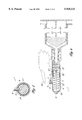
- FIG. 1 is an outside elevation of the exterior of the device attached to a syringe.
- FIG. 2 is a section elevation of the device attached to a syringe.
- FIG. 3 is a section view of the release means as taken trough FIG. 2.
- FIG. 4 is a section elevation of the device showing the slideable piston crushing the second end of the needle cannula.
- FIG. 5 is a section elevation of the device of the second perferred embodiments showing a composite needle cannula.
- FIG. 6 is a section elevation of the second preferred embodiment showing the second end of the composite needle cannula crushed.
- FIG. 7 is a section elevation of the device of the second preferred embodiment showing a glass composite cannula crushed.
- FIG. 1 there is shown an elevation view of the device 1 suitably fixed to a syringe 2.
- the first end of the needle cannula 3 is shown extending out of the first end of the elongated capsule 9.
- the first end of the hub 10 is shown suitably fixed to the second end of the elongated capsule 9.
- the second end of the hub 10 is shown suitably fixed to the first end of the threaded lock 11.
- the second end of the threaded lock 11 is near the plunger 14 of the syringe 2.
- the threaded lock 11 is shown suitably fixed to the internal threads 12 of the threaded extension 15 which is part of the syringe 2.
- the threaded extension 15 and the internal threads 12 are a standard connection for needles as they are manufactured and sold at the present time.
- the hub 10 and the threaded lock 11 would all be a standard size of the device that holds a conventional needle cannula.
- the threaded extension 15 the hub 10 and the threaded lock could also be a conventional slip on friction connector or an eccentric connection or a catheter type of connection by design choice.
- the hub 10 is shown with an inside and an outside that would attach to any desired syringe of any size.
- a latch means 4 is shown suitably fixed to the outside of the elongated capsule 9.
- the latch means 4 is comprised of two fulcrums 6 each with a first end that is suitably fixed to the outside surface of the elongated capsule 9.
- a first hole 16 is formed near the second end of each fulcrum 6 wherein a fulcrum pin 7 is inserted through each first hole 16 wherein the fulcrum pin 7 is fixed to each fulcrum 6.
- a latch bar 8 is shown with a first end and a second end and a second hole is formed in said latch bar 8 that extends from the first side to the second side of said latch bar 8 wherein said fulcrum pin 7 is disposed in said second hole thereby allowing said latch bar 8 to rotate about said fulcrum pin 7.
- a third hole 19 is formed at the first end of latch bar 8 wherein said third hole 19 extends from the first side to the second side of said latch bar 8.
- a piston stop 13 is shown suitably fixed to said latch bar 8 by a piston stop pin 21.
- the piston stop pin 21 extends from the first side of the latch bar 8, through a fourth hole formed in the piston stop 13 and to the second side of the latch bar 8.
- the piston stop 13 extends from the latch bar 8, through a hole formed in the elongated capsule 9 that extends from the outside to the inside of the elongated capsule 9.
- the piston stop 13 further extends into a piston 22 that is disposed within the elongated capsule 9.
- the piston stop 13, prevents the piston from moving or being moved until the piston stop 13 is removed from the piston 22.
- FIG. 2 there is shown is shown a section elevation of the device 1 attached to a syringe 2.
- the first end of the piston stop 13 is shown rotatably fixed to the first end of the latch bar 8 by the piston stop pin 21.
- the piston stop 13 is shown extending through the piston stop hole 23 that extends from the outside surface of the elongated capsule 9 to the inside surface of the elongated capsule 9 wherein the second end of the piston stop 13 is disposed in the piston hole 24 formed near the second end of the piston 22.
- the piston stop 13 prevents the piston 22 from moving or being moved longitudeinally within the elongated capsule 9.
- a biased spring 25 is shown compressed within the piston cavity 26.
- the piston cavity 26 has a first end near the first end of the elongated capsule 9 and the second end of the piston cavity 26 is fixed to the first end of the piston base 27.
- the piston cavity has an outside surface and an inside surface.
- the biased spring 25 is thrusting on the first end of the piston base 27 but is restrained by the piston stop 13.
- the needle cannula 3 is shown with a point 28 on the first end. The needle cannula 3 extends into the elongated capsule 9 through a needle cannula tunnel 18 that is formed in the first end of the elongated capsule.
- the needle cannula tunnel 18 provides latteral stability for the needle cannula 3 as the needle cannula is being injected into a body 29 or part of a body.
- the needle cannula tunnel will also prevent the needle cannula 3 from moving latteraly 46 as the needle cannula 3 is being withdrawn into the inside of the elongated capsule 9 or as the needle cannula 3 is being injected into a body 29.
- the first end of the biased spring 25 is shown thrusting on the first capsule flat 30 that is formed on the inside on the first end of the elongated capsule 9.
- the second end of the biased spring 25 is thrusting on the first side of the piston base 27.
- the second end of the biased spring 25 is shown contained in the cavity 26 formed in the piston 22.
- the cavity 26 is shown with an inside surface and an outside surface, a first end near the first capsule flat 30 and a second end at the piston base 27.
- the needle cannula 3 is shown extending through the piston 22 and through a base hole 43 formed in the piston base 27 that extends from the first end of the piston base 27 through the second end of the piston base 27 wherein the needle cannula 3 is suitably fixed to the piston base 27 that is at the second end of the piston 22.
- the needle cannula is shown with at least one needle cannula arc 31 that will enable the needle cannula 3 to colapse upon itself as will be shown in FIG. 4.
- the second end of the needle cannula 3 is shown suitably fixed to the first side of a flange 32 and wherein the second side of the flange 32 could be pressed against an internal part of the syringe 2 to provide a high pressure fluid tight connection between the needle cannula 3 and the syringe 2 or in any conventional method of providing a high pressure fluid tight connection between a needle cannula 3 and a syringe 2 by design choice.
- the fluid will travel from the syringe 2 into the needle cannula 3 past or through the flange 32 through the needle cannula arc 31 or arcs, through the first end of the needle cannula 3 and into a body 29.
- FIG. 3 there is shown a section elevation of the device 1 as taken through FIG. 2.
- the piston base 27 is shown with the piston stop 13 suitably disposed in the piston hole 24.
- the piston stop 13 is shown rotatably fixed to the latch bar 8.
- the inside surface and the outside surface of the elongated capsule 9 are shown.
- FIG. 4 there is shown a section elevation of the device 1 during or after the piston 22 has been released.
- a finger 33 has pressed downward on the second end of the latch bar 8 thereby rotating the latch bar 8 about the fulcrum pin 7 and further causing the latch bar 8 to pull the piston stop 13 out of the piston hole 23 formed in the piston base 27 of the piston 22 thereby releasing the piston 22 wherein the biased spring 25 is allowed to thrust the piston 22 and the piston base 27 toward the second end of the elongated capsule 9 thereby crushing the needle cannula arc section of the needle cannula 3 into the inside second end of the elongated capsule 9.
- the first end of the needle cannula 3 and the point 28 of the needle cannula 3 are withdrawn through the needle cannula tunnel 18 and into the inside of the elongated capsule 9 where the point 28 is completly sheltered and therefore cannot prick or othewise injure others by spreading bacteria or germs.
- the biased spring 25 will also keep a constant pressure on the piston 22 thereby preventing the point 28 of the needle cannula 3 from falling out of the inside of the elongated capsule 9.
- the needle cannula 3 is also completly destroyed.
- FIG. 5 there is shown a second device 36 of the second preferred embodiment with a composite needle cannula 35.
- the elongated capsule 9, the latch means 4, the piston 22, the biased spring 25, the hub 4 and the piston stop 13 are all the same as shown in FIG. 1, FIG. 2, FIG. 3 and FIG. 4; only the composite needle cannula 35 is different from the needle cannula of the first preferred embodiment.
- the first end of the composite needle cannula 35 is a hard needle cannula 37 made out of a suitable material such as steel or even hard plastic if it is possible to penetrate the skin of a body 38.
- the second end of the composite needle cannula 35 is made out of a flexable or bendable material such as plastic or bendable metal tubing that can contain medicament under high pressure but will be latteraly bendable.
- the bendable cannula 39 is shown suitably fixed to the hard needle cannula 37 near the joint flange 40.
- the connection of the hard needle cannula 37 and the bendable cannula 39 could be inside of the piston base 27 or at the first end of the piston base 27 by design choice.
- the bendable material could also be crushable material such as glass, a hard plastic or a brittle metal.
- FIG. 6 there is shown a section elevation of the second device 36 of the second preferred embodiment.
- a finger 33 or a thumb has depressed the latch bar 8 thereby pulling up on the piston stop 13, further releasing the piston 22 allowing the biased spring 25 to thrust the piston 22 into the inside second end of the elongated capsule 9 thereby compressing the bendable cannula 39 into a bendable cannula pile 41.
- the hard needle cannula 37 has been withdrawn past the needle cannula tunnel 18 into the inside of the elongated capsule wherein the hard needle cannula cannot prick a person or otherwise spread an infectious disease such as aids or hepatitis or other diseases.
- FIG. 7 there is shown a section elevation of the second device 36 of the second preferred embodiment wherein the second end of the composite needle cannula 35 is made out of glass or another suitable material wherein the crushable cannula 47 has been shattered into a brittle cannula pile 44.
- the hollow glass cannula 45 is shown broken into many pieces of glass particules that cannot be repaired or reused.
- the device has now been rendered useless and the hard needle cannula 37 has been withdrawn into the elongated capsule 9 wherein it cannot prick another person.
- the latching means could be anothers design or there could be two or more latch means
- the device could be a slip lock connection for the syringe.
Abstract
Description
Claims (7)
Priority Applications (1)
| Application Number | Priority Date | Filing Date | Title |
|---|---|---|---|
| US09/130,968 US5935113A (en) | 1998-08-07 | 1998-08-07 | Modular one handed safety retractable needle cannula |
Applications Claiming Priority (1)
| Application Number | Priority Date | Filing Date | Title |
|---|---|---|---|
| US09/130,968 US5935113A (en) | 1998-08-07 | 1998-08-07 | Modular one handed safety retractable needle cannula |
Publications (1)
| Publication Number | Publication Date |
|---|---|
| US5935113A true US5935113A (en) | 1999-08-10 |
Family
ID=22447256
Family Applications (1)
| Application Number | Title | Priority Date | Filing Date |
|---|---|---|---|
| US09/130,968 Expired - Fee Related US5935113A (en) | 1998-08-07 | 1998-08-07 | Modular one handed safety retractable needle cannula |
Country Status (1)
| Country | Link |
|---|---|
| US (1) | US5935113A (en) |
Cited By (16)
| Publication number | Priority date | Publication date | Assignee | Title |
|---|---|---|---|---|
| US6099500A (en) * | 1999-12-03 | 2000-08-08 | Dysarz; Edward D. | Safety needle cannula module that is activated by a safety syringe and plunger module |
| US20010056256A1 (en) * | 1999-05-21 | 2001-12-27 | Mallinckrodt Inc. | Suspension device and method |
| US6398743B1 (en) * | 2000-07-28 | 2002-06-04 | Mdc Investment Holdings, Inc. | Medical device for inserting a guide wire having a retractable needle |
| US6585701B1 (en) * | 1998-06-15 | 2003-07-01 | Edward D. Dysarz | Trap in modular hub chamber spring needle cannula |
| US6605067B1 (en) * | 1998-11-20 | 2003-08-12 | Novo Nordisk A/S | Injection needle |
| US6616637B2 (en) * | 2000-06-21 | 2003-09-09 | Gary E. Alexander | Fluid collection safety syringe |
| US6648856B1 (en) * | 1997-05-27 | 2003-11-18 | Jorge Luis Argento | Needle for medical and/or veterinary use that includes an extensible telescopic system that covers the needle avoiding its future use |
| US20040019327A1 (en) * | 2000-06-30 | 2004-01-29 | Anja Metzger | Method and an apparatus for a port access system |
| US6712787B1 (en) | 2000-05-19 | 2004-03-30 | Edward D. Dysarz | Self destructive safety syringe |
| US20050027256A1 (en) * | 2000-04-18 | 2005-02-03 | Barker John M. | Medical device with shield having a retractable needle |
| WO2006119556A1 (en) * | 2005-05-09 | 2006-11-16 | Analytica Limited | A retractable needle device |
| WO2006136364A1 (en) * | 2005-06-20 | 2006-12-28 | Novo Nordisk A/S | Cannula with ductile portion |
| US20080177235A1 (en) * | 2007-01-23 | 2008-07-24 | Becton, Dickinson And Company | Retracting safety pen needle |
| US20090105662A1 (en) * | 2007-10-23 | 2009-04-23 | Boston Scientific Scimed. Inc. | Apparatus and method for treating tissue |
| GB2532795A (en) * | 2014-11-28 | 2016-06-01 | Owen Mumford Ltd | Retractable needle assemblies |
| US11260173B2 (en) * | 2016-09-15 | 2022-03-01 | Becton, Dickinson And Company | Needle assembly for subcutaneous infusion set |
Citations (14)
| Publication number | Priority date | Publication date | Assignee | Title |
|---|---|---|---|---|
| US3008570A (en) * | 1960-03-30 | 1961-11-14 | Brunswick Corp | Ejector package |
| US3107785A (en) * | 1960-10-04 | 1963-10-22 | Brunswick Corp | Syringe-container structure |
| US3306291A (en) * | 1964-04-14 | 1967-02-28 | Burron Medical Prod Inc | Disposable sterile syringes, needle containers and the like having prestressed frangible portions therein |
| US3895633A (en) * | 1973-09-27 | 1975-07-22 | Survival Technology | Large capacity syringe |
| US4300678A (en) * | 1980-04-07 | 1981-11-17 | Becton, Dickinson And Company | Syringe package with evidence of opening |
| US4356822A (en) * | 1980-10-17 | 1982-11-02 | Winstead Hall Deborah | Syringe assembly |
| US4425120A (en) * | 1982-04-15 | 1984-01-10 | Sampson Norma A | Shielded hypodermic syringe |
| US4466435A (en) * | 1981-09-04 | 1984-08-21 | Murray William M | Bone cement nozzle and method |
| US4655751A (en) * | 1986-02-14 | 1987-04-07 | Harbaugh John T | Liquid dispensing and receiving syringe |
| US4664654A (en) * | 1986-03-07 | 1987-05-12 | Strauss Eric C | Automatic protracting and locking hypodermic needle guard |
| US4702738A (en) * | 1986-05-22 | 1987-10-27 | Spencer Treesa A | Disposable hypodermic syringe and needle combination having retractable, accident preventing sheath |
| US4894055A (en) * | 1988-12-28 | 1990-01-16 | Sudnak Paul J | Needle guard assembly for use with hypodermic syringes and the like |
| US4946446A (en) * | 1989-06-14 | 1990-08-07 | Vadher Dinesh L | Retractable needle |
| US5246428A (en) * | 1992-07-30 | 1993-09-21 | Falknor Donald W | Needle safety mechanism |
-
1998
- 1998-08-07 US US09/130,968 patent/US5935113A/en not_active Expired - Fee Related
Patent Citations (14)
| Publication number | Priority date | Publication date | Assignee | Title |
|---|---|---|---|---|
| US3008570A (en) * | 1960-03-30 | 1961-11-14 | Brunswick Corp | Ejector package |
| US3107785A (en) * | 1960-10-04 | 1963-10-22 | Brunswick Corp | Syringe-container structure |
| US3306291A (en) * | 1964-04-14 | 1967-02-28 | Burron Medical Prod Inc | Disposable sterile syringes, needle containers and the like having prestressed frangible portions therein |
| US3895633A (en) * | 1973-09-27 | 1975-07-22 | Survival Technology | Large capacity syringe |
| US4300678A (en) * | 1980-04-07 | 1981-11-17 | Becton, Dickinson And Company | Syringe package with evidence of opening |
| US4356822A (en) * | 1980-10-17 | 1982-11-02 | Winstead Hall Deborah | Syringe assembly |
| US4466435A (en) * | 1981-09-04 | 1984-08-21 | Murray William M | Bone cement nozzle and method |
| US4425120A (en) * | 1982-04-15 | 1984-01-10 | Sampson Norma A | Shielded hypodermic syringe |
| US4655751A (en) * | 1986-02-14 | 1987-04-07 | Harbaugh John T | Liquid dispensing and receiving syringe |
| US4664654A (en) * | 1986-03-07 | 1987-05-12 | Strauss Eric C | Automatic protracting and locking hypodermic needle guard |
| US4702738A (en) * | 1986-05-22 | 1987-10-27 | Spencer Treesa A | Disposable hypodermic syringe and needle combination having retractable, accident preventing sheath |
| US4894055A (en) * | 1988-12-28 | 1990-01-16 | Sudnak Paul J | Needle guard assembly for use with hypodermic syringes and the like |
| US4946446A (en) * | 1989-06-14 | 1990-08-07 | Vadher Dinesh L | Retractable needle |
| US5246428A (en) * | 1992-07-30 | 1993-09-21 | Falknor Donald W | Needle safety mechanism |
Cited By (28)
| Publication number | Priority date | Publication date | Assignee | Title |
|---|---|---|---|---|
| US6648856B1 (en) * | 1997-05-27 | 2003-11-18 | Jorge Luis Argento | Needle for medical and/or veterinary use that includes an extensible telescopic system that covers the needle avoiding its future use |
| US6585701B1 (en) * | 1998-06-15 | 2003-07-01 | Edward D. Dysarz | Trap in modular hub chamber spring needle cannula |
| US6605067B1 (en) * | 1998-11-20 | 2003-08-12 | Novo Nordisk A/S | Injection needle |
| US20010056256A1 (en) * | 1999-05-21 | 2001-12-27 | Mallinckrodt Inc. | Suspension device and method |
| US6770051B2 (en) * | 1999-05-21 | 2004-08-03 | Mallinckrodt Inc. | Suspension device and method |
| US20040260242A1 (en) * | 1999-05-21 | 2004-12-23 | Mallinckrodt Inc. | Suspension device and method |
| US6099500A (en) * | 1999-12-03 | 2000-08-08 | Dysarz; Edward D. | Safety needle cannula module that is activated by a safety syringe and plunger module |
| US20050027256A1 (en) * | 2000-04-18 | 2005-02-03 | Barker John M. | Medical device with shield having a retractable needle |
| US7153276B2 (en) | 2000-04-18 | 2006-12-26 | Mdc Investment Holdings, Inc. | Medical device with shield having a retractable needle |
| US6712787B1 (en) | 2000-05-19 | 2004-03-30 | Edward D. Dysarz | Self destructive safety syringe |
| US6616637B2 (en) * | 2000-06-21 | 2003-09-09 | Gary E. Alexander | Fluid collection safety syringe |
| US20040019327A1 (en) * | 2000-06-30 | 2004-01-29 | Anja Metzger | Method and an apparatus for a port access system |
| US6398743B1 (en) * | 2000-07-28 | 2002-06-04 | Mdc Investment Holdings, Inc. | Medical device for inserting a guide wire having a retractable needle |
| WO2006119556A1 (en) * | 2005-05-09 | 2006-11-16 | Analytica Limited | A retractable needle device |
| WO2006136364A1 (en) * | 2005-06-20 | 2006-12-28 | Novo Nordisk A/S | Cannula with ductile portion |
| CN101203257B (en) * | 2005-06-20 | 2011-04-20 | 诺沃-诺迪斯克有限公司 | Cannula with ductile portion |
| JP2008543460A (en) * | 2005-06-20 | 2008-12-04 | ノボ・ノルデイスク・エー/エス | Cannula with ductile part |
| US20080177235A1 (en) * | 2007-01-23 | 2008-07-24 | Becton, Dickinson And Company | Retracting safety pen needle |
| US7540858B2 (en) * | 2007-01-23 | 2009-06-02 | Becton, Dickinson And Company | Retracting safety pen needle |
| US8679112B2 (en) | 2007-10-23 | 2014-03-25 | Boston Scientific Scimed, Inc. | Apparatus and method for treating tissue |
| US8262626B2 (en) * | 2007-10-23 | 2012-09-11 | Boston Scientific Scimed, Inc. | Apparatus and method for treating tissue |
| US20090105662A1 (en) * | 2007-10-23 | 2009-04-23 | Boston Scientific Scimed. Inc. | Apparatus and method for treating tissue |
| US9867943B2 (en) | 2007-10-23 | 2018-01-16 | Boston Scientific Scimed, Inc. | Apparatus and method for treating tissue |
| GB2532795A (en) * | 2014-11-28 | 2016-06-01 | Owen Mumford Ltd | Retractable needle assemblies |
| WO2016083834A1 (en) * | 2014-11-28 | 2016-06-02 | Owen Mumford Limited | Retractable needle assemblies |
| CN107106787A (en) * | 2014-11-28 | 2017-08-29 | 欧文蒙福德有限公司 | Retractable needles component |
| US10532164B2 (en) | 2014-11-28 | 2020-01-14 | Owen Mumford Limited | Retractable needle assemblies |
| US11260173B2 (en) * | 2016-09-15 | 2022-03-01 | Becton, Dickinson And Company | Needle assembly for subcutaneous infusion set |
Similar Documents
| Publication | Publication Date | Title |
|---|---|---|
| US5180369A (en) | Self destructive safety syringe | |
| US4978343A (en) | Trap in barrel one handed retractable safety syringe | |
| US5935113A (en) | Modular one handed safety retractable needle cannula | |
| US5129884A (en) | Trap in barrel one handed retracted intervenous catheter device | |
| US4973316A (en) | One handed retractable safety syringe | |
| US5125414A (en) | Trap in barrel one handed retracted blood sampling device | |
| US4955868A (en) | Disposable safety medical syringe | |
| US5112307A (en) | Dental syringe having a medication filled carpule and an automatically-detaching piston stem | |
| US8945049B2 (en) | Auto-injector with active agent container latching | |
| US5997507A (en) | Biased spring hard needle retractable IV catheter | |
| US10369277B2 (en) | Invisible needle | |
| JP2788932B2 (en) | Hypodermic syringes and needle cannula and cannula lock combinations for hypodermic syringes | |
| US4921486A (en) | Disposable syringe with retracting needle | |
| US5836917A (en) | Self retracting medical needle apparatus and methods | |
| US5368568A (en) | Disabling hypodermic syringe | |
| US6746420B1 (en) | Parenteral apparatus | |
| US6102894A (en) | Modular retractable spring needle cannula blood collection device | |
| US6235003B1 (en) | Inclined plane latching device for a spring needle cannula and a spring needle | |
| US4995869A (en) | Mono-use syringe for hypodermic injections | |
| EP0451314A1 (en) | Dental syringe having a medication filled carpule and a retractable needle cannula | |
| US6186979B1 (en) | One-handed retractable blood collection device with trap-in container | |
| EP0893136A3 (en) | Intravenous cannula | |
| JPH025969A (en) | Injector | |
| US5891093A (en) | Trap in hub chamber safety needle cannula syringe tip | |
| DE69008850T2 (en) | SYRINGE WITH INTERCHANGEABLE AND RETRACTABLE CANNULA PLATFORM. |
Legal Events
| Date | Code | Title | Description |
|---|---|---|---|
| REMI | Maintenance fee reminder mailed | ||
| REIN | Reinstatement after maintenance fee payment confirmed | ||
| FP | Lapsed due to failure to pay maintenance fee |
Effective date: 20030810 |
|
| FEPP | Fee payment procedure |
Free format text: PETITION RELATED TO MAINTENANCE FEES FILED (ORIGINAL EVENT CODE: PMFP); ENTITY STATUS OF PATENT OWNER: SMALL ENTITY |
|
| FEPP | Fee payment procedure |
Free format text: PETITION RELATED TO MAINTENANCE FEES FILED (ORIGINAL EVENT CODE: PMFP); ENTITY STATUS OF PATENT OWNER: SMALL ENTITY |
|
| FEPP | Fee payment procedure |
Free format text: PETITION RELATED TO MAINTENANCE FEES FILED (ORIGINAL EVENT CODE: PMFP); ENTITY STATUS OF PATENT OWNER: SMALL ENTITY |
|
| FEPP | Fee payment procedure |
Free format text: PETITION RELATED TO MAINTENANCE FEES GRANTED (ORIGINAL EVENT CODE: PMFG); ENTITY STATUS OF PATENT OWNER: SMALL ENTITY |
|
| FEPP | Fee payment procedure |
Free format text: PAYER NUMBER DE-ASSIGNED (ORIGINAL EVENT CODE: RMPN); ENTITY STATUS OF PATENT OWNER: SMALL ENTITY Free format text: PAYOR NUMBER ASSIGNED (ORIGINAL EVENT CODE: ASPN); ENTITY STATUS OF PATENT OWNER: SMALL ENTITY |
|
| PRDP | Patent reinstated due to the acceptance of a late maintenance fee |
Effective date: 20040715 |
|
| FPAY | Fee payment |
Year of fee payment: 4 |
|
| REMI | Maintenance fee reminder mailed | ||
| FPAY | Fee payment |
Year of fee payment: 8 |
|
| SULP | Surcharge for late payment |
Year of fee payment: 7 |
|
| REMI | Maintenance fee reminder mailed | ||
| LAPS | Lapse for failure to pay maintenance fees | ||
| STCH | Information on status: patent discontinuation |
Free format text: PATENT EXPIRED DUE TO NONPAYMENT OF MAINTENANCE FEES UNDER 37 CFR 1.362 |
|
| FP | Lapsed due to failure to pay maintenance fee |
Effective date: 20110810 |