US5819840A - Thermostat with occupancy detector - Google Patents
Thermostat with occupancy detector Download PDFInfo
- Publication number
- US5819840A US5819840A US08/766,293 US76629396A US5819840A US 5819840 A US5819840 A US 5819840A US 76629396 A US76629396 A US 76629396A US 5819840 A US5819840 A US 5819840A
- Authority
- US
- United States
- Prior art keywords
- temperature
- switch
- area
- heating
- cooling
- Prior art date
- Legal status (The legal status is an assumption and is not a legal conclusion. Google has not performed a legal analysis and makes no representation as to the accuracy of the status listed.)
- Expired - Fee Related
Links
Images


Classifications
-
- G—PHYSICS
- G05—CONTROLLING; REGULATING
- G05D—SYSTEMS FOR CONTROLLING OR REGULATING NON-ELECTRIC VARIABLES
- G05D23/00—Control of temperature
- G05D23/19—Control of temperature characterised by the use of electric means
- G05D23/1902—Control of temperature characterised by the use of electric means characterised by the use of a variable reference value
-
- F—MECHANICAL ENGINEERING; LIGHTING; HEATING; WEAPONS; BLASTING
- F24—HEATING; RANGES; VENTILATING
- F24F—AIR-CONDITIONING; AIR-HUMIDIFICATION; VENTILATION; USE OF AIR CURRENTS FOR SCREENING
- F24F11/00—Control or safety arrangements
- F24F11/30—Control or safety arrangements for purposes related to the operation of the system, e.g. for safety or monitoring
- F24F11/46—Improving electric energy efficiency or saving
-
- F—MECHANICAL ENGINEERING; LIGHTING; HEATING; WEAPONS; BLASTING
- F24—HEATING; RANGES; VENTILATING
- F24F—AIR-CONDITIONING; AIR-HUMIDIFICATION; VENTILATION; USE OF AIR CURRENTS FOR SCREENING
- F24F11/00—Control or safety arrangements
- F24F11/62—Control or safety arrangements characterised by the type of control or by internal processing, e.g. using fuzzy logic, adaptive control or estimation of values
- F24F11/63—Electronic processing
- F24F11/64—Electronic processing using pre-stored data
-
- F—MECHANICAL ENGINEERING; LIGHTING; HEATING; WEAPONS; BLASTING
- F24—HEATING; RANGES; VENTILATING
- F24F—AIR-CONDITIONING; AIR-HUMIDIFICATION; VENTILATION; USE OF AIR CURRENTS FOR SCREENING
- F24F11/00—Control or safety arrangements
- F24F11/62—Control or safety arrangements characterised by the type of control or by internal processing, e.g. using fuzzy logic, adaptive control or estimation of values
- F24F11/63—Electronic processing
- F24F11/65—Electronic processing for selecting an operating mode
- F24F11/66—Sleep mode
-
- F—MECHANICAL ENGINEERING; LIGHTING; HEATING; WEAPONS; BLASTING
- F24—HEATING; RANGES; VENTILATING
- F24F—AIR-CONDITIONING; AIR-HUMIDIFICATION; VENTILATION; USE OF AIR CURRENTS FOR SCREENING
- F24F11/00—Control or safety arrangements
- F24F11/62—Control or safety arrangements characterised by the type of control or by internal processing, e.g. using fuzzy logic, adaptive control or estimation of values
- F24F11/63—Electronic processing
- F24F11/65—Electronic processing for selecting an operating mode
- F24F11/67—Switching between heating and cooling modes
-
- F—MECHANICAL ENGINEERING; LIGHTING; HEATING; WEAPONS; BLASTING
- F24—HEATING; RANGES; VENTILATING
- F24F—AIR-CONDITIONING; AIR-HUMIDIFICATION; VENTILATION; USE OF AIR CURRENTS FOR SCREENING
- F24F11/00—Control or safety arrangements
- F24F11/30—Control or safety arrangements for purposes related to the operation of the system, e.g. for safety or monitoring
-
- F—MECHANICAL ENGINEERING; LIGHTING; HEATING; WEAPONS; BLASTING
- F24—HEATING; RANGES; VENTILATING
- F24F—AIR-CONDITIONING; AIR-HUMIDIFICATION; VENTILATION; USE OF AIR CURRENTS FOR SCREENING
- F24F2120/00—Control inputs relating to users or occupants
- F24F2120/10—Occupancy
Definitions
- This invention relates to thermostat control systems and, more specifically, to a thermostat control system that controls the temperature settings in a room based on the occupancy of the room.
- thermostats When an unoccupied hotel room, office or dwelling is cooled or heated to personal comfort levels, energy and money are being wasted.
- Conventional thermostats generally have a set of manual controls, requiring the occupant of the room or dwelling to manually adjust the settings to their needs. If the occupant also happens to be the owner of the premises, chances are that they will make a conscious effort to lower the settings when they leave the premises, as they are acutely aware of the needless costs of running a heating and cooling system when their premises are unoccupied.
- the occupant of the room, office or dwelling is not the owner and does not have to pay for the cost of heating and cooling, chances are that they may not be quiet as conscientious. In fact, it is fairly safe to say that most non-owner occupants will make minimal or no effort to adjust the thermostat settings when they leave the room or premises unless they are personally responsible for the cost of heating or cooling the room, office, or premises.
- a dual set-point thermostatic controller assembly for controlling gas, oil, or electric heaters with air conditioning is provided.
- the assembly operates as a conventional household thermostat, sensing the environment's temperature and activating a switch selected heating or cooling unit.
- the thermostatic controller assembly disclosed herein is designed to automatically select one of two reference temperature sets. One reference temperature set is selected when the physical area to be environmentally controlled is occupied. The second reference temperature set is selected when the controlled area is unoccupied.
- the dual set-point thermostatic controller assembly comprises a thermostat control unit and an occupancy sensing unit.
- the control unit comprises a micro-controller for controlling and actuating a heating and cooling unit, a set of display devices for displaying the temperature of the room and desired reference temperature, a segment driver that connects the micro-controller to the display devices and drives the display devices in response to the micro-controller, and a memory device, which is programmed to store an occupied reference temperature, an unoccupied reference temperature, and a time delay.
- the micro-controller receives input from several internal and external sources: temperature sensors, occupancy sensors, a fan switch, a power switch, a system switch, a key switch, a programming switch, and the memory device.
- the micro-controller operates to select one of the two reference temperature sets by monitoring the occupancy sensor.
- the occupied reference temperatures typically chosen by the occupant of the room, is selected by the micro-controller when the physical area to be environmentally controlled is occupied.
- the unoccupied reference temperatures typically selected by the owner of the premises, is selected when the controlled area is unoccupied.
- the micro-controller monitors the temperature sensor, the occupancy sensor, and mechanical switches and determines which reference temperature applies and controls the heating and cooling unit accordingly.
- the fan switch has one of two positions: an ON position and an AUTO position. In the ON position the fan runs continuously. In the AUTO position, the micro-controller turns on the fan and heating or cooling unit when the environment temperature drops below (in the case of heating) or above (in the case of cooling) the reference temperature setting.
- the system switch is a three position switch monitored by the micro-controller to determine if the occupant has selected the heating operation, the cooling operation, or has turned the thermostat unit off. If the occupant has selected the COOL switch position, the micro-controller turns on or off the power control switch to control the cooling operation for the controlled environment. Similarly, if the occupant has selected the HEAT switch position, the micro-controller turns on or off the power control switch to control the heating operation to the controlled environment. If the occupant has selected the OFF switch position, the controller does not turn on the heating or cooling unit but continues to monitor and display the current temperature. The controller provides power to the fan, however, if the fan switch is placed in the ON position.
- the micro-controller determines the heating and cooling operational cycles by comparing the current environmental temperature measurement from the monitored temperature sensor to the applicable reference temperature, in the case of an occupied room to the reference temperature selected by the occupant or in the case of an unoccupied room to the default settings selected by the owner.
- the key switch has two positions: a counter-clockwise position, the normal operating position for the switch, and a clockwise position.
- the occupied reference temperature settings may be adjusted using the programming switch, as will be described below.
- a key is needed to move the switch from the counter-clockwise position to the clockwise position, where the unoccupied reference temperatures and a time delay can be programmed into the memory device.
- the reference temperatures for unoccupied operation can only be programmed when the key is inserted into the key switch and the key switch is in the clockwise position.
- the programming switch is a three position switch: a neutral center position, an INC (increase) position, and a DEC (decrease) position.
- a neutral center position To set the unoccupied reference temperature, the system switch is moved to indicate whether the cooling or heating temperature is being adjusted and then the programming switch is held in either the INC or DEC position to either increase or decrease the temperature.
- the key switch To set the unoccupied reference temperature, the key switch is rotated by the key to the clockwise position and then the system switch is moved to indicate whether the cooling or heating temperature is being adjusted.
- the programming switch is held in either the INC or DEC position to either increase or decrease the temperature.
- To set a time delay To set a time delay, the system switch is moved to the OFF position and the programming switch is moved to either the INC or DEC position to increase or decrease the time delay.
- the display devices are four digit liquid-crystal displays.
- the left two digits of the display device indicate the set point temperature currently referenced by the micro-controller.
- the right two liquid-crystal display digits indicate the current temperature of the environment area controlled by the dual set point thermostatic controller assembly.
- the left two digits of the liquid-crystal display device indicates the unoccupied reference temperature as it is increased or decreased and the right two digits of the display device will show two dashes (- -) confirming that the unoccupied reference temperature is addressed rather than the occupied reference temperature.
- the occupancy sensing unit includes an infrared sensor, which detects the heat emanating from a person's body. During periods of vacancy, the occupancy sensor will not send a trigger signal to the micro-controller. Without the triggering signal the micro-controller maintains the environmental conditions of the controlled area by use of the programmed set point reference temperatures intended for unoccupied conditions. During periods of occupancy, the micro-controller receives triggering signals from the occupancy sensor and maintains the environmental conditions of the controlled area by use of the programmed set point reference temperatures intended for occupied conditions.
- remote sensing units are provided.
- the remote sensing units communicate with the thermostat control unit using conventional telephone wires.
- Conventional telephone jacks are mounted to the remote sensing unit and to the control unit so that the remote sensing unit can transmit the triggering signal to the micro-controller.
- FIG. 1 is a perspective view of the dual set point thermostatic controller assembly of the present invention
- FIG. 2 is an exploded perspective view of the thermostatic controller unit of the present invention
- FIG. 3 is a cross-sectional view taken along line 3--3 of FIG. 2;
- FIG. 4 is a cross-sectional view taken along line 4--4 of FIG. 2;
- FIG. 5 is a cross-sectional view taken along line 5--5 of FIG. 2;
- FIG. 6 is an exploded perspective view of the sensing unit
- FIG. 7 is a cross-sectional view taken along line 7--7 of FIG. 6;
- FIG. 8 is a cross-sectional view taken along line 8--8 of FIG. 6;
- FIG. 9 is a cross-sectional view taken along line 9--9 of FIG. 6;
- FIG. 10a is a plan view of the control unit circuit board
- FIG. 10b is a plan view of the sensing unit circuit board
- FIG. 11 is a block diagram of the dual set point thermostatic controller assembly
- FIG. 12 is an electrical schematic of the occupancy sensing unit
- FIG. 13 is an electrical schematic of the micro-controller, segment driver and liquid-crystal display portion of the controller unit
- FIG. 14 is a flow diagram of the power on sequence of the computer program
- FIG. 15 is a flow diagram of the initialization sequence of the computer program
- FIG. 16 is a flow diagram of the interrupts sequence of the computer program
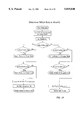
- FIG. 17 is a flow diagram of the control sequence of the computer program
- FIG. 18 is a flow diagram of the process keys sequence of the computer program
- FIG. 19 is a flow diagram of the determination of which data to modify sequence of the computer program.
- FIG. 20 is a flow diagram of the compressor timer sequence of the computer program.
- the dual set-point thermostatic controller assembly generally designated by the numeral 10 comprises a thermostat control unit 11 and an occupancy sensing unit 12.
- thermostat control unit 11 is mounted adjacent the sensor unit 12 on a mounting surface 13 in a room.
- control unit 11 comprises a micro-controller chip 14 and power supply 14a that are mounted on a circuit board 15 for actuating relay switches (not shown), which in turn actuate a heating and cooling system (not shown) and a set of display devices 16a and 16b.
- the display devices display the temperature of the room and desired reference temperature and are connected to the micro-controller through a segment display driver 18.
- Micro-controller 14 receives power from power supply 14a through a power regulator circuit 17 and input from several internal and external sources: a temperature sensor 19, the occupancy sensor 12, a memory device 20, and a plurality of mechanical switches.
- Regulator circuit 17 maintains the level of the voltage supply to the micro-controller chip 14 at approximately 3-volts. Regulator circuit 17 is powered by the three 1.5-volt batteries and a standard 60 HZ power supply (not shown). Regulator circuit 17 includes a 60 HZ feed circuit 17a that connects to the 60 Hz supply through system switch 27. System switch 27 and fan switch 26 are both powered by the 60 Hz power supply. By including feed circuit 17a, the micro-controller 14 generally does not draw power from the batteries. As a result, the batteries have a longer life and are only drained when there is a general power failure in the dwelling's main electrical supply.
- Temperature sensor 19 provides information about the environment to be controlled and comprises temperature circuit 19a with a thermistor 19b.
- Thermistors are temperature-sensitive bilateral resistors that exhibit a negative temperature coefficient. In other words, the device exhibits a high resistance at low temperatures and a low resistance at high temperatures. Depending on the temperature of the environment, the thermistor's resistance values will vary and cause the temperature circuit 19a to generate a high or low input to the micro-controller chip 14.
- Occupancy sensor unit 12 provides information about the occupancy of the room and includes an infrared sensor 22, a dual operational-amplifier circuit 23, and a dual-comparator circuit 24, all of which are mounted on a circuit board 25.
- infrared sensor 22 comprises a pyrosensor transistor which sends a triggering signal when heat is detected to the micro-controller chip 14, causing the controller chip 14 to use the occupied reference temperatures.
- the transistor does not send a triggering signal to the micro-controller 14.
- the micro-controller chip 14 uses the default reference temperatures--the unoccupied reference temperatures set by the owner.
- Memory device 20 stores information about the desired reference temperatures for an occupied room and unoccupied room and provides the information to the micro-controller chip 14.
- an unoccupied-heating reference temperature there are four reference temperatures: an unoccupied-heating reference temperature, an unoccupied-cooling reference temperature, an occupied-heating reference temperature, and an occupied-cooling reference temperature. Default values are generally provided for all four reference temperatures and stored on the memory device at the manufacturers. As shown in FIG. 13, an EEPROM memory device is used; however, any industry standard memory device can be substituted, as would be understood by a person having ordinary skill in the art.
- Micro-controller chip 14 operates to select one of the four reference temperatures stored in the memory device 20 by monitoring the occupancy sensor 22, a fan switch 26, and a system switch 27.
- Fan switch 26 has one of two positions: an ON and an AUTO position. In the ON position the fan (not shown) runs continuously. In the AUTO position, the micro-controller 14 turns on the fan and heating or cooling unit when the environment temperature drops below (in the case of heating) the heating reference temperature setting or above (in the case of cooling) the cooling reference temperature setting.
- System switch 27 is a three-position switch, with a COOL position, a HEAT position, and an OFF position. If the occupant has selected the COOL switch position, micro-controller 14 will compare the cooling reference temperature to the temperature detected by the thermal sensor 19. If the temperature detected by the thermal sensor 19 is higher than the cooling reference temperature, the micro-controller will actuate the cooling unit by turning on a power switch 28, the position of the system switch directs the current from the power switch to the appropriate heating or cooling unit through lead wire 27a, shown in FIG. 2.
- Power switch 28 comprises a power switching circuit 28a and a triac 28b which connect to the 60 Hz power supply. Triacs are bidirectional thrysistors that switch from a blocking state to a conducting state for an applied voltage.
- micro-controller 14 will compare the heating reference temperature to the temperature detected by the thermal sensor 19. If the temperature detected by the thermal sensor 19 is lower than the heating reference temperature, the micro-controller 14 will actuate the heating unit by turning on the power switch which in turn sends current through lead wire 27b, as shown in FIG. 2, to the relay switch (not shown) for the heating unit. As described above, the micro-controller chip 14 chooses between the occupied reference temperatures and the unoccupied reference temperatures based on the presence of the triggering signal generated by occupancy sensing unit 12.
- the controller 14 will not turn on the heating or cooling unit but will continue to monitor and display the current temperature on the display devices 16a and 16b.
- the controller 14 will, however, provide power to the fan through the power switch 28 and lead wire 27c, as shown in FIG. 2, which in turn sends power to the fan relay fan relay switch (not shown), if switch 26 is placed in the ON position.
- a key switch 29 is provided which has two positions: a counter-clockwise position and a clockwise position. In the counter-clockwise position, the occupied reference temperature settings may be adjusted. In the clockwise position, the unoccupied reference temperature settings may be adjusted. However, a key (not shown) is needed to move key switch 29 from the counter-clockwise position, which is the normal operating position for the switch, to the clock-wise position, where the unoccupied reference temperatures and a time delay can be programmed into the memory device 20. The reference temperatures for unoccupied operation can only be programmed when the key switch 29 is in the clockwise position.
- a programming switch 30 is provided.
- Programming switch 30 is a three position switch that is spring-loaded to normally remain in a neutral center position. The other two positions are an INC position and a DEC position. In the INC position, programming switch 30 increments the reference temperature at a rate of one count per second. Similarly, when programming switch 30 is held in the DEC position, the switch decrements the reference temperature at a rate of one count per second. As there are four reference temperatures, the micro-controller monitors the position of key switch 29 and the position of the system switch 27 to determine which of the four reference temperatures is to be adjusted.
- key switch 29 is rotated by the key to the clockwise position and system switch 27 is moved to the OFF position.
- a default time delay can be pre-programmed into the memory at the manufacturing facilities.
- programming switch 30 is moved to either the INC or DEC position. The left two digits of the display device will display the factory set time delay or the previously programmed time delay for three seconds and then will increase or decrease the time until the programming switch is returned to its center position.
- the display devices 16a and 16b are four digit liquid-crystal displays.
- the left two digits of the display device 16a indicate the reference set point temperature currently referenced by the micro-controller.
- the right two liquid-crystal display digits 16b indicate the current temperature of the environment area controlled by the dual set-point thermostatic controller assembly.
- the micro-controller chip 14 is programmed to drive (through the segment driver 18) the left two digits of the liquid-crystal display device 16a to display the programmed temperature and the right two digits of liquid-crystal display device 16b to display two dashed (- -).
- the micro-controller chip 14 is programmed drive the left two digits to display the factory set time delay or the previously programmed time delay for three seconds and then to increase or decrease the time until the programming switch is returned to its center position. During this sequence the right two digits will display four vertical lines (
- a battery monitor circuit 31 is provided. Referring to FIG. 13, battery monitor circuit 31 is a simple circuit having a pair of MOSFETs which connect to the battery and are driven by the battery when the battery is charged, thus allowing current to pass through the circuit and back to the micro-controller chip 14.
- the MOSFETS do not send a current to the controller chip and in response, the micro-controller chip drives reacts to this by driving the left two digits to indicate a LOW BATTERY signal (Lb).
- Lb LOW BATTERY signal
- this operation occurs approximately 60 days prior to the battery terminal voltage actually falling to a level requiring a system shutdown condition. If the assembly's battery terminal voltage is allowed to fall to a shutdown level the battery monitor circuit will trigger the system to discontinue operations.
- housing 32 In order to protect the micro-controller chip 14 and circuit board 15 from the environment, the circuit board 15 is mounted in a housing 32. As best shown in FIG. 2, housing 32 includes a top cover portion 33 and a base 34. Top cover portion 33 is generally rectangular in shape and sized to fit over base 34. Circuit board 15 is mounted to the underside of top cover portion 33 by fasteners 33a which anchor into downwardly projecting bosses 33b. In order to view display devices 16a and 16b and to access key switch 29, cover portion 33 includes apertures 33d and 33e. Apertures 33d are sized to allow an unobstructed view of all four digits of the liquid-crystal display device 16a and 16b. Key switch 29 is mounted in aperture 33e.
- cover portion 33 further includes a downwardly extending lip portion 33c that slides over the base 34 and a set of downwardly extending tabs 33f which extend from the inner wall of lip portion 33c.
- the base 34 includes a mounting flange 34a for mounting the unit to mounting surface 13 and an upstanding lip portion 34b.
- Inner wall 34c of upstanding lip portion 34b includes a set of recesses 33d which provide a slot into which downwardly projecting tabs 33f of top cover portion 33 snap, thus releasably securing top cover portion 33 to base 34.
- base 34 includes a battery housing 35 and battery contacts 35b for supporting and holding three AAA-batteries 35a, which power the control unit 11, and a set of terminal blocks 36 for connecting the control unit 11 to the external inputs and outputs.
- battery housing 35 can be modified to support other standard batteries provided that the total voltage supply is approximately 4.5 volts.
- Sensing unit 12 similarly includes a generally rectangular shaped housing 40. As best shown in FIG. 6, housing 40 comprises a base 41 and a cover 42.
- Base 41 generally includes a mounting flange 41a, for mounting sensor unit 12 to mounting surface 13, and an upstanding lip portion 41b, which provides a compartment 41c for storing a battery 46 and battery leads 46a.
- Cover 42 includes a downwardly depending lip portion 42a, which slides over upwardly extending lip portion 41b of base 41, and a set of downwardly extending bosses 42b.
- Sensing unit circuit board 25 is mounted to the underside of cover 42 by a set of fasteners 42c which extend into bosses 42b.
- Cover 42 is removably secured to base 41 by tabs 42 which extend downwardly from the inner wall of lip portion 42a and engage recesses 41d provided on the inner wall of upwardly depending lip portion 41b of base 41, thus forming a snap-fit connection between the cover portion 42 and base 41.
- tabs 42 which extend downwardly from the inner wall of lip portion 42a and engage recesses 41d provided on the inner wall of upwardly depending lip portion 41b of base 41, thus forming a snap-fit connection between the cover portion 42 and base 41.
- the top cover portion and base of both housing units can be connected using other conventional methods, as understood by a person having ordinary skill in the art
- an window opening 43 is provided in the in the top cover.
- a curved fresnel lens 45 is positioned in the window opening and supported by a set of raised rails 43a, which project outwardly from the top surface of the cover 42.
- Opening 43 is positioned to align fresnel lens 45 directly above the infrared sensor 22, as lens 45 operates like a wide angled lens for the infrared sensor 22 and directs and focuses the infrared waves onto the transistor 19a of the occupancy sensor 22.
- the lens 45 preferably has a horizontal viewing angle of approximately one hundred degrees.
- the lens vertical viewing angle is significantly smaller and extends from a horizontal plane defined by a lower edge of the lens 45 to a few degrees above the horizontal plane.
- the vertical viewing angle is limited so that the sensor 22 will generally not detect pets that are roaming around on the floor.
- the sensor unit 12 detects human body heat within a nominal range of twelve to fifteen feet and is mounted approximately three feet above the floor level so human occupants that are lying down on a bed or sofa will still be detected.
- Control unit 11 and occupancy sensor unit 12 connect together by conventional telephone lines (not shown) which connect to the circuit boards 15 and 25 by conventional telephone jacks 49.
- conventional telephone lines not shown
- the jacks and telephone line connections permit several sensing units to be connected to the control unit.
- the separation between the control unit 11 and sensor 12 is, therefore, limited only by the length of telephone line that is on hand.
- an remote sensing unit 50 can be added to thermostatic controller assembly 10. Since there are two jacks 49 mounted on the control unit circuit board 15 and two jacks 49 mounted on the adjacent sensor unit 12, the remote sensing unit 50 can either be connected through a telephone line to the adjacent sensor unit 12 and, therefore, connected in series with the adjacent sensor unit 12 or connected directly to the control unit 11 and, therefore, be connected in parallel with the adjacent sensor unit. If more than one remote sensing unit 50 is needed, the second sensing unit can be serially connected to the first remote sensing unit or connected in parallel to the first remote sensing unit by connecting in series to the adjacent mounted sensor unit. As it can be understood by one having ordinary skill in the art, many other combinations are possible. ##SPC1##
Abstract
An energy saving controller for an air conditioning system comprising a temperature sensor or sensing and measuring the temperature in an area to be controlled, a memory device for storing a first set and a second set of reference temperatures, each set of reference temperatures including a heating reference temperature and a cooling reference temperature, and a controller in communication with the memory device for selecting one of the first and second sets of reference temperatures in the memory and for comparing the selected set of reference temperatures to the measured temperature of the area. The controller is adapted to select one set of reference temperatures when the area is unoccupied by a person and to select the other set of reference temperatures when the area is occupied by a person. The occupancy information is provided to the controller by an occupancy detector. A system switch is provided that communicates with the controller and selects between a heating mode, a cooling mode, and an off mode. The controller is adapted to actuate a heating unit when the heating mode is selected by the system switch and when the measured temperature of the area falls substantially below the heating temperature set point or actuate a cooling unit when the cooling mode is selected by the system switch and when the measured temperature of the area substantially exceeds the selected cooling temperature set point.
Description
This application claims the benefit of U.S. Provisional Application No. 60/008,668, filed Dec. 15, 1995.
An appendix having a total of 42 pages of a computer program constitutes part of this specification of this invention.
This invention relates to thermostat control systems and, more specifically, to a thermostat control system that controls the temperature settings in a room based on the occupancy of the room.
When an unoccupied hotel room, office or dwelling is cooled or heated to personal comfort levels, energy and money are being wasted. Conventional thermostats generally have a set of manual controls, requiring the occupant of the room or dwelling to manually adjust the settings to their needs. If the occupant also happens to be the owner of the premises, chances are that they will make a conscious effort to lower the settings when they leave the premises, as they are acutely aware of the needless costs of running a heating and cooling system when their premises are unoccupied. However, when the occupant of the room, office or dwelling is not the owner and does not have to pay for the cost of heating and cooling, chances are that they may not be quiet as conscientious. In fact, it is fairly safe to say that most non-owner occupants will make minimal or no effort to adjust the thermostat settings when they leave the room or premises unless they are personally responsible for the cost of heating or cooling the room, office, or premises.
In most hotels and corporate suites, the cost of heating and cooling is borne by the owner. In any given day, most hotel rooms and corporate suites are left unoccupied from ten to twelve hours. Rooms and suites are generally used primarily during the evening hours. Therefore, if the thermostats in the rooms are left at settings chosen by the occupant for their comfort, a tremendous amount of money and energy is spent needlessly every day.
A dual set-point thermostatic controller assembly for controlling gas, oil, or electric heaters with air conditioning is provided. The assembly operates as a conventional household thermostat, sensing the environment's temperature and activating a switch selected heating or cooling unit. Unlike other thermostatic controllers that operate to maintain an environmental temperature referenced to a single temperature, the thermostatic controller assembly disclosed herein is designed to automatically select one of two reference temperature sets. One reference temperature set is selected when the physical area to be environmentally controlled is occupied. The second reference temperature set is selected when the controlled area is unoccupied.
The dual set-point thermostatic controller assembly comprises a thermostat control unit and an occupancy sensing unit. The control unit comprises a micro-controller for controlling and actuating a heating and cooling unit, a set of display devices for displaying the temperature of the room and desired reference temperature, a segment driver that connects the micro-controller to the display devices and drives the display devices in response to the micro-controller, and a memory device, which is programmed to store an occupied reference temperature, an unoccupied reference temperature, and a time delay. The micro-controller receives input from several internal and external sources: temperature sensors, occupancy sensors, a fan switch, a power switch, a system switch, a key switch, a programming switch, and the memory device.
The micro-controller operates to select one of the two reference temperature sets by monitoring the occupancy sensor. The occupied reference temperatures, typically chosen by the occupant of the room, is selected by the micro-controller when the physical area to be environmentally controlled is occupied. The unoccupied reference temperatures, typically selected by the owner of the premises, is selected when the controlled area is unoccupied. The micro-controller monitors the temperature sensor, the occupancy sensor, and mechanical switches and determines which reference temperature applies and controls the heating and cooling unit accordingly.
The fan switch has one of two positions: an ON position and an AUTO position. In the ON position the fan runs continuously. In the AUTO position, the micro-controller turns on the fan and heating or cooling unit when the environment temperature drops below (in the case of heating) or above (in the case of cooling) the reference temperature setting.
The system switch is a three position switch monitored by the micro-controller to determine if the occupant has selected the heating operation, the cooling operation, or has turned the thermostat unit off. If the occupant has selected the COOL switch position, the micro-controller turns on or off the power control switch to control the cooling operation for the controlled environment. Similarly, if the occupant has selected the HEAT switch position, the micro-controller turns on or off the power control switch to control the heating operation to the controlled environment. If the occupant has selected the OFF switch position, the controller does not turn on the heating or cooling unit but continues to monitor and display the current temperature. The controller provides power to the fan, however, if the fan switch is placed in the ON position.
The micro-controller determines the heating and cooling operational cycles by comparing the current environmental temperature measurement from the monitored temperature sensor to the applicable reference temperature, in the case of an occupied room to the reference temperature selected by the occupant or in the case of an unoccupied room to the default settings selected by the owner.
The key switch has two positions: a counter-clockwise position, the normal operating position for the switch, and a clockwise position. In the counter-clockwise position, the occupied reference temperature settings may be adjusted using the programming switch, as will be described below. A key is needed to move the switch from the counter-clockwise position to the clockwise position, where the unoccupied reference temperatures and a time delay can be programmed into the memory device. The reference temperatures for unoccupied operation can only be programmed when the key is inserted into the key switch and the key switch is in the clockwise position.
The programming switch is a three position switch: a neutral center position, an INC (increase) position, and a DEC (decrease) position. To set the unoccupied reference temperature, the system switch is moved to indicate whether the cooling or heating temperature is being adjusted and then the programming switch is held in either the INC or DEC position to either increase or decrease the temperature. To set the unoccupied reference temperature, the key switch is rotated by the key to the clockwise position and then the system switch is moved to indicate whether the cooling or heating temperature is being adjusted. Once the system is designated, the programming switch is held in either the INC or DEC position to either increase or decrease the temperature. To set a time delay, the system switch is moved to the OFF position and the programming switch is moved to either the INC or DEC position to increase or decrease the time delay.
The display devices are four digit liquid-crystal displays. The left two digits of the display device indicate the set point temperature currently referenced by the micro-controller. The right two liquid-crystal display digits indicate the current temperature of the environment area controlled by the dual set point thermostatic controller assembly. However, when the key switch is rotated to the clockwise position and the unoccupied reference temperature is being adjusted, the left two digits of the liquid-crystal display device indicates the unoccupied reference temperature as it is increased or decreased and the right two digits of the display device will show two dashes (- -) confirming that the unoccupied reference temperature is addressed rather than the occupied reference temperature.
The occupancy sensing unit includes an infrared sensor, which detects the heat emanating from a person's body. During periods of vacancy, the occupancy sensor will not send a trigger signal to the micro-controller. Without the triggering signal the micro-controller maintains the environmental conditions of the controlled area by use of the programmed set point reference temperatures intended for unoccupied conditions. During periods of occupancy, the micro-controller receives triggering signals from the occupancy sensor and maintains the environmental conditions of the controlled area by use of the programmed set point reference temperatures intended for occupied conditions.
In another aspect of the invention, remote sensing units are provided. The remote sensing units communicate with the thermostat control unit using conventional telephone wires. Conventional telephone jacks are mounted to the remote sensing unit and to the control unit so that the remote sensing unit can transmit the triggering signal to the micro-controller.
Figures of a preferred embodiment of the invention are annexed hereto so that the invention may be better and more fully understood, in which:
FIG. 1 is a perspective view of the dual set point thermostatic controller assembly of the present invention;
FIG. 2 is an exploded perspective view of the thermostatic controller unit of the present invention;
FIG. 3 is a cross-sectional view taken along line 3--3 of FIG. 2;
FIG. 4 is a cross-sectional view taken along line 4--4 of FIG. 2;
FIG. 5 is a cross-sectional view taken along line 5--5 of FIG. 2;
FIG. 6 is an exploded perspective view of the sensing unit;
FIG. 7 is a cross-sectional view taken along line 7--7 of FIG. 6;
FIG. 8 is a cross-sectional view taken along line 8--8 of FIG. 6;
FIG. 9 is a cross-sectional view taken along line 9--9 of FIG. 6;
FIG. 10a is a plan view of the control unit circuit board;
FIG. 10b is a plan view of the sensing unit circuit board;
FIG. 11 is a block diagram of the dual set point thermostatic controller assembly;
FIG. 12 is an electrical schematic of the occupancy sensing unit;
FIG. 13 is an electrical schematic of the micro-controller, segment driver and liquid-crystal display portion of the controller unit;
FIG. 14 is a flow diagram of the power on sequence of the computer program;
FIG. 15 is a flow diagram of the initialization sequence of the computer program;
FIG. 16 is a flow diagram of the interrupts sequence of the computer program;
FIG. 17 is a flow diagram of the control sequence of the computer program;
FIG. 18 is a flow diagram of the process keys sequence of the computer program;
FIG. 19 is a flow diagram of the determination of which data to modify sequence of the computer program; and
FIG. 20 is a flow diagram of the compressor timer sequence of the computer program.
Other objects and advantages of the invention will become apparent upon reading the following detailed description and upon reference to the drawings, in which like reference characters are used throughout the drawings to designate like parts.
Referring to FIG. 1, the dual set-point thermostatic controller assembly generally designated by the numeral 10 comprises a thermostat control unit 11 and an occupancy sensing unit 12. In a first preferred embodiment of the thermostatic controller assembly, thermostat control unit 11 is mounted adjacent the sensor unit 12 on a mounting surface 13 in a room.
As best shown in FIG. 10 and 13, control unit 11 comprises a micro-controller chip 14 and power supply 14a that are mounted on a circuit board 15 for actuating relay switches (not shown), which in turn actuate a heating and cooling system (not shown) and a set of display devices 16a and 16b. The display devices display the temperature of the room and desired reference temperature and are connected to the micro-controller through a segment display driver 18. Micro-controller 14 receives power from power supply 14a through a power regulator circuit 17 and input from several internal and external sources: a temperature sensor 19, the occupancy sensor 12, a memory device 20, and a plurality of mechanical switches.
Generally, there are four reference temperatures: an unoccupied-heating reference temperature, an unoccupied-cooling reference temperature, an occupied-heating reference temperature, and an occupied-cooling reference temperature. Default values are generally provided for all four reference temperatures and stored on the memory device at the manufacturers. As shown in FIG. 13, an EEPROM memory device is used; however, any industry standard memory device can be substituted, as would be understood by a person having ordinary skill in the art. Micro-controller chip 14 operates to select one of the four reference temperatures stored in the memory device 20 by monitoring the occupancy sensor 22, a fan switch 26, and a system switch 27.
If the occupant has selected the HEAT switch position, micro-controller 14 will compare the heating reference temperature to the temperature detected by the thermal sensor 19. If the temperature detected by the thermal sensor 19 is lower than the heating reference temperature, the micro-controller 14 will actuate the heating unit by turning on the power switch which in turn sends current through lead wire 27b, as shown in FIG. 2, to the relay switch (not shown) for the heating unit. As described above, the micro-controller chip 14 chooses between the occupied reference temperatures and the unoccupied reference temperatures based on the presence of the triggering signal generated by occupancy sensing unit 12.
If the occupant has selected the OFF switch position for system switch 27, the controller 14 will not turn on the heating or cooling unit but will continue to monitor and display the current temperature on the display devices 16a and 16b. The controller 14 will, however, provide power to the fan through the power switch 28 and lead wire 27c, as shown in FIG. 2, which in turn sends power to the fan relay fan relay switch (not shown), if switch 26 is placed in the ON position.
A key switch 29 is provided which has two positions: a counter-clockwise position and a clockwise position. In the counter-clockwise position, the occupied reference temperature settings may be adjusted. In the clockwise position, the unoccupied reference temperature settings may be adjusted. However, a key (not shown) is needed to move key switch 29 from the counter-clockwise position, which is the normal operating position for the switch, to the clock-wise position, where the unoccupied reference temperatures and a time delay can be programmed into the memory device 20. The reference temperatures for unoccupied operation can only be programmed when the key switch 29 is in the clockwise position.
In order to adjust the occupied reference temperature settings and unoccupied reference temperature settings, a programming switch 30 is provided. Programming switch 30 is a three position switch that is spring-loaded to normally remain in a neutral center position. The other two positions are an INC position and a DEC position. In the INC position, programming switch 30 increments the reference temperature at a rate of one count per second. Similarly, when programming switch 30 is held in the DEC position, the switch decrements the reference temperature at a rate of one count per second. As there are four reference temperatures, the micro-controller monitors the position of key switch 29 and the position of the system switch 27 to determine which of the four reference temperatures is to be adjusted.
To set a time delay, key switch 29 is rotated by the key to the clockwise position and system switch 27 is moved to the OFF position. As in the case of the reference temperatures, a default time delay can be pre-programmed into the memory at the manufacturing facilities. To adjust the default time delay value, programming switch 30 is moved to either the INC or DEC position. The left two digits of the display device will display the factory set time delay or the previously programmed time delay for three seconds and then will increase or decrease the time until the programming switch is returned to its center position. Once the desired unoccupied reference temperatures and time delay are programmed into the memory device, the key is then rotated back to the counter-clockwise position and removed.
The display devices 16a and 16b are four digit liquid-crystal displays. The left two digits of the display device 16a indicate the reference set point temperature currently referenced by the micro-controller. The right two liquid-crystal display digits 16b indicate the current temperature of the environment area controlled by the dual set-point thermostatic controller assembly. During programming of the unoccupied reference temperatures, the micro-controller chip 14 is programmed to drive (through the segment driver 18) the left two digits of the liquid-crystal display device 16a to display the programmed temperature and the right two digits of liquid-crystal display device 16b to display two dashed (- -). Similarly, during programming of the time delay, the micro-controller chip 14 is programmed drive the left two digits to display the factory set time delay or the previously programmed time delay for three seconds and then to increase or decrease the time until the programming switch is returned to its center position. During this sequence the right two digits will display four vertical lines (||||).
When the micro-controller 14 detects that the assembly's internal battery is low, the micro-controller chip 14 drives the left two digits to indicate a LOW BATTERY signal (Lb). In order to detect the level of the battery, a battery monitor circuit 31 is provided. Referring to FIG. 13, battery monitor circuit 31 is a simple circuit having a pair of MOSFETs which connect to the battery and are driven by the battery when the battery is charged, thus allowing current to pass through the circuit and back to the micro-controller chip 14. When the battery's voltage drops below a specified level, the MOSFETS do not send a current to the controller chip and in response, the micro-controller chip drives reacts to this by driving the left two digits to indicate a LOW BATTERY signal (Lb). Preferably, this operation occurs approximately 60 days prior to the battery terminal voltage actually falling to a level requiring a system shutdown condition. If the assembly's battery terminal voltage is allowed to fall to a shutdown level the battery monitor circuit will trigger the system to discontinue operations.
In order to protect the micro-controller chip 14 and circuit board 15 from the environment, the circuit board 15 is mounted in a housing 32. As best shown in FIG. 2, housing 32 includes a top cover portion 33 and a base 34. Top cover portion 33 is generally rectangular in shape and sized to fit over base 34. Circuit board 15 is mounted to the underside of top cover portion 33 by fasteners 33a which anchor into downwardly projecting bosses 33b. In order to view display devices 16a and 16b and to access key switch 29, cover portion 33 includes apertures 33d and 33e. Apertures 33d are sized to allow an unobstructed view of all four digits of the liquid- crystal display device 16a and 16b. Key switch 29 is mounted in aperture 33e.
In the preferred embodiment, cover portion 33 further includes a downwardly extending lip portion 33c that slides over the base 34 and a set of downwardly extending tabs 33f which extend from the inner wall of lip portion 33c. As best seen in FIGS. 2-5, the base 34 includes a mounting flange 34a for mounting the unit to mounting surface 13 and an upstanding lip portion 34b. Inner wall 34c of upstanding lip portion 34b includes a set of recesses 33d which provide a slot into which downwardly projecting tabs 33f of top cover portion 33 snap, thus releasably securing top cover portion 33 to base 34. Furthermore, base 34 includes a battery housing 35 and battery contacts 35b for supporting and holding three AAA-batteries 35a, which power the control unit 11, and a set of terminal blocks 36 for connecting the control unit 11 to the external inputs and outputs. However, it can be appreciated that the battery housing 35 can be modified to support other standard batteries provided that the total voltage supply is approximately 4.5 volts.
In order for the occupancy sensor to receive infrared signals from an occupant, an window opening 43 is provided in the in the top cover. In order to collect signals over a wide peripheral range, a curved fresnel lens 45 is positioned in the window opening and supported by a set of raised rails 43a, which project outwardly from the top surface of the cover 42.
As illustrated in FIG. 11, an remote sensing unit 50 can be added to thermostatic controller assembly 10. Since there are two jacks 49 mounted on the control unit circuit board 15 and two jacks 49 mounted on the adjacent sensor unit 12, the remote sensing unit 50 can either be connected through a telephone line to the adjacent sensor unit 12 and, therefore, connected in series with the adjacent sensor unit 12 or connected directly to the control unit 11 and, therefore, be connected in parallel with the adjacent sensor unit. If more than one remote sensing unit 50 is needed, the second sensing unit can be serially connected to the first remote sensing unit or connected in parallel to the first remote sensing unit by connecting in series to the adjacent mounted sensor unit. As it can be understood by one having ordinary skill in the art, many other combinations are possible. ##SPC1##
Claims (16)
1. An energy saving controller for an air conditioning system, the controller comprising:
temperature sensing means for sensing and measuring the temperature in an area to be controlled;
memory means for storing a first set and a second set of reference temperatures, each set of reference temperatures including a heating reference temperature and a cooling reference temperature;
control means in communication with said memory means for selecting one of said first and second sets of reference temperatures in said memory and for comparing the selected set of reference temperatures to the measured temperature of the area, said control means adapted to select one set of reference temperatures when the area is unoccupied by a person and to select the other set of reference temperatures when the area is occupied by a person, said control means in communication with an occupancy detector means for detecting the presence of a person in the area;
adjuster means having a first switch interconnected to said control means for selecting the set of reference temperatures stored in said memory means to be adjusted;
means for increasing and decreasing the reference temperatures selected by the first switch; and
system switch means for selecting between a heating mode, a cooling mode, and an off mode, said switch means interconnected with said control means, said control means adapted to actuate a heating unit when the heating mode is selected by said switch means and when the measured temperature of the area falls substantially below the heating temperature set point or actuating a cooling unit when the cooling mode is selected by said switch means and when the measured temperature of the area substantially exceeds the selected cooling temperature set point.
2. A thermostat assembly for controlling the temperature in an area according to claim 1, wherein said first switch comprises a key switch.
3. A thermostat assembly for controlling the temperature in an area according to claim 1, wherein said occupancy detector means comprises an infrared sensor.
4. A thermostat assembly for controlling the temperature in an area according to claim 1, further comprising display means for displaying the temperature set point which corresponds to the mode selected by the system switch means and the temperature measured by said temperature sensing means.
5. A thermostat assembly for controlling the temperature in an area according to claim 1, further comprising a power supply circuit for supplying power to the thermostat assembly, said power supply circuit adapted provide a direct current supply to the thermostat assembly from an alternating current power source, said power supply circuit including a back up direct current power source.
6. A thermostat assembly for controlling the temperature in an area, the control system comprising:
a thermostat assembly including:
sensor means for sensing and measuring the temperature in the area;
system switch means for switching between a heating mode, a cooling mode, and an off mode;
memory means for storing a first occupied set and a second unoccupied set of reference temperature values, each set of reference temperature values including a heating reference temperature value and a cooling reference temperature value;
selector means for selecting one of said first and second sets of reference temperatures stored in said memory means as temperature set points;
a switch to select between the first and second set of reference temperatures having a normal operating position wherein said first occupied set of reference temperatures is selected for adjustment and second position wherein said second unoccupied set of reference temperatures is selected for adjustment;
means to increment or decrement the temperatures selected by the switch;
logic means responsive to said selector means for comparing the selected temperature points to the temperature measured by the sensor means;
actuator means responsive to said logic means for actuating a heating unit when the heating mode is selected by the system switch means and when the measured temperature of the area falls substantially below the heating temperature set point and for actuating a cooling unit when the cooling mode is selected by the system switch means and when the measured temperature of the area substantially exceeds the selected cooling temperature set point, said actuator means responsive to said system switch means; and
an occupancy sensor assembly communicating with said selector means of said thermostat assembly, said selector means being adapted to select one set of reference temperatures as the temperature set points when the occupancy detector detects that the area is unoccupied and adapted to select the other set of reference temperatures as the temperature set points when the occupancy detector detects that the area is occupied.
7. A thermostat assembly for controlling the temperature in an area according to claim 6, wherein said occupancy sensor assembly includes an infrared sensor.
8. A thermostat assembly for controlling the temperature in an area according to claim 6, wherein said logic means comprises a micro-controller chip.
9. A thermostat assembly for controlling the temperature in an area according to claim 6, further comprising means for displaying the selected temperature set point that corresponds to the mode selected by the switch means and the temperature measured by said sensor means.
10. A thermostat assembly for controlling the temperature in an area, the control system comprising:
a thermostat assembly including:
temperature sensor means for sensing and measuring the temperature in the area;
a first switch for switching between a heating mode, a cooling mode, and an off mode;
a second switch for switching between an automatic mode and a fan-on mode;
memory means for storing a first set and a second set of reference temperature values, each set of reference temperature values including a heating reference temperature value and a cooling reference temperature value;
selector means for selecting one of said first and second sets of reference temperatures stored in said memory means as temperature set points;
a third switch for selecting a stored reference temperature value to be adjusted;
adjustor means for adjusting the stored reference temperature value as selected by the third switch;
logic means responsive to said selector means for comparing the selected temperature set points to the temperature measured by the sensor means;
actuator means responsive to said logic means for actuating a heating unit when the heating mode is selected by said first switch and when the measured temperature of the area falls substantially below the heating temperature set point or actuating a cooling unit when the cooling mode is selected by said first switch and when the measured temperature of the area substantially exceeds the selected cooling temperature set point; and
an occupancy sensor assembly communicating with said selector means of said thermostat assembly, said selector means being adapted to select one set of reference temperatures as the temperature set points when the occupancy detector detects that the area is unoccupied and adapted to select the other set of reference temperatures as the temperature set points when the occupancy detector detects that the area is occupied.
11. A thermostat assembly for controlling the temperature in an area according to claim 10, wherein said occupancy sensor comprises an infrared sensor.
12. A thermostat assembly for controlling the temperature in an area according to claim 10, wherein said logic means comprises a micro-controller chip.
13. A thermostat assembly for controlling the temperature in an area according to claim 10, wherein said third switch comprises a key switch.
14. A value adjustment mechanism for a thermostat, said thermostat having a memory means for storing a first and second set of reference temperature values, each said set including a heating and cooling reference temperature value, the value adjustment mechanism comprising:
a system switch for selecting heating or cooling modes;
a selector switch for selecting between the first and second set of reference temperature values;
a temperature selection means to increment or decrement the temperature value selected by the system and selector switches; and
a means for monitoring said system and selector switches and said temperature selection means to permit adjustment of said stored reference temperature values.
15. A method of temperature value adjustment on a thermostat having a memory means for storing a first occupied and second unoccupied set of reference temperature values, each set including a heating and cooling reference temperature value, said method comprising the steps of:
actuating a switch to select between the first and second sets of reference temperatures, said switch having a normal operating position wherein said first occupied set of reference temperatures is selected for adjustment and a second position wherein said second unoccupied set of reference temperatures is selected for adjustment;
establishing reference temperatures for the second unoccupied set of reference temperatures;
actuating the switch such that the reference temperatures for said second unoccupied set of reference temperatures can not be changed by unauthorized personnel;
selecting between a heating and cooling mode; and
selecting said first occupied set of reference temperatures if a source of heat is detected indicating that an area is occupied, and selecting said second unoccupied set of reference temperatures if a source of heat is not detected indicating that the area is not occupied.
16. A method of temperature value adjustment as in claim 15, wherein the step of actuating a switch to select between the first and second sets of reference temperatures comprises the step of:
turning a key switch.
Priority Applications (2)
| Application Number | Priority Date | Filing Date | Title |
|---|---|---|---|
| US08/766,293 US5819840A (en) | 1995-12-15 | 1996-12-13 | Thermostat with occupancy detector |
| PCT/US1998/021416 WO2000022491A1 (en) | 1996-12-13 | 1998-10-12 | Thermostat with occupancy detector |
Applications Claiming Priority (2)
| Application Number | Priority Date | Filing Date | Title |
|---|---|---|---|
| US866895P | 1995-12-15 | 1995-12-15 | |
| US08/766,293 US5819840A (en) | 1995-12-15 | 1996-12-13 | Thermostat with occupancy detector |
Publications (1)
| Publication Number | Publication Date |
|---|---|
| US5819840A true US5819840A (en) | 1998-10-13 |
Family
ID=25076006
Family Applications (1)
| Application Number | Title | Priority Date | Filing Date |
|---|---|---|---|
| US08/766,293 Expired - Fee Related US5819840A (en) | 1995-12-15 | 1996-12-13 | Thermostat with occupancy detector |
Country Status (2)
| Country | Link |
|---|---|
| US (1) | US5819840A (en) |
| WO (1) | WO2000022491A1 (en) |
Cited By (41)
| Publication number | Priority date | Publication date | Assignee | Title |
|---|---|---|---|---|
| US6264110B1 (en) * | 2000-06-15 | 2001-07-24 | Carrier Corporation | Setback reporting thermostat |
| US6634566B2 (en) | 2002-02-12 | 2003-10-21 | Carrier Corporation | Advanced setback reporting thermostat |
| US20030214420A1 (en) * | 2002-05-17 | 2003-11-20 | Masaru Matsui | Moving subject detecting apparatus and the method |
| US20040075347A1 (en) * | 2000-08-04 | 2004-04-22 | Energy Technologies Group, Llc | Security and energy control system and method |
| US6754561B2 (en) * | 2000-09-26 | 2004-06-22 | Matsushita Electric Industrial Co. Ltd. | Object state sensing apparatus, object state sensing method, home electronic appliance, network adapter and medium |
| US20050011963A1 (en) * | 2003-07-18 | 2005-01-20 | Neranjan David D. | Air temperature control assembly for infrared remote |
| US20060208099A1 (en) * | 2004-01-08 | 2006-09-21 | Maple Chase Company | System and method for controlling appliances and thermostat for use therewith |
| US20070119958A1 (en) * | 2004-10-06 | 2007-05-31 | Lawrence Kates | Electronically-controlled register vent for zone heating and cooling |
| EP1798494A1 (en) * | 2005-12-23 | 2007-06-20 | Basic Holdings | Control apparatus for an air conditioner |
| US7302642B2 (en) | 2003-06-03 | 2007-11-27 | Tim Simon, Inc. | Thermostat with touch-screen display |
| US20090032605A1 (en) * | 2007-08-03 | 2009-02-05 | Honeywell International Inc. | Fan coil thermostat with activity sensing |
| US20090186572A1 (en) * | 2008-01-22 | 2009-07-23 | Gerald Farrell | Air distributing apparatus for reducing energy consumption |
| US7576647B1 (en) * | 2001-05-15 | 2009-08-18 | Abl Ip Holding, Llc | Self-powered long-life occupancy sensors and sensor circuits |
| US7802618B2 (en) | 2005-01-19 | 2010-09-28 | Tim Simon, Inc. | Thermostat operation method and apparatus |
| US20110277982A1 (en) * | 2008-12-23 | 2011-11-17 | Ho Jung Kim | Air conditioner and method for controlling the same |
| US20120191257A1 (en) * | 2010-09-14 | 2012-07-26 | Corcoran Patrick B | User interfaces for remote management and control of network-connected thermostats |
| WO2013058934A1 (en) * | 2011-10-21 | 2013-04-25 | Nest Labs, Inc. | Integrating sensing systems into thermostat housing in manners facilitating compact and visually pleasing physical characteristics thereof |
| US20140190679A1 (en) * | 2013-01-07 | 2014-07-10 | Honeywell International Inc. | Control assembly |
| US20140374083A1 (en) * | 2013-06-19 | 2014-12-25 | Lg Electronics Inc. | Air conditioner having human body sensing antenna unit |
| US20150226447A1 (en) * | 2014-02-12 | 2015-08-13 | Mitsubishi Electric Corporation | Air conditioning system |
| US9164524B2 (en) | 2009-08-21 | 2015-10-20 | Allure Energy, Inc. | Method of managing a site using a proximity detection module |
| US9208676B2 (en) | 2013-03-14 | 2015-12-08 | Google Inc. | Devices, methods, and associated information processing for security in a smart-sensored home |
| US9209652B2 (en) | 2009-08-21 | 2015-12-08 | Allure Energy, Inc. | Mobile device with scalable map interface for zone based energy management |
| US9360874B2 (en) | 2009-08-21 | 2016-06-07 | Allure Energy, Inc. | Energy management system and method |
| GB2534553A (en) * | 2015-01-20 | 2016-08-03 | Exergy Devices Ltd | Central heating system control units and methods of controlling a central heating system |
| CN105890115A (en) * | 2010-11-19 | 2016-08-24 | 谷歌公司 | Control unit with automatic setback capability |
| EP2413054A3 (en) * | 2010-07-28 | 2017-01-25 | LG Electronics, Inc. | Air conditioner and method for controlling the same |
| US9716530B2 (en) | 2013-01-07 | 2017-07-25 | Samsung Electronics Co., Ltd. | Home automation using near field communication |
| US9800463B2 (en) | 2009-08-21 | 2017-10-24 | Samsung Electronics Co., Ltd. | Mobile energy management system |
| US20170336082A1 (en) * | 2015-03-12 | 2017-11-23 | Mitsubishi Electric Corporation | Air-conditioning apparatus |
| US9909773B2 (en) | 2007-08-03 | 2018-03-06 | Honeywell International Inc. | Fan coil thermostat with fan ramping |
| US10063499B2 (en) | 2013-03-07 | 2018-08-28 | Samsung Electronics Co., Ltd. | Non-cloud based communication platform for an environment control system |
| US10078319B2 (en) | 2010-11-19 | 2018-09-18 | Google Llc | HVAC schedule establishment in an intelligent, network-connected thermostat |
| US10129383B2 (en) | 2014-01-06 | 2018-11-13 | Samsung Electronics Co., Ltd. | Home management system and method |
| US10135628B2 (en) | 2014-01-06 | 2018-11-20 | Samsung Electronics Co., Ltd. | System, device, and apparatus for coordinating environments using network devices and remote sensory information |
| US10159239B2 (en) * | 2011-06-06 | 2018-12-25 | Therma-Stor LLC | Packaged terminal climate unit for pest control |
| US10250520B2 (en) | 2011-08-30 | 2019-04-02 | Samsung Electronics Co., Ltd. | Customer engagement platform and portal having multi-media capabilities |
| US10606724B2 (en) | 2010-11-19 | 2020-03-31 | Google Llc | Attributing causation for energy usage and setpoint changes with a network-connected thermostat |
| US20200119942A1 (en) * | 2018-10-10 | 2020-04-16 | Honeywell International Inc. | Wireless occupancy sensor with controllable light indicator |
| US20200116369A1 (en) * | 2018-10-10 | 2020-04-16 | Ademco Inc. | Temperature sensing strategy with multiple temperature sensors |
| US11022337B2 (en) * | 2017-11-20 | 2021-06-01 | Carrier Corporation | Air conditioning system |
Families Citing this family (20)
| Publication number | Priority date | Publication date | Assignee | Title |
|---|---|---|---|---|
| NL1018335C2 (en) * | 2001-06-20 | 2002-12-30 | Heuvel Hendrikus Jozef Van Den | Control system for air conditioning, takes account of occupancy of building and state of doors as well as temperature |
| LU91923B1 (en) * | 2011-12-21 | 2013-06-24 | Iee Sarl | Occupancy sensor for occupiable item e.g. seat or bed |
| RU2556367C1 (en) * | 2014-06-26 | 2015-07-10 | Федеральное государственное бюджетное образовательное учреждение высшего профессионального образования "Рыбинский государственный авиационный технический университет имени П.А. Соловьева" | Thermostatic system |
| DE102014224489A1 (en) | 2014-12-01 | 2016-06-02 | Robert Bosch Gmbh | Method of air conditioning device, air conditioning device |
| CN107810369B (en) | 2015-05-04 | 2020-12-15 | 江森自控科技公司 | User control device having a housing containing a circuit board extending to a mounting location |
| US10677484B2 (en) | 2015-05-04 | 2020-06-09 | Johnson Controls Technology Company | User control device and multi-function home control system |
| JP6529609B2 (en) | 2015-05-04 | 2019-06-12 | ジョンソン コントロールズ テクノロジー カンパニーJohnson Controls Technology Company | Attachable touch thermostat using transparent screen technology |
| US10760809B2 (en) | 2015-09-11 | 2020-09-01 | Johnson Controls Technology Company | Thermostat with mode settings for multiple zones |
| US10510127B2 (en) | 2015-09-11 | 2019-12-17 | Johnson Controls Technology Company | Thermostat having network connected branding features |
| US10180673B2 (en) | 2015-10-28 | 2019-01-15 | Johnson Controls Technology Company | Multi-function thermostat with emergency direction features |
| US10655881B2 (en) | 2015-10-28 | 2020-05-19 | Johnson Controls Technology Company | Thermostat with halo light system and emergency directions |
| US11277893B2 (en) | 2015-10-28 | 2022-03-15 | Johnson Controls Technology Company | Thermostat with area light system and occupancy sensor |
| US10546472B2 (en) | 2015-10-28 | 2020-01-28 | Johnson Controls Technology Company | Thermostat with direction handoff features |
| US10318266B2 (en) | 2015-11-25 | 2019-06-11 | Johnson Controls Technology Company | Modular multi-function thermostat |
| US10941951B2 (en) | 2016-07-27 | 2021-03-09 | Johnson Controls Technology Company | Systems and methods for temperature and humidity control |
| US10458669B2 (en) | 2017-03-29 | 2019-10-29 | Johnson Controls Technology Company | Thermostat with interactive installation features |
| US11162698B2 (en) | 2017-04-14 | 2021-11-02 | Johnson Controls Tyco IP Holdings LLP | Thermostat with exhaust fan control for air quality and humidity control |
| WO2018191510A1 (en) | 2017-04-14 | 2018-10-18 | Johnson Controls Technology Company | Multi-function thermostat with air quality display |
| US11131474B2 (en) | 2018-03-09 | 2021-09-28 | Johnson Controls Tyco IP Holdings LLP | Thermostat with user interface features |
| US11107390B2 (en) | 2018-12-21 | 2021-08-31 | Johnson Controls Technology Company | Display device with halo |
Citations (11)
| Publication number | Priority date | Publication date | Assignee | Title |
|---|---|---|---|---|
| US4174064A (en) * | 1977-12-27 | 1979-11-13 | Teleci, Inc. | Energy control system providing selective control of remote zone heating or cooling from a central location |
| US4284126A (en) * | 1979-07-05 | 1981-08-18 | Dawson N Rick | Environmental control system for a multiple room structure |
| US4294404A (en) * | 1978-02-14 | 1981-10-13 | Integrated Energy Systems | Environmental control system |
| US4341345A (en) * | 1980-02-19 | 1982-07-27 | Honeywell Inc. | Method and apparatus for power load shedding |
| US4407447A (en) * | 1981-12-07 | 1983-10-04 | Sta-Tech International, Inc. | Energy control system |
| US4505426A (en) * | 1984-02-06 | 1985-03-19 | Censor Electronics, Inc. | Room temperature control system responsive to movement by occupant and to ambient temperature |
| US4723593A (en) * | 1985-06-07 | 1988-02-09 | Aica Kogyo Co., Ltd. | Room temperature control unit responsive to occupancy |
| US5119987A (en) * | 1990-03-31 | 1992-06-09 | Kabushiki Kaisha Toshiba | Ventilating apparatus |
| US5148977A (en) * | 1990-06-21 | 1992-09-22 | Hitachi, Ltd. | Control system for air-conductioner |
| US5285961A (en) * | 1993-02-11 | 1994-02-15 | Rodriguez Jr Jose A | Thermostat control system |
| US5318224A (en) * | 1992-05-04 | 1994-06-07 | David Darby | Method and apparatus for heating and cooling control |
Family Cites Families (1)
| Publication number | Priority date | Publication date | Assignee | Title |
|---|---|---|---|---|
| US4505126A (en) * | 1984-06-06 | 1985-03-19 | Certified Grocers Of Florida, Inc. | Food product transport system |
-
1996
- 1996-12-13 US US08/766,293 patent/US5819840A/en not_active Expired - Fee Related
-
1998
- 1998-10-12 WO PCT/US1998/021416 patent/WO2000022491A1/en active Application Filing
Patent Citations (11)
| Publication number | Priority date | Publication date | Assignee | Title |
|---|---|---|---|---|
| US4174064A (en) * | 1977-12-27 | 1979-11-13 | Teleci, Inc. | Energy control system providing selective control of remote zone heating or cooling from a central location |
| US4294404A (en) * | 1978-02-14 | 1981-10-13 | Integrated Energy Systems | Environmental control system |
| US4284126A (en) * | 1979-07-05 | 1981-08-18 | Dawson N Rick | Environmental control system for a multiple room structure |
| US4341345A (en) * | 1980-02-19 | 1982-07-27 | Honeywell Inc. | Method and apparatus for power load shedding |
| US4407447A (en) * | 1981-12-07 | 1983-10-04 | Sta-Tech International, Inc. | Energy control system |
| US4505426A (en) * | 1984-02-06 | 1985-03-19 | Censor Electronics, Inc. | Room temperature control system responsive to movement by occupant and to ambient temperature |
| US4723593A (en) * | 1985-06-07 | 1988-02-09 | Aica Kogyo Co., Ltd. | Room temperature control unit responsive to occupancy |
| US5119987A (en) * | 1990-03-31 | 1992-06-09 | Kabushiki Kaisha Toshiba | Ventilating apparatus |
| US5148977A (en) * | 1990-06-21 | 1992-09-22 | Hitachi, Ltd. | Control system for air-conductioner |
| US5318224A (en) * | 1992-05-04 | 1994-06-07 | David Darby | Method and apparatus for heating and cooling control |
| US5285961A (en) * | 1993-02-11 | 1994-02-15 | Rodriguez Jr Jose A | Thermostat control system |
Cited By (104)
| Publication number | Priority date | Publication date | Assignee | Title |
|---|---|---|---|---|
| US6264110B1 (en) * | 2000-06-15 | 2001-07-24 | Carrier Corporation | Setback reporting thermostat |
| US20070024125A1 (en) * | 2000-08-04 | 2007-02-01 | Energy Technologies Group, Llc | Security and energy control system and method |
| US7868734B2 (en) | 2000-08-04 | 2011-01-11 | Energy Technologies Group, LLC. | Security and energy control system and method |
| US20040075347A1 (en) * | 2000-08-04 | 2004-04-22 | Energy Technologies Group, Llc | Security and energy control system and method |
| US7138732B2 (en) | 2000-08-04 | 2006-11-21 | Energy Technologies, L.L.C. | Security and energy control system and method |
| US6754561B2 (en) * | 2000-09-26 | 2004-06-22 | Matsushita Electric Industrial Co. Ltd. | Object state sensing apparatus, object state sensing method, home electronic appliance, network adapter and medium |
| US7576647B1 (en) * | 2001-05-15 | 2009-08-18 | Abl Ip Holding, Llc | Self-powered long-life occupancy sensors and sensor circuits |
| US7586408B1 (en) | 2001-05-15 | 2009-09-08 | Abl Ip Holding, Llc | Self-powered long-life occupancy sensors and sensor circuits |
| US6634566B2 (en) | 2002-02-12 | 2003-10-21 | Carrier Corporation | Advanced setback reporting thermostat |
| US20030214420A1 (en) * | 2002-05-17 | 2003-11-20 | Masaru Matsui | Moving subject detecting apparatus and the method |
| US7302642B2 (en) | 2003-06-03 | 2007-11-27 | Tim Simon, Inc. | Thermostat with touch-screen display |
| US20050011963A1 (en) * | 2003-07-18 | 2005-01-20 | Neranjan David D. | Air temperature control assembly for infrared remote |
| US7040543B2 (en) * | 2003-07-18 | 2006-05-09 | A-1 Components Corporation | Air temperature control assembly for infrared remote |
| US20060208099A1 (en) * | 2004-01-08 | 2006-09-21 | Maple Chase Company | System and method for controlling appliances and thermostat for use therewith |
| US7469550B2 (en) * | 2004-01-08 | 2008-12-30 | Robertshaw Controls Company | System and method for controlling appliances and thermostat for use therewith |
| US10126011B2 (en) | 2004-10-06 | 2018-11-13 | Google Llc | Multiple environmental zone control with integrated battery status communications |
| US9353964B2 (en) | 2004-10-06 | 2016-05-31 | Google Inc. | Systems and methods for wirelessly-enabled HVAC control |
| US9995497B2 (en) | 2004-10-06 | 2018-06-12 | Google Llc | Wireless zone control via mechanically adjustable airflow elements |
| US9182140B2 (en) | 2004-10-06 | 2015-11-10 | Google Inc. | Battery-operated wireless zone controllers having multiple states of power-related operation |
| US9194600B2 (en) | 2004-10-06 | 2015-11-24 | Google Inc. | Battery charging by mechanical impeller at forced air vent outputs |
| US8033479B2 (en) * | 2004-10-06 | 2011-10-11 | Lawrence Kates | Electronically-controlled register vent for zone heating and cooling |
| US9618223B2 (en) | 2004-10-06 | 2017-04-11 | Google Inc. | Multi-nodal thermostat control system |
| US20070119958A1 (en) * | 2004-10-06 | 2007-05-31 | Lawrence Kates | Electronically-controlled register vent for zone heating and cooling |
| US9353963B2 (en) | 2004-10-06 | 2016-05-31 | Google Inc. | Occupancy-based wireless control of multiple environmental zones with zone controller identification |
| US9194599B2 (en) | 2004-10-06 | 2015-11-24 | Google Inc. | Control of multiple environmental zones based on predicted changes to environmental conditions of the zones |
| US8695888B2 (en) | 2004-10-06 | 2014-04-15 | Nest Labs, Inc. | Electronically-controlled register vent for zone heating and cooling |
| US9316407B2 (en) | 2004-10-06 | 2016-04-19 | Google Inc. | Multiple environmental zone control with integrated battery status communications |
| US9303889B2 (en) | 2004-10-06 | 2016-04-05 | Google Inc. | Multiple environmental zone control via a central controller |
| US9273879B2 (en) | 2004-10-06 | 2016-03-01 | Google Inc. | Occupancy-based wireless control of multiple environmental zones via a central controller |
| US10215437B2 (en) | 2004-10-06 | 2019-02-26 | Google Llc | Battery-operated wireless zone controllers having multiple states of power-related operation |
| US9222692B2 (en) | 2004-10-06 | 2015-12-29 | Google Inc. | Wireless zone control via mechanically adjustable airflow elements |
| US7802618B2 (en) | 2005-01-19 | 2010-09-28 | Tim Simon, Inc. | Thermostat operation method and apparatus |
| EP1798494A1 (en) * | 2005-12-23 | 2007-06-20 | Basic Holdings | Control apparatus for an air conditioner |
| US10001292B2 (en) * | 2007-08-03 | 2018-06-19 | Honeywell International Inc. | Fan coil thermostat with activity sensing |
| US20180259213A1 (en) * | 2007-08-03 | 2018-09-13 | Honeywell International Inc. | Fan coil thermostat with activity sensing |
| US9909773B2 (en) | 2007-08-03 | 2018-03-06 | Honeywell International Inc. | Fan coil thermostat with fan ramping |
| US20090032605A1 (en) * | 2007-08-03 | 2009-02-05 | Honeywell International Inc. | Fan coil thermostat with activity sensing |
| US20170089604A1 (en) * | 2007-08-03 | 2017-03-30 | Honeywell International Inc. | Fan coil thermostat with activity sensing |
| US10551083B2 (en) | 2007-08-03 | 2020-02-04 | Honeywell International Inc. | Fan coil thermostat with fan ramping |
| US9182141B2 (en) * | 2007-08-03 | 2015-11-10 | Honeywell International Inc. | Fan coil thermostat with activity sensing |
| US10731888B2 (en) * | 2007-08-03 | 2020-08-04 | Honeywell International Inc. | Fan coil thermostat with activity sensing |
| US9528716B2 (en) | 2007-08-03 | 2016-12-27 | Honeywell International Inc. | Fan coil thermostat with activity sensing |
| US11029055B2 (en) | 2007-08-03 | 2021-06-08 | Honeywell International Inc. | Fan coil thermostat with fan ramping |
| US20090186572A1 (en) * | 2008-01-22 | 2009-07-23 | Gerald Farrell | Air distributing apparatus for reducing energy consumption |
| US20110277982A1 (en) * | 2008-12-23 | 2011-11-17 | Ho Jung Kim | Air conditioner and method for controlling the same |
| US10613556B2 (en) | 2009-08-21 | 2020-04-07 | Samsung Electronics Co., Ltd. | Energy management system and method |
| US9977440B2 (en) | 2009-08-21 | 2018-05-22 | Samsung Electronics Co., Ltd. | Establishing proximity detection using 802.11 based networks |
| US9874891B2 (en) | 2009-08-21 | 2018-01-23 | Samsung Electronics Co., Ltd. | Auto-adaptable energy management apparatus |
| US9838255B2 (en) | 2009-08-21 | 2017-12-05 | Samsung Electronics Co., Ltd. | Mobile demand response energy management system with proximity control |
| US11550351B2 (en) | 2009-08-21 | 2023-01-10 | Samsung Electronics Co., Ltd. | Energy management system and method |
| US9164524B2 (en) | 2009-08-21 | 2015-10-20 | Allure Energy, Inc. | Method of managing a site using a proximity detection module |
| US10996702B2 (en) | 2009-08-21 | 2021-05-04 | Samsung Electronics Co., Ltd. | Energy management system and method, including auto-provisioning capability |
| US10551861B2 (en) | 2009-08-21 | 2020-02-04 | Samsung Electronics Co., Ltd. | Gateway for managing energy use at a site |
| US9964981B2 (en) | 2009-08-21 | 2018-05-08 | Samsung Electronics Co., Ltd. | Energy management system and method |
| US9209652B2 (en) | 2009-08-21 | 2015-12-08 | Allure Energy, Inc. | Mobile device with scalable map interface for zone based energy management |
| US10310532B2 (en) | 2009-08-21 | 2019-06-04 | Samsung Electronics Co., Ltd. | Zone based system for altering an operating condition |
| US10444781B2 (en) | 2009-08-21 | 2019-10-15 | Samsung Electronics Co., Ltd. | Energy management system and method |
| US9800463B2 (en) | 2009-08-21 | 2017-10-24 | Samsung Electronics Co., Ltd. | Mobile energy management system |
| US9360874B2 (en) | 2009-08-21 | 2016-06-07 | Allure Energy, Inc. | Energy management system and method |
| US9766645B2 (en) | 2009-08-21 | 2017-09-19 | Samsung Electronics Co., Ltd. | Energy management system and method |
| EP2413054A3 (en) * | 2010-07-28 | 2017-01-25 | LG Electronics, Inc. | Air conditioner and method for controlling the same |
| US9709290B2 (en) | 2010-09-14 | 2017-07-18 | Google Inc. | Control unit with automatic setback capability |
| US9489062B2 (en) * | 2010-09-14 | 2016-11-08 | Google Inc. | User interfaces for remote management and control of network-connected thermostats |
| US20120191257A1 (en) * | 2010-09-14 | 2012-07-26 | Corcoran Patrick B | User interfaces for remote management and control of network-connected thermostats |
| US10078319B2 (en) | 2010-11-19 | 2018-09-18 | Google Llc | HVAC schedule establishment in an intelligent, network-connected thermostat |
| CN105890115A (en) * | 2010-11-19 | 2016-08-24 | 谷歌公司 | Control unit with automatic setback capability |
| US11549706B2 (en) | 2010-11-19 | 2023-01-10 | Google Llc | Control unit with automatic setback capabtility |
| US10619876B2 (en) | 2010-11-19 | 2020-04-14 | Google Llc | Control unit with automatic setback capability |
| US10606724B2 (en) | 2010-11-19 | 2020-03-31 | Google Llc | Attributing causation for energy usage and setpoint changes with a network-connected thermostat |
| EP2641140A4 (en) * | 2010-11-19 | 2017-04-19 | Google, Inc. | Control unit with automatic setback capability |
| US10159239B2 (en) * | 2011-06-06 | 2018-12-25 | Therma-Stor LLC | Packaged terminal climate unit for pest control |
| US10805226B2 (en) | 2011-08-30 | 2020-10-13 | Samsung Electronics Co., Ltd. | Resource manager, system, and method for communicating resource management information for smart energy and media resources |
| US10250520B2 (en) | 2011-08-30 | 2019-04-02 | Samsung Electronics Co., Ltd. | Customer engagement platform and portal having multi-media capabilities |
| US9234669B2 (en) | 2011-10-21 | 2016-01-12 | Google Inc. | Integrating sensing systems into thermostat housing in manners facilitating compact and visually pleasing physical characteristics thereof |
| US9194598B2 (en) | 2011-10-21 | 2015-11-24 | Google Inc. | Thermostat user interface |
| US8766194B2 (en) * | 2011-10-21 | 2014-07-01 | Nest Labs Inc. | Integrating sensing systems into thermostat housing in manners facilitating compact and visually pleasing physical characteristics thereof |
| US9535589B2 (en) | 2011-10-21 | 2017-01-03 | Google Inc. | Round thermostat with rotatable user input member and temperature sensing element disposed in physical communication with a front thermostat cover |
| US8558179B2 (en) * | 2011-10-21 | 2013-10-15 | Nest Labs, Inc. | Integrating sensing systems into thermostat housing in manners facilitating compact and visually pleasing physical characteristics thereof |
| WO2013058934A1 (en) * | 2011-10-21 | 2013-04-25 | Nest Labs, Inc. | Integrating sensing systems into thermostat housing in manners facilitating compact and visually pleasing physical characteristics thereof |
| US10048852B2 (en) | 2011-10-21 | 2018-08-14 | Google Llc | Thermostat user interface |
| US9857961B2 (en) | 2011-10-21 | 2018-01-02 | Google Inc. | Thermostat user interface |
| US20140190679A1 (en) * | 2013-01-07 | 2014-07-10 | Honeywell International Inc. | Control assembly |
| US10181708B2 (en) * | 2013-01-07 | 2019-01-15 | Honeywell International Inc. | Control Assembly |
| US9716530B2 (en) | 2013-01-07 | 2017-07-25 | Samsung Electronics Co., Ltd. | Home automation using near field communication |
| US10063499B2 (en) | 2013-03-07 | 2018-08-28 | Samsung Electronics Co., Ltd. | Non-cloud based communication platform for an environment control system |
| US9798979B2 (en) | 2013-03-14 | 2017-10-24 | Google Inc. | Devices, methods, and associated information processing for security in a smart-sensored home |
| US9208676B2 (en) | 2013-03-14 | 2015-12-08 | Google Inc. | Devices, methods, and associated information processing for security in a smart-sensored home |
| US10853733B2 (en) | 2013-03-14 | 2020-12-01 | Google Llc | Devices, methods, and associated information processing for security in a smart-sensored home |
| US20140374083A1 (en) * | 2013-06-19 | 2014-12-25 | Lg Electronics Inc. | Air conditioner having human body sensing antenna unit |
| US9845964B2 (en) * | 2013-06-19 | 2017-12-19 | Lg Electronics Inc. | Air conditioner having human body sensing antenna unit |
| US10135628B2 (en) | 2014-01-06 | 2018-11-20 | Samsung Electronics Co., Ltd. | System, device, and apparatus for coordinating environments using network devices and remote sensory information |
| US10129383B2 (en) | 2014-01-06 | 2018-11-13 | Samsung Electronics Co., Ltd. | Home management system and method |
| EP2908063A1 (en) * | 2014-02-12 | 2015-08-19 | Mitsubishi Electric Corporation | Air conditioning system |
| US20150226447A1 (en) * | 2014-02-12 | 2015-08-13 | Mitsubishi Electric Corporation | Air conditioning system |
| US9958177B2 (en) * | 2014-02-12 | 2018-05-01 | Mitsubishi Electric Corporation | Human occupancy-based control system for an air conditioning system |
| RU2595976C1 (en) * | 2014-02-12 | 2016-08-27 | Мицубиси Электрик Корпорейшн | Air conditioning system |
| GB2534553B (en) * | 2015-01-20 | 2018-05-30 | Exergy Devices Ltd | Central heating system control units and methods of controlling a central heating system |
| GB2534553A (en) * | 2015-01-20 | 2016-08-03 | Exergy Devices Ltd | Central heating system control units and methods of controlling a central heating system |
| US20170336082A1 (en) * | 2015-03-12 | 2017-11-23 | Mitsubishi Electric Corporation | Air-conditioning apparatus |
| US11022337B2 (en) * | 2017-11-20 | 2021-06-01 | Carrier Corporation | Air conditioning system |
| US10816230B2 (en) * | 2018-10-10 | 2020-10-27 | Ademco Inc. | Temperature sensing strategy with multiple temperature sensors |
| US20200116369A1 (en) * | 2018-10-10 | 2020-04-16 | Ademco Inc. | Temperature sensing strategy with multiple temperature sensors |
| US11095469B2 (en) * | 2018-10-10 | 2021-08-17 | Ademco Inc. | Wireless occupancy sensor with controllable light indicator |
| US20200119942A1 (en) * | 2018-10-10 | 2020-04-16 | Honeywell International Inc. | Wireless occupancy sensor with controllable light indicator |
Also Published As
| Publication number | Publication date |
|---|---|
| WO2000022491A1 (en) | 2000-04-20 |
Similar Documents
| Publication | Publication Date | Title |
|---|---|---|
| US5819840A (en) | Thermostat with occupancy detector | |
| US4060123A (en) | Energy saving temperature control apparatus | |
| US6213404B1 (en) | Remote temperature sensing transmitting and programmable thermostat system | |
| US7789317B2 (en) | System and method for heat pump oriented zone control | |
| US5803357A (en) | Thermostat with remote temperature sensors and incorporating a measured temperature feature for averaging ambient temperatures at selected sensors | |
| US7775448B2 (en) | System and method for heat pump oriented zone control | |
| US5012973A (en) | Window air conditioning unit having a built-in programmable thermostat with remote temperature sensor | |
| US20020134849A1 (en) | Method and apparatus for reducing energy consumption in heating, ventilating, and air conditioning of unoccupied building zones | |
| EP0634714B1 (en) | Temperature control system having central control for thermostats | |
| US20100314458A1 (en) | System and method for heat pump oriented zone control | |
| US4557317A (en) | Temperature control systems with programmed dead-band ramp and drift features | |
| US4655279A (en) | Temperature control system with programmed dead-band ramp and drift features | |
| US5833134A (en) | Wireless remote temperature sensing thermostat with adjustable register | |
| US5038851A (en) | Electronic programmable thermostat for a heating and cooling system with an oscillation control mechanism | |
| US5107918A (en) | Electronic thermostat | |
| CA1278070C (en) | Electronic thermostat having selectable multiple predetermined temperature programs | |
| US4884214A (en) | Thermostat | |
| CA2119808C (en) | Indication of low battery voltage condition by altering of temperature setpoint | |
| US5996898A (en) | Automatic occupancy and temperature control for ceiling fan operation | |
| US7844764B2 (en) | Unitary control module with adjustable input/output mapping | |
| CA2466854C (en) | Thermostat having multiple mounting configurations | |
| US7175098B2 (en) | Removable programmable thermostat for air conditioning and heating systems | |
| US5692676A (en) | Method and apparatus for saving energy in circulating hot water heating systems | |
| WO2004022207A1 (en) | Ventilation system with humidity responsive ventilation controller | |
| US20140203091A1 (en) | Portable digital thermostat |
Legal Events
| Date | Code | Title | Description |
|---|---|---|---|
| AS | Assignment |
Owner name: WILSON, DON R., TEXAS Free format text: ASSIGNMENT OF ASSIGNORS INTEREST;ASSIGNOR:DOWNING, HARVEY;REEL/FRAME:009337/0256 Effective date: 19980407 |
|
| REMI | Maintenance fee reminder mailed | ||
| LAPS | Lapse for failure to pay maintenance fees | ||
| STCH | Information on status: patent discontinuation |
Free format text: PATENT EXPIRED DUE TO NONPAYMENT OF MAINTENANCE FEES UNDER 37 CFR 1.362 |
|
| FP | Lapsed due to failure to pay maintenance fee |
Effective date: 20021013 |