US5659794A - System architecture for improved network input/output processing - Google Patents
System architecture for improved network input/output processing Download PDFInfo
- Publication number
- US5659794A US5659794A US08/414,900 US41490095A US5659794A US 5659794 A US5659794 A US 5659794A US 41490095 A US41490095 A US 41490095A US 5659794 A US5659794 A US 5659794A
- Authority
- US
- United States
- Prior art keywords
- output
- input
- network
- data
- communications
- Prior art date
- Legal status (The legal status is an assumption and is not a legal conclusion. Google has not performed a legal analysis and makes no representation as to the accuracy of the status listed.)
- Expired - Lifetime
Links
Images


Classifications
-
- H—ELECTRICITY
- H04—ELECTRIC COMMUNICATION TECHNIQUE
- H04L—TRANSMISSION OF DIGITAL INFORMATION, e.g. TELEGRAPHIC COMMUNICATION
- H04L9/00—Cryptographic mechanisms or cryptographic arrangements for secret or secure communications; Network security protocols
- H04L9/40—Network security protocols
-
- H—ELECTRICITY
- H04—ELECTRIC COMMUNICATION TECHNIQUE
- H04L—TRANSMISSION OF DIGITAL INFORMATION, e.g. TELEGRAPHIC COMMUNICATION
- H04L69/00—Network arrangements, protocols or services independent of the application payload and not provided for in the other groups of this subclass
- H04L69/30—Definitions, standards or architectural aspects of layered protocol stacks
- H04L69/32—Architecture of open systems interconnection [OSI] 7-layer type protocol stacks, e.g. the interfaces between the data link level and the physical level
Definitions
- This invention relates generally to input/output processing for computer systems, and more specifically to a network input/output architecture for a computer system that supports message transfers to and from computer networks.
- I/O Input/Output
- I/O Processor An I/O processor is a specialized processing unit in the computer system that is dedicated to performing I/O functions to and from the attached peripheral devices. The presence of the I/O processor improves overall system performance because it relieves the Central Processing Unit (CPU) or other Instruction Processors (IPs) from much of the processing overhead associated with I/O operations. In some large scale systems, there may be many I/O Processors, each connected to a subset of the entire system's set of peripheral devices.
- CPU Central Processing Unit
- IPs Instruction Processors
- the I/O Processor may, in conjunction with the operating system, support a secure, protected interface to the supported I/O functions for the benefit of the application programs being executed by the computer system.
- the I/O Processor detects I/O request-related errors and ensures that the application program cannot corrupt the I/O resources of the computer system. This protection is not without a cost, however. The overhead required to perform the extra error-checking detracts from the system's performance.
- LANs Local Area Networks
- MANs Metropolitan Area Networks
- WANs Wide Area Networks
- DCP Distributed Communications Processor
- a design approach providing access to communications networks and attached peripheral devices is desired.
- the preferred architectural solution would feature low overhead for communications processing with communications networks, and would provide support for high speed access to the attached peripheral devices with the necessary error detection capabilities.
- This solution should minimize the operating system overhead and I/0 hardware/microcode overhead for communications I/O.
- it should eliminate the need for an outboard communications processor, thereby making the computer system less expensive.
- the integrated approach should also minimize the latency time of messages transferred to and from the network, thus increasing overall system performance.
- the present invention fulfills the above requirements for dramatically improving large scale computer system I/O performance.
- An object of this invention is to efficiently perform I/O services of a computer system to and from connected communications networks.
- Another object of this invention is execute I/O services to and from a variety of peripheral devices such as disk drives, tape drives, and printers, and to and from connected communications networks in a single I/O processor.
- Another object of this invention is to provide an I/O processor that concurrently supports efficient access to communication networks and attached peripheral devices.
- Yet another object of this invention is to provide a specialized network I/O processor that improves overall computer system performance due to increased efficiency in handling communications I/O at the same time it supports traditional I/O to attached peripheral devices.
- Still another object of this invention is to minimize the host computer system instruction pathlength for physical communications I/O, thereby improving the overall performance of the system.
- a further object of the present invention is to minimize the I/O hardware/microcode overhead for performing communications I/O.
- Another object of the present invention is to give application programs access to improved operating system services for low-overhead construction of communications I/O programs.
- Yet another object of this invention is to provide a system architecture where communications I/O can be done to and from application-accessible buffers to minimize the number of times data is copied from memory-to-memory within the system.
- Still another object of this invention is to provide a low overhead mechanism for performing virtual to physical address translation for communications I/O, while still allowing the application accessible buffers to be dynamically removed from physical memory space.
- Yet another object of the present invention is to provide new Instruction Processor (IP) instructions for reducing the overhead in constructing communications I/O programs.
- IP Instruction Processor
- Still another object of this invention is to increase the bandwidth and lower the latency for message data passed between a host computer system and a communications network interface.
- Another object of this invention is to remove existing extraneous overhead and latency occurring when performing communications I/O requests due to the computer system executing protocol necessary for I/O to peripheral devices, but unnecessary for network communications.
- a network input/output processor supports application program requests to the operating system for sending output and receiving input from communications networks and attached peripheral devices.
- System microcode enhancements and specialized operating system constructs provide the capability to minimize the overhead necessary to perform communications I/O.
- Father efficiencies are provided by special-purpose instructions directly supporting communications I/O.
- outboard communications processors for network communications are unnecessary, because the network input/output processor efficiently supports communications I/O and peripheral device I/O.
- a network input/output processor comprises network input/output processing logic for processing communications I/O requests received from a computer system's instruction processor to send network output messages and receive network input messages.
- a network interface controller controls the interface with the communications networks and the network input/output processor to receive input data and send output data.
- Peripheral I/O requests are handled by channel input/output processing logic and a plurality of channel adapters for receiving peripheral device input data and sending peripheral device output data.
- a method of input/output communication comprises the steps of initializing the network input/output processor to communicate with the peripheral devices and the communications networks, and accepting input/output requests from the instruction processor. Further steps include receiving a network input message from a communications network, storing the network input data into a main storage unit, and notifying the instruction processor of its arrival. Network output data received by the network input/output processor from the instruction processor is sent to a selected communications network and a status is returned to the instruction processor. Steps for receiving peripheral device input include initiating a request for peripheral input data, receiving the peripheral input data, and storing the peripheral input data in the main storage unit. Peripheral output data received by the network input/output processor from the instruction processor is sent to a selected peripheral device and a status is returned to the instruction processor.
- FIG. 1 is a block diagram illustrating the computer hardware and software components of the environment in which the present invention operates.
- FIG. 2 is a block diagram illustrating the major components of the present invention.
- FIG. 3 flow chart illustrating the steps for initializing a Network Interface according to the present invention.
- FIG. 4 is a block diagram illustrating an input operation for the present invention.
- FIG. 5 is a flow chart illustrating the steps for performing an input operation according to the present invention.
- FIG. 6 is a block diagram illustrating an output operation for the present invention.
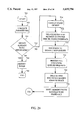
- FIG. 7 is a flow chart illustrating the steps for performing an output operation according to the present invention.
- FIG. 8 is a diagram showing the format of the NIOP Input Queue and NIOP Output Queue.
- FIG. 9A is a diagram of an NIOP Queue entry at initiation time.
- FIG. 9B is a diagram of an NIOP Queue entry at completion time.
- FIG. 10 is a diagram of the format of a Transfer Descriptor Word.
- FIG. 11 is a block diagram showing an example of an Input Message Program with three message segments.
- FIG. 12 is a diagram of the format of a Queue Bank used as an NIOP buffer.
- FIG. 13A is a diagram of the format of the Message Program Buffer Control Word.
- FIG. 13B is a diagram of the format of a Transfer Descriptor Word Template.
- FIG. 13C is a diagram of the format of an Access Control Word.
- FIG. 14A is a diagram of the format of the Network I/O Processing Queue Bank.
- FIG. 14B is a diagram of the format of the NIOP Input Queue/NIOP Output Queue Message Program Buffer Pointer.
- FIG. 15 is a diagram of the format of a Message Program Buffer.
- FIG. 16 is a diagram of the format of the Universal Processor Interface Control Table.
- FIG. 17 is a diagram of the general format of the Channel Address Word Area.
- FIG. 18 is a diagram of the format of the Channel Program Channel Status Word.
- FIG. 19 is a diagram of the format of the NIOP Queue Channel Status Word.
- FIG. 20 is a diagram of the format of the Enable/Disable Network Interface Channel Address Word.
- FIG. 21 is a diagram of the format of a Queue Descriptor Packet.
- FIG. 22 is a flow chart of the steps performed by the Network I/O Microcode to transfer input messages from the Network Interface to memory.
- FIG. 23 is a flow chart of the steps performed by the Network I/O Microcode to transfer output messages from memory to the Network Interface.
- FIG. 24 is a diagram of the format of the INIT$NETWORK packet.
- FIG. 25 is a flow chart illustrating the steps for initializing a Network Interface.
- FIG. 26 is a diagram of the format of the RSET$NETWORK packet.
- FIG. 27 is a flow chart illustrating the steps for resetting a Network Interface.
- FIG. 28 is a diagram of the format of the TERM$NETWORK packet.
- FIG. 29 FIG. 30 are flow charts illustrating the steps for terminating a Network Interface.
- FIG. 31 is a diagram of the format of the NET$IN/NET$OUT packet.
- FIG. 32 and FIG. 33 are flow charts illustrating the steps for obtaining input from and sending output to a Network Interface.
- FIG. 34 is a block diagram showing sample Queue Banks for sending output messages.
- NIOPQB NIOP Queue Bank
- FIG. 1 is a block diagram illustrating the computer hardware and software components of the environment in which the present invention operates.
- a Computer System 10 is connected to various Peripheral Devices 12 and to at least one Network 14.
- the Computer System 10 is a 2200 Series Enterprise Server commercially available from Unisys Corporation, although other large scale computer systems may also be used.
- the Peripheral Devices 12 consist of magnetic and optical disk drives, magnetic tape drives, printers, and other devices directly connected to the Computer System 10.
- Each Network 14 may be a Local Area Network (LAN), a Metropolitan Area Network (MAN), or a Wide Area Network (WAN), each of which may support a variety of communications network interfaces such as the Fiber Distributed Data Interface (FDDI), Ethernet, and Asynchronous Transfer Mode (ATM) standards.
- FDDI Fiber Distributed Data Interface
- Ethernet Ethernet
- ATM Asynchronous Transfer Mode
- NIC Network Interface Card
- IP Instruction Processor
- MSU Main Storage Unit
- NIOP Network Input/Output Processor
- the IP 22 executes Application Programs 28 started by the users of the Computer System. During their execution by the IP, Application Programs 28 typically require services provided by the Operating System Executive (Exec) 30. For example, when an Application Program needs to read data from or write data to one of the Peripheral Devices 12, the Application Program calls an Exec I/O service to perform the requested function. If an Application Program needs to send a message to or receive a message from any other computer system (such as a Personal Computer 16 or Workstation 18) connected to the Network 14, the Application Program uses a service provided by the Communications Program 32.
- the Communications Program 32 is a computer program that provides network communications-related I/O services and is optimized for contemporary cooperative processing environments.
- the Communications Program 32 uses either Network I/O Processor (NIOP) Exec Services 34 or NIOP Support Instructions 36 to implement Application Program requests for communications I/O.
- NIOP Exec Services 34 provides operating system-level constructs to initialize, recover, and terminate a Network Interface and to control communications I/O over a Network Interface.
- NIOP Support Instructions 36 are additions to the Instruction Set Architecture of the Computer System 10 to allow the Communications Program 32 to directly control communications I/O incurring less system overhead than the NIOP Exec Services for controlling communications I/O.
- Either NIOP Exec Services 34 or NIOP Support Instructions 36 are supported in a given implementation of the Network I/O processing architecture. However, initialization, reset, and termination services common to both are used. More details of the NIOP Exec Services 34 and the NIOP Support Instructions 36 are provided below.
- the Network I/O Processor (NIOP) 26 contains Channel Microcode 38 and Network I/O Microcode 40, both of which respond to requests from the IP 22 to communicate with the Peripheral Devices 12 and the Network 14, respectively.
- the Channel Microcode 38 utilizes a Channel Adapter (CA) component.
- CA Channel Adapter
- the CAs support a number of industry standards applicable to I/O, including the Block Multiplexer Channel (BMC) standard (as specified in the Federal Information Processing Standards For I/O Channel Interfaces, FIPS60), the Intelligent Peripheral Interface (IPI) standard (as specified in IPI Physical Level, X3.129--1986; IPI Device-Generic Command Set for Magnetic and Optical Disk Drives, X3.132--1987; and IPI Device-Genetic Command Set for Magnetic Tape Drives, X3.147--1988), the Small Computer System Interface (SCSI) standard (as specified in X3.131--1986), and the Unisys Systems Connection (USCON) standard (supporting the Enterprise Systems Architecture/390 ESCON I/O Interface, IBM#SA22-7202).
- BMC Block Multiplexer Channel
- IPI Intelligent Peripheral Interface
- IPI Intelligent Peripheral Interface
- SCSI Small Computer System Interface
- USB Unisys Systems Connection
- the Network I/O Microcode 40 utilizes the Network Interface Controller 46, which is essentially a counterpart to the NIC 20 contained in a Personal Computer 16 or a Workstation 18. There may be more than one Network Interface Controller 46 per NIOP, although only one is shown in FIG. 1. NICs may be bundled in physical, configurable entities called Network Channels. Each instance of a Network Interface Controller 46 and its connection to the Network 14 is called a Network Interface.
- the Network Interface embodies the logic which provides the interface from the Network I/O Microcode to the Network 14.
- the Network Interface implements the physical layer of the network protocol. For example, one NIOP 26 may have a Network Interface Controller communicating over an FDDI-based network and another Network Interface Controller communicating over an Ethernet-based network.
- the NIOP 26 concurrently handles requests to communicate with Peripheral Devices 12 and also the Network 14. These communications paths have very different requirements for initialization, input, output, termination, and error recovery, but are efficiently handled by one processing component, the NIOP 26.
- FIG. 2 is a block diagram illustrating the major components of the present invention.
- the Communications Program 32 is the controller of every Network Interface.
- the NIOP Initialization, Reset, and Termination Services 57 provides initialization, termination, and NIOP error handling services.
- Network I/O initiation services are provided by the NIOP Exec Services 34 (for Exec Service-based systems) or the NIOP Support Instructions 36 (for Instruction-based systems), both of which are represented on FIG. 2 as NIOP Input and Output Services 58.
- Message data to be transferred to the Network reside in NIOP message buffers made up of Queue Banks.
- a Queue Bank (not shown) is a unit of storage in the Main Storage Unit 24 consisting of a Control Area and a Text Area.
- the Control Area (which is transparent to Application Programs) contains control fields used by the Instruction Processor (IP) 22 in performing queuing and I/O management functions.
- the Text Area holds a description of the message to be held in the Queue Bank and the message data itself.
- the message data is described by one or more Access Control Words (ACWs).
- ACWs Access Control Words
- the NIOP Input Queue 59 is used to pass Input Message Programs (IMPs) from the Communications Program to the Network I/O Microcode.
- IMPs Input Message Programs
- the NIOP Input Queue 59 resides in the Main Storage Unit.
- An IMP is a description of the storage area in the Main Storage Unit where the Network I/O Microcode writes input messages received from the Network.
- An IMP consists of a series of Transfer Descriptor Words (TDWs), one for each portion of the storage area where portions of input messages are written.
- TSWs Transfer Descriptor Words
- the NIOP Output Queue 60 is used to pass Output Message Programs (OMPs) from the Communications Program to the Network I/O Microcode.
- OMPs Output Message Programs
- the NIOP Output Queue 60 also resides in the Main Storage Unit.
- An OMP is a description of the storage area where an output message to be sent over the Network is held.
- An OMP consists of a series of TDWs, one for each portion of the storage area from where output messages are retrieved.
- the Network I/O Microcode Upon completion of an output message transfer, the Network I/O Microcode writes the completion status to the NIOP Output Queue 60. For output transfers, the Network I/O Microcode is allowed to present an early successful completion status.
- the Network I/O Microcode can increase its efficiency because the Network I/O Microcode can obtain multiple NIOP Output Queue entries, write successful completion status for each, and then actually transmit the data over the network at a later point in time. (If the Network I/O Microcode cannot send the data, the error is handled like an error in transmission over the network by the upper layer protocol.)
- the first TDW is located in the NIOP Input Queue/NIOP Output Queue entries. Subsequent TDWs, if any, reside within a Message Program Buffer (MPB) (not shown in FIG. 2). There is an MPB associated with each NIOP Input Queue/NIOP Output Queue entry.
- MPB Message Program Buffer
- NIOPQB NIOP Queue Bank
- the Universal Processor Interface Control Table (UPICT) is used to pass initialization and termination functions and status between the Exec 30 and the Network I/O Microcode 40.
- the Universal Processor Interface (UPI) is the means by which various types of processors in the Computer System 10 communicate with an IP 22.
- the UPI is a processor-to-processor signal used by a processor to notify another processor that there is a message in a mailbox requiring its attention.
- the UPICT is a control structure that has the IP-to-NIOP and the NIOP-to-IP mailboxes for a particular NIOP. There is one UPICT per NIOP.
- the UPICT resides in the Main Storage Unit 24.
- Exec services For Network Interface initialization and termination, three Exec services are defined. These services are applicable to NIOPs supporting either Exec Service-based systems or Instruction-based systems.
- Software interface 64 represents the call from the Communications Program to these three services.
- the INIT$NETWORK Exec service is used by the Communications Program 32 to initialize a Network Interface.
- the RSET$NETWORK Exec service is used by the Communications Program 32 to reset a Network Interface.
- the TERM$NETWORK Exec service is used by the Communications Program 32 to terminate a Network Interface.
- NIOP Exec Services 34 are defined for placing IMPs and OMPs on the two NIOP queues.
- Software interface 66 represents the subroutine call from the Communications Program to these two services.
- the NET$IN Exec service builds IMPs, enqueues IMPs to an NIOP Input Queue 58, and releases completed IMPs.
- the NET$OUT Exec service builds OMPs, enqueues OMPs to an NIOP Output Queue 60, and releases completed OMPs.
- the NIOP Support Instructions 36 replace the NIOP Exec Services 34 to provide instructions whose functions are equivalent to NET$IN and NET$OUT.
- These instructions allow a non-privileged program, such as the Communications Program 32, to directly interface with the Network I/O Processor without the risk of corruption of memory (e.g., the Communications Program cannot alter the real (physical memory) addresses in an IMP (which could cause input messages to be written to the wrong area of memory).
- the Communications Program 32 retrieves Network Interface status by directly reading the status placed in the NIOP queues by the Network I/O Processor.
- Network Interface functions such as station management and utility functions are passed between the Communications Program and the Network Interface Controller 46 (not shown in FIG. 2) via specially designated messages. These messages receive no special processing by the Exec, the NIOP Support Instructions, or the Network I/O Processor.
- FIG. 3 is a flow chart illustrating the steps for initializing a Network Interface according to the present invention.
- Initialization 68 of the Network Interface readies the NIOP to accept input from and send output to the Network.
- the Communications Program 32 acquires Queue Banks from a Computer System Available Queue for use as NIOP buffers.
- the NIOP buffers store input and output message data. There is no predetermined or pre-existing relationship between Queue Banks and a Network Interface.
- the Communications Program exclusively assigns the Network Interface(s) described in its configuration fie.
- the processes in the Communications Program which monitor the NIOP queues are started at Step 74.
- the Communications Program requests the Exec to initialize the Network Interface by building the NIOP Queue Bank (NIOPQB) at Step 76, and by signaling the NIOP to initialize the Network Interface at Step 78.
- NIOPQB NIOP Queue Bank
- the gate addresses for NET$IN and NET$OUT and the virtual addresses of the NIOPQB and a data structure called the NIOP Control Bank (NIOPCB) (described further below) are returned.
- the virtual addresses of the NIOPQB and NIOPCB are returned.
- the Communications Program initializes the Network Interface by sending maintenance messages in Output Message Programs through the Network I/O Microcode to the Network Interface at Step 80. Message transfer can now begin through the Network Interface.
- FIG. 4 is a block diagram illustrating an input operation for the present invention.
- the system components used to get input data from the Network 14 include the Network Interface (N/W INFC) 46, the Network I/O Microcode 40 being executed by the NIOP, the NIOP Input Queue 59, and the Communications Program 32.
- FIG. 5 is a flow chart illustrating the steps for performing an input operation according to the present invention.
- the Input operation 86 commences with Step 88, where a Queue Bank is selected for receiving an input message.
- Step 90 Access Control Words (ACWs) 56 describing the Message Area 84 of the Queue Bank (as shown on FIG. 4) are built by the Communications Program.
- ACWs Access Control Words
- An NIOP Use Count is then incremented at Step 92 to indicate that the Queue Bank real addresses are in use by the NIOP.
- the ACWs in the Queue Bank are converted to an Input Message Program (IMP) (which is a series of TDWs in the MPB) at Step 94.
- IMP Input Message Program
- the IMP is enqueued to the NIOP Input Queue by copying the first TDW from the MPB to the NIOP Input Queue entry and writing the Message ID to the NIOP Input Queue entry at Step 96. (Note that the Valid bit (discussed further below) was set in this first TDW when it was written to the MPB).
- Steps 92 through 96 are accomplished by the Build IMP (BIMP) and Enqueue To NIOP Input Queue (ENIQ) instructions described below.
- BIMP Build IMP
- ENIQ Enqueue To NIOP Input Queue
- these steps are performed by the NET$IN Exec service 34 for the particular interface, as called by the Communications Program 32.
- IMPs are dequeued from the NIOP Input Queue 59 by the Network I/O Microcode at Step 100.
- the input message is written at Step 102 by the Network I/O Microcode 40 to the area described by the IMP.
- the status of the data transfer is then written to the NIOP Input Queue entry at Step 104.
- Step 110 the Network I/O Microcode presents an interrupt to the Exec 30. This interrupt is an indication that a Communications Program process needs to be activated to process the input message. If the interrupt flag is not set, No path 112 is taken to Step 114. At this step, the Communications Program 32 reads the status from the NIOP Input Queue. Next, at Step 116, the input message is processed by the Communications Program. Normal storage read instructions are used to access the NIOP Input Queue in the Main Storage Unit 24.
- Step 118 the IMP is released, Queue Bank NIOP Use Counts are decremented for each Queue Bank in the IMP and the NIOP Input Queue entry is made available for reuse.
- this is accomplished by the Release Input Message Program (RIMP) instruction.
- RIMP Release Input Message Program
- Exec Service-based systems this is accomplished by a future call to the NET$IN service.
- FIG. 6 is a block diagram illustrating an output operation for the present invention.
- the system components used to send output data to the Network 14 include the Network Interface Controller 46, the Network I/O Microcode 26 being executed by the NIOP, the NIOP Output Queue 60, and the Communications Program 32.
- FIG. 7 is a flow chart illustrating the steps for performing an output operation according to the present invention.
- the Output operation 120 commences with Step 122. At this step, the output message is written to one or more Queue Banks within the Message Area 84 by the Communications Program 32 and the Application Program.
- the Application Program writes the application-level message to be sent, and the Communications Program writes the network protocol segments needed to deliver the message over the Network and the Access Control Words (ACWs).
- ACWs Access Control Words
- the ACWs 56 describing the Message Area are built at Step 124.
- An NIOP Use Count for each Queue Bank in the output message is incremented by Step 126 to indicate that the Queue Bank real addresses are in use by the NIOP.
- the ACWs are converted to an Output Message Program (OMP).
- OMP is enqueued to the NIOP Output Queue by the Communications Program 32 by copying the first TDW from the MPB to the NIOP Output Queue entry and writing the Message ID to the NIOP Output Queue entry at Step 130. (Note that the Valid bit (discussed further below) was set in this first TDW when it was written to the MPB).
- Steps 126 through 130 are accomplished by the Build OMP (BOMP) and Enqueue To NIOP Output Queue (ENOQ) instructions described below.
- BOMP Build OMP
- ENOQ Enqueue To NIOP Output Queue
- these steps are performed by the NET$OUT Exec service 34 for the particular interface, as called by the Communications Program 32.
- the OMP is dequeued from the NIOP Output Queue 60 by the Network I/O Microcode 40.
- the output message is then transferred to the Network Interface (N/W INFC) 46.
- Step 138 the status of the transfer is written to the NIOP Output Queue entry by the Network I/O Microcode. After the status is written, at Step 139, the output message is transmitted over the Network.
- the Communications Program 32 reads the status from the NIOP Output Queue at Step 140 and processes it.
- Step 142 the OMP is released, Queue Bank NIOP Use Counts are decremented for each Queue Bank in the OMP, and the NIOP Output Queue entry is made available for reuse.
- this is accomplished by the Release Output Message Program (ROMP) instruction.
- EMP Release Output Message Program
- Exec Service-based systems this is accomplished by a future call to the NET$OUT service.
- Hardware/microcode errors detected in the Network Interface 46 component of the NIOP 26 are reported to the Communications Program using the NW INFC RA 156 in the NIOP Input Queue or NIOP Output Queue entry used for the message transfer.
- the protocol used for the Network handles message recovery in the event of an error.
- the Communications Program ignores the input message if an error is detected during reception and assumes the message transfer completed successfully for output messages.
- Other hardware/microcode errors that are detected are reported to the Communications Program using the NIOP RA 154 in the NIOP Input Queue or NIOP Output Queue entry used for the message transfer and to the Exec 30 in the UPI Control Table 62.
- the Communications Program's response to these errors is to down, then reinitialize the Network Interface.
- For errors detected in the input message data (such as checksum errors), the error is reported to the Communications Program in the NIOP Input Queue entry used for the message transfer.
- Network protocol is then used to handle message recovery and the Communications
- the Exec 30 provides two services to support the error handling needed by network input/output.
- the first service provides for the resetting of a Network Interface.
- the second service provides for the termination of the Communications Program's use of a Network Interface.
- the NIOP Input Queue 58 is used to pass Input Message Programs (IMPs) from software being executed by the Instruction Processor 22 to the Network I/O Microcode 40 and completion status from the Network I/O Microcode to the IP-based software.
- An IMP is a description of the storage area in the Main Storage Unit 24 to which the NIOP writes input messages received from the Network.
- the IMP consists of one or more Transfer Descriptor Words (TDWs).
- the NIOP Output Queue 60 is used to pass Output Message Programs (OMPs) from software being executed by the Instruction Processor 22 to the Network I/O Microcode 40 and completion status from the Network I/O Microcode to the IP-based software.
- OMP also consists of one or more TDWs.
- NIOP Input Queue and NIOP Output Queue are 4096 36-bit words long and consist of 1024 four-word entries. The queues begin at 4096-word boundaries in memory contained in the Main Storage Unit.
- the Network I/O Microcode is passed the real address of the first NIOP Input Queue or NIOP Output Queue entry to be alequeued via an Enable/Disable Network Interface Order Code.
- Each queue entry contains a Valid bit, which indicates the validity of the queue entry. The validity of the Valid bit is from the Network I/O Microcode's perspective. If the Valid bit is set, the Network I/O Microcode has a queue entry to process.
- the NIOP Exec Services 34 for Exec service-based systems or the NIOP Support Instructions 36 (for Instruction-based systems) set the Valid bit when an IMP is enqueued to an NIOP Input Queue entry or when an OMP is enqueued to an NIOP Output Queue entry. If the Valid bit is clear in the queue entry addressed by the Network I/O Microcode's dequeue pointer, then the Network I/O Microcode polls the Valid bit. When the Valid bit is set, the Network I/O Microcode reads the queue entry and performs the message transfer request. Upon transfer completion, the Network I/O Microcode clears the Valid bit, which indicates that the queue entry contains the completion status.
- FIG. 9A is a diagram of an NIOP Queue entry at initiation time.
- Bits 0-35 of Words 0-1 hold the First Transfer Descriptor Word (TDW) 144 of an IMP or OMP.
- Bit 17 of Word 0 holds the Valid bit 146.
- the Valid bit is used by the NIOP to determine if the queue entry contains a valid message program. The Valid bit is cleared by the NIOP when the completion status is written.
- Bits 0-35 of Word 2 hold the Next TDW Pointer 148. If the Data Chain (DC) bit (discussed below) is set in the First TDW, this field holds the real address of the second TDW of the IMP (or OMP). If the DC bit is clear in the First TDW, this field is ignored.
- DC Data Chain
- FIG. 9B is a diagram of an NIOP Queue entry at completion time. Words 1 through 3 of the entry remain as in FIG. 9A. Bits 0-16 of Word 0 are now Reserved 152. Bits 18-26 of Word 0 hold an NIOP Recovery Action (NIOP RA) 154.
- NIOP RA NIOP Recovery Action
- This field is used by the Communications Program to check the completion status of the message transfer. When this field is zero, no recovery action is required because the transfer is assumed to be successfully completed. (Note that the NIOP is allowed to report an error in the data transfer asynchronously) If this field is non-zero, the field specifies a recovery action to be attempted by the NIOP Exec Services and/or the Communications Program.
- NW INFC RA Network Interface Recovery Action
- Transfer Descriptor Words are the entries in the Input and Output Message Programs. TDWs hold the real address and byte length of a message buffer (or portion thereof), and control information. There is one or more TDWs for each segment of a message.
- FIG. 10 is a diagram of the format of a Transfer Descriptor Word.
- the Byte Offset (BYTE OFS) field 157 in Bits 0-1 of Word 0, specifies the byte offset in the first word of an output message segment. If the Byte Offset value is zero, the location of the first byte transferred is Bits 1-8 of the first word of the message segment. If the Byte Offset value is one, the location of the first byte is Bits 10-17.
- the Byte Offset value is two, the location of the first byte is Bits 19-26. If the Byte Offset value is three, the location of the first byte is Bits 28-35.
- the Byte Offset must be zero. Bits 2-8, 10-16, and 18-21 of Word 0 of the TDW are Reserved (RES).
- the Data Chain (DC) field 158 in Bit 9 of Word 0, if set, indicates that another TDW follows this TDW. If DC is clear, it indicates that this TDW is the last TDW in the IMP or the OMP.
- the Valid bit 159 is stored in Bit 17 of Word 0.
- the Valid bit is used by the NIOP to determine if the NIOP Input Queue/NIOP Output Queue entry contains a valid IMP/OMP.
- the Valid bit is cleared by the NIOP when the completion status is written. For all other TDWs, this bit is reserved.
- the Byte Length field 160 in Bits 22-35 of Word 0, indicates the number of bytes in the portion of the message buffer described by the TDW. The maximum area described by a TDW is 16,384 bytes.
- the Real Address field 161, in Bits 0-35 of Word 1 specifies the real address in the Main Storage Unit of the first word of the message segment described by the TDW.
- FIG. 11 is a block diagram showing an example of an Input Message Program with three message segments.
- the NIOP Input Queue entry 163 has its First TDW field 144 pointing to the first word of the message segment.
- the First TDW has its DC field set to one.
- the Next TDW Pointer field 148 points to another TDW 165, which points to the second message segment 166.
- the second TDW has its DC field set to one, indicating it is part of a data chain.
- the next contiguous word in the real address space holds the final TDW 167, which points to the third message segment 168.
- This final TDW has its DC field set to zero, indicating that there are no more TDWs in the IMP.
- An OMP may consist of a chain of TDWs in a similar manner.
- the NIOP Input Queue/NIOP Output Queue/MPB format requires that the Network I/O Microcode accesses the MPB only if more than one TDW is required to
- FIG. 12 is a diagram of the format of a Queue Bank used as an NIOP buffer.
- the first 256 words of the Queue Bank represent the Control Area and the remaining words represent the Text Area.
- Within the Control Area are a plurality of Control Fields 200 and space Reserved For Software 202 use.
- a Message Program Buffer (MPB) Control Word 204 is in Word 117 of the Control Area.
- MPB Message Program Buffer
- 13A is a diagram of the format of the MPB Control Word.
- the MPB Control Word is used to manage a Queue Bank's use in MPBs. Bits 0-4 of the MPB Control Word must be zero 206.
- the MPB Trap field 208 in Bit 5, is used to delay the use of this Queue Bank in an IMP or OMP until the memory mangament function is done managing memory pages in the Queue Bank. Otherwise, the Build IMP or Build OMP instruction or the NET$IN or NET$OUT service attempts to add the specified Queue Bank to the IMP or OMP, respectively.
- the Software State field 210 in Bits 6-17, is used to hold Exec-internal state.
- the NIOP Use Count field 212 is an unsigned integer which indicates the number of times the Queue Bank is active as an IMP/OMP buffer.
- the NIOP Use Count is incremented by a Build IMP or Build OMP instruction and decremented by a Release IMP or Release OMP instruction.
- the NIOP Use Count is also incremented and decremented by NET$IN and NET$OUT Exec services.
- Transfer Descriptor Word Templates are used by Build IMP and Build OMP instructions to translate Queue Bank relative addresses to real addresses used in IMP or OMP Transfer Descriptor Words (TDWs).
- the NET$IN and NET$OUT Exec services also use TDWTs to build TDWs.
- TDWTs there are 65 TDWTs supported in each Queue Bank, numbered from TDWT 0 214 to TDWT 64 216. These TDWTs describe each page of the Queue Bank Text Area. Each TDWT consists of two words.
- FIG. 13B is a diagram of the format of a Transfer Descriptor Word Template.
- Bits 0-21 of Word 0 of a TDWT must be zero 218.
- the Byte Length field 220 in Bits 22-35 of Word 0, indicates the number of valid bytes of message area in the memory page associated with this TDWT. Any non-zero value indicates that the full page is resident in memory (although some of the page may not be accessible because it holds the Queue Bank Control Area or is beyond the Queue Bank Upper Limit).
- the Real Address field 222 in Bits 0-35 of Word 1, indicates the real address of the first word of the page associated with this TDWT.
- Words 248 through 255 of the Control Area are Reserved For Hardware 224 use.
- Words 0 through 7 of the Text Area are Reserved For Software 226 use.
- the Access Control Word (ACW) Count field 228, in Word 8 of the Text Area, is the highest count of valid ACWs for this Queue Bank.
- Word 9 of the Text Area is Reserved For Hardware 230.
- ACWs are the Communications Program's description of a message segment. There is space for multiple ACWs within the Text Area of a Queue Bank. Each ACW corresponds to a message segment in the Queue Bank. These ACWs are represented on FIG. 12 as ACW 0 232 through ACW N-1 234.
- FIG. 13C is a diagram of the format of an ACW.
- Word 0 of each ACW holds a Byte Length field 238.
- the Byte Length is the number of bytes in the message segment.
- An Addressing Exception error message is generated if the Byte Length is not a multiple of four.
- For the NET$IN Exec service an error status is generated if the Byte Length is not a multiple of four.
- the Byte Offset field 240 is stored in Word 1 of the ACW. This field is the byte offset of the message segment. The Byte Offset is relative to the first byte of the Queue Bank Text Area. For both Exec service-based systems and instruction-based systems, an Addressing Exception error message is generated if the Byte Offset is not a multiple of four.
- the NIOP Queue Bank (NIOPQB)
- the Network I/O Processor (NIOP) Queue Bank (NIOPQB) contains the NIOP Queues and pointers to Message Program Buffers (MPBs) (which hold IMPs/OMPs and various control information).
- MPBs Message Program Buffers
- FIG. 14A is a diagram of the format of the NIOP Queue Bank. There are four pages of memory in the NIOPQB. The NIOP Input Queue, NIOP Output Queue, and associated MPB pointers are sized to fit into one memory page (which, in the preferred embodiment, is 4096 words).
- the NIOP Input Queue 242 is stored in Page 0 and the NIOP Output Queue 244 is stored in Page 1.
- the NIOP Input Queue MPB Pointers 246 are stored in Page 2 and the NIOP Output Queue MPB Pointers 248 are stored in Page 3.
- FIG. 14B is a diagram of the format of the NIOP Input Queue/NIOP Output Queue Message Program Buffer Pointer.
- the NIOP Input Queue/NIOP Output Queue MPB Pointers are used to access the MPB associated with the corresponding NIOP Input Queue/NIOP Output Queue entry. Bits 0-35 of Word 0 250 and Word 1 252 are Reserved For Software use.
- Bits 0-17 of Word 2 254 Must Be Zero. Bits 18-35 of Word 2 and Bits 0-35 of Word 3 hold the MPB Base Address 256.
- the MPB Pointers are initialized by Exec software and are not modified by the NIOP Support Instructions.
- FIG. 15 is a diagram of the format of a Message Program Buffer. Bits 0-4 of Word 0 Must Be Zero 258.
- the NIOP Controlled (NC) field 260 is stored in Bit 5 of Word 0. The purpose of the NC field is to coordinate usage of the NIOP Input Queue/NIOP Output Queue entries between multiple host software threads.
- the First, Next, and Max TDW Addresses are used to coordinate the writing of IMP/OMP TDWs in the MPB.
- the Max TDW Address field 270 in Bits 18-35 of Word 2, hold the address (relative to the MPB) of the last IMP/OMP TDW location. This address is initialized by Exec software and not modified by the NIOP Support Instructions or the NIOP Exec Services.
- the Next TDW Address field 272 in Bits 18-35 of Word 3, hold the address (relative to the MPB) of the IMP/OMP TDW location where the Build IMP/OMP instructions will write the next TDW. This address is incremented to point to the next, unused TDW location after the Build IMP/OMP instruction mites all TDWs for a Queue Bank. This address is reset to equal the First TDW Address by the Release IMP/OMP instructions.
- the Next TDW Address is incremented by two words as TDWs are added.
- Word 4 is Reserved 274.
- the First, Next, and Max Queue Bank Pointers are used to coordinate the writing of Queue Bank Pointers in the MPB.
- QBP fields have the same format as the MPB Pointer shown in FIG. 14B, except Bits 18-35 of Word 2 and Bits 0-35 of Word 3 hold a Queue Bank Base Address instead of a MPB Base Address.
- the Queue Bank Base Address is the absolute address of the first Control Area word of the Queue Banks in the IMP/OMP.
- the First QBP Address is initialized by Exec software and not modified by the NIOP Support Instructions.
- the Max QBP Address field 278, in Bits 18-35 of Word 6, holds the address (relative to the MPB) of the last IMP/OMP QBP location. This address is initialized by Exec software and not modified by the NIOP Support Instructions.
- the Next QBP Address field 280, in Bits 18-35 of Word 7, holds the address (relative to the MPB) of the QBP location where the Build IMP/OMP instructions will write the next QBP. This address is incremented by four as Build IMP/OMP instructions add QBPs to the MPB and is reset to equal the First QBP Address by the Release IMP/OMP instructions.
- the storage area in Words 8 through N 282 holds the TDWs and QBPs. The ability to dynamically allocate space to QBPs and MPBs accommodates varying numbers of Queue Banks and TDWs per IMP/OMP. Bits 0-17 of Word 1, 2, 3, 5, 6, and 7 Must Be Zero.
- the Universal Processor Interface (UPI) Control Table (UPICT) is used for communication between Instruction Processor (IP) software and the Network I/O Processor (NIOP).
- IP Instruction Processor
- NIOP Network I/O Processor
- the UPICT accommodates the dual network and channel functionality.
- An NIOP has a single UPICT, even if it is being used in a dual mode of operation.
- FIG. 16 is a diagram of the format of the Universal Processor Interface Control Table.
- the Channel Address Word (CAW) Area 300 in Bits 0-35 of Words 0-3, is used by IP-based software to send Channel Address Words (CAWs) to the NIOP.
- CAW Channel Address Word
- the Channel Status Word (CSW) Area 302, in Bits 0-35 of Words 8-15, the Extended CSW Area 304, in Bits 0-35 of Words 16-23, and the Extended Device Status Buffer 306, in Bits 0-35 of Words 24 through the end of the UPICT, are used by the NIOP to report status to IP-based software.
- Bits 0-35 of Words 4-7 are Reserved 308. Fields in the CAWs and CSWs indicate the channel or Network Interface associated with the CAW/CSW.
- FIG. 17 is a diagram of the general format of the Channel Address Word Area.
- the CAW Area is a four-word structure used to pass an Order Code (OC) to the NIOP.
- the Order Code represents a request by the IP-based software for the NIOP to perform an I/O-related action.
- the contents of the CAW Area are dependent on the specific Order Code to be sent.
- the Order Code 310 is stored in Bits 9-17 of Word 0 of the CAW Area.
- the Valid CAW (VC) bit 312, stored in Bit 0 of Word 3, is used to indicate that the CAW is ready to be processed by the NIOP. Bits 1-4 of Word 3 are reserved (RES) 314.
- the Valid Condition Code (VCC) bit 316 stored in Bit 5 of Word 3, is used to indicate that the NIOP has returned a Condition Code in response to the CAW.
- the Condition Code (CC) field 318 stored in Bits 6-11 of Word 3, is written by the Network I/O Microcode as a response to the CAW.
- Condition Codes vary according to the specific Order Codes being used. Generally, the Condition Code indicates that the Order Code was successfully executed or that an error or hardware fault has occurred. All other fields in the CAW are Order Code Dependent (OC DEP), meaning that they are used for different purposes depending on which Order Code has been specified.
- O DEP Order Code Dependent
- FIG. 18 is a diagram of the format of the Channel Program Channel Status Word.
- the Channel Program Channel Status Word (CPCSW) is used to report status for NIOP transfers.
- the Interrupt Code (IC) 320 in Bits 0-5 of Word 0, indicates that this CSW is a CPCSW when IC is zero.
- the NIOP UPI Number 322, in Bits 6-17 of Word 0, contains the UPI Number of the NIOP.
- the Network Interface Identifier (ID) 324 in Bits 18-35 of Word 0, identifies the Network Interface associated with the transfer for which status is being reported.
- the Network Interface Identifier format allows for multiple Network Interfaces to be supported on a single physical I/O channel.
- the Network Interface Identifier contains six bits used as a channel number identifier and four bits used as an interface number identifier. The final eight bits of the Network Interface Identifier must be zero. Bits 0-35 of Word 1 326, Word 3 328, and Word 7 330, and Bits 6-35 of Word 2 332 are Reserved.
- the Recovery Action (REC ACTION) field 334 indicates the result of a Network Interface transfer. Bits 0-35 of Word 4 336 and Word 5 338 contain a Hardware Dependent Status. When the Recovery Action field is non-zero, this field specifies the cause of the non-zero Recovery Action.
- Bits 0-35 of Word 6 hold a Real Address/Hardware (HW) Dependent Status 340.
- HW Real Address/Hardware
- FIG. 19 is a diagram of the format of the NIOP Queue Channel Status Word.
- the NIOP Queue Channel Status Word (NQCSW) is used to report the NIOP queue conditions. These conditions include finding the Interrupt Flag set following the transfer of an input message and detecting a fault while accessing an NIOP queue. If an error is detected on an NIOP Queue access, an NQCSW is written to the UPI Control Table and the Network Interface is disabled. For the NQCSW, the Interrupt Code (IC) 342 is set to sixteen decimal. When the Recovery Action (REC ACTION) field 344 is non-zero, a fault occurred on a queue reference. The Internal Status field 346 indicates the cause of the CSW. The Internal Status field has the following sub-fields.
- Bits 6-11 and Bits 13-14 must be zero. Bit 12 of the Internal Status is the Interrupt bit. If the Interrupt Flag has been set in the Interrupt Control Word, then an NQCSW is generated to return the status to the IP-based software. The Interrupt Control Word is used by the NIOP to determine if IP-based software requires a positive indication that the completion status has been stored to the NIOP Input Queue. The NIOP is passed the real address of the Interrupt Control Word for a Network Interface via the Enable/Disable Network Interface Order Code. The Interrupt Control Word must have zeroes in Bits 0-34 and the Interrupt Flag in Bit 35. If the Interrupt Flag is set when an input transfer is completed, then an NQCSW is presented in the UPICT (in addition to presenting completion status in the NIOP Input Queue). Otherwise, only the NIOP Input Queue completion status is presented.
- the Enable/Disable Network Interface is an Order Code used to direct the NIOP to enable or disable a Network Interface. This Order Code is inserted into the Channel Address Word Area within the UPI Control Table.
- FIG. 20 is a diagram of the format of the Enable/Disable Network Interface Channel Address Word.
- the Enable Network Interface (EN) flag 348 in Bit 0 of Word 0, indicates whether the Network Interface should be enabled or disabled. If EN is equal to one, the Network Interface specified by the Network Interface Identifier 350 is enabled. If EN is equal to zero, the Network Interface specified by the Network Interface Identifier is disabled.
- the Network Interface Identifier 350 is stored in Bits 18-35 of Word 0.
- the Clear On Disable (COD) flag 352 in Bit 1 of Word 0, is used to indicate a request for clearing the Network Interface under certain conditions. If EN 348 is zero and COD 352 is zero, the Network Interface is disabled, but not cleared. If EN is zero and COD is one, the Network Interface is disabled and cleared. If EN is one, then the COD 352 flag is ignored. Bits 2-8 of Word 0 are Reserved (RES) 354.
- the Order Code field 356, in Bits 9-17 of Word 0, specifies the action to be performed by the NIOP. The Order Code is 32 (decimal) for an EDNI.
- the Queue Descriptor Packet Address 358 in Bits 0-35 of Word 1 of this CAW, contains the starting real address of the Queue Descriptor Packet if EN 348 is one (i.e., it indicates enabling the Network Interface is to be performed). If EN is zero, this field is ignored. Bits 0-35 of Word 2 are Reserved 360.
- the Valid CAW (VC) flag 362, in Bit 0 of Word 3, is used to indicate that the CAW is ready to be processed by the NIOP. Bits 1-4 of Word 3 are Reserved (RES) 364.
- the Valid Condition Code (VCC) field 366 in Bit 5 of Word 3, is used to indicate that the NIOP has returned a Condition Code in response to the CAW.
- the Condition Code (CC) 368 stored in Bits 6-11 of Word 3, is ignored by the NIOP when the NIOP receives a CAW, but it is written by the NIOP as a response to a CAW.
- Valid Condition Codes include indications of successful execution of the request, occurrence of an NIOP-internal hardware fault, detection of a fault while attempting to read the CAW, the addressed Network Interface was unavailable, insufficient internal NIOP resources exist to support the Network Interface, and the NIOP disabled the NIOP Input Queue and NIOP Output Queue, but a Network Interface error was detected.
- FIG. 21 is a diagram of the format of a Queue Descriptor Packet.
- the NIOP Input Queue Start Address 372 and the NIOP Output Queue Start Address 374 are the real addresses of the first NIOP Input Queue and NIOP Output Queue entry, respectively, to be processed.
- the Interrupt Control Word Address 376 is the real address of the Interrupt Control Word.
- the NIOP uses the Queue Descriptor Packet to set up the NIOP Input Queue and the NIOP Output Queue during Network Interface enabling operations.
- the Network Interface When the EN field 348 is zero and the COD field 352 is zero, the Network Interface is disabled, but not cleared. All NIOP Input Queue, NIOP Output Queue, IMP, and OMP addresses are discarded. All active transfers of data are terminated and their status is discarded. The Network Interface state sufficient to allow a microstore dump is retained, and all network traffic is disabled. When the NIOP has initiated a status presentation for a Network Interface and the EDNI effort disables that Network Interface, the NIOP completes the status presentation.
- FIG. 22 is a flow chart of the steps performed by the Network I/O Microcode 40 to transfer input messages from the Network Interface to memory. These steps are performed after the Network Interface has been enabled by the Enable/Disable Network Interface Order Code.
- the Dequeue Pointer is a conceptual internal register set to point to the first queue entry to be processed as part of the EDNI Order Code.
- the size of an NIOP queue entry is four words, the address of the first queue entry (relative to the start of the NIOP Input Queue) is zero, and the address of the last queue entry (relative to the start of the NIOP Input Queue) is 4092.
- the NIOP reads the Valid bit of the NIOP Input Queue entry (QE) referenced by the Dequeue Pointer (Step 448). If the Valid bit is clear (Test Step 450), then the Yes path 452 is taken to Step 454, where the NIOP waits a predetermined amount of time. The NIOP then checks the Valid bit again at Step 448. If the Valid bit is not clear, then No path 456 is taken to Step 458.
- the Network I/O Microcode writes the input message to the storage area described by the Input Message Program (IMP) for the current NIOP Input Queue entry.
- IMP Input Message Program
- a control header embedded in the message indicates to the Communications Program whether the input message was received over the Network or is a control message generated by the Network Interface logic. If, at Test Step 462, errors occurred during the receipt of the input message, Yes path 464 is taken to Step 466, where the error is reported by writing recovery action (RA) error codes into the Network Interface Recovery Action (NW INFC RA) and NIOP Recovery Action (NIOP RA) fields of the NIOP Input Queue entry. If no errors were detected, then No path 468 is taken to Step 470. At this step, the NW INFC RA field of the NIOP Input Queue entry referenced by the Dequeue Pointer is set to zero. Next, at Step 472, the NIOP RA field of the same queue entry is set to zero. The valid bit of the NIOP Input Queue Entry is then cleared at Step 473. Processing continues with Test Step 474.
- RA recovery action
- NW INFC RA Network Interface Recovery Action
- NIOP RA NIOP Recovery Action
- Step 478 a Channel Program Channel Status Word (CPCSW) is written to the UPI Control Table to return the status of the input transfer to the Exec. Otherwise, the No path 480 is taken to Step 482.
- Step 482 the size of a queue entry is added to the Dequeue Pointer to cause the Dequeue Pointer to point to the next entry in the NIOP Input Queue.
- Step 484 If the Dequeue Pointer is now greater than the last queue entry ha the NIOP Input Queue (Test Step 484), then Yes path 486 is taken to Step 488, where the Dequeue Pointer is set back to the first entry in the NIOP Input Queue. Otherwise, the No path 490 is taken to Test Step 492.
- the Interrupt Control Word (ICW) Interrupt Flag is set, then Yes path 494 is taken to Step 496.
- an NIOP Queue CSW is written to the UPI Control Table (UPICT) to return the status of the transfer back to the IP-based software, and processing continues with the start of NIOP input processing. If the Interrupt Flag is not set, then No path 498 is taken back to the start of NIOP input processing.
- UPI Control Table UPI Control Table
- FIG. 23 is a flow chart of the steps performed by the Network I/O Microcode to transfer output messages from memory to the Network Interface. These steps are performed after the Network Interface has been enabled by the Enable/Disable Network Interface Order Code.
- the Network I/O Microcode After commencing NIOP Output 500, the Network I/O Microcode reads the Valid bit of the NIOP Output Queue queue entry (QE) referenced by the Dequeue Pointer (Step 502). If the Valid bit is clear (Test Step 504), then the Yes path 506 is taken to Step 508, where the Network I/O Microcode waits a predetermined amount of time. The Valid bit is checked again at Step 502. If the Valid bit is not clear, then No path 510 is taken to Step 512.
- QE NIOP Output Queue queue entry
- Step 508 the Network I/O Microcode waits a predetermined amount of time.
- the Valid bit is checked again at Step 502. If the Valid bit is not clear, then No path 510 is taken to
- the output message is described by its Output Message Program (OMP).
- OMP Output Message Program
- a control header embedded in the message indicates to the Network Interface whether the output message is to be sent over the Network or is a control message generated by the Communications Program. This step entails delivery of the output message to the Network Interface. Subsequently, the output message is transferred by the Network Interface over the Network. If, at Test Step 516, errors occurred during the sending of the output message, Yes path 518 is taken to Step 520, where the error is reported by writing recovery action (RA) error codes into the Network Interface Recovery Action (NW INFC RA) and NIOP Recovery Action (NIOP RA) fields of the NIOP Output Queue entry. If no errors were detected, then No path 522 is taken to Step 524.
- RA recovery action
- NW INFC RA Network Interface Recovery Action
- NIOP RA NIOP Recovery Action
- the NW INFC RA field of the NIOP Output Queue entry referenced by the Dequeue Pointer is set to zero.
- the NIOP RA field of the same queue entry is set to zero.
- the Valid bit of the NIOP Output Queue entry referenced by the Dequeue Pointer is set to zero. Processing continues with Test Step 528.
- Step 532 a Channel Program Channel Status Word (CPCSW) is written to the UPI Control Table to return the status of the output transfer to the Exec. Otherwise, the No path 534 is taken to Step 536.
- Step 536 the size of a queue entry is added to the Dequeue Pointer to cause the Dequeue Pointer to point to the next entry in the NIOP Output Queue.
- CPCSW Channel Program Channel Status Word
- Step 538 If the Dequeue Pointer is now greater than the last queue entry in the NIOP Output Queue (Test Step 538), then Yes path 540 is taken to Step 542, where the Dequeue Pointer is set back to the first queue entry in the NIOP Output Queue. Otherwise, the No path 544 is taken. In either case, processing continues with the start of NIOP output.
- Exec services supporting the Network I/O Architecture.
- Three of the services are used by both Exec Service-based systems and Instruction-based systems. These services are the INIT$NETWORK, RSET$NETWORK, and TERM$NETWORK services.
- the remaining two services, the NET$IN and NET$OUT services are used by Exec-based systems only.
- the INIT$NETWORK service initializes a Network Interface.
- the NET$IN service allows a caller to access the NIOP Input Queue to obtain input from the Network.
- the NET$OUT service allows a caller to access the NIOP Output Queue to send output to the Network.
- the RSET$NETWORK service resets a Network Interface.
- the TERM$NETWORK service terminates a Network Interface.
- the Communications Program uses the INIT$NETWORK Exec service to enable a Network Interface and to get the data structures initialized that are used to interact with the Network Interface.
- the Exec returns a gate address to be used for input, and a second gate address to be used for output.
- the Exec also returns the addresses of the NIOP Queue Bank (NIOPQB) and NIOP Control Bank (NIOPCB).
- the Exec converts the message descriptor into a message program (IMP or OMP) and places the message program into the queue entry (NIOP Input Queue or NIOP Output Queue) specified by the caller.
- NIOP Input Queue or NIOP Output Queue the queue entry specified by the caller.
- the Exec receives an NIOP Queue CSW from the Network I/O Microcode, and the NIOP Queue CSW is due to the Interrupt Flag found set upon completion of an input transfer, the Exec activates any Communication Processes waiting for input completion.
- the Communications Program is responsible for checking the NIOP Input Queue and the NIOP Output Queue for a completion status.
- the Exec When errors occur relating to the Network Interface, the Exec disables the Network Interface. The Exec marks all entries in the queues that have not received status from the NIOP with an appropriate error value. The Exec activates any Communications Program process waiting for input completion. The Communications Program must call the RSET$NETWORK Exec service to enable the interface again.
- the TERM$NETWORK Exec service call is used to terminate the use of an NIOP Network Interface and delete all of the control structures that were created to interface with the NIOP Network Interface. Because the TERM$NETWORK service deletes the NIOP structures returned on the INIT$NETWORK service call, the Communications Program may not use any of these structures after requesting a TERM$NETWORK.
- the INIT$NETWORK Exec service is used to enable a Network Interface and initialize the structures needed to use the Network Interface.
- the Communications Program Prior to calling INIT$NETWORK, the Communications Program must have exclusive assignment of the Network Interface.
- the INIT$NETWORK call has two input parameters, an INIT$NETWORK packet and the virtual address (VA) of the Queue Header (QH) to be used as an Input Wait Queue.
- VA virtual address
- QH Queue Header
- the caller must have created the QH and have both enqueue and dequeue privileges.
- FIG. 24 is a diagram of the format of the INIT$NETWORK packet. The user of this packet is required to have read and write access to it.
- the Interface Revision field 600 in Bits 0-17 of Word 0, holds an identifier for the revision level of the interface.
- the File Name 604 in Words 1 and 2 is used to provide a system-wide unique identifier of the Network Interface.
- the File Name is input by the caller.
- the NIOP Queue Bank VA 606, in Word 3 is the virtual address of the NIOPQB (the data structure that holds the NIOP Input Queue, NIOP Output Queue, and MPB pointers). The caller has only read access to the bank.
- the NETIN Gate VA 608, in Word 4 is the virtual address of the gate called to enqueue an IMP to the NIOP Input Queue. This address is returned by the Exec.
- the NETOUT Gate VA 610 in Word 5, is the virtual address of the gate called to enqueue an OMP to the NIOP Output Queue. This address is also returned by the Exec.
- the NIOP Control Bank 612 in Word 6 of the packet, is the virtual address of the bank containing the Interrupt Control Word, and an area for exchanging parameter packets between the Communications Program and the Exec for the RSET$NETWORK and TERM$NETWORK services.
- FIG. 25 is a flow chart illustrating the steps for initializing a Network Interface.
- the Exec validates the input parameters contained in the INIT$NETWORK packet at Step 616.
- the Exec stores the current state information to allow synchronization of network termination.
- a system level bank is then acquired at Step 620 to hold the NIOPQB and the NIOPCB.
- the system level bank contains the Network Input Queue (NIOP Input Queue), the Network Output Queue (NIOP Output Queue), the Interrupt Control Word (ICW), and the Message Program Buffers (MPBs).
- the NET$IN and NET$OUT gates are created at Step 622, specifying the NIOPCB as the latent parameter for both NET$IN and NET$OUT.
- the memory pages which hold the NIOPQB, ICW, and the MPBs are made resident in memory and ineligible to be swapped out.
- the Exec initializes the MPBs and the NIOP Input Queue and NIOP Output Queue by allocating an MPB to each NIOP Input Queue and NIOP Output Queue entry.
- the Next TDW pointer of each NIOP Input Queue/NIOP Output Queue entry is initialized to the real address of the second TDW location of the associated MPB.
- the First, Next, and Last TDW, and QB Pointers of the MPBs are initialized per the desired allocation of TDW and QBP space.
- the Exec creates Bank Descriptors (BDs) at the caller's (user's) address tree level for the NIOP Control Bank (NIOPCB) and NIOP Queue Baak (NIOPQB).
- BDs Bank Descriptors
- NIOPCB NIOP Control Bank
- NIOPQB NIOP Queue Baak
- the Exec builds the structures needed to access the Queue Header where Communications Program processes wait for input completion.
- the NIOP Input Queue, NIOP Output Queue, mad Interrupt Control Word real addresses are passed to the NIOP, and the Network Interface is enabled by the Enable/Disable Network Interface (EDNI) Order Code.
- EDNI Enable/Disable Network Interface
- the return parameters are stored in the caller's packet at Step 634.
- the caller is activated at Step 636 and processing ends at End Step 638.
- the RSET$NETWORK Exec service allows the caller to reset the NIOP Input Queue and NIOP Output Queue after the caller has received an indication that the queues have been disabled or the caller wants to reset the interface because of some other condition.
- FIG. 26 is a diagram of the format of the RSET$NETWORK packet.
- the Communications Program is required to have read mad write access to it.
- the Interface Revision field 642, in Bits 0-17 of Word 0, holds an identifier for the revision level of the interface. Bits 18-35 of Word 0 are Reserved 644.
- the NIOP Input Queue Entry Offset 648 in Word 2, is the address (relative to the start of the NIOP Input Queue), from 0 to 4092, of the NIOP Input Queue entry that the NIOP is to poll when enabled.
- the NIOP Output Queue Entry Offset 650 in Word 3, is the address (relative to the start of the NIOP Output Queue) of the NIOP Output Queue entry the NIOP is to poll when enabled.
- the caller can specify any entry in the NIOP Input Queue and NIOP Output Queue as long as the caller processes all previously active entries before queuing any new entries.
- the Exec stores the status and clears the valid bit in all NIOP Input Queue and NIOP Output Queue entries that the NIOP has not processed before the interface is enabled again. Bits 0-35 of Words 4 through 6 are Reserved 652.
- FIG. 27 is a flow chart illustrating the steps for resetting a Network Interface.
- the Exec validates the input parameters contained in the RSET$NETWORK packet at Step 656.
- Step 658 if the NIOP is in a recovery state, then Yes path 660 is taken to Step 662.
- Yes path 664 is taken to Step 666.
- No path 672 is taken to Step 688, where an error status is reported. If the NIOP is not in recovery at Step 658, then No path 668 is taken to Step 670.
- Step 674 if the Exec disabled the interface, then Yes path 676 is taken to Step 678. If the Exec has not disabled the interface, then No path 680 is taken to Step 682. At Step 682, an Enable/Disable Network Interface (EDNI) order code is issued to disable the Network Interface, setting the EDNI Clear On Disable (COD) bit based on the caller's Reset Type parameter.
- EDNI Enable/Disable Network Interface
- Step 666 all entries in the NIOP queues which were not completed by the NIOP hav ethe valid bit cleared and are marked as terminated by the RSET$NETWORK call and the Queue Banks' NIOP Use Counts for all unprocessed entries are decremented.
- Step 684 the NIOPCB is marked so that the NET$IN and NET$OUT calls will queue entries to the NIOP.
- An EDNI is then issued at Step 686 to enable the NIOP queues at the entries specified by the caller. Status is returned to the caller at 688 and RSET$NETWORK processing ends at End Step 690.
- FIG. 28 is a diagram of the format of the TERM$NETWORK packet.
- the caller must have read and write access to the packet.
- the Interface Revision field 692 in Bits 0-17 of Word 0, holds an identifier for the revision level of the interface. Bits 18-35 of Word 0 are Reserved 694.
- the Termination Action field 696 in Word 1, specifies the action to be taken. Possible values include terminating the use of an Network Interface, and terminating the use of the Network Interface and then downing the Network Interface. Words 2 through 6 are Reserved 698.
- FIG. 29 and FIG. 30 are flow charts illustrating the steps for terminating a Network Interface.
- the Exec validates the input parameters contained in the TERM$NETWORK packet at Step 702.
- Test Step 704 if the Network Interface is already being terminated, then Yes path 706 is taken to Step 708.
- an error is returned and TERM$NETWORK processing ends at End Step 710.
- No path 712 is taken to Step 714.
- the state of the Network Interface is changed to terminating.
- the NET$IN and NET$OUT gates for this Network Interface are deleted.
- an Enable/Disable Network Interface (EDNI) order code is issued to disable the NIOP queues for this Network Interface (if it is not already disabled from an Exec internal disable action or if the NIOP is being recovered by the maintenance facilities of the computer system and therefore is not accessible). All remaining requests that have been queued into the NIOP Input Queue and NIOP Output Queue but have not been handled by the Exec and had their NIOP Use Counts decremented are processed at Step 722.
- Step 724 the user Bank Descriptors (BDs) are deleted from the caller's address space for the NIOP Control Bank and the NIOP Queue Bank.
- Step 726 the memory pages which hold the NIOPQB, ICW, and MPBs are made eligible to be paged out. Termination processing continues on FIG. 30 via connector 30A.
- Step 728 if the Network Interface is to be downed at Test Step 728, then Yes path 730 is taken to Step 732, where the Network Interface is downed. Otherwise, No path 734 is taken.
- Step 736 the Exec deletes the NIOPCB.
- Step 738 the status of the termination operation is returned to the caller. The caller is activated at Step 740 and processing ends at End Step 742.
- Network input (NET$IN) and network output (NET$OUT) are Exec services used to queue buffers to the NIOP to be used for input messages or output messages.
- NET$IN and NET$OUT are extremely path length critical. It is within these services where the host pathlength improvements of the Network I/O Architecture are realized. They are executed using the user process to eliminate the overhead environment switching.
- the NET$IN and NET$OUT Interfaces each have a single parameter, a Queue Bank virtual address. This Queue Bank contains the NET$IN/NET$OUT packet. The caller must have read and write access to the packet.
- FIG. 31 is a diagram of the format of the NET$IN/NET$OUT packet.
- the Interface Revision field 744 in Bits 0-17 of Word 0, holds an identifier for the revision level of the interface. Bits 18-35 of Word 0 are Reserved 746.
- the LLMS Status field 748 in Word 1 of the packet, is used to identify the specific packet that is in error when the status that NET$IN/NET$OUT returns indicates that an error occurred. The LLMS Status is only stored in the packet that was being processed when the error was detected.
- the Message ID field 750 in Word 2 of the packet, is any 36-bit value the caller uses to identify this input (or output) buffer when looking for a completed NIOP Input Queue or NIOP Output Queue entry. The Message ID is written to the Message ID fields of the NIOP Input Queue/NIOP Output Queue entries as part of the NET$IN/NET$OUT service.
- the NIOP Queue Entry Offset field 752 in Word 3, specifies which NIOP Input Queue or NIOP Output Queue entry is to be used to queue the input or output buffer to the NIOP.
- the Next Queue Bank (QB) Address field 754, in Word 4 specifies the address of the next QB to be used for an input buffer or the address of the next QB to contain portions of the same output message. All QBs have the same format. Next QB Address of zero indicates that there are no additional QBs in the chain.
- Word 5 756, Word 6 758, and Word 7 760 are all Reserved.
- the ACW Count 762 in Word 8, specifies the number of Access Control Words (ACWs) that follow.
- Word 9 764 is Reserved For Hardware.
- the ACW 0 Byte Length field 766 specifies the number of bytes in the segment described by this ACW. In the preferred embodiment, this must be a multiple of four for input operations
- the buffer size is the sum of ACWs in any one QB.
- the buffer size is the sum of all ACWs in all QBs in the QB chain.
- the ACW 0 Byte Offset field 768, in Word 11 specifies the starting byte offset for the segment described by this ACW (the offset is relative to the start of the QB Text Area). Input is restricted to starting on a word boundary.
- Multiple Byte Length and Byte Offset fields such as ACW 1 Byte Length 770 and ACW 1 Byte Offset 772, comprise the rest of the NET$IN/NET$OUT packet.
- the head of the Queue Bank chain is addressed by the initial parameter (a QB address) passed by NET$IN or NET$OUT. Subsequent QBs in the chain are addressed by the Next QB Address.
- a QB address For NET$IN, for each Queue Bank ha the Queue Bank chain addressed by the Next Queue Bank Address, separate entries ha the NIOP Input Queue are made (i.e., there is a one-to-one correspondence between Queue Banks and IMPs). If the first Queue Bank's Next Queue Bank Address is non-zero, the pointed-to Queue Bank is for a new IMP. NET$IN with more than one Queue Bank results in multiple IMPs (and multiple NIOP Input Queue entries). However, for NET$OUT, all Queue Banks are part of a single OMP (and one NIOP Output Queue entry).
- FIG. 32 and FIG. 33 are flow charts illustrating the steps for enqueuing IMPs/OMPs to the NIOP Input Queue/NIOP Output Queue. If an error condition is detected at any time during NET$IN/NET$OUT processing, an error status is returned to the calling program.
- the Exec validates the input parameters contained in the NET$IN or NET$OUT packet at Step 776. The packet is in the Queue Bank (QB) specified by the input parameter (the Queue Bank virtual address).
- the Exec validates that the Network Interface can be used. The Network Interface must be up and available, and not be in maintenance recovery, being reset, or being terminated.
- Step 780 an NIOP Input Queue or NIOP Output Queue entry specified by the NIOP Queue Entry Offset is acquired. If the Valid bit is set in this entry, an error status is returned to the caller indicating that the entry is not available. Otherwise, the NIOP Use Count is decremented for each Queue Bank in the prior IMP/OMP.
- Step 790 the NIOP Use Count is incremented to reflect the addition of a QB to the NIOP Input Queue or NIOP Output Queue. If a TDW Template (TDWT) needs to be built (Test Step 794), then Yes path 796 is taken to Step 798, the Exec-internal Memory Management service is invoked to establish the memory pages of the Queue Bank and build the TDWTs. Otherwise, No path 800 is taken. In either case, processing continues with Test Step 802. If there are user errors such as a bad ACW, too many QBs, or too many TDWs, then Yes path 804 is taken to Step 806.
- TDW Template TDW Template
- this Exec service call is for receiving an input message via NET$IN
- Yes path 812 is taken from Test Step 814 to Step 816.
- the Message ID is written into the packet.
- the First TDW is copied from the MPB to the NIOP Input Queue entry, thereby setting the Valid bit in the queue entry. If, at Test Step 820, all QBs specified by the caller have not been processed, then No path 822 is taken back to Step 780 on FIG. 32 via connector 32A so further processing of additional QBs may be performed. If all QBs have been processed, then Yes path 824 is taken to Step 826.
- this Exec service call is for sending an output message via NET$OUT
- No path 828 is taken to Test Step 830. If all QBs specified by the caller have not been processed, then No path 832 is taken back to Step 790 on FIG. 32 via connector 32B so further processing of additional QBs may be performed. If all QBs have been processed, then Yes path 834 is taken to Step 836. At this step, the Message ID is written into the NIOP Output Queue entry. At Step 838, the First TDW is copied from the MPB to the NIOP Output Queue entry, thereby setting the Valid bit in the queue entry. Finally, at Step 826, the status is stored and returned to the caller, and processing ends at End Step 840.
- the NIOP Support Instructions provide functionality equivalent to the NET$IN and NET$OUT Exec services described above.
- the processing overhead needed to implement each service is minimized through the use of specialized instructions, thereby improving overall system performance.
- the instruction pathlength traversed when using the NIOP Support Instructions shortens the number of processor cycles per I/O action.
- the Communications Program 32 uses the NIOP Support Instructions, rather than the NIOP Exec Services 34 NET$IN and NET$OUT, to implement network I/O-related requests.
- instructions are provided to build IMPs and OMPs, enqueue them to the Network Input Queue or Network Output Queue, and release them after use.
- the INIT$NETWORK, RSET$NETWORK, and TERM$NETWORK services are still used.
- the Network I/O Processing architecture adds six instructions to the instruction set of the Computer System. There are three instructions used for input and three instructions used for output.
- the Build Input Message Program (BIMP) instruction builds an IMP in a Message Program Buffer (MPB).
- the BIMP also increments the NIOP Use Count for the specified Queue Bank.
- a BIMP instruction must be executed for each Queue Bank in the input message.
- the BIMP requires three parameters. The first parameter is the address of the NIOP Queue Bank (NIOPQB) for the particular Network Interface being used.
- the second parameter is the NIOP Input Queue Entry Offset.
- the NIOP Input Queue Entry Offset is the address of the Network Input Queue (NIOP Input Queue) entry to be used, relative to the start of the NIOP Input Queue.
- the BIMP must specify an NIOP Input Queue entry whose MPB has the NIOP Controlled (NC) field set to zero, otherwise an Addressing Exception interrupt is generated.
- the third parameter is the address of the Queue Bank to be added to the IMP.
- an Addressing Exception is generated if the byte length is not a multiple of four or the byte offset is not a multiple of four in any Access Control Word (ACW).
- ACW Access Control Word
- an Addressing Exception is generated if the Update In Progrss (UIP) field is set.
- the Enqueue to NIOP Input Queue (ENIQ) instruction enqueues an IMP to an NIOP Input Queue entry and sets the associated MPB's NIOP Controlled (NC) field.
- the ENIQ requires three parameters. The first parameter is the address of the NIOP Queue Bank (NIOPQB) for the particular Network Interface being used. The second parameter is the NIOP Input Queue Entry Offset. The NIOP Input Queue Entry Offset is the address of the NIOP Input Queue entry to be used, relative to the start of the NIOP Input Queue. The third parameter is a Message Identifier (ID).
- ID Message Identifier
- the Message ID is copied to the Message ID 150 word of the NIOP Input Queue entry.
- the ENIQ instruction must specify an NIOP Input Queue entry whose MPB has its NIOP Controlled (NC) field set to zero, otherwise an Addressing Exception interrupt is generated.
- the Release Input Message Program (RIMP) instruction releases the structures associated with an IMP. First, Use Count fields are decremented for each Queue Bank in the MPB. The NC field in the associated MPB is cleared.
- the RIMP instruction requires two parameters. The first parameter is the address of the NIOP Queue Bank (NIOPQB) for the particular Network Interface being used. The second parameter is the NIOP Input Queue Entry Offset.
- the NIOP Input Queue Entry Offset is the address of the NIOP Input Queue entry to be used, relative to the start of the NIOP Input Queue.
- the RIMP must specify an NIOP Input Queue entry with the Valid bit 146 cleared and whose MPB has the NC field set to one. Otherwise, an Address Exception interrupt is generated.
- the Build Output Message Program (BOMP) instruction builds an OMP in an MPB.
- a BOMP instruction must be executed for each Queue Bank in the output message.
- the BOMP requires three parameters. The first parameter is the address of the NIOP Queue Bank (NIOPQB) for the particular Network Interface being used.
- the second parameter is the NIOP Output Queue Entry Offset.
- the NIOP Output Queue Entry Offset is the address of the Network Output Queue (NIOP Output Queue) entry to be used, relative to the start of the NIOP Output Queue.
- the BOMP must specify an NIOP Output Queue entry whose MPB has the NIOP Controlled (NC) field set to zero, otherwise an Address Exception interrupt is generated.
- the third parameter is the address of the Queue Bank to be added to the OMP.
- the Enqueue to NIOP Output Queue (ENOQ) instruction enqueues an OMP to an NIOP Output Queue entry and sets the associated MPB's NIOP Controlled (NC) field.
- the ENOQ requires three parameters. The first parameter is the address of the NIOP Queue Bank (NIOPQB) for the particular Network Interface being used.
- the second parameter is the NIOP Output Queue Entry Offset.
- the NIOP Output Queue Entry Offset is the address of the Network Output Queue (NIOP Output Queue) entry to be used, relative to the start of the NIOP Output Queue.
- the third parameter is a Message Identifier (ID).
- the Message ID is copied to the Message ID 150 word of the NIOP Output Queue entry.
- the ENOQ instruction must specify an NIOP Output Queue entry whose MPB has its NIOP Controlled (NC) field set to zero, otherwise an Addressing Exception interrupt is generated.
- NC NIOP Controlled
- the Release Output Message Program (ROMP) instruction releases the structures associated with an OMP. First, Use Count fields are decremented for each Queue Bank in the MPB. The NC field in the associated MPB is cleared.
- the ROMP instruction requires two parameters. The first parameter is the address of the NIOP Queue Bank (NIOPQB) for the particular Network Interface being used. The second parameter is the NIOP Output Queue Entry Offset. The NIOP Output Queue Entry Offset is the address of the NIOP Output Queue entry to be used, relative to the start of the NIOP Output Queue.
- the ROMP must specify an NIOP Output Queue entry with the Valid bit 146 cleared and whose MPB has the NC field set to one. Otherwise, an Address Exception interrupt is generated.
- FIG. 34 is a block diagram showing sample Queue Banks for sending output messages.
- Message Segment 1 842 and Message Segment 2 844 are stored in Queue Bank 1 Text Area 846.
- Message Segment 3 848 is stored in Queue Bank 2 Text Area 850.
- Field values stored in Queue Bank 1 for this example include ACW Count being equal to 2; ACW 0. Byte Length being equal to 400 (decimal), ACW 0. Byte Offset being equal to 100 (decimal), ACW 1. Byte Length being equal to 20 (decimal), ACW 1. Byte Offset being equal to 1000 (decimal), and Next Pointer being equal to the virtual address of Queue Bank 2.
- Field values stored in Queue Bank 2 include ACW Count being equal to 1, ACW Byte Length being equal to 300 (decimal), ACW Byte Offset being equal to 200 (decimal), and Next Pointer being equal to 0.
- Table I below shows a sample code fragment in the assembly language of the preferred embodiment for sending an output message over the Network Interface via the NIOP Output Queue by using the NIOP Support Instructions.
- Table II shows a sample code fragment for releasing NIOP Output Queue entries.
- a Network I/O Processor supports application program requests for sending output to and receiving input from communications networks or optionally attached peripheral devices such as disk drives, tape drives, etc.
- Microcode enhancements and specialized operating system services provide the capability to minimize the instruction pathlength needed to perform network I/O, thereby improving the overall performance of the computer system.
- Special purpose instructions are introduced to further shorten the time required to provide network I/O capabilities.
- TDW -- TRANSLATION -- SUPPORT There are two options for how the real address portion of the MPB TDWTs are built: 1) a model may use the Queue Bank Control Area TDWs to translate QB-relative addresses to real addresses (referred to as TDW -- TRANSLATION -- SUPPORT), or 2) a model may form QB absolute addresses, then use the Page Table to translate these addresses to real addresses (referred to as PT -- TRANSLATION -- SUPPORT).
- NIQ/NOQ storage lock can be done on a NIQ/NOQ entry, on the NIQ/NOQ, or on the NIOPQB.
- ACW.Byte -- Length is not a multiple of 4 (Byte Length bits 34-35 ⁇ >0).
- ACW.Byte -- Offset is not a multiple of 4 (Byte Offset bits 34-35 ⁇ >0).
- word 0 of first TDW must be written as part of the last NIQ/NOQ entry write to prevent the NIOP from seeing the Valid bit set before the entire entry is written.
Abstract
Description
                                  TABLE I
__________________________________________________________________________
© 1995 Unisys Corporation.
. SEND.sub.-- NIOP Output Queue: SEND OUTPUT MESSAGE OVER NIOP Output
Queue
. Builds OMP, enqueues OMP to NIOP Output Queue, then updates NOQ.sub.--
ENQPTR.
. Input parameters:
         A0 holds the VA of the first Queue Bank holding message
         segment(s). (Note that any subsequent QBs are in the linked
         list
         specified by the QB "Next.sub.-- Pointer" field.)
. Output parameters: None
SEND.sub.-- NOQ.
TNZ    EMPTY.sub.-- NOQ.sub.-- CNT,,Bdata
                     . Check for empty NIOP Output
                     . Queue entries
J      NO.sub.-- NOQ.sub.-- ENTRIES
                     . No NIOP Output Queue entries
                     . available (error or wait)
                     .
                     .
. The code in the box below is replaced by a CALL to NET$OUT in the
. Exec Service-based system.
 ##STR1##
                     .
                     .
DEC    EMPTY.sub.-- NOQ.sub.-- CNT,,Bdata
                     . Decrement empty NIOP Output
                     . Queue entries count
                     .
L,H2   A0,NOQ.sub.-- ENQPTR,,Bdata
                     . Get NOQ.sub.-- ENQPTR offset
AA,U   A0,NOQ.sub.-- ENTRYSIZE
                     . Increment NOQ.sub.-- ENQPTR offset
TLE,U  A0,LAST.sub.-- NOQENTRY
                     . Check for end-of-NIOP Output
                     . Queue
L,U    A0,1ST.sub.-- NOQENTRY
                     . Reset to first NIOP Output Queue
                     . entry
S,H2   A0,NOQ.sub.-- ENQPTR,,Bdata
                     . Store new NOQ.sub.-- ENQPTR offset
                     .
RTN    0             . Subroutine done
__________________________________________________________________________
                                  TABLE II
__________________________________________________________________________
© 1995 Unisys Corporation.
. RLS.sub.-- NIOP Output Queue: RELEASE NOQ ENTRY
. Releases all NIOP Output Queue entries with Valid bit = 0, then
updates
. NOQ.sub.-- DEQPTR.
.
. For each released entry, NOQ.sub.-- STS.sub.-- HNDL is CALLed to
process the completion status
. Input parameters: None
. Output parameters: None
.
RLS.sub.-- NOQ.
L,H2   A0,NOQ.sub.-- DEQPTR,,Bdata
                     . Get NOQ.sub.-- DEQPTR offset
                     .
ROMP.sub.-- LOOP.
L,H1   A1,NOQ,A0,Bniopqb
                     . Isolate NIOP Output Queue entry
                     . Valid bit
JB     A1,$+2        . Check for Valid = 0
RTN    0             . No more entries w/valid = 0 to
                     . process
                     .
DL     A1,NOQ,A0,Bniopqb
                     . Store entry for status handler
DS     A1,NOQ.sub.-- STATUS,,Bdata
                     .
DL     A1,NOQ+2,A0,Bniopqb
                     .
DS     A1,NOQ.sub.-- STATUS+2,,Bdata
                     .
. The code in the box below is replaced by a call to NET$OUT in the Exec
Service-based
. system.
 ##STR2##
INC    EMPTY.sub.-- NOQ.sub.-- CNT,,Bdata
                     . Increment empty NIOP Output
                     . Queue entries count
                     .
AA,U   A0,NOQ.sub.-- ENTRYSIZE
                     . Increment NOQ.sub.-- DEQPTR offset
TLE,U  A0,LAST.sub.-- NOQENTRY
                     . Check for end-of-NIOP Output
                     . Queue
L,U    A0,1ST.sub.-- NOQENTRY
                     . Reset to first NIOP Output Queue
                     . entry
S,H2   A0,NOQ.sub.-- DEQPTR,,Bdata
                     . Store new NOQ.sub.-- DEQPTR offset
                     .
CALL   NOQ.sub.-- STS.sub.-- UNDL
                     . Process NIOP Output Queue status
J      ROMP.sub.-- LOOP
                     . Check next entry for completion
__________________________________________________________________________
Claims (34)
Priority Applications (1)
| Application Number | Priority Date | Filing Date | Title |
|---|---|---|---|
| US08/414,900 US5659794A (en) | 1995-03-31 | 1995-03-31 | System architecture for improved network input/output processing |
Applications Claiming Priority (1)
| Application Number | Priority Date | Filing Date | Title |
|---|---|---|---|
| US08/414,900 US5659794A (en) | 1995-03-31 | 1995-03-31 | System architecture for improved network input/output processing |
Publications (1)
| Publication Number | Publication Date |
|---|---|
| US5659794A true US5659794A (en) | 1997-08-19 |
Family
ID=23643489
Family Applications (1)
| Application Number | Title | Priority Date | Filing Date |
|---|---|---|---|
| US08/414,900 Expired - Lifetime US5659794A (en) | 1995-03-31 | 1995-03-31 | System architecture for improved network input/output processing |
Country Status (1)
| Country | Link |
|---|---|
| US (1) | US5659794A (en) |
Cited By (57)
| Publication number | Priority date | Publication date | Assignee | Title |
|---|---|---|---|---|
| US5778351A (en) * | 1995-03-16 | 1998-07-07 | Siemens Aktiengesellschaft | Method for storing system communications system data using modules and tables |
| US5935217A (en) * | 1994-04-19 | 1999-08-10 | Canon Kabushiki Kaisha | Network system in which a plurality of image processing apparatuses are connected |
| US5935249A (en) * | 1997-02-26 | 1999-08-10 | Sun Microsystems, Inc. | Mechanism for embedding network based control systems in a local network interface device |
| US5951645A (en) * | 1996-09-25 | 1999-09-14 | Nec Corporation | Network protocol for transferring data between applications running on different clients in a client-server system |
| US6101555A (en) * | 1998-01-12 | 2000-08-08 | Adaptec, Inc. | Methods and apparatus for communicating between networked peripheral devices |
| US6112197A (en) * | 1998-05-29 | 2000-08-29 | Oracle Corporation | Method and apparatus for transmission of row differences |
| US6141701A (en) * | 1997-03-13 | 2000-10-31 | Whitney; Mark M. | System for, and method of, off-loading network transactions from a mainframe to an intelligent input/output device, including off-loading message queuing facilities |
| US6219669B1 (en) | 1997-11-13 | 2001-04-17 | Hyperspace Communications, Inc. | File transfer system using dynamically assigned ports |
| US6327613B1 (en) * | 1998-01-12 | 2001-12-04 | Adaptec, Inc. | Method and apparatus for sharing peripheral devices over a network |
| US6338090B1 (en) | 1998-03-27 | 2002-01-08 | International Business Machines Corporation | Method and apparatus for selectively using input/output buffers as a retransmit vehicle in an information handling system |
| US6339801B1 (en) | 1999-02-19 | 2002-01-15 | International Business Machines Corporation | Method for determining appropriate devices for processing of data requests using a queued direct input/output device by issuing a special command specifying the devices can process data |
| US6345324B1 (en) | 1999-02-19 | 2002-02-05 | International Business Machines Corporation | Apparatus for transferring data using an interface element and a queued direct input-output device |
| US6345326B1 (en) * | 1999-02-19 | 2002-02-05 | International Business Machines Corporation | Computer program device and product for timely processing of data using a queued direct input-output device |
| US6345325B1 (en) * | 1999-02-19 | 2002-02-05 | International Business Machines Corporation | Method and apparatus for ensuring accurate and timely processing of data using a queued direct input-output device |
| WO2002035367A1 (en) * | 2000-10-20 | 2002-05-02 | Banderacom Inc. | Infiniband channel adapter for performing direct dma between pci bus and infiniband link |
| US6393457B1 (en) | 1998-07-13 | 2002-05-21 | International Business Machines Corporation | Architecture and apparatus for implementing 100 Mbps and GBPS Ethernet adapters |
| US6397350B1 (en) | 1999-02-19 | 2002-05-28 | International Business Machines Corporation | Method of providing direct data processing access using a queued direct input-output device |
| US6401145B1 (en) | 1999-02-19 | 2002-06-04 | International Business Machines Corporation | Method of transferring data using an interface element and a queued direct input-output device |
| US6519645B2 (en) | 1999-02-19 | 2003-02-11 | International Business Machine Corporation | Method and apparatus for providing configuration information using a queued direct input-output device |
| US20030061338A1 (en) * | 1998-06-27 | 2003-03-27 | Tony Stelliga | System for multi-layer broadband provisioning in computer networks |
| US6557055B1 (en) | 1999-10-06 | 2003-04-29 | Apple Computer, Inc. | Adaptive throughput optimization |
| US6603768B1 (en) | 1998-06-27 | 2003-08-05 | Intel Corporation | Multi-protocol conversion assistance method and system for a network accelerator |
| US6604136B1 (en) * | 1998-06-27 | 2003-08-05 | Intel Corporation | Application programming interfaces and methods enabling a host to interface with a network processor |
| US6631428B1 (en) * | 2000-05-01 | 2003-10-07 | Hewlett-Packard Development Company, L.P. | Apparatus and method for completing transactions in all flow control classes |
| US20030200349A1 (en) * | 2002-04-17 | 2003-10-23 | Hansen James R. | XML scripting of soap commands |
| US6657959B1 (en) | 1998-06-27 | 2003-12-02 | Intel Corporation | Systems and methods for implementing ABR with guaranteed MCR |
| US20030223440A1 (en) * | 2002-05-28 | 2003-12-04 | International Business Machines Corporation | Technique for controlling selection of a write adapter from multiple adapters connected to a high speed switch |
| US20040028067A1 (en) * | 1998-06-27 | 2004-02-12 | Softcom Microsystems | Two-dimensional queuing/de-queuing methods and systems for implementing the same |
| US6697854B1 (en) | 1999-02-22 | 2004-02-24 | International Business Machines Corporation | Method and apparatus for providing configuration information using a SIGA vector and utilizing a queued direct input-output device |
| US6728249B2 (en) | 1998-06-27 | 2004-04-27 | Intel Corporation | System and method for performing cut-through forwarding in an ATM network supporting LAN emulation |
| US6735773B1 (en) | 1998-06-27 | 2004-05-11 | Intel Corporation | Method and apparatus for issuing commands to a network processor configured to provide a plurality of APIs |
| US6742051B1 (en) * | 1999-08-31 | 2004-05-25 | Intel Corporation | Kernel interface |
| US20040177124A1 (en) * | 2000-07-28 | 2004-09-09 | Hansen James R. | Reporting the state of an apparatus to a remote computer |
| US6879939B1 (en) * | 2002-12-27 | 2005-04-12 | Unisys Corporation | Control of distribution of input/output operations during system testing |
| US6898644B1 (en) * | 2000-08-24 | 2005-05-24 | International Business Machines Corporation | Method of programming I/O adapter settings for optimal performance |
| US6938040B2 (en) | 1998-04-28 | 2005-08-30 | International Business Machines Corporation | Pattern matching in communications network where first memory stores set of patterns, and second memory stores mask data identifying patterns in the first memory |
| US6976083B1 (en) * | 1999-02-19 | 2005-12-13 | International Business Machines Corporation | Apparatus for providing direct data processing access using a queued direct input-output device |
| US20050289246A1 (en) * | 2004-05-27 | 2005-12-29 | International Business Machines Corporation | Interpreting I/O operation requests from pageable guests without host intervention |
| US7117239B1 (en) * | 2000-07-28 | 2006-10-03 | Axeda Corporation | Reporting the state of an apparatus to a remote computer |
| US20060250952A1 (en) * | 2002-05-28 | 2006-11-09 | International Business Machines Corporation | Technique for controlling selection of a peek adapter or a read adapter from multiple adapters connected to a high speed switch |
| US7149792B1 (en) | 2000-11-20 | 2006-12-12 | Axeda Corporation | Device registration mechanism |
| US7185014B1 (en) | 2000-09-22 | 2007-02-27 | Axeda Corporation | Retrieving data from a server |
| US20070274303A1 (en) * | 2005-01-05 | 2007-11-29 | Huawei Technologies Co., Ltd. | Buffer management method based on a bitmap table |
| US7424419B1 (en) | 2003-05-27 | 2008-09-09 | Qlogic, Corporation | Method and system for providing a virtual universal serial port interface and a virtual storage interface |
| US20090013000A1 (en) * | 2005-03-23 | 2009-01-08 | Kyushu Institute Of Technology | Interaction Information Processing Apparatus and Interaction Information Processing Method |
| US20090172212A1 (en) * | 2007-12-31 | 2009-07-02 | Stanton Michael F | System and method for managing input/output requests in data processing systems |
| US20090187895A1 (en) * | 2008-01-18 | 2009-07-23 | Panasonic Corporation | Device, method, program, and recording medium for converting program |
| US7966418B2 (en) | 2003-02-21 | 2011-06-21 | Axeda Corporation | Establishing a virtual tunnel between two computer programs |
| US8065397B2 (en) | 2006-12-26 | 2011-11-22 | Axeda Acquisition Corporation | Managing configurations of distributed devices |
| US8108543B2 (en) | 2000-09-22 | 2012-01-31 | Axeda Corporation | Retrieving data from a server |
| US8370479B2 (en) | 2006-10-03 | 2013-02-05 | Axeda Acquisition Corporation | System and method for dynamically grouping devices based on present device conditions |
| US8406119B2 (en) | 2001-12-20 | 2013-03-26 | Axeda Acquisition Corporation | Adaptive device-initiated polling |
| US8429422B1 (en) * | 2007-03-31 | 2013-04-23 | Actioneer, Inc. | Method and apparatus for an improved access system |
| US8478861B2 (en) | 2007-07-06 | 2013-07-02 | Axeda Acquisition Corp. | Managing distributed devices with limited connectivity |
| US20160134702A1 (en) * | 1999-01-22 | 2016-05-12 | Ilya Gertner | Data sharing using distributed cache in a network of heterogeneous computers |
| US20180199183A1 (en) * | 2014-07-23 | 2018-07-12 | Nec Corporation | Terminal device, control method, and recording medium storing control program |
| US10320789B1 (en) | 2014-03-26 | 2019-06-11 | Actioneer, Inc. | Fast and secure way to fetch or post data and display it temporarily to a user |
Citations (5)
| Publication number | Priority date | Publication date | Assignee | Title |
|---|---|---|---|---|
| US5237662A (en) * | 1991-06-27 | 1993-08-17 | Digital Equipment Corporation | System and method with a procedure oriented input/output mechanism |
| US5243699A (en) * | 1991-12-06 | 1993-09-07 | Maspar Computer Corporation | Input/output system for parallel processing arrays |
| US5299313A (en) * | 1992-07-28 | 1994-03-29 | 3Com Corporation | Network interface with host independent buffer management |
| US5307459A (en) * | 1992-07-28 | 1994-04-26 | 3Com Corporation | Network adapter with host indication optimization |
| US5363488A (en) * | 1990-10-03 | 1994-11-08 | Fujitsu Limited | Input/output command issuing control system in data processing system |
-
1995
- 1995-03-31 US US08/414,900 patent/US5659794A/en not_active Expired - Lifetime
Patent Citations (5)
| Publication number | Priority date | Publication date | Assignee | Title |
|---|---|---|---|---|
| US5363488A (en) * | 1990-10-03 | 1994-11-08 | Fujitsu Limited | Input/output command issuing control system in data processing system |
| US5237662A (en) * | 1991-06-27 | 1993-08-17 | Digital Equipment Corporation | System and method with a procedure oriented input/output mechanism |
| US5243699A (en) * | 1991-12-06 | 1993-09-07 | Maspar Computer Corporation | Input/output system for parallel processing arrays |
| US5299313A (en) * | 1992-07-28 | 1994-03-29 | 3Com Corporation | Network interface with host independent buffer management |
| US5307459A (en) * | 1992-07-28 | 1994-04-26 | 3Com Corporation | Network adapter with host indication optimization |
Cited By (122)
| Publication number | Priority date | Publication date | Assignee | Title |
|---|---|---|---|---|
| US5935217A (en) * | 1994-04-19 | 1999-08-10 | Canon Kabushiki Kaisha | Network system in which a plurality of image processing apparatuses are connected |
| US6775712B2 (en) | 1994-04-19 | 2004-08-10 | Canon Kabushiki Kaisha | Network system in which plurality of image processing apparatuses are connected |
| US6493757B1 (en) | 1994-04-19 | 2002-12-10 | Canon Kabushiki Kaisha | Network system in which a plurality of image processing apparatuses are connected |
| US5778351A (en) * | 1995-03-16 | 1998-07-07 | Siemens Aktiengesellschaft | Method for storing system communications system data using modules and tables |
| US5951645A (en) * | 1996-09-25 | 1999-09-14 | Nec Corporation | Network protocol for transferring data between applications running on different clients in a client-server system |
| US5935249A (en) * | 1997-02-26 | 1999-08-10 | Sun Microsystems, Inc. | Mechanism for embedding network based control systems in a local network interface device |
| US6795923B1 (en) * | 1997-02-26 | 2004-09-21 | Sun Microsystems, Inc. | Mechanism for embedding network based control systems in a local network interface device |
| US6141701A (en) * | 1997-03-13 | 2000-10-31 | Whitney; Mark M. | System for, and method of, off-loading network transactions from a mainframe to an intelligent input/output device, including off-loading message queuing facilities |
| US8522313B2 (en) | 1997-11-13 | 2013-08-27 | Intellectual Ventures I Llc | Method and apparatus for data file transfer using destination linked directories |
| US7810144B2 (en) | 1997-11-13 | 2010-10-05 | Haff Maurice W | File transfer system for direct transfer between computers |
| US9912516B2 (en) | 1997-11-13 | 2018-03-06 | Intellectual Ventures I Llc | Method and apparatus for data file transfer using destination linked directories |
| US8677460B2 (en) | 1997-11-13 | 2014-03-18 | Intellectual Ventures I Llc | File transfer system |
| US20040049515A1 (en) * | 1997-11-13 | 2004-03-11 | Hyperspace Communications, Inc. | Third party authentication of files in digital systems |
| US8185736B2 (en) | 1997-11-13 | 2012-05-22 | Intellectual Ventures I Llc | File transfer system for direct transfer between computers |
| US8046825B2 (en) | 1997-11-13 | 2011-10-25 | Intellectual Ventures I Llc | Selective acceptance of electronic messages in communication systems |
| US20100299728A1 (en) * | 1997-11-13 | 2010-11-25 | Haff Maurice W | File transfer system for direct transfer between computers |
| US20100281164A1 (en) * | 1997-11-13 | 2010-11-04 | Haff Maurice W | Selective acceptance of electronic messages in communication systems |
| US7263528B2 (en) | 1997-11-13 | 2007-08-28 | Hyperspace Communications, Inc. | File transfer system |
| US6442571B1 (en) | 1997-11-13 | 2002-08-27 | Hyperspace Communications, Inc. | Methods and apparatus for secure electronic, certified, restricted delivery mail systems |
| US6219669B1 (en) | 1997-11-13 | 2001-04-17 | Hyperspace Communications, Inc. | File transfer system using dynamically assigned ports |
| US7536554B2 (en) | 1997-11-13 | 2009-05-19 | Haff Maurice W | Third party authentication of files in digital systems |
| US6101555A (en) * | 1998-01-12 | 2000-08-08 | Adaptec, Inc. | Methods and apparatus for communicating between networked peripheral devices |
| US6327613B1 (en) * | 1998-01-12 | 2001-12-04 | Adaptec, Inc. | Method and apparatus for sharing peripheral devices over a network |
| US6338090B1 (en) | 1998-03-27 | 2002-01-08 | International Business Machines Corporation | Method and apparatus for selectively using input/output buffers as a retransmit vehicle in an information handling system |
| US6938040B2 (en) | 1998-04-28 | 2005-08-30 | International Business Machines Corporation | Pattern matching in communications network where first memory stores set of patterns, and second memory stores mask data identifying patterns in the first memory |
| US6112197A (en) * | 1998-05-29 | 2000-08-29 | Oracle Corporation | Method and apparatus for transmission of row differences |
| US20040028067A1 (en) * | 1998-06-27 | 2004-02-12 | Softcom Microsystems | Two-dimensional queuing/de-queuing methods and systems for implementing the same |
| US6728249B2 (en) | 1998-06-27 | 2004-04-27 | Intel Corporation | System and method for performing cut-through forwarding in an ATM network supporting LAN emulation |
| US7411968B2 (en) | 1998-06-27 | 2008-08-12 | Intel Corporation | Two-dimensional queuing/de-queuing methods and systems for implementing the same |
| US6657959B1 (en) | 1998-06-27 | 2003-12-02 | Intel Corporation | Systems and methods for implementing ABR with guaranteed MCR |
| US20030061338A1 (en) * | 1998-06-27 | 2003-03-27 | Tony Stelliga | System for multi-layer broadband provisioning in computer networks |
| US6604136B1 (en) * | 1998-06-27 | 2003-08-05 | Intel Corporation | Application programming interfaces and methods enabling a host to interface with a network processor |
| US6735773B1 (en) | 1998-06-27 | 2004-05-11 | Intel Corporation | Method and apparatus for issuing commands to a network processor configured to provide a plurality of APIs |
| US6603768B1 (en) | 1998-06-27 | 2003-08-05 | Intel Corporation | Multi-protocol conversion assistance method and system for a network accelerator |
| US6708210B2 (en) | 1998-06-27 | 2004-03-16 | Intel Corporation | Application programming interfaces and methods enabling a host to interface with a network processor |
| US6724767B1 (en) | 1998-06-27 | 2004-04-20 | Intel Corporation | Two-dimensional queuing/de-queuing methods and systems for implementing the same |
| US6393457B1 (en) | 1998-07-13 | 2002-05-21 | International Business Machines Corporation | Architecture and apparatus for implementing 100 Mbps and GBPS Ethernet adapters |
| US6549960B1 (en) | 1998-07-13 | 2003-04-15 | International Business Machines Corporation | Architecture and apparatus for implementing 100 MBPS and GBPS ethernet address |
| US20160134702A1 (en) * | 1999-01-22 | 2016-05-12 | Ilya Gertner | Data sharing using distributed cache in a network of heterogeneous computers |
| US10154092B2 (en) * | 1999-01-22 | 2018-12-11 | Ls Cloud Storage Technologies, Llc | Data sharing using distributed cache in a network of heterogeneous computers |
| US20170161189A1 (en) * | 1999-01-22 | 2017-06-08 | Ls Cloud Storage Technologies, Llc | Apparatus including an i/o interface and a network interface and related method of use |
| US9811463B2 (en) * | 1999-01-22 | 2017-11-07 | Ls Cloud Storage Technologies, Llc | Apparatus including an I/O interface and a network interface and related method of use |
| US6976083B1 (en) * | 1999-02-19 | 2005-12-13 | International Business Machines Corporation | Apparatus for providing direct data processing access using a queued direct input-output device |
| US6345325B1 (en) * | 1999-02-19 | 2002-02-05 | International Business Machines Corporation | Method and apparatus for ensuring accurate and timely processing of data using a queued direct input-output device |
| US6339801B1 (en) | 1999-02-19 | 2002-01-15 | International Business Machines Corporation | Method for determining appropriate devices for processing of data requests using a queued direct input/output device by issuing a special command specifying the devices can process data |
| US6401145B1 (en) | 1999-02-19 | 2002-06-04 | International Business Machines Corporation | Method of transferring data using an interface element and a queued direct input-output device |
| US6519645B2 (en) | 1999-02-19 | 2003-02-11 | International Business Machine Corporation | Method and apparatus for providing configuration information using a queued direct input-output device |
| US6397350B1 (en) | 1999-02-19 | 2002-05-28 | International Business Machines Corporation | Method of providing direct data processing access using a queued direct input-output device |
| US6345326B1 (en) * | 1999-02-19 | 2002-02-05 | International Business Machines Corporation | Computer program device and product for timely processing of data using a queued direct input-output device |
| US6345324B1 (en) | 1999-02-19 | 2002-02-05 | International Business Machines Corporation | Apparatus for transferring data using an interface element and a queued direct input-output device |
| US6697854B1 (en) | 1999-02-22 | 2004-02-24 | International Business Machines Corporation | Method and apparatus for providing configuration information using a SIGA vector and utilizing a queued direct input-output device |
| US6742051B1 (en) * | 1999-08-31 | 2004-05-25 | Intel Corporation | Kernel interface |
| US6557055B1 (en) | 1999-10-06 | 2003-04-29 | Apple Computer, Inc. | Adaptive throughput optimization |
| US6631428B1 (en) * | 2000-05-01 | 2003-10-07 | Hewlett-Packard Development Company, L.P. | Apparatus and method for completing transactions in all flow control classes |
| US7117239B1 (en) * | 2000-07-28 | 2006-10-03 | Axeda Corporation | Reporting the state of an apparatus to a remote computer |
| US8898294B2 (en) | 2000-07-28 | 2014-11-25 | Axeda Corporation | Reporting the state of an apparatus to a remote computer |
| US8055758B2 (en) | 2000-07-28 | 2011-11-08 | Axeda Corporation | Reporting the state of an apparatus to a remote computer |
| US20040177124A1 (en) * | 2000-07-28 | 2004-09-09 | Hansen James R. | Reporting the state of an apparatus to a remote computer |
| US6898644B1 (en) * | 2000-08-24 | 2005-05-24 | International Business Machines Corporation | Method of programming I/O adapter settings for optimal performance |
| US8108543B2 (en) | 2000-09-22 | 2012-01-31 | Axeda Corporation | Retrieving data from a server |
| US7185014B1 (en) | 2000-09-22 | 2007-02-27 | Axeda Corporation | Retrieving data from a server |
| US8762497B2 (en) | 2000-09-22 | 2014-06-24 | Axeda Corporation | Retrieving data from a server |
| US7937370B2 (en) | 2000-09-22 | 2011-05-03 | Axeda Corporation | Retrieving data from a server |
| US10069937B2 (en) | 2000-09-22 | 2018-09-04 | Ptc Inc. | Retrieving data from a server |
| WO2002035367A1 (en) * | 2000-10-20 | 2002-05-02 | Banderacom Inc. | Infiniband channel adapter for performing direct dma between pci bus and infiniband link |
| US6594712B1 (en) | 2000-10-20 | 2003-07-15 | Banderacom, Inc. | Inifiniband channel adapter for performing direct DMA between PCI bus and inifiniband link |
| US7149792B1 (en) | 2000-11-20 | 2006-12-12 | Axeda Corporation | Device registration mechanism |
| US8406119B2 (en) | 2001-12-20 | 2013-03-26 | Axeda Acquisition Corporation | Adaptive device-initiated polling |
| US9674067B2 (en) | 2001-12-20 | 2017-06-06 | PTC, Inc. | Adaptive device-initiated polling |
| US9170902B2 (en) | 2001-12-20 | 2015-10-27 | Ptc Inc. | Adaptive device-initiated polling |
| US7178149B2 (en) | 2002-04-17 | 2007-02-13 | Axeda Corporation | XML scripting of soap commands |
| US8060886B2 (en) | 2002-04-17 | 2011-11-15 | Axeda Corporation | XML scripting of SOAP commands |
| US8752074B2 (en) | 2002-04-17 | 2014-06-10 | Axeda Corporation | Scripting of soap commands |
| US10708346B2 (en) | 2002-04-17 | 2020-07-07 | Ptc Inc. | Scripting of soap commands |
| US20030200349A1 (en) * | 2002-04-17 | 2003-10-23 | Hansen James R. | XML scripting of soap commands |
| US9591065B2 (en) | 2002-04-17 | 2017-03-07 | Ptc Inc. | Scripting of SOAP commands |
| US7161954B2 (en) | 2002-05-28 | 2007-01-09 | International Business Machines Corporation | Technique for controlling selection of a write adapter from multiple adapters connected to a high speed switch |
| US7177322B2 (en) | 2002-05-28 | 2007-02-13 | International Business Machines Corporation | Technique for controlling selection of a peek adapter or a read adapter from multiple adapters connected to a high speed switch |
| US20030223440A1 (en) * | 2002-05-28 | 2003-12-04 | International Business Machines Corporation | Technique for controlling selection of a write adapter from multiple adapters connected to a high speed switch |
| US7792146B2 (en) | 2002-05-28 | 2010-09-07 | International Business Machines Corporation | Technique for controlling selection of a peek adapter or a read adapter from multiple adapters of a high speed switch |
| US20060250952A1 (en) * | 2002-05-28 | 2006-11-09 | International Business Machines Corporation | Technique for controlling selection of a peek adapter or a read adapter from multiple adapters connected to a high speed switch |
| US7301962B2 (en) | 2002-05-28 | 2007-11-27 | International Business Machines Corporation | Technique for controlling selection of a write adapter from multiple adapters connected to a high speed switch |
| US7796645B2 (en) | 2002-05-28 | 2010-09-14 | International Business Machines Corporation | Technique for controlling selection of a write adapter from multiple adapters connected to a high speed switch |
| US20080031274A1 (en) * | 2002-05-28 | 2008-02-07 | International Business Machines Corporation | Technique for controlling selection of a peek adapter or a read adapter from multiple adapters of a high speed switch |
| US20080162722A1 (en) * | 2002-05-28 | 2008-07-03 | International Business Machines Corporation | Technique for controlling selection of a write adapter from multiple adapters connected to a high speed switch |
| US7286559B2 (en) | 2002-05-28 | 2007-10-23 | International Business Machines Corporation | Technique for controlling selection of a peek adapter or a read adapter from multiple adapters connected to a high speed switch |
| US6879939B1 (en) * | 2002-12-27 | 2005-04-12 | Unisys Corporation | Control of distribution of input/output operations during system testing |
| US10069939B2 (en) | 2003-02-21 | 2018-09-04 | Ptc Inc. | Establishing a virtual tunnel between two computers |
| US9002980B2 (en) | 2003-02-21 | 2015-04-07 | Axeda Corporation | Establishing a virtual tunnel between two computer programs |
| US7966418B2 (en) | 2003-02-21 | 2011-06-21 | Axeda Corporation | Establishing a virtual tunnel between two computer programs |
| US8291039B2 (en) | 2003-02-21 | 2012-10-16 | Axeda Corporation | Establishing a virtual tunnel between two computer programs |
| US7424419B1 (en) | 2003-05-27 | 2008-09-09 | Qlogic, Corporation | Method and system for providing a virtual universal serial port interface and a virtual storage interface |
| US8196139B2 (en) | 2004-05-27 | 2012-06-05 | International Business Machines Corporation | Interpreting I/O operation requests from pageable guests without host intervention |
| US7941799B2 (en) | 2004-05-27 | 2011-05-10 | International Business Machines Corporation | Interpreting I/O operation requests from pageable guests without host intervention |
| US8904390B2 (en) | 2004-05-27 | 2014-12-02 | International Business Machines Corporation | Interpreting I/O operation requests from pageable guests without host intervention |
| US8495633B2 (en) | 2004-05-27 | 2013-07-23 | International Business Machines Corporation | Interpreting I/O operation requests from pageable guests without host intervention |
| US9086905B2 (en) | 2004-05-27 | 2015-07-21 | International Business Machines Corporation | Interpreting I/O operation requests from pageable guests without host intervention |
| US20050289246A1 (en) * | 2004-05-27 | 2005-12-29 | International Business Machines Corporation | Interpreting I/O operation requests from pageable guests without host intervention |
| US9323560B2 (en) | 2004-05-27 | 2016-04-26 | International Business Machines Corporation | Interpreting I/O operation requests from pageable guests without host intervention |
| US10698845B2 (en) | 2004-05-27 | 2020-06-30 | International Business Machines Corporation | Set buffer state instruction |
| US10223300B2 (en) | 2004-05-27 | 2019-03-05 | International Business Machines Corporation | Set buffer state instruction |
| US20070274303A1 (en) * | 2005-01-05 | 2007-11-29 | Huawei Technologies Co., Ltd. | Buffer management method based on a bitmap table |
| US7733892B2 (en) * | 2005-01-05 | 2010-06-08 | Huawei Technologies Co., Ltd. | Buffer management method based on a bitmap table |
| US20090013000A1 (en) * | 2005-03-23 | 2009-01-08 | Kyushu Institute Of Technology | Interaction Information Processing Apparatus and Interaction Information Processing Method |
| US7743027B2 (en) * | 2005-03-23 | 2010-06-22 | Kyushu Institute Of Technology | Interaction information processing apparatus and interaction information processing method |
| US9491071B2 (en) | 2006-10-03 | 2016-11-08 | Ptc Inc. | System and method for dynamically grouping devices based on present device conditions |
| US8370479B2 (en) | 2006-10-03 | 2013-02-05 | Axeda Acquisition Corporation | System and method for dynamically grouping devices based on present device conditions |
| US10212055B2 (en) | 2006-10-03 | 2019-02-19 | Ptc Inc. | System and method for dynamically grouping devices based on present device conditions |
| US8769095B2 (en) | 2006-10-03 | 2014-07-01 | Axeda Acquisition Corp. | System and method for dynamically grouping devices based on present device conditions |
| US9491049B2 (en) | 2006-12-26 | 2016-11-08 | Ptc Inc. | Managing configurations of distributed devices |
| US9712385B2 (en) | 2006-12-26 | 2017-07-18 | PTC, Inc. | Managing configurations of distributed devices |
| US8065397B2 (en) | 2006-12-26 | 2011-11-22 | Axeda Acquisition Corporation | Managing configurations of distributed devices |
| US8788632B2 (en) | 2006-12-26 | 2014-07-22 | Axeda Acquisition Corp. | Managing configurations of distributed devices |
| US9311254B1 (en) | 2007-03-31 | 2016-04-12 | Actioneer, Inc. | Method and apparatus for an improved access system |
| US9742772B1 (en) | 2007-03-31 | 2017-08-22 | Actioneer, Inc. | Access system |
| US8429422B1 (en) * | 2007-03-31 | 2013-04-23 | Actioneer, Inc. | Method and apparatus for an improved access system |
| US8478861B2 (en) | 2007-07-06 | 2013-07-02 | Axeda Acquisition Corp. | Managing distributed devices with limited connectivity |
| US20090172212A1 (en) * | 2007-12-31 | 2009-07-02 | Stanton Michael F | System and method for managing input/output requests in data processing systems |
| US20090187895A1 (en) * | 2008-01-18 | 2009-07-23 | Panasonic Corporation | Device, method, program, and recording medium for converting program |
| US10320789B1 (en) | 2014-03-26 | 2019-06-11 | Actioneer, Inc. | Fast and secure way to fetch or post data and display it temporarily to a user |
| US20180199183A1 (en) * | 2014-07-23 | 2018-07-12 | Nec Corporation | Terminal device, control method, and recording medium storing control program |
| US10237708B2 (en) * | 2014-07-23 | 2019-03-19 | Nec Corporation | Terminal device, control method, and recording medium storing control program |
Similar Documents
| Publication | Publication Date | Title |
|---|---|---|
| US5659794A (en) | System architecture for improved network input/output processing | |
| US6757756B1 (en) | Method and apparatus for exchanging data between transactional and non-transactional input/output systems in a multi-processing, shared memory environment | |
| US6279046B1 (en) | Event-driven communications interface for logically-partitioned computer | |
| US5555396A (en) | Hierarchical queuing in a system architecture for improved message passing and process synchronization | |
| US5606559A (en) | System and method for an efficient ATM adapter/device driver interface | |
| JP2933885B2 (en) | Network interface and how to handle incoming messages | |
| US5652885A (en) | Interprocess communications system and method utilizing shared memory for message transfer and datagram sockets for message control | |
| EP0840935B1 (en) | A method and apparatus for transporting messages between processors in a multiple processor system | |
| EP1856610B1 (en) | Transmit completion event batching | |
| US5649103A (en) | Method and apparatus for managing multiple server requests and collating reponses | |
| US7610413B2 (en) | Queue depth management for communication between host and peripheral device | |
| US6009478A (en) | File array communications interface for communicating between a host computer and an adapter | |
| US5961606A (en) | System and method for remote buffer allocation in exported memory segments and message passing between network nodes | |
| EP0582666A1 (en) | Method and apparatus for buffering data within stations of a communication network | |
| WO1999035579A1 (en) | Two-level address translation and memory registration system and method | |
| JPH04233055A (en) | Server architecture for terminal apparatus | |
| US20040054822A1 (en) | Transferring interrupts from a peripheral device to a host computer system | |
| EP0381645A2 (en) | System and method for communicating between a plurality of processors | |
| JPH07117934B2 (en) | Data processing system and method | |
| EP1866926B1 (en) | Queue depth management for communication between host and peripheral device | |
| WO2008057833A2 (en) | System and method for remote direct memory access without page locking by the operating system | |
| US6766358B1 (en) | Exchanging messages between computer systems communicatively coupled in a computer system network | |
| US6988122B2 (en) | Ferris-wheel queue | |
| EP0522728A1 (en) | Method for efficient access of data stored in a nexus table | |
| WO1991013397A1 (en) | A method and apparatus for transferring data through a staging memory |
Legal Events
| Date | Code | Title | Description |
|---|---|---|---|
| AS | Assignment |
Owner name: UNISYS CORPORATION, MINNESOTA Free format text: ASSIGNMENT OF ASSIGNORS INTEREST;ASSIGNORS:CALDARALE, CHARLES R.;HANCOCK, PETER J.;JOHNSON, DAVID R.;AND OTHERS;REEL/FRAME:007665/0420;SIGNING DATES FROM 19950329 TO 19950331 |
|
| AS | Assignment |
Owner name: UNISYS CORPORATION, MINNESOTA Free format text: ASSIGNMENT OF ASSIGNORS INTEREST;ASSIGNORS:CALDARALE, CHARLES R.;HANCOCK, PETER J.;JOHNSON, DAVID R.;AND OTHERS;REEL/FRAME:008150/0894;SIGNING DATES FROM 19950329 TO 19960909 |
|
| STCF | Information on status: patent grant |
Free format text: PATENTED CASE |
|
| FPAY | Fee payment |
Year of fee payment: 4 |
|
| FPAY | Fee payment |
Year of fee payment: 8 |
|
| FPAY | Fee payment |
Year of fee payment: 12 |
|
| AS | Assignment |
Owner name: UNISYS CORPORATION, PENNSYLVANIA Free format text: RELEASE BY SECURED PARTY;ASSIGNOR:CITIBANK, N.A.;REEL/FRAME:023312/0044 Effective date: 20090601 Owner name: UNISYS HOLDING CORPORATION, DELAWARE Free format text: RELEASE BY SECURED PARTY;ASSIGNOR:CITIBANK, N.A.;REEL/FRAME:023312/0044 Effective date: 20090601 Owner name: UNISYS CORPORATION,PENNSYLVANIA Free format text: RELEASE BY SECURED PARTY;ASSIGNOR:CITIBANK, N.A.;REEL/FRAME:023312/0044 Effective date: 20090601 Owner name: UNISYS HOLDING CORPORATION,DELAWARE Free format text: RELEASE BY SECURED PARTY;ASSIGNOR:CITIBANK, N.A.;REEL/FRAME:023312/0044 Effective date: 20090601 |
|
| AS | Assignment |
Owner name: UNISYS CORPORATION, PENNSYLVANIA Free format text: RELEASE BY SECURED PARTY;ASSIGNOR:CITIBANK, N.A.;REEL/FRAME:023263/0631 Effective date: 20090601 Owner name: UNISYS HOLDING CORPORATION, DELAWARE Free format text: RELEASE BY SECURED PARTY;ASSIGNOR:CITIBANK, N.A.;REEL/FRAME:023263/0631 Effective date: 20090601 Owner name: UNISYS CORPORATION,PENNSYLVANIA Free format text: RELEASE BY SECURED PARTY;ASSIGNOR:CITIBANK, N.A.;REEL/FRAME:023263/0631 Effective date: 20090601 Owner name: UNISYS HOLDING CORPORATION,DELAWARE Free format text: RELEASE BY SECURED PARTY;ASSIGNOR:CITIBANK, N.A.;REEL/FRAME:023263/0631 Effective date: 20090601 |
|
| AS | Assignment |
Owner name: DEUTSCHE BANK TRUST COMPANY AMERICAS, AS COLLATERA Free format text: PATENT SECURITY AGREEMENT (PRIORITY LIEN);ASSIGNOR:UNISYS CORPORATION;REEL/FRAME:023355/0001 Effective date: 20090731 |
|
| AS | Assignment |
Owner name: DEUTSCHE BANK TRUST COMPANY AMERICAS, AS COLLATERA Free format text: PATENT SECURITY AGREEMENT (JUNIOR LIEN);ASSIGNOR:UNISYS CORPORATION;REEL/FRAME:023364/0098 Effective date: 20090731 |
|
| AS | Assignment |
Owner name: GENERAL ELECTRIC CAPITAL CORPORATION, AS AGENT, IL Free format text: SECURITY AGREEMENT;ASSIGNOR:UNISYS CORPORATION;REEL/FRAME:026509/0001 Effective date: 20110623 |
|
| AS | Assignment |
Owner name: UNISYS CORPORATION, PENNSYLVANIA Free format text: RELEASE BY SECURED PARTY;ASSIGNOR:DEUTSCHE BANK TRUST COMPANY;REEL/FRAME:030004/0619 Effective date: 20121127 |
|
| AS | Assignment |
Owner name: UNISYS CORPORATION, PENNSYLVANIA Free format text: RELEASE BY SECURED PARTY;ASSIGNOR:DEUTSCHE BANK TRUST COMPANY AMERICAS, AS COLLATERAL TRUSTEE;REEL/FRAME:030082/0545 Effective date: 20121127 |
|
| AS | Assignment |
Owner name: UNISYS CORPORATION, PENNSYLVANIA Free format text: RELEASE BY SECURED PARTY;ASSIGNOR:WELLS FARGO BANK, NATIONAL ASSOCIATION (SUCCESSOR TO GENERAL ELECTRIC CAPITAL CORPORATION);REEL/FRAME:044416/0358 Effective date: 20171005 |