US5649949A - Variable cross-section conical vasoocclusive coils - Google Patents
Variable cross-section conical vasoocclusive coils Download PDFInfo
- Publication number
- US5649949A US5649949A US08/625,805 US62580596A US5649949A US 5649949 A US5649949 A US 5649949A US 62580596 A US62580596 A US 62580596A US 5649949 A US5649949 A US 5649949A
- Authority
- US
- United States
- Prior art keywords
- tubular member
- vasoocclusive device
- helically wound
- region
- vasoocclusive
- Prior art date
- Legal status (The legal status is an assumption and is not a legal conclusion. Google has not performed a legal analysis and makes no representation as to the accuracy of the status listed.)
- Expired - Lifetime
Links
Images


Classifications
-
- A—HUMAN NECESSITIES
- A61—MEDICAL OR VETERINARY SCIENCE; HYGIENE
- A61B—DIAGNOSIS; SURGERY; IDENTIFICATION
- A61B17/00—Surgical instruments, devices or methods, e.g. tourniquets
- A61B17/12—Surgical instruments, devices or methods, e.g. tourniquets for ligaturing or otherwise compressing tubular parts of the body, e.g. blood vessels, umbilical cord
- A61B17/12022—Occluding by internal devices, e.g. balloons or releasable wires
- A61B17/12131—Occluding by internal devices, e.g. balloons or releasable wires characterised by the type of occluding device
- A61B17/1214—Coils or wires
- A61B17/1215—Coils or wires comprising additional materials, e.g. thrombogenic, having filaments, having fibers, being coated
-
- A—HUMAN NECESSITIES
- A61—MEDICAL OR VETERINARY SCIENCE; HYGIENE
- A61B—DIAGNOSIS; SURGERY; IDENTIFICATION
- A61B17/00—Surgical instruments, devices or methods, e.g. tourniquets
- A61B17/12—Surgical instruments, devices or methods, e.g. tourniquets for ligaturing or otherwise compressing tubular parts of the body, e.g. blood vessels, umbilical cord
- A61B17/12022—Occluding by internal devices, e.g. balloons or releasable wires
- A61B17/12099—Occluding by internal devices, e.g. balloons or releasable wires characterised by the location of the occluder
- A61B17/12109—Occluding by internal devices, e.g. balloons or releasable wires characterised by the location of the occluder in a blood vessel
-
- A—HUMAN NECESSITIES
- A61—MEDICAL OR VETERINARY SCIENCE; HYGIENE
- A61B—DIAGNOSIS; SURGERY; IDENTIFICATION
- A61B17/00—Surgical instruments, devices or methods, e.g. tourniquets
- A61B17/12—Surgical instruments, devices or methods, e.g. tourniquets for ligaturing or otherwise compressing tubular parts of the body, e.g. blood vessels, umbilical cord
- A61B17/12022—Occluding by internal devices, e.g. balloons or releasable wires
- A61B17/12131—Occluding by internal devices, e.g. balloons or releasable wires characterised by the type of occluding device
- A61B17/1214—Coils or wires
- A61B17/12145—Coils or wires having a pre-set deployed three-dimensional shape
Definitions
- This invention is an implantable vasoocclusive device. It is constructed of a primary helically wound coil, which primary coil is further wound into a secondary shape which secondary shape is at least partially substantially conical. Other portions of the secondary shape may have regions of constant diameter or of other conical shapes.
- the primary coil may be made in such a way that it has regions of differing flexibility. Fibrous materials may be placed on the coils in tufted, streamer, or woven configurations so to increase the thrombogenicity of the overall assembled device.
- aneurysms there are a number of useful procedures for introducing implants into open regions of the human body, e.g., aneurysms, for the purpose of closing that region.
- Various interventional procedures using catheters deliver occlusive wire coils, detachable balloons, or coagulative or glue-like substances into a variety of body regions. For instance, it is common to control internal bleeding or to fill aneurysms with such devices or materials so to limit the flow of blood or to lessen contact of the aneurysm wall to the blood pressure. It is also common to use such procedures in restricting the flow of blood to tumors.
- vasoocclusive coils Delivery of vasoocclusive coils through various catheter delivery systems is a complicated task, particularly when the coil has both a linear primary shape and a convoluted secondary shape once it is ejected from the tip of the catheter.
- Vasoocclusive coils having secondary shapes are used for a variety of reasons. Such coils present multiple surfaces to the blood so to cause the formation of embolus. Further, a coil having a properly shaped secondary configuration will engage the wall of the vessel and anchor the coil in place. Long coils assuming a random configuration once ejected from the catheter are also known. Although these long, randomly oriented secondary shape coils are quite good at presenting fresh thrombogenic surfaces and hence easily form thrombi, there is a trade-off to be accounted for.
- U.S. Pat. No. 5,334,210 to Gianturco, describes a vascular occlusion assembly.
- the assembly is made up of a foldable material occlusion bag having an expanded diamond shape and an elongated flexible filler member which is inserted into the internal cavity of the occlusion bag.
- the filler member is apparently typically a helically wound coil which is introduced into and ultimately is designed to fill the occlusion bag.
- This invention is an implantable vasooccIusive device.
- it is a vasoocclusive helically wound coil which is provided with a secondary shape.
- Such secondary shape when viewed along its longitudinal axis, has at least a portion which varies in effective diameter. In the most basic of the variations made according to this invention, this variation in effective diameter of the secondary shape results in a simple conical shaped device.
- certain portions of the secondary form of the coil may have short regions which are somewhat more tubular in configuration than their adjacent regions.
- the secondary shape may have regions in which the primary coil has regions which are generally straight and yet form abstract triangular, square, or other polygonal shapes when released into the secondary shape.
- the section of the vasoocclusive device having a varying effective diameter may be assembled with an adjunct section of the device having constant diameter.
- the primary shape of the device is typically a helical coil.
- the stiffness of the primary helical coil making up the device may be also varied in a variety of ways.
- the wire forming the vasoocclusive device itself may have regions of higher and lower flexibility, perhaps caused by a change in local wire diameter.
- the primary winding diameter may be varied to change the local flexibility of the primary coil as well. Other variations such as changing the pitch of the winding may also be used.
- the devices may be used with or without the presence of ancillary fibers such as Dacron to enhance the device's overall thrombogenicity.
- the device is used in the human vasculature to form emboli.
- emboli may be used to close the feed artery to a tumor, fill an aneurysm, or close a vessel to a vascular accident such as a stroke.
- the device may also be used to close other lumen or openings in the human body, such as fallopian tubes, if the need arises.
- the device is typically deployed from a catheter which has been placed there using known techniques.
- FIGS. 1 and 2 show, respectively, side and top views of a spirally shaped vasoocclusive device made according to the invention.
- FIGS. 3, 4, and 5 depict in magnified side view, the primary shapes of helical coils suitable for use in the secondary forms of the inventive vasoocclusive device.
- FIGS. 6 and 7 show, respectively, side and top views of a conical vasoocclusive device having an interior filler coil.
- FIGS. 8 and 9 show, respectively, side and top views of a skewed vasoocclusive device having a tapered portion and a portion with a constant diameter.
- FIGS. 10 and 11 show, respectively, side and top views of an eliptically shaped variation of the invention shown in FIGS. 8 and 9.
- FIGS. 12 and 13 show, respectively, side and top views of a variation of the invention having a twisted triangular form.
- FIGS. 14 and 15 show, respectively, side and top views of a pyramidal variation of the device made according to the invention.
- FIGS. 16A-16C show a procedure for deploying the inventive device.
- This invention is a helically wound vasoocclusive coil which may be introduced into the human body, particularly into the human vasculature, using a catheter.
- the inventive device is of a type which has a primary coil.
- the helically wound primary coil is then wound into a secondary shape having at least some aspect of a conical form.
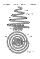
- FIG. 1 shows a basic variation of the inventive device having the general secondary form of a spiral.
- This variation (100) has a conical axis (102) and an outer radius (104).
- this variation of the invention (100) has a generally conical shape and forms a conical envelope. It is produced from a wire thread which is first wound helically into a primary helical spring form and once, so wound, is then wound into a secondary form such as found in FIGS. 1 or 2.
- FIG. 2 shows a view of vasoocclusive coil (100) along the axis (102). Outer diameter (104) is generally selected so that, when unconstrained, it is slightly larger than the vessel into which it is placed.
- the vasoocclusive device (100) may engage the inner lumen of the selected vessel in such a way that axis (102) is generally aligned with the axis of blood vessel tureen.
- the vasoocclusive device having the shape found in FIGS. 1 and 2 may include a small pigtail (106) which further is able to enhance the ability of the device (100) to engage the interior of the vessel wall.
- the length of axis (102) from the apex of the coil (108) to the base of the coil (110) is less than or about the same as the size of the outer diameter (104).
- FIGS. 1 and 2 Central to the embodiment shown in FIGS. 1 and 2 is the use of a primary coil having a variety of regions along its axis with differing flexibilities.
- the physical parameters of the primary coil are varied in such a way that the flexibility of the primary coil is also varied.
- the diameter of the wire (112) and the diameter (114) of the primary coil (116) are maintained at generally constant values throughout the region observed.
- the pitch or spacing between turns is seen to vary substantially in the region shown in FIG. 3.
- the portion of the primary coil (120) shown in FIG. 4 includes a portion (122) of a primary coil (120) having both a small primary diameter (124) and a larger primary diameter (126).
- the flexibility of one end of coil section (120) is different than the flexibility at the other end of coil section (120).
- FIG. 5 is shown a coil section (130) having a region (132) in which both the space between windings of the helical coil is small and the overall diameter of the wire in that section is small, in each case, compared to the larger spacing between coil turns (134) and the diameter of the wire (136) found in coil section (138). In this way, the respective flexibility of the ends of the coil section (130) are quite different.
- the variations of coil stiffness as shown in FIGS. 3, 4, and 5 may be used in producing the coils found in FIGS. 1 and 2 and optionally in producing the other vasoocclusive coils made according to this invention.
- Other methods of changing the flexibility of the wire e.g., by changing composition of the wire along its axis or by annealing regions of the wire are also included.
- the materials making up the vasoocclusive devices found in FIGS. 1-5 and those which are described below are typically metallic. These metallic materials are typically selected from platinum, gold, rhodium, rhenium, palladium, tungsten, and the like, as well as alloys of these metals. Especially preferred for these vasoocclusive devices are alloys of platinum and up to about 15% tungsten. These metals and alloys have significant radioopacity and their alloys may be tailored to accomplish an appropriate flexibility. These materials are also largely biologically compatible.
- the material making up the vasoocclusive coils may be of other suitable biocompatible materials, (e.g., polymers), composites of metals or alloys and polymers, etc. It is only necessary that the device hold its shape upon introduction into the vasoocclusive region and that it be significantly biocompatible.
- Polymeric wire materials are often mixed with a radioopaque material, such as barium sulfate, bismuth trioxide, bismuth carbonate, powdered tungsten, powdered tantalum, or the like, to promote their passive ability to be visualized using fluoroscopy.
- the diameter of the wire typically used in this invention will typically be in the range of 0.0005 and 0.008 inches. Larger diameter wire (e.g., 0.003 to 0.008 inches) may be desired for very specific indications where occlusion is needed at a high volume flow rate site. Such might include repair of an infant's Vein of Galen and treatment of arteriovenous malformations (AVM's). Larger diameter wire would be chosen because of its springiness. Materials with higher innate springiness, e.g., platinum alloys with high tungsten content, would also be suitable for such high flow regions.
- the primary coil diameter (114 in FIG. 3 and 124 and 126 in FIG. 4) will nominally be in the range of 0.008 and 0.075 inches. For most neurovascular indications, a range of 0.010 and 0.018 inches is acceptable. For many peripheral applications or neurological applications where large vessel abnormalities are found(e.g., Vein of Galen malformations or dural fistulae), the primary coil diameter is usually less than about 0.060 inches, preferably 0.018 to 0.038 inches. The axial length of the primary shape will usually fall in the range of 0.5 to 100 centimeters, more usually 2 to 40 centimeters. Depending upon usage and wire diameter, the coil may well have 10 to 200 turns per centimeter. All of the dimensions noted here are provided only as guidelines and are not critical to the statement of the invention. However, only dimensions which are suitable for occluding sites within the human body are included within the scope of this invention.
- the vasoocclusive coil shown in FIGS. 1 and 2 it is desirable to utilize the primary coil variations such as are shown in FIGS. 2, 3, and 4 in such a way that at least a major portion of the first or outer mm of the secondary shape of FIGS. 1 and 2 is stiffer than the remainder of the secondary turns.
- This obviously provides a secondary shape in which the outer region which contacts the vessel lumen is more able to engage the wall of the vessel lumen and maintain both the placement and orientation of the device once it is situated within the site to be occluded.
- the number of rams need not be so limited. It is desirable, as shown in FIGS. 1 and 2, that up to seven or eight rams of secondary shape be attained between the apex and the large end. Any or all of these turns may be relatively stiffer but, as noted above, it is preferred that only the outer turn or largest turn be of enhanced stiffness.
- FIGS. 6 and 7 show, respectively, side views and top views of another variation of the invention.
- the variation (150) shown in FIGS. 6 and 7 comprises two sections: a conical section (152) and a filler section (154).
- the conical section is of the same, generally a spiraling, circular form of decreasing (or increasing) radius secondary coils.
- the filler section (154) extends into the conical region formed by the interior of the conical section (152) It is a generally constant diameter section used to in-fill the conical section (152).
- FIGS. 6 and 7 show the in-filling section (154) to be of a constant diameter and have an axis which is approximately perpendicular to the axis of the conical section (152).
- filler section (154) is not particularly critical. It is placed in the open region within conical section (152) merely to provide extra surfaces with which to begin the formation of embolus after deployment of vasoocclusive device (150).
- the length of filler section (154) may be as much as 50% of the overall diameter of the large end of the conical section (152).
- the shape of filler coil (154) need not be of constant radius but may be of some other form suitable for this device.
- the axis of filler section (154) may be the same as or parallel to the axis of conical section (152).
- FIGS. 8 and 9 show, respectively, a side view and a top view of a variation of the device shown in FIGS. 6 and 7.
- the conical section (162) is skewed so that the axis (164) is generally tangent to the turns of the coil and generally perpendicular to the large coiled end (166).
- the filler section (168) extends from the big turn (166) of the conical section (162) in such as way that it is more of a "pigtail" extending away from the opening formed by the conical section (162).
- Filler section (168) may extend upwardly into the conical section (162) opening, as well.
- the filler section (168) axis is generally parallel to axis (164).
- this variation (160) is generally round.
- FIGS. 10 and 11 show a variation of the device shown in FIGS. 8 and 9. The principal difference is simply that the conical section (172) is elliptical in form.
- FIGS. 12 and 13 show, respectively, side and top views of another variation (180) of the inventive occlusive device in which a generally or abstractly triangular shape is applied to the secondary form.
- the conical section is made up of a number of approximately straight sections which, when viewed along the axis of the cone, form generally a triangular shape.
- the device may be wound in such a way that the straight sections (182) may be aligned to be parallel to another straight section in an adjacent turn.
- This variation is not shown in FIG. 13.
- the variation of FIG. 13 shows secondary coil turns having straight regions (182) which meet other layers at nodes (184). These nodes (184) will, in certain circumstances, provide a more determinate structure to the overall coil assembly (180) after deployment.
- FIGS. 14 and 15 show, respectively, side and top views of another polygonal conical coil assembly in which the straight regions (192) generally form a smoothed square or rectangle.
- the device has a conical aspect to it which, because of the reasonably straight sides (192) results in a rounded pyramid upon deployment of the device.
- each of the devices shown in the above figures may be constructed with a filler section either as shown in FIGS. 6 and 7 or in a pigtail configuration such as is shown in FIGS. 8-11. Further, each of the devices shown in FIGS. 6-15 may be made employing variable stiffness such as may be achieved by varying a physical parameter of the primary coil as indicated in FIGS. 3-5.
- FIGS. 16A, 16B, and 16C depict a common deployment method for the inventive vasoocclusive device as described here. It may be observed that these procedures are not significantly different than those described in Ritchart et al. (U.S. Pat. No. 4,994,069).
- the inventive vasoocclusive device During the period the inventive vasoocclusive device is situated within the constraining tubular member making up the catheter, the vasoocclusive device maintains its primary form, which clearly is generally linear or at least is within the constraining catheter lumen.
- the helically wound tubular member assumes a secondary configuration, different from the first configuration, which secondary configurations have been shown and discussed with relation to the figures above.
- the major difference in the procedure is the propensity of the device as described here to engage the wall of the vessel lumen as it exits the catheter distal tip.
- FIG. 16A shows the distal tip of the catheter (200) which is within the lumen of an artery (202).
- the distal or end section (204) of the coil is shown emerging from the distal dip of the catheter (200).
- the distal end portion (204) is shown beginning to droop towards the wall of the blood vessel (202).
- the end section (204) has proceeded farther out of the catheter distal end (206) and has engaged the wall of the blood vessel (202).
- the end section (204) is along the wall of the vessel (202) and the secondary shape of the vasoocclusive device is beginning to form. As the vasoocclusive device continues to extend from the catheter (206) it will become more conical in shape and will form an occlusive site within vessel (202)
- deployment tips suitable for assisting in deployment of the inventive vasoocclusive device.
- the deployment tips are electrolytically decomposable regions.
- the deployment tips may be mechanical in nature.
- Such connective joints are shown in a variety of patents assigned to Target Therapeutics, Inc., of Fremont, Calif. Such patents include U.S. Pat. No. 5,234,437, to Sepetka; U.S. Pat. No. 5,250,071, to Palermo; U.S. Pat. No.
Abstract
Description
Claims (28)
Priority Applications (5)
| Application Number | Priority Date | Filing Date | Title |
|---|---|---|---|
| US08/625,805 US5649949A (en) | 1996-03-14 | 1996-03-28 | Variable cross-section conical vasoocclusive coils |
| CA002199988A CA2199988C (en) | 1996-03-14 | 1997-03-13 | Variable cross-section conical vasoocclusive coils |
| NO971171A NO971171D0 (en) | 1996-03-28 | 1997-03-13 | Vaso-exclusive coils with variable cross section |
| EP97301701A EP0795300A1 (en) | 1996-03-14 | 1997-03-13 | Variable cross-section conical vasoocclusive coils |
| AU16298/97A AU708924B2 (en) | 1996-03-14 | 1997-03-14 | Variable cross-section conical vasoocclusive coils |
Applications Claiming Priority (2)
| Application Number | Priority Date | Filing Date | Title |
|---|---|---|---|
| US61513096A | 1996-03-14 | 1996-03-14 | |
| US08/625,805 US5649949A (en) | 1996-03-14 | 1996-03-28 | Variable cross-section conical vasoocclusive coils |
Related Parent Applications (1)
| Application Number | Title | Priority Date | Filing Date |
|---|---|---|---|
| US61513096A Continuation | 1996-03-14 | 1996-03-14 |
Publications (1)
| Publication Number | Publication Date |
|---|---|
| US5649949A true US5649949A (en) | 1997-07-22 |
Family
ID=27087420
Family Applications (1)
| Application Number | Title | Priority Date | Filing Date |
|---|---|---|---|
| US08/625,805 Expired - Lifetime US5649949A (en) | 1996-03-14 | 1996-03-28 | Variable cross-section conical vasoocclusive coils |
Country Status (4)
| Country | Link |
|---|---|
| US (1) | US5649949A (en) |
| EP (1) | EP0795300A1 (en) |
| AU (1) | AU708924B2 (en) |
| CA (1) | CA2199988C (en) |
Cited By (178)
| Publication number | Priority date | Publication date | Assignee | Title |
|---|---|---|---|---|
| EP0824010A2 (en) * | 1996-08-15 | 1998-02-18 | Kaneka Medix Corporation | Coiled embolizing material |
| US5725547A (en) * | 1996-01-04 | 1998-03-10 | Chuter; Timothy A. M. | Corrugated stent |
| US5800454A (en) * | 1997-03-17 | 1998-09-01 | Sarcos, Inc. | Catheter deliverable coiled wire thromboginic apparatus and method |
| US5833699A (en) * | 1996-04-10 | 1998-11-10 | Chuter; Timothy A. M. | Extending ribbon stent |
| WO1999009893A1 (en) | 1997-08-29 | 1999-03-04 | Boston Scientific Limited | Anatomically shaped vaso-occlusive device and method of making same |
| US5895351A (en) * | 1998-02-06 | 1999-04-20 | Arthrotek Inc. | Tissue distracting cannula |
| US5911717A (en) * | 1997-03-17 | 1999-06-15 | Precision Vascular Systems, Inc. | Catheter deliverable thrombogenic apparatus and method |
| US5980550A (en) * | 1998-06-18 | 1999-11-09 | Target Therapeutics, Inc. | Water-soluble coating for bioactive vasoocclusive devices |
| US5993482A (en) * | 1996-01-04 | 1999-11-30 | Endovascular Technologies, Inc. | Flat wire stent |
| US6024765A (en) * | 1996-12-30 | 2000-02-15 | Target Therapeutics, Inc. | Vaso-occlusive coil with conical end |
| WO2000035354A1 (en) * | 1998-12-15 | 2000-06-22 | Micrus Corporation | Vasoocclusive coil with variable stiffness |
| US6090125A (en) * | 1995-04-20 | 2000-07-18 | Musc Foundation For Research Development | Anatomically shaped vasoocclusive device and method of making the same |
| US6102932A (en) * | 1998-12-15 | 2000-08-15 | Micrus Corporation | Intravascular device push wire delivery system |
| US6136015A (en) * | 1998-08-25 | 2000-10-24 | Micrus Corporation | Vasoocclusive coil |
| US6149664A (en) * | 1998-08-27 | 2000-11-21 | Micrus Corporation | Shape memory pusher introducer for vasoocclusive devices |
| US6159165A (en) | 1997-12-05 | 2000-12-12 | Micrus Corporation | Three dimensional spherical micro-coils manufactured from radiopaque nickel-titanium microstrand |
| US6165140A (en) | 1998-12-28 | 2000-12-26 | Micrus Corporation | Composite guidewire |
| US6165194A (en) | 1998-07-24 | 2000-12-26 | Micrus Corporation | Intravascular flow modifier and reinforcement device |
| US6168570B1 (en) | 1997-12-05 | 2001-01-02 | Micrus Corporation | Micro-strand cable with enhanced radiopacity |
| US6168615B1 (en) | 1998-05-04 | 2001-01-02 | Micrus Corporation | Method and apparatus for occlusion and reinforcement of aneurysms |
| US6171326B1 (en) | 1998-08-27 | 2001-01-09 | Micrus Corporation | Three dimensional, low friction vasoocclusive coil, and method of manufacture |
| US6187024B1 (en) | 1998-11-10 | 2001-02-13 | Target Therapeutics, Inc. | Bioactive coating for vaso-occlusive devices |
| US6221066B1 (en) | 1999-03-09 | 2001-04-24 | Micrus Corporation | Shape memory segmented detachable coil |
| US6231573B1 (en) * | 1998-04-21 | 2001-05-15 | Medicorp, S.A. | Device for treating aneurysms |
| US6241691B1 (en) | 1997-12-05 | 2001-06-05 | Micrus Corporation | Coated superelastic stent |
| US6280457B1 (en) | 1999-06-04 | 2001-08-28 | Scimed Life Systems, Inc. | Polymer covered vaso-occlusive devices and methods of producing such devices |
| US6293960B1 (en) | 1998-05-22 | 2001-09-25 | Micrus Corporation | Catheter with shape memory polymer distal tip for deployment of therapeutic devices |
| US6296622B1 (en) | 1998-12-21 | 2001-10-02 | Micrus Corporation | Endoluminal device delivery system using axially recovering shape memory material |
| WO2002013708A2 (en) * | 2000-08-11 | 2002-02-21 | Scimed Life Systems, Inc. | Method of making vaso-occlusive coils |
| US6352531B1 (en) | 1999-03-24 | 2002-03-05 | Micrus Corporation | Variable stiffness optical fiber shaft |
| WO2002032325A1 (en) | 2000-10-18 | 2002-04-25 | Scimed Life Systems, Inc. | Non-overlapping spherical three-dimensional vaso-occlusive coil |
| US20020058640A1 (en) * | 1999-07-12 | 2002-05-16 | Scimed Life Systems, Inc. | Liquid based vaso-occlusive compositions |
| WO2002039911A2 (en) | 2000-11-15 | 2002-05-23 | Scimed Life Systems Inc. | Implantable devices with polymeric detachment junction |
| WO2002045596A2 (en) | 2000-12-07 | 2002-06-13 | Scimed Life Systems, Inc. | Light-activated multi-point detachment mechanism |
| US20020107534A1 (en) * | 2000-09-26 | 2002-08-08 | Dean Schaefer | Microcoil vaso-occlusive device with multi-axis secondary configuration |
| US20020128701A1 (en) * | 2000-04-28 | 2002-09-12 | Winters R. Edward | Low profile expandable hoop support device for flexible tubes |
| US6478773B1 (en) | 1998-12-21 | 2002-11-12 | Micrus Corporation | Apparatus for deployment of micro-coil using a catheter |
| US20020173839A1 (en) * | 1998-07-24 | 2002-11-21 | Leopold Eric W. | Intravascular flow modifier and reinforcement device with connected segments |
| US6500149B2 (en) | 1998-08-31 | 2002-12-31 | Deepak Gandhi | Apparatus for deployment of micro-coil using a catheter |
| US20030018356A1 (en) * | 2000-09-26 | 2003-01-23 | Dean Schaefer | Microcoil vaso-occlusive device with multi-axis secondary configuration |
| US6551340B1 (en) | 1998-10-09 | 2003-04-22 | Board Of Regents The University Of Texas System | Vasoocclusion coil device having a core therein |
| US6569179B2 (en) | 1998-11-10 | 2003-05-27 | Scimed Life Systems, Inc. | Bioactive three loop coil |
| US20030105884A1 (en) * | 2001-10-18 | 2003-06-05 | Mitch Upton | System and method for using Web services with an enterprise system |
| US6585758B1 (en) | 1999-11-16 | 2003-07-01 | Scimed Life Systems, Inc. | Multi-section filamentary endoluminal stent |
| WO2003053257A1 (en) * | 2001-12-20 | 2003-07-03 | Scimed Life Systems, Inc. | Vaso-occlusive device with serpentine shape |
| US6605101B1 (en) * | 2000-09-26 | 2003-08-12 | Microvention, Inc. | Microcoil vaso-occlusive device with multi-axis secondary configuration |
| US6610087B1 (en) | 1999-11-16 | 2003-08-26 | Scimed Life Systems, Inc. | Endoluminal stent having a matched stiffness region and/or a stiffness gradient and methods for providing stent kink resistance |
| US20030191521A1 (en) * | 1998-07-24 | 2003-10-09 | Denardo Andrew J. | Intravascular flow modifier and reinforcement device |
| US6638291B1 (en) | 1995-04-20 | 2003-10-28 | Micrus Corporation | Three dimensional, low friction vasoocclusive coil, and method of manufacture |
| US6658288B1 (en) | 2000-05-05 | 2003-12-02 | Endovascular Technologies, Inc. | Apparatus and method for aiding thrombosis through the application of electric potential |
| US20040006362A1 (en) * | 2002-07-02 | 2004-01-08 | Dean Schaefer | Uniaxial multifilar vaso-occlusive device with high stretch resistance and low buckling strength |
| US6719782B1 (en) | 1996-01-04 | 2004-04-13 | Endovascular Technologies, Inc. | Flat wire stent |
| US6723112B2 (en) | 1998-11-10 | 2004-04-20 | Scimed Life Systems, Inc. | Bioactive three loop coil |
| US6729356B1 (en) | 2000-04-27 | 2004-05-04 | Endovascular Technologies, Inc. | Endovascular graft for providing a seal with vasculature |
| US20040093014A1 (en) * | 1998-11-10 | 2004-05-13 | Hanh Ho | Bioactive components for incorporation with vaso-occlusive members |
| US20040153025A1 (en) * | 2003-02-03 | 2004-08-05 | Seifert Paul S. | Systems and methods of de-endothelialization |
| US6790218B2 (en) | 1999-12-23 | 2004-09-14 | Swaminathan Jayaraman | Occlusive coil manufacture and delivery |
| US6835185B2 (en) | 1998-12-21 | 2004-12-28 | Micrus Corporation | Intravascular device deployment mechanism incorporating mechanical detachment |
| US20050033350A1 (en) * | 1996-10-25 | 2005-02-10 | Target Therapeutics, Inc. | Detachable multidiameter vasoocclusive coil |
| US6860893B2 (en) | 1997-08-29 | 2005-03-01 | Boston Scientific Scimed, Inc. | Stable coil designs |
| US20050065545A1 (en) * | 2003-09-23 | 2005-03-24 | Scimed Life Systems, Inc. | External activation of vaso-occlusive implants |
| US20050065501A1 (en) * | 2003-09-23 | 2005-03-24 | Scimed Life Systems, Inc. | Energy activated vaso-occlusive devices |
| US20050187564A1 (en) * | 1999-12-23 | 2005-08-25 | Swaminathan Jayaraman | Occlusive coil manufacturing and delivery |
| US20060074409A1 (en) * | 2004-10-05 | 2006-04-06 | Scimed Life Systems, Inc. | Detachable shaft medical retrieval device and related methods of use |
| US20060079926A1 (en) * | 2004-10-07 | 2006-04-13 | Rupesh Desai | Vasoocclusive coil with biplex windings to improve mechanical properties |
| US20060100661A1 (en) * | 2004-11-09 | 2006-05-11 | Boston Scientific Scimed, Inc. | Vaso-occlusive devices comprising complex-shape proximal portion and smaller diameter distal portion |
| US20060106421A1 (en) * | 2004-11-16 | 2006-05-18 | Clifford Teoh | Expansible neck bridge |
| US20060224177A1 (en) * | 2005-04-01 | 2006-10-05 | Stephanos Finitsis | Thrombus removal system and process |
| US20060241686A1 (en) * | 1995-04-20 | 2006-10-26 | Ferrera David A | Three dimensional, low friction vasoocclusive coil, and method of manufacture |
| US20060241682A1 (en) * | 2003-12-08 | 2006-10-26 | Kurz Daniel R | Intravascular device push wire delivery system |
| US20070083257A1 (en) * | 2005-09-13 | 2007-04-12 | Dharmendra Pal | Aneurysm occlusion device |
| US20070104752A1 (en) * | 2003-12-10 | 2007-05-10 | Lee Jeffrey A | Aneurysm embolization material and device |
| US20070129786A1 (en) * | 2005-10-14 | 2007-06-07 | Bradley Beach | Helical stent |
| US20070144528A1 (en) * | 1995-06-07 | 2007-06-28 | Julian Nikolchev | Contraceptive transcervical fallopian tube occlusion devices and their delivery |
| US20070162108A1 (en) * | 2005-12-13 | 2007-07-12 | Carlson James M | Implantable medical device using palladium |
| US20070255399A1 (en) * | 2005-10-26 | 2007-11-01 | Eliasen Kenneth A | Balloon Mitral Spacer |
| US20070265700A1 (en) * | 2005-10-26 | 2007-11-15 | Eliasen Kenneth A | Safety for Mitral Valve Plug |
| US20080109057A1 (en) * | 2003-12-10 | 2008-05-08 | Calabria Marie F | Multiple point detacher system |
| WO2008106171A1 (en) * | 2007-02-27 | 2008-09-04 | Cook Incorporated | Variable stiffness occluding device |
| US20080288061A1 (en) * | 2007-05-14 | 2008-11-20 | Maurer Christopher W | Solid Construct Mitral Spacer |
| US20080319534A1 (en) * | 2007-06-22 | 2008-12-25 | Medtronic Vascular, Inc. | Stent With Improved Mechanical Properties |
| US20080319532A1 (en) * | 2004-09-22 | 2008-12-25 | Ev3, Inc. | Medical Implant |
| US20080319527A1 (en) * | 2007-06-22 | 2008-12-25 | Lee Jeffrey A | Shaped multi-durometer filler |
| US20090048668A1 (en) * | 2008-06-13 | 2009-02-19 | Cardiosolutions, Inc. | System and Method for Implanting a Heart Implant |
| US20090131849A1 (en) * | 2007-11-15 | 2009-05-21 | Cardiosolutions, Inc. | Heart regurgitation method and apparatus |
| US20090132033A1 (en) * | 2007-11-15 | 2009-05-21 | Cardiosolutions, Inc. | Implant Delivery System and Method |
| WO2009026253A3 (en) * | 2007-08-17 | 2009-05-22 | Micrus Endovascular Corp | A twisted primary coil for vascular therapy |
| US20090227976A1 (en) * | 2008-03-05 | 2009-09-10 | Calabria Marie F | Multiple biocompatible polymeric strand aneurysm embolization system and method |
| US20090240326A1 (en) * | 2005-10-26 | 2009-09-24 | Cardiosolutions | Implant Delivery and Deployment System and Method |
| US20090254112A1 (en) * | 2007-02-07 | 2009-10-08 | Micrus Endovascular Corporation | Winding mandrel for vasoocclusive coils |
| US20090270908A1 (en) * | 2008-04-29 | 2009-10-29 | Cook Incorporated | Device and method for occlusion of fluid flow through a body vessel |
| US7645275B2 (en) | 1999-03-24 | 2010-01-12 | Micrus Corporation | Variable stiffness heating catheter |
| US20100010533A1 (en) * | 2008-07-11 | 2010-01-14 | Cook Incorporated | Variable strength embolization coil |
| US20100022948A1 (en) * | 2008-06-13 | 2010-01-28 | Cardiosolutions | Steerable Catheter and Dilator and System and Method for Implanting a Heart Implant |
| US20100094394A1 (en) * | 2008-10-06 | 2010-04-15 | Bradley Beach | Reconstrainable stent delivery system |
| US7740637B2 (en) | 2000-02-09 | 2010-06-22 | Micrus Endovascular Corporation | Apparatus and method for deployment of a therapeutic device using a catheter |
| US7744583B2 (en) | 2003-02-03 | 2010-06-29 | Boston Scientific Scimed | Systems and methods of de-endothelialization |
| US7803180B2 (en) | 2005-04-04 | 2010-09-28 | Flexible Stenting Solutions, Inc. | Flexible stent |
| WO2010092174A3 (en) * | 2009-02-16 | 2010-10-21 | Justus-Liebig-Universität Giessen | Implant |
| US20100286760A1 (en) * | 2009-04-24 | 2010-11-11 | Bradley Beach | Flexible devices |
| US20100324668A1 (en) * | 2005-10-26 | 2010-12-23 | Cardiosolutions, Inc. | Mitral Spacer |
| US8007509B2 (en) * | 2005-10-12 | 2011-08-30 | Boston Scientific Scimed, Inc. | Coil assemblies, components and methods |
| US20110230909A1 (en) * | 2005-04-01 | 2011-09-22 | Nexgen Medical Systems, Inc. | Thrombus removal system and process |
| US20110245861A1 (en) * | 2010-04-05 | 2011-10-06 | Boston Scientific Scimed, Inc. | Vaso-occlusive devices |
| US8328860B2 (en) | 2007-03-13 | 2012-12-11 | Covidien Lp | Implant including a coil and a stretch-resistant member |
| KR101250448B1 (en) | 2010-12-27 | 2013-04-08 | 권오기 | Embolus forming in-vivo indwelling-coil and the makigng methods for Embolus forming in-vivo indwelling coil |
| US20130103074A1 (en) * | 2007-12-11 | 2013-04-25 | Cornell University | Method and apparatus for restricting flow through an opening in the side wall of a body lumen, and/or for reinforcing a weakness in the side wall of a body lumen, while still maintaining substantially normal flow through the body lumen |
| US8500794B2 (en) | 2007-08-02 | 2013-08-06 | Flexible Stenting Solutions, Inc. | Flexible stent |
| US20130238012A1 (en) * | 2004-12-01 | 2013-09-12 | Christopher J. Elliott | Embolic coils |
| EP2520233A3 (en) * | 2009-04-02 | 2013-10-16 | Endoshape, Inc. | Vascular occlusion devices |
| US8613282B2 (en) | 1997-09-24 | 2013-12-24 | Conceptus, Inc. | Occlusion devices and methods |
| US8777978B2 (en) | 2006-04-17 | 2014-07-15 | Covidien Lp | System and method for mechanically positioning intravascular implants |
| US8777979B2 (en) | 2006-04-17 | 2014-07-15 | Covidien Lp | System and method for mechanically positioning intravascular implants |
| WO2013109894A3 (en) * | 2012-01-20 | 2014-08-07 | Covidien Lp | Aneurysm treatment coils |
| US8801747B2 (en) | 2007-03-13 | 2014-08-12 | Covidien Lp | Implant, a mandrel, and a method of forming an implant |
| US8828051B2 (en) | 2010-07-02 | 2014-09-09 | Pfm Medical Ag | Left atrial appendage occlusion device |
| US8864811B2 (en) | 2010-06-08 | 2014-10-21 | Veniti, Inc. | Bi-directional stent delivery system |
| US8888844B2 (en) | 2005-10-26 | 2014-11-18 | Cardiosolutions, Inc. | Heart valve implant |
| US20150032145A1 (en) * | 2007-12-11 | 2015-01-29 | Cornell University | Method and apparatus for restricting flow through an opening in the side wall of a body lumen, and/or for reinforcing a weakness in the side wall of a body lumen, while still maintaining substantially normal flow through the body lumen |
| US8956475B2 (en) | 2007-12-11 | 2015-02-17 | Howard Riina | Method and apparatus for restricting flow through an opening in the side wall of a body lumen, and/or for reinforcing a weakness in the side wall of a body lumen, while still maintaining substantially normal flow through the body lumen |
| US20150114401A1 (en) * | 2012-04-24 | 2015-04-30 | Ruben Van Der Vleuten | Applicator for delivering an occluding compound in a fallopian tube |
| WO2015100297A1 (en) * | 2013-12-26 | 2015-07-02 | Stryker Corporation | Vaso-occlusive coil with bending sections |
| US20150238198A1 (en) * | 2014-02-27 | 2015-08-27 | Incumedx, Inc. | Embolic framing microcoils |
| US9119948B2 (en) | 2013-02-20 | 2015-09-01 | Covidien Lp | Occlusive implants for hollow anatomical structures, delivery systems, and related methods |
| US9131941B2 (en) | 2011-06-17 | 2015-09-15 | Curaseal Inc. | Fistula treatment devices and methods |
| US20150289881A1 (en) * | 2012-06-29 | 2015-10-15 | Kaneka Corporation | Method for producing in-vivo indwelling member |
| US9174020B2 (en) | 2013-05-08 | 2015-11-03 | Embolx, Inc. | Device and methods for transvascular tumor embolization with integrated flow regulation |
| US9198665B2 (en) | 2004-09-22 | 2015-12-01 | Covidien Lp | Micro-spiral implantation device |
| US9211116B2 (en) | 2011-06-16 | 2015-12-15 | Curaseal Inc. | Fistula treatment devices and related methods |
| US9233014B2 (en) | 2010-09-24 | 2016-01-12 | Veniti, Inc. | Stent with support braces |
| US9232998B2 (en) | 2013-03-15 | 2016-01-12 | Cardiosolutions Inc. | Trans-apical implant systems, implants and methods |
| US9289297B2 (en) | 2013-03-15 | 2016-03-22 | Cardiosolutions, Inc. | Mitral valve spacer and system and method for implanting the same |
| WO2016044188A1 (en) * | 2014-09-15 | 2016-03-24 | Jones Donald K | Intralumenal occlusion devices having improved properties |
| US9301864B2 (en) | 2010-06-08 | 2016-04-05 | Veniti, Inc. | Bi-directional stent delivery system |
| US9358140B1 (en) | 2009-11-18 | 2016-06-07 | Aneuclose Llc | Stent with outer member to embolize an aneurysm |
| US9545305B2 (en) | 2013-06-14 | 2017-01-17 | Cardiosolutions, Inc. | Mitral valve spacer and system and method for implanting the same |
| US9550046B1 (en) | 2016-02-16 | 2017-01-24 | Embolx, Inc. | Balloon catheter and methods of fabrication and use |
| US20170049357A1 (en) * | 2011-12-30 | 2017-02-23 | Mediguide Ltd. | Roll detection and six degrees of freedom sensor assembly |
| US9579104B2 (en) | 2011-11-30 | 2017-02-28 | Covidien Lp | Positioning and detaching implants |
| US9592068B2 (en) | 2013-03-15 | 2017-03-14 | Insera Therapeutics, Inc. | Free end vascular treatment systems |
| US9649211B2 (en) | 2009-11-04 | 2017-05-16 | Confluent Medical Technologies, Inc. | Alternating circumferential bridge stent design and methods for use thereof |
| US9687245B2 (en) | 2012-03-23 | 2017-06-27 | Covidien Lp | Occlusive devices and methods of use |
| WO2017117284A1 (en) | 2015-12-30 | 2017-07-06 | Stryker Corporation | Embolic devices and methods of manufacturing same |
| US9713475B2 (en) | 2014-04-18 | 2017-07-25 | Covidien Lp | Embolic medical devices |
| WO2017132415A1 (en) * | 2016-01-29 | 2017-08-03 | Cable Coilers Llc | Coiling device |
| US9750524B2 (en) | 2013-03-15 | 2017-09-05 | Insera Therapeutics, Inc. | Shape-set textile structure based mechanical thrombectomy systems |
| US9833251B2 (en) | 2013-03-15 | 2017-12-05 | Insera Therapeutics, Inc. | Variably bulbous vascular treatment devices |
| US9844383B2 (en) | 2013-05-08 | 2017-12-19 | Embolx, Inc. | Devices and methods for low pressure tumor embolization |
| US9901435B2 (en) | 2013-03-15 | 2018-02-27 | Insera Therapeutics, Inc. | Longitudinally variable vascular treatment devices |
| US20180104040A1 (en) * | 2016-10-14 | 2018-04-19 | Microvention, Inc. | Embolic Coils |
| WO2018073830A2 (en) | 2016-10-21 | 2018-04-26 | Javelin Medical Ltd. | Systems, methods and devices for embolic protection |
| US20180125498A1 (en) * | 2015-04-24 | 2018-05-10 | Pfm Medical Ag | A medical implant for closure of a defect aperture, a vessel, an organ path or another aperture in a human or animal body |
| US9993235B2 (en) | 2008-09-04 | 2018-06-12 | Curaseal Inc. | Enteric fistula treatment devices |
| US10028747B2 (en) | 2008-05-01 | 2018-07-24 | Aneuclose Llc | Coils with a series of proximally-and-distally-connected loops for occluding a cerebral aneurysm |
| US10092427B2 (en) | 2009-11-04 | 2018-10-09 | Confluent Medical Technologies, Inc. | Alternating circumferential bridge stent design and methods for use thereof |
| US10201351B2 (en) | 2011-09-30 | 2019-02-12 | Endoshape, Inc. | Continuous embolic coil and methods and devices for delivery of the same |
| US10307168B2 (en) | 2015-08-07 | 2019-06-04 | Terumo Corporation | Complex coil and manufacturing techniques |
| US10350382B1 (en) | 2018-06-08 | 2019-07-16 | Embolx, Inc. | High torque catheter and methods of manufacture |
| US10390926B2 (en) | 2013-07-29 | 2019-08-27 | Insera Therapeutics, Inc. | Aspiration devices and methods |
| EP3622902A1 (en) * | 2018-09-12 | 2020-03-18 | Cook Medical Technologies LLC | Embolization coil with end coil integrated within main coil |
| US10595875B2 (en) | 2014-12-31 | 2020-03-24 | Endostream Medical Ltd. | Device for restricting blood flow to aneurysms |
| US10603043B2 (en) | 2012-01-17 | 2020-03-31 | Endoshape, Inc. | Occlusion device for a vascular or biological lumen |
| WO2020139544A2 (en) | 2018-12-27 | 2020-07-02 | Stryker Corporation | Shape adaptable multi-layered intra-saccular flow reduction device and methods of manufacturing same |
| US10716573B2 (en) | 2008-05-01 | 2020-07-21 | Aneuclose | Janjua aneurysm net with a resilient neck-bridging portion for occluding a cerebral aneurysm |
| WO2020136643A3 (en) * | 2018-12-26 | 2020-08-06 | Endostream Medical Ltd. | Devices for treating vascular malformations |
| US10786378B2 (en) * | 2013-03-13 | 2020-09-29 | DePuy Synthes Products, Inc. | Capture tube mechanism for delivering and releasing a stent |
| US10869673B2 (en) * | 2015-02-05 | 2020-12-22 | Boston Scientific Scimed, Inc. | Embolic coil with kick-in tail |
| US10905432B2 (en) * | 2018-08-22 | 2021-02-02 | Covidien Lp | Aneurysm treatment coils and associated systems and methods of use |
| US10912569B2 (en) * | 2018-08-22 | 2021-02-09 | Covidien Lp | Aneurysm treatment coils and associated systems and methods of use |
| US10925708B2 (en) | 2012-05-31 | 2021-02-23 | Javelin Medical Ltd. | Monofilament implants and systems for delivery thereof |
| US10966728B2 (en) | 2016-06-21 | 2021-04-06 | Endostream Medical Ltd. | Medical device for treating vascular malformations |
| US20210137526A1 (en) * | 2019-11-11 | 2021-05-13 | Stryker Corporation | Embolic devices for occluding body lumens |
| US11207170B2 (en) | 2012-05-31 | 2021-12-28 | Javelin Medical Ltd. | Systems, methods and devices for embolic protection |
| US11399840B2 (en) | 2019-08-13 | 2022-08-02 | Covidien Lp | Implantable embolization device |
| US11464948B2 (en) | 2016-02-16 | 2022-10-11 | Embolx, Inc. | Balloon catheters and methods of manufacture and use |
| US11484397B2 (en) | 2013-12-06 | 2022-11-01 | Javelin Medical Ltd. | Systems and methods for implant delivery |
| WO2023086738A1 (en) * | 2021-11-11 | 2023-05-19 | Stryker Corporation | Vaso-occlusive devices and methods for making and using same |
| US11812970B2 (en) | 2019-01-17 | 2023-11-14 | Endostream Medical Ltd. | Vascular-malformation implant system |
Citations (20)
| Publication number | Priority date | Publication date | Assignee | Title |
|---|---|---|---|---|
| US4619246A (en) * | 1984-05-23 | 1986-10-28 | William Cook, Europe A/S | Collapsible filter basket |
| US4638803A (en) * | 1982-09-30 | 1987-01-27 | Rand Robert W | Medical apparatus for inducing scar tissue formation in a body |
| US4994069A (en) * | 1988-11-02 | 1991-02-19 | Target Therapeutics | Vaso-occlusion coil and method |
| US5122136A (en) * | 1990-03-13 | 1992-06-16 | The Regents Of The University Of California | Endovascular electrolytically detachable guidewire tip for the electroformation of thrombus in arteries, veins, aneurysms, vascular malformations and arteriovenous fistulas |
| WO1992014408A1 (en) * | 1991-02-15 | 1992-09-03 | Malte Neuss | Spiral implant for bodily ducts |
| JPH04312454A (en) * | 1991-04-11 | 1992-11-04 | Olympus Optical Co Ltd | Organism pipe clogging tool |
| US5217484A (en) * | 1991-06-07 | 1993-06-08 | Marks Michael P | Retractable-wire catheter device and method |
| US5234437A (en) * | 1991-12-12 | 1993-08-10 | Target Therapeutics, Inc. | Detachable pusher-vasoocclusion coil assembly with threaded coupling |
| US5250071A (en) * | 1992-09-22 | 1993-10-05 | Target Therapeutics, Inc. | Detachable embolic coil assembly using interlocking clasps and method of use |
| US5261916A (en) * | 1991-12-12 | 1993-11-16 | Target Therapeutics | Detachable pusher-vasoocclusive coil assembly with interlocking ball and keyway coupling |
| US5304195A (en) * | 1991-12-12 | 1994-04-19 | Target Therapeutics, Inc. | Detachable pusher-vasoocclusive coil assembly with interlocking coupling |
| US5312415A (en) * | 1992-09-22 | 1994-05-17 | Target Therapeutics, Inc. | Assembly for placement of embolic coils using frictional placement |
| US5334210A (en) * | 1993-04-09 | 1994-08-02 | Cook Incorporated | Vascular occlusion assembly |
| US5350397A (en) * | 1992-11-13 | 1994-09-27 | Target Therapeutics, Inc. | Axially detachable embolic coil assembly |
| US5354295A (en) * | 1990-03-13 | 1994-10-11 | Target Therapeutics, Inc. | In an endovascular electrolytically detachable wire and tip for the formation of thrombus in arteries, veins, aneurysms, vascular malformations and arteriovenous fistulas |
| US5413586A (en) * | 1991-03-14 | 1995-05-09 | Ethnor | Anti-pulmonary embolism filter and corresponding presentation and fitting kit |
| US5417708A (en) * | 1994-03-09 | 1995-05-23 | Cook Incorporated | Intravascular treatment system and percutaneous release mechanism therefor |
| US5423777A (en) * | 1993-10-27 | 1995-06-13 | Tajiri; Akira | Punctum plug |
| US5443478A (en) * | 1992-09-02 | 1995-08-22 | Board Of Regents, The University Of Texas System | Multi-element intravascular occlusion device |
| WO1995025480A1 (en) * | 1994-03-18 | 1995-09-28 | Cook Incorporated | Helical embolization coil |
Family Cites Families (2)
| Publication number | Priority date | Publication date | Assignee | Title |
|---|---|---|---|---|
| US5766160A (en) * | 1995-06-06 | 1998-06-16 | Target Therapeutics, Inc. | Variable stiffness coils |
| NO962336L (en) * | 1995-06-06 | 1996-12-09 | Target Therapeutics Inc | Vaso-occlusive spiral |
-
1996
- 1996-03-28 US US08/625,805 patent/US5649949A/en not_active Expired - Lifetime
-
1997
- 1997-03-13 CA CA002199988A patent/CA2199988C/en not_active Expired - Fee Related
- 1997-03-13 EP EP97301701A patent/EP0795300A1/en not_active Withdrawn
- 1997-03-14 AU AU16298/97A patent/AU708924B2/en not_active Ceased
Patent Citations (20)
| Publication number | Priority date | Publication date | Assignee | Title |
|---|---|---|---|---|
| US4638803A (en) * | 1982-09-30 | 1987-01-27 | Rand Robert W | Medical apparatus for inducing scar tissue formation in a body |
| US4619246A (en) * | 1984-05-23 | 1986-10-28 | William Cook, Europe A/S | Collapsible filter basket |
| US4994069A (en) * | 1988-11-02 | 1991-02-19 | Target Therapeutics | Vaso-occlusion coil and method |
| US5354295A (en) * | 1990-03-13 | 1994-10-11 | Target Therapeutics, Inc. | In an endovascular electrolytically detachable wire and tip for the formation of thrombus in arteries, veins, aneurysms, vascular malformations and arteriovenous fistulas |
| US5122136A (en) * | 1990-03-13 | 1992-06-16 | The Regents Of The University Of California | Endovascular electrolytically detachable guidewire tip for the electroformation of thrombus in arteries, veins, aneurysms, vascular malformations and arteriovenous fistulas |
| WO1992014408A1 (en) * | 1991-02-15 | 1992-09-03 | Malte Neuss | Spiral implant for bodily ducts |
| US5413586A (en) * | 1991-03-14 | 1995-05-09 | Ethnor | Anti-pulmonary embolism filter and corresponding presentation and fitting kit |
| JPH04312454A (en) * | 1991-04-11 | 1992-11-04 | Olympus Optical Co Ltd | Organism pipe clogging tool |
| US5217484A (en) * | 1991-06-07 | 1993-06-08 | Marks Michael P | Retractable-wire catheter device and method |
| US5261916A (en) * | 1991-12-12 | 1993-11-16 | Target Therapeutics | Detachable pusher-vasoocclusive coil assembly with interlocking ball and keyway coupling |
| US5304195A (en) * | 1991-12-12 | 1994-04-19 | Target Therapeutics, Inc. | Detachable pusher-vasoocclusive coil assembly with interlocking coupling |
| US5234437A (en) * | 1991-12-12 | 1993-08-10 | Target Therapeutics, Inc. | Detachable pusher-vasoocclusion coil assembly with threaded coupling |
| US5443478A (en) * | 1992-09-02 | 1995-08-22 | Board Of Regents, The University Of Texas System | Multi-element intravascular occlusion device |
| US5250071A (en) * | 1992-09-22 | 1993-10-05 | Target Therapeutics, Inc. | Detachable embolic coil assembly using interlocking clasps and method of use |
| US5312415A (en) * | 1992-09-22 | 1994-05-17 | Target Therapeutics, Inc. | Assembly for placement of embolic coils using frictional placement |
| US5350397A (en) * | 1992-11-13 | 1994-09-27 | Target Therapeutics, Inc. | Axially detachable embolic coil assembly |
| US5334210A (en) * | 1993-04-09 | 1994-08-02 | Cook Incorporated | Vascular occlusion assembly |
| US5423777A (en) * | 1993-10-27 | 1995-06-13 | Tajiri; Akira | Punctum plug |
| US5417708A (en) * | 1994-03-09 | 1995-05-23 | Cook Incorporated | Intravascular treatment system and percutaneous release mechanism therefor |
| WO1995025480A1 (en) * | 1994-03-18 | 1995-09-28 | Cook Incorporated | Helical embolization coil |
Cited By (351)
| Publication number | Priority date | Publication date | Assignee | Title |
|---|---|---|---|---|
| US6638291B1 (en) | 1995-04-20 | 2003-10-28 | Micrus Corporation | Three dimensional, low friction vasoocclusive coil, and method of manufacture |
| US20060241686A1 (en) * | 1995-04-20 | 2006-10-26 | Ferrera David A | Three dimensional, low friction vasoocclusive coil, and method of manufacture |
| US8790363B2 (en) | 1995-04-20 | 2014-07-29 | DePuy Synthes Products, LLC | Three dimensional, low friction vasoocclusive coil, and method of manufacture |
| US6090125A (en) * | 1995-04-20 | 2000-07-18 | Musc Foundation For Research Development | Anatomically shaped vasoocclusive device and method of making the same |
| US8733361B2 (en) | 1995-06-07 | 2014-05-27 | Bayer Essure Inc. | Occlusion devices and methods |
| US20070144528A1 (en) * | 1995-06-07 | 2007-06-28 | Julian Nikolchev | Contraceptive transcervical fallopian tube occlusion devices and their delivery |
| US5725547A (en) * | 1996-01-04 | 1998-03-10 | Chuter; Timothy A. M. | Corrugated stent |
| US6454795B1 (en) | 1996-01-04 | 2002-09-24 | Endovascular Technologies, Inc. | High expansion ratio stent |
| US6719782B1 (en) | 1996-01-04 | 2004-04-13 | Endovascular Technologies, Inc. | Flat wire stent |
| US5993482A (en) * | 1996-01-04 | 1999-11-30 | Endovascular Technologies, Inc. | Flat wire stent |
| US5833699A (en) * | 1996-04-10 | 1998-11-10 | Chuter; Timothy A. M. | Extending ribbon stent |
| EP0824010A2 (en) * | 1996-08-15 | 1998-02-18 | Kaneka Medix Corporation | Coiled embolizing material |
| US5891058A (en) * | 1996-08-15 | 1999-04-06 | Kaneka Medix Corporation | Coiled embolizing material |
| EP0824010A3 (en) * | 1996-08-15 | 1998-02-25 | Kaneka Medix Corporation | Coiled embolizing material |
| US20050033350A1 (en) * | 1996-10-25 | 2005-02-10 | Target Therapeutics, Inc. | Detachable multidiameter vasoocclusive coil |
| US6984240B1 (en) * | 1996-10-25 | 2006-01-10 | Target Therapeutics, Inc. | Detachable multidiameter vasoocclusive coil |
| US6024765A (en) * | 1996-12-30 | 2000-02-15 | Target Therapeutics, Inc. | Vaso-occlusive coil with conical end |
| US6660020B2 (en) * | 1996-12-30 | 2003-12-09 | Target Therapeutics, Inc. | Vaso-occlusive coil with conical end |
| US5911717A (en) * | 1997-03-17 | 1999-06-15 | Precision Vascular Systems, Inc. | Catheter deliverable thrombogenic apparatus and method |
| US5800454A (en) * | 1997-03-17 | 1998-09-01 | Sarcos, Inc. | Catheter deliverable coiled wire thromboginic apparatus and method |
| JP2007289719A (en) * | 1997-08-29 | 2007-11-08 | Boston Scientific Ltd | Vascular occlusion device which is anatomically molded |
| US6322576B1 (en) * | 1997-08-29 | 2001-11-27 | Target Therapeutics, Inc. | Stable coil designs |
| WO1999009893A1 (en) | 1997-08-29 | 1999-03-04 | Boston Scientific Limited | Anatomically shaped vaso-occlusive device and method of making same |
| US6860893B2 (en) | 1997-08-29 | 2005-03-01 | Boston Scientific Scimed, Inc. | Stable coil designs |
| US8733360B2 (en) | 1997-09-24 | 2014-05-27 | Bayer Essure Inc. | Occlusion devices and methods |
| US8613282B2 (en) | 1997-09-24 | 2013-12-24 | Conceptus, Inc. | Occlusion devices and methods |
| US7070608B2 (en) | 1997-12-05 | 2006-07-04 | Micrus Corporation | Vasoocclusive coil |
| US6168570B1 (en) | 1997-12-05 | 2001-01-02 | Micrus Corporation | Micro-strand cable with enhanced radiopacity |
| US6241691B1 (en) | 1997-12-05 | 2001-06-05 | Micrus Corporation | Coated superelastic stent |
| US6159165A (en) | 1997-12-05 | 2000-12-12 | Micrus Corporation | Three dimensional spherical micro-coils manufactured from radiopaque nickel-titanium microstrand |
| US6497671B2 (en) | 1997-12-05 | 2002-12-24 | Micrus Corporation | Coated superelastic stent |
| US6475169B2 (en) | 1997-12-05 | 2002-11-05 | Micrus Corporation | Micro-strand cable with enhanced radiopacity |
| US6616617B1 (en) | 1997-12-05 | 2003-09-09 | Micrus Corporation | Vasoocclusive device for treatment of aneurysms |
| US5895351A (en) * | 1998-02-06 | 1999-04-20 | Arthrotek Inc. | Tissue distracting cannula |
| US6231573B1 (en) * | 1998-04-21 | 2001-05-15 | Medicorp, S.A. | Device for treating aneurysms |
| US6168615B1 (en) | 1998-05-04 | 2001-01-02 | Micrus Corporation | Method and apparatus for occlusion and reinforcement of aneurysms |
| USRE42758E1 (en) | 1998-05-04 | 2011-09-27 | Micrus Corporation | Expandable curvilinear strut arrangement for deployment with a catheter to repair an aneurysm |
| US6293960B1 (en) | 1998-05-22 | 2001-09-25 | Micrus Corporation | Catheter with shape memory polymer distal tip for deployment of therapeutic devices |
| US5980550A (en) * | 1998-06-18 | 1999-11-09 | Target Therapeutics, Inc. | Water-soluble coating for bioactive vasoocclusive devices |
| US6299627B1 (en) | 1998-06-18 | 2001-10-09 | Target Therapeutics, Inc. | Water-soluble coating for bioactive vasoocclusive devices |
| WO1999065401A1 (en) | 1998-06-18 | 1999-12-23 | Scimed Life Systems, Inc. | Water-soluble coating for bioactive vaso-occlusive devices |
| US20020173839A1 (en) * | 1998-07-24 | 2002-11-21 | Leopold Eric W. | Intravascular flow modifier and reinforcement device with connected segments |
| US6656218B1 (en) | 1998-07-24 | 2003-12-02 | Micrus Corporation | Intravascular flow modifier and reinforcement device |
| US20030191521A1 (en) * | 1998-07-24 | 2003-10-09 | Denardo Andrew J. | Intravascular flow modifier and reinforcement device |
| US6416541B2 (en) | 1998-07-24 | 2002-07-09 | Micrus Corporation | Intravascular flow modifier and reinforcement device |
| US6165194A (en) | 1998-07-24 | 2000-12-26 | Micrus Corporation | Intravascular flow modifier and reinforcement device |
| US6136015A (en) * | 1998-08-25 | 2000-10-24 | Micrus Corporation | Vasoocclusive coil |
| US6306153B1 (en) | 1998-08-25 | 2001-10-23 | Micrus Corporation | Vasoocclusive coil |
| US6171326B1 (en) | 1998-08-27 | 2001-01-09 | Micrus Corporation | Three dimensional, low friction vasoocclusive coil, and method of manufacture |
| US6149664A (en) * | 1998-08-27 | 2000-11-21 | Micrus Corporation | Shape memory pusher introducer for vasoocclusive devices |
| US6500149B2 (en) | 1998-08-31 | 2002-12-31 | Deepak Gandhi | Apparatus for deployment of micro-coil using a catheter |
| US20030216772A1 (en) * | 1998-10-09 | 2003-11-20 | Board Of Regents, University Of Texas System | Vasoocclusion coil device having a core therein |
| US6551340B1 (en) | 1998-10-09 | 2003-04-22 | Board Of Regents The University Of Texas System | Vasoocclusion coil device having a core therein |
| US20040093014A1 (en) * | 1998-11-10 | 2004-05-13 | Hanh Ho | Bioactive components for incorporation with vaso-occlusive members |
| US6231590B1 (en) | 1998-11-10 | 2001-05-15 | Scimed Life Systems, Inc. | Bioactive coating for vaso-occlusive devices |
| US8016852B2 (en) | 1998-11-10 | 2011-09-13 | Stryker Corporation | Bioactive components for incorporation with vaso-occlusive members |
| US6187024B1 (en) | 1998-11-10 | 2001-02-13 | Target Therapeutics, Inc. | Bioactive coating for vaso-occlusive devices |
| US6723112B2 (en) | 1998-11-10 | 2004-04-20 | Scimed Life Systems, Inc. | Bioactive three loop coil |
| US6569179B2 (en) | 1998-11-10 | 2003-05-27 | Scimed Life Systems, Inc. | Bioactive three loop coil |
| WO2000035354A1 (en) * | 1998-12-15 | 2000-06-22 | Micrus Corporation | Vasoocclusive coil with variable stiffness |
| US6656201B2 (en) | 1998-12-15 | 2003-12-02 | Micrus Corporation | Variable stiffness coil for vasoocclusive devices |
| US6102932A (en) * | 1998-12-15 | 2000-08-15 | Micrus Corporation | Intravascular device push wire delivery system |
| US6319267B1 (en) | 1998-12-15 | 2001-11-20 | Micrus Corporation | Intravascular device push wire delivery system |
| US6383204B1 (en) | 1998-12-15 | 2002-05-07 | Micrus Corporation | Variable stiffness coil for vasoocclusive devices |
| US6872218B2 (en) | 1998-12-15 | 2005-03-29 | Micrus Corporation | Variable stiffness coil for vasoocclusive devices |
| US7147618B2 (en) | 1998-12-15 | 2006-12-12 | Micrus Endovascular Corporation | Intravascular device push wire delivery system |
| US6679903B2 (en) | 1998-12-15 | 2004-01-20 | Micrus Corporation | Intravascular device push wire delivery system |
| US20040122502A1 (en) * | 1998-12-15 | 2004-06-24 | Kurz Daniel R. | Intravascular device push wire delivery system |
| US6835185B2 (en) | 1998-12-21 | 2004-12-28 | Micrus Corporation | Intravascular device deployment mechanism incorporating mechanical detachment |
| US6296622B1 (en) | 1998-12-21 | 2001-10-02 | Micrus Corporation | Endoluminal device delivery system using axially recovering shape memory material |
| US9622754B2 (en) | 1998-12-21 | 2017-04-18 | DePuy Synthes Products, Inc. | Intravascular device deployment mechanism incorporating mechanical detachment |
| US6478773B1 (en) | 1998-12-21 | 2002-11-12 | Micrus Corporation | Apparatus for deployment of micro-coil using a catheter |
| US20050113863A1 (en) * | 1998-12-21 | 2005-05-26 | Kamal Ramzipoor | Intravascular device deployment mechanism incorporating mechanical detachment |
| US6165140A (en) | 1998-12-28 | 2000-12-26 | Micrus Corporation | Composite guidewire |
| US6595932B2 (en) | 1998-12-28 | 2003-07-22 | Micrus Corporation | Composite guidewire |
| US6432066B1 (en) | 1998-12-28 | 2002-08-13 | Micrus Corporation | Composite guidewire |
| US6221066B1 (en) | 1999-03-09 | 2001-04-24 | Micrus Corporation | Shape memory segmented detachable coil |
| US6551305B2 (en) | 1999-03-09 | 2003-04-22 | Micrus Corporation | Shape memory segmented detachable coil |
| US8282677B2 (en) | 1999-03-24 | 2012-10-09 | Micrus Corporation | Variable stiffness heating catheter |
| US7645275B2 (en) | 1999-03-24 | 2010-01-12 | Micrus Corporation | Variable stiffness heating catheter |
| US6352531B1 (en) | 1999-03-24 | 2002-03-05 | Micrus Corporation | Variable stiffness optical fiber shaft |
| US20100174301A1 (en) * | 1999-06-04 | 2010-07-08 | Boston Scientific Scimed, Inc. | Polymer covered vaso-occlusive devices and methods of producing such devices |
| US6280457B1 (en) | 1999-06-04 | 2001-08-28 | Scimed Life Systems, Inc. | Polymer covered vaso-occlusive devices and methods of producing such devices |
| US20050192621A1 (en) * | 1999-06-04 | 2005-09-01 | Scimed Life Systems, Inc. | Polymer covered vaso-occlusive devices and methods of producing such devices |
| US20020128671A1 (en) * | 1999-06-04 | 2002-09-12 | Scimed Life Systems, Inc. | Polymer covered vaso-occlusive devices and methods of producing such devices |
| US8172862B2 (en) | 1999-06-04 | 2012-05-08 | Stryker Corporation | Polymer covered vaso-occlusive devices and methods of producing such devices |
| US7695484B2 (en) | 1999-06-04 | 2010-04-13 | Boston Scientific Scimed, Inc. | Polymer covered vaso-occlusive devices and methods of producing such devices |
| US20020058640A1 (en) * | 1999-07-12 | 2002-05-16 | Scimed Life Systems, Inc. | Liquid based vaso-occlusive compositions |
| US7670367B1 (en) | 1999-11-16 | 2010-03-02 | Boston Scientific Scimed, Inc. | Multi-section filamentary endoluminal stent |
| US6610087B1 (en) | 1999-11-16 | 2003-08-26 | Scimed Life Systems, Inc. | Endoluminal stent having a matched stiffness region and/or a stiffness gradient and methods for providing stent kink resistance |
| US7722664B2 (en) | 1999-11-16 | 2010-05-25 | Boston Scientific Scimed, Inc. | Endoluminal stent having a matched stiffness region and/or a stiffness gradient |
| US6585758B1 (en) | 1999-11-16 | 2003-07-01 | Scimed Life Systems, Inc. | Multi-section filamentary endoluminal stent |
| US20040106981A1 (en) * | 1999-11-16 | 2004-06-03 | Zarbatany David J. | Endoluminal stent having a matched stiffness region and/or a stiffness gradient and methods for providing stent kink resistance |
| US7160319B2 (en) | 1999-11-16 | 2007-01-09 | Scimed Life Systems, Inc. | Multi-section filamentary endoluminal stent |
| US20030149473A1 (en) * | 1999-11-16 | 2003-08-07 | Chouinard Paul F. | Multi-section filamentary endoluminal stent |
| US7214241B2 (en) | 1999-11-16 | 2007-05-08 | Boston Scientific Scimed, Inc. | Endoluminal stent having a matched stiffness region and/or a stiffness gradient and methods for providing stent kink resistance |
| US20050187564A1 (en) * | 1999-12-23 | 2005-08-25 | Swaminathan Jayaraman | Occlusive coil manufacturing and delivery |
| US6790218B2 (en) | 1999-12-23 | 2004-09-14 | Swaminathan Jayaraman | Occlusive coil manufacture and delivery |
| US20050038460A1 (en) * | 1999-12-23 | 2005-02-17 | Swaminathan Jayaraman | Occlusive coil manufacture and delivery |
| US7780680B2 (en) | 2000-02-09 | 2010-08-24 | Micrus Corporation | Apparatus for deployment of micro-coil using a catheter |
| US7972342B2 (en) | 2000-02-09 | 2011-07-05 | Micrus Corporation | Apparatus for deployment of micro-coil using a catheter |
| US7776054B2 (en) | 2000-02-09 | 2010-08-17 | Micrus Corporation | Apparatus for deployment of micro-coil using a catheter |
| US8652163B2 (en) | 2000-02-09 | 2014-02-18 | DePuy Synthes Products, LLC | Apparatus and method for deployment of a therapeutic device using a catheter |
| US8100918B2 (en) | 2000-02-09 | 2012-01-24 | Micrus Corporation | Apparatus for deployment of micro-coil using a catheter |
| US8728142B2 (en) | 2000-02-09 | 2014-05-20 | DePuy Synthes Products, LLC | Apparatus for deployment of micro-coil using a catheter |
| US8298256B2 (en) | 2000-02-09 | 2012-10-30 | Micrus Endovascular Corporation | Apparatus and method for deployment of a therapeutic device using a catheter |
| US7740637B2 (en) | 2000-02-09 | 2010-06-22 | Micrus Endovascular Corporation | Apparatus and method for deployment of a therapeutic device using a catheter |
| US20090105805A1 (en) * | 2000-04-27 | 2009-04-23 | Endovascular Technologies, Inc. | Endovascular graft for providing a seal with vasculature |
| US7481822B1 (en) | 2000-04-27 | 2009-01-27 | Endovascular Technologies, Inc. | Endovascular graft for providing a seal with vasculature |
| US8211139B2 (en) | 2000-04-27 | 2012-07-03 | Endovascular Technologies, Inc. | Endovascular graft for providing a seal with vasculature |
| US6729356B1 (en) | 2000-04-27 | 2004-05-04 | Endovascular Technologies, Inc. | Endovascular graft for providing a seal with vasculature |
| US20020128701A1 (en) * | 2000-04-28 | 2002-09-12 | Winters R. Edward | Low profile expandable hoop support device for flexible tubes |
| US6658288B1 (en) | 2000-05-05 | 2003-12-02 | Endovascular Technologies, Inc. | Apparatus and method for aiding thrombosis through the application of electric potential |
| WO2002013708A3 (en) * | 2000-08-11 | 2002-06-06 | Scimed Life Systems Inc | Method of making vaso-occlusive coils |
| WO2002013708A2 (en) * | 2000-08-11 | 2002-02-21 | Scimed Life Systems, Inc. | Method of making vaso-occlusive coils |
| US20020107534A1 (en) * | 2000-09-26 | 2002-08-08 | Dean Schaefer | Microcoil vaso-occlusive device with multi-axis secondary configuration |
| US7331974B2 (en) | 2000-09-26 | 2008-02-19 | Microvention, Inc. | Microcoil vaso-occlusive device with multi-axis secondary configuration |
| US7029486B2 (en) | 2000-09-26 | 2006-04-18 | Microvention, Inc. | Microcoil vaso-occlusive device with multi-axis secondary configuration |
| US6605101B1 (en) * | 2000-09-26 | 2003-08-12 | Microvention, Inc. | Microcoil vaso-occlusive device with multi-axis secondary configuration |
| US8323306B2 (en) | 2000-09-26 | 2012-12-04 | Microvention, Inc. | Microcoil vaso-occlusive device with multi-axis secondary configuration |
| US20040045554A1 (en) * | 2000-09-26 | 2004-03-11 | Dean Schaefer | Microcoil vaso-occlusive device with multi-axis secondary configuration |
| US7033374B2 (en) | 2000-09-26 | 2006-04-25 | Microvention, Inc. | Microcoil vaso-occlusive device with multi-axis secondary configuration |
| US20030018356A1 (en) * | 2000-09-26 | 2003-01-23 | Dean Schaefer | Microcoil vaso-occlusive device with multi-axis secondary configuration |
| US20060184195A1 (en) * | 2000-09-26 | 2006-08-17 | Microvention, Inc. | Microcoil vaso-occlusive device with multi-axis secondary configuration |
| WO2002032325A1 (en) | 2000-10-18 | 2002-04-25 | Scimed Life Systems, Inc. | Non-overlapping spherical three-dimensional vaso-occlusive coil |
| US6929654B2 (en) | 2000-10-18 | 2005-08-16 | Scimed Life Systems, Inc. | Non-overlapping spherical three-dimensional coil |
| US6635069B1 (en) | 2000-10-18 | 2003-10-21 | Scimed Life Systems, Inc. | Non-overlapping spherical three-dimensional coil |
| US20040098029A1 (en) * | 2000-10-18 | 2004-05-20 | Scimed Life Systems, Inc. | Non-overlapping spherical three-dimensional coil |
| EP1900331A2 (en) | 2000-10-18 | 2008-03-19 | Boston Scientific Scimed, Inc. | Non-overlapping spherical three-dimensional vaso-occlusive coil |
| US20040220563A1 (en) * | 2000-11-15 | 2004-11-04 | Scimed Life Systems, Inc. | Implantable devices with polymeric detachment junction |
| US6743251B1 (en) | 2000-11-15 | 2004-06-01 | Scimed Life Systems, Inc. | Implantable devices with polymeric detachment junction |
| WO2002039911A2 (en) | 2000-11-15 | 2002-05-23 | Scimed Life Systems Inc. | Implantable devices with polymeric detachment junction |
| WO2002045596A2 (en) | 2000-12-07 | 2002-06-13 | Scimed Life Systems, Inc. | Light-activated multi-point detachment mechanism |
| US20030105884A1 (en) * | 2001-10-18 | 2003-06-05 | Mitch Upton | System and method for using Web services with an enterprise system |
| WO2003053257A1 (en) * | 2001-12-20 | 2003-07-03 | Scimed Life Systems, Inc. | Vaso-occlusive device with serpentine shape |
| US20040006362A1 (en) * | 2002-07-02 | 2004-01-08 | Dean Schaefer | Uniaxial multifilar vaso-occlusive device with high stretch resistance and low buckling strength |
| US7744583B2 (en) | 2003-02-03 | 2010-06-29 | Boston Scientific Scimed | Systems and methods of de-endothelialization |
| US20040153025A1 (en) * | 2003-02-03 | 2004-08-05 | Seifert Paul S. | Systems and methods of de-endothelialization |
| US20100222803A1 (en) * | 2003-02-03 | 2010-09-02 | Boston Scientific Scimed, Inc. | Systems and methods of de-endothelialization |
| US20100331666A1 (en) * | 2003-09-23 | 2010-12-30 | Boston Scientific Scimed, Inc. | System for embolizing a target site in a body by application of an external energy |
| US7789891B2 (en) | 2003-09-23 | 2010-09-07 | Boston Scientific Scimed, Inc. | External activation of vaso-occlusive implants |
| US20050065545A1 (en) * | 2003-09-23 | 2005-03-24 | Scimed Life Systems, Inc. | External activation of vaso-occlusive implants |
| US20050065501A1 (en) * | 2003-09-23 | 2005-03-24 | Scimed Life Systems, Inc. | Energy activated vaso-occlusive devices |
| US8226680B2 (en) | 2003-09-23 | 2012-07-24 | Stryker Corporation | System for embolizing a target site in a body by application of an external energy |
| US20060241682A1 (en) * | 2003-12-08 | 2006-10-26 | Kurz Daniel R | Intravascular device push wire delivery system |
| US20070104752A1 (en) * | 2003-12-10 | 2007-05-10 | Lee Jeffrey A | Aneurysm embolization material and device |
| US20080109057A1 (en) * | 2003-12-10 | 2008-05-08 | Calabria Marie F | Multiple point detacher system |
| US8372110B2 (en) | 2004-09-22 | 2013-02-12 | Covidien Lp | Medical implant |
| US7879064B2 (en) | 2004-09-22 | 2011-02-01 | Micro Therapeutics, Inc. | Medical implant |
| US20080319532A1 (en) * | 2004-09-22 | 2008-12-25 | Ev3, Inc. | Medical Implant |
| US9050095B2 (en) | 2004-09-22 | 2015-06-09 | Covidien Lp | Medical implant |
| US9198665B2 (en) | 2004-09-22 | 2015-12-01 | Covidien Lp | Micro-spiral implantation device |
| US20110098814A1 (en) * | 2004-09-22 | 2011-04-28 | Micro Therapeutics, Inc. | Medical implant |
| US20090264835A1 (en) * | 2004-10-05 | 2009-10-22 | James Francis Schuermann | Detachable shaft medical retrieval device methods of use |
| US20060074409A1 (en) * | 2004-10-05 | 2006-04-06 | Scimed Life Systems, Inc. | Detachable shaft medical retrieval device and related methods of use |
| US8888806B2 (en) | 2004-10-07 | 2014-11-18 | DePuy Synthes Products, LLC | Vasoocclusive coil with biplex windings to improve mechanical properties |
| US8535345B2 (en) | 2004-10-07 | 2013-09-17 | DePuy Synthes Products, LLC | Vasoocclusive coil with biplex windings to improve mechanical properties |
| US20060079926A1 (en) * | 2004-10-07 | 2006-04-13 | Rupesh Desai | Vasoocclusive coil with biplex windings to improve mechanical properties |
| US9055948B2 (en) | 2004-11-09 | 2015-06-16 | Stryker Corporation | Vaso-occlusive devices comprising complex-shape proximal portion and smaller diameter distal portion |
| US20060100661A1 (en) * | 2004-11-09 | 2006-05-11 | Boston Scientific Scimed, Inc. | Vaso-occlusive devices comprising complex-shape proximal portion and smaller diameter distal portion |
| US20060106421A1 (en) * | 2004-11-16 | 2006-05-18 | Clifford Teoh | Expansible neck bridge |
| US20130238012A1 (en) * | 2004-12-01 | 2013-09-12 | Christopher J. Elliott | Embolic coils |
| US20110230909A1 (en) * | 2005-04-01 | 2011-09-22 | Nexgen Medical Systems, Inc. | Thrombus removal system and process |
| US8480697B2 (en) * | 2005-04-01 | 2013-07-09 | Nexgen Medical Systems, Inc. | Thrombus removal system and process |
| US8449566B2 (en) | 2005-04-01 | 2013-05-28 | Nexgen Medical Systems, Inc. | Thrombus removal system and process |
| US7955344B2 (en) * | 2005-04-01 | 2011-06-07 | Nexgen Medical Systems, Inc. | Thrombus removal system and process |
| US20060224177A1 (en) * | 2005-04-01 | 2006-10-05 | Stephanos Finitsis | Thrombus removal system and process |
| US20110230908A1 (en) * | 2005-04-01 | 2011-09-22 | Nexgen Medical Systems, Inc. | Thrombus removal system and process |
| US7803180B2 (en) | 2005-04-04 | 2010-09-28 | Flexible Stenting Solutions, Inc. | Flexible stent |
| US9592137B2 (en) | 2005-04-04 | 2017-03-14 | Flexible Stenting Solutions, Inc. | Flexible stent |
| US8057495B2 (en) * | 2005-09-13 | 2011-11-15 | Cook Medical Technologies Llc | Aneurysm occlusion device |
| US20070083257A1 (en) * | 2005-09-13 | 2007-04-12 | Dharmendra Pal | Aneurysm occlusion device |
| US8007509B2 (en) * | 2005-10-12 | 2011-08-30 | Boston Scientific Scimed, Inc. | Coil assemblies, components and methods |
| US8956400B2 (en) * | 2005-10-14 | 2015-02-17 | Flexible Stenting Solutions, Inc. | Helical stent |
| US20070129786A1 (en) * | 2005-10-14 | 2007-06-07 | Bradley Beach | Helical stent |
| US9232999B2 (en) | 2005-10-26 | 2016-01-12 | Cardiosolutions Inc. | Mitral spacer |
| US8778017B2 (en) | 2005-10-26 | 2014-07-15 | Cardiosolutions, Inc. | Safety for mitral valve implant |
| US8894705B2 (en) | 2005-10-26 | 2014-11-25 | Cardiosolutions, Inc. | Balloon mitral spacer |
| US8506623B2 (en) | 2005-10-26 | 2013-08-13 | Cardiosolutions, Inc. | Implant delivery and deployment system and method |
| US20090240326A1 (en) * | 2005-10-26 | 2009-09-24 | Cardiosolutions | Implant Delivery and Deployment System and Method |
| US20070255399A1 (en) * | 2005-10-26 | 2007-11-01 | Eliasen Kenneth A | Balloon Mitral Spacer |
| US8216302B2 (en) | 2005-10-26 | 2012-07-10 | Cardiosolutions, Inc. | Implant delivery and deployment system and method |
| US9517129B2 (en) | 2005-10-26 | 2016-12-13 | Cardio Solutions, Inc. | Implant delivery and deployment system and method |
| US8888844B2 (en) | 2005-10-26 | 2014-11-18 | Cardiosolutions, Inc. | Heart valve implant |
| US8486136B2 (en) | 2005-10-26 | 2013-07-16 | Cardiosolutions, Inc. | Mitral spacer |
| US20070265700A1 (en) * | 2005-10-26 | 2007-11-15 | Eliasen Kenneth A | Safety for Mitral Valve Plug |
| US20100324668A1 (en) * | 2005-10-26 | 2010-12-23 | Cardiosolutions, Inc. | Mitral Spacer |
| US8449606B2 (en) | 2005-10-26 | 2013-05-28 | Cardiosolutions, Inc. | Balloon mitral spacer |
| US20070162108A1 (en) * | 2005-12-13 | 2007-07-12 | Carlson James M | Implantable medical device using palladium |
| US20100174173A1 (en) * | 2005-12-13 | 2010-07-08 | Cook Incorporated | Implantable Medical Device Using Palladium |
| US8777979B2 (en) | 2006-04-17 | 2014-07-15 | Covidien Lp | System and method for mechanically positioning intravascular implants |
| US8777978B2 (en) | 2006-04-17 | 2014-07-15 | Covidien Lp | System and method for mechanically positioning intravascular implants |
| US8795321B2 (en) | 2006-04-17 | 2014-08-05 | Covidien Lp | System and method for mechanically positioning intravascular implants |
| US8795320B2 (en) | 2006-04-17 | 2014-08-05 | Covidien Lp | System and method for mechanically positioning intravascular implants |
| US8864790B2 (en) | 2006-04-17 | 2014-10-21 | Covidien Lp | System and method for mechanically positioning intravascular implants |
| WO2008016626A2 (en) * | 2006-08-01 | 2008-02-07 | Flexible Stenting Solutions, Llc | Helical stent |
| WO2008016626A3 (en) * | 2006-08-01 | 2008-12-04 | Flexible Stenting Solutions Ll | Helical stent |
| US8910501B2 (en) | 2007-02-07 | 2014-12-16 | DePuy Synthes Products, LLC | Winding mandrel for vasoocclusive coils |
| US20090254112A1 (en) * | 2007-02-07 | 2009-10-08 | Micrus Endovascular Corporation | Winding mandrel for vasoocclusive coils |
| WO2008106171A1 (en) * | 2007-02-27 | 2008-09-04 | Cook Incorporated | Variable stiffness occluding device |
| US20100185228A1 (en) * | 2007-02-27 | 2010-07-22 | Tekulve Kurt J | Variable stiffness occluding device |
| US9289215B2 (en) | 2007-03-13 | 2016-03-22 | Covidien Lp | Implant including a coil and a stretch-resistant member |
| US8328860B2 (en) | 2007-03-13 | 2012-12-11 | Covidien Lp | Implant including a coil and a stretch-resistant member |
| US8801747B2 (en) | 2007-03-13 | 2014-08-12 | Covidien Lp | Implant, a mandrel, and a method of forming an implant |
| US20080288061A1 (en) * | 2007-05-14 | 2008-11-20 | Maurer Christopher W | Solid Construct Mitral Spacer |
| US8480730B2 (en) | 2007-05-14 | 2013-07-09 | Cardiosolutions, Inc. | Solid construct mitral spacer |
| US20080319534A1 (en) * | 2007-06-22 | 2008-12-25 | Medtronic Vascular, Inc. | Stent With Improved Mechanical Properties |
| US20080319529A1 (en) * | 2007-06-22 | 2008-12-25 | Medtronic Vascular, Inc. | Stent With Improved Mechanical Properties |
| US20080319527A1 (en) * | 2007-06-22 | 2008-12-25 | Lee Jeffrey A | Shaped multi-durometer filler |
| US8500794B2 (en) | 2007-08-02 | 2013-08-06 | Flexible Stenting Solutions, Inc. | Flexible stent |
| WO2009026253A3 (en) * | 2007-08-17 | 2009-05-22 | Micrus Endovascular Corp | A twisted primary coil for vascular therapy |
| US8870908B2 (en) | 2007-08-17 | 2014-10-28 | DePuy Synthes Products, LLC | Twisted primary coil for vascular therapy |
| CN101959464B (en) * | 2007-08-17 | 2012-07-04 | 迈科洛斯血管腔内治疗公司 | A twisted primary coil for vascular therapy |
| US9770330B2 (en) | 2007-11-15 | 2017-09-26 | Cardiosolutions, Inc. | Implant delivery system and method |
| US20090132033A1 (en) * | 2007-11-15 | 2009-05-21 | Cardiosolutions, Inc. | Implant Delivery System and Method |
| US20090131849A1 (en) * | 2007-11-15 | 2009-05-21 | Cardiosolutions, Inc. | Heart regurgitation method and apparatus |
| US8597347B2 (en) | 2007-11-15 | 2013-12-03 | Cardiosolutions, Inc. | Heart regurgitation method and apparatus |
| US8852270B2 (en) * | 2007-11-15 | 2014-10-07 | Cardiosolutions, Inc. | Implant delivery system and method |
| US8956475B2 (en) | 2007-12-11 | 2015-02-17 | Howard Riina | Method and apparatus for restricting flow through an opening in the side wall of a body lumen, and/or for reinforcing a weakness in the side wall of a body lumen, while still maintaining substantially normal flow through the body lumen |
| US20150216534A1 (en) * | 2007-12-11 | 2015-08-06 | Cornell University | Method and apparatus for restricting flow through an opening in the side wall of a body lumen, and/or for reinforcing a weakness in the side wall of a body lumen, while still maintaining substantially normal flow through the body lumen |
| US9486224B2 (en) * | 2007-12-11 | 2016-11-08 | Cornell University | Method and apparatus for restricting flow through an opening in the side wall of a body lumen, and/or for reinforcing a weakness in the side wall of a body lumen, while still maintaining substantially normal flow through the body lumen |
| US9763665B2 (en) * | 2007-12-11 | 2017-09-19 | Cornell University | Method and apparatus for restricting flow through an opening in the side wall of a body lumen, and/or for reinforcing a weakness in the side wall of a body lumen, while still maintaining substantially normal flow through the body lumen |
| US8968382B2 (en) * | 2007-12-11 | 2015-03-03 | Cornell University | Method and apparatus for restricting flow through an opening in the side wall |
| US20130103074A1 (en) * | 2007-12-11 | 2013-04-25 | Cornell University | Method and apparatus for restricting flow through an opening in the side wall of a body lumen, and/or for reinforcing a weakness in the side wall of a body lumen, while still maintaining substantially normal flow through the body lumen |
| US20150032145A1 (en) * | 2007-12-11 | 2015-01-29 | Cornell University | Method and apparatus for restricting flow through an opening in the side wall of a body lumen, and/or for reinforcing a weakness in the side wall of a body lumen, while still maintaining substantially normal flow through the body lumen |
| US20090227976A1 (en) * | 2008-03-05 | 2009-09-10 | Calabria Marie F | Multiple biocompatible polymeric strand aneurysm embolization system and method |
| US8702746B2 (en) | 2008-04-29 | 2014-04-22 | Cook Medical Technologies Llc | Device and method for occlusion of fluid flow through a body vessel |
| US20090270908A1 (en) * | 2008-04-29 | 2009-10-29 | Cook Incorporated | Device and method for occlusion of fluid flow through a body vessel |
| US10716573B2 (en) | 2008-05-01 | 2020-07-21 | Aneuclose | Janjua aneurysm net with a resilient neck-bridging portion for occluding a cerebral aneurysm |
| US10028747B2 (en) | 2008-05-01 | 2018-07-24 | Aneuclose Llc | Coils with a series of proximally-and-distally-connected loops for occluding a cerebral aneurysm |
| US20100022948A1 (en) * | 2008-06-13 | 2010-01-28 | Cardiosolutions | Steerable Catheter and Dilator and System and Method for Implanting a Heart Implant |
| US20090048668A1 (en) * | 2008-06-13 | 2009-02-19 | Cardiosolutions, Inc. | System and Method for Implanting a Heart Implant |
| US8591460B2 (en) | 2008-06-13 | 2013-11-26 | Cardiosolutions, Inc. | Steerable catheter and dilator and system and method for implanting a heart implant |
| US9259317B2 (en) | 2008-06-13 | 2016-02-16 | Cardiosolutions, Inc. | System and method for implanting a heart implant |
| US20100010533A1 (en) * | 2008-07-11 | 2010-01-14 | Cook Incorporated | Variable strength embolization coil |
| US9993235B2 (en) | 2008-09-04 | 2018-06-12 | Curaseal Inc. | Enteric fistula treatment devices |
| US10010438B2 (en) | 2008-10-06 | 2018-07-03 | Flexible Stenting Solutions, Inc. | Reconstrainable stent delivery system |
| US20100094394A1 (en) * | 2008-10-06 | 2010-04-15 | Bradley Beach | Reconstrainable stent delivery system |
| US9149376B2 (en) | 2008-10-06 | 2015-10-06 | Cordis Corporation | Reconstrainable stent delivery system |
| WO2010092174A3 (en) * | 2009-02-16 | 2010-10-21 | Justus-Liebig-Universität Giessen | Implant |
| EP2520233A3 (en) * | 2009-04-02 | 2013-10-16 | Endoshape, Inc. | Vascular occlusion devices |
| US9808252B2 (en) | 2009-04-02 | 2017-11-07 | Endoshape, Inc. | Vascular occlusion devices |
| US20100286760A1 (en) * | 2009-04-24 | 2010-11-11 | Bradley Beach | Flexible devices |
| US10092427B2 (en) | 2009-11-04 | 2018-10-09 | Confluent Medical Technologies, Inc. | Alternating circumferential bridge stent design and methods for use thereof |
| US10744012B2 (en) | 2009-11-04 | 2020-08-18 | Boston Scientific Scimed, Inc. | Alternating circumferential bridge stent design and methods for use thereof |
| US9649211B2 (en) | 2009-11-04 | 2017-05-16 | Confluent Medical Technologies, Inc. | Alternating circumferential bridge stent design and methods for use thereof |
| US9358140B1 (en) | 2009-11-18 | 2016-06-07 | Aneuclose Llc | Stent with outer member to embolize an aneurysm |
| US20110245861A1 (en) * | 2010-04-05 | 2011-10-06 | Boston Scientific Scimed, Inc. | Vaso-occlusive devices |
| US9314360B2 (en) | 2010-06-08 | 2016-04-19 | Veniti, Inc. | Bi-directional stent delivery system |
| US8864811B2 (en) | 2010-06-08 | 2014-10-21 | Veniti, Inc. | Bi-directional stent delivery system |
| US9301864B2 (en) | 2010-06-08 | 2016-04-05 | Veniti, Inc. | Bi-directional stent delivery system |
| US8828051B2 (en) | 2010-07-02 | 2014-09-09 | Pfm Medical Ag | Left atrial appendage occlusion device |
| US10959866B2 (en) | 2010-09-24 | 2021-03-30 | Boston Scientific Scimed, Inc. | Stent with support braces |
| US9233014B2 (en) | 2010-09-24 | 2016-01-12 | Veniti, Inc. | Stent with support braces |
| KR101250448B1 (en) | 2010-12-27 | 2013-04-08 | 권오기 | Embolus forming in-vivo indwelling-coil and the makigng methods for Embolus forming in-vivo indwelling coil |
| US9211116B2 (en) | 2011-06-16 | 2015-12-15 | Curaseal Inc. | Fistula treatment devices and related methods |
| US9131941B2 (en) | 2011-06-17 | 2015-09-15 | Curaseal Inc. | Fistula treatment devices and methods |
| US10201351B2 (en) | 2011-09-30 | 2019-02-12 | Endoshape, Inc. | Continuous embolic coil and methods and devices for delivery of the same |
| US9579104B2 (en) | 2011-11-30 | 2017-02-28 | Covidien Lp | Positioning and detaching implants |
| US10335155B2 (en) | 2011-11-30 | 2019-07-02 | Covidien Lp | Positioning and detaching implants |
| US20170049357A1 (en) * | 2011-12-30 | 2017-02-23 | Mediguide Ltd. | Roll detection and six degrees of freedom sensor assembly |
| US11497413B2 (en) * | 2011-12-30 | 2022-11-15 | St. Jude Medical International Holding S.À R.L. | Roll detection and six degrees of freedom sensor assembly |
| US10603043B2 (en) | 2012-01-17 | 2020-03-31 | Endoshape, Inc. | Occlusion device for a vascular or biological lumen |
| US9011480B2 (en) | 2012-01-20 | 2015-04-21 | Covidien Lp | Aneurysm treatment coils |
| US10893868B2 (en) | 2012-01-20 | 2021-01-19 | Covidien Lp | Aneurysm treatment coils |
| WO2013109894A3 (en) * | 2012-01-20 | 2014-08-07 | Covidien Lp | Aneurysm treatment coils |
| US9687245B2 (en) | 2012-03-23 | 2017-06-27 | Covidien Lp | Occlusive devices and methods of use |
| US20150114401A1 (en) * | 2012-04-24 | 2015-04-30 | Ruben Van Der Vleuten | Applicator for delivering an occluding compound in a fallopian tube |
| US9839555B2 (en) * | 2012-04-24 | 2017-12-12 | Urogyn B.V. | Applicator for delivering an occluding compound in a fallopian tube |
| US11207170B2 (en) | 2012-05-31 | 2021-12-28 | Javelin Medical Ltd. | Systems, methods and devices for embolic protection |
| US10925708B2 (en) | 2012-05-31 | 2021-02-23 | Javelin Medical Ltd. | Monofilament implants and systems for delivery thereof |
| US9615833B2 (en) * | 2012-06-29 | 2017-04-11 | Kaneka Corporation | Method for producing in-vivo indwelling member |
| JPWO2014002696A1 (en) * | 2012-06-29 | 2016-05-30 | 株式会社カネカ | Method for producing in-vivo indwelling member |
| US20150289881A1 (en) * | 2012-06-29 | 2015-10-15 | Kaneka Corporation | Method for producing in-vivo indwelling member |
| US9119948B2 (en) | 2013-02-20 | 2015-09-01 | Covidien Lp | Occlusive implants for hollow anatomical structures, delivery systems, and related methods |
| US10786378B2 (en) * | 2013-03-13 | 2020-09-29 | DePuy Synthes Products, Inc. | Capture tube mechanism for delivering and releasing a stent |
| US9289297B2 (en) | 2013-03-15 | 2016-03-22 | Cardiosolutions, Inc. | Mitral valve spacer and system and method for implanting the same |
| US9833251B2 (en) | 2013-03-15 | 2017-12-05 | Insera Therapeutics, Inc. | Variably bulbous vascular treatment devices |
| US11298144B2 (en) | 2013-03-15 | 2022-04-12 | Insera Therapeutics, Inc. | Thrombus aspiration facilitation systems |
| US9901435B2 (en) | 2013-03-15 | 2018-02-27 | Insera Therapeutics, Inc. | Longitudinally variable vascular treatment devices |
| US9833316B2 (en) | 2013-03-15 | 2017-12-05 | Cardiosolutions, Inc. | Trans-apical implant systems, implants and methods |
| US10251739B2 (en) | 2013-03-15 | 2019-04-09 | Insera Therapeutics, Inc. | Thrombus aspiration using an operator-selectable suction pattern |
| US9750524B2 (en) | 2013-03-15 | 2017-09-05 | Insera Therapeutics, Inc. | Shape-set textile structure based mechanical thrombectomy systems |
| US9232998B2 (en) | 2013-03-15 | 2016-01-12 | Cardiosolutions Inc. | Trans-apical implant systems, implants and methods |
| US10463468B2 (en) | 2013-03-15 | 2019-11-05 | Insera Therapeutics, Inc. | Thrombus aspiration with different intensity levels |
| US9592068B2 (en) | 2013-03-15 | 2017-03-14 | Insera Therapeutics, Inc. | Free end vascular treatment systems |
| US10342655B2 (en) | 2013-03-15 | 2019-07-09 | Insera Therapeutics, Inc. | Methods of treating a thrombus in an artery using cyclical aspiration patterns |
| US10335260B2 (en) | 2013-03-15 | 2019-07-02 | Insera Therapeutics, Inc. | Methods of treating a thrombus in a vein using cyclical aspiration patterns |
| US10667822B2 (en) | 2013-05-08 | 2020-06-02 | Embolx, Inc. | Devices and methods for low pressure tumor embolization |
| US9205226B2 (en) | 2013-05-08 | 2015-12-08 | Embolx, Inc. | Device and methods for transvascular tumor embolization with integrated flow regulation |
| US11123482B2 (en) | 2013-05-08 | 2021-09-21 | Embolx, Inc. | Device and methods for transvascular tumor embolization |
| US10130762B2 (en) | 2013-05-08 | 2018-11-20 | Embolx, Inc. | Device and methods for transvascular tumor embolization with integrated flow regulation |
| US9174020B2 (en) | 2013-05-08 | 2015-11-03 | Embolx, Inc. | Device and methods for transvascular tumor embolization with integrated flow regulation |
| US9844383B2 (en) | 2013-05-08 | 2017-12-19 | Embolx, Inc. | Devices and methods for low pressure tumor embolization |
| US9545305B2 (en) | 2013-06-14 | 2017-01-17 | Cardiosolutions, Inc. | Mitral valve spacer and system and method for implanting the same |
| US9980812B2 (en) | 2013-06-14 | 2018-05-29 | Cardiosolutions, Inc. | Mitral valve spacer and system and method for implanting the same |
| US10751159B2 (en) | 2013-07-29 | 2020-08-25 | Insera Therapeutics, Inc. | Systems for aspirating thrombus during neurosurgical procedures |
| US10390926B2 (en) | 2013-07-29 | 2019-08-27 | Insera Therapeutics, Inc. | Aspiration devices and methods |
| US11484397B2 (en) | 2013-12-06 | 2022-11-01 | Javelin Medical Ltd. | Systems and methods for implant delivery |
| WO2015100297A1 (en) * | 2013-12-26 | 2015-07-02 | Stryker Corporation | Vaso-occlusive coil with bending sections |
| US9980734B2 (en) | 2014-02-27 | 2018-05-29 | Incumedx, Inc. | Embolic framing microcoils |
| US20150238198A1 (en) * | 2014-02-27 | 2015-08-27 | Incumedx, Inc. | Embolic framing microcoils |
| US9636118B2 (en) | 2014-02-27 | 2017-05-02 | Incumedx, Inc. | Embolic framing microcoils |
| US10098645B2 (en) * | 2014-02-27 | 2018-10-16 | Incumedx, Inc. | Embolic framing microcoils |
| US9713475B2 (en) | 2014-04-18 | 2017-07-25 | Covidien Lp | Embolic medical devices |
| WO2016044188A1 (en) * | 2014-09-15 | 2016-03-24 | Jones Donald K | Intralumenal occlusion devices having improved properties |
| US10595875B2 (en) | 2014-12-31 | 2020-03-24 | Endostream Medical Ltd. | Device for restricting blood flow to aneurysms |
| US11883031B2 (en) | 2014-12-31 | 2024-01-30 | Endostream Medical Ltd. | Device for restricting blood flow to aneurysms |
| US10869673B2 (en) * | 2015-02-05 | 2020-12-22 | Boston Scientific Scimed, Inc. | Embolic coil with kick-in tail |
| US10993723B2 (en) * | 2015-04-24 | 2021-05-04 | Pfm Medical Ag | Medical implant for closure of a defect aperture, a vessel, an organ path or another aperture in a human or animal body |
| US20180125498A1 (en) * | 2015-04-24 | 2018-05-10 | Pfm Medical Ag | A medical implant for closure of a defect aperture, a vessel, an organ path or another aperture in a human or animal body |
| US10307168B2 (en) | 2015-08-07 | 2019-06-04 | Terumo Corporation | Complex coil and manufacturing techniques |
| WO2017117284A1 (en) | 2015-12-30 | 2017-07-06 | Stryker Corporation | Embolic devices and methods of manufacturing same |
| US10743883B2 (en) | 2015-12-30 | 2020-08-18 | Stryker European Holdings I, Llc | Embolic devices and methods of manufacturing same |
| WO2017132415A1 (en) * | 2016-01-29 | 2017-08-03 | Cable Coilers Llc | Coiling device |
| US11040391B2 (en) | 2016-01-29 | 2021-06-22 | Dennis M. Pfister | Coiling device |
| US10780252B2 (en) | 2016-02-16 | 2020-09-22 | Embolx, Inc. | Catheter with inflatable balloon |
| US10786660B2 (en) | 2016-02-16 | 2020-09-29 | Embolx, Inc. | Occlusion balloon catheter and methods of fabrication and use |
| US11464948B2 (en) | 2016-02-16 | 2022-10-11 | Embolx, Inc. | Balloon catheters and methods of manufacture and use |
| US9550046B1 (en) | 2016-02-16 | 2017-01-24 | Embolx, Inc. | Balloon catheter and methods of fabrication and use |
| US10966728B2 (en) | 2016-06-21 | 2021-04-06 | Endostream Medical Ltd. | Medical device for treating vascular malformations |
| US11690631B2 (en) | 2016-06-21 | 2023-07-04 | Endostream Medical Ltd. | Device for restricting blood flow to aneurysms |
| US10842607B2 (en) * | 2016-10-14 | 2020-11-24 | Microvention, Inc. | Embolic coils |
| US11666341B2 (en) | 2016-10-14 | 2023-06-06 | Microvention, Inc. | Embolic coils |
| US20180104040A1 (en) * | 2016-10-14 | 2018-04-19 | Microvention, Inc. | Embolic Coils |
| US11202699B2 (en) * | 2016-10-21 | 2021-12-21 | Javelin Medical Ltd. | Systems, methods and devices for embolic protection |
| US20190021836A1 (en) * | 2016-10-21 | 2019-01-24 | Javelin Medical Ltd. | Systems, methods and devices for embolic protection |
| CN109890302A (en) * | 2016-10-21 | 2019-06-14 | 贾夫林医疗有限公司 | System, method and apparatus for embolism protection |
| WO2018073830A2 (en) | 2016-10-21 | 2018-04-26 | Javelin Medical Ltd. | Systems, methods and devices for embolic protection |
| EP3528712A4 (en) * | 2016-10-21 | 2020-05-06 | Javelin Medical Ltd. | Systems, methods and devices for embolic protection |
| WO2018073830A3 (en) * | 2016-10-21 | 2018-06-14 | Javelin Medical Ltd. | Systems, methods and devices for embolic protection |
| CN109890302B (en) * | 2016-10-21 | 2022-10-21 | 贾夫林医疗有限公司 | Systems, methods, and devices for embolic protection |
| JP2019531127A (en) * | 2016-10-21 | 2019-10-31 | ジャベリン メディカル リミテッド | Embolization prevention system, method and device |
| US10350382B1 (en) | 2018-06-08 | 2019-07-16 | Embolx, Inc. | High torque catheter and methods of manufacture |
| US10905432B2 (en) * | 2018-08-22 | 2021-02-02 | Covidien Lp | Aneurysm treatment coils and associated systems and methods of use |
| US10912569B2 (en) * | 2018-08-22 | 2021-02-09 | Covidien Lp | Aneurysm treatment coils and associated systems and methods of use |
| US20210100557A1 (en) * | 2018-08-22 | 2021-04-08 | Covidien Lp | Aneurysm treatment coils and associated systems and methods of use |
| US11812967B2 (en) * | 2018-08-22 | 2023-11-14 | Covidien Lp | Aneurysm treatment coils and associated systems and methods of use |
| US11793523B2 (en) | 2018-08-22 | 2023-10-24 | Covidien Lp | Aneurysm treatment coils and associated systems and methods of use |
| EP3622902A1 (en) * | 2018-09-12 | 2020-03-18 | Cook Medical Technologies LLC | Embolization coil with end coil integrated within main coil |
| WO2020136643A3 (en) * | 2018-12-26 | 2020-08-06 | Endostream Medical Ltd. | Devices for treating vascular malformations |
| WO2020139544A2 (en) | 2018-12-27 | 2020-07-02 | Stryker Corporation | Shape adaptable multi-layered intra-saccular flow reduction device and methods of manufacturing same |
| US11812970B2 (en) | 2019-01-17 | 2023-11-14 | Endostream Medical Ltd. | Vascular-malformation implant system |
| US11399840B2 (en) | 2019-08-13 | 2022-08-02 | Covidien Lp | Implantable embolization device |
| US11944313B2 (en) | 2019-08-13 | 2024-04-02 | Covidien Lp | Implantable embolization device |
| US20210137526A1 (en) * | 2019-11-11 | 2021-05-13 | Stryker Corporation | Embolic devices for occluding body lumens |
| CN116648201A (en) * | 2021-11-11 | 2023-08-25 | 史赛克公司 | Vascular occlusion device and methods of making and using the same |
| US20230329720A1 (en) * | 2021-11-11 | 2023-10-19 | Stryker Corporation | Vaso-occlusive devices and methods for making and using same |
| WO2023086738A1 (en) * | 2021-11-11 | 2023-05-19 | Stryker Corporation | Vaso-occlusive devices and methods for making and using same |
| JP7423865B2 (en) | 2021-11-11 | 2024-01-29 | ストライカー コーポレイション | Vascular occlusion device and method of manufacturing and using the same |
| CN116648201B (en) * | 2021-11-11 | 2024-03-26 | 史赛克公司 | Vascular occlusion device and method of manufacturing the same |
Also Published As
| Publication number | Publication date |
|---|---|
| EP0795300A1 (en) | 1997-09-17 |
| CA2199988A1 (en) | 1997-09-14 |
| CA2199988C (en) | 2003-01-14 |
| AU708924B2 (en) | 1999-08-19 |
| AU1629897A (en) | 1997-11-20 |
Similar Documents
| Publication | Publication Date | Title |
|---|---|---|
| US5649949A (en) | Variable cross-section conical vasoocclusive coils | |
| US5639277A (en) | Embolic coils with offset helical and twisted helical shapes | |
| EP0964648B1 (en) | Vaso-occlusive coil with conical ends | |
| CA2178126C (en) | Three-dimensional in-filling vaso-occlusive coils | |
| US5833705A (en) | Stretch resistant vaso-occlusive coils | |
| US5766160A (en) | Variable stiffness coils | |
| US5749891A (en) | Multiple layered vaso-occlusive coils | |
| US5582619A (en) | Stretch resistant vaso-occlusive coils | |
| US5853418A (en) | Stretch resistant vaso-occlusive coils (II) | |
| US6322576B1 (en) | Stable coil designs | |
| JP2002507902A (en) | Stretch-resistant vasoocclusive coil (II) | |
| US20020019647A1 (en) | Stable coil designs | |
| US20030120302A1 (en) | Vaso-occlusive device with serpentine shape | |
| WO1994010936A1 (en) | Ultrasoft embolism devices and process for using | |
| US20180221030A1 (en) | Devices and Methods for Treatment of Endovascular and Non-Endovascular Defects in Humans Using Tandem Embolization Devices | |
| US20180317933A1 (en) | Devices and Methods for Treatment of Endovascular and Non-Endovascular Defects in Humans | |
| AU5957599A (en) | Variable cross-section conical vasooclusive coils |
Legal Events
| Date | Code | Title | Description |
|---|---|---|---|
| AS | Assignment |
Owner name: TARGET THERAPEUTICS, INC., CALIFORNIA Free format text: ASSIGNMENT OF ASSIGNORS INTEREST;ASSIGNOR:WINKLE, TIMOTHY D.;REEL/FRAME:007988/0911 Effective date: 19960524 Owner name: TARGET THERAPEUTICS, INC., CALIFORNIA Free format text: ASSIGNMENT OF ASSIGNORS INTEREST;ASSIGNORS:WALLACE, MICHAEL P.;VILLAR, FRANCISCO S.;KEN, CHRISTOPHER G.M.;AND OTHERS;REEL/FRAME:007988/0921;SIGNING DATES FROM 19960522 TO 19960523 |
|
| STCF | Information on status: patent grant |
Free format text: PATENTED CASE |
|
| CC | Certificate of correction | ||
| FPAY | Fee payment |
Year of fee payment: 4 |
|
| FPAY | Fee payment |
Year of fee payment: 8 |
|
| FPAY | Fee payment |
Year of fee payment: 12 |