US5609622A - Implantable electrode with conductive polytetrafluoroethylene elecrode - Google Patents
Implantable electrode with conductive polytetrafluoroethylene elecrode Download PDFInfo
- Publication number
- US5609622A US5609622A US08/571,580 US57158095A US5609622A US 5609622 A US5609622 A US 5609622A US 57158095 A US57158095 A US 57158095A US 5609622 A US5609622 A US 5609622A
- Authority
- US
- United States
- Prior art keywords
- helically wound
- wound conductor
- electrically conductive
- implantable electrode
- layer
- Prior art date
- Legal status (The legal status is an assumption and is not a legal conclusion. Google has not performed a legal analysis and makes no representation as to the accuracy of the status listed.)
- Expired - Lifetime
Links
Images


Classifications
-
- A—HUMAN NECESSITIES
- A61—MEDICAL OR VETERINARY SCIENCE; HYGIENE
- A61N—ELECTROTHERAPY; MAGNETOTHERAPY; RADIATION THERAPY; ULTRASOUND THERAPY
- A61N1/00—Electrotherapy; Circuits therefor
- A61N1/02—Details
- A61N1/04—Electrodes
- A61N1/05—Electrodes for implantation or insertion into the body, e.g. heart electrode
- A61N1/056—Transvascular endocardial electrode systems
- A61N1/0565—Electrode heads
Definitions
- This invention relates to the field of implantable electrodes and in particular transvenous defibrillator leads and heart pacer sensing leads.
- Transvenous defibrillator leads are useful for the correction of ventricular tachycardia and ventricular fibrillation.
- Leads of this type are intravenously positioned so that the electrode portion of a lead is located within the right side of the heart.
- the lead may have only a single conductive electrode surface at or near the distal tip of the lead which is intended to be used in conjunction with an additional, separate and independent electrode such as a patch electrode located subcutaneously on the left side of the body.
- the transvenous defibrillator lead may incorporate two separate electrodes at or near the distal tip of the lead which may be used in conjunction to deliver electrical energy to the heart. More than two electrodes may be provided within the distal tip portion if it is desired to provide electrodes for sensing as well as for delivering electrical energy.
- Conventional transvenous defibrillator leads use a helically wound wire to conduct the electrical energy from the connector at the proximal end of the lead to the electrode at the distal end.
- Multiple conductor wires typically are in the form of separate helically wound wires in coaxial relationship wherein each wire is separated from an adjacent wire by a tubular insulating layer. Alternatively they may be in the form of a co-linear helical winding wherein the individual wires are individually insulated prior to winding into a single helical form.
- the conductive electrode surface is most commonly provided by leaving a length of the helically wound wire uninsulated and exposed to allow it to be exposed to the interior surface of the heart. While using the helically wound wire has the advantage of eliminating a connection between a separate electrode and the conductor wire, it has a fundamental disadvantage in that tissue grows into the exposed helically wound wire over time with the result that the lead can be extremely difficult to remove by the application of tension to the proximal end of the lead.
- U.S. Pat. No. 5,090,422 describes the use of a porous covering for use over the electrode surface wherein the covering is made of a biocompatible material which may be an insulating material but becomes conductive by virtue of penetration of the material by conductive body fluids.
- the porous covering is of adequately small pore size to preclude substantial tissue ingrowth.
- Recommended materials include woven, porous polyurethane and porous polytetrafluoroethylene if used with a wetting agent or surface modifier.
- the present invention is an implantable electrode which comprises a helically wound conductor having an electrically conductive polymeric layer coaxially surrounding and contacting the helically wound conductor, wherein the electrically conductive polymeric layer is electrically conductive in a dry state prior to implantation.
- the implantable electrode is primarily useful for transferring high levels of electrical energy for defibrillation to interior surfaces of a living heart, for example as the electrode portion of a transvenous defibrillator lead.
- the implantable electrode is also useful for transferring much lower levels of electrical energy, for example, sensing signal levels as required by pacing systems.
- the implantable electrode is preferably connected to a source of electrical energy by an appropriate length of insulated wire.
- the helically wound conductor portion of the insulated wire is preferably continuous with the helically wound conductor that is coaxially covered by the electrically conductive polymeric layer and thereby forms the electrode surface that transfers energy to the heart.
- the helically wound conductor can therefore be said to have a first length portion that is coaxially covered by an electrically conductive polymeric layer, hereinafter termed the conductive portion, and a second length portion that is coaxially covered by an electrically insulating layer, hereinafter termed the insulating portion.
- the insulating layer coaxially covering the second length portion of the helically wound conductor is required to be made of an impermeable polymeric electrically insulating material such as silicone in order that the helically wound conductor is electrically isolated from contact with body fluids.
- Impermeable is used herein to describe a material that is substantially impervious to the transfer of ions across the thickness of the material.
- the insulating layer of impermeable polymeric electrically insulating material has an additional coaxial covering that provides the exterior surface of the insulated wire, the additional coaxial covering being porous polytetrafluoroethylene (hereinafter PTFE) of small pore size in order to substantially preclude tissue ingrowth into the void spaces of the porous PTFE.
- PTFE porous polytetrafluoroethylene
- the electrically conductive polymeric layer which comprises the coaxial covering of the conductive portion and is intended as the surface material that transfers electrical energy to the heart, is preferably made of porous PTFE containing a carbon filler. This material is electrically conductive in a dry state prior to implantation and also offers good biocompatibility.
- the electrically conductive polymeric layer may be of tubular form or alternatively may be in the form of a tape that is helically wrapped about the surface of the first length portion of the helically wound conductor.
- the helically wound conductors are preferably MP35N stainless steel-nickel alloy and most preferably are wound from a wire made as a drawn, filled tube in the form of a silver core having an exterior surface coating of MP35N alloy. This type of conductor offers very good conductivity without exposing the silver conductor core to possible undesirable biological contact.
- the implantable electrode of the present invention may be made with more than two electrodes by locating the electrodes sequentially along the length of the distal end of the implantable electrode.
- the electrodes are separated axially by lengths of insulating material such as silicone.
- the individual electrodes are supplied with electrical energy by individual helical wound conductors insulated from each other in either coaxial or co-linear relationship.
- co-linear describes a relationship wherein two or more individually insulated conductors are wound parallel to each other within the same helix.
- Conventional connectors may be used to terminate the proximal end of the insulating portion for connection to a defibrillator energy source.
- porous PTFE used in various portions of the construction of the inventive implantable electrode is preferably porous expanded PTFE which for the purpose of this invention is herein defined as porous PTFE having a microstructure of nodes interconnected by fibrils.
- Porous expanded PTFE is described by and made according to the teachings of U.S. Pat. Nos. 4,187,390 and 3,953,566.
- the porous PTFE containing a carbon filler used for the surface of the conductive portion of the electrode is preferably porous expanded PTFE made according to the teachings of U.S. Pat. Nos. 4,096,227; 4,187,390; 4,985,296 and 5,148,806.
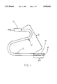
- FIG. 1 describes a perspective view of an implantable electrode of the present invention incorporating a single conductive portion.
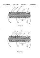
- FIGS. 2 and 2A describe alternative cross sections of the implantable electrode of FIG. 1.
- FIG. 3 describes a perspective view of a preferred embodiment of the implantable electrode incorporating two conductive portions.
- FIG. 4 describes a cross section of the implantable electrode of FIG. 3.
- FIG. 4A describes an alternative embodiment to the implantable electrode shown by FIG. 4 wherein the insulating portion has an exterior layer of porous polymeric material with an underlying layer of impermeable polymeric insulating material.
- FIG. 5 describes a cross section of an alternative to the embodiment of FIGS. 3 and 4 incorporating a different tip construction.
- FIG. 6 describes a cross section of an alternative to the embodiment of FIG. 3 wherein the porous PTFE insulating material and the porous PTFE conductive material are secured to the surface of the helically wound conductor by a layer of an adhesive.
- FIG. 7 describes a cross section of an alternative to the embodiment of FIG. 3 wherein the two helically wound conductors within the insulating portion are in co-linear relationship.
- FIG. 8 is a schematic view of the implantable electrode of the present invention in use with a human heart.
- FIG. 1 shows the implantable electrode 10 of the present invention having an insulating portion 21, a conductive portion 23 and a conventional connector 11 terminating the proximal end of the electrode 10.
- electrical energy is supplied to the conductive portion 23 by a helically wound conductor 31.
- the insulating material 13 coaxially covering the insulating portion 21 is comprised of a layer of impermeable polymeric electrically insulating material such as silicone tubing.
- the conductive portion 23 is comprised of an electrically conductive polymeric layer 15 which is electrically conductive in a dry state prior to implantation.
- the electrically conductive polymeric layer 15 is in direct electrical contact with the helically wound conductor 31 that supplies electrical energy to the conductive portion 23.
- This electrically conductive polymeric layer 15 is preferably comprised of a helically wrapped, porous PTFE tape containing a carbon filler wherein adjacent edges of the tape are overlapping.
- the porous PTFE containing a carbon filler is required to be of small pore size such as less than about 10 microns in order to limit tissue ingrowth.
- the distal end of this embodiment is covered by a cap 16 of either electrically conductive or electrically insulating material intended to close off the end of the tubular construction of the electrode 10.
- the use of an electrically conductive polymeric material as the tissue contacting portion of the electrode is a significant improvement over conventional transvenous defibrillator leads relying on direct contact between an exposed portion of a helically wound conductor and living tissue.
- the difficulty with these conventional transvenous defibrillator leads is that over time tissue grows into the exposed portion of the helically wound conductor with the result that it becomes very difficult to withdraw the lead by applying traction to the proximal end.
- the conductive portion 23 of the present invention is either non-porous or alternatively of a porous material having a pore size adequately small to substantially preclude tissue ingrowth. Adequately small pore sizes are typically of 10 micron diameter or smaller.
- Porous PTFE and particularly porous expanded PTFE are preferred materials for the exterior surfaces of both the insulating portion 21 and conductive portion 23 because the porous PTFE is a chemically inert material with a long history of use in implantable medical devices and is well known to produce very little adverse tissue reaction. Additionally, the porous nature of the material allows the implantable electrode to be highly flexible and kink resistant.
- the conductive porous PTFE for use as the electrically conductive polymeric layer that comprised the surface of the conductive portion 23 may be manufactured by uniformly distributing an electrically conductive filler throughout the porous PTFE during the process of making the porous PTFE layer.
- the electrically conductive particulate may be blended with the powdered PTFE resin prior to extrusion and expansion.
- Pore size of porous expanded PTFE is generally described as a function of the fibril length of the material.
- the fibril length of porous expanded PTFE is measured as taught by U.S. Pat. No. 4,972,846 except that a sample magnification level greater than 100 ⁇ may be necessary.
- FIG. 2A describes an alternative embodiment wherein an additional relatively short length of a helically wound conductor 32 is fitted coaxially over the distal end of the first helically wound conductor 31 for the length of the conductive portion 23. At least a portion of the additional relatively short length of helically wound conductor 32 is in direct electrical contact with the first helically wound conductor 31.
- the use of the additional relatively short length of helically wound conductor 32 allows for a more corrosion resistant metal surface to which the electrically conductive polymer coaxial covering may be fitted.
- a preferred metal for the additional relatively short length of helically wound conductor 32 is titanium.
- FIG. 3 shows a perspective view of a preferred embodiment of the implantable electrode of the present invention incorporating two conductive portions 23 and 19.
- FIG. 4 describes a cross section of this embodiment.
- the first conductive portion 23 is comprised as described previously of a layer 15 of electrically conductive polymeric material in contact with the first helically wound conductor 31.
- the second conductive portion 19 is located at the distal tip of the implantable electrode 10 and is preferably comprised of conventional metallic electrode materials such as platinum, carbon or titanium and may optionally incorporate a means for passively or positively attaching to a tissue surface, such as a barb, tine or screw thread.
- the second conductive portion 19 is connected to a second helically wound conductor 33 which is located coaxially within the lumen of the first helically wound conductor 31 and separated from the first helically wound conductor 31 by an impermeable tubular electrically insulating layer 29 which is preferably silicone tubing.
- the first and second conductive portions 23 and 19 are separated axially by a segment of impermeable polymeric electrically insulating material 17 at the surface of the distal end of the electrode 10.
- FIG. 4A describes a cross section of an alternative embodiment to that described previously by FIG. 4.
- the insulating layer of FIG. 4A is comprised of separate inner and outer layers.
- Outer layer 41 is a coaxial covering of porous PTFE which is preferably porous expanded PTFE.
- the inner layer 43 is an impermeable polymeric electrically insulating layer.
- porous PTFE for the exterior surface of the insulating portion 21 requires the use of an underlying impermeable polymeric electrically insulating layer 43. This is because body fluids will wet through the porous PTFE exterior coaxial covering thereby negating its electrical insulating value. This is true even for small pore size insulating materials, for example, porous expanded PTFE of less than 10 micron fibril length.
- the impermeable polymeric electrically insulating layer may be any suitable material and may also serve as an adhesive to secure the exterior porous insulating material to the underlying electrical conductor.
- Suitable materials include silicone tubing, silicone adhesive, and fluoropolymer tubing or tapes that may be helically wrapped about the surface of the electrical conductor.
- FIG. 5 describes an alternative embodiment to those described previously by FIG. 3 and FIG. 4 wherein only the impermeable insulating tubular layer 29 separates the two electrodes at the surface of the implantable electrode 10.
- the additional layer of porous PTFE insulating material 17 described previously in the embodiment of FIG. 4 is omitted in this instance.
- FIG. 6 shows a section of an alternative embodiment of the type described previously in FIGS. 3 and 4 wherein the porous PTFE insulating material 41 comprising the surface of the insulating portion 21 of the implantable electrode 10 is secured to the helically wound conductor 31 by a layer of adhesive 43 which may optionally serve as the impermeable electrically insulating layer if the adhesive characteristics meet those requirements.
- the adhesive is preferably a thermoplastic adhesive which is preferably a fluoropolymer and most preferably FEP.
- the adhesive securing the porous PTFE insulating material 41 may be either continuous as shown by layer 43 or alternatively may be discontinuous. If the adhesive layer is discontinuous, the use of a separate impermeable electrically insulating layer will be required.
- the electrically conductive polymeric material 15 may also be secured by a layer of adhesive 46 which should be discontinuous in order to allow for good electrical contact with the helically wound conductor 31.
- the layer of adhesive 46 may be an electrically conductive adhesive and therefore may be applied continuously.
- non-conductive adhesive is a dispersion of water, fluorinated ethylene propylene (hereinafter FEP) in the form of a particulate and a surfactant, available from DuPont (Wilmington, Del.) under the product name Teflon® FEP 120 Aqueous Dispersion.
- FEP fluorinated ethylene propylene
- Teflon® FEP 120 Aqueous Dispersion It has surprisingly been found that a thin layer of non-conductive polymeric adhesive produces good adhesion with little additional electrical resistance.
- conductive fillers such as carbon black may be added to this dispersion in order to make it electrically conductive.
- Six percent acetylene black Shawinigan Acetylene Black, Gulf Canada Ltd., Montreal, Quebec, Canada
- This dispersion with and without acetylene black has been found useful to adhere the electrically conductive polymeric material of the electrode surface to the underlying helically wound conductor.
- the porous PTFE may be made in sheet form having a layer of either continuous or discontinuous thermoplastic adhesive applied to one side of the porous PTFE sheet.
- the composite may then be slit into relatively narrow lengths of tape for subsequent helical wrapping about the conductor wire surface with the adhesive side of the composite contacting the conductor and the porous PTFE side facing outwardly.
- the helically wrapped conductor may then be heated to a temperature above the melt point of the thermoplastic adhesive to cause effective bonding of the composite tape to the conductor surface.
- the process of making the porous PTFE material having a layer of either continuous or discontinuous thermoplastic adhesive comprises:
- a porous PTFE substrate usually in the form of a membrane of film, with a layer, usually a film of a thermoplastic polymer;
- step b) heating the composition obtained in step a) to a temperature above the melting point of the thermoplastic polymer;
- step b) stretching the heated composition of step b) while maintaining the temperature above the melting point of the thermoplastic polymer;
- the thermoplastic film can form a very thin, i.e., 9 micron or less thick, film on the surface of the expanded porous PTFE which is continuous and non-porous. Or, if the degree of stretching is great enough, the thermoplastic film will eventually rend and form rents.
- the rents are usually slit-like openings if the thermoplastic film is initially relatively thick, or are usually wider gaps or holes if the thermoplastic film is initially relatively thin. Such a film having gaps or holes is herein considered to be discontinuous.
- the thermoplastic film is preferably a fluoropolymer and most preferably FEP.
- the completed film may be slit into lengths of narrow tape for subsequent helical wrapping about the surface of an electrical conductor.
- FIG. 6 describes the porous PTFE insulating material 41 as being in the form of a continuous tube and the electrically conductive polymeric material 15 as being in the form of a helically wrapped tape, it is apparent that either continuous tubes or helically wrapped tapes may be used to provide the surface material for either the insulative portion 21 or the electrically conductive portion 23. Both the continuous tube covering and the helically wrapped covering may be secured as described by the thermoplastic adhesive.
- FIG. 7 describes a cross section of an alternative to the embodiment of FIG. 3 wherein the first 31 and second 33 helically wound conductors within the insulating portion are in co-linear relationship wherein the two insulated conductors are wound parallel to each other within the same helix.
- the first 31 and second 33 helically wound conductors are separately insulated wherein the first conductor 31 has a layer of insulation 47 electrically isolating it from the second conductor 33 which has its own layer of insulation 49.
- the first 31 and second 33 helically wound conductors are separated into a coaxial relationship wherein the layer of insulation 47 has been removed from the first helically wound conductor 31, thereby allowing conductor 31 to be in direct electrical contact with conductive portion 23.
- the first 31 and second 33 helically wound conductors are insulated from each other beginning from the proximal end of the conductive portion 23 by a layer of impermeable polymeric electrically insulating material 45 coaxially covering the second helically wound conductor 33 which is in turn electrically connected to a distal tip electrode 19.
- FIG. 8 describes a schematic view of an implantable electrode of the present invention in use as a transvenous defibrillator lead with a human heart.
Abstract
Description
Claims (19)
Priority Applications (1)
| Application Number | Priority Date | Filing Date | Title |
|---|---|---|---|
| US08/571,580 US5609622A (en) | 1993-02-01 | 1995-12-12 | Implantable electrode with conductive polytetrafluoroethylene elecrode |
Applications Claiming Priority (2)
| Application Number | Priority Date | Filing Date | Title |
|---|---|---|---|
| US1488293A | 1993-02-01 | 1993-02-01 | |
| US08/571,580 US5609622A (en) | 1993-02-01 | 1995-12-12 | Implantable electrode with conductive polytetrafluoroethylene elecrode |
Related Parent Applications (1)
| Application Number | Title | Priority Date | Filing Date |
|---|---|---|---|
| US1488293A Continuation | 1993-02-01 | 1993-02-01 |
Publications (1)
| Publication Number | Publication Date |
|---|---|
| US5609622A true US5609622A (en) | 1997-03-11 |
Family
ID=21768325
Family Applications (1)
| Application Number | Title | Priority Date | Filing Date |
|---|---|---|---|
| US08/571,580 Expired - Lifetime US5609622A (en) | 1993-02-01 | 1995-12-12 | Implantable electrode with conductive polytetrafluoroethylene elecrode |
Country Status (6)
| Country | Link |
|---|---|
| US (1) | US5609622A (en) |
| EP (1) | EP0681494B1 (en) |
| JP (1) | JPH08505539A (en) |
| CA (1) | CA2152604C (en) |
| DE (1) | DE69326080T2 (en) |
| WO (1) | WO1994017852A1 (en) |
Cited By (109)
| Publication number | Priority date | Publication date | Assignee | Title |
|---|---|---|---|---|
| US5755766A (en) * | 1997-01-24 | 1998-05-26 | Cardiac Pacemakers, Inc. | Open-ended intravenous cardiac lead |
| US5931862A (en) * | 1997-12-22 | 1999-08-03 | Pacesetter, Inc. | Medical lead and method of making and using with sodium sulfosuccinic ester |
| US5954760A (en) * | 1997-05-07 | 1999-09-21 | Pacesetter Ab | Helical winding for a cardiac lead |
| US6058332A (en) * | 1996-10-15 | 2000-05-02 | Angeion Corp. | System for anchoring mid-lead electrode on an endocardial catheter lead |
| WO2000025854A2 (en) | 1998-11-04 | 2000-05-11 | Gore Enterprise Holdings, Inc. | A high impedance, low polarization cardiac electrode |
| US6408199B1 (en) * | 2000-07-07 | 2002-06-18 | Biosense, Inc. | Bipolar mapping of intracardiac potentials with electrode having blood permeable covering |
| US6456888B1 (en) | 2000-08-18 | 2002-09-24 | Cardiac Pacemakers, Inc. | Geometry for coupling and electrode to a conductor |
| US6456889B2 (en) | 2000-05-15 | 2002-09-24 | Pacesetter, Inc. | Lead with polymeric tubular liner for guidewire and stylet insertion |
| US6456890B2 (en) | 2000-05-15 | 2002-09-24 | Pacesetter, Inc. | Lead with polymeric tubular liner for guidewire and stylet insertion |
| WO2002085425A1 (en) | 2001-04-20 | 2002-10-31 | Medtronic, Inc. | Enhanced chronic lead removal |
| WO2002089909A1 (en) | 2001-05-02 | 2002-11-14 | Gore Enterprise Holdings, Inc. | Defibrillation electrode cover |
| US20020171680A1 (en) * | 2001-03-30 | 2002-11-21 | International Business Machines | Method and apparatus for navigating a windowed operating environment |
| US6571125B2 (en) | 2001-02-12 | 2003-05-27 | Medtronic, Inc. | Drug delivery device |
| US20030139794A1 (en) * | 2002-01-18 | 2003-07-24 | Jenney Christopher R. | Body implantable lead including one or more conductive polymer electrodes and methods for fabricating same |
| US6671560B2 (en) | 1998-06-12 | 2003-12-30 | Cardiac Pacemakers, Inc. | Modified guidewire for left ventricular access lead |
| US20040039434A1 (en) * | 1999-09-16 | 2004-02-26 | Schrom Mark G. | Neurostimulating lead |
| US6704604B2 (en) | 2000-12-28 | 2004-03-09 | Medtronic, Inc. | System and method for promoting selective tissue in-growth for an implantable medical device |
| US20040068313A1 (en) * | 2002-10-04 | 2004-04-08 | Jenney Christopher R. | Body implantable lead comprising electrically conductive polymer conductors |
| US6720497B1 (en) * | 1996-09-12 | 2004-04-13 | Pacesetter Ab | Electrode cable for electrical stimulation |
| US20040111141A1 (en) * | 2002-12-06 | 2004-06-10 | Brabec Scott J. | Medical devices incorporating carbon nanotube material and methods of fabricating same |
| US20050060004A1 (en) * | 2003-09-12 | 2005-03-17 | Cooke Daniel J. | Expanded ultra-high molecular weight polyethylene in an electrical medical device |
| US20050080470A1 (en) * | 2003-10-09 | 2005-04-14 | Randy Westlund | Intramyocardial lead implantation system and method |
| US20050085885A1 (en) * | 1998-08-12 | 2005-04-21 | Cardiac Pacemakers, Inc. | Expandable seal for use with medical device and system |
| US20050131511A1 (en) * | 2003-12-11 | 2005-06-16 | Randy Westlund | Cardiac lead having coated fixation arrangement |
| US6952616B2 (en) | 2000-09-26 | 2005-10-04 | Micronet Medical, Inc. | Medical lead and method for electrode attachment |
| US20050222659A1 (en) * | 2004-03-30 | 2005-10-06 | Medtronic, Inc. | Lead electrode for use in an MRI-safe implantable medical device |
| US20050222657A1 (en) * | 2004-03-30 | 2005-10-06 | Wahlstrand Carl D | MRI-safe implantable lead |
| US20050222658A1 (en) * | 2004-03-30 | 2005-10-06 | Medtronic, Inc. | Lead electrode for use in an MRI-safe implantable medical device |
| US20050222656A1 (en) * | 2004-03-30 | 2005-10-06 | Wahlstrand Carl D | MRI-safe implantable medical device |
| US20050228469A1 (en) * | 2004-04-12 | 2005-10-13 | Cardiac Pacemakers, Inc. | Electrode and conductor interconnect and method therefor |
| US20050227398A1 (en) * | 2000-10-20 | 2005-10-13 | Advanced Metal Coatings Pty Limited | Method of manufacturing an electrical lead |
| US7013182B1 (en) | 2000-05-04 | 2006-03-14 | Cardiac Pacemakers, Inc. | Conductive polymer sheath on defibrillator shocking coils |
| US7039470B1 (en) | 2000-09-26 | 2006-05-02 | Micronet Medical, Inc. | Medical lead and method for medical lead manufacture |
| US20060111768A1 (en) * | 2000-09-26 | 2006-05-25 | Micronet Medical, Inc. | Lead body and method of lead body construction |
| US20060200218A1 (en) * | 2005-02-01 | 2006-09-07 | Wahlstrand Carl D | Extensible implantable medical lead |
| US20060247748A1 (en) * | 2005-04-29 | 2006-11-02 | Medtronic, Inc. | Lead electrode for use in an MRI-safe implantable medical device |
| US20070075905A1 (en) * | 2005-10-05 | 2007-04-05 | Kenergy, Inc. | Radio frequency antenna for a wireless intravascular medical device |
| US20070154519A1 (en) * | 2005-12-29 | 2007-07-05 | Zhongping Yang | Self-assembling cross-linking molecular nano film |
| US20070217478A1 (en) * | 2004-05-17 | 2007-09-20 | Anders Carlsson | Measuring device |
| US20070225610A1 (en) * | 2006-03-27 | 2007-09-27 | Boston Scientific Scimed, Inc. | Capturing electrical signals with a catheter needle |
| US20080183261A1 (en) * | 2007-01-31 | 2008-07-31 | Cardiac Pacemakers, Inc. | Fibrosis-limiting material attachment |
| US20080195186A1 (en) * | 2007-02-14 | 2008-08-14 | Bernard Li | Continuous conductive materials for electromagnetic shielding |
| US20080195187A1 (en) * | 2007-02-14 | 2008-08-14 | Bernard Li | Discontinuous conductive filler polymer-matrix composites for electromagnetic shielding |
| US20080269863A1 (en) * | 2007-04-25 | 2008-10-30 | Medtronic, Inc. | Lead or lead extension having a conductive body and conductive body contact |
| US20090071686A1 (en) * | 2007-09-13 | 2009-03-19 | Medtronic, Inc. | Medical electrical lead |
| US20090125090A1 (en) * | 2005-05-31 | 2009-05-14 | Kenth Nilsson | Implantable medical lead |
| US20090138058A1 (en) * | 2004-12-17 | 2009-05-28 | Cardiac Pacemakers, Inc. | Mri operation modes for implantable medical devices |
| US20090149933A1 (en) * | 2007-12-06 | 2009-06-11 | Cardiac Pacemakers, Inc. | Implantable lead having a variable coil conductor pitch |
| US7561915B1 (en) | 2004-12-17 | 2009-07-14 | Cardiac Pacemakers, Inc. | MRI system having implantable device safety features |
| US20090281607A1 (en) * | 2008-05-07 | 2009-11-12 | Arnholt Devon N | Lead assembly and related methods |
| US20090287285A1 (en) * | 2008-05-07 | 2009-11-19 | Lynn Mark C | Lead assembly and related methods |
| US20090287286A1 (en) * | 2008-05-07 | 2009-11-19 | Lynn Mark C | Lead assembly and related methods |
| US20090319014A1 (en) * | 2008-05-07 | 2009-12-24 | David Muecke | Lead assembly and related methods |
| US20100004525A1 (en) * | 2008-07-05 | 2010-01-07 | Peter Osypka | Medical catheter with several poles or electrodes |
| US7657324B2 (en) | 1998-08-12 | 2010-02-02 | Cardiac Pacemakers, Inc. | Seal for use with cardiac lead |
| US20100036376A1 (en) * | 2004-08-05 | 2010-02-11 | Anderson Neil L | Process of Manufacturing a Medical Use Electrical Lead |
| US20100087892A1 (en) * | 2008-10-02 | 2010-04-08 | Stubbs Scott R | Implantable medical device responsive to mri induced capture threshold changes |
| US20100114285A1 (en) * | 2005-06-10 | 2010-05-06 | Rebecca Aron | Lead assembly with porous polyethylene cover |
| US20100121421A1 (en) * | 2008-11-07 | 2010-05-13 | Jeffrey B Duncan | Implantable lead |
| WO2010053585A1 (en) * | 2008-11-07 | 2010-05-14 | Gore Enterprise Holdings, Inc. | Implantable lead |
| US20100125321A1 (en) * | 2008-11-14 | 2010-05-20 | Lynn Mark C | Eptfe fill of coil filar gaps |
| US20100179298A1 (en) * | 2009-01-12 | 2010-07-15 | University Of Massachusetts Lowell | Polyisobutylene-Based Polyurethanes |
| US20100211123A1 (en) * | 2009-02-19 | 2010-08-19 | Stubbs Scott R | Systems and methods for providing arrhythmia therapy in mri environments |
| US20100228262A1 (en) * | 2009-03-04 | 2010-09-09 | Cully Edward H | Atraumatic lead removal sheath |
| US7853332B2 (en) | 2005-04-29 | 2010-12-14 | Medtronic, Inc. | Lead electrode for use in an MRI-safe implantable medical device |
| US20110046713A1 (en) * | 2009-03-04 | 2011-02-24 | Cully Edward H | Atraumatic vascular graft removal sheath |
| US20110087317A1 (en) * | 2006-03-29 | 2011-04-14 | Harshad Borgaonkar | Conductive polymeric coating with optional biobeneficial topcoat for a medical lead |
| US20110093054A1 (en) * | 2009-10-19 | 2011-04-21 | Masoud Ameri | Mri compatible tachycardia lead |
| US20110137359A1 (en) * | 2009-12-08 | 2011-06-09 | Stubbs Scott R | Implantable medical device with automatic tachycardia detection and control in mri environments |
| US20110160829A1 (en) * | 2009-12-31 | 2011-06-30 | Foster Arthur J | Mri conditionally safe lead with multi-layer conductor |
| US20110160818A1 (en) * | 2009-12-30 | 2011-06-30 | Roger Struve | Mri-conditionally safe medical device lead |
| US8032228B2 (en) | 2007-12-06 | 2011-10-04 | Cardiac Pacemakers, Inc. | Method and apparatus for disconnecting the tip electrode during MRI |
| US8086321B2 (en) | 2007-12-06 | 2011-12-27 | Cardiac Pacemakers, Inc. | Selectively connecting the tip electrode during therapy for MRI shielding |
| US8160717B2 (en) | 2008-02-19 | 2012-04-17 | Cardiac Pacemakers, Inc. | Model reference identification and cancellation of magnetically-induced voltages in a gradient magnetic field |
| US8311637B2 (en) | 2008-02-11 | 2012-11-13 | Cardiac Pacemakers, Inc. | Magnetic core flux canceling of ferrites in MRI |
| US8666508B2 (en) | 2008-02-06 | 2014-03-04 | Cardiac Pacemakers, Inc. | Lead with MRI compatible design features |
| US8666512B2 (en) | 2011-11-04 | 2014-03-04 | Cardiac Pacemakers, Inc. | Implantable medical device lead including inner coil reverse-wound relative to shocking coil |
| US8670840B2 (en) | 2006-11-30 | 2014-03-11 | Cardiac Pacemakers, Inc. | RF rejecting lead |
| US8676351B2 (en) | 2009-12-31 | 2014-03-18 | Cardiac Pacemakers, Inc. | MRI conditionally safe lead with low-profile multi-layer conductor for longitudinal expansion |
| US8688236B2 (en) | 2008-05-09 | 2014-04-01 | Cardiac Pacemakers, Inc. | Medical lead coil conductor with spacer element |
| WO2014033535A3 (en) * | 2012-08-31 | 2014-04-24 | Nexans | Cable electrode system for a device for reduction of unwanted organisms in a fish and/or shellfish corral/farm |
| US8744600B2 (en) | 2009-06-26 | 2014-06-03 | Cardiac Pacemakers, Inc. | Medical device lead including a unifilar coil with improved torque transmission capacity and reduced MRI heating |
| US8825181B2 (en) | 2010-08-30 | 2014-09-02 | Cardiac Pacemakers, Inc. | Lead conductor with pitch and torque control for MRI conditionally safe use |
| US8825179B2 (en) | 2012-04-20 | 2014-09-02 | Cardiac Pacemakers, Inc. | Implantable medical device lead including a unifilar coiled cable |
| US8903507B2 (en) | 2009-09-02 | 2014-12-02 | Cardiac Pacemakers, Inc. | Polyisobutylene urethane, urea and urethane/urea copolymers and medical leads containing the same |
| US8927660B2 (en) | 2009-08-21 | 2015-01-06 | Cardiac Pacemakers Inc. | Crosslinkable polyisobutylene-based polymers and medical devices containing the same |
| US8942823B2 (en) | 2009-09-02 | 2015-01-27 | Cardiac Pacemakers, Inc. | Medical devices including polyisobutylene based polymers and derivatives thereof |
| US8954168B2 (en) | 2012-06-01 | 2015-02-10 | Cardiac Pacemakers, Inc. | Implantable device lead including a distal electrode assembly with a coiled component |
| US8958889B2 (en) | 2012-08-31 | 2015-02-17 | Cardiac Pacemakers, Inc. | MRI compatible lead coil |
| US20150057521A1 (en) * | 2013-08-26 | 2015-02-26 | Biotronik Se & Co. Kg | Implantable device and production method for an implantable device |
| US8983623B2 (en) | 2012-10-18 | 2015-03-17 | Cardiac Pacemakers, Inc. | Inductive element for providing MRI compatibility in an implantable medical device lead |
| US8989840B2 (en) | 2004-03-30 | 2015-03-24 | Medtronic, Inc. | Lead electrode for use in an MRI-safe implantable medical device |
| US9084883B2 (en) | 2009-03-12 | 2015-07-21 | Cardiac Pacemakers, Inc. | Thin profile conductor assembly for medical device leads |
| US9186499B2 (en) | 2009-04-30 | 2015-11-17 | Medtronic, Inc. | Grounding of a shield within an implantable medical lead |
| US9265936B2 (en) | 2008-05-07 | 2016-02-23 | Cardiac Pacemakers, Inc. | Lead assembly and related methods |
| US20160263370A1 (en) * | 2013-12-05 | 2016-09-15 | Advanced Neuromodulation Systems, Inc. | Medical leads with segmented electrodes and methods of fabrication thereof |
| US9463317B2 (en) | 2012-04-19 | 2016-10-11 | Medtronic, Inc. | Paired medical lead bodies with braided conductive shields having different physical parameter values |
| US9504821B2 (en) | 2014-02-26 | 2016-11-29 | Cardiac Pacemakers, Inc. | Construction of an MRI-safe tachycardia lead |
| US9731119B2 (en) | 2008-03-12 | 2017-08-15 | Medtronic, Inc. | System and method for implantable medical device lead shielding |
| US9926399B2 (en) | 2012-11-21 | 2018-03-27 | University Of Massachusetts | High strength polyisobutylene polyurethanes |
| US9993638B2 (en) | 2013-12-14 | 2018-06-12 | Medtronic, Inc. | Devices, systems and methods to reduce coupling of a shield and a conductor within an implantable medical lead |
| US10155111B2 (en) | 2014-07-24 | 2018-12-18 | Medtronic, Inc. | Methods of shielding implantable medical leads and implantable medical lead extensions |
| US10173052B2 (en) | 2016-03-18 | 2019-01-08 | Teleflex Innovations S.À.R.L. | Pacing guidewire |
| US10279171B2 (en) | 2014-07-23 | 2019-05-07 | Medtronic, Inc. | Methods of shielding implantable medical leads and implantable medical lead extensions |
| US10526429B2 (en) | 2017-03-07 | 2020-01-07 | Cardiac Pacemakers, Inc. | Hydroboration/oxidation of allyl-terminated polyisobutylene |
| US10835638B2 (en) | 2017-08-17 | 2020-11-17 | Cardiac Pacemakers, Inc. | Photocrosslinked polymers for enhanced durability |
| US20200368401A1 (en) * | 2019-05-24 | 2020-11-26 | Conmed Corporation | Gap control in electrosurgical instruments using expanded polytetrafluoroethylene |
| EP3858424A1 (en) * | 2020-01-29 | 2021-08-04 | BIOTRONIK SE & Co. KG | Tube assembly and medical product comprising such a tube assembly |
| US11472911B2 (en) | 2018-01-17 | 2022-10-18 | Cardiac Pacemakers, Inc. | End-capped polyisobutylene polyurethane |
Families Citing this family (5)
| Publication number | Priority date | Publication date | Assignee | Title |
|---|---|---|---|---|
| US5571159A (en) * | 1994-04-04 | 1996-11-05 | Alt; Eckhard | Temporary atrial defibrillation catheter and method |
| US5861023A (en) * | 1997-12-16 | 1999-01-19 | Pacesetter, Inc. | Thrombus and tissue ingrowth inhibiting overlays for defibrillator shocking coil electrodes |
| US8649878B2 (en) | 2009-06-19 | 2014-02-11 | Greatbatch Ltd. | Temporary stimulation lead with polymer electrodes and method of manufacture |
| US8630718B2 (en) * | 2010-11-18 | 2014-01-14 | Cardiac Pacemakers, Inc. | Insulative structure for MRI compatible leads |
| DE102015121817A1 (en) | 2015-12-15 | 2017-06-22 | Biotronik Se & Co. Kg | Stretchable electrode |
Citations (36)
| Publication number | Priority date | Publication date | Assignee | Title |
|---|---|---|---|---|
| US3953566A (en) * | 1970-05-21 | 1976-04-27 | W. L. Gore & Associates, Inc. | Process for producing porous products |
| US4030509A (en) * | 1975-09-30 | 1977-06-21 | Mieczyslaw Mirowski | Implantable electrodes for accomplishing ventricular defibrillation and pacing and method of electrode implantation and utilization |
| US4033355A (en) * | 1975-11-28 | 1977-07-05 | Cardiac Pacemakers, Inc. | Electrode lead assembly for implantable devices and method of preparing same |
| US4096227A (en) * | 1973-07-03 | 1978-06-20 | W. L. Gore & Associates, Inc. | Process for producing filled porous PTFE products |
| US4280511A (en) * | 1980-02-25 | 1981-07-28 | Medtronic, Inc. | Ring electrode for pacing lead and process of making same |
| US4291707A (en) * | 1979-04-30 | 1981-09-29 | Mieczyslaw Mirowski | Implantable cardiac defibrillating electrode |
| US4328812A (en) * | 1980-03-21 | 1982-05-11 | Medtronic, Inc. | Ring electrode for pacing lead |
| US4458695A (en) * | 1982-07-16 | 1984-07-10 | Cordis Corporation | Multipolar electrode assembly for pacing lead |
| DE3305271A1 (en) * | 1983-02-16 | 1984-08-16 | Siemens AG, 1000 Berlin und 8000 München | ELECTRODE ARRANGEMENT |
| US4481953A (en) * | 1981-11-12 | 1984-11-13 | Cordis Corporation | Endocardial lead having helically wound ribbon electrode |
| US4499907A (en) * | 1982-11-15 | 1985-02-19 | Medtronic, Inc. | Energy limiting cardioversion lead |
| US4542752A (en) * | 1983-04-22 | 1985-09-24 | Cordis Corporation | Implantable device having porous surface with carbon coating |
| US4559951A (en) * | 1982-11-29 | 1985-12-24 | Cardiac Pacemakers, Inc. | Catheter assembly |
| US4576174A (en) * | 1982-07-08 | 1986-03-18 | Shionogi & Company, Ltd. | Micro electrode |
| CH656313A5 (en) * | 1982-05-24 | 1986-06-30 | Straumann Inst Ag | Electrode with an electrical conductor which is connected to a contact provided for forming a connection with tissue |
| US4641656A (en) * | 1985-06-20 | 1987-02-10 | Medtronic, Inc. | Cardioversion and defibrillation lead method |
| US4662377A (en) * | 1985-11-07 | 1987-05-05 | Mieczyslaw Mirowski | Cardioverting method and apparatus utilizing catheter and patch electrodes |
| GB2182566A (en) * | 1985-10-22 | 1987-05-20 | Telectronics Nv | Defibrillator electrode |
| US4690155A (en) * | 1985-07-03 | 1987-09-01 | Cordis Corporation | Monophasic action potential recording lead |
| DE3640033A1 (en) * | 1986-11-24 | 1988-05-26 | Siemens Ag | Pacemaker electrode |
| US4827932A (en) * | 1987-02-27 | 1989-05-09 | Intermedics Inc. | Implantable defibrillation electrodes |
| US4840186A (en) * | 1987-06-01 | 1989-06-20 | Siemens Aktiengesellschaft | Implantable multi-pole coaxial lead |
| DD269095A1 (en) * | 1987-12-21 | 1989-06-21 | Dresden Ultraschalltech | APPLICATION METHOD FOR ELECTRICALLY CONDUCTIVE POLYAETHYLENE FOR RING ELECTRODE TRANSVENOESIC ELECTRODE CATHETER |
| US4972846A (en) * | 1989-01-31 | 1990-11-27 | W. L. Gore & Associates, Inc. | Patch electrodes for use with defibrillators |
| US4985296A (en) * | 1989-03-16 | 1991-01-15 | W. L. Gore & Associates, Inc. | Polytetrafluoroethylene film |
| US5016646A (en) * | 1988-11-29 | 1991-05-21 | Telectronics, N.V. | Thin electrode lead and connections |
| US5087242A (en) * | 1989-07-21 | 1992-02-11 | Iomed, Inc. | Hydratable bioelectrode |
| US5090422A (en) * | 1990-04-19 | 1992-02-25 | Cardiac Pacemakers, Inc. | Implantable electrode pouch |
| US5111811A (en) * | 1985-06-20 | 1992-05-12 | Medtronic, Inc. | Cardioversion and defibrillation lead system with electrode extension into the coronary sinus and great vein |
| US5111812A (en) * | 1990-01-23 | 1992-05-12 | Cardiac Pacemakers, Inc. | Defilbrillation electrode having smooth current distribution |
| US5115818A (en) * | 1990-02-14 | 1992-05-26 | Medtronic, Inc. | Implantable electrode |
| EP0491979A1 (en) * | 1990-12-22 | 1992-07-01 | Peter Dr. Ing. Osypka | Pacemaker catheter with two poles |
| US5148806A (en) * | 1988-12-23 | 1992-09-22 | Yasuhiro Fukui | Electrode for use with a living body |
| US5165403A (en) * | 1991-02-26 | 1992-11-24 | Medtronic, Inc. | Difibrillation lead system and method of use |
| US5191901A (en) * | 1991-08-29 | 1993-03-09 | Mieczyslaw Mirowski | Controlled discharge defibrillation electrode |
| US5330520A (en) * | 1986-05-15 | 1994-07-19 | Telectronics Pacing Systems, Inc. | Implantable electrode and sensor lead apparatus |
-
1993
- 1993-06-16 EP EP93916575A patent/EP0681494B1/en not_active Expired - Lifetime
- 1993-06-16 DE DE69326080T patent/DE69326080T2/en not_active Expired - Lifetime
- 1993-06-16 JP JP6504456A patent/JPH08505539A/en active Pending
- 1993-06-16 WO PCT/US1993/005777 patent/WO1994017852A1/en active IP Right Grant
- 1993-06-16 CA CA002152604A patent/CA2152604C/en not_active Expired - Lifetime
-
1995
- 1995-12-12 US US08/571,580 patent/US5609622A/en not_active Expired - Lifetime
Patent Citations (37)
| Publication number | Priority date | Publication date | Assignee | Title |
|---|---|---|---|---|
| US3953566A (en) * | 1970-05-21 | 1976-04-27 | W. L. Gore & Associates, Inc. | Process for producing porous products |
| US4096227A (en) * | 1973-07-03 | 1978-06-20 | W. L. Gore & Associates, Inc. | Process for producing filled porous PTFE products |
| US4030509A (en) * | 1975-09-30 | 1977-06-21 | Mieczyslaw Mirowski | Implantable electrodes for accomplishing ventricular defibrillation and pacing and method of electrode implantation and utilization |
| US4033355A (en) * | 1975-11-28 | 1977-07-05 | Cardiac Pacemakers, Inc. | Electrode lead assembly for implantable devices and method of preparing same |
| US4291707A (en) * | 1979-04-30 | 1981-09-29 | Mieczyslaw Mirowski | Implantable cardiac defibrillating electrode |
| US4280511A (en) * | 1980-02-25 | 1981-07-28 | Medtronic, Inc. | Ring electrode for pacing lead and process of making same |
| US4328812A (en) * | 1980-03-21 | 1982-05-11 | Medtronic, Inc. | Ring electrode for pacing lead |
| US4481953A (en) * | 1981-11-12 | 1984-11-13 | Cordis Corporation | Endocardial lead having helically wound ribbon electrode |
| CH656313A5 (en) * | 1982-05-24 | 1986-06-30 | Straumann Inst Ag | Electrode with an electrical conductor which is connected to a contact provided for forming a connection with tissue |
| US4576174A (en) * | 1982-07-08 | 1986-03-18 | Shionogi & Company, Ltd. | Micro electrode |
| US4458695A (en) * | 1982-07-16 | 1984-07-10 | Cordis Corporation | Multipolar electrode assembly for pacing lead |
| US4499907A (en) * | 1982-11-15 | 1985-02-19 | Medtronic, Inc. | Energy limiting cardioversion lead |
| US4559951A (en) * | 1982-11-29 | 1985-12-24 | Cardiac Pacemakers, Inc. | Catheter assembly |
| US4573480A (en) * | 1983-02-16 | 1986-03-04 | Siemens Aktiengesellschaft | Implantable electrode lead with microporous insulation |
| DE3305271A1 (en) * | 1983-02-16 | 1984-08-16 | Siemens AG, 1000 Berlin und 8000 München | ELECTRODE ARRANGEMENT |
| US4542752A (en) * | 1983-04-22 | 1985-09-24 | Cordis Corporation | Implantable device having porous surface with carbon coating |
| US4641656A (en) * | 1985-06-20 | 1987-02-10 | Medtronic, Inc. | Cardioversion and defibrillation lead method |
| US5111811A (en) * | 1985-06-20 | 1992-05-12 | Medtronic, Inc. | Cardioversion and defibrillation lead system with electrode extension into the coronary sinus and great vein |
| US4690155A (en) * | 1985-07-03 | 1987-09-01 | Cordis Corporation | Monophasic action potential recording lead |
| GB2182566A (en) * | 1985-10-22 | 1987-05-20 | Telectronics Nv | Defibrillator electrode |
| US4662377A (en) * | 1985-11-07 | 1987-05-05 | Mieczyslaw Mirowski | Cardioverting method and apparatus utilizing catheter and patch electrodes |
| US5330520A (en) * | 1986-05-15 | 1994-07-19 | Telectronics Pacing Systems, Inc. | Implantable electrode and sensor lead apparatus |
| DE3640033A1 (en) * | 1986-11-24 | 1988-05-26 | Siemens Ag | Pacemaker electrode |
| US4827932A (en) * | 1987-02-27 | 1989-05-09 | Intermedics Inc. | Implantable defibrillation electrodes |
| US4840186A (en) * | 1987-06-01 | 1989-06-20 | Siemens Aktiengesellschaft | Implantable multi-pole coaxial lead |
| DD269095A1 (en) * | 1987-12-21 | 1989-06-21 | Dresden Ultraschalltech | APPLICATION METHOD FOR ELECTRICALLY CONDUCTIVE POLYAETHYLENE FOR RING ELECTRODE TRANSVENOESIC ELECTRODE CATHETER |
| US5016646A (en) * | 1988-11-29 | 1991-05-21 | Telectronics, N.V. | Thin electrode lead and connections |
| US5148806A (en) * | 1988-12-23 | 1992-09-22 | Yasuhiro Fukui | Electrode for use with a living body |
| US4972846A (en) * | 1989-01-31 | 1990-11-27 | W. L. Gore & Associates, Inc. | Patch electrodes for use with defibrillators |
| US4985296A (en) * | 1989-03-16 | 1991-01-15 | W. L. Gore & Associates, Inc. | Polytetrafluoroethylene film |
| US5087242A (en) * | 1989-07-21 | 1992-02-11 | Iomed, Inc. | Hydratable bioelectrode |
| US5111812A (en) * | 1990-01-23 | 1992-05-12 | Cardiac Pacemakers, Inc. | Defilbrillation electrode having smooth current distribution |
| US5115818A (en) * | 1990-02-14 | 1992-05-26 | Medtronic, Inc. | Implantable electrode |
| US5090422A (en) * | 1990-04-19 | 1992-02-25 | Cardiac Pacemakers, Inc. | Implantable electrode pouch |
| EP0491979A1 (en) * | 1990-12-22 | 1992-07-01 | Peter Dr. Ing. Osypka | Pacemaker catheter with two poles |
| US5165403A (en) * | 1991-02-26 | 1992-11-24 | Medtronic, Inc. | Difibrillation lead system and method of use |
| US5191901A (en) * | 1991-08-29 | 1993-03-09 | Mieczyslaw Mirowski | Controlled discharge defibrillation electrode |
Non-Patent Citations (4)
| Title |
|---|
| D Santel et al., Implantable Defibrillator Electrode System: A Brief Review PACE vol. 8, Jan. Feb. 1985, pp. 123 131. * |
| D Santel et al., Implantable Defibrillator Electrode System: A Brief Review PACE vol. 8, Jan.-Feb. 1985, pp. 123-131. |
| Stokes K, Implantable Pacing Lead Technology, IEEE Engineering in Medicine and Biology Mag. 1990; 9(02):43 49. * |
| Stokes K, Implantable Pacing Lead Technology, IEEE Engineering in Medicine and Biology Mag. 1990; 9(02):43-49. |
Cited By (225)
| Publication number | Priority date | Publication date | Assignee | Title |
|---|---|---|---|---|
| US6720497B1 (en) * | 1996-09-12 | 2004-04-13 | Pacesetter Ab | Electrode cable for electrical stimulation |
| US6058332A (en) * | 1996-10-15 | 2000-05-02 | Angeion Corp. | System for anchoring mid-lead electrode on an endocardial catheter lead |
| US5755766A (en) * | 1997-01-24 | 1998-05-26 | Cardiac Pacemakers, Inc. | Open-ended intravenous cardiac lead |
| WO1998032486A1 (en) * | 1997-01-24 | 1998-07-30 | Cardiac Pacemakers, Inc. | Cardiac lead arrangement |
| US5954760A (en) * | 1997-05-07 | 1999-09-21 | Pacesetter Ab | Helical winding for a cardiac lead |
| US5931862A (en) * | 1997-12-22 | 1999-08-03 | Pacesetter, Inc. | Medical lead and method of making and using with sodium sulfosuccinic ester |
| US6671560B2 (en) | 1998-06-12 | 2003-12-30 | Cardiac Pacemakers, Inc. | Modified guidewire for left ventricular access lead |
| US7657324B2 (en) | 1998-08-12 | 2010-02-02 | Cardiac Pacemakers, Inc. | Seal for use with cardiac lead |
| US20050085885A1 (en) * | 1998-08-12 | 2005-04-21 | Cardiac Pacemakers, Inc. | Expandable seal for use with medical device and system |
| US6901288B2 (en) | 1998-08-12 | 2005-05-31 | Cardiac Pacemakers, Inc. | Sealing assembly for intravenous lead |
| US7412290B2 (en) | 1998-08-12 | 2008-08-12 | Cardiac Pacemakers, Inc. | Seal for use with medical device and system |
| WO2000025854A3 (en) * | 1998-11-04 | 2000-08-03 | Gore Enterprise Holdings Inc | A high impedance, low polarization cardiac electrode |
| WO2000025854A2 (en) | 1998-11-04 | 2000-05-11 | Gore Enterprise Holdings, Inc. | A high impedance, low polarization cardiac electrode |
| US7047082B1 (en) | 1999-09-16 | 2006-05-16 | Micronet Medical, Inc. | Neurostimulating lead |
| US7051419B2 (en) | 1999-09-16 | 2006-05-30 | Micronet Medical, Inc. | Neurostimulating lead |
| US20040039434A1 (en) * | 1999-09-16 | 2004-02-26 | Schrom Mark G. | Neurostimulating lead |
| US7756589B2 (en) | 2000-05-04 | 2010-07-13 | Cardiac Pacemakers, Inc. | Conductive polymer sheath on defibrillator shocking coils |
| US7979142B2 (en) | 2000-05-04 | 2011-07-12 | Cardiac Pacemakers, Inc. | Conductive polymer sheath on defibrillator shocking coils |
| US20100241209A1 (en) * | 2000-05-04 | 2010-09-23 | Mohan Krishnan | Conductive polymer sheath on defibrillator shocking coils |
| US7013182B1 (en) | 2000-05-04 | 2006-03-14 | Cardiac Pacemakers, Inc. | Conductive polymer sheath on defibrillator shocking coils |
| US20060129217A1 (en) * | 2000-05-04 | 2006-06-15 | Cardiac Pacemakers, Inc. | Conductive polymer sheath on defibrillator shocking coils |
| US6456890B2 (en) | 2000-05-15 | 2002-09-24 | Pacesetter, Inc. | Lead with polymeric tubular liner for guidewire and stylet insertion |
| US6456889B2 (en) | 2000-05-15 | 2002-09-24 | Pacesetter, Inc. | Lead with polymeric tubular liner for guidewire and stylet insertion |
| US6408199B1 (en) * | 2000-07-07 | 2002-06-18 | Biosense, Inc. | Bipolar mapping of intracardiac potentials with electrode having blood permeable covering |
| US6663573B2 (en) | 2000-07-07 | 2003-12-16 | Biosense, Inc. | Bipolar mapping of intracardiac potentials using recessed electrodes |
| US6456888B1 (en) | 2000-08-18 | 2002-09-24 | Cardiac Pacemakers, Inc. | Geometry for coupling and electrode to a conductor |
| US7555349B2 (en) | 2000-09-26 | 2009-06-30 | Advanced Neuromodulation Systems, Inc. | Lead body and method of lead body construction |
| US20060111768A1 (en) * | 2000-09-26 | 2006-05-25 | Micronet Medical, Inc. | Lead body and method of lead body construction |
| US7039470B1 (en) | 2000-09-26 | 2006-05-02 | Micronet Medical, Inc. | Medical lead and method for medical lead manufacture |
| US6952616B2 (en) | 2000-09-26 | 2005-10-04 | Micronet Medical, Inc. | Medical lead and method for electrode attachment |
| US8150533B2 (en) | 2000-09-26 | 2012-04-03 | Advanced Neuromodulation Systems, Inc. | Medical lead and method for medical lead manufacture |
| US20050256557A1 (en) * | 2000-09-26 | 2005-11-17 | Wessman Bradley J | Medical lead and method for medical lead manufacture |
| US20100030308A1 (en) * | 2000-10-20 | 2010-02-04 | Cathrx Ltd. | Electrical lead |
| US7625617B1 (en) | 2000-10-20 | 2009-12-01 | Cathrx Ltd | Electrical lead |
| EP1916011A1 (en) | 2000-10-20 | 2008-04-30 | CathRx Ltd | An electrical lead |
| US20070220746A1 (en) * | 2000-10-20 | 2007-09-27 | Anderson Neil L | Method of manufacturing an electrical lead |
| US7629015B2 (en) | 2000-10-20 | 2009-12-08 | Cathrx Ltd | Method of manufacturing an electrical lead |
| US8075969B2 (en) | 2000-10-20 | 2011-12-13 | Cathrx Ltd | Electrical lead |
| US20050227398A1 (en) * | 2000-10-20 | 2005-10-13 | Advanced Metal Coatings Pty Limited | Method of manufacturing an electrical lead |
| US7079902B2 (en) | 2000-12-28 | 2006-07-18 | Medtronic, Inc. | System for promoting selective tissue in-growth for an implantable medical device |
| US6704604B2 (en) | 2000-12-28 | 2004-03-09 | Medtronic, Inc. | System and method for promoting selective tissue in-growth for an implantable medical device |
| US20040059402A1 (en) * | 2000-12-28 | 2004-03-25 | Medtronic, Inc. | System and method for promoting selective tissue in-growth for an implantable medical device |
| US6571125B2 (en) | 2001-02-12 | 2003-05-27 | Medtronic, Inc. | Drug delivery device |
| US6952809B2 (en) | 2001-03-30 | 2005-10-04 | International Business Machines Corporation | Method and apparatus for navigating a windowed operating environment |
| US20020171680A1 (en) * | 2001-03-30 | 2002-11-21 | International Business Machines | Method and apparatus for navigating a windowed operating environment |
| US20030028224A1 (en) * | 2001-04-20 | 2003-02-06 | Mcvenes Rick D. | Enhanced chronic lead removal |
| US6966322B2 (en) | 2001-04-20 | 2005-11-22 | Medtronic, Inc. | Enhanced chronic lead removal |
| WO2002085425A1 (en) | 2001-04-20 | 2002-10-31 | Medtronic, Inc. | Enhanced chronic lead removal |
| US7020529B2 (en) | 2001-05-02 | 2006-03-28 | Gore Enterprise Holdings, Inc. | Defibrillation electrode cover |
| WO2002089909A1 (en) | 2001-05-02 | 2002-11-14 | Gore Enterprise Holdings, Inc. | Defibrillation electrode cover |
| US20030139794A1 (en) * | 2002-01-18 | 2003-07-24 | Jenney Christopher R. | Body implantable lead including one or more conductive polymer electrodes and methods for fabricating same |
| US6999821B2 (en) | 2002-01-18 | 2006-02-14 | Pacesetter, Inc. | Body implantable lead including one or more conductive polymer electrodes and methods for fabricating same |
| US20040068313A1 (en) * | 2002-10-04 | 2004-04-08 | Jenney Christopher R. | Body implantable lead comprising electrically conductive polymer conductors |
| US7231259B2 (en) | 2002-10-04 | 2007-06-12 | Pacesetter, Inc. | Body implantable lead comprising electrically conductive polymer conductors |
| US20100324643A1 (en) * | 2002-12-06 | 2010-12-23 | Medtronic, Inc. | Medical Devices Incorporating Carbon Nanotube Material and Methods of Fabricating Same |
| US7844347B2 (en) * | 2002-12-06 | 2010-11-30 | Medtronic, Inc. | Medical devices incorporating carbon nanotube material and methods of fabricating same |
| US20040111141A1 (en) * | 2002-12-06 | 2004-06-10 | Brabec Scott J. | Medical devices incorporating carbon nanotube material and methods of fabricating same |
| US20050060004A1 (en) * | 2003-09-12 | 2005-03-17 | Cooke Daniel J. | Expanded ultra-high molecular weight polyethylene in an electrical medical device |
| US20050080470A1 (en) * | 2003-10-09 | 2005-04-14 | Randy Westlund | Intramyocardial lead implantation system and method |
| US20070173915A1 (en) * | 2003-12-11 | 2007-07-26 | Cardiac Pacemakers, Inc. | Cardiac lead having coated fixation arrangement |
| US20050131511A1 (en) * | 2003-12-11 | 2005-06-16 | Randy Westlund | Cardiac lead having coated fixation arrangement |
| US7197362B2 (en) | 2003-12-11 | 2007-03-27 | Cardiac Pacemakers, Inc. | Cardiac lead having coated fixation arrangement |
| US7844344B2 (en) * | 2004-03-30 | 2010-11-30 | Medtronic, Inc. | MRI-safe implantable lead |
| US20050222659A1 (en) * | 2004-03-30 | 2005-10-06 | Medtronic, Inc. | Lead electrode for use in an MRI-safe implantable medical device |
| US8989840B2 (en) | 2004-03-30 | 2015-03-24 | Medtronic, Inc. | Lead electrode for use in an MRI-safe implantable medical device |
| US20050222656A1 (en) * | 2004-03-30 | 2005-10-06 | Wahlstrand Carl D | MRI-safe implantable medical device |
| US7844343B2 (en) | 2004-03-30 | 2010-11-30 | Medtronic, Inc. | MRI-safe implantable medical device |
| US9155877B2 (en) | 2004-03-30 | 2015-10-13 | Medtronic, Inc. | Lead electrode for use in an MRI-safe implantable medical device |
| US7877150B2 (en) | 2004-03-30 | 2011-01-25 | Medtronic, Inc. | Lead electrode for use in an MRI-safe implantable medical device |
| US20050222658A1 (en) * | 2004-03-30 | 2005-10-06 | Medtronic, Inc. | Lead electrode for use in an MRI-safe implantable medical device |
| US20050222657A1 (en) * | 2004-03-30 | 2005-10-06 | Wahlstrand Carl D | MRI-safe implantable lead |
| US9302101B2 (en) | 2004-03-30 | 2016-04-05 | Medtronic, Inc. | MRI-safe implantable lead |
| US20050228469A1 (en) * | 2004-04-12 | 2005-10-13 | Cardiac Pacemakers, Inc. | Electrode and conductor interconnect and method therefor |
| US20070217478A1 (en) * | 2004-05-17 | 2007-09-20 | Anders Carlsson | Measuring device |
| US10668275B2 (en) | 2004-08-05 | 2020-06-02 | Cathrx Ltd | Electrical leads for medical use |
| US20100036376A1 (en) * | 2004-08-05 | 2010-02-11 | Anderson Neil L | Process of Manufacturing a Medical Use Electrical Lead |
| US8286338B2 (en) | 2004-08-05 | 2012-10-16 | Cathrx Ltd | Process of manufacturing a medical use electrical lead |
| US8014867B2 (en) | 2004-12-17 | 2011-09-06 | Cardiac Pacemakers, Inc. | MRI operation modes for implantable medical devices |
| US20090138058A1 (en) * | 2004-12-17 | 2009-05-28 | Cardiac Pacemakers, Inc. | Mri operation modes for implantable medical devices |
| US8543207B2 (en) | 2004-12-17 | 2013-09-24 | Cardiac Pacemakers, Inc. | MRI operation modes for implantable medical devices |
| US7561915B1 (en) | 2004-12-17 | 2009-07-14 | Cardiac Pacemakers, Inc. | MRI system having implantable device safety features |
| US8886317B2 (en) | 2004-12-17 | 2014-11-11 | Cardiac Pacemakers, Inc. | MRI operation modes for implantable medical devices |
| US20060200218A1 (en) * | 2005-02-01 | 2006-09-07 | Wahlstrand Carl D | Extensible implantable medical lead |
| US8280526B2 (en) * | 2005-02-01 | 2012-10-02 | Medtronic, Inc. | Extensible implantable medical lead |
| US20120330383A1 (en) * | 2005-02-01 | 2012-12-27 | Wahlstrand Carl D | Extensible Implantable Medical Lead |
| US10084250B2 (en) * | 2005-02-01 | 2018-09-25 | Medtronic, Inc. | Extensible implantable medical lead |
| US9265940B2 (en) * | 2005-04-29 | 2016-02-23 | Medtronic, Inc. | Lead electrode for use in an MRI-safe implantable medical device |
| US8027736B2 (en) | 2005-04-29 | 2011-09-27 | Medtronic, Inc. | Lead electrode for use in an MRI-safe implantable medical device |
| US7853332B2 (en) | 2005-04-29 | 2010-12-14 | Medtronic, Inc. | Lead electrode for use in an MRI-safe implantable medical device |
| US20060247748A1 (en) * | 2005-04-29 | 2006-11-02 | Medtronic, Inc. | Lead electrode for use in an MRI-safe implantable medical device |
| US20150039064A1 (en) * | 2005-04-29 | 2015-02-05 | Medtronic, Inc. | Lead electrode for use in an mri-safe implantable medical device |
| US9295833B2 (en) * | 2005-05-31 | 2016-03-29 | St. Jude Medical, AB | Implantable medical lead |
| US20090125090A1 (en) * | 2005-05-31 | 2009-05-14 | Kenth Nilsson | Implantable medical lead |
| US20100114285A1 (en) * | 2005-06-10 | 2010-05-06 | Rebecca Aron | Lead assembly with porous polyethylene cover |
| US8903511B2 (en) | 2005-06-10 | 2014-12-02 | Cardiac Pacemakers Inc. | Lead assembly with porous polyethylene cover |
| US7749265B2 (en) * | 2005-10-05 | 2010-07-06 | Kenergy, Inc. | Radio frequency antenna for a wireless intravascular medical device |
| US20070075905A1 (en) * | 2005-10-05 | 2007-04-05 | Kenergy, Inc. | Radio frequency antenna for a wireless intravascular medical device |
| US20070154519A1 (en) * | 2005-12-29 | 2007-07-05 | Zhongping Yang | Self-assembling cross-linking molecular nano film |
| US8535704B2 (en) | 2005-12-29 | 2013-09-17 | Medtronic, Inc. | Self-assembling cross-linking molecular nano film |
| US20070225610A1 (en) * | 2006-03-27 | 2007-09-27 | Boston Scientific Scimed, Inc. | Capturing electrical signals with a catheter needle |
| US20110087317A1 (en) * | 2006-03-29 | 2011-04-14 | Harshad Borgaonkar | Conductive polymeric coating with optional biobeneficial topcoat for a medical lead |
| US8670840B2 (en) | 2006-11-30 | 2014-03-11 | Cardiac Pacemakers, Inc. | RF rejecting lead |
| US20080183261A1 (en) * | 2007-01-31 | 2008-07-31 | Cardiac Pacemakers, Inc. | Fibrosis-limiting material attachment |
| US10537730B2 (en) | 2007-02-14 | 2020-01-21 | Medtronic, Inc. | Continuous conductive materials for electromagnetic shielding |
| US20080195186A1 (en) * | 2007-02-14 | 2008-08-14 | Bernard Li | Continuous conductive materials for electromagnetic shielding |
| US20080195187A1 (en) * | 2007-02-14 | 2008-08-14 | Bernard Li | Discontinuous conductive filler polymer-matrix composites for electromagnetic shielding |
| US9044593B2 (en) | 2007-02-14 | 2015-06-02 | Medtronic, Inc. | Discontinuous conductive filler polymer-matrix composites for electromagnetic shielding |
| US10398893B2 (en) | 2007-02-14 | 2019-09-03 | Medtronic, Inc. | Discontinuous conductive filler polymer-matrix composites for electromagnetic shielding |
| US8483842B2 (en) | 2007-04-25 | 2013-07-09 | Medtronic, Inc. | Lead or lead extension having a conductive body and conductive body contact |
| US9259572B2 (en) | 2007-04-25 | 2016-02-16 | Medtronic, Inc. | Lead or lead extension having a conductive body and conductive body contact |
| US20080269863A1 (en) * | 2007-04-25 | 2008-10-30 | Medtronic, Inc. | Lead or lead extension having a conductive body and conductive body contact |
| US8005550B2 (en) * | 2007-09-13 | 2011-08-23 | Medtronic, Inc. | Medical electrical lead |
| US9402989B2 (en) | 2007-09-13 | 2016-08-02 | Medtronic, Inc. | Medical electrical lead |
| US20090076579A1 (en) * | 2007-09-13 | 2009-03-19 | Medtronic, Inc. | Medical electrical lead |
| US20090076580A1 (en) * | 2007-09-13 | 2009-03-19 | Medtronic, Inc. | Medical electrical lead |
| US20090076578A1 (en) * | 2007-09-13 | 2009-03-19 | Medtronic, Inc. | Medical electrical lead |
| US20090071686A1 (en) * | 2007-09-13 | 2009-03-19 | Medtronic, Inc. | Medical electrical lead |
| US8032228B2 (en) | 2007-12-06 | 2011-10-04 | Cardiac Pacemakers, Inc. | Method and apparatus for disconnecting the tip electrode during MRI |
| US20090149933A1 (en) * | 2007-12-06 | 2009-06-11 | Cardiac Pacemakers, Inc. | Implantable lead having a variable coil conductor pitch |
| US8086321B2 (en) | 2007-12-06 | 2011-12-27 | Cardiac Pacemakers, Inc. | Selectively connecting the tip electrode during therapy for MRI shielding |
| US8897875B2 (en) | 2007-12-06 | 2014-11-25 | Cardiac Pacemakers, Inc. | Selectively connecting the tip electrode during therapy for MRI shielding |
| US8731685B2 (en) | 2007-12-06 | 2014-05-20 | Cardiac Pacemakers, Inc. | Implantable lead having a variable coil conductor pitch |
| US8554335B2 (en) | 2007-12-06 | 2013-10-08 | Cardiac Pacemakers, Inc. | Method and apparatus for disconnecting the tip electrode during MRI |
| US8666508B2 (en) | 2008-02-06 | 2014-03-04 | Cardiac Pacemakers, Inc. | Lead with MRI compatible design features |
| US8311637B2 (en) | 2008-02-11 | 2012-11-13 | Cardiac Pacemakers, Inc. | Magnetic core flux canceling of ferrites in MRI |
| US8160717B2 (en) | 2008-02-19 | 2012-04-17 | Cardiac Pacemakers, Inc. | Model reference identification and cancellation of magnetically-induced voltages in a gradient magnetic field |
| US9731119B2 (en) | 2008-03-12 | 2017-08-15 | Medtronic, Inc. | System and method for implantable medical device lead shielding |
| US8639356B2 (en) | 2008-05-07 | 2014-01-28 | Cardiac Pacemakers, Inc. | Lead assembly and related methods |
| US20090287286A1 (en) * | 2008-05-07 | 2009-11-19 | Lynn Mark C | Lead assembly and related methods |
| US9095702B2 (en) | 2008-05-07 | 2015-08-04 | Cardiac Pacemakers, Inc. | Lead assembly and related methods |
| US8401669B2 (en) * | 2008-05-07 | 2013-03-19 | Cardiac Pacemakers, Inc. | Lead assembly and related methods |
| US20090319014A1 (en) * | 2008-05-07 | 2009-12-24 | David Muecke | Lead assembly and related methods |
| US9265936B2 (en) | 2008-05-07 | 2016-02-23 | Cardiac Pacemakers, Inc. | Lead assembly and related methods |
| US20090281607A1 (en) * | 2008-05-07 | 2009-11-12 | Arnholt Devon N | Lead assembly and related methods |
| US20090287285A1 (en) * | 2008-05-07 | 2009-11-19 | Lynn Mark C | Lead assembly and related methods |
| US8688236B2 (en) | 2008-05-09 | 2014-04-01 | Cardiac Pacemakers, Inc. | Medical lead coil conductor with spacer element |
| US20100004525A1 (en) * | 2008-07-05 | 2010-01-07 | Peter Osypka | Medical catheter with several poles or electrodes |
| US8571661B2 (en) | 2008-10-02 | 2013-10-29 | Cardiac Pacemakers, Inc. | Implantable medical device responsive to MRI induced capture threshold changes |
| US20100087892A1 (en) * | 2008-10-02 | 2010-04-08 | Stubbs Scott R | Implantable medical device responsive to mri induced capture threshold changes |
| US9561378B2 (en) | 2008-10-02 | 2017-02-07 | Cardiac Pacemakers, Inc. | Implantable medical device responsive to MRI induced capture threshold changes |
| WO2010053585A1 (en) * | 2008-11-07 | 2010-05-14 | Gore Enterprise Holdings, Inc. | Implantable lead |
| US20100121421A1 (en) * | 2008-11-07 | 2010-05-13 | Jeffrey B Duncan | Implantable lead |
| CN103394158A (en) * | 2008-11-07 | 2013-11-20 | 戈尔企业控股股份有限公司 | Implantable lead |
| CN103394158B (en) * | 2008-11-07 | 2016-08-10 | W.L.戈尔及同仁股份有限公司 | Implantable lead |
| CN102209575B (en) * | 2008-11-07 | 2015-06-17 | 戈尔企业控股股份有限公司 | Implantable lead |
| CN102209575A (en) * | 2008-11-07 | 2011-10-05 | 戈尔企业控股股份有限公司 | Implantable lead |
| US20100137928A1 (en) * | 2008-11-07 | 2010-06-03 | Duncan Jeffrey B | Implantable lead |
| US8364281B2 (en) | 2008-11-07 | 2013-01-29 | W. L. Gore & Associates, Inc. | Implantable lead |
| US8996134B2 (en) | 2008-11-07 | 2015-03-31 | W. L. Gore & Associates, Inc. | Implantable lead |
| US9446232B2 (en) | 2008-11-07 | 2016-09-20 | W. L. Gore & Associates, Inc. | Implantable lead |
| US20100125321A1 (en) * | 2008-11-14 | 2010-05-20 | Lynn Mark C | Eptfe fill of coil filar gaps |
| US20100179298A1 (en) * | 2009-01-12 | 2010-07-15 | University Of Massachusetts Lowell | Polyisobutylene-Based Polyurethanes |
| US9574043B2 (en) | 2009-01-12 | 2017-02-21 | University Of Massachusetts Lowell | Polyisobutylene-based polyurethanes |
| US8962785B2 (en) | 2009-01-12 | 2015-02-24 | University Of Massachusetts Lowell | Polyisobutylene-based polyurethanes |
| US10513576B2 (en) | 2009-01-12 | 2019-12-24 | University of Masschusetts Lowell | Polyisobutylene-based polyurethanes |
| US11174336B2 (en) | 2009-01-12 | 2021-11-16 | University Of Massachusetts Lowell | Polyisobutylene-based polyurethanes |
| US20100211123A1 (en) * | 2009-02-19 | 2010-08-19 | Stubbs Scott R | Systems and methods for providing arrhythmia therapy in mri environments |
| US8639331B2 (en) | 2009-02-19 | 2014-01-28 | Cardiac Pacemakers, Inc. | Systems and methods for providing arrhythmia therapy in MRI environments |
| US8977356B2 (en) | 2009-02-19 | 2015-03-10 | Cardiac Pacemakers, Inc. | Systems and methods for providing arrhythmia therapy in MRI environments |
| US20100228262A1 (en) * | 2009-03-04 | 2010-09-09 | Cully Edward H | Atraumatic lead removal sheath |
| US8781601B2 (en) | 2009-03-04 | 2014-07-15 | W. L. Gore & Associates, Inc. | Atraumatic lead removal sheath |
| US8326437B2 (en) * | 2009-03-04 | 2012-12-04 | W. L. Gore & Associates, Inc. | Atraumatic lead removal sheath |
| US20110046713A1 (en) * | 2009-03-04 | 2011-02-24 | Cully Edward H | Atraumatic vascular graft removal sheath |
| US10045868B2 (en) * | 2009-03-04 | 2018-08-14 | W. L. Gore & Associates Inc. | Atraumatic vascular graft removal sheath |
| US9084883B2 (en) | 2009-03-12 | 2015-07-21 | Cardiac Pacemakers, Inc. | Thin profile conductor assembly for medical device leads |
| US10086194B2 (en) | 2009-04-30 | 2018-10-02 | Medtronic, Inc. | Termination of a shield within an implantable medical lead |
| US9629998B2 (en) | 2009-04-30 | 2017-04-25 | Medtronics, Inc. | Establishing continuity between a shield within an implantable medical lead and a shield within an implantable lead extension |
| US9272136B2 (en) | 2009-04-30 | 2016-03-01 | Medtronic, Inc. | Grounding of a shield within an implantable medical lead |
| US9186499B2 (en) | 2009-04-30 | 2015-11-17 | Medtronic, Inc. | Grounding of a shield within an implantable medical lead |
| US9452284B2 (en) | 2009-04-30 | 2016-09-27 | Medtronic, Inc. | Termination of a shield within an implantable medical lead |
| US9205253B2 (en) | 2009-04-30 | 2015-12-08 | Medtronic, Inc. | Shielding an implantable medical lead |
| US9216286B2 (en) | 2009-04-30 | 2015-12-22 | Medtronic, Inc. | Shielded implantable medical lead with guarded termination |
| US9220893B2 (en) | 2009-04-30 | 2015-12-29 | Medtronic, Inc. | Shielded implantable medical lead with reduced torsional stiffness |
| US10035014B2 (en) | 2009-04-30 | 2018-07-31 | Medtronic, Inc. | Steering an implantable medical lead via a rotational coupling to a stylet |
| US8744600B2 (en) | 2009-06-26 | 2014-06-03 | Cardiac Pacemakers, Inc. | Medical device lead including a unifilar coil with improved torque transmission capacity and reduced MRI heating |
| US8927660B2 (en) | 2009-08-21 | 2015-01-06 | Cardiac Pacemakers Inc. | Crosslinkable polyisobutylene-based polymers and medical devices containing the same |
| US8942823B2 (en) | 2009-09-02 | 2015-01-27 | Cardiac Pacemakers, Inc. | Medical devices including polyisobutylene based polymers and derivatives thereof |
| US8903507B2 (en) | 2009-09-02 | 2014-12-02 | Cardiac Pacemakers, Inc. | Polyisobutylene urethane, urea and urethane/urea copolymers and medical leads containing the same |
| US20110093054A1 (en) * | 2009-10-19 | 2011-04-21 | Masoud Ameri | Mri compatible tachycardia lead |
| US9254380B2 (en) | 2009-10-19 | 2016-02-09 | Cardiac Pacemakers, Inc. | MRI compatible tachycardia lead |
| US8565874B2 (en) | 2009-12-08 | 2013-10-22 | Cardiac Pacemakers, Inc. | Implantable medical device with automatic tachycardia detection and control in MRI environments |
| US20110137359A1 (en) * | 2009-12-08 | 2011-06-09 | Stubbs Scott R | Implantable medical device with automatic tachycardia detection and control in mri environments |
| US9381371B2 (en) | 2009-12-08 | 2016-07-05 | Cardiac Pacemakers, Inc. | Implantable medical device with automatic tachycardia detection and control in MRI environments |
| US9750944B2 (en) | 2009-12-30 | 2017-09-05 | Cardiac Pacemakers, Inc. | MRI-conditionally safe medical device lead |
| US20110160818A1 (en) * | 2009-12-30 | 2011-06-30 | Roger Struve | Mri-conditionally safe medical device lead |
| US9199077B2 (en) | 2009-12-31 | 2015-12-01 | Cardiac Pacemakers, Inc. | MRI conditionally safe lead with multi-layer conductor |
| US20110160829A1 (en) * | 2009-12-31 | 2011-06-30 | Foster Arthur J | Mri conditionally safe lead with multi-layer conductor |
| US9050457B2 (en) | 2009-12-31 | 2015-06-09 | Cardiac Pacemakers, Inc. | MRI conditionally safe lead with low-profile conductor for longitudinal expansion |
| US8676351B2 (en) | 2009-12-31 | 2014-03-18 | Cardiac Pacemakers, Inc. | MRI conditionally safe lead with low-profile multi-layer conductor for longitudinal expansion |
| US8798767B2 (en) | 2009-12-31 | 2014-08-05 | Cardiac Pacemakers, Inc. | MRI conditionally safe lead with multi-layer conductor |
| US8825181B2 (en) | 2010-08-30 | 2014-09-02 | Cardiac Pacemakers, Inc. | Lead conductor with pitch and torque control for MRI conditionally safe use |
| US8666512B2 (en) | 2011-11-04 | 2014-03-04 | Cardiac Pacemakers, Inc. | Implantable medical device lead including inner coil reverse-wound relative to shocking coil |
| US9463317B2 (en) | 2012-04-19 | 2016-10-11 | Medtronic, Inc. | Paired medical lead bodies with braided conductive shields having different physical parameter values |
| US8825179B2 (en) | 2012-04-20 | 2014-09-02 | Cardiac Pacemakers, Inc. | Implantable medical device lead including a unifilar coiled cable |
| US9333344B2 (en) | 2012-06-01 | 2016-05-10 | Cardiac Pacemakers, Inc. | Implantable device lead including a distal electrode assembly with a coiled component |
| US8954168B2 (en) | 2012-06-01 | 2015-02-10 | Cardiac Pacemakers, Inc. | Implantable device lead including a distal electrode assembly with a coiled component |
| CN104602513B (en) * | 2012-08-31 | 2017-03-29 | 尼克桑斯公司 | For the cable electrodes system of the equipment of the harmful organism in reducing Fish and/or shellfish culture fence/plant |
| US8958889B2 (en) | 2012-08-31 | 2015-02-17 | Cardiac Pacemakers, Inc. | MRI compatible lead coil |
| CN104602513A (en) * | 2012-08-31 | 2015-05-06 | 尼克桑斯公司 | Cable electrode system for a device for reduction of unwanted organisms in a fish and/or shellfish corral/farm |
| WO2014033535A3 (en) * | 2012-08-31 | 2014-04-24 | Nexans | Cable electrode system for a device for reduction of unwanted organisms in a fish and/or shellfish corral/farm |
| US9504822B2 (en) | 2012-10-18 | 2016-11-29 | Cardiac Pacemakers, Inc. | Inductive element for providing MRI compatibility in an implantable medical device lead |
| US8983623B2 (en) | 2012-10-18 | 2015-03-17 | Cardiac Pacemakers, Inc. | Inductive element for providing MRI compatibility in an implantable medical device lead |
| US9926399B2 (en) | 2012-11-21 | 2018-03-27 | University Of Massachusetts | High strength polyisobutylene polyurethanes |
| US10562998B2 (en) | 2012-11-21 | 2020-02-18 | University Of Massachusetts | High strength polyisobutylene polyurethanes |
| US20150057521A1 (en) * | 2013-08-26 | 2015-02-26 | Biotronik Se & Co. Kg | Implantable device and production method for an implantable device |
| US10285609B2 (en) * | 2013-08-26 | 2019-05-14 | Biotronik Se & Co. Kg | Implantable device and production method for an implantable device |
| US10226619B2 (en) * | 2013-12-05 | 2019-03-12 | Advanced Neuromodulation Systems, Inc. | Medical leads with segmented electrodes and methods of fabrication thereof |
| US11033733B2 (en) * | 2013-12-05 | 2021-06-15 | Advanced Neuromodulation Systems, Inc. | Medical leads with segmented electrodes and methods of fabrication thereof |
| US20160263370A1 (en) * | 2013-12-05 | 2016-09-15 | Advanced Neuromodulation Systems, Inc. | Medical leads with segmented electrodes and methods of fabrication thereof |
| US9993638B2 (en) | 2013-12-14 | 2018-06-12 | Medtronic, Inc. | Devices, systems and methods to reduce coupling of a shield and a conductor within an implantable medical lead |
| US9682231B2 (en) | 2014-02-26 | 2017-06-20 | Cardiac Pacemakers, Inc. | Construction of an MRI-safe tachycardia lead |
| US9504821B2 (en) | 2014-02-26 | 2016-11-29 | Cardiac Pacemakers, Inc. | Construction of an MRI-safe tachycardia lead |
| US10279171B2 (en) | 2014-07-23 | 2019-05-07 | Medtronic, Inc. | Methods of shielding implantable medical leads and implantable medical lead extensions |
| US10155111B2 (en) | 2014-07-24 | 2018-12-18 | Medtronic, Inc. | Methods of shielding implantable medical leads and implantable medical lead extensions |
| US10173052B2 (en) | 2016-03-18 | 2019-01-08 | Teleflex Innovations S.À.R.L. | Pacing guidewire |
| US10881851B2 (en) | 2016-03-18 | 2021-01-05 | Cardiac Interventions And Aviation Llc | Pacing guidewire |
| US10758725B2 (en) | 2016-03-18 | 2020-09-01 | Cardiac Interventions And Aviation Llc | Pacing guidewire |
| US11420046B2 (en) | 2016-03-18 | 2022-08-23 | Cardiac Interventions And Aviation Llc | Pacing guidewire |
| US10526429B2 (en) | 2017-03-07 | 2020-01-07 | Cardiac Pacemakers, Inc. | Hydroboration/oxidation of allyl-terminated polyisobutylene |
| US10835638B2 (en) | 2017-08-17 | 2020-11-17 | Cardiac Pacemakers, Inc. | Photocrosslinked polymers for enhanced durability |
| US11472911B2 (en) | 2018-01-17 | 2022-10-18 | Cardiac Pacemakers, Inc. | End-capped polyisobutylene polyurethane |
| US11851522B2 (en) | 2018-01-17 | 2023-12-26 | Cardiac Pacemakers, Inc. | End-capped polyisobutylene polyurethane |
| US20200368401A1 (en) * | 2019-05-24 | 2020-11-26 | Conmed Corporation | Gap control in electrosurgical instruments using expanded polytetrafluoroethylene |
| US11684702B2 (en) * | 2019-05-24 | 2023-06-27 | Conmed Corporation | Gap control in electrosurgical instruments using expanded polytetrafluoroethylene |
| EP3858424A1 (en) * | 2020-01-29 | 2021-08-04 | BIOTRONIK SE & Co. KG | Tube assembly and medical product comprising such a tube assembly |
Also Published As
| Publication number | Publication date |
|---|---|
| EP0681494A1 (en) | 1995-11-15 |
| JPH08505539A (en) | 1996-06-18 |
| WO1994017852A1 (en) | 1994-08-18 |
| DE69326080D1 (en) | 1999-09-23 |
| CA2152604C (en) | 2000-05-09 |
| DE69326080T2 (en) | 2000-03-09 |
| EP0681494B1 (en) | 1999-08-18 |
| CA2152604A1 (en) | 1994-08-18 |
Similar Documents
| Publication | Publication Date | Title |
|---|---|---|
| US5609622A (en) | Implantable electrode with conductive polytetrafluoroethylene elecrode | |
| JP3447737B2 (en) | Electrophysiological lead for implants | |
| US7835802B2 (en) | Polymer lead covering with varied material properties | |
| US5554176A (en) | Implantable electrode and sensor lead apparatus | |
| US5330520A (en) | Implantable electrode and sensor lead apparatus | |
| US7756589B2 (en) | Conductive polymer sheath on defibrillator shocking coils | |
| US8364281B2 (en) | Implantable lead | |
| US5861023A (en) | Thrombus and tissue ingrowth inhibiting overlays for defibrillator shocking coil electrodes | |
| US5016646A (en) | Thin electrode lead and connections | |
| US7149585B2 (en) | Lead body and method of lead body construction | |
| US7079902B2 (en) | System for promoting selective tissue in-growth for an implantable medical device | |
| EP0723788A1 (en) | Biocompatible medical lead | |
| US20080132984A1 (en) | Lead having composite insulative coating | |
| CA2108012A1 (en) | Defibrillator and demand pacer catheter and method | |
| US9095702B2 (en) | Lead assembly and related methods | |
| WO1980002231A1 (en) | Long-life flexible electrode lead | |
| US20090287286A1 (en) | Lead assembly and related methods | |
| US9265936B2 (en) | Lead assembly and related methods | |
| US20100125321A1 (en) | Eptfe fill of coil filar gaps |
Legal Events
| Date | Code | Title | Description |
|---|---|---|---|
| STCF | Information on status: patent grant |
Free format text: PATENTED CASE |
|
| AS | Assignment |
Owner name: GORE ENTERPRISE HOLDINGS, INC., DELAWARE Free format text: ASSIGNMENT OF ASSIGNORS INTEREST;ASSIGNOR:W.L. GORE & ASSOCIATES, INC.;REEL/FRAME:010175/0437 Effective date: 19990825 |
|
| FEPP | Fee payment procedure |
Free format text: PAYOR NUMBER ASSIGNED (ORIGINAL EVENT CODE: ASPN); ENTITY STATUS OF PATENT OWNER: LARGE ENTITY |
|
| FPAY | Fee payment |
Year of fee payment: 4 |
|
| FPAY | Fee payment |
Year of fee payment: 8 |
|
| FPAY | Fee payment |
Year of fee payment: 12 |
|
| REMI | Maintenance fee reminder mailed | ||
| AS | Assignment |
Owner name: W. L. GORE & ASSOCIATES, INC., DELAWARE Free format text: ASSIGNMENT OF ASSIGNORS INTEREST;ASSIGNOR:GORE ENTERPRISE HOLDINGS, INC.;REEL/FRAME:027906/0508 Effective date: 20120130 |