US5352215A - Y-adapter with a sideport radius - Google Patents
Y-adapter with a sideport radius Download PDFInfo
- Publication number
- US5352215A US5352215A US07/935,856 US93585692A US5352215A US 5352215 A US5352215 A US 5352215A US 93585692 A US93585692 A US 93585692A US 5352215 A US5352215 A US 5352215A
- Authority
- US
- United States
- Prior art keywords
- main body
- set forth
- invention further
- proximal
- passageway
- Prior art date
- Legal status (The legal status is an assumption and is not a legal conclusion. Google has not performed a legal analysis and makes no representation as to the accuracy of the status listed.)
- Expired - Lifetime
Links
Images

Classifications
-
- A—HUMAN NECESSITIES
- A61—MEDICAL OR VETERINARY SCIENCE; HYGIENE
- A61M—DEVICES FOR INTRODUCING MEDIA INTO, OR ONTO, THE BODY; DEVICES FOR TRANSDUCING BODY MEDIA OR FOR TAKING MEDIA FROM THE BODY; DEVICES FOR PRODUCING OR ENDING SLEEP OR STUPOR
- A61M39/00—Tubes, tube connectors, tube couplings, valves, access sites or the like, specially adapted for medical use
- A61M39/10—Tube connectors; Tube couplings
- A61M2039/1077—Adapters, e.g. couplings adapting a connector to one or several other connectors
-
- A—HUMAN NECESSITIES
- A61—MEDICAL OR VETERINARY SCIENCE; HYGIENE
- A61M—DEVICES FOR INTRODUCING MEDIA INTO, OR ONTO, THE BODY; DEVICES FOR TRANSDUCING BODY MEDIA OR FOR TAKING MEDIA FROM THE BODY; DEVICES FOR PRODUCING OR ENDING SLEEP OR STUPOR
- A61M39/00—Tubes, tube connectors, tube couplings, valves, access sites or the like, specially adapted for medical use
- A61M39/10—Tube connectors; Tube couplings
- A61M2039/1083—Tube connectors; Tube couplings having a plurality of female connectors, e.g. Luer connectors
-
- Y—GENERAL TAGGING OF NEW TECHNOLOGICAL DEVELOPMENTS; GENERAL TAGGING OF CROSS-SECTIONAL TECHNOLOGIES SPANNING OVER SEVERAL SECTIONS OF THE IPC; TECHNICAL SUBJECTS COVERED BY FORMER USPC CROSS-REFERENCE ART COLLECTIONS [XRACs] AND DIGESTS
- Y10—TECHNICAL SUBJECTS COVERED BY FORMER USPC
- Y10S—TECHNICAL SUBJECTS COVERED BY FORMER USPC CROSS-REFERENCE ART COLLECTIONS [XRACs] AND DIGESTS
- Y10S425/00—Plastic article or earthenware shaping or treating: apparatus
- Y10S425/058—Undercut
Definitions
- the present invention relates to an adapter for use with angioplasty catheters supplying fluid communication and or multiple guide wire introduction that has a hemo stasis capability.
- a catheter is placed into the vascular system of the patient, by first inserting a needle percutaneously into a blood vessel, and then inserting a wire through the needle lumen into the blood vessel, the needle is then removed, a sheath is inserted and the guide catheter is put in place.
- a guide catheter has a hub at its proximal end from which extends an elongated tubular portion that is open at its distal end. The guide wire is maneuvered and steered through the vascular system until its distal end extends past the area to be treated. With the guide catheter and wire in place, the balloon catheter is threaded through the lumen of the guide catheter.
- the un-inflated balloon portion of the catheter is located within the artery such that it crosses the stenosis or reduced area.
- Pressurized inflation fluid is delivered to the inflatable balloon through a lumen formed in the catheter to thus dilate the restricted area.
- the inflation fluid is generally a liquid and is applied at relatively high pressures. As the balloon is inflated it expands and forces open the stenoses or reduced area of the artery.
- the conventional Y-adapter has a main passageway and a branch passageway that joins the main passageway at an acute angle.
- a catheter or guide wire is inserted through the branch passageway its first obstacle that must be negotiate is the angle between the main and branch passageways.
- the lumens forming these passageways are generally straight and intersect at a sharp angle.
- the catheter In conventional Y-adapters the catheter is constrained by the internal surfaces of the passageways to a radius of approximately three-quarters of an inch or less.
- the elastic material from which the catheter is formed resist being bent around such a small radius.
- the resistance to being bent causes the catheter to be pressed against the internal surface of the passageways.
- the catheter As a result when the catheter is manipulated, twisted, pushed and pulled in an attempt to properly locate its distal end, its movement through the intersection is constrained and the rotational response is compromised.
- the catheter When the catheter is twisted or torqued it tends to wind up, with little or no immediate corresponding movement at the distal end. Then when the torque in the catheter reaches a certain level, it releases and unwinds or whips wildly. When this sudden release occurs the catheter is wildly and violently unwound and is whipped against the lumen walls and against the walls of the vascular system to which it is exposed.
- Another objective of the present invention is to provide an adapter with a branch lumen that is arcuate and smoothly merges into the straight lumen of the adapter.
- Another objective of the present invention is to provide a manufacturing process for producing the body portion of a Y-adapter that has an arcuate shaped branch lumen.
- Still another objective of the present invention is to provide an adapter that has a unique hemo stasis seal at the proximal end of the main port and an arcuate port that smoothly merges into the main port.
- the present invention provides a new and unique Y-adapter in which the lumen extending through the side arm is arcuate and smoothly merges into the lumen extending through the central arm.
- a preferred embodiment of the present invention includes a Y-adapter in which the lumen extending through the side arm is formed along the arc of a circle.
- a preferred embodiment of the hemo stasis seal has a generally tubular shape having spiral ribs formed along its outer surface.
- An important advantage of the present invention is that a catheter or guide wire can be smoothly inserted through the side arm of a Y-adapter into the central arm and then twisted and manipulated without distortion.
- arcuate side lumen and straight lumen can be accurately formed in the body portion of the Y-adapter in a molding process.
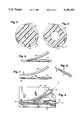
- FIG. 1 is an exploded cross sectional view of the Y-adapter.
- FIG. 2 is an exploded perspective view of the Y-adapter.
- FIG. 3 is a perspective view of the hemo stasis seal.
- FIG. 4 is a cross sectional view of the hemo stasis seal in its un-compressed condition.
- FIG. 5 is a cross sectional view of the hemo stasis seal in its compressed condition.
- FIG. 6 is a plan view of combined arcuate tapering core pin interfacing with the straight tapering core pin.
- FIG. 7 is a plan view of the arcuate tapering core pin.
- FIG. 8 is a perspective view of the straight tapering core pin.
- FIG. 9 is a mold for forming the body portion of the Y-adapter.
- FIG. 1 illustrates all of the components of the Y-adapter, unassembled but displayed along a dashed line along which the components would be moved in the assembly of the Y-adapter. In FIG. 1 all of the components are shown in cross section views.
- Main body 1 is molded from a plastic material such as polycarbonate, or other injection moldable polymer.
- the main body 1 has a straight port or passageway 6 formed therein extending from the proximal end 26 to the distal end 19.
- a cylindrical shaped opening 25, having a larger diameter than the straight port or passageway 6, is formed in the main body 1 at its proximal end 26.
- the O-shaped surface that extends between straight port 6 and the cylindrical shaped opening 25 functions as a seal seat 24 for the hemo stasis seal 5.
- the cylindrical shaped opening 25 is concentric with the straight port 6 and is also concentric with an outer cylindrical surface having outwardly facing threads 23 formed thereon. There is a continuous under cut 28 formed at the proximal end of the cylindrical shaped opening 25 extending toward the straight port 6.
- the main body 1 also has an arching port or passageway 7 formed therein.
- Arching port or passageway 7 is formed along the arc of a circle generated from a fixed point. The radius of this circle, in the preferred embodiment, being 2.55 ⁇ 0.50 inches.
- a standard female luer fitting 8 is formed at the proximal end of the arching port or passageway 7.
- Both straight port 6 and arching port 7 have circular cross sections and both have a slight taper along their length. Both ports 6 and 7 have a larger diameter at their proximal ends then at their distal ends. The purpose of this taper relates to the manufacturing process for the main body 1 which will be discussed in more detail with regard to FIGS. 6-9.
- the main body 1 has an external outer cylindrical surface at its distal end 19 that functions as a seat 22 for the o-ring 2.
- a collar is formed on the main body 1 adjacent the o-ring seat 22 that has a snap ring 21 along its outer periphery.
- the swivel male luer 3 is molded from a plastic material such as polycarbonate.
- a cylindrical bore 39 is formed in the proximal end of the swivel male luer 3 that functions as an o-ring seat 9.
- the o-ring 2 is a standard O-ring made from elastomeric material such as silicone.
- the swivel male luer 3 has a cylindrical bore 8 that is of a smaller diameter than cylindrical bore 39 formed concentric with bore 39 that functions to receive the distal end 19 of the main body 1.
- a standard male luer is formed at the distal end 10 of the swivel male luer 3.
- a thru hole 11 is formed through the center of the swivel male luer 3 that is aligned with the straight port 6 of the main body 1 when the swivel male luer 3 is assembled on the main body 1.
- the o-ring 2 is inserted into the O-ring seat 9 and the distal end 19 of the main body 1 is inserted into the proximal end of the swivel male luer 3 such that o-ring seat 22 extends through the O-ring 2 and the distal end 19 extends into the small cylindrical bore 38.
- the main body 1 is then forced into the swivel male luer 3, compressing O-ring 2 between O-ring seat 9 and O-ring seat 22 until snap ring 21 passes through the under cut 20.
- the thumb screw 4 is molded from plastic material, for example polycarbonate.
- the thumb screw 4 has a thru port 14 extending centrally therethrough which is flared outwardly at its proximal end.
- a cylindrical shaped groove, concentric with thru port 14, is formed in the distal end of thumb screw 4.
- a seal seat 13 is formed between the cylindrical shaped groove and the thru port 14 for a purpose to be discussed later in the specification.
- a snap ring 27 is formed along the outer periphery of the seal seat 13 extending toward the inwardly facing threads 12 that cooperates with the under cut 28 of the main body 1 to prevent unintentional release of the thumb screw 4 from the main body 1.
- the hemo stasis seal 5 is formed of elastomeric material, for example silicone. There is a thru hole 16 extending centrally of hemo stasis seal 5 that has distal and proximal sealing facings 18 at its extremities. There are a plurality of rotational limiting ribs 17 formed along the outer surface of the hemo stasis seal 5.
- the thumb screw 4 is assembled to the main body 1 by inserting the distal end of the thumb screw 4 into the cylindrical opening 25 such that the snap ring 27 extends past the under cut 28 of the main body 1.
- the purpose of the under cut 28 and snap ring 27 is to prevent the unintentional disconnection of the thumb screw 4 from the main body 1 when the inwardly facing threads 12 of the thumb screw 4 are no longer in engagement with the outwardly facing threads 23 of the main body 1.
- the thumb screw 4 is rotated in the clockwise direction to advance the thumb screw 4 toward the distal end 19 of the main body 1.
- the seal seat 13 of the thumb screw 4 engages the proximal sealing face 18 of the hemo stasis seal 5
- the distal sealing facing 18 of the hemo stasis seal 5 engages the seal seat 24 of the main body 1 and the outer surfaces of the rotational limiting ribs 17 engage the cylindrical surface of the cylindrical opening 25.
- Further rotation of the thumb screw 4 in the clockwise direction causes the hemo stasis seal 5 to be deformed and the thru hole 16 is compressed around an elongated element, for example a guide wire, that is extending therethrough thus forming a hemo stasis seal around the guide wire.
- FIG. 2 is a perspective view of the components that form the Y-adapter.
- the individual components are shown separated so that more of each component is visible.
- the components are aligned along an axis (not shown) that extends through the center of the straight port 6 of the main body 1.
- FIG. 2 supplements the understanding of the structure of the Y-adapter as described with reference to FIG. 1 since some elements of various components are better depicted in this perspective view than in the cross sectional view of FIG. 1.
- the stabilizing web 64 between the straight and arcuate passageways is seen in this view as well as the outwardly facing ribs 15 on the thumb screw 4.
- FIG. 3 is a perspective view of the hemo stasis seal 5 that is similar but larger then the illustration of this component in FIG. 2. It can be seen in FIG. 3 that the hemo stasis seal 5 has an upstanding ring 57 at its distal end and another upstanding ring 59 at its proximal end. The rings 57 and 59 are connected by the plurality of rotational limiting ribs 17. The height of the rings 57, 59 and the rotational limiting ribs 17 are the same and their outer surfaces form the outer surface of the hemo stasis seal 5. It should also be noted that frusto conical depressions 55 are formed in the distal and proximal sealing facings 18 of the hemo stasis seal 5.
- FIG. 4 is a cross section view taken along the central portion of the hemo stasis seal 5, when the seal is relaxed and not compressed. In this view the thru hole 16 is at its maximum size.
- FIG. 5 is a cross section view taken along the central portion of the hemo stasis seal 5, when the seal is under tension and compressed. In this view the thru hole 16 is shown reduced considerably from its maximum size as seen in FIG. 4.
- FIG. 6 is a plan view of the pins or cores 30 and 31 that are used to develop the straight port or passageway 6 and the arching port or passageway 7 when molding the main body 1.
- the arching and tapering pin or core 30 is used to form the arching port 7.
- Pin 30 is curved along the arc of a circle and is tapered slightly such that its cross sectional diameter is larger at the proximal end than at the distal end. In the preferred embodiment the radius of the arc for pin 30 is 2.55 ⁇ 0.25 inches.
- the pins 30 and 31 are shown nestled together.
- pins 30 and 31 are shown separated from each other. As can be best seen in FIG. 7 pin 30 is cut flat on mold shut off surface 32.
- Straight tapering pin 31, shown separated from pin 30 in FIG. 7, has a corresponding mold shut off surface.
- the mold shut off surface of pin 31 has a flat mold shut off surface 33 as well as a contoured mold shut off surface 34.
- the flat mold shut off surface 33 of pin 31 has the identical shape as the mold shut off surface 32 of pin 30 and the two surfaces fit flush together.
- the contoured mold shut off surface 34 of pin 31 is designed to match the outer surface of pin 30 so that the pins 30 and 31 can nestle closely together such that there will be no gaps along the intersection of the pins.
- the flat 33 and contoured 34 mold shut off surfaces of pin 31 can be best seen in the perspective view of FIG. 8. Pin 31 is slightly tapered such that it has a larger diameter at its proximal end then at its distal end.
- FIG. 9 wherein a part of the mold cavity block 70 is shown.
- the pins 30 and 31 are placed in the mold cavity prior to performing the molding operation and are supported by the cavity block 70 such that after the main body has been molded both ends of pins 30 and 31 are accessible from outside the molded main body.
- the plastic material from which main body 1 is made is injected into the mold and completely surrounds the pins 30 and 31.
- the main body has ports or passageways 6 and 7 that correspond in shape and size to the pins 30 and 31.
- the mold for main body 1 is designed such that after the molding process is completed the proximal and distal ends of the pins 30 and 31 are accessible through openings formed in the molded main body 1.
- the pins 30 and 31 are removed from the molded main body, for example, by exerting a force on the pins 30 and 31.
- the force can be a pushing force, represented by arrow 35 in FIG. 9 on the distal ends of pins 30 and 31, a pulling force, represented by arrows 36 and 37 in FIG. 9 on the proximal ends of pins 30 and 31 simultaneously exerting pushing 35 and pulling forces 36 and 37.
- the pins 30 and 31 are slightly tapered, having a larger cross sectional diameter at their proximal ends than at their distal ends.
- port 7 along the arc of a circle makes it possible to remove pin 30 from the molded main body 1. As pin 30 is being removed from the main body 1 it moves along an arc generated about the pins center. If pin 30 had a non circular curve it would be locked in the molded main body 1.
Abstract
Description
Claims (13)
Priority Applications (2)
| Application Number | Priority Date | Filing Date | Title |
|---|---|---|---|
| US07/935,856 US5352215A (en) | 1992-08-26 | 1992-08-26 | Y-adapter with a sideport radius |
| US08/273,811 US5470522A (en) | 1992-08-26 | 1994-07-12 | Method of molding Y-adapter with a sideport radius |
Applications Claiming Priority (1)
| Application Number | Priority Date | Filing Date | Title |
|---|---|---|---|
| US07/935,856 US5352215A (en) | 1992-08-26 | 1992-08-26 | Y-adapter with a sideport radius |
Related Child Applications (1)
| Application Number | Title | Priority Date | Filing Date |
|---|---|---|---|
| US08/273,811 Division US5470522A (en) | 1992-08-26 | 1994-07-12 | Method of molding Y-adapter with a sideport radius |
Publications (1)
| Publication Number | Publication Date |
|---|---|
| US5352215A true US5352215A (en) | 1994-10-04 |
Family
ID=25467788
Family Applications (2)
| Application Number | Title | Priority Date | Filing Date |
|---|---|---|---|
| US07/935,856 Expired - Lifetime US5352215A (en) | 1992-08-26 | 1992-08-26 | Y-adapter with a sideport radius |
| US08/273,811 Expired - Lifetime US5470522A (en) | 1992-08-26 | 1994-07-12 | Method of molding Y-adapter with a sideport radius |
Family Applications After (1)
| Application Number | Title | Priority Date | Filing Date |
|---|---|---|---|
| US08/273,811 Expired - Lifetime US5470522A (en) | 1992-08-26 | 1994-07-12 | Method of molding Y-adapter with a sideport radius |
Country Status (1)
| Country | Link |
|---|---|
| US (2) | US5352215A (en) |
Cited By (43)
| Publication number | Priority date | Publication date | Assignee | Title |
|---|---|---|---|---|
| US5478331A (en) * | 1994-05-11 | 1995-12-26 | Localmed, Inc. | Multi-function proximal end adapter for catheter |
| US5591137A (en) * | 1995-07-14 | 1997-01-07 | Merit Medical Systems, Inc. | Hemostasis valve with locking seal |
| US5613954A (en) * | 1994-11-21 | 1997-03-25 | Stryker Corporation | Laparoscopic surgical Y-tube cannula |
| US5755709A (en) * | 1996-04-25 | 1998-05-26 | Cuppy; Michael J. | Catheter system for percutaneously introducing a liquid |
| US5935112A (en) * | 1997-10-15 | 1999-08-10 | Stevens; Brian W. | Hemostasis valve with catheter/guidewire seals |
| US6015401A (en) * | 1993-08-09 | 2000-01-18 | Brackett; Jacqueline Darlene | Methods for vessel cannulation |
| US6146364A (en) * | 1996-12-27 | 2000-11-14 | Kawasumi Laboratories, Inc. | Medical device having a branch and process for producing the same |
| WO2002047742A2 (en) * | 2000-12-15 | 2002-06-20 | Alsius Corporation | Temperature sensor adapter for foley catheters |
| US6458103B1 (en) | 1998-10-23 | 2002-10-01 | Scimed Life Systems, Inc. | Axially activated hemostasis valve with lumen size selection |
| WO2004067077A1 (en) * | 2003-01-24 | 2004-08-12 | Medtronic Vascular, Inc. | Accessory for over the wire catheter with short wire capability |
| US20040181192A1 (en) * | 2003-03-11 | 2004-09-16 | Cuppy Michael John | Vascular access device and method of using same |
| US20050010238A1 (en) * | 2003-07-08 | 2005-01-13 | Potter Daniel J. | Detachable hemostasis valve and splittable sheath assembly |
| US20050033239A1 (en) * | 2003-08-06 | 2005-02-10 | Trivascular, Inc. | Passive hemostatic sheath valve |
| US20050085964A1 (en) * | 2003-10-21 | 2005-04-21 | Knapp Benjamin P. | Network coupled diagnosis and maintenance system |
| WO2005042077A1 (en) | 2003-10-22 | 2005-05-12 | Boston Scientific Limited | Catheter with a sidearm for delivery of antimicrobial agents to prevent infection |
| US7076285B2 (en) * | 1996-09-13 | 2006-07-11 | Scimed Life Systems, Inc. | Guide wire insertion and re-insertion tools and methods of use |
| US20060253088A1 (en) * | 2005-04-22 | 2006-11-09 | Mina Chow | Dual needle delivery system |
| US20070010796A1 (en) * | 2005-06-23 | 2007-01-11 | Derek Moran | Catheter device |
| US20070213812A1 (en) * | 2002-11-15 | 2007-09-13 | Webler William E | Apparatuses and methods for delivering/deploying a medical device in a vessel |
| US20080091137A1 (en) * | 2006-10-17 | 2008-04-17 | Reavill Matthew D | Apparatus and method of inserting an infusing catheter and determining catheter depth without a guidewire or direct contact with the catheter |
| US20090287167A1 (en) * | 2008-05-14 | 2009-11-19 | Becton, Dickinson And Company | Y-port device eliminating abberant currents |
| US7628775B2 (en) | 2004-09-24 | 2009-12-08 | Boston Scientific Scimed, Inc. | Safety Y-port adaptor and medical catheter assembly including the same |
| US7670316B2 (en) | 1996-09-13 | 2010-03-02 | Boston Scientific Corporation | Guidewire and catheter locking device and method |
| US20110060315A1 (en) * | 1996-09-13 | 2011-03-10 | Boston Scientific Scimed, Inc. | Multi-Size Convertible Catheter |
| US8343041B2 (en) | 2008-05-19 | 2013-01-01 | Boston Scientific Scimed, Inc. | Integrated locking device with passive sealing |
| US8372000B2 (en) | 2007-01-03 | 2013-02-12 | Boston Scientific Scimed, Inc. | Method and apparatus for biliary access and stone retrieval |
| US8388521B2 (en) | 2008-05-19 | 2013-03-05 | Boston Scientific Scimed, Inc. | Integrated locking device with active sealing |
| US8480570B2 (en) | 2007-02-12 | 2013-07-09 | Boston Scientific Scimed, Inc. | Endoscope cap |
| US20140066900A1 (en) * | 2012-09-06 | 2014-03-06 | Corindus, Inc. | System for guide catheter control |
| US8777931B2 (en) | 2011-08-19 | 2014-07-15 | Alcon Research, Ltd. | Retractable luer lock fittings |
| US20140316382A1 (en) * | 2003-09-26 | 2014-10-23 | Covidien Lp | Catheter and connector for use with same |
| WO2016048339A1 (en) * | 2014-09-26 | 2016-03-31 | Avent, Inc. | Single core pin assembly that creates two independent valve retainers for enteral feeding head |
| US10322275B2 (en) | 2015-10-30 | 2019-06-18 | ECMOtek, LLC | Devices for endovascular access through extracorporeal life support circuits |
| US10549071B2 (en) | 2013-10-15 | 2020-02-04 | Corindus, Inc. | Guide catheter control flexible track |
| US10737086B2 (en) | 2017-03-13 | 2020-08-11 | Boston Scientific Limited | Hemostasis valves and methods for making and using hemostasis valves |
| US20210077780A1 (en) * | 2019-09-13 | 2021-03-18 | Creganna Unlimited Company | Exit path connector for catheter assembly |
| US10953214B2 (en) | 2017-09-12 | 2021-03-23 | Boston Scientific Limited | Hemostasis valves and methods for making and using hemostasis valves |
| US10960501B2 (en) | 2017-03-13 | 2021-03-30 | Boston Scientific Limited | Hemostasis valves and methods for making and using hemostasis valves |
| US11064870B2 (en) | 2017-08-11 | 2021-07-20 | Boston Scientific Limited | Biopsy cap for use with endoscope |
| US11272946B2 (en) * | 2018-03-09 | 2022-03-15 | Acclarent, Inc. | Fluid fitting for dilation instrument |
| US11291821B2 (en) | 2017-03-13 | 2022-04-05 | Boston Scientific Limited | Hemostasis valves and methods for making and using hemostasis valves |
| USD969247S1 (en) * | 2020-03-10 | 2022-11-08 | P&P Imports LLC | Tubing component |
| USD970727S1 (en) | 2022-07-27 | 2022-11-22 | Omar Hassad | Intravenous Y-shaped adapter |
Families Citing this family (27)
| Publication number | Priority date | Publication date | Assignee | Title |
|---|---|---|---|---|
| US5824257A (en) * | 1997-02-14 | 1998-10-20 | Molex Incorporated | Molding core construction and process for molding of high-density electrical connector housings |
| ES2170646B1 (en) * | 2000-03-24 | 2004-01-01 | Gambero Jose Gali | PERFUSED PERFUSION PERFUSION EQUIPMENT. |
| US6399006B1 (en) | 2000-06-08 | 2002-06-04 | Entegris, Inc. | Process and apparatus for molding polymer sweep fittings |
| US8562583B2 (en) | 2002-03-26 | 2013-10-22 | Carmel Pharma Ab | Method and assembly for fluid transfer and drug containment in an infusion system |
| US7867215B2 (en) | 2002-04-17 | 2011-01-11 | Carmel Pharma Ab | Method and device for fluid transfer in an infusion system |
| EP1560622B1 (en) * | 2002-07-09 | 2008-03-05 | Carmel Pharma AB | A device for injecting medical substances |
| SE523001C2 (en) | 2002-07-09 | 2004-03-23 | Carmel Pharma Ab | Coupling component for transmitting medical substances, comprises connecting mechanism for releasable connection to second coupling component having further channel for creating coupling, where connecting mechanism is thread |
| CA2513705A1 (en) | 2003-01-21 | 2004-08-05 | Carmel Pharma Ab | A needle for penetrating a membrane |
| US20050033237A1 (en) * | 2003-08-08 | 2005-02-10 | James Fentress | Catheter assemblies and injection molding processes and equipment for making the same |
| US20060012650A1 (en) * | 2004-04-12 | 2006-01-19 | Seiko Epson Corporation | Liquid-supplying member, liquid-injection apparatus, mounting method, fluid-carrying tube, and manufacturing method of fluid-carrying tube |
| US7942860B2 (en) | 2007-03-16 | 2011-05-17 | Carmel Pharma Ab | Piercing member protection device |
| US7975733B2 (en) | 2007-05-08 | 2011-07-12 | Carmel Pharma Ab | Fluid transfer device |
| US8029747B2 (en) | 2007-06-13 | 2011-10-04 | Carmel Pharma Ab | Pressure equalizing device, receptacle and method |
| US8657803B2 (en) | 2007-06-13 | 2014-02-25 | Carmel Pharma Ab | Device for providing fluid to a receptacle |
| US8622985B2 (en) | 2007-06-13 | 2014-01-07 | Carmel Pharma Ab | Arrangement for use with a medical device |
| US10398834B2 (en) | 2007-08-30 | 2019-09-03 | Carmel Pharma Ab | Device, sealing member and fluid container |
| US8287513B2 (en) | 2007-09-11 | 2012-10-16 | Carmel Pharma Ab | Piercing member protection device |
| US8075550B2 (en) | 2008-07-01 | 2011-12-13 | Carmel Pharma Ab | Piercing member protection device |
| US8790330B2 (en) | 2008-12-15 | 2014-07-29 | Carmel Pharma Ab | Connection arrangement and method for connecting a medical device to the improved connection arrangement |
| US8523838B2 (en) | 2008-12-15 | 2013-09-03 | Carmel Pharma Ab | Connector device |
| US7943077B2 (en) * | 2009-06-30 | 2011-05-17 | Tyco Healthcare Group Lp | Method for manufacturing a catheter having a separated tip configuration |
| USD637713S1 (en) | 2009-11-20 | 2011-05-10 | Carmel Pharma Ab | Medical device adaptor |
| US8480646B2 (en) | 2009-11-20 | 2013-07-09 | Carmel Pharma Ab | Medical device connector |
| US9168203B2 (en) | 2010-05-21 | 2015-10-27 | Carmel Pharma Ab | Connectors for fluid containers |
| US8162013B2 (en) | 2010-05-21 | 2012-04-24 | Tobias Rosenquist | Connectors for fluid containers |
| US9034455B2 (en) * | 2012-06-28 | 2015-05-19 | Avent, Inc. | Branching core-pin assembly and system for forming branching channels |
| KR20170119106A (en) * | 2016-04-18 | 2017-10-26 | 이제범 | Catheter manufacturing apparatus |
Citations (32)
| Publication number | Priority date | Publication date | Assignee | Title |
|---|---|---|---|---|
| US701075A (en) * | 1902-02-19 | 1902-05-27 | Richard P Mccully | Catheter or like instrument. |
| US883583A (en) * | 1906-03-05 | 1908-03-31 | Joseph F Stallsmith | Stomach-pump. |
| US998339A (en) * | 1911-05-09 | 1911-07-18 | George B Dodge | Drainage-tube for embalmers' use. |
| US1505208A (en) * | 1923-10-01 | 1924-08-19 | Chester W Larner | Branch or y-pipe structure |
| US2308484A (en) * | 1939-01-16 | 1943-01-19 | Davol Rubber Co | Catheter |
| US2564977A (en) * | 1949-01-19 | 1951-08-21 | Hu Quang Hsi | Medical injecting apparatus |
| US3670729A (en) * | 1968-09-19 | 1972-06-20 | Alan E C Bennett | Transfusion needles |
| US4000739A (en) * | 1975-07-09 | 1977-01-04 | Cordis Corporation | Hemostasis cannula |
| US4046144A (en) * | 1975-09-18 | 1977-09-06 | Mcfarlane Richard H | Catheter placement assembly |
| US4096860A (en) * | 1975-10-08 | 1978-06-27 | Mclaughlin William F | Dual flow encatheter |
| US4198984A (en) * | 1978-05-04 | 1980-04-22 | The Kendall Company | Retaining member for a catheter side arm |
| US4207900A (en) * | 1978-07-03 | 1980-06-17 | The Kendall Company | Insert molded catheter and method |
| US4299226A (en) * | 1979-08-08 | 1981-11-10 | Banka Vidya S | Coronary dilation method |
| US4597756A (en) * | 1981-08-14 | 1986-07-01 | American Hospital Supply Corp | Angular implant device |
| US4600402A (en) * | 1984-12-18 | 1986-07-15 | The Kendall Company | Catheter with locking device |
| US4619643A (en) * | 1983-07-25 | 1986-10-28 | Bai Chao Liang | Catheter |
| US4668225A (en) * | 1985-12-23 | 1987-05-26 | Superior Healthcare Group, Inc. | Gastrostomy tube and gastrostomy-jejunal feeding tube combination |
| US4668226A (en) * | 1984-10-22 | 1987-05-26 | Olympus Optical Co., Ltd. | Injection needle assembly for endoscope |
| US4723550A (en) * | 1986-11-10 | 1988-02-09 | Cordis Corporation | Leakproof hemostasis valve with single valve member |
| US4726374A (en) * | 1985-12-09 | 1988-02-23 | Cordis Corporation | Leakproof hemostasis valve |
| US4730616A (en) * | 1983-08-12 | 1988-03-15 | Advanced Cardiovascular Systems, Inc. | Multiple probe angioplasty apparatus and method |
| US4752287A (en) * | 1986-12-30 | 1988-06-21 | Bioresearch, Inc. | Syringe check valve |
| US4886507A (en) * | 1988-02-01 | 1989-12-12 | Medex, Inc. | Y connector for angioplasty procedure |
| US4887997A (en) * | 1986-11-21 | 1989-12-19 | Sherwood Medical Company | Catheter for nasogastric intubation |
| US4935008A (en) * | 1988-07-20 | 1990-06-19 | Lewis Jr Ronald L | Double lumen introducing needle |
| US4969878A (en) * | 1986-03-18 | 1990-11-13 | Christoph Schmidt | Thick-walled flexible probe for insertion in the trachea or respectively in the bronchial system |
| US4995865A (en) * | 1989-06-09 | 1991-02-26 | Worldwide Medical Plastics Inc. | Multi-lumen catheters |
| US5009636A (en) * | 1989-12-06 | 1991-04-23 | The Kendall Company | Dual-lumen catheter apparatus and method |
| US5047021A (en) * | 1989-08-29 | 1991-09-10 | Utterberg David S | Male luer lock medical fitting |
| US5059186A (en) * | 1988-03-07 | 1991-10-22 | Vitaphore Corporation | Percutaneous access device |
| US5085645A (en) * | 1990-08-15 | 1992-02-04 | Becton, Dickinson And Company | Apparatus and method for a catheter adapter with valve |
| US5254097A (en) * | 1992-01-06 | 1993-10-19 | Datascope Investment Corp. | Combined percutaneous cardiopulmonary bypass (PBY) and intra-aortic balloon (IAB) access cannula |
Family Cites Families (5)
| Publication number | Priority date | Publication date | Assignee | Title |
|---|---|---|---|---|
| US3064310A (en) * | 1960-04-20 | 1962-11-20 | Drackett Co | Method and apparatus for making plastic articles |
| US3758253A (en) * | 1971-12-13 | 1973-09-11 | Aircraft Mechanics | Clay pipe fitting molding apparatus |
| JPS62249721A (en) * | 1986-04-23 | 1987-10-30 | Mazda Motor Corp | Apparatus for producing arc-shaped hollow plastics component |
| US4737334A (en) * | 1987-03-06 | 1988-04-12 | Hewlett-Packard Company | Plastic molding of an improved Luer nut |
| US5225215A (en) * | 1992-08-03 | 1993-07-06 | Syvrud Daniel J | Plastic molding apparatus |
-
1992
- 1992-08-26 US US07/935,856 patent/US5352215A/en not_active Expired - Lifetime
-
1994
- 1994-07-12 US US08/273,811 patent/US5470522A/en not_active Expired - Lifetime
Patent Citations (32)
| Publication number | Priority date | Publication date | Assignee | Title |
|---|---|---|---|---|
| US701075A (en) * | 1902-02-19 | 1902-05-27 | Richard P Mccully | Catheter or like instrument. |
| US883583A (en) * | 1906-03-05 | 1908-03-31 | Joseph F Stallsmith | Stomach-pump. |
| US998339A (en) * | 1911-05-09 | 1911-07-18 | George B Dodge | Drainage-tube for embalmers' use. |
| US1505208A (en) * | 1923-10-01 | 1924-08-19 | Chester W Larner | Branch or y-pipe structure |
| US2308484A (en) * | 1939-01-16 | 1943-01-19 | Davol Rubber Co | Catheter |
| US2564977A (en) * | 1949-01-19 | 1951-08-21 | Hu Quang Hsi | Medical injecting apparatus |
| US3670729A (en) * | 1968-09-19 | 1972-06-20 | Alan E C Bennett | Transfusion needles |
| US4000739A (en) * | 1975-07-09 | 1977-01-04 | Cordis Corporation | Hemostasis cannula |
| US4046144A (en) * | 1975-09-18 | 1977-09-06 | Mcfarlane Richard H | Catheter placement assembly |
| US4096860A (en) * | 1975-10-08 | 1978-06-27 | Mclaughlin William F | Dual flow encatheter |
| US4198984A (en) * | 1978-05-04 | 1980-04-22 | The Kendall Company | Retaining member for a catheter side arm |
| US4207900A (en) * | 1978-07-03 | 1980-06-17 | The Kendall Company | Insert molded catheter and method |
| US4299226A (en) * | 1979-08-08 | 1981-11-10 | Banka Vidya S | Coronary dilation method |
| US4597756A (en) * | 1981-08-14 | 1986-07-01 | American Hospital Supply Corp | Angular implant device |
| US4619643A (en) * | 1983-07-25 | 1986-10-28 | Bai Chao Liang | Catheter |
| US4730616A (en) * | 1983-08-12 | 1988-03-15 | Advanced Cardiovascular Systems, Inc. | Multiple probe angioplasty apparatus and method |
| US4668226A (en) * | 1984-10-22 | 1987-05-26 | Olympus Optical Co., Ltd. | Injection needle assembly for endoscope |
| US4600402A (en) * | 1984-12-18 | 1986-07-15 | The Kendall Company | Catheter with locking device |
| US4726374A (en) * | 1985-12-09 | 1988-02-23 | Cordis Corporation | Leakproof hemostasis valve |
| US4668225A (en) * | 1985-12-23 | 1987-05-26 | Superior Healthcare Group, Inc. | Gastrostomy tube and gastrostomy-jejunal feeding tube combination |
| US4969878A (en) * | 1986-03-18 | 1990-11-13 | Christoph Schmidt | Thick-walled flexible probe for insertion in the trachea or respectively in the bronchial system |
| US4723550A (en) * | 1986-11-10 | 1988-02-09 | Cordis Corporation | Leakproof hemostasis valve with single valve member |
| US4887997A (en) * | 1986-11-21 | 1989-12-19 | Sherwood Medical Company | Catheter for nasogastric intubation |
| US4752287A (en) * | 1986-12-30 | 1988-06-21 | Bioresearch, Inc. | Syringe check valve |
| US4886507A (en) * | 1988-02-01 | 1989-12-12 | Medex, Inc. | Y connector for angioplasty procedure |
| US5059186A (en) * | 1988-03-07 | 1991-10-22 | Vitaphore Corporation | Percutaneous access device |
| US4935008A (en) * | 1988-07-20 | 1990-06-19 | Lewis Jr Ronald L | Double lumen introducing needle |
| US4995865A (en) * | 1989-06-09 | 1991-02-26 | Worldwide Medical Plastics Inc. | Multi-lumen catheters |
| US5047021A (en) * | 1989-08-29 | 1991-09-10 | Utterberg David S | Male luer lock medical fitting |
| US5009636A (en) * | 1989-12-06 | 1991-04-23 | The Kendall Company | Dual-lumen catheter apparatus and method |
| US5085645A (en) * | 1990-08-15 | 1992-02-04 | Becton, Dickinson And Company | Apparatus and method for a catheter adapter with valve |
| US5254097A (en) * | 1992-01-06 | 1993-10-19 | Datascope Investment Corp. | Combined percutaneous cardiopulmonary bypass (PBY) and intra-aortic balloon (IAB) access cannula |
Cited By (78)
| Publication number | Priority date | Publication date | Assignee | Title |
|---|---|---|---|---|
| US6015401A (en) * | 1993-08-09 | 2000-01-18 | Brackett; Jacqueline Darlene | Methods for vessel cannulation |
| US5478331A (en) * | 1994-05-11 | 1995-12-26 | Localmed, Inc. | Multi-function proximal end adapter for catheter |
| US5613954A (en) * | 1994-11-21 | 1997-03-25 | Stryker Corporation | Laparoscopic surgical Y-tube cannula |
| US5591137A (en) * | 1995-07-14 | 1997-01-07 | Merit Medical Systems, Inc. | Hemostasis valve with locking seal |
| US5755709A (en) * | 1996-04-25 | 1998-05-26 | Cuppy; Michael J. | Catheter system for percutaneously introducing a liquid |
| US7670316B2 (en) | 1996-09-13 | 2010-03-02 | Boston Scientific Corporation | Guidewire and catheter locking device and method |
| US8043208B2 (en) | 1996-09-13 | 2011-10-25 | Boston Scientific Scimed, Inc. | Guide wire insertion and re-insertion tools and methods of use |
| US20100160726A1 (en) * | 1996-09-13 | 2010-06-24 | Boston Scientific Corporation | Guidewire and Catheter Locking Device and Method |
| US20100174139A1 (en) * | 1996-09-13 | 2010-07-08 | Boston Scientific Scimed, Inc. | Guide Wire Insertion and Re-Insertion Tools and Methods of Use |
| US20060247523A1 (en) * | 1996-09-13 | 2006-11-02 | Scimed Life Systems, Inc. | Guide wire insertion and re-insertion tools and methods of use |
| US7076285B2 (en) * | 1996-09-13 | 2006-07-11 | Scimed Life Systems, Inc. | Guide wire insertion and re-insertion tools and methods of use |
| US20110060315A1 (en) * | 1996-09-13 | 2011-03-10 | Boston Scientific Scimed, Inc. | Multi-Size Convertible Catheter |
| US7706861B2 (en) * | 1996-09-13 | 2010-04-27 | Boston Scientific Scimed, Inc. | Guide wire insertion and re-insertion tools and methods of use |
| US8343105B2 (en) | 1996-09-13 | 2013-01-01 | Boston Scientific Scimed, Inc. | Multi-size convertible catheter |
| US8206283B2 (en) | 1996-09-13 | 2012-06-26 | Boston Scientific Corporation | Guidewire and catheter locking device and method |
| US6146364A (en) * | 1996-12-27 | 2000-11-14 | Kawasumi Laboratories, Inc. | Medical device having a branch and process for producing the same |
| US5935112A (en) * | 1997-10-15 | 1999-08-10 | Stevens; Brian W. | Hemostasis valve with catheter/guidewire seals |
| US6458103B1 (en) | 1998-10-23 | 2002-10-01 | Scimed Life Systems, Inc. | Axially activated hemostasis valve with lumen size selection |
| WO2002047742A3 (en) * | 2000-12-15 | 2003-08-21 | Alsius Corp | Temperature sensor adapter for foley catheters |
| US20020077680A1 (en) * | 2000-12-15 | 2002-06-20 | Alsius | Temperature sensor adapter for foley catheters |
| WO2002047742A2 (en) * | 2000-12-15 | 2002-06-20 | Alsius Corporation | Temperature sensor adapter for foley catheters |
| US8187324B2 (en) | 2002-11-15 | 2012-05-29 | Advanced Cardiovascular Systems, Inc. | Telescoping apparatus for delivering and adjusting a medical device in a vessel |
| US20070213812A1 (en) * | 2002-11-15 | 2007-09-13 | Webler William E | Apparatuses and methods for delivering/deploying a medical device in a vessel |
| WO2004067077A1 (en) * | 2003-01-24 | 2004-08-12 | Medtronic Vascular, Inc. | Accessory for over the wire catheter with short wire capability |
| US20040181192A1 (en) * | 2003-03-11 | 2004-09-16 | Cuppy Michael John | Vascular access device and method of using same |
| US7985232B2 (en) * | 2003-07-08 | 2011-07-26 | St. Jude Medical, Atrial Fibrillation Division, Inc. | Detachable hemostasis valve and splittable sheath assembly |
| US20050010238A1 (en) * | 2003-07-08 | 2005-01-13 | Potter Daniel J. | Detachable hemostasis valve and splittable sheath assembly |
| US20050033239A1 (en) * | 2003-08-06 | 2005-02-10 | Trivascular, Inc. | Passive hemostatic sheath valve |
| WO2005016180A3 (en) * | 2003-08-06 | 2005-09-22 | Trivascular Inc | Passive hemostatic sheath valve |
| JP2007533341A (en) * | 2003-08-06 | 2007-11-22 | トライバスキュラー・インコーポレイテッド | Passive hemostatic sheath valve |
| US7901379B2 (en) | 2003-08-06 | 2011-03-08 | Trivascular, Inc. | Passive hemostatic sheath valve |
| US20060149294A1 (en) * | 2003-08-06 | 2006-07-06 | Boston Scientific Santa Rosa Corporation | Passive hemostatic sheath valve |
| US7241276B2 (en) * | 2003-08-06 | 2007-07-10 | Trivascular, Inc. | Passive hemostatic sheath valve |
| US20140316382A1 (en) * | 2003-09-26 | 2014-10-23 | Covidien Lp | Catheter and connector for use with same |
| US20050085964A1 (en) * | 2003-10-21 | 2005-04-21 | Knapp Benjamin P. | Network coupled diagnosis and maintenance system |
| WO2005042077A1 (en) | 2003-10-22 | 2005-05-12 | Boston Scientific Limited | Catheter with a sidearm for delivery of antimicrobial agents to prevent infection |
| US7628775B2 (en) | 2004-09-24 | 2009-12-08 | Boston Scientific Scimed, Inc. | Safety Y-port adaptor and medical catheter assembly including the same |
| US20060253088A1 (en) * | 2005-04-22 | 2006-11-09 | Mina Chow | Dual needle delivery system |
| US9950144B2 (en) | 2005-04-22 | 2018-04-24 | Advanced Cardiovascular Systems, Inc. | Dual needle delivery system |
| US9149602B2 (en) * | 2005-04-22 | 2015-10-06 | Advanced Cardiovascular Systems, Inc. | Dual needle delivery system |
| US7914519B2 (en) | 2005-06-23 | 2011-03-29 | Elcam Medical Agricultural Cooperative Association, Ltd. | Catheter device |
| US20070010796A1 (en) * | 2005-06-23 | 2007-01-11 | Derek Moran | Catheter device |
| US8029481B2 (en) | 2006-10-17 | 2011-10-04 | Matthew Dickson Reavill | Apparatus and method of inserting an infusing catheter and determining catheter depth without a guidewire or direct contact with the catheter |
| WO2008048524A1 (en) * | 2006-10-17 | 2008-04-24 | Reavill Matthew D | Apparatus for inserting an infusing catheter and determining catheter depth without a guidewire or direct contact with the catheter |
| US20080091137A1 (en) * | 2006-10-17 | 2008-04-17 | Reavill Matthew D | Apparatus and method of inserting an infusing catheter and determining catheter depth without a guidewire or direct contact with the catheter |
| US8372000B2 (en) | 2007-01-03 | 2013-02-12 | Boston Scientific Scimed, Inc. | Method and apparatus for biliary access and stone retrieval |
| US8888681B2 (en) | 2007-01-03 | 2014-11-18 | Boston Scientific Scimed, Inc. | Method and apparatus for biliary access and stone retrieval |
| US8480570B2 (en) | 2007-02-12 | 2013-07-09 | Boston Scientific Scimed, Inc. | Endoscope cap |
| US9131831B2 (en) | 2008-02-11 | 2015-09-15 | Boston Scientific Scimed, Inc. | Integrated locking device with passive sealing |
| US20090287167A1 (en) * | 2008-05-14 | 2009-11-19 | Becton, Dickinson And Company | Y-port device eliminating abberant currents |
| US8388521B2 (en) | 2008-05-19 | 2013-03-05 | Boston Scientific Scimed, Inc. | Integrated locking device with active sealing |
| US8343041B2 (en) | 2008-05-19 | 2013-01-01 | Boston Scientific Scimed, Inc. | Integrated locking device with passive sealing |
| US8777931B2 (en) | 2011-08-19 | 2014-07-15 | Alcon Research, Ltd. | Retractable luer lock fittings |
| US11413431B2 (en) | 2012-09-06 | 2022-08-16 | Corindus, Inc. | Hemostasis valve for guide catheter control |
| US9345859B2 (en) | 2012-09-06 | 2016-05-24 | Corindus, Inc. | Hemostasis valve and system for guide catheter control |
| US9452277B2 (en) | 2012-09-06 | 2016-09-27 | Corindus, Inc. | Hemostasis valve for guide catheter control |
| US10307570B2 (en) | 2012-09-06 | 2019-06-04 | Corindus, Inc. | Hemostasis valve for guide catheter control |
| US20140066900A1 (en) * | 2012-09-06 | 2014-03-06 | Corindus, Inc. | System for guide catheter control |
| US11801366B2 (en) | 2013-10-15 | 2023-10-31 | Corindus, Inc. | Guide catheter control flexible track |
| US11007348B2 (en) | 2013-10-15 | 2021-05-18 | Corindus, Inc. | Guide catheter control flexible track |
| US10549071B2 (en) | 2013-10-15 | 2020-02-04 | Corindus, Inc. | Guide catheter control flexible track |
| JP2017530034A (en) * | 2014-09-26 | 2017-10-12 | アヴェント インコーポレイテッド | Single core pin assembly forming two independent valve retainers for enteral feeding head |
| WO2016048339A1 (en) * | 2014-09-26 | 2016-03-31 | Avent, Inc. | Single core pin assembly that creates two independent valve retainers for enteral feeding head |
| US10207049B2 (en) | 2014-09-26 | 2019-02-19 | Avent, Inc. | Single core pin assembly that creates two independent valve retainers for enteral feeding head |
| AU2014407125B2 (en) * | 2014-09-26 | 2020-08-06 | Avent, Inc. | Single core pin assembly that creates two independent valve retainers for enteral feeding head |
| US10576260B2 (en) | 2015-10-30 | 2020-03-03 | ECMOtek, LLC | Devices for endovascular access through extracorporeal life support circuits |
| US10441774B2 (en) | 2015-10-30 | 2019-10-15 | ECMOtek, LLC | Devices for endovascular access through extracorporeal life support circuits |
| US10322275B2 (en) | 2015-10-30 | 2019-06-18 | ECMOtek, LLC | Devices for endovascular access through extracorporeal life support circuits |
| US10960501B2 (en) | 2017-03-13 | 2021-03-30 | Boston Scientific Limited | Hemostasis valves and methods for making and using hemostasis valves |
| US10737086B2 (en) | 2017-03-13 | 2020-08-11 | Boston Scientific Limited | Hemostasis valves and methods for making and using hemostasis valves |
| US11291821B2 (en) | 2017-03-13 | 2022-04-05 | Boston Scientific Limited | Hemostasis valves and methods for making and using hemostasis valves |
| US11064870B2 (en) | 2017-08-11 | 2021-07-20 | Boston Scientific Limited | Biopsy cap for use with endoscope |
| US10953214B2 (en) | 2017-09-12 | 2021-03-23 | Boston Scientific Limited | Hemostasis valves and methods for making and using hemostasis valves |
| US11272946B2 (en) * | 2018-03-09 | 2022-03-15 | Acclarent, Inc. | Fluid fitting for dilation instrument |
| US20210077780A1 (en) * | 2019-09-13 | 2021-03-18 | Creganna Unlimited Company | Exit path connector for catheter assembly |
| US11612720B2 (en) * | 2019-09-13 | 2023-03-28 | Creganna Unlimited Company | Exit path connector for catheter assembly |
| USD969247S1 (en) * | 2020-03-10 | 2022-11-08 | P&P Imports LLC | Tubing component |
| USD970727S1 (en) | 2022-07-27 | 2022-11-22 | Omar Hassad | Intravenous Y-shaped adapter |
Also Published As
| Publication number | Publication date |
|---|---|
| US5470522A (en) | 1995-11-28 |
Similar Documents
| Publication | Publication Date | Title |
|---|---|---|
| US5352215A (en) | Y-adapter with a sideport radius | |
| US5224939A (en) | Self locking guide catheter | |
| US6120480A (en) | Catheter introducer | |
| US6712791B2 (en) | Splittable medical valve | |
| US5554118A (en) | Universal mode vascular catheter system | |
| US5338314A (en) | Rotating Y-connector | |
| US6338725B1 (en) | Large-diameter introducer sheath having hemostasis valve and removable steering mechanism | |
| US4886507A (en) | Y connector for angioplasty procedure | |
| US5205831A (en) | Compression gasket for y-connector | |
| EP0900105B1 (en) | Hemostasis valve | |
| US5147336A (en) | Adapter kit for a catheter introducer | |
| US4360024A (en) | Catheter with liquid flow control means | |
| US5669881A (en) | Vascular introducer system incorporating inflatable occlusion balloon | |
| US4917667A (en) | Retroperfusion balloon catheter and method | |
| US5098396A (en) | Valve for an intravascular catheter device | |
| US20080071221A1 (en) | Connection assembly for use with splittable sheath | |
| US20010016704A1 (en) | Low profile fluid delivery and sealing system for a catheter | |
| US5800384A (en) | Multi-lumen percutaneous introducer | |
| EP3632502B1 (en) | Rotationally activated blood control | |
| WO2000078386A1 (en) | Integrated inflation/deflation device and method | |
| US20050096688A1 (en) | Gripper for catheter shaft | |
| CA2213382A1 (en) | Balloon catheter having palpitatable discharge valve and retention collar | |
| EP3352839B1 (en) | Cross slit gasket for introducer sheath | |
| US6685653B2 (en) | Extension system for pressure-sensing guidewires | |
| US20140276655A1 (en) | Drainage catheter with cutting tool |
Legal Events
| Date | Code | Title | Description |
|---|---|---|---|
| AS | Assignment |
Owner name: SCIMED LIFE SYSTEMS, INC., A MN CORP., MINNESOTA Free format text: ASSIGNMENT OF ASSIGNORS INTEREST.;ASSIGNORS:THOME, SCOTT P.;HOLMAN, THOMAS J.;REEL/FRAME:006242/0957;SIGNING DATES FROM 19920814 TO 19920821 |
|
| STCF | Information on status: patent grant |
Free format text: PATENTED CASE |
|
| FPAY | Fee payment |
Year of fee payment: 4 |
|
| FPAY | Fee payment |
Year of fee payment: 8 |
|
| REMI | Maintenance fee reminder mailed | ||
| FPAY | Fee payment |
Year of fee payment: 12 |
|
| AS | Assignment |
Owner name: BOSTON SCIENTIFIC SCIMED, INC., MINNESOTA Free format text: CHANGE OF NAME;ASSIGNOR:SCIMED LIFE SYSTEMS, INC.;REEL/FRAME:018505/0868 Effective date: 20050101 Owner name: BOSTON SCIENTIFIC SCIMED, INC.,MINNESOTA Free format text: CHANGE OF NAME;ASSIGNOR:SCIMED LIFE SYSTEMS, INC.;REEL/FRAME:018505/0868 Effective date: 20050101 |