US4900251A - Orthodontic archwire, apparatus, package and method - Google Patents
Orthodontic archwire, apparatus, package and method Download PDFInfo
- Publication number
- US4900251A US4900251A US07/187,735 US18773588A US4900251A US 4900251 A US4900251 A US 4900251A US 18773588 A US18773588 A US 18773588A US 4900251 A US4900251 A US 4900251A
- Authority
- US
- United States
- Prior art keywords
- orthodontic
- bend
- archwire
- wire
- lateral protrusion
- Prior art date
- Legal status (The legal status is an assumption and is not a legal conclusion. Google has not performed a legal analysis and makes no representation as to the accuracy of the status listed.)
- Expired - Lifetime
Links
Images
Classifications
-
- A—HUMAN NECESSITIES
- A61—MEDICAL OR VETERINARY SCIENCE; HYGIENE
- A61C—DENTISTRY; APPARATUS OR METHODS FOR ORAL OR DENTAL HYGIENE
- A61C7/00—Orthodontics, i.e. obtaining or maintaining the desired position of teeth, e.g. by straightening, evening, regulating, separating, or by correcting malocclusions
- A61C7/12—Brackets; Arch wires; Combinations thereof; Accessories therefor
- A61C7/20—Arch wires
Definitions
- This invention relates to improvements in the field of orthodontics It presents a new solution to a problem which has arisen with some modern archwires because they cannot easily be bent at their ends to prevent them from slipping excessively lengthwise, i.e. in the mesial-distal direction.
- a plurality of wire-receiving brackets are banded or bonded to the teeth, except that the distal molars are provided with tubes.
- a parabolic archwire has its opposite ends inserted in the molar tubes, and the archwire is inserted into wire-receiving slots of the brackets on the teeth.
- Ligature wires are used to tie the wire to the brackets. When attached to the brackets, the wire is under flexural and/or torsional stresses which, due to the resiliency of the vire, exert corrective tooth-moving forces on the teeth.
- brackets to which the invention is applicable have slots with measurements of 0.018 to 0.022 inch in the gingival-occlusal direction, when used with wires of square, round or rectangular cross section measuring, 0.014 to 0.0215 inch in the gingival-occlusal direction.
- Presently available small edgewise brackets have wire-receiving slots which measure 018 inch and, 0.025 inch ,respectively, in the gingival-occlusal and buccal-lingual directions.
- the corresponding measurements of the slots in heavy edgewise brackets measure 0.022 and 0.028 inch.
- Small and large edgewise brackets are used with round wires with diameters of 0.014, 0.016 and 0.018 inch; square wires measuring 0.016, 0.017 and 0.018 inch; and, rectangular wires measuring 0.016 ⁇ 0.022 inch, 0.016 ⁇ 0.025 inch, 0.017 ⁇ 0.022 inch, 0.017 ⁇ 0.025 inch, 0.018 ⁇ 0.022 inch, and 0.018 ⁇ 0.025 inch.
- large edgewise brackets are used with 0.020 inch and 0.022 inch round wires, 0.020 inch square wires, and rectangular wires which are 0.019 ⁇ 0.026 inch, 0.021 ⁇ 0.022 inch, 0.021 ⁇ 0.025 inch, and 0.0215 ⁇ 0.028 inch.
- an orthodontic archwire is a single piece of wire having a generally parabolic shape, with a slip-preventing lateral protrusion being provided approximately midway along the length of the wire.
- the lateral protrusion has a direction and size which is incapable of slipping through slots in orthodontic brackets.
- the lateral protrusion is a bend formed in the wire to occupy about 1 to 3 mm of the length of the wire.
- the bend has an overall height of at least 0.7 mm, and it has two legs which are equal in height and opposite in direction.
- the invention also involves an orthodontic apparatus including the type of archwire described in the preceding paragraph associated with orthodontic brackets which are attached to the central incisors of an orthodontic patient. Due to the inability of the lateral protrusion to slide through the bracket slots, the sliding movement of the archwire is limited in a mesial-distal direction.
- Another feature of the invention is a package which is used for supplying archwires to orthodontists.
- This package includes a container, and a plurality of archwires which are in the container.
- Each archwire has a localized lateral protrusion with a size and shape which is incapable of sliding through a bracket slot so that, when the wire is connected to orthodontic brackets in a patient's mouth, the presence of the protrusion will limit the extent of sliding movement of the wire.
- the archwires are of the type described above.
- a further feature of the invention pertains to the manufacturing and handling of orthodontic archwires whereby they are formed and shaped so that each wire is parabolic and has a lateral protrusion which has a size incapable of passing through the slot of an orthodontic bracket.
- a plurality of such archwires are sent from the manufacturing facility to an orthodontist for installation in patient's mouths.
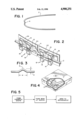
- FIG. 1 is a perspective view of an archwire which is constructed according to the invention.
- FIG. 2 is a perspective view of the archwire of FIG. 1 which is attached to brackets on the central incisors of an orthodontic patient.
- FIG. 3 is an enlarged frontal view of the bent portion of the wire.
- FIG. 4 shows a package which contains a plurality of preformed archwires made according to the invention.
- FIG. 5 is a flowchart illustrating some of the method aspects of the invention.
- FIG. 1 An archwire 2 used in connection with this invention is illustrated in FIG. 1. It has a generally parabolic shape and it is formed of an ultraelastic or shape memory alloy such as nitinol, a well-known alloy of nickel and titanium which is presently being used for orthodontic archwires.
- the vertex of the parabola will be located at the center of the dental arch of a patient where it will lie between orthodontic brackets which are mounted on the central incisors.
- the wire is identical to wires which have been commercially available for years.
- This bend constitutes a lateral protrusion which will prevent excessive slipping or sliding movement of the wire in a mesial-distal direction when installed in an orthodontic system.
- the bend can be formed with contouring pliers of the type commonly used in the practice of orthodontics, but it preferably is performed between a pair of matched dies for uniformity and to avoid or reduce any curvature adjacent to the bend in the gingival-occlusal direction.
- the use of dies for this purpose is not a feature of the present invention.
- FIG. 2 shows the vire tied to brackets 6 and 8 which are mounted on the central incisors of a patient's mouth.
- brackets 6 and 8 are conventional siamese brackets which have wire-receiving slots and ears.
- Ligature wires 10 and 12 are attached to the ears 14 and 16 in order to hold the archwire in the bracket slots.
- the brackets have bases provided with means for attaching them to teeth with adhesive or with a circumferential band 22 and 24 as is well known in orthodontic practice.
- the protrusion resulting from the V-shaped bend is sufficiently large than it cannot slip into or through the bracket slots. In this respect, the bend is surrounded so that the wire cannot slip a significant distance along its length which inherently substantially coincides with the mesial-distal axis of the dental arch.
- the overall height h of the wire 2 at the bend 4 is about two times the wire thickness t, and the length 1 of the bent section is about four times the thickness t of the wire.
- a suitable bend for a 0.018 inch wire has an overall height h of about 0.8 mm. and a length 1 of about 2 mm. The height should be at least about 0.7 mm. so that the bent section cannot slip into and through a bracket slot, and the length of the bend should from about 1 to 3 mm. It will be understood by persons in the art that, in this context, the height is measured in the gingival-occlusal direction, and the length is measured in the mesial-distal direction.
- a plurality of the archwires 2 are placed in a single box so there is a package including a plurality of archwires with the antislip bends formed therein. This is quite different from conventional practice in which such bends are not made by the manufacturers, and are not present in archwires sent to or received by orthodontic practitioners.
- the archwire is preshaped at the manufacturing facility into the configuration shown in FIG. 1. This involves the steps of bending it into the parabolic shape and forming the V-shaped bend to provide the lateral protrusion which has a size incapable of passing through the slots of an orthodontic bracket. A plurality of these preformed archwires are then sent from the manufacturer to the orthodontist who then installs them in the mouths of his or her patients, at which time the preformed bends are placed between the central incisor brackets as shown in FIG. 3 to deter the mesial-distal slippage of the wire in the patient's mouth.
- the wires may be formed of conventional stainless steel, but they preferably are formed of ultraelastic or shape memory alloys which pose particular problems due to their low coefficients of friction and their resistance to localized bending at the rear of the molar tubes. Suitable alloys are nickel titanium and ternary alloys of copper, zinc and aluminum. Various applicable compositions are disclosed in the Kirk-Othmer Encyclopedia of Chemical Technology, Third Edition volume 20, pages 726-736, John Wiley & Sons, 1982. This publication is incorporated herein by reference.
- the bend preferably has two legs which are equal in size and opposite in direction, but other shapes are possible. Attachments rather than bends may be used under some circumstances to provide lateral antislip protrusions.
Abstract
Description
Claims (23)
Priority Applications (1)
| Application Number | Priority Date | Filing Date | Title |
|---|---|---|---|
| US07/187,735 US4900251A (en) | 1988-04-29 | 1988-04-29 | Orthodontic archwire, apparatus, package and method |
Applications Claiming Priority (1)
| Application Number | Priority Date | Filing Date | Title |
|---|---|---|---|
| US07/187,735 US4900251A (en) | 1988-04-29 | 1988-04-29 | Orthodontic archwire, apparatus, package and method |
Publications (1)
| Publication Number | Publication Date |
|---|---|
| US4900251A true US4900251A (en) | 1990-02-13 |
Family
ID=22690245
Family Applications (1)
| Application Number | Title | Priority Date | Filing Date |
|---|---|---|---|
| US07/187,735 Expired - Lifetime US4900251A (en) | 1988-04-29 | 1988-04-29 | Orthodontic archwire, apparatus, package and method |
Country Status (1)
| Country | Link |
|---|---|
| US (1) | US4900251A (en) |
Cited By (29)
| Publication number | Priority date | Publication date | Assignee | Title |
|---|---|---|---|---|
| US5167499A (en) * | 1991-02-27 | 1992-12-01 | Arndt Wendell V | Ni-ti orthodontic palatal expansion arch |
| US5259760A (en) * | 1991-12-07 | 1993-11-09 | Tomy K.K. | Orthodontic arch wire |
| US5312247A (en) * | 1992-05-21 | 1994-05-17 | Ormco Corporation | Transpalatal orthodontic appliance of superelastic or shape-memory alloy |
| US5399087A (en) * | 1991-02-27 | 1995-03-21 | Arndt; Wendell V. | Ni-Ti orthodontic palatal expansion arch with cast lingual sheath and insert |
| US5538421A (en) * | 1993-07-16 | 1996-07-23 | Aspel; Thomas E. | Dental instrument |
| EP0750887A2 (en) * | 1995-06-28 | 1997-01-02 | Minnesota Mining And Manufacturing Company | Packaged orthodontic archwire assembly |
| US5711418A (en) * | 1996-03-29 | 1998-01-27 | Minnesota Mining And Manufacturing Co. | Packaged orthodontic archwire assembly |
| US5816800A (en) * | 1995-10-26 | 1998-10-06 | Ortho Organizers, Inc. | Palatal arch expander assembly and method of adjusting |
| US5885075A (en) * | 1996-05-07 | 1999-03-23 | Brilliant; Margo Kay | Orthodontic arch wire dispenser |
| US20070087301A1 (en) * | 2004-03-01 | 2007-04-19 | Ormco Corporation | Archwire assembly with stops |
| US20090215003A1 (en) * | 2008-02-27 | 2009-08-27 | Ryan B. Swain | Orthodontic kit and methods for same |
| US20100196839A1 (en) * | 2004-10-28 | 2010-08-05 | Rmo, Inc. | Orthodontic Bracket with Frangible Cover Mechanism |
| US20120070797A1 (en) * | 2010-09-22 | 2012-03-22 | Rmo, Inc. | Orthodontic Appliance and Method for Class II and Class III Malocclusion and Dental Asymmetric Correction |
| US8376739B2 (en) | 2011-05-12 | 2013-02-19 | Rmo, Inc. | Self ligating orthodontic bracket having a rotatable member |
| US8485816B2 (en) | 2009-03-16 | 2013-07-16 | Rmo, Inc. | Orthodontic bracket having an archwire channel and archwire retaining mechanism |
| US8585399B2 (en) | 2006-09-07 | 2013-11-19 | Rmo, Inc. | Reduced-friction buccal tube and method of use |
| US8979528B2 (en) | 2006-09-07 | 2015-03-17 | Rmo, Inc. | Customized orthodontic appliance method and system |
| US9554875B2 (en) | 2006-09-07 | 2017-01-31 | Rmo, Inc. | Method for producing a customized orthodontic appliance |
| USD847349S1 (en) | 2011-09-22 | 2019-04-30 | Rmo, Inc. | Orthodontic lock with flange |
| US10524883B2 (en) | 2016-11-08 | 2020-01-07 | Robert G. Larson | Orthodontic bracket |
| US10828133B2 (en) | 2016-12-02 | 2020-11-10 | Swift Health Systems Inc. | Indirect orthodontic bonding systems and methods for bracket placement |
| US10881489B2 (en) | 2017-01-31 | 2021-01-05 | Swift Health Systems Inc. | Hybrid orthodontic archwires |
| US11058520B2 (en) | 2012-10-30 | 2021-07-13 | University Of Southern California | Orthodontic appliance with snap fitted, non-sliding archwire |
| US11058517B2 (en) | 2017-04-21 | 2021-07-13 | Swift Health Systems Inc. | Indirect bonding trays, non-sliding orthodontic appliances, and registration systems for use thereof |
| US11219507B2 (en) | 2009-03-16 | 2022-01-11 | Orthoamerica Holdings, Llc | Customized orthodontic appliance and method |
| US11229505B2 (en) * | 2016-05-10 | 2022-01-25 | Pascal Roman Schumacher | Device for correcting misaligned teeth and method for production thereof |
| US11376102B2 (en) | 2016-11-08 | 2022-07-05 | Robert G. Larson | Orthodontic bracket |
| US11612458B1 (en) | 2017-03-31 | 2023-03-28 | Swift Health Systems Inc. | Method of tongue preconditioning in preparation for lingual orthodontic treatment |
| US11957536B2 (en) | 2020-11-25 | 2024-04-16 | Swift Health Systems Inc. | Hybrid orthodontic archwires |
Citations (5)
| Publication number | Priority date | Publication date | Assignee | Title |
|---|---|---|---|---|
| US1103606A (en) * | 1913-10-23 | 1914-07-14 | Christoph F Montag | Orthodontia-pliers. |
| US3055110A (en) * | 1960-08-08 | 1962-09-25 | Peter C Kesling | Buccal attachment |
| US3916526A (en) * | 1973-05-10 | 1975-11-04 | Fred Frank Schudy | Method and apparatus for orthodontic treatment |
| US4268250A (en) * | 1977-05-18 | 1981-05-19 | Reeve James J | Orthodontic appliance |
| US4424033A (en) * | 1982-08-02 | 1984-01-03 | Wool Arthur L | Orthodontic appliance |
-
1988
- 1988-04-29 US US07/187,735 patent/US4900251A/en not_active Expired - Lifetime
Patent Citations (5)
| Publication number | Priority date | Publication date | Assignee | Title |
|---|---|---|---|---|
| US1103606A (en) * | 1913-10-23 | 1914-07-14 | Christoph F Montag | Orthodontia-pliers. |
| US3055110A (en) * | 1960-08-08 | 1962-09-25 | Peter C Kesling | Buccal attachment |
| US3916526A (en) * | 1973-05-10 | 1975-11-04 | Fred Frank Schudy | Method and apparatus for orthodontic treatment |
| US4268250A (en) * | 1977-05-18 | 1981-05-19 | Reeve James J | Orthodontic appliance |
| US4424033A (en) * | 1982-08-02 | 1984-01-03 | Wool Arthur L | Orthodontic appliance |
Non-Patent Citations (2)
| Title |
|---|
| Cover, p. 10 and p. 11 from brochure entitled "A Guide for Using Nitinol Activ-Arch Wire". |
| Cover, p. 10 and p. 11 from brochure entitled A Guide for Using Nitinol Activ Arch Wire . * |
Cited By (55)
| Publication number | Priority date | Publication date | Assignee | Title |
|---|---|---|---|---|
| US5167499A (en) * | 1991-02-27 | 1992-12-01 | Arndt Wendell V | Ni-ti orthodontic palatal expansion arch |
| US5399087A (en) * | 1991-02-27 | 1995-03-21 | Arndt; Wendell V. | Ni-Ti orthodontic palatal expansion arch with cast lingual sheath and insert |
| USRE35170E (en) * | 1991-02-27 | 1996-03-05 | Arndt; Wendell V. | Ni-Ti orthodontic palatal expansion arch and method of imparting forces on teeth |
| US5259760A (en) * | 1991-12-07 | 1993-11-09 | Tomy K.K. | Orthodontic arch wire |
| US5312247A (en) * | 1992-05-21 | 1994-05-17 | Ormco Corporation | Transpalatal orthodontic appliance of superelastic or shape-memory alloy |
| US5538421A (en) * | 1993-07-16 | 1996-07-23 | Aspel; Thomas E. | Dental instrument |
| EP0750887A2 (en) * | 1995-06-28 | 1997-01-02 | Minnesota Mining And Manufacturing Company | Packaged orthodontic archwire assembly |
| EP0750887A3 (en) * | 1995-06-28 | 1997-05-07 | Minnesota Mining & Mfg | Packaged orthodontic archwire assembly |
| US5816800A (en) * | 1995-10-26 | 1998-10-06 | Ortho Organizers, Inc. | Palatal arch expander assembly and method of adjusting |
| US5711418A (en) * | 1996-03-29 | 1998-01-27 | Minnesota Mining And Manufacturing Co. | Packaged orthodontic archwire assembly |
| US5885075A (en) * | 1996-05-07 | 1999-03-23 | Brilliant; Margo Kay | Orthodontic arch wire dispenser |
| US9597166B2 (en) | 2002-10-29 | 2017-03-21 | Rmo, Inc. | Orthodontic appliance with encoded information |
| US20070087301A1 (en) * | 2004-03-01 | 2007-04-19 | Ormco Corporation | Archwire assembly with stops |
| US8672676B2 (en) | 2004-03-01 | 2014-03-18 | Ormco Corporation | Archwire assembly with stops |
| US8573971B2 (en) | 2004-10-28 | 2013-11-05 | Rmo, Inc. | Orthodontic bracket with frangible cover mechanism |
| US20100196839A1 (en) * | 2004-10-28 | 2010-08-05 | Rmo, Inc. | Orthodontic Bracket with Frangible Cover Mechanism |
| US10405950B2 (en) | 2006-09-07 | 2019-09-10 | Rmo, Inc. | Reduced-friction buccal tube and method of use |
| US10231802B2 (en) | 2006-09-07 | 2019-03-19 | Rmo, Inc. | Customized orthodontic appliance and method |
| US10045834B2 (en) | 2006-09-07 | 2018-08-14 | Rmo, Inc. | Method for producing a customized orthodontic appliance |
| US9872741B2 (en) | 2006-09-07 | 2018-01-23 | Rmo, Inc. | Customized orthodontic appliance and method |
| US11382719B2 (en) | 2006-09-07 | 2022-07-12 | Orthoamerica Holdings, Llc | Method for producing a customized orthodontic appliance |
| US8585399B2 (en) | 2006-09-07 | 2013-11-19 | Rmo, Inc. | Reduced-friction buccal tube and method of use |
| US9554875B2 (en) | 2006-09-07 | 2017-01-31 | Rmo, Inc. | Method for producing a customized orthodontic appliance |
| US8807997B2 (en) | 2006-09-07 | 2014-08-19 | Rmo, Inc. | Reduced-friction buccal tube and method of use |
| US9561089B2 (en) | 2006-09-07 | 2017-02-07 | Rmo, Inc. | Reduced-friction buccal tube and method of use |
| US8979528B2 (en) | 2006-09-07 | 2015-03-17 | Rmo, Inc. | Customized orthodontic appliance method and system |
| US20090215003A1 (en) * | 2008-02-27 | 2009-08-27 | Ryan B. Swain | Orthodontic kit and methods for same |
| US8323023B2 (en) | 2008-02-27 | 2012-12-04 | Six Month Smiles, Inc. | Orthodontic kit and methods for same |
| US11219507B2 (en) | 2009-03-16 | 2022-01-11 | Orthoamerica Holdings, Llc | Customized orthodontic appliance and method |
| US9144473B2 (en) | 2009-03-16 | 2015-09-29 | Rmo, Inc. | Orthodontic bracket having an archwire channel and archwire retaining mechanism |
| US9867678B2 (en) | 2009-03-16 | 2018-01-16 | Rmo, Inc. | Orthodontic bracket having an archwire channel and archwire retaining mechanism |
| US8485816B2 (en) | 2009-03-16 | 2013-07-16 | Rmo, Inc. | Orthodontic bracket having an archwire channel and archwire retaining mechanism |
| WO2012040490A1 (en) * | 2010-09-22 | 2012-03-29 | Rmo, Inc. | Orthodontic appliance and method for class ii and class iii malocclusion and dental asymmetric correction |
| US20120070797A1 (en) * | 2010-09-22 | 2012-03-22 | Rmo, Inc. | Orthodontic Appliance and Method for Class II and Class III Malocclusion and Dental Asymmetric Correction |
| US8376739B2 (en) | 2011-05-12 | 2013-02-19 | Rmo, Inc. | Self ligating orthodontic bracket having a rotatable member |
| US9987105B2 (en) | 2011-05-12 | 2018-06-05 | Rmo, Inc. | Self ligating orthodontic bracket having a rotatable member |
| US8678818B2 (en) | 2011-05-12 | 2014-03-25 | Rmo, Inc. | Self ligating orthodontic bracket having a rotatable member |
| US10682207B2 (en) | 2011-05-12 | 2020-06-16 | Rmo, Inc. | Self ligating orthodontic bracket having a rotatable member |
| US8961172B2 (en) | 2011-05-12 | 2015-02-24 | Rmo, Inc. | Self ligating orthodontic bracket having a rotatable member |
| USD847349S1 (en) | 2011-09-22 | 2019-04-30 | Rmo, Inc. | Orthodontic lock with flange |
| US11058520B2 (en) | 2012-10-30 | 2021-07-13 | University Of Southern California | Orthodontic appliance with snap fitted, non-sliding archwire |
| US11510758B2 (en) | 2012-10-30 | 2022-11-29 | University Of Southern California | Orthodontic appliance with snap fitted, non-sliding archwire |
| US11517405B2 (en) | 2012-10-30 | 2022-12-06 | University Of Southern California | Orthodontic appliance with snap fitted, non-sliding archwire |
| US11129696B2 (en) | 2012-10-30 | 2021-09-28 | University Of Southern California | Orthodontic appliance with snap fitted, non-sliding archwire |
| US11510757B2 (en) | 2012-10-30 | 2022-11-29 | University Of Southern California | Orthodontic appliance with snap fitted, non-sliding archwire |
| US11229505B2 (en) * | 2016-05-10 | 2022-01-25 | Pascal Roman Schumacher | Device for correcting misaligned teeth and method for production thereof |
| US10524883B2 (en) | 2016-11-08 | 2020-01-07 | Robert G. Larson | Orthodontic bracket |
| US11376102B2 (en) | 2016-11-08 | 2022-07-05 | Robert G. Larson | Orthodontic bracket |
| US10828133B2 (en) | 2016-12-02 | 2020-11-10 | Swift Health Systems Inc. | Indirect orthodontic bonding systems and methods for bracket placement |
| US11612459B2 (en) | 2016-12-02 | 2023-03-28 | Swift Health Systems Inc. | Indirect orthodontic bonding systems and methods for bracket placement |
| US11911971B2 (en) | 2016-12-02 | 2024-02-27 | Swift Health Systems Inc. | Indirect orthodontic bonding systems and methods for bracket placement |
| US10881489B2 (en) | 2017-01-31 | 2021-01-05 | Swift Health Systems Inc. | Hybrid orthodontic archwires |
| US11612458B1 (en) | 2017-03-31 | 2023-03-28 | Swift Health Systems Inc. | Method of tongue preconditioning in preparation for lingual orthodontic treatment |
| US11058517B2 (en) | 2017-04-21 | 2021-07-13 | Swift Health Systems Inc. | Indirect bonding trays, non-sliding orthodontic appliances, and registration systems for use thereof |
| US11957536B2 (en) | 2020-11-25 | 2024-04-16 | Swift Health Systems Inc. | Hybrid orthodontic archwires |
Similar Documents
| Publication | Publication Date | Title |
|---|---|---|
| US4900251A (en) | Orthodontic archwire, apparatus, package and method | |
| US5302117A (en) | Coil-less uprighting spring | |
| US5017133A (en) | Orthodontic archwire | |
| US4037324A (en) | Method and system for orthodontic moving of teeth | |
| US3775850A (en) | Orthodontic apparatus | |
| US5035614A (en) | Intruding and torquing auxiliary | |
| US5131843A (en) | Orthodontic archwire | |
| US5630716A (en) | Self-ligating orthodontic brackets | |
| US4639219A (en) | Surgical ball hooks | |
| US5685711A (en) | Self-ligating orthodontic brackets | |
| US5380197A (en) | Orthodontic arch wire sleeves for use with orthodontic arch wires and brackets | |
| US5292248A (en) | Molar appliance | |
| US6325622B1 (en) | Orthodontic bracket and latch assembly | |
| US4015334A (en) | Posterior direct bond orthodontic unit segment | |
| US6733285B2 (en) | Orthodontic appliance with lingual retaining groove | |
| US3936938A (en) | Orthodontic spring appliance and spring clip therefor | |
| EP2204136A3 (en) | Orthodontic archwire | |
| US6884067B2 (en) | Orthodontic device for treatment of malocclusion | |
| US5624258A (en) | Orthodontic arch wire and appliance employing the same | |
| US20030232301A1 (en) | Coupling for orthodontic asssembly | |
| US5299935A (en) | Orthodontic appliance | |
| US20070207436A1 (en) | Orthodontic Appliance | |
| US3990151A (en) | Adjustable orthodontic band | |
| US3235965A (en) | Orthodontic torquing appliance | |
| US5984675A (en) | Interactive orthodontic spring system |
Legal Events
| Date | Code | Title | Description |
|---|---|---|---|
| AS | Assignment |
Owner name: ANDREASEN, MERRITT Free format text: LETTERS OF TESTAMENTARY;ASSIGNOR:ANDREASEN, GEORGE F., DEC'D;REEL/FRAME:005184/0253 Effective date: 19890911 Owner name: FIRST NATIONAL BANK Free format text: LETTERS OF TESTAMENTARY;ASSIGNOR:ANDREASEN, GEORGE F., DEC'D;REEL/FRAME:005184/0253 Effective date: 19890911 Owner name: UNIVERSITY OF IOWA RESEARCH FOUNDATION, IOWA Free format text: ASSIGNMENT OF ASSIGNORS INTEREST.;ASSIGNORS:ANDREASEN, MERRITT;FIRST NATIONAL BANK, IOWA CITY, IA EXECUTORS OF THE ESTATE OF GEORGE F. ANDREASEN, DEC'D;REEL/FRAME:005184/0254 Effective date: 19890925 |
|
| FEPP | Fee payment procedure |
Free format text: PETITION RELATED TO MAINTENANCE FEES FILED (ORIGINAL EVENT CODE: PMFP); ENTITY STATUS OF PATENT OWNER: LARGE ENTITY |
|
| REMI | Maintenance fee reminder mailed | ||
| REIN | Reinstatement after maintenance fee payment confirmed | ||
| FP | Lapsed due to failure to pay maintenance fee |
Effective date: 19940213 |
|
| FEPP | Fee payment procedure |
Free format text: PAT HLDR NO LONGER CLAIMS SMALL ENT STAT AS INDIV INVENTOR (ORIGINAL EVENT CODE: LSM1); ENTITY STATUS OF PATENT OWNER: LARGE ENTITY Free format text: PETITION RELATED TO MAINTENANCE FEES GRANTED (ORIGINAL EVENT CODE: PMFG); ENTITY STATUS OF PATENT OWNER: LARGE ENTITY |
|
| FPAY | Fee payment |
Year of fee payment: 4 |
|
| SULP | Surcharge for late payment | ||
| STCF | Information on status: patent grant |
Free format text: PATENTED CASE |
|
| DP | Notification of acceptance of delayed payment of maintenance fee | ||
| FEPP | Fee payment procedure |
Free format text: PAYOR NUMBER ASSIGNED (ORIGINAL EVENT CODE: ASPN); ENTITY STATUS OF PATENT OWNER: LARGE ENTITY |
|
| FPAY | Fee payment |
Year of fee payment: 8 |
|
| FPAY | Fee payment |
Year of fee payment: 12 |