US4315665A - Composite optical element having controllable light transmission and reflection characteristics - Google Patents
Composite optical element having controllable light transmission and reflection characteristics Download PDFInfo
- Publication number
- US4315665A US4315665A US06/073,511 US7351179A US4315665A US 4315665 A US4315665 A US 4315665A US 7351179 A US7351179 A US 7351179A US 4315665 A US4315665 A US 4315665A
- Authority
- US
- United States
- Prior art keywords
- substrate
- light
- layer
- variations
- thin layer
- Prior art date
- Legal status (The legal status is an assumption and is not a legal conclusion. Google has not performed a legal analysis and makes no representation as to the accuracy of the status listed.)
- Expired - Lifetime
Links
- 239000002131 composite material Substances 0.000 title claims abstract description 29
- 230000003287 optical effect Effects 0.000 title claims abstract description 29
- 230000005540 biological transmission Effects 0.000 title description 2
- 239000000758 substrate Substances 0.000 claims abstract description 43
- 239000000463 material Substances 0.000 claims abstract description 24
- 238000000034 method Methods 0.000 claims description 21
- 239000011248 coating agent Substances 0.000 claims description 13
- 238000000576 coating method Methods 0.000 claims description 13
- 230000001427 coherent effect Effects 0.000 claims description 8
- 230000005855 radiation Effects 0.000 claims description 7
- 239000011521 glass Substances 0.000 claims description 3
- 239000012780 transparent material Substances 0.000 claims description 3
- 229910052782 aluminium Inorganic materials 0.000 claims description 2
- XAGFODPZIPBFFR-UHFFFAOYSA-N aluminium Chemical compound [Al] XAGFODPZIPBFFR-UHFFFAOYSA-N 0.000 claims description 2
- 238000004519 manufacturing process Methods 0.000 claims description 2
- 229910052751 metal Inorganic materials 0.000 abstract description 4
- 239000002184 metal Substances 0.000 abstract description 4
- 239000010410 layer Substances 0.000 description 21
- 238000001093 holography Methods 0.000 description 4
- 239000011247 coating layer Substances 0.000 description 2
- 230000000694 effects Effects 0.000 description 2
- 238000004049 embossing Methods 0.000 description 1
- 229920002120 photoresistant polymer Polymers 0.000 description 1
- 229910052709 silver Inorganic materials 0.000 description 1
- 239000004332 silver Substances 0.000 description 1
- -1 silver halide Chemical class 0.000 description 1
- 238000010561 standard procedure Methods 0.000 description 1
- 239000012815 thermoplastic material Substances 0.000 description 1
- 238000007740 vapor deposition Methods 0.000 description 1
Images
Classifications
-
- G—PHYSICS
- G02—OPTICS
- G02C—SPECTACLES; SUNGLASSES OR GOGGLES INSOFAR AS THEY HAVE THE SAME FEATURES AS SPECTACLES; CONTACT LENSES
- G02C7/00—Optical parts
-
- G—PHYSICS
- G03—PHOTOGRAPHY; CINEMATOGRAPHY; ANALOGOUS TECHNIQUES USING WAVES OTHER THAN OPTICAL WAVES; ELECTROGRAPHY; HOLOGRAPHY
- G03H—HOLOGRAPHIC PROCESSES OR APPARATUS
- G03H1/00—Holographic processes or apparatus using light, infrared or ultraviolet waves for obtaining holograms or for obtaining an image from them; Details peculiar thereto
- G03H1/02—Details of features involved during the holographic process; Replication of holograms without interference recording
- G03H1/024—Hologram nature or properties
- G03H1/0244—Surface relief holograms
-
- G—PHYSICS
- G03—PHOTOGRAPHY; CINEMATOGRAPHY; ANALOGOUS TECHNIQUES USING WAVES OTHER THAN OPTICAL WAVES; ELECTROGRAPHY; HOLOGRAPHY
- G03H—HOLOGRAPHIC PROCESSES OR APPARATUS
- G03H2250/00—Laminate comprising a hologram layer
- G03H2250/36—Conform enhancement layer
-
- G—PHYSICS
- G03—PHOTOGRAPHY; CINEMATOGRAPHY; ANALOGOUS TECHNIQUES USING WAVES OTHER THAN OPTICAL WAVES; ELECTROGRAPHY; HOLOGRAPHY
- G03H—HOLOGRAPHIC PROCESSES OR APPARATUS
- G03H2270/00—Substrate bearing the hologram
- G03H2270/52—Integrated surface relief hologram without forming layer
-
- G—PHYSICS
- G03—PHOTOGRAPHY; CINEMATOGRAPHY; ANALOGOUS TECHNIQUES USING WAVES OTHER THAN OPTICAL WAVES; ELECTROGRAPHY; HOLOGRAPHY
- G03H—HOLOGRAPHIC PROCESSES OR APPARATUS
- G03H2270/00—Substrate bearing the hologram
- G03H2270/55—Substrate bearing the hologram being an optical element, e.g. spectacles
-
- Y—GENERAL TAGGING OF NEW TECHNOLOGICAL DEVELOPMENTS; GENERAL TAGGING OF CROSS-SECTIONAL TECHNOLOGIES SPANNING OVER SEVERAL SECTIONS OF THE IPC; TECHNICAL SUBJECTS COVERED BY FORMER USPC CROSS-REFERENCE ART COLLECTIONS [XRACs] AND DIGESTS
- Y10—TECHNICAL SUBJECTS COVERED BY FORMER USPC
- Y10S—TECHNICAL SUBJECTS COVERED BY FORMER USPC CROSS-REFERENCE ART COLLECTIONS [XRACs] AND DIGESTS
- Y10S359/00—Optical: systems and elements
- Y10S359/90—Methods
Definitions
- This invention relates generally to composite optical elements and more particularly to a composite element utilizing holography to form decorative light patterns without detracting from the primary function of the optical element.
- Light attenuating films and elements such as those used in sunglasses and on windows, often are made to reflect a substantial portion of light incident thereon. It is a principal object of the present invention to provide a composite optical element structure that attenuates light passing through it according to present requirements but that also reflects an optical image or light pattern that is desired for decorative purposes.
- a three layer structure wherein a first layer is a substrate having information of the light pattern or optical image to be reflected formed holographically as a surface relief pattern on one substrate surface.
- a thin uniform thickness coating is then applied to the surface relief pattern in a manner to conform to it.
- the third layer is applied to the thin coating in a manner to form a composite structure of substantial uniform thickness.
- the thin layer of material may either itself be partially reflective, such as a layer of deposited metal, or may be a transparent material having an index of refraction substantially different than that of the other two layers.
- An optical image or light pattern is then formed in light reflected from the thin layer. The image or light pattern may come to focus within the element or elsewhere depending upon how the surface relief pattern is formed.
- the substrate and coating material are substantially transparent and made to have substantially the same index of refraction so that the unreflected light that passes through the structure is not diffracted or refracted by it.
- Such an optical element has possible applications in sunglasses or as a film that may be adhered to car or other windows.
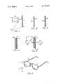
- FIG. 1 illustrates a holographic technique for forming the substrate surface relief pattern
- FIG. 2 is a cross-sectional view of a substrate with a surface relief pattern formed according to the technique illustrated in FIG. 1;
- FIG. 3 illustrates in cross-sectional view the substrate of FIG. 2 with a thin layer of material added to its surface relief pattern
- FIG. 4 illustrates in cross-section a three layer composite optical element according to the present invention
- FIG. 5 shows the optical characteristics of the resulting composite structure of FIG. 4.
- FIG. 6 shows one application of the optical element formed in the manner illustrated in FIGS. 1 through 5.
- a holographic technique for forming a surface relief pattern that reflects object images.
- Other known techniques for forming a surface relief pattern may alternatively be employed, but a holographic method has many advantages including that of simplicity and flexibility. It is the only practical method to form images of objects in the reflected light beam from the composite optical element to be formed.
- a holographic detecting film 11 is utilized in the method shown in FIG. 1 to record information of an object 13.
- a reference beam 17 of coherent radiation is also directed against the detector 11 at a finite angle with the object modified beam 15. it is also possible to bring in the reference beam from the side of the detecting film opposite to that shown in FIG. 1.
- This method is known as "back beam” holography.
- the radiation illuminating the object 13 and the reference beam 17 are coherent with each other, usually derived from the same coherent light source which is typically a laser.
- the object 13 may be diffusely reflective, in which case the object beam 15 is reflected therefrom, or may be a non-diffuse transparency, in which case the object illuminating beam is passed through the transparency onto the holographic detector 11.
- the detector 11 receives a pattern of light interference fringes to be recorded on it. These fringes are formed by the interference of the reference beam 17 and the object modified beam 15. For the purposes of the present invention, it is desired that the intensity variations of this interference pattern be recorded as surface variations on one surface of a substrate 19 as illustrated in FIG. 2. It is desired that this substrate 19 be substantially optically transparent over its surface but that a surface relief pattern 21 contain information of the object 13 for later reconstruction. Standard techniques of surface relief holography may be employed, such techniques utilizing for the detector 11 photoresist material, ordinary silver halide photographic film that is either bleached or etched to form a surface relief pattern, or a thermoplastic material, as examples.
- the substrate 19 with the surface relief 21 is preferably one of mass produced substrates from a master hologram made from the detector 11. Multiple copies of the surface relief hologram 19 may be copied according to known optical techniques from a master hologram 11, or multiple copies of the hologram 19 may be made by an embossing process from a metal master that is constructed directly from the master hologram 11.
- the holograms are made of an object 13. But for certain applications, it may be unnecessary or undesirable to record a specific object image. It may be enough to interfere with the reference beam 17 of FIG. 1, a plane wave or some other beam with its curvature optically controlled in place of the object modified beam 15.
- the results will be a hologram that reconstructs, when properly illuminated, a light pattern depending upon the curvature of the two interferring beams.
- Each surface relief hologram substrate 19 is coated with a thin layer 23 of material having a uniform thickness.
- the layer 23 is "thin" in relation to the thickness of the substrate 19 and is made to conform closely to the surface variations 21 of the substrate 19.
- the next manufacturing step for each article is to apply a coating 25 over the thin layer 23 in order to form a composite structure of substantially uniform thickness.
- the coating 25 is partially optically transparent.
- the indices of refraction for each of the substrate 19 and the coating layer 25 are made to be substantially equal in order to eliminate the effect on light transmitted through the structure of the surface relief 21.
- the surface relief 21 is desired to affect light reflected from the structure.
- the thin intermediate layer 23 is provided for that purpose.
- the layer 23 is a metal that is applied to the substrate 19 by vapor deposition or other known processes.
- Existing sunglasses use such a metalizing process in order to reflect a portion of incident light thereon and to allow another portion of incident light to pass through to the wearer's eyes. Of course, existing sunglasses reflect light as would a mirror and do not form any light pattern or object image as is possible with the structure according to the present invention.
- Aluminum is one material that may form the layer 23.
- the thickness of the layer 23 controls the amount of light that is allowed to pass through the composite structure. It is desired that at least 5% of incident light be reflected by the layer 23 while the remainder of the intensity of incident light be allowed to pass through the structure.
- the layer 23 may be of a substantially transparent material having an index of refraction that is substantially different from the indices of refraction of the substrate 19 and the coating layer 25. The result is an optical interface which reflects light.
- the index of refraction of the layer 23 should differ from that of the layers 19 and 25 by more than 3%.
- the recorded surface relief 21, as followed by the reflective coating 23, alters the phase of the reflected light beam 29 in order to form the image 13' therein, according to known holographic principles.
- the structure is made so that there is no variation in that phase caused by the surface relief pattern 21 to the component of light 27 that is transmitted through the structure.
- the element made according to FIGS. 1 through 5 has application for shading windows or for sunglasses since the transmitted light will be unaffected by the techniques used to obtain a light pattern or image in the reflected light beam.
- an element 33 as shown in FIG. 5 is held in ordinary eye glass frames 35.
- another element 37 constructed in the same manner is also held by the glass frames 35.
- the image or light pattern reconstructed upon reflection from the element 37 may be made to be the same as that of the element 33 or may be something different.
Abstract
Description
Claims (13)
Priority Applications (1)
| Application Number | Priority Date | Filing Date | Title |
|---|---|---|---|
| US06/073,511 US4315665A (en) | 1979-09-07 | 1979-09-07 | Composite optical element having controllable light transmission and reflection characteristics |
Applications Claiming Priority (1)
| Application Number | Priority Date | Filing Date | Title |
|---|---|---|---|
| US06/073,511 US4315665A (en) | 1979-09-07 | 1979-09-07 | Composite optical element having controllable light transmission and reflection characteristics |
Publications (1)
| Publication Number | Publication Date |
|---|---|
| US4315665A true US4315665A (en) | 1982-02-16 |
Family
ID=22114124
Family Applications (1)
| Application Number | Title | Priority Date | Filing Date |
|---|---|---|---|
| US06/073,511 Expired - Lifetime US4315665A (en) | 1979-09-07 | 1979-09-07 | Composite optical element having controllable light transmission and reflection characteristics |
Country Status (1)
| Country | Link |
|---|---|
| US (1) | US4315665A (en) |
Cited By (71)
| Publication number | Priority date | Publication date | Assignee | Title |
|---|---|---|---|---|
| US4547141A (en) * | 1984-07-05 | 1985-10-15 | Alpha Foils Inc. | Apparatus for embossing holograms on metalized thermoplastic films |
| EP0201323A2 (en) * | 1985-05-07 | 1986-11-12 | Dai Nippon Insatsu Kabushiki Kaisha | Article incorporating a transparent hologramm |
| JPS61272773A (en) * | 1986-01-20 | 1986-12-03 | Dainippon Printing Co Ltd | Transpparent hologram |
| JPS61272772A (en) * | 1985-05-28 | 1986-12-03 | Dainippon Printing Co Ltd | Transparent hologram formed body |
| JPS61292181A (en) * | 1986-03-11 | 1986-12-22 | Dainippon Printing Co Ltd | Transparent hologram transfer sheet |
| JPS6264638A (en) * | 1985-09-10 | 1987-03-23 | サン−ゴバン・ヴイトラ−ジユ | Front glass with reflector reflecting optical signal in visual field of driver |
| JPS62131284A (en) * | 1985-12-02 | 1987-06-13 | Dainippon Printing Co Ltd | Transparent hologram seal |
| JPS62160481A (en) * | 1986-01-09 | 1987-07-16 | Dainippon Printing Co Ltd | Transparent formed body with transparent type hologram |
| JPS62143989U (en) * | 1986-03-06 | 1987-09-10 | ||
| JPS62191465U (en) * | 1986-05-28 | 1987-12-05 | ||
| JPS6324678A (en) * | 1986-07-17 | 1988-02-02 | Dainippon Printing Co Ltd | Solar battery and electrical product using solar battery |
| WO1988001403A1 (en) * | 1986-08-15 | 1988-02-25 | Brian Hewitt | Composite holographic elements |
| JPS63143580A (en) * | 1986-12-05 | 1988-06-15 | Nissha Printing Co Ltd | Hologram label |
| JPS63143579A (en) * | 1986-12-05 | 1988-06-15 | Nissha Printing Co Ltd | Hologram transferring material |
| JPS63143581A (en) * | 1986-12-05 | 1988-06-15 | Nissha Printing Co Ltd | Hologram molded article |
| WO1988005176A1 (en) * | 1987-01-06 | 1988-07-14 | Hughes Aircraft Company | A holographic display panel for a vehicle windshield |
| WO1988005183A1 (en) * | 1987-01-06 | 1988-07-14 | Hughes Aircraft Company | Holographic indicator for determining vehicle perimeter location |
| US5073009A (en) * | 1989-06-07 | 1991-12-17 | Theoretical Optics, Inc. | Laminated beam splitting optical system with reflective medium |
| US5083850A (en) * | 1989-08-29 | 1992-01-28 | American Bank Note Holographics, Inc. | Technique of forming a separate information bearing printed pattern on replicas of a hologram or other surface relief diffraction pattern |
| US5085514A (en) * | 1989-08-29 | 1992-02-04 | American Bank Note Holographics, Inc. | Technique of forming a separate information bearing printed pattern on replicas of a hologram or other surface relief diffraction pattern |
| US5087510A (en) * | 1990-03-22 | 1992-02-11 | Monsanto Company | Electrolessly deposited metal holograms |
| US5099360A (en) * | 1989-06-07 | 1992-03-24 | Theoretical Optics, Inc. | Laminated beam splitting optical system with reflective medium |
| EP0521296A1 (en) * | 1991-05-31 | 1993-01-07 | Hughes Aircraft Company | Protected photosensitive recording films |
| WO1993015429A1 (en) * | 1989-06-07 | 1993-08-05 | Theoretical Optics, Inc. | Laminated beam splitting optical system with reflective medium |
| JPH0615067U (en) * | 1993-05-21 | 1994-02-25 | 大日本印刷株式会社 | Relief hologram |
| US5296949A (en) * | 1992-04-23 | 1994-03-22 | Flexcon Company Inc. | Optical authentication device |
| JPH0622864Y2 (en) | 1986-04-21 | 1994-06-15 | 大日本印刷株式会社 | Hologram transfer sheet |
| JPH0641262Y2 (en) | 1986-04-22 | 1994-10-26 | 大日本印刷株式会社 | Transparent hologram display |
| JPH06314057A (en) * | 1993-11-05 | 1994-11-08 | Dainippon Printing Co Ltd | Transparent hologram |
| JPH075798A (en) * | 1994-01-27 | 1995-01-10 | Dainippon Printing Co Ltd | Transparent type hologram |
| EP0634709A1 (en) * | 1987-08-10 | 1995-01-18 | Polaroid Corporation | Improvements relating to holograms and diffraction gratings |
| JPH07168516A (en) * | 1994-08-23 | 1995-07-04 | Dainippon Printing Co Ltd | Transparent type hologram |
| JPH0762784B2 (en) | 1985-05-07 | 1995-07-05 | 大日本印刷株式会社 | Transparent hologram |
| US5432623A (en) * | 1993-09-27 | 1995-07-11 | Egan; Michael S. | Optical lens incorporating an integral hologram |
| US5464710A (en) * | 1993-12-10 | 1995-11-07 | Deposition Technologies, Inc. | Enhancement of optically variable images |
| WO1996026461A1 (en) * | 1995-02-22 | 1996-08-29 | Polaroid Corporation | Eye-covering article bearing decorative reflection hologram |
| US5591527A (en) * | 1994-11-02 | 1997-01-07 | Minnesota Mining And Manufacturing Company | Optical security articles and methods for making same |
| EP0810461A1 (en) * | 1995-02-16 | 1997-12-03 | Emin Khachikovich Gulanyan | Lenses for holographic spectacles |
| US5838466A (en) * | 1996-12-13 | 1998-11-17 | Printpack Illinois, Inc. | Hidden Holograms and uses thereof |
| JP2840825B2 (en) | 1996-06-25 | 1998-12-24 | 大日本印刷株式会社 | Copy protection media |
| US5892600A (en) * | 1996-12-27 | 1999-04-06 | Kuo; Wei-Wu Alex | Spectacle lens structure with a planar reflective outer surface |
| EP1081530A1 (en) * | 1998-04-21 | 2001-03-07 | Tasr Limited | Lenses for holographic glasses and variants |
| US6224206B1 (en) * | 2000-02-08 | 2001-05-01 | Robert E. Schwartz | Fashion eyeglasses and sunglasses |
| US6231183B1 (en) | 1999-07-06 | 2001-05-15 | Stephen M. Dillon | Optical lens structure and method of fabrication thereof |
| US6288842B1 (en) | 2000-02-22 | 2001-09-11 | 3M Innovative Properties | Sheeting with composite image that floats |
| US20050195598A1 (en) * | 2003-02-07 | 2005-09-08 | Dancs Imre J. | Projecting light and images from a device |
| US20050199724A1 (en) * | 2004-03-01 | 2005-09-15 | Allen Lubow | Diffractive optical variable image including barcode |
| US20050273434A1 (en) * | 2004-04-18 | 2005-12-08 | Allen Lubow | System and method for managing security in a supply chain |
| US20060119876A1 (en) * | 2004-12-02 | 2006-06-08 | 3M Innovative Properties Company | System for reading and authenticating a composite image in a sheeting |
| US7068434B2 (en) | 2000-02-22 | 2006-06-27 | 3M Innovative Properties Company | Sheeting with composite image that floats |
| US20060221594A1 (en) * | 2005-03-31 | 2006-10-05 | Thuot Rann Raechell M | Multi-clarity lenses |
| US20060219962A1 (en) * | 2005-03-31 | 2006-10-05 | Dancs Imre J | System for detecting a container or contents of the container |
| US20060222347A1 (en) * | 2005-03-31 | 2006-10-05 | Wefler Mark E | Bottle eject mechanism |
| US20060262411A1 (en) * | 2000-02-22 | 2006-11-23 | 3M Innovative Properties Company | Sheeting with composite image that floats |
| US20070081254A1 (en) * | 2005-10-11 | 2007-04-12 | 3M Innovative Properties Company | Methods of forming sheeting with a composite image that floats and sheeting with a composite image that floats |
| US20070163158A1 (en) * | 2006-01-17 | 2007-07-19 | Bentz William G | Shields and billboards |
| US20080024872A1 (en) * | 2006-07-28 | 2008-01-31 | 3M Innovative Properties Company | Microlens sheeting with floating image using a shape memory material |
| US20080030675A1 (en) * | 2006-08-07 | 2008-02-07 | Dillon Stephen M | Uniform diffuse omni-directional reflecting lens |
| US20080130126A1 (en) * | 2006-12-04 | 2008-06-05 | 3M Innovative Properties Company | User interface including composite images that float |
| US7687744B2 (en) | 2002-05-13 | 2010-03-30 | S.C. Johnson & Son, Inc. | Coordinated emission of fragrance, light, and sound |
| US20100103528A1 (en) * | 2008-10-23 | 2010-04-29 | Endle James P | Methods of forming sheeting with composite images that float and sheeting with composite images that float |
| US20100103527A1 (en) * | 2008-10-23 | 2010-04-29 | 3M Innovative Properties Company | Methods of forming sheeting with composite images that float and sheeting with composite images that float |
| US20100316959A1 (en) * | 2007-11-27 | 2010-12-16 | Gates Brian J | Methods for forming sheeting with a composite image that floats and a master tooling |
| US7932482B2 (en) | 2003-02-07 | 2011-04-26 | S.C. Johnson & Son, Inc. | Diffuser with light emitting diode nightlight |
| US20110198781A1 (en) * | 2006-07-28 | 2011-08-18 | 3M Innovative Properties Company | Methods for changing the shape of a surface of a shape memory polymer article |
| US8459807B2 (en) | 2007-07-11 | 2013-06-11 | 3M Innovative Properties Company | Sheeting with composite image that floats |
| US20130308217A1 (en) * | 2011-01-18 | 2013-11-21 | Josef Schauer | Transparent disk with mirrored surface |
| EP2816378A4 (en) * | 2012-02-17 | 2015-09-23 | Hoya Lens Mfg Philippines Inc | Optical member and method for manufacturing optical member |
| US9244201B2 (en) | 2012-04-14 | 2016-01-26 | Stephen M. Dillon | Diffuse reflecting optical construction |
| US10279069B2 (en) | 2006-07-28 | 2019-05-07 | 3M Innovative Properties Company | Shape memory polymer articles with a microstructured surface |
| US10698139B2 (en) | 2016-10-03 | 2020-06-30 | Stephen M. Dillon | Diffuse reflecting optical construction |
Citations (6)
| Publication number | Priority date | Publication date | Assignee | Title |
|---|---|---|---|---|
| US3552853A (en) * | 1968-07-01 | 1971-01-05 | Chain Lakes Res Assoc | Hologramic identification system |
| US3628854A (en) * | 1969-12-08 | 1971-12-21 | Optical Sciences Group Inc | Flexible fresnel refracting membrane adhered to ophthalmic lens |
| US3633988A (en) * | 1970-07-10 | 1972-01-11 | Us Navy | Helmet-mounted holographic aiming sight |
| US3703407A (en) * | 1970-12-15 | 1972-11-21 | Rca Corp | Relief phase holograms |
| US3945825A (en) * | 1974-05-22 | 1976-03-23 | Rca Corporation | Method for producing width-modulated surface relief patterns |
| US4014602A (en) * | 1975-01-16 | 1977-03-29 | Siemens Aktiengesellschaft | Identification card having a hologram superimposed on printed data |
-
1979
- 1979-09-07 US US06/073,511 patent/US4315665A/en not_active Expired - Lifetime
Patent Citations (6)
| Publication number | Priority date | Publication date | Assignee | Title |
|---|---|---|---|---|
| US3552853A (en) * | 1968-07-01 | 1971-01-05 | Chain Lakes Res Assoc | Hologramic identification system |
| US3628854A (en) * | 1969-12-08 | 1971-12-21 | Optical Sciences Group Inc | Flexible fresnel refracting membrane adhered to ophthalmic lens |
| US3633988A (en) * | 1970-07-10 | 1972-01-11 | Us Navy | Helmet-mounted holographic aiming sight |
| US3703407A (en) * | 1970-12-15 | 1972-11-21 | Rca Corp | Relief phase holograms |
| US3945825A (en) * | 1974-05-22 | 1976-03-23 | Rca Corporation | Method for producing width-modulated surface relief patterns |
| US4014602A (en) * | 1975-01-16 | 1977-03-29 | Siemens Aktiengesellschaft | Identification card having a hologram superimposed on printed data |
Cited By (113)
| Publication number | Priority date | Publication date | Assignee | Title |
|---|---|---|---|---|
| US4547141A (en) * | 1984-07-05 | 1985-10-15 | Alpha Foils Inc. | Apparatus for embossing holograms on metalized thermoplastic films |
| JPH0762784B2 (en) | 1985-05-07 | 1995-07-05 | 大日本印刷株式会社 | Transparent hologram |
| EP0201323A2 (en) * | 1985-05-07 | 1986-11-12 | Dai Nippon Insatsu Kabushiki Kaisha | Article incorporating a transparent hologramm |
| EP0201323A3 (en) * | 1985-05-07 | 1990-06-13 | Dai Nippon Insatsu Kabushiki Kaisha | Transparent-type hologram |
| EP0609683A1 (en) * | 1985-05-07 | 1994-08-10 | Dai Nippon Insatsu Kabushiki Kaisha | Relief hologram and process for producing a relief hologram |
| JPS61272772A (en) * | 1985-05-28 | 1986-12-03 | Dainippon Printing Co Ltd | Transparent hologram formed body |
| JPH0679193B2 (en) | 1985-05-28 | 1994-10-05 | 大日本印刷株式会社 | Transparent hologram forming body |
| EP0216692A2 (en) * | 1985-09-10 | 1987-04-01 | Saint-Gobain Vitrage International | Windscreen having a particular reflection direction to reflect optical signals into the field of vision of the driver |
| JPS6264638A (en) * | 1985-09-10 | 1987-03-23 | サン−ゴバン・ヴイトラ−ジユ | Front glass with reflector reflecting optical signal in visual field of driver |
| EP0216692A3 (en) * | 1985-09-10 | 1988-06-08 | Saint-Gobain Vitrage | Windscreen having a particular reflection direction to reflect optical signals into the field of vision of the driver |
| JP2693756B2 (en) | 1985-09-10 | 1997-12-24 | サン−ゴバン・ヴイトラ−ジユ | "Head-up" display integrated into a vehicle with windshield |
| JPS62131284A (en) * | 1985-12-02 | 1987-06-13 | Dainippon Printing Co Ltd | Transparent hologram seal |
| JPH0646340B2 (en) | 1985-12-02 | 1994-06-15 | 大日本印刷株式会社 | Transparent hologram sticker |
| JPH0792636B2 (en) | 1986-01-09 | 1995-10-09 | 大日本印刷株式会社 | Transparent formed body with transparent hologram |
| JPS62160481A (en) * | 1986-01-09 | 1987-07-16 | Dainippon Printing Co Ltd | Transparent formed body with transparent type hologram |
| JPS61272773A (en) * | 1986-01-20 | 1986-12-03 | Dainippon Printing Co Ltd | Transpparent hologram |
| JPS62143989U (en) * | 1986-03-06 | 1987-09-10 | ||
| JPH0447748Y2 (en) * | 1986-03-06 | 1992-11-11 | ||
| JPH0587835B2 (en) * | 1986-03-11 | 1993-12-20 | Dainippon Printing Co Ltd | |
| JPS61292181A (en) * | 1986-03-11 | 1986-12-22 | Dainippon Printing Co Ltd | Transparent hologram transfer sheet |
| JPH0622864Y2 (en) | 1986-04-21 | 1994-06-15 | 大日本印刷株式会社 | Hologram transfer sheet |
| JPH0641262Y2 (en) | 1986-04-22 | 1994-10-26 | 大日本印刷株式会社 | Transparent hologram display |
| JPH0615687Y2 (en) | 1986-05-28 | 1994-04-27 | 大日本印刷株式会社 | Optical card with transparent hologram |
| JPS62191465U (en) * | 1986-05-28 | 1987-12-05 | ||
| JP2622677B2 (en) | 1986-07-17 | 1997-06-18 | 大日本印刷株式会社 | Solar cells and electrical products using solar cells |
| JPS6324678A (en) * | 1986-07-17 | 1988-02-02 | Dainippon Printing Co Ltd | Solar battery and electrical product using solar battery |
| US4840444A (en) * | 1986-08-15 | 1989-06-20 | Brian Hewitt | Composite holographic elements |
| WO1988001403A1 (en) * | 1986-08-15 | 1988-02-25 | Brian Hewitt | Composite holographic elements |
| JPS63143581A (en) * | 1986-12-05 | 1988-06-15 | Nissha Printing Co Ltd | Hologram molded article |
| JPS63143580A (en) * | 1986-12-05 | 1988-06-15 | Nissha Printing Co Ltd | Hologram label |
| JPS63143579A (en) * | 1986-12-05 | 1988-06-15 | Nissha Printing Co Ltd | Hologram transferring material |
| WO1988005176A1 (en) * | 1987-01-06 | 1988-07-14 | Hughes Aircraft Company | A holographic display panel for a vehicle windshield |
| WO1988005183A1 (en) * | 1987-01-06 | 1988-07-14 | Hughes Aircraft Company | Holographic indicator for determining vehicle perimeter location |
| EP0634710A1 (en) * | 1987-08-10 | 1995-01-18 | Polaroid Corporation | Improvements relating to holograms and diffraction gratings |
| EP0634709A1 (en) * | 1987-08-10 | 1995-01-18 | Polaroid Corporation | Improvements relating to holograms and diffraction gratings |
| US5099360A (en) * | 1989-06-07 | 1992-03-24 | Theoretical Optics, Inc. | Laminated beam splitting optical system with reflective medium |
| US5073009A (en) * | 1989-06-07 | 1991-12-17 | Theoretical Optics, Inc. | Laminated beam splitting optical system with reflective medium |
| WO1993015429A1 (en) * | 1989-06-07 | 1993-08-05 | Theoretical Optics, Inc. | Laminated beam splitting optical system with reflective medium |
| US5083850A (en) * | 1989-08-29 | 1992-01-28 | American Bank Note Holographics, Inc. | Technique of forming a separate information bearing printed pattern on replicas of a hologram or other surface relief diffraction pattern |
| US5085514A (en) * | 1989-08-29 | 1992-02-04 | American Bank Note Holographics, Inc. | Technique of forming a separate information bearing printed pattern on replicas of a hologram or other surface relief diffraction pattern |
| US5087510A (en) * | 1990-03-22 | 1992-02-11 | Monsanto Company | Electrolessly deposited metal holograms |
| EP0521296A1 (en) * | 1991-05-31 | 1993-01-07 | Hughes Aircraft Company | Protected photosensitive recording films |
| US5296949A (en) * | 1992-04-23 | 1994-03-22 | Flexcon Company Inc. | Optical authentication device |
| JP2516920Y2 (en) | 1993-05-21 | 1996-11-13 | 大日本印刷株式会社 | Relief hologram |
| JPH0615067U (en) * | 1993-05-21 | 1994-02-25 | 大日本印刷株式会社 | Relief hologram |
| US5432623A (en) * | 1993-09-27 | 1995-07-11 | Egan; Michael S. | Optical lens incorporating an integral hologram |
| JPH06314057A (en) * | 1993-11-05 | 1994-11-08 | Dainippon Printing Co Ltd | Transparent hologram |
| US5464710A (en) * | 1993-12-10 | 1995-11-07 | Deposition Technologies, Inc. | Enhancement of optically variable images |
| JPH075798A (en) * | 1994-01-27 | 1995-01-10 | Dainippon Printing Co Ltd | Transparent type hologram |
| JP2871476B2 (en) | 1994-08-23 | 1999-03-17 | 大日本印刷株式会社 | Transparent hologram |
| JPH07168516A (en) * | 1994-08-23 | 1995-07-04 | Dainippon Printing Co Ltd | Transparent type hologram |
| US5743981A (en) * | 1994-11-02 | 1998-04-28 | Minnesota Mining And Manufacturing Company | Optical security articles and methods for making same |
| US5591527A (en) * | 1994-11-02 | 1997-01-07 | Minnesota Mining And Manufacturing Company | Optical security articles and methods for making same |
| EP0810461A4 (en) * | 1995-02-16 | 1999-02-10 | Tasr Limited Gulanyan Emin Kha | Lenses for holographic spectacles |
| EP0810461A1 (en) * | 1995-02-16 | 1997-12-03 | Emin Khachikovich Gulanyan | Lenses for holographic spectacles |
| WO1996026461A1 (en) * | 1995-02-22 | 1996-08-29 | Polaroid Corporation | Eye-covering article bearing decorative reflection hologram |
| US6020983A (en) * | 1995-02-22 | 2000-02-01 | Polaroid Corporation | Method for the manufacture of eye-covering articles bearing decorative reflection holograms |
| JP2840825B2 (en) | 1996-06-25 | 1998-12-24 | 大日本印刷株式会社 | Copy protection media |
| US5838466A (en) * | 1996-12-13 | 1998-11-17 | Printpack Illinois, Inc. | Hidden Holograms and uses thereof |
| US5892600A (en) * | 1996-12-27 | 1999-04-06 | Kuo; Wei-Wu Alex | Spectacle lens structure with a planar reflective outer surface |
| EP1081530A4 (en) * | 1998-04-21 | 2001-10-24 | Tasr Ltd | Lenses for holographic glasses and variants |
| EP1081530A1 (en) * | 1998-04-21 | 2001-03-07 | Tasr Limited | Lenses for holographic glasses and variants |
| US6231183B1 (en) | 1999-07-06 | 2001-05-15 | Stephen M. Dillon | Optical lens structure and method of fabrication thereof |
| US20020018177A1 (en) * | 1999-07-06 | 2002-02-14 | Dillon Stephen M. | Optical lens structure and method of fabrication thereof |
| US6719928B2 (en) * | 1999-07-06 | 2004-04-13 | Stephen M. Dillon | Optical lens structure and method of fabrication thereof |
| US6224206B1 (en) * | 2000-02-08 | 2001-05-01 | Robert E. Schwartz | Fashion eyeglasses and sunglasses |
| US20080118862A1 (en) * | 2000-02-22 | 2008-05-22 | 3M Innovative Properties Company | Sheeting with composite image that floats |
| US6288842B1 (en) | 2000-02-22 | 2001-09-11 | 3M Innovative Properties | Sheeting with composite image that floats |
| US20060262411A1 (en) * | 2000-02-22 | 2006-11-23 | 3M Innovative Properties Company | Sheeting with composite image that floats |
| US8057980B2 (en) | 2000-02-22 | 2011-11-15 | Dunn Douglas S | Sheeting with composite image that floats |
| US7336422B2 (en) | 2000-02-22 | 2008-02-26 | 3M Innovative Properties Company | Sheeting with composite image that floats |
| US7068434B2 (en) | 2000-02-22 | 2006-06-27 | 3M Innovative Properties Company | Sheeting with composite image that floats |
| US7687744B2 (en) | 2002-05-13 | 2010-03-30 | S.C. Johnson & Son, Inc. | Coordinated emission of fragrance, light, and sound |
| US20050195598A1 (en) * | 2003-02-07 | 2005-09-08 | Dancs Imre J. | Projecting light and images from a device |
| US7932482B2 (en) | 2003-02-07 | 2011-04-26 | S.C. Johnson & Son, Inc. | Diffuser with light emitting diode nightlight |
| US20050199724A1 (en) * | 2004-03-01 | 2005-09-15 | Allen Lubow | Diffractive optical variable image including barcode |
| US20050273434A1 (en) * | 2004-04-18 | 2005-12-08 | Allen Lubow | System and method for managing security in a supply chain |
| US7616332B2 (en) | 2004-12-02 | 2009-11-10 | 3M Innovative Properties Company | System for reading and authenticating a composite image in a sheeting |
| US8072626B2 (en) | 2004-12-02 | 2011-12-06 | 3M Innovative Properties Company | System for reading and authenticating a composite image in a sheeting |
| US20060119876A1 (en) * | 2004-12-02 | 2006-06-08 | 3M Innovative Properties Company | System for reading and authenticating a composite image in a sheeting |
| US7643734B2 (en) | 2005-03-31 | 2010-01-05 | S.C. Johnson & Son, Inc. | Bottle eject mechanism |
| US7281811B2 (en) | 2005-03-31 | 2007-10-16 | S. C. Johnson & Son, Inc. | Multi-clarity lenses |
| US20060222347A1 (en) * | 2005-03-31 | 2006-10-05 | Wefler Mark E | Bottle eject mechanism |
| US20060219962A1 (en) * | 2005-03-31 | 2006-10-05 | Dancs Imre J | System for detecting a container or contents of the container |
| US7589340B2 (en) | 2005-03-31 | 2009-09-15 | S.C. Johnson & Son, Inc. | System for detecting a container or contents of the container |
| US20060221594A1 (en) * | 2005-03-31 | 2006-10-05 | Thuot Rann Raechell M | Multi-clarity lenses |
| US20090278554A1 (en) * | 2005-03-31 | 2009-11-12 | Dancs Imre J | System for Detecting a Container or Contents of the Container |
| US7981499B2 (en) | 2005-10-11 | 2011-07-19 | 3M Innovative Properties Company | Methods of forming sheeting with a composite image that floats and sheeting with a composite image that floats |
| US20070081254A1 (en) * | 2005-10-11 | 2007-04-12 | 3M Innovative Properties Company | Methods of forming sheeting with a composite image that floats and sheeting with a composite image that floats |
| US20070163158A1 (en) * | 2006-01-17 | 2007-07-19 | Bentz William G | Shields and billboards |
| US10279069B2 (en) | 2006-07-28 | 2019-05-07 | 3M Innovative Properties Company | Shape memory polymer articles with a microstructured surface |
| US7586685B2 (en) | 2006-07-28 | 2009-09-08 | Dunn Douglas S | Microlens sheeting with floating image using a shape memory material |
| US20080024872A1 (en) * | 2006-07-28 | 2008-01-31 | 3M Innovative Properties Company | Microlens sheeting with floating image using a shape memory material |
| US8236226B2 (en) | 2006-07-28 | 2012-08-07 | 3M Innovative Properties Company | Methods for changing the shape of a surface of a shape memory polymer article |
| US20110198781A1 (en) * | 2006-07-28 | 2011-08-18 | 3M Innovative Properties Company | Methods for changing the shape of a surface of a shape memory polymer article |
| US7443608B2 (en) | 2006-08-07 | 2008-10-28 | Dillon Stephen M | Uniform diffuse omni-directional reflecting lens |
| EP1887414A1 (en) * | 2006-08-07 | 2008-02-13 | Stephen M. Dillon | Uniform diffuse omni-directional reflecting lens |
| US20080030675A1 (en) * | 2006-08-07 | 2008-02-07 | Dillon Stephen M | Uniform diffuse omni-directional reflecting lens |
| US7800825B2 (en) | 2006-12-04 | 2010-09-21 | 3M Innovative Properties Company | User interface including composite images that float |
| US20080130126A1 (en) * | 2006-12-04 | 2008-06-05 | 3M Innovative Properties Company | User interface including composite images that float |
| US8459807B2 (en) | 2007-07-11 | 2013-06-11 | 3M Innovative Properties Company | Sheeting with composite image that floats |
| US8586285B2 (en) | 2007-11-27 | 2013-11-19 | 3M Innovative Properties Company | Methods for forming sheeting with a composite image that floats and a master tooling |
| US20100316959A1 (en) * | 2007-11-27 | 2010-12-16 | Gates Brian J | Methods for forming sheeting with a composite image that floats and a master tooling |
| US20100103528A1 (en) * | 2008-10-23 | 2010-04-29 | Endle James P | Methods of forming sheeting with composite images that float and sheeting with composite images that float |
| US8111463B2 (en) | 2008-10-23 | 2012-02-07 | 3M Innovative Properties Company | Methods of forming sheeting with composite images that float and sheeting with composite images that float |
| US8537470B2 (en) | 2008-10-23 | 2013-09-17 | 3M Innovative Properties Company | Methods of forming sheeting with composite images that float and sheeting with composite images that float |
| US20100103527A1 (en) * | 2008-10-23 | 2010-04-29 | 3M Innovative Properties Company | Methods of forming sheeting with composite images that float and sheeting with composite images that float |
| US7995278B2 (en) | 2008-10-23 | 2011-08-09 | 3M Innovative Properties Company | Methods of forming sheeting with composite images that float and sheeting with composite images that float |
| US20130308217A1 (en) * | 2011-01-18 | 2013-11-21 | Josef Schauer | Transparent disk with mirrored surface |
| US9494806B2 (en) * | 2011-01-18 | 2016-11-15 | Josef Schauer | Transparent disk with mirrored surface |
| EP2816378A4 (en) * | 2012-02-17 | 2015-09-23 | Hoya Lens Mfg Philippines Inc | Optical member and method for manufacturing optical member |
| US9244201B2 (en) | 2012-04-14 | 2016-01-26 | Stephen M. Dillon | Diffuse reflecting optical construction |
| US10698139B2 (en) | 2016-10-03 | 2020-06-30 | Stephen M. Dillon | Diffuse reflecting optical construction |
Similar Documents
| Publication | Publication Date | Title |
|---|---|---|
| US4315665A (en) | Composite optical element having controllable light transmission and reflection characteristics | |
| US4840444A (en) | Composite holographic elements | |
| US4960311A (en) | Holographic exposure system for computer generated holograms | |
| US6020983A (en) | Method for the manufacture of eye-covering articles bearing decorative reflection holograms | |
| US5499118A (en) | System for copying multiple holograms | |
| US5103323A (en) | Multi-layer holographic notch filter | |
| EP0046218B1 (en) | Method and apparatus for production of holographic optical elements | |
| KR950014879B1 (en) | Holographic stack manufacturing method | |
| US5330264A (en) | Method and apparatus for copying and manufacturing hologram plate | |
| EP0043993B1 (en) | Method and assembly for holographic exposure | |
| US4815800A (en) | Flare reduction in holograms | |
| US4412719A (en) | Method and article having predetermined net reflectance characteristics | |
| US4802719A (en) | Infra-red laser shield | |
| US3623798A (en) | Blazed hologram fabrication | |
| US4984856A (en) | Holographic exposure system to reduce spurious hologram noise | |
| GB2226421A (en) | Hologram sheet attached to transparent plate | |
| JPH05232318A (en) | Reflection type hologram scale | |
| JPH0640236B2 (en) | Holographic Efficiency Improvement Method | |
| JPS60122983A (en) | Copying method of hologram | |
| RU2128355C1 (en) | Lenses for holographic spectacles | |
| JPH0713475A (en) | Production of hologram | |
| JP3063274B2 (en) | Method of manufacturing holographic optical element | |
| KR100369784B1 (en) | Sunglasses having decorative reflection hologram and method for manufacturing the same | |
| GB2246645A (en) | A holographic element comprising holographic material on a mirror on a substrate | |
| WO2011046822A1 (en) | Hologram and associated methods of fabrication thereof and use in security/authentication applications |
Legal Events
| Date | Code | Title | Description |
|---|---|---|---|
| STCF | Information on status: patent grant |
Free format text: PATENTED CASE |
|
| AS | Assignment |
Owner name: MELLON BANK, N.A. A NATIONAL BANKING ASSOCIATION O Free format text: ASSIGNMENT OF ASSIGNORS INTEREST. SUBJECT TO AGREEMENT RECITED;ASSIGNORS:INTERNATIONAL BANKNOTE COMPANY, INC.;AMERICAN BANK NOTE COMPANY;ABN DEVELOPMENT CORPORATION;AND OTHERS;REEL/FRAME:004381/0272 Effective date: 19841130 |
|
| AS | Assignment |
Owner name: AMERICAN BANK NOTE COMPANY Free format text: RELEASED BY SECURED PARTY;ASSIGNOR:MELLON BANK, N.A.;REEL/FRAME:005029/0228 Effective date: 19880128 Owner name: EIDETIC IMAGES, INC. Free format text: RELEASED BY SECURED PARTY;ASSIGNOR:MELLON, N.A.;REEL/FRAME:005029/0245 Effective date: 19880128 |
|
| AS | Assignment |
Owner name: AMERICAN BANK NOTE HOLOGRAPHICS, INC., NEW YORK Free format text: MERGER;ASSIGNOR:EIDETIC IMAGES, INC.;REEL/FRAME:009386/0067 Effective date: 19980720 |
|
| AS | Assignment |
Owner name: CHASE MANHATTAN BANK, THE, AS AGENT,, NEW YORK Free format text: SECURITY AGREEMENT;ASSIGNOR:AMERICAN BANK NOTE HOLOGRAPHICS, INC.;REEL/FRAME:009396/0982 Effective date: 19980720 |
|
| AS | Assignment |
Owner name: AMERICAN BANK NOTE HOLOGRAPHICS, NEW YORK Free format text: RLEASE OF LIEN ON PATENTS;ASSIGNOR:CHASE MANHATTAN BANK THE, AS AGENT;REEL/FRAME:010299/0047 Effective date: 19990929 |
|
| AS | Assignment |
Owner name: FOOTHILL CAPITAL CORPORATION, CALIFORNIA Free format text: SECURITY INTEREST;ASSIGNOR:AMERICAN BANK NOTE HOLOGRAPHICS;REEL/FRAME:010299/0249 Effective date: 19990929 |
|
| AS | Assignment |
Owner name: AMERICAN BANK NOTE HOLOGRAPHICS, INC., NEW JERSEY Free format text: RELEASE OF SECURITY INTEREST WITH SCHEDULE A;ASSIGNOR:WELLS FARGO FOOTHILL (F/K/A FOOTHILL CAPITAL CORPORATION);REEL/FRAME:020218/0067 Effective date: 20071205 |