US3681184A - Nonwoven fabrics comprising bamboo,diamond and the like patterns - Google Patents
Nonwoven fabrics comprising bamboo,diamond and the like patterns Download PDFInfo
- Publication number
- US3681184A US3681184A US3681184DA US3681184A US 3681184 A US3681184 A US 3681184A US 3681184D A US3681184D A US 3681184DA US 3681184 A US3681184 A US 3681184A
- Authority
- US
- United States
- Prior art keywords
- fabric
- bundles
- yarn
- fiber
- fibers
- Prior art date
- Legal status (The legal status is an assumption and is not a legal conclusion. Google has not performed a legal analysis and makes no representation as to the accuracy of the status listed.)
- Expired - Lifetime
Links
Images


Classifications
-
- D—TEXTILES; PAPER
- D04—BRAIDING; LACE-MAKING; KNITTING; TRIMMINGS; NON-WOVEN FABRICS
- D04H—MAKING TEXTILE FABRICS, e.g. FROM FIBRES OR FILAMENTARY MATERIAL; FABRICS MADE BY SUCH PROCESSES OR APPARATUS, e.g. FELTS, NON-WOVEN FABRICS; COTTON-WOOL; WADDING ; NON-WOVEN FABRICS FROM STAPLE FIBRES, FILAMENTS OR YARNS, BONDED WITH AT LEAST ONE WEB-LIKE MATERIAL DURING THEIR CONSOLIDATION
- D04H1/00—Non-woven fabrics formed wholly or mainly of staple fibres or like relatively short fibres
- D04H1/70—Non-woven fabrics formed wholly or mainly of staple fibres or like relatively short fibres characterised by the method of forming fleeces or layers, e.g. reorientation of fibres
- D04H1/74—Non-woven fabrics formed wholly or mainly of staple fibres or like relatively short fibres characterised by the method of forming fleeces or layers, e.g. reorientation of fibres the fibres being orientated, e.g. in parallel (anisotropic fleeces)
-
- Y—GENERAL TAGGING OF NEW TECHNOLOGICAL DEVELOPMENTS; GENERAL TAGGING OF CROSS-SECTIONAL TECHNOLOGIES SPANNING OVER SEVERAL SECTIONS OF THE IPC; TECHNICAL SUBJECTS COVERED BY FORMER USPC CROSS-REFERENCE ART COLLECTIONS [XRACs] AND DIGESTS
- Y10—TECHNICAL SUBJECTS COVERED BY FORMER USPC
- Y10T—TECHNICAL SUBJECTS COVERED BY FORMER US CLASSIFICATION
- Y10T428/00—Stock material or miscellaneous articles
- Y10T428/24—Structurally defined web or sheet [e.g., overall dimension, etc.]
- Y10T428/24273—Structurally defined web or sheet [e.g., overall dimension, etc.] including aperture
- Y10T428/24298—Noncircular aperture [e.g., slit, diamond, rectangular, etc.]
- Y10T428/24306—Diamond or hexagonal
-
- Y—GENERAL TAGGING OF NEW TECHNOLOGICAL DEVELOPMENTS; GENERAL TAGGING OF CROSS-SECTIONAL TECHNOLOGIES SPANNING OVER SEVERAL SECTIONS OF THE IPC; TECHNICAL SUBJECTS COVERED BY FORMER USPC CROSS-REFERENCE ART COLLECTIONS [XRACs] AND DIGESTS
- Y10—TECHNICAL SUBJECTS COVERED BY FORMER USPC
- Y10T—TECHNICAL SUBJECTS COVERED BY FORMER US CLASSIFICATION
- Y10T428/00—Stock material or miscellaneous articles
- Y10T428/24—Structurally defined web or sheet [e.g., overall dimension, etc.]
- Y10T428/24479—Structurally defined web or sheet [e.g., overall dimension, etc.] including variation in thickness
-
- Y—GENERAL TAGGING OF NEW TECHNOLOGICAL DEVELOPMENTS; GENERAL TAGGING OF CROSS-SECTIONAL TECHNOLOGIES SPANNING OVER SEVERAL SECTIONS OF THE IPC; TECHNICAL SUBJECTS COVERED BY FORMER USPC CROSS-REFERENCE ART COLLECTIONS [XRACs] AND DIGESTS
- Y10—TECHNICAL SUBJECTS COVERED BY FORMER USPC
- Y10T—TECHNICAL SUBJECTS COVERED BY FORMER US CLASSIFICATION
- Y10T428/00—Stock material or miscellaneous articles
- Y10T428/24—Structurally defined web or sheet [e.g., overall dimension, etc.]
- Y10T428/24802—Discontinuous or differential coating, impregnation or bond [e.g., artwork, printing, retouched photograph, etc.]
-
- Y—GENERAL TAGGING OF NEW TECHNOLOGICAL DEVELOPMENTS; GENERAL TAGGING OF CROSS-SECTIONAL TECHNOLOGIES SPANNING OVER SEVERAL SECTIONS OF THE IPC; TECHNICAL SUBJECTS COVERED BY FORMER USPC CROSS-REFERENCE ART COLLECTIONS [XRACs] AND DIGESTS
- Y10—TECHNICAL SUBJECTS COVERED BY FORMER USPC
- Y10T—TECHNICAL SUBJECTS COVERED BY FORMER US CLASSIFICATION
- Y10T428/00—Stock material or miscellaneous articles
- Y10T428/24—Structurally defined web or sheet [e.g., overall dimension, etc.]
- Y10T428/24942—Structurally defined web or sheet [e.g., overall dimension, etc.] including components having same physical characteristic in differing degree
- Y10T428/2495—Thickness [relative or absolute]
-
- Y—GENERAL TAGGING OF NEW TECHNOLOGICAL DEVELOPMENTS; GENERAL TAGGING OF CROSS-SECTIONAL TECHNOLOGIES SPANNING OVER SEVERAL SECTIONS OF THE IPC; TECHNICAL SUBJECTS COVERED BY FORMER USPC CROSS-REFERENCE ART COLLECTIONS [XRACs] AND DIGESTS
- Y10—TECHNICAL SUBJECTS COVERED BY FORMER USPC
- Y10T—TECHNICAL SUBJECTS COVERED BY FORMER US CLASSIFICATION
- Y10T428/00—Stock material or miscellaneous articles
- Y10T428/29—Coated or structually defined flake, particle, cell, strand, strand portion, rod, filament, macroscopic fiber or mass thereof
- Y10T428/2904—Staple length fiber
-
- Y—GENERAL TAGGING OF NEW TECHNOLOGICAL DEVELOPMENTS; GENERAL TAGGING OF CROSS-SECTIONAL TECHNOLOGIES SPANNING OVER SEVERAL SECTIONS OF THE IPC; TECHNICAL SUBJECTS COVERED BY FORMER USPC CROSS-REFERENCE ART COLLECTIONS [XRACs] AND DIGESTS
- Y10—TECHNICAL SUBJECTS COVERED BY FORMER USPC
- Y10T—TECHNICAL SUBJECTS COVERED BY FORMER US CLASSIFICATION
- Y10T442/00—Fabric [woven, knitted, or nonwoven textile or cloth, etc.]
- Y10T442/60—Nonwoven fabric [i.e., nonwoven strand or fiber material]
- Y10T442/69—Autogenously bonded nonwoven fabric
Definitions
- a nonwoven fabric having a plurality of patterns of groups of ber segments that alternate and extend throughout the fabric.
- One of the patterns comprises a plurality of yarn-like bundles of ber segments that define apertures or holes or other areas of low ber density located in discontinuous portions of the fabric.
- the discontinuous portions of the fabric are 'bounded around their perimeters by a second continuous pattern of yarnlike bundles of ber segments.
- the present invention relates to nonwoven fabrics, and more particularly to patterned nonwovenv fabrics made from a layer of brous material such as a brous web wherein the individual ber elements are capable of movement under the influence of applied fluid forces.
- the rst pattern in the fabric is a pattern of yarn-like bundles of closely associated and substantially parallel ber segments that dene apertures (holes) or other areas of low ber density in discontinuous portions of the fabric.
- the second pattern is a pattern of yarn-like bundles of ber segments in continuous portions of the fabric that lie between and interconnect the discontinuous portions of the fabric.
- areas of low ber density is used in this specication and claims to include both areas in which relatively few fibers in comparison to the rest of the fabric are found and apertures (holes) that are substantially or entirely free of bers.
- Such fabrics will be hereinafter referred to as bundled rearranged nonwoven fabrics.
- Bundled rearranged nonwoven fabrics have been made commercially for many years. In most instances, these fabrics have had an overall pattern of holes or other low ber density areas throughout the fabric.
- LA method for producing bundled rearranged nonwoven fabrics is to support a loose fibrous web or layer on a permeable backing member and apply sets of opposing fluid forces to the layer while thus supported.
- the fluid by which such forces are applied passes through the brous layer over the backing member and then through the backing member to pack various groups of fibers elements and to place these elements into closer proximity and substantial parallelism to form interconnected bundles .of ber segmentsAIn accomplishing this result, the fluid forces usually are applied over the entire surface of the loose fibrous web or layer and uniformly over and through the permeable backing or support member to produce ber :bundles uniformly over the entire fabric.
- patterns can be made in the fabric by not applying fluid forces to predetermined areas of the fibrous layer thereby preventing rearrangement in these areas.
- a novel nonwoven fabric which comprises a layer of intermingled fibers with the bers arranged to dene a plurality of patterns.
- the rst pattern is located in discontinuous areas of the fabric. These discontinuous areas comprise a plurality of yarn-like bundles of fiber segments that dene apertures or holes or other areas of low ber density.
- the ber segments in each of the bundles are closely associated with other ber segments in the bundle and lie generally parallel to the longitudinal axis of the ibundle.
- the yarn-like bundles of ber segments are interconnected with other bundles at junctures by groups of fibers common to a plurality of bundles.
- the bers at said junctures are oriented in a plurality of diverse directions.
- the discontinuous portions of the fabric are bound around their perimeter by a second pattern of yarn-like bundles.
- This second pattern of yarnlike bundles is continuous throughout the fabric.
- the yarn-like bundles of the second pattern may be of a different weight than the yarn-like bundles in the first discontinuous portions of the fabric.
- the yarn-like bundles in the predetermihed continuous portions of the fabric are heavier than the yarn-like bundles in the discontinuous portions of the fabric.
- the yarn-like bundles in the continuous portions of the fabric will extend longitudinally and transverse of the fabric while in other embodiments, they may extend in various other continuous shapes throughout the fabric.
- the discontinuous portions of the fabric may have various shapes; that is, square, round, hexagonal, etc.
- my new fabric has a plurality of patterns which extend throughout the fabric, the patterns have substantial regularity and aid in providing a fabric having considerably aesthetic appeal. Furthermore, not only does my new fabric have substantial uniformity in its areas of low ber density or holes, but unexpectedly, my new fabric has uniformity in the patterns of bundles of ber segments, including both the pattern of bundles in the discontinuous portions of the fabric and the pattern of bundles which bound the perimeters of the discontinuous portions.
- the starting material is a layer of brous material whose individual bers are in mechanical engagement with one another but are capable of movement under applied fluid forces.
- the layer of brous starting material is supported in a ber rearranging zone in which ber movement in directions parallel to the plane of said brous material is permitted in response to applied fluid forces.
- Streams of rearranging fluid, preferably water, are then projected into the brous layer, in a direction perpendicular to the layer, at entry zones spaced from each other adjacent the entry side of the rearranging zone.
- Each stream of rearranging fluid entering an entry zone is passed through the initial part of the rearranging zone, as the brous starting material lies in that zone, toward two or more dispersal points lying directly opposite the entry zone and adjacent the exit side of the rearranging zone.
- rearranging fluid is deflected at each such dispersal point diagonally and downwardly, into the area immediately surrounding the dispersal point, away from the perpendicular direction at which the fiuid was first projected into the fibrous starting layer.
- This defiection of the rearranging fluid moves fiber segments lying opposite an entry zone into the area surrounding a dispersal point opposite that entry zone, and positions some of those fiber segments in yarn-like bundles ofclosely associated and substantially parallel fiber segments in areas of the fibrous starting material surrounding the entry zone.
- Other fiber segments moved by the rearranging fluid away from a dispersal point are positioned in similar yarn-like bundles in fiber accumulating zones that lie between adjacent dispersal points and are in registry with an entry zone.
- the deflected and undefiected portions of the rearranging fluid are then intermingled and passed out of the fiber rearranging zone through spaced exits at the exit side of the rearranging zone.
- the fibrous starting layer is supported on a foraminous backing means having a plurality of protuberances and troughs alternating across its surface in both the longitudinal and transverse directions, apertured forming means is positioned above the fibrous layer, and streams of rearranging fluid, preferably water, are projected through the apertures of the apertured forming means and against the fibrous starting material.
- the vertical distance between the tops of the protuberances on the backing means and the bottoms of the immediately adjacent troughs is equal to at least about three times the average diameter of the fibers in the layer of fibrous starting material.
- Each of the apertures in the apertured forming means is wide enough to span two or more of the protuberances on the backing means.
- the resulting novel nonwoven fabric displays a plurality of patterns of yarn-like bundles of fiber segments that alternate and extend throughout the fabric.
- the first of these is a pattern of yarn-like bundles of fiber segments that have been positioned in the troughs on the surface of the foraminous backing means. These yarn-like bundles at least partially define holes or other areas of low fiber density in discontinuous portions of the fabric.
- the second pattern is a pattern of yarn-like bundles arranged in accordance with the configuration of the land areas of the apertured forming means. These yarn-like bundles surround the discontinuous portions of the fabric to form a continuous pattern of yarn-like bundles in the fabric.
- the starting material used for producing the novel nonwoven fabrics of this invention may be any of the standard fibrous webs such as oriented card webs, isowebs, air-laid webs, or webs formed by liquid deposition.
- the webs may be Iformed in a single layer, or by laminating a plurality of the webs together.
- the fibers in the web may be arranged in a random manner or may be more or less oriented as in a card web.
- the individual fibers may be relatively straight or slightly bent.
- the fibers intersect at various angles to one another such that, generally speaking, the adjacent fibers come into contact only at the points where they cross. 'Ihe fibers are capable of movement under forces applied by uids such as water, air, etc.
- the layer of starting material used may comprise natural fibers such as cotton, flax, etc.; mineral fibers such as glass; artificial fibers such as viscose rayon, cellulose acetate, etc.; or synthetic fibers such as the polyamides, the polyesters, the acrylics, the polyolefins, etc., alone or in combination with one another.
- the fibers used are those commonly considered textile fibers; that is, generally fibers having a length from about 1A inch to about 2 to 21/2 inches. Satisfactory products may be produced in accordance with this invention from starting webs weighing between grains per square yard to 2,000 grains per square yard or higher.
- the fibrous starting layer is supported on a backing means that is foraminous and is provided with a plurality of protuberances and troughs alternating across its surface in both the longitudinal and transverse directions.
- Thetops of the protuberances rise above the bottoms of the immediately adjacent troughs by a distance equal to at least about three times but generally no more than about 30 times, the average diameter of the fibers in the layer of fibrous starting material.
- the distance should be equal to about ten times the average diameter of those fibers.
- the protuberances should not rise so far above their immediately adjacent troughs as to disrupt formation of the pattern of yarn-like bundles of fiber segments corresponding to the land areas of the apertured forming means.
- the fibrous starting material used is comprised of closely intertwined and interentangled fibers arranged (depending upon the degree of fiber orientation in the layer) in a more or less helter-skelter fashion. Some of the fibers of the starting lmaterial will by random chance lie generally parallel to the troughs of the backing means over which they lie, but the great majority of the fibers will lie at an angle to the longitudinal axis of the trough, and a substantial number of these will lie at angles of 45 or more to that axis.
- the fiuid rearranging forces of this invention tend to move some fiber segments that are in registry with an aperture of the apertured forming means sidewise until they are no longer in registry with the aperture, to position those segments in yarn-like bundles lying under the land areas of the apertured forming means.
- streams of rearranging fluid move other fiber segments that are in registry with the aperture into closer association and substantial parallelism with each other in yarn-like bundles in the troughs of the backing means.
- the latter type of fiber movement is more likely to occur with ber segments in the starting material that lie only a relatively few degrees away from aposition parallel to the longitudinal axis of a trough.
- this type of movement is more difficult the greater the angle between a given fiber segment and lthe axis of the trough, and when fiber segments lie at too great an angle to the longitudinal axis of a trough, they are pushed altogether out of registry with the forming aperture under which they lie so that they are pushed entirely into the surrounding land areas of the apertured forming means.
- the angle ⁇ between the fiber segment and the trough axis the shorter is the portion of the fiber that bridges the trough, and the more difficult it is for the rearranging fiuid forces to get a purchase on the fiber segment to turn it around into a position parallel with the trough axis.
- the narrower the troughs are on the backing means the more difficult it is for the rearranging fluid forces to get a purchase on the short portion of the fiber segment that bridges the trough, to swing that segment around into a position parallel to the axis of the trough to be consolidated there to form a yarn-like bundle with other similarly positioned fiber segments.
- the distance between immediately adjacent protuberances on the backing means which determines the width of a trough from the top of one side to the other,
- This spacing may be smaller if a vacuum is employed to help rearrange the fibers of the starting material, since the force of the vacuum is then added to the force of the other rearranging fluid employed.
- the spacing of immediately adjacent protu- Iberances on the backing means is at least about 15 times the average diameter of the bers of the fibrous starting material.
- the minimum spacing of protuberances just mentioned which affects the width of the troughs lying between immediately adjacent protuberances, also assists in providing good visual resolution between various yarn-likebundles of iibersegments in the fabric resulting from the practice of this invention. For if the protuberances are too closely spaced and the troughs between them are too narrow, yarn-like bundles of fiber segments may be accumulated in the troughs but will not be discernible one from the other, because each one merges into the next adjacent similar bundle of iiber segments.
- the distance between immediately adjacent protuberances on the backingmeans should be increased, or other- Wise the yarn-like bundles of ber segments will be masked out by the same merging phenomenon just mentioned. Again, satisfactory visual resolution of immediately adjacent yarn-like bundles of liber segments can be had with somewhat closer spacing of protuberances if the rearrangement of fibers is assisted by the application of vacuum.
- Apertured forming means The uid entry zones into the fiber rearranging zone as described previously are defined yby an apertured forming means that is solid throughout its areas except for the forming apertures disposed longitudinally and transversely across the member.
- the forming apertures must be substantially larger in area than the openings in the foraminous backing means.
- the forming apertures may have any desired shape, i.e., round, square, diamond, oblong, free form, etc.
- the land areas of the apertured forming means that lie between and interconnect the forming apertures may be either narrow or broad in comparison to the forming apertures as desired.
- the narrower the width of the land areas, the more tightly compacted will be the yarn-like bundles of closely associated and substantially parallel fiber segments that are formed under those land areas in the nonwoven fabric of this invention.
- each aperture of the apertured forming means should span a plurality of the protuberances on the backing means.
- each aperture in the apertured forming means should span a plurality of protuberances on the backing means measured in both the longitudinal and transverse directions, with the land area defining the forming aperture lying generally above a trough in the foraminous backing means.
- the apertured forming means and the foraminous backing means are spaced from each other to provide a fiber rearranging zone in which iiber movement in directions parallel to the backing means is permitted in response to applied fiuid forces.
- Rearranging fluid-The rearranging fluid for use with this invention is preferably water or a similar liquid. It may also be other fiuids such as a gas, as described in my Pat. No. 2,862,251.
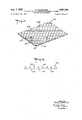
- FIG. 1 is a schematic drawing of a fabric in accordance with the present invention.
- FIG. 2 is a photograph of a fabric of the present invention, shown in the original photograph at actual size
- FIG. 3 is a photomicrograph of another type of fabric of the present invention at an original enlargement of 5 times.
- FIG. 4 is a photomicrograph of a cross-sectional view taken along a line similar to that shown as line 4-4 in FIG. 3 at an original enlargement of 10 times.
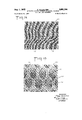
- FIG. 5 is a photomicrograph of another embodiment of the fabric of the present invention at an original enlargement of 5 times.
- FIG. 6 is a photomicrograph of the opposite surface of the fabric of FIG. 5 at an original enlargement of 5 times.
- FIG. 7 is a diagrammatic showing in elevation of one type of apparatus for carrying out the method for producing the fabrics of the present invention.
- FIG. 8 gives a perspective view of a portion of an apertured forming means that can be used with the apparatus of FIG. 7 to produce the fabrics of the present invention.
- FIG. 9 is an enlarged fragmentary diagrammatic plan view of a portion of a backing means that can be used in the apparatus of FIG. 7, an aperture of the apertured forming means being shown in dashed lines.
- FIG. 10 is a cross-sectional view taken along line 10-10 of F'IG. 9.
- FIG. 1l is a cross-sectional view taken along the line 11-11 of FIGS. 9 and l0.
- FIG. l2 is a perspective view of a portion of another type of backing means that can be used in the apparatus of FIG. 7 to produce fabrics similar to those shown in FIGS. 5 and 6.
- FIGS. 13 is a cross-sectional view taken along the line 13-13 of FIG. 1-2.
- FIG. 14 is a photograph of another embodiment of the fabric of the present invention.
- FIG. 15 is a photomicrograph of the fabric of FIG. 14 at an original enlargement of 5 times.
- FIG. 1 there is shown a nonwoven fabric 20 of the present invention.
- the fabric comprises a first regular or predetermined pattern of areas of low fiber density 21. These areas are disposed in discontinuous portions of the fabric.
- Each of the areas of low fiber density is at least partially defined by a plurality of yarn-like bundles 22 of liber segments. The segments in the bundles are closely associated with other segments in the bundle.
- These yarn-like bundles are interconnected at junctures 23 by groups of fibers common to a plurality of bundles.
- Each of these discontinuous portions of the fabric is bounded around its perimeter by a regular or predetermined pattern of yarn-like bundles 24 extending continuously throughout the fabric. These yarn-like bundles 24 are heavier in weight than the first mentioned yarn-like bundles 22.
- the discontinuous portions of the fabric are substantially rectangular in shape and are uniformly spaced in rows extending longitudinally and transversely of the fabric.
- the discontinuous portions 28 of the fabric are hexagonal in shape and are staggered in one direction and aligned in rows in the other direction.
- the discontinubus portions comprise a plurality of areas of low fiber density 29 some of which areas are fully deiined by yarn-like bundles 30 of fiber segments and other areas partially defined by such bundles of yarn-like fiber segments. All of the areas 2-9 are bounded around their perimeter by a continuous pattern of heavier yarn-like bundles 31 of ber segments. These heavier bundles are arranged in a hexagonal configuration.
- FIGS. 3 and 4 there is shown yet another fabric 33 of the present invention.
- the discontinuous portions 34 of the fabric have an oval shape and are aligned both transversely and longitudinally of the fabric. These discontinuous portions have areas of low ber density 35 which are at least partially defined by yarn-like bundles 36 of fiber segments. These discontinuous portions are bounded around their perimeter by a continuous pattern of heavier yarn-like bundles 37 of fiber segments. These heavier bundles extend transversely and longitudinally of the fabric. The difference in weight of these yarn-like bundles can be readily seen in the cross-sectional photomicrograph, FIG. 4.
- FIGS. and 6 of the drawings there is shown another embodiment of the novel fabric of the present invention; FIG. 5 showing one surface hereinafter referred to as the bottom surface and FIG. 6 showing the opposite surface of the same fabric and hereinafter referred to as the top surface.
- the fabric 40y as seen in FIG. 5 comprises a iirst regular or predetermined pattern of areas of low fiber density 41. The areas are located in discontinuous portions 42 of the fabric. The portions 42 are diamond shaped. Each area of low fiber density 41 is at least partially defined by yarn-like bundles 43 of liber segments. The diamond shaped portions are bound around their perimeter by a continuous pattern of yarn-like bundles 44 of iiber segments. The continuous pattern extends in crossing diagonals over the surface of the fabric.
- FIG. 7 shows one form of apparatus that may be used to produce the novel nonwoven fabric of the present invention. Full particulars of this apparatus, including methods of mounting, rotation, etc., are more fully described in my U.S. Pat. No. 2,862,251, issued Dec. 12, 1958, and are incorporated in the present application by reference and thus need not be described in complete detail here.
- the apparatus of FIG. 7 will be described in general terms insofar as its essential elements are the same as in the patent just mentioned, and the feature used to manufacture the novel nonwoven fabrics of the present invention, i.e., the backing means and its relationship to the apertured forming means, will be described in more detail.
- the apparatus of FIG. 7 includes a rotatable apertured drum 55 suitably mounted on hanged guide wheels 57 and 58.
- the drum has apertures 59 uniformly spaced over its entire surface, with the remaining portions of the drum constituting land areas 60.
- the guide wheels are mounted for rotation on shafts 65 and 66.
- a stationary manifold 67 to which a fluid is supplied through conduit 68 extends along the full width of the drum.
- a series of nozzles ⁇ 69 directing the fluid against the inside surface of the drum.
- Support member 70 is formed of a coarse woven screen, preferably metal.
- wires 90 ⁇ running vertically in FIG. 9 are straight, while wires 91 running horizontally in that gure weave alternately over and under wires 90.
- 8 lProtuberances 92 are presentthroughout foraminous portion 70 as the toprnost part of each knee of a given strand 91 of the screen that is formed as the strand weaves over and under the strands that lie perpendicular to it.
- a given strand 91 As a given strand 91 slants downward to pass under a strand 90 perpendicular to it, it crosses two other strands 91 disposed on either side of it, as those strands slant upward to pass over the same perpendicular strand that the given strand will pass under.
- IEach series of such crossing points 93 forms a trough, such as trough 94 in FIGS. 9 and 10, that lies between adjacent protuberances 92.
- the effective shape of troughs 94 as can be best seen in lFIG. 10 (which shows a cross section of element 70 of which a plan View is given in FIG. 9), is substantially an inverted triangle.
- a series of slightly deeper troughs is formed be'- tween adjacent protuberances 92 but extends at right angles to troughs 94.
- the bottom of each trough 95 is formed by portions of straight strands 90, with successive protuberances 92 on each side of the trough forming the tops ofthe trough.
- the effective shape of troughs 95 may be characterized as a shallow U-shape.
- FIG. 9 shows that a plurality of troughs 94 and a plurality of protuberances 92 alternate in one direction across the surface of foraminous backing means 70.
- FIG. 9 also shows that a plurality of troughs 95 and a plurality of protuberances 92 alternate in a direction perpendicular to troughs 94.
- a plurality of troughs and a plurality of protuberances alternate in both the longitudinal and transverse directions across the surface of foraminous backing means 70.
- the vertical distance between the tops of protuberances 92 and the bottoms of the immediately adjacent troughs should be at least about three times, generally no more than about 30 times, and preferably about ten times, the average diameter of the fibers in the layer of fibrous starting material.
- this distance is the vertical distance indicated in FIG. 10 by the pair of dashed lines that pass, respectively, through the tops of protuberances 92 and the crossing points 93 that define the troughs.
- the vertical distance from the bottom of each trough 95 to the tops of protuberances 92 is somewhat larger, being shown by FIGS. 10 and 11 to be equal to the diameter of a strand 91.
- support member 70 passes about drum 55 and separates from the drum at guide roll 71, which rotates on shaft 72.
- the support member passes downwardly around guide roll 73, rotating on shaft 74,
- Apertured forming drum 55 and backing belt 70 provide a rearranging zone between them through which a brous starting material may move, to be rearranged under the influence of applied uid forces into a nonwoven fabric having a plurality of patterns of yarn-like bundles of liber segments that alternate and extend throughout its area.
- Tension on the support member is controlled and adjusted by the tensioning and tracking guide roll.
- the guide rolls are positioned in slideable brackets which are adinstable to assist in the maintenance of the proper tension of the support member.
- the tension required will depend upon the weight of the fibrous web being treated and the amount of rearrangement and patterning desired in the nal product.
- Apertured drum 55 rotates in the direction of the arrow shown, and support member 70 moves in the same direction at the same peripheral linear speed and within the indicated guide channels, so that both longitudinal and lateral translatory motion of the backing means, the apertured forming means, and the fibrous layer with respect to each other are avoided.
- the fibrous material 81 to be treated is fed between the drum and support member at point A, passed through a fiber rearranging zone where fluid rearranging forces are applied to it, and is moved in its new, rearranged form as nonwoven fabric 82 between the support member and apertured drum at point 65B.
- a liquid such as water is directed against the inner surfaces of rotatable apertured drum 55 by nozzles 69 mounted inside the drum, the liquid passes through apertures 59 into the fibrous web to produce rearrangement of the fibers ⁇ of the web, and the water thence passes out through the backing means.
- vacuum assist box ⁇ 83 is located against the outside surface of the backing means 70.
- Vacuum box 83 has a slottedsurface located lclosely adjacent the outer surface of belt 70, and through which suction is caused to act upon the web. Suction thus applied assists in the rearrangement of the fibers as the web material passes through the rearranging zone. In addition, it serves to help de-water the web and prevent flooding during fiber rearrangement.
- Vacuum box 85 located below drum 55 also helps de-fwater the web after it is rearranged.
- aperture 59 spans a plurality of protuberances 92 on foraminous member 70 in both the longitudinal and transverse directions.
- each of the two protuberances 92 in registry with apertures 59-having a directional effect in one direction because of its proximity to other similar protuberances on backing means 70, and in the other direction for the same reason and in addition because of the cross-sectional shape of the protuberance-is effective in both the longitudinal and transverse directions.
- the first named protuberance 92 through cooperation with protuberances 92 lying just outside the two oclocfk position of aperture 59 in FIG. 9, is effective as a protuberance that defines 'one wall of trough 95 running horizontally across the middle of aperture 59.
- the cross sectional shape of each protuberance 92 exerts a directional effect on the fibers of the -librous starting material by its sharper definition of the side walls of each trough extending horizontally across FIG. 9, i.e., on the side walls of each trough 95.
- the directions the streams of rearranging fiuid projected through apertures 59 of apertured forming means 55 take as they move into and through the fibrous web determine the type of forces applied to the fibers and, in turn, the extent of rearrangement of the fibers. Since the directions the stream of rearranging fluid take after they pass through apertures 59 are determined lby the pattern of the solid wires that make up lbacking means 70, and in particular, the pattern of protuberances and troughs distributed across the surface of means 70, it follows that the pattern of these areas helps determine the patterns of holes or other areas of low fiber density in the resultant fabric.
- portions of the streams of rearranging fluid that have passed through forming apertures 59 and the fibrous web can pass directly through openings 96 in foraminous backing means 70.
- Other portions of the streams or rearranging :duid that have passed through apertures 59 strike the wires of woven screen '70, at protuberances 92 or at other portions of the wire, and are defiected sidewise before they pass out of the rearranging zone through openings 96.
- FIGS. 10 and 11 give a schematic showing of the path followed by a stream of rearranging liuid 97 that is directed through aperture 59 into the layer of fibrous starting material in a direction perpendicular to that layer, to strike protuberance 92 in the ten oclock position of aperture 59 in FIG. 9.
- the stream of fiuid is deflected downwardly and outwardly away from its perpendicular direction of entry into the fiber rearranging zone, and then moves out of the rearranging zone through openings between wires and 91.
- backing means 70 and apertured forming means 55 are employed in the method or apparatus of this invention as shown in FIG. 9, some of the fiber segments in registry with apertures 59 of apertured forming means 55 are moved by streams of rearranging fiuid into surrounding areas of the fibrous layer and are there positioned in a first pattern of yarn-like bundles of closely associated vand substantially parallel fiber segments that is complementary to apertures l59.
- a second pattern of yarn-like bundles of fiber segments is created within the first pattern, being formed of yarn-like bundles that are positioned in troughs 94 and 95 on backing means 70 when other fiber segments that are in registry with apertures 59 of forming means 55 are moved by the fluid rearranging forces into the troughs.
- the fibrous web When the layer of fibrous starting material is first positioned in the liber rearranging zone between apertured forming means ⁇ 55 and foraminous backing means 70, before a rearranging fiuid has been directed through apertures '59 of forming means 55, the fibrous web of course lies upon the tops of protuberances 92. After fiber rearrangement has proceeded under the impact of rearranging fluid introduced through apertures 59, the fibers are moved down the sloping sides of protuberances 92 into troughs 94 and 95. At this juncture, the layer of rearranged fibers that comprises the nonwoven fabric ordinarily lies l9argely, if not altogether, below the tops of protuberances Referring to FIGS.
- the backing means comprises a woven wire screen 101 having a relatively smooth surface as compared to the screen described in conjunction with FIGS. 9 through 11.
- a net-like material 102 having diamond shaped openings 103 formed by solid strands 104 running diagonally to each other.
- the solid strands 104 extend above the surface of the wire screen 101.
- the apertures 59 in the forming member ⁇ 55 are smaller than the openings 10'3 in the net-like material but larger than the openings 105 in the wire screen 101.
- the width of the strands 104 is substantially the same size as the width of an aperture 59 in the forming means 55.
- the fiber segments tend to be washed olf the top of the solid strands 104 and accumulate in the opening 103.
- the fibersegments in the opening 103 are rearranged into areas of low fiber density which are defined by yarn-like bundles of liber segments.
- the rearranging forces produce a pattern of yarnlike bundles which extend from the center of one opening such as 103a to the center of the diagonally adjacent opening such as 103b to form a fabric similar to that depicted in FIGS. 5 and 6.
- the rearranged web or fabric of this invention may be treated with an adhesive, dye, or other impregnating, printing, or coating material in a conventional manner.
- any suitable adhesive bonding materials or binders may be included in an aqueous or non-aqueous medium employed as the rearranging fluid.
- an adhesive binder may, if desired, be printed on the rearranged web to provide the necessary fabric strength.
- Thermoplastic binders may, if desired, be applied to the rearranged web prior, during or after rearrangement in powder or other form and then fused to bond the fibers.
- the optimum binder content for a given fabric according to this invention depends upon a number of factors, including the nature of the binder material, the size and shape of the binder members and their arrangement in the fabric, the nature and length of the bers, total fiber weight, and the like. In some instances, because of the strength of the fibers used or the tightness of their interentanglement in the rearranged web or fabric, no binder at all need be employed to provide a usable fabric.
- EXAMPLE l In apparatus as illustrated in FIG. 7, a web 81 of loosely assembled fibers, such as may be obtained by cardng, is fed between apertured forming means 55 and backing means 70.
- the web weight is about 450 grains per square yard, and its fiber orientation ratio approximately 7 to 1 in the direction of travel.
- the web contains viscose rayon fibers approximately 1%6" long of 111/2 denier.
- Apertured forming means 55 has about 30 round apertures per square inch, each having a diameter of about Ms. These apertures 59 are arranged in a rectangular pattern over forming means 70, with each aperture spaced approximately 0.075 from adjacent apertures in the longitudinal direction and approximately 0.040" from adjacent apertures in the transverse direction.
- Backing means 70 comprises a coarse woven wire screen similar to that shown in FIGS. 9 through 1l.
- the screen is approximately 14 x 18 mesh or substantially 252 openings per square inch.
- the vertical distance between the tops of protuberances 92 and troughs 94 such as shown in FIGS. 9 and 10 is approximately 0.005, or in other words, a little more than three times the 0.0015 average diameter of the 112 denier fibers making up the starting material.
- the same vertical distance for troughs such as those shown in FIG. 1l is slightly larger.
- the horizontal distance between the tops of protuberances 92 is about 0.056 in one direction and about 0.071 in the other. These distances are equal, respectively, to about 37 times and about 47 times the 0.0015" average diameter of the fibers of the fibrous starting material.
- Each aperture 59 spans a plurality of protuberances 92 on backing screen 70, measured in both the longitudinal and transverse direction.
- Apertured forming means 55 and permeable backing means 70 are spaced from each other during use of the apparatus of FIG. 7 to provide a fiber rearranging zone therebetween.
- Water is projected from nozzle 69 through apertures 59 in apertured forming means 55, and sent through fibrous web 81 and backing means 70.
- Nonwoven fabric 33 of FIG. 3 contains larger areas of low fiber density 34, each of which has a shape generally similar to apertures 59 and is defined by heavy yarn-like bundles 37 of closely associated and substantially parallel fiber segments.
- Yarn-like bundles 37 are arranged in accordance with the configuration of land areas 60 of apertured forming means 55, or in other words, in a rst pattern complementary to forming apertures 59 of forming means 55.
- Each yarn-like bundle 37 is connected with other such bundles to form a continuous line or lines that may be traced throughout the nonwoven fabric 33.
- nonwoven fabric 33 contains smaller areas of low fiber density 35, arranged in accordance with the pattern of arrangement of protuberances 92 on permeable backing means 70. As indicated, areas of low ber density 35 are smaller than areas 34, and lie within these areas.
- Each of the areas 35 is defined by yarn-like bundles 36 of closely associated and substantially parallel fiber segments, which have been positioned by the fluid rearranging forces of this invention in troughs 94 and 95 of back-i Yarn-like bundles 36 are connected with each other. and with yarn-like bundles 37 at junctures by groups of.
- FIG. 4 gives a cross sectional view of the fabric of- EXAMPLE 2
- FIG. 2 gives a photomicrograph of another nonwoven fabric made in accordance with the present invention.
- the starting material is a web similar to the starting material of Example 1, except that it has a web weight of approximately 35.0 grains per square yard.
- Apertured forming means 55 used in this example is a cylinder formed of metal strips arranged in a honeycomb pattern of contiguous hexagonal openings 59. The distance between parallel opposite sides of each hexagonal shaped forming aperture 59 is about 7/16". The metal strips comprising the honeycomb structure are approximately 0.040 in thickness and about 3A" in depth. A perspective drawing of a portion of such a metallic honeycomb structure is provided in FIG. 8.
- Backing means 70 comprises a coarse woven wire screen 70 having alternating protuberances 92 and troughs 94 and 95 similar to that used in Example l.
- One pair of parallel, opposite sides of each hexagonal shaped forming aperture lie generally above the fiber accumulating troughs on the backing means.
- Example 2 Using the same general mode 'of operation as in Example 1, an excellent nonwoven fabric of attractive appearance such as is shown in the photomicrograph of FIG. 2 is obtained.
- Nonwoven fabric 27 of FIG. 2 contains areas of low fiber density 28, each of which has the general hexagonal shape of forming apertures 59, and is defined by yarnlike bundles 31 of closely associated and substantially parallel fiber'segments. These bundles are accumulated, by application of the fluid rearranging forces, under the land areas of the honeycomb apertured forming means 55, and are arranged in a first pattern complementary to the pattern of forming apertures 59, i.e., in interconnected hexagonal patterns. Each yarn-like bundle 31 is connected with other such bundles to form a continuous line or lines that may be traced throughout nonwoven fabric 27.
- nonwoven fabric 27 contains areas of low fiber density 29 that are arranged in accordance with the pattern of arrangement of protuberances on backing means 70.
- Each of these areas of low fiber density 29 is defined by yarn-like bundles of fiber segments 30, which are bundled and positioned by the fluid rearranging forces in a second pattern corresponding to the pattern of troughs 94 and 95 of backing means 70.
- areas of low fiber density 29 defined by the second pattern of yarnlike bundles 30 are smaller than and lie within areas of low fiber density 28 defined by the first pattern of yarnlike bundles 31.
- Yarn-like bundles 30 are connected with each other and with yarn-like bundles 31 at junctures by groups of fibers common to a plurality of bundles, the fibers at such junctures being oriented in a plurality of diverse directions.
- EXAMPLE 3 In this example, a web similar to that employed in Example l is positioned between apertured forming means and backing means, while water is projected through the apertures of the forming means to pass through the fibrous web and then the backing means. Vacuum is applied to the backing means of the side of that means that is op- 14 posite the fiber rearranging zone, to assist in liber rearrangement.
- the apertured forming means employed is a nylon knitted mesh known as a raschel knit fabric, with oval openings approximately l/16" by ls".
- the oval openings are distributed over the area of the apertured forming means in a diamond pattern, with a space of approximately y between them measured in the diagonal direction. There are 24 openings per square inch.
- the backing means used in this example comprises a woven nylon screen of approximately 28 x 34 mesh, or substantially 952 openings per square inch.
- the vertical distance between the top of the protuberances formed by the knees of the woven screen and the bottom of the troughs lying between the protuberances is about 0.00
- tops of the protuberances on the backing means are spaced approximately 0.029 in one direction and approximately 0.036 in the other. This is equivalent, respectively, to about 20 times and about 24 times the average diameter of the bers of the fibrous starting material.
- vacuum assist results in a plurality of discontinuous, oval shaped fiber rearranging zones spaced from each other, with a continuous interconnecting zone between those discontinuous zones in which the apertured forming means and backing means, under the influence of the applied vacuum assist, clamp the fibrous starting material so tightly that the fluid rearranging forces are not capable of effecting fiber rearrangement in that zone.
- an attractive nonwoven fabric such as is shown in the photograph, FIG. 14 and the photomicrograph, FIG. 15, is obtained.
- a rst pattern of heavier yarn-like bundles 111 of fiber segments is positioned, with some of the yarn-like bundles 111 extending in the longitudinal direction and some in the transverse direction, around the entire perimeter of each of the oval shaped areas 112 of the resulting fabric that corresponds to an aperture of the apertured forming means.
- a second pattern of yarn-like bundles 113 of fiber segments having a lighter weight are positioned in both the longitudinal and transverse directions, in accordance with the pattern of the troughs on the backing means.
- the second pattern of yarn-like bundles 113 define a plurality of holes 114 or areas of low fiber density.
- Yarn-like bundles 111 are interconnected with yarn-like bundles 113, and the latter are connected with each other at junctures by fibers common to a plurality of bundles, the fibers at said junctures being oriented in a plurality of diverse directions.
- EXAMPLE 4 In apparatus as illustrated in FIG. 7, a web 81 of loosely assembled fibers, such as may be obtained by carding, is fed between apertured forming means 55 and backing means 70.
- the web weight is about 400 grains per square yard, and its fiber orientation ratio approximately 7 to 1 in the direction of travel.
- the web contains viscose rayon fibers approximately 1%6 long, of 11/2 denier.
- the apertured forming means 55 used in this example has about substantially round holes per square inch, each approximately .045" in diameter or about 30 times the average diameter of the fibers of the fibrous starting material.
- the holes are arranged in a diamond pattern over the forming means.
- Each aperture 59 is spaced approximately .040" from the diagonally adjacent aperture on the drum.
- the backing means used in this example is similar to that depicted in FIGS. 12 and 13.
- the discontinuous foraminous portions of backing means 100 are comprised of a woven nylon screen of approximately 28 x 34 mesh or substantially 952 openings per square inch.
- Each fo- 15 raminous portion is oval or diamond in shape, measuring approximately JAG in one direction and approximately Ms in the other, and is spaced about 1/6" from the immediately adjacent foraminous portions.
- Foraminous portions 103 are distributed in a diamond pattern, 24 to the square inch, over backing means 100.
- Continuous imperforate portions 104 of backing means 100 comprise a nylon knitted mesh knowns as raschel knit fabric, of the form shown in plan view in FIG. 12 and in cross section in FIG. 13.
- the width of each imperforate portion 104 at its narrowest part is approximately 1/16 or about 0.063", which is about one-and-a-half times the diameter of each aperture 59 of apertured forming means 55.
- the grid of imperforate portions defines foraminous portions 103.
- the height of each irnperforate portion 104 is approximately 1/32" at its rounded top portion.
- Nonwoven fabric 40 of FIGS. 5 and 6 contains areas of low fiber density 41. Each area 41 is at least partially defined by yarn-like bundles 43 of fiber segments. These areas of low fiber density 41 and yarn-like bundles 43 are located in discontinuous portions 42 of the fabric and each portion 42 is bound by a pattern of yarn-like bundles 44 of closely associated and substantially parallel fiber segments. i
- Each yarn-like bundle 44 is connected with other such bundles to form a continuous line or lines that may be traced throughout nonwoven fabric 40 in an interconnected pattern to form diamond shaped discontinuous portions 42.
- Yarn-like bundles 44 are connected with each other and with yarn-like bundles 43 at junctures by groups of fibers common to a plurality of bundles, the fibers at such juuctures being oriented in a plurality of diverse directions.
- a nonwoven fabric with a plurality of patterns of groups of ber segments that alternate and extend throughout said fabric which comprises: a first regular pattern of yarn-like bundles of fiber segments that define areas of low fiber density, in first discontinuous portions of the fabric, the fiber segments in each of bundles being closely associated with other fiber segments in the bundle and lying generally parallel to the longitudinal axis of the bundle, each of said yarn-like bundles of fiber segments being interconnected with other bundles at junctures by groups of fibers common to a plurality of bundles, the fibers at said junctures being oriented in a plurality of diverse directions, each of said first discontinuous portions of the fabric being bounded around its 16 perimeter by a second plurality of yarn-like bundles of fiber segments, the fiber segments in each of said bundles being closely associated with other fiber segments in the bundle and lying generally parallel to the longitudinal axis of the bundle, said second mentioned yarn-like bundles being located in continuous portions of the fabric that lie between and interconnect said discontinuous portions of the fabric and form a second regular pattern.
- each of said second mentioned yarn-like bundles is connected with other such bundles to form a continuous line extending throughout said fabric.
Abstract
A nonwoven fabric having a plurality of patterns of groups of fiber segments that alternate and extend throughout the fabric. One of the patterns comprises a plurality of yarn-like bundles of fiber segments that define apertures or holes or other areas of low fiber density located in discontinuo portions of the fabric. The discontinuous portions of the fabric are bounded around their perimeters by a second continuous pattern of yarn-like bundles of fiber segments.
Description
ug l, 1972 F. KALwAlTEs NONWOVEN FABRICS COMPRISING BAMBOO, DIAMOND AND THE LIKE PATTERNS 6 Sheets-Sheet 1 Filed March 24 i970 h Til-:1.5
l INVENTOR 56m/Af a n4/72's ATTORNEY Aug- 1, 1972 F. KALwAn'Es 3.581.184
NONWOVEN FABRICS COMPRISING BAMBOO, DIAMOND AND THE LIKE PATTERNS Filed March 24, 1970 6 Sheets-Sheet 2 lNvENroR KALWAITES ATTORNEY Aug. l., 1872 F. KALWAITES NONWOVEN FABRICS COMPRISING BAMBOO, ;DIAMOND AND THE LIKE PATTERNS 6 Sheets-Sheet 5 Filed March 24, 1970 INVENTOR FRANK KALwAn'Es ATTORNEY Aug. l, 1972 F. KALwAlTl-:s 3,681,184
NONWOVEN FABRICS COMPRISING BAMBOO, .DIAMOND Y AND THE LIKE PATTERNS Filed March 24, 1970 6 Sheets-Sheet 4 Y INVEN-ron FRANK KALWAITES .BYQVZQW ATTORNEY Aug. l, 1972 F. KALwArrEs 3,681,184
NONWOVEN FABRICS COMPRISING BAMBOO, IDIAMOND AND THE LIKE PATTERNS Filed March 24, 1970 6 Sheets-Sheet 5 Vl 1E INVENTOR Fea/ Aix/ Ww rss ATTORNEY ug l, 1972 F. KALwArrEs NONWOVEN FABRICS COMPRISING BAMBOO, :DIAMOND AND THE LIKE PATTERNS 6 SheetsSheet 6 Filed March 24, 970
INVENTOR F'R K KALwAn'es im M.
ATTORNEY AUnited States Patent Oji 3,681,184 Patented Aug. l, 1972 U.S. Cl. 161-109 9 Claims ABSTRACT OF THE DISCLOSURE A nonwoven fabric having a plurality of patterns of groups of ber segments that alternate and extend throughout the fabric. One of the patterns comprises a plurality of yarn-like bundles of ber segments that define apertures or holes or other areas of low ber density located in discontinuous portions of the fabric. The discontinuous portions of the fabric are 'bounded around their perimeters by a second continuous pattern of yarnlike bundles of ber segments.
The present invention relates to nonwoven fabrics, and more particularly to patterned nonwovenv fabrics made from a layer of brous material such as a brous web wherein the individual ber elements are capable of movement under the influence of applied fluid forces. The rst pattern in the fabric is a pattern of yarn-like bundles of closely associated and substantially parallel ber segments that dene apertures (holes) or other areas of low ber density in discontinuous portions of the fabric. The second pattern is a pattern of yarn-like bundles of ber segments in continuous portions of the fabric that lie between and interconnect the discontinuous portions of the fabric.
BACKGROUND OF INVENIlION For a number of years now, there have been known Various types of foraminous or apertured nonwoven fabrics made by processes involving the rearrangement of bers in a starting web or fabric of nonwoven bers. Some of these fabrics and methods of manufacture are illustrated, shown and described in U.S. Pats. 2,862,251; 3,081,500; 3,081,512; 3,081,514 and 3,081,515. The fabrics disclosed and claimed in the patents just listed contain apertures or holes or other areas of low ber density outlined by interconnected bundles of fibrous elements wherein the ber segments within the bundle are closely associated and substantially parallel and have a yarn-like conguration. The term areas of low ber density is used in this specication and claims to include both areas in which relatively few fibers in comparison to the rest of the fabric are found and apertures (holes) that are substantially or entirely free of bers. Such fabrics will be hereinafter referred to as bundled rearranged nonwoven fabrics.
Bundled rearranged nonwoven fabrics have been made commercially for many years. In most instances, these fabrics have had an overall pattern of holes or other low ber density areas throughout the fabric.
LA method for producing bundled rearranged nonwoven fabrics is to support a loose fibrous web or layer on a permeable backing member and apply sets of opposing fluid forces to the layer while thus supported. The fluid by which such forces are applied passes through the brous layer over the backing member and then through the backing member to pack various groups of fibers elements and to place these elements into closer proximity and substantial parallelism to form interconnected bundles .of ber segmentsAIn accomplishing this result, the fluid forces usually are applied over the entire surface of the loose fibrous web or layer and uniformly over and through the permeable backing or support member to produce ber :bundles uniformly over the entire fabric. In some instances, patterns can be made in the fabric by not applying fluid forces to predetermined areas of the fibrous layer thereby preventing rearrangement in these areas.
SUMMARY OF INVENTION I have discovered a novel nonwoven fabric which comprises a layer of intermingled fibers with the bers arranged to dene a plurality of patterns. The rst pattern is located in discontinuous areas of the fabric. These discontinuous areas comprise a plurality of yarn-like bundles of fiber segments that dene apertures or holes or other areas of low ber density. The ber segments in each of the bundles are closely associated with other ber segments in the bundle and lie generally parallel to the longitudinal axis of the ibundle. The yarn-like bundles of ber segments are interconnected with other bundles at junctures by groups of fibers common to a plurality of bundles. The bers at said junctures are oriented in a plurality of diverse directions. The discontinuous portions of the fabric are bound around their perimeter by a second pattern of yarn-like bundles. This second pattern of yarnlike bundles is continuous throughout the fabric. The yarn-like bundles of the second pattern may be of a different weight than the yarn-like bundles in the first discontinuous portions of the fabric.
In certain embodiments of the present invention, the yarn-like bundles in the predetermihed continuous portions of the fabric are heavier than the yarn-like bundles in the discontinuous portions of the fabric. Also, in certain other embodiments, the yarn-like bundles in the continuous portions of the fabric will extend longitudinally and transverse of the fabric while in other embodiments, they may extend in various other continuous shapes throughout the fabric. The discontinuous portions of the fabric may have various shapes; that is, square, round, hexagonal, etc.
Surprisingly, even though my new fabric has a plurality of patterns which extend throughout the fabric, the patterns have substantial regularity and aid in providing a fabric having considerably aesthetic appeal. Furthermore, not only does my new fabric have substantial uniformity in its areas of low ber density or holes, but unexpectedly, my new fabric has uniformity in the patterns of bundles of ber segments, including both the pattern of bundles in the discontinuous portions of the fabric and the pattern of bundles which bound the perimeters of the discontinuous portions.
METHOD OF MAKING THE FABRIC 0F THIS IN- VENTION AND FURTHER DESCRIPTION OF IN- VENTION In the method for making the fabric of this invention,
the starting material is a layer of brous material whose individual bers are in mechanical engagement with one another but are capable of movement under applied fluid forces. The layer of brous starting material is supported in a ber rearranging zone in which ber movement in directions parallel to the plane of said brous material is permitted in response to applied fluid forces. Streams of rearranging fluid, preferably water, are then projected into the brous layer, in a direction perpendicular to the layer, at entry zones spaced from each other adjacent the entry side of the rearranging zone.
Each stream of rearranging fluid entering an entry zone is passed through the initial part of the rearranging zone, as the brous starting material lies in that zone, toward two or more dispersal points lying directly opposite the entry zone and adjacent the exit side of the rearranging zone. In the next step of the method, rearranging fluid is deflected at each such dispersal point diagonally and downwardly, into the area immediately surrounding the dispersal point, away from the perpendicular direction at which the fiuid was first projected into the fibrous starting layer.
This defiection of the rearranging fluid moves fiber segments lying opposite an entry zone into the area surrounding a dispersal point opposite that entry zone, and positions some of those fiber segments in yarn-like bundles ofclosely associated and substantially parallel fiber segments in areas of the fibrous starting material surrounding the entry zone. Other fiber segments moved by the rearranging fluid away from a dispersal point are positioned in similar yarn-like bundles in fiber accumulating zones that lie between adjacent dispersal points and are in registry with an entry zone. The deflected and undefiected portions of the rearranging fluid are then intermingled and passed out of the fiber rearranging zone through spaced exits at the exit side of the rearranging zone.
In one form of the method and apparatus Ifor producing the novel fabrics of this invention, the fibrous starting layer is supported on a foraminous backing means having a plurality of protuberances and troughs alternating across its surface in both the longitudinal and transverse directions, apertured forming means is positioned above the fibrous layer, and streams of rearranging fluid, preferably water, are projected through the apertures of the apertured forming means and against the fibrous starting material. The vertical distance between the tops of the protuberances on the backing means and the bottoms of the immediately adjacent troughs is equal to at least about three times the average diameter of the fibers in the layer of fibrous starting material. Each of the apertures in the apertured forming means is wide enough to span two or more of the protuberances on the backing means.
The resulting novel nonwoven fabric displays a plurality of patterns of yarn-like bundles of fiber segments that alternate and extend throughout the fabric. The first of these is a pattern of yarn-like bundles of fiber segments that have been positioned in the troughs on the surface of the foraminous backing means. These yarn-like bundles at least partially define holes or other areas of low fiber density in discontinuous portions of the fabric. The second pattern is a pattern of yarn-like bundles arranged in accordance with the configuration of the land areas of the apertured forming means. These yarn-like bundles surround the discontinuous portions of the fabric to form a continuous pattern of yarn-like bundles in the fabric.
The basic method and apparatus for producing the fabrics of this invention are shown and described fully in my U.S. Pat. No. 2,862,251, issued Dec. 2, 1958. Pull particulars of the basic invention as disclosed in that patent are incorporated in this application by reference, although some of those particulars are repeated here. In addition, the specific features peculiar to the method and apparatus for making the novel plural pattern nonwoven fabrics of the present invention are described in detail in this application.
Starting material-The starting material used for producing the novel nonwoven fabrics of this invention may be any of the standard fibrous webs such as oriented card webs, isowebs, air-laid webs, or webs formed by liquid deposition. The webs may be Iformed in a single layer, or by laminating a plurality of the webs together. The fibers in the web may be arranged in a random manner or may be more or less oriented as in a card web. The individual fibers may be relatively straight or slightly bent. The fibers intersect at various angles to one another such that, generally speaking, the adjacent fibers come into contact only at the points where they cross. 'Ihe fibers are capable of movement under forces applied by uids such as water, air, etc.
To produce a fabric having the characteristic hand and drape of a textile fabric, the layer of starting material used may comprise natural fibers such as cotton, flax, etc.; mineral fibers such as glass; artificial fibers such as viscose rayon, cellulose acetate, etc.; or synthetic fibers such as the polyamides, the polyesters, the acrylics, the polyolefins, etc., alone or in combination with one another. The fibers used are those commonly considered textile fibers; that is, generally fibers having a length from about 1A inch to about 2 to 21/2 inches. Satisfactory products may be produced in accordance with this invention from starting webs weighing between grains per square yard to 2,000 grains per square yard or higher.
Backing means ln producing the novel nonwoven fabrics of this invention, the fibrous starting layer is supported on a backing means that is foraminous and is provided with a plurality of protuberances and troughs alternating across its surface in both the longitudinal and transverse directions.
Thetops of the protuberances rise above the bottoms of the immediately adjacent troughs by a distance equal to at least about three times but generally no more than about 30 times, the average diameter of the fibers in the layer of fibrous starting material. Preferably, the distance should be equal to about ten times the average diameter of those fibers. The protuberances should not rise so far above their immediately adjacent troughs as to disrupt formation of the pattern of yarn-like bundles of fiber segments corresponding to the land areas of the apertured forming means.
The fibrous starting material used is comprised of closely intertwined and interentangled fibers arranged (depending upon the degree of fiber orientation in the layer) in a more or less helter-skelter fashion. Some of the fibers of the starting lmaterial will by random chance lie generally parallel to the troughs of the backing means over which they lie, but the great majority of the fibers will lie at an angle to the longitudinal axis of the trough, and a substantial number of these will lie at angles of 45 or more to that axis.
Now, as already indicated, the fiuid rearranging forces of this invention tend to move some fiber segments that are in registry with an aperture of the apertured forming means sidewise until they are no longer in registry with the aperture, to position those segments in yarn-like bundles lying under the land areas of the apertured forming means. At the same time, streams of rearranging fluid move other fiber segments that are in registry with the aperture into closer association and substantial parallelism with each other in yarn-like bundles in the troughs of the backing means. The latter type of fiber movement is more likely to occur with ber segments in the starting material that lie only a relatively few degrees away from aposition parallel to the longitudinal axis of a trough.
In other words, this type of movement is more difficult the greater the angle between a given fiber segment and lthe axis of the trough, and when fiber segments lie at too great an angle to the longitudinal axis of a trough, they are pushed altogether out of registry with the forming aperture under which they lie so that they are pushed entirely into the surrounding land areas of the apertured forming means. For the greater the angle `between the fiber segment and the trough axis, the shorter is the portion of the fiber that bridges the trough, and the more difficult it is for the rearranging fiuid forces to get a purchase on the fiber segment to turn it around into a position parallel with the trough axis.
Likewise, the narrower the troughs are on the backing means, the more difficult it is for the rearranging fluid forces to get a purchase on the short portion of the fiber segment that bridges the trough, to swing that segment around into a position parallel to the axis of the trough to be consolidated there to form a yarn-like bundle with other similarly positioned fiber segments. For this reason, the distance between immediately adjacent protuberances on the backing means, which determines the width of a trough from the top of one side to the other,
is ordinarily greater than about 30 times the average diameter of the fibers of the fibrous starting material.
This spacing may be smaller if a vacuum is employed to help rearrange the fibers of the starting material, since the force of the vacuum is then added to the force of the other rearranging fluid employed. With the use of a vacuum assist, the spacing of immediately adjacent protu- Iberances on the backing means is at least about 15 times the average diameter of the bers of the fibrous starting material.
The minimum spacing of protuberances just mentioned, which affects the width of the troughs lying between immediately adjacent protuberances, also assists in providing good visual resolution between various yarn-likebundles of iibersegments in the fabric resulting from the practice of this invention. For if the protuberances are too closely spaced and the troughs between them are too narrow, yarn-like bundles of fiber segments may be accumulated in the troughs but will not be discernible one from the other, because each one merges into the next adjacent similar bundle of iiber segments.
If the web weight of the brous starting material is high, the distance between immediately adjacent protuberances on the backingmeans should be increased, or other- Wise the yarn-like bundles of ber segments will be masked out by the same merging phenomenon just mentioned. Again, satisfactory visual resolution of immediately adjacent yarn-like bundles of liber segments can be had with somewhat closer spacing of protuberances if the rearrangement of fibers is assisted by the application of vacuum.
Apertured forming means-The uid entry zones into the fiber rearranging zone as described previously are defined yby an apertured forming means that is solid throughout its areas except for the forming apertures disposed longitudinally and transversely across the member. The forming apertures must be substantially larger in area than the openings in the foraminous backing means. The forming apertures may have any desired shape, i.e., round, square, diamond, oblong, free form, etc.
The land areas of the apertured forming means that lie between and interconnect the forming apertures may be either narrow or broad in comparison to the forming apertures as desired. Generally speaking, the narrower the width of the land areas, the more tightly compacted will be the yarn-like bundles of closely associated and substantially parallel fiber segments that are formed under those land areas in the nonwoven fabric of this invention.
For the clearest visual resolution between bundles of fiber segments in the nonwoven fabrics of this invention, each aperture of the apertured forming means should span a plurality of the protuberances on the backing means. For still better results, each aperture in the apertured forming means should span a plurality of protuberances on the backing means measured in both the longitudinal and transverse directions, with the land area defining the forming aperture lying generally above a trough in the foraminous backing means. 1
During the use of the method or apparatus, the apertured forming means and the foraminous backing means are spaced from each other to provide a fiber rearranging zone in which iiber movement in directions parallel to the backing means is permitted in response to applied fiuid forces.
Rearranging fluid-The rearranging fluid for use with this invention is preferably water or a similar liquid. It may also be other fiuids such as a gas, as described in my Pat. No. 2,862,251.
BRIlEF DESCRIPTION OF THE DRAWINGS The invention will be more fully described in conjunction with the accompanying drawings wherein:
FIG. 1 is a schematic drawing of a fabric in accordance with the present invention.
FIG. 2 is a photograph of a fabric of the present invention, shown in the original photograph at actual size,
FIG. 3 is a photomicrograph of another type of fabric of the present invention at an original enlargement of 5 times. f
FIG. 4 is a photomicrograph of a cross-sectional view taken along a line similar to that shown as line 4-4 in FIG. 3 at an original enlargement of 10 times.
FIG. 5 is a photomicrograph of another embodiment of the fabric of the present invention at an original enlargement of 5 times.
FIG. 6 is a photomicrograph of the opposite surface of the fabric of FIG. 5 at an original enlargement of 5 times.
FIG. 7 is a diagrammatic showing in elevation of one type of apparatus for carrying out the method for producing the fabrics of the present invention.
FIG. 8 gives a perspective view of a portion of an apertured forming means that can be used with the apparatus of FIG. 7 to produce the fabrics of the present invention.
FIG. 9 is an enlarged fragmentary diagrammatic plan view of a portion of a backing means that can be used in the apparatus of FIG. 7, an aperture of the apertured forming means being shown in dashed lines.
FIG. 10 is a cross-sectional view taken along line 10-10 of F'IG. 9.
FIG. 1l is a cross-sectional view taken along the line 11-11 of FIGS. 9 and l0.
FIG. l2 is a perspective view of a portion of another type of backing means that can be used in the apparatus of FIG. 7 to produce fabrics similar to those shown in FIGS. 5 and 6.
FIGS. 13 is a cross-sectional view taken along the line 13-13 of FIG. 1-2.
FIG. 14 is a photograph of another embodiment of the fabric of the present invention.
FIG. 15 is a photomicrograph of the fabric of FIG. 14 at an original enlargement of 5 times.
DETAILED DESCRIPTION OF SPECIFIC EMBODIMENTS OF 'PI-IISl INVENTION Referring to the figures, FIG. 1, there is shown a nonwoven fabric 20 of the present invention. The fabric comprises a first regular or predetermined pattern of areas of low fiber density 21. These areas are disposed in discontinuous portions of the fabric. Each of the areas of low fiber density is at least partially defined by a plurality of yarn-like bundles 22 of liber segments. The segments in the bundles are closely associated with other segments in the bundle. These yarn-like bundles are interconnected at junctures 23 by groups of fibers common to a plurality of bundles. Each of these discontinuous portions of the fabric is bounded around its perimeter by a regular or predetermined pattern of yarn-like bundles 24 extending continuously throughout the fabric. These yarn-like bundles 24 are heavier in weight than the first mentioned yarn-like bundles 22. The discontinuous portions of the fabric are substantially rectangular in shape and are uniformly spaced in rows extending longitudinally and transversely of the fabric.
In the photograph in EFIG. 2 there is shown another fabric 27 of the present invention. In this fabric, the discontinuous portions 28 of the fabric are hexagonal in shape and are staggered in one direction and aligned in rows in the other direction. The discontinubus portions comprise a plurality of areas of low fiber density 29 some of which areas are fully deiined by yarn-like bundles 30 of fiber segments and other areas partially defined by such bundles of yarn-like fiber segments. All of the areas 2-9 are bounded around their perimeter by a continuous pattern of heavier yarn-like bundles 31 of ber segments. These heavier bundles are arranged in a hexagonal configuration.
Referring to the photomicrograph in FIGS. 3 and 4, there is shown yet another fabric 33 of the present invention. In this fabric the discontinuous portions 34 of the fabric have an oval shape and are aligned both transversely and longitudinally of the fabric. These discontinuous portions have areas of low ber density 35 which are at least partially defined by yarn-like bundles 36 of fiber segments. These discontinuous portions are bounded around their perimeter by a continuous pattern of heavier yarn-like bundles 37 of fiber segments. These heavier bundles extend transversely and longitudinally of the fabric. The difference in weight of these yarn-like bundles can be readily seen in the cross-sectional photomicrograph, FIG. 4.
Referring to FIGS. and 6 of the drawings, there is shown another embodiment of the novel fabric of the present invention; FIG. 5 showing one surface hereinafter referred to as the bottom surface and FIG. 6 showing the opposite surface of the same fabric and hereinafter referred to as the top surface. The fabric 40y as seen in FIG. 5 comprises a iirst regular or predetermined pattern of areas of low fiber density 41. The areas are located in discontinuous portions 42 of the fabric. The portions 42 are diamond shaped. Each area of low fiber density 41 is at least partially defined by yarn-like bundles 43 of liber segments. The diamond shaped portions are bound around their perimeter by a continuous pattern of yarn-like bundles 44 of iiber segments. The continuous pattern extends in crossing diagonals over the surface of the fabric. However, because of the manner in which this fabric is made and the weight of the starting fibrous material, the opposite surface or top surface of the fabric as seen in lFIG. 6', also shows a somewhat heavier deposition of fibers at each point 45 where the diagonally disposed yarn-like bundles 44 cross each other. This heavier deposition of fiber gives the fabric a three-dimensional appearance and somewhat obscures the basic pattern of the fabric when the fabric is viewed from the top surface.
Description of machine and method for making fabrics of my invention FIG. 7 shows one form of apparatus that may be used to produce the novel nonwoven fabric of the present invention. Full particulars of this apparatus, including methods of mounting, rotation, etc., are more fully described in my U.S. Pat. No. 2,862,251, issued Dec. 12, 1958, and are incorporated in the present application by reference and thus need not be described in complete detail here. In view of this reference, the apparatus of FIG. 7 will be described in general terms insofar as its essential elements are the same as in the patent just mentioned, and the feature used to manufacture the novel nonwoven fabrics of the present invention, i.e., the backing means and its relationship to the apertured forming means, will be described in more detail.
The apparatus of FIG. 7 includes a rotatable apertured drum 55 suitably mounted on hanged guide wheels 57 and 58. The drum has apertures 59 uniformly spaced over its entire surface, with the remaining portions of the drum constituting land areas 60. The guide wheels are mounted for rotation on shafts 65 and 66.
Inside the drum, a stationary manifold 67 to which a fluid is supplied through conduit 68 extends along the full width of the drum. On one side of the manifold is a series of nozzles `69 directing the fluid against the inside surface of the drum.
About the greater portion of the periphery of the drum there is positioned a novel backing or support member 70. (The terms backing member and support member are used interchangeably throughout this description.) Support member 70, as shown in FIGS. 9 through 11, is formed of a coarse woven screen, preferably metal.
In the embodiment shown, wires 90` running vertically in FIG. 9 are straight, while wires 91 running horizontally in that gure weave alternately over and under wires 90.
8 lProtuberances 92 are presentthroughout foraminous portion 70 as the toprnost part of each knee of a given strand 91 of the screen that is formed as the strand weaves over and under the strands that lie perpendicular to it.
As a given strand 91 slants downward to pass under a strand 90 perpendicular to it, it crosses two other strands 91 disposed on either side of it, as those strands slant upward to pass over the same perpendicular strand that the given strand will pass under. IEach series of such crossing points 93 forms a trough, such as trough 94 in FIGS. 9 and 10, that lies between adjacent protuberances 92. The effective shape of troughs 94, as can be best seen in lFIG. 10 (which shows a cross section of element 70 of which a plan View is given in FIG. 9), is substantially an inverted triangle.
A series of slightly deeper troughs is formed be'- tween adjacent protuberances 92 but extends at right angles to troughs 94. As best seen in FIG. `11, the bottom of each trough 95 is formed by portions of straight strands 90, with successive protuberances 92 on each side of the trough forming the tops ofthe trough. As seen in FIG. 11, the effective shape of troughs 95 may be characterized as a shallow U-shape.
As shown in FIG. 9, a plurality of troughs 94 and a plurality of protuberances 92 alternate in one direction across the surface of foraminous backing means 70. FIG. 9 also shows that a plurality of troughs 95 and a plurality of protuberances 92 alternate in a direction perpendicular to troughs 94. Hence, a plurality of troughs and a plurality of protuberances alternate in both the longitudinal and transverse directions across the surface of foraminous backing means 70.
To produce satisfactory rearrangement of bers into yarn-like bundles of closely associated and substantially parellel tiber segments positioned in troughs 94 and in troughs 95, the vertical distance between the tops of protuberances 92 and the bottoms of the immediately adjacent troughs should be at least about three times, generally no more than about 30 times, and preferably about ten times, the average diameter of the fibers in the layer of fibrous starting material. For troughs 94, this distance is the vertical distance indicated in FIG. 10 by the pair of dashed lines that pass, respectively, through the tops of protuberances 92 and the crossing points 93 that define the troughs. The vertical distance from the bottom of each trough 95 to the tops of protuberances 92, on the other hand, is somewhat larger, being shown by FIGS. 10 and 11 to be equal to the diameter of a strand 91.
In the apparatus of FIG. 7, support member 70 passes about drum 55 and separates from the drum at guide roll 71, which rotates on shaft 72. The support member passes downwardly around guide roll 73, rotating on shaft 74,
and then rearwardly over a vertically adjustable tensioning and tracking guide roll 75 rotating on shaft 7.6, and then around guide roll 77 on shaft 78. The member passes upwardly and around guide roll 79 rotating on shaft 80, to be returned about the periphery of the drum.
Tension on the support member is controlled and adjusted by the tensioning and tracking guide roll. The guide rolls are positioned in slideable brackets which are adinstable to assist in the maintenance of the proper tension of the support member. The tension required will depend upon the weight of the fibrous web being treated and the amount of rearrangement and patterning desired in the nal product.
As fibrous material 81 passes through the fiber rearranging zone, a liquid such as water is directed against the inner surfaces of rotatable apertured drum 55 by nozzles 69 mounted inside the drum, the liquid passes through apertures 59 into the fibrous web to produce rearrangement of the fibers `of the web, and the water thence passes out through the backing means.
If desired, vacuum assist box `83 is located against the outside surface of the backing means 70. Vacuum box 83 has a slottedsurface located lclosely adjacent the outer surface of belt 70, and through which suction is caused to act upon the web. Suction thus applied assists in the rearrangement of the fibers as the web material passes through the rearranging zone. In addition, it serves to help de-water the web and prevent flooding during fiber rearrangement. Vacuum box 85 located below drum 55 also helps de-fwater the web after it is rearranged.
The relative position of a forming aperture 59 and protuberances 92 of backing means 70 in one form of the method and apparatus of this invention is shown in dashed lines in FIG. 9. As is seen, aperture 59 spans a plurality of protuberances 92 on foraminous member 70 in both the longitudinal and transverse directions. In the embodiment shown, each of the two protuberances 92 in registry with apertures 59-having a directional effect in one direction because of its proximity to other similar protuberances on backing means 70, and in the other direction for the same reason and in addition because of the cross-sectional shape of the protuberance-is effective in both the longitudinal and transverse directions.
The directions the streams of rearranging fiuid projected through apertures 59 of apertured forming means 55 take as they move into and through the fibrous web determine the type of forces applied to the fibers and, in turn, the extent of rearrangement of the fibers. Since the directions the stream of rearranging fluid take after they pass through apertures 59 are determined lby the pattern of the solid wires that make up lbacking means 70, and in particular, the pattern of protuberances and troughs distributed across the surface of means 70, it follows that the pattern of these areas helps determine the patterns of holes or other areas of low fiber density in the resultant fabric.
As is seen from FIG. 9, portions of the streams of rearranging fluid that have passed through forming apertures 59 and the fibrous web can pass directly through openings 96 in foraminous backing means 70. Other portions of the streams or rearranging :duid that have passed through apertures 59 strike the wires of woven screen '70, at protuberances 92 or at other portions of the wire, and are defiected sidewise before they pass out of the rearranging zone through openings 96. The streams of rearranging fluid that strike protuberance 92 opposite the upper left hand portion of aperture 59 in FIG. 9, for example, leave the fiber rearranging zone through openings 96, in the respective sectors or quadrants of the area surrounding the protuberance.
The dotted lines in FIGS. 10 and 11 give a schematic showing of the path followed by a stream of rearranging liuid 97 that is directed through aperture 59 into the layer of fibrous starting material in a direction perpendicular to that layer, to strike protuberance 92 in the ten oclock position of aperture 59 in FIG. 9. As is seen, the stream of fiuid is deflected downwardly and outwardly away from its perpendicular direction of entry into the fiber rearranging zone, and then moves out of the rearranging zone through openings between wires and 91.
The flow of streams of rearranging uid through adjacent apertures 59 of apertured forming means 55 produces a set of counteracting components of force which act in the plane of the web until the uid is able to pass out through the support member. These fluid forces Work in conjunction with one another to rearrange fiber segments into interconnected bundles, packing the fiber segments into yarn-like bundles that lie beneath land areas r60 of apertured forming means 55.
The flow of other streams of rearranging fluid after being deflected sidewise upon striking protuberances 92 of backing means 70 produces a second set of counteracting components of force that act in the plane of the web, but frequently in the opposite direction to the first set of counteracting components of force just described. The counteracting fluid forces in this second set work in conjunction with one another to rearrange fiber segments into yarn-like bundles positioned in troughs 94 and 95 of backing means.
Surprisingly, these two different sets of counteracting components of force work in' cooperation with each other to produce excellent nonwoven fabrics. When backing means 70 and apertured forming means 55 are employed in the method or apparatus of this invention as shown in FIG. 9, some of the fiber segments in registry with apertures 59 of apertured forming means 55 are moved by streams of rearranging fiuid into surrounding areas of the fibrous layer and are there positioned in a first pattern of yarn-like bundles of closely associated vand substantially parallel fiber segments that is complementary to apertures l59. At the same time, a second pattern of yarn-like bundles of fiber segments is created within the first pattern, being formed of yarn-like bundles that are positioned in troughs 94 and 95 on backing means 70 when other fiber segments that are in registry with apertures 59 of forming means 55 are moved by the fluid rearranging forces into the troughs.
When the layer of fibrous starting material is first positioned in the liber rearranging zone between apertured forming means `55 and foraminous backing means 70, before a rearranging fiuid has been directed through apertures '59 of forming means 55, the fibrous web of course lies upon the tops of protuberances 92. After fiber rearrangement has proceeded under the impact of rearranging fluid introduced through apertures 59, the fibers are moved down the sloping sides of protuberances 92 into troughs 94 and 95. At this juncture, the layer of rearranged fibers that comprises the nonwoven fabric ordinarily lies l9argely, if not altogether, below the tops of protuberances Referring to FIGS. 12 and 13, there is shown another type of backing means which may be used in the apparatus depicted in FIG. 7 to produce the novel nonwoven fabrics of the present invention. The backing means comprises a woven wire screen 101 having a relatively smooth surface as compared to the screen described in conjunction with FIGS. 9 through 11. On top of the screen, i.e., on the side adjacent the forming means 55, is a net-like material 102 having diamond shaped openings 103 formed by solid strands 104 running diagonally to each other. As seen in the drawings, the solid strands 104 extend above the surface of the wire screen 101. The apertures 59 in the forming member `55 are smaller than the openings 10'3 in the net-like material but larger than the openings 105 in the wire screen 101. The width of the strands 104 is substantially the same size as the width of an aperture 59 in the forming means 55.
The direction the streams of rearranging fluid projected through apertures 459 of forming means `55 take as they move into and through the fibrous web, determine the type of forces applied to the fibers and the pattern of rearrangement of the fibers.
Utilizing the backing means shown in FIGS. 12 and 13, the fiber segments tend to be washed olf the top of the solid strands 104 and accumulate in the opening 103. At the same time, the fibersegments in the opening 103 are rearranged into areas of low fiber density which are defined by yarn-like bundles of liber segments. Simultaneously, the rearranging forces produce a pattern of yarnlike bundles which extend from the center of one opening such as 103a to the center of the diagonally adjacent opening such as 103b to form a fabric similar to that depicted in FIGS. 5 and 6.
The rearranged web or fabric of this invention may be treated with an adhesive, dye, or other impregnating, printing, or coating material in a conventional manner. For example, to strengthen the rearranged web, any suitable adhesive bonding materials or binders may be included in an aqueous or non-aqueous medium employed as the rearranging fluid. Or an adhesive binder may, if desired, be printed on the rearranged web to provide the necessary fabric strength. Thermoplastic binders may, if desired, be applied to the rearranged web prior, during or after rearrangement in powder or other form and then fused to bond the fibers.
The optimum binder content for a given fabric according to this invention depends upon a number of factors, including the nature of the binder material, the size and shape of the binder members and their arrangement in the fabric, the nature and length of the bers, total fiber weight, and the like. In some instances, because of the strength of the fibers used or the tightness of their interentanglement in the rearranged web or fabric, no binder at all need be employed to provide a usable fabric.
Further details and descriptions of methods and apparatus which may be used to produce the novel nonwoven fabrics of the present invention are given in my commonly assigned patent applications entitled Method and Apparatus For Producing Nonwoven Fabrics Having a Plurality of Patterns (Ser. No. 22,303 filed Mar. 24, 1970 and now abandoned) and Method and Apparatus For Producing Nonwoven Fabrics Having a Plurality of Patterns (Ser. No. 22,309 filed Mar. 24, 1970 and now abandoned) filed concurrently with the present patent application. It is to be noted that not all embodiments of the apparatus disclosed in the above-mentioned patent applications will necessarily produce the novel nonwoven fabrics of the present invention.
The following are illustrative examples of method and apparatus used to produce the novel patterned nonwoven fabrics of the present invention.
EXAMPLE l In apparatus as illustrated in FIG. 7, a web 81 of loosely assembled fibers, such as may be obtained by cardng, is fed between apertured forming means 55 and backing means 70. The web weight is about 450 grains per square yard, and its fiber orientation ratio approximately 7 to 1 in the direction of travel. The web contains viscose rayon fibers approximately 1%6" long of 111/2 denier.
Apertured forming means 55 has about 30 round apertures per square inch, each having a diameter of about Ms. These apertures 59 are arranged in a rectangular pattern over forming means 70, with each aperture spaced approximately 0.075 from adjacent apertures in the longitudinal direction and approximately 0.040" from adjacent apertures in the transverse direction.
Backing means 70 comprises a coarse woven wire screen similar to that shown in FIGS. 9 through 1l. The screen is approximately 14 x 18 mesh or substantially 252 openings per square inch. The vertical distance between the tops of protuberances 92 and troughs 94 such as shown in FIGS. 9 and 10 is approximately 0.005, or in other words, a little more than three times the 0.0015 average diameter of the 112 denier fibers making up the starting material. The same vertical distance for troughs such as those shown in FIG. 1l is slightly larger.
The horizontal distance between the tops of protuberances 92 is about 0.056 in one direction and about 0.071 in the other. These distances are equal, respectively, to about 37 times and about 47 times the 0.0015" average diameter of the fibers of the fibrous starting material.
Each aperture 59 spans a plurality of protuberances 92 on backing screen 70, measured in both the longitudinal and transverse direction. Apertured forming means 55 and permeable backing means 70 are spaced from each other during use of the apparatus of FIG. 7 to provide a fiber rearranging zone therebetween.
Water is projected from nozzle 69 through apertures 59 in apertured forming means 55, and sent through fibrous web 81 and backing means 70.
After a given portion of fibrous web 81 passes through the rearranging zone, in which streams of water are directed against it as just described, the rotation (in the counterclockwise direction as seen in FIG. 7) of the sandwich comprised of apertured drum 55, the rearranged nonwoven fabric 82, and backing means 70 brings the rearranged fabric over vacuum drying means 85, which helps to remove the Water remaining in the fabric. Fabric 82 is then carried yforward to take-off zone B, where it leaves the apparatus.
With the conditions indicated, good fiber rearrangement and bundling are obtained, and an excellent nonwoven fabric such as shown in the photomicrograph of FIG. 3, which has a plurality of patterns of yarn-like bundles of fiber segments each extending throughout the fabric, is produced.
In addition, nonwoven fabric 33 contains smaller areas of low fiber density 35, arranged in accordance with the pattern of arrangement of protuberances 92 on permeable backing means 70. As indicated, areas of low ber density 35 are smaller than areas 34, and lie within these areas. Each of the areas 35 is defined by yarn-like bundles 36 of closely associated and substantially parallel fiber segments, which have been positioned by the fluid rearranging forces of this invention in troughs 94 and 95 of back-i Yarn-like bundles 36 are connected with each other. and with yarn-like bundles 37 at junctures by groups of.
fibers common to a plurality of bundles, the bers at such 13 junctures being oriented in a plurality of diverse direc-| tions.
FIG. 4 gives a cross sectional view of the fabric of- EXAMPLE 2 FIG. 2 gives a photomicrograph of another nonwoven fabric made in accordance with the present invention.
The starting material is a web similar to the starting material of Example 1, except that it has a web weight of approximately 35.0 grains per square yard.
Apertured forming means 55 used in this example is a cylinder formed of metal strips arranged in a honeycomb pattern of contiguous hexagonal openings 59. The distance between parallel opposite sides of each hexagonal shaped forming aperture 59 is about 7/16". The metal strips comprising the honeycomb structure are approximately 0.040 in thickness and about 3A" in depth. A perspective drawing of a portion of such a metallic honeycomb structure is provided in FIG. 8.
Backing means 70 comprises a coarse woven wire screen 70 having alternating protuberances 92 and troughs 94 and 95 similar to that used in Example l. One pair of parallel, opposite sides of each hexagonal shaped forming aperture lie generally above the fiber accumulating troughs on the backing means.
Using the same general mode 'of operation as in Example 1, an excellent nonwoven fabric of attractive appearance such as is shown in the photomicrograph of FIG. 2 is obtained.
Nonwoven fabric 27 of FIG. 2 contains areas of low fiber density 28, each of which has the general hexagonal shape of forming apertures 59, and is defined by yarnlike bundles 31 of closely associated and substantially parallel fiber'segments. These bundles are accumulated, by application of the fluid rearranging forces, under the land areas of the honeycomb apertured forming means 55, and are arranged in a first pattern complementary to the pattern of forming apertures 59, i.e., in interconnected hexagonal patterns. Each yarn-like bundle 31 is connected with other such bundles to form a continuous line or lines that may be traced throughout nonwoven fabric 27.
In addition, nonwoven fabric 27 contains areas of low fiber density 29 that are arranged in accordance with the pattern of arrangement of protuberances on backing means 70. Each of these areas of low fiber density 29 is defined by yarn-like bundles of fiber segments 30, which are bundled and positioned by the fluid rearranging forces in a second pattern corresponding to the pattern of troughs 94 and 95 of backing means 70. As is seen, areas of low fiber density 29 defined by the second pattern of yarnlike bundles 30 are smaller than and lie within areas of low fiber density 28 defined by the first pattern of yarnlike bundles 31.
Yarn-like bundles 30 are connected with each other and with yarn-like bundles 31 at junctures by groups of fibers common to a plurality of bundles, the fibers at such junctures being oriented in a plurality of diverse directions.
EXAMPLE 3 In this example, a web similar to that employed in Example l is positioned between apertured forming means and backing means, while water is projected through the apertures of the forming means to pass through the fibrous web and then the backing means. Vacuum is applied to the backing means of the side of that means that is op- 14 posite the fiber rearranging zone, to assist in liber rearrangement.
The apertured forming means employed is a nylon knitted mesh known as a raschel knit fabric, with oval openings approximately l/16" by ls". The oval openings are distributed over the area of the apertured forming means in a diamond pattern, with a space of approximately y between them measured in the diagonal direction. There are 24 openings per square inch.
The backing means used in this example comprises a woven nylon screen of approximately 28 x 34 mesh, or substantially 952 openings per square inch. The vertical distance between the top of the protuberances formed by the knees of the woven screen and the bottom of the troughs lying between the protuberances is about 0.00
The tops of the protuberances on the backing means are spaced approximately 0.029 in one direction and approximately 0.036 in the other. This is equivalent, respectively, to about 20 times and about 24 times the average diameter of the bers of the fibrous starting material.
The use of vacuum assist in this example results in a plurality of discontinuous, oval shaped fiber rearranging zones spaced from each other, with a continuous interconnecting zone between those discontinuous zones in which the apertured forming means and backing means, under the influence of the applied vacuum assist, clamp the fibrous starting material so tightly that the fluid rearranging forces are not capable of effecting fiber rearrangement in that zone. These areas in which fiber rearrangement is prevented, underlie the land areas of the apertured forming means.
Using the method and apparatus indicated, an attractive nonwoven fabric such as is shown in the photograph, FIG. 14 and the photomicrograph, FIG. 15, is obtained. As is seen, a rst pattern of heavier yarn-like bundles 111 of fiber segments is positioned, with some of the yarn-like bundles 111 extending in the longitudinal direction and some in the transverse direction, around the entire perimeter of each of the oval shaped areas 112 of the resulting fabric that corresponds to an aperture of the apertured forming means.
Within each oval area 112 in the fabric, as seen in FIG. 15, a second pattern of yarn-like bundles 113 of fiber segments having a lighter weight are positioned in both the longitudinal and transverse directions, in accordance with the pattern of the troughs on the backing means. The second pattern of yarn-like bundles 113 define a plurality of holes 114 or areas of low fiber density.
Yarn-like bundles 111 are interconnected with yarn-like bundles 113, and the latter are connected with each other at junctures by fibers common to a plurality of bundles, the fibers at said junctures being oriented in a plurality of diverse directions.
EXAMPLE 4 In apparatus as illustrated in FIG. 7, a web 81 of loosely assembled fibers, such as may be obtained by carding, is fed between apertured forming means 55 and backing means 70. The web weight is about 400 grains per square yard, and its fiber orientation ratio approximately 7 to 1 in the direction of travel. The web contains viscose rayon fibers approximately 1%6 long, of 11/2 denier.
The apertured forming means 55 used in this example has about substantially round holes per square inch, each approximately .045" in diameter or about 30 times the average diameter of the fibers of the fibrous starting material. The holes are arranged in a diamond pattern over the forming means. Each aperture 59 is spaced approximately .040" from the diagonally adjacent aperture on the drum.
The backing means used in this example is similar to that depicted in FIGS. 12 and 13. The discontinuous foraminous portions of backing means 100 are comprised of a woven nylon screen of approximately 28 x 34 mesh or substantially 952 openings per square inch. Each fo- 15 raminous portion is oval or diamond in shape, measuring approximately JAG in one direction and approximately Ms in the other, and is spaced about 1/6" from the immediately adjacent foraminous portions. Foraminous portions 103 are distributed in a diamond pattern, 24 to the square inch, over backing means 100.
Continuous imperforate portions 104 of backing means 100 comprise a nylon knitted mesh knowns as raschel knit fabric, of the form shown in plan view in FIG. 12 and in cross section in FIG. 13. The width of each imperforate portion 104 at its narrowest part is approximately 1/16 or about 0.063", which is about one-and-a-half times the diameter of each aperture 59 of apertured forming means 55. Together, the grid of imperforate portions defines foraminous portions 103. The height of each irnperforate portion 104 is approximately 1/32" at its rounded top portion.
With the conditions indicated, good fiber rearrangement and bundling are obtained. An excellent nonwoven fabric such as shown in the photomicrograph of FIGS. and 6 which has a plurality of intersecting patterns that alternate and extend throughout the fabric, is produced.
Each yarn-like bundle 44 is connected with other such bundles to form a continuous line or lines that may be traced throughout nonwoven fabric 40 in an interconnected pattern to form diamond shaped discontinuous portions 42.
Yarn-like bundles 44 are connected with each other and with yarn-like bundles 43 at junctures by groups of fibers common to a plurality of bundles, the fibers at such juuctures being oriented in a plurality of diverse directions.
The above detailed description has been given for clearness and understanding only. No unnecesary limitations are to be understood therefrom, as modifications will be obvious to those skilled in the art.
I claim:
1. A nonwoven fabric with a plurality of patterns of groups of ber segments that alternate and extend throughout said fabric, which comprises: a first regular pattern of yarn-like bundles of fiber segments that define areas of low fiber density, in first discontinuous portions of the fabric, the fiber segments in each of bundles being closely associated with other fiber segments in the bundle and lying generally parallel to the longitudinal axis of the bundle, each of said yarn-like bundles of fiber segments being interconnected with other bundles at junctures by groups of fibers common to a plurality of bundles, the fibers at said junctures being oriented in a plurality of diverse directions, each of said first discontinuous portions of the fabric being bounded around its 16 perimeter by a second plurality of yarn-like bundles of fiber segments, the fiber segments in each of said bundles being closely associated with other fiber segments in the bundle and lying generally parallel to the longitudinal axis of the bundle, said second mentioned yarn-like bundles being located in continuous portions of the fabric that lie between and interconnect said discontinuous portions of the fabric and form a second regular pattern.
2. The nonwoven fabric of claim 1 in which said second mentioned yarn-like bundles are interconnected with other yarn-like bundles at junctures by groups of fibers common to a plurality of bundles, the fibers at said junctures being oriented in a plurality of diverse directions.
3. The nonwoven fabric of claim 1 in which said second mentioned yarn-like bundles are of different weight than the yarn-like bundles in said first discontinuous portions of the fabric.
4. The nonwoven fabric of claim 3 in which the yarnlike bundles in said second continuous portions of the fabric are heavier in Weight than the yarn-like bundles in said first discontinuous portions of the fabric.
5. The nonwoven fabric of claim 4 in which each of said second mentioned yarn-like bundles is connected with other such bundles to form a continuous line extending throughout said fabric.
6. The nonwoven fabric of claim 5 in which the heavier yarn-like bundles extend in both the longitudinal and transverse directions of the fabric to form a rectilinear pattern of discontinuous portions of the fabric.
7. The nonwoven fabric of claim 5 in which the heavier yarn-like bundles extend in both the longitudinal and transverse directions of the fabric and the discontinuous portions of the fabric are oval in shape.,
8. The nonwoven fabric of claim 5 in which said discontinuous portions of the fabric are hexagonal in shape.
9. The nonwoven fabric of claim 5 in which said discontinuous portions of the fabric are diamond shaped.
References Cited UNITED STATES PATENTS 3,485,706 12/1969 Evans 161-169 X 3,081,515 3/1963 Griswold et al. 28-78 3,033,721 5/1962 Kalwaites 161-150 3,486,168 12/1969 Evans et al. 161-169 2,862,251 12/1958 Kalwaites 19-1'61 3,353,225 11/1967 Dodson et al. 19'-161 3,403,862 10/ 1968 Dworljanyn Z39-566 3,434,168 3/ 1969 Summers 28-72.2 3,485,708 12/1969 Ballou et al. 161-.72 3,494,821 2/1970 Evans i 161-169 3,498,874 3/1970 Evans et al. 161--169 X ROBERT F. BURNETT, 'Primary Examiner R. L. MAY, Assistant Examiner U.S. C1. X.R.
@GJ-05@ UNITED STATES PATENT OFFICE 5 CERTIFICATE 0F CORRECTTGN Patent No. 3,681,181; Dated August 1,1972 I- t Inventods) Frank Kalwates It is certified that error appears in the above-identified patent and -that said Letters Patent are hereby corrected as shown below:
' In Column 2, line 30, "predetermhed" should read predetermined In Column 16, line b9, "Patent No. 39615168" should read. No. 3,l+3l+,188
Signed and sealed this d day of April 1973.
(SEAL) Attest:
EDWARDMFLETQHERJR. v ROBERT GOTTSCHALK Attestlng Offlcer Commissioner of Patents
Applications Claiming Priority (8)
| Application Number | Priority Date | Filing Date | Title |
|---|---|---|---|
| US2229070A | 1970-03-24 | 1970-03-24 | |
| US2229170A | 1970-03-24 | 1970-03-24 | |
| US2228870A | 1970-03-24 | 1970-03-24 | |
| US2230070A | 1970-03-24 | 1970-03-24 | |
| US2229270A | 1970-03-24 | 1970-03-24 | |
| FR7109826A FR2083529B1 (en) | 1970-03-24 | 1971-03-19 | |
| NLAANVRAGE7103880,A NL168573C (en) | 1970-03-24 | 1971-03-23 | APPARATUS AND METHOD FOR MAKING A NON-WOVEN TEXTILE PRODUCT. |
| DE2114168A DE2114168C2 (en) | 1970-03-24 | 1971-03-24 | Device for the production of patterned, non-woven fibrous material webs |
Publications (1)
| Publication Number | Publication Date |
|---|---|
| US3681184A true US3681184A (en) | 1972-08-01 |
Family
ID=27570500
Family Applications (3)
| Application Number | Title | Priority Date | Filing Date |
|---|---|---|---|
| US3682756D Expired - Lifetime US3682756A (en) | 1970-03-24 | 1970-03-24 | Nonwoven fabric comprising rosebuds bounded by bundles |
| US3681183D Expired - Lifetime US3681183A (en) | 1970-03-24 | 1970-03-24 | Nonwoven fabric comprising rosebuds connected by bundles |
| US3681184D Expired - Lifetime US3681184A (en) | 1970-03-24 | 1970-03-24 | Nonwoven fabrics comprising bamboo,diamond and the like patterns |
Family Applications Before (2)
| Application Number | Title | Priority Date | Filing Date |
|---|---|---|---|
| US3682756D Expired - Lifetime US3682756A (en) | 1970-03-24 | 1970-03-24 | Nonwoven fabric comprising rosebuds bounded by bundles |
| US3681183D Expired - Lifetime US3681183A (en) | 1970-03-24 | 1970-03-24 | Nonwoven fabric comprising rosebuds connected by bundles |
Country Status (1)
| Country | Link |
|---|---|
| US (3) | US3682756A (en) |
Cited By (29)
| Publication number | Priority date | Publication date | Assignee | Title |
|---|---|---|---|---|
| US3949127A (en) * | 1973-05-14 | 1976-04-06 | Kimberly-Clark Corporation | Apertured nonwoven webs |
| US3969561A (en) * | 1974-09-17 | 1976-07-13 | The Kendall Company | Biaxially oriented nonwoven fabrics and method of making same |
| US4016319A (en) * | 1974-09-17 | 1977-04-05 | The Kendall Company | Biaxially oriented nonwoven fabric having long and short fibers |
| US4054628A (en) * | 1974-09-17 | 1977-10-18 | The Kendall Company | Method of making biaxially oriented nonwoven fabrics |
| US4095007A (en) * | 1974-09-17 | 1978-06-13 | The Kendall Company | Biaxially oriented nonwoven fabrics and method of making same |
| US4297404A (en) * | 1977-06-13 | 1981-10-27 | Johnson & Johnson | Non-woven fabric comprising buds and bundles connected by highly entangled fibrous areas and methods of manufacturing the same |
| US4841958A (en) * | 1987-05-05 | 1989-06-27 | Minnesota Mining And Manufacturing Company | Nonwoven orthopedic casting materials with apertures |
| US4856502A (en) * | 1987-05-05 | 1989-08-15 | Minnesota Mining And Manufacturing Company | Curable resin coated sheets having reduced tack |
| US4925722A (en) * | 1988-07-20 | 1990-05-15 | International Paper Company | Disposable semi-durable nonwoven fabric |
| US4959894A (en) * | 1988-07-20 | 1990-10-02 | International Paper Company | Disposable semi-durable nonwoven fabric and related method of manufacture |
| US5098764A (en) * | 1990-03-12 | 1992-03-24 | Chicopee | Non-woven fabric and method and apparatus for making the same |
| US5244711A (en) * | 1990-03-12 | 1993-09-14 | Mcneil-Ppc, Inc. | Apertured non-woven fabric |
| US5527428A (en) * | 1992-07-29 | 1996-06-18 | The Procter & Gamble Company | Process of making cellulosic fibrous structures having discrete regions with radially oriented fibers therein |
| US5670234A (en) * | 1993-09-13 | 1997-09-23 | Mcneil-Ppc, Inc. | Tricot nonwoven fabric |
| US5733625A (en) * | 1993-07-27 | 1998-03-31 | Japan Vilene Company, Ltd. | Non-woven fabric |
| US6055710A (en) * | 1996-11-11 | 2000-05-02 | Fleissner Gmbh & Co. Maschinenfabrik | Device for hydrodynamic needling of fleeces, tissues, or the like |
| US6324738B1 (en) * | 1998-11-16 | 2001-12-04 | Fleissner Gmbh & Co., Maschinenfabrik | Device for producing perforated nonwovens by hydrodynamic needling |
| US6338187B1 (en) * | 1999-03-22 | 2002-01-15 | Gerold Fleissner | Method and device for producing perforated nonwovens by hydrodynamic needing |
| US6509079B1 (en) | 1993-08-30 | 2003-01-21 | Mcneil-Ppc, Inc. | Absorbent nonwoven fabric |
| US20030131454A1 (en) * | 2002-01-15 | 2003-07-17 | Frederic Noelle | Machine for producing a patterned textile product and nonwoven product thus obtained |
| US20050155200A1 (en) * | 2001-10-25 | 2005-07-21 | Gerold Fleissner | Method for embossed and colourless decoration and bonding of a fabric web and device therefor |
| US20060128247A1 (en) * | 2004-12-14 | 2006-06-15 | Kimberly-Clark Worldwide, Inc. | Embossed nonwoven fabric |
| US7191486B1 (en) | 2003-08-12 | 2007-03-20 | Butler Home Products, Llc | Cleaning pad |
| US20070084030A1 (en) * | 2005-09-22 | 2007-04-19 | Fleissner Gmbh | Water-jet web-treating apparatus |
| US20070261541A1 (en) * | 2006-02-17 | 2007-11-15 | Fleissner Gmbh | Drum jacket for forming relief structures and/or patterns |
| US20150282686A1 (en) * | 2012-12-04 | 2015-10-08 | Kao Corporation | Non-woven fabric substrate for wiping sheet |
| US20150297053A1 (en) * | 2012-12-04 | 2015-10-22 | Kao Corporation | Non-woven fabric substrate for wiping sheet |
| US20180119485A1 (en) * | 2016-10-28 | 2018-05-03 | Hunter Douglas, Inc. | Covering for architectural features, related systems, and methods of manufacture |
| US10272000B2 (en) * | 2014-11-06 | 2019-04-30 | The Procter & Gamble Company | Patterned apertured webs and methods for making the same |
Families Citing this family (58)
| Publication number | Priority date | Publication date | Assignee | Title |
|---|---|---|---|---|
| US4010988A (en) * | 1968-08-08 | 1977-03-08 | Schwartz James W | Towel apparatus |
| US4042740A (en) * | 1974-09-20 | 1977-08-16 | Minnesota Mining And Manufacturing Company | Reinforced pillowed microfiber webs |
| US4091819A (en) * | 1975-06-11 | 1978-05-30 | International Playtex, Inc. | Padded brassieres |
| US4083090A (en) * | 1976-05-11 | 1978-04-11 | E. I. Du Pont De Nemours And Company | Non-marking seam in screen used for manufacture of nonwoven fabric |
| CH625931B (en) * | 1979-01-09 | 1900-01-01 | Breveteam Sa | TEXTILE AREA AND ITS USE. |
| US4967456A (en) | 1987-04-23 | 1990-11-06 | International Paper Company | Apparatus and method for hydroenhancing fabric |
| US5804036A (en) * | 1987-07-10 | 1998-09-08 | The Procter & Gamble Company | Paper structures having at least three regions including decorative indicia comprising low basis weight regions |
| US5277761A (en) * | 1991-06-28 | 1994-01-11 | The Procter & Gamble Company | Cellulosic fibrous structures having at least three regions distinguished by intensive properties |
| US5737813A (en) * | 1988-04-14 | 1998-04-14 | International Paper Company | Method and apparatus for striped patterning of dyed fabric by hydrojet treatment |
| US5632072A (en) * | 1988-04-14 | 1997-05-27 | International Paper Company | Method for hydropatterning napped fabric |
| US4953250A (en) * | 1989-08-03 | 1990-09-04 | Brown Steven R | Disposable wash mitt with detergent |
| US5026587A (en) * | 1989-10-13 | 1991-06-25 | The James River Corporation | Wiping fabric |
| US5144729A (en) * | 1989-10-13 | 1992-09-08 | Fiberweb North America, Inc. | Wiping fabric and method of manufacture |
| CA2069193C (en) * | 1991-06-19 | 1996-01-09 | David M. Rasch | Tissue paper having large scale aesthetically discernible patterns and apparatus for making the same |
| US6136146A (en) * | 1991-06-28 | 2000-10-24 | The Procter & Gamble Company | Non-through air dried paper web having different basis weights and densities |
| US5245025A (en) * | 1991-06-28 | 1993-09-14 | The Procter & Gamble Company | Method and apparatus for making cellulosic fibrous structures by selectively obturated drainage and cellulosic fibrous structures produced thereby |
| US5820730A (en) * | 1991-06-28 | 1998-10-13 | The Procter & Gamble Company | Paper structures having at least three regions including decorative indicia comprising low basis weight regions |
| KR100256479B1 (en) * | 1994-11-02 | 2000-05-15 | 데이비드 엠 모이어 | Method of producing nonwoven fabrics |
| US6039839A (en) | 1998-02-03 | 2000-03-21 | The Procter & Gamble Company | Method for making paper structures having a decorative pattern |
| US20020022426A1 (en) * | 1999-12-21 | 2002-02-21 | The Procter & Gamble Company | Applications for elastic laminate web |
| US6830800B2 (en) | 1999-12-21 | 2004-12-14 | The Procter & Gamble Company | Elastic laminate web |
| US6808791B2 (en) | 1999-12-21 | 2004-10-26 | The Procter & Gamble Company | Applications for laminate web |
| US6730622B2 (en) * | 1999-12-21 | 2004-05-04 | The Procter & Gamble Company | Electrical cable |
| CA2392695C (en) * | 1999-12-21 | 2007-09-11 | The Procter & Gamble Company | Laminate web comprising an apertured layer and method for manufacture thereof |
| US6884494B1 (en) | 1999-12-21 | 2005-04-26 | The Procter & Gamble Company | Laminate web |
| US6878433B2 (en) | 1999-12-21 | 2005-04-12 | The Procter & Gamble Company | Applications for laminate web |
| US6863960B2 (en) | 1999-12-21 | 2005-03-08 | The Procter & Gamble Company | User-activatible substance delivery system |
| US7423003B2 (en) | 2000-08-18 | 2008-09-09 | The Procter & Gamble Company | Fold-resistant cleaning sheet |
| US6986932B2 (en) * | 2001-07-30 | 2006-01-17 | The Procter & Gamble Company | Multi-layer wiping device |
| US20030082358A1 (en) * | 2001-10-29 | 2003-05-01 | Wenstrup David Edward | Varied density nonwoven |
| AU2003230277A1 (en) * | 2002-05-08 | 2003-11-11 | Polymer Group, Inc. | Nonwoven fabrics having intercalated three-dimensional images |
| US9844476B2 (en) | 2014-03-18 | 2017-12-19 | The Procter & Gamble Company | Sanitary napkin for clean body benefit |
| US8030535B2 (en) * | 2002-12-18 | 2011-10-04 | The Procter & Gamble Company | Sanitary napkin for clean body benefit |
| US7682686B2 (en) | 2002-12-20 | 2010-03-23 | The Procter & Gamble Company | Tufted fibrous web |
| US7270861B2 (en) * | 2002-12-20 | 2007-09-18 | The Procter & Gamble Company | Laminated structurally elastic-like film web substrate |
| AU2003301007B2 (en) * | 2002-12-20 | 2008-01-31 | The Procter & Gamble Company | Tufted laminate web |
| CA2506431C (en) | 2002-12-20 | 2010-03-09 | The Procter & Gamble Company | Inverse textured web |
| US7732657B2 (en) * | 2002-12-20 | 2010-06-08 | The Procter & Gamble Company | Absorbent article with lotion-containing topsheet |
| US7838099B2 (en) | 2002-12-20 | 2010-11-23 | The Procter & Gamble Company | Looped nonwoven web |
| US7507459B2 (en) | 2002-12-20 | 2009-03-24 | The Procter & Gamble Company | Compression resistant nonwovens |
| EP1572050B1 (en) | 2002-12-20 | 2021-04-21 | The Procter & Gamble Company | Tufted fibrous web |
| WO2005013874A1 (en) * | 2003-08-07 | 2005-02-17 | The Procter And Gamble Company | Apertured film |
| US8241543B2 (en) | 2003-08-07 | 2012-08-14 | The Procter & Gamble Company | Method and apparatus for making an apertured web |
| US7910195B2 (en) | 2003-12-16 | 2011-03-22 | The Procter & Gamble Company | Absorbent article with lotion-containing topsheet |
| US20080221539A1 (en) * | 2007-03-05 | 2008-09-11 | Jean Jianqun Zhao | Absorbent core for disposable absorbent article |
| US7935207B2 (en) | 2007-03-05 | 2011-05-03 | Procter And Gamble Company | Absorbent core for disposable absorbent article |
| US8502013B2 (en) | 2007-03-05 | 2013-08-06 | The Procter And Gamble Company | Disposable absorbent article |
| US8158043B2 (en) | 2009-02-06 | 2012-04-17 | The Procter & Gamble Company | Method for making an apertured web |
| US8153226B2 (en) | 2009-03-31 | 2012-04-10 | The Procter & Gamble Company | Capped tufted laminate web |
| JP5823830B2 (en) * | 2010-11-22 | 2015-11-25 | 花王株式会社 | Bulky sheet and manufacturing method thereof |
| US8708687B2 (en) | 2011-04-26 | 2014-04-29 | The Procter & Gamble Company | Apparatus for making a micro-textured web |
| US9925731B2 (en) | 2011-04-26 | 2018-03-27 | The Procter & Gamble Company | Corrugated and apertured web |
| US9044353B2 (en) | 2011-04-26 | 2015-06-02 | The Procter & Gamble Company | Process for making a micro-textured web |
| US9724245B2 (en) | 2011-04-26 | 2017-08-08 | The Procter & Gamble Company | Formed web comprising chads |
| US8657596B2 (en) | 2011-04-26 | 2014-02-25 | The Procter & Gamble Company | Method and apparatus for deforming a web |
| US9242406B2 (en) | 2011-04-26 | 2016-01-26 | The Procter & Gamble Company | Apparatus and process for aperturing and stretching a web |
| US9303340B2 (en) | 2012-07-09 | 2016-04-05 | Americo Manufacturing Co., Inc. | Process for creating a variable density, high loft, non-woven web structure |
| JP2021532945A (en) | 2018-08-22 | 2021-12-02 | ザ プロクター アンド ギャンブル カンパニーThe Procter & Gamble Company | Disposable absorbent goods |
-
1970
- 1970-03-24 US US3682756D patent/US3682756A/en not_active Expired - Lifetime
- 1970-03-24 US US3681183D patent/US3681183A/en not_active Expired - Lifetime
- 1970-03-24 US US3681184D patent/US3681184A/en not_active Expired - Lifetime
Cited By (47)
| Publication number | Priority date | Publication date | Assignee | Title |
|---|---|---|---|---|
| US3949127A (en) * | 1973-05-14 | 1976-04-06 | Kimberly-Clark Corporation | Apertured nonwoven webs |
| US3969561A (en) * | 1974-09-17 | 1976-07-13 | The Kendall Company | Biaxially oriented nonwoven fabrics and method of making same |
| US4016319A (en) * | 1974-09-17 | 1977-04-05 | The Kendall Company | Biaxially oriented nonwoven fabric having long and short fibers |
| US4054628A (en) * | 1974-09-17 | 1977-10-18 | The Kendall Company | Method of making biaxially oriented nonwoven fabrics |
| US4095007A (en) * | 1974-09-17 | 1978-06-13 | The Kendall Company | Biaxially oriented nonwoven fabrics and method of making same |
| US4297404A (en) * | 1977-06-13 | 1981-10-27 | Johnson & Johnson | Non-woven fabric comprising buds and bundles connected by highly entangled fibrous areas and methods of manufacturing the same |
| AU604870B2 (en) * | 1987-05-05 | 1991-01-03 | Minnesota Mining And Manufacturing Company | Orthopedic casting materials and methods |
| US4841958A (en) * | 1987-05-05 | 1989-06-27 | Minnesota Mining And Manufacturing Company | Nonwoven orthopedic casting materials with apertures |
| US4856502A (en) * | 1987-05-05 | 1989-08-15 | Minnesota Mining And Manufacturing Company | Curable resin coated sheets having reduced tack |
| US4925722A (en) * | 1988-07-20 | 1990-05-15 | International Paper Company | Disposable semi-durable nonwoven fabric |
| US4959894A (en) * | 1988-07-20 | 1990-10-02 | International Paper Company | Disposable semi-durable nonwoven fabric and related method of manufacture |
| US5098764A (en) * | 1990-03-12 | 1992-03-24 | Chicopee | Non-woven fabric and method and apparatus for making the same |
| US5244711A (en) * | 1990-03-12 | 1993-09-14 | Mcneil-Ppc, Inc. | Apertured non-woven fabric |
| US5527428A (en) * | 1992-07-29 | 1996-06-18 | The Procter & Gamble Company | Process of making cellulosic fibrous structures having discrete regions with radially oriented fibers therein |
| US5534326A (en) * | 1992-07-29 | 1996-07-09 | The Procter & Gamble Company | Cellulosic fibrous structures having discrete regions with radially oriented fibers therein, apparatus therefor and process of making |
| US5654076A (en) * | 1992-07-29 | 1997-08-05 | The Procter & Gamble Company | Cellulosic fibrous structures having discrete regions with radially oriented fibers therein |
| US5733625A (en) * | 1993-07-27 | 1998-03-31 | Japan Vilene Company, Ltd. | Non-woven fabric |
| US6509079B1 (en) | 1993-08-30 | 2003-01-21 | Mcneil-Ppc, Inc. | Absorbent nonwoven fabric |
| US5670234A (en) * | 1993-09-13 | 1997-09-23 | Mcneil-Ppc, Inc. | Tricot nonwoven fabric |
| US6055710A (en) * | 1996-11-11 | 2000-05-02 | Fleissner Gmbh & Co. Maschinenfabrik | Device for hydrodynamic needling of fleeces, tissues, or the like |
| US6324738B1 (en) * | 1998-11-16 | 2001-12-04 | Fleissner Gmbh & Co., Maschinenfabrik | Device for producing perforated nonwovens by hydrodynamic needling |
| US6338187B1 (en) * | 1999-03-22 | 2002-01-15 | Gerold Fleissner | Method and device for producing perforated nonwovens by hydrodynamic needing |
| US6405416B1 (en) | 1999-03-22 | 2002-06-18 | Gerold Fleissner | Method and device for producing perforated nonwovens by hydrodynamic needling |
| US7308743B2 (en) * | 2001-10-25 | 2007-12-18 | Fleissner Gmbh & Co. Maschinefabrik | Method for embossed and colourless decoration and bonding of a fabric web and device therefor |
| US20050155200A1 (en) * | 2001-10-25 | 2005-07-21 | Gerold Fleissner | Method for embossed and colourless decoration and bonding of a fabric web and device therefor |
| US20050095403A1 (en) * | 2002-01-15 | 2005-05-05 | Frederic Noelle | Machine for producing a patterned textile product and nonwoven product thus obtained |
| US7758945B2 (en) | 2002-01-15 | 2010-07-20 | Rieter Perfojet | Machine for producing a patterned textile product and nonwoven product thus obtained |
| US6865784B2 (en) * | 2002-01-15 | 2005-03-15 | Rieter Perfojet | Machine for producing a patterned textile product and nonwoven product thus obtained |
| US20030131454A1 (en) * | 2002-01-15 | 2003-07-17 | Frederic Noelle | Machine for producing a patterned textile product and nonwoven product thus obtained |
| US7191486B1 (en) | 2003-08-12 | 2007-03-20 | Butler Home Products, Llc | Cleaning pad |
| US20070256266A1 (en) * | 2003-08-12 | 2007-11-08 | Robert Michelson | Cleaning pad |
| US7721381B2 (en) | 2003-08-12 | 2010-05-25 | Butler Home Products, Llc | Cleaning pad |
| US20060128247A1 (en) * | 2004-12-14 | 2006-06-15 | Kimberly-Clark Worldwide, Inc. | Embossed nonwoven fabric |
| US8425729B2 (en) | 2004-12-14 | 2013-04-23 | Kimberly-Clark Worldwide, Inc. | Embossed nonwoven fabric |
| US20090123707A1 (en) * | 2004-12-14 | 2009-05-14 | Henry Skoog | Embossed Nonwoven Fabric |
| US20070084030A1 (en) * | 2005-09-22 | 2007-04-19 | Fleissner Gmbh | Water-jet web-treating apparatus |
| US7334303B2 (en) * | 2005-09-22 | 2008-02-26 | Fleissner Gmbh | Water-jet web-treating apparatus |
| US20070261541A1 (en) * | 2006-02-17 | 2007-11-15 | Fleissner Gmbh | Drum jacket for forming relief structures and/or patterns |
| US7421766B2 (en) * | 2006-02-17 | 2008-09-09 | Fleissner Gmbh | Drum for forming relief patterns on a textile web |
| US20150282686A1 (en) * | 2012-12-04 | 2015-10-08 | Kao Corporation | Non-woven fabric substrate for wiping sheet |
| US20150297053A1 (en) * | 2012-12-04 | 2015-10-22 | Kao Corporation | Non-woven fabric substrate for wiping sheet |
| US9782051B2 (en) * | 2012-12-04 | 2017-10-10 | Kao Corporation | Non-woven fabric substrate for wiping sheet |
| US9788701B2 (en) * | 2012-12-04 | 2017-10-17 | Kao Corporation | Non-woven fabric substrate for wiping sheet |
| US10272000B2 (en) * | 2014-11-06 | 2019-04-30 | The Procter & Gamble Company | Patterned apertured webs and methods for making the same |
| US20180119485A1 (en) * | 2016-10-28 | 2018-05-03 | Hunter Douglas, Inc. | Covering for architectural features, related systems, and methods of manufacture |
| US10975616B2 (en) * | 2016-10-28 | 2021-04-13 | Hunter Douglas Inc. | Covering for architectural features, related systems, and methods of manufacture |
| US11891854B2 (en) | 2016-10-28 | 2024-02-06 | Hunter Douglas Inc. | Covering for architectural features, related systems, and methods of manufacture |
Also Published As
| Publication number | Publication date |
|---|---|
| US3681183A (en) | 1972-08-01 |
| US3682756A (en) | 1972-08-08 |
Similar Documents
| Publication | Publication Date | Title |
|---|---|---|
| US3681184A (en) | Nonwoven fabrics comprising bamboo,diamond and the like patterns | |
| US3681182A (en) | Nonwoven fabric comprising discontinuous large holes connected by fiber bundles defining small holes | |
| US3750237A (en) | Method for producing nonwoven fabrics having a plurality of patterns | |
| US3800364A (en) | Apparatus (discontinuous imperforate portions on backing means of closed sandwich) | |
| US3769659A (en) | Method and apparatus (continuous imperforate portions on backing means of open sandwich) | |
| US3787932A (en) | Method and apparatus (continuous imperforate portions on backing means of closed sandwich) | |
| US3837046A (en) | Method (closed sandwich with large aperture forming means and perforated backing means) | |
| US4297404A (en) | Non-woven fabric comprising buds and bundles connected by highly entangled fibrous areas and methods of manufacturing the same | |
| EP0411647B1 (en) | Method for producing by needling an ornamental patterned textile velour | |
| US3768121A (en) | Apparatus (closed sandwich with high knee backing means foraminous throughout its area) | |
| US3917785A (en) | Method for producing nonwoven fabric | |
| US3025585A (en) | Apparatus and method for making nonwoven fabric | |
| US3679535A (en) | Nonwoven fabric comprising discontinuous groups of small holes connected by ribbons defining large holes | |
| US4069563A (en) | Process for making nonwoven fabric | |
| US3679536A (en) | Nonwoven fabric comprising buds plus bundles connected by aligned fibers including bundles | |
| US3485708A (en) | Patterned nonwoven fabric of multifilament yarns and jet stream process for its production | |
| US3137893A (en) | Apparatus and process for making apertured non-woven fabrics | |
| US3042576A (en) | Method and apparatus for producing nonwoven fibrous sheets | |
| US4016317A (en) | Nonwoven fabric | |
| US3950587A (en) | Non-woven textile fiber products having a relief-like structure | |
| NL192211C (en) | Device for manufacturing a non-woven textile material, as well as the textile material thus manufactured. | |
| US5115544A (en) | Non-wovens manufacturing process | |
| US6796010B2 (en) | Method for the production of nonwoven webs, the cohesion of which is obtained by means of fluid jets | |
| US3906130A (en) | Non-woven and perforated textile fabrics made from continuous synthetic fiber, and a process for the manufacture of same | |
| US4228123A (en) | Method of making biaxially oriented nonwoven fabrics |