US20030191516A1 - Delivery system and method for deployment of foreshortening endoluminal devices - Google Patents
Delivery system and method for deployment of foreshortening endoluminal devices Download PDFInfo
- Publication number
- US20030191516A1 US20030191516A1 US10/115,669 US11566902A US2003191516A1 US 20030191516 A1 US20030191516 A1 US 20030191516A1 US 11566902 A US11566902 A US 11566902A US 2003191516 A1 US2003191516 A1 US 2003191516A1
- Authority
- US
- United States
- Prior art keywords
- delivery system
- pusher
- outer sheath
- endoluminal device
- rack
- Prior art date
- Legal status (The legal status is an assumption and is not a legal conclusion. Google has not performed a legal analysis and makes no representation as to the accuracy of the status listed.)
- Granted
Links
Images


Classifications
-
- A—HUMAN NECESSITIES
- A61—MEDICAL OR VETERINARY SCIENCE; HYGIENE
- A61F—FILTERS IMPLANTABLE INTO BLOOD VESSELS; PROSTHESES; DEVICES PROVIDING PATENCY TO, OR PREVENTING COLLAPSING OF, TUBULAR STRUCTURES OF THE BODY, e.g. STENTS; ORTHOPAEDIC, NURSING OR CONTRACEPTIVE DEVICES; FOMENTATION; TREATMENT OR PROTECTION OF EYES OR EARS; BANDAGES, DRESSINGS OR ABSORBENT PADS; FIRST-AID KITS
- A61F2/00—Filters implantable into blood vessels; Prostheses, i.e. artificial substitutes or replacements for parts of the body; Appliances for connecting them with the body; Devices providing patency to, or preventing collapsing of, tubular structures of the body, e.g. stents
- A61F2/95—Instruments specially adapted for placement or removal of stents or stent-grafts
- A61F2/9517—Instruments specially adapted for placement or removal of stents or stent-grafts handle assemblies therefor
-
- A—HUMAN NECESSITIES
- A61—MEDICAL OR VETERINARY SCIENCE; HYGIENE
- A61M—DEVICES FOR INTRODUCING MEDIA INTO, OR ONTO, THE BODY; DEVICES FOR TRANSDUCING BODY MEDIA OR FOR TAKING MEDIA FROM THE BODY; DEVICES FOR PRODUCING OR ENDING SLEEP OR STUPOR
- A61M25/00—Catheters; Hollow probes
- A61M25/10—Balloon catheters
- A61M2025/1043—Balloon catheters with special features or adapted for special applications
- A61M2025/1068—Balloon catheters with special features or adapted for special applications having means for varying the length or diameter of the deployed balloon, this variations could be caused by excess pressure
Definitions
- This invention relates generally to delivery systems for endoluminal devices, and, more specifically, to delivery systems for endoluminal devices that undergo a decrease in length when being expanded from a radially compressed configuration.
- Endoluminal devices comprise the general category of devices, such as stents, grafts, combinations thereof commonly referred to as stent-grafts or endoluminal prostheses, vena cava filters, and the like, that may be implanted in a body lumen.
- Endoluminal devices may be implanted by so-called “minimally invasive techniques” in which the prosthesis, restrained in a radially compressed configuration by a sheath or catheter, is delivered by a deployment system or “introducer” to the site where it is required.
- the introducer may enter the body through the patient's skin, or by a “cut down” technique in which the entry lumen, such as a blood vessel, is exposed by minor surgical means.
- the introducer When the introducer has been threaded into the body lumen to the prosthesis deployment location, the introducer is manipulated to cause the endoluminal device to be ejected from the surrounding sheath or catheter in which it is restrained (or alternatively the surrounding sheath or catheter is retracted from the endoluminal device), whereupon the endoluminal device expands to a predetermined diameter at the deployment location, and the introducer is withdrawn.
- distal refers to the direction further away from the insertion point and “proximal” refers to the direction closer to the insertion point.
- Endoluminal devices such as stents and vena cava filters, may expand by spring elasticity, balloon expansion, or by the self-expansion of a thermally or stress-induced return of a memory material to a pre-conditioned expanded configuration.
- endoluminal device architectures are known in the art, including many designs comprising a filament or number of filaments, such as a wire or wires, wound or braided into a particular configuration. Included among these configurations are braided stents, such as is described in U.S. Pat. No. 4,655,771 to Hans I. Wallsten and incorporated herein by reference; the '771 Wallsten patent is only one example of many variations of braided architecture known in the art and thus is not intended as a limitation of the invention described herein later. Braided endoluminal devices tend to be very flexible, having the ability to be placed in tortuous anatomy and still maintain patency. The flexibility of braided stents make them particularly well-suited for treating aneurysms in the aorta, where often the lumen of the vessel becomes contorted and irregular both before and after placement of the stent.
- stent 10 may have a first length L C when radially compressed as shown in FIG. 1A and a second, shorter length L E when radially expanded, as shown in FIG. 1C.
- Braided endoluminal devices typically have a relatively large foreshortening ratio as compared to non-braided endoluminal devices.
- the foreshortening ratio is a function of compressed diameter, deployed diameter, and the braid angle. If these variables are known, the endoluminal device has a predictable foreshortening ratio.
- the delivery system comprises a handle 22 , a tip 24 , an inner member 26 attached to the tip and the handle, a pusher 27 positioned proximally of stent 10 , and an outer sheath 28 slidable relative to the inner member and pusher.
- Inner member 26 may have one or more protrusions 25 thereon for engaging the stent during deployment, such as are disclosed in U.S. patent application Ser. No. 09/574,418, filed May 19, 2000, by Sullivan et al., incorporated herein by reference.
- Stent 10 may be a braided stent having a wound end 11 , such as is described in U.S. patent application Ser. No. 09/442,165, filed Nov. 16, 1999, by Chouinard et al. and incorporated herein by reference.
- Delivery system 20 is maneuvered into the body lumen (not shown) so that the distal end 12 of stent 10 is aligned with a desired deployment location 29 in the lumen, as shown in FIG. 1A.
- FIGS. 1 A- 1 C are shown in vertical alignment with one another on the page so that desired deployment location 29 is in the same horizontal position in all figures for illustrative purposes.
- outer sheath 28 is retracted in the direction of arrow A as shown in FIG. 1B.
- stent 10 begins to deploy, it also foreshortens, causing distal end 12 of stent 10 to be move proximally from the desired deployment location 29 .
- d L is typically approximately the difference in length between the radially compressed length L C and the expanded length L E .
- distal end 12 of stent 10 may frictionally engage a portion of the body lumen in which the stent is being deployed before the stent is completely deployed. In such cases, a portion of the length accounting for the difference between the compressed length L C and the expanded length LE of the stent will be proximal to the deployed stent. Thus, even though this distance may be predictable, practitioners must determine the correct place to start deployment based upon where the end of the stent is expected to land after foreshortening. Deploying such stents with accuracy, therefore, takes repeated practice and is prone to error.
- One aspect of the invention comprises a delivery system for an endoluminal device, such as a vena cava filter, or stent, graft, or combination thereof.
- the delivery system comprises an endoluminal device having a compressed configuration, an outer sheath that radially surrounds the endoluminal device in its compressed configuration, a pusher positioned at one end of the endoluminal device, and a linkage between the pusher and the outer sheath that coordinates movement of the outer sheath in a first direction with simultaneous movement of the pusher in a second direction opposite the first direction.
- This delivery system is particularly useful for endoluminal devices having a compressed length (L C ), an expanded length (L E ), and a foreshortening ratio ( L C - L E L E )
- the linkage preferably coordinates a first distance of proximal retraction (d 1 ) of the outer sheath with a second distance (d 2 ) of distal advancement of the pusher, so that the second distance divided by the first distance ( d 2 d 1 )
- the linkage may provide mechanical advantage that enables a user to manipulate the linkage using less force than is required to simultaneously move the outer sheath in the first direction and the pusher in the second direction.
- the linkage may comprise a rack and pinion system.
- the rack and pinion system comprises a first rack in communication with the outer sheath, a second rack in linear communication with the pusher, and a pair of rotationally-interlocked pinions supported between the first rack and the second rack.
- the pair of rotationally-interlocked pinions comprise a first pinion having a first diameter adapted to interface with the first rack and a second pinion having a second, relatively smaller diameter adapted to interface with the second rack.
- a member, such as a dial with a larger diameter than the first pinion may be rotationally interlocked to the pinions for rotating the pinions to cause the outer sheath and the pusher to simultaneously move.
- the system may comprise a casing disposed about the linkage, and a bearing in the casing for supporting a shaft on which the pinions are mounted.
- the linkage comprises a screw shaft having a first threaded flight having a first pitch and a second threaded flight having a second pitch.
- a first traveler is engaged by the first threaded flight and in linear communication with the outer sheath.
- a second traveler is engaged by the second threaded flight and in linear communication with the pusher.
- the linkage further comprises means for turning the screw shaft. Where the first threaded flight has a first pitch (P 1 ) corresponding to a number of turns per unit length and a second threaded flight having a second corresponding pitch (P 2 ), the ratio of the first pitch to the second pitch (P 1 /P 2 ) is approximately equal to the foreshortening ratio.
- the delivery system may further comprise a clutch mechanism for preventing simultaneous movement of the outer sheath and the pusher when engaged, including, optionally, indicia for indicating to a user of the delivery system when to engage or disengage the clutch mechanism.
- a clutch mechanism for preventing simultaneous movement of the outer sheath and the pusher over a predetermined travel distance of the outer sheath.
- the manipulator comprises a first interface for connecting the manipulator in communication with the outer sheath, a second interface for connecting the manipulator in communication with the pusher, a linkage coupled to the first and second interface for coordinating movement of the outer sheath in a first direction with simultaneous movement of the pusher in a second direction opposite the first direction, and means for actuating the linkage.
- the manipulator may be detachable from the delivery system and reusable, in which case the manipulator comprises a material of construction, such as but not limited to stainless steel, adapted to withstand prolonged exposure to high temperatures effective to sterilize the manipulator without being damaged.
- Still another aspect of the invention comprises a method for endoluminal deployment of an endoluminal device.
- the method comprises first introducing a delivery system from a first location outside a lumen to a second location inside the lumen.
- the delivery system comprises an endoluminal device in a compressed configuration, an outer sheath that radially surrounds the endoluminal device in the compressed configuration, a pusher positioned at a first end of the endoluminal device, and a linkage in communication with the pusher and the outer sheath for coordinating simultaneous movement of the outer sheath and the pusher.
- the second location is a location at which a second end of the endoluminal device is axially aligned with a desired target location on the lumen.
- the method next comprises deploying the endoluminal device so that the second end is implanted in the desired target location. This is effected by manipulating the linkage to move the outer sheath in a first direction while simultaneously moving the pusher in a second direction opposite the first direction.
- the step of deploying the endoluminal device may comprise proximally retracting a handle in communication with the outer sheath or distally advancing a slide in communication with the pusher.
- the linkage comprises a rack and pinion system
- the step of deploying the endoluminal device may comprise manipulating a member that is rotationally interlocked with the pinion.
- the method may comprise attaching the first component to the second component before introducing the delivery system into the lumen.
- the method may comprise the steps of detaching the second component from the first component after deployment of the endoluminal device and then sterilizing the second component so that it can be reused.
- the method comprises deploying the first portion of the endoluminal device with the clutch engaged so that there is not simultaneous movement of the outer sheath and the pusher, and deploying the second portion of the endoluminal device with the clutch released so that there is simultaneous movement of the outer sheath and the pusher.
- the method comprises deploying the first portion of the endoluminal device without simultaneous movement of the outer sheath and the pusher and deploying the second portion of the endoluminal device with simultaneous movement of the outer sheath and the pusher.
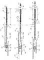
- FIG. 1A depicts a partial longitudinal section of an exemplary delivery system of the prior art for deploying a foreshortening-prone stent of the prior art
- FIG. 1B depicts the delivery system of FIG. 1A in a partially deployed configuration
- FIG. 1C depicts the delivery system of FIG. 1A after the stent has been fully deployed
- FIG. 2A depicts a partial longitudinal section of an exemplary delivery system of the present invention
- FIG. 2B depicts the delivery system of FIG. 2A in a partially deployed configuration
- FIG. 2C depicts the delivery system of FIG. 2A after the stent has been fully deployed
- FIG. 3A is a proximal view of an exemplary embodiment wherein the pinions shown in FIG. 2A have a dial rotationally interlocked to them;
- FIG. 3B is a proximal view of an exemplary embodiment wherein the pinions shown in FIG. 2A have a crank rotationally interlocked to them;
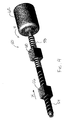
- FIG. 4 is a perspective view of an exemplary linkage comprising a screw drive and a pair of travelers;
- FIG. 5 is a cross-sectional view of a portion of an exemplary delivery system having a clutch mechanism
- FIG. 6 depicts a partial longitudinal section of an exemplary delivery system of the present invention having a lag mechanism.
- Delivery system 30 comprises stent 10 in its compressed configuration, outer sheath 28 that radially surrounds the stent, pusher 27 positioned at the proximal end 11 of the stent, and a linkage 32 in communication with both the pusher and the outer sheath.
- Linkage 32 coordinates proximal retraction of outer sheath 28 with simultaneous distal advancement of pusher 27 .
- inner member 26 is also shown in FIGS. 2 A- 2 C , attached to an interface 42 at its proximal end and extending axially through stent 10 and pusher 27 to a connection with tip 24 at its distal end.
- linkage 32 comprises a rack and pinion system having intermeshing teeth 33 .
- the rack and pinion system comprises a first rack 34 in linear communication with outer sheath 28 , a second rack 36 in linear communication with the pusher 27 , and a pair of rotationally-interlocked pinions 38 and 39 supported between the first rack and the second rack.
- Pinion 38 has a first diameter D 1 and is adapted to interface with the rack 34 .
- Pinion 39 has a second diameter D 2 that is relatively smaller than first diameter D 1 , and is adapted to interface with the rack 36 . It should be noted that the rack and pinion system shown in FIGS.
- the pinions may have a common diameter and may be mounted on separate shafts, with a gear mechanism, belt and sheave, or chain and sprocket mechanism provided between the pinions to provide the differential motion between the racks.
- linkage is used herein to denote any mechanism that links together the motion of outer sheath 28 and pusher 27 .
- linkages may be provided within the scope of this invention, including but not limited to those discussed specifically herein below.
- each rack 34 and 36 moves linearly in concert with the sheath 28 or the pusher 27 , respectively, such that movement of the respective rack in one linear direction will move the sheath or pusher in the same linear direction.
- rack 34 is shown with a direct connection to sheath 28 at interface 40
- rack 36 is shown with a direct connection to pusher 27 at interface 42 in FIGS. 2 A- 2 C
- the respective racks may be indirectly connected to the sheath or pusher through one or more intermediate elements.
- the terminology “in linear communication with” has been chosen to reflect that no direct connection between the racks and the sheath or pusher is required.
- interfaces 40 and 42 are configured to be attached to sheath 28 and pusher 27 at a location such that the interfaces and linkage 32 can remain outside of the body lumen during deployment.
- pinions 38 and 39 are connected in such a way that they rotate the same degree of revolution in the same direction simultaneously.
- the pinions are mounted on the same shaft 44 in a way that one full revolution of the shaft will coincide with one full revolution of both pinions 38 and 39 .
- the pinions may be bonded together or may be machined from a single integral piece, or the shaft may be keyed and each pinion may be independent from one other but keyed similarly to the shaft.
- the pinions may be mounted on separate shafts, with other methods of rotationally interlocking them, such as a gear train or drive belt or chain that provides for one full revolution of one pinion to translate to one full revolution of the other pinion. It should be understood that any number of mechanisms may be devised for providing rotationally interlocking pinions, all of which are within the scope of the present invention.
- the simultaneous retraction of outer sheath 28 and advancement of pusher 27 may be accomplished by any of a number of methods and structures, some examples of which are shown in FIG. 2B with dashed lines, and in FIGS. 3A and 3B.
- a handle 122 may be attached to rack 34 or otherwise in linear communication with outer sheath 28 so that proximal retraction of the handle actuates the linkage.
- a slide 46 may be attached to rack 36 or otherwise in linear communication with pusher 27 , so that distal advancement of the slide will actuate the linkage.
- handle 122 and slide 46 are both shown in FIG. 2B, embodiments of the invention may have none, both, or only one of these means.
- a member in rotational communication with pinions 38 and 39 may also or instead be used for directly rotating at least one of the pinions, thereby actuating the linkage.
- Suitable members are not limited to dial 48 and crank 49 , but may include any means known in the art for actuating a pinion, such as for example but not limited to, a pistol grip mechanism such as disclosed in U.S. Pat. No. 5,968,052 to Sullivan and DeVries, incorporated herein by reference.
- in rotational communication” with pinions 38 and 39 it is meant that rotation of the member also causes pinions 38 and 39 to rotate.
- a full revolution of the first member may translate to less than, equal to, or greater than a full revolution of a second member in rotational communication with the first member.
- a dial or crank may be rotationally interlocked to the pinions as shown in FIGS. 3A and 3B so that one revolution of the dial or crank corresponds to one rotation of the pinions, or the dial or crank may include a transmission such as a gearing mechanism that provides mechanical advantage, such as for example a dial geared to the pinion such that a full rotation of the dial results in less than a full rotation of the pinion.
- the transmission may translate less than a full rotation of the dial to a full rotation of the pinion.
- the diameter of the dial or diameter of rotation of the crank may also be used to provide mechanical advantage or to reduce travel.
- the “diameter of rotation” for a crank is twice the radial distance r 1 of the crank from the centerpoint of the shaft rotated by the crank, as shown in FIG. 3B.
- dial 48 may have a diameter D 3 or crank 49 may have a diameter of rotation 2 r 1 greater than diameter D 1 of the largest pinion, as shown in FIGS. 3A and 3B, respectively.
- the larger diameter provides mechanical advantage.
- a dial with a diameter smaller than diameter D 1 enables the user to retract outer sheath 28 a given linear distance greater than ⁇ D 3 by moving the dial a circumferential distance ⁇ D 3 , where ⁇ is the percentage of a full revolution traveled by dial 48 .
- FIG. 4 there is shown an alternative linkage embodiment 50 of the present invention comprising a screw shaft 52 having a first threaded flight 54 for engaging a first traveler 56 , and a second threaded flight 58 for engaging a second traveler 60 .
- a handle 62 may be used for manipulating the linkage.
- flight 54 moves traveler 56 in the direction of arrow X
- flight 58 moves traveler 60 in the direction opposite arrow X.
- flight 54 has a wider pitch than flight 58 , so that traveler 56 moves a greater distance that traveler 60 .
- screw shaft 52 may be engaged by a transmission for translating linear motion in any plane or rotational motion about any axis to rotational motion of screw shaft 52 , with or without mechanical advantage, including engagement by, for example, the pistol grip mechanism referred to herein.
- a preferred embodiment is for the linkage to coordinate a first distance (d 1 ) of proximal retraction of the outer sheath to a second distance (d 2 ) of distal advancement of the pusher.
- d 1 first distance
- d 2 second distance
- FIG. 2C outer sheath 28 needs to retract a distance d 1 equal to the expanded length (L E ) of stent 10 .
- pusher 27 needs only to travel a distance d 2 equal to the compressed length (L C ) minus the expanded length (L E ). Therefore the ratio of the second distance to the first distance ( d 2 d 1 )
- the gear ratio D 2 /D 1 is also preferably equal to the foreshortening ratio.
- P 1 the pitch of flight 54 represented as a number of turns per unit length
- P 2 the corresponding pitch of flight 58 .
- the distance d 1 n/P 1
- n the number of full turns of handle 62
- d 2 n/P 2 .
- the ratio of P 1 /P 2 is equal to the foreshortening ratio d 2 /d 1 .
- the linkages of the present invention may comprise a separable component from the component comprising the outer sheath and pusher, or an inseparable component.
- the linkage component may be described as a “manipulator” for a delivery system because it is used to manipulate the delivery system during deployment.
- the manipulator may comprise other components in addition to the linkage, but at a minimum, referring to the embodiment shown in FIGS. 2 A- 2 C, the manipulator comprises linkage 32 , interface 40 for connecting the manipulator in communication with the outer sheath 28 , interface 42 for connecting the manipulator in communication with pusher 27 , and means for actuating the linkage.
- the means for actuating the linkage may be any means known in the art, particularly those discussed above such as handle 122 or slide 46 as shown in FIG. 2B, or dial 48 or crank 49 as shown in FIGS. 3A and 3B, respectively.
- a rack and pinion type linkage is shown herein by way of example, any type of linkage known in the art may be used, such as a belt and pulley system.
- the manipulator is detachable from the rest of the delivery system, it may also be reusable.
- hospitals may heat items to be sterilized in an autoclave set to an effective temperature for an effective amount of time known to sterilize the items.
- the combination of time and temperature is well-known in the art, as are materials of construction suitable for items that undergo such sterilization procedures.
- Stainless steel is a typical material used, but the invention is not limited to any particular material, and therefore any suitable material known in the art may be used.
- Manipulators not intended for reuse may comprise materials less expensive than stainless steel, as are known in the art, including materials such as plastics that can readily be incinerated in hospital incinerators. Although non-reusable manipulators may still be detachable if desired, for example for shipping or packaging considerations, manipulators that are integral to the rest of the stent delivery system may offer an advantageous reduction in assembly time and correspondingly reduced potential for assembly errors or failures at the interfaces.
- the delivery system of the present invention lends provides a unique method for delivery of an endoluminal device.
- the method comprises the steps of first introducing the delivery system into a body lumen and aligning the first end of the endoluminal device to be deployed, which in FIG. 2A is the distal end 12 , with a desired target location 29 on the lumen or a previously endoluminal device (not shown).
- the method then comprises deploying the endoluminal device with the second end in the desired target location by manipulating the linkage to move the outer sheath in a first direction while simultaneously moving the pusher in a second direction opposite the first direction.
- the stent is being deployed from a proximal location outside the lumen into a distal location, and the outer sheath is proximally retracted while the pusher is distally advanced
- the method is not limited to any particular direction of deployment.
- the step of manipulating the linkage may be initiated by retracting handle 122 or advancing slide 46 as shown in FIG. 2B, by turning dial 48 or crank 49 as shown in FIGS. 3A and 3B, respectively, or by any other means.
- the linkage may be manipulated using less force than the sum of forces required to move the outer sheath and the pusher without the linkage.
- the method may be useful for the implantation of any endoluminal device, the method is particularly useful for an endoluminal device having a foreshortening ratio greater than 0.
- the method implants end 12 of the endoluminal device precisely at the desired target location 29 , unlike methods of the prior art where the foreshortening of the endoluminal device causes the distal end to be implanted proximally of the desired target location.
- the preferred method coordinating a first distance of proximal retraction (d 1 ) of outer sheath 28 with a second distance (d 2 ) of distal advancement of pusher 27 wherein the second distance divided by the first distance ( d 2 d 1 )
- [0050] is approximately equal to the foreshortening ratio of the endoluminal device. It should be appreciated that although the illustrations and accompanying text herein refer to a stent, the introducer of the present invention may be used for deploying any type of endoluminal device, including but not limited to stents, grafts, prostheses, vena cava filters, and the like.
- the method further comprises attaching the first component to the sheath and pusher component prior to introducing the stent delivery system into the lumen.
- the linkage component is reusable, the method further comprises the steps of detaching the second component from the first component after deployment of the stent and then sterilizing the linkage component.
- Some stent or filter embodiments may comprise a combination of foreshortening and non-foreshortening sections.
- deployment of one longitudinal section of the stent may benefit from the linkage between pusher and outer sheath as discussed above, whereas deployment of an adjacent longitudinal section may not benefit from such a linkage, and may actually suffer from use of such system.
- the system may have structure features tailored to prevent advancement of the pusher simultaneously with retraction of the outer sheath at certain points during deployment. Exemplary such systems are described below, but the invention is not limited to any particular embodiment of these functionalities.
- System 500 comprises a two part casing 502 , comprising snap-together halves 502 a and 502 b .
- Ball bearing 504 having balls 503 is attached to half 502 a , and shaft 44 is supported by the ball bearing.
- Spring 506 biases pinions 38 and 39 into a position in engagement with racks 34 and 36 , respectively.
- Clutch button 508 is biased by spring 510 outwardly from casing half 502 b , with stops 511 keeping the button from being fully ejected by the spring from the casing.
- Stops 511 may be set screws, a molded portion of the button, or any member functional to act as a stop but still provide for assembly of button 508 in the casing 502 .
- Depressing button 508 inwardly in the direction of arrow B causes the inward-most portion of prongs 509 of button 508 to engage pinion 39 and push both pinions out of engagement with the racks for as long as the clutch button is depressed.
- Releasing button 508 allows spring 506 to force the pinions back into engagement with the racks.
- Casing half 502 b has an indentation 514 concentric with button 508 so that button 508 can be depressed almost flush with casing 502 .
- Button 508 may be circular, square, or any shape desired.
- Prongs 509 may comprise prongs with circular or square cross-sections, circumferential portions of a cylinder, or any shape known in the art.
- Casing 502 is also shown with support brackets 512 for slidably supporting the racks.
- slidably supporting it is meant that the brackets do not interfere with the distal and proximal sliding of the racks.
- a casing that supports the pinion shaft and that has brackets to support the travel of the racks.
- Such a casing may be a complete enclosure as shown in FIG. 5, or may provide only enough structure to support the racks and/or pinions.
- the invention is not limited to the particular features of the casing, nor to embodiments having casings.
- FIGS. 2 A- 4 For simplicity of illustration.
- Such supportive features may comprise any structural elements known in the art.
- FIG. 6 illustrates an exemplary lag system 600 .
- Lag system 600 comprises features similar to those found in FIGS. 2 A- 2 C, except that a longitudinal portion 602 of rack 634 is without teeth 33 .
- rack 634 attached to outer sheath 28 is retracted over portion 602 , there is nothing to engage pinion 38 , and thus neither pinion 39 or 38 rotate until the proximal-most tooth 33 a of rack 634 engages pinion 38 .
- distal advancement of pusher 27 can be said to “lag” the proximal retraction of sheath 28 .
- Toothless portion 602 may be tailored to have a length sufficient to deploy the corresponding non-foreshortening portion of the endoluminal device to be deployed.
- the toothless portion may also be on one of both of the pinions, if the conditions favor such an arrangement. Where the pinions experience more than a single revolution over the course of fully deploying the endoluminal device, however, a toothless portion of the rack may be most advantageous.
- the toothless portion 602 may be at the proximal end of the rack, a distal end of the rack, or in the middle of the rack, and the rack may have more than one toothless portion.
- the structural features of the lag system are preferably tailored to match the features of the endoluminal device to be deployed.
- the rack can be designed so that the practitioner merely pulls proximally on rack 634 , without having to be concerned about timing the engagement and release of the clutch.
- the rack may be provided with indicia visible to the practitioner at the proximal end to indicate when to pull in the clutch and when to release.
- a portion proximally protruding from the proximal end of the casing may comprise one color to indicate engaging the clutch and another color to indicate releasing the clutch.
- the color of the rack emerging from the casing may indicate to the practitioner whether to engage or release the clutch.
- dial 48 as shown in FIG. 3A may have color-coded portions or other indicia to indicate when to release and when to engage the clutch.
- the practitioner may be provided with instructions as to when to engage and disengage the clutch based on how many degrees the crank is turned.
- the pinions are typically the members with toothless portions.
- a lag system for the screw shaft embodiment shown in FIG. 4 can be approximated by having a very close pitch for a predetermined portion of one of the flights.
Abstract
Description
- This invention relates generally to delivery systems for endoluminal devices, and, more specifically, to delivery systems for endoluminal devices that undergo a decrease in length when being expanded from a radially compressed configuration.
- Endoluminal devices comprise the general category of devices, such as stents, grafts, combinations thereof commonly referred to as stent-grafts or endoluminal prostheses, vena cava filters, and the like, that may be implanted in a body lumen. Endoluminal devices may be implanted by so-called “minimally invasive techniques” in which the prosthesis, restrained in a radially compressed configuration by a sheath or catheter, is delivered by a deployment system or “introducer” to the site where it is required. The introducer may enter the body through the patient's skin, or by a “cut down” technique in which the entry lumen, such as a blood vessel, is exposed by minor surgical means. When the introducer has been threaded into the body lumen to the prosthesis deployment location, the introducer is manipulated to cause the endoluminal device to be ejected from the surrounding sheath or catheter in which it is restrained (or alternatively the surrounding sheath or catheter is retracted from the endoluminal device), whereupon the endoluminal device expands to a predetermined diameter at the deployment location, and the introducer is withdrawn.
- As referred to herein, “distal” refers to the direction further away from the insertion point and “proximal” refers to the direction closer to the insertion point. Endoluminal devices, such as stents and vena cava filters, may expand by spring elasticity, balloon expansion, or by the self-expansion of a thermally or stress-induced return of a memory material to a pre-conditioned expanded configuration.
- Various types of endoluminal device architectures, are known in the art, including many designs comprising a filament or number of filaments, such as a wire or wires, wound or braided into a particular configuration. Included among these configurations are braided stents, such as is described in U.S. Pat. No. 4,655,771 to Hans I. Wallsten and incorporated herein by reference; the '771 Wallsten patent is only one example of many variations of braided architecture known in the art and thus is not intended as a limitation of the invention described herein later. Braided endoluminal devices tend to be very flexible, having the ability to be placed in tortuous anatomy and still maintain patency. The flexibility of braided stents make them particularly well-suited for treating aneurysms in the aorta, where often the lumen of the vessel becomes contorted and irregular both before and after placement of the stent.
- Many braided endoluminal devices experience “foreshortening” when deployed in a body lumen. Referring now to FIGS. 1A-1C, showing an
exemplary delivery system 20 of the prior art,stent 10 may have a first length LC when radially compressed as shown in FIG. 1A and a second, shorter length LE when radially expanded, as shown in FIG. 1C. The “foreshortening ratio”
- can be used as a measure of the relative change in length. Braided endoluminal devices typically have a relatively large foreshortening ratio as compared to non-braided endoluminal devices. The foreshortening ratio is a function of compressed diameter, deployed diameter, and the braid angle. If these variables are known, the endoluminal device has a predictable foreshortening ratio.
- Foreshortening may affect the deployment accuracy of endoluminal devices. Describing
delivery system 20 now in more detail, the delivery system comprises ahandle 22, atip 24, aninner member 26 attached to the tip and the handle, apusher 27 positioned proximally ofstent 10, and anouter sheath 28 slidable relative to the inner member and pusher.Inner member 26 may have one ormore protrusions 25 thereon for engaging the stent during deployment, such as are disclosed in U.S. patent application Ser. No. 09/574,418, filed May 19, 2000, by Sullivan et al., incorporated herein by reference.Stent 10 may be a braided stent having awound end 11, such as is described in U.S. patent application Ser. No. 09/442,165, filed Nov. 16, 1999, by Chouinard et al. and incorporated herein by reference.Delivery system 20 is maneuvered into the body lumen (not shown) so that thedistal end 12 ofstent 10 is aligned with a desired deployment location 29 in the lumen, as shown in FIG. 1A. FIGS. 1A-1C are shown in vertical alignment with one another on the page so that desired deployment location 29 is in the same horizontal position in all figures for illustrative purposes. - To deploy the stent,
outer sheath 28 is retracted in the direction of arrow A as shown in FIG. 1B. Asstent 10 begins to deploy, it also foreshortens, causingdistal end 12 ofstent 10 to be move proximally from the desired deployment location 29. Thus, after full deployment as shown in FIG. 1C, continued foreshortening during deployment may cause the ultimate resting position ofdistal end 12 to be a distance dL from the desired deployment location 29. This distance dL is typically approximately the difference in length between the radially compressed length LC and the expanded length LE. In some cases,distal end 12 ofstent 10 may frictionally engage a portion of the body lumen in which the stent is being deployed before the stent is completely deployed. In such cases, a portion of the length accounting for the difference between the compressed length LC and the expanded length LE of the stent will be proximal to the deployed stent. Thus, even though this distance may be predictable, practitioners must determine the correct place to start deployment based upon where the end of the stent is expected to land after foreshortening. Deploying such stents with accuracy, therefore, takes repeated practice and is prone to error. - It is therefore desirable to minimize the impact of foreshortening of braided endoluminal devices during deployment so that such endoluminal devices can be more accurately deployed.
- One aspect of the invention comprises a delivery system for an endoluminal device, such as a vena cava filter, or stent, graft, or combination thereof. The delivery system comprises an endoluminal device having a compressed configuration, an outer sheath that radially surrounds the endoluminal device in its compressed configuration, a pusher positioned at one end of the endoluminal device, and a linkage between the pusher and the outer sheath that coordinates movement of the outer sheath in a first direction with simultaneous movement of the pusher in a second direction opposite the first direction. This delivery system is particularly useful for endoluminal devices having a compressed length (L C), an expanded length (LE), and a foreshortening ratio

- greater than 0. In such an embodiment, the linkage preferably coordinates a first distance of proximal retraction (d 1) of the outer sheath with a second distance (d2) of distal advancement of the pusher, so that the second distance divided by the first distance

- is approximately equal to the foreshortening ratio. The linkage may provide mechanical advantage that enables a user to manipulate the linkage using less force than is required to simultaneously move the outer sheath in the first direction and the pusher in the second direction.
- In one aspect of the invention, the linkage may comprise a rack and pinion system. The rack and pinion system comprises a first rack in communication with the outer sheath, a second rack in linear communication with the pusher, and a pair of rotationally-interlocked pinions supported between the first rack and the second rack. The pair of rotationally-interlocked pinions comprise a first pinion having a first diameter adapted to interface with the first rack and a second pinion having a second, relatively smaller diameter adapted to interface with the second rack. A member, such as a dial with a larger diameter than the first pinion, may be rotationally interlocked to the pinions for rotating the pinions to cause the outer sheath and the pusher to simultaneously move. The system may comprise a casing disposed about the linkage, and a bearing in the casing for supporting a shaft on which the pinions are mounted.
- In another aspect of the invention, the linkage comprises a screw shaft having a first threaded flight having a first pitch and a second threaded flight having a second pitch. A first traveler is engaged by the first threaded flight and in linear communication with the outer sheath. A second traveler is engaged by the second threaded flight and in linear communication with the pusher. The linkage further comprises means for turning the screw shaft. Where the first threaded flight has a first pitch (P 1) corresponding to a number of turns per unit length and a second threaded flight having a second corresponding pitch (P2), the ratio of the first pitch to the second pitch (P1/P2) is approximately equal to the foreshortening ratio.
- In some embodiments of the invention, the delivery system may further comprise a clutch mechanism for preventing simultaneous movement of the outer sheath and the pusher when engaged, including, optionally, indicia for indicating to a user of the delivery system when to engage or disengage the clutch mechanism. Other embodiments may comprise a lag mechanism for preventing simultaneous movement of the outer sheath and the pusher over a predetermined travel distance of the outer sheath.
- Another aspect of the invention comprises a manipulator for a delivery system comprising an outer sheath that radially surrounds a compressed endoluminal device and a pusher positioned at one end of the endoluminal device. The manipulator comprises a first interface for connecting the manipulator in communication with the outer sheath, a second interface for connecting the manipulator in communication with the pusher, a linkage coupled to the first and second interface for coordinating movement of the outer sheath in a first direction with simultaneous movement of the pusher in a second direction opposite the first direction, and means for actuating the linkage. The manipulator may be detachable from the delivery system and reusable, in which case the manipulator comprises a material of construction, such as but not limited to stainless steel, adapted to withstand prolonged exposure to high temperatures effective to sterilize the manipulator without being damaged.
- Still another aspect of the invention comprises a method for endoluminal deployment of an endoluminal device. The method comprises first introducing a delivery system from a first location outside a lumen to a second location inside the lumen. The delivery system comprises an endoluminal device in a compressed configuration, an outer sheath that radially surrounds the endoluminal device in the compressed configuration, a pusher positioned at a first end of the endoluminal device, and a linkage in communication with the pusher and the outer sheath for coordinating simultaneous movement of the outer sheath and the pusher. The second location is a location at which a second end of the endoluminal device is axially aligned with a desired target location on the lumen. The method next comprises deploying the endoluminal device so that the second end is implanted in the desired target location. This is effected by manipulating the linkage to move the outer sheath in a first direction while simultaneously moving the pusher in a second direction opposite the first direction.
- Where the first location outside the lumen is a proximal location, the second location is a distal location, the first direction is a proximal direction and the second direction is a distal direction, the step of deploying the endoluminal device may comprise proximally retracting a handle in communication with the outer sheath or distally advancing a slide in communication with the pusher. Where the linkage comprises a rack and pinion system, the step of deploying the endoluminal device may comprise manipulating a member that is rotationally interlocked with the pinion. Where the stent delivery system comprises a first component comprising the outer sheath and the pusher and a second, detachable component comprising the linkage, the method may comprise attaching the first component to the second component before introducing the delivery system into the lumen. Similarly, the method may comprise the steps of detaching the second component from the first component after deployment of the endoluminal device and then sterilizing the second component so that it can be reused.
- In an embodiment wherein the endoluminal device has a foreshortening ratio greater than zero in the first portion and the foreshortening ratio equal to zero in a second portion and the system further comprises a clutch mechanism for preventing simultaneous movement of the outer sheath and the pusher when engaged, the method comprises deploying the first portion of the endoluminal device with the clutch engaged so that there is not simultaneous movement of the outer sheath and the pusher, and deploying the second portion of the endoluminal device with the clutch released so that there is simultaneous movement of the outer sheath and the pusher. In an embodiment wherein the endoluminal device has a foreshortening ratio greater than zero in a first portion and a foreshortening ratio equal to zero in a second portion and the system comprises a lag mechanism for preventing simultaneous movement of the outer sheath and the pusher over a predetermined travel distance of the outer sheath, the method comprises deploying the first portion of the endoluminal device without simultaneous movement of the outer sheath and the pusher and deploying the second portion of the endoluminal device with simultaneous movement of the outer sheath and the pusher.
- It is to be understood that both the foregoing general description and the following detailed description are exemplary, but are not restrictive, of the invention.
- The invention is best understood from the following detailed description when read in connection with the accompanying drawing. It is emphasized that, according to common practice, the various features of the drawing are not to scale. On the contrary, the dimensions of the various features are arbitrarily expanded or reduced for clarity. Included in the drawing are the following figures:
- FIG. 1A depicts a partial longitudinal section of an exemplary delivery system of the prior art for deploying a foreshortening-prone stent of the prior art;
- FIG. 1B depicts the delivery system of FIG. 1A in a partially deployed configuration;
- FIG. 1C depicts the delivery system of FIG. 1A after the stent has been fully deployed;
- FIG. 2A depicts a partial longitudinal section of an exemplary delivery system of the present invention;
- FIG. 2B depicts the delivery system of FIG. 2A in a partially deployed configuration;
- FIG. 2C depicts the delivery system of FIG. 2A after the stent has been fully deployed;
- FIG. 3A is a proximal view of an exemplary embodiment wherein the pinions shown in FIG. 2A have a dial rotationally interlocked to them;
- FIG. 3B is a proximal view of an exemplary embodiment wherein the pinions shown in FIG. 2A have a crank rotationally interlocked to them;
- FIG. 4 is a perspective view of an exemplary linkage comprising a screw drive and a pair of travelers;
- FIG. 5 is a cross-sectional view of a portion of an exemplary delivery system having a clutch mechanism; and
- FIG. 6 depicts a partial longitudinal section of an exemplary delivery system of the present invention having a lag mechanism.
- The invention will next be illustrated with reference to the figures wherein similar numbers indicate the same elements in all figures. Such figures are intended to be illustrative rather than limiting and are included herewith to facilitate the explanation of the apparatus of the present invention.
- Referring now to FIGS. 2A-2C, there is shown an
exemplary delivery system 30 of this invention in various stages of deployment.Delivery system 30 comprisesstent 10 in its compressed configuration,outer sheath 28 that radially surrounds the stent,pusher 27 positioned at theproximal end 11 of the stent, and alinkage 32 in communication with both the pusher and the outer sheath.Linkage 32 coordinates proximal retraction ofouter sheath 28 with simultaneous distal advancement ofpusher 27. Also shown in FIGS. 2A-2C isinner member 26, attached to aninterface 42 at its proximal end and extending axially throughstent 10 andpusher 27 to a connection withtip 24 at its distal end. - As shown in FIGS. 2A-2C,
linkage 32 comprises a rack and pinion system having intermeshingteeth 33. The rack and pinion system comprises afirst rack 34 in linear communication withouter sheath 28, asecond rack 36 in linear communication with thepusher 27, and a pair of rotationally-interlockedpinions Pinion 38 has a first diameter D1 and is adapted to interface with therack 34.Pinion 39 has a second diameter D2 that is relatively smaller than first diameter D1, and is adapted to interface with therack 36. It should be noted that the rack and pinion system shown in FIGS. 2A-2C is merely one exemplary embodiment, and other rack and pinion systems may also be devised to provide a similar effect. For example, the pinions may have a common diameter and may be mounted on separate shafts, with a gear mechanism, belt and sheave, or chain and sprocket mechanism provided between the pinions to provide the differential motion between the racks. - The term “linkage” is used herein to denote any mechanism that links together the motion of
outer sheath 28 andpusher 27. Thus, although a rack and pinion system is shown herein, other types of linkages may be provided within the scope of this invention, including but not limited to those discussed specifically herein below. - By “in linear communication with” it is meant that the each
rack sheath 28 or thepusher 27, respectively, such that movement of the respective rack in one linear direction will move the sheath or pusher in the same linear direction. Althoughrack 34 is shown with a direct connection tosheath 28 atinterface 40 andrack 36 is shown with a direct connection topusher 27 atinterface 42 in FIGS. 2A-2C, the respective racks may be indirectly connected to the sheath or pusher through one or more intermediate elements. Thus, the terminology “in linear communication with” has been chosen to reflect that no direct connection between the racks and the sheath or pusher is required. Preferably, interfaces 40 and 42 are configured to be attached tosheath 28 andpusher 27 at a location such that the interfaces andlinkage 32 can remain outside of the body lumen during deployment. - By “rotationally interlocked” it is meant that pinions 38 and 39 are connected in such a way that they rotate the same degree of revolution in the same direction simultaneously. For example, as shown in FIGS. 2A-2C, the pinions are mounted on the
same shaft 44 in a way that one full revolution of the shaft will coincide with one full revolution of bothpinions - The simultaneous retraction of
outer sheath 28 and advancement ofpusher 27 may be accomplished by any of a number of methods and structures, some examples of which are shown in FIG. 2B with dashed lines, and in FIGS. 3A and 3B. As shown in FIG. 2B, ahandle 122 may be attached to rack 34 or otherwise in linear communication withouter sheath 28 so that proximal retraction of the handle actuates the linkage. Similarly, aslide 46 may be attached to rack 36 or otherwise in linear communication withpusher 27, so that distal advancement of the slide will actuate the linkage. Although both handle 122 and slide 46 are both shown in FIG. 2B, embodiments of the invention may have none, both, or only one of these means. A member in rotational communication withpinions dial 48 shown in FIG. 3A or crank 49 shown in FIG. 3B, may also or instead be used for directly rotating at least one of the pinions, thereby actuating the linkage. Suitable members are not limited to dial 48 and crank 49, but may include any means known in the art for actuating a pinion, such as for example but not limited to, a pistol grip mechanism such as disclosed in U.S. Pat. No. 5,968,052 to Sullivan and DeVries, incorporated herein by reference. By “in rotational communication” withpinions pinions - Accordingly, a dial or crank may be rotationally interlocked to the pinions as shown in FIGS. 3A and 3B so that one revolution of the dial or crank corresponds to one rotation of the pinions, or the dial or crank may include a transmission such as a gearing mechanism that provides mechanical advantage, such as for example a dial geared to the pinion such that a full rotation of the dial results in less than a full rotation of the pinion. Conversely, if it is desired to reduce the amount of travel of the dial relative to the pinion, the transmission may translate less than a full rotation of the dial to a full rotation of the pinion. The diameter of the dial or diameter of rotation of the crank may also be used to provide mechanical advantage or to reduce travel. The “diameter of rotation” for a crank is twice the radial distance r 1 of the crank from the centerpoint of the shaft rotated by the crank, as shown in FIG. 3B. For example, dial 48 may have a diameter D3 or crank 49 may have a diameter of rotation 2 r 1 greater than diameter D1 of the largest pinion, as shown in FIGS. 3A and 3B, respectively. Where the dial is rotationally interlocked with the pinions, the larger diameter provides mechanical advantage. Conversely, a dial with a diameter smaller than diameter D1 enables the user to retract outer sheath 28 a given linear distance greater than ΦπD3 by moving the dial a circumferential distance ΦπD3, where Φ is the percentage of a full revolution traveled by
dial 48. - Referring now to FIG. 4, there is shown an
alternative linkage embodiment 50 of the present invention comprising a screw shaft 52 having a first threadedflight 54 for engaging afirst traveler 56, and a second threadedflight 58 for engaging a second traveler 60. Ahandle 62 may be used for manipulating the linkage. As shown in FIG. 4, whenhandle 62 is turned clockwise (as viewed from the handle end of the screw) in the direction of arrow Z,flight 54 movestraveler 56 in the direction of arrow X, whereasflight 58 moves traveler 60 in the direction opposite arrow X. Furthermore,flight 54 has a wider pitch thanflight 58, so thattraveler 56 moves a greater distance that traveler 60. Although illustrated herein with asingle handle 62 that may be turned by the user, it should be recognized that any means for rotating screw shaft 52 may be provided. For example, screw shaft 52 may be engaged by a transmission for translating linear motion in any plane or rotational motion about any axis to rotational motion of screw shaft 52, with or without mechanical advantage, including engagement by, for example, the pistol grip mechanism referred to herein. - For any type of linkage used in the present invention, a preferred embodiment is for the linkage to coordinate a first distance (d 1) of proximal retraction of the outer sheath to a second distance (d2) of distal advancement of the pusher. As shown in FIG. 2C,
outer sheath 28 needs to retract a distance d1 equal to the expanded length (LE) ofstent 10. By contrast,pusher 27 needs only to travel a distance d2 equal to the compressed length (LC) minus the expanded length (LE). Therefore the ratio of the second distance to the first distance
- is equal to the foreshortening ratio.
- For the rack and pinion system shown in FIGS. 2A-2C, the circumferential travel ΦπD1 of
pinion 38 translates to distance d1 and the circumferential travel ΦπD2 ofpinion 39 translates to distance d2 for an appropriate value of Φ. Accordingly, the gear ratio D2/D1 is also preferably equal to the foreshortening ratio. Similarly, for thescrew drive embodiment 50 shown in FIG. 4, where P1 equals the pitch offlight 54 represented as a number of turns per unit length and P2 equals the corresponding pitch offlight 58. Thus, the distance d1=n/P1, where n is the number of full turns ofhandle 62, and d2=n/P2. Accordingly, the ratio of P1/P2 is equal to the foreshortening ratio d2/d1. - The linkages of the present invention may comprise a separable component from the component comprising the outer sheath and pusher, or an inseparable component. As such, the linkage component may be described as a “manipulator” for a delivery system because it is used to manipulate the delivery system during deployment. The manipulator may comprise other components in addition to the linkage, but at a minimum, referring to the embodiment shown in FIGS. 2A-2C, the manipulator comprises
linkage 32,interface 40 for connecting the manipulator in communication with theouter sheath 28,interface 42 for connecting the manipulator in communication withpusher 27, and means for actuating the linkage. The means for actuating the linkage may be any means known in the art, particularly those discussed above such ashandle 122 or slide 46 as shown in FIG. 2B, or dial 48 or crank 49 as shown in FIGS. 3A and 3B, respectively. Finally, although a rack and pinion type linkage is shown herein by way of example, any type of linkage known in the art may be used, such as a belt and pulley system. - Where the manipulator is detachable from the rest of the delivery system, it may also be reusable. In such embodiments, it is desirable for the manipulator to comprise a material of construction adapted to withstand exposure to a predetermined temperature for a predetermined amount of time effective to sterilize the manipulator without the manipulator being damaged. For example, hospitals may heat items to be sterilized in an autoclave set to an effective temperature for an effective amount of time known to sterilize the items. The combination of time and temperature is well-known in the art, as are materials of construction suitable for items that undergo such sterilization procedures. Stainless steel is a typical material used, but the invention is not limited to any particular material, and therefore any suitable material known in the art may be used.
- Manipulators not intended for reuse may comprise materials less expensive than stainless steel, as are known in the art, including materials such as plastics that can readily be incinerated in hospital incinerators. Although non-reusable manipulators may still be detachable if desired, for example for shipping or packaging considerations, manipulators that are integral to the rest of the stent delivery system may offer an advantageous reduction in assembly time and correspondingly reduced potential for assembly errors or failures at the interfaces.
- The delivery system of the present invention lends provides a unique method for delivery of an endoluminal device. The method comprises the steps of first introducing the delivery system into a body lumen and aligning the first end of the endoluminal device to be deployed, which in FIG. 2A is the
distal end 12, with a desired target location 29 on the lumen or a previously endoluminal device (not shown). The method then comprises deploying the endoluminal device with the second end in the desired target location by manipulating the linkage to move the outer sheath in a first direction while simultaneously moving the pusher in a second direction opposite the first direction. Although as shown in FIGS. 2A-2C, the stent is being deployed from a proximal location outside the lumen into a distal location, and the outer sheath is proximally retracted while the pusher is distally advanced, the method is not limited to any particular direction of deployment. The step of manipulating the linkage may be initiated by retractinghandle 122 or advancingslide 46 as shown in FIG. 2B, by turningdial 48 or crank 49 as shown in FIGS. 3A and 3B, respectively, or by any other means. Where the linkage provides mechanical advantage, the linkage may be manipulated using less force than the sum of forces required to move the outer sheath and the pusher without the linkage. - Although the method may be useful for the implantation of any endoluminal device, the method is particularly useful for an endoluminal device having a foreshortening ratio greater than 0. In such case, the method implants end 12 of the endoluminal device precisely at the desired target location 29, unlike methods of the prior art where the foreshortening of the endoluminal device causes the distal end to be implanted proximally of the desired target location. As discussed herein, the preferred method coordinating a first distance of proximal retraction (d1) of
outer sheath 28 with a second distance (d2) of distal advancement ofpusher 27 wherein the second distance divided by the first distance
- is approximately equal to the foreshortening ratio of the endoluminal device. It should be appreciated that although the illustrations and accompanying text herein refer to a stent, the introducer of the present invention may be used for deploying any type of endoluminal device, including but not limited to stents, grafts, prostheses, vena cava filters, and the like.
- Where the component comprising the linkage is detachable from at least the outer sheath and the pusher, the method further comprises attaching the first component to the sheath and pusher component prior to introducing the stent delivery system into the lumen. Wherein the linkage component is reusable, the method further comprises the steps of detaching the second component from the first component after deployment of the stent and then sterilizing the linkage component.
- Some stent or filter embodiments may comprise a combination of foreshortening and non-foreshortening sections. Thus, for example, deployment of one longitudinal section of the stent may benefit from the linkage between pusher and outer sheath as discussed above, whereas deployment of an adjacent longitudinal section may not benefit from such a linkage, and may actually suffer from use of such system. Thus, for this and other reasons, it may be desirable to provide a clutch mechanism that prevents engagement of the linkage when actuated. In other cases, the system may have structure features tailored to prevent advancement of the pusher simultaneously with retraction of the outer sheath at certain points during deployment. Exemplary such systems are described below, but the invention is not limited to any particular embodiment of these functionalities.
- Referring now to FIG. 5, there is shown a cross-sectional view of a portion of an exemplary delivery system 500 having a clutch mechanism. System 500 comprises a two
part casing 502, comprising snap-togetherhalves Ball bearing 504 havingballs 503 is attached tohalf 502 a, andshaft 44 is supported by the ball bearing. Although illustrated with a ball bearing, any type of bearing may be used.Spring 506 biases pinions 38 and 39 into a position in engagement withracks Clutch button 508 is biased byspring 510 outwardly from casinghalf 502 b, withstops 511 keeping the button from being fully ejected by the spring from the casing.Stops 511 may be set screws, a molded portion of the button, or any member functional to act as a stop but still provide for assembly ofbutton 508 in thecasing 502.Depressing button 508 inwardly in the direction of arrow B causes the inward-most portion ofprongs 509 ofbutton 508 to engagepinion 39 and push both pinions out of engagement with the racks for as long as the clutch button is depressed. Releasingbutton 508 allowsspring 506 to force the pinions back into engagement with the racks.Casing half 502 b has anindentation 514 concentric withbutton 508 so thatbutton 508 can be depressed almost flush withcasing 502.Button 508 may be circular, square, or any shape desired.Prongs 509 may comprise prongs with circular or square cross-sections, circumferential portions of a cylinder, or any shape known in the art. -
Casing 502 is also shown withsupport brackets 512 for slidably supporting the racks. By “slidably supporting” it is meant that the brackets do not interfere with the distal and proximal sliding of the racks. It should be understood that even embodiments without a clutch mechanism may have a casing that supports the pinion shaft and that has brackets to support the travel of the racks. Such a casing may be a complete enclosure as shown in FIG. 5, or may provide only enough structure to support the racks and/or pinions. The invention is not limited to the particular features of the casing, nor to embodiments having casings. It should be understood, however, that typically some structural element is present to support the pinions in the desired position relative to the racks, and such supportive features have been omitted from FIGS. 2A-4 for simplicity of illustration. Such supportive features may comprise any structural elements known in the art. - FIG. 6 illustrates an exemplary lag system 600. Lag system 600 comprises features similar to those found in FIGS. 2A-2C, except that a
longitudinal portion 602 ofrack 634 is withoutteeth 33. Thus, whenrack 634 attached toouter sheath 28 is retracted overportion 602, there is nothing to engagepinion 38, and thus neitherpinion proximal-most tooth 33 a ofrack 634 engagespinion 38. Thus, distal advancement ofpusher 27 can be said to “lag” the proximal retraction ofsheath 28.Toothless portion 602 may be tailored to have a length sufficient to deploy the corresponding non-foreshortening portion of the endoluminal device to be deployed. The toothless portion may also be on one of both of the pinions, if the conditions favor such an arrangement. Where the pinions experience more than a single revolution over the course of fully deploying the endoluminal device, however, a toothless portion of the rack may be most advantageous. Thetoothless portion 602 may be at the proximal end of the rack, a distal end of the rack, or in the middle of the rack, and the rack may have more than one toothless portion. The structural features of the lag system are preferably tailored to match the features of the endoluminal device to be deployed. - One advantage of a lag system over a clutch system, is that the rack can be designed so that the practitioner merely pulls proximally on
rack 634, without having to be concerned about timing the engagement and release of the clutch. For clutch systems, however, the rack may be provided with indicia visible to the practitioner at the proximal end to indicate when to pull in the clutch and when to release. For example, in the clutch system, asrack 34 is retracted, a portion proximally protruding from the proximal end of the casing may comprise one color to indicate engaging the clutch and another color to indicate releasing the clutch. Thus, as the rack is retracted, the color of the rack emerging from the casing may indicate to the practitioner whether to engage or release the clutch. Similarly, dial 48 as shown in FIG. 3A may have color-coded portions or other indicia to indicate when to release and when to engage the clutch. In a crank system, the practitioner may be provided with instructions as to when to engage and disengage the clutch based on how many degrees the crank is turned. It should be recognized that for lag systems to work with respect to the dial or crank embodiments of FIG. 3A or 3B, respectively, the pinions are typically the members with toothless portions. A lag system for the screw shaft embodiment shown in FIG. 4 can be approximated by having a very close pitch for a predetermined portion of one of the flights. - Although illustrated and described herein with reference to certain specific embodiments, the present invention is nevertheless not intended to be limited to the details shown. Rather, various modifications may be made in the details within the scope and range of equivalents of the claims and without departing from the spirit of the invention.
Claims (69)


Priority Applications (8)
| Application Number | Priority Date | Filing Date | Title |
|---|---|---|---|
| US10/115,669 US7052511B2 (en) | 2002-04-04 | 2002-04-04 | Delivery system and method for deployment of foreshortening endoluminal devices |
| DE60310392T DE60310392T2 (en) | 2002-04-04 | 2003-03-20 | System for introducing shortenable endoluminal devices |
| AT03746041T ATE347867T1 (en) | 2002-04-04 | 2003-03-20 | SYSTEM FOR DEPLOYING SHORTENABLE ENDOLUMINAL DEVICES |
| EP03746041A EP1494620B1 (en) | 2002-04-04 | 2003-03-20 | Delivery system for deployment of foreshortening endoluminal devices |
| JP2003581684A JP4448697B2 (en) | 2002-04-04 | 2003-03-20 | Delivery system for placement of shortening intraluminal devices |
| PCT/US2003/008436 WO2003084439A1 (en) | 2002-04-04 | 2003-03-20 | Delivery system for deployment of foreshortening endoluminal devices |
| CA2478474A CA2478474C (en) | 2002-04-04 | 2003-03-20 | Delivery system and method for deployment of foreshortening endoluminal devices |
| AU2003225873A AU2003225873A1 (en) | 2002-04-04 | 2003-03-20 | Delivery system for deployment of foreshortening endoluminal devices |
Applications Claiming Priority (1)
| Application Number | Priority Date | Filing Date | Title |
|---|---|---|---|
| US10/115,669 US7052511B2 (en) | 2002-04-04 | 2002-04-04 | Delivery system and method for deployment of foreshortening endoluminal devices |
Publications (2)
| Publication Number | Publication Date |
|---|---|
| US20030191516A1 true US20030191516A1 (en) | 2003-10-09 |
| US7052511B2 US7052511B2 (en) | 2006-05-30 |
Family
ID=28673812
Family Applications (1)
| Application Number | Title | Priority Date | Filing Date |
|---|---|---|---|
| US10/115,669 Expired - Lifetime US7052511B2 (en) | 2002-04-04 | 2002-04-04 | Delivery system and method for deployment of foreshortening endoluminal devices |
Country Status (8)
| Country | Link |
|---|---|
| US (1) | US7052511B2 (en) |
| EP (1) | EP1494620B1 (en) |
| JP (1) | JP4448697B2 (en) |
| AT (1) | ATE347867T1 (en) |
| AU (1) | AU2003225873A1 (en) |
| CA (1) | CA2478474C (en) |
| DE (1) | DE60310392T2 (en) |
| WO (1) | WO2003084439A1 (en) |
Cited By (219)
| Publication number | Priority date | Publication date | Assignee | Title |
|---|---|---|---|---|
| WO2005018498A1 (en) * | 2003-08-15 | 2005-03-03 | Boston Scientific Limited | Clutch driven stent delivery system |
| WO2005065200A2 (en) | 2003-12-23 | 2005-07-21 | Xtent, Inc. | Devices and methods for controlling and indicating the length of an interventional element |
| US20050273151A1 (en) * | 2004-06-04 | 2005-12-08 | John Fulkerson | Stent delivery system |
| US20060229634A1 (en) * | 2005-04-08 | 2006-10-12 | Shepherd David J | Methods and apparatus for inserting an intraocular lens into an eye |
| US20060229633A1 (en) * | 2005-04-08 | 2006-10-12 | Shepherd David J | Methods and apparatus for inserting an intraocular lens into an eye |
| US20070060999A1 (en) * | 2005-08-17 | 2007-03-15 | Michael Randall | Variable speed stent delivery system |
| US20070112373A1 (en) * | 2005-05-12 | 2007-05-17 | C.R. Bard Inc. | Removable embolus blood clot filter |
| US20070168020A1 (en) * | 2001-02-26 | 2007-07-19 | Brucker Gregory G | Bifurcated stent and delivery system |
| WO2007085373A1 (en) * | 2006-01-25 | 2007-08-02 | Jotec Gmbh | Insertion system for stents, comprising tension-compression kinematics |
| US20070219617A1 (en) * | 2006-03-17 | 2007-09-20 | Sean Saint | Handle for Long Self Expanding Stent |
| US20070255390A1 (en) * | 2006-04-27 | 2007-11-01 | William A. Cook Australia Pty. Ltd. | Rotary handle for controlled sequential deployment device |
| WO2007109621A3 (en) * | 2006-03-20 | 2008-02-14 | Xtent Inc | Apparatus and methods for deployment of linked prosthetic segments |
| US20080208209A1 (en) * | 2007-02-22 | 2008-08-28 | Heike Fischer | Device for delivering a self-expanding stent in a vessel of the body |
| US20090024133A1 (en) * | 2007-07-16 | 2009-01-22 | Fionan Keady | Delivery device |
| US20090187168A1 (en) * | 2008-01-18 | 2009-07-23 | Hoya Corporation | Slide member advancing/retracting mechanism |
| US20100070017A1 (en) * | 2008-09-16 | 2010-03-18 | Barthold Franz-Peter | Insertion system for deployment of catheter-based stent devices |
| US7704267B2 (en) | 2004-08-04 | 2010-04-27 | C. R. Bard, Inc. | Non-entangling vena cava filter |
| US7794473B2 (en) | 2004-11-12 | 2010-09-14 | C.R. Bard, Inc. | Filter delivery system |
| US7892273B2 (en) | 2001-12-03 | 2011-02-22 | Xtent, Inc. | Custom length stent apparatus |
| US7892274B2 (en) | 2001-12-03 | 2011-02-22 | Xtent, Inc. | Apparatus and methods for deployment of vascular prostheses |
| US7918881B2 (en) | 2003-06-09 | 2011-04-05 | Xtent, Inc. | Stent deployment systems and methods |
| US7938852B2 (en) | 2001-12-03 | 2011-05-10 | Xtent, Inc. | Apparatus and methods for delivery of braided prostheses |
| US20110190865A1 (en) * | 2010-01-29 | 2011-08-04 | Cook Medical Technologies Llc | Mechanically Expandable Delivery and Dilation Systems |
| US8016871B2 (en) | 2001-12-03 | 2011-09-13 | Xtent, Inc. | Apparatus and methods for delivery of multiple distributed stents |
| US8016870B2 (en) | 2001-12-03 | 2011-09-13 | Xtent, Inc. | Apparatus and methods for delivery of variable length stents |
| US8062344B2 (en) | 2001-04-30 | 2011-11-22 | Angiomed Gmbh & Co. Medizintechnik Kg | Variable speed self-expanding stent delivery system and luer locking connector |
| US8080048B2 (en) | 2001-12-03 | 2011-12-20 | Xtent, Inc. | Stent delivery for bifurcated vessels |
| US8083788B2 (en) | 2001-12-03 | 2011-12-27 | Xtent, Inc. | Apparatus and methods for positioning prostheses for deployment from a catheter |
| US20120022631A1 (en) * | 2010-07-21 | 2012-01-26 | Cook Medical Technologies Llc | Control System for a Stent Delivery System |
| US20120041261A1 (en) * | 2009-03-25 | 2012-02-16 | Terumo Kabushiki Kaisha | Balloon catheter and balloon catheter assembly |
| US8177831B2 (en) | 2001-12-03 | 2012-05-15 | Xtent, Inc. | Stent delivery apparatus and method |
| US8182528B2 (en) | 2003-12-23 | 2012-05-22 | Sadra Medical, Inc. | Locking heart valve anchor |
| WO2012082453A1 (en) * | 2010-12-16 | 2012-06-21 | Cook Medical Technologies Llc | Handle control system for a stent delivery system |
| US20120185031A1 (en) * | 2011-01-19 | 2012-07-19 | Michael Ryan | Rotary and linear handle mechanism for constrained stent delivery system |
| WO2012099732A1 (en) * | 2011-01-19 | 2012-07-26 | Cook Medical Technologies Llc | Delivery device |
| US8231670B2 (en) | 2003-12-23 | 2012-07-31 | Sadra Medical, Inc. | Repositionable heart valve and method |
| US8246678B2 (en) | 2003-12-23 | 2012-08-21 | Sadra Medicl, Inc. | Methods and apparatus for endovascularly replacing a patient's heart valve |
| US8252052B2 (en) | 2003-12-23 | 2012-08-28 | Sadra Medical, Inc. | Methods and apparatus for endovascularly replacing a patient's heart valve |
| US8257427B2 (en) | 2001-09-11 | 2012-09-04 | J.W. Medical Systems, Ltd. | Expandable stent |
| WO2012118638A1 (en) * | 2011-02-28 | 2012-09-07 | Cook Medical Technologies Llc | Short throw centered handle for stent delivery system |
| US8267954B2 (en) | 2005-02-04 | 2012-09-18 | C. R. Bard, Inc. | Vascular filter with sensing capability |
| US8282680B2 (en) | 2003-01-17 | 2012-10-09 | J. W. Medical Systems Ltd. | Multiple independent nested stent structures and methods for their preparation and deployment |
| US8317859B2 (en) | 2004-06-28 | 2012-11-27 | J.W. Medical Systems Ltd. | Devices and methods for controlling expandable prostheses during deployment |
| US8328868B2 (en) | 2004-11-05 | 2012-12-11 | Sadra Medical, Inc. | Medical devices and delivery systems for delivering medical devices |
| US8343213B2 (en) | 2003-12-23 | 2013-01-01 | Sadra Medical, Inc. | Leaflet engagement elements and methods for use thereof |
| US20130066329A1 (en) * | 2006-08-28 | 2013-03-14 | C. R. Bard, Inc. | Medical Retrieval Devices |
| US8430903B2 (en) | 2005-08-09 | 2013-04-30 | C. R. Bard, Inc. | Embolus blood clot filter and delivery system |
| US8460358B2 (en) | 2004-03-30 | 2013-06-11 | J.W. Medical Systems, Ltd. | Rapid exchange interventional devices and methods |
| US8486132B2 (en) | 2007-03-22 | 2013-07-16 | J.W. Medical Systems Ltd. | Devices and methods for controlling expandable prostheses during deployment |
| US8500789B2 (en) | 2007-07-11 | 2013-08-06 | C. R. Bard, Inc. | Device for catheter sheath retraction |
| US8523933B2 (en) | 2011-05-11 | 2013-09-03 | Cook Medical Technologies Llc | Rotation operated delivery device |
| US20130231736A1 (en) * | 2010-09-10 | 2013-09-05 | Symetis Sa | Catheter Delivery System For Stent Valve |
| WO2013152095A1 (en) * | 2012-04-04 | 2013-10-10 | Boston Scientific Scimed, Inc. | Handle for delivering medical device |
| US8579962B2 (en) * | 2003-12-23 | 2013-11-12 | Sadra Medical, Inc. | Methods and apparatus for performing valvuloplasty |
| US8603160B2 (en) | 2003-12-23 | 2013-12-10 | Sadra Medical, Inc. | Method of using a retrievable heart valve anchor with a sheath |
| US8613754B2 (en) | 2005-05-12 | 2013-12-24 | C. R. Bard, Inc. | Tubular filter |
| US8623076B2 (en) | 2003-12-23 | 2014-01-07 | Sadra Medical, Inc. | Low profile heart valve and delivery system |
| US20140046429A1 (en) * | 2012-08-10 | 2014-02-13 | Altura Medical, Inc. | Stent delivery systems and associated methods |
| US8668733B2 (en) | 2004-06-16 | 2014-03-11 | Sadra Medical, Inc. | Everting heart valve |
| CN103690282A (en) * | 2013-12-31 | 2014-04-02 | 先健科技(深圳)有限公司 | Lumen stent conveying system |
| US8690906B2 (en) | 1998-09-25 | 2014-04-08 | C.R. Bard, Inc. | Removeable embolus blood clot filter and filter delivery unit |
| US8702781B2 (en) | 2001-12-03 | 2014-04-22 | J.W. Medical Systems Ltd. | Apparatus and methods for delivery of multiple distributed stents |
| CN103735338A (en) * | 2014-01-03 | 2014-04-23 | 杭州安杰思医学科技有限公司 | Variable-speed bracket introducer |
| US20140121674A1 (en) * | 2011-05-27 | 2014-05-01 | Stryker Corporation | Assembly for percutaneously inserting an implantable medical device, steering the device to a target location and deploying the device |
| US20140121755A1 (en) * | 2012-10-29 | 2014-05-01 | Cook Medical Technologies Llc | Low Profile Stepped Delivery System |
| US8769796B2 (en) | 2008-09-25 | 2014-07-08 | Advanced Bifurcation Systems, Inc. | Selective stent crimping |
| US8795347B2 (en) | 2008-09-25 | 2014-08-05 | Advanced Bifurcation Systems, Inc. | Methods and systems for treating a bifurcation with provisional side branch stenting |
| US8808346B2 (en) | 2006-01-13 | 2014-08-19 | C. R. Bard, Inc. | Stent delivery system |
| US8808347B2 (en) | 2008-09-25 | 2014-08-19 | Advanced Bifurcation Systems, Inc. | Stent alignment during treatment of a bifurcation |
| US8821562B2 (en) | 2008-09-25 | 2014-09-02 | Advanced Bifurcation Systems, Inc. | Partially crimped stent |
| US8828078B2 (en) | 2003-12-23 | 2014-09-09 | Sadra Medical, Inc. | Methods and apparatus for endovascular heart valve replacement comprising tissue grasping elements |
| US20140257459A1 (en) * | 2012-02-15 | 2014-09-11 | Terumo Kabushiki Kaisha | Stent delivery system |
| US8840663B2 (en) | 2003-12-23 | 2014-09-23 | Sadra Medical, Inc. | Repositionable heart valve method |
| US8858620B2 (en) | 2003-12-23 | 2014-10-14 | Sadra Medical Inc. | Methods and apparatus for endovascularly replacing a heart valve |
| US8894703B2 (en) | 2003-12-23 | 2014-11-25 | Sadra Medical, Inc. | Systems and methods for delivering a medical implant |
| US20150018871A1 (en) * | 2013-07-12 | 2015-01-15 | Phillips Medical, LLC | Hemostatic device and its methods of use |
| CN104363862A (en) * | 2012-04-12 | 2015-02-18 | 波顿医疗公司 | Vascular prosthetic delivery device and method of use |
| US8979917B2 (en) | 2008-09-25 | 2015-03-17 | Advanced Bifurcation Systems, Inc. | System and methods for treating a bifurcation |
| US8980297B2 (en) | 2007-02-20 | 2015-03-17 | J.W. Medical Systems Ltd. | Thermo-mechanically controlled implants and methods of use |
| US8986362B2 (en) | 2004-06-28 | 2015-03-24 | J.W. Medical Systems Ltd. | Devices and methods for controlling expandable prostheses during deployment |
| US8998976B2 (en) | 2011-07-12 | 2015-04-07 | Boston Scientific Scimed, Inc. | Coupling system for medical devices |
| US9005273B2 (en) | 2003-12-23 | 2015-04-14 | Sadra Medical, Inc. | Assessing the location and performance of replacement heart valves |
| US9011521B2 (en) | 2003-12-23 | 2015-04-21 | Sadra Medical, Inc. | Methods and apparatus for endovascularly replacing a patient's heart valve |
| US9078779B2 (en) | 2006-08-07 | 2015-07-14 | C. R. Bard, Inc. | Hand-held actuator device |
| US9101503B2 (en) | 2008-03-06 | 2015-08-11 | J.W. Medical Systems Ltd. | Apparatus having variable strut length and methods of use |
| US9131999B2 (en) | 2005-11-18 | 2015-09-15 | C.R. Bard Inc. | Vena cava filter with filament |
| US20150272733A1 (en) * | 2008-05-09 | 2015-10-01 | Edwards Lifesciences Corporation | Low profile delivery system for transcatheter heart valve |
| US9204956B2 (en) | 2002-02-20 | 2015-12-08 | C. R. Bard, Inc. | IVC filter with translating hooks |
| US9254210B2 (en) | 2011-02-08 | 2016-02-09 | Advanced Bifurcation Systems, Inc. | Multi-stent and multi-balloon apparatus for treating bifurcations and methods of use |
| US20160095729A1 (en) * | 2010-11-17 | 2016-04-07 | Boston Scientific Scimed, Inc. | Stent delivery system |
| US9308108B2 (en) | 2013-03-13 | 2016-04-12 | Cook Medical Technologies Llc | Controlled release and recapture stent-deployment device |
| US9320631B2 (en) | 2003-09-03 | 2016-04-26 | Bolton Medical, Inc. | Aligning device for stent graft delivery system |
| US9326842B2 (en) | 2006-06-05 | 2016-05-03 | C. R . Bard, Inc. | Embolus blood clot filter utilizable with a single delivery system or a single retrieval system in one of a femoral or jugular access |
| US20160120678A1 (en) * | 2014-11-04 | 2016-05-05 | Abbott Cardiovascular Systems Inc. | Methods and systems for delivering an implant |
| US9333104B2 (en) | 2003-09-03 | 2016-05-10 | Bolton Medical, Inc. | Delivery systems for delivering and deploying stent grafts |
| US20160135975A1 (en) * | 2013-07-22 | 2016-05-19 | Terumo Kabushiki Kaisha | Stent delivery system |
| WO2016090004A1 (en) * | 2014-12-04 | 2016-06-09 | Abbott Cardiovascular Systems Inc. | Delivery system for a self expanding stent |
| US9364314B2 (en) | 2008-06-30 | 2016-06-14 | Bolton Medical, Inc. | Abdominal aortic aneurysms: systems and methods of use |
| US9364356B2 (en) | 2011-02-08 | 2016-06-14 | Advanced Bifurcation System, Inc. | System and methods for treating a bifurcation with a fully crimped stent |
| US9370421B2 (en) | 2011-12-03 | 2016-06-21 | Boston Scientific Scimed, Inc. | Medical device handle |
| US9415225B2 (en) | 2005-04-25 | 2016-08-16 | Cardiac Pacemakers, Inc. | Method and apparatus for pacing during revascularization |
| US9439751B2 (en) | 2013-03-15 | 2016-09-13 | Bolton Medical, Inc. | Hemostasis valve and delivery systems |
| US20160262883A1 (en) * | 2015-03-13 | 2016-09-15 | Medtronic Vascular, Inc. | Delivery device for prosthetic heart valve with capsule adjustment device |
| US20160262885A1 (en) * | 2015-03-13 | 2016-09-15 | Medtronic Vascular, Inc. | Delivery device for prosthetic heart valve with capsule adjustment device |
| US20160302817A1 (en) * | 2015-04-16 | 2016-10-20 | Ethicon Endo-Surgery, Llc | Ultrasonic surgical instrument with articulation joint having plurality of locking positions |
| US9492236B2 (en) | 2011-10-25 | 2016-11-15 | Olympus Corporation | Medical manipulator |
| US9526609B2 (en) | 2003-12-23 | 2016-12-27 | Boston Scientific Scimed, Inc. | Methods and apparatus for endovascularly replacing a patient's heart valve |
| US20170027726A1 (en) * | 2014-03-17 | 2017-02-02 | Terumo Kabushiki Kaisha | Stent delivery system and stent delivery method |
| US9561124B2 (en) | 2003-09-03 | 2017-02-07 | Bolton Medical, Inc. | Methods of self-aligning stent grafts |
| EP3138536A1 (en) * | 2015-09-01 | 2017-03-08 | Cook Medical Technologies LLC | Threaded modular handle for a prosthesis delivery device |
| US9615949B2 (en) | 2008-12-30 | 2017-04-11 | Cook Medical Technologies Llc | Delivery device |
| US9700332B2 (en) * | 2015-10-23 | 2017-07-11 | Inari Medical, Inc. | Intravascular treatment of vascular occlusion and associated devices, systems, and methods |
| US9737426B2 (en) | 2013-03-15 | 2017-08-22 | Altura Medical, Inc. | Endograft device delivery systems and associated methods |
| US9737424B2 (en) | 2008-09-25 | 2017-08-22 | Advanced Bifurcation Systems, Inc. | Partially crimped stent |
| US9788942B2 (en) | 2015-02-03 | 2017-10-17 | Boston Scientific Scimed Inc. | Prosthetic heart valve having tubular seal |
| US9801745B2 (en) | 2010-10-21 | 2017-10-31 | C.R. Bard, Inc. | System to deliver a bodily implant |
| US20170325938A1 (en) | 2016-05-16 | 2017-11-16 | Boston Scientific Scimed, Inc. | Replacement heart valve implant with invertible leaflets |
| US9827123B2 (en) | 2009-03-13 | 2017-11-28 | Bolton Medical, Inc. | System for deploying an endoluminal prosthesis at a surgical site |
| US9861477B2 (en) | 2015-01-26 | 2018-01-09 | Boston Scientific Scimed Inc. | Prosthetic heart valve square leaflet-leaflet stitch |
| US9877857B2 (en) | 2003-09-03 | 2018-01-30 | Bolton Medical, Inc. | Sheath capture device for stent graft delivery system and method for operating same |
| US9901445B2 (en) | 2014-11-21 | 2018-02-27 | Boston Scientific Scimed, Inc. | Valve locking mechanism |
| CN107837135A (en) * | 2017-12-07 | 2018-03-27 | 苏州恒瑞迪生医疗科技有限公司 | Self-expansion type braided support and its conveying device |
| US10004531B2 (en) | 2012-11-20 | 2018-06-26 | Inari Medical, Inc. | Methods and apparatus for treating embolism |
| US10045790B2 (en) | 2012-09-24 | 2018-08-14 | Inari Medical, Inc. | Device and method for treating vascular occlusion |
| US10080652B2 (en) | 2015-03-13 | 2018-09-25 | Boston Scientific Scimed, Inc. | Prosthetic heart valve having an improved tubular seal |
| US10085730B2 (en) | 2013-07-12 | 2018-10-02 | Phillips Medical, LLC | Hemostatic device and its methods of use |
| US10098651B2 (en) | 2017-01-10 | 2018-10-16 | Inari Medical, Inc. | Devices and methods for treating vascular occlusion |
| US10105250B2 (en) | 2003-09-03 | 2018-10-23 | Bolton Medical, Inc. | Dual capture device for stent graft delivery system and method for capturing a stent graft |
| US20180325669A1 (en) * | 2017-05-15 | 2018-11-15 | St. Jude Medical, Cardiology Division, Inc. | Transcatheter delivery system with wheel actuation |
| US10136991B2 (en) | 2015-08-12 | 2018-11-27 | Boston Scientific Scimed Inc. | Replacement heart valve implant |
| US10172708B2 (en) | 2012-01-25 | 2019-01-08 | Boston Scientific Scimed, Inc. | Valve assembly with a bioabsorbable gasket and a replaceable valve implant |
| US10172732B2 (en) * | 2012-05-10 | 2019-01-08 | Biotronik Ag | Unit and device having a unit for positioning a prosthetic component |
| US10179041B2 (en) | 2015-08-12 | 2019-01-15 | Boston Scientific Scimed Icn. | Pinless release mechanism |
| US10188496B2 (en) | 2006-05-02 | 2019-01-29 | C. R. Bard, Inc. | Vena cava filter formed from a sheet |
| US10195392B2 (en) | 2015-07-02 | 2019-02-05 | Boston Scientific Scimed, Inc. | Clip-on catheter |
| US10201418B2 (en) | 2010-09-10 | 2019-02-12 | Symetis, SA | Valve replacement devices, delivery device for a valve replacement device and method of production of a valve replacement device |
| US10201417B2 (en) | 2015-02-03 | 2019-02-12 | Boston Scientific Scimed Inc. | Prosthetic heart valve having tubular seal |
| US10238406B2 (en) | 2013-10-21 | 2019-03-26 | Inari Medical, Inc. | Methods and apparatus for treating embolism |
| US10258465B2 (en) | 2003-12-23 | 2019-04-16 | Boston Scientific Scimed Inc. | Methods and apparatus for endovascular heart valve replacement comprising tissue grasping elements |
| US10278805B2 (en) | 2000-08-18 | 2019-05-07 | Atritech, Inc. | Expandable implant devices for filtering blood flow from atrial appendages |
| US10285809B2 (en) | 2015-03-06 | 2019-05-14 | Boston Scientific Scimed Inc. | TAVI anchoring assist device |
| US10299922B2 (en) | 2005-12-22 | 2019-05-28 | Symetis Sa | Stent-valves for valve replacement and associated methods and systems for surgery |
| EP3494933A1 (en) * | 2013-09-13 | 2019-06-12 | Abbott Cardiovascular Systems Inc. | Braided scaffolds |
| US10327928B2 (en) | 2014-10-23 | 2019-06-25 | Kaneka Corporation | Operating handle and stent delivery system |
| US10335277B2 (en) | 2015-07-02 | 2019-07-02 | Boston Scientific Scimed Inc. | Adjustable nosecone |
| US10342571B2 (en) | 2015-10-23 | 2019-07-09 | Inari Medical, Inc. | Intravascular treatment of vascular occlusion and associated devices, systems, and methods |
| US10342660B2 (en) | 2016-02-02 | 2019-07-09 | Boston Scientific Inc. | Tensioned sheathing aids |
| US20190209158A1 (en) * | 2018-01-10 | 2019-07-11 | C.R. Bard, Inc. | Articulating surgical instruments |
| US10349960B2 (en) | 2014-06-09 | 2019-07-16 | Inari Medical, Inc. | Retraction and aspiration device for treating embolism and associated systems and methods |
| US10426617B2 (en) | 2015-03-06 | 2019-10-01 | Boston Scientific Scimed, Inc. | Low profile valve locking mechanism and commissure assembly |
| US10441449B1 (en) | 2018-05-30 | 2019-10-15 | Vesper Medical, Inc. | Rotary handle stent delivery system and method |
| US10449043B2 (en) | 2015-01-16 | 2019-10-22 | Boston Scientific Scimed, Inc. | Displacement based lock and release mechanism |
| US10449397B2 (en) | 2013-03-14 | 2019-10-22 | Stryker Corporation | Medical/surgical personal protection system including a material or insert for providing improved transmission of sound |
| US10449073B1 (en) | 2018-09-18 | 2019-10-22 | Vesper Medical, Inc. | Rotary handle stent delivery system and method |
| US10555809B2 (en) | 2012-06-19 | 2020-02-11 | Boston Scientific Scimed, Inc. | Replacement heart valve |
| US10583005B2 (en) | 2016-05-13 | 2020-03-10 | Boston Scientific Scimed, Inc. | Medical device handle |
| US10624740B2 (en) * | 2016-05-13 | 2020-04-21 | St. Jude Medical, Cardiology Division, Inc. | Mitral valve delivery device |
| US10639181B2 (en) | 2014-11-04 | 2020-05-05 | Abbott Cardiovascular Systems Inc. | Methods and systems for delivering an implant |
| US10646342B1 (en) | 2017-05-10 | 2020-05-12 | Edwards Lifesciences Corporation | Mitral valve spacer device |
| US10646365B2 (en) | 2003-09-03 | 2020-05-12 | Bolton Medical, Inc. | Delivery system and method for self-centering a proximal end of a stent graft |
| US10682246B2 (en) * | 2015-02-12 | 2020-06-16 | Abbott Cardiovascular Systems Inc. | Handle mechanism for actuating delivery catheter |
| US10799676B2 (en) | 2016-03-21 | 2020-10-13 | Edwards Lifesciences Corporation | Multi-direction steerable handles for steering catheters |
| US10799677B2 (en) | 2016-03-21 | 2020-10-13 | Edwards Lifesciences Corporation | Multi-direction steerable handles for steering catheters |
| US10806575B2 (en) | 2008-08-22 | 2020-10-20 | Edwards Lifesciences Corporation | Heart valve treatment system |
| US10828154B2 (en) | 2017-06-08 | 2020-11-10 | Boston Scientific Scimed, Inc. | Heart valve implant commissure support structure |
| US10842627B2 (en) | 2017-04-18 | 2020-11-24 | Edwards Lifesciences Corporation | Heart valve sealing devices and delivery devices therefor |
| US10856982B2 (en) | 2017-09-19 | 2020-12-08 | St. Jude Medical, Cardiology Division, Inc. | Transapical mitral valve delivery system |
| US10874514B2 (en) | 2017-04-18 | 2020-12-29 | Edwards Lifesciences Corporation | Heart valve sealing devices and delivery devices therefor |
| US10898325B2 (en) | 2017-08-01 | 2021-01-26 | Boston Scientific Scimed, Inc. | Medical implant locking mechanism |
| US10939996B2 (en) | 2017-08-16 | 2021-03-09 | Boston Scientific Scimed, Inc. | Replacement heart valve commissure assembly |
| WO2021069560A1 (en) * | 2019-10-09 | 2021-04-15 | Medtronic CV Luxembourg S.a.r.l. | Valve delivery system including foreshortening compensator for improved positioning accuracy |
| US10993805B2 (en) | 2008-02-26 | 2021-05-04 | Jenavalve Technology, Inc. | Stent for the positioning and anchoring of a valvular prosthesis in an implantation site in the heart of a patient |
| US11007056B2 (en) | 2013-11-12 | 2021-05-18 | St. Jude Medical, Cardiology Division, Inc. | Pneumatically power-assisted tavi delivery system |
| US11013627B2 (en) | 2018-01-10 | 2021-05-25 | Boston Scientific Scimed, Inc. | Stent delivery system with displaceable deployment mechanism |
| US11026822B2 (en) | 2006-01-13 | 2021-06-08 | C. R. Bard, Inc. | Stent delivery system |
| US11065138B2 (en) | 2016-05-13 | 2021-07-20 | Jenavalve Technology, Inc. | Heart valve prosthesis delivery system and method for delivery of heart valve prosthesis with introducer sheath and loading system |
| WO2021191833A1 (en) * | 2020-03-25 | 2021-09-30 | Universitat Zurich | Medical occluder delivery systems |
| US11147668B2 (en) | 2018-02-07 | 2021-10-19 | Boston Scientific Scimed, Inc. | Medical device delivery system with alignment feature |
| US11185405B2 (en) | 2013-08-30 | 2021-11-30 | Jenavalve Technology, Inc. | Radially collapsible frame for a prosthetic valve and method for manufacturing such a frame |
| US11191641B2 (en) | 2018-01-19 | 2021-12-07 | Boston Scientific Scimed, Inc. | Inductance mode deployment sensors for transcatheter valve system |
| US11197754B2 (en) | 2017-01-27 | 2021-12-14 | Jenavalve Technology, Inc. | Heart valve mimicry |
| US11219541B2 (en) | 2020-05-21 | 2022-01-11 | Vesper Medical, Inc. | Wheel lock for thumbwheel actuated device |
| US11219746B2 (en) | 2016-03-21 | 2022-01-11 | Edwards Lifesciences Corporation | Multi-direction steerable handles for steering catheters |
| US11229517B2 (en) | 2018-05-15 | 2022-01-25 | Boston Scientific Scimed, Inc. | Replacement heart valve commissure assembly |
| US11241310B2 (en) | 2018-06-13 | 2022-02-08 | Boston Scientific Scimed, Inc. | Replacement heart valve delivery device |
| US11241312B2 (en) | 2018-12-10 | 2022-02-08 | Boston Scientific Scimed, Inc. | Medical device delivery system including a resistance member |
| US11246625B2 (en) | 2018-01-19 | 2022-02-15 | Boston Scientific Scimed, Inc. | Medical device delivery system with feedback loop |
| US11259945B2 (en) | 2003-09-03 | 2022-03-01 | Bolton Medical, Inc. | Dual capture device for stent graft delivery system and method for capturing a stent graft |
| US11278398B2 (en) | 2003-12-23 | 2022-03-22 | Boston Scientific Scimed, Inc. | Methods and apparatus for endovascular heart valve replacement comprising tissue grasping elements |
| US11285002B2 (en) | 2003-12-23 | 2022-03-29 | Boston Scientific Scimed, Inc. | Methods and apparatus for endovascularly replacing a heart valve |
| US11298252B2 (en) | 2008-09-25 | 2022-04-12 | Advanced Bifurcation Systems Inc. | Stent alignment during treatment of a bifurcation |
| WO2022074473A1 (en) * | 2020-10-06 | 2022-04-14 | Baylis Medical Company Inc. | Steerable medical device, handle for a medical device, and method for operating a medical device |
| WO2022081668A1 (en) * | 2020-10-13 | 2022-04-21 | Oregon Health & Science University | Auxetic device delivery apparatus and method |
| US11337800B2 (en) | 2015-05-01 | 2022-05-24 | Jenavalve Technology, Inc. | Device and method with reduced pacemaker rate in heart valve replacement |
| US11357624B2 (en) | 2007-04-13 | 2022-06-14 | Jenavalve Technology, Inc. | Medical device for treating a heart valve insufficiency |
| US11357571B2 (en) | 2016-02-16 | 2022-06-14 | Pentas Inc. | Stent length estimation device, stent length estimation program, and method of estimating length of stent |
| US11369470B2 (en) | 2015-03-20 | 2022-06-28 | St. Jude Medical, Cardiology Division, Inc. | Mitral valve loading tool |
| CN114699229A (en) * | 2022-06-06 | 2022-07-05 | 北京华脉泰科医疗器械股份有限公司 | Conveyor handle and woven mesh support conveyor |
| US11439732B2 (en) | 2018-02-26 | 2022-09-13 | Boston Scientific Scimed, Inc. | Embedded radiopaque marker in adaptive seal |
| US11439504B2 (en) | 2019-05-10 | 2022-09-13 | Boston Scientific Scimed, Inc. | Replacement heart valve with improved cusp washout and reduced loading |
| US11504233B2 (en) | 2012-04-05 | 2022-11-22 | Medtronic Vascular Galway | Valve introducers with adjustable deployment mechanism and implantation depth gauge |
| US11504236B2 (en) | 2015-03-13 | 2022-11-22 | Medtronic Vascular, Inc. | Delivery device for prosthetic heart valve with capsule adjustment device |
| EP4091580A1 (en) * | 2015-11-11 | 2022-11-23 | Edwards Lifesciences Corporation | Prosthetic valve delivery apparatus having clutch mechanism |
| WO2022243077A1 (en) * | 2021-05-18 | 2022-11-24 | Koninklijke Philips N.V. | Stent delivery system with selective stiffness control |
| US11517319B2 (en) | 2017-09-23 | 2022-12-06 | Universität Zürich | Medical occluder device |
| US11517431B2 (en) | 2005-01-20 | 2022-12-06 | Jenavalve Technology, Inc. | Catheter system for implantation of prosthetic heart valves |
| US11517433B2 (en) | 2010-09-17 | 2022-12-06 | St. Jude Medical, Cardiology Division, Inc. | Staged deployment devices and methods for transcatheter heart valve delivery |
| US11529158B2 (en) | 2004-03-25 | 2022-12-20 | Inari Medical, Inc. | Method for treating vascular occlusion |
| US11548086B2 (en) | 2017-02-21 | 2023-01-10 | Abbott Cardiovascular Systems Inc. | Method for selectively pretinning a guidewire core |
| US11554005B2 (en) | 2018-08-13 | 2023-01-17 | Inari Medical, Inc. | System for treating embolism and associated devices and methods |
| US11564794B2 (en) | 2008-02-26 | 2023-01-31 | Jenavalve Technology, Inc. | Stent for the positioning and anchoring of a valvular prosthesis in an implantation site in the heart of a patient |
| US11589981B2 (en) | 2010-05-25 | 2023-02-28 | Jenavalve Technology, Inc. | Prosthetic heart valve and transcatheter delivered endoprosthesis comprising a prosthetic heart valve and a stent |
| US11596537B2 (en) | 2003-09-03 | 2023-03-07 | Bolton Medical, Inc. | Delivery system and method for self-centering a proximal end of a stent graft |
| US11697011B2 (en) | 2017-09-06 | 2023-07-11 | Inari Medical, Inc. | Hemostasis valves and methods of use |
| US11771544B2 (en) | 2011-05-05 | 2023-10-03 | Symetis Sa | Method and apparatus for compressing/loading stent-valves |
| US11849963B2 (en) | 2018-01-26 | 2023-12-26 | Inari Medical, Inc. | Single insertion delivery system for treating embolism and associated systems and methods |
| US11864779B2 (en) | 2019-10-16 | 2024-01-09 | Inari Medical, Inc. | Systems, devices, and methods for treating vascular occlusions |
| US11918243B2 (en) | 2015-10-23 | 2024-03-05 | Inari Medical, Inc. | Intravascular treatment of vascular occlusion and associated devices, systems, and methods |
| US11944315B2 (en) | 2019-09-26 | 2024-04-02 | Universität Zürich | Left atrial appendage occlusion devices |
Families Citing this family (84)
| Publication number | Priority date | Publication date | Assignee | Title |
|---|---|---|---|---|
| US7018401B1 (en) | 1999-02-01 | 2006-03-28 | Board Of Regents, The University Of Texas System | Woven intravascular devices and methods for making the same and apparatus for delivery of the same |
| EP1404253B1 (en) | 2001-07-06 | 2008-12-03 | Angiomed GmbH & Co. Medizintechnik KG | Delivery system having a pusher assembly for a self-expanding stent, and a rapid-exchange configuration |
| GB0123633D0 (en) | 2001-10-02 | 2001-11-21 | Angiomed Ag | Stent delivery system |
| US20050277956A1 (en) * | 2004-06-14 | 2005-12-15 | Francese Jose L | Clip storage for endoscopic clip applier |
| US7122048B2 (en) * | 2002-05-03 | 2006-10-17 | Scimed Life Systems, Inc. | Hypotube endoluminal device |
| US7887575B2 (en) * | 2002-05-22 | 2011-02-15 | Boston Scientific Scimed, Inc. | Stent with segmented graft |
| JP4757187B2 (en) | 2003-01-15 | 2011-08-24 | アンジオメト・ゲーエムベーハー・ウント・コンパニー・メディツィンテクニク・カーゲー | Tube surgery equipment |
| GB0327306D0 (en) * | 2003-11-24 | 2003-12-24 | Angiomed Gmbh & Co | Catheter device |
| ITTO20030037A1 (en) * | 2003-01-24 | 2004-07-25 | Sorin Biomedica Cardio S P A Ora S Orin Biomedica | CATHETER DRIVE DEVICE. |
| US7993384B2 (en) * | 2003-09-12 | 2011-08-09 | Abbott Cardiovascular Systems Inc. | Delivery system for medical devices |
| US7056286B2 (en) | 2003-11-12 | 2006-06-06 | Adrian Ravenscroft | Medical device anchor and delivery system |
| EP1732454B1 (en) * | 2004-03-31 | 2011-08-03 | Wilson-Cook Medical Inc. | Adjustable handle for a medical device |
| US20060211953A1 (en) * | 2004-10-29 | 2006-09-21 | Zannis Anthony D | Coordinate instrument set |
| CA2610108C (en) * | 2005-04-04 | 2014-03-25 | Burpee Materials Technology, Llc | Flexible stent |
| FI119968B (en) * | 2005-09-15 | 2009-05-29 | Planmed Oy | Auto Exposure Method and System |
| WO2008016578A2 (en) | 2006-07-31 | 2008-02-07 | Cartledge Richard G | Sealable endovascular implants and methods for their use |
| US9585743B2 (en) | 2006-07-31 | 2017-03-07 | Edwards Lifesciences Cardiaq Llc | Surgical implant devices and methods for their manufacture and use |
| US9408607B2 (en) * | 2009-07-02 | 2016-08-09 | Edwards Lifesciences Cardiaq Llc | Surgical implant devices and methods for their manufacture and use |
| KR101659197B1 (en) | 2006-10-22 | 2016-09-22 | 이데브 테크놀로지스, 아이엔씨. | Devices and methods for stent advancement |
| CN103767810B (en) | 2006-10-22 | 2016-06-15 | Idev科技公司 | From the manufacturing process of extendable bracket |
| US20080294188A1 (en) * | 2007-05-23 | 2008-11-27 | Angiodynamics, Inc. | Implant Holder and Method of Deploying the Implant |
| US9814611B2 (en) | 2007-07-31 | 2017-11-14 | Edwards Lifesciences Cardiaq Llc | Actively controllable stent, stent graft, heart valve and method of controlling same |
| US9566178B2 (en) | 2010-06-24 | 2017-02-14 | Edwards Lifesciences Cardiaq Llc | Actively controllable stent, stent graft, heart valve and method of controlling same |
| US7988723B2 (en) | 2007-08-02 | 2011-08-02 | Flexible Stenting Solutions, Inc. | Flexible stent |
| US10022250B2 (en) | 2007-12-12 | 2018-07-17 | Intact Vascular, Inc. | Deployment device for placement of multiple intraluminal surgical staples |
| US7896911B2 (en) | 2007-12-12 | 2011-03-01 | Innovasc Llc | Device and method for tacking plaque to blood vessel wall |
| US10166127B2 (en) | 2007-12-12 | 2019-01-01 | Intact Vascular, Inc. | Endoluminal device and method |
| US8128677B2 (en) | 2007-12-12 | 2012-03-06 | Intact Vascular LLC | Device and method for tacking plaque to a blood vessel wall |
| US8092468B2 (en) * | 2007-12-26 | 2012-01-10 | Cook Medical Technologies Llc | Deployment handle for an implant deployment device |
| US8758421B2 (en) * | 2008-01-30 | 2014-06-24 | Boston Scientific Scimed, Inc. | Medical systems and related methods |
| GB0810749D0 (en) | 2008-06-11 | 2008-07-16 | Angiomed Ag | Catherter delivery device |
| US9750625B2 (en) | 2008-06-11 | 2017-09-05 | C.R. Bard, Inc. | Catheter delivery device |
| JP5134729B2 (en) | 2008-07-01 | 2013-01-30 | エンドロジックス、インク | Catheter system |
| US9149376B2 (en) | 2008-10-06 | 2015-10-06 | Cordis Corporation | Reconstrainable stent delivery system |
| US8858610B2 (en) | 2009-01-19 | 2014-10-14 | W. L. Gore & Associates, Inc. | Forced deployment sequence |
| US8876807B2 (en) | 2009-01-19 | 2014-11-04 | W. L. Gore & Associates, Inc. | Forced deployment sequence |
| US8858613B2 (en) * | 2010-09-20 | 2014-10-14 | Altura Medical, Inc. | Stent graft delivery systems and associated methods |
| US8439962B2 (en) | 2009-05-28 | 2013-05-14 | Mahesh S. MULUMUDI | Endoprothesis stent delivery system and method of using the same |
| US9649211B2 (en) | 2009-11-04 | 2017-05-16 | Confluent Medical Technologies, Inc. | Alternating circumferential bridge stent design and methods for use thereof |
| US10092427B2 (en) | 2009-11-04 | 2018-10-09 | Confluent Medical Technologies, Inc. | Alternating circumferential bridge stent design and methods for use thereof |
| EP2559403B1 (en) | 2009-12-01 | 2016-05-04 | Altura Medical, Inc. | Modular endograft devices |
| US8998980B2 (en) | 2010-04-09 | 2015-04-07 | Medtronic, Inc. | Transcatheter prosthetic heart valve delivery system with recapturing feature and method |
| US20110257681A1 (en) * | 2010-04-20 | 2011-10-20 | Tyco Healthcare Group Lp | Surgical Forceps Including Geared Blade Reverser Mechanism |
| US9023095B2 (en) | 2010-05-27 | 2015-05-05 | Idev Technologies, Inc. | Stent delivery system with pusher assembly |
| CN102958474B (en) | 2010-06-24 | 2016-08-03 | 科迪斯公司 | From equipment and the method for medical treatment device tractive tensile member |
| US9326872B2 (en) | 2010-08-17 | 2016-05-03 | W. L. Gore & Associates, Inc. | Forced deployment sequence handle assembly with independent actuating mechanism |
| US9486348B2 (en) * | 2011-02-01 | 2016-11-08 | S. Jude Medical, Cardiology Division, Inc. | Vascular delivery system and method |
| CN105232195B (en) | 2011-03-01 | 2018-06-08 | 恩朵罗杰克斯股份有限公司 | Delivery catheter system |
| JP5806487B2 (en) * | 2011-03-29 | 2015-11-10 | テルモ株式会社 | Stent delivery device |
| US9744033B2 (en) | 2011-04-01 | 2017-08-29 | W.L. Gore & Associates, Inc. | Elastomeric leaflet for prosthetic heart valves |
| US10390977B2 (en) | 2011-06-03 | 2019-08-27 | Intact Vascular, Inc. | Endovascular implant |
| US10117765B2 (en) | 2011-06-14 | 2018-11-06 | W.L. Gore Associates, Inc | Apposition fiber for use in endoluminal deployment of expandable implants |
| CN103607978B (en) * | 2011-06-21 | 2015-09-30 | 库克医学技术有限责任公司 | For the control system of stent delivery system |
| CN102283728B (en) * | 2011-06-28 | 2014-09-10 | 先健科技(深圳)有限公司 | Lumen bracket conveying system |
| US9554806B2 (en) | 2011-09-16 | 2017-01-31 | W. L. Gore & Associates, Inc. | Occlusive devices |
| US9050067B2 (en) * | 2011-09-26 | 2015-06-09 | Cook Medical Technologies, LLC | Percutaneous nephrostomy plug delivery device |
| US9827093B2 (en) | 2011-10-21 | 2017-11-28 | Edwards Lifesciences Cardiaq Llc | Actively controllable stent, stent graft, heart valve and method of controlling same |
| US9782282B2 (en) | 2011-11-14 | 2017-10-10 | W. L. Gore & Associates, Inc. | External steerable fiber for use in endoluminal deployment of expandable devices |
| US9877858B2 (en) | 2011-11-14 | 2018-01-30 | W. L. Gore & Associates, Inc. | External steerable fiber for use in endoluminal deployment of expandable devices |
| JPWO2013125332A1 (en) * | 2012-02-23 | 2015-07-30 | テルモ株式会社 | Stent delivery system |
| US9375308B2 (en) | 2012-03-13 | 2016-06-28 | W. L. Gore & Associates, Inc. | External steerable fiber for use in endoluminal deployment of expandable devices |
| US9144493B2 (en) * | 2012-11-14 | 2015-09-29 | Medtronic Vascular Galway Limited | Valve prosthesis deployment assembly and method |
| US20140180380A1 (en) | 2012-12-20 | 2014-06-26 | Sanford Health | Stent Deployment Device and Methods for Use |
| US11291573B2 (en) | 2013-03-15 | 2022-04-05 | Cook Medical Technologies Llc | Delivery system for a self-expanding medical device |
| US11911258B2 (en) | 2013-06-26 | 2024-02-27 | W. L. Gore & Associates, Inc. | Space filling devices |
| US9974676B2 (en) | 2013-08-09 | 2018-05-22 | Cook Medical Technologies Llc | Wire collection device with geared advantage |
| US9974677B2 (en) | 2013-08-20 | 2018-05-22 | Cook Medical Technologies Llc | Wire collection device for stent delivery system |
| US9974678B2 (en) | 2014-03-10 | 2018-05-22 | Cook Medical Technologies Llc | Wire collection device with varying collection diameter |
| US9833346B2 (en) | 2014-04-04 | 2017-12-05 | W. L. Gore & Associates, Inc. | Deployment handle for a medical device deployment system |
| US9456914B2 (en) | 2015-01-29 | 2016-10-04 | Intact Vascular, Inc. | Delivery device and method of delivery |
| US9433520B2 (en) | 2015-01-29 | 2016-09-06 | Intact Vascular, Inc. | Delivery device and method of delivery |
| US9375336B1 (en) | 2015-01-29 | 2016-06-28 | Intact Vascular, Inc. | Delivery device and method of delivery |
| US9192500B1 (en) * | 2015-01-29 | 2015-11-24 | Intact Vascular, Inc. | Delivery device and method of delivery |
| JP2018515246A (en) | 2015-05-14 | 2018-06-14 | ダブリュ.エル.ゴア アンド アソシエイツ,インコーポレイティドW.L. Gore & Associates, Incorporated | Devices and methods for atrial appendage occlusion |
| US11129737B2 (en) | 2015-06-30 | 2021-09-28 | Endologix Llc | Locking assembly for coupling guidewire to delivery system |
| US10993824B2 (en) | 2016-01-01 | 2021-05-04 | Intact Vascular, Inc. | Delivery device and method of delivery |
| JP6888873B2 (en) * | 2016-02-19 | 2021-06-16 | ヨリーネ ゲーエムベーハー ウント コー.カーゲー | Stent delivery system |
| US10022255B2 (en) | 2016-04-11 | 2018-07-17 | Idev Technologies, Inc. | Stent delivery system having anisotropic sheath |
| JP6859808B2 (en) * | 2016-06-20 | 2021-04-14 | 株式会社ジェイ・エム・エス | Stent delivery system |
| US10307276B2 (en) | 2016-07-18 | 2019-06-04 | Cook Medical Technologies Llc | Pistol stent delivery device and method of operating same |
| US11660218B2 (en) | 2017-07-26 | 2023-05-30 | Intact Vascular, Inc. | Delivery device and method of delivery |
| US11173023B2 (en) | 2017-10-16 | 2021-11-16 | W. L. Gore & Associates, Inc. | Medical devices and anchors therefor |
| US10966812B2 (en) * | 2017-10-31 | 2021-04-06 | Epic Medical Concepts & Innovations, Inc. | Embolic protection system |
| US20210307903A1 (en) * | 2018-05-23 | 2021-10-07 | Corcym S.R.L. | A device for the in-situ delivery of heart valve prosthesis |
Citations (11)
| Publication number | Priority date | Publication date | Assignee | Title |
|---|---|---|---|---|
| US2722931A (en) * | 1951-01-17 | 1955-11-08 | Becton Dickinson Co | Injection device |
| US4474572A (en) * | 1981-09-29 | 1984-10-02 | Syntex (U.S.A.) Inc. | Implanting device and implant magazine |
| US4655771A (en) * | 1982-04-30 | 1987-04-07 | Shepherd Patents S.A. | Prosthesis comprising an expansible or contractile tubular body |
| US5383892A (en) * | 1991-11-08 | 1995-01-24 | Meadox France | Stent for transluminal implantation |
| US5415664A (en) * | 1994-03-30 | 1995-05-16 | Corvita Corporation | Method and apparatus for introducing a stent or a stent-graft |
| US5433723A (en) * | 1991-10-11 | 1995-07-18 | Angiomed Ag | Apparatus for widening a stenosis |
| US5707376A (en) * | 1992-08-06 | 1998-01-13 | William Cook Europe A/S | Stent introducer and method of use |
| US5968052A (en) * | 1996-11-27 | 1999-10-19 | Scimed Life Systems Inc. | Pull back stent delivery system with pistol grip retraction handle |
| US6143021A (en) * | 1998-07-10 | 2000-11-07 | American Medical Systems, Inc. | Stent placement instrument and method of assembly |
| US6371963B1 (en) * | 1998-11-17 | 2002-04-16 | Scimed Life Systems, Inc. | Device for controlled endoscopic penetration of injection needle |
| US6527779B1 (en) * | 2000-07-10 | 2003-03-04 | Endotex Interventional Systems, Inc. | Stent delivery device |
Family Cites Families (2)
| Publication number | Priority date | Publication date | Assignee | Title |
|---|---|---|---|---|
| JP2002525168A (en) | 1998-09-30 | 2002-08-13 | インプラ・インコーポレーテッド | Introduction mechanism of implantable stent |
| FR2797761B1 (en) | 1999-08-24 | 2002-03-22 | Novatech Inc | DEVICE FOR PROVIDING RELEASE IN A HUMAN OR ANIMAL CONDUIT OF AN OBJECT, IN PARTICULAR A PROSTHESIS, AND IMPLANTATION SYSTEM COMPRISING A CATHETER AND SUCH A DEVICE |
-
2002
- 2002-04-04 US US10/115,669 patent/US7052511B2/en not_active Expired - Lifetime
-
2003
- 2003-03-20 EP EP03746041A patent/EP1494620B1/en not_active Expired - Lifetime
- 2003-03-20 AU AU2003225873A patent/AU2003225873A1/en not_active Abandoned
- 2003-03-20 AT AT03746041T patent/ATE347867T1/en not_active IP Right Cessation
- 2003-03-20 DE DE60310392T patent/DE60310392T2/en not_active Expired - Lifetime
- 2003-03-20 JP JP2003581684A patent/JP4448697B2/en not_active Expired - Fee Related
- 2003-03-20 WO PCT/US2003/008436 patent/WO2003084439A1/en active IP Right Grant
- 2003-03-20 CA CA2478474A patent/CA2478474C/en not_active Expired - Fee Related
Patent Citations (12)
| Publication number | Priority date | Publication date | Assignee | Title |
|---|---|---|---|---|
| US2722931A (en) * | 1951-01-17 | 1955-11-08 | Becton Dickinson Co | Injection device |
| US4474572A (en) * | 1981-09-29 | 1984-10-02 | Syntex (U.S.A.) Inc. | Implanting device and implant magazine |
| US4655771A (en) * | 1982-04-30 | 1987-04-07 | Shepherd Patents S.A. | Prosthesis comprising an expansible or contractile tubular body |
| US4655771B1 (en) * | 1982-04-30 | 1996-09-10 | Medinvent Ams Sa | Prosthesis comprising an expansible or contractile tubular body |
| US5433723A (en) * | 1991-10-11 | 1995-07-18 | Angiomed Ag | Apparatus for widening a stenosis |
| US5383892A (en) * | 1991-11-08 | 1995-01-24 | Meadox France | Stent for transluminal implantation |
| US5707376A (en) * | 1992-08-06 | 1998-01-13 | William Cook Europe A/S | Stent introducer and method of use |
| US5415664A (en) * | 1994-03-30 | 1995-05-16 | Corvita Corporation | Method and apparatus for introducing a stent or a stent-graft |
| US5968052A (en) * | 1996-11-27 | 1999-10-19 | Scimed Life Systems Inc. | Pull back stent delivery system with pistol grip retraction handle |
| US6143021A (en) * | 1998-07-10 | 2000-11-07 | American Medical Systems, Inc. | Stent placement instrument and method of assembly |
| US6371963B1 (en) * | 1998-11-17 | 2002-04-16 | Scimed Life Systems, Inc. | Device for controlled endoscopic penetration of injection needle |
| US6527779B1 (en) * | 2000-07-10 | 2003-03-04 | Endotex Interventional Systems, Inc. | Stent delivery device |
Cited By (444)
| Publication number | Priority date | Publication date | Assignee | Title |
|---|---|---|---|---|
| US9351821B2 (en) | 1998-09-25 | 2016-05-31 | C. R. Bard, Inc. | Removable embolus blood clot filter and filter delivery unit |
| US9615909B2 (en) | 1998-09-25 | 2017-04-11 | C.R. Bard, Inc. | Removable embolus blood clot filter and filter delivery unit |
| US8690906B2 (en) | 1998-09-25 | 2014-04-08 | C.R. Bard, Inc. | Removeable embolus blood clot filter and filter delivery unit |
| US10278805B2 (en) | 2000-08-18 | 2019-05-07 | Atritech, Inc. | Expandable implant devices for filtering blood flow from atrial appendages |
| US20070168020A1 (en) * | 2001-02-26 | 2007-07-19 | Brucker Gregory G | Bifurcated stent and delivery system |
| US7758634B2 (en) * | 2001-02-26 | 2010-07-20 | Boston Scientific Scimed, Inc. | Bifurcated stent and delivery system |
| US8062344B2 (en) | 2001-04-30 | 2011-11-22 | Angiomed Gmbh & Co. Medizintechnik Kg | Variable speed self-expanding stent delivery system and luer locking connector |
| US8257427B2 (en) | 2001-09-11 | 2012-09-04 | J.W. Medical Systems, Ltd. | Expandable stent |
| US8080048B2 (en) | 2001-12-03 | 2011-12-20 | Xtent, Inc. | Stent delivery for bifurcated vessels |
| US8956398B2 (en) | 2001-12-03 | 2015-02-17 | J.W. Medical Systems Ltd. | Custom length stent apparatus |
| US7892274B2 (en) | 2001-12-03 | 2011-02-22 | Xtent, Inc. | Apparatus and methods for deployment of vascular prostheses |
| US7892273B2 (en) | 2001-12-03 | 2011-02-22 | Xtent, Inc. | Custom length stent apparatus |
| US8574282B2 (en) | 2001-12-03 | 2013-11-05 | J.W. Medical Systems Ltd. | Apparatus and methods for delivery of braided prostheses |
| US8702781B2 (en) | 2001-12-03 | 2014-04-22 | J.W. Medical Systems Ltd. | Apparatus and methods for delivery of multiple distributed stents |
| US9326876B2 (en) | 2001-12-03 | 2016-05-03 | J.W. Medical Systems Ltd. | Apparatus and methods for delivery of multiple distributed stents |
| US8016870B2 (en) | 2001-12-03 | 2011-09-13 | Xtent, Inc. | Apparatus and methods for delivery of variable length stents |
| US8177831B2 (en) | 2001-12-03 | 2012-05-15 | Xtent, Inc. | Stent delivery apparatus and method |
| US8083788B2 (en) | 2001-12-03 | 2011-12-27 | Xtent, Inc. | Apparatus and methods for positioning prostheses for deployment from a catheter |
| US7938852B2 (en) | 2001-12-03 | 2011-05-10 | Xtent, Inc. | Apparatus and methods for delivery of braided prostheses |
| US8070789B2 (en) | 2001-12-03 | 2011-12-06 | Xtent, Inc. | Apparatus and methods for deployment of vascular prostheses |
| US8016871B2 (en) | 2001-12-03 | 2011-09-13 | Xtent, Inc. | Apparatus and methods for delivery of multiple distributed stents |
| US9204956B2 (en) | 2002-02-20 | 2015-12-08 | C. R. Bard, Inc. | IVC filter with translating hooks |
| US8282680B2 (en) | 2003-01-17 | 2012-10-09 | J. W. Medical Systems Ltd. | Multiple independent nested stent structures and methods for their preparation and deployment |
| US8740968B2 (en) | 2003-01-17 | 2014-06-03 | J.W. Medical Systems Ltd. | Multiple independent nested stent structures and methods for their preparation and deployment |
| US7918881B2 (en) | 2003-06-09 | 2011-04-05 | Xtent, Inc. | Stent deployment systems and methods |
| WO2005018498A1 (en) * | 2003-08-15 | 2005-03-03 | Boston Scientific Limited | Clutch driven stent delivery system |
| US8784472B2 (en) | 2003-08-15 | 2014-07-22 | Boston Scientific Scimed, Inc. | Clutch driven stent delivery system |
| US10213291B2 (en) | 2003-09-03 | 2019-02-26 | Bolto Medical, Inc. | Vascular repair devices |
| US10918509B2 (en) | 2003-09-03 | 2021-02-16 | Bolton Medical, Inc. | Aligning device for stent graft delivery system |
| US9320631B2 (en) | 2003-09-03 | 2016-04-26 | Bolton Medical, Inc. | Aligning device for stent graft delivery system |
| US9333104B2 (en) | 2003-09-03 | 2016-05-10 | Bolton Medical, Inc. | Delivery systems for delivering and deploying stent grafts |
| US9408735B2 (en) | 2003-09-03 | 2016-08-09 | Bolton Medical, Inc. | Methods of implanting a prosthesis and treating an aneurysm |
| US10646365B2 (en) | 2003-09-03 | 2020-05-12 | Bolton Medical, Inc. | Delivery system and method for self-centering a proximal end of a stent graft |
| US9408734B2 (en) | 2003-09-03 | 2016-08-09 | Bolton Medical, Inc. | Methods of implanting a prosthesis |
| US11813158B2 (en) | 2003-09-03 | 2023-11-14 | Bolton Medical, Inc. | Stent graft delivery device |
| US10945827B2 (en) | 2003-09-03 | 2021-03-16 | Bolton Medical, Inc. | Vascular repair devices |
| US11103341B2 (en) | 2003-09-03 | 2021-08-31 | Bolton Medical, Inc. | Stent graft delivery device |
| US9561124B2 (en) | 2003-09-03 | 2017-02-07 | Bolton Medical, Inc. | Methods of self-aligning stent grafts |
| US11259945B2 (en) | 2003-09-03 | 2022-03-01 | Bolton Medical, Inc. | Dual capture device for stent graft delivery system and method for capturing a stent graft |
| US11596537B2 (en) | 2003-09-03 | 2023-03-07 | Bolton Medical, Inc. | Delivery system and method for self-centering a proximal end of a stent graft |
| US9655712B2 (en) | 2003-09-03 | 2017-05-23 | Bolton Medical, Inc. | Vascular repair devices |
| US9877857B2 (en) | 2003-09-03 | 2018-01-30 | Bolton Medical, Inc. | Sheath capture device for stent graft delivery system and method for operating same |
| US9907686B2 (en) | 2003-09-03 | 2018-03-06 | Bolton Medical, Inc. | System for implanting a prosthesis |
| US10390929B2 (en) | 2003-09-03 | 2019-08-27 | Bolton Medical, Inc. | Methods of self-aligning stent grafts |
| US11413173B2 (en) | 2003-09-03 | 2022-08-16 | Bolton Medical, Inc. | Stent graft with a longitudinal support member |
| US9913743B2 (en) | 2003-09-03 | 2018-03-13 | Bolton Medical, Inc. | Methods of implanting a prosthesis and treating an aneurysm |
| US9925080B2 (en) | 2003-09-03 | 2018-03-27 | Bolton Medical, Inc. | Methods of implanting a prosthesis |
| US10105250B2 (en) | 2003-09-03 | 2018-10-23 | Bolton Medical, Inc. | Dual capture device for stent graft delivery system and method for capturing a stent graft |
| US10182930B2 (en) | 2003-09-03 | 2019-01-22 | Bolton Medical, Inc. | Aligning device for stent graft delivery system |
| EP1696827A4 (en) * | 2003-12-23 | 2008-08-06 | Xtent Inc | Devices and methods for controlling and indicating the length of an interventional element |
| US9566179B2 (en) | 2003-12-23 | 2017-02-14 | J.W. Medical Systems Ltd. | Devices and methods for controlling and indicating the length of an interventional element |
| US8246678B2 (en) | 2003-12-23 | 2012-08-21 | Sadra Medicl, Inc. | Methods and apparatus for endovascularly replacing a patient's heart valve |
| US8252052B2 (en) | 2003-12-23 | 2012-08-28 | Sadra Medical, Inc. | Methods and apparatus for endovascularly replacing a patient's heart valve |
| WO2005065200A2 (en) | 2003-12-23 | 2005-07-21 | Xtent, Inc. | Devices and methods for controlling and indicating the length of an interventional element |
| US10258465B2 (en) | 2003-12-23 | 2019-04-16 | Boston Scientific Scimed Inc. | Methods and apparatus for endovascular heart valve replacement comprising tissue grasping elements |
| US9005273B2 (en) | 2003-12-23 | 2015-04-14 | Sadra Medical, Inc. | Assessing the location and performance of replacement heart valves |
| US9011521B2 (en) | 2003-12-23 | 2015-04-21 | Sadra Medical, Inc. | Methods and apparatus for endovascularly replacing a patient's heart valve |
| US10206774B2 (en) | 2003-12-23 | 2019-02-19 | Boston Scientific Scimed Inc. | Low profile heart valve and delivery system |
| US10314695B2 (en) | 2003-12-23 | 2019-06-11 | Boston Scientific Scimed Inc. | Methods and apparatus for endovascular heart valve replacement comprising tissue grasping elements |
| US8343213B2 (en) | 2003-12-23 | 2013-01-01 | Sadra Medical, Inc. | Leaflet engagement elements and methods for use thereof |
| US10335273B2 (en) | 2003-12-23 | 2019-07-02 | Boston Scientific Scimed Inc. | Leaflet engagement elements and methods for use thereof |
| US9956075B2 (en) | 2003-12-23 | 2018-05-01 | Boston Scientific Scimed Inc. | Methods and apparatus for endovascularly replacing a heart valve |
| US10357359B2 (en) | 2003-12-23 | 2019-07-23 | Boston Scientific Scimed Inc | Methods and apparatus for endovascularly replacing a patient's heart valve |
| US9277991B2 (en) | 2003-12-23 | 2016-03-08 | Boston Scientific Scimed, Inc. | Low profile heart valve and delivery system |
| US8182528B2 (en) | 2003-12-23 | 2012-05-22 | Sadra Medical, Inc. | Locking heart valve anchor |
| US10413409B2 (en) | 2003-12-23 | 2019-09-17 | Boston Scientific Scimed, Inc. | Systems and methods for delivering a medical implant |
| US10413412B2 (en) | 2003-12-23 | 2019-09-17 | Boston Scientific Scimed, Inc. | Methods and apparatus for endovascularly replacing a heart valve |
| US9872768B2 (en) | 2003-12-23 | 2018-01-23 | Boston Scientific Scimed, Inc. | Medical devices and delivery systems for delivering medical devices |
| US9861476B2 (en) | 2003-12-23 | 2018-01-09 | Boston Scientific Scimed Inc. | Leaflet engagement elements and methods for use thereof |
| EP1696827A2 (en) * | 2003-12-23 | 2006-09-06 | Xtent, Inc. | Devices and methods for controlling and indicating the length of an interventional element |
| US11285002B2 (en) | 2003-12-23 | 2022-03-29 | Boston Scientific Scimed, Inc. | Methods and apparatus for endovascularly replacing a heart valve |
| US11278398B2 (en) | 2003-12-23 | 2022-03-22 | Boston Scientific Scimed, Inc. | Methods and apparatus for endovascular heart valve replacement comprising tissue grasping elements |
| US8579962B2 (en) * | 2003-12-23 | 2013-11-12 | Sadra Medical, Inc. | Methods and apparatus for performing valvuloplasty |
| US8585747B2 (en) | 2003-12-23 | 2013-11-19 | J.W. Medical Systems Ltd. | Devices and methods for controlling and indicating the length of an interventional element |
| US8603160B2 (en) | 2003-12-23 | 2013-12-10 | Sadra Medical, Inc. | Method of using a retrievable heart valve anchor with a sheath |
| US11696825B2 (en) | 2003-12-23 | 2023-07-11 | Boston Scientific Scimed, Inc. | Replacement valve and anchor |
| US9585750B2 (en) | 2003-12-23 | 2017-03-07 | Boston Scientific Scimed, Inc. | Methods and apparatus for endovascularly replacing a patient's heart valve |
| US8623078B2 (en) | 2003-12-23 | 2014-01-07 | Sadra Medical, Inc. | Replacement valve and anchor |
| US8623076B2 (en) | 2003-12-23 | 2014-01-07 | Sadra Medical, Inc. | Low profile heart valve and delivery system |
| US9585749B2 (en) | 2003-12-23 | 2017-03-07 | Boston Scientific Scimed, Inc. | Replacement heart valve assembly |
| US8231670B2 (en) | 2003-12-23 | 2012-07-31 | Sadra Medical, Inc. | Repositionable heart valve and method |
| US11185408B2 (en) | 2003-12-23 | 2021-11-30 | Boston Scientific Scimed, Inc. | Methods and apparatus for endovascular heart valve replacement comprising tissue grasping elements |
| US9532872B2 (en) | 2003-12-23 | 2017-01-03 | Boston Scientific Scimed, Inc. | Systems and methods for delivering a medical implant |
| US9308085B2 (en) | 2003-12-23 | 2016-04-12 | Boston Scientific Scimed, Inc. | Repositionable heart valve and method |
| US9526609B2 (en) | 2003-12-23 | 2016-12-27 | Boston Scientific Scimed, Inc. | Methods and apparatus for endovascularly replacing a patient's heart valve |
| US10426608B2 (en) | 2003-12-23 | 2019-10-01 | Boston Scientific Scimed, Inc. | Repositionable heart valve |
| JP2007516044A (en) * | 2003-12-23 | 2007-06-21 | エクステント・インコーポレーテッド | Devices and methods for controlling and indicating the length of intervention elements |
| US10478289B2 (en) | 2003-12-23 | 2019-11-19 | Boston Scientific Scimed, Inc. | Replacement valve and anchor |
| US20140114405A1 (en) * | 2003-12-23 | 2014-04-24 | Sadra Medical, Inc. | Medical Devices and Delivery Systems for Delivering Medical Devices |
| US10716663B2 (en) | 2003-12-23 | 2020-07-21 | Boston Scientific Scimed, Inc. | Methods and apparatus for performing valvuloplasty |
| US9393113B2 (en) | 2003-12-23 | 2016-07-19 | Boston Scientific Scimed Inc. | Retrievable heart valve anchor and method |
| US8894703B2 (en) | 2003-12-23 | 2014-11-25 | Sadra Medical, Inc. | Systems and methods for delivering a medical implant |
| US9358110B2 (en) * | 2003-12-23 | 2016-06-07 | Boston Scientific Scimed, Inc. | Medical devices and delivery systems for delivering medical devices |
| US8858620B2 (en) | 2003-12-23 | 2014-10-14 | Sadra Medical Inc. | Methods and apparatus for endovascularly replacing a heart valve |
| US9358106B2 (en) | 2003-12-23 | 2016-06-07 | Boston Scientific Scimed Inc. | Methods and apparatus for performing valvuloplasty |
| US8840663B2 (en) | 2003-12-23 | 2014-09-23 | Sadra Medical, Inc. | Repositionable heart valve method |
| US10925724B2 (en) | 2003-12-23 | 2021-02-23 | Boston Scientific Scimed, Inc. | Replacement valve and anchor |
| US8840662B2 (en) | 2003-12-23 | 2014-09-23 | Sadra Medical, Inc. | Repositionable heart valve and method |
| US8828078B2 (en) | 2003-12-23 | 2014-09-09 | Sadra Medical, Inc. | Methods and apparatus for endovascular heart valve replacement comprising tissue grasping elements |
| US9320599B2 (en) | 2003-12-23 | 2016-04-26 | Boston Scientific Scimed, Inc. | Methods and apparatus for endovascularly replacing a heart valve |
| US10772724B2 (en) | 2003-12-23 | 2020-09-15 | Boston Scientific Scimed, Inc. | Medical devices and delivery systems for delivering medical devices |
| US11925369B2 (en) | 2004-03-25 | 2024-03-12 | Inari Medical, Inc. | Method for treating vascular occlusion |
| US11839393B2 (en) | 2004-03-25 | 2023-12-12 | Inari Medical, Inc. | Method for treating vascular occlusion |
| US11832838B2 (en) | 2004-03-25 | 2023-12-05 | Inari Medical, Inc. | Method for treating vascular occlusion |
| US11832837B2 (en) | 2004-03-25 | 2023-12-05 | Inari Medical, Inc. | Method for treating vascular occlusion |
| US11529158B2 (en) | 2004-03-25 | 2022-12-20 | Inari Medical, Inc. | Method for treating vascular occlusion |
| US8460358B2 (en) | 2004-03-30 | 2013-06-11 | J.W. Medical Systems, Ltd. | Rapid exchange interventional devices and methods |
| US20050273151A1 (en) * | 2004-06-04 | 2005-12-08 | John Fulkerson | Stent delivery system |
| US8668733B2 (en) | 2004-06-16 | 2014-03-11 | Sadra Medical, Inc. | Everting heart valve |
| US9744035B2 (en) | 2004-06-16 | 2017-08-29 | Boston Scientific Scimed, Inc. | Everting heart valve |
| US11484405B2 (en) | 2004-06-16 | 2022-11-01 | Boston Scientific Scimed, Inc. | Everting heart valve |
| US8992608B2 (en) | 2004-06-16 | 2015-03-31 | Sadra Medical, Inc. | Everting heart valve |
| US8986362B2 (en) | 2004-06-28 | 2015-03-24 | J.W. Medical Systems Ltd. | Devices and methods for controlling expandable prostheses during deployment |
| US9700448B2 (en) | 2004-06-28 | 2017-07-11 | J.W. Medical Systems Ltd. | Devices and methods for controlling expandable prostheses during deployment |
| US8317859B2 (en) | 2004-06-28 | 2012-11-27 | J.W. Medical Systems Ltd. | Devices and methods for controlling expandable prostheses during deployment |
| US9144484B2 (en) | 2004-08-04 | 2015-09-29 | C. R. Bard, Inc. | Non-entangling vena cava filter |
| US8628556B2 (en) | 2004-08-04 | 2014-01-14 | C. R. Bard, Inc. | Non-entangling vena cava filter |
| US11103339B2 (en) | 2004-08-04 | 2021-08-31 | C. R. Bard, Inc. | Non-entangling vena cava filter |
| US8372109B2 (en) | 2004-08-04 | 2013-02-12 | C. R. Bard, Inc. | Non-entangling vena cava filter |
| US7704267B2 (en) | 2004-08-04 | 2010-04-27 | C. R. Bard, Inc. | Non-entangling vena cava filter |
| US8617236B2 (en) | 2004-11-05 | 2013-12-31 | Sadra Medical, Inc. | Medical devices and delivery systems for delivering medical devices |
| US10531952B2 (en) | 2004-11-05 | 2020-01-14 | Boston Scientific Scimed, Inc. | Medical devices and delivery systems for delivering medical devices |
| US8328868B2 (en) | 2004-11-05 | 2012-12-11 | Sadra Medical, Inc. | Medical devices and delivery systems for delivering medical devices |
| US7794473B2 (en) | 2004-11-12 | 2010-09-14 | C.R. Bard, Inc. | Filter delivery system |
| US10512531B2 (en) | 2004-11-12 | 2019-12-24 | C. R. Bard, Inc. | Filter delivery system |
| US8992562B2 (en) | 2004-11-12 | 2015-03-31 | C.R. Bard, Inc. | Filter delivery system |
| US11517431B2 (en) | 2005-01-20 | 2022-12-06 | Jenavalve Technology, Inc. | Catheter system for implantation of prosthetic heart valves |
| US8267954B2 (en) | 2005-02-04 | 2012-09-18 | C. R. Bard, Inc. | Vascular filter with sensing capability |
| US7892282B2 (en) | 2005-04-08 | 2011-02-22 | Abbott Medical Optics Inc. | Methods and apparatus for inserting an intraocular lens into an eye |
| US20060229634A1 (en) * | 2005-04-08 | 2006-10-12 | Shepherd David J | Methods and apparatus for inserting an intraocular lens into an eye |
| US8657876B2 (en) | 2005-04-08 | 2014-02-25 | Abbott Medical Optics, Inc. | Methods and apparatus for inserting an intraocular lens into an eye |
| US7892283B2 (en) | 2005-04-08 | 2011-02-22 | Abbott Medical Optics Inc. | Methods and apparatus for inserting an intraocular lens into an eye |
| US20110152873A1 (en) * | 2005-04-08 | 2011-06-23 | Abbott Medical Optics Inc. | Methods and apparatus for inserting an intraocular lens into an eye |
| US20060229633A1 (en) * | 2005-04-08 | 2006-10-12 | Shepherd David J | Methods and apparatus for inserting an intraocular lens into an eye |
| US9415225B2 (en) | 2005-04-25 | 2016-08-16 | Cardiac Pacemakers, Inc. | Method and apparatus for pacing during revascularization |
| US10549101B2 (en) | 2005-04-25 | 2020-02-04 | Cardiac Pacemakers, Inc. | Method and apparatus for pacing during revascularization |
| US9649495B2 (en) | 2005-04-25 | 2017-05-16 | Cardiac Pacemakers, Inc. | Method and apparatus for pacing during revascularization |
| US11554006B2 (en) | 2005-05-12 | 2023-01-17 | C. R. Bard Inc. | Removable embolus blood clot filter |
| US10813738B2 (en) | 2005-05-12 | 2020-10-27 | C.R. Bard, Inc. | Tubular filter |
| US9498318B2 (en) | 2005-05-12 | 2016-11-22 | C.R. Bard, Inc. | Removable embolus blood clot filter |
| US8574261B2 (en) | 2005-05-12 | 2013-11-05 | C. R. Bard, Inc. | Removable embolus blood clot filter |
| US7967838B2 (en) | 2005-05-12 | 2011-06-28 | C. R. Bard, Inc. | Removable embolus blood clot filter |
| US9017367B2 (en) | 2005-05-12 | 2015-04-28 | C. R. Bard, Inc. | Tubular filter |
| US8613754B2 (en) | 2005-05-12 | 2013-12-24 | C. R. Bard, Inc. | Tubular filter |
| US11730583B2 (en) | 2005-05-12 | 2023-08-22 | C.R. Band. Inc. | Tubular filter |
| US10729527B2 (en) | 2005-05-12 | 2020-08-04 | C.R. Bard, Inc. | Removable embolus blood clot filter |
| US20070112373A1 (en) * | 2005-05-12 | 2007-05-17 | C.R. Bard Inc. | Removable embolus blood clot filter |
| US10492898B2 (en) | 2005-08-09 | 2019-12-03 | C.R. Bard, Inc. | Embolus blood clot filter and delivery system |
| US9387063B2 (en) | 2005-08-09 | 2016-07-12 | C. R. Bard, Inc. | Embolus blood clot filter and delivery system |
| US11517415B2 (en) | 2005-08-09 | 2022-12-06 | C.R. Bard, Inc. | Embolus blood clot filter and delivery system |
| US8430903B2 (en) | 2005-08-09 | 2013-04-30 | C. R. Bard, Inc. | Embolus blood clot filter and delivery system |
| US7935141B2 (en) * | 2005-08-17 | 2011-05-03 | C. R. Bard, Inc. | Variable speed stent delivery system |
| US20070060999A1 (en) * | 2005-08-17 | 2007-03-15 | Michael Randall | Variable speed stent delivery system |
| US9131999B2 (en) | 2005-11-18 | 2015-09-15 | C.R. Bard Inc. | Vena cava filter with filament |
| US10842608B2 (en) | 2005-11-18 | 2020-11-24 | C.R. Bard, Inc. | Vena cava filter with filament |
| US10314701B2 (en) | 2005-12-22 | 2019-06-11 | Symetis Sa | Stent-valves for valve replacement and associated methods and systems for surgery |
| US10299922B2 (en) | 2005-12-22 | 2019-05-28 | Symetis Sa | Stent-valves for valve replacement and associated methods and systems for surgery |
| US8808346B2 (en) | 2006-01-13 | 2014-08-19 | C. R. Bard, Inc. | Stent delivery system |
| US11026822B2 (en) | 2006-01-13 | 2021-06-08 | C. R. Bard, Inc. | Stent delivery system |
| US9675486B2 (en) | 2006-01-13 | 2017-06-13 | C.R. Bard, Inc. | Stent delivery system |
| WO2007085373A1 (en) * | 2006-01-25 | 2007-08-02 | Jotec Gmbh | Insertion system for stents, comprising tension-compression kinematics |
| US7985250B2 (en) | 2006-01-25 | 2011-07-26 | Jotec Gmbh | Insertion system for stents, comprising tension-compression kinematics |
| US20070219617A1 (en) * | 2006-03-17 | 2007-09-20 | Sean Saint | Handle for Long Self Expanding Stent |
| US9883957B2 (en) | 2006-03-20 | 2018-02-06 | J.W. Medical Systems Ltd. | Apparatus and methods for deployment of linked prosthetic segments |
| US8652198B2 (en) | 2006-03-20 | 2014-02-18 | J.W. Medical Systems Ltd. | Apparatus and methods for deployment of linked prosthetic segments |
| WO2007109621A3 (en) * | 2006-03-20 | 2008-02-14 | Xtent Inc | Apparatus and methods for deployment of linked prosthetic segments |
| US7780717B2 (en) * | 2006-04-27 | 2010-08-24 | Med Institute, Inc. | Rotary handle for controlled sequential deployment device |
| US20070255390A1 (en) * | 2006-04-27 | 2007-11-01 | William A. Cook Australia Pty. Ltd. | Rotary handle for controlled sequential deployment device |
| WO2007127352A1 (en) * | 2006-04-27 | 2007-11-08 | William A. Cook Australia Pty. Ltd. | Handle for a deployment device |
| US10188496B2 (en) | 2006-05-02 | 2019-01-29 | C. R. Bard, Inc. | Vena cava filter formed from a sheet |
| US10980626B2 (en) | 2006-05-02 | 2021-04-20 | C. R. Bard, Inc. | Vena cava filter formed from a sheet |
| US11141257B2 (en) | 2006-06-05 | 2021-10-12 | C. R. Bard, Inc. | Embolus blood clot filter utilizable with a single delivery system or a single retrieval system in one of a femoral or jugular access |
| US9326842B2 (en) | 2006-06-05 | 2016-05-03 | C. R . Bard, Inc. | Embolus blood clot filter utilizable with a single delivery system or a single retrieval system in one of a femoral or jugular access |
| US9078779B2 (en) | 2006-08-07 | 2015-07-14 | C. R. Bard, Inc. | Hand-held actuator device |
| US10993822B2 (en) | 2006-08-07 | 2021-05-04 | C. R. Bard, Inc. | Hand-held actuator device |
| US20130066329A1 (en) * | 2006-08-28 | 2013-03-14 | C. R. Bard, Inc. | Medical Retrieval Devices |
| US9457133B2 (en) | 2007-02-20 | 2016-10-04 | J.W. Medical Systems Ltd. | Thermo-mechanically controlled implants and methods of use |
| US8980297B2 (en) | 2007-02-20 | 2015-03-17 | J.W. Medical Systems Ltd. | Thermo-mechanically controlled implants and methods of use |
| US8100958B2 (en) | 2007-02-22 | 2012-01-24 | Jotec Gmbh | Device for delivering a self-expanding stent in a vessel of the body |
| US20080208209A1 (en) * | 2007-02-22 | 2008-08-28 | Heike Fischer | Device for delivering a self-expanding stent in a vessel of the body |
| US8486132B2 (en) | 2007-03-22 | 2013-07-16 | J.W. Medical Systems Ltd. | Devices and methods for controlling expandable prostheses during deployment |
| US9339404B2 (en) | 2007-03-22 | 2016-05-17 | J.W. Medical Systems Ltd. | Devices and methods for controlling expandable prostheses during deployment |
| US11357624B2 (en) | 2007-04-13 | 2022-06-14 | Jenavalve Technology, Inc. | Medical device for treating a heart valve insufficiency |
| US11026821B2 (en) | 2007-07-11 | 2021-06-08 | C. R. Bard, Inc. | Device for catheter sheath retraction |
| US10206800B2 (en) | 2007-07-11 | 2019-02-19 | C.R. Bard, Inc. | Device for catheter sheath retraction |
| US8500789B2 (en) | 2007-07-11 | 2013-08-06 | C. R. Bard, Inc. | Device for catheter sheath retraction |
| US9421115B2 (en) | 2007-07-11 | 2016-08-23 | C. R. Bard, Inc. | Device for catheter sheath retraction |
| US9149379B2 (en) | 2007-07-16 | 2015-10-06 | Cook Medical Technologies Llc | Delivery device |
| US20090024133A1 (en) * | 2007-07-16 | 2009-01-22 | Fionan Keady | Delivery device |
| US20090187168A1 (en) * | 2008-01-18 | 2009-07-23 | Hoya Corporation | Slide member advancing/retracting mechanism |
| US11564794B2 (en) | 2008-02-26 | 2023-01-31 | Jenavalve Technology, Inc. | Stent for the positioning and anchoring of a valvular prosthesis in an implantation site in the heart of a patient |
| US11154398B2 (en) | 2008-02-26 | 2021-10-26 | JenaValve Technology. Inc. | Stent for the positioning and anchoring of a valvular prosthesis in an implantation site in the heart of a patient |
| US10993805B2 (en) | 2008-02-26 | 2021-05-04 | Jenavalve Technology, Inc. | Stent for the positioning and anchoring of a valvular prosthesis in an implantation site in the heart of a patient |
| US9101503B2 (en) | 2008-03-06 | 2015-08-11 | J.W. Medical Systems Ltd. | Apparatus having variable strut length and methods of use |
| US10456253B2 (en) * | 2008-05-09 | 2019-10-29 | Edwards Lifesciences Corporation | Low profile delivery system for transcatheter heart valve |
| US10478296B2 (en) | 2008-05-09 | 2019-11-19 | Edwards Lifesciences Corporation | Low profile delivery system for transcatheter heart valve |
| US20150272733A1 (en) * | 2008-05-09 | 2015-10-01 | Edwards Lifesciences Corporation | Low profile delivery system for transcatheter heart valve |
| US10441419B2 (en) | 2008-05-09 | 2019-10-15 | Edwards Lifesciences Corporation | Low profile delivery system for transcatheter heart valve |
| US10105248B2 (en) | 2008-06-30 | 2018-10-23 | Bolton Medical, Inc. | Abdominal aortic aneurysms: systems and methods of use |
| US11382779B2 (en) | 2008-06-30 | 2022-07-12 | Bolton Medical, Inc. | Abdominal aortic aneurysms: systems and methods of use |
| US10864097B2 (en) | 2008-06-30 | 2020-12-15 | Bolton Medical, Inc. | Abdominal aortic aneurysms: systems and methods of use |
| US10307275B2 (en) | 2008-06-30 | 2019-06-04 | Bolton Medical, Inc. | Abdominal aortic aneurysms: systems and methods of use |
| US9364314B2 (en) | 2008-06-30 | 2016-06-14 | Bolton Medical, Inc. | Abdominal aortic aneurysms: systems and methods of use |
| US10806575B2 (en) | 2008-08-22 | 2020-10-20 | Edwards Lifesciences Corporation | Heart valve treatment system |
| US20100070017A1 (en) * | 2008-09-16 | 2010-03-18 | Barthold Franz-Peter | Insertion system for deployment of catheter-based stent devices |
| US8470015B2 (en) | 2008-09-16 | 2013-06-25 | Jotec Gmbh | Insertion system for deployment of catheter-based stent devices |
| US11857442B2 (en) | 2008-09-25 | 2024-01-02 | Advanced Bifurcation Systems Inc. | System and methods for treating a bifurcation |
| US8979917B2 (en) | 2008-09-25 | 2015-03-17 | Advanced Bifurcation Systems, Inc. | System and methods for treating a bifurcation |
| US8769796B2 (en) | 2008-09-25 | 2014-07-08 | Advanced Bifurcation Systems, Inc. | Selective stent crimping |
| US10610391B2 (en) | 2008-09-25 | 2020-04-07 | Advanced Bifurcation Systems Inc. | Stent alignment during treatment of a bifurcation |
| US8795347B2 (en) | 2008-09-25 | 2014-08-05 | Advanced Bifurcation Systems, Inc. | Methods and systems for treating a bifurcation with provisional side branch stenting |
| US10219926B2 (en) | 2008-09-25 | 2019-03-05 | Advanced Bifurcation Systems Inc. | Selective stent crimping |
| US10219927B2 (en) | 2008-09-25 | 2019-03-05 | Advanced Bifurcation Systems Inc. | System and methods for treating a bifurcation |
| US9855158B2 (en) | 2008-09-25 | 2018-01-02 | Advanced Bifurcation Systems, Inc. | Stent alignment during treatment of a bifurcation |
| US11298252B2 (en) | 2008-09-25 | 2022-04-12 | Advanced Bifurcation Systems Inc. | Stent alignment during treatment of a bifurcation |
| US9724218B2 (en) | 2008-09-25 | 2017-08-08 | Advanced Bifurcation Systems, Inc. | Methods and systems for ostial stenting of a bifurcation |
| US11426297B2 (en) | 2008-09-25 | 2022-08-30 | Advanced Bifurcation Systems Inc. | Selective stent crimping |
| US8808347B2 (en) | 2008-09-25 | 2014-08-19 | Advanced Bifurcation Systems, Inc. | Stent alignment during treatment of a bifurcation |
| US10918506B2 (en) | 2008-09-25 | 2021-02-16 | Advanced Bifurcation Systems Inc. | System and methods for treating a bifurcation |
| US8828071B2 (en) | 2008-09-25 | 2014-09-09 | Advanced Bifurcation Systems, Inc. | Methods and systems for ostial stenting of a bifurcation |
| US11000392B2 (en) | 2008-09-25 | 2021-05-11 | Advanced Bifurcation Systems Inc. | Partially crimped stent |
| US11839562B2 (en) | 2008-09-25 | 2023-12-12 | Advanced Bifurcation Systems Inc. | Partially crimped stent |
| US8821562B2 (en) | 2008-09-25 | 2014-09-02 | Advanced Bifurcation Systems, Inc. | Partially crimped stent |
| US9737424B2 (en) | 2008-09-25 | 2017-08-22 | Advanced Bifurcation Systems, Inc. | Partially crimped stent |
| US9730821B2 (en) | 2008-09-25 | 2017-08-15 | Advanced Bifurcation Systems, Inc. | Methods and systems for treating a bifurcation with provisional side branch stenting |
| EP3238661B1 (en) | 2008-10-10 | 2019-05-22 | Boston Scientific Scimed, Inc. | Medical devices and delivery systems for delivering medical devices |
| EP3238661A1 (en) * | 2008-10-10 | 2017-11-01 | Boston Scientific Scimed, Inc. | Medical devices and delivery systems for delivering medical devices |
| US9615949B2 (en) | 2008-12-30 | 2017-04-11 | Cook Medical Technologies Llc | Delivery device |
| US9827123B2 (en) | 2009-03-13 | 2017-11-28 | Bolton Medical, Inc. | System for deploying an endoluminal prosthesis at a surgical site |
| US10898357B2 (en) | 2009-03-13 | 2021-01-26 | Bolton Medical, Inc. | System for deploying an endoluminal prosthesis at a surgical site |
| US20120041261A1 (en) * | 2009-03-25 | 2012-02-16 | Terumo Kabushiki Kaisha | Balloon catheter and balloon catheter assembly |
| US20110190865A1 (en) * | 2010-01-29 | 2011-08-04 | Cook Medical Technologies Llc | Mechanically Expandable Delivery and Dilation Systems |
| US9314356B2 (en) | 2010-01-29 | 2016-04-19 | Cook Medical Technologies Llc | Mechanically expandable delivery and dilation systems |
| US11589981B2 (en) | 2010-05-25 | 2023-02-28 | Jenavalve Technology, Inc. | Prosthetic heart valve and transcatheter delivered endoprosthesis comprising a prosthetic heart valve and a stent |
| US20120022631A1 (en) * | 2010-07-21 | 2012-01-26 | Cook Medical Technologies Llc | Control System for a Stent Delivery System |
| US10292846B2 (en) * | 2010-07-21 | 2019-05-21 | Cook Medical Technologies Llc | Control system for a stent delivery system |
| US11779461B2 (en) | 2010-09-10 | 2023-10-10 | Symetis Sa | Catheter delivery system for stent valve |
| US20130231736A1 (en) * | 2010-09-10 | 2013-09-05 | Symetis Sa | Catheter Delivery System For Stent Valve |
| US9675485B2 (en) * | 2010-09-10 | 2017-06-13 | Symetis Sa | Catheter delivery system for stent valve |
| US10869760B2 (en) | 2010-09-10 | 2020-12-22 | Symetis Sa | Valve replacement devices, delivery device for a valve replacement device and method of production of a valve replacement device |
| US10201418B2 (en) | 2010-09-10 | 2019-02-12 | Symetis, SA | Valve replacement devices, delivery device for a valve replacement device and method of production of a valve replacement device |
| US11517433B2 (en) | 2010-09-17 | 2022-12-06 | St. Jude Medical, Cardiology Division, Inc. | Staged deployment devices and methods for transcatheter heart valve delivery |
| US9801745B2 (en) | 2010-10-21 | 2017-10-31 | C.R. Bard, Inc. | System to deliver a bodily implant |
| US10952879B2 (en) | 2010-10-21 | 2021-03-23 | C. R. Bard, Inc. | System to deliver a bodily implant |
| US20160095729A1 (en) * | 2010-11-17 | 2016-04-07 | Boston Scientific Scimed, Inc. | Stent delivery system |
| US9974679B2 (en) * | 2010-11-17 | 2018-05-22 | Boston Scientific Scimed, Inc. | Stent delivery system |
| WO2012082453A1 (en) * | 2010-12-16 | 2012-06-21 | Cook Medical Technologies Llc | Handle control system for a stent delivery system |
| US9039750B2 (en) | 2010-12-16 | 2015-05-26 | Cook Medical Technologies Llc | Handle control system for a stent delivery system |
| WO2012099732A1 (en) * | 2011-01-19 | 2012-07-26 | Cook Medical Technologies Llc | Delivery device |
| US20120185031A1 (en) * | 2011-01-19 | 2012-07-19 | Michael Ryan | Rotary and linear handle mechanism for constrained stent delivery system |
| WO2012099731A1 (en) * | 2011-01-19 | 2012-07-26 | Cook Medical Technologies Llc | Rotary and linear handle mechanism for constrained stent delivery system |
| US10285832B2 (en) | 2011-02-08 | 2019-05-14 | Advanced Bifurcation Systems Inc. | System and methods for treating a bifurcation with a fully crimped stent |
| US9254210B2 (en) | 2011-02-08 | 2016-02-09 | Advanced Bifurcation Systems, Inc. | Multi-stent and multi-balloon apparatus for treating bifurcations and methods of use |
| US9364356B2 (en) | 2011-02-08 | 2016-06-14 | Advanced Bifurcation System, Inc. | System and methods for treating a bifurcation with a fully crimped stent |
| US11484424B2 (en) | 2011-02-08 | 2022-11-01 | Advanced Bifurcation Systems Inc. | Multi-stent and multi-balloon apparatus for treating bifurcations and methods of use |
| US10406010B2 (en) | 2011-02-08 | 2019-09-10 | Advanced Bifurcation Systems Inc. | Multi-stent and multi-balloon apparatus for treating bifurcations and methods of use |
| US11717428B2 (en) | 2011-02-08 | 2023-08-08 | Advanced Bifurcation Systems Inc. | System and methods for treating a bifurcation with a fully crimped stent |
| US11000393B2 (en) | 2011-02-08 | 2021-05-11 | Advanced Bifurcation Systems Inc. | System and methods for treating a bifurcation with a fully crimped stent |
| WO2012118638A1 (en) * | 2011-02-28 | 2012-09-07 | Cook Medical Technologies Llc | Short throw centered handle for stent delivery system |
| US11771544B2 (en) | 2011-05-05 | 2023-10-03 | Symetis Sa | Method and apparatus for compressing/loading stent-valves |
| US8523933B2 (en) | 2011-05-11 | 2013-09-03 | Cook Medical Technologies Llc | Rotation operated delivery device |
| US9724223B2 (en) * | 2011-05-27 | 2017-08-08 | Abbotcardiovascular Systems Inc. | Delivery system for a self expanding stent |
| US10463398B2 (en) | 2011-05-27 | 2019-11-05 | Stryker Corporation | Steerable introducer assembly for first percutaneously identifying target tissue and then defining a percutaneous path to the target tissue for an implantable medical device |
| US9655645B2 (en) * | 2011-05-27 | 2017-05-23 | Stryker Corporation | Assembly for percutaneously inserting an implantable medical device, steering the device to a target location and deploying the device |
| US20140121674A1 (en) * | 2011-05-27 | 2014-05-01 | Stryker Corporation | Assembly for percutaneously inserting an implantable medical device, steering the device to a target location and deploying the device |
| US8998976B2 (en) | 2011-07-12 | 2015-04-07 | Boston Scientific Scimed, Inc. | Coupling system for medical devices |
| US9492236B2 (en) | 2011-10-25 | 2016-11-15 | Olympus Corporation | Medical manipulator |
| US9370421B2 (en) | 2011-12-03 | 2016-06-21 | Boston Scientific Scimed, Inc. | Medical device handle |
| US10172708B2 (en) | 2012-01-25 | 2019-01-08 | Boston Scientific Scimed, Inc. | Valve assembly with a bioabsorbable gasket and a replaceable valve implant |
| US20140257459A1 (en) * | 2012-02-15 | 2014-09-11 | Terumo Kabushiki Kaisha | Stent delivery system |
| US9707115B2 (en) * | 2012-02-15 | 2017-07-18 | Terumo Kabushiki Kaisha | Stent delivery system |
| US9662235B2 (en) | 2012-04-04 | 2017-05-30 | Boston Scientific Scimed, Inc. | Handle for delivering medical device |
| WO2013152095A1 (en) * | 2012-04-04 | 2013-10-10 | Boston Scientific Scimed, Inc. | Handle for delivering medical device |
| US11504233B2 (en) | 2012-04-05 | 2022-11-22 | Medtronic Vascular Galway | Valve introducers with adjustable deployment mechanism and implantation depth gauge |
| US10299951B2 (en) | 2012-04-12 | 2019-05-28 | Bolton Medical, Inc. | Vascular prosthetic delivery device and method of use |
| CN104363862A (en) * | 2012-04-12 | 2015-02-18 | 波顿医疗公司 | Vascular prosthetic delivery device and method of use |
| US11351049B2 (en) | 2012-04-12 | 2022-06-07 | Bolton Medical, Inc. | Vascular prosthetic delivery device and method of use |
| US10172732B2 (en) * | 2012-05-10 | 2019-01-08 | Biotronik Ag | Unit and device having a unit for positioning a prosthetic component |
| US10555809B2 (en) | 2012-06-19 | 2020-02-11 | Boston Scientific Scimed, Inc. | Replacement heart valve |
| US11382739B2 (en) | 2012-06-19 | 2022-07-12 | Boston Scientific Scimed, Inc. | Replacement heart valve |
| US10285833B2 (en) | 2012-08-10 | 2019-05-14 | Lombard Medical Limited | Stent delivery systems and associated methods |
| EP2882381A4 (en) * | 2012-08-10 | 2016-04-13 | Altura Medical Inc | Stent delivery systems and associated methods |
| US20140046429A1 (en) * | 2012-08-10 | 2014-02-13 | Altura Medical, Inc. | Stent delivery systems and associated methods |
| CN105050549A (en) * | 2012-08-10 | 2015-11-11 | 阿尔图拉医疗公司 | Stent delivery systems and associated methods |
| US10045790B2 (en) | 2012-09-24 | 2018-08-14 | Inari Medical, Inc. | Device and method for treating vascular occlusion |
| US10898360B2 (en) | 2012-10-29 | 2021-01-26 | Cook Medical Technologies Llc | Low profile stepped delivery system |
| US9539130B2 (en) * | 2012-10-29 | 2017-01-10 | Cook Medical Technologies Llc | Low profile stepped delivery system |
| US20140121755A1 (en) * | 2012-10-29 | 2014-05-01 | Cook Medical Technologies Llc | Low Profile Stepped Delivery System |
| US10307278B2 (en) | 2012-10-29 | 2019-06-04 | Cook Medical Technologies Llc | Low profile stepped delivery system |
| US11648028B2 (en) | 2012-11-20 | 2023-05-16 | Inari Medical, Inc. | Methods and apparatus for treating embolism |
| US10335186B2 (en) | 2012-11-20 | 2019-07-02 | Inari Medical, Inc. | Methods and apparatus for treating embolism |
| US10004531B2 (en) | 2012-11-20 | 2018-06-26 | Inari Medical, Inc. | Methods and apparatus for treating embolism |
| US10588655B2 (en) | 2012-11-20 | 2020-03-17 | Inari Medical, Inc. | Methods and apparatus for treating embolism |
| US9308108B2 (en) | 2013-03-13 | 2016-04-12 | Cook Medical Technologies Llc | Controlled release and recapture stent-deployment device |
| US11090516B2 (en) | 2013-03-14 | 2021-08-17 | Stryker Corporation | Personal protection system including a helmet with a sensor |
| US10449397B2 (en) | 2013-03-14 | 2019-10-22 | Stryker Corporation | Medical/surgical personal protection system including a material or insert for providing improved transmission of sound |
| US9439751B2 (en) | 2013-03-15 | 2016-09-13 | Bolton Medical, Inc. | Hemostasis valve and delivery systems |
| US11666467B2 (en) | 2013-03-15 | 2023-06-06 | Bolton Medical, Inc. | Hemostasis valve and delivery systems |
| US10555826B2 (en) | 2013-03-15 | 2020-02-11 | Bolton Medical, Inc. | Hemostasis valve and delivery systems |
| US9737426B2 (en) | 2013-03-15 | 2017-08-22 | Altura Medical, Inc. | Endograft device delivery systems and associated methods |
| US9839416B2 (en) * | 2013-07-12 | 2017-12-12 | Phillips Medical, LLC | Hemostatic device and its methods of use |
| US10085730B2 (en) | 2013-07-12 | 2018-10-02 | Phillips Medical, LLC | Hemostatic device and its methods of use |
| US20150018871A1 (en) * | 2013-07-12 | 2015-01-15 | Phillips Medical, LLC | Hemostatic device and its methods of use |
| US10722226B2 (en) | 2013-07-12 | 2020-07-28 | Phillips Medical, LLC | Hemostatic device and its methods of use |
| US10772615B2 (en) | 2013-07-12 | 2020-09-15 | Phillips Medical, LLC | Hemostatic device and its methods of use |
| WO2015006633A3 (en) * | 2013-07-12 | 2015-12-10 | Phillips Medical, LLC | Hemostatic device and its methods of use |
| US20160135975A1 (en) * | 2013-07-22 | 2016-05-19 | Terumo Kabushiki Kaisha | Stent delivery system |
| US10064748B2 (en) * | 2013-07-22 | 2018-09-04 | Terumo Kabushiki Kaisha | Stent delivery system |
| US11185405B2 (en) | 2013-08-30 | 2021-11-30 | Jenavalve Technology, Inc. | Radially collapsible frame for a prosthetic valve and method for manufacturing such a frame |
| EP3494933A1 (en) * | 2013-09-13 | 2019-06-12 | Abbott Cardiovascular Systems Inc. | Braided scaffolds |
| US11937838B2 (en) | 2013-10-21 | 2024-03-26 | Inari Medical, Inc. | Methods and apparatus for treating embolism |
| US10238406B2 (en) | 2013-10-21 | 2019-03-26 | Inari Medical, Inc. | Methods and apparatus for treating embolism |
| US11007056B2 (en) | 2013-11-12 | 2021-05-18 | St. Jude Medical, Cardiology Division, Inc. | Pneumatically power-assisted tavi delivery system |
| CN103690282A (en) * | 2013-12-31 | 2014-04-02 | 先健科技(深圳)有限公司 | Lumen stent conveying system |
| CN103735338A (en) * | 2014-01-03 | 2014-04-23 | 杭州安杰思医学科技有限公司 | Variable-speed bracket introducer |
| US20170027726A1 (en) * | 2014-03-17 | 2017-02-02 | Terumo Kabushiki Kaisha | Stent delivery system and stent delivery method |
| US10349960B2 (en) | 2014-06-09 | 2019-07-16 | Inari Medical, Inc. | Retraction and aspiration device for treating embolism and associated systems and methods |
| US10327928B2 (en) | 2014-10-23 | 2019-06-25 | Kaneka Corporation | Operating handle and stent delivery system |
| US10271980B2 (en) | 2014-11-04 | 2019-04-30 | Abbott Cardiovascular Systems Inc. | Methods and systems for delivering an implant using a planetary gear actuation assembly |
| US10154920B2 (en) | 2014-11-04 | 2018-12-18 | Abbott Cardiovascular Systems Inc. | Methods and systems for delivering an implant using a planetary gear actuation assembly |
| US10149778B2 (en) | 2014-11-04 | 2018-12-11 | Abbott Cardiovascular Systems Inc. | Methods and systems for delivering an implant using a planetary gear actuation assembly |
| US20160120678A1 (en) * | 2014-11-04 | 2016-05-05 | Abbott Cardiovascular Systems Inc. | Methods and systems for delivering an implant |
| USD888946S1 (en) | 2014-11-04 | 2020-06-30 | Abbott Cardiovascular Systems Inc. | Medical device handle |
| US9724224B2 (en) | 2014-11-04 | 2017-08-08 | Abbott Cardiovascular Systems Inc. | Methods and systems for delivering an implant using a planetary gear actuation assembly |
| US10195065B2 (en) | 2014-11-04 | 2019-02-05 | Abbott Cardiovascular Systems Inc. | Methods and systems for delivering an implant using a planetary gear actuation assembly |
| US10639181B2 (en) | 2014-11-04 | 2020-05-05 | Abbott Cardiovascular Systems Inc. | Methods and systems for delivering an implant |
| US10433994B2 (en) | 2014-11-04 | 2019-10-08 | Abbott Cardiovascular Systems Inc. | Methods and systems for delivering an implant |
| US9901445B2 (en) | 2014-11-21 | 2018-02-27 | Boston Scientific Scimed, Inc. | Valve locking mechanism |
| CN107249518A (en) * | 2014-12-04 | 2017-10-13 | 雅培心血管系统有限公司 | Induction system for self-expansion type support |
| US20170333238A1 (en) * | 2014-12-04 | 2017-11-23 | Abbott Cardiovascular Systems Inc. | Delivery system for a self expanding stent |
| WO2016090004A1 (en) * | 2014-12-04 | 2016-06-09 | Abbott Cardiovascular Systems Inc. | Delivery system for a self expanding stent |
| US10449043B2 (en) | 2015-01-16 | 2019-10-22 | Boston Scientific Scimed, Inc. | Displacement based lock and release mechanism |
| US9861477B2 (en) | 2015-01-26 | 2018-01-09 | Boston Scientific Scimed Inc. | Prosthetic heart valve square leaflet-leaflet stitch |
| US10201417B2 (en) | 2015-02-03 | 2019-02-12 | Boston Scientific Scimed Inc. | Prosthetic heart valve having tubular seal |
| US9788942B2 (en) | 2015-02-03 | 2017-10-17 | Boston Scientific Scimed Inc. | Prosthetic heart valve having tubular seal |
| US10682246B2 (en) * | 2015-02-12 | 2020-06-16 | Abbott Cardiovascular Systems Inc. | Handle mechanism for actuating delivery catheter |
| US10426617B2 (en) | 2015-03-06 | 2019-10-01 | Boston Scientific Scimed, Inc. | Low profile valve locking mechanism and commissure assembly |
| US10285809B2 (en) | 2015-03-06 | 2019-05-14 | Boston Scientific Scimed Inc. | TAVI anchoring assist device |
| US20160262885A1 (en) * | 2015-03-13 | 2016-09-15 | Medtronic Vascular, Inc. | Delivery device for prosthetic heart valve with capsule adjustment device |
| US20160262883A1 (en) * | 2015-03-13 | 2016-09-15 | Medtronic Vascular, Inc. | Delivery device for prosthetic heart valve with capsule adjustment device |
| US11504236B2 (en) | 2015-03-13 | 2022-11-22 | Medtronic Vascular, Inc. | Delivery device for prosthetic heart valve with capsule adjustment device |
| US10758349B2 (en) * | 2015-03-13 | 2020-09-01 | Medtronic Vascular, Inc. | Delivery device for prosthetic heart valve with capsule adjustment device |
| US10327899B2 (en) * | 2015-03-13 | 2019-06-25 | Medtronic Vascular, Inc. | Delivery device for prosthetic heart valve with capsule adjustment device |
| US11576775B2 (en) | 2015-03-13 | 2023-02-14 | Medtronic Vascular, Inc. | Delivery device for prosthetic heart valve with capsule adjustment device |
| US11065113B2 (en) | 2015-03-13 | 2021-07-20 | Boston Scientific Scimed, Inc. | Prosthetic heart valve having an improved tubular seal |
| US10080652B2 (en) | 2015-03-13 | 2018-09-25 | Boston Scientific Scimed, Inc. | Prosthetic heart valve having an improved tubular seal |
| US11369470B2 (en) | 2015-03-20 | 2022-06-28 | St. Jude Medical, Cardiology Division, Inc. | Mitral valve loading tool |
| US10226274B2 (en) * | 2015-04-16 | 2019-03-12 | Ethicon Llc | Ultrasonic surgical instrument with articulation joint having plurality of locking positions |
| US11272951B2 (en) | 2015-04-16 | 2022-03-15 | Cilag Gmbh International | Ultrasonic surgical instrument with articulation joint having plurality of locking positions |
| US20160302817A1 (en) * | 2015-04-16 | 2016-10-20 | Ethicon Endo-Surgery, Llc | Ultrasonic surgical instrument with articulation joint having plurality of locking positions |
| US11337800B2 (en) | 2015-05-01 | 2022-05-24 | Jenavalve Technology, Inc. | Device and method with reduced pacemaker rate in heart valve replacement |
| US10195392B2 (en) | 2015-07-02 | 2019-02-05 | Boston Scientific Scimed, Inc. | Clip-on catheter |
| US10335277B2 (en) | 2015-07-02 | 2019-07-02 | Boston Scientific Scimed Inc. | Adjustable nosecone |
| US11730595B2 (en) | 2015-07-02 | 2023-08-22 | Boston Scientific Scimed, Inc. | Adjustable nosecone |
| US10179041B2 (en) | 2015-08-12 | 2019-01-15 | Boston Scientific Scimed Icn. | Pinless release mechanism |
| US10856973B2 (en) | 2015-08-12 | 2020-12-08 | Boston Scientific Scimed, Inc. | Replacement heart valve implant |
| US10136991B2 (en) | 2015-08-12 | 2018-11-27 | Boston Scientific Scimed Inc. | Replacement heart valve implant |
| US10335301B2 (en) | 2015-09-01 | 2019-07-02 | Cook Medical Technologies Llc | Modular handle comprising a trigger wire actuation mechanism for a prosthesis delivery device |
| US10172733B2 (en) | 2015-09-01 | 2019-01-08 | Cook Medical Technologies Llc | Modular handle for a prosthesis delivery device |
| US10258490B2 (en) | 2015-09-01 | 2019-04-16 | Cook Medical Technologies Llc | Split sheath prosthesis deployment system with divided tip |
| EP3138536A1 (en) * | 2015-09-01 | 2017-03-08 | Cook Medical Technologies LLC | Threaded modular handle for a prosthesis delivery device |
| US10925762B2 (en) | 2015-09-01 | 2021-02-23 | Cook Medical Technologies Llc | Threaded modular handle for a prosthesis delivery device |
| EP3138536B1 (en) | 2015-09-01 | 2019-12-25 | Cook Medical Technologies LLC | Threaded modular handle for a prosthesis delivery device |
| US9700332B2 (en) * | 2015-10-23 | 2017-07-11 | Inari Medical, Inc. | Intravascular treatment of vascular occlusion and associated devices, systems, and methods |
| US11918243B2 (en) | 2015-10-23 | 2024-03-05 | Inari Medical, Inc. | Intravascular treatment of vascular occlusion and associated devices, systems, and methods |
| US11918244B2 (en) | 2015-10-23 | 2024-03-05 | Inari Medical, Inc. | Intravascular treatment of vascular occlusion and associated devices, systems, and methods |
| US10342571B2 (en) | 2015-10-23 | 2019-07-09 | Inari Medical, Inc. | Intravascular treatment of vascular occlusion and associated devices, systems, and methods |
| US10524811B2 (en) | 2015-10-23 | 2020-01-07 | Inari Medical, Inc. | Intravascular treatment of vascular occlusion and associated devices, systems, and methods |
| US9844387B2 (en) | 2015-10-23 | 2017-12-19 | Inari Medical, Inc. | Intravascular treatment of vascular occlusion and associated devices, systems, and methods |
| EP4091580A1 (en) * | 2015-11-11 | 2022-11-23 | Edwards Lifesciences Corporation | Prosthetic valve delivery apparatus having clutch mechanism |
| US10342660B2 (en) | 2016-02-02 | 2019-07-09 | Boston Scientific Inc. | Tensioned sheathing aids |
| US11357571B2 (en) | 2016-02-16 | 2022-06-14 | Pentas Inc. | Stent length estimation device, stent length estimation program, and method of estimating length of stent |
| US11219746B2 (en) | 2016-03-21 | 2022-01-11 | Edwards Lifesciences Corporation | Multi-direction steerable handles for steering catheters |
| US10799676B2 (en) | 2016-03-21 | 2020-10-13 | Edwards Lifesciences Corporation | Multi-direction steerable handles for steering catheters |
| US10799677B2 (en) | 2016-03-21 | 2020-10-13 | Edwards Lifesciences Corporation | Multi-direction steerable handles for steering catheters |
| US11337806B2 (en) | 2016-05-13 | 2022-05-24 | St. Jude Medical, Cardiology Division, Inc. | Mitral valve delivery device |
| US11382742B2 (en) | 2016-05-13 | 2022-07-12 | Boston Scientific Scimed, Inc. | Medical device handle |
| US10583005B2 (en) | 2016-05-13 | 2020-03-10 | Boston Scientific Scimed, Inc. | Medical device handle |
| US10624740B2 (en) * | 2016-05-13 | 2020-04-21 | St. Jude Medical, Cardiology Division, Inc. | Mitral valve delivery device |
| US11065138B2 (en) | 2016-05-13 | 2021-07-20 | Jenavalve Technology, Inc. | Heart valve prosthesis delivery system and method for delivery of heart valve prosthesis with introducer sheath and loading system |
| US10201416B2 (en) | 2016-05-16 | 2019-02-12 | Boston Scientific Scimed, Inc. | Replacement heart valve implant with invertible leaflets |
| US20170325938A1 (en) | 2016-05-16 | 2017-11-16 | Boston Scientific Scimed, Inc. | Replacement heart valve implant with invertible leaflets |
| US10709552B2 (en) | 2016-05-16 | 2020-07-14 | Boston Scientific Scimed, Inc. | Replacement heart valve implant with invertible leaflets |
| US10098651B2 (en) | 2017-01-10 | 2018-10-16 | Inari Medical, Inc. | Devices and methods for treating vascular occlusion |
| US11197754B2 (en) | 2017-01-27 | 2021-12-14 | Jenavalve Technology, Inc. | Heart valve mimicry |
| US11548086B2 (en) | 2017-02-21 | 2023-01-10 | Abbott Cardiovascular Systems Inc. | Method for selectively pretinning a guidewire core |
| US10869763B2 (en) | 2017-04-18 | 2020-12-22 | Edwards Lifesciences Corporation | Heart valve sealing devices and delivery devices therefor |
| US10842627B2 (en) | 2017-04-18 | 2020-11-24 | Edwards Lifesciences Corporation | Heart valve sealing devices and delivery devices therefor |
| US10874514B2 (en) | 2017-04-18 | 2020-12-29 | Edwards Lifesciences Corporation | Heart valve sealing devices and delivery devices therefor |
| US10646342B1 (en) | 2017-05-10 | 2020-05-12 | Edwards Lifesciences Corporation | Mitral valve spacer device |
| US10820998B2 (en) | 2017-05-10 | 2020-11-03 | Edwards Lifesciences Corporation | Valve repair device |
| US10959846B2 (en) | 2017-05-10 | 2021-03-30 | Edwards Lifesciences Corporation | Mitral valve spacer device |
| US20180325669A1 (en) * | 2017-05-15 | 2018-11-15 | St. Jude Medical, Cardiology Division, Inc. | Transcatheter delivery system with wheel actuation |
| US10898324B2 (en) * | 2017-05-15 | 2021-01-26 | St. Jude Medical, Cardiology Division, Inc. | Transcatheter delivery system with wheel actuation |
| US10828154B2 (en) | 2017-06-08 | 2020-11-10 | Boston Scientific Scimed, Inc. | Heart valve implant commissure support structure |
| US10898325B2 (en) | 2017-08-01 | 2021-01-26 | Boston Scientific Scimed, Inc. | Medical implant locking mechanism |
| US10939996B2 (en) | 2017-08-16 | 2021-03-09 | Boston Scientific Scimed, Inc. | Replacement heart valve commissure assembly |
| US11844921B2 (en) | 2017-09-06 | 2023-12-19 | Inari Medical, Inc. | Hemostasis valves and methods of use |
| US11865291B2 (en) | 2017-09-06 | 2024-01-09 | Inari Medical, Inc. | Hemostasis valves and methods of use |
| US11697011B2 (en) | 2017-09-06 | 2023-07-11 | Inari Medical, Inc. | Hemostasis valves and methods of use |
| US11697012B2 (en) | 2017-09-06 | 2023-07-11 | Inari Medical, Inc. | Hemostasis valves and methods of use |
| US10856982B2 (en) | 2017-09-19 | 2020-12-08 | St. Jude Medical, Cardiology Division, Inc. | Transapical mitral valve delivery system |
| US11517319B2 (en) | 2017-09-23 | 2022-12-06 | Universität Zürich | Medical occluder device |
| CN107837135A (en) * | 2017-12-07 | 2018-03-27 | 苏州恒瑞迪生医疗科技有限公司 | Self-expansion type braided support and its conveying device |
| CN109602522A (en) * | 2017-12-07 | 2019-04-12 | 苏州恒瑞宏远医疗科技有限公司 | Self-expansion type braided support and its conveying device |
| WO2019109981A1 (en) * | 2017-12-07 | 2019-06-13 | 苏州恒瑞宏远医疗科技有限公司 | Self-expanding woven stent and conveying device thereof |
| US11944289B2 (en) | 2018-01-10 | 2024-04-02 | C.R. Bard, Inc. | Articulating surgical instruments |
| US11103234B2 (en) * | 2018-01-10 | 2021-08-31 | C.R. Bard, Inc. | Articulating surgical instruments |
| US11013627B2 (en) | 2018-01-10 | 2021-05-25 | Boston Scientific Scimed, Inc. | Stent delivery system with displaceable deployment mechanism |
| US20190209158A1 (en) * | 2018-01-10 | 2019-07-11 | C.R. Bard, Inc. | Articulating surgical instruments |
| US11191641B2 (en) | 2018-01-19 | 2021-12-07 | Boston Scientific Scimed, Inc. | Inductance mode deployment sensors for transcatheter valve system |
| US11246625B2 (en) | 2018-01-19 | 2022-02-15 | Boston Scientific Scimed, Inc. | Medical device delivery system with feedback loop |
| US11849963B2 (en) | 2018-01-26 | 2023-12-26 | Inari Medical, Inc. | Single insertion delivery system for treating embolism and associated systems and methods |
| US11147668B2 (en) | 2018-02-07 | 2021-10-19 | Boston Scientific Scimed, Inc. | Medical device delivery system with alignment feature |
| US11439732B2 (en) | 2018-02-26 | 2022-09-13 | Boston Scientific Scimed, Inc. | Embedded radiopaque marker in adaptive seal |
| US11229517B2 (en) | 2018-05-15 | 2022-01-25 | Boston Scientific Scimed, Inc. | Replacement heart valve commissure assembly |
| US11234848B2 (en) | 2018-05-30 | 2022-02-01 | Vesper Medical, Inc. | Rotary handle stent delivery system and method |
| US10441449B1 (en) | 2018-05-30 | 2019-10-15 | Vesper Medical, Inc. | Rotary handle stent delivery system and method |
| US10987239B2 (en) | 2018-05-30 | 2021-04-27 | Vesper Medical, Inc. | Rotary handle stent delivery system and method |
| US11241310B2 (en) | 2018-06-13 | 2022-02-08 | Boston Scientific Scimed, Inc. | Replacement heart valve delivery device |
| US11554005B2 (en) | 2018-08-13 | 2023-01-17 | Inari Medical, Inc. | System for treating embolism and associated devices and methods |
| US11890180B2 (en) | 2018-08-13 | 2024-02-06 | Inari Medical, Inc. | System for treating embolism and associated devices and methods |
| US11642209B2 (en) | 2018-08-13 | 2023-05-09 | Inari Medical, Inc. | System for treating embolism and associated devices and methods |
| US11744691B2 (en) | 2018-08-13 | 2023-09-05 | Inari Medical, Inc. | System for treating embolism and associated devices and methods |
| US11833023B2 (en) | 2018-08-13 | 2023-12-05 | Inari Medical, Inc. | System for treating embolism and associated devices and methods |
| US10449073B1 (en) | 2018-09-18 | 2019-10-22 | Vesper Medical, Inc. | Rotary handle stent delivery system and method |
| US11160676B2 (en) | 2018-09-18 | 2021-11-02 | Vesper Medical, Inc. | Rotary handle stent delivery system and method |
| US10993825B2 (en) | 2018-09-18 | 2021-05-04 | Vesper Medical, Inc. | Rotary handle stent delivery system and method |
| US10736762B2 (en) | 2018-09-18 | 2020-08-11 | Vesper Medical, Inc. | Rotary handle stent delivery system and method |
| US11419744B2 (en) | 2018-09-18 | 2022-08-23 | Vesper Medical, Inc. | Rotary sheath withdrawal system and method |
| US11241312B2 (en) | 2018-12-10 | 2022-02-08 | Boston Scientific Scimed, Inc. | Medical device delivery system including a resistance member |
| US11439504B2 (en) | 2019-05-10 | 2022-09-13 | Boston Scientific Scimed, Inc. | Replacement heart valve with improved cusp washout and reduced loading |
| US11944315B2 (en) | 2019-09-26 | 2024-04-02 | Universität Zürich | Left atrial appendage occlusion devices |
| US11622858B2 (en) | 2019-10-09 | 2023-04-11 | Medtronic CV Luxembourg S.a.r.l. | Valve delivery system including foreshortening compensator for improved positioning accuracy |
| WO2021069560A1 (en) * | 2019-10-09 | 2021-04-15 | Medtronic CV Luxembourg S.a.r.l. | Valve delivery system including foreshortening compensator for improved positioning accuracy |
| US11937834B2 (en) | 2019-10-16 | 2024-03-26 | Inari Medical, Inc. | Systems, devices, and methods for treating vascular occlusions |
| US11864779B2 (en) | 2019-10-16 | 2024-01-09 | Inari Medical, Inc. | Systems, devices, and methods for treating vascular occlusions |
| WO2021191833A1 (en) * | 2020-03-25 | 2021-09-30 | Universitat Zurich | Medical occluder delivery systems |
| US11219541B2 (en) | 2020-05-21 | 2022-01-11 | Vesper Medical, Inc. | Wheel lock for thumbwheel actuated device |
| US11491037B2 (en) | 2020-05-21 | 2022-11-08 | Vesper Medical, Inc. | Wheel lock for thumbwheel actuated device |
| WO2022074473A1 (en) * | 2020-10-06 | 2022-04-14 | Baylis Medical Company Inc. | Steerable medical device, handle for a medical device, and method for operating a medical device |
| WO2022081668A1 (en) * | 2020-10-13 | 2022-04-21 | Oregon Health & Science University | Auxetic device delivery apparatus and method |
| WO2022243077A1 (en) * | 2021-05-18 | 2022-11-24 | Koninklijke Philips N.V. | Stent delivery system with selective stiffness control |
| CN114699229A (en) * | 2022-06-06 | 2022-07-05 | 北京华脉泰科医疗器械股份有限公司 | Conveyor handle and woven mesh support conveyor |
Also Published As
| Publication number | Publication date |
|---|---|
| WO2003084439A1 (en) | 2003-10-16 |
| JP2005521514A (en) | 2005-07-21 |
| CA2478474C (en) | 2011-08-02 |
| DE60310392D1 (en) | 2007-01-25 |
| AU2003225873A1 (en) | 2003-10-20 |
| WO2003084439A8 (en) | 2004-02-19 |
| DE60310392T2 (en) | 2007-10-31 |
| ATE347867T1 (en) | 2007-01-15 |
| JP4448697B2 (en) | 2010-04-14 |
| CA2478474A1 (en) | 2003-10-16 |
| US7052511B2 (en) | 2006-05-30 |
| EP1494620B1 (en) | 2006-12-13 |
| EP1494620A1 (en) | 2005-01-12 |
Similar Documents
| Publication | Publication Date | Title |
|---|---|---|
| US7052511B2 (en) | Delivery system and method for deployment of foreshortening endoluminal devices | |
| CN205729576U (en) | Have nearside stop and a ring-type lock in nearside stop distally can tie bracket induction system again | |
| EP0747021B2 (en) | Stent introducer | |
| US9095464B2 (en) | Slotted pusher rod for flexible delivery system | |
| CN105050549A (en) | Stent delivery systems and associated methods | |
| EP1773247A1 (en) | Stent delivery system allowing controlled release of a stent | |
| US20160120677A1 (en) | METHOD AND SYSTEM FOR CONTROLLED STENT DEPLOYMENT and RECONSTRAINT | |
| JP7187722B2 (en) | stent delivery system | |
| AU7443598A (en) | Stent deployment device | |
| AU732031B2 (en) | Stent introducer and method of use | |
| CN115836935A (en) | Multi-prosthesis conveying device and prosthesis system | |
| JP2015024021A (en) | Stent delivery device |
Legal Events
| Date | Code | Title | Description |
|---|---|---|---|
| AS | Assignment |
Owner name: SCIMED LIFE SYSTEMS, INC., MINNESOTA Free format text: ASSIGNMENT OF ASSIGNORS INTEREST;ASSIGNORS:WELDON, JAMES;YAMPOLSKY, ILYA;REEL/FRAME:012764/0907;SIGNING DATES FROM 20020323 TO 20020329 |
|
| FEPP | Fee payment procedure |
Free format text: PAYOR NUMBER ASSIGNED (ORIGINAL EVENT CODE: ASPN); ENTITY STATUS OF PATENT OWNER: LARGE ENTITY |
|
| STCF | Information on status: patent grant |
Free format text: PATENTED CASE |
|
| AS | Assignment |
Owner name: BOSTON SCIENTIFIC SCIMED, INC., MINNESOTA Free format text: CHANGE OF NAME;ASSIGNOR:SCIMED LIFE SYSTEMS, INC.;REEL/FRAME:018505/0868 Effective date: 20050101 Owner name: BOSTON SCIENTIFIC SCIMED, INC.,MINNESOTA Free format text: CHANGE OF NAME;ASSIGNOR:SCIMED LIFE SYSTEMS, INC.;REEL/FRAME:018505/0868 Effective date: 20050101 |
|
| FPAY | Fee payment |
Year of fee payment: 4 |
|
| FPAY | Fee payment |
Year of fee payment: 8 |
|
| MAFP | Maintenance fee payment |
Free format text: PAYMENT OF MAINTENANCE FEE, 12TH YEAR, LARGE ENTITY (ORIGINAL EVENT CODE: M1553) Year of fee payment: 12 |