US1631069A - Power generator - Google Patents
Power generator Download PDFInfo
- Publication number
- US1631069A US1631069A US113301A US11330126A US1631069A US 1631069 A US1631069 A US 1631069A US 113301 A US113301 A US 113301A US 11330126 A US11330126 A US 11330126A US 1631069 A US1631069 A US 1631069A
- Authority
- US
- United States
- Prior art keywords
- stack
- shaft
- wall
- secured
- cylinder
- Prior art date
- Legal status (The legal status is an assumption and is not a legal conclusion. Google has not performed a legal analysis and makes no representation as to the accuracy of the status listed.)
- Expired - Lifetime
Links
Images

Classifications
-
- F—MECHANICAL ENGINEERING; LIGHTING; HEATING; WEAPONS; BLASTING
- F03—MACHINES OR ENGINES FOR LIQUIDS; WIND, SPRING, OR WEIGHT MOTORS; PRODUCING MECHANICAL POWER OR A REACTIVE PROPULSIVE THRUST, NOT OTHERWISE PROVIDED FOR
- F03D—WIND MOTORS
- F03D1/00—Wind motors with rotation axis substantially parallel to the air flow entering the rotor
- F03D1/04—Wind motors with rotation axis substantially parallel to the air flow entering the rotor having stationary wind-guiding means, e.g. with shrouds or channels
-
- F—MECHANICAL ENGINEERING; LIGHTING; HEATING; WEAPONS; BLASTING
- F05—INDEXING SCHEMES RELATING TO ENGINES OR PUMPS IN VARIOUS SUBCLASSES OF CLASSES F01-F04
- F05B—INDEXING SCHEME RELATING TO WIND, SPRING, WEIGHT, INERTIA OR LIKE MOTORS, TO MACHINES OR ENGINES FOR LIQUIDS COVERED BY SUBCLASSES F03B, F03D AND F03G
- F05B2250/00—Geometry
- F05B2250/20—Geometry three-dimensional
- F05B2250/25—Geometry three-dimensional helical
-
- Y—GENERAL TAGGING OF NEW TECHNOLOGICAL DEVELOPMENTS; GENERAL TAGGING OF CROSS-SECTIONAL TECHNOLOGIES SPANNING OVER SEVERAL SECTIONS OF THE IPC; TECHNICAL SUBJECTS COVERED BY FORMER USPC CROSS-REFERENCE ART COLLECTIONS [XRACs] AND DIGESTS
- Y02—TECHNOLOGIES OR APPLICATIONS FOR MITIGATION OR ADAPTATION AGAINST CLIMATE CHANGE
- Y02E—REDUCTION OF GREENHOUSE GAS [GHG] EMISSIONS, RELATED TO ENERGY GENERATION, TRANSMISSION OR DISTRIBUTION
- Y02E10/00—Energy generation through renewable energy sources
- Y02E10/70—Wind energy
- Y02E10/72—Wind turbines with rotation axis in wind direction
-
- Y—GENERAL TAGGING OF NEW TECHNOLOGICAL DEVELOPMENTS; GENERAL TAGGING OF CROSS-SECTIONAL TECHNOLOGIES SPANNING OVER SEVERAL SECTIONS OF THE IPC; TECHNICAL SUBJECTS COVERED BY FORMER USPC CROSS-REFERENCE ART COLLECTIONS [XRACs] AND DIGESTS
- Y10—TECHNICAL SUBJECTS COVERED BY FORMER USPC
- Y10S—TECHNICAL SUBJECTS COVERED BY FORMER USPC CROSS-REFERENCE ART COLLECTIONS [XRACs] AND DIGESTS
- Y10S415/00—Rotary kinetic fluid motors or pumps
- Y10S415/902—Rotary pump turbine publications
Definitions
- This invention relates to certain new and useful improvements in power generators and the present invention particularly has for its object to provide certain improve ments in the motor used in such power generators.
- the present invention relates to that class of power generators in which is provided a stack and a motor located on a vertical axis within the stack operated by the passage of air through the stack, and the present application is a division of my application filed September l 1925, Serial No. %,492.
- the present invention resides in the provision of an improved motor consisting of a series of open ended cylinders located on a sectional shaft within the stack and having internal and external wines by which the cylinders are turned to impart their rotation to the'shaft;
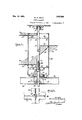
- Figure 1 is a view in elevation of a stack wi th my improved niotor located in the same.
- Figure 2 an enlarged detail vertical longitudinal section and part elevation of one of the motor units. i l
- Figure 3 is a detail horizontal section on the line 3-8 of Figure 2.
- the motor consists of a series of. open ended cylinders 29 each having a spiral vane 28 secured to the outer wall and a spiral vane secured by means of a flange do to the inner wall.v
- the vanes slightly from the shaft 47 while the outer edges of the vanes 28 are spaced slightly from the inner wall of the stack 15.
- the cylinders 29 and likewise the vanes 28 and 45 are connected to the shaft d7 by means of radially disposed rods 49 having their inner ends secured to sleeves 50 which are rigid with the shaft 47 while their outer ends are secured in any approved manner in bosses 51 formed upon the inner wall of the cylinders 29.
- the rods 49 are carried in spaced relation with each other along the inner wall of each cylinder 29, certain of the rods being located in planes which are at right angles to the planes passing through the other rods.
- the shafts 47, as are the cylinders 29, are formed in sections and are connected together at their adjacent aligned ends 52 and 53 by means of bolts 54.
- the end 52 is hollow as shown and is adapted to receive the reduced portion 55 of the upper end of a second aligned section of the shaft. This reduced end is provided with elongated slots 56 where the bolts 5% pass through the connected ends of the shafts so that'the ends of the shafts may be moved towards each other in case, of wear.
- each section 52 of the combined shaft passes through a bearin 57 andis secured at 58 to said bearin 751cc bearing is supported in a flanged race 59 and a plurality of rollers 60 and 61 are adapted to aid, in the elimination of friction between the parts.
- the race 59 is carried by the horizontal beams 36 and 37 so that each individual cylinder 29 together with its vanes 28 and 45 and section 47 of the shaft is supported entirely by the bearings and the race 59, and each of these bearings is carried at spaced points along the vertical stack 15 by means of a spider formed of eye beams 36 and 37.
- a hollow boss 62 through which a section 47 of a use is passed and adjacent the bearsing 57 p
- doors 3% are located adjacent the beams 36 and 37 in the stack and adjacent the bearings 57 so that when desired the bearings maybe inspected and repaired without any inconvenience.
- a-gear 63 from which power can be taken in any desi-red'way as for instance the manner shown in Figur 2 of my original application, but as such cific mechanism for taking off the power constitutes no part of the present application further disclosure thereof in this case is thought to be unnecessary.
- a circulation of air is maintained in the stack 15 fromthe hollow base to the upper extreme end.
- the air passing upwardly through the stack 15 impinges upon the spiral blades and causes a rapid rotation of the cylinders 29.
- the corrugated blades together. with the close association of these blades with the shaft 47 and the inner wall of thestack 15 will aid in maintaining a predetermined air pressure in the stack for the most efficient operation of the motors.
- Thetopmost section of the shaft-.47 is journalled in the bearing box 7 5 in which are located roller bearings 76 and a ball bearing 77, the ball bearing being mounted upon the reduced end 78 of the shaft.
- the bearing box is carried by a spider 79 secured to the top of the stack 15.
- a power generator ofthe kind wherein is provided a stack and means for delivering air to the bottom of said stack; an air motor inthe stack, said air motor com prising aplurality of sections in vertical alignment, each section consisting of a shaft, an open ended cylindrical member secured to andsp'aced from the shaftand also spaced from the inner wall of the. stack, a spiral vane secured to the outer wall of the cylindrical member, and a spiral vanesecured to the inner wall of said cylindrical member.
- a stack and means for delivering air to pass through said stack an air motor in the stack, said air motor comprising a plu rality of sections in vertical alignment, each section consisting of a shaft, an open ended cylinder secured to and spaced from the shaft and also spaced from the inner wall of the stack, asp' al vane secured to the outer wall of the cylindrical member and a spiral vane secured to the inner wall of said cy- ..in. is provided a stack and means for delivering air to the bottom of said stack;
- said air motor in the stack, said air motor com-- prising a plurality of sections in vertical alignment, each section consisting of a shaft, an open ended cylindrical member secured to and spaced from the shaft and also spaced from the inner wall of the stack, a spiral vane secured to the outer wall of the cylindrical member, and a spiral vane secured to the inner wall of said cylindrical member, said spiral vanes being corrugated transversely.
- a stack In a power plant, a stack, a motor mounted longitudinally of the stack and comprising a plurality of sections, each section consisting ofan open ended cylinder mounted concentrically in the stack, a shaft located centrally of the cylinder and provided with a plurality of spaced sleeves, bars connecting the sleeves with the inner walls of the cylinder, a spiral ⁇ ane secured to the outer wall of the cylinder and having its outer free edge terminating adjacent the inner wall of the stack, a vane secured to the inner wall of the cylinder and spirally aligned with-the external vane, spiders located in spaced relation in the stack and between the adjacent ends of the cylinders, a bearing carried by the spider and connected to the upper end. ofashaft in a cylinder, the lower end of the shaft in thecylinder being connected with theupper end in an ad jacent cylinder.
- a power plant a stack, a motor mounted longitudinally of the stack and comprising a plurality of sections, each, section consisting of an open ended cylinder mounted concentrically in the stack, a shaft located centrally of the cylinder and provided with a plurality of spaced sleeves, bars connecting the sleeves with the inner walls of the cylinder, a spiral vane secured to the outer wallof the cylinder andhaving its outer free edge terminating adjacent the inner/wall of the stack, a vane secured to the inn'er wall of.
Description
May 31, 1927.
1,631,069 w. M. SMITH rowan emmnmon Original Filed Sept. 4. 1925 2 Shuts-Sheet 1 INVENTOR William/)[Smiflu lpatented May 31, 1927.
niursn STATES ennie PATENT OFFICE.
POWER GENERATOR.
original application filed September 4, 1925, Serial No. 54,492. Divided and this application filed June 2, 1926. Serial No. 113,301. r v
This invention relates to certain new and useful improvements in power generators and the present invention particularly has for its object to provide certain improve ments in the motor used in such power generators. p 1
The present invention relates to that class of power generators in which is provided a stack and a motor located on a vertical axis within the stack operated by the passage of air through the stack, and the present application is a division of my application filed September l 1925, Serial No. %,492.
in its general nature the present invention resides in the provision of an improved motor consisting of a series of open ended cylinders located on a sectional shaft within the stack and having internal and external wines by which the cylinders are turned to impart their rotation to the'shaft;
in its more detailed nature the invention resides in those novel features of construc tion, combination and arrangement of parts, all of which will be first fully described, then a be specifically pointed out in the appended claims, reference being had to the accoin: ninyingsg drawings, in which:
Figure 1 is a view in elevation of a stack wi th my improved niotor located in the same. Figure 2 an enlarged detail vertical longitudinal section and part elevation of one of the motor units. i l
Figure 3 is a detail horizontal section on the line 3-8 of Figure 2.
In the drawings like numerals of reference indicatelike parts in all the figures and the same numerals of reference are employed for the same parts as are employed in' my original application aforesaid. This is done for convenience of cross referencin In the drawings and 31represent the steel supports for the stack 15 which is mounted on the hollow basev16, from which base the-air passes up through the stack 15. As the construction of the stack, the
base, and the means for accelerating the air passage through the stack constitutes'no part of this application further description thereof is thought to be unnecessary.
Referring more particularlyto Figure 2 it will be seen that the motor consists of a series of. open ended cylinders 29 each having a spiral vane 28 secured to the outer wall and a spiral vane secured by means of a flange do to the inner wall.v The vanes slightly from the shaft 47 while the outer edges of the vanes 28 are spaced slightly from the inner wall of the stack 15.
The cylinders 29 and likewise the vanes 28 and 45 are connected to the shaft d7 by means of radially disposed rods 49 having their inner ends secured to sleeves 50 which are rigid with the shaft 47 while their outer ends are secured in any approved manner in bosses 51 formed upon the inner wall of the cylinders 29. The rods 49 are carried in spaced relation with each other along the inner wall of each cylinder 29, certain of the rods being located in planes which are at right angles to the planes passing through the other rods. The shafts 47, as are the cylinders 29, are formed in sections and are connected together at their adjacent aligned ends 52 and 53 by means of bolts 54. The end 52 is hollow as shown and is adapted to receive the reduced portion 55 of the upper end of a second aligned section of the shaft. This reduced end is provided with elongated slots 56 where the bolts 5% pass through the connected ends of the shafts so that'the ends of the shafts may be moved towards each other in case, of wear.
, The upper end of each section 52 of the combined shaft passes through a bearin 57 andis secured at 58 to said bearin 751cc bearing is supported in a flanged race 59 and a plurality of rollers 60 and 61 are adapted to aid, in the elimination of friction between the parts. The race 59 is carried by the horizontal beams 36 and 37 so that each individual cylinder 29 together with its vanes 28 and 45 and section 47 of the shaft is supported entirely by the bearings and the race 59, and each of these bearings is carried at spaced points along the vertical stack 15 by means of a spider formed of eye beams 36 and 37. At the central portion of eachweb and where the beams 36 and 37 arevconnected together is provided a hollow boss 62 through which a section 47 of a use is passed and adjacent the bearsing 57 p As shown doors 3% are located adjacent the beams 36 and 37 in the stack and adjacent the bearings 57 so that when desired the bearings maybe inspected and repaired without any inconvenience.
At the extreme lower end of the shaft 15. which projects into the hollow base member 16 there is provided a-gear 63 from which power can be taken in any desi-red'way as for instance the manner shown in Figur 2 of my original application, but as such cific mechanism for taking off the power constitutes no part of the present application further disclosure thereof in this case is thought to be unnecessary.
The operation of my device is as follows:
A circulation of air is maintained in the stack 15 fromthe hollow base to the upper extreme end. The air passing upwardly through the stack 15 impinges upon the spiral blades and causes a rapid rotation of the cylinders 29. The corrugated blades together. with the close association of these blades with the shaft 47 and the inner wall of thestack 15 will aid in maintaining a predetermined air pressure in the stack for the most efficient operation of the motors.
Thetopmost section of the shaft-.47 is journalled in the bearing box 7 5 in which are located roller bearings 76 and a ball bearing 77, the ball bearing being mounted upon the reduced end 78 of the shaft. The bearing box is carried by a spider 79 secured to the top of the stack 15.
From the foregoing description, taken in connection with the accompanying drawings, it'is thought the complete construction, operation and advantages of my invention will beclear to those skilled in the art to which it relates.
\Vhat Iclaim is:
1. In a power generator ofthe kind wherein is provided a stack and means for delivering air to the bottom of said stack; an air motor inthe stack, said air motor com prising aplurality of sections in vertical alignment, each section consisting of a shaft, an open ended cylindrical member secured to andsp'aced from the shaftand also spaced from the inner wall of the. stack, a spiral vane secured to the outer wall of the cylindrical member, and a spiral vanesecured to the inner wall of said cylindrical member. V j
.2. Ina power plant of the kind wherein is provided a stack and means for delivering air to pass through said stack; an air motor in the stack, said air motor comprising a plu rality of sections in vertical alignment, each section consisting of a shaft, an open ended cylinder secured to and spaced from the shaft and also spaced from the inner wall of the stack, asp' al vane secured to the outer wall of the cylindrical member and a spiral vane secured to the inner wall of said cy- ..in. is provided a stack and means for delivering air to the bottom of said stack; an
air motor in the stack, said air motor com-- prising a plurality of sections in vertical alignment, each section consisting of a shaft, an open ended cylindrical member secured to and spaced from the shaft and also spaced from the inner wall of the stack, a spiral vane secured to the outer wall of the cylindrical member, and a spiral vane secured to the inner wall of said cylindrical member, said spiral vanes being corrugated transversely.
In a power plant, a stack, a motor mounted longitudinally of the stack and comprising a plurality of sections, each section consisting ofan open ended cylinder mounted concentrically in the stack, a shaft located centrally of the cylinder and provided with a plurality of spaced sleeves, bars connecting the sleeves with the inner walls of the cylinder, a spiral \ane secured to the outer wall of the cylinder and having its outer free edge terminating adjacent the inner wall of the stack, a vane secured to the inner wall of the cylinder and spirally aligned with-the external vane, spiders located in spaced relation in the stack and between the adjacent ends of the cylinders, a bearing carried by the spider and connected to the upper end. ofashaft in a cylinder, the lower end of the shaft in thecylinder being connected with theupper end in an ad jacent cylinder.
5. In a; power plant, a stack, a motor mounted longitudinally of the stack and comprising a plurality of sections, each, section consisting of an open ended cylinder mounted concentrically in the stack, a shaft located centrally of the cylinder and provided with a plurality of spaced sleeves, bars connecting the sleeves with the inner walls of the cylinder, a spiral vane secured to the outer wallof the cylinder andhaving its outer free edge terminating adjacent the inner/wall of the stack, a vane secured to the inn'er wall of. the cylinderand spirally aligned with the external vane, spiders loe cated in spaced relation in the stack'and between the adjacent ends of the cylinders, a bearing carried by the spider and connected to the upper endof ashaft in, acylinder, the lower end of the shaft in the cylinderbeing connected with the upper end in an adj acent cylinder, said connections between the'ends of the shaft permitting play whereby slaclris taken up in the shaft because of wear.
WILLLiA l M; snrrn ion llt)
Priority Applications (1)
| Application Number | Priority Date | Filing Date | Title |
|---|---|---|---|
| US113301A US1631069A (en) | 1925-09-04 | 1926-06-02 | Power generator |
Applications Claiming Priority (2)
| Application Number | Priority Date | Filing Date | Title |
|---|---|---|---|
| US5449225A | 1925-09-04 | 1925-09-04 | |
| US113301A US1631069A (en) | 1925-09-04 | 1926-06-02 | Power generator |
Publications (1)
| Publication Number | Publication Date |
|---|---|
| US1631069A true US1631069A (en) | 1927-05-31 |
Family
ID=26733091
Family Applications (1)
| Application Number | Title | Priority Date | Filing Date |
|---|---|---|---|
| US113301A Expired - Lifetime US1631069A (en) | 1925-09-04 | 1926-06-02 | Power generator |
Country Status (1)
| Country | Link |
|---|---|
| US (1) | US1631069A (en) |
Cited By (8)
| Publication number | Priority date | Publication date | Assignee | Title |
|---|---|---|---|---|
| US20070041823A1 (en) * | 2005-08-22 | 2007-02-22 | Miller Donald C | Fluid energy converter |
| US20100001529A1 (en) * | 2008-07-02 | 2010-01-07 | Rosefsky Jonathan B | Ribbon drive power generation and method of use |
| US20100267510A1 (en) * | 2009-04-16 | 2010-10-21 | Fallbrook Technologies Inc. | Continuously variable transmission |
| US7883442B2 (en) | 2001-04-26 | 2011-02-08 | Fallbrook Technologies Inc. | Continuously variable transmission |
| US8321097B2 (en) | 2007-12-21 | 2012-11-27 | Fallbrook Intellectual Property Company Llc | Automatic transmissions and methods therefor |
| US8398518B2 (en) | 2008-06-23 | 2013-03-19 | Fallbrook Intellectual Property Company Llc | Continuously variable transmission |
| US8776633B2 (en) | 2006-01-30 | 2014-07-15 | Fallbrook Intellectual Property Company Llc | System for manipulating a continuously variable transmission |
| US9677650B2 (en) | 2013-04-19 | 2017-06-13 | Fallbrook Intellectual Property Company Llc | Continuously variable transmission |
-
1926
- 1926-06-02 US US113301A patent/US1631069A/en not_active Expired - Lifetime
Cited By (28)
| Publication number | Priority date | Publication date | Assignee | Title |
|---|---|---|---|---|
| US7883442B2 (en) | 2001-04-26 | 2011-02-08 | Fallbrook Technologies Inc. | Continuously variable transmission |
| WO2007044128A2 (en) * | 2005-08-22 | 2007-04-19 | Viryd Technologies Inc. | Fluid energy converter |
| WO2007044128A3 (en) * | 2005-08-22 | 2007-07-19 | Fallbrook Technologies Inc | Fluid energy converter |
| US7600963B2 (en) | 2005-08-22 | 2009-10-13 | Viryd Technologies Inc. | Fluid energy converter |
| US20100034656A1 (en) * | 2005-08-22 | 2010-02-11 | Viryd Technologies Inc. | Fluid energy converter |
| US20070041823A1 (en) * | 2005-08-22 | 2007-02-22 | Miller Donald C | Fluid energy converter |
| US8776633B2 (en) | 2006-01-30 | 2014-07-15 | Fallbrook Intellectual Property Company Llc | System for manipulating a continuously variable transmission |
| US8626409B2 (en) | 2007-12-21 | 2014-01-07 | Fallbrook Intellectual Property Company Llc | Automatic transmissions and methods therefor |
| US10704687B2 (en) | 2007-12-21 | 2020-07-07 | Fallbrook Intellectual Property Company Llc | Automatic transmissions and methods therefor |
| US9739375B2 (en) | 2007-12-21 | 2017-08-22 | Fallbrook Intellectual Property Company Llc | Automatic transmissions and methods therefor |
| US9249880B2 (en) | 2007-12-21 | 2016-02-02 | Fallbrook Intellectual Property Company Llc | Automatic transmissions and methods therefor |
| US8321097B2 (en) | 2007-12-21 | 2012-11-27 | Fallbrook Intellectual Property Company Llc | Automatic transmissions and methods therefor |
| US8641572B2 (en) | 2008-06-23 | 2014-02-04 | Fallbrook Intellectual Property Company Llc | Continuously variable transmission |
| US9528561B2 (en) | 2008-06-23 | 2016-12-27 | Fallbrook Intellectual Property Company Llc | Continuously variable transmission |
| US10066713B2 (en) | 2008-06-23 | 2018-09-04 | Fallbrook Intellectual Property Company Llc | Continuously variable transmission |
| US9074674B2 (en) | 2008-06-23 | 2015-07-07 | Fallbrook Intellectual Property Company Llc | Continuously variable transmission |
| US8398518B2 (en) | 2008-06-23 | 2013-03-19 | Fallbrook Intellectual Property Company Llc | Continuously variable transmission |
| US20100001529A1 (en) * | 2008-07-02 | 2010-01-07 | Rosefsky Jonathan B | Ribbon drive power generation and method of use |
| US8350400B2 (en) | 2008-07-02 | 2013-01-08 | Hydrocoil Power, Inc. | Ribbon drive power generation and method of use |
| US8148839B2 (en) * | 2008-07-02 | 2012-04-03 | Rosefsky Jonathan B | Ribbon drive power generation and method of use |
| US9279482B2 (en) | 2009-04-16 | 2016-03-08 | Fallbrook Intellectual Property Company Llc | Continuously variable transmission |
| US20100267510A1 (en) * | 2009-04-16 | 2010-10-21 | Fallbrook Technologies Inc. | Continuously variable transmission |
| US9920823B2 (en) | 2009-04-16 | 2018-03-20 | Fallbrook Intellectual Property Company Llc | Continuously variable transmission |
| US8663050B2 (en) | 2009-04-16 | 2014-03-04 | Fallbrook Intellectual Property Company Llc | Continuously variable transmission |
| US8360917B2 (en) | 2009-04-16 | 2013-01-29 | Fallbrook Intellectual Property Company Llc | Continuously variable transmission |
| US10746270B2 (en) | 2009-04-16 | 2020-08-18 | Fallbrook Intellectual Property Company Llc | Continuously variable transmission |
| US9677650B2 (en) | 2013-04-19 | 2017-06-13 | Fallbrook Intellectual Property Company Llc | Continuously variable transmission |
| US10323732B2 (en) | 2013-04-19 | 2019-06-18 | Fallbrook Intellectual Property Company Llc | Continuously variable transmission |
Similar Documents
| Publication | Publication Date | Title |
|---|---|---|
| US1631069A (en) | Power generator | |
| US1697574A (en) | Rotor adapted to be driven by wind or flowing water | |
| US2371821A (en) | Air blower | |
| KR890001322B1 (en) | Rotary means for use as a heat source | |
| DE50112352D1 (en) | homogenizing | |
| US20120098270A1 (en) | External Rotor Generator of Vertical Axis Wind Turbine | |
| RU2534583C2 (en) | Mill with torque transfer | |
| CN106091638A (en) | A kind of spiral cylinder drying device | |
| US1902439A (en) | Flying worm steam motor | |
| CN106533008A (en) | Rotor, motor and compressor | |
| NO20121215A1 (en) | Vessel propulsion system | |
| US3148627A (en) | Reciprocating pump | |
| CH363119A (en) | Centrifugal fan | |
| KR20110058110A (en) | Vertical axis wind power generator | |
| US2423634A (en) | Compressor | |
| US921744A (en) | Ventilating-fan for mines. | |
| US1891306A (en) | Worm water motor | |
| US2787715A (en) | Coupling for vertical hydroelectric generator | |
| US1661360A (en) | Pump | |
| CN208417019U (en) | A kind of high speed two stage centrifugal air blower based on air hydrodynamic bearing | |
| CN105065334A (en) | Air collector allowing air volume to be adjustable | |
| US1576373A (en) | Power generator | |
| US1740596A (en) | Stream motor | |
| GB296682A (en) | Improvements in and relating to ball mills | |
| CN102852711B (en) | Laminar rotating-wing wind turbine |