EP3034306A1 - Assembly for pretreatment of an object intended for being printed with at least one ink - Google Patents
Assembly for pretreatment of an object intended for being printed with at least one ink Download PDFInfo
- Publication number
- EP3034306A1 EP3034306A1 EP15180794.8A EP15180794A EP3034306A1 EP 3034306 A1 EP3034306 A1 EP 3034306A1 EP 15180794 A EP15180794 A EP 15180794A EP 3034306 A1 EP3034306 A1 EP 3034306A1
- Authority
- EP
- European Patent Office
- Prior art keywords
- wiping
- station
- assembly
- pretreatment
- frame
- Prior art date
- Legal status (The legal status is an assumption and is not a legal conclusion. Google has not performed a legal analysis and makes no representation as to the accuracy of the status listed.)
- Withdrawn
Links
Images


Classifications
-
- B—PERFORMING OPERATIONS; TRANSPORTING
- B41—PRINTING; LINING MACHINES; TYPEWRITERS; STAMPS
- B41J—TYPEWRITERS; SELECTIVE PRINTING MECHANISMS, i.e. MECHANISMS PRINTING OTHERWISE THAN FROM A FORME; CORRECTION OF TYPOGRAPHICAL ERRORS
- B41J11/00—Devices or arrangements of selective printing mechanisms, e.g. ink-jet printers or thermal printers, for supporting or handling copy material in sheet or web form
- B41J11/0015—Devices or arrangements of selective printing mechanisms, e.g. ink-jet printers or thermal printers, for supporting or handling copy material in sheet or web form for treating before, during or after printing or for uniform coating or laminating the copy material before or after printing
-
- B—PERFORMING OPERATIONS; TRANSPORTING
- B05—SPRAYING OR ATOMISING IN GENERAL; APPLYING FLUENT MATERIALS TO SURFACES, IN GENERAL
- B05C—APPARATUS FOR APPLYING FLUENT MATERIALS TO SURFACES, IN GENERAL
- B05C11/00—Component parts, details or accessories not specifically provided for in groups B05C1/00 - B05C9/00
- B05C11/02—Apparatus for spreading or distributing liquids or other fluent materials already applied to a surface ; Controlling means therefor; Control of the thickness of a coating by spreading or distributing liquids or other fluent materials already applied to the coated surface
-
- B—PERFORMING OPERATIONS; TRANSPORTING
- B41—PRINTING; LINING MACHINES; TYPEWRITERS; STAMPS
- B41J—TYPEWRITERS; SELECTIVE PRINTING MECHANISMS, i.e. MECHANISMS PRINTING OTHERWISE THAN FROM A FORME; CORRECTION OF TYPOGRAPHICAL ERRORS
- B41J3/00—Typewriters or selective printing or marking mechanisms characterised by the purpose for which they are constructed
- B41J3/407—Typewriters or selective printing or marking mechanisms characterised by the purpose for which they are constructed for marking on special material
- B41J3/4073—Printing on three-dimensional objects not being in sheet or web form, e.g. spherical or cubic objects
Definitions
- the invention also relates to a printing machine incorporating such a pretreatment assembly, and a method corresponding to the pretreatment assembly.
- inkjet printing or any other method of direct printing on an object, it is known to treat the surface of the object to be printed before printing to improve the adhesion of the ink to the object. 'object.
- a glass object printed with organic inks dried by UV rays it is known that the resistance of the ink is improved by coating the surface of the glass before printing, by for example, a liquid containing silane. Such a liquid is called adhesion promoter.
- the pretreatment station comprises an applicator adjustable in position and incorporating a pad of felt soaked with the chemical and applied against the portion of the surface of the object to be pretreated.
- the applicator also includes a dropper for imbibing the buffer at a suitable rate.
- Such a pretreatment station gives overall satisfaction. Occasionally, however, imperfections in printing have been found due to defects in the distribution of the ink on the object.
- An object of the invention is therefore to provide an improved pretreatment, which is both a promoter of the adhesion of the subsequently deposited ink and which allows an impression of improved quality.
- the subject of the invention is a pretreatment assembly of the type described above, comprising a wiping station adapted to wipe the coated surface to obtain a wiped surface at least in part, the object being in a position wiper in which the object is located vis-à-vis the wiping station.
- the printing machine 1 adapted to print an object 5 of revolution about an axis ⁇ .
- print is meant to deposit at least one ink on the object.
- the printing machine 1 is advantageously suitable for serially printing a plurality of object-like objects provided by a first conveying system (not shown). The printing machine 1 is then clean to deposit the objects after printing on a second conveyor system (not shown).
- the object 5 is for example a glass bottle.
- the object 5 has a surface 7 to be printed which is convex ( figure 2 and 4 ) in the example shown.
- the object 5 is cylindrical, or has a concave surface 7.
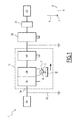
- the printing machine 1 successively comprises a station 10 for supplying the object 5, a set 15 for pretreatment of the object, a station 20 for printing the object, an optional station 22 for final polymerization of the object. the ink, and a removal station 25 of the object.
- the printing machine 1 also comprises a frame 30 on which the stations 10, 20, 22, 25 and the assembly 15 are advantageously fixed.
- stations 10, 20, 22 and 25 are known in themselves, for example from the aforementioned patent application made by the applicant, and will not be described in detail.
- the station 10 is for example adapted to enter the object 5 to be printed on the first conveyor system and deposit the object on a system object 32 of the preprocessing assembly 15.
- the station 20 is a printing station comprising for example one or more inkjet printheads, advantageously at least four to achieve four-color printing.
- the station 25 is for example suitable for taking the object 5 on the object-holder system 32 and placing the object on the second conveying system.
- the printing machine 1 comprises several object-bearing systems so as to process several objects at a time.
- one of the objects is presented to any processing station of the printing machine 1 by one of the object-bearing systems, while another of the objects is presented to another processing station of any kind. of the printing machine by another of the object-bearing systems.
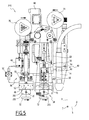
- the assembly 15 comprises, in addition to the aforementioned object-holder system 32, a frame 34 integral with the frame 30 of the printing machine 1, and a pre-treatment station 36 and a wiping station 38 fixed to the frame 34
- the assembly 15 also comprises a secondary treatment station 40, for example by plasma, fixed on the frame 34.
- the frame 34 is not mechanically secured to the frame 30, but rests directly on the ground.
- the object-holder system 32 is for example adapted, as described below, to present the object 5 successively to the assembly 15, then to the stations 20, 22.
- the object-bearing system 32 is adapted to successively move the object 5 relative to the frame 34 to a pre-treatment position ( Figures 2 to 4 ), in which the object is vis-à-vis the pretreatment station 36, at a wiping position (not shown), in which the object is vis-à-vis the wiping station 38 , then to a position of secondary pretreatment (not shown), in which the object is vis-à-vis the secondary pretreatment station 40.
- the object-holder system 32 is for example of the base-point type.
- the object-holder system 32 is able to carry the object 5, in the example by wedging it between the base and the tip, and advantageously to rotate the object respectively relative to the stations 36, 38, 40, 20, 22 around of the axis of revolution ⁇ .
- the preprocessing station 36 ( Figures 2 to 4 ) comprises a frame 42, an applicator 44 mounted on the frame and comprising for example a felt pad 46 adapted to be impregnated with an ink adhesion promoter, and a reservoir 48 of the liquid.
- the frame 42 is mounted on the frame 34 in a manner to be described below.
- the tank 48 is for example fluidically connected by gravity to a solenoid valve 50 advantageously adjustable by an operator to ensure a drop-by-drop distribution of the liquid at the felt pad 46.
- the buffer 46 is for example clamped in a metal piece 52 adjustable relative to the frame 42 in translation in a pressing direction V, for example vertical, with a button 54, so that the felt pad 46 is in contact with the surface 7 of the object 5 in the pretreatment position.
- the adhesion promoter advantageously comprises silane, in a proportion for example between 0.15% and 3% by weight, as described for example in the document US 2002/061939 , and at least one solvent.
- the solvent is chosen to allow rapid drying of the surface 7 coated by the pretreatment station 36.
- the solvent is for example alcohol.
- the adhesion promoter is for example liquid at room temperature, especially at 20 ° C.
- the adhesion promoter is solid or pasty.
- the metal part 52 and the felt pad 46 are elongate in a transverse direction T substantially perpendicular to the pressing direction V.
- the felt pad 46 has an extension E1 ( figure 4 ) in the transverse direction T.
- the extension E1 is advantageously greater than or equal to the extension of the surface 7 along the axis of revolution ⁇ of the object 5.
- the metal part 52 is advantageously pivotally mounted relative to the frame 42 about a pivot axis D1 ( figure 4 ) and locked by adjusting screws 55.
- the transverse direction T is advantageously substantially parallel to the axis of revolution ⁇ of the object 5.
- the felt pad 46 is adjustable relative to the object 5 in the pretreatment position in height in the pressing direction V and in parallel with the surface 7 about the pivot axis D1.
- a tilt adjustment is also provided.
- the wiping station 38 ( figures 2 and 3 ) comprises a frame 56 mounted to move relative to the frame 34 of the assembly 15 in translation in the transverse direction T, and a carriage 58 movable in translation in the pressing direction V relative to the frame.
- the wiping station 38 also comprises a jack 59 fixed to the carriage 58, a wiper strip 60 adapted to wipe the surface 7, a band support 62 actuated by the jack 59 with respect to the carriage 58 in the pressing direction V, and a scrolling system 64 capable of scrolling the wiper strip 60 on the tape support in a scrolling direction D.
- the wiping station 38 further comprises a drive system 66 ( figure 4 ) of the frame 56 transversely relative to the frame 34, and an actuating system 68 ( figure 3 ) of the carriage 58 with respect to the frame 56.
- the frame 56 of the wiping station 38 and the frame 42 of the pretreatment station 36 are for example mechanically fixed and advantageously form a single frame.
- the frame 56 extends for example substantially in a plane P perpendicular to the transverse direction T.
- the wiper strip 60 is made of a material adapted to leave the portion of the surface 7 coated free of any debris from the material of the wiper strip.
- the wiper strip 60 is for example made of an absorbent material, lint-free and not rough.
- the material is for example a fabric.
- the material is nonwoven.
- the wiper strip 60 advantageously has a flat width, in the unstretched state, of between 10 mm and 50 mm.
- the wiper strip 60 advantageously has a first elasticity in a longitudinal direction and a second elasticity in a transverse direction, the second elasticity being greater than the first elasticity by a factor of 10.
- the tape support 62 comprises for example a metal support 69 fixed on the jack 59, and a flexible tip 70, advantageously profiled.
- the flexible tip 70 is for example elastomeric material, preferably flexible silicone.
- the flexible tip 70 has a hardness of between 5 and 50 Shore A.
- the flexible tip 70 is elongate in a support direction S ( figures 2 , 3 , 4 and 8 ) and advantageously has a section "V" in section along a plane perpendicular to the support direction.
- the "V” has a point directed towards the object 5 in the wiping position.
- the "V” has an angle of aperture a ( figure 8 ) between 30 and 150 degrees around the support direction S, preferably between 90 and 120 degrees.
- the "V" of the flexible tip 70 defines a bisector B ( figure 8 ) substantially parallel to the pressing direction V.
- the flexible tip 70 changes shape in contact with the surface 7.
- the flexible tip 70 then has a rounded section, as visible on the figure 9 .
- the shape of the flexible tip 70 is adapted to oppose a sliding of the wiper strip 60 on the tape carrier 62 perpendicular to the direction of travel D when the wiper strip is stretched on the flexible tip.
- the drive system 68 of the carriage 58 comprises, for example, a jack 72.
- the jack 59 is adapted to press the flexible tip 70 against the surface 7 of the object 5 when the object 5 is in the wiping position.
- one and / or the other of the cylinders 59 and 72 are replaced by other types of actuators known in themselves.
- the scrolling system 64 is adapted to scroll the wiper strip 60 on the flexible tip 70 in a running direction D so as to renew the portion of the wiper strip 60 in contact with the surface 7 coated.
- the scrolling system 64 comprises a feed reel 74 and a rewinding reel 76.
- the scrolling system 64 comprises, successively in the direction of movement of the wiper strip 60, pulleys 78, 80, 82, 84, and an arm 86 having a roller 88 capable of pressing the wiper strip 60 against the pulley 82.
- the scrolling system 64 also comprises a motor 90 ( figure 7 ), a driving pulley 92 driven in rotation by the motor and connected by a belt to a return pulley 94, itself secured to the pulley 82.
- the scrolling system 64 also includes a guide 96 ( figure 3 ) forming a fork on either side of the flexible tip 70 in the direction of travel D.
- the return pulley 94 is connected by a belt to the rewinding reel 76.
- the guide 96 is for example integral with the carriage 58.
- Each end of the fork comprises respectively a surface 98, 100 for supporting and guiding the wiper strip 60 on either side of the flexible tip 70 in the direction of travel D.
- the wiper strip 60 for example follows a path of trapezoidal shape seen in the transverse direction T (FIG. figure 3 ).
- the feed reel 74, the rewind reel 76, the pulleys 78, 80, 82, 84, the roller 88, the drive pulley 92 and the idler pulley 94 are rotatably mounted relative to the frame 56 about axes. for example substantially parallel to the transverse direction T.
- the drive pulley 92 and the return pulley 94 are located transversely on the other side of the frame 56 relative to the pulleys 78, 80, 82, 84.
- the scrolling direction D is for example substantially coincident with the direction of support S.
- the running direction D is perpendicular to the pressing direction V and forms an angle with the support direction S, preferably 90 degrees around the pressing direction V.
- the drive system 66 comprises a rack 102 slidably mounted transversely relative to the frame 34, and two plates 104, 106 intended to allow adjustment of the parallelism of the strip support 62 with the surface 7.
- the drive system 66 comprises a servomotor 108 fixed on the frame 34 and having a pinion 110 meshing on the rack 102.
- the two plates 104, 106 extend substantially parallel to each other in a plane perpendicular to the transverse direction T.
- the two plates 104, 106 are connected to each other by straightening screws 112.
- the plate 104 is fixed on the rack 102.
- the plate 106 is fixed on the frame 56 of the wiping station 38.
- the secondary pretreatment station 40 comprises a plasma torch 114, for example oriented substantially in the pressing direction V.
- the secondary pre-treatment station 40 also has a common frame with the chassis 56 of the wiping station 38.
- the plasma torch 114 has an end 116 in the pressing direction V, the end 116 being advantageously situated substantially at the same level in the pressing direction as the flexible tip 70 and the felt pad 46.
- the station 10 brings the object 5 of the first conveying system (not shown) to the object-holder system 32.
- the object-bearing system 32 carries the object 5 and presents it to the pre-treatment station 36 in the pretreatment position ( Figures 2 to 4 ) to subject the object to a preprocessing step.
- the felt pad 46 touches the surface 7 to be pretreated.
- the inclination of the felt pad 46 with respect to the object 5 around the pivot axis D1 has been adjusted by an operator (not shown).
- the felt pad 46 is inclined to conform to the surface 7.
- the free edge of the felt pad 46 is placed substantially parallel to the axis of revolution ⁇ .
- the position of the felt pad 46 with respect to the frame 42 in the pressing direction V is set by the operator with the button 54.
- the adhesion promoter liquid contained in the tank 48 flows into the felt pad 46 drop by drop.
- the liquid flow rate is adjusted by the solenoid valve 50 so that the felt pad 46 is properly soaked.
- the object-holder system 32 rotates the object 5 with respect to the felt pad 46 around the axis of revolution ⁇ so that the felt pad sweeps the surface 7, advantageously all around the periphery of the surface around it. of the axis of revolution ⁇ . A coated surface 7 is thus obtained at the end of the pretreatment stage.
- the object-carrier system 32 is translated for example in the support direction S to the wiping station 38 to place the object 5 in the wiping position to subject the object to a wiping step.
- the wiping position is therefore deduced by such a translation of the pretreatment position represented on the figure 3 .
- the tape carrier 62 of the wiper station 38 is lowered by the cylinder 59.
- the flexible tip 70 of the tape carrier 62 presses the wiper strip 60 onto the coated surface 7.
- the flexible tip 70 moves from the shape shown on the figure 8 to the rounded shape shown on the figure 9 .
- the object-holder system 32 rotates the object 5 again, this time with respect to the flexible tip 70 about the axis of revolution ⁇ so that the wiper strip 60 scans a portion of the surface 7 coated.
- the drive system 66 of the wiper station 38 moves the frame 56, thus the flexible tip 70 and the wiper strip 60, transversely relative to the object 5, advantageously continuously.
- the portion swept by the wiper strip 60 preferably has a helical shape covering the entire surface 7 coated.
- the drive system 66 moves the frame 56 transversely incrementally each time the object 5 has made a turn around the axis of revolution ⁇ with respect to the flexible tip 70.
- the swept surface 7 is composed of successive rings transversely and which overlap.
- the scrolling system 64 of the wiping station 38 makes the wiper strip 60 move in contact with the flexible tip 70 and with respect to the flexible tip in the direction of travel D, preferably continuously.
- the part of the wiper strip 60 in contact with the surface 7 coated is constantly being renewed.
- the wiper strip 60 travels with respect to the flexible tip 70 over a distance of between 1/6 e and once the diameter of the object 5.
- a surface 7 wiped in part is obtained.
- in part it is meant that wiping equalizes the layer of liquid on the surface 7, without completely removing this layer.
- the tape support 62 is raised relative to the object 5 by the jack 59.
- the object-carrier system 32 for example translates in the support direction S to the secondary preprocessing station 40 to place the object 5 in the secondary pretreatment position to subject the object to a secondary preprocessing step.
- the position of secondary pretreatment is therefore deduced by such a translation of the wiping position on the figure 3 .
- secondary treatment is optional.
- the object-holder system 32 rotates the object 5 again about the axis of revolution ⁇ , this time with respect to the end 116 of the plasma torch 114 of the secondary pre-treatment station 40.
- the drive system 66 of the wiper station 38 moves the plasma torch 114 transversely relative to the object 5, advantageously continuously.
- the plasma scans the surface 7 by describing a helix.
- the wiped surface 7 is therefore plasma treated at the end of the secondary pretreatment step.
- the object-holder system 32 moves the object 5 to the printing station 20 where the object 5 undergoes a printing step, for example example in four-color process, then to the station 22 of final polymerization to undergo a final step of polymerization of the ink.
- the station 25 removes the object 5 from the object-holder system 32 and places the object for example on the second conveying system (not shown).
- the wiping of the coated surface 7 makes it possible to equalize the thickness of the adhesion promoting liquid layer.
- the surface tension forces are more uniform on the surface 7 during the printing step, which reduces or eliminates printing defects.
- the pretreatment unit remains a promoter of adhesion of the ink deposited during printing, since the liquid layer deposited by the pretreatment station 36 is not completely removed, the wiping by the wiping station 38 being partial.
- the pretreatment assembly 15 is therefore improved over existing assemblies.
- the fact that the wiper strip 60 is set in motion by the scrolling system 64 allows an adjustable renewal of the portion of the wiper strip in contact with the surface 7 coated.
- the flexible tip 70 in the shape of a "V” makes it possible to guide the wiper strip 60 and prevent the latter from sliding on the strip support 62 perpendicular to the direction of travel D during the wiping step.
- the plates 104, 106 allow a fine adjustment of the orientation, in particular that of the wiping station 38 with respect to the object 5.
- a pretreatment assembly 215 is described constituting a first variant of the assembly 15 represented on the Figures 1 to 4 .
- the assembly 215 is adapted to an object 205 having a surface 207 substantially flat, or a large radius of curvature, for example greater than 100 mm.
- the object 205 has for example a rectangular section.
- the object 205 has an axis ⁇ 'which is for example an axis of symmetry.
- the assembly 215 is structurally almost identical to the assembly 15.
- the similar elements bear the same numerical references and will not be described again. Only the differences, which relate to geometric and operating characteristics, will be described in detail below.
- the metal part 52 and the felt pad 46 are not elongate in the transverse direction T, but in the support direction S. With respect to the pre-treatment station of the assembly 15, the metal part 52 and the felt pad 46 are rotated 90 ° around the pressing direction V.
- the object-holder system 32 does not rotate the object 205 relative to the pretreatment station 36.
- the drive system 66 moves the frame 56, thus the frame 42, thus the felt pad 46, in translation relative to the object 5 in the transverse direction T, advantageously in a continuous manner.
- the felt pad 46 scans the surface 207 and coats it with a layer of liquid.
- the object-holder system 32 does not rotate the object 205 relative to the wiping station 38.
- the drive system 66 still moves the frame 56, so the flexible tip 70 and the wiper strip 60, transversely relative to the object 5, while the scrolling system 64 scrolls the wiper strip 60 relative to the flexible tip 70.
- the object-holder 32 does not rotate the object 205.
- the optional feature in which the running direction D and the support direction S are substantially merged makes it possible to process the entire surface 207 of the object 205, even if this surface has an extension in the larger support direction S the width of the wiper strip 60.
- the second variant differs from the set 15 represented on the Figures 1 to 5 in that the pretreatment station 36 and the wiping station form a single treatment and wiping station 36-38 (not shown, but easily deduced from the positions 36 and 38 of the assembly 15).
- the holder 32 does not move the object 5 of a pretreatment station to a separate wiper station, relative to the frame 34, but is adapted to hold the object 5 in the wiping position, in which the object is vis-à-vis the treatment and wiping station 36-38, that is to say vis-à-vis both the pre-treatment station and the wiping station.
- the treatment and wiping station 36-38 advantageously does not comprise a felt pad 46.
- the reservoir 18 is advantageously adapted to soak the wiper strip 60.
- the treatment and wiping station 36-38 can thus be seen as the wiping station 38 of the assembly 15, in which elements of the pretreatment station 36 would have been added, in particular those which allow the felt 46 to be imbibed.
- the operation of the second variant is substantially the same as that of the assembly 15, except that the object holder 32 directly places the object 5 in the wiping position before the preprocessing step.
- the wiper strip 60 is imbibed with the adhesion promoter.
- the object holder 32 rotates the object 5 relative to the wiper strip 60 so that the wiper strip sweeps the surface 7, preferably all around the surface.
- the scrolling system 64 scrolls the wiper strip 60 so as to renew the portion of the wiper strip in contact with the surface 7 of the object 5. It is then a dry, non-soaked part of the wiper strip. wiper strip 60 which is in contact with the surface 7.
- the wiping is then carried out in a similar manner to that of the assembly 15.
- the advantage of the second variant is, on the one hand, to save a station, since the pretreatment station is confused with the wiping station to form a mixed station, and secondly, to save a displacement of the object between two posts.
- the wiper strip 60 is advantageously applied to the object 5 so as to partially wind on the latter. Also, the tension of the wiper strip 60 is reflected in a sufficient pressure on the surface 7.
- an additional pressure force is possibly applied by the flexible tip 70 on the wiper strip 60.
- the third variant shows the merging characteristics of the pretreatment station 36 and the wiper station 38 described above for the second variant, but applied to the assembly 215.
- the object 205 is put in the wiping position even before the pretreatment.
- it is the wiper strip 60 which is impregnated with the adhesion promoter.
- the drive system 66 makes it possible to coat the surface 207 of the object 205.
- the scrolling system 64 scrolls the wiper strip 60 so as to renew the portion of the wiper strip in contact with the surface 207 of the object 2055.
- the wiping is then performed in a similar manner to that of the assembly 215.
Abstract
Ensemble (15) de prétraitement d'au moins un objet (5) destiné à être imprimé par au moins une encre, l'ensemble comportant : - un bâti (34), et - au moins un poste de prétraitement (36) adapté pour appliquer sur une surface (7) de l'objet au moins un promoteur d'adhérence de l'encre, et pour obtenir une surface (7) enduite. L'ensemble comprend un poste d'essuyage (38) adapté pour essuyer la surface (7) enduite pour obtenir une surface essuyée au moins en partie, l'objet étant dans une position d'e ssuyage dans laquelle il se situe en vis-à-vis du poste d'essuyage.Set (15) for pretreatment of at least one object (5) intended to be printed by at least one ink, the assembly comprising: - a frame (34), and - At least one pretreatment station (36) adapted to apply to a surface (7) of the object at least one adhesion promoter of the ink, and to obtain a surface (7) coated. The assembly comprises a wiping station (38) adapted to wipe the surface (7) coated to obtain a wiped surface at least in part, the object being in a ssuyage position in which it is located vis-à-vis to the wiping station.
Description
La présente invention concerne un ensemble de prétraitement d'au moins un objet destiné à être imprimé par au moins une encre, l'ensemble comportant :
- un bâti, et
- au moins un poste de prétraitement adapté pour appliquer sur une surface de l'objet au moins un promoteur d'adhérence de l'encre, et pour obtenir une surface enduite.
- a frame, and
- at least one pretreatment station adapted to apply on one surface of the object at least one adhesion promoter of the ink, and to obtain a coated surface.
L'invention concerne aussi une machine d'impression intégrant un tel ensemble de prétraitement, ainsi qu'un procédé correspondant à l'ensemble de prétraitement.The invention also relates to a printing machine incorporating such a pretreatment assembly, and a method corresponding to the pretreatment assembly.
Dans l'impression à jet d'encre ou dans tout autre procédé d'impression directe sur un objet, il est connu de traiter la surface de l'objet à imprimer avant l'impression pour améliorer l'adhérence de l'encre sur l'objet. Dans le cas d'un objet en verre imprimé à l'aide d'encres organiques séchées par des rayons UV, il est connu que l'on améliore la tenue de l'encre en enduisant la surface du verre avant l'impression, par exemple, d'un liquide contenant du silane. Un tel liquide est qualifié de promoteur d'adhérence.In inkjet printing or any other method of direct printing on an object, it is known to treat the surface of the object to be printed before printing to improve the adhesion of the ink to the object. 'object. In the case of a glass object printed with organic inks dried by UV rays, it is known that the resistance of the ink is improved by coating the surface of the glass before printing, by for example, a liquid containing silane. Such a liquid is called adhesion promoter.
Ainsi, le document
Dans le document déposé par la demanderesse sous le numéro
Un tel poste de prétraitement donne globalement satisfaction. Il a toutefois été constaté parfois des imperfections de l'impression imputables à des défauts dans la répartition de l'encre sur l'objet.Such a pretreatment station gives overall satisfaction. Occasionally, however, imperfections in printing have been found due to defects in the distribution of the ink on the object.
Un but de l'invention est donc de proposer un prétraitement amélioré, qui soit à la fois promoteur de l'adhérence de l'encre déposée ultérieurement et qui permette une impression d'une qualité améliorée.An object of the invention is therefore to provide an improved pretreatment, which is both a promoter of the adhesion of the subsequently deposited ink and which allows an impression of improved quality.
A cet effet, l'invention a pour objet un ensemble de prétraitement du type décrit ci-dessus, comprenant un poste d'essuyage adapté pour essuyer la surface enduite pour obtenir une surface essuyée au moins en partie, l'objet étant dans une position d'essuyage dans laquelle l'objet se situe en vis-à-vis du poste d'essuyage.For this purpose, the subject of the invention is a pretreatment assembly of the type described above, comprising a wiping station adapted to wipe the coated surface to obtain a wiped surface at least in part, the object being in a position wiper in which the object is located vis-à-vis the wiping station.
Selon des modes de réalisation particuliers, l'ensemble comprend l'une ou plusieurs des caractéristiques suivantes, prise(s) isolément ou suivant toutes les combinaisons techniquement possibles :
- l'ensemble comprend en outre un poste de prétraitement secondaire, par exemple par plasma, l'ensemble étant adapté pour déplacer l'objet de la position d'essuyage à une position de prétraitement secondaire, dans laquelle l'objet se situe en vis-à-vis du poste de prétraitement secondaire ;
- le poste d'essuyage comprend une bande d'essuyage ayant une partie en contact avec une portion de la surface enduite lorsque l'objet est dans la position d'essuyage, la bande d'essuyage étant par exemple réalisée dans un matériau adapté pour laisser la portion de la surface enduite exempte de tout débris provenant du matériau de la bande d'essuyage ;
- le poste d'essuyage comporte :
- un châssis monté sur le bâti,
- un support de bande comportant une pointe souple, par exemple en silicone, le support de bande étant monté sur le châssis et la pointe souple étant adaptée pour presser ladite partie de la bande d'essuyage selon une direction de pressage contre la surface enduite,
- un système de défilement pour faire défiler la bande d'essuyage sur la pointe souple selon une direction de défilement de façon à renouveler la partie de la bande d'essuyage en contact avec la surface enduite ;
- la pointe souple du support de bande est allongée selon une direction de support localement parallèle à la portion de la surface enduite en contact avec la bande d'essuyage, la pointe souple présentant une section, par exemple en « V », perpendiculairement à la direction de support, la section ayant une forme propre à s'opposer à un glissement de la bande d'essuyage sur le support de bande perpendiculairement à la direction de défilement ;
- la direction de défilement et la direction de support sont sensiblement parallèles entre elles ;
- le support de bande comporte un chariot mobile en translation par rapport au châssis du poste d'essuyage selon la direction de pressage, et un vérin fixé sur le chariot et propre à actionner le support de bande par rapport au chariot en translation selon la direction de pressage ;
- le châssis est monté mobile par rapport au bâti de l'ensemble en translation selon une direction transversale, par exemple perpendiculaire à la direction de support, le poste d'essuyage comportant un système d'entraînement pour entraîner le châssis transversalement par rapport au bâti, le système d'entraînement comportant par exemple un pignon et une crémaillère ;
- le poste de prétraitement comprend un châssis solidaire mécaniquement du châssis du poste d'essuyage ;
- l'ensemble comprend au moins un système porte-objet destiné à porter l'objet et à déplacer l'objet par rapport au bâti d'une position de prétraitement, dans laquelle l'objet se situe en vis-à-vis du poste de prétraitement, à au moins une autre position qui est la position d'essuyage, le poste de prétraitement et le poste d'essuyage étant distincts ;
- le poste de prétraitement et le poste d'essuyage formant un poste de prétraitement et d'essuyage, l'ensemble comprenant au moins un système porte-objet destiné à porter l'objet dans la position d'essuyage et à déplacer l'objet par rapport au bâti, l'objet étant destiné à être prétraité, puis essuyé, dans la position d'essuyage ; et
- le poste de prétraitement et d'essuyage comprend un réservoir dudit promoteur d'adhérence, et est adapté pour imbiber la bande d'essuyage dudit promoteur d'adhérence, la bande d'essuyage étant destinée à enduire la surface de l'objet, le système de défilement étant adapté pour renouveler la partie de la bande d'essuyage en contact avec l'objet après que la surface a été enduite et avant que l'essuyage commence.
- the assembly further comprises a secondary pretreatment station, for example by plasma, the assembly being adapted to move the object from the wiping position to a secondary pretreatment position, in which the object is located in position; the secondary pre-treatment post;
- the wiping station comprises a wiping strip having a portion in contact with a portion of the coated surface when the object is in the wiping position, the wiping strip being for example made of a material adapted to leave the portion of the coated surface free from debris from the wiper material;
- the wiping station comprises:
- a chassis mounted on the frame,
- a tape carrier having a flexible tip, for example silicone, the tape carrier being mounted on the frame and the flexible tip being adapted to press said portion of the wiper strip in a direction of pressing against the coated surface,
- a scrolling system for scrolling the wiper strip on the flexible tip in a running direction so as to renew the portion of the wiper strip in contact with the coated surface;
- the flexible tip of the tape support is elongated in a direction of support locally parallel to the portion of the coated surface in contact with the wiper strip, the flexible tip having a section, for example in "V", perpendicular to the direction support, the section having a shape adapted to oppose a sliding of the wiper strip on the strip support perpendicular to the direction of travel;
- the direction of travel and the direction of support are substantially parallel to each other;
- the tape carrier comprises a carriage movable in translation relative to the frame of the wiper station in the pressing direction, and a jack fixed on the carriage and adapted to actuate the tape carrier relative to the carriage in translation in the direction of pressing;
- the frame is mounted movable relative to the frame of the assembly in translation in a transverse direction, for example perpendicular to the support direction, the wiper station comprising a drive system for driving the frame transversely to the frame, the drive system comprising for example a pinion and a rack;
- the pretreatment station comprises a frame mechanically secured to the frame of the wiping station;
- the assembly comprises at least one object-carrying system for carrying the object and moving the object relative to the frame of a pretreatment position, in which the object is located opposite the station of pretreatment, at least one other position which is the wiping position, the pretreatment station and the wiping station being distinct;
- the pre-treatment station and the wiping station forming a pre-treatment and wiping station, the assembly comprising at least one object-carrying system for carrying the object in the wiping position and moving the object by relative to the frame, the object being intended to be pre-treated, then wiped, in the wiping position; and
- the pretreatment and wiping station comprises a reservoir of said adhesion promoter, and is adapted to imbibe the wiper strip of said adhesion promoter, the wiping strip being intended to coat the surface of the object, the scrolling system being adapted to renew the portion of the wiper strip in contact with the object after the surface has been coated and before the wiping commences.
L'invention concerne également une machine d'impression comprenant :
- un ensemble tel que décrit ci-dessus pour obtenir une surface prétraitée, et
- au moins un poste d'impression adapté pour déposer ladite encre sur la surface prétraitée par l'ensemble.
- an assembly as described above to obtain a pretreated surface, and
- at least one printing station adapted to deposit said ink on the surface pretreated by the assembly.
L'invention concerne enfin un procédé de prétraitement d'un objet destiné à être imprimé par au moins une encre, comportant au moins les étapes suivantes :
- fourniture d'un ensemble tel que décrit ci-dessus,
- application sur une surface de l'objet, par le poste de prétraitement, du promoteur d'adhérence de l'encre, et obtention de la surface enduite, et
- essuyage de la surface enduite par le poste d'essuyage pour obtenir une surface essuyée au moins en partie, l'objet étant dans la position d'essuyage.
- providing an assembly as described above,
- applying to a surface of the object, by the pretreatment station, the adhesion promoter of the ink, and obtaining the coated surface, and
- wiping the surface coated by the wiping station to obtain a wiped surface at least in part, the object being in the wiping position.
L'invention et ses avantages seront mieux compris à la lecture de la description qui va suivre de deux variantes, données uniquement à titre illustratif et non limitatif, et faite en se référant aux dessins annexés, sur lesquels :
- la
figure 1 est une vue schématique d'une machine d'impression selon l'invention adaptée à l'impression d'un objet de révolution, - la
figure 2 est une vue en perspective de l'ensemble de prétraitement de la machine d'impression représentée sur lafigure 1 , le système porte-objet étant représenté schématiquement sur toutes les figures, - la
figure 3 est une vue de face de l'ensemble de prétraitement représenté sur lesfigures 1 et2 , - la
figure 4 est une vue de gauche de l'ensemble de prétraitement représenté sur lesfigures 1 à 3 , - la
figure 5 est une vue de face d'un ensemble de prétraitement constituant une variante de celui représenté sur lesfigures 1 à 4 , la variante étant adaptée au prétraitement d'un objet sensiblement plat, - la
figure 6 est une vue de gauche de l'ensemble de prétraitement représenté sur lafigure 5 , - la
figure 7 est une vue de derrière de l'ensemble de prétraitement représenté sur lesfigures 5 et6 , - la
figure 8 est une vue partielle de l'ensemble de prétraitement représenté sur lesfigures 5 à 7 , en coupe selon un plan perpendiculaire à la direction de support et passant par un axe central de l'objet, la pointe souple du support de bande n'étant pas pressée contre la surface de l'objet à imprimer, et - la
figure 9 est analogue à lafigure 8 , si ce n'est que la pointe souple est pressée contre la surface de l'objet à imprimer.
- the
figure 1 is a schematic view of a printing machine according to the invention adapted to the printing of an object of revolution, - the
figure 2 is a perspective view of the pretreatment assembly of the printing machine shown in FIG.figure 1 , the object-bearing system being shown schematically in all the figures, - the
figure 3 is a front view of the pretreatment set shown on thefigures 1 and2 , - the
figure 4 is a left view of the pretreatment set shown on theFigures 1 to 3 , - the
figure 5 is a front view of a pretreatment assembly constituting a variant of that shown inFigures 1 to 4 , the variant being adapted to the pretreatment of a substantially flat object, - the
figure 6 is a left view of the pretreatment set shown on thefigure 5 , - the
figure 7 is a back view of the pretreatment set shown on thefigures 5 and6 , - the
figure 8 is a partial view of the pretreatment set shown on theFigures 5 to 7 in section along a plane perpendicular to the support direction and passing through a central axis of the object, the flexible tip of the tape support not being pressed against the surface of the object to be printed, and - the
figure 9 is analogous to thefigure 8 except that the flexible tip is pressed against the surface of the object to be printed.
En référence aux
La machine d'impression 1 adaptée pour imprimer un objet 5 de révolution autour d'un axe Δ. Par « imprimer », on entend le fait de déposer au moins une encre sur l'objet.The printing machine 1 adapted to print an
En fait, la machine d'impression 1 est avantageusement propre à imprimer en série une pluralité d'objets analogues à l'objet 5 apportés par un premier système de convoyage (non représenté). La machine d'impression 1 est propre ensuite à déposer les objets après l'impression sur un deuxième système de convoyage (non représenté).In fact, the printing machine 1 is advantageously suitable for serially printing a plurality of object-like objects provided by a first conveying system (not shown). The printing machine 1 is then clean to deposit the objects after printing on a second conveyor system (not shown).
L'objet 5 est par exemple un flacon en verre. L'objet 5 comporte une surface 7 à imprimer qui est convexe (
En variante, l'objet 5 est cylindrique, ou bien présente une surface 7 concave.Alternatively, the
Comme visible sur la
La machine d'impression 1 comporte aussi un bâti 30 sur lequel les postes 10, 20, 22, 25 et l'ensemble 15 sont avantageusement fixés.The printing machine 1 also comprises a
Les postes 10, 20, 22 et 25 sont connus en eux-mêmes, par exemple de la demande de brevet précitée faite par la demanderesse, et ne seront pas décrits en détail.The
Le poste 10 est par exemple adapté pour saisir l'objet 5 à imprimer sur le premier système de convoyage et déposer l'objet sur un système porte-objet 32 de l'ensemble 15 de prétraitement.The
Le poste 20 est un poste d'impression comportant par exemple une ou plusieurs têtes d'impression à jet d'encre, avantageusement au moins quatre pour réaliser une impression en quadrichromie.The
Le poste 25 est par exemple propre à prendre l'objet 5 sur le système porte-objet 32 et à poser l'objet sur le deuxième système de convoyage.The
Selon une variante non représentée, la machine d'impression 1 comprend plusieurs systèmes porte-objet de manière à traiter plusieurs objets à la fois. On entend par là qu'un des objets est présenté à un poste de traitement quelconque de la machine d'impression 1 par l'un des systèmes porte-objet, pendant qu'un autre des objets est présenté à une autre poste de traitement quelconque de la machine d'impression par un autre des systèmes porte-objet.According to a variant not shown, the printing machine 1 comprises several object-bearing systems so as to process several objects at a time. By this is meant that one of the objects is presented to any processing station of the printing machine 1 by one of the object-bearing systems, while another of the objects is presented to another processing station of any kind. of the printing machine by another of the object-bearing systems.
Comme visible sur les
Selon une variante non représentée, le bâti 34 n'est pas solidaire mécaniquement du bâti 30, mais repose directement sur le sol.According to a variant not shown, the
Le système porte-objet 32 est par exemple adapté, comme décrit plus bas, à présenter l'objet 5 successivement à l'ensemble 15, puis aux postes 20, 22.The object-
Le système porte-objet 32 est adapté pour déplacer successivement l'objet 5 par rapport au bâti 34 d'une position de prétraitement (
Le système porte-objet 32 est par exemple de type culot-pointe.The object-
Le système porte-objet 32 est propre à porter l'objet 5, dans l'exemple en le coinçant entre culot et pointe, et avantageusement à faire tourner l'objet respectivement par rapport aux postes 36, 38, 40, 20, 22 autour de l'axe de révolution Δ.The object-
Le poste de prétraitement 36 (
Le châssis 42 est monté sur le bâti 34 d'une manière qui sera décrite plus bas.The
Le réservoir 48 est par exemple relié fluidiquement par gravité à une électrovanne 50 avantageusement réglable par un opérateur pour assurer une distribution goutte à goutte du liquide au tampon de feutrine 46.The
Le tampon 46 est par exemple enserré dans une pièce métallique 52 réglable par rapport au châssis 42 en translation selon une direction de pressage V, par exemple verticale, grâce à un bouton 54, pour que le tampon de feutrine 46 soit en contact avec la surface 7 de l'objet 5 dans la position de prétraitement.The
Le promoteur d'adhérence comporte avantageusement du silane, dans une proportion par exemple comprise entre 0,15% et 3% en masse, comme décrit par exemple dans le document
Le promoteur d'adhérence est par exemple liquide à la température ambiante, notamment à 20°C.The adhesion promoter is for example liquid at room temperature, especially at 20 ° C.
Selon une variante non représentée, le promoteur d'adhérence est solide ou pâteux.According to a variant not shown, the adhesion promoter is solid or pasty.
La pièce métallique 52 et le tampon de feutrine 46 sont allongés selon une direction transversale T sensiblement perpendiculaire à la direction de pressage V.The
Le tampon de feutrine 46 présente une extension E1 (
La pièce métallique 52 est avantageusement montée pivotante par rapport au châssis 42 autour d'un axe de pivotement D1 (
La direction transversale T est avantageusement sensiblement parallèle à l'axe de révolution Δ de l'objet 5.The transverse direction T is advantageously substantially parallel to the axis of revolution Δ of the
Ainsi, le tampon de feutrine 46 est réglable par rapport à l'objet 5 dans la position de prétraitement en hauteur selon la direction de pressage V et en parallélisme par rapport à la surface 7 autour de l'axe de pivotement D1. Avantageusement, un réglage en inclinaison est également prévu.Thus, the felt
Le poste d'essuyage 38 (
Le poste d'essuyage 38 comprend aussi un vérin 59 fixé sur le chariot 58, une bande d'essuyage 60 adaptée pour essuyer la surface 7, un support de bande 62 actionné par le vérin 59 par rapport au chariot 58 selon la direction de pressage V, et un système de défilement 64 propre à faire défiler la bande d'essuyage 60 sur le support de bande selon une direction de défilement D.The wiping
Le poste d'essuyage 38 comprend en outre un système d'entraînement 66 (
Le châssis 56 du poste d'essuyage 38 et le châssis 42 du poste de prétraitement 36 sont par exemple solidaires mécaniquement, et forment avantageusement un seul et même châssis.The
Le châssis 56 s'étend par exemple sensiblement selon un plan P perpendiculaire à la direction transversale T.The
La bande d'essuyage 60 est réalisé dans un matériau adapté pour laisser la portion de la surface 7 enduite exempte de tout débris provenant du matériau de la bande d'essuyage.The
La bande d'essuyage 60 est par exemple constituée d'un matériau absorbant, non pelucheux et non rugueux. Le matériau est par exemple un tissu.The
En variante, le matériau est non tissé.Alternatively, the material is nonwoven.
La bande d'essuyage 60 présente avantageusement une largeur à plat, à l'état non tendu, comprise entre 10 mm et 50 mm.The
La bande d'essuyage 60 présente avantageusement une première élasticité dans un sens longitudinal et une seconde élasticité dans un sens transversal, la seconde élasticité étant supérieure à la première élasticité d'un facteur 10.The
Le support de bande 62 comprend par exemple un support métallique 69 fixé sur le vérin 59, et une pointe souple 70, avantageusement profilée.The
La pointe souple 70 est par exemple en matériau élastomère, avantageusement en silicone souple. Avantageusement, la pointe souple 70 présente une dureté comprise entre 5 et 50 Shore A.The
La pointe souple 70 est allongée selon une direction de support S (
Le « V » présente une pointe dirigée vers l'objet 5 dans la position d'essuyage. Le « V » présente par exemple un angle d'ouverture a (
Le « V » de la pointe souple 70 définit une bissectrice B (
En utilisation, la pointe souple 70 change de forme au contact de la surface 7. La pointe souple 70 présente alors une section arrondie, comme visible sur la
La forme de la pointe souple 70 est adaptée pour s'opposer à un glissement de la bande d'essuyage 60 sur le support de bande 62 perpendiculairement à la direction de défilement D lorsque la bande d'essuyage est tendue sur la pointe souple.The shape of the
Le système d'entraînement 68 du chariot 58 comprend par exemple un vérin 72.The
Le vérin 59 est adapté pour presser la pointe souple 70 contre la surface 7 de l'objet 5 lorsque l'objet 5 est dans la position d'essuyage.The
Selon des variantes non représentées, l'un et/ou l'autre des vérins 59 et 72 sont remplacés par d'autres types d'actionneurs connus en eux-mêmes.According to variants not shown, one and / or the other of the
Le système de défilement 64 est adapté pour faire défiler la bande d'essuyage 60 sur la pointe souple 70 selon une direction de défilement D de façon à renouveler la partie de la bande d'essuyage 60 en contact avec la surface 7 enduite.The scrolling
Le système de défilement 64 comprend une bobine d'alimentation 74 et une bobine de rembobinage 76. Le système de défilement 64 comprend, successivement selon le sens de circulation de la bande d'essuyage 60, des poulies 78, 80, 82, 84, et un bras 86 comportant un galet 88 propre à presser la bande d'essuyage 60 contre la poulie 82.The scrolling
Le système de défilement 64 comprend aussi un moteur 90 (
Le système de défilement 64 comprend aussi un guide 96 (
La poulie de renvoie 94 est reliée par une courroie à la bobine rembobinage 76. Le guide 96 est par exemple solidaire du chariot 58.The
Chaque extrémité de la fourche comporte respectivement une surface 98, 100 de support et de guidage de la bande d'essuyage 60 de part et d'autre de la pointe souple 70 selon la direction de défilement D.Each end of the fork comprises respectively a
De la poulie 80 à la poulie 82, la bande d'essuyage 60 suit par exemple un parcours de forme trapézoïdale en vue selon la direction transversale T (
La bobine de d'alimentation 74, la bobine de rembobinage 76, les poulies 78, 80, 82, 84, le galet 88, la poulie motrice 92 et la poulie de renvoi 94 sont montés rotatifs par rapport au châssis 56 autour d'axes par exemple sensiblement parallèles à la direction transversale T. La poulie motrice 92 et la poulie de renvoi 94 sont situées transversalement de l'autre côté du châssis 56 par rapport aux poulies 78, 80, 82, 84.The
La direction de défilement D est par exemple sensiblement confondue avec la direction de support S.The scrolling direction D is for example substantially coincident with the direction of support S.
En variante (non représentée), la direction de défilement D est perpendiculaire à la direction de pressage V et forme un angle avec la direction de support S, avantageusement de 90 degrés autour de la direction de pressage V.Alternatively (not shown), the running direction D is perpendicular to the pressing direction V and forms an angle with the support direction S, preferably 90 degrees around the pressing direction V.
Le système d'entraînement 66 comprend une crémaillère 102 montée coulissante transversalement par rapport au bâti 34, et deux plaques 104, 106 destinées à permettre un réglage du parallélisme du support de bande 62 avec la surface 7. Le système d'entraînement 66 comprend un servomoteur 108 fixé sur le bâti 34 et comportant un pignon 110 engrenant sur la crémaillère 102.The
Les deux plaques 104, 106 s'étendent sensiblement parallèlement l'une à l'autre selon un plan perpendiculaire à la direction transversale T. Les deux plaques 104, 106 sont connectées l'une à l'autre par des vis de dégauchissement 112.The two
La plaque 104 est fixée sur la crémaillère 102.The
La plaque 106 est fixée sur le châssis 56 du poste d'essuyage 38.The
Le poste de prétraitement secondaire 40 comprend une torche à plasma 114 par exemple orientée sensiblement selon la direction de pressage V.The
Avantageusement, le poste de prétraitement secondaire 40 a également un châssis commun avec le châssis 56 du poste d'essuyage 38.Advantageously, the
La torche à plasma 114 présente une extrémité 116 selon la direction de pressage V, l'extrémité 116 étant avantageusement située sensiblement au même niveau selon la direction de pressage que la pointe souple 70 et le tampon de feutrine 46.The
Le fonctionnement de la machine 1 va maintenant être décrit.The operation of the machine 1 will now be described.
En référence à la
Le système porte-objet 32 porte l'objet 5 et le présente au poste de prétraitement 36 dans la position de prétraitement (
Préalablement, l'inclinaison du tampon de feutrine 46 par rapport à l'objet 5 autour de l'axe de pivotement D1 a été réglée par un opérateur (non représenté). Ainsi le tampon de feutrine 46 est incliné de manière à épouser la surface 7. Dans l'exemple, l'objet 5 étant quasi cylindrique, le bord libre du tampon de feutrine 46 est placé sensiblement parallèlement à l'axe de révolution Δ.Previously, the inclination of the felt
La position du tampon de feutrine 46 par rapport au châssis 42 selon la direction de pressage V, c'est-à-dire la verticale dans l'exemple, est réglée par l'opérateur à l'aide du bouton 54.The position of the felt
Le liquide promoteur d'adhérence contenu dans le réservoir 48 (
Le système porte-objet 32 fait tourner l'objet 5 par rapport au tampon de feutrine 46 autour de l'axe de révolution Δ de manière à ce que le tampon de feutrine balaye la surface 7, avantageusement sur tout le pourtour de la surface autour de l'axe de révolution Δ. Une surface 7 enduite est ainsi obtenue à l'issue de l'étape de prétraitement.The object-
Puis, le système porte-objet 32 se translate par exemple selon la direction de support S vers le poste d'essuyage 38 pour placer l'objet 5 dans la position d'essuyage pour soumettre l'objet à une étape d'essuyage. La position d'essuyage se déduit donc par une telle translation de la position de prétraitement représentée sur la
Le support de bande 62 du poste d'essuyage 38 est abaissé par le vérin 59. La pointe souple 70 du support de bande 62 presse la bande d'essuyage 60 sur la surface 7 enduite.The
En utilisation, la pointe souple 70 passe de la forme représentée sur la
Le système porte-objet 32 fait tourner l'objet 5 à nouveau, cette fois par rapport à la pointe souple 70 autour de l'axe de révolution Δ de manière à ce que la bande d'essuyage 60 balaye une portion de la surface 7 enduite.The object-
Concomitamment, le système d'entraînement 66 du poste d'essuyage 38 déplace le châssis 56, donc la pointe souple 70 et la bande d'essuyage 60, transversalement par rapport à l'objet 5, avantageusement de manière continue.Concomitantly, the
La portion balayée par la bande d'essuyage 60 a avantageusement une forme d'hélice couvrant toute la surface 7 enduite.The portion swept by the
Selon une variante, le système d'entraînement 66 déplace le châssis 56 transversalement de manière incrémentale à chaque fois que l'objet 5 a fait un tour autour l'axe de révolution Δ par rapport à la pointe souple 70. Ainsi, la portion de la surface 7 balayée est composée d'anneaux successifs transversalement et qui se recouvrent.According to a variant, the
De manière concomitante avec la rotation de l'objet 5 réalisée par le système porte-objet 32, le système de défilement 64 du poste d'essuyage 38 fait défiler la bande d'essuyage 60 au contact de la pointe souple 70 et par rapport à la pointe souple selon la direction de défilement D, avantageusement de manière continue. Ainsi, la partie de la bande d'essuyage 60 au contact avec la surface 7 enduite est constamment en train de se renouveler.Concomitantly with the rotation of the
Par exemple, pendant l'essuyage, la bande d'essuyage 60 défile par rapport à la pointe souple 70 sur une distance comprise entre 1/6e et une fois le diamètre de l'objet 5.For example, during wiping, the
A l'issue de l'étape d'essuyage, une surface 7 essuyée en partie est obtenue. Par « en partie », on veut dire que l'essuyage égalise la couche de liquide sur la surface 7, sans enlever totalement cette couche.At the end of the wiping step, a
Le support de bande 62 est relevé par rapport à l'objet 5 par le vérin 59.The
Ensuite, le système porte-objet 32 se translate par exemple selon la direction de support S vers le poste de prétraitement secondaire 40 pour placer l'objet 5 dans la position de prétraitement secondaire pour soumettre l'objet à une étape de prétraitement secondaire. La position de prétraitement secondaire se déduit donc par une telle translation de la position d'essuyage sur la
Le système porte-objet 32 fait tourner l'objet 5 à nouveau autour de l'axe de révolution Δ, cette fois par rapport à l'extrémité 116 de la torche à plasma 114 du poste de prétraitement secondaire 40.The object-
Concomitamment avec la rotation de l'objet 5, le système d'entraînement 66 du poste d'essuyage 38 déplace la torche à plasma 114 transversalement par rapport à l'objet 5, avantageusement de manière continue.Concomitant with the rotation of the
Le plasma balaye la surface 7 en décrivant une hélice. La surface 7 essuyée est donc traitée au plasma à l'issue de l'étape de prétraitement secondaire.The plasma scans the
Enfin, le système porte-objet 32 (ou bien un autre système porte-objet dans des variantes de l'invention) déplace l'objet 5 vers le poste 20 d'impression où l'objet 5 subit une étape d'impression, par exemple en quadrichromie, puis vers le poste 22 de polymérisation finale pour subir une étape de polymérisation finale de l'encre.Finally, the object-holder system 32 (or another object-holder system in variants of the invention) moves the
La poste 25 enlève l'objet 5 du système porte-objet 32 et place l'objet par exemple sur le deuxième système de convoyage (non représenté).The
Grâce aux caractéristiques décrites ci-dessus, l'essuyage de la surface 7 enduite permet d'égaliser l'épaisseur de la couche de liquide promoteur d'adhérence. Ainsi, les forces de tension superficielle sont plus uniformes sur la surface 7 pendant l'étape d'impression, ce qui réduit ou élimine des défauts d'impression. L'ensemble 15 de prétraitement reste promoteur de l'adhérence de l'encre déposée durant l'impression, car la couche de liquide déposée par le poste de prétraitement 36 n'est pas complètement enlevée, l'essuyage par le poste d'essuyage 38 étant partiel. L'ensemble 15 de prétraitement est donc amélioré par rapport aux ensembles existants.With the features described above, the wiping of the
Grâce au fait que le matériau de la bande d'essuyage 60 ne laisse pas de débris sur la surface 7 enduite, la qualité de l'impression est encore améliorée.Due to the fact that the material of the
Le fait que la bande d'essuyage 60 soit mise en mouvement par le système de défilement 64 permet un renouvèlement ajustable de la partie de la bande d'essuyage en contact avec la surface 7 enduite.The fact that the
La caractéristique selon laquelle la distance de défilement de la bande d'essuyage 60 pendant l'étape d'essuyage est comprise entre un sixième et une fois le diamètre de l'objet 5 permet un renouvèlement optimal de la bande.The characteristic that the running distance of the
Il a été découvert par les inventeurs que la pointe souple 70 en forme de « V » permet de guider la bande d'essuyage 60 et éviter que cette dernière ne glisse sur le support de bande 62 perpendiculairement à la direction de défilement D pendant l'étape d'essuyage.It has been discovered by the inventors that the
Grâce à la caractéristique optionnelle selon laquelle le poste de prétraitement 36, le poste d'essuyage 38 et l'éventuel poste de prétraitement secondaire 40 partagent un même châssis, deux actionneurs sont économisés pour obtenir les déplacements transversaux de ces postes par rapport à l'objet 5. Les réglages de position par rapport à l'objet 5 sont également facilités.With the optional feature that the
Les plaques 104, 106 permettent un réglage fin de l'orientation, en particulier celle du poste d'essuyage 38 par rapport à l'objet 5.The
En référence aux
L'ensemble 215 est adapté à un objet 205 présentant une surface 207 sensiblement plane, ou à grand rayon de courbure, par exemple supérieur à 100 mm. L'objet 205 présente par exemple une section rectangulaire. L'objet 205 possède un axe Δ' qui est par exemple un axe de symétrie.The
L'ensemble 215 est structurellement quasi identique à l'ensemble 15. Les éléments similaires portent les mêmes références numériques et ne seront pas décrits à nouveau. Seules les différences, qui portent sur des caractéristiques géométriques et de fonctionnement, seront décrites en détail ci-après.The
Dans le poste de prétraitement 36, la pièce métallique 52 et le tampon de feutrine 46 ne sont pas allongés selon la direction transversale T, mais selon la direction de support S. Par rapport au poste de prétraitement de l'ensemble 15, la pièce métallique 52 et le tampon de feutrine 46 sont tournés de 90° autour de la direction de pressage V.In the
A l'étape de prétraitement, le système porte-objet 32 ne fait pas tourner l'objet 205 par rapport au poste de prétraitement 36. Le système d'entraînement 66 déplace le châssis 56, donc le châssis 42, donc le tampon en feutrine 46, en translation par rapport à l'objet 5 selon la direction transversale T, avantageusement de manière continue. Ainsi, le tampon en feutrine 46 balaye la surface 207 et l'enduit d'une couche de liquide.In the pretreatment step, the object-
A l'étape d'essuyage, le système porte-objet 32 ne fait pas tourner l'objet 205 par rapport au poste de d'essuyage 38. Le système d'entraînement 66 déplace toujours le châssis 56, donc la pointe souple 70 et la bande d'essuyage 60, transversalement par rapport à l'objet 5, cependant que le système de défilement 64 fait défiler la bande d'essuyage 60 par rapport à la pointe souple 70.In the wiping step, the object-
De même, à l'étape de prétraitement secondaire, le système porte-objet 32 ne fait pas tourner l'objet 205.Similarly, in the secondary preprocessing step, the object-
Le reste du fonctionnement de l'ensemble 215 et ses avantages sont analogues à ceux de l'ensemble 15.The rest of the operation of the
En outre, la caractéristique optionnelle selon laquelle la direction de défilement D et la direction de support S sont sensiblement confondues permet de traiter toute la surface 207 de l'objet 205, même si cette surface possède une extension selon la direction de support S plus importante que la largeur de la bande d'essuyage 60.In addition, the optional feature in which the running direction D and the support direction S are substantially merged makes it possible to process the
On va maintenant décrire une deuxième variante (non représentée) de l'ensemble 15. La deuxième variante est analogue à l'ensemble 15. Seules les différences seront décrites en détail ci-après.We will now describe a second variant (not shown) of the
La deuxième variante diffère de l'ensemble 15 représenté sur les
Le porte-objet 32 ne déplace pas l'objet 5 d'un poste de prétraitement à un poste d'essuyage séparé, par rapport au bâti 34, mais est adapté pour maintenir l'objet 5 dans la position d'essuyage, dans laquelle l'objet se trouve en vis-à-vis du poste de traitement et d'essuyage 36-38, c'est-à-dire en vis-à-vis à la fois du poste de prétraitement et du poste d'essuyage.The
Dans cette variante, le poste de traitement et d'essuyage 36-38 ne comprend avantageusement pas de tampon de feutrine 46 Le réservoir 18 est avantageusement adapté pour imbiber la bande d'essuyage 60. Le poste de traitement et d'essuyage 36-38 peut donc être vu comme le poste d'essuyage 38 de l'ensemble 15, dans lequel on aurait ajouté des éléments du poste de prétraitement 36, notamment ceux qui permettent d'imbiber la feutrine 46.In this variant, the treatment and wiping station 36-38 advantageously does not comprise a felt
Le fonctionnement de la deuxième variante est sensiblement le même que celui de l'ensemble 15, si ce n'est que le porte-objet 32 place directement l'objet 5 dans la position d'essuyage avant l'étape de prétraitement.The operation of the second variant is substantially the same as that of the
La bande d'essuyage 60 est imbibée du promoteur d'adhérence. Le porte-objet 32 fait tourner l'objet 5 par rapport à la bande d'essuyage 60 de manière à ce que la bande d'essuyage balaye la surface 7, avantageusement sur tout le pourtour de la surface.The
Puis, l'objet 5, qui est déjà dans la position d'essuyage, reste dans cette position. Le système de défilement 64 fait défiler la bande d'essuyage 60 de manière à renouveler la partie de la bande d'essuyage en contact avec la surface 7 de l'objet 5. C'est alors une partie sèche, non imbibée, de la bande d'essuyage 60 qui est en contact avec la surface 7.Then, the
L'essuyage est ensuite réalisé de manière analogue à celle de l'ensemble 15.The wiping is then carried out in a similar manner to that of the
L'avantage de la deuxième variante est, d'une part, d'économiser un poste, puisque le poste de prétraitement est confondu avec le poste d'essuyage pour former un poste mixte, et d'autre part, d'économiser un déplacement de l'objet entre deux postes.The advantage of the second variant is, on the one hand, to save a station, since the pretreatment station is confused with the wiping station to form a mixed station, and secondly, to save a displacement of the object between two posts.
Dans le cas d'un objet cylindrique, il n'y a pas toujours nécessaire d'appliquer un effort sur la bande d'essuyage 60 grâce à la pointe souple 70. En effet, la bande d'essuyage est avantageusement appliquée sur l'objet 5 de manière à s'enrouler partiellement sur ce dernier. Aussi, la tension de la bande d'essuyage 60 se traduit par une pression suffisante sur la surface 7.In the case of a cylindrical object, it is not always necessary to apply a force on the
Dans le cas d'un objet plat, ou légèrement convexe (tel qu'un objet ovale ou un objet circulaire de grand diamètre), un effort de pression supplémentaire est éventuellement appliqué par la pointe souple 70 sur la bande d'essuyage 60.In the case of a flat object, or slightly convex (such as an oval object or a circular object of large diameter), an additional pressure force is possibly applied by the
On décrit également une troisième variante (non représentée), qui est une variante de l'ensemble 215 représenté sur les
La troisième variante reprend les caractéristiques de fusion du poste de prétraitement 36 et du poste d'essuyage 38 décrites ci-dessus pour la deuxième variante, mais appliquées à l'ensemble 215.The third variant shows the merging characteristics of the
L'objet 205 est mis dans la position d'essuyage dès avant le prétraitement. Pour le prétraitement, c'est la bande d'essuyage 60 qui est imbibée du promoteur d'adhérence. Le système d'entraînement 66 permet d'enduire la surface 207 de l'objet 205.The
Puis, l'objet 2055, qui est déjà dans la position d'essuyage, reste dans cette position. Le système de défilement 64 fait défiler la bande d'essuyage 60 de manière à renouveler la partie de la bande d'essuyage en contact avec la surface 207 de l'objet 2055.Then, the object 2055, which is already in the wiping position, remains in this position. The scrolling
L'essuyage est ensuite réalisé de manière analogue à celle de l'ensemble 215.The wiping is then performed in a similar manner to that of the
Les avantages de la troisième variante sont donc les mêmes que ceux de la deuxième variante.The advantages of the third variant are therefore the same as those of the second variant.
Claims (14)
Applications Claiming Priority (1)
| Application Number | Priority Date | Filing Date | Title |
|---|---|---|---|
| FR1462643A FR3030359B1 (en) | 2014-12-17 | 2014-12-17 | APPARATUS FOR PRETREATMENT OF AN OBJECT INTENDED TO BE PRINTED BY AT LEAST ONE INK |
Publications (1)
| Publication Number | Publication Date |
|---|---|
| EP3034306A1 true EP3034306A1 (en) | 2016-06-22 |
Family
ID=52469217
Family Applications (1)
| Application Number | Title | Priority Date | Filing Date |
|---|---|---|---|
| EP15180794.8A Withdrawn EP3034306A1 (en) | 2014-12-17 | 2015-08-12 | Assembly for pretreatment of an object intended for being printed with at least one ink |
Country Status (3)
| Country | Link |
|---|---|
| US (1) | US20160176203A1 (en) |
| EP (1) | EP3034306A1 (en) |
| FR (1) | FR3030359B1 (en) |
Citations (6)
| Publication number | Priority date | Publication date | Assignee | Title |
|---|---|---|---|---|
| FR1357831A (en) | 1963-03-01 | 1964-04-10 | Kuhlmann Ets | Improvement in textile processing |
| GB2311495A (en) * | 1996-03-28 | 1997-10-01 | Asahi Optical Co Ltd | Pre-print sheet cleaning apparatus for thermal printer |
| US20020061939A1 (en) | 1998-12-22 | 2002-05-23 | Rodrigo Cavazos-Gutierrez | Ultra-violet radiation curable ink composition and a process for its application on glass substrates |
| US20040135828A1 (en) * | 2003-01-15 | 2004-07-15 | Schmitt Stephen E. | Printer and method for printing an item with a high durability and/or resolution image |
| US20060081144A1 (en) * | 2004-10-20 | 2006-04-20 | Truong Hieu C | Method of printing an image on a metallic surface, particularly on a coin surface |
| US20080184903A1 (en) * | 2006-12-28 | 2008-08-07 | Nisca Corporation | Card cleaning mechanism, card cleaning method and card printing apparatus |
Family Cites Families (7)
| Publication number | Priority date | Publication date | Assignee | Title |
|---|---|---|---|---|
| JP4238341B2 (en) * | 2003-04-23 | 2009-03-18 | 富士電機デバイステクノロジー株式会社 | Method and apparatus for manufacturing magnetic recording medium |
| JP2006142804A (en) * | 2004-10-19 | 2006-06-08 | Ricoh Co Ltd | Removing member and image forming apparatus |
| JP2006175849A (en) * | 2004-11-25 | 2006-07-06 | Seiko Epson Corp | Apparatus and method for cleaning nozzle, liquid discharge apparatus, printer, program and liquid discharge system |
| JP4908117B2 (en) * | 2006-09-04 | 2012-04-04 | 富士フイルム株式会社 | Ink set, image forming apparatus and method thereof |
| US8313165B2 (en) * | 2008-01-16 | 2012-11-20 | Zamtec Limited | Printhead nozzle face wiper with non-linear contact surface |
| US8287116B2 (en) * | 2008-02-14 | 2012-10-16 | Hewlett-Packard Development Company, L.P. | Printing apparatus and method |
| JP2012051132A (en) * | 2010-08-31 | 2012-03-15 | Canon Inc | Inkjet recording apparatus |
-
2014
- 2014-12-17 FR FR1462643A patent/FR3030359B1/en not_active Expired - Fee Related
-
2015
- 2015-08-12 EP EP15180794.8A patent/EP3034306A1/en not_active Withdrawn
- 2015-12-16 US US14/970,779 patent/US20160176203A1/en not_active Abandoned
Patent Citations (6)
| Publication number | Priority date | Publication date | Assignee | Title |
|---|---|---|---|---|
| FR1357831A (en) | 1963-03-01 | 1964-04-10 | Kuhlmann Ets | Improvement in textile processing |
| GB2311495A (en) * | 1996-03-28 | 1997-10-01 | Asahi Optical Co Ltd | Pre-print sheet cleaning apparatus for thermal printer |
| US20020061939A1 (en) | 1998-12-22 | 2002-05-23 | Rodrigo Cavazos-Gutierrez | Ultra-violet radiation curable ink composition and a process for its application on glass substrates |
| US20040135828A1 (en) * | 2003-01-15 | 2004-07-15 | Schmitt Stephen E. | Printer and method for printing an item with a high durability and/or resolution image |
| US20060081144A1 (en) * | 2004-10-20 | 2006-04-20 | Truong Hieu C | Method of printing an image on a metallic surface, particularly on a coin surface |
| US20080184903A1 (en) * | 2006-12-28 | 2008-08-07 | Nisca Corporation | Card cleaning mechanism, card cleaning method and card printing apparatus |
Also Published As
| Publication number | Publication date |
|---|---|
| FR3030359A1 (en) | 2016-06-24 |
| US20160176203A1 (en) | 2016-06-23 |
| FR3030359B1 (en) | 2017-01-27 |
Similar Documents
| Publication | Publication Date | Title |
|---|---|---|
| CA2662971A1 (en) | Device for printing by transfer onto a cylindrical print support | |
| EP2326482B1 (en) | Method and device for applying a fluid to end walls of thermoplastic containers, especially for cooling the hot end walls of containers leaving a moulding unit | |
| FR2739589A1 (en) | METHOD AND DEVICE FOR REALIZING PRINTS ON SEPARATE FLAT-FORM OBJECTS | |
| CA1301537C (en) | Printer with rotary swab for printing on the window's edge of cars | |
| WO2008015320A1 (en) | Device for applying a coating to a lens comprising means for inflating a membrane | |
| EP2139683B1 (en) | Doctor blade system for a printing unit, intended for an intaglio printing machine | |
| EP2046558B1 (en) | Method of applying a coating to a face of a lens and apparatus for the implementation of such a method | |
| EP3006218B1 (en) | Assembly of at least one revolution object and one ink jet printing machine | |
| EP3034306A1 (en) | Assembly for pretreatment of an object intended for being printed with at least one ink | |
| EP2868478A1 (en) | Method and device for printing a decorative image on a profile, as well as a corresponding profile | |
| EP2839965B1 (en) | Improved ink-jet printing machine | |
| EP1504905B1 (en) | On the fly ink-jet nozzle cleaning device | |
| FR3092789A1 (en) | MANIPULATION TROLLEY FOR PRINTER GROUP CYLINDER IN A PRINTING MACHINE | |
| EP0038729B1 (en) | Apparatus for applying a coating layer to a continuously travelling web | |
| EP3536502B1 (en) | Printing machine for printing objects and corresponding method | |
| FR2639109A1 (en) | LIQUID JET RECORDING APPARATUS | |
| FR2476059A1 (en) | Glass sheet shaping machine - is controlled by a data processing unit instead of a cam | |
| EP3012109A1 (en) | Assembly of one object with a handle and one ink jet machine for printing the object | |
| WO2023237835A1 (en) | Device for printing on glass, machine for printing on glass and method for printing on glass | |
| FR2590504A1 (en) | Adhesive-coating (pasting) device | |
| BE1025816A1 (en) | DEVICE FOR DETECTING DEFECTS IN BANDS | |
| JPS6055455B2 (en) | Glass bottle scratch coating equipment | |
| FR2934516A1 (en) | METHOD AND INSTALLATION FOR RAPIDLY REMOVING AT LEAST THE LARGEST PART OF A LIQUID PRESENT ONTO FUND OF THERMOPLASTIC CONTAINERS. | |
| FR2508351A1 (en) | Feed for applying glue to moving paper strip - has gap between flattening rollers to feed glue transferred to third roller for treating paper | |
| FR2848498A1 (en) | Method of printing a graphic on a cylindrical or tapered object, uses transfer from printed layer onto thermo-reactive layer formed on surface of object to carry printing |
Legal Events
| Date | Code | Title | Description |
|---|---|---|---|
| PUAI | Public reference made under article 153(3) epc to a published international application that has entered the european phase |
Free format text: ORIGINAL CODE: 0009012 |
|
| AK | Designated contracting states |
Kind code of ref document: A1 Designated state(s): AL AT BE BG CH CY CZ DE DK EE ES FI FR GB GR HR HU IE IS IT LI LT LU LV MC MK MT NL NO PL PT RO RS SE SI SK SM TR |
|
| AX | Request for extension of the european patent |
Extension state: BA ME |
|
| 17P | Request for examination filed |
Effective date: 20161216 |
|
| RBV | Designated contracting states (corrected) |
Designated state(s): AL AT BE BG CH CY CZ DE DK EE ES FI FR GB GR HR HU IE IS IT LI LT LU LV MC MK MT NL NO PL PT RO RS SE SI SK SM TR |
|
| GRAP | Despatch of communication of intention to grant a patent |
Free format text: ORIGINAL CODE: EPIDOSNIGR1 |
|
| INTG | Intention to grant announced |
Effective date: 20180920 |
|
| STAA | Information on the status of an ep patent application or granted ep patent |
Free format text: STATUS: THE APPLICATION IS DEEMED TO BE WITHDRAWN |
|
| 18D | Application deemed to be withdrawn |
Effective date: 20190131 |