EP2757964B1 - Tapered joint implant and related tools - Google Patents
Tapered joint implant and related tools Download PDFInfo
- Publication number
- EP2757964B1 EP2757964B1 EP12789864.1A EP12789864A EP2757964B1 EP 2757964 B1 EP2757964 B1 EP 2757964B1 EP 12789864 A EP12789864 A EP 12789864A EP 2757964 B1 EP2757964 B1 EP 2757964B1
- Authority
- EP
- European Patent Office
- Prior art keywords
- implant
- diameter
- hydrogel
- top end
- cross
- Prior art date
- Legal status (The legal status is an assumption and is not a legal conclusion. Google has not performed a legal analysis and makes no representation as to the accuracy of the status listed.)
- Active
Links
Images


Classifications
-
- A—HUMAN NECESSITIES
- A61—MEDICAL OR VETERINARY SCIENCE; HYGIENE
- A61F—FILTERS IMPLANTABLE INTO BLOOD VESSELS; PROSTHESES; DEVICES PROVIDING PATENCY TO, OR PREVENTING COLLAPSING OF, TUBULAR STRUCTURES OF THE BODY, e.g. STENTS; ORTHOPAEDIC, NURSING OR CONTRACEPTIVE DEVICES; FOMENTATION; TREATMENT OR PROTECTION OF EYES OR EARS; BANDAGES, DRESSINGS OR ABSORBENT PADS; FIRST-AID KITS
- A61F2/00—Filters implantable into blood vessels; Prostheses, i.e. artificial substitutes or replacements for parts of the body; Appliances for connecting them with the body; Devices providing patency to, or preventing collapsing of, tubular structures of the body, e.g. stents
- A61F2/02—Prostheses implantable into the body
- A61F2/30—Joints
- A61F2/30756—Cartilage endoprostheses
-
- A—HUMAN NECESSITIES
- A61—MEDICAL OR VETERINARY SCIENCE; HYGIENE
- A61B—DIAGNOSIS; SURGERY; IDENTIFICATION
- A61B17/00—Surgical instruments, devices or methods, e.g. tourniquets
- A61B17/16—Bone cutting, breaking or removal means other than saws, e.g. Osteoclasts; Drills or chisels for bones; Trepans
- A61B17/1613—Component parts
- A61B17/1615—Drill bits, i.e. rotating tools extending from a handpiece to contact the worked material
- A61B17/1617—Drill bits, i.e. rotating tools extending from a handpiece to contact the worked material with mobile or detachable parts
-
- A—HUMAN NECESSITIES
- A61—MEDICAL OR VETERINARY SCIENCE; HYGIENE
- A61F—FILTERS IMPLANTABLE INTO BLOOD VESSELS; PROSTHESES; DEVICES PROVIDING PATENCY TO, OR PREVENTING COLLAPSING OF, TUBULAR STRUCTURES OF THE BODY, e.g. STENTS; ORTHOPAEDIC, NURSING OR CONTRACEPTIVE DEVICES; FOMENTATION; TREATMENT OR PROTECTION OF EYES OR EARS; BANDAGES, DRESSINGS OR ABSORBENT PADS; FIRST-AID KITS
- A61F2/00—Filters implantable into blood vessels; Prostheses, i.e. artificial substitutes or replacements for parts of the body; Appliances for connecting them with the body; Devices providing patency to, or preventing collapsing of, tubular structures of the body, e.g. stents
- A61F2/02—Prostheses implantable into the body
- A61F2/28—Bones
-
- A—HUMAN NECESSITIES
- A61—MEDICAL OR VETERINARY SCIENCE; HYGIENE
- A61F—FILTERS IMPLANTABLE INTO BLOOD VESSELS; PROSTHESES; DEVICES PROVIDING PATENCY TO, OR PREVENTING COLLAPSING OF, TUBULAR STRUCTURES OF THE BODY, e.g. STENTS; ORTHOPAEDIC, NURSING OR CONTRACEPTIVE DEVICES; FOMENTATION; TREATMENT OR PROTECTION OF EYES OR EARS; BANDAGES, DRESSINGS OR ABSORBENT PADS; FIRST-AID KITS
- A61F2/00—Filters implantable into blood vessels; Prostheses, i.e. artificial substitutes or replacements for parts of the body; Appliances for connecting them with the body; Devices providing patency to, or preventing collapsing of, tubular structures of the body, e.g. stents
- A61F2/02—Prostheses implantable into the body
- A61F2/30—Joints
- A61F2/38—Joints for elbows or knees
-
- A—HUMAN NECESSITIES
- A61—MEDICAL OR VETERINARY SCIENCE; HYGIENE
- A61F—FILTERS IMPLANTABLE INTO BLOOD VESSELS; PROSTHESES; DEVICES PROVIDING PATENCY TO, OR PREVENTING COLLAPSING OF, TUBULAR STRUCTURES OF THE BODY, e.g. STENTS; ORTHOPAEDIC, NURSING OR CONTRACEPTIVE DEVICES; FOMENTATION; TREATMENT OR PROTECTION OF EYES OR EARS; BANDAGES, DRESSINGS OR ABSORBENT PADS; FIRST-AID KITS
- A61F2/00—Filters implantable into blood vessels; Prostheses, i.e. artificial substitutes or replacements for parts of the body; Appliances for connecting them with the body; Devices providing patency to, or preventing collapsing of, tubular structures of the body, e.g. stents
- A61F2/02—Prostheses implantable into the body
- A61F2/30—Joints
- A61F2/46—Special tools or methods for implanting or extracting artificial joints, accessories, bone grafts or substitutes, or particular adaptations therefor
- A61F2/4603—Special tools or methods for implanting or extracting artificial joints, accessories, bone grafts or substitutes, or particular adaptations therefor for insertion or extraction of endoprosthetic joints or of accessories thereof
- A61F2/4618—Special tools or methods for implanting or extracting artificial joints, accessories, bone grafts or substitutes, or particular adaptations therefor for insertion or extraction of endoprosthetic joints or of accessories thereof of cartilage
-
- A—HUMAN NECESSITIES
- A61—MEDICAL OR VETERINARY SCIENCE; HYGIENE
- A61F—FILTERS IMPLANTABLE INTO BLOOD VESSELS; PROSTHESES; DEVICES PROVIDING PATENCY TO, OR PREVENTING COLLAPSING OF, TUBULAR STRUCTURES OF THE BODY, e.g. STENTS; ORTHOPAEDIC, NURSING OR CONTRACEPTIVE DEVICES; FOMENTATION; TREATMENT OR PROTECTION OF EYES OR EARS; BANDAGES, DRESSINGS OR ABSORBENT PADS; FIRST-AID KITS
- A61F2/00—Filters implantable into blood vessels; Prostheses, i.e. artificial substitutes or replacements for parts of the body; Appliances for connecting them with the body; Devices providing patency to, or preventing collapsing of, tubular structures of the body, e.g. stents
- A61F2/02—Prostheses implantable into the body
- A61F2/30—Joints
- A61F2002/30001—Additional features of subject-matter classified in A61F2/28, A61F2/30 and subgroups thereof
- A61F2002/30003—Material related properties of the prosthesis or of a coating on the prosthesis
- A61F2002/3006—Properties of materials and coating materials
- A61F2002/30075—Properties of materials and coating materials swellable, e.g. when wetted
-
- A—HUMAN NECESSITIES
- A61—MEDICAL OR VETERINARY SCIENCE; HYGIENE
- A61F—FILTERS IMPLANTABLE INTO BLOOD VESSELS; PROSTHESES; DEVICES PROVIDING PATENCY TO, OR PREVENTING COLLAPSING OF, TUBULAR STRUCTURES OF THE BODY, e.g. STENTS; ORTHOPAEDIC, NURSING OR CONTRACEPTIVE DEVICES; FOMENTATION; TREATMENT OR PROTECTION OF EYES OR EARS; BANDAGES, DRESSINGS OR ABSORBENT PADS; FIRST-AID KITS
- A61F2/00—Filters implantable into blood vessels; Prostheses, i.e. artificial substitutes or replacements for parts of the body; Appliances for connecting them with the body; Devices providing patency to, or preventing collapsing of, tubular structures of the body, e.g. stents
- A61F2/02—Prostheses implantable into the body
- A61F2/30—Joints
- A61F2002/30001—Additional features of subject-matter classified in A61F2/28, A61F2/30 and subgroups thereof
- A61F2002/30108—Shapes
- A61F2002/30199—Three-dimensional shapes
- A61F2002/30205—Three-dimensional shapes conical
- A61F2002/3021—Three-dimensional shapes conical frustoconical
-
- A—HUMAN NECESSITIES
- A61—MEDICAL OR VETERINARY SCIENCE; HYGIENE
- A61F—FILTERS IMPLANTABLE INTO BLOOD VESSELS; PROSTHESES; DEVICES PROVIDING PATENCY TO, OR PREVENTING COLLAPSING OF, TUBULAR STRUCTURES OF THE BODY, e.g. STENTS; ORTHOPAEDIC, NURSING OR CONTRACEPTIVE DEVICES; FOMENTATION; TREATMENT OR PROTECTION OF EYES OR EARS; BANDAGES, DRESSINGS OR ABSORBENT PADS; FIRST-AID KITS
- A61F2/00—Filters implantable into blood vessels; Prostheses, i.e. artificial substitutes or replacements for parts of the body; Appliances for connecting them with the body; Devices providing patency to, or preventing collapsing of, tubular structures of the body, e.g. stents
- A61F2/02—Prostheses implantable into the body
- A61F2/30—Joints
- A61F2002/30001—Additional features of subject-matter classified in A61F2/28, A61F2/30 and subgroups thereof
- A61F2002/30316—The prosthesis having different structural features at different locations within the same prosthesis; Connections between prosthetic parts; Special structural features of bone or joint prostheses not otherwise provided for
- A61F2002/30317—The prosthesis having different structural features at different locations within the same prosthesis
- A61F2002/30327—The prosthesis having different structural features at different locations within the same prosthesis differing in diameter
-
- A—HUMAN NECESSITIES
- A61—MEDICAL OR VETERINARY SCIENCE; HYGIENE
- A61F—FILTERS IMPLANTABLE INTO BLOOD VESSELS; PROSTHESES; DEVICES PROVIDING PATENCY TO, OR PREVENTING COLLAPSING OF, TUBULAR STRUCTURES OF THE BODY, e.g. STENTS; ORTHOPAEDIC, NURSING OR CONTRACEPTIVE DEVICES; FOMENTATION; TREATMENT OR PROTECTION OF EYES OR EARS; BANDAGES, DRESSINGS OR ABSORBENT PADS; FIRST-AID KITS
- A61F2/00—Filters implantable into blood vessels; Prostheses, i.e. artificial substitutes or replacements for parts of the body; Appliances for connecting them with the body; Devices providing patency to, or preventing collapsing of, tubular structures of the body, e.g. stents
- A61F2/02—Prostheses implantable into the body
- A61F2/30—Joints
- A61F2/30756—Cartilage endoprostheses
- A61F2002/30759—Mosaicplasty, i.e. using a plurality of individual cartilage plugs for filling a substantial cartilage defect
-
- A—HUMAN NECESSITIES
- A61—MEDICAL OR VETERINARY SCIENCE; HYGIENE
- A61F—FILTERS IMPLANTABLE INTO BLOOD VESSELS; PROSTHESES; DEVICES PROVIDING PATENCY TO, OR PREVENTING COLLAPSING OF, TUBULAR STRUCTURES OF THE BODY, e.g. STENTS; ORTHOPAEDIC, NURSING OR CONTRACEPTIVE DEVICES; FOMENTATION; TREATMENT OR PROTECTION OF EYES OR EARS; BANDAGES, DRESSINGS OR ABSORBENT PADS; FIRST-AID KITS
- A61F2/00—Filters implantable into blood vessels; Prostheses, i.e. artificial substitutes or replacements for parts of the body; Appliances for connecting them with the body; Devices providing patency to, or preventing collapsing of, tubular structures of the body, e.g. stents
- A61F2/02—Prostheses implantable into the body
- A61F2/30—Joints
- A61F2/46—Special tools or methods for implanting or extracting artificial joints, accessories, bone grafts or substitutes, or particular adaptations therefor
- A61F2/4603—Special tools or methods for implanting or extracting artificial joints, accessories, bone grafts or substitutes, or particular adaptations therefor for insertion or extraction of endoprosthetic joints or of accessories thereof
- A61F2002/4625—Special tools or methods for implanting or extracting artificial joints, accessories, bone grafts or substitutes, or particular adaptations therefor for insertion or extraction of endoprosthetic joints or of accessories thereof with relative movement between parts of the instrument during use
- A61F2002/4627—Special tools or methods for implanting or extracting artificial joints, accessories, bone grafts or substitutes, or particular adaptations therefor for insertion or extraction of endoprosthetic joints or of accessories thereof with relative movement between parts of the instrument during use with linear motion along or rotating motion about the instrument axis or the implantation direction, e.g. telescopic, along a guiding rod, screwing inside the instrument
-
- A—HUMAN NECESSITIES
- A61—MEDICAL OR VETERINARY SCIENCE; HYGIENE
- A61F—FILTERS IMPLANTABLE INTO BLOOD VESSELS; PROSTHESES; DEVICES PROVIDING PATENCY TO, OR PREVENTING COLLAPSING OF, TUBULAR STRUCTURES OF THE BODY, e.g. STENTS; ORTHOPAEDIC, NURSING OR CONTRACEPTIVE DEVICES; FOMENTATION; TREATMENT OR PROTECTION OF EYES OR EARS; BANDAGES, DRESSINGS OR ABSORBENT PADS; FIRST-AID KITS
- A61F2/00—Filters implantable into blood vessels; Prostheses, i.e. artificial substitutes or replacements for parts of the body; Appliances for connecting them with the body; Devices providing patency to, or preventing collapsing of, tubular structures of the body, e.g. stents
- A61F2/02—Prostheses implantable into the body
- A61F2/30—Joints
- A61F2/46—Special tools or methods for implanting or extracting artificial joints, accessories, bone grafts or substitutes, or particular adaptations therefor
- A61F2/4603—Special tools or methods for implanting or extracting artificial joints, accessories, bone grafts or substitutes, or particular adaptations therefor for insertion or extraction of endoprosthetic joints or of accessories thereof
- A61F2002/4625—Special tools or methods for implanting or extracting artificial joints, accessories, bone grafts or substitutes, or particular adaptations therefor for insertion or extraction of endoprosthetic joints or of accessories thereof with relative movement between parts of the instrument during use
- A61F2002/4628—Special tools or methods for implanting or extracting artificial joints, accessories, bone grafts or substitutes, or particular adaptations therefor for insertion or extraction of endoprosthetic joints or of accessories thereof with relative movement between parts of the instrument during use with linear motion along or rotating motion about an axis transverse to the instrument axis or to the implantation direction, e.g. clamping
Definitions
- This application relates generally to anatomical implants, and more specifically, to hydrogel joint implants.
- Implants are often used to replace deteriorated or otherwise damaged cartilage within a joint. Such devices can be used to treat osteoarthritis, rheumatoid arthritis, other inflammatory diseases, generalized joint pain and/or other joint diseases. To ensure proper function and long term effectiveness, such implants should be properly secured within a patient's bone or other implant site.
- the implant is used in a method of treating a joint of a patient, comprising creating a recess, hole or other opening in a bone located at or near a targeted joint, wherein the recess comprises a generally wedge, reverse tapered, truncated frustum shape in which the bottom of the recess comprises a larger diameter or other cross-sectional dimension than a top of the recess.
- the recess or other opening in the bone comprises a surface opening along an outer surface of the bone, a bottom opening along the distal end of the recess and side walls that generally extend between the surface opening and the bottom opening, wherein a diameter or other cross-sectional dimension of the bottom opening is larger than a diameter or other cross-sectional dimension of the surface opening.
- the method further comprises at least partially radially compressing a joint implant having a wedge or truncated frustum shape, wherein the joint implant comprises a first end and a second end and a body extending between the first end and the second end.
- the second end of the implant is generally opposite of the implant's first end.
- a diameter or other cross-sectional dimension of the first end is smaller than a diameter or other cross-sectional dimension of the second end.
- the method further comprises inserting the joint implant within the recess, while the joint implant is in a radially compressed state, wherein the second end of the joint implant is inserted first within the recess.
- the second end of the joint implant is adjacent the bottom opening of the recess, and the first end of the joint implant is adjacent the surface opening of the recess when the joint implant is properly positioned within the recess.
- the method further comprises releasing the joint implant from a radially compressed state to a less compressed state, when the joint implant is properly positioned within the recess, wherein, when the joint implant is in a less compressed state, the diameter or other cross-sectional dimension of the second end of the joint implant is larger than the diameter or other cross-sectional dimension of the surface opening of the recess.
- the diameter of the bottom end is greater than a diameter of the top end and side walls generally extend between the top end and the bottom end, such that the side walls are generally sloped relative to the longitudinal centerlin and flat.
- the implant comprises a tapered shape due to, at least in part, to a difference between the diameters of the top end and the bottom end.
- the implant is configured for placement within an implant site having a similar reverse tapered or wedge shape, thereby reducing the likelihood of unintentional removal of the implant from the implant site following implantation.
- the hydrogel comprises polyvinyl alcohol (PVA).
- PVA polyvinyl alcohol
- the content of PVA and/or other substances is 35% to 45% by weight. In some embodiments, the content of PVA is approximately 40% by weight.
- the implant is load bearing and generally non-biodegradable. In some embodiments, the implant is configured for placement within at least one of a toe, finger, ankle, knee, shoulder, hip or other joint. According to the invention, a transition between the top end and the side walls is generally curved or otherwise smooth. In one embodiment, the top end of the implant is approximately 5 mm to 20 mm in diameter. In one embodiment, a diameter of the bottom end is approximately 10% to 15% larger than a diameter of the top end.
- a distance between the top end and the bottom end of the implant is approximately 4 mm to 16 mm. In one embodiment, a ratio of the diameter or other cross-sectional dimension of the bottom end of the implant to the diameter or other cross-sectional dimension of the top end of the implant is approximately between 1.05 and 1.3. In one embodiment, a ratio of the diameter or other cross-sectional dimension of the bottom end of the implant to the diameter or other cross-sectional dimension of the top end of the implant is at least 1.1.
- a cartilage implant particularly well suited to replace deteriorated or otherwise damaged cartilage within a joint.
- Such implants are configured to remain within the patient's joint on a long-term basis (e.g., for most or all of the life of the patient), and as such, are configured, in some embodiments, to replace native cartilage.
- the implants are configured to be substantially non-biodegradable and/or non-erodable.
- an implant is configured to remain within the patient's joint or other portion of the anatomy for a minimum of 20 to 100 years (e.g., about 20, 25, 30, 35, 40, 45, 50, 55, 60, 65, 70, 75, 80, 85, 90, 95, 100 years, durations between the foregoing values, etc.) without losing its structural and/or physical properties and/or without losing its ability to function as a cartilage replacement component or device.
- the implants are configured to remain within the anatomy for greater than 100 years without losing its structural and/or physical properties and/or without losing its ability to function as a cartilage replacement component. Accordingly, such implants can be used to treat osteoarthritis, rheumatoid arthritis, other inflammatory diseases, generalized joint pain and/or other joint diseases.
- FIG. 1 schematically illustrates one embodiment of an implant 10 intended for placement within a joint of a patient (e.g., toe, finger, ankle, knee, hip, shoulder, etc.).
- the implant 10 includes a generally tapered overall shape, wherein its base surface 14 is larger than the opposite, top surface 16.
- the smaller, top surface 16 comprises the articulation surface (e.g., a surface that is at least partially exposed to a joint), whereas the larger bottom or base surface 14 is securely retained within a corresponding opening specially created in the anatomy (e.g., through bone, cartilage, other native tissue, etc.).
- the sides 18 of the implant 10 comprise a taper angle ⁇ (e.g., relative to generally vertical sides), thereby giving the implant a generally truncated frustum-like shape.
- ⁇ e.g., relative to generally vertical sides
- such a reverse-taper, wedge or truncated frustum shape can help ensure proper securement of the implant 10 within a patient's anatomy.
- FIG. 2 schematically illustrates an implant 10 similar to the one depicted in FIG. 1 snugly positioned within a corresponding recessed area R of a patient's tissue T (e.g., bone, cartilage, etc.).
- tissue T e.g., bone, cartilage, etc.
- Such a recessed area R is formed at the patient's joint so that the implant 10 can be used to replace and/or augment damaged cartilage (e.g., on a long-term or permanent basis, as discussed above).
- Any of the implants disclosed herein can be used in a human or animal anatomy for a variety of different indications or other purposes, such as, for example, joint therapy, reconstructive surgery, tissue augmentation, cosmetic surgery or the like.
- the implant 10 can be load bearing or non-load bearing, as desired or required.
- the implant 10 is configured to be non-biodegradable for at least the expected useful life of the implant 10.
- the implant 10 is adapted to generally retain its general structure, shape, structure, size, strength, compressibility, function and/or other properties during the life of the patient into which the implant is inserted.
- the implant 10 can be configured to generally maintain its original physical, chemical, biocompatibility and/or characteristics for at least about 100 years.
- the implant retains the same or substantially the same water content, resiliency, durability, strength, coefficient of friction and/or any other properties for the period of time that it is positioned within the anatomy of the patient.
- the implant 10 is configured to generally maintain its original physical, chemical, biocompatibility and/or characteristics for less or more than about 100 years (e.g., about 50 years, 60 years, 70 years, 80 years, 90 years, 110 years, 120 years, 130 years, 150 years, 200 years, more than about 200 years, less than about 50 years, etc.), as desired or required.
- the implant 10 is configured to resist or substantially resist biodegradation or mass reduction during such target time period.
- the implant 10 can be compressed inwardly (e.g., as schematically depicted by the arrows 20). Some methods of delivering such implants within an appropriately sized and shaped recess are discussed in greater detail herein.
- the implant 10 is permitted to expand outwardly, thereby filling in or otherwise encompassing all or substantially all of the volume of the recess R.
- the diameter or other cross-sectional dimension of the base 14 of the implant 10 is greater than the corresponding diameter or other cross-sectional dimension of the recess R. This helps prevent the implant 10 from moving out of the recess after implantation.
- the reverse tapered shape of the implant 10 and the recess R into which it is placed can help ensure that implant 10 remains securely within the recess R following implantation.
- the outwardly directed forces of the implant 10 in the direction of the adjacent interior surfaces of the recess R assist in maintaining the implant 10 within the recess R during use (e.g., after implantation).
- the shape of the ends 14, 16 is different than circular, such as, for example, square, other rectangular, other polygonal, or the like.
- the top 16 of the implant 10 can be generally flush with the adjacent tissue surface.
- the top 16 of the implant 10 extends above the adjacent tissue T (e.g., as illustrated in FIG. 2 ) or below the adjacent tissue T following implantation.
- the top 16 of the implant is slightly "proud" or raised relative to the adjacent tissue (e.g., cartilage) in order to reestablish a desired contour of the damaged joint surface.
- a raised or otherwise protruding configuration can assist in creating a smoother transition between the exposed surface of the implant 10 and adjacent native cartilaginous surfaces of a joint.
- the top and/or bottom surfaces 16, 14 of the implant 10 can be generally flat or planar.
- the surface 16, 14 can be non-planar (e.g., curved, domed, convex, concave, fluted, ridged, etc.), as desired or required.
- the shape of the top and/or bottom surfaces can be selected based on a patient's anatomy, the location within the patient's anatomy in which the implant will be placed and/or one or more other factors or considerations.
- the implant can be configured to generally or specifically match the slopes, contours and/or other features of the patient's existing cartilaginous and/or bone tissue, the recess and/or the like. According to the invention, the sloped sides of the implant are generally flat. Accordingly, the function of a rehabilitated joint or other targeted anatomical region being treated can be improved.
- FIGS. 3A and 3B Another tapered implant 110 configured to replace or augment damaged cartilage within a patient is illustrated in FIGS. 3A and 3B .
- the implant 110 can comprise a bottom or base surface 114 and a top surface 116, which is at least partially exposed to adjacent anatomical tissues (e.g., other cartilaginous surfaces, bone, other portions that function as an articulating surface of a joint, etc.) after implantation.
- the depicted implant includes a base 114 that is generally wider or otherwise larger than the top surface 116.
- the diameter or other comparable cross-sectional dimension of the base can be larger than that of the top.
- the implant 110 includes generally sloped sides 118 that terminate in a top surface 116 of small diameter (or other cross sectional dimension) than that of the base or bottom surface 114.
- the sloped surfaces are generally flat or curved.
- the transition between the sides 118 and the top 116 can be rounded or otherwise smooth.
- the transition 117 from the side surfaces 118 to the top 116 of the implant 110 can be more or less smooth than illustrated in FIG. 3A .
- the radius of the curved corners is larger or smaller than disclosed herein.
- the top, bottom and/or side surfaces of the implant 110 can be generally planar (e.g., flat) or non-planar (e.g., curved, concave, convex, undulating, fluted, etc.), as desired or required.
- the recess or other opening in which the implant 110 will be positioned can include a similar reverse-tapered shape (e.g., having a wider or large base and a smaller top) to help ensure that the implant 110 remains securely in place following implantation. Additional details regarding reverse tapered openings within a patient's anatomy (e.g., bone), including details related to tools and methods that help create such openings, are provided below.
- an implant 110 can include a generally circular or oval cross-sectional shape.
- the implant 110 is generally shaped like a frustum, truncated cone, cylinder and/or the like.
- the overall shape of the implants can vary depending on the specific application or use.
- the shape of the base (or bottom), top and/or any other cross-sectional area of the implant can be generally rectangular (e.g., square), other polygonal, irregular or the like.
- the base portion can be larger or wider than the top of the implant in order to help ensure that the implant remains securely positioned within a targeted portion of a patient's anatomy (e.g., a joint) following implantation.
- the dimension (or area) of the base or bottom of the implant is approximately 10% to 15% (e.g., about 10%, 11%, 12%, 13%, 14%, 15%, ranges between such values, etc.) longer, wider or otherwise larger than the top of the implant.
- implants having generally circular bottom and top surfaces such as, for example, the implant 110 illustrated in FIGS.
- the diameter of the base or bottom 114 is approximately 10% to 15% (e.g., about 10%, 11%, 12%, 13%, 14%, 15%, ranges between such values, etc.) larger than the diameter of the top 116.
- the base 114 can be more than about 15% larger or less than about 10% larger than the top 116, as desired or required.
- the diameter (or other cross-sectional dimension) of the base 114 is larger than the diameter (or other cross-sectional diameter) of the top 116 by approximately 1%, 2%, 3%, 4%, 5%, 6%, 7%, 8%, 9%, less than 1%, other values between the foregoing percentages and/or the like.
- the diameter (or other cross-sectional dimension) of the base 114 is larger than the diameter (or other cross-sectional diameter) of the top 116 by approximately 16%, 17%, 18%, 19%, 20%, 25% 30%, 35%, 40%, 50%, 60%, more than 60% and/or the like.
- the ratio of the diameter (or other cross-sectional dimension) of the base 114 to the diameter (or other cross-sectional dimension) of the top 116 of the implant is between about 1 and about 1.3 (e.g., approximately or more than 1.05, 1.06, 1.07, 1.08, 1.09, 1.1, 1.11, 1.12, 1.13, 1.14, 1.15, 1.16, 1.17, 1.18, 1.19, 1.2, 1.21, 1.22, 1.23, 1.24, 1.25, 1.26, 1.27, 1.28, 1.29, 1.3, values between the foregoing ratios, etc.).
- the ratio is between about 1 and 1.05 (e.g., approximately or greater than 1.01, 1.02, 1.03, 1.04, 1.05), or greater than about 1.3 (e.g., approximately or more than 1.3, 1.35, 1.4, 1.45, 1.5, 1.55, 1.6, greater than 1.6, etc.), as desired or required.
- an implant having a wedge or reverse tapered design can help prevent or reduce the likelihood of unintended ejection or other escape from the implant site after implantation.
- the push-out force e.g., the force necessary to eject or otherwise remove the implant from the implant site
- the push-out force is advantageously increased for wedge shaped implants relative to implants that do not include a wedge or reverse taper design (e.g., cylindrical implants, right angle implants, implants having generally vertical sides, etc.).
- the likelihood of maintaining such embodiments within a joint or other part of the anatomy after implantation is advantageously increased.
- the implant can be positioned within a recess or other opening formed within the patient's bone, cartilage or other tissue.
- the implant 10 is sized, shaped and otherwise configured to fill all or most of the volume of the recess R once properly inserted therein.
- the implant is radially oversized relative to the corresponding implant site (e.g., recess, opening, etc.) into which it will be placed.
- an implant can be radially oversized by approximately 5% to 15% (e.g., about 5%, 6%, 7%, 8%, 9%, 10%, 11%, 12%, 13%, 14%, 15%, other percentages between such values, etc.) relative to the implant site.
- an implant can be radially oversized by less than about 5% or more than about 15%, as desired or required.
- the implant can exert a radial or other outwardly directed force on the corresponding recess.
- the implant comprises a similar or identical size as the implant site or is generally radially undersized relative to the implant site.
- the implant e.g., inwardly, as schematically illustrated by the arrows 20 in FIG. 2
- one or more introducers or other delivery tools can be used to facilitate the placement of a tapered implant within an implant site. Additional inwardly-directed compressive forces on the tapered implant may be required for implants that are radially oversized relative to the target implant site, as discussed above.
- the degree to which an implant can be compressed may depend on one or more factors, properties, characteristics and/or other considerations, such as, for example, implant size, water content, ingredients and other components, strength, elasticity, surrounding temperature, method of manufacturing and/or the like.
- radial compression of an implant can affect the implant's overall height, the shape or contours of its outer surfaces (e.g., top or articulating surface, base or bottom surface, sides, etc.) and/or one or more other properties or characteristics of the implant.
- radial compression of an implant causes the height of the implant to increase (e.g., relative to the height of the implant when it is not radially compressed). Consequently, careful consideration may need to be given to the design of the implant based on, among other things, the expected level of radial compression that may occur once the implant has been properly secured within the implant site.
- the amount of radial compression, and thus its effect on the implant's diameter, height, other dimensions, shape and/or other properties, may need to be carefully determined prior to implantation. Otherwise, upon implantation, an implant may not properly align with adjacent cartilage or other tissue surfaces in a joint or other anatomical location.
- any of the implant embodiments disclosed herein comprise polyvinyl alcohol (PVA) hydrogels.
- the implants can comprise one or more other materials in addition to PVA, such as, for example, other hydrogels, other polymeric materials, other additives and the like.
- the PVA content of a hydrogel is approximately 40% by weight.
- the PVA content of an implant can be less or more than about 40% by weight (e.g., approximately 10%, 15%, 20%, 25%, 30%, 32%, 34%, 36%, 37%, 38%, 39%, 41%, 42%, 43%, 44%, 46%, 48%, 50%, 55%, 60%, 65%, 70% by weight, less than about 10% by weight, more than about 70% weight, values between the foregoing ranges, etc.), as desired or required.
- 40% by weight e.g., approximately 10%, 15%, 20%, 25%, 30%, 32%, 34%, 36%, 37%, 38%, 39%, 41%, 42%, 43%, 44%, 46%, 48%, 50%, 55%, 60%, 65%, 70% by weight, less than about 10% by weight, more than about 70% weight, values between the foregoing ranges, etc.
- the implants can comprise water, saline, other liquids, combinations thereof and/or the like.
- saline within a hydrogel implant may be preferred over water, because, under certain circumstances, saline can help maintain osmotic balance with surrounding anatomical tissues following implantation.
- the exact composition of an implant e.g., PVA or other hydrogel materials, water, saline or other liquids, other additives, etc.
- PVA or other hydrogel materials, water, saline or other liquids, other additives, etc. can be selected so as to provide the resulting implant with the desired or required strength, load bearing capacity, compressibility, flexibility, longevity, durability, resilience, coefficient of friction and/or other properties and characteristics.
- the implants disclosed herein are configured for drug delivery and/or are seeded with growth factors and/or cells.
- the implants comprise one or more of the following: chondrocytes, growth factors, bone morphogenetic proteins, collagen, hyaluronic acid, nucleic acids, and stem cells.
- chondrocytes growth factors
- bone morphogenetic proteins growth factors
- collagen hyaluronic acid
- nucleic acids nucleic acids
- stem cells stem cells.
- Such factors and/or any other materials included in the implant and selectively delivered to the implant site can help facilitate and promote the long-term fixation of the implant within the joint or other target area of the anatomy.
- the implants disclosed herein are configured for anchoring during implantation.
- the implant can comprise one or more anchor sites (which may comprise non-hydrogel portions or tabs) to facilitate anchoring (e.g., suturing, stapling, etc.).
- the implant is pre-coupled to one or more anchors.
- Such anchors can comprise removable and/or permanent fixtures.
- the anchors are resorbable or otherwise dissolvable after implantation (e.g., following a particular time period, such as, for instance, 1-30 days, 2-30 weeks, 6-12 months, 1-5 years, greater than 5 years, less than 1 day, etc.).
- the implant comprises at least one abrasive surface.
- the implant comprises one or more adhesive components.
- the tapered shape of the implant permits secure implantation without the need for any anchoring or other fixation.
- one or more implant surfaces can be configured to promote bone adhesion by one or more coatings, substances and/or the like and/or by using an appropriate surface texture along the surface(s).
- the implant surface can be roughened, can include pores (e.g., superficial pores) and/or any other feature, as desired or required.
- the implants disclosed herein are supported or reinforced by a rigid support frame, such as a ceramic or metallic frame. In some examples, the implants disclosed herein are supported or reinforced by a flexible or rigid mesh structure. In other embodiments, the implants do not contain any support or reinforcement structure.
- any of the implants disclosed herein can be manufactured using freeze/thaw cycling and/or any other production method.
- a hydrogel formulation comprising water, saline, PVA (and/or other hydrogel materials), other polymeric materials, other additives and/or the like can be heated and/or otherwise treated as part of a freeze/thaw manufacturing process.
- a hydrogel solution comprising saline and about 40% PVA by weight is heated to approximately 121 °C under elevated pressure conditions (e.g., to affect dissolution of the polymer).
- elevated pressure conditions e.g., to affect dissolution of the polymer
- such a solution can be autoclaved in order to facilitate complete or substantially complete dissolution of the PVA in the saline, water and/or other liquid.
- the temperature and/or pressure of the solution can be lowered to permit entrapped air and/or other gases to escape.
- the solution is generally maintained at a temperature of approximately 95 °C and atmospheric pressure for a predetermined time period.
- the open mold assembly 200 can include a plurality of individual mold cavities 210, each of which is configured to receive a hydrogel solution.
- the hydrogel solution is configured to fill only a lower portion 216 mold's assembly cavities 210.
- the cavities can be filled with the desired hydrogel solution to a level that is above the lower portion 216. Accordingly, under such circumstances, the resulting device that is formed therein will extend into the upper portion 212 of the cavity 210.
- any part of the device that extends above the lower portion 216 can be removed in order to produce an implant having generally sloped or contoured side walls and a reverse tapered design, in accordance with various implant arrangements disclosed herein.
- the cavities 210 of the mold assembly 200 can be shaped, sized and otherwise configured so that the implants formed therein comprise a wedge, truncated cone or reverse taper design.
- the base ends of the implants are generally larger than the corresponding, opposite top ends.
- any portion of the implants formed by the generally cylindrical cavity section in the upper portion 212 of the cavities may need to be excised and discarded as part of a subsequent reshaping step. Accordingly, the remaining implants can generally resemble the shape of the implants of FIGS. 3A and 3B or any other implant having a generally reverse taper or wedge design.
- the amount of contraction or expansion of the implants can be based on one or more factors or conditions, such as, for example, the number of freeze/thaw cycles to which the implants are subjected, the temperature and/or pressure ranges associated with the remaining steps and/or the like.
- the implants can be formed, at least in part, using an injection molding process and/or any other molding or casting procedure.
- injection or transfer molding techniques once the hydrogel or other implant solution has been prepared, it can be loaded into an injection cylinder or other container of a molding press. The solution can then be forcibly transferred into a closed mold assembly using a pneumatic or hydraulic ram or any other electromechanical device, system or method. The hydrogel and/or other solution or implant component is injected into a corresponding closed mold assembly through a standard runner and gate system.
- Injection molding of implants can provide one or more benefits relative to open mold assemblies. For instance, the devices formed as part of the injection molding techniques typically do not require additional cutting, reshaping, resizing and/or processing, as they are essentially in their final shape immediately after the injection molding step has been completed.
- the implants can be subsequently subjected to one or more freeze/thaw cycles, as desired or required.
- the implants while in their respective mold cavities, are cooled using a total of four freeze/thaw cycles wherein the temperature is sequentially varied between approximately -20 °C and 20 °C.
- the number of freeze/thaw cycles, the temperature fluctuation and/or other details related to cooling the implants can be different than disclosed herein, in accordance with a specific production protocol or implant design.
- the implants can be removed from their respective mold cavities and placed in one or more saline and/or other fluid (e.g., other liquid) baths where they can be subjected to additional cooling and/or other treatment procedures (e.g., to further stabilize the physical properties of the implants). For instance, the implants undergo an additional eight freeze/thaw cycles while in saline.
- additional cooling and/or other treatment procedures e.g., to further stabilize the physical properties of the implants.
- Such follow-up cooling procedures are either different (e.g., more or fewer freeze/thaw cycles, different type of bath, etc.) or altogether eliminated from the production process, as desired or required.
- the implants can be inspected to ensure that they do not include any manufacturing flaws or other defects. Further, at least some of the implants can be subjected to selective testing to ensure that they comprise the requisite physical and other characteristics, in accordance with the original design goals and target parameters for the implants. Further, it may be necessary to cut or otherwise process the implants in order to remove any excess portions.
- the completed implants are packaged in hermetically sealed plastic trays (or other containers) comprising foil or other types of lids or covering members. A volume of saline and/or other liquid can be included within such trays or other containers to ensure proper hydration of the implants during storage and/or any other steps preceding actual use.
- the implant trays or other containers are terminally sterilized using e-beam exposure between about 25 and 40 kGy. Additional details related to producing hydrogel implants can be found in U.S. Patent Nos. 5,981,826 and 6,231,605 .
- the overall height (e.g., between the base or bottom surface and the top or articulating surface) of a tapered implant is approximately 10 mm.
- the diameter or other cross-sectional dimension along or near the top surface of the implant can be about 10 mm.
- the height, diameter and/or other dimensions of a wedge-type implant can vary, as desired or required.
- implants adapted for use in larger joints e.g., knee, shoulder, hip, etc.
- implants adapted for use in larger joints e.g., knee, shoulder, hip, etc.
- implants adapted for use in larger joints e.g., knee, shoulder, hip, etc.
- implants configured for use in smaller joints can be smaller than 10 mm in height (e.g., about 2 mm, 4 mm, 6 mm, 8 mm) and/or 10 mm in top diameter (e.g., about 2 mm, 4 mm, 6 mm, 8 mm).
- the implant in order to ensure that the implant securely remains within a joint or other anatomical location following implantation, the implant can be positioned within an implant site that also comprises a similar reverse taper, wedge or truncated cone shape. Accordingly, examples of making such a tapered recess or other opening within bone tissue are described in greater detail below.
- FIGS. 7-8B illustrate a drill bit 300 that can be used to create a reverse taper recess into which an implant may be positioned.
- the drill bit 300 can comprise a main body portion 310 that extends at least partially along the longitudinal dimension of the drill bit 300.
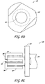
- the proximal end 320 of the drill bit 300 comprises a shaft 322 that is sized, shaped and otherwise configured to selectively mate with a corresponding portion of a bone drill (not shown).
- the shaft 322 comprises a generally triangular cross-sectional shape, as shown in FIG. 8D . However, in alternative arrangements, the shape, size and/or other details of the shaft can vary.
- the shaft 322 can include a standard or non-standard configuration. Bone drills with which the various drill bits disclosed herein are used can be either manually operated or power driven (e.g., mechanically, pneumatically, hydraulically, etc.).
- a distal end 330 of the drill bit 300 can include a flange 340 and one or more abrading members or cutters 356 extending distally from the flange 340.
- the drill bit 300 can comprise a total of three cutters 356 that are generally equally spaced apart (e.g., at angles of approximately 120° relative to one another).
- the quantity, size, shape, position, orientation, spacing and/or other characteristics or properties of the cutters 356 can be different than illustrated herein.
- a drill bit can include more or fewer cutters (e.g., 1, 2, 4, 5, more than 5), as desired or required.
- the cutters can be larger or smaller or can extend along different portions of the distal end of the drill bit.
- a drill bit can be cannulated, such that one or more passages or openings 326 extend (e.g., longitudinally) through the device.
- a passage 326 can generally extend from the proximal end of the drill bit 300 to the distal end, terminating in an opening 351 along the distal hub 352 to which the cutters 356 are secured.
- the inclusion of such passages or openings 326 can help ensure that the drill bit is accurately positioned within a patient's joint or other portion of the anatomy before commencing a drilling procedure.
- sharp edges formed along the distal and/or peripheral portions of the cutters 356 can abrade and remove cartilage, bone and/or other tissue that they engage and contact.
- the longitudinal distance D1 ( FIG. 8A ) between the distal face 341 of the flange member 340 and the distal ends of the cutters 356 can limit the depth of the recess or opening that is created within the patient's bone or other anatomical area.
- the peripheral surfaces of the cutters 356 can define a diameter or other cross-sectional dimension D2 ( FIG. 8A ) that effectively limits the diameter of the resulting recess or other openings in the patient's bone or other targeted tissue.
- each drill bit 300 can be configured to create an implant site having specific dimensions (e.g., depth, diameter, etc.). Consequently, in some arrangements, drill bits of varying size and shape are available to the surgeon or other clinician in order to accurately create a specific desired implant site within the patient.
- the distal edges and/or other surfaces of the cutting blades or cutters can be generally flat and/or otherwise contoured (e.g., to generally match and/or receive the base of the implant).
- the flange 340 can include one or more openings 344.
- abraded materials can stay clear of and not interfere with the working end of the drill bit, allowing the cutters 356 to continue to function normally.
- the cutters 356 can be joined along a hub 352 along or near the center of the distal face 341 of the flange 340. As shown, the cutters 356 can extend at least radially outwardly from the central hub 352, toward the outer periphery of the flange 340. As noted above, the radial length of the cutters 356 can help determine the diameter of the recess or opening that will be created within a patient's bone or other tissue. However, because of the generally vertical orientation of the peripheral edges 357 of the cutters 356, the corresponding implant opening that will be created by the drill bit 300 will be generally cylindrical. Therefore, additional implant site preparation is required in order to create an opening having a reverse taper shape.
- a drill bit having an articulating cutter or a movable cutting arm can be used to create the necessary taper or slope along the side walls of the recess or opening in a bone or other targeted region of the anatomy.
- the articulating cutter is configured to create a curved contour along the bottom and/or side surfaces of the recess.
- such curved surfaces can include one or more convex and/or concave portions, as desired or required.
- FIGS. 9A-9D One example of a drill bit 400 configured to create such a reverse tapered implant site is illustrated in FIGS. 9A-9D .
- the depicted drill bit 400 can comprise a main body portion 410 that terminates at or near a distal flange assembly 440.
- a proximal end of the drill bit 400 can comprise a shaft 420 that is sized, shaped and otherwise configured to engage and mate with a corresponding portion of a drill (not shown).
- a central hub 452 located along on near the distal face 441 of the flange 440 can help secure one or more stationary cutters 456 that are configured to abrade bone, cartilage and/or other tissue with which they come in contact.
- the arrangement illustrated in FIGS. 9A-9D comprises two stationary cutters 456 that are spaced generally opposite of each other (e.g., 180° apart).
- a drill bit comprises more or fewer stationary cutters, as desired or required.
- the drill bit 400 can additionally comprise one or more articulating cutters or movable cutting arms 460.
- a movable cutter 460 can be selectively deployed (e.g., radially outwardly about a hinge or other pivot point) in order to create a desired draft angle along the side of the implant site.
- the articulating cutter 460 is shown in the stowed or radially contracted position.
- the distal face 441 of the flange 440 will contact and abut an exterior surface of the bone or other site being drilled. This can prohibit the continued advancement of the cutters 456 and advantageously limit the depth of the resulting implant site.
- the surgeon or other clinician can cause the articulating cutter 460 to be deployed outwardly.
- the desired reverse taper or wedge shape can be created along the sides of the implant site.
- the articulating cutter 460 is moved outwardly by selectively retracting a sleeve 470 in the proximal direction (e.g., away from the flange 440 and the distal end of the drill bit, as generally represented in FIG. 9C by arrow P).
- the sleeve 470 includes a contoured grip portion 472 to allow the user to more easily grasp and retract the sleeve 470. Consequently, the articulating cutter 460 can be rotated or otherwise moved in a manner generally represented by arrow A. This permits the peripheral edge of the articulating cutter 460 to contact and abrade additional bone, cartilage and/or other tissue, thereby creating the desired reverse taper or truncated cone shape within the recess R ( FIG. 2 ).
- the articulating cutter 460 can assume a fully extended orientation in order to create the necessary taper to the adjacent side walls of the implant site.
- a sufficiently strong biasing or other type of force can be imparted on the articulating cutter 460 to ensure that it can reach the targeted fully deployed position.
- the articulating cutter 460 can be biased radially outwardly using a spring or other resilient member.
- any other force imparting device or method can be used to ensure that the articulating cutter 460 fully extends when selectively deployed by the clinician.
- the sleeve 470 can be returned to its original orientation (e.g., closer to the flange 440, as illustrated in FIG. 9A ), causing the articulating cutter 460 to move to its stowed or radially retracted position.
- the sleeve 470 is normally resiliently biased in the distal position (e.g., as illustrated in FIG. 9A ). Thus, in such configurations, as discussed above, a surgeon or other user needs to retract the sleeve 470 proximally relative to the main body portion 410 of the drill bit 400 in order to deploy the articulating cutter 460. As illustrated in FIG. 10A , the sleeve 570 is normally maintained in a distal orientation with the assistance of a spring 516 or other resilient member. In the illustrated example, the sleeve 570 includes a body portion 572 and an enlarged grip portion 574.
- a proximal end of the spring 516 can be coupled to a stop nut 512 coupled to or integrally formed with the main body portion 510.
- the sleeve 570 contacts the stop nut 512 to prevent further retraction once the articulating cutter 560 has been deployed.
- any other device or method can be used to normally maintain the position of the sleeve 470, 570 relative to adjacent portions of the drill bit 400, 500 (e.g., the main body portion 410, 510).
- the drill bit is configured to automatically deploy the articulating cutter in a outwardly oriented position once the flange of the drill bit contact the outer surface of the bone structure or other treatment site (e.g., once the cylindrical recess has been made to the desired depth).
- the articulating cutter can be deployed in its expanded position as a result of automatic mechanical actuation between the flange, cutter and/or other portion of the drill bit relative to the implant site.
- a reverse tapered recess can be created using a two or multi-step process. For example, as part of an initial step, a first drill bit can be used to create a generally cylindrical opening within a targeted bone.
- a drill bit that is configured to only create a generally cylindrical opening is illustrated and discussed herein with reference to FIGS. 7 and 8A-8C .
- a second drill bit having an articulating arm such as, for example, the bit discussed herein with reference to FIGS. 9A-9D and 10A-10D , can be inserted into the generally cylindrical opening. By moving the articulating cutter to its extended position, therefore, the desired wedge or reverse tapered shape can be created within the recess or implant site.
- a drill bit 500 can comprise a total of three stationary cutters 556 and an articulating cutter 560.
- a drill bit can comprise more or fewer stationary cutters 556 and/or articulating cutters 560, as desired or required by a particular application or use.
- the articulating cutter 560 can attach to the main body 510 and/or any other portion of the drill bit 500 using a hinge 564 or other pivot point.
- the articulating cutter 560 can be selectively rotated about such a hinge 564 between stowed and extended orientations.
- drill bits 400, 500 illustrated in FIGS. 9A-9D and 10A-10D can be advantageously used to create an implant site having a desired reverse taper or wedge design.
- Drill bits comprising articulating cutters can be introduced into the implant site after a generally cylindrical recess or opening has been created by a drill bit that does not include an articulating cutter (e.g., the drill bit shown in FIG. 7 ), as part of a two-step procedure.
- the drill bit can be advanced to the targeted drill site of the patient bone or other anatomical location with the assistance of a guide pin.
- any one of the drill bit arrangements disclosed herein can include a longitudinal lumen or other passage.
- a guide pin can be tamped at least partially into the surface of the bone to be drilled.
- the guide pin may be advanced through the patient's anatomy using a trocar or similar device.
- a cannulated drill bit as discussed herein, can be passed over the guide pin to ensure that the distal, working end of the drill bit is properly positioned relative to the treatment site (e.g., joint).
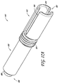
- an introducer 600 can include a generally cylindrical introducer tube 610 having an opening 620 through which the implant may be passed.
- the distal end 606 of the introducer tube 610 can comprise a neck or other narrowed portion 608.
- the neck portion 608 can include a wall 612 having a rounded distal edge 613.
- the neck portion 608 has a length (labeled 614 in FIG. 12B ) of about 0.155 inches to about 0.170 inches.
- the internal diameter of the introducer tube 610 can vary along its length.
- a proximal portion 618 of the introducer 600 comprises a flared shape, wherein the inside diameter of the opening 620 is progressively reduced in the proximal to distal direction.
- the opening 620 can maintain a generally constant inner diameter along a second, more distal portion 616 of the introducer tube 610.
- the inner diameter, length, other dimension and/or other details or properties of the introducer 600 can be different than shown in FIGS. 11 , 12A-12B and 13A-13B and described herein.
- the example embodiment illustrated in FIG. 14 comprises a longer flared interior portion 728 (e.g., relative to the adjacent generally cylindrical portion 726) than the introducer 600 of FIG. 12B .
- the neck portion 608 of the introducer tube 610 can be positioned at least partially within the opening or recess into which the implant will be secured.
- the introducer can be sized, shaped and otherwise configured to that the neck portion 608 fits generally snugly within the implant site.
- an implant 10 can be placed within the opening 628 along the proximal end 602 of the introducer 600. As shown, the implant 10 is advanced into the interior of the introducer 600 with its base or bottom 14 end first.
- a plunger or other pusher member can be inserted within the interior of the introducer to help push the implant through the introducer and into the implant site.
- Such a plunger or pusher member can be operated manually and/or with the assistance of an external power-assist device (e.g., mechanically, pneumatically, hydraulically, etc.), as desired or required.
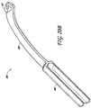
- a clinician can deliver the implant to the implant site using a mechanically-assisted delivery tool or introducer 800.
- a mechanically-assisted delivery tool or introducer 800 can comprise, among other things, an introducer tube 810, a plunger 820, a handle 830 and a clamp 840.
- Such mechanically-assisted delivery devices can be helpful in advancing the implant through the interior of an introducer tube against a relatively large resistance of back-pressure.
- a resistive force can be particularly high when the implant comprises a relatively large taper angle ⁇ .
- the delivery tool is capable of overcoming resistive forces of about 5 to about 20 pounds.
- the delivery tool exerts a force about 5 to about 25.
- the delivery device is operated by or with the assistance of one or more motors.
- the clamp is moved (e.g., rotated) relative to the handle using (or with the assistance of) one or more stepper motors and/or any other type of motor or actuator.
- Delivery of an implant through the introducer tube 810 is accomplished with at least some assistance from air or pneumatic pressure.
- air or other fluid can be injected into the interior of the introducer tube once the implant is inserted therein.
- the delivery of air can be incorporated into a plunger member 820 (e.g., via one or more interior lumens) so that the implant can be advanced through the introducer tube 810 into the implant site using mechanical force (e.g., by moving the plunger 820 through the tube 810) and/or by injecting air and/or other fluids into the interior of the tube 810.
- the fluid openings through the plunger 820 and/or any other fluid passages can be placed in fluid communication with a compressor or other fluid generating device. Advancement of the implant through the introducer tube 810 can be accomplished by applying a vacuum along or near the distal end of the tube 810 (e.g., through one or more vacuum ports along the introducer tube 810). Such vacuum ports or openings can be placed in fluid communication with a vacuum or other suction generating device.
- the delivery tool comprises one or more depth stop features or components to ensure that the implant being delivered to a target implant site is properly delivered into the target implant site.
- the depth stop features help protect the structural integrity of the implant as the implant is being inserted within the target anatomical implant site.
- the delivery device comprises and/or is operatively coupled to one or more pressure gauges or other pressure or force measuring devices, members or features.
- gauges or other measurement devices can help ensure that a maximum backpressure or force is not exceeded when operating the device. This can help protect the integrity of the implant (e.g., to ensure that the structural integrity, water composition and/or other properties of the implant are maintained), protect the delivery device, protect the user and/or the patient and/or provide one or more other advantages or benefits.
- the introducer tube 810 of the delivery tool or device 800 comprises one or more viewing windows that permit the implant to be viewed as it is being advanced through the device 800 to the implant site.
- the introducer tube 800 (and thus the longitudinal axis along which the implant is advanced through the delivery tool or device) is substantially perpendicular with the surface of the bone or other anatomical site into which the implant will be delivered and/or the handle 830 of the device 800.
- At least a portion of the interior of the introducer tube 810 comprises and/or is otherwise coated or lined with one or more absorbable or lubricious layers, materials and/or other substances. Such materials can help preserve the moisture level of the implant as it is being advanced through the introducer tube 810.
- the interior surface of the introducer tube can comprise a low coefficient of friction to facilitate the delivery of an implant through the delivery device or tool 800.
- the effective coefficient of friction along the interior of the introducer tube can be lowered polishing such surfaces.
- the introducer, including its interior surfaces can comprise surgical grade stainless steel.
- the delivery tool or device 800 is incorporated into the drill bit configured to create a reverse tapered implant site.
- a combination device can be coupled to a drill or other mechanical device to first create the implant site. Then, the combination device can take advantage of the mechanical output generated by the drill and/or other mechanical or motorized device to help urge the implant through the introducer tube of the combination device.
- the introducer tube 810 of the mechanically-assisted delivery tool 800 can be hollow and generally cylindrical in shape. However, the shape, general structure and/or other characteristics of the tube 810 can be different than disclosed herein.
- the introducer tube 810 comprises an externally threaded portion 814, a proximal portion 812 extending between a proximal end 802 and the externally threaded portion 814, and a distal portion 816 extending between the externally threaded portion 814 and a distal end 804.
- the distal end 804 of the introducer 810 can comprise a neck or other narrowed portion 806.
- the internal diameter of the introducer tube 810 can vary along at least a portion of the tube's length.
- the proximal portion 812 of the introducer or introducer tube 810 has a generally constant, consistent or flat inner diameter.
- the distal portion 816 of the introducer tube 810 can comprise a generally tapered or sloped portion 816a, such that the inside diameter of the tube is progressively reduced in the proximal to distal direction.
- the slope along the interior surface of the tube 810 can be generally linear.
- the slope of the interior surface of the tube 810 is at least partially non-linear (e.g., curved, rounded, irregular, etc.), either in addition to or in lieu of any generally linear and/or constant portions, as desired or required for a particular application or use.
- a portion 816b proximate the distal end 804 comprises a generally constant or flat (e.g., non-sloped) inner surface or diameter.
- the inner diameter or surface, length, other dimensions and/or other details or properties of the introducer tube 810 including any internal tapered or sloped portions 816a, any generally cylindrical (e.g., constant, flat, non-sloped, etc.) interior portions 816b, any neck portions 806 and/or the like can be different than shown in FIGS. 17A-17B and described herein.
- the proximal portion 812 of the introducer tube 810 includes one or more slits or other openings 818. As shown, such a slit 818 can begin adjacent to or near the externally threaded portion 814 of the tube 810 and can extend to or near the proximal end 802 of the tube 810.
- the proximal portion 812 of the introducer tube includes two (or more) slits 818 located opposite each other in the introducer 810 to form a channel through the proximal portion 812. In some examples, for example as shown in FIGS.
- the proximal portion 812 of the introducer tube 810 comprises a flange 819 or other protruding or flared portion extending outwardly (e.g., radially outwardly in a continuous or intermittent manner) from or near the proximal end 802.
- the flange or other protruding member 819 can be located along one or more other longitudinal locations of the tube 810, as desired or required.
- the flange 819 can be substantially or generally flat and/or can include any other shape (e.g., curved, fluted, etc.).
- the flange 819 can be integrally formed or attached to the proximal portion 812 of the tube 810.
- the flange 819 can be a separate member that can be selectively attached to or removed from the tube 810 and/or any other portion of the tool 800.
- the plunger 820 of the tool 800 can be generally cylindrical in shape with an enlarged proximal head portion 822 that includes a domed proximal end 824.
- the plunger 820 in a properly assembled mechanically-assisted delivery tool 800, is shaped, sized and otherwise configured to slide within the hollow interior passage of the introducer tube 810.
- a clinician or other user can selectively move the plunger within an interior portion of the introducer tube 810 in order to urge an implant (e.g., a tapered implant) through the distal end of the tube and into a targeted implant site of a patient.
- an implant e.g., a tapered implant
- the main body 826 of the plunger 820 can have a diameter approximately the same as and/or slightly smaller than the inner diameter of the neck portion 806 and distal portion 816b of the introducer 810.
- the head portion 822 of the plunger 820 includes a motion limiter or depth stop 828.
- the motion limiter 828 can comprise one or more knobs, protrusion members and/or other members or features that generally extend outwardly from the head portion 822 of the plunger.
- such a motion limiter, depth stop member or feature and/or other protruding member 828 is configured to slide within the slit(s) 818 or other openings of the introducer tube 810.
- the head portion 822 of the plunger 820 comprises a diameter approximately the same as and/or slightly smaller than the inner diameter of the proximal portion 812 of the introducer tube 810.
- the corresponding abutting features of the plunger 820 and the introducer tube 810 can advantageously help limit the depth to which an implant (e.g., tapered implant) can be delivered relative to an implant site of a patient. In some examples, this can help improve the safety and efficacy of the implant, the related tools and the implant procedure.
- an implant e.g., tapered implant
- the handle 830 of the delivery tool 800 comprises a generally circular internally threaded nut portion or introducer tube receiving portion 834.
- the threaded nut portion or introducer tube receiving portion 834 can be interposed between an elongate proximal section 832 and an elongate distal section 836.
- the introducer tube receiving portion 834 is located closer to the distal section 836 of the handle 830.
- the portion 834 can be located along any other portion of the handle 830, as desired or required.
- the introducer tube receiving portion 834 can include one or more other engagement or connection features or devices (e.g., snap connections, press-fit or friction-fit connections, screws or other fasteners, adhesives, etc.), either in lieu of or in addition to a threaded connection.
- engagement or connection features or devices e.g., snap connections, press-fit or friction-fit connections, screws or other fasteners, adhesives, etc.
- the proximal portion or section 832 of the handle can be longer than the distal portion or section 836.
- the introducer tube receiving portion 834 can be positioned closer to the distal end than the proximal end of the handle 830.
- the introducer tube receiving portion 834 is located at or near between the distal and proximal ends of the handle, or at, near or closer to the proximal end of the handle, as desired or required.
- the proximal section 832 and distal section 836 can extend in generally opposite directions from the nut or introducer tube receiving portion 834.
- a longitudinal axis of the distal section 836 is slightly offset from a longitudinal axis of the proximal section 832.
- Such a configuration can assist with the coupling of the clamp 840 as described herein.
- a centerline or orientation of the distal section or portion 836 of the handle is generally offset with respect to the centerline or orientation of the proximal section 832.
- the introducer tube receiving portion 834 can be sized, shaped and otherwise configured so that the distal section 816 of the introducer tube 810 can pass through the opening of the introducer receiving portion 834. Further, the externally threaded portion 814 of the introducer tube 810 can operatively engage and mate with the internal threaded portion of the introducer tube receiving portion 834. As noted above, the handle 830 can engage the introducer tube 810 using one or more other attachment methods, features or devices (e.g., fasteners, snap-fit or friction-fit connections, other mating connections or couplings, adhesives, etc.) either in addition to or in lieu of a threaded connection.
- features or devices e.g., fasteners, snap-fit or friction-fit connections, other mating connections or couplings, adhesives, etc.
- the elongate proximal section or portion 832 of the handle comprises a grasping portion 838 configured to be selectively gripped and manipulated by a user during use.
- the grasping portion 838 can be contoured, shaped and/or otherwise configured to improve the user's grip on the handle 830.
- the distal section or portion 836 of the handle comprises a generally rectangular cross-section.
- the distal portion and/or any other portion of the handle 830 can include any other shape (e.g., circular, oval, square, polygonal, etc.).
- the distal section 836 of the handle comprises a generally vertical shape so that it is taller than it is deep.
- the distal section 836 of the handle 830 comprises a keyhole 837 or other opening for coupling to the clamp 840 of the device.
- the keyhole 837 or other opening can be configured to allow the clamp 840 to be quickly and easily connected to and/or disconnected from the handle 830.
- the clamp 840 can be permanently or substantially permanently attached to the handle 830.
- the size, shape, orientation, and/or other details or properties of the handle 830 can be different than shown in FIGS. 19A-19B and described herein.
- the clamp 840 can comprise an elongate member having a slight curve.
- a proximal portion of the clamp 840 can include a handle or grasping portion 848 that a user can grip during use of the device.
- a distal portion 846 of the clamp 840 is generally sized, shaped and otherwise configured such that it can be moved within the slit 818 of the introducer tube 810.
- the distal end of the clamp 840 comprises a key 847 for insertion within the keyhole or other opening 837 of the handle 830 in order to couple the clamp to the handle.
- the handle 830 and the clamp 840 can be connected to one another about a hinge or other rotatable point, thereby permitting the handle to be selectively rotated and/or otherwise moved relative to the clamp.
- a relative rotation between the clamp and the handle can be used to provide the mechanical force necessary to move the plunger 820 within the introducer tube 810.
- This can advantageously urge an implant (e.g., tapered hydrogel implant) through the tube 810 and into a target recess of an implant site.
- the forces created by moving the clamp relative to the handle can help move an implant against relatively high back-forces (e.g., against relatively high friction and/or other resistive forces) within the introducer tube.
- Such movement of the implant can be particularly difficult for reverse tapered implants where at least a portion of such implants experiences generally high radially compressive forces while being moved through an interior lumen or other opening of the introducer tube 810.
- the user inserts the implant 10 (e.g., reverse tapered implant, other joint implant, etc.) into the introducer tube 810 via the proximal end 802.
- the plunger 820 can then be inserted into the proximal end 802 of the introducer tube 810 and used to distally advance the implant 10 within the introducer tube 810.
- the clamp 840 can be coupled to the handle 830 by inserting the key 847 (or other protruding portion or feature) of the clamp 840 into the keyhole 837 (or other opening) of the handle 830.
- the clamp 840 is generally positioned and movable within the slit 818 of the introducer tube 810.
- the clamp 840 can be rotatably attached to the handle 830 (e.g., at a hinge point), thereby allowing a user to selectively rotate or otherwise move the clamp relative to the handle (e.g., to move the clamp 840 toward or away from the handle 830 within the slit, groove or other opening of the introducer tube 810).
- an offset between the distal section 836 and proximal section 832 of the handle 830 permits the distal portion 846 of the clamp 840 to be aligned with the slit 818 in the introducer tube so that the clamp can be selectively moved within the slit 818 when the clamp 840 and handle 830 are coupled to one another (e.g., via the key 847-keyhole 837 joint or a similar feature or mechanism). Therefore, the delivery device 800 is configured for quick, easy and convenient assembly and disassembly for cleaning, sterilization, repair, maintenance and/or any other reason or purpose.
- the various components of the mechanically-assisted delivery device 800 comprise one or more rigid and/or semi-rigid materials that are configured to withstand the forces, moments, chemicals and/or other substances, temperature fluctuations and/or other elements to which they may be exposed.
- the components of the implant delivery device can comprise one or more metals (e.g., stainless steel, other surgical steel, other types of steel, etc.), alloys, plastics and/or the like. Such materials can permit the device to be autoclaved, sterilized or otherwise cleaned during a specific disinfection protocol.
- the structural and other physical characteristics of the device can permit the user to exert the necessary forces using the device to deliver implants of various sizes, shapes and/or configurations through the corresponding introducer tube and into a target implant site of a patient.
- the distal neck portion 806 of the introducer tube 810 can be positioned at least partially within the opening, recess or other implant site into which the implant 10 will be secured.
- the introducer tube 810 is sized, shaped and otherwise configured to that the neck portion 806 fits generally snugly within the implant site.
- the user can urge the clamp 840 toward the handle 830 of the device (e.g., so that the clamp rotates or otherwise moves relative to the handle).
- a portion of the clamp 840 contacts the plunger 820 (e.g., the domed proximal end 824), and urges the plunger 820 distally within the introducer tube 810.
- such a movement urges the implant 10 distally within the introducer tube 810.
- the implant 10 may become radially compressed by the interior shape (e.g., tapered portion 816a) of the introducer tube 810. If sufficient force is applied to the implant 10 by moving the clamp relative to the handle, the implant 10 can pass through the neck portion 806 of the introducer tube and into the implant site.
- the motion limiter 828 or similar feature of the plunger 820 can contact the distal end of the slit or similar opening 818 of the introducer tube 810 when the implant 10 has been released from the delivery device 800 into the implant site. As depicted in FIG. 21C , this can help prevent the plunger 820 from continuing to move toward and into the implant site and possibly damaging the implant site and/or the implant 10. While the user grasps the handle 830 and the clamp 840 with one hand, he or she can apply a required force on the flange 819 that extends outwardly from the proximal end 802 of the introducer tube 810 with the other hand to stabilize and control the introducer 810.
- the mechanically-assisted delivery devices disclosed herein can facilitate the compression and delivery of reverse tapered implants within a target implant site.
- the mechanically-assisted delivery device can be configured to be operated at least partially with the assistance of a mechanical motor, a pneumatic device and/or another external device.
- the clamp of the device can be moved relative to the handle by or with the assistance of one or more motors (e.g., regulated by a user using a button, knob, dial and/or other controller).
- Such examples can further facilitate the delivery of implants within an implant site of a patient.
Description
- This application relates generally to anatomical implants, and more specifically, to hydrogel joint implants.
- Implants are often used to replace deteriorated or otherwise damaged cartilage within a joint. Such devices can be used to treat osteoarthritis, rheumatoid arthritis, other inflammatory diseases, generalized joint pain and/or other joint diseases. To ensure proper function and long term effectiveness, such implants should be properly secured within a patient's bone or other implant site.
- The implant is used in a method of treating a joint of a patient, comprising creating a recess, hole or other opening in a bone located at or near a targeted joint, wherein the recess comprises a generally wedge, reverse tapered, truncated frustum shape in which the bottom of the recess comprises a larger diameter or other cross-sectional dimension than a top of the recess. The recess or other opening in the bone comprises a surface opening along an outer surface of the bone, a bottom opening along the distal end of the recess and side walls that generally extend between the surface opening and the bottom opening, wherein a diameter or other cross-sectional dimension of the bottom opening is larger than a diameter or other cross-sectional dimension of the surface opening.
- The method further comprises at least partially radially compressing a joint implant having a wedge or truncated frustum shape, wherein the joint implant comprises a first end and a second end and a body extending between the first end and the second end. The second end of the implant is generally opposite of the implant's first end. When the joint implant is in a radially uncompressed state, a diameter or other cross-sectional dimension of the first end is smaller than a diameter or other cross-sectional dimension of the second end. The method further comprises inserting the joint implant within the recess, while the joint implant is in a radially compressed state, wherein the second end of the joint implant is inserted first within the recess. The second end of the joint implant is adjacent the bottom opening of the recess, and the first end of the joint implant is adjacent the surface opening of the recess when the joint implant is properly positioned within the recess. The method further comprises releasing the joint implant from a radially compressed state to a less compressed state, when the joint implant is properly positioned within the recess, wherein, when the joint implant is in a less compressed state, the diameter or other cross-sectional dimension of the second end of the joint implant is larger than the diameter or other cross-sectional dimension of the surface opening of the recess. When the joint implant is in a radially uncompressed state, the body of the joint implant imparts a radial force at least partially along the side walls of the recess, thereby securing the joint implant within the recess.
- According to the invention, the hydrogel implant configured for implantation within a joint of a patient comprises a top end configured to form an articulation surface when properly implanted within a joint, a bottom end generally opposite of the top end and a main hydrogel body extending between the top end and the bottom end and having a longitudinal centerline. The diameter of the bottom end is greater than a diameter of the top end and side walls generally extend between the top end and the bottom end, such that the side walls are generally sloped relative to the longitudinal centerlin and flat. In one embodiment, the implant comprises a tapered shape due to, at least in part, to a difference between the diameters of the top end and the bottom end. In some embodiments, the implant is configured for placement within an implant site having a similar reverse tapered or wedge shape, thereby reducing the likelihood of unintentional removal of the implant from the implant site following implantation.
- According to some embodiments, the hydrogel comprises polyvinyl alcohol (PVA). In some embodiments, the content of PVA and/or other substances is 35% to 45% by weight. In some embodiments, the content of PVA is approximately 40% by weight. In one embodiment, the implant is load bearing and generally non-biodegradable. In some embodiments, the implant is configured for placement within at least one of a toe, finger, ankle, knee, shoulder, hip or other joint. According to the invention, a transition between the top end and the side walls is generally curved or otherwise smooth. In one embodiment, the top end of the implant is approximately 5 mm to 20 mm in diameter. In one embodiment, a diameter of the bottom end is approximately 10% to 15% larger than a diameter of the top end. In some embodiments, a distance between the top end and the bottom end of the implant is approximately 4 mm to 16 mm. In one embodiment, a ratio of the diameter or other cross-sectional dimension of the bottom end of the implant to the diameter or other cross-sectional dimension of the top end of the implant is approximately between 1.05 and 1.3. In one embodiment, a ratio of the diameter or other cross-sectional dimension of the bottom end of the implant to the diameter or other cross-sectional dimension of the top end of the implant is at least 1.1.
- These and other features, aspects and advantages of the present application are described with reference to drawings of certain embodiments, which are intended to illustrate, but not to limit, the various inventions disclosed herein. It is to be understood that the attached drawings are for the purpose of illustrating concepts and embodiments of the present application and may not be to scale.
Figures 3A - 21C illustrate implants and instrumentation that does not form part of the invention. -
FIG. 1 schematically illustrates a side view of a tapered implant according to the invention; -
FIG. 2 schematically illustrates a side view of the implant ofFIG. 1 positioned within a corresponding implant site, according to the invention; -
FIG. 3A illustrates a side view of a tapered implant; -
FIG. 3B illustrates a top view of the tapered implant ofFIG. 3A ; -
FIG. 4 illustrates a top view of an open mold assembly for making tapered implants; -
FIGS. 5 and 6 illustrate side views of the mold assembly ofFIG. 4 ; -
FIG. 7 illustrates a perspective view of a drill bit configured for use with a bone drill; -
FIGS. 8A and 8B illustrate side views of the drill bit ofFIG. 7 ; -
FIG. 8C illustrates a distal end view of the drill bit ofFIG. 7 ; -
FIG. 8D illustrates a cross sectional view of the proximal shaft portion of the drill bit ofFIG. 7 ; -
FIG. 8E illustrates a detailed side view of the distal working end of the drill bit ofFIG. 7 ; -
FIG. 9A illustrates a side view of one embodiment of a drill bit with an articulating cutter in a stowed or retracted orientation; -
FIG. 9B a distal end view of the drill bit ofFIG. 9A ; -
FIG. 9C illustrates a side view the drill bit ofFIG. 9A with its articulating cutter in an extended or deployed orientation; -
FIG. 9D a distal end view of the drill bit ofFIG. 9C ; -
FIG. 10A illustrates a side view of one embodiment of a drill bit with an articulating cutter in a stowed or retracted orientation; -
FIG. 10B a distal end view of the drill bit ofFIG. 10A ; -
FIG. 10C illustrates a side view the drill bit ofFIG. 10A with its articulating cutter in an extended or deployed orientation; -
FIG. 10D a distal end view of the drill bit ofFIG. 10C ; -
FIG. 11 illustrates a perspective view of an implant introducer; -
FIG. 12A illustrates a side view of the introducer ofFIG. 11 ; -
FIG. 12B illustrates a longitudinal cross-sectional view of the introducer ofFIG. 11 ; -
FIG. 13A illustrates a distal end view of the introducer ofFIG. 11 ; -
FIG. 13B illustrates a detailed view along the neck portion of the introducer depicted inFIG. 11 ; -
FIG. 14 illustrates a longitudinal cross-sectional view of another implant introducer; -
FIGS. 15A-15C illustrate time-sequential side views of an implant being inserted within an implant site using the introducer ofFIG. 11 ; -
FIG. 16A illustrates a perspective view of an assembled implant delivery tool; -
FIG. 16B illustrates an exploded view of the delivery tool ofFIG. 16A ; -
FIG. 16C illustrates a cross-sectional view of the delivery tool ofFIG. 16A ; -
FIG. 16D illustrates a perspective view of an assembled implant delivery tool; -
FIG. 16E illustrates an exploded view of the delivery tool ofFIG. 16D ; -
FIG. 17A illustrates a perspective view of an introducer; -
FIG. 17B illustrates a cross-sectional view of the introducer ofFIG. 17A ; -
FIG. 18 illustrates a side view of a plunger; -
FIG 19A illustrates a perspective view of a handle; -
FIG. 19B illustrates a top view of the handle ofFIG. 19A ; -
FIG. 20A illustrates a side view of a clamp; -
FIG. 20B illustrates another view of the clamp ofFIG. 20A ; and -
FIGS. 21A-21C illustrate sequential views of an implant being moved through and deployed from a delivery tool. - The discussion and the figures illustrated and referenced herein describe various embodiments of a cartilage implant particularly well suited to replace deteriorated or otherwise damaged cartilage within a joint. Such implants are configured to remain within the patient's joint on a long-term basis (e.g., for most or all of the life of the patient), and as such, are configured, in some embodiments, to replace native cartilage. Thus, in some embodiments, the implants are configured to be substantially non-biodegradable and/or non-erodable. For example, an implant is configured to remain within the patient's joint or other portion of the anatomy for a minimum of 20 to 100 years (e.g., about 20, 25, 30, 35, 40, 45, 50, 55, 60, 65, 70, 75, 80, 85, 90, 95, 100 years, durations between the foregoing values, etc.) without losing its structural and/or physical properties and/or without losing its ability to function as a cartilage replacement component or device. In other examples, the implants are configured to remain within the anatomy for greater than 100 years without losing its structural and/or physical properties and/or without losing its ability to function as a cartilage replacement component. Accordingly, such implants can be used to treat osteoarthritis, rheumatoid arthritis, other inflammatory diseases, generalized joint pain and/or other joint diseases.
-
FIG. 1 schematically illustrates one embodiment of animplant 10 intended for placement within a joint of a patient (e.g., toe, finger, ankle, knee, hip, shoulder, etc.). As shown, theimplant 10 includes a generally tapered overall shape, wherein itsbase surface 14 is larger than the opposite,top surface 16. As discussed in greater detail below, the smaller,top surface 16 comprises the articulation surface (e.g., a surface that is at least partially exposed to a joint), whereas the larger bottom orbase surface 14 is securely retained within a corresponding opening specially created in the anatomy (e.g., through bone, cartilage, other native tissue, etc.). As a result of such a design, thesides 18 of theimplant 10 comprise a taper angle θ (e.g., relative to generally vertical sides), thereby giving the implant a generally truncated frustum-like shape. As discussed in greater detail herein, such a reverse-taper, wedge or truncated frustum shape can help ensure proper securement of theimplant 10 within a patient's anatomy. -
FIG. 2 schematically illustrates animplant 10 similar to the one depicted inFIG. 1 snugly positioned within a corresponding recessed area R of a patient's tissue T (e.g., bone, cartilage, etc.). Such a recessed area R is formed at the patient's joint so that theimplant 10 can be used to replace and/or augment damaged cartilage (e.g., on a long-term or permanent basis, as discussed above). Any of the implants disclosed herein can be used in a human or animal anatomy for a variety of different indications or other purposes, such as, for example, joint therapy, reconstructive surgery, tissue augmentation, cosmetic surgery or the like. Theimplant 10 can be load bearing or non-load bearing, as desired or required. In some embodiments, once implanted within the anatomy, theimplant 10 is configured to be non-biodegradable for at least the expected useful life of theimplant 10. In some embodiments, theimplant 10 is adapted to generally retain its general structure, shape, structure, size, strength, compressibility, function and/or other properties during the life of the patient into which the implant is inserted. For example, theimplant 10 can be configured to generally maintain its original physical, chemical, biocompatibility and/or characteristics for at least about 100 years. In some examples, the implant retains the same or substantially the same water content, resiliency, durability, strength, coefficient of friction and/or any other properties for the period of time that it is positioned within the anatomy of the patient. In other examples, theimplant 10 is configured to generally maintain its original physical, chemical, biocompatibility and/or characteristics for less or more than about 100 years (e.g., about 50 years, 60 years, 70 years, 80 years, 90 years, 110 years, 120 years, 130 years, 150 years, 200 years, more than about 200 years, less than about 50 years, etc.), as desired or required. In some examples theimplant 10 is configured to resist or substantially resist biodegradation or mass reduction during such target time period. - With continued reference to
FIG. 2 , during delivery of theimplant 10 within the recess, theimplant 10 can be compressed inwardly (e.g., as schematically depicted by the arrows 20). Some methods of delivering such implants within an appropriately sized and shaped recess are discussed in greater detail herein. Once theimplant 10 has been properly positioned within the recess R, theimplant 10 is permitted to expand outwardly, thereby filling in or otherwise encompassing all or substantially all of the volume of the recess R. In some embodiments, the diameter or other cross-sectional dimension of thebase 14 of theimplant 10 is greater than the corresponding diameter or other cross-sectional dimension of the recess R. This helps prevent theimplant 10 from moving out of the recess after implantation. The reverse tapered shape of theimplant 10 and the recess R into which it is placed can help ensure thatimplant 10 remains securely within the recess R following implantation. In some embodiments, the outwardly directed forces of theimplant 10 in the direction of the adjacent interior surfaces of the recess R assist in maintaining theimplant 10 within the recess R during use (e.g., after implantation). - The shape of the
ends implant 10 can be generally flush with the adjacent tissue surface. However, in other examples, the top 16 of theimplant 10 extends above the adjacent tissue T (e.g., as illustrated inFIG. 2 ) or below the adjacent tissue T following implantation. For example, in one example, the top 16 of the implant is slightly "proud" or raised relative to the adjacent tissue (e.g., cartilage) in order to reestablish a desired contour of the damaged joint surface. In some examples, such a raised or otherwise protruding configuration can assist in creating a smoother transition between the exposed surface of theimplant 10 and adjacent native cartilaginous surfaces of a joint. - The top and/or bottom surfaces 16, 14 of the
implant 10 can be generally flat or planar. In other examples, thesurface - Another
tapered implant 110 configured to replace or augment damaged cartilage within a patient is illustrated inFIGS. 3A and 3B . As shown, theimplant 110 can comprise a bottom orbase surface 114 and atop surface 116, which is at least partially exposed to adjacent anatomical tissues (e.g., other cartilaginous surfaces, bone, other portions that function as an articulating surface of a joint, etc.) after implantation. As with the implant ofFIGS. 1 and 2 , the depicted implant includes a base 114 that is generally wider or otherwise larger than thetop surface 116. For example, the diameter or other comparable cross-sectional dimension of the base can be larger than that of the top. Accordingly, theimplant 110 includes generally slopedsides 118 that terminate in atop surface 116 of small diameter (or other cross sectional dimension) than that of the base orbottom surface 114. The sloped surfaces are generally flat or curved. Further, as shown inFIG. 3A , the transition between thesides 118 and the top 116 can be rounded or otherwise smooth. However, thetransition 117 from the side surfaces 118 to the top 116 of theimplant 110 can be more or less smooth than illustrated inFIG. 3A . In other words, in some examples, the radius of the curved corners is larger or smaller than disclosed herein. - As discussed herein with reference to
FIGS. 1 and 2 , the top, bottom and/or side surfaces of theimplant 110 can be generally planar (e.g., flat) or non-planar (e.g., curved, concave, convex, undulating, fluted, etc.), as desired or required. Further, although not illustrated inFIG. 3A , the recess or other opening in which theimplant 110 will be positioned can include a similar reverse-tapered shape (e.g., having a wider or large base and a smaller top) to help ensure that theimplant 110 remains securely in place following implantation. Additional details regarding reverse tapered openings within a patient's anatomy (e.g., bone), including details related to tools and methods that help create such openings, are provided below. - With continued reference to
FIGS. 3A and 3B , animplant 110 can include a generally circular or oval cross-sectional shape. Thus, in some examples, theimplant 110 is generally shaped like a frustum, truncated cone, cylinder and/or the like. However, the overall shape of the implants can vary depending on the specific application or use. For example, the shape of the base (or bottom), top and/or any other cross-sectional area of the implant can be generally rectangular (e.g., square), other polygonal, irregular or the like. - Regardless of its exact size and shape, the base portion can be larger or wider than the top of the implant in order to help ensure that the implant remains securely positioned within a targeted portion of a patient's anatomy (e.g., a joint) following implantation. For example, in some embodiments, the dimension (or area) of the base or bottom of the implant is approximately 10% to 15% (e.g., about 10%, 11%, 12%, 13%, 14%, 15%, ranges between such values, etc.) longer, wider or otherwise larger than the top of the implant. In implants having generally circular bottom and top surfaces, such as, for example, the
implant 110 illustrated inFIGS. 3A and 3B , the diameter of the base orbottom 114 is approximately 10% to 15% (e.g., about 10%, 11%, 12%, 13%, 14%, 15%, ranges between such values, etc.) larger than the diameter of the top 116. In other implants, the base 114 can be more than about 15% larger or less than about 10% larger than the top 116, as desired or required. For example, in some examples, the diameter (or other cross-sectional dimension) of thebase 114 is larger than the diameter (or other cross-sectional diameter) of the top 116 by approximately 1%, 2%, 3%, 4%, 5%, 6%, 7%, 8%, 9%, less than 1%, other values between the foregoing percentages and/or the like. Alternatively, the diameter (or other cross-sectional dimension) of thebase 114 is larger than the diameter (or other cross-sectional diameter) of the top 116 by approximately 16%, 17%, 18%, 19%, 20%, 25% 30%, 35%, 40%, 50%, 60%, more than 60% and/or the like. According to some examples, for any of the implant arrangements disclosed herein, the ratio of the diameter (or other cross-sectional dimension) of the base 114 to the diameter (or other cross-sectional dimension) of the top 116 of the implant is between about 1 and about 1.3 (e.g., approximately or more than 1.05, 1.06, 1.07, 1.08, 1.09, 1.1, 1.11, 1.12, 1.13, 1.14, 1.15, 1.16, 1.17, 1.18, 1.19, 1.2, 1.21, 1.22, 1.23, 1.24, 1.25, 1.26, 1.27, 1.28, 1.29, 1.3, values between the foregoing ratios, etc.). In other examples, the ratio is between about 1 and 1.05 (e.g., approximately or greater than 1.01, 1.02, 1.03, 1.04, 1.05), or greater than about 1.3 (e.g., approximately or more than 1.3, 1.35, 1.4, 1.45, 1.5, 1.55, 1.6, greater than 1.6, etc.), as desired or required. - As discussed above with reference to the implants illustrated in
FIGS. 1-3B , an implant having a wedge or reverse tapered design (e.g., an implant having a larger base than top) can help prevent or reduce the likelihood of unintended ejection or other escape from the implant site after implantation. Thus, in some examples, the push-out force (e.g., the force necessary to eject or otherwise remove the implant from the implant site) is advantageously increased for wedge shaped implants relative to implants that do not include a wedge or reverse taper design (e.g., cylindrical implants, right angle implants, implants having generally vertical sides, etc.). As a result, the likelihood of maintaining such embodiments within a joint or other part of the anatomy after implantation is advantageously increased. - With continued reference to
FIG. 2 , the implant can be positioned within a recess or other opening formed within the patient's bone, cartilage or other tissue. As shown, in some embodiments, theimplant 10 is sized, shaped and otherwise configured to fill all or most of the volume of the recess R once properly inserted therein. Further, according to some embodiments, the implant is radially oversized relative to the corresponding implant site (e.g., recess, opening, etc.) into which it will be placed. For example, an implant can be radially oversized by approximately 5% to 15% (e.g., about 5%, 6%, 7%, 8%, 9%, 10%, 11%, 12%, 13%, 14%, 15%, other percentages between such values, etc.) relative to the implant site. In alternative examples, an implant can be radially oversized by less than about 5% or more than about 15%, as desired or required. In such oversized examples once implanted, the implant can exert a radial or other outwardly directed force on the corresponding recess. Such a configuration can help ensure that the implant remains securely within the recess after implantation. In yet other examples, the implant comprises a similar or identical size as the implant site or is generally radially undersized relative to the implant site. - As a result of the shape of the implant and the corresponding implant site (e.g., recess, other opening, etc.), it may be necessary to radially compress the implant (e.g., inwardly, as schematically illustrated by the
arrows 20 inFIG. 2 ) in order to insert the implant within the implant site. Accordingly, one or more introducers or other delivery tools can be used to facilitate the placement of a tapered implant within an implant site. Additional inwardly-directed compressive forces on the tapered implant may be required for implants that are radially oversized relative to the target implant site, as discussed above. The degree to which an implant can be compressed (e.g., circumferentially, radially inwardly, etc.) may depend on one or more factors, properties, characteristics and/or other considerations, such as, for example, implant size, water content, ingredients and other components, strength, elasticity, surrounding temperature, method of manufacturing and/or the like. - According to some examples, radial compression of an implant can affect the implant's overall height, the shape or contours of its outer surfaces (e.g., top or articulating surface, base or bottom surface, sides, etc.) and/or one or more other properties or characteristics of the implant. By way of example, radial compression of an implant causes the height of the implant to increase (e.g., relative to the height of the implant when it is not radially compressed). Consequently, careful consideration may need to be given to the design of the implant based on, among other things, the expected level of radial compression that may occur once the implant has been properly secured within the implant site. Therefore, the amount of radial compression, and thus its effect on the implant's diameter, height, other dimensions, shape and/or other properties, may need to be carefully determined prior to implantation. Otherwise, upon implantation, an implant may not properly align with adjacent cartilage or other tissue surfaces in a joint or other anatomical location.
- According to some embodiments, any of the implant embodiments disclosed herein comprise polyvinyl alcohol (PVA) hydrogels. The implants can comprise one or more other materials in addition to PVA, such as, for example, other hydrogels, other polymeric materials, other additives and the like. In some embodiments, the PVA content of a hydrogel is approximately 40% by weight. However, the PVA content of an implant can be less or more than about 40% by weight (e.g., approximately 10%, 15%, 20%, 25%, 30%, 32%, 34%, 36%, 37%, 38%, 39%, 41%, 42%, 43%, 44%, 46%, 48%, 50%, 55%, 60%, 65%, 70% by weight, less than about 10% by weight, more than about 70% weight, values between the foregoing ranges, etc.), as desired or required.
- Further, the implants can comprise water, saline, other liquids, combinations thereof and/or the like. The use of saline within a hydrogel implant may be preferred over water, because, under certain circumstances, saline can help maintain osmotic balance with surrounding anatomical tissues following implantation. The exact composition of an implant (e.g., PVA or other hydrogel materials, water, saline or other liquids, other additives, etc.) can be selected so as to provide the resulting implant with the desired or required strength, load bearing capacity, compressibility, flexibility, longevity, durability, resilience, coefficient of friction and/or other properties and characteristics.
- In several examples, the implants disclosed herein are configured for drug delivery and/or are seeded with growth factors and/or cells. In some examples, the implants comprise one or more of the following: chondrocytes, growth factors, bone morphogenetic proteins, collagen, hyaluronic acid, nucleic acids, and stem cells. Such factors and/or any other materials included in the implant and selectively delivered to the implant site can help facilitate and promote the long-term fixation of the implant within the joint or other target area of the anatomy.
- In some examples, the implants disclosed herein are configured for anchoring during implantation. The implant can comprise one or more anchor sites (which may comprise non-hydrogel portions or tabs) to facilitate anchoring (e.g., suturing, stapling, etc.). In one example, the implant is pre-coupled to one or more anchors. Such anchors can comprise removable and/or permanent fixtures. In some examples, the anchors are resorbable or otherwise dissolvable after implantation (e.g., following a particular time period, such as, for instance, 1-30 days, 2-30 weeks, 6-12 months, 1-5 years, greater than 5 years, less than 1 day, etc.). In one example, the implant comprises at least one abrasive surface. In one example, the implant comprises one or more adhesive components. In other embodiments, the tapered shape of the implant permits secure implantation without the need for any anchoring or other fixation. In some examples, for any of the implants disclosed herein, one or more implant surfaces can be configured to promote bone adhesion by one or more coatings, substances and/or the like and/or by using an appropriate surface texture along the surface(s). For example, the implant surface can be roughened, can include pores (e.g., superficial pores) and/or any other feature, as desired or required.
- In some examples, the implants disclosed herein are supported or reinforced by a rigid support frame, such as a ceramic or metallic frame. In some examples, the implants disclosed herein are supported or reinforced by a flexible or rigid mesh structure. In other embodiments, the implants do not contain any support or reinforcement structure.
- Any of the implants disclosed herein can be manufactured using freeze/thaw cycling and/or any other production method. For example, a hydrogel formulation comprising water, saline, PVA (and/or other hydrogel materials), other polymeric materials, other additives and/or the like can be heated and/or otherwise treated as part of a freeze/thaw manufacturing process. In one example, a hydrogel solution comprising saline and about 40% PVA by weight is heated to approximately 121 °C under elevated pressure conditions (e.g., to affect dissolution of the polymer). For example, such a solution can be autoclaved in order to facilitate complete or substantially complete dissolution of the PVA in the saline, water and/or other liquid. Next, the temperature and/or pressure of the solution can be lowered to permit entrapped air and/or other gases to escape. In one example, after the autoclaving or similar step, the solution is generally maintained at a temperature of approximately 95 °C and atmospheric pressure for a predetermined time period.
- The solution can then be transferred (e.g., pumped, poured, etc.) into open molds where, once set, will form the desired shape of the implants. One example of such an
open mold assembly 200 is illustrated inFIGS. 4-6 . As shown, theopen mold assembly 200 can include a plurality ofindividual mold cavities 210, each of which is configured to receive a hydrogel solution. With specific reference to the cross sectional views ofFIGS. 5 and 6 , the hydrogel solution is configured to fill only alower portion 216 mold'sassembly cavities 210. Alternatively, the cavities can be filled with the desired hydrogel solution to a level that is above thelower portion 216. Accordingly, under such circumstances, the resulting device that is formed therein will extend into theupper portion 212 of thecavity 210. As described in greater detail below, any part of the device that extends above thelower portion 216 can be removed in order to produce an implant having generally sloped or contoured side walls and a reverse tapered design, in accordance with various implant arrangements disclosed herein. - With continued reference to
FIGS. 4-6 , thecavities 210 of themold assembly 200 can be shaped, sized and otherwise configured so that the implants formed therein comprise a wedge, truncated cone or reverse taper design. For example, in such designs, the base ends of the implants are generally larger than the corresponding, opposite top ends. Once the implants have been molded, they can be removed from the upper ends of theassembly 200. The molded items can be removed either after initial formation or after they undergo additional treatment (e.g., freeze/thaw cycling, other heat and/or pressure treatment, etc.). As noted above, depending on how much hydrogel solution is placed in the cavities, the molded implants removed from thecavities 210 of theassembly 200 may need to be cut, altered or otherwise processed. For example, in some embodiments, any portion of the implants formed by the generally cylindrical cavity section in theupper portion 212 of the cavities may need to be excised and discarded as part of a subsequent reshaping step. Accordingly, the remaining implants can generally resemble the shape of the implants ofFIGS. 3A and 3B or any other implant having a generally reverse taper or wedge design. - Due in part to the remaining production steps, accommodation of any changes in size (e.g., expansion, contraction, etc.) that may occur or are likely to occur to the implants can be considered during manufacturing by properly sizing and otherwise designing the
mold assembly 200. The amount of contraction or expansion of the implants can be based on one or more factors or conditions, such as, for example, the number of freeze/thaw cycles to which the implants are subjected, the temperature and/or pressure ranges associated with the remaining steps and/or the like. - Alternatively, the implants can be formed, at least in part, using an injection molding process and/or any other molding or casting procedure. In such injection or transfer molding techniques, once the hydrogel or other implant solution has been prepared, it can be loaded into an injection cylinder or other container of a molding press. The solution can then be forcibly transferred into a closed mold assembly using a pneumatic or hydraulic ram or any other electromechanical device, system or method. The hydrogel and/or other solution or implant component is injected into a corresponding closed mold assembly through a standard runner and gate system. Injection molding of implants can provide one or more benefits relative to open mold assemblies. For instance, the devices formed as part of the injection molding techniques typically do not require additional cutting, reshaping, resizing and/or processing, as they are essentially in their final shape immediately after the injection molding step has been completed.
- Regardless of how the implants are molded or otherwise shaped or manufactured, they can be subsequently subjected to one or more freeze/thaw cycles, as desired or required. For example, the implants, while in their respective mold cavities, are cooled using a total of four freeze/thaw cycles wherein the temperature is sequentially varied between approximately -20 °C and 20 °C. However, the number of freeze/thaw cycles, the temperature fluctuation and/or other details related to cooling the implants can be different than disclosed herein, in accordance with a specific production protocol or implant design.
- Following freeze/thaw cycling, the implants can be removed from their respective mold cavities and placed in one or more saline and/or other fluid (e.g., other liquid) baths where they can be subjected to additional cooling and/or other treatment procedures (e.g., to further stabilize the physical properties of the implants). For instance, the implants undergo an additional eight freeze/thaw cycles while in saline. Such follow-up cooling procedures are either different (e.g., more or fewer freeze/thaw cycles, different type of bath, etc.) or altogether eliminated from the production process, as desired or required.
- When the cooling (e.g., freeze/thaw cycling) and/or other treatment steps have been completed, the implants can be inspected to ensure that they do not include any manufacturing flaws or other defects. Further, at least some of the implants can be subjected to selective testing to ensure that they comprise the requisite physical and other characteristics, in accordance with the original design goals and target parameters for the implants. Further, it may be necessary to cut or otherwise process the implants in order to remove any excess portions. The completed implants are packaged in hermetically sealed plastic trays (or other containers) comprising foil or other types of lids or covering members. A volume of saline and/or other liquid can be included within such trays or other containers to ensure proper hydration of the implants during storage and/or any other steps preceding actual use. In one examples the implant trays or other containers are terminally sterilized using e-beam exposure between about 25 and 40 kGy. Additional details related to producing hydrogel implants can be found in
U.S. Patent Nos. 5,981,826 and6,231,605 . - According to some examples, the overall height (e.g., between the base or bottom surface and the top or articulating surface) of a tapered implant is approximately 10 mm. Further, the diameter or other cross-sectional dimension along or near the top surface of the implant can be about 10 mm. However, the height, diameter and/or other dimensions of a wedge-type implant can vary, as desired or required. For example, implants adapted for use in larger joints (e.g., knee, shoulder, hip, etc.) can have a height and/or diameter larger than 10 mm (e.g., about 11 mm, 12 mm, 13 mm, 14 mm, 15 mm, 16 mm, 18 mm, 20 mm, greater than 20 mm, dimensions between the foregoing values, etc.). Likewise, implants configured for use in smaller joints (e.g., toes) can be smaller than 10 mm in height (e.g., about 2 mm, 4 mm, 6 mm, 8 mm) and/or 10 mm in top diameter (e.g., about 2 mm, 4 mm, 6 mm, 8 mm).
- As discussed above with reference to
FIGS. 1 and 2 , in order to ensure that the implant securely remains within a joint or other anatomical location following implantation, the implant can be positioned within an implant site that also comprises a similar reverse taper, wedge or truncated cone shape. Accordingly, examples of making such a tapered recess or other opening within bone tissue are described in greater detail below. -
FIGS. 7-8B illustrate adrill bit 300 that can be used to create a reverse taper recess into which an implant may be positioned. As shown, thedrill bit 300 can comprise amain body portion 310 that extends at least partially along the longitudinal dimension of thedrill bit 300. Theproximal end 320 of thedrill bit 300 comprises ashaft 322 that is sized, shaped and otherwise configured to selectively mate with a corresponding portion of a bone drill (not shown). Theshaft 322 comprises a generally triangular cross-sectional shape, as shown inFIG. 8D . However, in alternative arrangements, the shape, size and/or other details of the shaft can vary. Theshaft 322 can include a standard or non-standard configuration. Bone drills with which the various drill bits disclosed herein are used can be either manually operated or power driven (e.g., mechanically, pneumatically, hydraulically, etc.). - With continued reference to
FIGS. 7 ,8A and 8B , and as shown in the detail view ofFIG. 8E , adistal end 330 of thedrill bit 300 can include aflange 340 and one or more abrading members orcutters 356 extending distally from theflange 340. As best illustrated in the front view ofFIG. 8C , thedrill bit 300 can comprise a total of threecutters 356 that are generally equally spaced apart (e.g., at angles of approximately 120° relative to one another). However, the quantity, size, shape, position, orientation, spacing and/or other characteristics or properties of thecutters 356 can be different than illustrated herein. For example, in some arrangements, a drill bit can include more or fewer cutters (e.g., 1, 2, 4, 5, more than 5), as desired or required. Likewise, the cutters can be larger or smaller or can extend along different portions of the distal end of the drill bit. - A drill bit can be cannulated, such that one or more passages or
openings 326 extend (e.g., longitudinally) through the device. For example, as illustrated inFIGS. 7 and8A-8E , such apassage 326 can generally extend from the proximal end of thedrill bit 300 to the distal end, terminating in anopening 351 along thedistal hub 352 to which thecutters 356 are secured. As discussed in greater detail below, the inclusion of such passages oropenings 326 can help ensure that the drill bit is accurately positioned within a patient's joint or other portion of the anatomy before commencing a drilling procedure. - As the
drill bit 300 is rotated (e.g., either manually or using one or more external driving sources, etc.), sharp edges formed along the distal and/or peripheral portions of thecutters 356 can abrade and remove cartilage, bone and/or other tissue that they engage and contact. The longitudinal distance D1 (FIG. 8A ) between thedistal face 341 of theflange member 340 and the distal ends of thecutters 356 can limit the depth of the recess or opening that is created within the patient's bone or other anatomical area. Likewise, the peripheral surfaces of thecutters 356 can define a diameter or other cross-sectional dimension D2 (FIG. 8A ) that effectively limits the diameter of the resulting recess or other openings in the patient's bone or other targeted tissue. Thus, eachdrill bit 300 can be configured to create an implant site having specific dimensions (e.g., depth, diameter, etc.). Consequently, in some arrangements, drill bits of varying size and shape are available to the surgeon or other clinician in order to accurately create a specific desired implant site within the patient. The distal edges and/or other surfaces of the cutting blades or cutters can be generally flat and/or otherwise contoured (e.g., to generally match and/or receive the base of the implant). - As the
drill bit 300 is rotated and advanced into a targeted region of the patient's anatomy, abraded bone, cartilage and/or other tissue and/or other debris will be created at or near thedistal end 330 of the device. Accordingly, in order to permit such debris to be removed from the treatment site, theflange 340 can include one ormore openings 344. Thus, abraded materials can stay clear of and not interfere with the working end of the drill bit, allowing thecutters 356 to continue to function normally. Once thedistal face 341 of theflange 340 abuts the top surface of the bone being drilled, further advancement of thedrill bit 300 can be prevented. This alerts the clinician that the implant site having the desired depth and diameter has been properly created. - With continued reference to the front view of
FIG. 8C , thecutters 356 can be joined along ahub 352 along or near the center of thedistal face 341 of theflange 340. As shown, thecutters 356 can extend at least radially outwardly from thecentral hub 352, toward the outer periphery of theflange 340. As noted above, the radial length of thecutters 356 can help determine the diameter of the recess or opening that will be created within a patient's bone or other tissue. However, because of the generally vertical orientation of theperipheral edges 357 of thecutters 356, the corresponding implant opening that will be created by thedrill bit 300 will be generally cylindrical. Therefore, additional implant site preparation is required in order to create an opening having a reverse taper shape. - Accordingly, a drill bit having an articulating cutter or a movable cutting arm can be used to create the necessary taper or slope along the side walls of the recess or opening in a bone or other targeted region of the anatomy. The articulating cutter is configured to create a curved contour along the bottom and/or side surfaces of the recess. For example, such curved surfaces can include one or more convex and/or concave portions, as desired or required. One example of a
drill bit 400 configured to create such a reverse tapered implant site is illustrated inFIGS. 9A-9D . Like the arrangement discussed above with reference toFIG. 7 , the depicteddrill bit 400 can comprise amain body portion 410 that terminates at or near adistal flange assembly 440. Further, a proximal end of thedrill bit 400 can comprise ashaft 420 that is sized, shaped and otherwise configured to engage and mate with a corresponding portion of a drill (not shown). In addition, acentral hub 452 located along on near thedistal face 441 of theflange 440 can help secure one or morestationary cutters 456 that are configured to abrade bone, cartilage and/or other tissue with which they come in contact. The arrangement illustrated inFIGS. 9A-9D comprises twostationary cutters 456 that are spaced generally opposite of each other (e.g., 180° apart). However, in alternative examples a drill bit comprises more or fewer stationary cutters, as desired or required. - With continued reference to
FIGS. 9A and 9B , thedrill bit 400 can additionally comprise one or more articulating cutters or movable cuttingarms 460. As discussed in greater detail herein, such amovable cutter 460 can be selectively deployed (e.g., radially outwardly about a hinge or other pivot point) in order to create a desired draft angle along the side of the implant site. InFIGS. 9A and 9B , the articulatingcutter 460 is shown in the stowed or radially contracted position. Thus, as the drill bit is rotated and advanced into a bone, a generally cylindrical bore or opening will be created by thestationary cutters 456. Once thedrill bit 400 can been advanced sufficiently far into the targeted bone or other site, thedistal face 441 of theflange 440 will contact and abut an exterior surface of the bone or other site being drilled. This can prohibit the continued advancement of thecutters 456 and advantageously limit the depth of the resulting implant site. - Once the
stationary cutters 456 of thedrill bit 400 have created a generally cylindrical recess or opening within the patient's targeted bone or other site and theflange 440 contacts a corresponding abutting surface, the surgeon or other clinician can cause the articulatingcutter 460 to be deployed outwardly. Thus, the desired reverse taper or wedge shape can be created along the sides of the implant site. As shown inFIG. 9C , the articulatingcutter 460 is moved outwardly by selectively retracting asleeve 470 in the proximal direction (e.g., away from theflange 440 and the distal end of the drill bit, as generally represented inFIG. 9C by arrow P). Thesleeve 470 includes a contouredgrip portion 472 to allow the user to more easily grasp and retract thesleeve 470. Consequently, the articulatingcutter 460 can be rotated or otherwise moved in a manner generally represented by arrow A. This permits the peripheral edge of the articulatingcutter 460 to contact and abrade additional bone, cartilage and/or other tissue, thereby creating the desired reverse taper or truncated cone shape within the recess R (FIG. 2 ). - Once released outwardly (e.g., by retraction of the sleeve 470), the articulating
cutter 460 can assume a fully extended orientation in order to create the necessary taper to the adjacent side walls of the implant site. Thus, a sufficiently strong biasing or other type of force can be imparted on the articulatingcutter 460 to ensure that it can reach the targeted fully deployed position. The articulatingcutter 460 can be biased radially outwardly using a spring or other resilient member. Alternatively, any other force imparting device or method can be used to ensure that the articulatingcutter 460 fully extends when selectively deployed by the clinician. Once the necessary taper along the sides of the implant site has been created, thesleeve 470 can be returned to its original orientation (e.g., closer to theflange 440, as illustrated inFIG. 9A ), causing the articulatingcutter 460 to move to its stowed or radially retracted position. - The
sleeve 470 is normally resiliently biased in the distal position (e.g., as illustrated inFIG. 9A ). Thus, in such configurations, as discussed above, a surgeon or other user needs to retract thesleeve 470 proximally relative to themain body portion 410 of thedrill bit 400 in order to deploy the articulatingcutter 460. As illustrated inFIG. 10A , thesleeve 570 is normally maintained in a distal orientation with the assistance of aspring 516 or other resilient member. In the illustrated example, thesleeve 570 includes abody portion 572 and anenlarged grip portion 574. A proximal end of thespring 516 can be coupled to astop nut 512 coupled to or integrally formed with themain body portion 510. Thesleeve 570 contacts thestop nut 512 to prevent further retraction once the articulatingcutter 560 has been deployed. However, any other device or method can be used to normally maintain the position of thesleeve drill bit 400, 500 (e.g., themain body portion 410, 510). For example, the drill bit is configured to automatically deploy the articulating cutter in a outwardly oriented position once the flange of the drill bit contact the outer surface of the bone structure or other treatment site (e.g., once the cylindrical recess has been made to the desired depth). In such arrangements, the articulating cutter can be deployed in its expanded position as a result of automatic mechanical actuation between the flange, cutter and/or other portion of the drill bit relative to the implant site. - A reverse tapered recess can be created using a two or multi-step process. For example, as part of an initial step, a first drill bit can be used to create a generally cylindrical opening within a targeted bone. One example of a drill bit that is configured to only create a generally cylindrical opening is illustrated and discussed herein with reference to
FIGS. 7 and8A-8C . Then, once the first drill bit has been removed, a second drill bit having an articulating arm, such as, for example, the bit discussed herein with reference toFIGS. 9A-9D and10A-10D , can be inserted into the generally cylindrical opening. By moving the articulating cutter to its extended position, therefore, the desired wedge or reverse tapered shape can be created within the recess or implant site. - With reference to
FIG. 10A , adrill bit 500 can comprise a total of threestationary cutters 556 and an articulatingcutter 560. However, in other arrangements, a drill bit can comprise more or fewerstationary cutters 556 and/or articulatingcutters 560, as desired or required by a particular application or use. Further, as depicted inFIG. 10C , the articulatingcutter 560 can attach to themain body 510 and/or any other portion of thedrill bit 500 using ahinge 564 or other pivot point. Thus, as discussed in greater detail above with reference toFIGS. 9A-9D , the articulatingcutter 560 can be selectively rotated about such ahinge 564 between stowed and extended orientations. Accordingly, thedrill bits FIGS. 9A-9D and10A-10D can be advantageously used to create an implant site having a desired reverse taper or wedge design. Drill bits comprising articulating cutters can be introduced into the implant site after a generally cylindrical recess or opening has been created by a drill bit that does not include an articulating cutter (e.g., the drill bit shown inFIG. 7 ), as part of a two-step procedure. - The drill bit can be advanced to the targeted drill site of the patient bone or other anatomical location with the assistance of a guide pin. As discussed herein, any one of the drill bit arrangements disclosed herein can include a longitudinal lumen or other passage. Thus, a guide pin can be tamped at least partially into the surface of the bone to be drilled. The guide pin may be advanced through the patient's anatomy using a trocar or similar device. Next, a cannulated drill bit, as discussed herein, can be passed over the guide pin to ensure that the distal, working end of the drill bit is properly positioned relative to the treatment site (e.g., joint).
- Once a reverse taper implant site has been created in the targeted joint or other portion of the patient (and, where applicable, the guide pin or other member has been removed), a clinician can deliver the implant to the implant site using an
introducer 600. As illustrated inFIGS. 11-13B , anintroducer 600 can include a generallycylindrical introducer tube 610 having anopening 620 through which the implant may be passed. Thedistal end 606 of theintroducer tube 610 can comprise a neck or other narrowedportion 608. As shown inFIG. 13B , theneck portion 608 can include awall 612 having a roundeddistal edge 613. Theneck portion 608 has a length (labeled 614 inFIG. 12B ) of about 0.155 inches to about 0.170 inches. Further, as best illustrated in the longitudinal cross-sectional view ofFIG. 12B , the internal diameter of theintroducer tube 610 can vary along its length. For example, in the depicted example, aproximal portion 618 of theintroducer 600 comprises a flared shape, wherein the inside diameter of theopening 620 is progressively reduced in the proximal to distal direction. Further, as shown, theopening 620 can maintain a generally constant inner diameter along a second, moredistal portion 616 of theintroducer tube 610. In other examples, the inner diameter, length, other dimension and/or other details or properties of theintroducer 600, including its flaredinterior portion 628, its generally cylindricalinterior portion 626 of theintroducer tube 610, itsneck portion 608 and/or the like can be different than shown inFIGS. 11 ,12A-12B and 13A-13B and described herein. The example embodiment illustrated inFIG. 14 comprises a longer flared interior portion 728 (e.g., relative to the adjacent generally cylindrical portion 726) than theintroducer 600 ofFIG. 12B . - The
neck portion 608 of theintroducer tube 610 can be positioned at least partially within the opening or recess into which the implant will be secured. The introducer can be sized, shaped and otherwise configured to that theneck portion 608 fits generally snugly within the implant site. With reference toFIGS. 15A-15C , animplant 10 can be placed within theopening 628 along theproximal end 602 of theintroducer 600. As shown, theimplant 10 is advanced into the interior of theintroducer 600 with its base or bottom 14 end first. - As the
implant 10 is urged deeper (e.g., more distally) into the interior of theintroducer 600, theimplant 10 may become radially compressed by the adjacent interior walls. If sufficient force is applied to theimplant 10, theimplant 10 passes through theneck portion 608 of the introducer and into the implant site R. As illustrated inFIG. 15C , in such an arrangement, the implant'sbase end 14 will be located along the bottom of the implant site. A plunger or other pusher member (not shown) can be inserted within the interior of the introducer to help push the implant through the introducer and into the implant site. Such a plunger or pusher member can be operated manually and/or with the assistance of an external power-assist device (e.g., mechanically, pneumatically, hydraulically, etc.), as desired or required. - Once a reverse taper site has been created in the targeted joint or other portion of the patient (and, where applicable, the guide pin or other member has been removed), a clinician can deliver the implant to the implant site using a mechanically-assisted delivery tool or
introducer 800. One example of such a tool is illustrated inFIGS. 16A-16C . Another example of such a tool is illustrated inFIGS. 16D-16E . As shown, the delivery tool orintroducer 800 can comprise, among other things, anintroducer tube 810, aplunger 820, ahandle 830 and aclamp 840. - Such mechanically-assisted delivery devices can be helpful in advancing the implant through the interior of an introducer tube against a relatively large resistance of back-pressure. Such a resistive force can be particularly high when the implant comprises a relatively large taper angle θ. Accordingly, the use of such delivery tools makes the delivery of reverse taper implants into corresponding implant sites possible, while allowing the clinician to safely and accurately guide the implant into a targeted anatomical implant site. The delivery tool is capable of overcoming resistive forces of about 5 to about 20 pounds. The delivery tool exerts a force about 5 to about 25. The delivery device is operated by or with the assistance of one or more motors. For example, the clamp is moved (e.g., rotated) relative to the handle using (or with the assistance of) one or more stepper motors and/or any other type of motor or actuator. Delivery of an implant through the
introducer tube 810 is accomplished with at least some assistance from air or pneumatic pressure. For example, air or other fluid can be injected into the interior of the introducer tube once the implant is inserted therein. The delivery of air can be incorporated into a plunger member 820 (e.g., via one or more interior lumens) so that the implant can be advanced through theintroducer tube 810 into the implant site using mechanical force (e.g., by moving theplunger 820 through the tube 810) and/or by injecting air and/or other fluids into the interior of thetube 810. The fluid openings through theplunger 820 and/or any other fluid passages can be placed in fluid communication with a compressor or other fluid generating device. Advancement of the implant through theintroducer tube 810 can be accomplished by applying a vacuum along or near the distal end of the tube 810 (e.g., through one or more vacuum ports along the introducer tube 810). Such vacuum ports or openings can be placed in fluid communication with a vacuum or other suction generating device. - According to some examples, the delivery tool comprises one or more depth stop features or components to ensure that the implant being delivered to a target implant site is properly delivered into the target implant site. In some examples, the depth stop features help protect the structural integrity of the implant as the implant is being inserted within the target anatomical implant site.
- In some examples, the delivery device comprises and/or is operatively coupled to one or more pressure gauges or other pressure or force measuring devices, members or features. Such gauges or other measurement devices can help ensure that a maximum backpressure or force is not exceeded when operating the device. This can help protect the integrity of the implant (e.g., to ensure that the structural integrity, water composition and/or other properties of the implant are maintained), protect the delivery device, protect the user and/or the patient and/or provide one or more other advantages or benefits.
- According to some examples, the
introducer tube 810 of the delivery tool ordevice 800 comprises one or more viewing windows that permit the implant to be viewed as it is being advanced through thedevice 800 to the implant site. The introducer tube 800 (and thus the longitudinal axis along which the implant is advanced through the delivery tool or device) is substantially perpendicular with the surface of the bone or other anatomical site into which the implant will be delivered and/or thehandle 830 of thedevice 800. - According to some examples, at least a portion of the interior of the
introducer tube 810 comprises and/or is otherwise coated or lined with one or more absorbable or lubricious layers, materials and/or other substances. Such materials can help preserve the moisture level of the implant as it is being advanced through theintroducer tube 810. The interior surface of the introducer tube can comprise a low coefficient of friction to facilitate the delivery of an implant through the delivery device ortool 800. In some examples, the effective coefficient of friction along the interior of the introducer tube can be lowered polishing such surfaces. As noted herein, the introducer, including its interior surfaces, can comprise surgical grade stainless steel. - According to some examples, the delivery tool or
device 800 is incorporated into the drill bit configured to create a reverse tapered implant site. For example, such a combination device can be coupled to a drill or other mechanical device to first create the implant site. Then, the combination device can take advantage of the mechanical output generated by the drill and/or other mechanical or motorized device to help urge the implant through the introducer tube of the combination device. - As illustrated in
FIGS. 17A and17B , theintroducer tube 810 of the mechanically-assisteddelivery tool 800 can be hollow and generally cylindrical in shape. However, the shape, general structure and/or other characteristics of thetube 810 can be different than disclosed herein. In some examples, theintroducer tube 810 comprises an externally threadedportion 814, aproximal portion 812 extending between aproximal end 802 and the externally threadedportion 814, and adistal portion 816 extending between the externally threadedportion 814 and adistal end 804. Thedistal end 804 of theintroducer 810 can comprise a neck or other narrowedportion 806. - As best illustrated in the longitudinal cross-sectional view of
FIG. 17B , the internal diameter of theintroducer tube 810 can vary along at least a portion of the tube's length. For example, as depicted, theproximal portion 812 of the introducer orintroducer tube 810 has a generally constant, consistent or flat inner diameter. In addition, as shown, thedistal portion 816 of theintroducer tube 810 can comprise a generally tapered or slopedportion 816a, such that the inside diameter of the tube is progressively reduced in the proximal to distal direction. In some examples, the slope along the interior surface of thetube 810 can be generally linear. However, in other arrangements, the slope of the interior surface of thetube 810 is at least partially non-linear (e.g., curved, rounded, irregular, etc.), either in addition to or in lieu of any generally linear and/or constant portions, as desired or required for a particular application or use. Further, in some examples, as illustrated in the cross-sectional view ofFIG. 17B , aportion 816b proximate thedistal end 804 comprises a generally constant or flat (e.g., non-sloped) inner surface or diameter. Further, in other examples, the inner diameter or surface, length, other dimensions and/or other details or properties of theintroducer tube 810, including any internal tapered or slopedportions 816a, any generally cylindrical (e.g., constant, flat, non-sloped, etc.)interior portions 816b, anyneck portions 806 and/or the like can be different than shown inFIGS. 17A-17B and described herein. - According to some examples, the
proximal portion 812 of theintroducer tube 810 includes one or more slits orother openings 818. As shown, such aslit 818 can begin adjacent to or near the externally threadedportion 814 of thetube 810 and can extend to or near theproximal end 802 of thetube 810. In some examples, theproximal portion 812 of the introducer tube includes two (or more) slits 818 located opposite each other in theintroducer 810 to form a channel through theproximal portion 812. In some examples, for example as shown inFIGS. 16D-16E , theproximal portion 812 of theintroducer tube 810 comprises aflange 819 or other protruding or flared portion extending outwardly (e.g., radially outwardly in a continuous or intermittent manner) from or near theproximal end 802. In other examples, the flange or other protrudingmember 819 can be located along one or more other longitudinal locations of thetube 810, as desired or required. Theflange 819 can be substantially or generally flat and/or can include any other shape (e.g., curved, fluted, etc.). Theflange 819 can be integrally formed or attached to theproximal portion 812 of thetube 810. Alternatively, theflange 819 can be a separate member that can be selectively attached to or removed from thetube 810 and/or any other portion of thetool 800. - With reference to
FIG. 18 , theplunger 820 of thetool 800 can be generally cylindrical in shape with an enlargedproximal head portion 822 that includes a domedproximal end 824. In some examples, in a properly assembled mechanically-assisteddelivery tool 800, theplunger 820 is shaped, sized and otherwise configured to slide within the hollow interior passage of theintroducer tube 810. Thus, as discussed in greater detail herein, by actuating the tool, a clinician or other user can selectively move the plunger within an interior portion of theintroducer tube 810 in order to urge an implant (e.g., a tapered implant) through the distal end of the tube and into a targeted implant site of a patient. - With continued reference to
FIG. 18 , themain body 826 of theplunger 820 can have a diameter approximately the same as and/or slightly smaller than the inner diameter of theneck portion 806 anddistal portion 816b of theintroducer 810. In some examples, as illustrated inFIG. 16E , thehead portion 822 of theplunger 820 includes a motion limiter ordepth stop 828. Themotion limiter 828 can comprise one or more knobs, protrusion members and/or other members or features that generally extend outwardly from thehead portion 822 of the plunger. In some examples, such a motion limiter, depth stop member or feature and/or other protrudingmember 828 is configured to slide within the slit(s) 818 or other openings of theintroducer tube 810. These features can help prevent or otherwise limit distal movement of theplunger 820 relative to the introducer tube (e.g., when the motion limiter or depth stop 828 contacts or abuts the base of the slit(s) 818). Further, such a feature can help prevent or limit rotation of the plunger relative to thetube 810 during use. In some examples, thehead portion 822 of theplunger 820 comprises a diameter approximately the same as and/or slightly smaller than the inner diameter of theproximal portion 812 of theintroducer tube 810. Accordingly, movement of theplunger 820 relative to thetube 810, beyond a particular point, will generally be prevented or limited when thehead portion 822 contacts or abuts the narrowing inner diameter of the taperedportion 816a of thedistal portion 816 of the introducer tube. Therefore, the corresponding abutting features of theplunger 820 and theintroducer tube 810 can advantageously help limit the depth to which an implant (e.g., tapered implant) can be delivered relative to an implant site of a patient. In some examples, this can help improve the safety and efficacy of the implant, the related tools and the implant procedure. - According to some examples, as illustrated in
FIG. 19A , thehandle 830 of thedelivery tool 800 comprises a generally circular internally threaded nut portion or introducertube receiving portion 834. As shown, the threaded nut portion or introducertube receiving portion 834 can be interposed between an elongateproximal section 832 and an elongatedistal section 836. In the depicted arrangement, the introducertube receiving portion 834 is located closer to thedistal section 836 of thehandle 830. However, in other examples, theportion 834 can be located along any other portion of thehandle 830, as desired or required. Further, the introducertube receiving portion 834 can include one or more other engagement or connection features or devices (e.g., snap connections, press-fit or friction-fit connections, screws or other fasteners, adhesives, etc.), either in lieu of or in addition to a threaded connection. - With continued reference to the perspective view of the handle illustrated in
FIG. 19A , the proximal portion orsection 832 of the handle can be longer than the distal portion orsection 836. In other words, as noted above, the introducertube receiving portion 834 can be positioned closer to the distal end than the proximal end of thehandle 830. However, in other examples, the introducertube receiving portion 834 is located at or near between the distal and proximal ends of the handle, or at, near or closer to the proximal end of the handle, as desired or required. - As shown in
FIG. 19A , theproximal section 832 anddistal section 836 can extend in generally opposite directions from the nut or introducertube receiving portion 834. However, in some examples, a longitudinal axis of thedistal section 836 is slightly offset from a longitudinal axis of theproximal section 832. Such a configuration can assist with the coupling of theclamp 840 as described herein. For example, as illustrated (e.g., when viewed from the top as shown inFIG. 19B ), a centerline or orientation of the distal section orportion 836 of the handle is generally offset with respect to the centerline or orientation of theproximal section 832. The introducertube receiving portion 834 can be sized, shaped and otherwise configured so that thedistal section 816 of theintroducer tube 810 can pass through the opening of theintroducer receiving portion 834. Further, the externally threadedportion 814 of theintroducer tube 810 can operatively engage and mate with the internal threaded portion of the introducertube receiving portion 834. As noted above, thehandle 830 can engage theintroducer tube 810 using one or more other attachment methods, features or devices (e.g., fasteners, snap-fit or friction-fit connections, other mating connections or couplings, adhesives, etc.) either in addition to or in lieu of a threaded connection. - In some examples, the elongate proximal section or
portion 832 of the handle comprises a graspingportion 838 configured to be selectively gripped and manipulated by a user during use. The graspingportion 838 can be contoured, shaped and/or otherwise configured to improve the user's grip on thehandle 830. In the illustrated example, the distal section orportion 836 of the handle comprises a generally rectangular cross-section. However, the distal portion and/or any other portion of thehandle 830 can include any other shape (e.g., circular, oval, square, polygonal, etc.). When the nut portion ofintroducer receiving portion 834 is oriented horizontally, thedistal section 836 of the handle comprises a generally vertical shape so that it is taller than it is deep. - According to some examples, the
distal section 836 of thehandle 830 comprises akeyhole 837 or other opening for coupling to theclamp 840 of the device. Thekeyhole 837 or other opening can be configured to allow theclamp 840 to be quickly and easily connected to and/or disconnected from thehandle 830. In other arrangements, however, theclamp 840 can be permanently or substantially permanently attached to thehandle 830. In other examples, the size, shape, orientation, and/or other details or properties of thehandle 830 can be different than shown inFIGS. 19A-19B and described herein. - With reference to
FIGS. 20A and20B , theclamp 840 can comprise an elongate member having a slight curve. A proximal portion of theclamp 840 can include a handle or graspingportion 848 that a user can grip during use of the device. Adistal portion 846 of theclamp 840 is generally sized, shaped and otherwise configured such that it can be moved within theslit 818 of theintroducer tube 810. In some examples as illustrated herein, the distal end of theclamp 840 comprises a key 847 for insertion within the keyhole orother opening 837 of thehandle 830 in order to couple the clamp to the handle. - Therefore, the
handle 830 and theclamp 840 can be connected to one another about a hinge or other rotatable point, thereby permitting the handle to be selectively rotated and/or otherwise moved relative to the clamp. As discussed in greater detail herein, such a relative rotation between the clamp and the handle can be used to provide the mechanical force necessary to move theplunger 820 within theintroducer tube 810. This can advantageously urge an implant (e.g., tapered hydrogel implant) through thetube 810 and into a target recess of an implant site. Accordingly, the forces created by moving the clamp relative to the handle can help move an implant against relatively high back-forces (e.g., against relatively high friction and/or other resistive forces) within the introducer tube. Such movement of the implant can be particularly difficult for reverse tapered implants where at least a portion of such implants experiences generally high radially compressive forces while being moved through an interior lumen or other opening of theintroducer tube 810. - According to some examples, to assemble the
delivery device 800 in preparation for use, the user inserts the implant 10 (e.g., reverse tapered implant, other joint implant, etc.) into theintroducer tube 810 via theproximal end 802. Theplunger 820 can then be inserted into theproximal end 802 of theintroducer tube 810 and used to distally advance theimplant 10 within theintroducer tube 810. Once thehandle 830 is coupled to the introducer tube 810 (e.g., by threading the nut portion or introducertube receiving portion 834 onto the externally threadedportion 814 of the introducer tube 810), theclamp 840 can be coupled to thehandle 830 by inserting the key 847 (or other protruding portion or feature) of theclamp 840 into the keyhole 837 (or other opening) of thehandle 830. When assembled, e.g., as illustrated inFIGS. 16A ,16C ,16D and21A-21C , theclamp 840 is generally positioned and movable within theslit 818 of theintroducer tube 810. - As discussed in greater detail herein, the
clamp 840 can be rotatably attached to the handle 830 (e.g., at a hinge point), thereby allowing a user to selectively rotate or otherwise move the clamp relative to the handle (e.g., to move theclamp 840 toward or away from thehandle 830 within the slit, groove or other opening of the introducer tube 810). In some examples, an offset between thedistal section 836 andproximal section 832 of thehandle 830 permits thedistal portion 846 of theclamp 840 to be aligned with theslit 818 in the introducer tube so that the clamp can be selectively moved within theslit 818 when theclamp 840 and handle 830 are coupled to one another (e.g., via the key 847-keyhole 837 joint or a similar feature or mechanism). Therefore, thedelivery device 800 is configured for quick, easy and convenient assembly and disassembly for cleaning, sterilization, repair, maintenance and/or any other reason or purpose. - According to some examples, the various components of the mechanically-assisted
delivery device 800 comprise one or more rigid and/or semi-rigid materials that are configured to withstand the forces, moments, chemicals and/or other substances, temperature fluctuations and/or other elements to which they may be exposed. For example, the components of the implant delivery device can comprise one or more metals (e.g., stainless steel, other surgical steel, other types of steel, etc.), alloys, plastics and/or the like. Such materials can permit the device to be autoclaved, sterilized or otherwise cleaned during a specific disinfection protocol. In addition, the structural and other physical characteristics of the device can permit the user to exert the necessary forces using the device to deliver implants of various sizes, shapes and/or configurations through the corresponding introducer tube and into a target implant site of a patient. - In use, the
distal neck portion 806 of theintroducer tube 810 can be positioned at least partially within the opening, recess or other implant site into which theimplant 10 will be secured. In some examples, theintroducer tube 810 is sized, shaped and otherwise configured to that theneck portion 806 fits generally snugly within the implant site. To deliver the implant 10 (e.g., reverse taper implant) through thedevice 800 and into the targeted implant site, the user can urge theclamp 840 toward thehandle 830 of the device (e.g., so that the clamp rotates or otherwise moves relative to the handle). According to some examples, as thedistal portion 846 of theclamp 840 moves downwardly through the slit, slot orother opening 818 of theintroducer tube 810, a portion of the clamp 840 (e.g., the distal portion 846) contacts the plunger 820 (e.g., the domed proximal end 824), and urges theplunger 820 distally within theintroducer tube 810. - As illustrated in
FIGS. 21A-21C , such a movement, in turn, urges theimplant 10 distally within theintroducer tube 810. As theimplant 10 is urged deeper (e.g., more distally) into the interior of theintroducer tube 810, theimplant 10 may become radially compressed by the interior shape (e.g., taperedportion 816a) of theintroducer tube 810. If sufficient force is applied to theimplant 10 by moving the clamp relative to the handle, theimplant 10 can pass through theneck portion 806 of the introducer tube and into the implant site. In some examples, themotion limiter 828 or similar feature of theplunger 820 can contact the distal end of the slit orsimilar opening 818 of theintroducer tube 810 when theimplant 10 has been released from thedelivery device 800 into the implant site. As depicted inFIG. 21C , this can help prevent theplunger 820 from continuing to move toward and into the implant site and possibly damaging the implant site and/or theimplant 10. While the user grasps thehandle 830 and theclamp 840 with one hand, he or she can apply a required force on theflange 819 that extends outwardly from theproximal end 802 of theintroducer tube 810 with the other hand to stabilize and control theintroducer 810. - Accordingly, the mechanically-assisted delivery devices disclosed herein, can facilitate the compression and delivery of reverse tapered implants within a target implant site. In some examples, the mechanically-assisted delivery device can be configured to be operated at least partially with the assistance of a mechanical motor, a pneumatic device and/or another external device. For example, the clamp of the device can be moved relative to the handle by or with the assistance of one or more motors (e.g., regulated by a user using a button, knob, dial and/or other controller). Such examples can further facilitate the delivery of implants within an implant site of a patient.
- To assist in the description of the disclosed embodiments, words such as upward, upper, bottom, downward, lower, rear, front, vertical, horizontal, upstream, downstream have been used above to describe different embodiments and examples and the accompanying figures.
- It should be understood that various features and aspects of the disclosed embodiments can be combined with or substituted for one another in order to form varying modes of the disclosed inventions. Thus, it is intended that the scope of the present inventions herein disclosed should not be limited by the particular disclosed embodiments described above, but should be determined only by the claims that follow.
Claims (12)
- A hydrogel implant (16) configured for implantation within a joint of a patient, comprising:a top end (16) configured to form an articulation surface when properly implanted within a joint;a bottom end (14) generally opposite of the top end;a main hydrogel body extending between the top end and the bottom end and having a longitudinal centerline;wherein a diameter or a cross-sectional dimension of the bottom end is greater than a diameter or a cross-sectional dimension of the top end; andside walls (18) extending between the top end and the bottom end, said side walls being generally sloped relative to the longitudinal centerline;wherein the implant comprises a tapered shape due to a difference between the diameters or cross-sectional dimensions of the top end and the bottom end;wherein the implant is configured for placement within an implant site having a similar reverse tapered shape, thereby reducing the likelihood of unintentional removal of the implant from the implant site following implantation;wherein a diameter of the bottom end is 5% to 25% larger than a diameter of the top end; andwherein the implant is radially oversized relative to a target implant site into which the implant is configured to be placed, and wherein a height of the implant is configured to increase upon implantation due to the radial compression of the implant within a target implant site, characterized in that a transition (117) between the top end and the side walls is generally curved, and the sloped side walls are generally flat from the transition to the bottom end.
- The hydrogel implant of Claim 1, wherein the implant is generally non-biodegradable and load bearing.
- The hydrogel implant of Claim 1 or 2, wherein the hydrogel comprises polyvinyl alcohol (PVA).
- The hydrogel implant of Claim 3, wherein the content of PVA is 35% to 45% by weight.
- The hydrogel implant of Claim 3, wherein the content of PVA is approximately 40% by weight.
- The hydrogel implant of any one of Claims 1 to 5, wherein the implant is configured for placement within at least one of a toe, finger, ankle, knee, shoulder, hip or other joint.
- The hydrogel implant of any one of Claims 1 to 5, wherein the top end of the implant is 5 mm to 20 mm in diameter.
- The hydrogel implant of any one of Claims 1 to 5, wherein a diameter of the bottom end is 10% to 15% larger than a diameter of the top end.
- The hydrogel implant of any one or Claims 1 to 5, wherein a distance between the top end and the bottom end of the implant is 4 mm to 16 mm.
- The hydrogel implant of any one of Claims I to 5, wherein a ratio of the diameter or other cross-sectional dimension of the bottom end of the implant to the diameter or other cross-sectional dimension of the top end of the implant is between 1.05 and 1.3.
- The hydrogel implant of any one of Claims I to 5, wherein a ratio of the diameter or other cross-sectional dimension of the bottom end of the implant to the diameter or other cross-sectional dimension of the top end of the implant is at least 1.1.
- The hydrogel implant of Claim 1, wherein:wherein the implant is generally non-biodegradable and load bearing;wherein the hydrogel comprises polyvinyl alcohol (PVA);wherein the content of PVA is 35% to 45% by weight;wherein the top end of the implant is 5 mm to 20 mm in diameter; andwherein a ratio of the diameter or other cross-sectional dimension of the bottom end of the implant to the diameter or other cross-sectional dimension of the top end of the implant is between 1.05 and 1.3.
Applications Claiming Priority (2)
| Application Number | Priority Date | Filing Date | Title |
|---|---|---|---|
| US201161490507P | 2011-05-26 | 2011-05-26 | |
| PCT/US2012/039452 WO2012162552A1 (en) | 2011-05-26 | 2012-05-24 | Tapered joint implant and related tools |
Publications (3)
| Publication Number | Publication Date |
|---|---|
| EP2757964A1 EP2757964A1 (en) | 2014-07-30 |
| EP2757964A4 EP2757964A4 (en) | 2014-12-03 |
| EP2757964B1 true EP2757964B1 (en) | 2016-05-04 |
Family
ID=47217752
Family Applications (1)
| Application Number | Title | Priority Date | Filing Date |
|---|---|---|---|
| EP12789864.1A Active EP2757964B1 (en) | 2011-05-26 | 2012-05-24 | Tapered joint implant and related tools |
Country Status (5)
| Country | Link |
|---|---|
| US (5) | US9155543B2 (en) |
| EP (1) | EP2757964B1 (en) |
| CA (3) | CA3048443C (en) |
| EA (1) | EA201390099A1 (en) |
| WO (1) | WO2012162552A1 (en) |
Families Citing this family (17)
| Publication number | Priority date | Publication date | Assignee | Title |
|---|---|---|---|---|
| EP2757964B1 (en) | 2011-05-26 | 2016-05-04 | Cartiva, Inc. | Tapered joint implant and related tools |
| US9737294B2 (en) | 2013-01-28 | 2017-08-22 | Cartiva, Inc. | Method and system for orthopedic repair |
| AU2014209124A1 (en) | 2013-01-28 | 2015-09-17 | Cartiva, Inc. | Systems and methods for orthopedic repair |
| US9119732B2 (en) | 2013-03-15 | 2015-09-01 | Orthocision, Inc. | Method and implant system for sacroiliac joint fixation and fusion |
| EP3892241A1 (en) * | 2015-03-31 | 2021-10-13 | Cartiva, Inc. | Drill bit for carpometacarpal implant |
| CA2981061A1 (en) | 2015-03-31 | 2016-10-06 | Cartiva, Inc. | Hydrogel implants with porous materials and methods |
| CA2981074C (en) | 2015-04-14 | 2023-03-28 | Cartiva, Inc. | Tooling for creating tapered opening in tissue and related methods |
| EP3461462B1 (en) * | 2015-05-06 | 2023-06-21 | Cartiheal (2009) Ltd. | Optimized solid substrates |
| AU2016353345B2 (en) | 2015-11-12 | 2021-12-23 | University Of Virginia Patent Foundation | Compositions and methods for vas-occlusive contraception and reversal thereof |
| GB201600385D0 (en) * | 2016-01-08 | 2016-02-24 | Ucl Business Plc | Osteochondral scaffold |
| US10751124B2 (en) | 2017-01-05 | 2020-08-25 | Contraline, Inc. | Methods for implanting and reversing stimuli-responsive implants |
| AU2018399962A1 (en) | 2018-01-02 | 2020-07-30 | Cartiheal (2009) Ltd. | Implantation tool and protocol for optimized solid substrates promoting cell and tissue growth |
| US11318040B2 (en) | 2018-11-13 | 2022-05-03 | Contraline, Inc. | Systems and methods for delivering biomaterials |
| US11058550B2 (en) | 2019-10-04 | 2021-07-13 | Pain TEQ, LLC | Allograft implant for fusing a sacroiliac joint |
| US11154402B1 (en) | 2019-10-04 | 2021-10-26 | Pain TEQ, LLC | Instrumentation for fusing a sacroiliac joint |
| JP2022551122A (en) | 2019-10-04 | 2022-12-07 | ペインテク、エルエルシー | Instruments for fusing the sacroiliac joints |
| US11931053B2 (en) | 2022-08-04 | 2024-03-19 | PTL Opco, LLC | Single-use joint decorticator apparatus |
Family Cites Families (414)
| Publication number | Priority date | Publication date | Assignee | Title |
|---|---|---|---|---|
| US3276996A (en) | 1963-07-15 | 1966-10-04 | Lazare Leon | Separating water from saline solutions |
| JPS4820019B1 (en) | 1969-06-05 | 1973-06-18 | ||
| US3859421A (en) | 1969-12-05 | 1975-01-07 | Edward E Hucke | Methods of producing carbonaceous bodies and the products thereof |
| US3673612A (en) | 1970-08-28 | 1972-07-04 | Massachusetts Inst Technology | Non-thrombogenic materials and methods for their preparation |
| US3849238A (en) | 1972-04-07 | 1974-11-19 | S Ronel | Artificial skin |
| DE2410848C3 (en) | 1974-03-07 | 1981-09-17 | Hoechst Ag, 6000 Frankfurt | Process for the production of open-pore moldings from polyvinyl alcohol acetal sponge |
| US4158684A (en) | 1975-08-21 | 1979-06-19 | The United States Of America As Represented By The Secretary Of The Navy | Method of making ceramic prosthetic implant suitable for a knee joint |
| US4205400A (en) | 1978-12-04 | 1980-06-03 | Zimmer Usa, Inc. | Metallo-polymeric prosthesis with cavitied interconnection |
| US4351069A (en) | 1979-06-29 | 1982-09-28 | Union Carbide Corporation | Prosthetic devices having sintered thermoplastic coatings with a porosity gradient |
| US5106743A (en) | 1981-01-26 | 1992-04-21 | Trustees Of Boston University | Hydrogels capable of supporting cell growth |
| CA1181915A (en) | 1981-02-05 | 1985-02-05 | Nippon Oil Co., Ltd. | Process for preparing a hydrogel |
| US4734097A (en) | 1981-09-25 | 1988-03-29 | Nippon Oil Company, Ltd. | Medical material of polyvinyl alcohol and process of making |
| JPS58206751A (en) | 1982-05-26 | 1983-12-02 | 日石三菱株式会社 | Wound covering material |
| JPS5930881A (en) | 1982-08-13 | 1984-02-18 | Nippon Oil Co Ltd | Manufacture of low-temperature insulating gel |
| JPS5956446A (en) | 1982-09-24 | 1984-03-31 | Nippon Oil Co Ltd | Method for lowering flexibility of frozen polyvinyl alcohol gel |
| US5166331A (en) | 1983-10-10 | 1992-11-24 | Fidia, S.P.A. | Hyaluronics acid fractions, methods for the preparation thereof, and pharmaceutical compositions containing same |
| IT1212892B (en) | 1983-10-11 | 1989-11-30 | Della Valle Francesco | HYALURONIC ACID OBTAINED BY MEANS OF MOLECULAR FILTRATION WITHOUT INFLAMMATORY ACTIVITY AND ITS THERAPEUTIC USE |
| US4517295A (en) | 1983-02-18 | 1985-05-14 | Diagnostic, Inc. | Hyaluronic acid from bacterial culture |
| US4911720A (en) | 1983-03-10 | 1990-03-27 | Collier John P | Particular surface replacement prosthesis |
| US4693939A (en) | 1983-06-03 | 1987-09-15 | Minnesota Mining And Manufacturing Company | Article coated with copolymer of poly(vinyl alcohol) |
| US4609337A (en) | 1983-12-06 | 1986-09-02 | Ceskoslovenska Akademie Ved | Apparatus for inserting molds filled with a monomer mixture into rotating polymerization columns |
| EP0176728B1 (en) | 1984-09-04 | 1989-07-26 | Humboldt-Universität zu Berlin | Intervertebral-disc prosthesis |
| US4731081A (en) | 1984-09-11 | 1988-03-15 | Mentor Corporation | Rupture-resistant prosthesis with creasable shell and method of forming same |
| US5409904A (en) | 1984-11-13 | 1995-04-25 | Alcon Laboratories, Inc. | Hyaluronic acid compositions and methods |
| US4784990A (en) | 1985-01-18 | 1988-11-15 | Bio-Technology General Corporation | High molecular weight sodium hyaluronate |
| JPH0678460B2 (en) | 1985-05-01 | 1994-10-05 | 株式会社バイオマテリアル・ユニバース | Porous transparent polyvinyl alcohol gel |
| US4851521A (en) | 1985-07-08 | 1989-07-25 | Fidia, S.P.A. | Esters of hyaluronic acid |
| JPS62204740A (en) | 1985-11-14 | 1987-09-09 | 日石三菱株式会社 | Denture base |
| GB2183501A (en) | 1985-11-15 | 1987-06-10 | Kollmorgen Tech Corp | Horizontal bridgman crystal growth |
| JPS62153229A (en) | 1985-12-27 | 1987-07-08 | Nippon Oil Co Ltd | Skin marker |
| US4946461A (en) | 1986-01-17 | 1990-08-07 | Fischer William B | Tool for removing the ball of the femur |
| US4772284A (en) | 1986-03-27 | 1988-09-20 | Collagenix Corporation | Breast prosthesis with improved biocompatibility and method of making the same |
| US4738255A (en) | 1986-04-07 | 1988-04-19 | Biotron Labs, Inc. | Suture anchor system |
| US5266480A (en) | 1986-04-18 | 1993-11-30 | Advanced Tissue Sciences, Inc. | Three-dimensional skin culture system |
| US4753761A (en) | 1986-11-10 | 1988-06-28 | Agency Of Industrial Science & Technology | Method for production of expansible macromolecular material and porous macromolecular membrane |
| US4828493A (en) | 1986-11-13 | 1989-05-09 | Nippon Oil Co., Ltd. | Denture base |
| US5244799A (en) | 1987-05-20 | 1993-09-14 | Anderson David M | Preparation of a polymeric hydrogel containing micropores and macropores for use as a cell culture substrate |
| US5258043A (en) | 1987-07-20 | 1993-11-02 | Regen Corporation | Method for making a prosthetic intervertebral disc |
| US4787905A (en) | 1987-07-24 | 1988-11-29 | Nearly Me | Gel for breast prosthesis |
| US5108428A (en) | 1988-03-02 | 1992-04-28 | Minnesota Mining And Manufacturing Company | Corneal implants and manufacture and use thereof |
| JPH0453843Y2 (en) | 1988-03-31 | 1992-12-17 | ||
| US4975526A (en) | 1989-02-23 | 1990-12-04 | Creative Biomolecules, Inc. | Bone collagen matrix for zenogenic implants |
| US4911718A (en) | 1988-06-10 | 1990-03-27 | University Of Medicine & Dentistry Of N.J. | Functional and biocompatible intervertebral disc spacer |
| GB8816278D0 (en) | 1988-07-08 | 1988-08-10 | British Telecomm | Optical space switch |
| US5545229A (en) | 1988-08-18 | 1996-08-13 | University Of Medicine And Dentistry Of Nj | Functional and biocompatible intervertebral disc spacer containing elastomeric material of varying hardness |
| US5080674A (en) | 1988-09-08 | 1992-01-14 | Zimmer, Inc. | Attachment mechanism for securing an additional portion to an implant |
| JP2746387B2 (en) | 1988-09-22 | 1998-05-06 | 株式会社ビーエムジー | Method for producing polyvinyl alcohol hydrogel |
| JPH0286838A (en) | 1988-09-22 | 1990-03-27 | Terumo Corp | Water insoluble hydrogel and production thereof |
| US5108436A (en) | 1988-09-29 | 1992-04-28 | Collagen Corporation | Implant fixation |
| JPH0720544B2 (en) | 1988-12-27 | 1995-03-08 | 日本石油株式会社 | Manufacturing method of PVA hydrogel and MRI phantom |
| US4851168A (en) | 1988-12-28 | 1989-07-25 | Dow Corning Corporation | Novel polyvinyl alcohol compositions and products prepared therefrom |
| WO1990007575A1 (en) | 1988-12-30 | 1990-07-12 | Anderson David M | Stabilized microporous materials and hydrogel materials |
| JPH02184580A (en) | 1989-01-10 | 1990-07-19 | Seiko Epson Corp | Cellular artificial dental root |
| DE58906046D1 (en) | 1989-07-22 | 1993-12-02 | Osborn Johannes Friedrich Prof | Osteotropic implant material. |
| US4995882A (en) | 1989-08-28 | 1991-02-26 | Washington University | Radiolucent breast implant |
| US5095037B1 (en) | 1989-12-21 | 1995-12-19 | Nissho Kk | Combined anti-inflammatory agent |
| DK0441516T3 (en) | 1990-02-08 | 1995-06-12 | Howmedica | Inflatable catheter |
| US5171322A (en) | 1990-02-13 | 1992-12-15 | Kenny Charles H | Stabilized meniscus prosthesis |
| US5290494A (en) | 1990-03-05 | 1994-03-01 | Board Of Regents, The University Of Texas System | Process of making a resorbable implantation device |
| US5492697A (en) | 1990-03-05 | 1996-02-20 | Board Of Regents, Univ. Of Texas System | Biodegradable implant for fracture nonunions |
| FR2659226B1 (en) | 1990-03-07 | 1992-05-29 | Jbs Sa | PROSTHESIS FOR INTERVERTEBRAL DISCS AND ITS IMPLEMENTATION INSTRUMENTS. |
| JPH0621179B2 (en) | 1990-06-21 | 1994-03-23 | 工業技術院長 | Method for producing porous polymeric material for artificial muscle |
| US5410016A (en) | 1990-10-15 | 1995-04-25 | Board Of Regents, The University Of Texas System | Photopolymerizable biodegradable hydrogels as tissue contacting materials and controlled-release carriers |
| US5047055A (en) | 1990-12-21 | 1991-09-10 | Pfizer Hospital Products Group, Inc. | Hydrogel intervertebral disc nucleus |
| US5192326A (en) | 1990-12-21 | 1993-03-09 | Pfizer Hospital Products Group, Inc. | Hydrogel bead intervertebral disc nucleus |
| US5206023A (en) | 1991-01-31 | 1993-04-27 | Robert F. Shaw | Method and compositions for the treatment and repair of defects or lesions in cartilage |
| JP3007903B2 (en) | 1991-03-29 | 2000-02-14 | 京セラ株式会社 | Artificial disc |
| US5118667A (en) | 1991-05-03 | 1992-06-02 | Celtrix Pharmaceuticals, Inc. | Bone growth factors and inhibitors of bone resorption for promoting bone formation |
| US5219360A (en) | 1991-05-10 | 1993-06-15 | Fortis Research Corporation | Mammary prosthesis fill and method of making same |
| EP0516026A1 (en) | 1991-05-28 | 1992-12-02 | Takeda Chemical Industries, Ltd. | Hydrogel and method of producing same |
| US5344459A (en) | 1991-12-03 | 1994-09-06 | Swartz Stephen J | Arthroscopically implantable prosthesis |
| US5769897A (en) | 1991-12-13 | 1998-06-23 | Haerle; Anton | Synthetic bone |
| US5258042A (en) | 1991-12-16 | 1993-11-02 | Henry Ford Health System | Intravascular hydrogel implant |
| US5502082A (en) | 1991-12-20 | 1996-03-26 | Alliedsignal Inc. | Low density materials having good compression strength and articles formed therefrom |
| EP0625070B1 (en) | 1991-12-20 | 1998-07-08 | AlliedSignal Inc. | Low density materials having high surface areas and articles formed therefrom for use in the recovery of metals |
| US5260066A (en) | 1992-01-16 | 1993-11-09 | Srchem Incorporated | Cryogel bandage containing therapeutic agent |
| US5258023A (en) | 1992-02-12 | 1993-11-02 | Reger Medical Development, Inc. | Prosthetic heart valve |
| US5876452A (en) | 1992-02-14 | 1999-03-02 | Board Of Regents, University Of Texas System | Biodegradable implant |
| GB9204263D0 (en) | 1992-02-28 | 1992-04-08 | Limbs & Things Ltd | Artificial spinal disc |
| DE4208116C2 (en) | 1992-03-13 | 1995-08-03 | Link Waldemar Gmbh Co | Intervertebral disc prosthesis |
| DE4208115A1 (en) | 1992-03-13 | 1993-09-16 | Link Waldemar Gmbh Co | DISC ENDOPROTHESIS |
| US5258032A (en) | 1992-04-03 | 1993-11-02 | Bertin Kim C | Knee prosthesis provisional apparatus and resection guide and method of use in knee replacement surgery |
| US6102954A (en) | 1992-05-18 | 2000-08-15 | Astra Aktiebolag | Joint prosthesis and apparatus for preparing the bone prior to fitting of the prosthesis |
| IT1259100B (en) | 1992-05-20 | 1996-03-11 | Lanfranco Callegaro | USE OF HYDROGELS FOR THE LOCKING OF PROSTHETIC SYSTEMS |
| US5287857A (en) | 1992-06-22 | 1994-02-22 | David Mann | Apparatus and method for obtaining an arterial biopsy |
| EP0648239A4 (en) | 1992-07-02 | 1995-09-27 | Collagen Corp | Biocompatible polymer conjugates. |
| US5343877A (en) | 1992-09-09 | 1994-09-06 | University Of Iowa Research Foundation | Orthopedic implant and method |
| US5336551A (en) | 1992-12-14 | 1994-08-09 | Mizu Systems, Inc. | Reinforced polyvinyl alcohol hydrogels containing uniformly dispersed crystalline fibrils and method for preparing same |
| US5326364A (en) | 1992-12-16 | 1994-07-05 | Wright Medical Technology, Inc. | Trapezial implant |
| US5800373A (en) | 1995-03-23 | 1998-09-01 | Focal, Inc. | Initiator priming for improved adherence of gels to substrates |
| US5534028A (en) | 1993-04-20 | 1996-07-09 | Howmedica, Inc. | Hydrogel intervertebral disc nucleus with diminished lateral bulging |
| TW272976B (en) | 1993-08-06 | 1996-03-21 | Ciba Geigy Ag | |
| US5522898A (en) | 1993-09-16 | 1996-06-04 | Howmedica Inc. | Dehydration of hydrogels |
| US5314420A (en) | 1993-09-17 | 1994-05-24 | Nalco Chemical Company | Superabsorbent polymer having improved absorption rate and absorption under pressure |
| US5490962A (en) | 1993-10-18 | 1996-02-13 | Massachusetts Institute Of Technology | Preparation of medical devices by solid free-form fabrication methods |
| JP3287686B2 (en) | 1994-03-14 | 2002-06-04 | 株式会社クラレ | Polymeric granular hydrogel and method for producing the same |
| CZ265496A3 (en) | 1994-03-17 | 1997-02-12 | Teledyne Ind | Composite product, alloy and process |
| US5486197A (en) | 1994-03-24 | 1996-01-23 | Ethicon, Inc. | Two-piece suture anchor with barbs |
| US5626861A (en) | 1994-04-01 | 1997-05-06 | Massachusetts Institute Of Technology | Polymeric-hydroxyapatite bone composite |
| US5556429A (en) | 1994-05-06 | 1996-09-17 | Advanced Bio Surfaces, Inc. | Joint resurfacing system |
| US5656450A (en) | 1994-05-27 | 1997-08-12 | Board Of Regents, The University Of Texas System | Activation of latent transforming growth factor β by matrix vesicles |
| US5489310A (en) | 1994-06-27 | 1996-02-06 | Mikhail; W. E. Michael | Universal glenoid shoulder prosthesis and method for implanting |
| US5769899A (en) | 1994-08-12 | 1998-06-23 | Matrix Biotechnologies, Inc. | Cartilage repair unit |
| CN1056117C (en) | 1994-08-30 | 2000-09-06 | 中国康复研究中心 | High hydrated elastomer formation such as catheter and making method thereof |
| EP0700671B1 (en) | 1994-09-08 | 2001-08-08 | Stryker Technologies Corporation | Hydrogel intervertebral disc nucleus |
| DE69532856T2 (en) | 1994-10-17 | 2005-04-21 | Raymedica Inc | Spinal disc-GRAFT |
| US5824093A (en) | 1994-10-17 | 1998-10-20 | Raymedica, Inc. | Prosthetic spinal disc nucleus |
| US5674296A (en) | 1994-11-14 | 1997-10-07 | Spinal Dynamics Corporation | Human spinal disc prosthesis |
| US5578217A (en) | 1994-11-30 | 1996-11-26 | Alliedsignal Inc. | Use a solvent impregnated crosslinked matrix for metal recovery |
| US6376573B1 (en) | 1994-12-21 | 2002-04-23 | Interpore International | Porous biomaterials and methods for their manufacture |
| US5658329A (en) | 1995-02-14 | 1997-08-19 | Mentor Corporation | Filling material for soft tissue implant prostheses and implants made therewith |
| US5601562A (en) * | 1995-02-14 | 1997-02-11 | Arthrex, Inc. | Forked insertion tool and metnod of arthroscopic surgery using the same |
| EP0810845A2 (en) | 1995-02-22 | 1997-12-10 | Menlo Care Inc. | Covered expanding mesh stent |
| US5900245A (en) | 1996-03-22 | 1999-05-04 | Focal, Inc. | Compliant tissue sealants |
| US5876741A (en) | 1995-03-30 | 1999-03-02 | Medlogic Global Corporation | Chemo-mechanical expansion delivery system |
| US5750585A (en) | 1995-04-04 | 1998-05-12 | Purdue Research Foundation | Super absorbent hydrogel foams |
| US5855610A (en) | 1995-05-19 | 1999-01-05 | Children's Medical Center Corporation | Engineering of strong, pliable tissues |
| US5705780A (en) | 1995-06-02 | 1998-01-06 | Howmedica Inc. | Dehydration of hydrogels |
| GB9611437D0 (en) | 1995-08-03 | 1996-08-07 | Secr Defence | Biomaterial |
| EP0955926A1 (en) | 1995-09-29 | 1999-11-17 | Biomedical Enterprises, Inc. | Fasteners having coordinated self-seeking conforming members and uses thereof |
| US5716413A (en) | 1995-10-11 | 1998-02-10 | Osteobiologics, Inc. | Moldable, hand-shapable biodegradable implant material |
| US5700289A (en) | 1995-10-20 | 1997-12-23 | North Shore University Hospital Research Corporation | Tissue-engineered bone repair using cultured periosteal cells |
| EP0773008B2 (en) | 1995-11-08 | 2009-05-20 | Zimmer GmbH | Intervertebral prosthesis |
| WO1997017038A1 (en) | 1995-11-09 | 1997-05-15 | University Of Massachusetts | Tissue re-surfacing with hydrogel-cell compositions |
| EP0780407A3 (en) | 1995-12-22 | 1998-11-11 | Kuraray Co., Ltd. | Polyvinyl alcohol and gel therefrom |
| US5916585A (en) | 1996-06-03 | 1999-06-29 | Gore Enterprise Holdings, Inc. | Materials and method for the immobilization of bioactive species onto biodegradable polymers |
| US6060534A (en) | 1996-07-11 | 2000-05-09 | Scimed Life Systems, Inc. | Medical devices comprising ionically and non-ionically crosslinked polymer hydrogels having improved mechanical properties |
| US7357798B2 (en) | 1996-07-16 | 2008-04-15 | Arthrocare Corporation | Systems and methods for electrosurgical prevention of disc herniations |
| CA2230656A1 (en) | 1996-07-16 | 1998-01-22 | Gel Sciences, Inc. | Chemo-mechanical expansion delivery system |
| US6245026B1 (en) | 1996-07-29 | 2001-06-12 | Farallon Medsystems, Inc. | Thermography catheter |
| US5716416A (en) | 1996-09-10 | 1998-02-10 | Lin; Chih-I | Artificial intervertebral disk and method for implanting the same |
| JPH1099469A (en) | 1996-09-26 | 1998-04-21 | Bridgestone Sports Co Ltd | Golf ball and dies for molding golf ball |
| US5863551A (en) | 1996-10-16 | 1999-01-26 | Organogel Canada Ltee | Implantable polymer hydrogel for therapeutic uses |
| US6139963A (en) | 1996-11-28 | 2000-10-31 | Kuraray Co., Ltd. | Polyvinyl alcohol hydrogel and process for producing the same |
| US5935129A (en) | 1997-03-07 | 1999-08-10 | Innovasive Devices, Inc. | Methods and apparatus for anchoring objects to bone |
| US5847046A (en) | 1997-03-12 | 1998-12-08 | United States Surgical Corporation | Biodegradable bone cement |
| US6341952B2 (en) | 1997-03-20 | 2002-01-29 | Therics, Inc. | Fabrication of tissue products with additives by casting or molding using a mold formed by solid free-form methods |
| US6001352A (en) | 1997-03-31 | 1999-12-14 | Osteobiologics, Inc. | Resurfacing cartilage defects with chondrocytes proliferated without differentiation using platelet-derived growth factor |
| US20030008396A1 (en) | 1999-03-17 | 2003-01-09 | Ku David N. | Poly(vinyl alcohol) hydrogel |
| US5981826A (en) | 1997-05-05 | 1999-11-09 | Georgia Tech Research Corporation | Poly(vinyl alcohol) cryogel |
| US6271278B1 (en) | 1997-05-13 | 2001-08-07 | Purdue Research Foundation | Hydrogel composites and superporous hydrogel composites having fast swelling, high mechanical strength, and superabsorbent properties |
| GB9713330D0 (en) | 1997-06-25 | 1997-08-27 | Bridport Gundry Plc | Surgical implant |
| GB9714580D0 (en) | 1997-07-10 | 1997-09-17 | Wardlaw Douglas | Prosthetic intervertebral disc nucleus |
| JPH1135732A (en) | 1997-07-18 | 1999-02-09 | Unitika Chem Co Ltd | Production of polyvinyl alcohol sponge |
| US5824094A (en) | 1997-10-17 | 1998-10-20 | Acromed Corporation | Spinal disc |
| US6472210B1 (en) | 1997-11-14 | 2002-10-29 | Bonetec Corporation | Polymer scaffold having microporous polymer struts defining interconnected macropores |
| CA2221195A1 (en) | 1997-11-14 | 1999-05-14 | Chantal E. Holy | Biodegradable polymer matrix |
| US5948829A (en) | 1997-11-25 | 1999-09-07 | Kimberly-Clark Worldwide, Inc. | Process for preparing an absorbent foam |
| US6255359B1 (en) | 1997-12-23 | 2001-07-03 | Board Of Regents Of The University Of Texas System | Permeable compositions and methods for their preparation |
| US6187329B1 (en) | 1997-12-23 | 2001-02-13 | Board Of Regents Of The University Of Texas System | Variable permeability bone implants, methods for their preparation and use |
| US5986169A (en) | 1997-12-31 | 1999-11-16 | Biorthex Inc. | Porous nickel-titanium alloy article |
| US5928239A (en) | 1998-03-16 | 1999-07-27 | University Of Washington | Percutaneous surgical cavitation device and method |
| US6171610B1 (en) | 1998-04-24 | 2001-01-09 | University Of Massachusetts | Guided development and support of hydrogel-cell compositions |
| US6027744A (en) | 1998-04-24 | 2000-02-22 | University Of Massachusetts Medical Center | Guided development and support of hydrogel-cell compositions |
| US6224630B1 (en) | 1998-05-29 | 2001-05-01 | Advanced Bio Surfaces, Inc. | Implantable tissue repair device |
| US6132465A (en) | 1998-06-04 | 2000-10-17 | Raymedica, Inc. | Tapered prosthetic spinal disc nucleus |
| KR100281226B1 (en) | 1998-07-01 | 2001-04-02 | 이승수 | A golf ball having annular dimples |
| US7022522B2 (en) | 1998-11-13 | 2006-04-04 | Limin Guan | Macroporous polymer scaffold containing calcium phosphate particles |
| WO2000030998A1 (en) | 1998-11-20 | 2000-06-02 | Board Of Trustees Operating Michigan State University | Porous ceramic composites |
| US6361560B1 (en) | 1998-12-23 | 2002-03-26 | Anamed, Inc. | Corneal implant and method of manufacture |
| US6383519B1 (en) | 1999-01-26 | 2002-05-07 | Vita Special Purpose Corporation | Inorganic shaped bodies and methods for their production and use |
| US6648895B2 (en) | 2000-02-04 | 2003-11-18 | Sdgi Holdings, Inc. | Methods and instrumentation for vertebral interbody fusion |
| US6206927B1 (en) | 1999-04-02 | 2001-03-27 | Barry M. Fell | Surgically implantable knee prothesis |
| US6558421B1 (en) | 2000-09-19 | 2003-05-06 | Barry M. Fell | Surgically implantable knee prosthesis |
| US6602291B1 (en) | 1999-04-05 | 2003-08-05 | Raymedica, Inc. | Prosthetic spinal disc nucleus having a shape change characteristic |
| US6103255A (en) | 1999-04-16 | 2000-08-15 | Rutgers, The State University | Porous polymer scaffolds for tissue engineering |
| US6428576B1 (en) | 1999-04-16 | 2002-08-06 | Endospine, Ltd. | System for repairing inter-vertebral discs |
| ATE266435T1 (en) | 1999-04-16 | 2004-05-15 | Univ Rutgers | POROUS POLYMER SUPPORTING FABRIC FOR TISSUE TECHNOLOGY |
| US6268405B1 (en) | 1999-05-04 | 2001-07-31 | Porex Surgical, Inc. | Hydrogels and methods of making and using same |
| US6893463B2 (en) | 1999-05-10 | 2005-05-17 | Barry M. Fell | Surgically implantable knee prosthesis having two-piece keyed components |
| US6607530B1 (en) | 1999-05-10 | 2003-08-19 | Highgate Orthopedics, Inc. | Systems and methods for spinal fixation |
| US6419704B1 (en) | 1999-10-08 | 2002-07-16 | Bret Ferree | Artificial intervertebral disc replacement methods and apparatus |
| US6340369B1 (en) | 1999-08-13 | 2002-01-22 | Bret A. Ferree | Treating degenerative disc disease with harvested disc cells and analogues of the extracellular matrix |
| CA2376097A1 (en) | 1999-06-04 | 2000-12-14 | Sdgi Holdings, Inc. | Artificial disc implant |
| US6667049B2 (en) | 1999-06-14 | 2003-12-23 | Ethicon, Inc. | Relic process for producing bioresorbable ceramic tissue scaffolds |
| US20010046488A1 (en) | 1999-06-29 | 2001-11-29 | Herman H. Vandenburgh | Compositions and methods for delivery of an organized tissue to an organism |
| US6355699B1 (en) | 1999-06-30 | 2002-03-12 | Ethicon, Inc. | Process for manufacturing biomedical foams |
| US6333029B1 (en) | 1999-06-30 | 2001-12-25 | Ethicon, Inc. | Porous tissue scaffoldings for the repair of regeneration of tissue |
| US6344058B1 (en) | 1999-08-13 | 2002-02-05 | Bret A. Ferree | Treating degenerative disc disease through transplantation of allograft disc and vertebral endplates |
| US7201776B2 (en) | 1999-10-08 | 2007-04-10 | Ferree Bret A | Artificial intervertebral disc replacements with endplates |
| US20040010317A1 (en) | 1999-08-18 | 2004-01-15 | Gregory Lambrecht | Devices and method for augmenting a vertebral disc |
| US20040044412A1 (en) | 1999-08-18 | 2004-03-04 | Gregory Lambrecht | Devices and method for augmenting a vertebral disc |
| DE19940717A1 (en) | 1999-08-26 | 2001-03-01 | Gerontocare Gmbh | Resorbable bone replacement and bone augmentation material |
| US7008635B1 (en) | 1999-09-10 | 2006-03-07 | Genzyme Corporation | Hydrogels for orthopedic repair |
| US6783546B2 (en) | 1999-09-13 | 2004-08-31 | Keraplast Technologies, Ltd. | Implantable prosthetic or tissue expanding device |
| US6371984B1 (en) | 1999-09-13 | 2002-04-16 | Keraplast Technologies, Ltd. | Implantable prosthetic or tissue expanding device |
| US6264695B1 (en) | 1999-09-30 | 2001-07-24 | Replication Medical, Inc. | Spinal nucleus implant |
| US7201774B2 (en) | 1999-10-08 | 2007-04-10 | Ferree Bret A | Artificial intervertebral disc replacements incorporating reinforced wall sections |
| US7214245B1 (en) | 1999-10-29 | 2007-05-08 | Drexel University | Associating hydrogels for nucleus pulposus replacement in intervertebral discs |
| ATE257397T1 (en) | 1999-10-29 | 2004-01-15 | Univ Drexel | BINDING HYDROGELS TO REPLACE THE NUCLEUS PULPOSUS |
| US6451059B1 (en) | 1999-11-12 | 2002-09-17 | Ethicon, Inc. | Viscous suspension spinning process for producing resorbable ceramic fibers and scaffolds |
| US6710126B1 (en) | 1999-11-15 | 2004-03-23 | Bio Cure, Inc. | Degradable poly(vinyl alcohol) hydrogels |
| US6875386B1 (en) | 1999-11-17 | 2005-04-05 | Isense Corp. | Neovascularization promoting membrane for bioimplants |
| SE0000285D0 (en) | 1999-12-07 | 2000-01-31 | Mika Lahtinen | Medical implant |
| WO2001055212A2 (en) | 2000-01-27 | 2001-08-02 | The General Hospital Corporation | Delivery of therapeutic biological from implantable tissue matrices |
| US6453244B1 (en) | 2000-02-10 | 2002-09-17 | Stanford University | Detection of polymorphisms by denaturing high-performance liquid chromatography |
| AU2001235899A1 (en) | 2000-03-02 | 2001-09-12 | Csir | Implantation |
| US7258692B2 (en) | 2000-03-07 | 2007-08-21 | Zimmer, Inc. | Method and apparatus for reducing femoral fractures |
| US6626945B2 (en) * | 2000-03-14 | 2003-09-30 | Chondrosite, Llc | Cartilage repair plug |
| FR2806421A1 (en) | 2000-03-20 | 2001-09-21 | Jouin Jacques Robert | POROUS INTERMETALLIC ALLOY |
| US6358251B1 (en) | 2000-03-21 | 2002-03-19 | University Of Washington | Method and apparatus for forming a cavity in soft tissue or bone |
| US6629997B2 (en) | 2000-03-27 | 2003-10-07 | Kevin A. Mansmann | Meniscus-type implant with hydrogel surface reinforced by three-dimensional mesh |
| US6482234B1 (en) | 2000-04-26 | 2002-11-19 | Pearl Technology Holdings, Llc | Prosthetic spinal disc |
| US6520964B2 (en) | 2000-05-01 | 2003-02-18 | Std Manufacturing, Inc. | System and method for joint resurface repair |
| US6679917B2 (en) | 2000-05-01 | 2004-01-20 | Arthrosurface, Incorporated | System and method for joint resurface repair |
| US6800298B1 (en) | 2000-05-11 | 2004-10-05 | Clemson University | Biological lubricant composition and method of applying lubricant composition |
| CA2410637C (en) | 2000-05-31 | 2007-04-10 | Mnemoscience Gmbh | Shape memory polymers seeded with dissociated cells for tissue engineering |
| US6623524B2 (en) | 2000-06-09 | 2003-09-23 | Arthrex, Inc. | Method for anterior cruciate ligament reconstruction using cross-pin implant with eyelet |
| AU2001283055A1 (en) | 2000-07-28 | 2002-02-13 | Emory University | Biological component comprising artificial membrane |
| AU2002217751A1 (en) | 2000-08-02 | 2002-03-26 | Kvh Industries, Inc. | Decreasing the effects of linear birefringence in a fiber-optic sensor by use of berry's topological phase |
| US7186419B2 (en) | 2000-08-25 | 2007-03-06 | Contura Sa | Polyacrylamide hydrogel for arthritis |
| US6620196B1 (en) | 2000-08-30 | 2003-09-16 | Sdgi Holdings, Inc. | Intervertebral disc nucleus implants and methods |
| US20050154463A1 (en) | 2000-08-30 | 2005-07-14 | Trieu Hal H. | Spinal nucleus replacement implants and methods |
| EP1563808B1 (en) | 2000-08-30 | 2008-04-02 | Warsaw Orthopedic, Inc. | Intervertebral disc nucleus implants |
| US20020026244A1 (en) | 2000-08-30 | 2002-02-28 | Trieu Hai H. | Intervertebral disc nucleus implants and methods |
| US20030175656A1 (en) | 2000-09-05 | 2003-09-18 | Erella Livne | Hydrogel incorporated with bone growth promoting agents for dental and oral surgery |
| WO2002026170A2 (en) | 2000-09-26 | 2002-04-04 | Neurortho Implants Design, Llc | Inter-vertebral disc prosthesis for lumbar rachis through posterior surgery thereof |
| US6531523B1 (en) | 2000-10-10 | 2003-03-11 | Renal Tech International, Llc | Method of making biocompatible polymeric adsorbing material for purification of physiological fluids of organism |
| DE10050870A1 (en) | 2000-10-11 | 2002-08-01 | Knoell Hans Forschung Ev | Biocompatible composite material for medical applications |
| US6734000B2 (en) | 2000-10-12 | 2004-05-11 | Regents Of The University Of California | Nanoporous silicon support containing macropores for use as a bioreactor |
| US6334044B1 (en) | 2000-10-20 | 2001-12-25 | Toshiba Tec Kabushiki Kaisha | Image forming apparatus |
| US20020183845A1 (en) | 2000-11-30 | 2002-12-05 | Mansmann Kevin A. | Multi-perforated non-planar device for anchoring cartilage implants and high-gradient interfaces |
| US20060089721A1 (en) | 2001-01-17 | 2006-04-27 | Muhanna Nabil L | Intervertebral disc prosthesis and methods of implantation |
| US9050192B2 (en) | 2001-02-05 | 2015-06-09 | Formae, Inc. | Cartilage repair implant with soft bearing surface and flexible anchoring device |
| ATE359094T1 (en) | 2001-02-14 | 2007-05-15 | Genzyme Corp | BIOCOMPATIBLE FLEECE FOR HEMOSTASIS AND TISSUE BUILDING |
| AU2002252025A1 (en) | 2001-02-23 | 2002-09-12 | University Of Massachusetts | Injection molding of living tissues |
| US6827743B2 (en) | 2001-02-28 | 2004-12-07 | Sdgi Holdings, Inc. | Woven orthopedic implants |
| US6878384B2 (en) | 2001-03-13 | 2005-04-12 | Microvention, Inc. | Hydrogels that undergo volumetric expansion in response to changes in their environment and their methods of manufacture and use |
| US7695521B2 (en) | 2001-05-01 | 2010-04-13 | Amedica Corporation | Hip prosthesis with monoblock ceramic acetabular cup |
| US20050177238A1 (en) | 2001-05-01 | 2005-08-11 | Khandkar Ashok C. | Radiolucent bone graft |
| US7776085B2 (en) | 2001-05-01 | 2010-08-17 | Amedica Corporation | Knee prosthesis with ceramic tibial component |
| EP1389978B1 (en) | 2001-05-01 | 2009-01-07 | Amedica Corporation | Radiolucent bone graft |
| DE10130968B4 (en) | 2001-06-27 | 2009-08-20 | Envisiontec Gmbh | Coated polymeric material, its use and process for its preparation |
| WO2003002040A1 (en) | 2001-06-27 | 2003-01-09 | Mathys Medizinaltechnik Ag | Intervertebral disk prosthesis |
| WO2003002021A2 (en) | 2001-06-29 | 2003-01-09 | The Regents Of The University Of California | Biodegradable/bioactive nucleus pulposus implant and method for treating degenerated intervertebral discs |
| US6607558B2 (en) | 2001-07-03 | 2003-08-19 | Axiomed Spine Corporation | Artificial disc |
| EP1287795B1 (en) | 2001-08-24 | 2008-06-18 | Zimmer GmbH | Artificial spinal disc |
| CA2356535A1 (en) | 2001-09-04 | 2003-03-04 | Sylvio Quesnel | Intervertebral fusion device |
| WO2003030787A1 (en) | 2001-10-05 | 2003-04-17 | Therics, Inc. | System and method for rapidly customizing design, manufacture and/or selection of biomedical devices |
| US6686437B2 (en) | 2001-10-23 | 2004-02-03 | M.M.A. Tech Ltd. | Medical implants made of wear-resistant, high-performance polyimides, process of making same and medical use of same |
| US6855743B1 (en) | 2001-10-29 | 2005-02-15 | Nanosystems Research, Inc. | Reinforced, laminated, impregnated, and composite-like materials as crosslinked polyvinyl alcohol hydrogel structures |
| US6783721B2 (en) | 2001-10-30 | 2004-08-31 | Howmedica Osteonics Corp. | Method of making an ion treated hydrogel |
| ES2276747T3 (en) | 2001-12-05 | 2007-07-01 | Synthes Gmbh | INTERVERTEBRAL DISK PROTECTION OR NUCLEUS REPLACEMENT PROTESIS. |
| US7052515B2 (en) | 2001-12-07 | 2006-05-30 | Simonson Rush E | Vertebral implant with dampening matrix adapted for posterior insertion |
| US6740118B2 (en) | 2002-01-09 | 2004-05-25 | Sdgi Holdings, Inc. | Intervertebral prosthetic joint |
| US20030176921A1 (en) | 2002-03-13 | 2003-09-18 | Lawson Kevin Jon | Two-part prosthetic nucleus replacement for surgical reconstruction of intervertebral discs |
| EP1344538A1 (en) | 2002-03-14 | 2003-09-17 | Degradable Solutions AG | Porous biodegradable implant material and method for its fabrication |
| US7131997B2 (en) | 2002-03-29 | 2006-11-07 | Scimed Life Systems, Inc. | Tissue treatment |
| US20050261682A1 (en) | 2002-04-13 | 2005-11-24 | Ferree Bret A | Vertebral shock absorbers |
| WO2003089506A1 (en) | 2002-04-22 | 2003-10-30 | Purdue Research Foundation | Hydrogels having enhanced elasticity and mechanical strength properties |
| EP1523342B1 (en) | 2002-04-29 | 2009-07-22 | Biomet Deutschland GmbH | Structured composites as a matrix (scaffold) for the tissue engineering of bones |
| US7066958B2 (en) | 2002-05-10 | 2006-06-27 | Ferree Bret A | Prosthetic components with partially contained compressible resilient members |
| US7166133B2 (en) * | 2002-06-13 | 2007-01-23 | Kensey Nash Corporation | Devices and methods for treating defects in the tissue of a living being |
| US7066960B1 (en) | 2002-06-28 | 2006-06-27 | Dickman Curtis A | Intervertebral disk replacement |
| US7049348B2 (en) | 2002-07-06 | 2006-05-23 | Kensey Nash Corporation | Resorbable structure for treating and healing of tissue defects |
| US20040064195A1 (en) | 2002-07-15 | 2004-04-01 | Hugh Herr | Variable-mechanical-impedance artificial legs |
| US7745532B2 (en) | 2002-08-02 | 2010-06-29 | Cambridge Polymer Group, Inc. | Systems and methods for controlling and forming polymer gels |
| US7264634B2 (en) | 2002-09-20 | 2007-09-04 | Arthrex, Inc. | Method and instrumentation for osteochondral repair using preformed implants |
| US6840960B2 (en) | 2002-09-27 | 2005-01-11 | Stephen K. Bubb | Porous implant system and treatment method |
| US20040147016A1 (en) | 2002-09-30 | 2004-07-29 | Rowley Jonathan A. | Programmable scaffold and methods for making and using the same |
| US7273496B2 (en) | 2002-10-29 | 2007-09-25 | St. Francis Medical Technologies, Inc. | Artificial vertebral disk replacement implant with crossbar spacer and method |
| US7083649B2 (en) | 2002-10-29 | 2006-08-01 | St. Francis Medical Technologies, Inc. | Artificial vertebral disk replacement implant with translating pivot point |
| CA2504591C (en) | 2002-11-05 | 2011-09-13 | Spineology Inc. | A semi-biological intervertebral disc replacement system |
| US6733533B1 (en) | 2002-11-19 | 2004-05-11 | Zimmer Technology, Inc. | Artificial spinal disc |
| US20040143333A1 (en) | 2002-11-26 | 2004-07-22 | Bain Allison C. | Prosthetic spinal disc nucleus with elevated swelling rate |
| DE20218703U1 (en) | 2002-11-26 | 2003-02-13 | Aesculap Ag & Co Kg | Foamed material for use in medical instruments or implants comprises a high-melting plastic chemically foamed by a metal (especially titanium or zirconium) hydride |
| US7204852B2 (en) | 2002-12-13 | 2007-04-17 | Spine Solutions, Inc. | Intervertebral implant, insertion tool and method of inserting same |
| DE10261910A1 (en) | 2002-12-30 | 2004-07-15 | Polymerics Gmbh | Adsorber material for blood, blood plasma and albumin purification processes |
| US6982298B2 (en) | 2003-01-10 | 2006-01-03 | The Cleveland Clinic Foundation | Hydroxyphenyl cross-linked macromolecular network and applications thereof |
| US20040166088A1 (en) | 2003-01-15 | 2004-08-26 | Shalaby Shalaby W. | Polymeric precursors of non-absorbable, in situ-forming hydrogels and applications thereof |
| US20040143327A1 (en) | 2003-01-17 | 2004-07-22 | Ku David N. | Solid implant |
| US20040158254A1 (en) | 2003-02-12 | 2004-08-12 | Sdgi Holdings, Inc. | Instrument and method for milling a path into bone |
| KR101113201B1 (en) | 2003-02-19 | 2012-04-12 | 나트릭스 세퍼레이션즈, 인코포레이티드 | Composite materials comprising supported porous gels |
| US7060097B2 (en) | 2003-03-31 | 2006-06-13 | Depuy Spine, Inc. | Method and apparatus for implant stability |
| US6993406B1 (en) | 2003-04-24 | 2006-01-31 | Sandia Corporation | Method for making a bio-compatible scaffold |
| EP1626799B1 (en) | 2003-04-30 | 2010-04-14 | Drexel University | Thermogelling polymer blends for biomaterial applications |
| GB0311221D0 (en) | 2003-05-15 | 2003-06-18 | Orthogem Ltd | Biomaterial |
| WO2004101017A2 (en) | 2003-05-16 | 2004-11-25 | Blue Membranes Gmbh | Medical implants comprising biocompatible coatings |
| EP1633290B9 (en) | 2003-06-02 | 2009-09-02 | Warsaw Orthopedic, Inc. | Intervertebral disc implants and methods for manufacturing same |
| US7048766B2 (en) | 2003-06-06 | 2006-05-23 | Ferree Bret A | Methods and apparatus for total disc replacements with oblique keels |
| NL1023924C2 (en) | 2003-07-15 | 2005-01-18 | Stichting Tech Wetenschapp | Tissue replacement material. |
| NL1023926C2 (en) | 2003-07-15 | 2005-01-18 | Univ Groningen | Prosthesis based on a fiber-reinforced hydrogel and method for manufacturing the prosthesis and its application. |
| US20080057128A1 (en) | 2003-07-18 | 2008-03-06 | Omeros Corporation | Biodegradable triblock copolymers, synthesis methods therefore, and hydrogels and biomaterials made there from |
| US20050074877A1 (en) | 2003-07-28 | 2005-04-07 | Mao Jeremy Jian | Biological engineering of articular structures containing both cartilage and bone |
| US7153325B2 (en) | 2003-08-01 | 2006-12-26 | Ultra-Kinetics, Inc. | Prosthetic intervertebral disc and methods for using the same |
| US7377942B2 (en) | 2003-08-06 | 2008-05-27 | Warsaw Orthopedic, Inc. | Posterior elements motion restoring device |
| US20050037052A1 (en) | 2003-08-13 | 2005-02-17 | Medtronic Vascular, Inc. | Stent coating with gradient porosity |
| US7217294B2 (en) | 2003-08-20 | 2007-05-15 | Histogenics Corp. | Acellular matrix implants for treatment of articular cartilage, bone or osteochondral defects and injuries and method for use thereof |
| US20050055099A1 (en) | 2003-09-09 | 2005-03-10 | Ku David N. | Flexible spinal disc |
| WO2005032426A1 (en) | 2003-10-02 | 2005-04-14 | Mansmann Kevin A | Hydrogels having charged surfaces for cartilage replacement |
| ES2522575T3 (en) | 2003-10-22 | 2014-11-17 | Encelle, Inc. | Bioactive hydrogel compositions for connective tissue regeneration |
| US7458988B2 (en) | 2003-11-05 | 2008-12-02 | Warsaw Orthopedic, Inc. | Compressible corpectomy device |
| US20050154462A1 (en) | 2003-12-02 | 2005-07-14 | St. Francis Medical Technologies, Inc. | Laterally insertable artificial vertebral disk replacement implant with translating pivot point |
| US20050143826A1 (en) | 2003-12-11 | 2005-06-30 | St. Francis Medical Technologies, Inc. | Disk repair structures with anchors |
| US20050137677A1 (en) | 2003-12-17 | 2005-06-23 | Rush Scott L. | Endovascular graft with differentiable porosity along its length |
| US7255713B2 (en) | 2003-12-18 | 2007-08-14 | Malek Michel H | Systems and methods for agent delivery |
| US7091191B2 (en) | 2003-12-19 | 2006-08-15 | Ethicon, Inc. | Modified hyaluronic acid for use in musculoskeletal tissue repair |
| US20050216087A1 (en) | 2004-01-05 | 2005-09-29 | St. Francis Medical Technologies, Inc. | Disk repair structures for positioning disk repair material |
| US20050149196A1 (en) | 2004-01-07 | 2005-07-07 | St. Francis Medical Technologies, Inc. | Artificial spinal disk replacement device with rotation limiter and lateral approach implantation method |
| US20050171608A1 (en) | 2004-01-09 | 2005-08-04 | Sdgi Holdings, Inc. | Centrally articulating spinal device and method |
| US7250060B2 (en) | 2004-01-27 | 2007-07-31 | Sdgi Holdings, Inc. | Hybrid intervertebral disc system |
| WO2005077013A2 (en) | 2004-02-06 | 2005-08-25 | Georgia Tech Research Corporation | Surface directed cellular attachment |
| US7910124B2 (en) | 2004-02-06 | 2011-03-22 | Georgia Tech Research Corporation | Load bearing biocompatible device |
| US8480742B2 (en) | 2005-08-02 | 2013-07-09 | Perumala Corporation | Total artificial disc |
| US20070032873A1 (en) | 2005-08-02 | 2007-02-08 | Perumala Corporation | Total artificial intervertebral disc |
| US20050222683A1 (en) | 2004-03-31 | 2005-10-06 | Sdgi Holdings | Shape memory alloy disc replacement device |
| US7498043B2 (en) | 2004-04-07 | 2009-03-03 | Warsaw Orthopedic, Inc. | Silicon substituted oxyapatite |
| US7282165B2 (en) | 2004-04-27 | 2007-10-16 | Howmedica Osteonics Corp. | Wear resistant hydrogel for bearing applications |
| BRPI0511422A (en) | 2004-05-21 | 2007-12-11 | Synthes Gmbh | method for supplementing or replacing a pulpy nucleus located in a central region of a fibrous ring of an intervertebral disc, physiologically fully hydrated elongated solid hydrogel body, instrument for inserting an elongated hydrogel body in a central region of a fibrous ring, methods for hydrate a hydrogel and to prepare a prosthesis, and prosthesis |
| US20050277921A1 (en) | 2004-05-28 | 2005-12-15 | Sdgi Holdings, Inc. | Prosthetic joint and nucleus supplement |
| US20050278025A1 (en) | 2004-06-10 | 2005-12-15 | Salumedica Llc | Meniscus prosthesis |
| US7968085B2 (en) | 2004-07-05 | 2011-06-28 | Ascendis Pharma A/S | Hydrogel formulations |
| FR2873683B1 (en) | 2004-07-27 | 2007-06-15 | Inst Nat Sciences Appliq | POROUS BIOVERRE AND PROCESS FOR PREPARING THE SAME |
| CA2576660A1 (en) | 2004-08-09 | 2006-02-23 | Trans1, Inc. | Prosthetic nucleus apparatus and methods |
| ES2246726B2 (en) | 2004-08-12 | 2007-11-01 | Universitat Politecnica De Catalunya | SELF-FRAGABLE AND INJECTABLE CALCIUM PHOSPHATE FOAM |
| EP1627615A3 (en) * | 2004-08-18 | 2006-11-02 | Arthrex, Inc. | Modular joint replacement implant with hydrogel surface |
| EP1634548B1 (en) | 2004-09-08 | 2009-06-03 | Arthrex, Inc. | Modular endoprosthetic joint implant |
| US8110003B2 (en) | 2004-09-09 | 2012-02-07 | University Of South Florida | Prostheses for spine discs having fusion capability |
| JP2008513159A (en) | 2004-09-21 | 2008-05-01 | マサチューセッツ・インスティチュート・オブ・テクノロジー | Gradient frame and its creation method |
| US20070142326A1 (en) | 2004-09-30 | 2007-06-21 | Youe-Kong Shue | Treatment of a condition in a mammal with administration of aminosugar and uses thereof |
| JP2006101893A (en) | 2004-09-30 | 2006-04-20 | Olympus Corp | Living body tissue prosthesis and its production method |
| CA2583308C (en) | 2004-10-08 | 2020-01-07 | Georgia Tech Research Corporation | Microencapsulation of cells in hydrogels using electrostatic potentials |
| US7235592B2 (en) | 2004-10-12 | 2007-06-26 | Zimmer Gmbh | PVA hydrogel |
| US7828853B2 (en) | 2004-11-22 | 2010-11-09 | Arthrosurface, Inc. | Articular surface implant and delivery system |
| WO2006060416A2 (en) | 2004-11-30 | 2006-06-08 | Osteobiologics, Inc. | Implants and delivery system for treating defects in articulating surfaces |
| US20060241777A1 (en) | 2004-11-30 | 2006-10-26 | Partin Jason I | Resorbable medical implants and methods |
| ES2543411T3 (en) | 2004-12-16 | 2015-08-19 | Replication Medical, Inc. | Dehydrated spinal core implants with radial compression |
| US20060257560A1 (en) | 2004-12-30 | 2006-11-16 | Affymetrix, Inc. | Polymer surfaces for insitu synthesis of polymer arrays |
| US20060200250A1 (en) | 2005-03-04 | 2006-09-07 | Ku David N | Biocompatible implant device |
| US20060224244A1 (en) | 2005-03-31 | 2006-10-05 | Zimmer Technology, Inc. | Hydrogel implant |
| US20060235541A1 (en) | 2005-04-15 | 2006-10-19 | Zimmer Technology, Inc. | Bearing implant |
| US7291169B2 (en) | 2005-04-15 | 2007-11-06 | Zimmer Technology, Inc. | Cartilage implant |
| US7182783B2 (en) | 2005-04-25 | 2007-02-27 | Sdgi Holdings, Inc. | Selectively expandable composite structures for spinal arthroplasty |
| US20090105826A1 (en) | 2005-06-03 | 2009-04-23 | Mcleod Alan | Surgical Implants |
| US20060282166A1 (en) | 2005-06-09 | 2006-12-14 | Sdgi Holdings, Inc. | Compliant porous coating |
| US7547319B2 (en) | 2005-06-15 | 2009-06-16 | Ouroboros Medical | Mechanical apparatus and method for artificial disc replacement |
| US20070162135A1 (en) | 2005-06-15 | 2007-07-12 | Jerome Segal | Mechanical apparatus and method for artificial disc replacement |
| JP2008543449A (en) | 2005-06-17 | 2008-12-04 | アボット・ラボラトリーズ | Improved treatment of degenerative spinal disease |
| US20060293561A1 (en) | 2005-06-24 | 2006-12-28 | Abay Eustaquio O Ii | System and methods for intervertebral disc surgery |
| US20070010889A1 (en) | 2005-07-06 | 2007-01-11 | Sdgi Holdings, Inc. | Foldable nucleus replacement device |
| US7618457B2 (en) | 2005-08-10 | 2009-11-17 | Zimmer Spine, Inc. | Devices and methods for disc nucleus replacement |
| US20090017096A1 (en) | 2005-08-15 | 2009-01-15 | Anthony Lowman | Porous non-biodegradable hydrogel admixed with a chemoattractant for tissue replacement |
| CA2620239A1 (en) | 2005-08-26 | 2007-03-01 | Synthes (U.S.A.) | Hydrogel balloon prosthesis for nucleus pulposus |
| US20070067036A1 (en) | 2005-09-20 | 2007-03-22 | Zimmer Spine, Inc. | Hydrogel total disc prosthesis |
| US20070116678A1 (en) | 2005-11-23 | 2007-05-24 | Hsing-Wen Sung | Medical device with living cell sheet |
| US20080166329A1 (en) | 2005-10-24 | 2008-07-10 | Hsing-Wen Sung | Medical device and methods for living cell injection |
| US20070093906A1 (en) | 2005-10-26 | 2007-04-26 | Zimmer Spine, Inc. | Nucleus implant and method |
| US7419506B2 (en) | 2005-11-18 | 2008-09-02 | Zimmer Spine, Inc. | Artificial spinal discs and methods |
| US20070118218A1 (en) | 2005-11-22 | 2007-05-24 | Hooper David M | Facet joint implant and procedure |
| AU2006318531A1 (en) | 2005-11-22 | 2007-05-31 | Bonwrx | Method and composition for repair and reconstruction of intervertebral discs and other reconstructive surgery |
| AU2006321809A1 (en) | 2005-12-07 | 2007-06-14 | Zimmer, Inc. | Methods of bonding or modifying hydrogels using irradiation |
| US20070203095A1 (en) | 2005-12-14 | 2007-08-30 | Anika Therapeutics, Inc. | Treatment of arthritis and other musculoskeletal disorders with crosslinked hyaluronic acid |
| US9393344B2 (en) | 2006-01-11 | 2016-07-19 | Hyperbranch Medical Technology, Inc. | Crosslinked gels comprising polyalkyleneimines, and their uses as medical devices |
| US20070168039A1 (en) | 2006-01-13 | 2007-07-19 | Sdgi Holdings, Inc. | Materials, devices and methods for treating multiple spinal regions including vertebral body and endplate regions |
| US20070179617A1 (en) | 2006-01-25 | 2007-08-02 | Spinemedica Corporation | Prosthetic wide range motion facets and methods of fabricating same |
| US8603171B2 (en) | 2006-01-25 | 2013-12-10 | Mimedx Group, Inc. | Spinal disc implants with flexible keels and methods of fabricating implants |
| US8038920B2 (en) | 2006-01-25 | 2011-10-18 | Carticept Medical, Inc. | Methods of producing PVA hydrogel implants and related devices |
| US20070179614A1 (en) | 2006-01-30 | 2007-08-02 | Sdgi Holdings, Inc. | Intervertebral prosthetic disc and method of installing same |
| US20070179615A1 (en) | 2006-01-31 | 2007-08-02 | Sdgi Holdings, Inc. | Intervertebral prosthetic disc |
| US20070179618A1 (en) | 2006-01-31 | 2007-08-02 | Sdgi Holdings, Inc. | Intervertebral prosthetic disc |
| US7959676B2 (en) | 2006-02-13 | 2011-06-14 | Lanx, Inc. | Method and apparatus for intervertebral disc support and repair |
| US20070213718A1 (en) | 2006-02-14 | 2007-09-13 | Sdgi Holdings, Inc. | Treatment of the vertebral column |
| US20070213822A1 (en) | 2006-02-14 | 2007-09-13 | Sdgi Holdings, Inc. | Treatment of the vertebral column |
| US20070227547A1 (en) | 2006-02-14 | 2007-10-04 | Sdgi Holdings, Inc. | Treatment of the vertebral column |
| US20070203580A1 (en) | 2006-02-24 | 2007-08-30 | Paonan Biotech Co., Ltd. | Intervertebral filling |
| US20070208426A1 (en) | 2006-03-03 | 2007-09-06 | Sdgi Holdings, Inc. | Spinal implant with improved surface properties for delivery |
| US20070270970A1 (en) | 2006-03-14 | 2007-11-22 | Sdgi Holdings, Inc. | Spinal implants with improved wear resistance |
| US20070270971A1 (en) | 2006-03-14 | 2007-11-22 | Sdgi Holdings, Inc. | Intervertebral prosthetic disc with improved wear resistance |
| US8858632B2 (en) | 2006-03-23 | 2014-10-14 | Formae, Inc. | Implants for replacing hyaline cartilage, with hydrogel reinforced by three-dimensional fiber arrays |
| US8110242B2 (en) | 2006-03-24 | 2012-02-07 | Zimmer, Inc. | Methods of preparing hydrogel coatings |
| US7572291B2 (en) * | 2006-03-28 | 2009-08-11 | Warsaw Orthopedic, Inc. | Osteochondral repair assembly including retracting spacer, kit and method |
| US20070270876A1 (en) | 2006-04-07 | 2007-11-22 | Yi-Chen Kuo | Vertebra bone cement introduction system |
| US20080075657A1 (en) | 2006-04-18 | 2008-03-27 | Abrahams John M | Biopolymer system for tissue sealing |
| WO2007134113A2 (en) | 2006-05-09 | 2007-11-22 | Raymedica, Llc | Systems and methods for stabilizing a functional spinal unit |
| US8242179B2 (en) | 2006-06-23 | 2012-08-14 | Surmodics, Inc. | Hydrogel-based joint repair system and method |
| US8114431B2 (en) | 2006-09-19 | 2012-02-14 | Georgia Tech Research Corporation | Biomolecular coating for implants |
| US9278007B2 (en) | 2006-09-26 | 2016-03-08 | Spinal Kinetics, Inc. | Prosthetic intervertebral discs having cast end plates and methods for making and using them |
| US8403987B2 (en) | 2006-09-27 | 2013-03-26 | Spinal Kinetics Inc. | Prosthetic intervertebral discs having compressible core elements bounded by fiber-containing membranes |
| US20080097606A1 (en) | 2006-10-19 | 2008-04-24 | Cragg Andrew H | Knee joint prosthesis and hyaluronate compositions for treatment of osteoarthritis |
| EP2086601A2 (en) | 2006-11-06 | 2009-08-12 | Bonwrx, Inc. | Nerve regeneration device |
| US20080114367A1 (en) | 2006-11-10 | 2008-05-15 | Syberspine Limited | Method and relaxable distracters for in-situ formation of intervertebral disc prosthesis |
| US20080154372A1 (en) * | 2006-12-21 | 2008-06-26 | Peckham Steven M | Osteochondral implant using a growth factor concentration gradient for repair of bone and cartilage tissue |
| US20070276392A1 (en) | 2007-01-09 | 2007-11-29 | Disc-O-Tech Medical Technologies Ltd | Soft Tissue to Bone Fixation |
| WO2008088869A1 (en) | 2007-01-19 | 2008-07-24 | Spinemedica Corporation | Methods and systems for forming implants with selectively exposed mesh for fixation |
| EP2111338A4 (en) | 2007-02-06 | 2011-08-10 | Univ Leland Stanford Junior | Hydrogel-metal assembly |
| US8206391B2 (en) | 2007-03-07 | 2012-06-26 | Vertech, Inc. | Expandable blade device for stabilizing compression fractures |
| US20080269908A1 (en) | 2007-04-27 | 2008-10-30 | Piper Medical, Inc. | Carpometacarpal (cmc) joint arthoplasty implants and related jigs, medical kits and methods |
| EP2173289A4 (en) | 2007-07-17 | 2010-11-24 | Transcend Medical Inc | Ocular implant with hydrogel expansion capabilities |
| US7731988B2 (en) | 2007-08-03 | 2010-06-08 | Zimmer, Inc. | Multi-polymer hydrogels |
| US20090043398A1 (en) | 2007-08-09 | 2009-02-12 | Zimmer, Inc. | Method of producing gradient articles by centrifugation molding or casting |
| US20090138084A1 (en) | 2007-11-19 | 2009-05-28 | Magellan Spine Technologies, Inc. | Spinal implants and methods |
| US9005288B2 (en) * | 2008-01-09 | 2015-04-14 | Providence Medical Techonlogy, Inc. | Methods and apparatus for accessing and treating the facet joint |
| KR20110029116A (en) * | 2008-05-27 | 2011-03-22 | 신세스 게엠바하 | Phase transitioning hydrogels |
| US9289302B2 (en) * | 2008-07-28 | 2016-03-22 | Zimmer, Inc. | Mosaicplasty constructs |
| US20110208305A1 (en) * | 2008-08-05 | 2011-08-25 | University Of Miami | Composite bone grafts, particulate bone-calcium sulfate constructs, and methods of treating joint injuries |
| US8523902B2 (en) | 2009-01-30 | 2013-09-03 | Kfx Medical Corporation | System and method for attaching soft tissue to bone |
| US8709045B1 (en) * | 2009-03-27 | 2014-04-29 | A. Clint Folsom | Joint fusing system |
| FR2946864B1 (en) | 2009-06-19 | 2011-07-08 | Tornier Sa | TRAPEZO-METACARPIAN JOINT IMPLANT |
| US20100324693A1 (en) | 2009-06-23 | 2010-12-23 | Hardenbrook Frederick H | Carpometacarpal joint spacer |
| US20110040332A1 (en) | 2009-08-11 | 2011-02-17 | Interventional Spine, Inc. | Spinous process spacer and implantation procedure |
| EP2490611B1 (en) | 2009-10-20 | 2017-06-21 | Kilian Kraus | Implant and tool for kyphoplasty |
| US20120022568A1 (en) | 2010-03-03 | 2012-01-26 | Orthovita, Inc. | Instrument for Use in Bone and Method of Use |
| DE102010025023B4 (en) * | 2010-06-24 | 2013-12-24 | Gernot Teichmann | Template for introducing a cavity into a jawbone |
| US8435305B2 (en) | 2010-08-31 | 2013-05-07 | Zimmer, Inc. | Osteochondral graft delivery device and uses thereof |
| EP2757964B1 (en) | 2011-05-26 | 2016-05-04 | Cartiva, Inc. | Tapered joint implant and related tools |
| US20130211451A1 (en) | 2012-02-09 | 2013-08-15 | Anulex Technologies, Inc. | Bone anchor and related instrumentation and methods |
| US20140032169A1 (en) | 2012-07-24 | 2014-01-30 | General Electric Company | Systems and methods for improving control system reliability |
| AU2014209124A1 (en) | 2013-01-28 | 2015-09-17 | Cartiva, Inc. | Systems and methods for orthopedic repair |
| US9737294B2 (en) | 2013-01-28 | 2017-08-22 | Cartiva, Inc. | Method and system for orthopedic repair |
| JP6434497B2 (en) | 2013-04-26 | 2018-12-05 | ニューヨーク・ソサイエティ・フォー・ザ・ラプチャード・アンド・クリップルド・メインテイニング・ザ・ホスピタル・フォー・スペシャル・サージェリー | Multi-element non-biodegradable implant, method of preparation, and method of implantation |
| EP3892241A1 (en) | 2015-03-31 | 2021-10-13 | Cartiva, Inc. | Drill bit for carpometacarpal implant |
| CA2981061A1 (en) | 2015-03-31 | 2016-10-06 | Cartiva, Inc. | Hydrogel implants with porous materials and methods |
| CA2981074C (en) | 2015-04-14 | 2023-03-28 | Cartiva, Inc. | Tooling for creating tapered opening in tissue and related methods |
| US20170304039A1 (en) | 2016-04-20 | 2017-10-26 | Emory University | Soft Tissue Implant Systems, Kits, Implants, Devices and Associated Methods |
-
2012
- 2012-05-24 EP EP12789864.1A patent/EP2757964B1/en active Active
- 2012-05-24 CA CA3048443A patent/CA3048443C/en active Active
- 2012-05-24 WO PCT/US2012/039452 patent/WO2012162552A1/en active Application Filing
- 2012-05-24 CA CA2837303A patent/CA2837303C/en active Active
- 2012-05-24 US US13/480,272 patent/US9155543B2/en active Active
- 2012-05-24 EA EA201390099A patent/EA201390099A1/en unknown
- 2012-05-24 CA CA3048437A patent/CA3048437C/en active Active
-
2015
- 2015-08-14 US US14/826,918 patent/US9526632B2/en active Active
-
2016
- 2016-12-21 US US15/386,756 patent/US10376368B2/en active Active
-
2019
- 2019-06-26 US US16/453,020 patent/US11278411B2/en active Active
-
2022
- 2022-02-17 US US17/651,452 patent/US11944545B2/en active Active
Also Published As
| Publication number | Publication date |
|---|---|
| CA2837303C (en) | 2019-08-20 |
| CA3048437A1 (en) | 2012-11-29 |
| US9155543B2 (en) | 2015-10-13 |
| US11944545B2 (en) | 2024-04-02 |
| CA3048437C (en) | 2022-06-21 |
| EA201390099A1 (en) | 2013-05-30 |
| US11278411B2 (en) | 2022-03-22 |
| US20170165074A1 (en) | 2017-06-15 |
| US10376368B2 (en) | 2019-08-13 |
| CA3048443C (en) | 2021-01-05 |
| US20190314157A1 (en) | 2019-10-17 |
| CA3048443A1 (en) | 2012-11-29 |
| WO2012162552A1 (en) | 2012-11-29 |
| EP2757964A1 (en) | 2014-07-30 |
| US20220168107A1 (en) | 2022-06-02 |
| US9526632B2 (en) | 2016-12-27 |
| CA2837303A1 (en) | 2012-11-29 |
| US20130006368A1 (en) | 2013-01-03 |
| EP2757964A4 (en) | 2014-12-03 |
| US20160038308A1 (en) | 2016-02-11 |
Similar Documents
| Publication | Publication Date | Title |
|---|---|---|
| US11278411B2 (en) | Devices and methods for creating wedge-shaped recesses | |
| US11020231B2 (en) | Tooling for creating tapered opening in tissue and related methods | |
| US11839552B2 (en) | Carpometacarpal (CMC) implants and methods |
Legal Events
| Date | Code | Title | Description |
|---|---|---|---|
| PUAI | Public reference made under article 153(3) epc to a published international application that has entered the european phase |
Free format text: ORIGINAL CODE: 0009012 |
|
| 17P | Request for examination filed |
Effective date: 20131223 |
|
| AK | Designated contracting states |
Kind code of ref document: A1 Designated state(s): AL AT BE BG CH CY CZ DE DK EE ES FI FR GB GR HR HU IE IS IT LI LT LU LV MC MK MT NL NO PL PT RO RS SE SI SK SM TR |
|
| DAX | Request for extension of the european patent (deleted) | ||
| A4 | Supplementary search report drawn up and despatched |
Effective date: 20141105 |
|
| RIC1 | Information provided on ipc code assigned before grant |
Ipc: A61B 17/04 20060101AFI20141030BHEP |
|
| GRAJ | Information related to disapproval of communication of intention to grant by the applicant or resumption of examination proceedings by the epo deleted |
Free format text: ORIGINAL CODE: EPIDOSDIGR1 |
|
| GRAP | Despatch of communication of intention to grant a patent |
Free format text: ORIGINAL CODE: EPIDOSNIGR1 |
|
| GRAP | Despatch of communication of intention to grant a patent |
Free format text: ORIGINAL CODE: EPIDOSNIGR1 |
|
| INTG | Intention to grant announced |
Effective date: 20151124 |
|
| GRAS | Grant fee paid |
Free format text: ORIGINAL CODE: EPIDOSNIGR3 |
|
| GRAA | (expected) grant |
Free format text: ORIGINAL CODE: 0009210 |
|
| AK | Designated contracting states |
Kind code of ref document: B1 Designated state(s): AL AT BE BG CH CY CZ DE DK EE ES FI FR GB GR HR HU IE IS IT LI LT LU LV MC MK MT NL NO PL PT RO RS SE SI SK SM TR |
|
| REG | Reference to a national code |
Ref country code: GB Ref legal event code: FG4D |
|
| REG | Reference to a national code |
Ref country code: CH Ref legal event code: EP |
|
| REG | Reference to a national code |
Ref country code: AT Ref legal event code: REF Ref document number: 796156 Country of ref document: AT Kind code of ref document: T Effective date: 20160515 |
|
| REG | Reference to a national code |
Ref country code: IE Ref legal event code: FG4D |
|
| REG | Reference to a national code |
Ref country code: DE Ref legal event code: R096 Ref document number: 602012018143 Country of ref document: DE |
|
| REG | Reference to a national code |
Ref country code: FR Ref legal event code: PLFP Year of fee payment: 5 |
|
| REG | Reference to a national code |
Ref country code: NL Ref legal event code: MP Effective date: 20160504 |
|
| REG | Reference to a national code |
Ref country code: LT Ref legal event code: MG4D |
|
| PG25 | Lapsed in a contracting state [announced via postgrant information from national office to epo] |
Ref country code: NO Free format text: LAPSE BECAUSE OF FAILURE TO SUBMIT A TRANSLATION OF THE DESCRIPTION OR TO PAY THE FEE WITHIN THE PRESCRIBED TIME-LIMIT Effective date: 20160804 Ref country code: LT Free format text: LAPSE BECAUSE OF FAILURE TO SUBMIT A TRANSLATION OF THE DESCRIPTION OR TO PAY THE FEE WITHIN THE PRESCRIBED TIME-LIMIT Effective date: 20160504 Ref country code: NL Free format text: LAPSE BECAUSE OF FAILURE TO SUBMIT A TRANSLATION OF THE DESCRIPTION OR TO PAY THE FEE WITHIN THE PRESCRIBED TIME-LIMIT Effective date: 20160504 Ref country code: FI Free format text: LAPSE BECAUSE OF FAILURE TO SUBMIT A TRANSLATION OF THE DESCRIPTION OR TO PAY THE FEE WITHIN THE PRESCRIBED TIME-LIMIT Effective date: 20160504 |
|
| REG | Reference to a national code |
Ref country code: AT Ref legal event code: MK05 Ref document number: 796156 Country of ref document: AT Kind code of ref document: T Effective date: 20160504 |
|
| PG25 | Lapsed in a contracting state [announced via postgrant information from national office to epo] |
Ref country code: RS Free format text: LAPSE BECAUSE OF FAILURE TO SUBMIT A TRANSLATION OF THE DESCRIPTION OR TO PAY THE FEE WITHIN THE PRESCRIBED TIME-LIMIT Effective date: 20160504 Ref country code: SE Free format text: LAPSE BECAUSE OF FAILURE TO SUBMIT A TRANSLATION OF THE DESCRIPTION OR TO PAY THE FEE WITHIN THE PRESCRIBED TIME-LIMIT Effective date: 20160504 Ref country code: LV Free format text: LAPSE BECAUSE OF FAILURE TO SUBMIT A TRANSLATION OF THE DESCRIPTION OR TO PAY THE FEE WITHIN THE PRESCRIBED TIME-LIMIT Effective date: 20160504 Ref country code: HR Free format text: LAPSE BECAUSE OF FAILURE TO SUBMIT A TRANSLATION OF THE DESCRIPTION OR TO PAY THE FEE WITHIN THE PRESCRIBED TIME-LIMIT Effective date: 20160504 Ref country code: ES Free format text: LAPSE BECAUSE OF FAILURE TO SUBMIT A TRANSLATION OF THE DESCRIPTION OR TO PAY THE FEE WITHIN THE PRESCRIBED TIME-LIMIT Effective date: 20160504 Ref country code: PT Free format text: LAPSE BECAUSE OF FAILURE TO SUBMIT A TRANSLATION OF THE DESCRIPTION OR TO PAY THE FEE WITHIN THE PRESCRIBED TIME-LIMIT Effective date: 20160905 Ref country code: GR Free format text: LAPSE BECAUSE OF FAILURE TO SUBMIT A TRANSLATION OF THE DESCRIPTION OR TO PAY THE FEE WITHIN THE PRESCRIBED TIME-LIMIT Effective date: 20160805 |
|
| PG25 | Lapsed in a contracting state [announced via postgrant information from national office to epo] |
Ref country code: BE Free format text: LAPSE BECAUSE OF NON-PAYMENT OF DUE FEES Effective date: 20160531 Ref country code: IT Free format text: LAPSE BECAUSE OF FAILURE TO SUBMIT A TRANSLATION OF THE DESCRIPTION OR TO PAY THE FEE WITHIN THE PRESCRIBED TIME-LIMIT Effective date: 20160504 |
|
| REG | Reference to a national code |
Ref country code: CH Ref legal event code: PL |
|
| PG25 | Lapsed in a contracting state [announced via postgrant information from national office to epo] |
Ref country code: EE Free format text: LAPSE BECAUSE OF FAILURE TO SUBMIT A TRANSLATION OF THE DESCRIPTION OR TO PAY THE FEE WITHIN THE PRESCRIBED TIME-LIMIT Effective date: 20160504 Ref country code: SK Free format text: LAPSE BECAUSE OF FAILURE TO SUBMIT A TRANSLATION OF THE DESCRIPTION OR TO PAY THE FEE WITHIN THE PRESCRIBED TIME-LIMIT Effective date: 20160504 Ref country code: CZ Free format text: LAPSE BECAUSE OF FAILURE TO SUBMIT A TRANSLATION OF THE DESCRIPTION OR TO PAY THE FEE WITHIN THE PRESCRIBED TIME-LIMIT Effective date: 20160504 Ref country code: RO Free format text: LAPSE BECAUSE OF FAILURE TO SUBMIT A TRANSLATION OF THE DESCRIPTION OR TO PAY THE FEE WITHIN THE PRESCRIBED TIME-LIMIT Effective date: 20160504 Ref country code: DK Free format text: LAPSE BECAUSE OF FAILURE TO SUBMIT A TRANSLATION OF THE DESCRIPTION OR TO PAY THE FEE WITHIN THE PRESCRIBED TIME-LIMIT Effective date: 20160504 Ref country code: CH Free format text: LAPSE BECAUSE OF NON-PAYMENT OF DUE FEES Effective date: 20160531 Ref country code: LI Free format text: LAPSE BECAUSE OF NON-PAYMENT OF DUE FEES Effective date: 20160531 |
|
| REG | Reference to a national code |
Ref country code: DE Ref legal event code: R097 Ref document number: 602012018143 Country of ref document: DE |
|
| REG | Reference to a national code |
Ref country code: IE Ref legal event code: MM4A |
|
| PG25 | Lapsed in a contracting state [announced via postgrant information from national office to epo] |
Ref country code: BE Free format text: LAPSE BECAUSE OF FAILURE TO SUBMIT A TRANSLATION OF THE DESCRIPTION OR TO PAY THE FEE WITHIN THE PRESCRIBED TIME-LIMIT Effective date: 20160504 Ref country code: SM Free format text: LAPSE BECAUSE OF FAILURE TO SUBMIT A TRANSLATION OF THE DESCRIPTION OR TO PAY THE FEE WITHIN THE PRESCRIBED TIME-LIMIT Effective date: 20160504 Ref country code: PL Free format text: LAPSE BECAUSE OF FAILURE TO SUBMIT A TRANSLATION OF THE DESCRIPTION OR TO PAY THE FEE WITHIN THE PRESCRIBED TIME-LIMIT Effective date: 20160504 Ref country code: AT Free format text: LAPSE BECAUSE OF FAILURE TO SUBMIT A TRANSLATION OF THE DESCRIPTION OR TO PAY THE FEE WITHIN THE PRESCRIBED TIME-LIMIT Effective date: 20160504 |
|
| PLBE | No opposition filed within time limit |
Free format text: ORIGINAL CODE: 0009261 |
|
| STAA | Information on the status of an ep patent application or granted ep patent |
Free format text: STATUS: NO OPPOSITION FILED WITHIN TIME LIMIT |
|
| PG25 | Lapsed in a contracting state [announced via postgrant information from national office to epo] |
Ref country code: MC Free format text: LAPSE BECAUSE OF FAILURE TO SUBMIT A TRANSLATION OF THE DESCRIPTION OR TO PAY THE FEE WITHIN THE PRESCRIBED TIME-LIMIT Effective date: 20160504 |
|
| 26N | No opposition filed |
Effective date: 20170207 |
|
| REG | Reference to a national code |
Ref country code: FR Ref legal event code: PLFP Year of fee payment: 6 |
|
| PG25 | Lapsed in a contracting state [announced via postgrant information from national office to epo] |
Ref country code: IE Free format text: LAPSE BECAUSE OF NON-PAYMENT OF DUE FEES Effective date: 20160524 Ref country code: SI Free format text: LAPSE BECAUSE OF FAILURE TO SUBMIT A TRANSLATION OF THE DESCRIPTION OR TO PAY THE FEE WITHIN THE PRESCRIBED TIME-LIMIT Effective date: 20160504 |
|
| REG | Reference to a national code |
Ref country code: FR Ref legal event code: PLFP Year of fee payment: 7 |
|
| PG25 | Lapsed in a contracting state [announced via postgrant information from national office to epo] |
Ref country code: HU Free format text: LAPSE BECAUSE OF FAILURE TO SUBMIT A TRANSLATION OF THE DESCRIPTION OR TO PAY THE FEE WITHIN THE PRESCRIBED TIME-LIMIT; INVALID AB INITIO Effective date: 20120524 |
|
| PG25 | Lapsed in a contracting state [announced via postgrant information from national office to epo] |
Ref country code: CY Free format text: LAPSE BECAUSE OF FAILURE TO SUBMIT A TRANSLATION OF THE DESCRIPTION OR TO PAY THE FEE WITHIN THE PRESCRIBED TIME-LIMIT Effective date: 20160504 Ref country code: MK Free format text: LAPSE BECAUSE OF FAILURE TO SUBMIT A TRANSLATION OF THE DESCRIPTION OR TO PAY THE FEE WITHIN THE PRESCRIBED TIME-LIMIT Effective date: 20160504 Ref country code: IS Free format text: LAPSE BECAUSE OF FAILURE TO SUBMIT A TRANSLATION OF THE DESCRIPTION OR TO PAY THE FEE WITHIN THE PRESCRIBED TIME-LIMIT Effective date: 20160504 Ref country code: LU Free format text: LAPSE BECAUSE OF NON-PAYMENT OF DUE FEES Effective date: 20160524 Ref country code: MT Free format text: LAPSE BECAUSE OF NON-PAYMENT OF DUE FEES Effective date: 20160531 |
|
| PG25 | Lapsed in a contracting state [announced via postgrant information from national office to epo] |
Ref country code: BG Free format text: LAPSE BECAUSE OF FAILURE TO SUBMIT A TRANSLATION OF THE DESCRIPTION OR TO PAY THE FEE WITHIN THE PRESCRIBED TIME-LIMIT Effective date: 20160504 |
|
| PG25 | Lapsed in a contracting state [announced via postgrant information from national office to epo] |
Ref country code: AL Free format text: LAPSE BECAUSE OF FAILURE TO SUBMIT A TRANSLATION OF THE DESCRIPTION OR TO PAY THE FEE WITHIN THE PRESCRIBED TIME-LIMIT Effective date: 20160504 Ref country code: TR Free format text: LAPSE BECAUSE OF FAILURE TO SUBMIT A TRANSLATION OF THE DESCRIPTION OR TO PAY THE FEE WITHIN THE PRESCRIBED TIME-LIMIT Effective date: 20160504 |
|
| REG | Reference to a national code |
Ref country code: FR Ref legal event code: PLFP Year of fee payment: 12 |
|
| PGFP | Annual fee paid to national office [announced via postgrant information from national office to epo] |
Ref country code: GB Payment date: 20230330 Year of fee payment: 12 |
|
| P01 | Opt-out of the competence of the unified patent court (upc) registered |
Effective date: 20230522 |
|
| PGFP | Annual fee paid to national office [announced via postgrant information from national office to epo] |
Ref country code: FR Payment date: 20230411 Year of fee payment: 12 Ref country code: DE Payment date: 20230331 Year of fee payment: 12 |