EP2601883A1 - Fluid delivery with in vivo electrochemical analyte sensing - Google Patents
Fluid delivery with in vivo electrochemical analyte sensing Download PDFInfo
- Publication number
- EP2601883A1 EP2601883A1 EP13158027.6A EP13158027A EP2601883A1 EP 2601883 A1 EP2601883 A1 EP 2601883A1 EP 13158027 A EP13158027 A EP 13158027A EP 2601883 A1 EP2601883 A1 EP 2601883A1
- Authority
- EP
- European Patent Office
- Prior art keywords
- cannula
- electrodes
- electrode
- analytes
- concentration
- Prior art date
- Legal status (The legal status is an assumption and is not a legal conclusion. Google has not performed a legal analysis and makes no representation as to the accuracy of the status listed.)
- Withdrawn
Links
Images


Classifications
-
- A—HUMAN NECESSITIES
- A61—MEDICAL OR VETERINARY SCIENCE; HYGIENE
- A61B—DIAGNOSIS; SURGERY; IDENTIFICATION
- A61B5/00—Measuring for diagnostic purposes; Identification of persons
- A61B5/145—Measuring characteristics of blood in vivo, e.g. gas concentration, pH value; Measuring characteristics of body fluids or tissues, e.g. interstitial fluid, cerebral tissue
- A61B5/14532—Measuring characteristics of blood in vivo, e.g. gas concentration, pH value; Measuring characteristics of body fluids or tissues, e.g. interstitial fluid, cerebral tissue for measuring glucose, e.g. by tissue impedance measurement
-
- A—HUMAN NECESSITIES
- A61—MEDICAL OR VETERINARY SCIENCE; HYGIENE
- A61B—DIAGNOSIS; SURGERY; IDENTIFICATION
- A61B5/00—Measuring for diagnostic purposes; Identification of persons
- A61B5/145—Measuring characteristics of blood in vivo, e.g. gas concentration, pH value; Measuring characteristics of body fluids or tissues, e.g. interstitial fluid, cerebral tissue
- A61B5/1486—Measuring characteristics of blood in vivo, e.g. gas concentration, pH value; Measuring characteristics of body fluids or tissues, e.g. interstitial fluid, cerebral tissue using enzyme electrodes, e.g. with immobilised oxidase
- A61B5/14865—Measuring characteristics of blood in vivo, e.g. gas concentration, pH value; Measuring characteristics of body fluids or tissues, e.g. interstitial fluid, cerebral tissue using enzyme electrodes, e.g. with immobilised oxidase invasive, e.g. introduced into the body by a catheter or needle or using implanted sensors
-
- A—HUMAN NECESSITIES
- A61—MEDICAL OR VETERINARY SCIENCE; HYGIENE
- A61M—DEVICES FOR INTRODUCING MEDIA INTO, OR ONTO, THE BODY; DEVICES FOR TRANSDUCING BODY MEDIA OR FOR TAKING MEDIA FROM THE BODY; DEVICES FOR PRODUCING OR ENDING SLEEP OR STUPOR
- A61M5/00—Devices for bringing media into the body in a subcutaneous, intra-vascular or intramuscular way; Accessories therefor, e.g. filling or cleaning devices, arm-rests
- A61M5/14—Infusion devices, e.g. infusing by gravity; Blood infusion; Accessories therefor
- A61M5/142—Pressure infusion, e.g. using pumps
- A61M5/14244—Pressure infusion, e.g. using pumps adapted to be carried by the patient, e.g. portable on the body
- A61M5/14248—Pressure infusion, e.g. using pumps adapted to be carried by the patient, e.g. portable on the body of the skin patch type
-
- A—HUMAN NECESSITIES
- A61—MEDICAL OR VETERINARY SCIENCE; HYGIENE
- A61M—DEVICES FOR INTRODUCING MEDIA INTO, OR ONTO, THE BODY; DEVICES FOR TRANSDUCING BODY MEDIA OR FOR TAKING MEDIA FROM THE BODY; DEVICES FOR PRODUCING OR ENDING SLEEP OR STUPOR
- A61M5/00—Devices for bringing media into the body in a subcutaneous, intra-vascular or intramuscular way; Accessories therefor, e.g. filling or cleaning devices, arm-rests
- A61M5/14—Infusion devices, e.g. infusing by gravity; Blood infusion; Accessories therefor
- A61M5/168—Means for controlling media flow to the body or for metering media to the body, e.g. drip meters, counters ; Monitoring media flow to the body
- A61M5/172—Means for controlling media flow to the body or for metering media to the body, e.g. drip meters, counters ; Monitoring media flow to the body electrical or electronic
- A61M5/1723—Means for controlling media flow to the body or for metering media to the body, e.g. drip meters, counters ; Monitoring media flow to the body electrical or electronic using feedback of body parameters, e.g. blood-sugar, pressure
-
- A—HUMAN NECESSITIES
- A61—MEDICAL OR VETERINARY SCIENCE; HYGIENE
- A61B—DIAGNOSIS; SURGERY; IDENTIFICATION
- A61B5/00—Measuring for diagnostic purposes; Identification of persons
- A61B5/145—Measuring characteristics of blood in vivo, e.g. gas concentration, pH value; Measuring characteristics of body fluids or tissues, e.g. interstitial fluid, cerebral tissue
- A61B5/1495—Calibrating or testing of in-vivo probes
-
- A—HUMAN NECESSITIES
- A61—MEDICAL OR VETERINARY SCIENCE; HYGIENE
- A61M—DEVICES FOR INTRODUCING MEDIA INTO, OR ONTO, THE BODY; DEVICES FOR TRANSDUCING BODY MEDIA OR FOR TAKING MEDIA FROM THE BODY; DEVICES FOR PRODUCING OR ENDING SLEEP OR STUPOR
- A61M5/00—Devices for bringing media into the body in a subcutaneous, intra-vascular or intramuscular way; Accessories therefor, e.g. filling or cleaning devices, arm-rests
- A61M5/14—Infusion devices, e.g. infusing by gravity; Blood infusion; Accessories therefor
- A61M5/142—Pressure infusion, e.g. using pumps
- A61M5/14244—Pressure infusion, e.g. using pumps adapted to be carried by the patient, e.g. portable on the body
- A61M2005/14268—Pressure infusion, e.g. using pumps adapted to be carried by the patient, e.g. portable on the body with a reusable and a disposable component
-
- A—HUMAN NECESSITIES
- A61—MEDICAL OR VETERINARY SCIENCE; HYGIENE
- A61M—DEVICES FOR INTRODUCING MEDIA INTO, OR ONTO, THE BODY; DEVICES FOR TRANSDUCING BODY MEDIA OR FOR TAKING MEDIA FROM THE BODY; DEVICES FOR PRODUCING OR ENDING SLEEP OR STUPOR
- A61M2205/00—General characteristics of the apparatus
- A61M2205/50—General characteristics of the apparatus with microprocessors or computers
-
- A—HUMAN NECESSITIES
- A61—MEDICAL OR VETERINARY SCIENCE; HYGIENE
- A61M—DEVICES FOR INTRODUCING MEDIA INTO, OR ONTO, THE BODY; DEVICES FOR TRANSDUCING BODY MEDIA OR FOR TAKING MEDIA FROM THE BODY; DEVICES FOR PRODUCING OR ENDING SLEEP OR STUPOR
- A61M2230/00—Measuring parameters of the user
- A61M2230/20—Blood composition characteristics
- A61M2230/201—Glucose concentration
Definitions
- the subject matter described herein relates to delivery of a fluid via a device or other mechanisms that is also capable of in vivo sensing of one or more analytes.
- Diabetes mellitus is a disease of major global importance, and its fiequency of incidence has been increasing at almost epidemic rates.
- the worldwide prevalence in 2006 was 170 million people, and this number is predicted to at least double over the next 10-15 years.
- Diabetes is generally characterized by a chronically raised blood glucose concentration (hyperglycemia), due to a relative or absolute lack of the pancreatic hormone, insulin.
- pancreatic islet cells In a normal (non-diabetic) subject, pancreatic islet cells (beta cells) continuously sense the blood glucose levels and consequently regulate insulin secretion to maintain near constant levels.
- diabetic patients lack this capability.
- electrochemical glucose sensor is described in U.S. Patent No. 6,612,111 assigned to Lifescan Inc., which is hereby incorporated by reference herein.
- Today, the majority of available electrochemical glucose sensors are enzyme-based. The detection principle of these sensors is based on the monitoring of the enzyme-catalysed oxidation of glucose. These include glucose sensors use amperometric or potentiometric operating principles.
- glucose oxidase GOX
- oxygen and glucose yield gluconic acid and hydrogen peroxide.
- Glucose oxidase acts temporarily as an electron acceptor, where it is first reduced to an inactive state and subsequently is reactivated by the reduction of oxygen to hydrogen peroxide.
- the glucose concentration is transformed into a detectable signal, which is proportional to the glucose level and which is generally measured by amperometric methods.
- An enzyme-coated working electrode can serve as the sensor transducer, which is where electrochemical oxidation or reduction takes place.
- a counter electrode can be paired with the working electrode.
- a current of opposite sign passes through the two electrodes. The intensity of the current is a function of the concentration of electro-active glucose.
- An increased surface area between the analyte sensing layer (containing the enzyme) and the working electrode can enable enzyme loading, which is necessary for overcoming degradation of the enzyme as the reaction proceeds.
- the increased surface area can also enable enhanced electron transfer between the enzyme active site and the sensor transducer, thus improving the sensor performance.
- the fluid delivery tube can be quite long, in some cases grater than 40 cm, to permit needle insertion in remote sites of the body.
- Such uncomfortable, bulky fluid delivery devices can be rejected by many diabetic insulin users, because of their negative impact on the performance of regular activities, such as for example sleeping and swinuning.
- some more self-conscious users such as for example teenagers, are likely to reject the use of such a device because of the potential negative body image that might result from using it.
- the long delivery tube can exclude some potential remote insertion sites, such as for example the buttocks and the extremities.
- pumps can include a housing having a bottom surface adapted for attaching to the user's skin, a reservoir disposed within the housing, and an injection needle in fluid communication with the reservoir.
- These skin adherable devices are generally disposed of every 2-3 days similarly to the infusion sets employed in the pumps of the first generation. Devices of this type have been described by Schneider, in US Patent No. 4498843 , Burton in U.S. Patent No. 5,957,895 , Connelly, in U.S. Patent No. 6,589,229 , and by Flaherty in U.S. Patent No.
- This device is configured as a miniature portable, programmable, skin-adherable fluid dispenser, which does not employ long tubing.
- the device includes two parts: a disposable part and a reusable part.
- the reusable part includes the necessary electronic components along with driving and pumping mechanisms.
- the disposable part includes reservoir for therapeutic fluid, short delivery tube and exit port.
- This fluid delivery device can also include a remote control unit that allows data acquisition, programming, and user inputs. Even after connection of the reusable and disposable parts, the assembled device has a very thin dimension, rendering the whole device inexpensive, light, and discrete.
- an apparatus in one aspect of the current subject matter, includes a subcutaneously insertable element that includes a proximal portion and a distal portion. The distal portion is configured for subcutaneous placement within a human body.
- the apparatus also includes a sensor that electrochemically interacts with one or more analytes and generates a signal that is representative of a concentration of the one or more analytes.
- the sensor is disposed on or within the distal portion of the subcutaneously insertable element.
- a processor receives and processes the signal from the sensor to determine the concentration of the one or more analytes within the human body.
- An external device includes the processor and is in mechanical contact with the proximal portion of the subcutaneously insertable element.
- the subcutaneously insertable element can optionally include a cannula having an internal volume and a wall surface.
- the cannula can optionally include a first electrode and a second electrode that is electrically isolated from the first electrode.
- the first electrode and the second electrode can optionally be secured to the cannula.
- the first electrode and the second electrode can optionally be disposed on an outer surface of the cannula.
- the wall surface of the cannula can optionally include a permeable or semi-permeable material that permits at least the one or more analytes to diffuse into the internal volume.
- the first electrode and the second electrode can optionally be disposed on an inner surface of the cannula.
- first and second electrodes can optionally be disposed along at least part of a circumferential axis of the cannula or alternatively, along at least part of a longitudinal axis of the cannula.
- the sensor can optionally contact interstitial fluid.
- the sensor can optionally include a first electrode that has a first exposed surface that is at least partially coated with an electrochemical reagent and a second electrode that has a second exposed surface that is substantially free of the electrochemical reagent.
- the electrochemical reagent can optionally include an enzymatic assay that undergoes a chemical reaction with the one or more analytes, the chemical reaction producing a measurable voltage or current differential between the first electrode and the second electrode.
- the first and/or the second exposed surface can optionally include one or more surface area enlarging features.
- the apparatus can optionally further include a reservoir that contains a fluid and a pump that flushes the subcutaneously insertable element with the fluid from the reservoir.
- the pump can optionally include a peristaltic pump or alternatively a syringe pump.
- the external device can optionally include a disposable part and a reusable part.
- the disposable part can optionally include the subcutaneously insertable element and the reusable part can optionally include the processor.
- the external device can optionally further include a delivery subsystem for a therapeutic fluid.
- the dispensing apparatus can optionally be controlled by the processor to deliver the therapeutic fluid in response to the concentration of the one or more analytes determined by the processor.
- the therapeutic fluid can optionally include insulin.
- the therapeutic fluid can optionally be delivered via the subcutaneously insertable element.
- the subcutaneously insertable element can optionally include a first lumen that comprises the sensor at the distal end of the subcutaneously insertable element and a second lumen through which the therapeutic fluid is delivered.
- the therapeutic fluid can optionally be delivered via a second subcutaneously insertable element.
- the processor can optionally automatically control the dispensing apparatus based on the determined concentration or, alternatively, the external device can provide an alert to a user to request that the user activate the dispensing apparatus based on the determined concentration.
- the sensor can optionally measure the concentration of the one or more analytes with a fiequency that is either continuous, semi-continuous, periodic, or discrete.
- the external device can also optionally further include a blood analysis device connected to the processor and a port via which a blood sample from the body is delivered to the blood analysis device.
- the blood analysis device can analyze the blood sample to independently determine the concentration of the one or more analytes and provide a calibration data point for the sensor.
- the blood analysis device can optionally include a glucometer.
- the one or more analytes can optionally include glucose.
- the external device can optionally include an adherable or securable surface that adheres or secures the device to the human body.
- the processor can optionally receive one or more commands from a remote control unit.
- a method for fabrication of electrodes of a sensor on a surface of subcutaneously insertable element includes forming grooves on the surface of the subcutaneously insertable element, depositing conductive material within the grooves, temporarily covering at least one of the grooves to prevent contamination of the conductive material, depositing an electrochemical reagent on the uncovered position of the grooves, and removing the covering from the at least one of the grooves.
- a method in another interrelated aspect, includes electrochemically detecting, with a sensor secured to a distal end of a subcutaneously insertable element, a concentration of an analyte within a human body, and based on the detecting, dispensing a therapeutic fluid to the human body.
- a device that comprises a processor and the subcutaneously insertable element can optionally be adhered or secured to a skin area of the human body such that the distal end of the subcutaneously insertable element is positioned beneath the skin surface and in contact with interstitial fluid of the human body.
- the electrochemical detection can optionally include generating a signal at the sensor that is representative of the concentration, and receiving and processing the signal at a processor in an external device that is mechanically connected to a proximal end of the subcutaneously insertable element.
- the dispensing of the therapeutic fluid can optionally include delivering a command from the processor to a dispensing apparatus in the external device.
- the command can optionally cause the dispensing apparatus to dispense an amount of the therapeutic fluid based on the determined concentration of the analyte in the human body.
- the dispensing of the therapeutic fluid optionally occurs via the subcutaneously insertable element.
- the dispensing of the therapeutic fluid optionally occurs via a second subcutaneously insertable element.
- Such devices can be closed loop, meaning that dispensing and sensing occur automatically or open loop or semi-open loop in which some user interaction is required before dispensing occurs.
- glycemic control can be achieved using a device or method that performs two important functions of a normal pancreas, namely glucose monitoring and insulin delivery.
- a closed loop system having a feedback mechanism combining both functions (often referred to as an "artificial pancreas") can be used to maintain near normal blood glucose levels in patients suffering from diabetes.
- FIG. 1a and FIG. 1b are schematic diagrams showing examples of a fluid delivery device configured as a patch unit and a remote control unit;
- FIG. 2 is a schematic diagram showing an example of a fluid delivery device configured as a patch unit fitted with reusable and disposable parts residing in separate housings;
- FIG. 3 is a schematic diagram showing an example of a closed loop system fitted with a single cannula and including a dispensing apparatus, and a sensing apparatus;
- FIG. 4 is a schematic diagram showing an example of a closed loop system that includes a dispensing apparatus, a sensing apparatus, the processor-controller apparatus, and the remote control unit, in which the dispensing and sensing apparatuses have separate cannulae;
- FIG. 5a and FIG. 5b are schematic diagrams showing a bottom view and a side cross-sectional view, respectively, of a fluid delivery device that includes a reusable part and a disposable part, with electrochemical sensing components deployed in these parts;
- FIG. 6a and FIG. 6b are schematic diagrams showing a possible distribution of sensing apparatus components within the disposable and reusable parts of a device
- FIG. 7 is a schematic diagram showing additional detail of an example of a sensing element
- FIG. 8a and FIG. 8b are isometric diagrams showing examples of how the surface area of a working electrode can be increased
- FIG. 9 is a schematic diagram showing a glucometer that uses a blood glucose test strip incorporated into an example device
- FIG. 10 is a schematic diagram showing an example of a semi-permeable cannula and the diffusion process
- FIG. 11 is a schematic diagram showing an example of a permeable cannula and the diffusion process
- FIG. 12a and FIG. 12b are schematic diagrams showing double lumen cannulae
- FIG. 13a and FIG. 13b are schematic diagrams showing side and transverse cross sections, respectively, of electrodes and the penetrating cannula associated with an example device for sensing an analyte and dispensing a therapeutic fluid; -
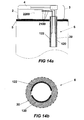
- FIG. 14a and FIG. 14b are schematic diagrams showing side and transverse cross sections, respectively, of electrodes and the penetrating cannula associated with another device for sensing an analyte and dispensing a therapeutic fluid;
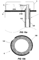
- FIG. 15a and FIG. 15b are schematic diagrams showing a side cross section of a device and an expanded external view of a cannula, respectively, of another possible configuration of the electrodes and the penetrating cannula associated with a device for sensing an analyte and dispensing a therapeutic fluid;
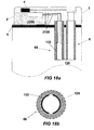
- FIG. 16a and FIG. 16b are schematic diagrams showing a side cross section of a device and an expanded internal view of a cannula, respectively, of another possible configuration of the electrodes and the penetrating cannula associated with a device for sensing an analyte and dispensing a therapeutic fluid;
- FIG. 17a and FIG. 17b are schematic diagrams showing a side cross section and a transverse cross section of a sensing cannula for a device for sensing an analyte and dispensing a therapeutic fluid and including two cannulae;
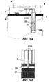
- FIG. 18a and FIG. 18b are schematic diagrams showing a side cross section and a transverse cross section of a sensing cannula for another device for sensing an analyte and dispensing a therapeutic fluid and including two cannulae;
- FIG. 19a and FIG. 19b are schematic diagrams showing side and transverse cross sections, respectively, of electrodes associated with a sensing probe employed in a device for sensing an analyte only;
- FIG. 20a and FIG. 20b are schematic diagrams showing side and transverse cross sections, respectively, of electrodes associated with a sensing probe employed in another device for sensing an analyte only;
- FIG. 21 is a diagram showing possible stages in a process of manufacturing of a sensing probe.
- FIG. 22 is a process flow diagram showing a method for monitoring and controlling the concentration of an analyte in a body.
- the current subject matter includes methods, systems, devices, apparatuses, techniques, and article of manufacture that can be used to provide improved fluid delivery and/or sensing and monitoring of analyte level(s) within a patient's body.
- a closed loop system configured for continuous, real-time monitoring of the analyte concentration levels in the body of a user can be provided. The monitoring can optionally be performed semi-continuously or with any other suitable frequency.
- near normal blood glucose levels can maintained due to delivery of insulin by a pump, such as for example a peristaltic pump, that is controlled in response to continuously, semi-continuously, or periodically monitored glucose levels.
- a pump such as for example a peristaltic pump
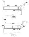
- FIG. 1a and FIG. 1b show two possible implementations of devices 1000 according to the current subject matter.
- the device 1000 can include a patch unit 1010 that can be adhered to a user's skin 5, and a remote control unit 1008.
- the remote control unit 1008 can optionally be a single use device or alternatively be other command means like a multiple purpose computer or communication device such as for example a personal or laptop computer, or a handheld communication device (cell phone, personal data assistant, handheld wireless device, or the like).
- Devices described herein and in accordance with the current subject matter can be capable of operating in one or more of a closed loop, and open loop, or a semi-open loop mode.
- a closed loop mode an analyte concentration is sensed by a sensor and determined by a processor and the processor commands a dispensing apparatus to dispense one or more therapeutic fluids to the human body based on the determined concentration.
- an open loop mode the sensing and dispensing functions are not linked.
- a device in this mode could indicate a value for the determined analyte concentration, but no feedback control is exercised over the rate of dispensing.
- a user interface or other means by which a user can communicate commands to the device can allow the user to dispense the therapeutic fluid.
- the sensing occurs as noted above for the closed loop mode.
- the device can wait for confirmation or alternatively it can request such confirmation, possibly via some user interface, from a user before dispensing the therapeutic fluid in the amounts that might be needed based on the determined analyte concentration.
- a sensing element 2000 can be located subcutaneously, for example mounted on a subcutaneously insertable element, such as for example a cannula 6 that is inserted beneath the surface of the user's skin 5.
- a subcutaneously insertable element such as for example a cannula 6 that is inserted beneath the surface of the user's skin 5.
- cannula the terms “subcutaneously insertable element” and “cannula” will be used interchangeably.
- cannula does not limit the disclosed subject matter only to those subcutaneously insertable elements that fall within the dictionary definition of the word cannula.
- cannula includes both flexible and inflexible tubes that can be inserted into the body to either withdraw one or more body fluids or insert or inject therapeutic fluids including but not limited to medications, hormones, and the like.
- the cannula can be made of a polymer material like Teflon TM .
- Subcutaneously insertable elements or cannulae for the purposes of this disclosure can be of any shape, including but not limited to hollow cylinders of circular or non-circular cross-section.
- a cannula can have one or more distinct passages through which fluid can pass, and these passages can be arranged in any geometric orientation, including but not limited to one or more annular passages, one or more passages or lumens formed by dividing the cross section of the cannula into one or more similar or dissimilar volumes, two or more tubes running parallel through an otherwise non-porous element, or the like.
- the patch unit can include a single part having one housing 1001 as shown in FIG. 1a or may include two parts having two separate housings 1002, 1003 as shown in FIG. 1b .
- FIG. 2 shows additional detail of an implementation of a fluid delivery device 1000.
- the patch unit 1010 in this example includes two parts - a reusable part 2 and a disposable part 3. Each part has its own housing 1002, 1003.
- the device 1000 includes a sensing apparatus 1006 and a dispensing apparatus 1005.
- the relatively inexpensive components such as for example the cannula, 6 and the sensing element 2000 can advantageously be provided in the disposable part 3.
- the relatively more expensive components of both apparatuses, such as for example the electroncs, etc., can be provided in the reusable part 2.
- FIG. 3 shows another possible implementation of a device 1000, in which the dispensing apparatus 1005 and sensing apparatus 1006 are enclosed in a common housing 1001, and share a common single cannula 6 which can be inserted under the skin 5, to within the subcutaneous tissue 50.
- a cannula 6 that is shared between the sensing and dispensing function is referred to herein as dual function cannula.
- a processor-controller apparatus 1007 can also be provided within the housing 1001.
- the processor-controller apparatus 1007 can control dispensing of a fluid, such as for example insulin in accordance with the sensed concentration of an analyte, such as for example glucose.
- the analyte concentration can be obtained via the subcutaneously located sensing element 2000 provided at cannula 6.
- the device 1000 is capable of working as a closed-loop system.
- bidirectional communication between the processor-controller apparatus 1007 and a remote control unit 1008 can allow data acquisition, programming, and user inputs (such as for example meal carbohydrates).
- the device 1000 can also operate as a semi-closed loop system.
- the device 1000 can be attached to the user's skin 5 by adhesives (not shown).
- the dispensing apparatus can alternatively deliver insulin or some other fluid to the body by a separate trans-cutaneous means (not shown) in addition to or instead of a subcutaneous cannula 6.
- An example of such an alternative delivery system includes, but is not limited to, an array of minature needles, which also can provide electrical and ultrasound skin stimulation.
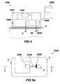
- FIG. 4 shows another implementation of a device 1000 in which a dispensing apparatus 1005 delivers insulin by one cannula 6 and a sensing apparatus 1006 senses glucose by a subcutaneously located sensing element 2000 provided at another cannula 66.
- a processor-controller apparatus 1007 controls insulin delivery by the dispensing apparatus 1005 according to glucose levels sensed by the sensing apparatus 1006 and/or user inputs entered via the remote control unit 1008,
- the two cannulae 6, 66 can be positioned apart from each other a some non-negligible distance.
- FIG. 5a and FIG. 5b show an implementation of the current subject matter in which a device 1000 s configured as a patch unit 1010 that includes two parts -- a reusable part 2 and a disposable part 3.
- FIG. 5a shows a top view of the device 1000
- FIG. 5b shows a side view.
- the device 1000 can include delivery components such as a reservoir 4, a delivery tube 17 and a cannula 6, that are located within the disposable part 3, and a pumping mechanism 7 that is located within the reusable part 2.
- Sensing components can also be provided, for example a subcutaneously locatable sensing element 2000 that is located in the disposable part 3 and electrically connected by electrical wiring 2100 to a sensor processing element 2200 that is located within the reusable part 2.
- FIG. 6a and FIG. 6b show additional details regarding sensing components that can be employed in the fluid delivery device shown in FIG. 5a and FIG. 5b .
- the sensing components can be divided between the two parts of the patch unit 1010.
- Fig.6a depicts the reusable part 2 and the disposable part 3 of the device 1000 connected to one another in an assembled configuration.
- Fig.6b shows the reusable part 2 and the disposable part 3 of the device 1000 disconnected from one another.
- the sensing element 2000 can be located at the cannula 6 situated in the disposable part 3 and the sensor processing element 2200 is located in the reusable part 2.
- the sensor processing element 2200 can also include an amperometric circuit 400. Once the reusable part 2 and the disposable part 3 are connected, the amperometric circuit 400 is electrically closed, as shown in FIG. 6a .
- an amperometer 401, a battery 402, a switch 403, and reusable part contacts 405 can be included in the reusable part 2.
- the disposable part 3 can include the sensing element 2000 which can include two or more electrodes 120,122 that are optionally at least partially covered by or disposed within an insulating layer 21.
- the two or more electrodes 120, 122 can be connected to two disposable part contacts 406 with wiring 2100.
- the electrodes can be located at the cannula 6 of a device 1000 as discussed above and can in some variation reside within a portion of the cannula 6 that protrudes beneath the skin 5 when the device is affixed to the skin or otherwise worn by a user.
- the two or more electrodes can in some variations include a working electrode upon which an electrochemical, optionally enzymatic, reaction occurs, a counter electrode, that can be used to complete a circuit with the fluid with which the sensor is in contact, and optionally a reference electrode, that can be used to determine, by difference or otherwise, a voltage associated with the electrochemical reaction occurring at the working electrode.
- the amperometric circuit 400 When the amperometric circuit 400 is electrically closed by connecting the reusable part 2 and the disposable part 3, electrons flow from the working electrode 122 towards the positive pole of the battery 402.
- the amperometer 401 measures the flowing current.
- the switch 403 can control circuit operation.
- FIG. 7 shows additional detail regarding the sensing element 2000 and disposable part contacts 406.
- the sensing element 2000 can include at least 2 electrodes: one or more working electrodes 122, one or more counter electrodes 120 and optionally a reference electrode.
- the electrodes 120, 122 can be embedded within or otherwise covered by an insulating layer 21 deployed within or near the end of the cannula 6.
- the electrochemical reaction takes place on the working electrode 122 which can be at least partially covered by an analyte sensing layer 23.
- the analyte sensing layer can include the catalytic enzyme, and optionally a mediator and/or any other promoting components that might be desirable to enhance the enzymatic reaction.
- the promoting components can include those currently known in the art for promoting such reactions or other, new compounds or components.
- the analyte sensing layer 23 can in some variations be secured on the working electrode 122 by one or more suitable methods, such as for example cross-linking, entrapment, or the like.
- the counter electrode 120 can be paired with the working electrode 122.
- a reference electrode can in some variations be used for measuring the working electrode potential.
- the generated signal associated with the sensed analyte concentration passes via wiring 2100 between the electrodes 120, 122 of the sensing element 2000 and the disposable part contacts 406.
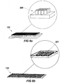
- FIG. 8a and FIG. 8b show possible implementations of the working electrode 122, with surface area enlarging features to enhance the enzyme-analyte interactions.
- the surface area can be enlarged by inclusion of one or more artificially created protrusions 220 as in FIG. 8a and/ or cavities 221 as in FIG. 8b .
- These surface features 220, 221 can be distributed across the surface of the working electrode 122, in some variations the surface distribution can be fractal in nature.
- Similar surface area enlarging features such as for example surface roughness, porosity, or the like can also optionally be used on the counter electrode.
- FIG. 9 shows another implementation of a fluid delivery device 1000 according to the current subject matter.
- the device 1000 is configured as a patch unit 1010, which also incorporates a glucometer or other blood analysis device 90.
- the patch unit 1010 can include a dispensing apparatus and a sensing apparatus, where the sensing apparatus, in addition to its ability to sense the analytes in the interstitial fluid (ISF), also includes the glucometer 90 that allows it to quantify one or more analytes in the blood.
- the glucometer 90 can be located in the reusable part 2 of the patch unit 1010. The user can extract blood from a remote location in the body and place the blood on a test strip 99. The test strip 99 can then be inserted into the glucometer 90 through a dedicated window 95 in the device housing.
- the glucometer (90) can serve as a calibration device contained within the patch unit 1010 of the device 1000.
- a continuous or semi-continuous glucose monitoring system can be calibrated relative to known glucose values determined using the glucometer 90 to maintain accurate glucose measurements throughout device operation.
- a glucometer 90 can be located in the remote control unit 1008 of the fluid delivery device 1000. The glucometer in the remote control 1008 can be used in a similar manner to calibrate the glucose concentrations obtained from the in vivo sensing element 2000 in conjunction with the amperometric circuit 400.
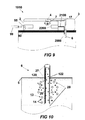
- FIG. 10 shows an example of a cannula 6 that can be used for sensing analyte concentration levels and for delivering fluid (dual function cannula).
- the cannula 6 has upper 27 and lower 28 portions that can be positioned, respectively, above and below the surface of the skin 5.
- the cannula 6 can be fitted with internal sensing electrodes 120, 122.
- the lower cannula portion 28 can include a semi-permeable membrane 29 that allows substances having low molecular weights, and particularly, of the desired analyte (such as for example glucose) 13 to pass through pores of the semi-permeable membrane 29, while molecules of substances 14 having of higher molecular weights are tend to not pass through the pores of the membrane 29.
- the desired analyte such as for example glucose
- the cannula 6 can be perfused with an analyte-fiee solution (such as for example insulin or saline) to facilitate diffusion of analyte across the semi-permeable membrane 29 from the tissue fluid (such as for example the ISF) to the interior of the cannula 6.
- analyte-fiee solution such as for example insulin or saline
- the diffusion process occurs in the direction of the concentration gradient, between the tissue fluid (ISF) and the solution within the cannula 6, until a partial or full analyte concentration equilibrium, or a "recovery" state, is established.
- Analyte concentration levels can be electrochemically measured using at least one working electrode 122 and at least one counter electrode 120 located within the subcutaneous cannula portion 28.
- FIG. 11 shows another example of a dual function cannula 6 that has a membrane 30 having large pores that allow analyte diffusion across the membrane 30, such that the desired analyte (such as for example glucose) 13 and substances 14 of higher molecular weight pass through the larger pores.
- a cannula 6 allows fast analyte diffusion rate and shorter times for establishing the "recovery" state.
- Analyte concentration levels can be electrochemically measured using at least one working electrode 122 and at least one counter electrode 120 located within the subcutaneous cannula portion 28.
- FIG. 12a and FIG. 12b show examples of cannulas 6 having a double lumen construction.
- the cannula 6 can include a sensing compartment or passage 60 and a dispensing compartment, passage, or lumen 70 that do not communicate with each other.
- the compartments or lumens can be separated by a wall.
- Monitoring analyte (e.g. glucose) levels can be carried out through the sensing compartment, passage, or lumen 60 which communicates with one or more sensing components as discussed above.
- the dispensing of fluid e.g. insulin
- Figures 13-18 show several exemplary variations of a patch unit 1010 that can contain both sensing and dispensing components, with various configurations of subcutaneously insertable electrodes.
- the insertable electrodes can include at least one working electrode, at least one counter electrode and optionally an additional reference electrode.
- Components of the patch unit or external device 1000 in these implementations can include a reusable part 2 with a sensing processing element 2200, and a disposable part 3 with a reservoir 4, cannula 6, and delivery tube 17.
- a reusable part 2 with a sensing processing element 2200 and a disposable part 3 with a reservoir 4, cannula 6, and delivery tube 17.
- FIG. 13a and FIG. 13b show longitudinal and transverse cross sectional views, respectively of a cannula 6 with the electrodes 120, 122 extending along the entire length of the cannula 6.
- the electrodes 120, 122 might extend only along a portion of the length of the cannula in a longitudinal direction or parallel with the longitudinal axis.
- the electrodes 120 and 122 can be formed as two or more electrically isolated sections of the outer walls of the cannula 6 and can include a working electrode, a counter electrode, and optionally a reference electrode such as for example as discussed above.
- FIG. 14a and FIG. 14b show longitudinal and transverse cross sectional views, respectively, of a cannula 6 with the electrodes 120, 122 extending along the entire length of the cannula or along a region thereof.
- the counter and working electrodes 120, 122 are not positioned externally to the cannula as in the example of FIG. 13a and FIG. 13b . Rather, in FIG. 14a and FIG. 14b , the electrodes 120, 122 are positioned on electrically isolated internal surfaces of the cannula 6.
- the walls of the cannula 6 can be formed of a semi-permeable or permeable material that thus allows diffusion of the desired analyte into the interior of the cannula 6.
- the interior of the cannula 6 can function as a measurement cell.
- FIG. 15a and FIG. 15b show a longitudinal cross sectional view and a zoomed in outer surface view, respectively, of another example of a cannula 6 having electrodes 120, 122 located on the outer surface of the cannula 6.
- the electrodes 120, 122 can be disposed on the outer surface of the cannula 6.
- One electrode 120 can be disposed nearer the distal end of the cannula and electrically isolated, for example by an insulating material that could be used to form the structure of the cannula 6 itself.
- the second electrode 122 can be formed as a band that at least partly encircles the circumferential axis of the cannula 6.
- Wiring 2100 connects the electrodes 120, 122 to the sensor processing element 2200, which can be located in the reusable part 2 of the patch unit 1010 as discussed above.
- FIG. 16a and FIG. 16b show a longitudinal cross sectional view and a zoomed in inner surface view, respectively, of another example of a cannula 6 having working 122 and counter 120 electrodes located on the inner surface of the cannula 6.
- the walls of the cannula can be semi-permeable or permeable to allow analytes to enter the measurement cell formed within the cannula 6.
- FIG. 17 and 18 show examples of patch units 1010 that include two cannulae 6, 66.
- a first cannula 6 can be used for sensing the analyte and a second cannula 66 can be used for dispensing therapeutic fluid.
- FIG. 17a and FIG. 18a show longitudinal views of the two implementations
- FIG. 17b and FIG. 18b show cross sectional views of the two implementations.
- the electrodes are disposed on the outer surface of the cannula 6 and oriented along at least part of the longitudinal axis of the cannula 6.
- the electrodes 120, 122 are disposed on the inner surface of a cannula 6 whose walls can be semi-permeable or permeable over at least some area of the wall.
- FIG. 19a and FIG. 19b show longitudinal and transverse cross sectional views, respectively, of the working 122 and counter 120 electrodes extending along the entire or partial length (not shown) of the outer surface of the cannula 6.
- FIG. 20a and FIG. 20b show longitudinal and transverse cross sectional views, respectively, of the four electrodes 120,122 extending along the entire or partial length (not shown) of the inner surface of the cannula 6.
- the cannula 6 walls can be semi-permeable or permeable along all or part of the surface area of the cannula that penetrates the skin 5.
- FIG. 21 illustrates a possible process for fabrication of electrodes on the outer or inner surface of a cannula 6.
- This process can include formation of two grooves 40 on the cannula 6 surface, such as for example as shown in Fig. 21a .
- the grooves can be filled with conductive material 41 as shown in FIG. 21b .
- Electrodes can alternatively be deposited on the external surface of the cannula 6 by vapor deposition, sputtering, painting, printing, replication, electro-less deposition, or any other method now known or hereafter developed. Electrodes can be deposited on inner surfaces of the cannula 6 by sputtering, painting, replication, electro less deposition, or any other method now known or hereafter developed. One of the electrodes can be temporarily covered.
- the counter electrode can be covered with a removable protective layer 42 as shown in Fig. 21c .
- the protective layer 42 can be any adherable material that is not penetrable. All of the electrodes can then be covered with electrochemical reagents 43 (such as for example an enzyme, a mediator, or the like) as shown in FIG. 21d .
- the protective layer 42 can be pealed from the counter electrode as shown in FIG. 21e .
- the working electrodes can be formed.
- the working electrode can be loaded or otherwise coated with one or more electrochemical reagents while the counter electrodes are free of the electrochemical reagents. After pealing the protective layer from the counter electrode, only the working electrode carries electrochemical reagents.
- FIG. 22 is a process flow chart 3000 that shows stages of a method for sensing and controlling blood glucose levels using a closed loop device.
- a patch unit that includes a processor and a subcutaneously insertable element can optionally be adhered or secured to a skin area of the human body such that a distal end of the subcutaneously insertable element is positioned beneath the skin surface and in contact with interstitial fluid of human body.
- the adhering or securing can optionally be by means of an adhesive, by suction, by one or more hooks that grasp a portion of the skin surface, or the like.
- the proximal end of the subcutaneously insertable element can be part of or mechanically connected to the patch unit or other mechanical device.
- the concentration of an analyte within the human body can be electrochemically detected using a sensor that is secured to or otherwise associated with the distal end of the subcutaneously insertable element.
- This electrochemical detection can optionally be accomplished by generating a signal that represents the concentration at the sensor, possibly by means of an enzymatic reaction as discussed above.
- the signal can optionally be received and processed at a processor in the external device or patch unit.
- therapeutic fluid can be dispensed to the human body at 3006.
- Dispensing of the therapeutic fluid can optionally include delivering a command from the processor to a dispensing apparatus in the external device.
- the dispensing apparatus can be one of those as described above or other similar structures.
- the command can cause the dispensing apparatus to dispense an amount of the therapeutic fluid sufficient to alter the concentration of the analyte in the human body so that the concentration returns to within the target range.
Abstract
a first subcutaneously insertable element with a distal portion (28) for subcutaneous placement within a human body, the subcutaneous insertable element comprising a cannula (66) with first and second electrodes (120,122) disposed on an inner or outer surface thereof;
a sensor (2000) that electrochemically interacts with one or more analytes and generates a signal that is representative of a concentration of the one or more analytes, the sensor being disposed on or within the distal portion (28) of the first subcutaneously insertable element; and
an external device (1001), (1002, 1003) in mechanical contact with a proximal portion (27) of the first subcutaneously insertable element, the external device comprising:
a processor (1007) that receives and processes the signal from the sensor (2000) to determine the concentration of the one or more analytes within the human body; and
a delivery subsystem for delivering a therapeutic fluid via a second subcutaneously insertable element.
Description
- This application claims the benefit of
U.S. Provisional Patent Application Serial No. 60/876,945, filed on December 22, 2006 - The subject matter described herein relates to delivery of a fluid via a device or other mechanisms that is also capable of in vivo sensing of one or more analytes.
- Diabetes mellitus is a disease of major global importance, and its fiequency of incidence has been increasing at almost epidemic rates. The worldwide prevalence in 2006 was 170 million people, and this number is predicted to at least double over the next 10-15 years. Diabetes is generally characterized by a chronically raised blood glucose concentration (hyperglycemia), due to a relative or absolute lack of the pancreatic hormone, insulin. In a normal (non-diabetic) subject, pancreatic islet cells (beta cells) continuously sense the blood glucose levels and consequently regulate insulin secretion to maintain near constant levels. However, diabetic patients lack this capability.
- Much of the burden of the disease to the patient and to health care resources is due to long-term tissue complications, which can affect both the small blood vessels (microangiopathy, causing eye, kidney and nerve damage) and the large blood vessels (causing accelerated atherosclerosis, with increased rates of coronary heart disease, peripheral vascular disease and stroke). There is now evidence that morbidity and mortality of diabetic patients is related to the duration and severity of hyperglycemia. In theory, maintaining normal blood glucose levels by hormone replacement therapy using insulin injections and/or other treatments in diabetes might be able to prevent complications. However, near-normal blood glucose levels can be quite difficult to achieve and maintain in many patients, particularly in those having Type 1 diabetes. In these patients, blood glucose concentrations can vary fairly quickly between very high (hyperglycemia) and very low (hypoglycemia) levels in an unpredictable manner.
- Many diabetic patients currently measure their own blood glucose several times during the day by using finger-prick capillary samples and applying the blood to a reagent strip for analysis in a portable glucose meter. The discomfort involved with these tests can often lead to poor patient compliance. Testing cannot be performed while sleeping and while the subject is occupied. In addition, the readings do not give information regarding the trends in glucose levels, but rather provide only discrete readings, taken at large time intervals between the measurements. Therefore continuous glucose monitoring-would-be advantageous, providing essentially continuous glucose readings by performing discrete measurements, at a very high frequency.
- An electrochemical glucose sensor is described in
U.S. Patent No. 6,612,111 assigned to Lifescan Inc., which is hereby incorporated by reference herein. Today, the majority of available electrochemical glucose sensors are enzyme-based. The detection principle of these sensors is based on the monitoring of the enzyme-catalysed oxidation of glucose. These include glucose sensors use amperometric or potentiometric operating principles. - The enzymatic reaction that occurs in the majority of these sensors is catalyzed by glucose oxidase (GOX). During this reaction, oxygen and glucose yield gluconic acid and hydrogen peroxide. Glucose oxidase acts temporarily as an electron acceptor, where it is first reduced to an inactive state and subsequently is reactivated by the reduction of oxygen to hydrogen peroxide. The glucose concentration is transformed into a detectable signal, which is proportional to the glucose level and which is generally measured by amperometric methods.
- An enzyme-coated working electrode can serve as the sensor transducer, which is where electrochemical oxidation or reduction takes place. A counter electrode can be paired with the working electrode. A current of opposite sign passes through the two electrodes. The intensity of the current is a function of the concentration of electro-active glucose. An increased surface area between the analyte sensing layer (containing the enzyme) and the working electrode can enable enzyme loading, which is necessary for overcoming degradation of the enzyme as the reaction proceeds. The increased surface area can also enable enhanced electron transfer between the enzyme active site and the sensor transducer, thus improving the sensor performance.
- Several ambulatory insulin infusion devices are currently available on the market. The first generation disposable devices configured as syringe-type reservoir are described in
1972, by Hobbs, in U.S. Patent No. 2,631,847 , and in1973, by Kaminski, in U.S. Patent No. 3,771,694 , and later byJulius, in U.S. Patent No. 4,657,486 , and bySkakoon, US Patent No. 4,544,369 , each of which is hereby incorporated by reference herein. These devices are generally quite large and heavy due to their spatial design and the relatively large driving mechanism of the syringe and the piston. This relatively bulky device has to be carried in a patient's pocket or attached to the belt. Consequently, the fluid delivery tube can be quite long, in some cases grater than 40 cm, to permit needle insertion in remote sites of the body. Such uncomfortable, bulky fluid delivery devices can be rejected by many diabetic insulin users, because of their negative impact on the performance of regular activities, such as for example sleeping and swinuning. Furthermore, some more self-conscious users, such as for example teenagers, are likely to reject the use of such a device because of the potential negative body image that might result from using it. In addition, the long delivery tube can exclude some potential remote insertion sites, such as for example the buttocks and the extremities. - To avoid potential disadvantages associated with tubing, a second generation of pumps based on a new concept has been devised. These pumps can include a housing having a bottom surface adapted for attaching to the user's skin, a reservoir disposed within the housing, and an injection needle in fluid communication with the reservoir. These skin adherable devices are generally disposed of every 2-3 days similarly to the infusion sets employed in the pumps of the first generation. Devices of this type have been described by
Schneider, in US Patent No. 4498843 ,Burton in U.S. Patent No. 5,957,895 ,Connelly, in U.S. Patent No. 6,589,229 , and byFlaherty in U.S. Patent No. 6,740,059 , each of which is incorporated by reference herein. Other configurations of skin adherable pumps are disclosed inU.S. Patent Nos. 6,723,072 and6,485,461 , which are also incorporated by reference herein. The pumps described in these references are generally designed as a single piece and remain adhered to the user's skin for the entire usage duration. The needle emerges from the bottom surface of the device and is fixed to the device housing. - Another fluid delivery device is described in international patent application no.
PCT/IL06/001276 - In one aspect of the current subject matter, an apparatus includes a subcutaneously insertable element that includes a proximal portion and a distal portion. The distal portion is configured for subcutaneous placement within a human body. The apparatus also includes a sensor that electrochemically interacts with one or more analytes and generates a signal that is representative of a concentration of the one or more analytes. The sensor is disposed on or within the distal portion of the subcutaneously insertable element. A processor receives and processes the signal from the sensor to determine the concentration of the one or more analytes within the human body. An external device includes the processor and is in mechanical contact with the proximal portion of the subcutaneously insertable element.
- Optional variations of the current subject matter can include one or more af the following features. The subcutaneously insertable element can optionally include a cannula having an internal volume and a wall surface. The cannula can optionally include a first electrode and a second electrode that is electrically isolated from the first electrode. The first electrode and the second electrode can optionally be secured to the cannula. The first electrode and the second electrode can optionally be disposed on an outer surface of the cannula. The wall surface of the cannula can optionally include a permeable or semi-permeable material that permits at least the one or more analytes to diffuse into the internal volume. The first electrode and the second electrode can optionally be disposed on an inner surface of the cannula. One or more of the first and second electrodes can optionally be disposed along at least part of a circumferential axis of the cannula or alternatively, along at least part of a longitudinal axis of the cannula. When the subcutaneously insertable element is placed subcutaneously, the sensor can optionally contact interstitial fluid. The sensor can optionally include a first electrode that has a first exposed surface that is at least partially coated with an electrochemical reagent and a second electrode that has a second exposed surface that is substantially free of the electrochemical reagent. The electrochemical reagent can optionally include an enzymatic assay that undergoes a chemical reaction with the one or more analytes, the chemical reaction producing a measurable voltage or current differential between the first electrode and the second electrode. The first and/or the second exposed surface can optionally include one or more surface area enlarging features.
- The apparatus can optionally further include a reservoir that contains a fluid and a pump that flushes the subcutaneously insertable element with the fluid from the reservoir. The pump can optionally include a peristaltic pump or alternatively a syringe pump. The external device can optionally include a disposable part and a reusable part. The disposable part can optionally include the subcutaneously insertable element and the reusable part can optionally include the processor. The external device can optionally further include a delivery subsystem for a therapeutic fluid. The dispensing apparatus can optionally be controlled by the processor to deliver the therapeutic fluid in response to the concentration of the one or more analytes determined by the processor. The therapeutic fluid can optionally include insulin. The therapeutic fluid can optionally be delivered via the subcutaneously insertable element. The subcutaneously insertable element can optionally include a first lumen that comprises the sensor at the distal end of the subcutaneously insertable element and a second lumen through which the therapeutic fluid is delivered. Alternatively, the therapeutic fluid can optionally be delivered via a second subcutaneously insertable element. The processor can optionally automatically control the dispensing apparatus based on the determined concentration or, alternatively, the external device can provide an alert to a user to request that the user activate the dispensing apparatus based on the determined concentration. The sensor can optionally measure the concentration of the one or more analytes with a fiequency that is either continuous, semi-continuous, periodic, or discrete.
- The external device can also optionally further include a blood analysis device connected to the processor and a port via which a blood sample from the body is delivered to the blood analysis device. The blood analysis device can analyze the blood sample to independently determine the concentration of the one or more analytes and provide a calibration data point for the sensor. The blood analysis device can optionally include a glucometer. The one or more analytes can optionally include glucose. The external device can optionally include an adherable or securable surface that adheres or secures the device to the human body. The processor can optionally receive one or more commands from a remote control unit.
- In an interrelated aspect, a method for fabrication of electrodes of a sensor on a surface of subcutaneously insertable element includes forming grooves on the surface of the subcutaneously insertable element, depositing conductive material within the grooves, temporarily covering at least one of the grooves to prevent contamination of the conductive material, depositing an electrochemical reagent on the uncovered position of the grooves, and removing the covering from the at least one of the grooves.
- In another interrelated aspect, a method includes electrochemically detecting, with a sensor secured to a distal end of a subcutaneously insertable element, a concentration of an analyte within a human body, and based on the detecting, dispensing a therapeutic fluid to the human body.
- In optional variations, one or more of the following features can be included. A device that comprises a processor and the subcutaneously insertable element can optionally be adhered or secured to a skin area of the human body such that the distal end of the subcutaneously insertable element is positioned beneath the skin surface and in contact with interstitial fluid of the human body. The electrochemical detection can optionally include generating a signal at the sensor that is representative of the concentration, and receiving and processing the signal at a processor in an external device that is mechanically connected to a proximal end of the subcutaneously insertable element. The dispensing of the therapeutic fluid can optionally include delivering a command from the processor to a dispensing apparatus in the external device. The command can optionally cause the dispensing apparatus to dispense an amount of the therapeutic fluid based on the determined concentration of the analyte in the human body. The dispensing of the therapeutic fluid optionally occurs via the subcutaneously insertable element. Alternatively, the dispensing of the therapeutic fluid optionally occurs via a second subcutaneously insertable element. Such devices can be closed loop, meaning that dispensing and sensing occur automatically or open loop or semi-open loop in which some user interaction is required before dispensing occurs.
- The subject matter described herein can, in some implementations, provide one or more of the following advantages. For example, glycemic control can be achieved using a device or method that performs two important functions of a normal pancreas, namely glucose monitoring and insulin delivery. A closed loop system having a feedback mechanism combining both functions (often referred to as an "artificial pancreas") can be used to maintain near normal blood glucose levels in patients suffering from diabetes.
- The details of one or more variations of the subject matter described herein are set forth in the accompanying drawings and the description below. Other features and advantages of the subject matter described herein will be apparent from the description and drawings, and from the claims.
- The accompanying drawings, which are incorporated in and constitute a part of this specification, show certain aspects of the subject matter disclosed herein and, together with the description, help explain some of the principles associated with the disclosed embodiments. In the drawings,
-
FIG. 1a and FIG. 1b are schematic diagrams showing examples of a fluid delivery device configured as a patch unit and a remote control unit; -
FIG. 2 is a schematic diagram showing an example of a fluid delivery device configured as a patch unit fitted with reusable and disposable parts residing in separate housings; -
FIG. 3 is a schematic diagram showing an example of a closed loop system fitted with a single cannula and including a dispensing apparatus, and a sensing apparatus; -
FIG. 4 is a schematic diagram showing an example of a closed loop system that includes a dispensing apparatus, a sensing apparatus, the processor-controller apparatus, and the remote control unit, in which the dispensing and sensing apparatuses have separate cannulae; -
FIG. 5a andFIG. 5b are schematic diagrams showing a bottom view and a side cross-sectional view, respectively, of a fluid delivery device that includes a reusable part and a disposable part, with electrochemical sensing components deployed in these parts; -
FIG. 6a andFIG. 6b are schematic diagrams showing a possible distribution of sensing apparatus components within the disposable and reusable parts of a device; -
FIG. 7 is a schematic diagram showing additional detail of an example of a sensing element; -
FIG. 8a and FIG. 8b are isometric diagrams showing examples of how the surface area of a working electrode can be increased; -
FIG. 9 is a schematic diagram showing a glucometer that uses a blood glucose test strip incorporated into an example device; -
FIG. 10 is a schematic diagram showing an example of a semi-permeable cannula and the diffusion process; -
FIG. 11 is a schematic diagram showing an example of a permeable cannula and the diffusion process; -
FIG. 12a and FIG. 12b are schematic diagrams showing double lumen cannulae; -
FIG. 13a and FIG. 13b are schematic diagrams showing side and transverse cross sections, respectively, of electrodes and the penetrating cannula associated with an example device for sensing an analyte and dispensing a therapeutic fluid; - -
FIG. 14a and FIG. 14b are schematic diagrams showing side and transverse cross sections, respectively, of electrodes and the penetrating cannula associated with another device for sensing an analyte and dispensing a therapeutic fluid; -
FIG. 15a and FIG. 15b are schematic diagrams showing a side cross section of a device and an expanded external view of a cannula, respectively, of another possible configuration of the electrodes and the penetrating cannula associated with a device for sensing an analyte and dispensing a therapeutic fluid; -
FIG. 16a and FIG. 16b are schematic diagrams showing a side cross section of a device and an expanded internal view of a cannula, respectively, of another possible configuration of the electrodes and the penetrating cannula associated with a device for sensing an analyte and dispensing a therapeutic fluid; -
FIG. 17a and FIG. 17b are schematic diagrams showing a side cross section and a transverse cross section of a sensing cannula for a device for sensing an analyte and dispensing a therapeutic fluid and including two cannulae; -
FIG. 18a and FIG. 18b are schematic diagrams showing a side cross section and a transverse cross section of a sensing cannula for another device for sensing an analyte and dispensing a therapeutic fluid and including two cannulae; -
FIG. 19a and FIG. 19b are schematic diagrams showing side and transverse cross sections, respectively, of electrodes associated with a sensing probe employed in a device for sensing an analyte only; -
FIG. 20a and FIG. 20b are schematic diagrams showing side and transverse cross sections, respectively, of electrodes associated with a sensing probe employed in another device for sensing an analyte only; -
FIG. 21 is a diagram showing possible stages in a process of manufacturing of a sensing probe; and -
FIG. 22 is a process flow diagram showing a method for monitoring and controlling the concentration of an analyte in a body. - The current subject matter includes methods, systems, devices, apparatuses, techniques, and article of manufacture that can be used to provide improved fluid delivery and/or sensing and monitoring of analyte level(s) within a patient's body. A closed loop system configured for continuous, real-time monitoring of the analyte concentration levels in the body of a user can be provided. The monitoring can optionally be performed semi-continuously or with any other suitable frequency. In a closed loop system, near normal blood glucose levels can maintained due to delivery of insulin by a pump, such as for example a peristaltic pump, that is controlled in response to continuously, semi-continuously, or periodically monitored glucose levels. In this manner, an "artificial pancreas" can be provided to assist diabetic patients in living more normal lives.
- Currently available closed loop systems are generally composed of two separate devices -- a sensor and a pump -- which can be expensive, bulky and heavy and are typically separately attached to the user's belt or skin. In addition, each of the two devices can require its own infusion set with long tubing and accordingly two insertion sites on the patient's body. It can be appreciated that the use of such a device could increase insertion and disconnection times and could produce undesirable effects like infections, irritations, bleeding, etc. As such, a need exists for an improved fluid delivery and/or sensing devices for delivering fluid to and/or monitoring analyte level(s) within a patient's body which is free of the above-mentioned drawbacks.
-
FIG. 1a and FIG. 1b show two possible implementations ofdevices 1000 according to the current subject matter. Thedevice 1000 can include apatch unit 1010 that can be adhered to a user'sskin 5, and aremote control unit 1008. Theremote control unit 1008 can optionally be a single use device or alternatively be other command means like a multiple purpose computer or communication device such as for example a personal or laptop computer, or a handheld communication device (cell phone, personal data assistant, handheld wireless device, or the like). - Devices described herein and in accordance with the current subject matter can be capable of operating in one or more of a closed loop, and open loop, or a semi-open loop mode. In a closed loop mode, an analyte concentration is sensed by a sensor and determined by a processor and the processor commands a dispensing apparatus to dispense one or more therapeutic fluids to the human body based on the determined concentration. In an open loop mode, the sensing and dispensing functions are not linked. A device in this mode could indicate a value for the determined analyte concentration, but no feedback control is exercised over the rate of dispensing. A user interface or other means by which a user can communicate commands to the device can allow the user to dispense the therapeutic fluid. In the semi-closed mode, the sensing occurs as noted above for the closed loop mode. However, the device can wait for confirmation or alternatively it can request such confirmation, possibly via some user interface, from a user before dispensing the therapeutic fluid in the amounts that might be needed based on the determined analyte concentration.
- A
sensing element 2000 can be located subcutaneously, for example mounted on a subcutaneously insertable element, such as for example acannula 6 that is inserted beneath the surface of the user'sskin 5. For purposes of this disclosure, the terms "subcutaneously insertable element" and "cannula" will be used interchangeably. However, it will be understood that the term "cannula" does not limit the disclosed subject matter only to those subcutaneously insertable elements that fall within the dictionary definition of the word cannula. For example, in this disclosure, cannula includes both flexible and inflexible tubes that can be inserted into the body to either withdraw one or more body fluids or insert or inject therapeutic fluids including but not limited to medications, hormones, and the like. As for example, the cannula can be made of a polymer material like Teflon™. Subcutaneously insertable elements or cannulae for the purposes of this disclosure can be of any shape, including but not limited to hollow cylinders of circular or non-circular cross-section. A cannula can have one or more distinct passages through which fluid can pass, and these passages can be arranged in any geometric orientation, including but not limited to one or more annular passages, one or more passages or lumens formed by dividing the cross section of the cannula into one or more similar or dissimilar volumes, two or more tubes running parallel through an otherwise non-porous element, or the like. - Various aspects of such subcutaneously insertable elements according to various implementations of the current subject matter are discussed in greater detail below. The patch unit can include a single part having one
housing 1001 as shown inFIG. 1a or may include two parts having twoseparate housings FIG. 1b . -
FIG. 2 shows additional detail of an implementation of afluid delivery device 1000. Thepatch unit 1010 in this example includes two parts - areusable part 2 and adisposable part 3. Each part has itsown housing device 1000 includes asensing apparatus 1006 and adispensing apparatus 1005. The relatively inexpensive components, such as for example the cannula, 6 and thesensing element 2000 can advantageously be provided in thedisposable part 3. The relatively more expensive components of both apparatuses, such as for example the electroncs, etc., can be provided in thereusable part 2. -
FIG. 3 shows another possible implementation of adevice 1000, in which thedispensing apparatus 1005 andsensing apparatus 1006 are enclosed in acommon housing 1001, and share a commonsingle cannula 6 which can be inserted under theskin 5, to within thesubcutaneous tissue 50. Acannula 6 that is shared between the sensing and dispensing function is referred to herein as dual function cannula. A processor-controller apparatus 1007 can also be provided within thehousing 1001. The processor-controller apparatus 1007 can control dispensing of a fluid, such as for example insulin in accordance with the sensed concentration of an analyte, such as for example glucose. The analyte concentration can be obtained via the subcutaneously locatedsensing element 2000 provided atcannula 6. Thedevice 1000 is capable of working as a closed-loop system. In another implementation, bidirectional communication between the processor-controller apparatus 1007 and aremote control unit 1008 can allow data acquisition, programming, and user inputs (such as for example meal carbohydrates). In this implementation, thedevice 1000 can also operate as a semi-closed loop system. Thedevice 1000 can be attached to the user'sskin 5 by adhesives (not shown). The dispensing apparatus can alternatively deliver insulin or some other fluid to the body by a separate trans-cutaneous means (not shown) in addition to or instead of asubcutaneous cannula 6. An example of such an alternative delivery system includes, but is not limited to, an array of minature needles, which also can provide electrical and ultrasound skin stimulation. -
FIG. 4 shows another implementation of adevice 1000 in which adispensing apparatus 1005 delivers insulin by onecannula 6 and asensing apparatus 1006 senses glucose by a subcutaneously locatedsensing element 2000 provided at anothercannula 66. A processor-controller apparatus 1007 controls insulin delivery by thedispensing apparatus 1005 according to glucose levels sensed by thesensing apparatus 1006 and/or user inputs entered via theremote control unit 1008, In one variation, the twocannulae -
FIG. 5a andFIG. 5b show an implementation of the current subject matter in which a device 1000 s configured as apatch unit 1010 that includes two parts -- areusable part 2 and adisposable part 3.FIG. 5a shows a top view of thedevice 1000 andFIG. 5b shows a side view. Thedevice 1000 can include delivery components such as areservoir 4, adelivery tube 17 and acannula 6, that are located within thedisposable part 3, and apumping mechanism 7 that is located within thereusable part 2. Sensing components can also be provided, for example a subcutaneouslylocatable sensing element 2000 that is located in thedisposable part 3 and electrically connected byelectrical wiring 2100 to asensor processing element 2200 that is located within thereusable part 2. -
FIG. 6a andFIG. 6b show additional details regarding sensing components that can be employed in the fluid delivery device shown inFIG. 5a andFIG. 5b . The sensing components can be divided between the two parts of thepatch unit 1010.Fig.6a depicts thereusable part 2 and thedisposable part 3 of thedevice 1000 connected to one another in an assembled configuration.Fig.6b shows thereusable part 2 and thedisposable part 3 of thedevice 1000 disconnected from one another. Thesensing element 2000 can be located at thecannula 6 situated in thedisposable part 3 and thesensor processing element 2200 is located in thereusable part 2. Thesensor processing element 2200 can also include anamperometric circuit 400. Once thereusable part 2 and thedisposable part 3 are connected, theamperometric circuit 400 is electrically closed, as shown inFIG. 6a . - As shown in
FIG. 6b , anamperometer 401, abattery 402, aswitch 403, andreusable part contacts 405 can be included in thereusable part 2. Thedisposable part 3 can include thesensing element 2000 which can include two or more electrodes 120,122 that are optionally at least partially covered by or disposed within an insulatinglayer 21. The two ormore electrodes disposable part contacts 406 withwiring 2100. The electrodes can be located at thecannula 6 of adevice 1000 as discussed above and can in some variation reside within a portion of thecannula 6 that protrudes beneath theskin 5 when the device is affixed to the skin or otherwise worn by a user. The two or more electrodes can in some variations include a working electrode upon which an electrochemical, optionally enzymatic, reaction occurs, a counter electrode, that can be used to complete a circuit with the fluid with which the sensor is in contact, and optionally a reference electrode, that can be used to determine, by difference or otherwise, a voltage associated with the electrochemical reaction occurring at the working electrode. - When the
amperometric circuit 400 is electrically closed by connecting thereusable part 2 and thedisposable part 3, electrons flow from the workingelectrode 122 towards the positive pole of thebattery 402. Theamperometer 401 measures the flowing current. Theswitch 403 can control circuit operation. -
FIG. 7 shows additional detail regarding thesensing element 2000 anddisposable part contacts 406. Thesensing element 2000 can include at least 2 electrodes: one or more workingelectrodes 122, one ormore counter electrodes 120 and optionally a reference electrode. Theelectrodes layer 21 deployed within or near the end of thecannula 6. The electrochemical reaction takes place on the workingelectrode 122 which can be at least partially covered by ananalyte sensing layer 23. The analyte sensing layer can include the catalytic enzyme, and optionally a mediator and/or any other promoting components that might be desirable to enhance the enzymatic reaction. The promoting components can include those currently known in the art for promoting such reactions or other, new compounds or components. Theanalyte sensing layer 23 can in some variations be secured on the workingelectrode 122 by one or more suitable methods, such as for example cross-linking, entrapment, or the like. As noted above, thecounter electrode 120 can be paired with the workingelectrode 122. A reference electrode can in some variations be used for measuring the working electrode potential. The generated signal associated with the sensed analyte concentration passes viawiring 2100 between theelectrodes sensing element 2000 and thedisposable part contacts 406. -
FIG. 8a and FIG. 8b show possible implementations of the workingelectrode 122, with surface area enlarging features to enhance the enzyme-analyte interactions. The surface area can be enlarged by inclusion of one or more artificially createdprotrusions 220 as inFIG. 8a and/ orcavities 221 as inFIG. 8b . These surface features 220, 221 can be distributed across the surface of the workingelectrode 122, in some variations the surface distribution can be fractal in nature. Similar surface area enlarging features, such as for example surface roughness, porosity, or the like can also optionally be used on the counter electrode. -
FIG. 9 shows another implementation of afluid delivery device 1000 according to the current subject matter. InFIG. 9 , thedevice 1000 is configured as apatch unit 1010, which also incorporates a glucometer or otherblood analysis device 90. Thepatch unit 1010 can include a dispensing apparatus and a sensing apparatus, where the sensing apparatus, in addition to its ability to sense the analytes in the interstitial fluid (ISF), also includes theglucometer 90 that allows it to quantify one or more analytes in the blood. Theglucometer 90 can be located in thereusable part 2 of thepatch unit 1010. The user can extract blood from a remote location in the body and place the blood on atest strip 99. Thetest strip 99 can then be inserted into theglucometer 90 through adedicated window 95 in the device housing. - In some variations, the glucometer (90) can serve as a calibration device contained within the
patch unit 1010 of thedevice 1000. A continuous or semi-continuous glucose monitoring system can be calibrated relative to known glucose values determined using theglucometer 90 to maintain accurate glucose measurements throughout device operation. Alternatively or in addition aglucometer 90 can be located in theremote control unit 1008 of thefluid delivery device 1000. The glucometer in theremote control 1008 can be used in a similar manner to calibrate the glucose concentrations obtained from the invivo sensing element 2000 in conjunction with theamperometric circuit 400. -
FIG. 10 shows an example of acannula 6 that can be used for sensing analyte concentration levels and for delivering fluid (dual function cannula). Thecannula 6 has upper 27 and lower 28 portions that can be positioned, respectively, above and below the surface of theskin 5. Thecannula 6 can be fitted withinternal sensing electrodes lower cannula portion 28 can include a semi-permeable membrane 29 that allows substances having low molecular weights, and particularly, of the desired analyte (such as for example glucose) 13 to pass through pores of the semi-permeable membrane 29, while molecules ofsubstances 14 having of higher molecular weights are tend to not pass through the pores of the membrane 29. Thecannula 6 can be perfused with an analyte-fiee solution (such as for example insulin or saline) to facilitate diffusion of analyte across the semi-permeable membrane 29 from the tissue fluid (such as for example the ISF) to the interior of thecannula 6. The diffusion process occurs in the direction of the concentration gradient, between the tissue fluid (ISF) and the solution within thecannula 6, until a partial or full analyte concentration equilibrium, or a "recovery" state, is established. Analyte concentration levels can be electrochemically measured using at least one workingelectrode 122 and at least onecounter electrode 120 located within thesubcutaneous cannula portion 28. -
FIG. 11 shows another example of adual function cannula 6 that has amembrane 30 having large pores that allow analyte diffusion across themembrane 30, such that the desired analyte (such as for example glucose) 13 andsubstances 14 of higher molecular weight pass through the larger pores. Such acannula 6 allows fast analyte diffusion rate and shorter times for establishing the "recovery" state. Analyte concentration levels can be electrochemically measured using at least one workingelectrode 122 and at least onecounter electrode 120 located within thesubcutaneous cannula portion 28. -
FIG. 12a and FIG. 12b show examples ofcannulas 6 having a double lumen construction. Thecannula 6 can include a sensing compartment orpassage 60 and a dispensing compartment, passage, orlumen 70 that do not communicate with each other. The compartments or lumens can be separated by a wall. Monitoring analyte (e.g. glucose) levels can be carried out through the sensing compartment, passage, orlumen 60 which communicates with one or more sensing components as discussed above. The dispensing of fluid (e.g. insulin) can be carried out through the dispensing compartment, passage, orlumen 70 which communicates with one or more dispensing components as discussed above. -
Figures 13-18 show several exemplary variations of apatch unit 1010 that can contain both sensing and dispensing components, with various configurations of subcutaneously insertable electrodes. In general, the insertable electrodes can include at least one working electrode, at least one counter electrode and optionally an additional reference electrode. - Components of the patch unit or
external device 1000 in these implementations can include areusable part 2 with asensing processing element 2200, and adisposable part 3 with areservoir 4,cannula 6, anddelivery tube 17. On the outside surface of the cannula there can be two ormore electrodes sensing processing element 2200. -
FIG. 13a and FIG. 13b show longitudinal and transverse cross sectional views, respectively of acannula 6 with theelectrodes cannula 6. In some variations, theelectrodes FIG. 13a and FIG. 13b , theelectrodes cannula 6 and can include a working electrode, a counter electrode, and optionally a reference electrode such as for example as discussed above. -
FIG. 14a and FIG. 14b show longitudinal and transverse cross sectional views, respectively, of acannula 6 with theelectrodes electrodes FIG. 13a and FIG. 13b . Rather, inFIG. 14a and FIG. 14b , theelectrodes cannula 6. The walls of thecannula 6 can be formed of a semi-permeable or permeable material that thus allows diffusion of the desired analyte into the interior of thecannula 6. The interior of thecannula 6 can function as a measurement cell. -
FIG. 15a and FIG. 15b show a longitudinal cross sectional view and a zoomed in outer surface view, respectively, of another example of acannula 6 havingelectrodes cannula 6. In this example, theelectrodes cannula 6. Oneelectrode 120 can be disposed nearer the distal end of the cannula and electrically isolated, for example by an insulating material that could be used to form the structure of thecannula 6 itself. Thesecond electrode 122 can be formed as a band that at least partly encircles the circumferential axis of thecannula 6.Wiring 2100 connects theelectrodes sensor processing element 2200, which can be located in thereusable part 2 of thepatch unit 1010 as discussed above. -
FIG. 16a and FIG. 16b show a longitudinal cross sectional view and a zoomed in inner surface view, respectively, of another example of acannula 6 having working 122 and counter 120 electrodes located on the inner surface of thecannula 6. The walls of the cannula can be semi-permeable or permeable to allow analytes to enter the measurement cell formed within thecannula 6. -
Figures 17 and18 show examples ofpatch units 1010 that include twocannulae first cannula 6 can be used for sensing the analyte and asecond cannula 66 can be used for dispensing therapeutic fluid.FIG. 17a andFIG. 18a show longitudinal views of the two implementations, andFIG. 17b andFIG. 18b show cross sectional views of the two implementations. InFIG. 17 , the electrodes are disposed on the outer surface of thecannula 6 and oriented along at least part of the longitudinal axis of thecannula 6. InFIG. 18 theelectrodes cannula 6 whose walls can be semi-permeable or permeable over at least some area of the wall. -
Figures 19 and20 show examples ofpatch units 1010 that include only a sensing apparatus (stand-alone sensor). These devices can be used for sensing of in vivo analyte concentrations.FIG. 19a and FIG. 19b show longitudinal and transverse cross sectional views, respectively, of the working 122 and counter 120 electrodes extending along the entire or partial length (not shown) of the outer surface of thecannula 6.FIG. 20a and FIG. 20b show longitudinal and transverse cross sectional views, respectively, of the four electrodes 120,122 extending along the entire or partial length (not shown) of the inner surface of thecannula 6. Thecannula 6 walls can be semi-permeable or permeable along all or part of the surface area of the cannula that penetrates theskin 5. -
FIG. 21 illustrates a possible process for fabrication of electrodes on the outer or inner surface of acannula 6. This process can include formation of twogrooves 40 on thecannula 6 surface, such as for example as shown inFig. 21a . The grooves can be filled withconductive material 41 as shown inFIG. 21b . Electrodes can alternatively be deposited on the external surface of thecannula 6 by vapor deposition, sputtering, painting, printing, replication, electro-less deposition, or any other method now known or hereafter developed. Electrodes can be deposited on inner surfaces of thecannula 6 by sputtering, painting, replication, electro less deposition, or any other method now known or hereafter developed. One of the electrodes can be temporarily covered. For example the counter electrode can be covered with a removableprotective layer 42 as shown inFig. 21c . Theprotective layer 42 can be any adherable material that is not penetrable. All of the electrodes can then be covered with electrochemical reagents 43 (such as for example an enzyme, a mediator, or the like) as shown inFIG. 21d . Theprotective layer 42 can be pealed from the counter electrode as shown inFIG. 21e . At the end of the fabrication process, the working electrodes can be formed. The working electrode can be loaded or otherwise coated with one or more electrochemical reagents while the counter electrodes are free of the electrochemical reagents. After pealing the protective layer from the counter electrode, only the working electrode carries electrochemical reagents. -
FIG. 22 is aprocess flow chart 3000 that shows stages of a method for sensing and controlling blood glucose levels using a closed loop device. At 3002, a patch unit that includes a processor and a subcutaneously insertable element can optionally be adhered or secured to a skin area of the human body such that a distal end of the subcutaneously insertable element is positioned beneath the skin surface and in contact with interstitial fluid of human body. The adhering or securing can optionally be by means of an adhesive, by suction, by one or more hooks that grasp a portion of the skin surface, or the like. As described above, the proximal end of the subcutaneously insertable element can be part of or mechanically connected to the patch unit or other mechanical device. At 3004, the concentration of an analyte within the human body can be electrochemically detected using a sensor that is secured to or otherwise associated with the distal end of the subcutaneously insertable element. This electrochemical detection can optionally be accomplished by generating a signal that represents the concentration at the sensor, possibly by means of an enzymatic reaction as discussed above. The signal can optionally be received and processed at a processor in the external device or patch unit. If the concentration is determined to be outside of a target concentration range, therapeutic fluid can be dispensed to the human body at 3006. Dispensing of the therapeutic fluid can optionally include delivering a command from the processor to a dispensing apparatus in the external device. The dispensing apparatus can be one of those as described above or other similar structures. The command can cause the dispensing apparatus to dispense an amount of the therapeutic fluid sufficient to alter the concentration of the analyte in the human body so that the concentration returns to within the target range. - The implementations set forth in the foregoing description do not represent all implementations consistent with the subject matter described herein. Instead, they are merely some examples consistent with aspects related to the described subject matter. Other aspects, advantages, and modifications are considered to be within the scope of the claims presented below. The claims presented are representative of the subject matter disclosed herein. Other, unclaimed aspects of the disclosed subject matter are also contemplated.
- Wherever possible, the same reference numbers have been used throughout the drawings to refer to the same or like parts. Although a few variations have been described in detail above, other modifications or additions are possible. In particular, further features and/or variations may be provided in addition to those set forth herein. For example, the implementations described above may be directed to various combinations and subcombinations of the disclosed features and/or combinations and subcombinations of several further features disclosed above. In addition, the logic flow depicted in the accompanying figures and/or described herein does not require the particular order shown, or sequential order, to achieve desirable results. Other embodiments may be within the scope of the following claims.
Claims (14)
- An apparatus (1000) comprising:a first subcutaneously insertable element that comprises a proximal portion (27) and a distal portion (28), the distal portion (28) being configured for subcutaneous placement within a human body, the subcutaneous insertable element comprising a cannula (66) having an internal volume and a wall surface, the cannula (66) comprising a first electrode (120) and a second electrode (122) electrically isolated from the first electrode (120), the first electrode (120) and the second electrode (122) being disposed on an inner or outer surface of the cannula (66);a sensor (2000) that electrochemically interacts with one or more analytes and generates a signal that is representative of a concentration of the one or more analytes, the sensor being disposed on or within the distal portion (28) of the first subcutaneously insertable element; andan external device (1001), (1002, 1003) in mechanical contact with the proximal portion (27) of the first subcutaneously insertable element, the external device comprising:a processor (1007) that receives and processes the signal from the sensor (2000) to determine the concentration of the one or more analytes within the human body; anda delivery subsystem for delivering a therapeutic fluid via a second subcutaneously insertable element.
- The apparatus (1000) of claim 1, wherein at least part of the wall surface of the cannula (66) is permeable or semi-permeable.
- The apparatus (1000) of claim 1 or claim 2, wherein one or more of the first and second electrodes (120, 122) is disposed along at least part of a circumferential axis of the cannula (66).
- The apparatus (1000) of claim 1 or claim 2, wherein one or more of the first and second electrodes (120,122) is disposed along at least part of a longitudinal axis of the cannula (66).
- The apparatus (1000) of any of claims 1-4, wherein the first electrode (120) comprises a first exposed surface that is at least partially coated with an electrochemical reagent and the second electrode (122) comprises a second exposed surface that is substantially free of the electrochemical reagent.
- The apparatus (1000) of claim 5, wherein the first and/or the second exposed surface comprise one or more surface area enlarging features (220, 221).
- The apparatus (1000) of any of claims 1-6, wherein the external device comprises a disposable part (3) and a reusable part (2), the disposable part (3) comprising the cannula (66) and the reusable part comprising the processor (1007).
- The apparatus (1000) of any of claims 1-7, wherein delivery subsystem comprises a dispensing apparatus (1005) adapted to be controlled by the processor (1007) to deliver the therapeutic fluid based on the concentration of the one or more analytes determined by the processor (1007).
- The apparatus (1000) of any of claims 1-8, wherein the external device further comprises a blood analysis device (90) connected to the processor (1007) and a port via which a blood sample from the body is delivered to the blood analysis device, the blood analysis device (90) analyzing the blood sample to independently determine the concentration of the one or more analytes.
- The apparatus (1000) of any of claims 1-9, wherein the apparatus is capable of operating in one or more of a closed loop mode, an open loop mode, and a semi-open loop mode.
- The apparatus (1000) of any of claims 1-10, wherein the therapeutic fluid comprises insulin and the one or more analytes comprises glucose.
- The apparatus (1000) of any of claims 1-11, wherein the external device comprises means for securing or adhering the external device to the human body.
- The apparatus (1000) of any of claims 1-12, wherein the first and second electrodes (120,122) are deposited on the inner or outer surface of the cannula (66).
- The apparatus (1000) of any of claims 1-13, wherein each of the first and second electrodes (120,122) comprises conductive material deposited in a groove formed on the inner or outer surface of the cannula (66), with one of the first and second electrodes (120,122) being coated with an electrochemical reagent.
Applications Claiming Priority (2)
| Application Number | Priority Date | Filing Date | Title |
|---|---|---|---|
| US87694506P | 2006-12-22 | 2006-12-22 | |
| EP07849605A EP2124726A1 (en) | 2006-12-22 | 2007-12-20 | Fluid delivery with in vivo electrochemical analyte sensing |
Related Parent Applications (1)
| Application Number | Title | Priority Date | Filing Date |
|---|---|---|---|
| EP07849605.6 Division | 2007-12-20 |
Publications (1)
| Publication Number | Publication Date |
|---|---|
| EP2601883A1 true EP2601883A1 (en) | 2013-06-12 |
Family
ID=39247973
Family Applications (2)
| Application Number | Title | Priority Date | Filing Date |
|---|---|---|---|
| EP07849605A Withdrawn EP2124726A1 (en) | 2006-12-22 | 2007-12-20 | Fluid delivery with in vivo electrochemical analyte sensing |
| EP13158027.6A Withdrawn EP2601883A1 (en) | 2006-12-22 | 2007-12-20 | Fluid delivery with in vivo electrochemical analyte sensing |
Family Applications Before (1)
| Application Number | Title | Priority Date | Filing Date |
|---|---|---|---|
| EP07849605A Withdrawn EP2124726A1 (en) | 2006-12-22 | 2007-12-20 | Fluid delivery with in vivo electrochemical analyte sensing |
Country Status (6)
| Country | Link |
|---|---|
| US (1) | US9028409B2 (en) |
| EP (2) | EP2124726A1 (en) |
| JP (1) | JP5624322B2 (en) |
| CN (2) | CN101563022B (en) |
| AU (1) | AU2007337685A1 (en) |
| WO (1) | WO2008078319A1 (en) |
Cited By (1)
| Publication number | Priority date | Publication date | Assignee | Title |
|---|---|---|---|---|
| EP3278728A1 (en) * | 2016-08-01 | 2018-02-07 | Nokia Technologies Oy | An apparatus, system and method for detecting analytes from a user's skin |
Families Citing this family (57)
| Publication number | Priority date | Publication date | Assignee | Title |
|---|---|---|---|---|
| US20190357827A1 (en) | 2003-08-01 | 2019-11-28 | Dexcom, Inc. | Analyte sensor |
| EP2121076B1 (en) * | 2006-12-29 | 2017-04-05 | F. Hoffmann-La Roche AG | Infusion device that can be worn outside the body |
| US8679062B2 (en) * | 2007-04-10 | 2014-03-25 | Roche Diagnostics Operations Inc. | Apparatus and method for pumping fluid |
| EP1987761B1 (en) * | 2007-05-03 | 2019-10-23 | F. Hoffmann-La Roche AG | Tube-like sensor for proving an analyte |
| US8002752B2 (en) | 2007-06-25 | 2011-08-23 | Medingo, Ltd. | Protector apparatus |
| EP2173408A1 (en) * | 2007-06-27 | 2010-04-14 | Medingo Ltd. | Tubing for fluid delivery device |
| WO2009004627A2 (en) * | 2007-07-02 | 2009-01-08 | Medingo Ltd. | A device for drug delivery |
| EP4098177A1 (en) | 2007-10-09 | 2022-12-07 | DexCom, Inc. | Integrated insulin delivery system with continuous glucose sensor |
| AU2008327483A1 (en) * | 2007-11-21 | 2009-05-28 | Medingo Ltd. | Analyte monitoring and fluid dispensing system |
| WO2009081403A2 (en) * | 2007-12-26 | 2009-07-02 | Medingo Ltd. | Maintaining glycemic control during exercise |
| EP2230991B1 (en) * | 2007-12-26 | 2018-07-04 | Roche Diabetes Care GmbH | System for glycemic control |
| US8845613B2 (en) | 2008-01-28 | 2014-09-30 | Roche Diagnostics Operations, Inc. | Bolus dose determination for a therapeutic fluid dispensing system |
| EP2300077B1 (en) | 2008-04-09 | 2017-07-19 | Roche Diabetes Care GmbH | Modular skin-adherable system for medical fluid delivery |
| WO2009133557A2 (en) * | 2008-04-29 | 2009-11-05 | Medingo Ltd. | Methods and apparatuses for selecting a bolus delivery pattern in a drug delivery device |
| US8480649B2 (en) | 2008-04-29 | 2013-07-09 | Ofer Yodfat | Method for selecting bolus doses and bolus delivery patterns in a drug delivery device |
| EP2286361A2 (en) * | 2008-05-16 | 2011-02-23 | Medingo Ltd. | Device and method for alleviating postprandial hyperglycemia |
| ES2787230T3 (en) * | 2008-05-29 | 2020-10-15 | Hoffmann La Roche | Modular medical infusion device with means for identification / authentication between its components |
| US8632497B2 (en) * | 2008-10-09 | 2014-01-21 | Roche Diagnostics Operations Inc. | Skin securable drug delivery device with a shock absorbing protective shield |
| WO2010044088A1 (en) | 2008-10-16 | 2010-04-22 | Medingo Ltd. | Method and system for adaptive communication transmission |
| EP2379133A1 (en) | 2008-11-11 | 2011-10-26 | Medingo Ltd. | Modular fluid delivery device with quick-release /connect mechanism for drive screw |
| EP2391408B1 (en) | 2008-12-31 | 2018-01-17 | Roche Diabetes Care GmbH | Portable medical fluid delivery device with drive screw articulated with reservoir plunger |
| WO2010092572A1 (en) | 2009-02-13 | 2010-08-19 | Medingo Ltd. | Insulin delivery safety |
| AU2010255324A1 (en) | 2009-06-04 | 2012-01-19 | F.Hoffmann-La Roche Ag | Device and method for adjusting basal delivery profile |
| EP2442843A4 (en) | 2009-06-14 | 2012-11-28 | Medingo Ltd | Devices and methods for malfunctions recognition in a therapeutic dispensing device |
| EP2445407B1 (en) | 2009-06-25 | 2015-02-18 | Roche Diagnostics GmbH | A method and device for improving glycemic control based on residual insulin |
| US8437827B2 (en) * | 2009-06-30 | 2013-05-07 | Abbott Diabetes Care Inc. | Extruded analyte sensors and methods of using same |
| US20100326842A1 (en) * | 2009-06-30 | 2010-12-30 | Abbott Diabetes Care Inc. | Extruded Electrode Structures and Methods of Using Same |
| US10369281B2 (en) | 2009-09-08 | 2019-08-06 | Roche Diagnostics Operations, Inc. | Devices, systems and methods for adjusting fluid delivery parameters |
| CN102630159A (en) | 2009-09-18 | 2012-08-08 | 梅丁格有限公司 | Devices, systems and methods for quantifying bolus doses according to user parameters |
| EP2506914B1 (en) | 2009-11-30 | 2018-10-17 | Roche Diabetes Care GmbH | Analyte monitoring and fluid dispensing system |
| WO2011089600A1 (en) | 2010-01-20 | 2011-07-28 | Medingo Ltd. | A method and device for improving glycemic control |
| MX2012012567A (en) | 2010-04-28 | 2012-11-21 | Kimberly Clark Co | Method for increasing permeability of an epithelial barrier. |
| JP5871907B2 (en) * | 2010-04-28 | 2016-03-01 | キンバリー クラーク ワールドワイド インコーポレイテッド | Nanopatterned medical device with enhanced cell-cell interaction |
| EP2563451B1 (en) | 2010-04-28 | 2017-11-01 | Kimberly-Clark Worldwide, Inc. | MEDICAL DEVICES FOR DELIVERY OF siRNA |
| WO2011135530A2 (en) | 2010-04-28 | 2011-11-03 | Kimberly-Clark Worldwide, Inc. | Device for delivery of rheumatoid arthritis medication |
| CN107961016B (en) * | 2010-12-09 | 2021-06-15 | 雅培糖尿病护理股份有限公司 | Analyte sensor having a sensing surface comprising a small sensing spot |
| US20170246439A9 (en) | 2011-10-27 | 2017-08-31 | Kimberly-Clark Worldwide, Inc. | Increased Bioavailability of Transdermally Delivered Agents |
| EP3542851B1 (en) | 2011-10-27 | 2021-12-15 | Sorrento Therapeutics, Inc. | Implantable devices for delivery of bioactive agents |
| WO2013061208A1 (en) | 2011-10-27 | 2013-05-02 | Kimberly-Clark Worldwide, Inc. | Transdermal delivery of high viscosity bioactive agents |
| US9931065B2 (en) * | 2012-04-04 | 2018-04-03 | Dexcom, Inc. | Transcutaneous analyte sensors, applicators therefor, and associated methods |
| EP2674179A1 (en) * | 2012-06-15 | 2013-12-18 | Ares Trading S.A. | Injection device |
| EP2674184A1 (en) | 2012-06-15 | 2013-12-18 | Ares Trading S.A. | Injection device with needle sensor |
| WO2015008169A2 (en) * | 2013-07-04 | 2015-01-22 | Insuline Medical Ltd. | Device, system and method for delivery of a long-acting drug |
| KR102290278B1 (en) | 2014-08-12 | 2021-08-17 | 삼성전자주식회사 | Noninvasive apparatus for testing liver function and noninvasive method for testing liver function |
| CN113855009A (en) | 2015-12-30 | 2021-12-31 | 德克斯康公司 | Transdermal analyte sensor systems and methods |
| KR101868015B1 (en) * | 2016-05-17 | 2018-06-15 | 주식회사 아이센스 | Device of Auto-Supplying Insulin and Diabetic Management System Using the Same |
| JP2018063203A (en) * | 2016-10-14 | 2018-04-19 | ソニーセミコンダクタソリューションズ株式会社 | Potential detection substrate and potential measuring device |
| EP3925522A1 (en) | 2017-06-23 | 2021-12-22 | Dexcom, Inc. | Transcutaneous analyte sensors, applicators therefor, and associated methods |
| US11331022B2 (en) | 2017-10-24 | 2022-05-17 | Dexcom, Inc. | Pre-connected analyte sensors |
| AU2018354120A1 (en) | 2017-10-24 | 2020-04-23 | Dexcom, Inc. | Pre-connected analyte sensors |
| CN112237658B (en) * | 2019-07-19 | 2022-10-04 | 上海移宇科技股份有限公司 | Integrated drug infusion device |
| CN112237661B (en) * | 2019-07-19 | 2022-10-11 | 上海移宇科技股份有限公司 | Infusion detects unilateral drive medical device in an organic whole |
| WO2021012075A1 (en) * | 2019-07-19 | 2021-01-28 | Medtrum Technologies Inc. | Integrated drug infusion device |
| US11523757B2 (en) * | 2019-08-01 | 2022-12-13 | Medtronic Minimed, Inc. | Micro-pillar working electrodes design to reduce backflow of hydrogen peroxide in glucose sensor |
| EP4017357A4 (en) * | 2019-08-19 | 2023-04-19 | Medtrum Technologies Inc. | Sensing device |
| EP4274637A1 (en) * | 2021-01-05 | 2023-11-15 | Medtrum Technologies Inc. | Skin patch drug infusion device |
| WO2023168284A1 (en) * | 2022-03-01 | 2023-09-07 | Insulet Corporation | Single package automated drug delivery system |
Citations (17)
| Publication number | Priority date | Publication date | Assignee | Title |
|---|---|---|---|---|
| US2631847A (en) | 1949-04-19 | 1953-03-17 | Armstrong Cork Co | Web accumulator |
| US3771694A (en) | 1972-07-07 | 1973-11-13 | A Kaminski | Infusion pump |
| US4498843A (en) | 1982-08-02 | 1985-02-12 | Schneider Philip H | Insulin infusion pump |
| US4544369A (en) | 1983-11-22 | 1985-10-01 | C. R. Bard, Inc. | Battery operated miniature syringe infusion pump |
| US4657486A (en) | 1984-01-13 | 1987-04-14 | Stempfle Julius E | Portable infusion device |
| US5390671A (en) * | 1994-03-15 | 1995-02-21 | Minimed Inc. | Transcutaneous sensor insertion set |
| US5957895A (en) | 1998-02-20 | 1999-09-28 | Becton Dickinson And Company | Low-profile automatic injection device with self-emptying reservoir |
| US6275717B1 (en) * | 1997-06-16 | 2001-08-14 | Elan Corporation, Plc | Device and method of calibrating and testing a sensor for in vivo measurement of an analyte |
| WO2001058348A2 (en) * | 2000-02-10 | 2001-08-16 | Minimed Inc. | Improved analyte sensor and method of making the same |
| EP1153571A1 (en) * | 2000-05-08 | 2001-11-14 | A. Menarini Industrie Farmaceutiche Riunite S.R.L. | Apparatus for measurement and control of the content of glucose, lactate or other metabolites in biological fluids |
| US6485461B1 (en) | 2000-04-04 | 2002-11-26 | Insulet, Inc. | Disposable infusion device |
| US6589229B1 (en) | 2000-07-31 | 2003-07-08 | Becton, Dickinson And Company | Wearable, self-contained drug infusion device |
| US6612111B1 (en) | 2000-03-27 | 2003-09-02 | Lifescan, Inc. | Method and device for sampling and analyzing interstitial fluid and whole blood samples |
| US6723072B2 (en) | 2002-06-06 | 2004-04-20 | Insulet Corporation | Plunger assembly for patient infusion device |
| US6740059B2 (en) | 2000-09-08 | 2004-05-25 | Insulet Corporation | Devices, systems and methods for patient infusion |
| US20060001550A1 (en) * | 1998-10-08 | 2006-01-05 | Mann Alfred E | Telemetered characteristic monitor system and method of using the same |
| US20060263839A1 (en) * | 2005-05-17 | 2006-11-23 | Isense Corporation | Combined drug delivery and analyte sensor apparatus |
Family Cites Families (28)
| Publication number | Priority date | Publication date | Assignee | Title |
|---|---|---|---|---|
| US3631847A (en) * | 1966-03-04 | 1972-01-04 | James C Hobbs | Method and apparatus for injecting fluid into the vascular system |
| US4403984A (en) * | 1979-12-28 | 1983-09-13 | Biotek, Inc. | System for demand-based adminstration of insulin |
| US4449843A (en) * | 1981-11-30 | 1984-05-22 | Space Structures International Corp. | Octa hub |
| US4671288A (en) * | 1985-06-13 | 1987-06-09 | The Regents Of The University Of California | Electrochemical cell sensor for continuous short-term use in tissues and blood |
| US4685463A (en) * | 1986-04-03 | 1987-08-11 | Williams R Bruce | Device for continuous in vivo measurement of blood glucose concentrations |
| AT391998B (en) * | 1987-02-02 | 1990-12-27 | Falko Dr Skrabal | Device for determining the concentration of at least one medicinal substance in living organisms |
| IE72524B1 (en) | 1994-11-04 | 1997-04-23 | Elan Med Tech | Analyte-controlled liquid delivery device and analyte monitor |
| EP0868144B1 (en) * | 1995-12-19 | 2005-01-26 | Abbott Laboratories | Device for the detection of analyte and administration of a therapeutic substance |
| US7267665B2 (en) * | 1999-06-03 | 2007-09-11 | Medtronic Minimed, Inc. | Closed loop system for controlling insulin infusion |
| US6033866A (en) * | 1997-12-08 | 2000-03-07 | Biomedix, Inc. | Highly sensitive amperometric bi-mediator-based glucose biosensor |
| US5993423A (en) * | 1998-08-18 | 1999-11-30 | Choi; Soo Bong | Portable automatic syringe device and injection needle unit thereof |
| US6254586B1 (en) * | 1998-09-25 | 2001-07-03 | Minimed Inc. | Method and kit for supplying a fluid to a subcutaneous placement site |
| WO2002039086A2 (en) * | 2000-11-13 | 2002-05-16 | Nipro Diabetes Systems | Glucose sensor system |
| CN1185493C (en) * | 2001-11-16 | 2005-01-19 | 清华大学 | Intelligent microdestructive blood sugar tester measuring method and devcie |
| WO2003090614A1 (en) * | 2002-04-25 | 2003-11-06 | Matsushita Electric Industrial Co., Ltd. | Dosage determination supporting device, injector, and health management supporting system |
| US20040010207A1 (en) * | 2002-07-15 | 2004-01-15 | Flaherty J. Christopher | Self-contained, automatic transcutaneous physiologic sensing system |
| US7713574B2 (en) * | 2004-07-13 | 2010-05-11 | Dexcom, Inc. | Transcutaneous analyte sensor |
| US7547281B2 (en) * | 2005-02-01 | 2009-06-16 | Medtronic Minimed, Inc. | Algorithm sensor augmented bolus estimator for semi-closed loop infusion system |
| WO2006087708A2 (en) * | 2005-02-17 | 2006-08-24 | Medingo Ltd. | Method and apparatus for monitoring bodily analytes |
| CN101180093B (en) * | 2005-03-21 | 2012-07-18 | 雅培糖尿病护理公司 | Method and system for providing integrated medication infusion and analyte monitoring system |
| US8105280B2 (en) * | 2005-05-17 | 2012-01-31 | Medingo, Ltd. | Disposable dispenser for patient infusion |
| US7935104B2 (en) * | 2005-11-07 | 2011-05-03 | Medingo, Ltd. | Systems and methods for sustained medical infusion and devices related thereto |
| EP1993637A2 (en) * | 2006-02-15 | 2008-11-26 | Medingo Ltd. | Systems and methods for sensing analyte and dispensing therapeutic fluid |
| US9119582B2 (en) * | 2006-06-30 | 2015-09-01 | Abbott Diabetes Care, Inc. | Integrated analyte sensor and infusion device and methods therefor |
| US8435211B2 (en) * | 2006-07-24 | 2013-05-07 | Medingo Ltd. | Systems, devices and methods for fluid/drug delivery |
| DK2083673T3 (en) * | 2006-09-29 | 2012-09-24 | Medingo Ltd | FLUID DISTRIBUTION SYSTEM WITH ELECTROCHEMICAL DETECTION OF ANALYTIC CONCENTRATION LEVELS |
| EP2099384B1 (en) * | 2006-11-28 | 2018-09-05 | Roche Diabetes Care GmbH | An insertion device and method for inserting a subcutaneously insertable element into a body |
| CN101573151A (en) * | 2006-12-22 | 2009-11-04 | 梅丁格有限公司 | Systems and devices for sustained delivery of a therapeutic fluid |
-
2007
- 2007-12-20 CN CN200780046642.3A patent/CN101563022B/en not_active Expired - Fee Related
- 2007-12-20 JP JP2009542394A patent/JP5624322B2/en not_active Expired - Fee Related
- 2007-12-20 EP EP07849605A patent/EP2124726A1/en not_active Withdrawn
- 2007-12-20 EP EP13158027.6A patent/EP2601883A1/en not_active Withdrawn
- 2007-12-20 CN CN201210150258.0A patent/CN102743179B/en not_active Expired - Fee Related
- 2007-12-20 AU AU2007337685A patent/AU2007337685A1/en not_active Abandoned
- 2007-12-20 WO PCT/IL2007/001579 patent/WO2008078319A1/en active Application Filing
- 2007-12-21 US US11/963,481 patent/US9028409B2/en not_active Expired - Fee Related
Patent Citations (17)
| Publication number | Priority date | Publication date | Assignee | Title |
|---|---|---|---|---|
| US2631847A (en) | 1949-04-19 | 1953-03-17 | Armstrong Cork Co | Web accumulator |
| US3771694A (en) | 1972-07-07 | 1973-11-13 | A Kaminski | Infusion pump |
| US4498843A (en) | 1982-08-02 | 1985-02-12 | Schneider Philip H | Insulin infusion pump |
| US4544369A (en) | 1983-11-22 | 1985-10-01 | C. R. Bard, Inc. | Battery operated miniature syringe infusion pump |
| US4657486A (en) | 1984-01-13 | 1987-04-14 | Stempfle Julius E | Portable infusion device |
| US5390671A (en) * | 1994-03-15 | 1995-02-21 | Minimed Inc. | Transcutaneous sensor insertion set |
| US6275717B1 (en) * | 1997-06-16 | 2001-08-14 | Elan Corporation, Plc | Device and method of calibrating and testing a sensor for in vivo measurement of an analyte |
| US5957895A (en) | 1998-02-20 | 1999-09-28 | Becton Dickinson And Company | Low-profile automatic injection device with self-emptying reservoir |
| US20060001550A1 (en) * | 1998-10-08 | 2006-01-05 | Mann Alfred E | Telemetered characteristic monitor system and method of using the same |
| WO2001058348A2 (en) * | 2000-02-10 | 2001-08-16 | Minimed Inc. | Improved analyte sensor and method of making the same |
| US6612111B1 (en) | 2000-03-27 | 2003-09-02 | Lifescan, Inc. | Method and device for sampling and analyzing interstitial fluid and whole blood samples |
| US6485461B1 (en) | 2000-04-04 | 2002-11-26 | Insulet, Inc. | Disposable infusion device |
| EP1153571A1 (en) * | 2000-05-08 | 2001-11-14 | A. Menarini Industrie Farmaceutiche Riunite S.R.L. | Apparatus for measurement and control of the content of glucose, lactate or other metabolites in biological fluids |
| US6589229B1 (en) | 2000-07-31 | 2003-07-08 | Becton, Dickinson And Company | Wearable, self-contained drug infusion device |
| US6740059B2 (en) | 2000-09-08 | 2004-05-25 | Insulet Corporation | Devices, systems and methods for patient infusion |
| US6723072B2 (en) | 2002-06-06 | 2004-04-20 | Insulet Corporation | Plunger assembly for patient infusion device |
| US20060263839A1 (en) * | 2005-05-17 | 2006-11-23 | Isense Corporation | Combined drug delivery and analyte sensor apparatus |
Cited By (1)
| Publication number | Priority date | Publication date | Assignee | Title |
|---|---|---|---|---|
| EP3278728A1 (en) * | 2016-08-01 | 2018-02-07 | Nokia Technologies Oy | An apparatus, system and method for detecting analytes from a user's skin |
Also Published As
| Publication number | Publication date |
|---|---|
| JP2011507556A (en) | 2011-03-10 |
| CN102743179B (en) | 2016-03-16 |
| CN101563022B (en) | 2012-05-30 |
| JP5624322B2 (en) | 2014-11-12 |
| WO2008078319A1 (en) | 2008-07-03 |
| CN101563022A (en) | 2009-10-21 |
| US9028409B2 (en) | 2015-05-12 |
| CN102743179A (en) | 2012-10-24 |
| AU2007337685A1 (en) | 2008-07-03 |
| US20080214916A1 (en) | 2008-09-04 |
| EP2124726A1 (en) | 2009-12-02 |
Similar Documents
| Publication | Publication Date | Title |
|---|---|---|
| US9028409B2 (en) | Fluid delivery with in vivo electrochemical analyte sensing | |
| US20240033429A1 (en) | Integrated analyte sensor and infusion device and methods therefo | |
| JP2011507556A5 (en) | ||
| US8814822B2 (en) | Reciprocating delivery of fluids to the body with analyte concentration monitoring | |
| US10258737B2 (en) | Analyte monitoring and fluid dispensing system | |
| US9248232B2 (en) | Analyte monitoring and fluid dispensing system | |
| US9056161B2 (en) | Fluid delivery system with electrochemical sensing of analyte concentration levels | |
| KR100945901B1 (en) | A minimally-invasive system and method for monitoring analyte levels | |
| US20090312622A1 (en) | Device And Method For Determining A Value Of A Physiological Parameter Of A Body Fluid | |
| EP1993637A2 (en) | Systems and methods for sensing analyte and dispensing therapeutic fluid |
Legal Events
| Date | Code | Title | Description |
|---|---|---|---|
| PUAI | Public reference made under article 153(3) epc to a published international application that has entered the european phase |
Free format text: ORIGINAL CODE: 0009012 |
|
| AC | Divisional application: reference to earlier application |
Ref document number: 2124726 Country of ref document: EP Kind code of ref document: P |
|
| AK | Designated contracting states |
Kind code of ref document: A1 Designated state(s): AT BE BG CH CY CZ DE DK EE ES FI FR GB GR HU IE IS IT LI LT LU LV MC MT NL PL PT RO SE SI SK TR |
|
| RIN1 | Information on inventor provided before grant (corrected) |
Inventor name: IDDAN, GAVRIEL J. Inventor name: SHAPIRA, GALI Inventor name: KAIDAR, RUTHY Inventor name: YODFAT, OFER |
|
| RIN1 | Information on inventor provided before grant (corrected) |
Inventor name: KAIDAR, RUTHY Inventor name: IDDAN, GAVRIEL J. Inventor name: YODFAT, OFER Inventor name: SHAPIRA, GALI |
|
| 17P | Request for examination filed |
Effective date: 20131105 |
|
| RBV | Designated contracting states (corrected) |
Designated state(s): AT BE BG CH CY CZ DE DK EE ES FI FR GB GR HU IE IS IT LI LT LU LV MC MT NL PL PT RO SE SI SK TR |
|
| RAP1 | Party data changed (applicant data changed or rights of an application transferred) |
Owner name: F.HOFFMANN-LA ROCHE AG Owner name: ROCHE DIAGNOSTICS GMBH |
|
| GRAP | Despatch of communication of intention to grant a patent |
Free format text: ORIGINAL CODE: EPIDOSNIGR1 |
|
| RIC1 | Information provided on ipc code assigned before grant |
Ipc: A61B 5/00 20060101AFI20160422BHEP |
|
| INTG | Intention to grant announced |
Effective date: 20160512 |
|
| RAP1 | Party data changed (applicant data changed or rights of an application transferred) |
Owner name: ROCHE DIABETES CARE GMBH Owner name: F.HOFFMANN-LA ROCHE AG |
|
| STAA | Information on the status of an ep patent application or granted ep patent |
Free format text: STATUS: THE APPLICATION IS DEEMED TO BE WITHDRAWN |
|
| 18D | Application deemed to be withdrawn |
Effective date: 20160923 |