EP2520320B1 - Catheter system - Google Patents
Catheter system Download PDFInfo
- Publication number
- EP2520320B1 EP2520320B1 EP12178965.5A EP12178965A EP2520320B1 EP 2520320 B1 EP2520320 B1 EP 2520320B1 EP 12178965 A EP12178965 A EP 12178965A EP 2520320 B1 EP2520320 B1 EP 2520320B1
- Authority
- EP
- European Patent Office
- Prior art keywords
- catheter
- introducer
- sheath
- stent
- catheter system
- Prior art date
- Legal status (The legal status is an assumption and is not a legal conclusion. Google has not performed a legal analysis and makes no representation as to the accuracy of the status listed.)
- Active
Links
Images


Classifications
-
- A—HUMAN NECESSITIES
- A61—MEDICAL OR VETERINARY SCIENCE; HYGIENE
- A61M—DEVICES FOR INTRODUCING MEDIA INTO, OR ONTO, THE BODY; DEVICES FOR TRANSDUCING BODY MEDIA OR FOR TAKING MEDIA FROM THE BODY; DEVICES FOR PRODUCING OR ENDING SLEEP OR STUPOR
- A61M25/00—Catheters; Hollow probes
- A61M25/01—Introducing, guiding, advancing, emplacing or holding catheters
- A61M25/06—Body-piercing guide needles or the like
- A61M25/0662—Guide tubes
-
- A—HUMAN NECESSITIES
- A61—MEDICAL OR VETERINARY SCIENCE; HYGIENE
- A61F—FILTERS IMPLANTABLE INTO BLOOD VESSELS; PROSTHESES; DEVICES PROVIDING PATENCY TO, OR PREVENTING COLLAPSING OF, TUBULAR STRUCTURES OF THE BODY, e.g. STENTS; ORTHOPAEDIC, NURSING OR CONTRACEPTIVE DEVICES; FOMENTATION; TREATMENT OR PROTECTION OF EYES OR EARS; BANDAGES, DRESSINGS OR ABSORBENT PADS; FIRST-AID KITS
- A61F2/00—Filters implantable into blood vessels; Prostheses, i.e. artificial substitutes or replacements for parts of the body; Appliances for connecting them with the body; Devices providing patency to, or preventing collapsing of, tubular structures of the body, e.g. stents
- A61F2/95—Instruments specially adapted for placement or removal of stents or stent-grafts
- A61F2/9517—Instruments specially adapted for placement or removal of stents or stent-grafts handle assemblies therefor
-
- A—HUMAN NECESSITIES
- A61—MEDICAL OR VETERINARY SCIENCE; HYGIENE
- A61F—FILTERS IMPLANTABLE INTO BLOOD VESSELS; PROSTHESES; DEVICES PROVIDING PATENCY TO, OR PREVENTING COLLAPSING OF, TUBULAR STRUCTURES OF THE BODY, e.g. STENTS; ORTHOPAEDIC, NURSING OR CONTRACEPTIVE DEVICES; FOMENTATION; TREATMENT OR PROTECTION OF EYES OR EARS; BANDAGES, DRESSINGS OR ABSORBENT PADS; FIRST-AID KITS
- A61F2/00—Filters implantable into blood vessels; Prostheses, i.e. artificial substitutes or replacements for parts of the body; Appliances for connecting them with the body; Devices providing patency to, or preventing collapsing of, tubular structures of the body, e.g. stents
- A61F2/95—Instruments specially adapted for placement or removal of stents or stent-grafts
- A61F2/962—Instruments specially adapted for placement or removal of stents or stent-grafts having an outer sleeve
- A61F2/966—Instruments specially adapted for placement or removal of stents or stent-grafts having an outer sleeve with relative longitudinal movement between outer sleeve and prosthesis, e.g. using a push rod
-
- A—HUMAN NECESSITIES
- A61—MEDICAL OR VETERINARY SCIENCE; HYGIENE
- A61M—DEVICES FOR INTRODUCING MEDIA INTO, OR ONTO, THE BODY; DEVICES FOR TRANSDUCING BODY MEDIA OR FOR TAKING MEDIA FROM THE BODY; DEVICES FOR PRODUCING OR ENDING SLEEP OR STUPOR
- A61M25/00—Catheters; Hollow probes
- A61M25/0097—Catheters; Hollow probes characterised by the hub
-
- A—HUMAN NECESSITIES
- A61—MEDICAL OR VETERINARY SCIENCE; HYGIENE
- A61M—DEVICES FOR INTRODUCING MEDIA INTO, OR ONTO, THE BODY; DEVICES FOR TRANSDUCING BODY MEDIA OR FOR TAKING MEDIA FROM THE BODY; DEVICES FOR PRODUCING OR ENDING SLEEP OR STUPOR
- A61M25/00—Catheters; Hollow probes
- A61M2025/0004—Catheters; Hollow probes having two or more concentrically arranged tubes for forming a concentric catheter system
- A61M2025/0006—Catheters; Hollow probes having two or more concentrically arranged tubes for forming a concentric catheter system which can be secured against axial movement, e.g. by using a locking cuff
-
- A—HUMAN NECESSITIES
- A61—MEDICAL OR VETERINARY SCIENCE; HYGIENE
- A61M—DEVICES FOR INTRODUCING MEDIA INTO, OR ONTO, THE BODY; DEVICES FOR TRANSDUCING BODY MEDIA OR FOR TAKING MEDIA FROM THE BODY; DEVICES FOR PRODUCING OR ENDING SLEEP OR STUPOR
- A61M25/00—Catheters; Hollow probes
- A61M25/0067—Catheters; Hollow probes characterised by the distal end, e.g. tips
- A61M25/0074—Dynamic characteristics of the catheter tip, e.g. openable, closable, expandable or deformable
- A61M2025/0079—Separate user-activated means, e.g. guidewires, guide tubes, balloon catheters or sheaths, for sealing off an orifice, e.g. a lumen or side holes, of a catheter
-
- A—HUMAN NECESSITIES
- A61—MEDICAL OR VETERINARY SCIENCE; HYGIENE
- A61M—DEVICES FOR INTRODUCING MEDIA INTO, OR ONTO, THE BODY; DEVICES FOR TRANSDUCING BODY MEDIA OR FOR TAKING MEDIA FROM THE BODY; DEVICES FOR PRODUCING OR ENDING SLEEP OR STUPOR
- A61M25/00—Catheters; Hollow probes
- A61M25/01—Introducing, guiding, advancing, emplacing or holding catheters
- A61M25/06—Body-piercing guide needles or the like
- A61M25/0662—Guide tubes
- A61M2025/0681—Systems with catheter and outer tubing, e.g. sheath, sleeve or guide tube
Definitions
- the present invention relates to catheter systems, in particular, catheter systems having an introducer.
- Introducers or introducer sheaths are used for minimal invasive placement of catheters into blood vessels. They typically consist of a tubing that is inserted into the blood vessel and a seal or valve at the proximal end of the tubing which is positioned outside of the body. The seal provides a hemostasis seal against blood loss. Catheters used for diagnostic or therapeutic means are typically passed through the introducer into the blood vessel. The introducer sheath thus provides continuous access for catheters, protects the inner wall of the blood vessel against damage during catheter insertion, and provides a hemostasis seal against blood loss.
- a stent or stent graft may require the delivery catheter to be positioned precisely axially as well as possible rotationally into a specific location within the blood vessel.
- deployment of the stent may require precise operation of the delivery system within the introducer. In these situations, the operator has to carefully control both the position of the introducer and the delivery system. This sometimes requires assistance by a second operator.
- US2006/052750 discloses an expandable transluminal sheath for introduction into the body while in a first, low cross-sectional area configuration, and subsequent expansion of at least a part of the distal end of the sheath to a second, enlarged, cross-sectional configuration, comprising a proximal end and a distal end.
- the proximal end comprises a proximal sheath tube, a sheath hub, an inner catheter shaft, and outer catheter shaft, and a dilator hub.
- the dilator hub is coupled to the sheath hub and has a guidewire access port and the catheter shaft has a guidewire lumen.
- the distal end further comprises a distal sheath tube, the inner catheter shaft, and a balloon.
- the proximal sheath tube is coupled to the sheath hub, and a valve is operably connected to the sheath hub to seal against fluid loss from the internal lumen of the cathether system.
- a hemostatic valve is operably connected to the dilator hub and is capable against sealing against a guidewire inserted into the dilator hub, and also against an open lumen.
- US2007/0191775 discloses a sealing catheter hub attachment comprising one or more co-moulded elastomeric gaskets provided to seal against a cannula needle mounted in the catheter hub attachment.
- WO02/36179 discloses an introducing apparatus which includes an elongate tubular sheath extending from a sheath proximal end to a sheath distal end.
- the sheath has a bore sized to receive a dilator therethrough, and a bore sized to receive medical instruments therethrough.
- the dilator extends from a dilator proximal end to a dilator distal end, and the introducing apparatus further includes a needle disposed within the dilator, the needle being retractably coupled with the dilator by means of a needle retraction mechanism.
- EP0875262 discloses a medical insertion device comprising housing, an elastomeric valve, a shuttle tube, and a means for maintaining hemostatis.
- the elastomeric valve and shuttle tube are located within the interior lumen of the housing, and the shuttle tube is moveable and constructed to bias the elastomeric valve open when moved to a forward position.
- the means for maintaining hemostatis is any means which can form a fluid tight seal around the periphery of a member to be inserted in the housing.
- Some embodiments disclosed herein pertain to a catheter system as defined in the claims for the insertion and positioning of diagnostic or therapeutic devices into blood vessels.
- a catheter system that can comprise an introducer sheath and a docking arrangement.
- the catheter systems disclosed herein can be used in diagnostic or therapeutic procedures such as, but not limited to, endoluminal vascular prosthesis deployment procedures.
- Figure 1A is a schematic representation of an arrangement of a catheter system 10 comprising a docking arrangement configured to physically engage a catheter 20 with an introducer 12.
- Figure 1B is a schematic representation of the catheter system 10 shown in Figure 1A , showing the catheter 20 engaged with the introducer 12.
- the catheter 20 or any catheter disclosed herein can be a diagnostic or therapeutic catheter, or any other suitable catheter.
- the introducer 12 can comprise a tubular sheath 14, a seal 16, and a female docking mechanism 18.
- the first seal 16 can be a rubber seal, an interference or close tolerance fit between adjacent components, an adjustable hemostasis valve, or any other suitable sealing component or feature.
- the catheter 20 catheter can have a shaft 24 and a male docking mechanism 22.
- the catheter 20 can be inserted into the introducer 12 and the female docking mechanism 18 can be engaged with the male docking mechanism 22.
- the docking mechanism can prevent the introducer 12 and the catheter 20 from moving axially with respect to each other when the docking mechanism is engaged.
- the catheter system 10 can be configured so that the catheter 20 can rotate within the introducer 12, even when the catheter 20 is docked with the introducer 12.
- the introducer 12 can comprise a tubular introducer sheath 14 and a seal 16 (which, again, can be a rubber seal, an interference or close tolerance fit, an adjustable hemostasis valve, or any other suitable sealing component or feature)connected to the proximal end of the introducer sheath 14.
- a seal 16 which, again, can be a rubber seal, an interference or close tolerance fit, an adjustable hemostasis valve, or any other suitable sealing component or feature
- the catheter 20 can have an outside dimensional profile that is sized and/or configured to pass through the introducer sheath 14.
- the proximal end of the catheter 20 and the proximal end of the introducer sheath 14 can be configured to permanently or removably engage with each other, and to allow for the rotation of the catheter 20 within the introducer sheath 14 while substantially limiting the axial movement of the catheter 20 with respect to the introducer sheath 14.
- the combined system can be operated by a single operator.
- the catheter system 10 can be configured so that the catheter 20 can substantially freely rotate within the introducer sheath 14, which can allow for precise rotational positioning of the catheter within the introducer.
- the catheter 20 can be disengaged from the introducer 12 so that the catheter 20 can be removed from the patient's body.
- the introducer 12 can be repositioned for a second intervention and a second catheter can be inserted and engaged with the introducer 12 for additional procedures.
- Figure 2A is a schematic representation of an arrangement of a catheter system 40 comprising a docking arrangement to physically engage a catheter 50 with an introducer 42.
- Figure 2B is a schematic representation of the arrangement of the catheter system 40, showing the catheter 50 engaged with the introducer 42.
- Figure 2C is a schematic representation of the arrangement of the catheter system 40 shown in Figure 2A , showing a mechanism for disengaging the catheter 50 from the introducer 42.
- Figure 2C schematically illustrate that the catheter.50 can be disengaged from the male docking mechanism 52 and the introducer 42 by compressing the levers or tabs 56.
- the male docking mechanism 52 can be elongated and can comprise levers 56.
- Figure 3A is a schematic representation of another arrangement of a catheter system 60 comprising a docking arrangement to physically engage a catheter 70 with an introducer 62, the catheter system 60 being configured to deliver a stent or stent graft 80 into a blood vessel.
- Figure 3B is a schematic representation of the arrangement of the catheter system 60 shown in Figure 3A , showing the catheter 70 engaged with the introducer 62.
- Figure 3C is a schematic representation of the arrangement of the catheter system 60 shown in Figure 3A , illustrating the axial insertion of an arrangement of a stent or stent graft 80 into the tubular sheath 64 of the arrangement of the introducer 62 shown in Figure 3A .
- Figure 3D is a schematic representation of the arrangement of the catheter system 60 shown in Figure 3A , illustrating the arrangement of the stent 80 being deployed after the tubular sheath 64 of the arrangement of the introducer 62 shown in Figure 3A has been retracted from the stent 80.
- Self-expanding stent or stents grafts are typically retained in a deployment sheath within the catheter.
- the deployment sheath can protect the stent or stent graft and the vessel wall from damage during insertion and can retain the stent or stent graft in a collapsed low-profile configuration during delivery.
- the stent or stent graft can be deployed in the desired position of the blood vessel by removing the deployment sheath and allowing the stent or stent graft to radially expand against the wall of the blood vessel.
- the catheter system can be configured so that the inner diameter of the introducer sheath is larger than the outer diameter of the deployment sheath.
- Clinicians prefer a low profile of the introducer sheath to minimize damage to the blood vessel and allowing for access into small blood vessels. It can be desired to minimize the profile of the catheter.
- Cartridge systems have been developed, in which the stent or stent graft can be transferred from delivery sheath into the introducer sheath and the stent or stent graft can be passed through the introducer sheath to the target location.
- the introducer sheath effectively acts as a deployment sheath.
- the transfer eliminates the need of a second sheath and minimizes the profile of the system in the blood vessel.
- the docking arrangement of the current invention provides a secure engagement of the catheter and the introducer sheath prior to transfer of the stent or stent graft into the introducer sheath. This prevents potential user errors in the transfer and further converts the delivery catheter and introducer sheath into a single-user system.
- the catheter system 60 can be used to transfer and deploy a stent or stent graft 80 into a blood vessel (blood vessel not shown).
- the introducer 62 can comprise a tubular sheath 64 that can be inserted into the body of the patient.
- the proximal end 62a of the introducer 62 can be sized and/or configured to accommodate the deployment sheath 74 of the catheter 70.
- the introducer sheath can also have a seal 66 (referred to herein as a first seal) and a female docking mechanism 68, similar to any of the embodiments of the seal, hemostasis valve, and/or docking mechanisms described above.
- the seal 66 can be an annular rubber seal (as illustrated), an interference or close tolerance fit between adjacent components, an adjustable hemostasis valve, or any other suitable sealing component or feature.
- the catheter 70 can comprise an inner core 78, a pocket 82 that can house the collapsed stent 80, a deployment sheath 74 that can retain the collapsed stent 80, and a catheter tip 76.
- the catheter 70 can be inserted into the introducer 62 when the docking mechanisms 68 and 72 are engaged.
- the deployment sheath 74 of the catheter 70 can be sized and configured to be received within the larger diameter proximal end 62a of the introducer sheath and to extend into the distal tubular sheath 64 of the introducer 62.
- the deployment sheath 74 of the catheter 70 can be sized and configured to be received within the larger diameter proximal end 62a of the introducer sheath but not the distal tubular sheath 64 of the introducer 62.
- the deployment sheath 74 and the tubular sheath 64 can be sized and configured such that, when the deployment sheath 74 has advanced through the proximal end 62a of the introducer sheath, the similar size or shape of the distal tubular sheath 64 can prevent the deployment sheath 74 from advancing through the distal tubular sheath 64.
- the inner and/or outer diameters of the deployment sheath 74 and the tubular sheath 64 can be substantially the same.
- the inner core 78 of the catheter 70 can be pushed distally, thereby transferring the stent 80 from the deployment sheath 74 into the tubular sheath 64 of the introducer 62.
- the stent 80 can be advanced until the catheter tip 76 reaches the distal end of the tubular sheath 64.
- the catheter/introducer system effectively becomes a single-unit deployment catheter.
- the tubular sheath 64 can function as a deployment sheath.
- the stent 80 can be advanced in a collapsed configuration within the protective introducer 62 to the target location in the blood vessel without increasing the profile of the delivery system. If the delivery catheter were passed through a traditional introducer sheath, the sheath of the introducer would have to be of a larger diameter than the deployment sheath of the delivery catheter in order to accommodate the stent and the deployment sheath.
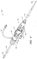
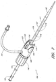
- Figure 4 is a perspective view of an embodiment of a catheter system 100 comprising an introducer catheter 102 (hereinafter referred to as an introducer) and a delivery catheter 104 (hereinafter referred to as the catheter 104).
- the catheter 104 can be configured for the delivery of an endoluminal prosthesis, or for any other suitable use. Therefore, the embodiments of the catheters and introducers disclosed herein can be configured for any suitable purpose, and the embodiments of the introducers disclosed herein can be configured to receive any suitable catheter design.
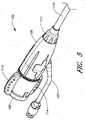
- Figure 5 is a perspective view of the embodiment of the introducer 102 of the embodiment of the catheter system 100 shown in Figure 4 .
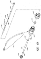
- Figures 6A and 6B are a first and a second exploded assembly view of the embodiment of the introducer 102 shown in Figure 5 .
- the introducer 102 can have a main body 106, a threadably engageable hub portion 108, an introducer sheath 110, and a threaded cap 111 configured to threadably engage with a threaded end portion of the main body 106.
- a first tube 107 can be supported by the main body 106 so as to provide an orifice or access port into the main body 106.
- the first tube 107 can be used to flush the introducer 102 with saline or other suitable substances at any stage, such as but not limited to prior to the advancement of an endoluminal prosthesis through the introducer 102, or prior to other procedures for which an introducer may be used.
- the first tube 107 can support any suitable medical connector and/or valve on the distal end thereof.
- the introducer sheath 110 can have an elongate portion 110a extending to any predetermined or desired length.
- the introducer sheath 110 can be configured such that an endoluminal prosthesis that is advanced into the introducer sheath 110 can be constrained or restrained by the introducer sheath 110.
- the inside and/or outside diameter of the introducer sheath 110 can be approximately the same as or similar to the inside and/or outside diameter of the outer sheath of a delivery catheter that is engaged with the introducer 102.
- the elongate portion 110a can be circular in cross-section (as illustrated), or can define any suitable cross-sectional shape such as without limitation triangular, square, hexagonal, octagonal, or polygonal.
- the introducer sheath 110 can have a flared end portion 110b that can be configured to abut against a fore surface 106a of the main body 106.
- the elongate portion 110a of the introducer sheath 110 can pass through an opening formed in the cap 111 so that the flared portion 110b of the introducer sheath 110 can be engaged with and/or overlap an inside surface of the cap 111.
- the cap 111 supporting the introducer sheath 110 can be threadedly engaged with the main body 106 so that the introducer sheath 110 can be supported by the main body 106.
- a tubular support or spacer 109 can be inserted over the elongate portion 110a of the introducer sheath 110 and positioned approximately adjacent to the flared portion 110b.
- the tubular spacer 109 can improve the fit and, hence, the seal between the outside surface of the introducer sheath 110 and the cap 111.
- the tubular spacer 109 can also provide additional support to the introducer sheath 110.
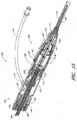
- Figure 7 is a perspective view of the embodiment of the catheter 104 of the embodiment of the catheter system 100 shown in Figure 4 .
- Figures 8A and 8B are a first and second exploded assembly view of the embodiment of the catheter 104 shown in Figure 7 .
- Figure 9 is a perspective view of the embodiment of the catheter system 100 shown in Figure 4 , showing the catheter 104 before the docking mechanism of the catheter 104 has been engaged with the docking mechanism of introducer 102.
- Figure 10 is a perspective view of the embodiment of the catheter system 100 shown in Figure 4 , showing the catheter 104 after the docking mechanism of the catheter 104 has been engaged with the docking mechanism of the introducer 102.
- Figure 11 is an end view of the embodiment of the catheter system shown in Figure 4 , with the catheter 104 engaged with the introducer 102.
- Figure 12 is a section view of the embodiment of the catheter system 100 shown in Figure 4 , taken through the line 12-12 of Figure 11 .
- Figure 13 is an enlarged section view of the embodiment of the catheter system 100 shown in Figure 4 , defined by curve 13-13 of Figure 12 .
- Figure 14 is an enlarged section view of the embodiment of the catheter system shown in Figure 4 , defined by curve 14-14 of Figure 13 .
- Figure 15 is a section view of the embodiment of the catheter system shown in Figure 4 , taken through the line 15-15 of Figure 11 .
- the hub portion 108 of the introducer 102 can have a docking mechanism or flange 112 or can be configured to removably receive or engage with the catheter 104.
- the docking mechanism 112 of the introducer 102 can be configured to be a female receiver, configured to receive a male docking member of the catheter 104, as will be described below.
- the hub portion 108 can comprise one or more tabs 114 configured to improve a user's grip on the hub portion 108, and ability to rotate the hub portion 108 relative to the main body 106.
- the hub portion 108 can be configured to be threadably engageable with the main body 106.
- the main body 108 can define an inner annular surface 116 that can be angled (so as to not be perpendicular to the axial centerline of the catheter system 100).
- the surface 116 can be angled approximately 75 degrees relative to the axial centerline of the catheter system 100, or from approximately 65 degrees or less to approximately 80 degrees or more relative to the axial centerline of the catheter system 100.
- the surface 116 can be approximately perpendicular to the axial centerline of the catheter system 100.
- the hub portion 108 can define an inner annular surface 118 that can be angled so as to not be perpendicular to the axial centerline of the catheter system 100.
- the surface 118 of the hub portion 108 can be angled approximately 75 degrees relative to the axial centerline of the catheter system 100, or from approximately 65 degrees or less to approximately 80 degrees or more and relative to the axial centerline of the catheter system 100 in a direction that is opposite to the direction of the angle defined by the surface 116 of the main body 106.
- the shape and angular orientation of the surface 118 of the hub portion 108 can approximately mirror the shape and angular orientation of the surface 116 of the main body 106.
- the surface 118 can be approximately perpendicular to the axial centerline of the catheter system 100.
- An annular seal member 120 can be supported by the introducer 102 and positioned between the surface 116 of the main body 106 and the surface 118 of the hub portion 108.
- the seal member 120 can be formed from a resilient material, such as silicone, rubber or any other suitable material.
- the seal member 120 can be configured such that, when the hub portion 108 is threaded onto the main body 106, the surface 118 of the hub portion 108 can be moved axially toward the surface 116 of the main body 106, thereby compressing or squeezing the seal member 120.
- the relative angles of the surface 116 of the main body 106 and the surface 118 of the hub portion 108 can cause the seal member 120 to be forced against an outer sheath 122 of the catheter 104 or other component of the catheter 104 that is engaged with the introducer 102, thereby creating an adjustable seal between the outer sheath 122 of the catheter 104, which can project distally from an end portion of the catheter 104, and the introducer 102.
- the level of seal can be adjusted by tightening or loosening the hub portion 108 of the introducer 102 relative to the main body 106 of the introducer 102.
- the introducer 102 can be configured to provide a seal against devices with a profile ranging from 1/3 mm to 6.67 mm in diameter (1 Fr to 20 Fr).
- any of the seals or seal portions described herein can be an interference or close tolerance fit between adjacent components such as, without limitation, the outer sheath 122 and one or more inside surfaces of the main body 106 or the hub portion 108 of the introducer 102.
- any of the seals or seal portions described herein can be an interference or close tolerance fit between the inner core 154 and one or more inside surfaces of the main body 140 or the hub portion 142 of the catheter 104.
- some embodiments of the catheter 104 can comprise a main body 140 and a hub portion 142 threadably engageable with the main body 140.
- Some embodiments of the catheter 104 can also have an outer sheath 122 supported by the main body 140.
- the outer sheath 122 can be removably supported by the main body 140 using a cap 123 threadably supported by the main body 140.
- the outer sheath 122 can have an elongate portion 122a extending to any predetermined or desired length.
- the inside and/or outside diameter of the outer sheath 122 of a catheter 104 can be approximately the same as or similar to the inside and/or outside diameter of the introducer sheath 110.
- the elongate portion 122a can be circular in cross-section (as illustrated), or can define any suitable cross-sectional shape such as without limitation triangular, square, hexagonal, octagonal, or polygonal.
- the outer sheath 122 can have a flared end portion 122b that can be configured to abut against a fore surface 140a of the main body 140.
- the elongate portion 122a of the outer sheath 122 can pass through an opening formed in the cap 123 so that the flared portion 122b of the outer sheath 122 can be engaged with and/or overlap an inside surface of the cap 123.
- the cap 123 supporting the outer sheath 122 can be threadedly engaged with the main body 140 as mentioned above so that the outer sheath 122 is supported by the main body 140.
- a tubular support or spacer 125 can be inserted over the elongate portion 122a of the outer sheath 122 and positioned approximately adjacent to the flared portion 122b of the outer sheath 122.
- the tubular spacer 125 can improve the fit and, hence, the seal between the outside surface of the outer sheath 122 and the cap 123.
- the tubular spacer 125 can also provide additional support to the outer sheath 122.
- the hub portion 142 of the catheter 104 can be configured to be threadably engageable with the main body 140 of the catheter 104.
- the main body 140 can define an inner annular surface 146 that can be angled so as to not be perpendicular to the axial centerline of the catheter system 100.
- the surface 146 can be angled approximately 75 degrees relative to the axial centerline of the catheter system 100, or from approximately 80 degrees or more to approximately 65 degrees or less relative to the axial centerline of the catheter system 100.
- the surface 146 can be approximately perpendicular to the axial centerline of the catheter system 100.
- a second tube 141 can be supported by the main body 140 so as to provide an orifice or access port into the main body 140.
- the second tube 141 can be used to flush the catheter 104 with saline or other suitable substances at any stage, such as but not limited to prior to the advancement of an endoluminal prosthesis through the catheter 104 and/or introducer 102, or prior to other procedures for which an catheter may be used.
- the second tube 141 can support any suitable medical connector and/or valve on the distal end thereof.
- the hub portion 142 can define an inner annular surface 148 that can be angled so as to not be perpendicular to the axial centerline of the catheter system 100.
- the surface 148 of the hub portion 142 can be angled approximately 75 degrees relative to the axial centerline of the catheter system 100, or from approximately 65 degrees or less to approximately 80 degrees or more relative to the axial centerline of the catheter system 100 in a direction that is opposite to the direction of the angle defined by the surface 146 of the main body 140.
- the surface 148 can be approximately perpendicular to the axial centerline of the catheter system 100.
- a seal or seal portion comprising an annular seal member 150 can be supported by the catheter 104 and positioned between the surface 146 of the main body 140 and the surface 148 of the hub portion 142.
- the seal member 150 can be formed from a resilient material, such as silicone, rubber or any other suitable material.
- the seal member 150 can be configured such that, when the hub portion 142 is threaded onto the main body 140, the surface 148 of the hub portion 142 can be moved axially toward the surface 146 of the main body 140, thereby compressing or squeezing the seal member 150.
- the relative angles of the surface 146 of the main body 140 and the surface 148 of the hub portion 142 can cause the seal member 150 to be forced against the inner core 154 of the catheter 104, thereby creating an adjustable seal between the inner core 154 the outer sheath 122 of the catheter 104.
- the level of seal can be adjusted by tightening or loosening the hub portion 142 of the catheter 104 relative to the main body 140 of the catheter 104. Additionally, in some embodiments, the rotational freedom of inner core 154 of the catheter 104 can be inhibited or prevented by tightening the seal member 150 as described above. Thus, the force exerted by the seal member 150 on the inner core 154 can be adjusted to permit the inner core 154 and/or other components to rotate relative to the main body 140 and hub portion 142 of the catheter 104.
- an end portion or cap 158 can be supported at the proximal end of the inner core 154 to facilitate a user's ability to axially slide and/or rotate that inner core 154 relative to the main body 140 and hub portion 142 of the catheter 104.
- the cap 158 can have wings or tabs formed thereon to increase the torque or rotational force that can be exerted on the inner core 154.
- the seal or seal portion within the catheter 104 can be formed from an interference or close tolerance fit between adjacent components such as, without limitation, the inner core 154 and one or more inside surfaces of the main body 140 or the hub portion 142 of the catheter 104.
- the inner core 154 can have a band or other marking 155 near a distal end thereof.
- the marking 155 can be sized, positioned, and configured to provide a visual indication to the medical practitioner as to the location of the end portion 154a of the inner core 154 and/or the location of a catheter tip 162 as the inner core 154 is being advanced into or withdrawn from the introducer 102.
- an additional seal member 160 can be supported by the main body 106 of the introducer 102 to provide an additional seal between the outer sheath 122 of the catheter 104 and the introducer 102.
- the seal 160 can be a flap type seal formed from a conically shaped piece of resilient material such as, but not limited to, rubber having one or more slits therein to allow the distal tip 162 and the outer sheath 122 to pass therethrough.
- a supported flange 161 can be supported within the main body 106 and positioned behind the seal 160 to support the seal 160 and maintain the position of the seal 160 so that the seal 160 does not become inverted when the catheter 104 is removed from the introducer 102.
- the distal tip 162 can be formed from a soft material such as rubber and can be configured to be atraumatic so as to prevent any damage to a patient's vasculature as the catheter 104 is being advanced through the patient's vasculature.
- the docking mechanism 112 of the introducer 102 can be configured to receive a male docking member or portion of the catheter 104.
- one or more deflectable tabs 170 can be supported by the main body 140 of the catheter 104.
- the tabs 170 can be deflected by pressing or exerting a radial inward force against pads 172, causing the ends of the tabs 170 to move radially inward toward the axial centerline of the main body 140.
- the main body 140 of the catheter 104 By deflecting the tabs 170 inwardly, the main body 140 of the catheter 104 can be moved axially into engagement with the hub portion 108 of the introducer 102.
- the tabs 170 can be automatically deflected inwardly when the main body 140 of the catheter 104 is moved axially into engagement with the hub portion 108 of the introducer 102. Once the main body 140 of the catheter 104 is moved axially into engagement with the hub portion 108 of the introducer 102 so as to abut against the hub portion 108 of the introducer, the tabs 170 can be released, thereby removably locking the main body 140 of the catheter 104 to the hub portion 108 of the introducer 102.
- the catheter 104 can be axially engaged with or locked to the introducer 102 so that a user can axially manipulate the introducer 102 and the catheter 104 simultaneously.
- the catheter system 100 is be configured such that at least the inner core 154 of the catheter 104 can be rotated relative to the main body 140 of the catheter 104 and the introducer 102.
- the inner core 154 has a central tube 176 configured to support a stent, such as stent 157 illustrated in Figures 7 and 12-14 .
- a stent such as stent 157 illustrated in Figures 7 and 12-14 .
- one or more beads or tabs 174 can be formed on or supported by the central tube or wire 176.
- the tabs 174 can be configured to increase the axial support or connection between central tube 176 and an endoluminal prosthesis supported by the central tube 176 when the prosthesis is supported in a collapsed configuration by the central tube 176.
- the catheter 104 can be configured such that an opening passes through the distal tip 162, the central tube 176, and the inner core 154.
- the opening can be configured so that at least the distal tip 162, the central tube 176, and the inner core 154 can be advanced over a guidewire positioned within a patient's vasculature, such as is described in U.S. Patent Application No. 12/101,863 filed on April 11, 2008 (titled: BIFURCATED GRAFT DEPLOYMENT SYSTEMS AND METHODS).
- the tabs 174 can be sized, spaced, and otherwise configured to provide axially support to multiple individual stent segments.
- multiple independent or tethered stent segments can be positioned within a tubular or bifurcated graft, and the stent graft can be positioned relative to the tabs 174 such that the tabs 174 are positioned between the stent segments.
- the tabs 174 can be sized, spaced, and otherwise configured so as to be positioned adjacent to the links, bends, loops, and/or other connectors formed in a tubular or bifurcated stent, such as the links, bends, loops, and/or other connectors comprising the embodiments of the stents disclosed in U.S. Patent No. 6,077,296 titled ENDOLUMINAL VASCULAR PROSTHESIS.
- the outer sheath 122 of the catheter 104 can be advanced into an axial opening within the introducer 102 when the catheter 104 is engaged with the introducer 102.
- the outer sheath 122 can be sized and configured such that the distal end portion 122c of the outer sheath 122 can terminate within the introducer 102 prior or proximal to the proximal end or flared portion 110b of the introducer sheath 110.
- the introducer 102 can have a constricted portion 113 formed in the main body 106 of the introducer.
- the catheter system 100 can be configured such that the distal end 122c of the outer sheath 122 terminates prior to or approximately adjacent to a constricted portion 113 of the main body 106 of the introducer 102.
- the distal end portion 122c of the outer sheath 122 can be positioned near to or approximately adjacent to the proximal end portion or the flared portion 110b of the introducer sheath 110, regardless of whether the catheter 104 has a constricted portion 113.
- the inner diameter of the constricted portion 113 can be approximately the same as the inner diameter of the outer sheath 122 and/or the inner diameter of the introducer sheath 110.
- the outer sheath 122 of the catheter 104 and the introducer sheath 110 can be configured to provide a lumen having a generally uniform cross-sectional size through the catheter system through which the endoluminal prosthesis can be advanced.
- the lumen through the catheter system 100 through which the endoluminal prosthesis can be advanced can be substantially continuous, so that the endoluminal prosthesis can be advanced through the catheter system 100 without the prosthesis being obstructed by or snagging on any components or features of the catheter system 100 as it is being advanced.
- the lumen can be substantially continuous but have short gaps on the order of approximately 1 mm to approximately 3 mm in the lumen such as, without limitation, adjacent to the distal end of the outer sheath 122 of the catheter 104 and/or adjacent to the proximal or flared end 110b of the introducer sheath 110.
- short gaps can be formed adjacent to the distal end of the outer sheath 122 of the catheter 104 and/or adjacent to the proximal or flared end 110b of the introducer sheath 110 as some components comprising the catheter system 100 are threadedly engaged with other components comprising the catheter system 100.
- one or more surfaces of other components comprising the catheter 104 or the introducer 102 in addition to the outer sheath 122 and the introducer sheath 110 can form portions of the lumen through the catheter system 100.
- the outer sheath 122 can constrain or restrain an endoluminal prosthesis supported by the central tube 176 as described above.
- an endoluminal prosthesis such as, but not limited to, stent 157 illustrated in Figures 7 and 12-14
- the outer sheath 122 can restrain the endoluminal prosthesis and prevent the endoluminal prosthesis from expanding before reaching the target position within the patient's vasculature.
- the catheter system 100 can be configured such that, as the catheter tip 162, central core 154, and endoluminal prosthesis are advanced past the distal end 122c of the outer sheath 122, the constricted portion 113 and, subsequently, the introducer sheath 110 can radially restrain the endoluminal prosthesis as the endoginanal prosthesis is advanced through the introducer sheath 110.
- the endoluminal prosthesis or the stent 157 can be a tubular stent, a bifurcated stent, or any other desirable stent, graft, stent graft, or endoluminal prosthesis (collectively referred to herein as stent or stents), including without limitation any of the stents or grafts disclosed in U.S. Patent Application No. 12/101,863 referenced above.
- the catheter system 100 or catheter 104 can be configured to deploy any suitable or desirable stent or stents.
- the endoluminal prosthesis can be transferred from the outer sheath 122 to the introducer sheath 110.
- using the introducer sheath 110 as the restraint can allow the outside diameter of the introducer sheath 110 to be reduced, which can minimize trauma to the patient's vasculature and assist in the deployment of the endoluminal prosthesis.
Description
- The present invention relates to catheter systems, in particular, catheter systems having an introducer.
- Introducers or introducer sheaths are used for minimal invasive placement of catheters into blood vessels. They typically consist of a tubing that is inserted into the blood vessel and a seal or valve at the proximal end of the tubing which is positioned outside of the body. The seal provides a hemostasis seal against blood loss. Catheters used for diagnostic or therapeutic means are typically passed through the introducer into the blood vessel. The introducer sheath thus provides continuous access for catheters, protects the inner wall of the blood vessel against damage during catheter insertion, and provides a hemostasis seal against blood loss.
- There are situations in which the catheters require substantial maneuvering within the blood vessel. For example, placement of a stent or stent graft may require the delivery catheter to be positioned precisely axially as well as possible rotationally into a specific location within the blood vessel. In addition deployment of the stent may require precise operation of the delivery system within the introducer. In these situations, the operator has to carefully control both the position of the introducer and the delivery system. This sometimes requires assistance by a second operator.
-
US2006/052750 discloses an expandable transluminal sheath for introduction into the body while in a first, low cross-sectional area configuration, and subsequent expansion of at least a part of the distal end of the sheath to a second, enlarged, cross-sectional configuration, comprising a proximal end and a distal end. The proximal end comprises a proximal sheath tube, a sheath hub, an inner catheter shaft, and outer catheter shaft, and a dilator hub. The dilator hub is coupled to the sheath hub and has a guidewire access port and the catheter shaft has a guidewire lumen. The distal end further comprises a distal sheath tube, the inner catheter shaft, and a balloon. The proximal sheath tube is coupled to the sheath hub, and a valve is operably connected to the sheath hub to seal against fluid loss from the internal lumen of the cathether system. A hemostatic valve is operably connected to the dilator hub and is capable against sealing against a guidewire inserted into the dilator hub, and also against an open lumen. -
US2007/0191775 discloses a sealing catheter hub attachment comprising one or more co-moulded elastomeric gaskets provided to seal against a cannula needle mounted in the catheter hub attachment. -
WO02/36179 EP0875262 discloses a medical insertion device comprising housing, an elastomeric valve, a shuttle tube, and a means for maintaining hemostatis. The elastomeric valve and shuttle tube are located within the interior lumen of the housing, and the shuttle tube is moveable and constructed to bias the elastomeric valve open when moved to a forward position. The means for maintaining hemostatis is any means which can form a fluid tight seal around the periphery of a member to be inserted in the housing. - Some embodiments disclosed herein pertain to a catheter system as defined in the claims for the insertion and positioning of diagnostic or therapeutic devices into blood vessels.
- These and other features, aspects and advantages will now be described in connection with certain, embodiments, in reference to the accompanying drawings. The illustrated embodiments, however, are merely examples and are not intended to be limiting. The following are brief descriptions of the drawings.
-
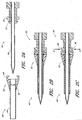
Figure 1A is a schematic representation of an arrangement of a catheter system comprising a docking arrangement to physically engage a catheter with an introducer sheath. -
Figure 1B is a schematic representation of the arrangement of the catheter system shown inFigure 1A , showing the catheter engaged with the introducer sheath. -
Figure 2A is a schematic representation of another arrangement of a catheter system comprising a docking arrangement to physically engage a catheter with an introducer sheath. -
Figure 2B is a schematic representation of the arrangement of the catheter system shown inFigure 2A , showing the catheter engaged with the introducer sheath. -
Figure 2C is a schematic representation of the arrangement of the catheter system shown inFigure 2A , showing a mechanism for disengaging the catheter from the introducer sheath. -
Figure 3A is a schematic representation of another arrangement of a catheter system comprising a docking arrangement to physically engage a catheter with an introducer sheath, the catheter system being configured to deliver a stent or stent graft into a blood vessel. -
Figure 3B is a schematic representation of the arrangement of the catheter system shown inFigure 3A , showing the catheter engaged with the introducer sheath. -
Figure 3C is a schematic representation of the arrangement of the catheter system shown inFigure 3A , illustrating the axial insertion of an arrangement of a stent into the tubular sheath of the arrangement of the introducer sheath shown inFigure 3A . -
Figure 3D is a schematic representation of the arrangement of the catheter system shown inFigure 3A , illustrating the arrangement of the stent being deployed after the tubular sheath of the arrangement of the introducer sheath shown inFigure 3A has been retracted from the stent. -
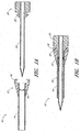
Figure 4 is a perspective view of an embodiment of a catheter system comprising an embodiment of an introducer and an embodiment of a catheter. -
Figure 5 is a perspective view of the embodiment of the introducer shown inFigure 4 . -
Figure 6A is a first exploded assembly view of the embodiment of the introducer shown inFigure 5 . -
Figure 6B is a second exploded assembly view of the embodiment of the introducer shown inFigure 5 . -
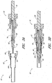
Figure 7 is a perspective view of the embodiment of the delivery catheter shown inFigure 4 . -
Figure 8A is a first exploded assembly view of the embodiment of the catheter shown inFigure 7 . -
Figure 8B is a second exploded assembly view of the embodiment of the catheter shown inFigure 7 . -
Figure 9 is a perspective view of the embodiment of the catheter system shown inFigure 4 , showing the catheter before the docking mechanism of the catheter has been engaged with the docking mechanism of the introducer. -
Figure 10 is a perspective view of the embodiment of the catheter system shown inFigure 4 , showing the delivery catheter after the docking mechanism of the catheter has been engaged with the docking mechanism of the introducer. -
Figure 11 is an end view of the embodiment of the catheter system shown inFigure 4 . -
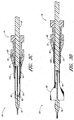
Figure 12 is a section view of the embodiment of the catheter system shown inFigure 4 , taken through the line 12-12 ofFigure 11 . -
Figure 13 is an enlarged section view of the embodiment of the catheter system shown inFigure 4 , defined by curve 13-13 ofFigure 12 . -
Figure 14 is an enlarged section view of the embodiment of the catheter system shown inFigure 4 , defined by curve 14-14 ofFigure 13 . -
Figure 15 is a section view of the embodiment of the catheter system shown inFigure 4 , taken through the line 15-15 ofFigure 11 . - The following detailed description is now directed to certain specific embodiments of the disclosure. In this description, reference is made to the figures wherein like parts are designated with like numerals throughout the description and the drawings. Described below are various arrangement of a catheter system that can comprise an introducer sheath and a docking arrangement. In some arrangement, the catheter systems disclosed herein can be used in diagnostic or therapeutic procedures such as, but not limited to, endoluminal vascular prosthesis deployment procedures.
-
Figure 1A is a schematic representation of an arrangement of acatheter system 10 comprising a docking arrangement configured to physically engage acatheter 20 with anintroducer 12.Figure 1B is a schematic representation of thecatheter system 10 shown inFigure 1A , showing thecatheter 20 engaged with theintroducer 12. In some embodiments, thecatheter 20 or any catheter disclosed herein can be a diagnostic or therapeutic catheter, or any other suitable catheter. In some arrangements, theintroducer 12 can comprise atubular sheath 14, a seal 16, and afemale docking mechanism 18. The first seal 16 can be a rubber seal, an interference or close tolerance fit between adjacent components, an adjustable hemostasis valve, or any other suitable sealing component or feature. - In some arrangements, the
catheter 20 catheter can have ashaft 24 and amale docking mechanism 22. In some arrangements, as illustrated inFig 1B , thecatheter 20 can be inserted into theintroducer 12 and thefemale docking mechanism 18 can be engaged with themale docking mechanism 22. In some arrangements, the docking mechanism can prevent theintroducer 12 and thecatheter 20 from moving axially with respect to each other when the docking mechanism is engaged. Additionally, in some arrangements, thecatheter system 10 can be configured so that thecatheter 20 can rotate within theintroducer 12, even when thecatheter 20 is docked with theintroducer 12. - As mentioned, the
introducer 12 can comprise atubular introducer sheath 14 and a seal 16 (which, again, can be a rubber seal, an interference or close tolerance fit, an adjustable hemostasis valve, or any other suitable sealing component or feature)connected to the proximal end of theintroducer sheath 14. In some arrangements, the overall design of thesheath 14 and seal 16 may be similar to the design of commercially available introducers, or any other introducers presently known or later developed. Thecatheter 20 can have an outside dimensional profile that is sized and/or configured to pass through theintroducer sheath 14. As discussed above, in some arrangements, the proximal end of thecatheter 20 and the proximal end of theintroducer sheath 14 can be configured to permanently or removably engage with each other, and to allow for the rotation of thecatheter 20 within theintroducer sheath 14 while substantially limiting the axial movement of thecatheter 20 with respect to theintroducer sheath 14. - In some arrangements, after engagement of the catheter and introducer, the combined system can be operated by a single operator. As mentioned, the
catheter system 10 can be configured so that thecatheter 20 can substantially freely rotate within theintroducer sheath 14, which can allow for precise rotational positioning of the catheter within the introducer. After completion of the procedure, thecatheter 20 can be disengaged from theintroducer 12 so that thecatheter 20 can be removed from the patient's body. Additionally, theintroducer 12 can be repositioned for a second intervention and a second catheter can be inserted and engaged with theintroducer 12 for additional procedures. -
Figure 2A is a schematic representation of an arrangement of acatheter system 40 comprising a docking arrangement to physically engage acatheter 50 with anintroducer 42.Figure 2B is a schematic representation of the arrangement of thecatheter system 40, showing thecatheter 50 engaged with theintroducer 42.Figure 2C is a schematic representation of the arrangement of thecatheter system 40 shown inFigure 2A , showing a mechanism for disengaging thecatheter 50 from theintroducer 42. - In particular,
Figure 2C schematically illustrate that the catheter.50 can be disengaged from themale docking mechanism 52 and theintroducer 42 by compressing the levers ortabs 56. Accordingly, in the illustrated arrangement, themale docking mechanism 52 can be elongated and can comprise levers 56. -
Figure 3A is a schematic representation of another arrangement of acatheter system 60 comprising a docking arrangement to physically engage acatheter 70 with anintroducer 62, thecatheter system 60 being configured to deliver a stent orstent graft 80 into a blood vessel.Figure 3B is a schematic representation of the arrangement of thecatheter system 60 shown inFigure 3A , showing thecatheter 70 engaged with theintroducer 62.Figure 3C is a schematic representation of the arrangement of thecatheter system 60 shown inFigure 3A , illustrating the axial insertion of an arrangement of a stent orstent graft 80 into thetubular sheath 64 of the arrangement of theintroducer 62 shown inFigure 3A .Figure 3D is a schematic representation of the arrangement of thecatheter system 60 shown inFigure 3A , illustrating the arrangement of thestent 80 being deployed after thetubular sheath 64 of the arrangement of theintroducer 62 shown inFigure 3A has been retracted from thestent 80. - Self-expanding stent or stents grafts are typically retained in a deployment sheath within the catheter. The deployment sheath can protect the stent or stent graft and the vessel wall from damage during insertion and can retain the stent or stent graft in a collapsed low-profile configuration during delivery. The stent or stent graft can be deployed in the desired position of the blood vessel by removing the deployment sheath and allowing the stent or stent graft to radially expand against the wall of the blood vessel. In order to pass such a delivery catheter into the desired blood vessel, the catheter system can be configured so that the inner diameter of the introducer sheath is larger than the outer diameter of the deployment sheath. Clinicians prefer a low profile of the introducer sheath to minimize damage to the blood vessel and allowing for access into small blood vessels. It can be desired to minimize the profile of the catheter.
- Cartridge systems have been developed, in which the stent or stent graft can be transferred from delivery sheath into the introducer sheath and the stent or stent graft can be passed through the introducer sheath to the target location. In such a cartridge system, the introducer sheath effectively acts as a deployment sheath. The transfer eliminates the need of a second sheath and minimizes the profile of the system in the blood vessel. The docking arrangement of the current invention provides a secure engagement of the catheter and the introducer sheath prior to transfer of the stent or stent graft into the introducer sheath. This prevents potential user errors in the transfer and further converts the delivery catheter and introducer sheath into a single-user system.
- As illustrated in
Figures 3A-3D , thecatheter system 60 can be used to transfer and deploy a stent orstent graft 80 into a blood vessel (blood vessel not shown). As illustrated therein, theintroducer 62 can comprise atubular sheath 64 that can be inserted into the body of the patient. Theproximal end 62a of theintroducer 62 can be sized and/or configured to accommodate thedeployment sheath 74 of thecatheter 70. The introducer sheath can also have a seal 66 (referred to herein as a first seal) and afemale docking mechanism 68, similar to any of the embodiments of the seal, hemostasis valve, and/or docking mechanisms described above. Theseal 66 can be an annular rubber seal (as illustrated), an interference or close tolerance fit between adjacent components, an adjustable hemostasis valve, or any other suitable sealing component or feature. Thecatheter 70 can comprise aninner core 78, apocket 82 that can house thecollapsed stent 80, adeployment sheath 74 that can retain thecollapsed stent 80, and acatheter tip 76. - As illustrated in
Figure 3B , in some arrangements, thecatheter 70 can be inserted into theintroducer 62 when thedocking mechanisms deployment sheath 74 of thecatheter 70 can be sized and configured to be received within the larger diameterproximal end 62a of the introducer sheath and to extend into the distaltubular sheath 64 of theintroducer 62. Alternatively, in some arrangements, thedeployment sheath 74 of thecatheter 70 can be sized and configured to be received within the larger diameterproximal end 62a of the introducer sheath but not the distaltubular sheath 64 of theintroducer 62. In some arrangements, as illustrated inFigures 3C and 3D , thedeployment sheath 74 and thetubular sheath 64 can be sized and configured such that, when thedeployment sheath 74 has advanced through theproximal end 62a of the introducer sheath, the similar size or shape of the distaltubular sheath 64 can prevent thedeployment sheath 74 from advancing through the distaltubular sheath 64. In some arrangements, the inner and/or outer diameters of thedeployment sheath 74 and thetubular sheath 64 can be substantially the same. - As illustrated in
Figure 3C , in some arrangements, theinner core 78 of thecatheter 70 can be pushed distally, thereby transferring thestent 80 from thedeployment sheath 74 into thetubular sheath 64 of theintroducer 62. Thestent 80 can be advanced until thecatheter tip 76 reaches the distal end of thetubular sheath 64. In this configuration, the catheter/introducer system effectively becomes a single-unit deployment catheter. Thus, in some arrangements, thetubular sheath 64 can function as a deployment sheath. In some arrangements, thestent 80 can be advanced in a collapsed configuration within theprotective introducer 62 to the target location in the blood vessel without increasing the profile of the delivery system. If the delivery catheter were passed through a traditional introducer sheath, the sheath of the introducer would have to be of a larger diameter than the deployment sheath of the delivery catheter in order to accommodate the stent and the deployment sheath. -
Figure 4 is a perspective view of an embodiment of acatheter system 100 comprising an introducer catheter 102 (hereinafter referred to as an introducer) and a delivery catheter 104 (hereinafter referred to as the catheter 104).. Thecatheter 104 can be configured for the delivery of an endoluminal prosthesis, or for any other suitable use. Therefore, the embodiments of the catheters and introducers disclosed herein can be configured for any suitable purpose, and the embodiments of the introducers disclosed herein can be configured to receive any suitable catheter design. -
Figure 5 is a perspective view of the embodiment of theintroducer 102 of the embodiment of thecatheter system 100 shown inFigure 4 .Figures 6A and6B are a first and a second exploded assembly view of the embodiment of theintroducer 102 shown inFigure 5 . With reference toFigures 4-6 , in some embodiments, theintroducer 102 can have amain body 106, a threadablyengageable hub portion 108, anintroducer sheath 110, and a threadedcap 111 configured to threadably engage with a threaded end portion of themain body 106. - In some embodiments, a
first tube 107 can be supported by themain body 106 so as to provide an orifice or access port into themain body 106. Thefirst tube 107 can be used to flush theintroducer 102 with saline or other suitable substances at any stage, such as but not limited to prior to the advancement of an endoluminal prosthesis through theintroducer 102, or prior to other procedures for which an introducer may be used. Thefirst tube 107 can support any suitable medical connector and/or valve on the distal end thereof. - The
introducer sheath 110 can have anelongate portion 110a extending to any predetermined or desired length. As will be discussed in greater detail below, similar to theintroducer 12 of thecatheter system 10 described above, in some embodiments, theintroducer sheath 110 can be configured such that an endoluminal prosthesis that is advanced into theintroducer sheath 110 can be constrained or restrained by theintroducer sheath 110. In this arrangement, the inside and/or outside diameter of theintroducer sheath 110 can be approximately the same as or similar to the inside and/or outside diameter of the outer sheath of a delivery catheter that is engaged with theintroducer 102. In some embodiments, theelongate portion 110a can be circular in cross-section (as illustrated), or can define any suitable cross-sectional shape such as without limitation triangular, square, hexagonal, octagonal, or polygonal. - Further, as shown most clearly in
Figure 6A , theintroducer sheath 110 can have a flaredend portion 110b that can be configured to abut against afore surface 106a of themain body 106. With reference toFigure 6A , theelongate portion 110a of theintroducer sheath 110 can pass through an opening formed in thecap 111 so that the flaredportion 110b of theintroducer sheath 110 can be engaged with and/or overlap an inside surface of thecap 111. In this configuration, thecap 111 supporting theintroducer sheath 110 can be threadedly engaged with themain body 106 so that theintroducer sheath 110 can be supported by themain body 106. - Additionally, with reference to
Figures 6A and6B , a tubular support orspacer 109 can be inserted over theelongate portion 110a of theintroducer sheath 110 and positioned approximately adjacent to the flaredportion 110b. Thetubular spacer 109 can improve the fit and, hence, the seal between the outside surface of theintroducer sheath 110 and thecap 111. Thetubular spacer 109 can also provide additional support to theintroducer sheath 110. -
Figure 7 is a perspective view of the embodiment of thecatheter 104 of the embodiment of thecatheter system 100 shown inFigure 4 .Figures 8A and8B are a first and second exploded assembly view of the embodiment of thecatheter 104 shown inFigure 7 .Figure 9 is a perspective view of the embodiment of thecatheter system 100 shown inFigure 4 , showing thecatheter 104 before the docking mechanism of thecatheter 104 has been engaged with the docking mechanism ofintroducer 102.Figure 10 is a perspective view of the embodiment of thecatheter system 100 shown inFigure 4 , showing thecatheter 104 after the docking mechanism of thecatheter 104 has been engaged with the docking mechanism of theintroducer 102. -
Figure 11 is an end view of the embodiment of the catheter system shown inFigure 4 , with thecatheter 104 engaged with theintroducer 102.Figure 12 is a section view of the embodiment of thecatheter system 100 shown inFigure 4 , taken through the line 12-12 ofFigure 11 .Figure 13 is an enlarged section view of the embodiment of thecatheter system 100 shown inFigure 4 , defined by curve 13-13 ofFigure 12 .Figure 14 is an enlarged section view of the embodiment of the catheter system shown inFigure 4 , defined by curve 14-14 ofFigure 13 . Finally,Figure 15 is a section view of the embodiment of the catheter system shown inFigure 4 , taken through the line 15-15 ofFigure 11 . - As shown most clearly in
Figures 12 and15 , thehub portion 108 of theintroducer 102 can have a docking mechanism orflange 112 or can be configured to removably receive or engage with thecatheter 104. In some embodiments, as in the illustrated embodiment, thedocking mechanism 112 of theintroducer 102 can be configured to be a female receiver, configured to receive a male docking member of thecatheter 104, as will be described below. In some embodiments, thehub portion 108 can comprise one ormore tabs 114 configured to improve a user's grip on thehub portion 108, and ability to rotate thehub portion 108 relative to themain body 106. - With reference to
Figures 12 ,13 , and15 , some embodiments of the seal portion of theintroducer 102 will be described. As mentioned above, thehub portion 108 can be configured to be threadably engageable with themain body 106. In some embodiments, themain body 108 can define an innerannular surface 116 that can be angled (so as to not be perpendicular to the axial centerline of the catheter system 100). In some embodiments, thesurface 116 can be angled approximately 75 degrees relative to the axial centerline of thecatheter system 100, or from approximately 65 degrees or less to approximately 80 degrees or more relative to the axial centerline of thecatheter system 100. In some embodiments, thesurface 116 can be approximately perpendicular to the axial centerline of thecatheter system 100. - Similarly, in some embodiments, the
hub portion 108 can define an innerannular surface 118 that can be angled so as to not be perpendicular to the axial centerline of thecatheter system 100. In some embodiments, thesurface 118 of thehub portion 108 can be angled approximately 75 degrees relative to the axial centerline of thecatheter system 100, or from approximately 65 degrees or less to approximately 80 degrees or more and relative to the axial centerline of thecatheter system 100 in a direction that is opposite to the direction of the angle defined by thesurface 116 of themain body 106. In some embodiments, as in the illustrated embodiment, the shape and angular orientation of thesurface 118 of thehub portion 108 can approximately mirror the shape and angular orientation of thesurface 116 of themain body 106. In some embodiments, thesurface 118 can be approximately perpendicular to the axial centerline of thecatheter system 100. - An
annular seal member 120 can be supported by theintroducer 102 and positioned between thesurface 116 of themain body 106 and thesurface 118 of thehub portion 108. Theseal member 120 can be formed from a resilient material, such as silicone, rubber or any other suitable material. Theseal member 120 can be configured such that, when thehub portion 108 is threaded onto themain body 106, thesurface 118 of thehub portion 108 can be moved axially toward thesurface 116 of themain body 106, thereby compressing or squeezing theseal member 120. The relative angles of thesurface 116 of themain body 106 and thesurface 118 of thehub portion 108 can cause theseal member 120 to be forced against anouter sheath 122 of thecatheter 104 or other component of thecatheter 104 that is engaged with theintroducer 102, thereby creating an adjustable seal between theouter sheath 122 of thecatheter 104, which can project distally from an end portion of thecatheter 104, and theintroducer 102. In some embodiments, the level of seal can be adjusted by tightening or loosening thehub portion 108 of theintroducer 102 relative to themain body 106 of theintroducer 102. In some embodiments, theintroducer 102 can be configured to provide a seal against devices with a profile ranging from 1/3 mm to 6.67 mm in diameter (1 Fr to 20 Fr). - Alternatively, in some embodiments, any of the seals or seal portions described herein can be an interference or close tolerance fit between adjacent components such as, without limitation, the
outer sheath 122 and one or more inside surfaces of themain body 106 or thehub portion 108 of theintroducer 102. In some embodiments, any of the seals or seal portions described herein can be an interference or close tolerance fit between theinner core 154 and one or more inside surfaces of themain body 140 or thehub portion 142 of thecatheter 104. - As shown in
Figures 7 ,8A , and8B , some embodiments of thecatheter 104 can comprise amain body 140 and ahub portion 142 threadably engageable with themain body 140. Some embodiments of thecatheter 104 can also have anouter sheath 122 supported by themain body 140. In particular, theouter sheath 122 can be removably supported by themain body 140 using acap 123 threadably supported by themain body 140. Further, in some embodiments, theouter sheath 122 can have anelongate portion 122a extending to any predetermined or desired length. - As mentioned above, in some embodiments, the inside and/or outside diameter of the
outer sheath 122 of acatheter 104 can be approximately the same as or similar to the inside and/or outside diameter of theintroducer sheath 110. In some embodiments, theelongate portion 122a can be circular in cross-section (as illustrated), or can define any suitable cross-sectional shape such as without limitation triangular, square, hexagonal, octagonal, or polygonal. - The
outer sheath 122 can have a flaredend portion 122b that can be configured to abut against afore surface 140a of themain body 140. With reference toFigure 8A , theelongate portion 122a of theouter sheath 122 can pass through an opening formed in thecap 123 so that the flaredportion 122b of theouter sheath 122 can be engaged with and/or overlap an inside surface of thecap 123. In this configuration, thecap 123 supporting theouter sheath 122 can be threadedly engaged with themain body 140 as mentioned above so that theouter sheath 122 is supported by themain body 140. - Additionally, with reference to
Figures 8A and8B , a tubular support orspacer 125 can be inserted over theelongate portion 122a of theouter sheath 122 and positioned approximately adjacent to the flaredportion 122b of theouter sheath 122. Thetubular spacer 125 can improve the fit and, hence, the seal between the outside surface of theouter sheath 122 and thecap 123. Thetubular spacer 125 can also provide additional support to theouter sheath 122. - Similar to the
hub portion 108 of theintroducer 102, thehub portion 142 of thecatheter 104 can be configured to be threadably engageable with themain body 140 of thecatheter 104. In some embodiments, themain body 140 can define an innerannular surface 146 that can be angled so as to not be perpendicular to the axial centerline of thecatheter system 100. In some embodiments, thesurface 146 can be angled approximately 75 degrees relative to the axial centerline of thecatheter system 100, or from approximately 80 degrees or more to approximately 65 degrees or less relative to the axial centerline of thecatheter system 100. In some embodiments, thesurface 146 can be approximately perpendicular to the axial centerline of thecatheter system 100. - In some embodiments, a
second tube 141 can be supported by themain body 140 so as to provide an orifice or access port into themain body 140. Thesecond tube 141 can be used to flush thecatheter 104 with saline or other suitable substances at any stage, such as but not limited to prior to the advancement of an endoluminal prosthesis through thecatheter 104 and/orintroducer 102, or prior to other procedures for which an catheter may be used. Thesecond tube 141 can support any suitable medical connector and/or valve on the distal end thereof. - Similarly, in some embodiments, the
hub portion 142 can define an innerannular surface 148 that can be angled so as to not be perpendicular to the axial centerline of thecatheter system 100. In some embodiments, thesurface 148 of thehub portion 142 can be angled approximately 75 degrees relative to the axial centerline of thecatheter system 100, or from approximately 65 degrees or less to approximately 80 degrees or more relative to the axial centerline of thecatheter system 100 in a direction that is opposite to the direction of the angle defined by thesurface 146 of themain body 140. In some embodiments, thesurface 148 can be approximately perpendicular to the axial centerline of thecatheter system 100. - Similar to that of the introducer, in some embodiments, a seal or seal portion comprising an
annular seal member 150 can be supported by thecatheter 104 and positioned between thesurface 146 of themain body 140 and thesurface 148 of thehub portion 142. Theseal member 150 can be formed from a resilient material, such as silicone, rubber or any other suitable material. Theseal member 150 can be configured such that, when thehub portion 142 is threaded onto themain body 140, thesurface 148 of thehub portion 142 can be moved axially toward thesurface 146 of themain body 140, thereby compressing or squeezing theseal member 150. The relative angles of thesurface 146 of themain body 140 and thesurface 148 of thehub portion 142 can cause theseal member 150 to be forced against theinner core 154 of thecatheter 104, thereby creating an adjustable seal between theinner core 154 theouter sheath 122 of thecatheter 104. - In some embodiments, the level of seal can be adjusted by tightening or loosening the
hub portion 142 of thecatheter 104 relative to themain body 140 of thecatheter 104. Additionally, in some embodiments, the rotational freedom ofinner core 154 of thecatheter 104 can be inhibited or prevented by tightening theseal member 150 as described above. Thus, the force exerted by theseal member 150 on theinner core 154 can be adjusted to permit theinner core 154 and/or other components to rotate relative to themain body 140 andhub portion 142 of thecatheter 104. As illustrated inFigure 4 , an end portion or cap 158 can be supported at the proximal end of theinner core 154 to facilitate a user's ability to axially slide and/or rotate thatinner core 154 relative to themain body 140 andhub portion 142 of thecatheter 104. In some embodiments, thecap 158 can have wings or tabs formed thereon to increase the torque or rotational force that can be exerted on theinner core 154. Alternatively, in some embodiments, the seal or seal portion within thecatheter 104 can be formed from an interference or close tolerance fit between adjacent components such as, without limitation, theinner core 154 and one or more inside surfaces of themain body 140 or thehub portion 142 of thecatheter 104. - In some embodiments, the
inner core 154 can have a band or other marking 155 near a distal end thereof. The marking 155 can be sized, positioned, and configured to provide a visual indication to the medical practitioner as to the location of theend portion 154a of theinner core 154 and/or the location of acatheter tip 162 as theinner core 154 is being advanced into or withdrawn from theintroducer 102. - In some embodiments, as illustrated most clearly in
Figures 12 and13 , anadditional seal member 160 can be supported by themain body 106 of theintroducer 102 to provide an additional seal between theouter sheath 122 of thecatheter 104 and theintroducer 102. In some embodiments, theseal 160 can be a flap type seal formed from a conically shaped piece of resilient material such as, but not limited to, rubber having one or more slits therein to allow thedistal tip 162 and theouter sheath 122 to pass therethrough. In some embodiments, a supportedflange 161 can be supported within themain body 106 and positioned behind theseal 160 to support theseal 160 and maintain the position of theseal 160 so that theseal 160 does not become inverted when thecatheter 104 is removed from theintroducer 102. In some embodiments, thedistal tip 162 can be formed from a soft material such as rubber and can be configured to be atraumatic so as to prevent any damage to a patient's vasculature as thecatheter 104 is being advanced through the patient's vasculature. - As mentioned above, in some embodiments, as in the illustrated embodiment, the
docking mechanism 112 of theintroducer 102 can be configured to receive a male docking member or portion of thecatheter 104. In particular, with reference toFigures 7 ,8A and8B , one or moredeflectable tabs 170 can be supported by themain body 140 of thecatheter 104. In some embodiments, thetabs 170 can be deflected by pressing or exerting a radial inward force againstpads 172, causing the ends of thetabs 170 to move radially inward toward the axial centerline of themain body 140. By deflecting thetabs 170 inwardly, themain body 140 of thecatheter 104 can be moved axially into engagement with thehub portion 108 of theintroducer 102. In some embodiments, thetabs 170 can be automatically deflected inwardly when themain body 140 of thecatheter 104 is moved axially into engagement with thehub portion 108 of theintroducer 102. Once themain body 140 of thecatheter 104 is moved axially into engagement with thehub portion 108 of theintroducer 102 so as to abut against thehub portion 108 of the introducer, thetabs 170 can be released, thereby removably locking themain body 140 of thecatheter 104 to thehub portion 108 of theintroducer 102. - In this configuration, the
catheter 104 can be axially engaged with or locked to theintroducer 102 so that a user can axially manipulate theintroducer 102 and thecatheter 104 simultaneously. Additionally, in this configuration, as discussed above, thecatheter system 100 is be configured such that at least theinner core 154 of thecatheter 104 can be rotated relative to themain body 140 of thecatheter 104 and theintroducer 102. - In the embodiment, as shown in
Figures 7 ,8A , and8B , theinner core 154 has acentral tube 176 configured to support a stent, such asstent 157 illustrated inFigures 7 and12-14 . Additionally, one or more beads ortabs 174 can be formed on or supported by the central tube orwire 176. Thetabs 174 can be configured to increase the axial support or connection betweencentral tube 176 and an endoluminal prosthesis supported by thecentral tube 176 when the prosthesis is supported in a collapsed configuration by thecentral tube 176. In some embodiments, thecatheter 104 can be configured such that an opening passes through thedistal tip 162, thecentral tube 176, and theinner core 154. The opening can be configured so that at least thedistal tip 162, thecentral tube 176, and theinner core 154 can be advanced over a guidewire positioned within a patient's vasculature, such as is described inU.S. Patent Application No. 12/101,863 filed on April 11, 2008 - Additionally, in some embodiments (not illustrated), the
tabs 174 can be sized, spaced, and otherwise configured to provide axially support to multiple individual stent segments. For example, without limitation, multiple independent or tethered stent segments can be positioned within a tubular or bifurcated graft, and the stent graft can be positioned relative to thetabs 174 such that thetabs 174 are positioned between the stent segments. This arrangement can reduce the overall diameter of theouter sheath 122, theintroducer sheath 110, and other components comprising the catheter system, can enhance the axial support provided by thetabs 174 to the endoluminal prosthesis, and can allow for a more uniform distribution of support forces between thetabs 174 and the endoluminal prosthesis. In some embodiments, thetabs 174 can be sized, spaced, and otherwise configured so as to be positioned adjacent to the links, bends, loops, and/or other connectors formed in a tubular or bifurcated stent, such as the links, bends, loops, and/or other connectors comprising the embodiments of the stents disclosed inU.S. Patent No. 6,077,296 titled ENDOLUMINAL VASCULAR PROSTHESIS. - With reference to
Figures 13-15 , theouter sheath 122 of thecatheter 104 can be advanced into an axial opening within theintroducer 102 when thecatheter 104 is engaged with theintroducer 102. In some embodiments, theouter sheath 122 can be sized and configured such that thedistal end portion 122c of theouter sheath 122 can terminate within theintroducer 102 prior or proximal to the proximal end or flaredportion 110b of theintroducer sheath 110. Although not required, theintroducer 102 can have a constrictedportion 113 formed in themain body 106 of the introducer. In some embodiments, as shown most clearly inFigure 14 , thecatheter system 100 can be configured such that thedistal end 122c of theouter sheath 122 terminates prior to or approximately adjacent to aconstricted portion 113 of themain body 106 of theintroducer 102. - In some embodiments (not illustrated), the
distal end portion 122c of theouter sheath 122 can be positioned near to or approximately adjacent to the proximal end portion or the flaredportion 110b of theintroducer sheath 110, regardless of whether thecatheter 104 has a constrictedportion 113. The inner diameter of theconstricted portion 113 can be approximately the same as the inner diameter of theouter sheath 122 and/or the inner diameter of theintroducer sheath 110. - Therefore, in some embodiments, the
outer sheath 122 of thecatheter 104 and theintroducer sheath 110 can be configured to provide a lumen having a generally uniform cross-sectional size through the catheter system through which the endoluminal prosthesis can be advanced. In some embodiments, the lumen through thecatheter system 100 through which the endoluminal prosthesis can be advanced can be substantially continuous, so that the endoluminal prosthesis can be advanced through thecatheter system 100 without the prosthesis being obstructed by or snagging on any components or features of thecatheter system 100 as it is being advanced. In some embodiments, the lumen can be substantially continuous but have short gaps on the order of approximately 1 mm to approximately 3 mm in the lumen such as, without limitation, adjacent to the distal end of theouter sheath 122 of thecatheter 104 and/or adjacent to the proximal or flaredend 110b of theintroducer sheath 110. For example, in some embodiments, short gaps can be formed adjacent to the distal end of theouter sheath 122 of thecatheter 104 and/or adjacent to the proximal or flaredend 110b of theintroducer sheath 110 as some components comprising thecatheter system 100 are threadedly engaged with other components comprising thecatheter system 100. Further, in some embodiments, one or more surfaces of other components comprising thecatheter 104 or theintroducer 102 in addition to theouter sheath 122 and theintroducer sheath 110, such as without limitation theconstricted portion 113 of themain body 106 of theintroducer 102 as discussed above, can form portions of the lumen through thecatheter system 100. - In some embodiments, the
outer sheath 122 can constrain or restrain an endoluminal prosthesis supported by thecentral tube 176 as described above. In this configuration, as thecatheter tip 162,central core 154, and an endoluminal prosthesis (such as, but not limited to,stent 157 illustrated inFigures 7 and12-14 ) are advanced through theouter sheath 122, theouter sheath 122 can restrain the endoluminal prosthesis and prevent the endoluminal prosthesis from expanding before reaching the target position within the patient's vasculature. Additionally, thecatheter system 100 can be configured such that, as thecatheter tip 162,central core 154, and endoluminal prosthesis are advanced past thedistal end 122c of theouter sheath 122, theconstricted portion 113 and, subsequently, theintroducer sheath 110 can radially restrain the endoluminal prosthesis as the endoluniinal prosthesis is advanced through theintroducer sheath 110. - In some embodiments, the endoluminal prosthesis or the
stent 157 can be a tubular stent, a bifurcated stent, or any other desirable stent, graft, stent graft, or endoluminal prosthesis (collectively referred to herein as stent or stents), including without limitation any of the stents or grafts disclosed inU.S. Patent Application No. 12/101,863 referenced above. Accordingly in some embodiments, thecatheter system 100 orcatheter 104 can be configured to deploy any suitable or desirable stent or stents. - Thus, in this configuration, the endoluminal prosthesis can be transferred from the
outer sheath 122 to theintroducer sheath 110. In this arrangement, using theintroducer sheath 110 as the restraint can allow the outside diameter of theintroducer sheath 110 to be reduced, which can minimize trauma to the patient's vasculature and assist in the deployment of the endoluminal prosthesis. - Many arrangements and embodiments of the docking mechanism and catheter system have been described in connection with
Figures 1-15 . It will apparent to one of ordinary skill in the art that there are many potential embodiments of a permanent or removable docking mechanism that may be suitable for medical use and which are contemplated herein. - As will be recognized, certain embodiments described herein may be embodied within a form that does not provide all of the features and benefits set forth herein, as some features may be used or practiced separately from others. The scope of the inventions is indicated by the appended claims rather than by the foregoing description.
Claims (14)
- A catheter system comprising:an introducer 102 comprising a main body 106, a tubular introducer sheath 110 projecting from the main body 106, and a first seal 120 supported within the introducer 102;a catheter 104 comprising a main body 140, an outer sheath 122 projecting from the main body 140, a second seal 150 supported within the catheter 104, and an inner core 154 wherein:characterized in that the inner core has a central tube 176 and is advanceable through the main body 140, the second seal 150, and the outer sheath 122 and is rotatable relative to the main body 140.the first seal 120 is configured to at least inhibit a flow of blood through the introducer 102;the second seal 150 is configured to at least inhibit a flow of blood through the catheter 104;the introducer sheath 110 is configured to axially receive at least the inner core 154 therethrough;the introducer 102 is removably engaged with the catheter such that the catheter is rotatable relative to the introducer but axial movement of one of the introducer and the catheter will cause the simultaneous and equal axial movement of the other of the introducer and the catheter;
- The catheter system of Claim 1, wherein the catheter comprises at least one deflectable tab and the introducer comprises at least one flange, wherein the introducer 102 is removably axially engaged with the catheter 104 with the at least one deflectable tab and at least one flange.
- The catheter system of any one of the previous claims, wherein the catheter system further comprises a stent 157 and the catheter is configured to deploy the stent 157.
- The catheter system of any one of the previous claims, wherein the catheter system is configured such that the outer sheath 122 of the catheter 104 does not overlap any portion of the introducer sheath 110 when the catheter is axially engaged with the introducer 102.
- The catheter system of any one of the previous claims, wherein the outer sheath 122 defines a proximal end portion supported by the catheter and a distal end portion, and the introducer sheath 110 defines a proximal end portion supported by the introducer 102 and a distal end portion, and the distal end portion of the outer sheath 122 is positioned approximately adjacent to the proximal end portion of the introducer sheath 110 when the catheter 104 is axially engaged with the introducer 102.
- The catheter system of Claim 5, wherein the introducer sheath 110 is configured to directly radially restrain a stent that is axially supported by the catheter after the stent has been axially advanced past the distal end portion of the outer sheath 122.
- The catheter system of any one of the previous claims, wherein an inner diameter of the outer sheath 122 is approximately the same as an inner diameter of the introducer sheath 110.
- The catheter system of any one of the previous claims, wherein the central tube 176 is axially supported by and projecting from the inner core, the central tube being configured to support a stent thereon, the catheter being configured such that the central tube and the stent are axially advanceable through at least the main body of the catheter and the outer sheath of the catheter by axially advancing the inner core.
- The catheter system of Claim 8, further comprising one or more tabs 174 supported by the central tube, the one or more tabs being configured to provide axial support to the stent that is supported by the catheter when the stent is in a collapsed configuration.
- The catheter system of Claim 8, wherein the catheter further comprises a distal tip 162 supported by an end portion of the central tube, and both the distal tip and the central tube have an opening therethrough configured to receive a guidewire.
- The catheter system of any one of the previous claims, wherein the catheter system is configured such that a stent can be transferred from the outer sheath 122 into the introducer sheath 110 as the stent is advanced into the introducer.
- The catheter system of any one of the previous claims, wherein the outer sheath 122 and the introducer sheath form a lumen having a substantially uniform cross-sectional size through the catheter system through which a stent can be advanced.
- The catheter system of any one of Claims 2-12, wherein the catheter 104 can be disengaged from the introducer 102 by deflecting the at least one deflectable tab 170 radially inwardly and axially retracting the catheter away from the introducer.
- The catheter system of any one of the previous claims, wherein the introducer 102 comprises a female docking mechanism 112 and the catheter comprises a male docking mechanism 170, wherein the male docking mechanism 170 of the catheter 104 is selectively engageable with the female docking mechanism 112 of the introducer so that the catheter 104 can be selectively and removably linked with the introducer 102 in the axial direction such that the introducer 102 and catheter 104 can be simultaneously axially manipulated.
Applications Claiming Priority (3)
| Application Number | Priority Date | Filing Date | Title |
|---|---|---|---|
| US7742908P | 2008-07-01 | 2008-07-01 | |
| US18474209P | 2009-06-05 | 2009-06-05 | |
| EP09774381A EP2293838B1 (en) | 2008-07-01 | 2009-06-30 | Catheter system |
Related Parent Applications (2)
| Application Number | Title | Priority Date | Filing Date |
|---|---|---|---|
| EP09774381A Division EP2293838B1 (en) | 2008-07-01 | 2009-06-30 | Catheter system |
| EP09774381.9 Division | 2009-06-30 |
Publications (2)
| Publication Number | Publication Date |
|---|---|
| EP2520320A1 EP2520320A1 (en) | 2012-11-07 |
| EP2520320B1 true EP2520320B1 (en) | 2016-11-02 |
Family
ID=41119392
Family Applications (2)
| Application Number | Title | Priority Date | Filing Date |
|---|---|---|---|
| EP09774381A Active EP2293838B1 (en) | 2008-07-01 | 2009-06-30 | Catheter system |
| EP12178965.5A Active EP2520320B1 (en) | 2008-07-01 | 2009-06-30 | Catheter system |
Family Applications Before (1)
| Application Number | Title | Priority Date | Filing Date |
|---|---|---|---|
| EP09774381A Active EP2293838B1 (en) | 2008-07-01 | 2009-06-30 | Catheter system |
Country Status (4)
| Country | Link |
|---|---|
| US (4) | US8216295B2 (en) |
| EP (2) | EP2293838B1 (en) |
| JP (1) | JP5134729B2 (en) |
| WO (1) | WO2010002931A1 (en) |
Families Citing this family (109)
| Publication number | Priority date | Publication date | Assignee | Title |
|---|---|---|---|---|
| US6261316B1 (en) | 1999-03-11 | 2001-07-17 | Endologix, Inc. | Single puncture bifurcation graft deployment system |
| US8034100B2 (en) * | 1999-03-11 | 2011-10-11 | Endologix, Inc. | Graft deployment system |
| US11259945B2 (en) | 2003-09-03 | 2022-03-01 | Bolton Medical, Inc. | Dual capture device for stent graft delivery system and method for capturing a stent graft |
| US20080071343A1 (en) * | 2006-09-15 | 2008-03-20 | Kevin John Mayberry | Multi-segmented graft deployment system |
| US9387308B2 (en) * | 2007-04-23 | 2016-07-12 | Cardioguidance Biomedical, Llc | Guidewire with adjustable stiffness |
| CA2697364C (en) | 2007-08-23 | 2017-10-17 | Direct Flow Medical, Inc. | Translumenally implantable heart valve with formed in place support |
| US8221494B2 (en) | 2008-02-22 | 2012-07-17 | Endologix, Inc. | Apparatus and method of placement of a graft or graft system |
| US9421065B2 (en) | 2008-04-02 | 2016-08-23 | The Spectranetics Corporation | Liquid light-guide catheter with optically diverging tip |
| US8979828B2 (en) | 2008-07-21 | 2015-03-17 | The Spectranetics Corporation | Tapered liquid light guide |
| US8236040B2 (en) | 2008-04-11 | 2012-08-07 | Endologix, Inc. | Bifurcated graft deployment systems and methods |
| JP5484458B2 (en) | 2008-06-30 | 2014-05-07 | ボルトン メディカル インコーポレイテッド | Abdominal aortic aneurysm system |
| EP2293838B1 (en) | 2008-07-01 | 2012-08-08 | Endologix, Inc. | Catheter system |
| CN106551740B (en) | 2009-03-13 | 2020-03-27 | 波顿医疗公司 | System and method for deploying an endoluminal prosthesis at a surgical site |
| EP2429452B1 (en) | 2009-04-28 | 2020-01-15 | Endologix, Inc. | Endoluminal prosthesis system |
| US10772717B2 (en) | 2009-05-01 | 2020-09-15 | Endologix, Inc. | Percutaneous method and device to treat dissections |
| WO2010127305A2 (en) * | 2009-05-01 | 2010-11-04 | Endologix, Inc. | Percutaneous method and device to treat dissections |
| EP2459127B1 (en) | 2009-07-27 | 2015-09-23 | Endologix, Inc. | Stent graft |
| EP2496189A4 (en) * | 2009-11-04 | 2016-05-11 | Nitinol Devices And Components Inc | Alternating circumferential bridge stent design and methods for use thereof |
| CN102188300B (en) * | 2010-03-02 | 2014-05-28 | 上海微创医疗器械(集团)有限公司 | Aneurismal surgical device |
| EP2555824A4 (en) * | 2010-04-08 | 2013-09-11 | Bio2Medical Inc | Catheter hub |
| US9603708B2 (en) | 2010-05-19 | 2017-03-28 | Dfm, Llc | Low crossing profile delivery catheter for cardiovascular prosthetic implant |
| US8864811B2 (en) * | 2010-06-08 | 2014-10-21 | Veniti, Inc. | Bi-directional stent delivery system |
| US9301864B2 (en) * | 2010-06-08 | 2016-04-05 | Veniti, Inc. | Bi-directional stent delivery system |
| EP2399639A1 (en) | 2010-06-25 | 2011-12-28 | ECP Entwicklungsgesellschaft mbH | System for introducing a pump |
| US8419783B2 (en) | 2010-07-07 | 2013-04-16 | Cook Medical Technologies Llc | Graft deployment assist tool |
| US9233014B2 (en) | 2010-09-24 | 2016-01-12 | Veniti, Inc. | Stent with support braces |
| EP2624791B1 (en) | 2010-10-08 | 2017-06-21 | Confluent Medical Technologies, Inc. | Alternating circumferential bridge stent design |
| EP2635241B1 (en) | 2010-11-02 | 2019-02-20 | Endologix, Inc. | Apparatus for placement of a graft or graft system |
| US9775982B2 (en) | 2010-12-29 | 2017-10-03 | Medtronic, Inc. | Implantable medical device fixation |
| US10112045B2 (en) | 2010-12-29 | 2018-10-30 | Medtronic, Inc. | Implantable medical device fixation |
| US8808350B2 (en) * | 2011-03-01 | 2014-08-19 | Endologix, Inc. | Catheter system and methods of using same |
| US9162038B2 (en) * | 2011-04-11 | 2015-10-20 | The Spectranetics Corporation | Needle and guidewire holder |
| US10010412B2 (en) * | 2011-07-27 | 2018-07-03 | Edwards Lifesciences Corporation | Conical crimper |
| US10213329B2 (en) | 2011-08-12 | 2019-02-26 | W. L. Gore & Associates, Inc. | Evertable sheath devices, systems, and methods |
| RU2014109380A (en) | 2011-08-12 | 2015-09-20 | В.Л. Гор Энд Ассошиейтс, Инк. | DEVICES AND METHODS FOR APPROXIMATING THE PROFILE OF THE CROSS SECTION OF THE VASCULAR SYSTEM HAVING BRANCH |
| CN102429687B (en) * | 2011-08-18 | 2013-12-18 | 曲乐丰 | Stent distracting vena cava membrane breaker |
| US9782282B2 (en) | 2011-11-14 | 2017-10-10 | W. L. Gore & Associates, Inc. | External steerable fiber for use in endoluminal deployment of expandable devices |
| US9877858B2 (en) | 2011-11-14 | 2018-01-30 | W. L. Gore & Associates, Inc. | External steerable fiber for use in endoluminal deployment of expandable devices |
| US9561347B2 (en) * | 2011-11-16 | 2017-02-07 | W. L. Gore & Associates, Inc. | Introducer sheath assembly having a locking dilator |
| EP2606919A1 (en) | 2011-12-22 | 2013-06-26 | ECP Entwicklungsgesellschaft mbH | Sluice device for inserting a catheter |
| EP2606920A1 (en) | 2011-12-22 | 2013-06-26 | ECP Entwicklungsgesellschaft mbH | Sluice device for inserting a catheter |
| WO2013101641A2 (en) * | 2011-12-29 | 2013-07-04 | Rotation Medical, Inc. | Anatomical location markers and methods of use in positioning sheet-like materials during surgery |
| EP2802375B1 (en) * | 2012-01-13 | 2019-03-27 | Teleflex Medical, Incorporated | Novel bumped dilator tip |
| US9474884B2 (en) | 2012-01-13 | 2016-10-25 | Teleflex Medical Incorporated | Bumped dilator tip |
| US9687371B2 (en) | 2012-02-14 | 2017-06-27 | W. L. Gore & Associates, Inc. | Endoprosthesis having aligned legs for ease of cannulation |
| US9375308B2 (en) | 2012-03-13 | 2016-06-28 | W. L. Gore & Associates, Inc. | External steerable fiber for use in endoluminal deployment of expandable devices |
| US9854982B2 (en) | 2012-03-26 | 2018-01-02 | Medtronic, Inc. | Implantable medical device deployment within a vessel |
| US20130253342A1 (en) * | 2012-03-26 | 2013-09-26 | Medtronic, Inc. | Pass-through implantable medical device delivery catheter |
| US10485435B2 (en) * | 2012-03-26 | 2019-11-26 | Medtronic, Inc. | Pass-through implantable medical device delivery catheter with removeable distal tip |
| US9220906B2 (en) | 2012-03-26 | 2015-12-29 | Medtronic, Inc. | Tethered implantable medical device deployment |
| US9339197B2 (en) | 2012-03-26 | 2016-05-17 | Medtronic, Inc. | Intravascular implantable medical device introduction |
| US9717421B2 (en) | 2012-03-26 | 2017-08-01 | Medtronic, Inc. | Implantable medical device delivery catheter with tether |
| US9833625B2 (en) | 2012-03-26 | 2017-12-05 | Medtronic, Inc. | Implantable medical device delivery with inner and outer sheaths |
| US10098767B2 (en) * | 2012-04-27 | 2018-10-16 | Medtronic Vascular, Inc. | Reconfigurable stent-graft delivery system and method of use |
| US9445897B2 (en) * | 2012-05-01 | 2016-09-20 | Direct Flow Medical, Inc. | Prosthetic implant delivery device with introducer catheter |
| US9456842B2 (en) * | 2012-07-13 | 2016-10-04 | Boston Scientific Scimed, Inc. | Wire-guided recanalization system |
| EP2745869A1 (en) * | 2012-12-21 | 2014-06-25 | ECP Entwicklungsgesellschaft mbH | Sluice assembly for the introduction of a cord-like body, in particular of a catheter, into a patient |
| US10039898B2 (en) * | 2013-01-08 | 2018-08-07 | Biosense Webster (Israel) Ltd. | Catheter sheath introducer with directional retention damper |
| US9763819B1 (en) | 2013-03-05 | 2017-09-19 | W. L. Gore & Associates, Inc. | Tapered sleeve |
| US9987155B1 (en) | 2013-03-07 | 2018-06-05 | W. L. Gore & Associates, Inc. | Implantable medical devices and related delivery systems |
| US20140277358A1 (en) * | 2013-03-13 | 2014-09-18 | DePuy Synthes Products, LLC | Striped stent introducer |
| US9439751B2 (en) | 2013-03-15 | 2016-09-13 | Bolton Medical, Inc. | Hemostasis valve and delivery systems |
| US9364357B2 (en) | 2013-05-08 | 2016-06-14 | Cook Medical Technologies Llc | Delivery catheter including collapsible sleeve and method of operating same |
| US9545325B2 (en) * | 2013-08-08 | 2017-01-17 | Covidien Lp | Medical device delivery control mechanism |
| CN105874062B (en) | 2013-10-18 | 2021-07-20 | 先锋国际良种公司 | Glyphosate-N-acetyltransferase (GLYAT) sequences and methods of use |
| US9907641B2 (en) | 2014-01-10 | 2018-03-06 | W. L. Gore & Associates, Inc. | Implantable intraluminal device |
| US10966850B2 (en) | 2014-03-06 | 2021-04-06 | W. L. Gore & Associates, Inc. | Implantable medical device constraint and deployment apparatus |
| US9833346B2 (en) | 2014-04-04 | 2017-12-05 | W. L. Gore & Associates, Inc. | Deployment handle for a medical device deployment system |
| US9974675B2 (en) | 2014-04-04 | 2018-05-22 | W. L. Gore & Associates, Inc. | Delivery and deployment systems for bifurcated stent grafts |
| US10478324B2 (en) | 2014-08-12 | 2019-11-19 | W. L. Gore & Associates, Inc. | Handle for medical device deployment |
| JP2018524025A (en) | 2015-06-30 | 2018-08-30 | エンドロジックス、インク | Lock assembly for coupling guidewire to delivery system |
| US10335277B2 (en) * | 2015-07-02 | 2019-07-02 | Boston Scientific Scimed Inc. | Adjustable nosecone |
| DE102015113678A1 (en) * | 2015-08-18 | 2017-03-09 | Novatech Sa | Bridge element and introducer for positioning a stent |
| US10238495B2 (en) * | 2015-10-09 | 2019-03-26 | Evalve, Inc. | Delivery catheter handle and methods of use |
| US10034785B1 (en) | 2015-10-13 | 2018-07-31 | W. L. Gore & Associates, Inc. | Single site access aortic aneurysm repair method |
| JP2017121313A (en) * | 2016-01-06 | 2017-07-13 | 日本ライフライン株式会社 | Catheter and catheter device |
| EP3439586A1 (en) * | 2016-04-05 | 2019-02-13 | Bolton Medical, Inc. | Delivery systems with introducer and distal sheaths and methods of use |
| EP3468505B1 (en) | 2016-06-13 | 2021-02-24 | Aortica Corporation | Systems and devices for marking and/or reinforcing fenestrations in prosthetic implants |
| CN106725643A (en) * | 2016-06-22 | 2017-05-31 | 苏州茵络医疗器械有限公司 | For the membrane-repturing device of Endovascular operation |
| CN113229998A (en) | 2016-08-02 | 2021-08-10 | 主动脉公司 | Systems, devices, and methods for coupling a prosthetic implant to an fenestration |
| CN109561957B (en) | 2016-08-05 | 2021-06-15 | W.L.戈尔及同仁股份有限公司 | Integrated medical device of constrained lumen |
| AU2017316501B2 (en) | 2016-08-24 | 2022-11-03 | W. L. Gore & Associates, Inc. | Sleeves for expandable medical devices |
| USD828653S1 (en) * | 2016-12-14 | 2018-09-11 | Brandon Penland | Treatment applicator |
| US10569069B2 (en) | 2016-12-14 | 2020-02-25 | Combat Comb, Llc | Applicator for treatments applied to animal skin |
| US10835401B2 (en) * | 2016-12-29 | 2020-11-17 | Boston Scientific Scimed, Inc. | Hydration delivery system for stents |
| EP4233963A3 (en) | 2017-02-14 | 2023-10-18 | W. L. Gore & Associates, Inc. | Implantable medical device delivery systems |
| WO2018156848A1 (en) | 2017-02-24 | 2018-08-30 | Bolton Medical, Inc. | Vascular prosthesis with crimped adapter and methods of use |
| WO2018156849A1 (en) | 2017-02-24 | 2018-08-30 | Bolton Medical, Inc. | Vascular prosthesis with fenestration ring and methods of use |
| WO2018156847A1 (en) | 2017-02-24 | 2018-08-30 | Bolton Medical, Inc. | Delivery system and method to radially constrict a stent graft |
| WO2018156854A1 (en) | 2017-02-24 | 2018-08-30 | Bolton Medical, Inc. | Radially adjustable stent graft delivery system |
| CN110022795B (en) | 2017-02-24 | 2023-03-14 | 波顿医疗公司 | Constrained stent grafts, delivery systems and methods of use |
| WO2018156851A1 (en) | 2017-02-24 | 2018-08-30 | Bolton Medical, Inc. | Vascular prosthesis with moveable fenestration |
| ES2954897T3 (en) | 2017-02-24 | 2023-11-27 | Bolton Medical Inc | Constrained Wrap Stent Graft Delivery System |
| EP3585306B1 (en) | 2017-02-24 | 2021-01-27 | Bolton Medical, Inc. | System to radially constrict a stent graft |
| CN109843226B (en) | 2017-02-24 | 2022-05-17 | 波顿医疗公司 | Delivery systems and methods of use for radially contracting stent grafts |
| WO2019060816A2 (en) | 2017-09-25 | 2019-03-28 | Aortica Corporation | Systems, devices, and methods for coupling a prosthetic implant to a fenestrated body |
| WO2019075069A1 (en) | 2017-10-11 | 2019-04-18 | W. L. Gore & Associates, Inc. | Implantable medical device constraint and deployment apparatus |
| EP4049633A1 (en) | 2017-10-31 | 2022-08-31 | Bolton Medical, Inc. | Distal torque component, delivery system and method of using same |
| US10827909B2 (en) * | 2018-02-14 | 2020-11-10 | Marla F. Bashour | Alimentary engagement device |
| KR20200142100A (en) | 2018-05-08 | 2020-12-21 | 베이리스 메디컬 컴퍼니 아이엔씨. | Coupling mechanisms for devices |
| US10441449B1 (en) | 2018-05-30 | 2019-10-15 | Vesper Medical, Inc. | Rotary handle stent delivery system and method |
| US10449073B1 (en) | 2018-09-18 | 2019-10-22 | Vesper Medical, Inc. | Rotary handle stent delivery system and method |
| US10874850B2 (en) | 2018-09-28 | 2020-12-29 | Medtronic, Inc. | Impedance-based verification for delivery of implantable medical devices |
| US11241312B2 (en) * | 2018-12-10 | 2022-02-08 | Boston Scientific Scimed, Inc. | Medical device delivery system including a resistance member |
| US11331475B2 (en) | 2019-05-07 | 2022-05-17 | Medtronic, Inc. | Tether assemblies for medical device delivery systems |
| US11504254B2 (en) * | 2020-03-05 | 2022-11-22 | Fluid Biomed Inc. | System and methods for compressing endovascular devices |
| US11219541B2 (en) | 2020-05-21 | 2022-01-11 | Vesper Medical, Inc. | Wheel lock for thumbwheel actuated device |
| US20210370022A1 (en) * | 2020-05-28 | 2021-12-02 | Incept, Llc | Anchoring strain relief member |
| CN114588486A (en) * | 2020-12-02 | 2022-06-07 | 上海拓脉医疗科技有限公司 | Support system |
Family Cites Families (754)
| Publication number | Priority date | Publication date | Assignee | Title |
|---|---|---|---|---|
| US519928A (en) | 1894-05-15 | Wire fence | ||
| US1065935A (en) | 1911-03-09 | 1913-07-01 | Simmons Mfg Co | Wire bed-bottom fabric. |
| US2127903A (en) | 1936-05-05 | 1938-08-23 | Davis & Geck Inc | Tube for surgical purposes and method of preparing and using the same |
| US2335333A (en) | 1939-07-14 | 1943-11-30 | Wysong Plastic Coating Corp | Coating and process for applying same |
| US2437542A (en) | 1944-05-05 | 1948-03-09 | American Catheter Corp | Catheter-type instrument |
| US2845959A (en) | 1956-03-26 | 1958-08-05 | John B Sidebotham | Bifurcated textile tubes and method of weaving the same |
| US2990605A (en) | 1957-01-30 | 1961-07-04 | Demsyk Paul | Method of forming artificial vascular members |
| US3096560A (en) | 1958-11-21 | 1963-07-09 | William J Liebig | Process for synthetic vascular implants |
| US3029819A (en) | 1959-07-30 | 1962-04-17 | J L Mcatee | Artery graft and method of producing artery grafts |
| US3245703A (en) * | 1963-10-28 | 1966-04-12 | Robert S Manly | Quick detachable pipe coupling |
| GB1193759A (en) * | 1968-06-18 | 1970-06-03 | Sarns Inc | Tube Coupling for Medical Appliances |
| US3805301A (en) | 1972-07-28 | 1974-04-23 | Meadox Medicals Inc | Tubular grafts having indicia thereon |
| SE395627B (en) | 1974-06-07 | 1977-08-22 | Asea Ab | PRESSURE FOR HYDROSTATIC EXTENSION OF TUBE |
| DE2714810A1 (en) | 1976-04-05 | 1977-10-13 | Anvar | PROCESS FOR MANUFACTURING ORGAN DENTALS PRODUCED ACCORDING TO THE PROCESS |
| US4362156A (en) | 1979-04-18 | 1982-12-07 | Riverain Corporation | Intravenous infusion assembly |
| US4503568A (en) | 1981-11-25 | 1985-03-12 | New England Deaconess Hospital | Small diameter vascular bypass and method |
| US4501263A (en) | 1982-03-31 | 1985-02-26 | Harbuck Stanley C | Method for reducing hypertension of a liver |
| US4473067A (en) | 1982-04-28 | 1984-09-25 | Peter Schiff | Introducer assembly for intra-aortic balloons and the like incorporating a sliding, blood-tight seal |
| US4525157A (en) | 1983-07-28 | 1985-06-25 | Manresa, Inc. | Closed system catheter with guide wire |
| US4592754A (en) | 1983-09-09 | 1986-06-03 | Gupte Pradeep M | Surgical prosthetic vessel graft and catheter combination and method |
| US5275622A (en) | 1983-12-09 | 1994-01-04 | Harrison Medical Technologies, Inc. | Endovascular grafting apparatus, system and method and devices for use therewith |
| US5104399A (en) | 1986-12-10 | 1992-04-14 | Endovascular Technologies, Inc. | Artificial graft and implantation method |
| US6221102B1 (en) | 1983-12-09 | 2001-04-24 | Endovascular Technologies, Inc. | Intraluminal grafting system |
| US5669936A (en) | 1983-12-09 | 1997-09-23 | Endovascular Technologies, Inc. | Endovascular grafting system and method for use therewith |
| US5108424A (en) | 1984-01-30 | 1992-04-28 | Meadox Medicals, Inc. | Collagen-impregnated dacron graft |
| US4562596A (en) | 1984-04-25 | 1986-01-07 | Elliot Kornberg | Aortic graft, device and method for performing an intraluminal abdominal aortic aneurysm repair |
| US4617932A (en) | 1984-04-25 | 1986-10-21 | Elliot Kornberg | Device and method for performing an intraluminal abdominal aortic aneurysm repair |
| US4580568A (en) | 1984-10-01 | 1986-04-08 | Cook, Incorporated | Percutaneous endovascular stent and method for insertion thereof |
| DE3640745A1 (en) | 1985-11-30 | 1987-06-04 | Ernst Peter Prof Dr M Strecker | Catheter for producing or extending connections to or between body cavities |
| EP0257091B1 (en) | 1986-02-24 | 1993-07-28 | Robert E. Fischell | An intravascular stent and percutaneous insertion system |
| US4878906A (en) | 1986-03-25 | 1989-11-07 | Servetus Partnership | Endoprosthesis for repairing a damaged vessel |
| US4723550A (en) | 1986-11-10 | 1988-02-09 | Cordis Corporation | Leakproof hemostasis valve with single valve member |
| US4723938A (en) | 1986-12-24 | 1988-02-09 | Schneider-Shiley (Usa) Inc. | Single plunger inflation device for angioplasty catheter |
| US4756307A (en) | 1987-02-09 | 1988-07-12 | Zimmer, Inc. | Nail device |
| US4800882A (en) | 1987-03-13 | 1989-01-31 | Cook Incorporated | Endovascular stent and delivery system |
| US4907336A (en) | 1987-03-13 | 1990-03-13 | Cook Incorporated | Method of making an endovascular stent and delivery system |
| US4772266A (en) | 1987-05-04 | 1988-09-20 | Catheter Technology Corp. | Catheter dilator/sheath assembly and method |
| IT1210722B (en) | 1987-05-11 | 1989-09-20 | Sorin Biomedica Spa | DEVICES FOR THE CONDITIONING OF BLOOD FLOWS |
| US4795465A (en) | 1987-05-14 | 1989-01-03 | Hood Laboratories | Tracheobronchial stent |
| US4816028A (en) | 1987-07-01 | 1989-03-28 | Indu Kapadia | Woven vascular graft |
| JPH0425755Y2 (en) | 1987-10-16 | 1992-06-19 | ||
| US5133732A (en) | 1987-10-19 | 1992-07-28 | Medtronic, Inc. | Intravascular stent |
| US4840940A (en) | 1987-10-21 | 1989-06-20 | Sottiurai Vikrom S | Method for reducing the occurrence of distal anastomotic intimal hyperplasia using fractionated heparin |
| CA1330285C (en) | 1987-12-22 | 1994-06-21 | Geoffrey S. Martin | Triple lumen catheter |
| JPH0784524B2 (en) | 1987-12-24 | 1995-09-13 | 東ソー株式会社 | Method for producing aromatic sulfide amide polymer |
| DE3809127C1 (en) | 1988-03-18 | 1989-04-13 | B. Braun Melsungen Ag, 3508 Melsungen, De | |
| US4960412A (en) * | 1988-04-15 | 1990-10-02 | Universal Medical Instrument Corp. | Catheter introducing system |
| US4935017A (en) * | 1988-04-29 | 1990-06-19 | C. R. Bard, Inc. | Variable shaped catheter system and method for catheterization |
| US5019090A (en) | 1988-09-01 | 1991-05-28 | Corvita Corporation | Radially expandable endoprosthesis and the like |
| US4981478A (en) | 1988-09-06 | 1991-01-01 | Advanced Cardiovascular Systems | Composite vascular catheter |
| US4978334A (en) | 1988-09-08 | 1990-12-18 | Toye Frederic J | Apparatus and method for providing passage into body viscus |
| FR2636538B1 (en) * | 1988-09-22 | 1994-01-14 | Medicorp Research Laboratory Cor | CATHETER FOR MEDICAL USE |
| US4994069A (en) | 1988-11-02 | 1991-02-19 | Target Therapeutics | Vaso-occlusion coil and method |
| US4856516A (en) | 1989-01-09 | 1989-08-15 | Cordis Corporation | Endovascular stent apparatus and method |
| CH678393A5 (en) | 1989-01-26 | 1991-09-13 | Ulrich Prof Dr Med Sigwart | |
| US5078726A (en) | 1989-02-01 | 1992-01-07 | Kreamer Jeffry W | Graft stent and method of repairing blood vessels |
| US5178634A (en) | 1989-03-31 | 1993-01-12 | Wilson Ramos Martinez | Aortic valved tubes for human implants |
| US4994071A (en) | 1989-05-22 | 1991-02-19 | Cordis Corporation | Bifurcating stent apparatus and method |
| US5152782A (en) | 1989-05-26 | 1992-10-06 | Impra, Inc. | Non-porous coated ptfe graft |
| US5141497A (en) | 1989-06-06 | 1992-08-25 | Becton, Dickinson And Company | Apparatus and method for an introducer |
| US6096005A (en) | 1989-07-11 | 2000-08-01 | Mdc Investment Holdings, Inc. | Retractable needle medical devices |
| EP0408245B1 (en) | 1989-07-13 | 1994-03-02 | American Medical Systems, Inc. | Stent placement instrument |
| US5064414A (en) * | 1989-07-28 | 1991-11-12 | Angeion Corporation | Locking clip with sheath and dilator |
| US5622188A (en) | 1989-08-18 | 1997-04-22 | Endovascular Instruments, Inc. | Method of restoring reduced or absent blood flow capacity in an artery |
| US5571169A (en) | 1993-06-07 | 1996-11-05 | Endovascular Instruments, Inc. | Anti-stenotic method and product for occluded and partially occluded arteries |
| US5035706A (en) | 1989-10-17 | 1991-07-30 | Cook Incorporated | Percutaneous stent and method for retrieval thereof |
| DE4000764A1 (en) | 1990-01-12 | 1991-07-18 | Braun Melsungen Ag | APPROACH |
| IE63252B1 (en) | 1990-01-30 | 1995-04-05 | Bard Connaught | A device for use with a catheter |
| US5516336A (en) | 1990-02-07 | 1996-05-14 | Advanced Cardiovascular Systems, Inc. | Readily exchangeable perfusion dilatation catheter |
| US5205829A (en) | 1990-02-09 | 1993-04-27 | Lituchy Andrew E | Safety disposable intravenous (I.V. assembly) |
| US5084010A (en) | 1990-02-20 | 1992-01-28 | Devices For Vascular Intervention, Inc. | System and method for catheter construction |
| US5137519A (en) * | 1990-03-12 | 1992-08-11 | Cordis Corporation | Catheter retention collar and support |
| JPH0623057Y2 (en) | 1990-03-15 | 1994-06-15 | パイオニア株式会社 | Crosstalk canceller circuit |
| US5123917A (en) | 1990-04-27 | 1992-06-23 | Lee Peter Y | Expandable intraluminal vascular graft |
| US5276793A (en) | 1990-05-14 | 1994-01-04 | International Business Machines Corporation | System and method for editing a structured document to preserve the intended appearance of document elements |
| JPH0425755A (en) | 1990-05-22 | 1992-01-29 | Japan Electron Control Syst Co Ltd | Oxygen sensor |
| US5116349A (en) | 1990-05-23 | 1992-05-26 | United States Surgical Corporation | Surgical fastener apparatus |
| US5578071A (en) | 1990-06-11 | 1996-11-26 | Parodi; Juan C. | Aortic graft |
| US5360443A (en) | 1990-06-11 | 1994-11-01 | Barone Hector D | Aortic graft for repairing an abdominal aortic aneurysm |
| US5156619A (en) | 1990-06-15 | 1992-10-20 | Ehrenfeld William K | Flanged end-to-side vascular graft |
| US5064435A (en) | 1990-06-28 | 1991-11-12 | Schneider (Usa) Inc. | Self-expanding prosthesis having stable axial length |
| US5098395A (en) * | 1990-10-03 | 1992-03-24 | Tri-State Hospital Supply Corporation | Medical connector |
| CA2052981C (en) | 1990-10-09 | 1995-08-01 | Cesare Gianturco | Percutaneous stent assembly |
| DE69116130T2 (en) | 1990-10-18 | 1996-05-15 | Ho Young Song | SELF-EXPANDING, ENDOVASCULAR DILATATOR |
| CA2060067A1 (en) | 1991-01-28 | 1992-07-29 | Lilip Lau | Stent delivery system |
| US5135536A (en) | 1991-02-05 | 1992-08-04 | Cordis Corporation | Endovascular stent and method |
| US5669934A (en) | 1991-02-13 | 1997-09-23 | Fusion Medical Technologies, Inc. | Methods for joining tissue by applying radiofrequency energy to performed collagen films and sheets |
| CA2202800A1 (en) | 1991-04-11 | 1992-10-12 | Alec A. Piplani | Endovascular graft having bifurcation and apparatus and method for deploying the same |
| US5628783A (en) | 1991-04-11 | 1997-05-13 | Endovascular Technologies, Inc. | Bifurcated multicapsule intraluminal grafting system and method |
| US5554118A (en) | 1991-05-24 | 1996-09-10 | Jang; G. David | Universal mode vascular catheter system |
| US5304200A (en) | 1991-05-29 | 1994-04-19 | Cordis Corporation | Welded radially expandable endoprosthesis and the like |
| US5135535A (en) | 1991-06-11 | 1992-08-04 | Advanced Cardiovascular Systems, Inc. | Catheter system with catheter and guidewire exchange |
| US5591172A (en) | 1991-06-14 | 1997-01-07 | Ams Medinvent S.A. | Transluminal implantation device |
| US5314472A (en) | 1991-10-01 | 1994-05-24 | Cook Incorporated | Vascular stent |
| US5098392A (en) | 1991-06-28 | 1992-03-24 | Fleischhacker John J | Locking dilator for peel away introducer sheath |
| US5186712A (en) | 1991-08-23 | 1993-02-16 | Kansas Creative Devices, Inc. | Intravenous catheter launching device |
| US5197976A (en) | 1991-09-16 | 1993-03-30 | Atrium Medical Corporation | Manually separable multi-lumen vascular graft |
| US5389087A (en) | 1991-09-19 | 1995-02-14 | Baxter International Inc. | Fully exchangeable over-the-wire catheter with rip seam and gated side port |
| US5443498A (en) | 1991-10-01 | 1995-08-22 | Cook Incorporated | Vascular stent and method of making and implanting a vacsular stent |
| US5464450A (en) | 1991-10-04 | 1995-11-07 | Scimed Lifesystems Inc. | Biodegradable drug delivery vascular stent |
| US5151105A (en) | 1991-10-07 | 1992-09-29 | Kwan Gett Clifford | Collapsible vessel sleeve implant |
| US5366504A (en) | 1992-05-20 | 1994-11-22 | Boston Scientific Corporation | Tubular medical prosthesis |
| WO1993006878A1 (en) | 1991-10-11 | 1993-04-15 | Boston Scientific Corporation | Catheter introducer sheath assembly |
| US5282860A (en) | 1991-10-16 | 1994-02-01 | Olympus Optical Co., Ltd. | Stent tube for medical use |
| AU669338B2 (en) | 1991-10-25 | 1996-06-06 | Cook Incorporated | Expandable transluminal graft prosthesis for repair of aneurysm and method for implanting |
| US5693084A (en) | 1991-10-25 | 1997-12-02 | Cook Incorporated | Expandable transluminal graft prosthesis for repair of aneurysm |
| US5387235A (en) | 1991-10-25 | 1995-02-07 | Cook Incorporated | Expandable transluminal graft prosthesis for repair of aneurysm |
| US5720776A (en) | 1991-10-25 | 1998-02-24 | Cook Incorporated | Barb and expandable transluminal graft prosthesis for repair of aneurysm |
| US5456713A (en) | 1991-10-25 | 1995-10-10 | Cook Incorporated | Expandable transluminal graft prosthesis for repairs of aneurysm and method for implanting |
| US5290310A (en) | 1991-10-30 | 1994-03-01 | Howmedica, Inc. | Hemostatic implant introducer |
| US5211658A (en) | 1991-11-05 | 1993-05-18 | New England Deaconess Hospital Corporation | Method and device for performing endovascular repair of aneurysms |
| FR2683449A1 (en) | 1991-11-08 | 1993-05-14 | Cardon Alain | ENDOPROTHESIS FOR TRANSLUMINAL IMPLANTATION. |
| US5195978A (en) | 1991-12-11 | 1993-03-23 | Baxter International Inc. | Rapid exchange over-the-wire catheter with breakaway feature |
| US5935122A (en) * | 1991-12-13 | 1999-08-10 | Endovascular Technologies, Inc. | Dual valve, flexible expandable sheath and method |
| US6808520B1 (en) * | 1991-12-13 | 2004-10-26 | Endovascular Technologies, Inc. | Dual valve, flexible expandable sheath and method |
| US6652492B1 (en) * | 1991-12-13 | 2003-11-25 | Endovascular Technologies, Inc. | Dual valve, flexible sheath and method |
| US5195980A (en) | 1992-01-03 | 1993-03-23 | Thomas Medical Products, Inc. | Hemostatic valve |
| US5316023A (en) | 1992-01-08 | 1994-05-31 | Expandable Grafts Partnership | Method for bilateral intra-aortic bypass |
| US5507767A (en) | 1992-01-15 | 1996-04-16 | Cook Incorporated | Spiral stent |
| US5405377A (en) | 1992-02-21 | 1995-04-11 | Endotech Ltd. | Intraluminal stent |
| US5683448A (en) | 1992-02-21 | 1997-11-04 | Boston Scientific Technology, Inc. | Intraluminal stent and graft |
| US5222969A (en) | 1992-03-16 | 1993-06-29 | Rolando Gillis | Intravascular stent for cardiovascular intervention |
| US5282823A (en) | 1992-03-19 | 1994-02-01 | Medtronic, Inc. | Intravascular radially expandable stent |
| US5370683A (en) | 1992-03-25 | 1994-12-06 | Cook Incorporated | Vascular stent |
| US5201757A (en) | 1992-04-03 | 1993-04-13 | Schneider (Usa) Inc. | Medial region deployment of radially self-expanding stents |
| FR2689384B1 (en) | 1992-04-03 | 1999-07-23 | Laurent Melin | SELF-LOCKING TROCAR. |
| US5263932A (en) | 1992-04-09 | 1993-11-23 | Jang G David | Bailout catheter for fixed wire angioplasty |
| US5354308A (en) | 1992-05-01 | 1994-10-11 | Beth Israel Hospital Association | Metal wire stent |
| US5405378A (en) | 1992-05-20 | 1995-04-11 | Strecker; Ernst P. | Device with a prosthesis implantable in the body of a patient |
| US5507771A (en) | 1992-06-15 | 1996-04-16 | Cook Incorporated | Stent assembly |
| US5342387A (en) | 1992-06-18 | 1994-08-30 | American Biomed, Inc. | Artificial support for a blood vessel |
| US5286297A (en) | 1992-06-24 | 1994-02-15 | Texas Instruments Incorporated | Multi-electrode plasma processing apparatus |
| US5496365A (en) | 1992-07-02 | 1996-03-05 | Sgro; Jean-Claude | Autoexpandable vascular endoprosthesis |
| DK0653924T3 (en) | 1992-08-06 | 1997-07-14 | Cook William Europ | prosthetic device for maintaining the lumen of a vessel or hollow organ. |
| US5350397A (en) | 1992-11-13 | 1994-09-27 | Target Therapeutics, Inc. | Axially detachable embolic coil assembly |
| US6090072A (en) * | 1992-10-15 | 2000-07-18 | Scimed Life Systems, Inc. | Expandable introducer sheath |
| EP0596145B1 (en) | 1992-10-31 | 1996-05-08 | Schneider (Europe) Ag | Disposition for implanting a self-expanding endoprothesis |
| US5250036A (en) | 1992-11-24 | 1993-10-05 | Mohammad Farivar | Intravenous catheter placement system |
| US5376077A (en) | 1992-12-04 | 1994-12-27 | Interventional Technologies, Inc. | Introducer sheath with seal protector |
| BE1006440A3 (en) | 1992-12-21 | 1994-08-30 | Dereume Jean Pierre Georges Em | Luminal endoprosthesis AND METHOD OF PREPARATION. |
| US5256141A (en) | 1992-12-22 | 1993-10-26 | Nelson Gencheff | Biological material deployment method and apparatus |
| CA2149887A1 (en) | 1992-12-30 | 1994-07-21 | Steven J. Healy | Apparatus for deploying body implantable stents |
| US5391152A (en) | 1993-03-12 | 1995-02-21 | C. R. Bard, Inc. | Catheter interlock assembly |
| US5843167A (en) | 1993-04-22 | 1998-12-01 | C. R. Bard, Inc. | Method and apparatus for recapture of hooked endoprosthesis |
| AU689094B2 (en) | 1993-04-22 | 1998-03-26 | C.R. Bard Inc. | Non-migrating vascular prosthesis and minimally invasive placement system therefor |
| EP0695152A1 (en) | 1993-04-23 | 1996-02-07 | Schneider (Usa) Inc. | Covered stent and stent delivery device |
| ES2114964T3 (en) | 1993-04-23 | 1998-06-16 | Schneider Europ Ag | ENDOPROTESIS WITH A COAT OF ELASTIC MATERIAL COATING AND METHOD FOR APPLYING THE COAT ON ENDOPROTESIS. |
| US5464650A (en) | 1993-04-26 | 1995-11-07 | Medtronic, Inc. | Intravascular stent and method |
| US5643171A (en) | 1993-05-04 | 1997-07-01 | Neocardia, Llc | Method and apparatus for uniform radiation treatment of vascular lumens |
| US5320602A (en) | 1993-05-14 | 1994-06-14 | Wilson-Cook Medical, Inc. | Peel-away endoscopic retrograde cholangio pancreatography catheter and a method for using the same |
| US5437083A (en) | 1993-05-24 | 1995-08-01 | Advanced Cardiovascular Systems, Inc. | Stent-loading mechanism |
| US5425765A (en) | 1993-06-25 | 1995-06-20 | Tiefenbrun; Jonathan | Surgical bypass method |
| US5458615A (en) | 1993-07-06 | 1995-10-17 | Advanced Cardiovascular Systems, Inc. | Stent delivery system |
| US5464449A (en) | 1993-07-08 | 1995-11-07 | Thomas J. Fogarty | Internal graft prosthesis and delivery system |
| CA2125258C (en) | 1993-08-05 | 1998-12-22 | Dinah B Quiachon | Multicapsule intraluminal grafting system and method |
| JPH09501583A (en) | 1993-08-18 | 1997-02-18 | ダブリュ.エル.ゴア アンド アソシエイツ,インコーポレイティド | Tubular endoluminal implant |
| US6159565A (en) | 1993-08-18 | 2000-12-12 | W. L. Gore & Associates, Inc. | Thin-wall intraluminal graft |
| US6027779A (en) | 1993-08-18 | 2000-02-22 | W. L. Gore & Associates, Inc. | Thin-wall polytetrafluoroethylene tube |
| US5735892A (en) | 1993-08-18 | 1998-04-07 | W. L. Gore & Associates, Inc. | Intraluminal stent graft |
| US5669880A (en) | 1993-08-24 | 1997-09-23 | Cordis Corporation | Stent delivery system |
| US5334157A (en) | 1993-09-09 | 1994-08-02 | Gesco International, Inc. | Catheter introducer |
| KR970004845Y1 (en) | 1993-09-27 | 1997-05-21 | 주식회사 수호메디테크 | Stent for expanding a lumen |
| US5782904A (en) | 1993-09-30 | 1998-07-21 | Endogad Research Pty Limited | Intraluminal graft |
| EP0659389B1 (en) | 1993-10-20 | 1998-04-22 | Schneider (Europe) Ag | Endoprothese |
| US5632772A (en) | 1993-10-21 | 1997-05-27 | Corvita Corporation | Expandable supportive branched endoluminal grafts |
| US5639278A (en) | 1993-10-21 | 1997-06-17 | Corvita Corporation | Expandable supportive bifurcated endoluminal grafts |
| US5723004A (en) | 1993-10-21 | 1998-03-03 | Corvita Corporation | Expandable supportive endoluminal grafts |
| US5989280A (en) | 1993-10-22 | 1999-11-23 | Scimed Lifesystems, Inc | Stent delivery apparatus and method |
| US5403283A (en) | 1993-10-28 | 1995-04-04 | Luther Medical Products, Inc. | Percutaneous port catheter assembly and method of use |
| EP0657147B1 (en) | 1993-11-04 | 1999-08-04 | C.R. Bard, Inc. | Non-migrating vascular prosthesis |
| WO1995013033A1 (en) | 1993-11-08 | 1995-05-18 | Lazarus Harrison M | Intraluminal vascular graft and method |
| JP2703510B2 (en) | 1993-12-28 | 1998-01-26 | アドヴァンスド カーディオヴァスキュラー システムズ インコーポレーテッド | Expandable stent and method of manufacturing the same |
| US5403341A (en) | 1994-01-24 | 1995-04-04 | Solar; Ronald J. | Parallel flow endovascular stent and deployment apparatus therefore |
| US5549635A (en) | 1994-01-24 | 1996-08-27 | Solar, Rita & Gaterud, Ltd. | Non-deformable self-expanding parallel flow endovascular stent and deployment apparatus therefore |
| US5817100A (en) | 1994-02-07 | 1998-10-06 | Kabushikikaisya Igaki Iryo Sekkei | Stent device and stent supplying system |
| US5609627A (en) | 1994-02-09 | 1997-03-11 | Boston Scientific Technology, Inc. | Method for delivering a bifurcated endoluminal prosthesis |
| US6051020A (en) | 1994-02-09 | 2000-04-18 | Boston Scientific Technology, Inc. | Bifurcated endoluminal prosthesis |
| US5507769A (en) | 1994-10-18 | 1996-04-16 | Stentco, Inc. | Method and apparatus for forming an endoluminal bifurcated graft |
| US5443477A (en) | 1994-02-10 | 1995-08-22 | Stentco, Inc. | Apparatus and method for deployment of radially expandable stents by a mechanical linkage |
| US6039749A (en) | 1994-02-10 | 2000-03-21 | Endovascular Systems, Inc. | Method and apparatus for deploying non-circular stents and graftstent complexes |
| US5405323A (en) | 1994-02-22 | 1995-04-11 | Aeroquip Corporation | Catheter check valve assembly |
| US5453090A (en) | 1994-03-01 | 1995-09-26 | Cordis Corporation | Method of stent delivery through an elongate softenable sheath |
| US5653746A (en) | 1994-03-08 | 1997-08-05 | Meadox Medicals, Inc. | Radially expandable tubular prosthesis |
| US5415664A (en) | 1994-03-30 | 1995-05-16 | Corvita Corporation | Method and apparatus for introducing a stent or a stent-graft |
| US6165210A (en) | 1994-04-01 | 2000-12-26 | Gore Enterprise Holdings, Inc. | Self-expandable helical intravascular stent and stent-graft |
| JP3009638U (en) | 1994-04-04 | 1995-04-11 | 秀朗 田島 | Stent |
| US5554181A (en) | 1994-05-04 | 1996-09-10 | Regents Of The University Of Minnesota | Stent |
| US5824044A (en) | 1994-05-12 | 1998-10-20 | Endovascular Technologies, Inc. | Bifurcated multicapsule intraluminal grafting system |
| US5456694A (en) | 1994-05-13 | 1995-10-10 | Stentco, Inc. | Device for delivering and deploying intraluminal devices |
| DE4418336A1 (en) | 1994-05-26 | 1995-11-30 | Angiomed Ag | Stent for widening and holding open receptacles |
| US5824041A (en) | 1994-06-08 | 1998-10-20 | Medtronic, Inc. | Apparatus and methods for placement and repositioning of intraluminal prostheses |
| DE29522101U1 (en) | 1994-06-08 | 1999-12-09 | Cardiovascular Concepts Inc | Endoluminal prosthesis |
| US5683451A (en) | 1994-06-08 | 1997-11-04 | Cardiovascular Concepts, Inc. | Apparatus and methods for deployment release of intraluminal prostheses |
| DE69528216T2 (en) | 1994-06-17 | 2003-04-17 | Terumo Corp | Process for the production of a permanent stent |
| US5522881A (en) | 1994-06-28 | 1996-06-04 | Meadox Medicals, Inc. | Implantable tubular prosthesis having integral cuffs |
| US5397355A (en) | 1994-07-19 | 1995-03-14 | Stentco, Inc. | Intraluminal stent |
| US5507727A (en) | 1994-08-02 | 1996-04-16 | Design Standards Corporation | Inflation deflation syringe assembly for use in angioplasty procedures |
| US5575816A (en) | 1994-08-12 | 1996-11-19 | Meadox Medicals, Inc. | High strength and high density intraluminal wire stent |
| US5571172A (en) | 1994-08-15 | 1996-11-05 | Origin Medsystems, Inc. | Method and apparatus for endoscopic grafting |
| US5505710A (en) * | 1994-08-22 | 1996-04-09 | C. R. Bard, Inc. | Telescoping probe |
| US5591230A (en) | 1994-09-07 | 1997-01-07 | Global Therapeutics, Inc. | Radially expandable stent |
| US6015429A (en) | 1994-09-08 | 2000-01-18 | Gore Enterprise Holdings, Inc. | Procedures for introducing stents and stent-grafts |
| US5653743A (en) | 1994-09-09 | 1997-08-05 | Martin; Eric C. | Hypogastric artery bifurcation graft and method of implantation |
| US5765682A (en) | 1994-10-13 | 1998-06-16 | Menlo Care, Inc. | Restrictive package for expandable or shape memory medical devices and method of preventing premature change of same |
| US5599305A (en) | 1994-10-24 | 1997-02-04 | Cardiovascular Concepts, Inc. | Large-diameter introducer sheath having hemostasis valve and removable steering mechanism |
| US5738660A (en) | 1994-10-27 | 1998-04-14 | Luther Medical Products, Inc. | Percutaneous port catheter assembly and method of use |
| US5545152A (en) * | 1994-10-28 | 1996-08-13 | Minimed Inc. | Quick-connect coupling for a medication infusion system |
| CA2134997C (en) | 1994-11-03 | 2009-06-02 | Ian M. Penn | Stent |
| CA2175720C (en) | 1996-05-03 | 2011-11-29 | Ian M. Penn | Bifurcated stent and method for the manufacture and delivery of same |
| EP0790810B1 (en) | 1994-11-09 | 2004-04-28 | Endotex Interventional Systems, Inc. | Kit of delivery catheter and graft for aneurysm repair |
| AU3783195A (en) | 1994-11-15 | 1996-05-23 | Advanced Cardiovascular Systems Inc. | Intraluminal stent for attaching a graft |
| US5628755A (en) | 1995-02-20 | 1997-05-13 | Schneider (Europe) A.G. | Balloon catheter and stent delivery system |
| CA2163708C (en) * | 1994-12-07 | 2007-08-07 | Robert E. Fischell | Integrated dual-function catheter system for balloon angioplasty and stent delivery |
| US5616114A (en) | 1994-12-08 | 1997-04-01 | Neocardia, Llc. | Intravascular radiotherapy employing a liquid-suspended source |
| US5630829A (en) | 1994-12-09 | 1997-05-20 | Intervascular, Inc. | High hoop strength intraluminal stent |
| US5879366A (en) | 1996-12-20 | 1999-03-09 | W.L. Gore & Associates, Inc. | Self-expanding defect closure device and method of making and using |
| NL9500094A (en) | 1995-01-19 | 1996-09-02 | Industrial Res Bv | Y-shaped stent and method of deployment. |
| US5885217A (en) * | 1995-01-20 | 1999-03-23 | Tyco Group S.A.R.L. | Catheter introducer |
| US5591226A (en) | 1995-01-23 | 1997-01-07 | Schneider (Usa) Inc. | Percutaneous stent-graft and method for delivery thereof |
| US5755770A (en) | 1995-01-31 | 1998-05-26 | Boston Scientific Corporatiion | Endovascular aortic graft |
| US5575818A (en) | 1995-02-14 | 1996-11-19 | Corvita Corporation | Endovascular stent with locking ring |
| US5522883A (en) | 1995-02-17 | 1996-06-04 | Meadox Medicals, Inc. | Endoprosthesis stent/graft deployment system |
| EP0810845A2 (en) | 1995-02-22 | 1997-12-10 | Menlo Care Inc. | Covered expanding mesh stent |
| US5683449A (en) | 1995-02-24 | 1997-11-04 | Marcade; Jean Paul | Modular bifurcated intraluminal grafts and methods for delivering and assembling same |
| US5662675A (en) | 1995-02-24 | 1997-09-02 | Intervascular, Inc. | Delivery catheter assembly |
| US6818014B2 (en) | 1995-03-01 | 2004-11-16 | Scimed Life Systems, Inc. | Longitudinally flexible expandable stent |
| US5681345A (en) | 1995-03-01 | 1997-10-28 | Scimed Life Systems, Inc. | Sleeve carrying stent |
| WO1996028116A1 (en) | 1995-03-10 | 1996-09-19 | Cardiovascular Concepts, Inc. | Tubular endoluminar prosthesis having oblique ends |
| JP3507503B2 (en) | 1995-03-10 | 2004-03-15 | インプラ・インコーポレーテッド | Sealable stent for body cavity, method for producing the same, and method for introducing the same into body cavity |
| US6039755A (en) | 1997-02-05 | 2000-03-21 | Impra, Inc., A Division Of C.R. Bard, Inc. | Radially expandable tubular polytetrafluoroethylene grafts and method of making same |
| US6124523A (en) | 1995-03-10 | 2000-09-26 | Impra, Inc. | Encapsulated stent |
| US5591197A (en) | 1995-03-14 | 1997-01-07 | Advanced Cardiovascular Systems, Inc. | Expandable stent forming projecting barbs and method for deploying |
| US5647857A (en) | 1995-03-16 | 1997-07-15 | Endotex Interventional Systems, Inc. | Protective intraluminal sheath |
| CA2169220A1 (en) | 1995-03-16 | 1996-09-17 | Greg L. Brimhall | Control forward introducer needle and catheter assembly |
| CA2171896C (en) | 1995-03-17 | 2007-05-15 | Scott C. Anderson | Multi-anchor stent |
| US5571168A (en) | 1995-04-05 | 1996-11-05 | Scimed Lifesystems Inc | Pull back stent delivery system |
| US5643278A (en) | 1995-04-06 | 1997-07-01 | Leocor, Inc. | Stent delivery system |
| US5693089A (en) | 1995-04-12 | 1997-12-02 | Inoue; Kanji | Method of collapsing an implantable appliance |
| ATE270528T1 (en) | 1995-04-12 | 2004-07-15 | Corvita Europ | SELF-EXPANDING STENT FOR INTRODUCING A MEDICAL DEVICE INTO A BODY CAVITY AND METHOD OF MANUFACTURING |
| CA2218072A1 (en) * | 1995-04-14 | 1996-10-17 | Schneider (Usa) Inc. | Rolling membrane stent delivery device |
| US5641373A (en) | 1995-04-17 | 1997-06-24 | Baxter International Inc. | Method of manufacturing a radially-enlargeable PTFE tape-reinforced vascular graft |
| US5707354A (en) | 1995-04-17 | 1998-01-13 | Cardiovascular Imaging Systems, Inc. | Compliant catheter lumen and methods |
| US5609628A (en) | 1995-04-20 | 1997-03-11 | Keranen; Victor J. | Intravascular graft and catheter |
| DE69601437T2 (en) | 1995-04-21 | 1999-09-30 | Bard Inc C R | Interlocking catheter unit |
| AUPN255895A0 (en) | 1995-04-24 | 1995-05-18 | Microcatheters Pty Ltd | An introducing system for a very fine intravenous catheter |
| US5591198A (en) | 1995-04-27 | 1997-01-07 | Medtronic, Inc. | Multiple sinusoidal wave configuration stent |
| FR2733682B1 (en) | 1995-05-04 | 1997-10-31 | Dibie Alain | ENDOPROSTHESIS FOR THE TREATMENT OF STENOSIS ON BIFURCATIONS OF BLOOD VESSELS AND LAYING EQUIPMENT THEREFOR |
| US5662614A (en) | 1995-05-09 | 1997-09-02 | Edoga; John K. | Balloon expandable universal access sheath |
| US5591228A (en) | 1995-05-09 | 1997-01-07 | Edoga; John K. | Methods for treating abdominal aortic aneurysms |
| US5746766A (en) | 1995-05-09 | 1998-05-05 | Edoga; John K. | Surgical stent |
| US5628786A (en) | 1995-05-12 | 1997-05-13 | Impra, Inc. | Radially expandable vascular graft with resistance to longitudinal compression and method of making same |
| WO1996036297A1 (en) | 1995-05-19 | 1996-11-21 | Kanji Inoue | Transplantation instrument, method of bending same and method of transplanting same |
| ATE314022T1 (en) | 1995-06-01 | 2006-01-15 | Meadox Medicals Inc | IMPLANTABLE INTRALUMINAL PROSTHESIS |
| US6151404A (en) | 1995-06-01 | 2000-11-21 | Medical Media Systems | Anatomical visualization system |
| CA2221635A1 (en) | 1995-06-05 | 1996-12-12 | Creative Products Resource, Inc. | Dry-cleaning kit for in-dryer use |
| US5700269A (en) | 1995-06-06 | 1997-12-23 | Corvita Corporation | Endoluminal prosthesis deployment device for use with prostheses of variable length and having retraction ability |
| JPH11503056A (en) * | 1995-06-06 | 1999-03-23 | コルヴィタ コーポレーション | Intravascular measurement device and introduction / placement means |
| US5788707A (en) | 1995-06-07 | 1998-08-04 | Scimed Life Systems, Inc. | Pull back sleeve system with compression resistant inner shaft |
| RU2157146C2 (en) | 1995-06-13 | 2000-10-10 | ВИЛЬЯМ КУК Европа, A/S | Device for performing implantation in blood vessels and hollow organs |
| US5676685A (en) | 1995-06-22 | 1997-10-14 | Razavi; Ali | Temporary stent |
| US5766203A (en) | 1995-07-20 | 1998-06-16 | Intelliwire, Inc. | Sheath with expandable distal extremity and balloon catheters and stents for use therewith and method |
| US5562697A (en) | 1995-09-18 | 1996-10-08 | William Cook, Europe A/S | Self-expanding stent assembly and methods for the manufacture thereof |
| WO1997010757A1 (en) | 1995-09-22 | 1997-03-27 | Autogenics | Sewing ring with integral retaining springs |
| US5935135A (en) | 1995-09-29 | 1999-08-10 | United States Surgical Corporation | Balloon delivery system for deploying stents |
| US5824037A (en) | 1995-10-03 | 1998-10-20 | Medtronic, Inc. | Modular intraluminal prostheses construction and methods |
| US6193745B1 (en) | 1995-10-03 | 2001-02-27 | Medtronic, Inc. | Modular intraluminal prosteheses construction and methods |
| US5741233A (en) | 1995-10-20 | 1998-04-21 | Tfx Medical, Incorporated | Introducer device and methods of use thereof |
| WO1997014375A1 (en) | 1995-10-20 | 1997-04-24 | Bandula Wijay | Vascular stent |
| US5782807A (en) | 1995-10-20 | 1998-07-21 | Tfx Medical Incorporated | Releasably locking introducer devices |
| US5669924A (en) | 1995-10-26 | 1997-09-23 | Shaknovich; Alexander | Y-shuttle stent assembly for bifurcating vessels and method of using the same |
| US6287315B1 (en) | 1995-10-30 | 2001-09-11 | World Medical Manufacturing Corporation | Apparatus for delivering an endoluminal prosthesis |
| US5591195A (en) | 1995-10-30 | 1997-01-07 | Taheri; Syde | Apparatus and method for engrafting a blood vessel |
| US5782817A (en) * | 1995-11-06 | 1998-07-21 | Cordis Corporation | Catheter introducer having toroidal valve |
| US6348066B1 (en) | 1995-11-07 | 2002-02-19 | Corvita Corporation | Modular endoluminal stent-grafts and methods for their use |
| US5628788A (en) | 1995-11-07 | 1997-05-13 | Corvita Corporation | Self-expanding endoluminal stent-graft |
| US6045557A (en) | 1995-11-10 | 2000-04-04 | Baxter International Inc. | Delivery catheter and method for positioning an intraluminal graft |
| DE69508592T2 (en) | 1995-11-14 | 1999-09-16 | Schneider Europ Gmbh | Stent implantation device |
| US5665117A (en) | 1995-11-27 | 1997-09-09 | Rhodes; Valentine J. | Endovascular prosthesis with improved sealing means for aneurysmal arterial disease and method of use |
| US5593417A (en) | 1995-11-27 | 1997-01-14 | Rhodes; Valentine J. | Intravascular stent with secure mounting means |
| US6576009B2 (en) | 1995-12-01 | 2003-06-10 | Medtronic Ave, Inc. | Bifurcated intraluminal prostheses construction and methods |
| US5824040A (en) | 1995-12-01 | 1998-10-20 | Medtronic, Inc. | Endoluminal prostheses and therapies for highly variable body lumens |
| US6042605A (en) | 1995-12-14 | 2000-03-28 | Gore Enterprose Holdings, Inc. | Kink resistant stent-graft |
| JP2000503559A (en) | 1995-12-14 | 2000-03-28 | ゴア エンタープライズ ホールディングス,インコーポレイティド | Apparatus and method for deploying a stent-graft |
| JPH09164209A (en) | 1995-12-15 | 1997-06-24 | Medeikosu Hirata:Kk | Curved spiral zigzag stent |
| US5693066A (en) | 1995-12-21 | 1997-12-02 | Medtronic, Inc. | Stent mounting and transfer device and method |
| US5604435A (en) | 1995-12-29 | 1997-02-18 | General Electric Company | Spiral scanning method for monitoring physiological changes |
| WO1997025002A1 (en) | 1996-01-05 | 1997-07-17 | Medtronic, Inc. | Expansible endoluminal prostheses |
| US5690642A (en) | 1996-01-18 | 1997-11-25 | Cook Incorporated | Rapid exchange stent delivery balloon catheter |
| US5800512A (en) | 1996-01-22 | 1998-09-01 | Meadox Medicals, Inc. | PTFE vascular graft |
| AUPN775296A0 (en) | 1996-01-25 | 1996-02-22 | Endogad Research Pty Limited | Directional catheter |
| US6017363A (en) | 1997-09-22 | 2000-01-25 | Cordis Corporation | Bifurcated axially flexible stent |
| CN1218414A (en) | 1996-02-02 | 1999-06-02 | 血管转换公司 | Methods and apparatus for blocking flow through blood vessels |
| US5871537A (en) | 1996-02-13 | 1999-02-16 | Scimed Life Systems, Inc. | Endovascular apparatus |
| US5749921A (en) | 1996-02-20 | 1998-05-12 | Medtronic, Inc. | Apparatus and methods for compression of endoluminal prostheses |
| US5690643A (en) | 1996-02-20 | 1997-11-25 | Leocor, Incorporated | Stent delivery system |
| US5695516A (en) | 1996-02-21 | 1997-12-09 | Iso Stent, Inc. | Longitudinally elongating balloon expandable stent |
| US6451041B1 (en) | 1996-02-29 | 2002-09-17 | Stephen P. Moenning | Apparatus for protecting a port site opening in the wall of a body cavity and reducing electrosurgical injuries |
| US5810836A (en) | 1996-03-04 | 1998-09-22 | Myocardial Stents, Inc. | Device and method for trans myocardial revascularization (TMR) |
| ATE193820T1 (en) | 1996-03-13 | 2000-06-15 | Medtronic Inc | ENDOLUMINAL PROSTHESIS FOR MULTIPLE BRANCH BODY LUMEN SYSTEMS |
| US5843160A (en) | 1996-04-01 | 1998-12-01 | Rhodes; Valentine J. | Prostheses for aneurysmal and/or occlusive disease at a bifurcation in a vessel, duct, or lumen |
| US5630830A (en) | 1996-04-10 | 1997-05-20 | Medtronic, Inc. | Device and method for mounting stents on delivery systems |
| JP3410922B2 (en) | 1996-04-23 | 2003-05-26 | 株式会社東芝 | Clock control circuit |
| UA58485C2 (en) | 1996-05-03 | 2003-08-15 | Медінол Лтд. | Method for manufacture of bifurcated stent (variants) and bifurcated stent (variants) |
| US6270477B1 (en) | 1996-05-20 | 2001-08-07 | Percusurge, Inc. | Catheter for emboli containment |
| FR2749160B1 (en) | 1996-05-28 | 1999-05-21 | Patrice Bergeron | MODULAR BIFURCED VASCULAR PROSTHESIS |
| US5697971A (en) | 1996-06-11 | 1997-12-16 | Fischell; Robert E. | Multi-cell stent with cells having differing characteristics |
| US5797952A (en) | 1996-06-21 | 1998-08-25 | Localmed, Inc. | System and method for delivering helical stents |
| US5928279A (en) | 1996-07-03 | 1999-07-27 | Baxter International Inc. | Stented, radially expandable, tubular PTFE grafts |
| US6077295A (en) | 1996-07-15 | 2000-06-20 | Advanced Cardiovascular Systems, Inc. | Self-expanding stent delivery system |
| GB9614950D0 (en) | 1996-07-16 | 1996-09-04 | Anson Medical Ltd | A ductus stent and delivery catheter |
| US6830577B2 (en) * | 1996-07-26 | 2004-12-14 | Kensey Nash Corporation | System and method of use for treating occluded vessels and diseased tissue |
| US5676697A (en) | 1996-07-29 | 1997-10-14 | Cardiovascular Dynamics, Inc. | Two-piece, bifurcated intraluminal graft for repair of aneurysm |
| US5800517A (en) | 1996-08-19 | 1998-09-01 | Scimed Life Systems, Inc. | Stent delivery system with storage sleeve |
| US6174329B1 (en) | 1996-08-22 | 2001-01-16 | Advanced Cardiovascular Systems, Inc. | Protective coating for a stent with intermediate radiopaque coating |
| US5911752A (en) | 1996-09-13 | 1999-06-15 | Intratherapeutics, Inc. | Method for collapsing a stent |
| US6254628B1 (en) | 1996-12-09 | 2001-07-03 | Micro Therapeutics, Inc. | Intracranial stent |
| US5725519A (en) | 1996-09-30 | 1998-03-10 | Medtronic Instent Israel Ltd. | Stent loading device for a balloon catheter |
| US6027508A (en) | 1996-10-03 | 2000-02-22 | Scimed Life Systems, Inc. | Stent retrieval device |
| ES2273363T3 (en) | 1996-11-04 | 2007-05-01 | Advanced Stent Technologies, Inc. | DOUBLE EXTENSIBLE STENT. |
| US6395017B1 (en) | 1996-11-15 | 2002-05-28 | C. R. Bard, Inc. | Endoprosthesis delivery catheter with sequential stage control |
| US6447540B1 (en) | 1996-11-15 | 2002-09-10 | Cook Incorporated | Stent deployment device including splittable sleeve containing the stent |
| US5860998A (en) | 1996-11-25 | 1999-01-19 | C. R. Bard, Inc. | Deployment device for tubular expandable prosthesis |
| US5772636A (en) | 1996-12-02 | 1998-06-30 | Becton Dickinson And Company | Catheter assembly with interlocking telescoping needle shield |
| US5776142A (en) | 1996-12-19 | 1998-07-07 | Medtronic, Inc. | Controllable stent delivery system and method |
| US6551350B1 (en) | 1996-12-23 | 2003-04-22 | Gore Enterprise Holdings, Inc. | Kink resistant bifurcated prosthesis |
| US6352561B1 (en) | 1996-12-23 | 2002-03-05 | W. L. Gore & Associates | Implant deployment apparatus |
| US5879321A (en) | 1997-01-22 | 1999-03-09 | The University Of Kentucky Research Foundation | Portocaval-right atrial shunt |
| ATE275888T1 (en) | 1997-01-29 | 2004-10-15 | Endovascular Tech Inc | MODULAR STENT FABRIC WITH BELL-SHAPED EXTENDED END |
| US6203735B1 (en) | 1997-02-03 | 2001-03-20 | Impra, Inc. | Method of making expanded polytetrafluoroethylene products |
| US5827321A (en) | 1997-02-07 | 1998-10-27 | Cornerstone Devices, Inc. | Non-Foreshortening intraluminal prosthesis |
| US5911700A (en) | 1997-03-11 | 1999-06-15 | Microaire Surgical Instruments | Power assisted liposuction and lipoinjection equipment |
| US5720735A (en) | 1997-02-12 | 1998-02-24 | Dorros; Gerald | Bifurcated endovascular catheter |
| US6090128A (en) | 1997-02-20 | 2000-07-18 | Endologix, Inc. | Bifurcated vascular graft deployment device |
| US6951572B1 (en) | 1997-02-20 | 2005-10-04 | Endologix, Inc. | Bifurcated vascular graft and method and apparatus for deploying same |
| US5893868A (en) | 1997-03-05 | 1999-04-13 | Scimed Life Systems, Inc. | Catheter with removable balloon protector and stent delivery system with removable stent protector |
| US6152944A (en) | 1997-03-05 | 2000-11-28 | Scimed Life Systems, Inc. | Catheter with removable balloon protector and stent delivery system with removable stent protector |
| US5824053A (en) | 1997-03-18 | 1998-10-20 | Endotex Interventional Systems, Inc. | Helical mesh endoprosthesis and methods of use |
| US5792144A (en) | 1997-03-31 | 1998-08-11 | Cathco, Inc. | Stent delivery catheter system |
| US5868783A (en) | 1997-04-16 | 1999-02-09 | Numed, Inc. | Intravascular stent with limited axial shrinkage |
| US6019777A (en) | 1997-04-21 | 2000-02-01 | Advanced Cardiovascular Systems, Inc. | Catheter and method for a stent delivery system |
| US6143016A (en) | 1997-04-21 | 2000-11-07 | Advanced Cardiovascular Systems, Inc. | Sheath and method of use for a stent delivery system |
| US5911710A (en) | 1997-05-02 | 1999-06-15 | Schneider/Namic | Medical insertion device with hemostatic valve |
| AUPO700897A0 (en) | 1997-05-26 | 1997-06-19 | William A Cook Australia Pty Ltd | A method and means of deploying a graft |
| US5906641A (en) | 1997-05-27 | 1999-05-25 | Schneider (Usa) Inc | Bifurcated stent graft |
| CA2235911C (en) | 1997-05-27 | 2003-07-29 | Schneider (Usa) Inc. | Stent and stent-graft for treating branched vessels |
| US5843046A (en) * | 1997-05-29 | 1998-12-01 | Paul J. Motisi | Catheter apparatus |
| CA2238117C (en) | 1997-05-30 | 2006-01-10 | United States Surgical Corporation | Method and instrumentation for implant insertion |
| US5997562A (en) * | 1997-06-13 | 1999-12-07 | Percusurge, Inc. | Medical wire introducer and balloon protective sheath |
| EP0884029B1 (en) | 1997-06-13 | 2004-12-22 | Gary J. Becker | Expandable intraluminal endoprosthesis |
| US5810873A (en) | 1997-07-15 | 1998-09-22 | Advanced Cardiovascular Systems, Inc. | Stent crimping tool and method of use |
| US5906619A (en) | 1997-07-24 | 1999-05-25 | Medtronic, Inc. | Disposable delivery device for endoluminal prostheses |
| US6070589A (en) | 1997-08-01 | 2000-06-06 | Teramed, Inc. | Methods for deploying bypass graft stents |
| US6361544B1 (en) | 1997-08-13 | 2002-03-26 | Advanced Cardiovascular Systems, Inc. | Stent and catheter assembly and method for treating bifurcations |
| US6165195A (en) | 1997-08-13 | 2000-12-26 | Advanced Cardiovascylar Systems, Inc. | Stent and catheter assembly and method for treating bifurcations |
| US6221090B1 (en) | 1997-08-13 | 2001-04-24 | Advanced Cardiovascular Systems, Inc. | Stent delivery assembly |
| US7753950B2 (en) | 1997-08-13 | 2010-07-13 | Advanced Cardiovascular Systems, Inc. | Stent and catheter assembly and method for treating bifurcations |
| US5855599A (en) | 1997-09-02 | 1999-01-05 | Sitek, Inc. | Silicon micro machined occlusion implant |
| US6187033B1 (en) | 1997-09-04 | 2001-02-13 | Meadox Medicals, Inc. | Aortic arch prosthetic graft |
| US6592548B2 (en) | 1997-09-18 | 2003-07-15 | Iowa-India Investments Company Limited Of Douglas | Delivery mechanism for balloons, drugs, stents and other physical/mechanical agents and method of use |
| US6056722A (en) | 1997-09-18 | 2000-05-02 | Iowa-India Investments Company Limited Of Douglas | Delivery mechanism for balloons, drugs, stents and other physical/mechanical agents and methods of use |
| US6520988B1 (en) | 1997-09-24 | 2003-02-18 | Medtronic Ave, Inc. | Endolumenal prosthesis and method of use in bifurcation regions of body lumens |
| US6086611A (en) | 1997-09-25 | 2000-07-11 | Ave Connaught | Bifurcated stent |
| US5928203A (en) | 1997-10-01 | 1999-07-27 | Boston Scientific Corporation | Medical fluid infusion and aspiration |
| US5893887A (en) | 1997-10-14 | 1999-04-13 | Iowa-India Investments Company Limited | Stent for positioning at junction of bifurcated blood vessel and method of making |
| ES1038606Y (en) | 1997-10-28 | 1999-01-01 | Costilla Garcia Serafin Marcos | FORKED SELF-EXPANDING PROSTHESIS CONVEYOR EQUIPMENT. |
| US6030414A (en) | 1997-11-13 | 2000-02-29 | Taheri; Syde A. | Variable stent and method for treatment of arterial disease |
| AU754067B2 (en) | 1997-11-14 | 2002-11-07 | Boston Scientific Limited | Multi-sheath delivery catheter |
| US5961548A (en) | 1997-11-18 | 1999-10-05 | Shmulewitz; Ascher | Bifurcated two-part graft and methods of implantation |
| AUPP083597A0 (en) | 1997-12-10 | 1998-01-08 | William A Cook Australia Pty Ltd | Endoluminal aortic stents |
| US6589213B2 (en) | 1997-12-12 | 2003-07-08 | Wilson-Cook Medical Incorporated | Body canal intrusion instrumentation having bi-directional coefficient of surface friction with body tissue |
| US6475170B1 (en) | 1997-12-30 | 2002-11-05 | Remon Medical Technologies Ltd | Acoustic biosensor for monitoring physiological conditions in a body implantation site |
| US6074398A (en) | 1998-01-13 | 2000-06-13 | Datascope Investment Corp. | Reduced diameter stent/graft deployment catheter |
| AU737035B2 (en) | 1998-01-26 | 2001-08-09 | Anson Medical Limited | Reinforced graft |
| US6395018B1 (en) | 1998-02-09 | 2002-05-28 | Wilfrido R. Castaneda | Endovascular graft and process for bridging a defect in a main vessel near one of more branch vessels |
| US6395019B2 (en) | 1998-02-09 | 2002-05-28 | Trivascular, Inc. | Endovascular graft |
| WO1999039649A1 (en) | 1998-02-10 | 1999-08-12 | Dubrul William R | Occlusion, anchoring, tensioning and flow direction apparatus and methods for use |
| US6159195A (en) | 1998-02-19 | 2000-12-12 | Percusurge, Inc. | Exchange catheter and method of use |
| US6280467B1 (en) | 1998-02-26 | 2001-08-28 | World Medical Manufacturing Corporation | Delivery system for deployment and endovascular assembly of a multi-stage stented graft |
| US6174327B1 (en) | 1998-02-27 | 2001-01-16 | Scimed Life Systems, Inc. | Stent deployment apparatus and method |
| EP0941713B1 (en) | 1998-03-04 | 2004-11-03 | Schneider (Europe) GmbH | Device to insert an endoprosthesis into a catheter shaft |
| US6077296A (en) | 1998-03-04 | 2000-06-20 | Endologix, Inc. | Endoluminal vascular prosthesis |
| US6117142A (en) | 1998-03-10 | 2000-09-12 | Cordis Corporation | Embolic coil hydraulic deployment system with improved syringe injector |
| US6187037B1 (en) | 1998-03-11 | 2001-02-13 | Stanley Satz | Metal stent containing radioactivatable isotope and method of making same |
| US6129756A (en) | 1998-03-16 | 2000-10-10 | Teramed, Inc. | Biluminal endovascular graft system |
| CA2322639C (en) | 1998-03-18 | 2006-10-10 | Boston Scientific Limited | Improved ptfe vascular prosthesis and method of manufacture |
| AU3342399A (en) | 1998-03-31 | 1999-10-18 | Salviac Limited | A delivery catheter |
| BR9909102A (en) | 1998-04-02 | 2000-12-05 | Salviac Ltd | Medical catheter, method for its preparation, wrapping for it, and delivery system for transvascular deployment of a medical device |
| US6063092A (en) | 1998-04-07 | 2000-05-16 | Medtronic Inc. | Heat set and crimping process to optimize stent retention |
| US6004294A (en) | 1998-04-09 | 1999-12-21 | Becton, Dickinson And Company | Catheter and introducer needle assembly with needle shield |
| US6033413A (en) * | 1998-04-20 | 2000-03-07 | Endocare, Inc. | Stent delivery system |
| US6146389A (en) | 1998-04-23 | 2000-11-14 | Boston Scientific Corporation | Stent deployment device and method for deploying a stent |
| US6511325B1 (en) | 1998-05-04 | 2003-01-28 | Advanced Research & Technology Institute | Aortic stent-graft calibration and training model |
| US6592581B2 (en) * | 1998-05-05 | 2003-07-15 | Cardiac Pacemakers, Inc. | Preformed steerable catheter with movable outer sleeve and method for use |
| US6093203A (en) | 1998-05-13 | 2000-07-25 | Uflacker; Renan | Stent or graft support structure for treating bifurcated vessels having different diameter portions and methods of use and implantation |
| US6132458A (en) | 1998-05-15 | 2000-10-17 | American Medical Systems, Inc. | Method and device for loading a stent |
| JP4399585B2 (en) | 1998-06-02 | 2010-01-20 | クック インコーポレイティド | Multi-sided medical device |
| WO1999062428A1 (en) | 1998-06-04 | 1999-12-09 | Scimed Life Systems, Inc. | Stent loading tool |
| US6740101B2 (en) | 1998-06-10 | 2004-05-25 | Converge Medical, Inc. | Sutureless anastomosis systems |
| US6224627B1 (en) | 1998-06-15 | 2001-05-01 | Gore Enterprise Holdings, Inc. | Remotely removable covering and support |
| ATE342014T1 (en) | 1998-06-19 | 2006-11-15 | Endologix Inc | SELF-EXPANDING BRANCHING ENDOVASCULAR PROSTHESIS |
| US6159198A (en) | 1998-07-16 | 2000-12-12 | Medtronic, Inc. | Introducer system |
| US6159239A (en) | 1998-08-14 | 2000-12-12 | Prodesco, Inc. | Woven stent/graft structure |
| US6514281B1 (en) | 1998-09-04 | 2003-02-04 | Scimed Life Systems, Inc. | System for delivering bifurcation stents |
| US20020019660A1 (en) * | 1998-09-05 | 2002-02-14 | Marc Gianotti | Methods and apparatus for a curved stent |
| US6093194A (en) | 1998-09-14 | 2000-07-25 | Endocare, Inc. | Insertion device for stents and methods for use |
| US6139532A (en) | 1998-09-15 | 2000-10-31 | Becton, Dickinson And Company | Clamping wing for catheter introducer |
| US6228062B1 (en) | 1998-09-15 | 2001-05-08 | Becton, Dickinson And Company | One piece lock for splittable sheath |
| US6096027A (en) | 1998-09-30 | 2000-08-01 | Impra, Inc., A Subsidiary Of C.R. Bard, Inc. | Bag enclosed stent loading apparatus |
| US6273909B1 (en) | 1998-10-05 | 2001-08-14 | Teramed Inc. | Endovascular graft system |
| US6544278B1 (en) | 1998-11-06 | 2003-04-08 | Scimed Life Systems, Inc. | Rolling membrane stent delivery system |
| US6059813A (en) | 1998-11-06 | 2000-05-09 | Scimed Life Systems, Inc. | Rolling membrane stent delivery system |
| EP1146833B1 (en) | 1998-12-11 | 2005-08-31 | Endologix, Inc. | Endoluminal vascular prosthesis |
| US6197049B1 (en) | 1999-02-17 | 2001-03-06 | Endologix, Inc. | Articulating bifurcation graft |
| US6733523B2 (en) | 1998-12-11 | 2004-05-11 | Endologix, Inc. | Implantable vascular graft |
| US6187036B1 (en) | 1998-12-11 | 2001-02-13 | Endologix, Inc. | Endoluminal vascular prosthesis |
| US6660030B2 (en) | 1998-12-11 | 2003-12-09 | Endologix, Inc. | Bifurcation graft deployment catheter |
| US6197007B1 (en) | 1999-02-04 | 2001-03-06 | David L. Thorne | In-line retractable safety medical needle assembly |
| US6059824A (en) | 1998-12-23 | 2000-05-09 | Taheri; Syde A. | Mated main and collateral stent and method for treatment of arterial disease |
| US6254609B1 (en) | 1999-01-11 | 2001-07-03 | Scimed Life Systems, Inc. | Self-expanding stent delivery system with two sheaths |
| US6193726B1 (en) | 1999-01-15 | 2001-02-27 | Heartstent Corporation | Insertion tool for transmyocardial implant |
| US7025773B2 (en) | 1999-01-15 | 2006-04-11 | Medtronic, Inc. | Methods and devices for placing a conduit in fluid communication with a target vessel |
| US6673102B1 (en) | 1999-01-22 | 2004-01-06 | Gore Enterprises Holdings, Inc. | Covered endoprosthesis and delivery system |
| ATE382310T1 (en) | 1999-01-22 | 2008-01-15 | Gore Enterprise Holdings Inc | METHOD FOR COMPRESSING AN ENDOPROSTHESIS |
| US7018401B1 (en) | 1999-02-01 | 2006-03-28 | Board Of Regents, The University Of Texas System | Woven intravascular devices and methods for making the same and apparatus for delivery of the same |
| DK1148839T3 (en) | 1999-02-01 | 2008-12-15 | Univ Texas | Woven two-branched and three-branched stents and methods of making them |
| US6361557B1 (en) | 1999-02-05 | 2002-03-26 | Medtronic Ave, Inc. | Staplebutton radiopaque marker |
| US5976155A (en) | 1999-03-05 | 1999-11-02 | Advanced Cardiovascular Systems, Inc. | System for removably securing a stent on a catheter assembly and method of use |
| US6261316B1 (en) | 1999-03-11 | 2001-07-17 | Endologix, Inc. | Single puncture bifurcation graft deployment system |
| US8034100B2 (en) | 1999-03-11 | 2011-10-11 | Endologix, Inc. | Graft deployment system |
| US6379365B1 (en) | 1999-03-29 | 2002-04-30 | Alexis Diaz | Stent delivery catheter system having grooved shaft |
| US6258099B1 (en) | 1999-03-31 | 2001-07-10 | Scimed Life Systems, Inc. | Stent security balloon/balloon catheter |
| NL1011779C2 (en) | 1999-04-13 | 2000-10-16 | Elephant Dental Bv | Biomedical device or implant. |
| US6162237A (en) | 1999-04-19 | 2000-12-19 | Chan; Winston Kam Yew | Temporary intravascular stent for use in retrohepatic IVC or hepatic vein injury |
| US6808509B1 (en) | 1999-04-22 | 2004-10-26 | Scimed Life Systems, Inc. | Valved introducer sheath and related methods |
| WO2000067674A1 (en) | 1999-05-06 | 2000-11-16 | Kanji Inoue | Apparatus for folding instrument and use of the same apparatus |
| US6146415A (en) * | 1999-05-07 | 2000-11-14 | Advanced Cardiovascular Systems, Inc. | Stent delivery system |
| EP1180003B1 (en) * | 1999-05-20 | 2008-01-16 | Boston Scientific Limited | Stent delivery system with nested stabilizer |
| US6398802B1 (en) | 1999-06-21 | 2002-06-04 | Scimed Life Systems, Inc. | Low profile delivery system for stent and graft deployment |
| US6287329B1 (en) | 1999-06-28 | 2001-09-11 | Nitinol Development Corporation | Stent keeper for a self-expanding stent delivery system |
| US6440161B1 (en) | 1999-07-07 | 2002-08-27 | Endologix, Inc. | Dual wire placement catheter |
| US6565597B1 (en) | 1999-07-16 | 2003-05-20 | Med Institute, Inc. | Stent adapted for tangle-free deployment |
| US6409757B1 (en) | 1999-09-15 | 2002-06-25 | Eva Corporation | Method and apparatus for supporting a graft assembly |
| US6183481B1 (en) | 1999-09-22 | 2001-02-06 | Endomed Inc. | Delivery system for self-expanding stents and grafts |
| US6383213B2 (en) | 1999-10-05 | 2002-05-07 | Advanced Cardiovascular Systems, Inc. | Stent and catheter assembly and method for treating bifurcations |
| US6485513B1 (en) | 1999-10-08 | 2002-11-26 | The General Hospital Corporation | Percutaneous stent graft and method for vascular bypass |
| US6613075B1 (en) | 1999-10-27 | 2003-09-02 | Cordis Corporation | Rapid exchange self-expanding stent delivery catheter system |
| US6402764B1 (en) | 1999-11-15 | 2002-06-11 | Cardica, Inc. | Everter and threadthrough system for attaching graft vessel to anastomosis device |
| US6508790B1 (en) | 1999-11-15 | 2003-01-21 | William K. Lawrence | Vascular access sheath |
| US6585758B1 (en) | 1999-11-16 | 2003-07-01 | Scimed Life Systems, Inc. | Multi-section filamentary endoluminal stent |
| AU1723201A (en) | 1999-11-18 | 2001-05-30 | Petrus Besselink | Method for placing bifurcated stents |
| US6280466B1 (en) | 1999-12-03 | 2001-08-28 | Teramed Inc. | Endovascular graft system |
| US6387120B2 (en) | 1999-12-09 | 2002-05-14 | Advanced Cardiovascular Systems, Inc. | Stent and catheter assembly and method for treating bifurcations |
| US6331184B1 (en) | 1999-12-10 | 2001-12-18 | Scimed Life Systems, Inc. | Detachable covering for an implantable medical device |
| US6361555B1 (en) | 1999-12-15 | 2002-03-26 | Advanced Cardiovascular Systems, Inc. | Stent and stent delivery assembly and method of use |
| US6398807B1 (en) | 2000-01-31 | 2002-06-04 | Scimed Life Systems, Inc. | Braided branching stent, method for treating a lumen therewith, and process for manufacture therefor |
| US6622604B1 (en) | 2000-01-31 | 2003-09-23 | Scimed Life Systems, Inc. | Process for manufacturing a braided bifurcated stent |
| US6602280B2 (en) | 2000-02-02 | 2003-08-05 | Trivascular, Inc. | Delivery system and method for expandable intracorporeal device |
| AU3331601A (en) * | 2000-02-04 | 2001-08-14 | Wilson Cook Medical Inc | Stent introducer apparatus |
| US6814752B1 (en) | 2000-03-03 | 2004-11-09 | Endovascular Technologies, Inc. | Modular grafting system and method |
| US6416474B1 (en) | 2000-03-10 | 2002-07-09 | Ramon Medical Technologies Ltd. | Systems and methods for deploying a biosensor in conjunction with a prosthesis |
| US7201770B2 (en) | 2000-03-21 | 2007-04-10 | Cordis Corporation | Everting balloon stent delivery system having tapered leading edge |
| US6468301B1 (en) | 2000-03-27 | 2002-10-22 | Aga Medical Corporation | Repositionable and recapturable vascular stent/graft |
| US6589262B1 (en) | 2000-03-31 | 2003-07-08 | Medamicus, Inc. | Locking catheter introducing system |
| DE10017147C2 (en) | 2000-04-03 | 2003-06-12 | Wolfram Voelker | Washable guidewire for a catheter |
| US6517522B1 (en) | 2000-04-03 | 2003-02-11 | Dsu Medical Corporation | Tubular intravenous set |
| US6517573B1 (en) | 2000-04-11 | 2003-02-11 | Endovascular Technologies, Inc. | Hook for attaching to a corporeal lumen and method of manufacturing |
| US6702843B1 (en) | 2000-04-12 | 2004-03-09 | Scimed Life Systems, Inc. | Stent delivery means with balloon retraction means |
| GB2369575A (en) | 2000-04-20 | 2002-06-05 | Salviac Ltd | An embolic protection system |
| US6432130B1 (en) | 2000-04-20 | 2002-08-13 | Scimed Life Systems, Inc. | Fully sheathed balloon expandable stent delivery system |
| US6942691B1 (en) | 2000-04-27 | 2005-09-13 | Timothy A. M. Chuter | Modular bifurcated graft for endovascular aneurysm repair |
| US6478777B1 (en) | 2000-05-25 | 2002-11-12 | Medtronic, Inc. | Introducer system for medical electrical lead |
| US6554848B2 (en) | 2000-06-02 | 2003-04-29 | Advanced Cardiovascular Systems, Inc. | Marker device for rotationally orienting a stent delivery system prior to deploying a curved self-expanding stent |
| US6652579B1 (en) | 2000-06-22 | 2003-11-25 | Advanced Cardiovascular Systems, Inc. | Radiopaque stent |
| SE522805C2 (en) | 2000-06-22 | 2004-03-09 | Jan Otto Solem | Stent Application System |
| IT1320232B1 (en) | 2000-07-11 | 2003-11-26 | Sorin Biomedica Cardio Spa | PROCEDURE FOR COUPLING AN ANGIOPLASTIC STENT WITH AN ADDITIONAL INSERTION ELEMENT AND SO ACCOMPANYING FORMAT. |
| US6572643B1 (en) | 2000-07-19 | 2003-06-03 | Vascular Architects, Inc. | Endoprosthesis delivery catheter assembly and method |
| AU2001282959A1 (en) | 2000-07-24 | 2002-02-05 | Jeffrey Grayzel | Stiffened balloon catheter for dilatation and stenting |
| US6482211B1 (en) | 2000-07-31 | 2002-11-19 | Advanced Cardiovascular Systems, Inc. | Angulated stent delivery system and method of use |
| US6475166B1 (en) | 2000-08-18 | 2002-11-05 | Endovascular Technologies, Inc. | Guidewire placement system for delivery of an aneurysm graft limb |
| DE60115712T2 (en) | 2000-08-23 | 2006-09-07 | Thoratec Corp., Pleasanton | COATED TUBE TRANSPLANTS AND USE METHOD |
| US6607552B1 (en) | 2000-09-18 | 2003-08-19 | Scimed Life Systems, Inc. | Rolling socks |
| US20020072712A1 (en) * | 2000-10-12 | 2002-06-13 | Nool Jeffrey A. | Medical wire introducer and protective sheath |
| WO2002030329A2 (en) | 2000-10-13 | 2002-04-18 | Rex Medical, L.P. | Covered stents with side branch |
| US6641564B1 (en) | 2000-11-06 | 2003-11-04 | Medamicus, Inc. | Safety introducer apparatus and method therefor |
| US6582390B1 (en) | 2000-11-08 | 2003-06-24 | Endovascular Technologies, Inc. | Dual lumen peel-away sheath introducer |
| US6582394B1 (en) | 2000-11-14 | 2003-06-24 | Advanced Cardiovascular Systems, Inc. | Stent and catheter assembly and method for treating bifurcated vessels |
| WO2002039888A2 (en) | 2000-11-15 | 2002-05-23 | Endologix, Inc. | Implantable vascular graft |
| US7229472B2 (en) | 2000-11-16 | 2007-06-12 | Cordis Corporation | Thoracic aneurysm repair prosthesis and system |
| US6942692B2 (en) | 2000-11-16 | 2005-09-13 | Cordis Corporation | Supra-renal prosthesis and renal artery bypass |
| US7314483B2 (en) | 2000-11-16 | 2008-01-01 | Cordis Corp. | Stent graft with branch leg |
| US7267685B2 (en) | 2000-11-16 | 2007-09-11 | Cordis Corporation | Bilateral extension prosthesis and method of delivery |
| US6582460B1 (en) | 2000-11-20 | 2003-06-24 | Advanced Cardiovascular Systems, Inc. | System and method for accurately deploying a stent |
| US6468298B1 (en) | 2000-12-28 | 2002-10-22 | Advanced Cardiovascular Systems, Inc. | Gripping delivery system for self-expanding stents and method of using the same |
| US6749627B2 (en) | 2001-01-18 | 2004-06-15 | Ev3 Peripheral, Inc. | Grip for stent delivery system |
| US6623491B2 (en) | 2001-01-18 | 2003-09-23 | Ev3 Peripheral, Inc. | Stent delivery system with spacer member |
| US6827726B2 (en) | 2001-01-19 | 2004-12-07 | Boston Scientific Corporation | Introducer for deployment of branched prosthesis |
| US6699274B2 (en) | 2001-01-22 | 2004-03-02 | Scimed Life Systems, Inc. | Stent delivery system and method of manufacturing same |
| US6899727B2 (en) | 2001-01-22 | 2005-05-31 | Gore Enterprise Holdings, Inc. | Deployment system for intraluminal devices |
| US6743210B2 (en) | 2001-02-15 | 2004-06-01 | Scimed Life Systems, Inc. | Stent delivery catheter positioning device |
| US6840950B2 (en) | 2001-02-20 | 2005-01-11 | Scimed Life Systems, Inc. | Low profile emboli capture device |
| US6623518B2 (en) | 2001-02-26 | 2003-09-23 | Ev3 Peripheral, Inc. | Implant delivery system with interlock |
| WO2002067653A2 (en) | 2001-02-26 | 2002-09-06 | Scimed Life Systems, Inc. | Bifurcated stent and delivery system |
| US20020123786A1 (en) | 2001-03-02 | 2002-09-05 | Ventrica, Inc. | Methods and devices for bypassing an obstructed target vessel by placing the vessel in communication with a heart chamber containing blood |
| WO2002076346A1 (en) | 2001-03-23 | 2002-10-03 | Hassan Tehrani | Branched aortic arch stent graft |
| US6620191B1 (en) | 2001-03-27 | 2003-09-16 | Advanced Cardiovascular Systems, Inc. | System for releasably securing a stent on a catheter assembly and method of use |
| ATE346568T1 (en) | 2001-03-28 | 2006-12-15 | Cook Inc | MODULAR STENT END PROSTHESIS |
| US20040138734A1 (en) | 2001-04-11 | 2004-07-15 | Trivascular, Inc. | Delivery system and method for bifurcated graft |
| US7175651B2 (en) | 2001-07-06 | 2007-02-13 | Andrew Kerr | Stent/graft assembly |
| US7105017B2 (en) | 2001-04-11 | 2006-09-12 | Andrew Kerr | Axially-connected stent/graft assembly |
| US6761733B2 (en) | 2001-04-11 | 2004-07-13 | Trivascular, Inc. | Delivery system and method for bifurcated endovascular graft |
| US20050021123A1 (en) | 2001-04-30 | 2005-01-27 | Jurgen Dorn | Variable speed self-expanding stent delivery system and luer locking connector |
| US6926732B2 (en) | 2001-06-01 | 2005-08-09 | Ams Research Corporation | Stent delivery device and method |
| US7201940B1 (en) | 2001-06-12 | 2007-04-10 | Advanced Cardiovascular Systems, Inc. | Method and apparatus for thermal spray processing of medical devices |
| US20030125751A1 (en) | 2001-06-27 | 2003-07-03 | Patrick Griffin | Catheter |
| US20030004561A1 (en) | 2001-06-28 | 2003-01-02 | Steve Bigus | Peeling sheath for self-expanding stent |
| US6994722B2 (en) | 2001-07-03 | 2006-02-07 | Scimed Life Systems, Inc. | Implant having improved fixation to a body lumen and method for implanting the same |
| US6887251B1 (en) | 2001-07-12 | 2005-05-03 | William D. Suval | Method and apparatus for vessel harvesting |
| AUPR748801A0 (en) * | 2001-09-04 | 2001-09-27 | Stentco Llc | A stent |
| US20030065386A1 (en) | 2001-09-28 | 2003-04-03 | Weadock Kevin Shaun | Radially expandable endoprosthesis device with two-stage deployment |
| US6767359B2 (en) | 2001-09-28 | 2004-07-27 | Ethicon, Inc. | Prosthesis for the repair of thoracic or abdominal aortic aneurysms and method therefor |
| GB0123633D0 (en) * | 2001-10-02 | 2001-11-21 | Angiomed Ag | Stent delivery system |
| US6939352B2 (en) | 2001-10-12 | 2005-09-06 | Cordis Corporation | Handle deployment mechanism for medical device and method |
| US6866669B2 (en) | 2001-10-12 | 2005-03-15 | Cordis Corporation | Locking handle deployment mechanism for medical device and method |
| US20030083730A1 (en) | 2001-10-25 | 2003-05-01 | Scimed Life Systems, Inc. | Loading cartridge for self-expanding stent |
| US6872193B2 (en) * | 2001-10-26 | 2005-03-29 | Retractable Technologies, Inc. | IV catheter introducer with retractable needle |
| US8048031B2 (en) * | 2001-10-26 | 2011-11-01 | Retractable Technologies, Inc. | IV catheter introducer |
| US7029496B2 (en) | 2001-11-07 | 2006-04-18 | Scimed Life Systems, Inc. | Interlocking endoluminal device |
| CA2464048C (en) | 2001-11-28 | 2010-06-15 | Lee Bolduc | Endovascular aneurysm repair system |
| US6929661B2 (en) | 2001-11-28 | 2005-08-16 | Aptus Endosystems, Inc. | Multi-lumen prosthesis systems and methods |
| US7823267B2 (en) | 2001-11-28 | 2010-11-02 | Aptus Endosystems, Inc. | Devices, systems, and methods for prosthesis delivery and implantation, including the use of a fastener tool |
| AU2002364514B2 (en) * | 2001-11-29 | 2008-12-18 | Cook Medical Technologies Llc | Medical device delivery system |
| US7137993B2 (en) * | 2001-12-03 | 2006-11-21 | Xtent, Inc. | Apparatus and methods for delivery of multiple distributed stents |
| US20030176914A1 (en) | 2003-01-21 | 2003-09-18 | Rabkin Dmitry J. | Multi-segment modular stent and methods for manufacturing stents |
| US7351255B2 (en) * | 2001-12-03 | 2008-04-01 | Xtent, Inc. | Stent delivery apparatus and method |
| AUPR969201A0 (en) | 2001-12-20 | 2002-01-24 | White, Geoffrey H. | A device for use in intraluminal grafting |
| US7014653B2 (en) | 2001-12-20 | 2006-03-21 | Cleveland Clinic Foundation | Furcated endovascular prosthesis |
| US7125464B2 (en) | 2001-12-20 | 2006-10-24 | Boston Scientific Santa Rosa Corp. | Method for manufacturing an endovascular graft section |
| US6939368B2 (en) | 2002-01-17 | 2005-09-06 | Scimed Life Systems, Inc. | Delivery system for self expanding stents for use in bifurcated vessels |
| US7162302B2 (en) | 2002-03-04 | 2007-01-09 | Nanoset Llc | Magnetically shielded assembly |
| US6790224B2 (en) | 2002-02-04 | 2004-09-14 | Scimed Life Systems, Inc. | Medical devices |
| US7785340B2 (en) | 2002-02-04 | 2010-08-31 | Boston Scientific Scimed, Inc. | Bonding sleeve for medical device |
| GB0203177D0 (en) | 2002-02-11 | 2002-03-27 | Anson Medical Ltd | An improved control mechanism for medical catheters |
| US7235095B2 (en) | 2002-02-22 | 2007-06-26 | Scimed Life Systems, Inc. | Method and system for deploying multi-part endoluminal devices |
| US7004964B2 (en) | 2002-02-22 | 2006-02-28 | Scimed Life Systems, Inc. | Apparatus and method for deployment of an endoluminal device |
| US7942924B1 (en) * | 2002-03-04 | 2011-05-17 | Endovascular Technologies, Inc. | Staged endovascular graft delivery system |
| US7052511B2 (en) | 2002-04-04 | 2006-05-30 | Scimed Life Systems, Inc. | Delivery system and method for deployment of foreshortening endoluminal devices |
| US6800065B2 (en) | 2002-04-04 | 2004-10-05 | Medtronic Ave, Inc. | Catheter and guide wire exchange system |
| US7105016B2 (en) | 2002-04-23 | 2006-09-12 | Medtronic Vascular, Inc. | Integrated mechanical handle with quick slide mechanism |
| US6911039B2 (en) | 2002-04-23 | 2005-06-28 | Medtronic Vascular, Inc. | Integrated mechanical handle with quick slide mechanism |
| US6722705B2 (en) | 2002-04-25 | 2004-04-20 | Ab Korkor Medical, Inc. | Medical tubing connector |
| US7122048B2 (en) | 2002-05-03 | 2006-10-17 | Scimed Life Systems, Inc. | Hypotube endoluminal device |
| US7270675B2 (en) | 2002-05-10 | 2007-09-18 | Cordis Corporation | Method of forming a tubular membrane on a structural frame |
| US7189256B2 (en) | 2002-05-10 | 2007-03-13 | Scimed Life Systems, Inc. | Endoluminal device and system and method for detecting a change in pressure differential across an endoluminal device |
| US20030225445A1 (en) | 2002-05-14 | 2003-12-04 | Derus Patricia M. | Surgical stent delivery devices and methods |
| US8328716B2 (en) | 2002-05-23 | 2012-12-11 | Arthrex, Inc. | Retracting cannula |
| US7314481B2 (en) | 2002-05-31 | 2008-01-01 | Wilson-Cook Medical Inc. | Stent introducer apparatus |
| US7264632B2 (en) | 2002-06-07 | 2007-09-04 | Medtronic Vascular, Inc. | Controlled deployment delivery system |
| US7261733B1 (en) | 2002-06-07 | 2007-08-28 | Endovascular Technologies, Inc. | Endovascular graft with sensors design and attachment methods |
| US20030236565A1 (en) | 2002-06-21 | 2003-12-25 | Dimatteo Kristian | Implantable prosthesis |
| US6858038B2 (en) | 2002-06-21 | 2005-02-22 | Richard R. Heuser | Stent system |
| US7481805B2 (en) | 2002-06-27 | 2009-01-27 | Innoventus Project Ab | Drainage catheter |
| ATE533436T1 (en) | 2002-06-28 | 2011-12-15 | Cook Medical Technologies Llc | BREAST INSERTION DEVICE |
| US20040006380A1 (en) | 2002-07-05 | 2004-01-08 | Buck Jerrick C. | Stent delivery system |
| US7122051B1 (en) | 2002-07-12 | 2006-10-17 | Endovascular Technologies, Inc. | Universal length sizing and dock for modular bifurcated endovascular graft |
| US7172577B2 (en) | 2002-08-09 | 2007-02-06 | Boston Scientific Scimed, Inc. | Guidewire locking device and method |
| US7550004B2 (en) * | 2002-08-20 | 2009-06-23 | Cook Biotech Incorporated | Endoluminal device with extracellular matrix material and methods |
| US7175652B2 (en) | 2002-08-20 | 2007-02-13 | Cook Incorporated | Stent graft with improved proximal end |
| US7722657B2 (en) | 2002-08-23 | 2010-05-25 | William A. Cook Australia Pty. Ltd. | Asymmetric stent graft attachment |
| AU2002951147A0 (en) * | 2002-09-02 | 2002-09-19 | Cook Incorporated | Branch grafting device and method |
| US8518096B2 (en) * | 2002-09-03 | 2013-08-27 | Lifeshield Sciences Llc | Elephant trunk thoracic endograft and delivery system |
| KR100536405B1 (en) | 2002-09-09 | 2005-12-14 | 사회복지법인 삼성생명공익재단 | Apparatus for coronary angioplasty capable of finely adjusting a catheter |
| US7264631B2 (en) | 2002-09-16 | 2007-09-04 | Scimed Life Systems, Inc. | Devices and methods for AAA management |
| US6699275B1 (en) | 2002-10-11 | 2004-03-02 | Enteromedics Inc. | Stent and delivery system |
| US7144422B1 (en) | 2002-11-13 | 2006-12-05 | Advanced Cardiovascular Systems, Inc. | Drug-eluting stent and methods of making the same |
| US6923829B2 (en) | 2002-11-25 | 2005-08-02 | Advanced Bio Prosthetic Surfaces, Ltd. | Implantable expandable medical devices having regions of differential mechanical properties and methods of making same |
| DK1567093T3 (en) | 2002-12-04 | 2009-04-06 | Cook Inc | Method and apparatus for treating aortic dissection |
| US7316708B2 (en) | 2002-12-05 | 2008-01-08 | Cardiac Dimensions, Inc. | Medical device delivery system |
| US6849084B2 (en) | 2002-12-31 | 2005-02-01 | Intek Technology L.L.C. | Stent delivery system |
| US6702845B1 (en) | 2003-01-17 | 2004-03-09 | Gore Enterprise Holdings, Inc. | Compacted implantable medical devices and method of compacting such devices |
| US8066674B2 (en) * | 2003-01-27 | 2011-11-29 | Heuser Richard R | Catheter introducer system |
| EP1596761B1 (en) | 2003-02-14 | 2015-06-17 | Salviac Limited | Stent delivery and deployment system |
| US7004926B2 (en) | 2003-02-25 | 2006-02-28 | Cleveland Clinic Foundation | Apparatus and method for auto-retroperfusion of a coronary vein |
| US7025779B2 (en) | 2003-02-26 | 2006-04-11 | Scimed Life Systems, Inc. | Endoluminal device having enhanced affixation characteristics |
| JP2006519654A (en) * | 2003-03-10 | 2006-08-31 | ウィルソン−クック・メディカル・インコーポレーテッド | Stent introducer device |
| US20050049672A1 (en) | 2003-03-24 | 2005-03-03 | Murphy Kieran P. | Stent delivery system and method using a balloon for a self-expandable stent |
| AU2004226464A1 (en) | 2003-03-26 | 2004-10-14 | Cardiomind, Inc. | Implant delivery technologies |
| US7771463B2 (en) | 2003-03-26 | 2010-08-10 | Ton Dai T | Twist-down implant delivery technologies |
| US6984244B2 (en) | 2003-03-27 | 2006-01-10 | Endovascular Technologies, Inc. | Delivery system for endoluminal implant |
| WO2004089249A1 (en) | 2003-04-03 | 2004-10-21 | William A. Cook Australia Pty. Ltd. | Branch stent graft deployment and method |
| US7096554B2 (en) * | 2003-04-04 | 2006-08-29 | Boston Scientific Scimed, Inc. | Protective loading of stents |
| US7473271B2 (en) | 2003-04-11 | 2009-01-06 | Boston Scientific Scimed, Inc. | Stent delivery system with securement and deployment accuracy |
| US8109987B2 (en) | 2003-04-14 | 2012-02-07 | Tryton Medical, Inc. | Method of treating a lumenal bifurcation |
| US20040225344A1 (en) * | 2003-04-23 | 2004-11-11 | Hoffa Andrew K. | Devices, kits and methods for placing multiple intraluminal medical devices in a body vessel |
| US7591832B2 (en) | 2003-04-24 | 2009-09-22 | Medtronic, Inc. | Expandable guide sheath and apparatus with distal protection and methods for use |
| US7101390B2 (en) | 2003-05-27 | 2006-09-05 | Scimed Life Systems, Inc. | Staged deployment endograft |
| US7331979B2 (en) * | 2003-06-04 | 2008-02-19 | Access Closure, Inc. | Apparatus and methods for sealing a vascular puncture |
| US7241308B2 (en) | 2003-06-09 | 2007-07-10 | Xtent, Inc. | Stent deployment systems and methods |
| WO2005013855A2 (en) | 2003-08-01 | 2005-02-17 | Cook Urological, Incorporated | Implant delivery device |
| US8784472B2 (en) | 2003-08-15 | 2014-07-22 | Boston Scientific Scimed, Inc. | Clutch driven stent delivery system |
| US6945990B2 (en) * | 2003-08-16 | 2005-09-20 | Medtronic Vascular, Inc. | Double sheath deployment system |
| US7763063B2 (en) * | 2003-09-03 | 2010-07-27 | Bolton Medical, Inc. | Self-aligning stent graft delivery system, kit, and method |
| US9198786B2 (en) | 2003-09-03 | 2015-12-01 | Bolton Medical, Inc. | Lumen repair device with capture structure |
| US8292943B2 (en) | 2003-09-03 | 2012-10-23 | Bolton Medical, Inc. | Stent graft with longitudinal support member |
| US8500792B2 (en) | 2003-09-03 | 2013-08-06 | Bolton Medical, Inc. | Dual capture device for stent graft delivery system and method for capturing a stent graft |
| US20070198078A1 (en) | 2003-09-03 | 2007-08-23 | Bolton Medical, Inc. | Delivery system and method for self-centering a Proximal end of a stent graft |
| US7758625B2 (en) | 2003-09-12 | 2010-07-20 | Abbott Vascular Solutions Inc. | Delivery system for medical devices |
| US20050060025A1 (en) | 2003-09-12 | 2005-03-17 | Mackiewicz David A. | Radiopaque markers for medical devices |
| US7651519B2 (en) | 2003-09-16 | 2010-01-26 | Cook Incorporated | Prosthesis deployment system |
| US20050059994A1 (en) | 2003-09-17 | 2005-03-17 | Steven Walak | Fatigue resistant medical devices |
| WO2005032340A2 (en) | 2003-09-29 | 2005-04-14 | Secant Medical, Llc | Integral support stent graft assembly |
| US20050113693A1 (en) | 2003-10-03 | 2005-05-26 | Smith Stephen W. | Kits including 3-D ultrasound imaging catheters, connectable deployable tools, and deployment devices for use in deployment of such tools |
| US7967829B2 (en) | 2003-10-09 | 2011-06-28 | Boston Scientific Scimed, Inc. | Medical device delivery system |
| US7425219B2 (en) | 2003-10-10 | 2008-09-16 | Arshad Quadri | System and method for endoluminal grafting of bifurcated and branched vessels |
| DE602004022842D1 (en) | 2003-10-10 | 2009-10-08 | Cleveland Clinic Foundation | ENDOLUMINAL PROSTHESIS WITH COMPOUND MODULES |
| EP3031425B1 (en) | 2003-10-14 | 2022-03-30 | Cook Medical Technologies LLC | Introducer for an iliac side branch device |
| US7553324B2 (en) | 2003-10-14 | 2009-06-30 | Xtent, Inc. | Fixed stent delivery devices and methods |
| DE602004026756D1 (en) | 2003-10-15 | 2010-06-02 | Cook Inc | HOLDING DEVICE FOR A PROSTHESIS SYSTEM |
| CA2542368A1 (en) | 2003-10-15 | 2005-04-28 | Kabushikikaisha Igaki Iryo Sekkei | Device for delivery of stent for vessel |
| US7641684B2 (en) | 2003-10-16 | 2010-01-05 | Minvasys, Sa | Catheter system for stenting bifurcated vessels |
| US7695508B2 (en) | 2003-10-16 | 2010-04-13 | Minvasys Sa | Catheter system for stenting bifurcated vessels |
| US7635382B2 (en) | 2003-10-22 | 2009-12-22 | Medtronic Vascular, Inc. | Delivery system for long self-expanding stents |
| CA2771129C (en) | 2003-10-31 | 2015-09-29 | Trudell Medical International | System and method for manipulating a catheter for delivering a substance to a body cavity |
| WO2005046526A1 (en) | 2003-11-08 | 2005-05-26 | Cook Incorporated | Aorta and branch vessel stent grafts, system and methods |
| US20050113631A1 (en) | 2003-11-12 | 2005-05-26 | Bolling Steven F. | Cannulae having a redirecting tip |
| CA2547021A1 (en) * | 2003-11-25 | 2005-06-09 | F.D. Cardio Ltd. | Stent positioning using inflation tube |
| US20050154441A1 (en) * | 2004-01-14 | 2005-07-14 | Cook Incorporated | Introducer |
| ATE434991T1 (en) | 2004-01-20 | 2009-07-15 | Cook Inc | ENDOLUMINAL STENT-GRAFT WITH SEWN ATTACHMENT |
| US7632299B2 (en) | 2004-01-22 | 2009-12-15 | Boston Scientific Scimed, Inc. | Medical devices |
| US20050165480A1 (en) | 2004-01-23 | 2005-07-28 | Maybelle Jordan | Endovascular treatment devices and methods |
| US20050240153A1 (en) | 2004-01-23 | 2005-10-27 | Opie John C | Vascular sheath |
| WO2005072652A1 (en) | 2004-01-27 | 2005-08-11 | Med Institute, Inc. | Anchoring barb for attachment to a medical prosthesis |
| US20060142838A1 (en) | 2004-12-29 | 2006-06-29 | Masoud Molaei | Medical devices including metallic films and methods for loading and deploying same |
| WO2005092203A1 (en) * | 2004-03-03 | 2005-10-06 | Nmt Medical, Inc. | Delivery/recovery system for septal occluder |
| US7753951B2 (en) | 2004-03-04 | 2010-07-13 | Y Med, Inc. | Vessel treatment devices |
| US20050216043A1 (en) | 2004-03-26 | 2005-09-29 | Blatter Duane D | Stented end graft vessel device for anastomosis and related methods for percutaneous placement |
| US20050273150A1 (en) | 2004-03-31 | 2005-12-08 | Howell Douglas D | Stent introducer system |
| US7674284B2 (en) | 2004-03-31 | 2010-03-09 | Cook Incorporated | Endoluminal graft |
| DE602005020754D1 (en) | 2004-03-31 | 2010-06-02 | Cook Inc | TRANSPLANT MATERIAL AND VASCOPY THERAPY WITH EXTRACELLULAR COLLAGEN MATRIX AND ITS MANUFACTURING PROCESS |
| US7413560B2 (en) * | 2004-04-15 | 2008-08-19 | Jms North America Corporation | Safety arteriovenous fistula needle |
| US20050240255A1 (en) * | 2004-04-23 | 2005-10-27 | Schaeffer Darin G | Carrier-Based Delivery System for Intraluminal Medical Devices |
| US7285130B2 (en) | 2004-04-27 | 2007-10-23 | Boston Scientific Scimed, Inc. | Stent delivery system |
| US7367980B2 (en) | 2004-04-28 | 2008-05-06 | Boston Scientific Scimed, Inc. | Introducer sheath stabilizer |
| US20050246008A1 (en) * | 2004-04-30 | 2005-11-03 | Novostent Corporation | Delivery system for vascular prostheses and methods of use |
| JP5054524B2 (en) | 2004-06-08 | 2012-10-24 | アドバンスド ステント テクノロジーズ, インコーポレイテッド | Stent with protruding branch for branch pipe |
| US20060018948A1 (en) * | 2004-06-24 | 2006-01-26 | Guire Patrick E | Biodegradable implantable medical devices, methods and systems |
| WO2006015111A2 (en) | 2004-07-27 | 2006-02-09 | University Of Southern California | Percutaneously retrievable stent assembly with fluid draining capability |
| EP1621161B1 (en) | 2004-07-28 | 2009-11-18 | Cordis Corporation | Device having connected bifurcated legs to treat abdominal aortic aneurysm |
| US7892203B2 (en) * | 2004-09-09 | 2011-02-22 | Onset Medical Corporation | Expandable transluminal sheath |
| US20060095050A1 (en) * | 2004-09-14 | 2006-05-04 | William A. Cook Australia Pty. Ltd. | Large diameter sheath |
| US7635383B2 (en) | 2004-09-28 | 2009-12-22 | Boston Scientific Scimed, Inc. | Rotating stent delivery system for side branch access and protection and method of using same |
| JP2008518710A (en) | 2004-11-03 | 2008-06-05 | セガン,ジャック | Vascular graft and deployment system |
| US20060100658A1 (en) * | 2004-11-09 | 2006-05-11 | Hiroyuki Obana | Interventional guiding sheath system and method of use |
| US7794473B2 (en) | 2004-11-12 | 2010-09-14 | C.R. Bard, Inc. | Filter delivery system |
| EP1846078A4 (en) | 2004-12-16 | 2009-12-23 | Carlos Ruiz | Separable sheath and method of using |
| WO2006071915A2 (en) * | 2004-12-28 | 2006-07-06 | Cook Incorporated | Unidirectional delivery system |
| US20060161110A1 (en) | 2004-12-30 | 2006-07-20 | Neomend, Inc. | Method and apparatus for percutaneous wound sealing |
| US7736383B2 (en) | 2005-01-07 | 2010-06-15 | Rex Medical, L.P. | Vein filter cartridge |
| US7736384B2 (en) | 2005-01-07 | 2010-06-15 | Rex Medical, L.P. | Cartridge for vascular device |
| US8128680B2 (en) | 2005-01-10 | 2012-03-06 | Taheri Laduca Llc | Apparatus and method for deploying an implantable device within the body |
| US7578838B2 (en) | 2005-01-12 | 2009-08-25 | Cook Incorporated | Delivery system with helical shaft |
| US7491225B2 (en) * | 2005-02-16 | 2009-02-17 | Boston Scientific Scimed, Inc. | System and method for deploying a drug-eluting external body and tissue scaffold |
| US7918880B2 (en) * | 2005-02-16 | 2011-04-05 | Boston Scientific Scimed, Inc. | Self-expanding stent and delivery system |
| US20060206187A1 (en) | 2005-03-09 | 2006-09-14 | Cook Incorporated | Stent delivery system |
| US20060212107A1 (en) | 2005-03-17 | 2006-09-21 | Case Brian C | Delivery systems, kits and methods for implanting an intraluminal medical device in a body vessel |
| US20060229561A1 (en) * | 2005-04-08 | 2006-10-12 | Medtronic Vascular, Inc. | Integrated detachable introducer |
| US7402168B2 (en) | 2005-04-11 | 2008-07-22 | Xtent, Inc. | Custom-length stent delivery system with independently operable expansion elements |
| US20060233991A1 (en) | 2005-04-13 | 2006-10-19 | Trivascular, Inc. | PTFE layers and methods of manufacturing |
| WO2006113501A1 (en) | 2005-04-13 | 2006-10-26 | The Cleveland Clinic Foundation | Endoluminal prosthesis |
| US20060233990A1 (en) | 2005-04-13 | 2006-10-19 | Trivascular, Inc. | PTFE layers and methods of manufacturing |
| ITMI20050787A1 (en) * | 2005-04-29 | 2006-10-30 | Illycaffe Spa | PORTAFILTER PARTICULARLY FOR ESPRESSO COFFEE MACHINES |
| US20070118207A1 (en) | 2005-05-04 | 2007-05-24 | Aga Medical Corporation | System for controlled delivery of stents and grafts |
| WO2006124822A1 (en) | 2005-05-13 | 2006-11-23 | Alveolus, Inc. | Delivery device allowing visual inspection of an intravascular site |
| US7935140B2 (en) | 2005-05-13 | 2011-05-03 | Merit Medical Systems, Inc. | Delivery device with anchoring features and associated method |
| US7766952B2 (en) | 2005-06-07 | 2010-08-03 | Salviac Limited | Deployment system for a medical device |
| US20070027522A1 (en) | 2005-06-14 | 2007-02-01 | Chang Jean C | Stent delivery and guidewire systems |
| EP1893125B1 (en) | 2005-06-20 | 2018-09-26 | Cook Medical Technologies LLC | Single peel stent introducer apparatus |
| US9168359B2 (en) * | 2005-06-30 | 2015-10-27 | Abbott Laboratories | Modular introducer and exchange sheath |
| US7833259B2 (en) | 2005-07-25 | 2010-11-16 | Cook Incorporated | Fenestrated endoluminal stent system |
| US8202311B2 (en) | 2005-07-27 | 2012-06-19 | Cook Medical Technologies Llc | Stent/graft device and method for open surgical placement |
| US20070055339A1 (en) | 2005-08-23 | 2007-03-08 | George William R | Staged stent delivery systems |
| US20070050006A1 (en) * | 2005-08-31 | 2007-03-01 | Cook Ireland Limited | Coaxial dilatation method for stent implantation |
| CA2621223C (en) * | 2005-08-31 | 2011-06-21 | Vance Products Incorporated | Coaxial dilatation method for stent implantation |
| US8911491B2 (en) | 2005-09-02 | 2014-12-16 | Medtronic Vascular, Inc. | Methods and apparatus for treatment of aneurysms adjacent branch arteries including branch artery flow lumen alignment |
| US7526849B2 (en) * | 2005-10-07 | 2009-05-05 | Boston Scientific Scimed, Inc. | Stent loader |
| WO2007053791A1 (en) * | 2005-11-07 | 2007-05-10 | Med Institute, Inc. | Stent with orientation-dependent properties |
| US20070112420A1 (en) | 2005-11-14 | 2007-05-17 | Duke Fiduciary Llc | Detachable therapeutic tube |
| US8182522B2 (en) | 2005-11-17 | 2012-05-22 | The Cleveland Clinic Foundation | Apparatus and method for delivering lined intraluminal prostheses |
| WO2007064590A1 (en) | 2005-11-30 | 2007-06-07 | Wilson-Cook Medical Inc. | Over the endoscope introducer for stents |
| US8167892B2 (en) | 2005-12-29 | 2012-05-01 | Cordis Corporation | Adjustable and detached stent deployment device |
| US20070156224A1 (en) | 2006-01-04 | 2007-07-05 | Iulian Cioanta | Handle system for deploying a prosthetic implant |
| WO2007084370A1 (en) | 2006-01-13 | 2007-07-26 | C.R. Bard, Inc. | Stent delivery system |
| US7736337B2 (en) * | 2006-02-16 | 2010-06-15 | Smiths Medical, Asd, Inc. | Sealing catheter hub attachment |
| US7846135B2 (en) * | 2006-02-24 | 2010-12-07 | Midland Medical Holding LLC | Retractable needle syringe with needle trap |
| US9155641B2 (en) | 2006-03-09 | 2015-10-13 | Cook Medical Technologies Llc | Expandable stent grafts |
| US20070225659A1 (en) * | 2006-03-21 | 2007-09-27 | Cook Incorporated | Introducer sheath having frangible tip |
| US20070225797A1 (en) | 2006-03-24 | 2007-09-27 | Medtronic Vascular, Inc. | Prosthesis With Adjustable Opening for Side Branch Access |
| US8092508B2 (en) | 2006-03-30 | 2012-01-10 | Stryker Corporation | Implantable medical endoprosthesis delivery system |
| US20070239254A1 (en) | 2006-04-07 | 2007-10-11 | Chris Chia | System for percutaneous delivery and removal of a prosthetic valve |
| US9211206B2 (en) | 2006-04-13 | 2015-12-15 | Medtronic Vascular, Inc. | Short handle for a long stent |
| US7678141B2 (en) | 2006-04-18 | 2010-03-16 | Medtronic Vascular, Inc. | Stent graft having a flexible, articulable, and axially compressible branch graft |
| US7780717B2 (en) | 2006-04-27 | 2010-08-24 | Med Institute, Inc. | Rotary handle for controlled sequential deployment device |
| WO2007142962A2 (en) | 2006-06-02 | 2007-12-13 | William A. Cook Australia Pty. Ltd. | Multi-port delivery device |
| EP2043566B1 (en) | 2006-07-24 | 2010-01-20 | William, a Cook Australia Pty. Ltd. | Medical device introducer with docking arrangement |
| US7892208B2 (en) | 2006-07-28 | 2011-02-22 | Dsu Medical Corporation | Medical tubing set sheath |
| US8439961B2 (en) * | 2006-07-31 | 2013-05-14 | Boston Scientific Scimed, Inc. | Stent retaining mechanisms |
| US20080071343A1 (en) | 2006-09-15 | 2008-03-20 | Kevin John Mayberry | Multi-segmented graft deployment system |
| ES2382364T3 (en) | 2006-09-28 | 2012-06-07 | St George Medical Inc | Thoracic aortic aneurysm repair device. |
| EP2066270B1 (en) | 2006-09-28 | 2011-09-07 | Med Institute, Inc. | Endovascular delivery device |
| US8608790B2 (en) | 2006-10-06 | 2013-12-17 | Boston Scientific Scimed, Inc. | Bifurcation catheter and method |
| US20080125849A1 (en) | 2006-11-13 | 2008-05-29 | Janet Burpee | Delivery system catheter with rotating distal end |
| US20080140003A1 (en) | 2006-12-06 | 2008-06-12 | Advanced Cardiovascular Systems, Inc. | Balloon catheter having a regrooming sheath and method for collapsing an expanded medical device |
| US9480485B2 (en) * | 2006-12-15 | 2016-11-01 | Globus Medical, Inc. | Devices and methods for vertebrostenting |
| US20080172042A1 (en) | 2007-01-12 | 2008-07-17 | Jamie Glen House | Urinary catheterization assembly with open ended sheath |
| US8523931B2 (en) | 2007-01-12 | 2013-09-03 | Endologix, Inc. | Dual concentric guidewire and methods of bifurcated graft deployment |
| US9358142B2 (en) | 2007-04-24 | 2016-06-07 | W. L. Gore & Associates, Inc. | Catheter having guidewire channel |
| US20080294230A1 (en) * | 2007-05-24 | 2008-11-27 | Cook Incorporated | Apparatus and methods for deploying self-expanding stents |
| US20090030495A1 (en) | 2007-07-25 | 2009-01-29 | Abbott Laboratories Vascular Enterprises Limited | System for controlled prosthesis deployment |
| JP5364933B2 (en) | 2007-08-13 | 2013-12-11 | クック・メディカル・テクノロジーズ・リミテッド・ライアビリティ・カンパニー | Placement device |
| US20090099638A1 (en) | 2007-10-11 | 2009-04-16 | Med Institute, Inc. | Motorized deployment system |
| US20090105798A1 (en) | 2007-10-17 | 2009-04-23 | Abbott Laboratories Vascular Enterprises Limited | Handle for stepwise deployment |
| US20090105806A1 (en) | 2007-10-23 | 2009-04-23 | Endologix, Inc | Stent |
| US20090138065A1 (en) | 2007-11-28 | 2009-05-28 | Wilson-Cook Medical Inc. | Double loaded stent delivery system |
| US8075607B2 (en) | 2007-12-27 | 2011-12-13 | Cook Medical Technologies Llc | Control handle |
| US9393115B2 (en) | 2008-01-24 | 2016-07-19 | Medtronic, Inc. | Delivery systems and methods of implantation for prosthetic heart valves |
| US9149358B2 (en) | 2008-01-24 | 2015-10-06 | Medtronic, Inc. | Delivery systems for prosthetic heart valves |
| US8221494B2 (en) | 2008-02-22 | 2012-07-17 | Endologix, Inc. | Apparatus and method of placement of a graft or graft system |
| US8236040B2 (en) | 2008-04-11 | 2012-08-07 | Endologix, Inc. | Bifurcated graft deployment systems and methods |
| GB0806907D0 (en) * | 2008-04-16 | 2008-05-21 | Milan Guy | Packaging locking and indication system |
| US8882821B2 (en) | 2008-05-02 | 2014-11-11 | Cook Medical Technologies Llc | Cartridge delivery system for delivery of medical devices |
| EP2293838B1 (en) | 2008-07-01 | 2012-08-08 | Endologix, Inc. | Catheter system |
| US8359721B2 (en) * | 2008-09-04 | 2013-01-29 | Cook Medical Technologies Llc | Sliding split-sleeve implant compressor |
| AU2009288697B2 (en) * | 2008-09-05 | 2013-06-20 | Cook Medical Technologies Llc | Apparatus and methods for improved stent deployment |
| BRMU8802275U2 (en) | 2008-10-13 | 2010-10-05 | Scitech Produtos Medicos Ltda | rotary and axial spindle drive tangential locking device for tubular stent release system |
| GB2464978B (en) | 2008-10-31 | 2010-10-20 | Cook William Europ | Introducer for deploying a stent graft in a curved lumen |
| EP3360517B1 (en) | 2008-12-30 | 2021-06-16 | Cook Medical Technologies LLC | Delivery device |
| US8021420B2 (en) | 2009-03-12 | 2011-09-20 | Medtronic Vascular, Inc. | Prosthetic valve delivery system |
| US20100262157A1 (en) * | 2009-04-14 | 2010-10-14 | Medtronic Vascular, Inc. | Methods and Systems for Loading a Stent |
| EP2424608B1 (en) | 2009-04-28 | 2014-03-19 | Avinger, Inc. | Guidewire support catheter |
| EP2429452B1 (en) | 2009-04-28 | 2020-01-15 | Endologix, Inc. | Endoluminal prosthesis system |
| US8439970B2 (en) * | 2009-07-14 | 2013-05-14 | Edwards Lifesciences Corporation | Transapical delivery system for heart valves |
| US8491646B2 (en) | 2009-07-15 | 2013-07-23 | Endologix, Inc. | Stent graft |
| EP2459127B1 (en) | 2009-07-27 | 2015-09-23 | Endologix, Inc. | Stent graft |
| WO2011022658A1 (en) | 2009-08-20 | 2011-02-24 | Cook Incorporated | Loading apparatus and system for expandable intraluminal medical devices |
| US9060895B2 (en) | 2009-10-20 | 2015-06-23 | Cook Medical Technologies Llc | Rotational controlled deployment device |
| US8617167B2 (en) * | 2009-12-04 | 2013-12-31 | Pivot Medical, Inc. | Methods and devices for accessing and retracting a capsule of a joint |
| US20110218617A1 (en) | 2010-03-02 | 2011-09-08 | Endologix, Inc. | Endoluminal vascular prosthesis |
| US20110251664A1 (en) | 2010-04-08 | 2011-10-13 | Medtronic Vascular, Inc. | Short Legged Bifurcated Stent Graft Distal Capture Element and Method |
| US8663305B2 (en) | 2010-04-20 | 2014-03-04 | Medtronic Vascular, Inc. | Retraction mechanism and method for graft cover retraction |
| US8747448B2 (en) | 2010-04-30 | 2014-06-10 | Medtronic Vascular, Inc. | Stent graft delivery system |
| US8790386B2 (en) | 2010-05-14 | 2014-07-29 | Medtronic Vascular, Inc. | Catheter handle and methods of operating |
| JP5567141B2 (en) * | 2010-09-28 | 2014-08-06 | テルモ株式会社 | Introducing device for introducer sheath and vascular treatment device |
| EP2635241B1 (en) | 2010-11-02 | 2019-02-20 | Endologix, Inc. | Apparatus for placement of a graft or graft system |
| US8808350B2 (en) * | 2011-03-01 | 2014-08-19 | Endologix, Inc. | Catheter system and methods of using same |
| US10186308B1 (en) | 2018-01-04 | 2019-01-22 | Spin Transfer Technologies, Inc. | Magnetic random access memory having improved reliability through thermal cladding |
-
2009
- 2009-06-30 EP EP09774381A patent/EP2293838B1/en active Active
- 2009-06-30 EP EP12178965.5A patent/EP2520320B1/en active Active
- 2009-06-30 WO PCT/US2009/049316 patent/WO2010002931A1/en active Application Filing
- 2009-06-30 JP JP2011516829A patent/JP5134729B2/en active Active
- 2009-07-01 US US12/496,446 patent/US8216295B2/en active Active
-
2012
- 2012-07-09 US US13/544,426 patent/US9700701B2/en active Active
-
2017
- 2017-06-30 US US15/639,028 patent/US10512758B2/en active Active
-
2019
- 2019-12-23 US US16/725,948 patent/US11938284B2/en active Active
Non-Patent Citations (1)
| Title |
|---|
| None * |
Also Published As
| Publication number | Publication date |
|---|---|
| EP2293838B1 (en) | 2012-08-08 |
| US8216295B2 (en) | 2012-07-10 |
| JP2011526815A (en) | 2011-10-20 |
| US10512758B2 (en) | 2019-12-24 |
| EP2520320A1 (en) | 2012-11-07 |
| US20100004730A1 (en) | 2010-01-07 |
| EP2293838A1 (en) | 2011-03-16 |
| US20200129739A1 (en) | 2020-04-30 |
| US9700701B2 (en) | 2017-07-11 |
| WO2010002931A1 (en) | 2010-01-07 |
| JP5134729B2 (en) | 2013-01-30 |
| US11938284B2 (en) | 2024-03-26 |
| US20120277847A1 (en) | 2012-11-01 |
| US20170296791A1 (en) | 2017-10-19 |
Similar Documents
| Publication | Publication Date | Title |
|---|---|---|
| EP2520320B1 (en) | Catheter system | |
| US10660775B2 (en) | Catheter system and methods of using same | |
| US11944539B2 (en) | Delivery system with inline sheath | |
| EP1331956B1 (en) | Safety introducer apparatus and method therefor | |
| EP3524311B1 (en) | Intravenous catheter and insertion device with reduced blood spatter | |
| US9060895B2 (en) | Rotational controlled deployment device | |
| CN107106151B (en) | Apparatus and method for sealing vascular perforations | |
| EP2893907B1 (en) | A delivery device for an insertable medical device |
Legal Events
| Date | Code | Title | Description |
|---|---|---|---|
| PUAI | Public reference made under article 153(3) epc to a published international application that has entered the european phase |
Free format text: ORIGINAL CODE: 0009012 |
|
| AC | Divisional application: reference to earlier application |
Ref document number: 2293838 Country of ref document: EP Kind code of ref document: P |
|
| AK | Designated contracting states |
Kind code of ref document: A1 Designated state(s): AT BE BG CH CY CZ DE DK EE ES FI FR GB GR HR HU IE IS IT LI LT LU LV MC MK MT NL NO PL PT RO SE SI SK TR |
|
| 17P | Request for examination filed |
Effective date: 20130507 |
|
| 17Q | First examination report despatched |
Effective date: 20130711 |
|
| REG | Reference to a national code |
Ref country code: DE Ref legal event code: R079 Ref document number: 602009042187 Country of ref document: DE Free format text: PREVIOUS MAIN CLASS: A61M0025060000 Ipc: A61F0002950000 |
|
| GRAP | Despatch of communication of intention to grant a patent |
Free format text: ORIGINAL CODE: EPIDOSNIGR1 |
|
| RIC1 | Information provided on ipc code assigned before grant |
Ipc: A61M 25/00 20060101ALI20150902BHEP Ipc: A61F 2/95 20130101AFI20150902BHEP Ipc: A61F 2/966 20130101ALI20150902BHEP Ipc: A61M 25/06 20060101ALI20150902BHEP Ipc: A61F 2/82 20130101ALI20150902BHEP |
|
| INTG | Intention to grant announced |
Effective date: 20150928 |
|
| RAP1 | Party data changed (applicant data changed or rights of an application transferred) |
Owner name: ENDOLOGIX, INC. |
|
| GRAP | Despatch of communication of intention to grant a patent |
Free format text: ORIGINAL CODE: EPIDOSNIGR1 |
|
| INTG | Intention to grant announced |
Effective date: 20160804 |
|
| GRAS | Grant fee paid |
Free format text: ORIGINAL CODE: EPIDOSNIGR3 |
|
| GRAA | (expected) grant |
Free format text: ORIGINAL CODE: 0009210 |
|
| AC | Divisional application: reference to earlier application |
Ref document number: 2293838 Country of ref document: EP Kind code of ref document: P |
|
| AK | Designated contracting states |
Kind code of ref document: B1 Designated state(s): AT BE BG CH CY CZ DE DK EE ES FI FR GB GR HR HU IE IS IT LI LT LU LV MC MK MT NL NO PL PT RO SE SI SK TR |
|
| REG | Reference to a national code |
Ref country code: GB Ref legal event code: FG4D |
|
| REG | Reference to a national code |
Ref country code: AT Ref legal event code: REF Ref document number: 841040 Country of ref document: AT Kind code of ref document: T Effective date: 20161115 Ref country code: CH Ref legal event code: EP |
|
| REG | Reference to a national code |
Ref country code: IE Ref legal event code: FG4D |
|
| REG | Reference to a national code |
Ref country code: DE Ref legal event code: R096 Ref document number: 602009042187 Country of ref document: DE |
|
| PG25 | Lapsed in a contracting state [announced via postgrant information from national office to epo] |
Ref country code: LV Free format text: LAPSE BECAUSE OF FAILURE TO SUBMIT A TRANSLATION OF THE DESCRIPTION OR TO PAY THE FEE WITHIN THE PRESCRIBED TIME-LIMIT Effective date: 20161102 |
|
| REG | Reference to a national code |
Ref country code: NL Ref legal event code: MP Effective date: 20161102 |
|
| REG | Reference to a national code |
Ref country code: LT Ref legal event code: MG4D |
|
| REG | Reference to a national code |
Ref country code: AT Ref legal event code: MK05 Ref document number: 841040 Country of ref document: AT Kind code of ref document: T Effective date: 20161102 |
|
| PG25 | Lapsed in a contracting state [announced via postgrant information from national office to epo] |
Ref country code: GR Free format text: LAPSE BECAUSE OF FAILURE TO SUBMIT A TRANSLATION OF THE DESCRIPTION OR TO PAY THE FEE WITHIN THE PRESCRIBED TIME-LIMIT Effective date: 20170203 Ref country code: NO Free format text: LAPSE BECAUSE OF FAILURE TO SUBMIT A TRANSLATION OF THE DESCRIPTION OR TO PAY THE FEE WITHIN THE PRESCRIBED TIME-LIMIT Effective date: 20170202 Ref country code: NL Free format text: LAPSE BECAUSE OF FAILURE TO SUBMIT A TRANSLATION OF THE DESCRIPTION OR TO PAY THE FEE WITHIN THE PRESCRIBED TIME-LIMIT Effective date: 20161102 Ref country code: SE Free format text: LAPSE BECAUSE OF FAILURE TO SUBMIT A TRANSLATION OF THE DESCRIPTION OR TO PAY THE FEE WITHIN THE PRESCRIBED TIME-LIMIT Effective date: 20161102 Ref country code: LT Free format text: LAPSE BECAUSE OF FAILURE TO SUBMIT A TRANSLATION OF THE DESCRIPTION OR TO PAY THE FEE WITHIN THE PRESCRIBED TIME-LIMIT Effective date: 20161102 |
|
| REG | Reference to a national code |
Ref country code: FR Ref legal event code: PLFP Year of fee payment: 9 |
|
| PG25 | Lapsed in a contracting state [announced via postgrant information from national office to epo] |
Ref country code: AT Free format text: LAPSE BECAUSE OF FAILURE TO SUBMIT A TRANSLATION OF THE DESCRIPTION OR TO PAY THE FEE WITHIN THE PRESCRIBED TIME-LIMIT Effective date: 20161102 Ref country code: IS Free format text: LAPSE BECAUSE OF FAILURE TO SUBMIT A TRANSLATION OF THE DESCRIPTION OR TO PAY THE FEE WITHIN THE PRESCRIBED TIME-LIMIT Effective date: 20170302 Ref country code: HR Free format text: LAPSE BECAUSE OF FAILURE TO SUBMIT A TRANSLATION OF THE DESCRIPTION OR TO PAY THE FEE WITHIN THE PRESCRIBED TIME-LIMIT Effective date: 20161102 Ref country code: PT Free format text: LAPSE BECAUSE OF FAILURE TO SUBMIT A TRANSLATION OF THE DESCRIPTION OR TO PAY THE FEE WITHIN THE PRESCRIBED TIME-LIMIT Effective date: 20170302 Ref country code: PL Free format text: LAPSE BECAUSE OF FAILURE TO SUBMIT A TRANSLATION OF THE DESCRIPTION OR TO PAY THE FEE WITHIN THE PRESCRIBED TIME-LIMIT Effective date: 20161102 Ref country code: FI Free format text: LAPSE BECAUSE OF FAILURE TO SUBMIT A TRANSLATION OF THE DESCRIPTION OR TO PAY THE FEE WITHIN THE PRESCRIBED TIME-LIMIT Effective date: 20161102 Ref country code: ES Free format text: LAPSE BECAUSE OF FAILURE TO SUBMIT A TRANSLATION OF THE DESCRIPTION OR TO PAY THE FEE WITHIN THE PRESCRIBED TIME-LIMIT Effective date: 20161102 |
|
| PG25 | Lapsed in a contracting state [announced via postgrant information from national office to epo] |
Ref country code: SK Free format text: LAPSE BECAUSE OF FAILURE TO SUBMIT A TRANSLATION OF THE DESCRIPTION OR TO PAY THE FEE WITHIN THE PRESCRIBED TIME-LIMIT Effective date: 20161102 Ref country code: EE Free format text: LAPSE BECAUSE OF FAILURE TO SUBMIT A TRANSLATION OF THE DESCRIPTION OR TO PAY THE FEE WITHIN THE PRESCRIBED TIME-LIMIT Effective date: 20161102 Ref country code: CZ Free format text: LAPSE BECAUSE OF FAILURE TO SUBMIT A TRANSLATION OF THE DESCRIPTION OR TO PAY THE FEE WITHIN THE PRESCRIBED TIME-LIMIT Effective date: 20161102 Ref country code: DK Free format text: LAPSE BECAUSE OF FAILURE TO SUBMIT A TRANSLATION OF THE DESCRIPTION OR TO PAY THE FEE WITHIN THE PRESCRIBED TIME-LIMIT Effective date: 20161102 Ref country code: RO Free format text: LAPSE BECAUSE OF FAILURE TO SUBMIT A TRANSLATION OF THE DESCRIPTION OR TO PAY THE FEE WITHIN THE PRESCRIBED TIME-LIMIT Effective date: 20161102 |
|
| REG | Reference to a national code |
Ref country code: DE Ref legal event code: R097 Ref document number: 602009042187 Country of ref document: DE |
|
| PG25 | Lapsed in a contracting state [announced via postgrant information from national office to epo] |
Ref country code: BE Free format text: LAPSE BECAUSE OF FAILURE TO SUBMIT A TRANSLATION OF THE DESCRIPTION OR TO PAY THE FEE WITHIN THE PRESCRIBED TIME-LIMIT Effective date: 20161102 Ref country code: BG Free format text: LAPSE BECAUSE OF FAILURE TO SUBMIT A TRANSLATION OF THE DESCRIPTION OR TO PAY THE FEE WITHIN THE PRESCRIBED TIME-LIMIT Effective date: 20170202 |
|
| PLBE | No opposition filed within time limit |
Free format text: ORIGINAL CODE: 0009261 |
|
| STAA | Information on the status of an ep patent application or granted ep patent |
Free format text: STATUS: NO OPPOSITION FILED WITHIN TIME LIMIT |
|
| 26N | No opposition filed |
Effective date: 20170803 |
|
| PG25 | Lapsed in a contracting state [announced via postgrant information from national office to epo] |
Ref country code: SI Free format text: LAPSE BECAUSE OF FAILURE TO SUBMIT A TRANSLATION OF THE DESCRIPTION OR TO PAY THE FEE WITHIN THE PRESCRIBED TIME-LIMIT Effective date: 20161102 |
|
| PG25 | Lapsed in a contracting state [announced via postgrant information from national office to epo] |
Ref country code: MC Free format text: LAPSE BECAUSE OF FAILURE TO SUBMIT A TRANSLATION OF THE DESCRIPTION OR TO PAY THE FEE WITHIN THE PRESCRIBED TIME-LIMIT Effective date: 20161102 |
|
| REG | Reference to a national code |
Ref country code: CH Ref legal event code: PL |
|
| REG | Reference to a national code |
Ref country code: IE Ref legal event code: MM4A |
|
| PG25 | Lapsed in a contracting state [announced via postgrant information from national office to epo] |
Ref country code: IE Free format text: LAPSE BECAUSE OF NON-PAYMENT OF DUE FEES Effective date: 20170630 Ref country code: CH Free format text: LAPSE BECAUSE OF NON-PAYMENT OF DUE FEES Effective date: 20170630 Ref country code: LI Free format text: LAPSE BECAUSE OF NON-PAYMENT OF DUE FEES Effective date: 20170630 Ref country code: LU Free format text: LAPSE BECAUSE OF NON-PAYMENT OF DUE FEES Effective date: 20170630 |
|
| REG | Reference to a national code |
Ref country code: FR Ref legal event code: PLFP Year of fee payment: 10 |
|
| PG25 | Lapsed in a contracting state [announced via postgrant information from national office to epo] |
Ref country code: MT Free format text: LAPSE BECAUSE OF NON-PAYMENT OF DUE FEES Effective date: 20170630 |
|
| PG25 | Lapsed in a contracting state [announced via postgrant information from national office to epo] |
Ref country code: HU Free format text: LAPSE BECAUSE OF FAILURE TO SUBMIT A TRANSLATION OF THE DESCRIPTION OR TO PAY THE FEE WITHIN THE PRESCRIBED TIME-LIMIT; INVALID AB INITIO Effective date: 20090630 |
|
| PG25 | Lapsed in a contracting state [announced via postgrant information from national office to epo] |
Ref country code: CY Free format text: LAPSE BECAUSE OF NON-PAYMENT OF DUE FEES Effective date: 20161102 |
|
| PG25 | Lapsed in a contracting state [announced via postgrant information from national office to epo] |
Ref country code: MK Free format text: LAPSE BECAUSE OF FAILURE TO SUBMIT A TRANSLATION OF THE DESCRIPTION OR TO PAY THE FEE WITHIN THE PRESCRIBED TIME-LIMIT Effective date: 20161102 |
|
| PG25 | Lapsed in a contracting state [announced via postgrant information from national office to epo] |
Ref country code: TR Free format text: LAPSE BECAUSE OF FAILURE TO SUBMIT A TRANSLATION OF THE DESCRIPTION OR TO PAY THE FEE WITHIN THE PRESCRIBED TIME-LIMIT Effective date: 20161102 |
|
| PGFP | Annual fee paid to national office [announced via postgrant information from national office to epo] |
Ref country code: FR Payment date: 20200512 Year of fee payment: 12 |
|
| REG | Reference to a national code |
Ref country code: DE Ref legal event code: R082 Ref document number: 602009042187 Country of ref document: DE Representative=s name: BOEHMERT & BOEHMERT ANWALTSPARTNERSCHAFT MBB -, DE Ref country code: DE Ref legal event code: R081 Ref document number: 602009042187 Country of ref document: DE Owner name: ENDOLOGIX LLC, IRVINE, US Free format text: FORMER OWNER: ENDOLOGIX, INC., IRVINE, CALIF., US |
|
| PG25 | Lapsed in a contracting state [announced via postgrant information from national office to epo] |
Ref country code: FR Free format text: LAPSE BECAUSE OF NON-PAYMENT OF DUE FEES Effective date: 20210630 |
|
| P01 | Opt-out of the competence of the unified patent court (upc) registered |
Effective date: 20230605 |
|
| PGFP | Annual fee paid to national office [announced via postgrant information from national office to epo] |
Ref country code: IT Payment date: 20230510 Year of fee payment: 15 Ref country code: DE Payment date: 20230502 Year of fee payment: 15 |
|
| PGFP | Annual fee paid to national office [announced via postgrant information from national office to epo] |
Ref country code: GB Payment date: 20230511 Year of fee payment: 15 |