EP2384778A1 - Drug infusion device - Google Patents
Drug infusion device Download PDFInfo
- Publication number
- EP2384778A1 EP2384778A1 EP10748483A EP10748483A EP2384778A1 EP 2384778 A1 EP2384778 A1 EP 2384778A1 EP 10748483 A EP10748483 A EP 10748483A EP 10748483 A EP10748483 A EP 10748483A EP 2384778 A1 EP2384778 A1 EP 2384778A1
- Authority
- EP
- European Patent Office
- Prior art keywords
- drug
- acceleration sensor
- detected
- injection device
- controller
- Prior art date
- Legal status (The legal status is an assumption and is not a legal conclusion. Google has not performed a legal analysis and makes no representation as to the accuracy of the status listed.)
- Granted
Links
Images


Classifications
-
- A—HUMAN NECESSITIES
- A61—MEDICAL OR VETERINARY SCIENCE; HYGIENE
- A61M—DEVICES FOR INTRODUCING MEDIA INTO, OR ONTO, THE BODY; DEVICES FOR TRANSDUCING BODY MEDIA OR FOR TAKING MEDIA FROM THE BODY; DEVICES FOR PRODUCING OR ENDING SLEEP OR STUPOR
- A61M5/00—Devices for bringing media into the body in a subcutaneous, intra-vascular or intramuscular way; Accessories therefor, e.g. filling or cleaning devices, arm-rests
- A61M5/50—Devices for bringing media into the body in a subcutaneous, intra-vascular or intramuscular way; Accessories therefor, e.g. filling or cleaning devices, arm-rests having means for preventing re-use, or for indicating if defective, used, tampered with or unsterile
- A61M5/5086—Devices for bringing media into the body in a subcutaneous, intra-vascular or intramuscular way; Accessories therefor, e.g. filling or cleaning devices, arm-rests having means for preventing re-use, or for indicating if defective, used, tampered with or unsterile for indicating if defective, used, tampered with or unsterile
-
- A—HUMAN NECESSITIES
- A61—MEDICAL OR VETERINARY SCIENCE; HYGIENE
- A61M—DEVICES FOR INTRODUCING MEDIA INTO, OR ONTO, THE BODY; DEVICES FOR TRANSDUCING BODY MEDIA OR FOR TAKING MEDIA FROM THE BODY; DEVICES FOR PRODUCING OR ENDING SLEEP OR STUPOR
- A61M5/00—Devices for bringing media into the body in a subcutaneous, intra-vascular or intramuscular way; Accessories therefor, e.g. filling or cleaning devices, arm-rests
- A61M5/178—Syringes
- A61M5/20—Automatic syringes, e.g. with automatically actuated piston rod, with automatic needle injection, filling automatically
- A61M2005/206—With automatic needle insertion
-
- A—HUMAN NECESSITIES
- A61—MEDICAL OR VETERINARY SCIENCE; HYGIENE
- A61M—DEVICES FOR INTRODUCING MEDIA INTO, OR ONTO, THE BODY; DEVICES FOR TRANSDUCING BODY MEDIA OR FOR TAKING MEDIA FROM THE BODY; DEVICES FOR PRODUCING OR ENDING SLEEP OR STUPOR
- A61M5/00—Devices for bringing media into the body in a subcutaneous, intra-vascular or intramuscular way; Accessories therefor, e.g. filling or cleaning devices, arm-rests
- A61M5/178—Syringes
- A61M5/31—Details
- A61M5/315—Pistons; Piston-rods; Guiding, blocking or restricting the movement of the rod or piston; Appliances on the rod for facilitating dosing ; Dosing mechanisms
- A61M5/31565—Administration mechanisms, i.e. constructional features, modes of administering a dose
- A61M5/31576—Constructional features or modes of drive mechanisms for piston rods
- A61M2005/31588—Constructional features or modes of drive mechanisms for piston rods electrically driven
-
- A—HUMAN NECESSITIES
- A61—MEDICAL OR VETERINARY SCIENCE; HYGIENE
- A61M—DEVICES FOR INTRODUCING MEDIA INTO, OR ONTO, THE BODY; DEVICES FOR TRANSDUCING BODY MEDIA OR FOR TAKING MEDIA FROM THE BODY; DEVICES FOR PRODUCING OR ENDING SLEEP OR STUPOR
- A61M2205/00—General characteristics of the apparatus
- A61M2205/14—Detection of the presence or absence of a tube, a connector or a container in an apparatus
-
- A—HUMAN NECESSITIES
- A61—MEDICAL OR VETERINARY SCIENCE; HYGIENE
- A61M—DEVICES FOR INTRODUCING MEDIA INTO, OR ONTO, THE BODY; DEVICES FOR TRANSDUCING BODY MEDIA OR FOR TAKING MEDIA FROM THE BODY; DEVICES FOR PRODUCING OR ENDING SLEEP OR STUPOR
- A61M2205/00—General characteristics of the apparatus
- A61M2205/21—General characteristics of the apparatus insensitive to tilting or inclination, e.g. spill-over prevention
- A61M2205/215—Tilt detection, e.g. for warning or shut-off
-
- A—HUMAN NECESSITIES
- A61—MEDICAL OR VETERINARY SCIENCE; HYGIENE
- A61M—DEVICES FOR INTRODUCING MEDIA INTO, OR ONTO, THE BODY; DEVICES FOR TRANSDUCING BODY MEDIA OR FOR TAKING MEDIA FROM THE BODY; DEVICES FOR PRODUCING OR ENDING SLEEP OR STUPOR
- A61M2205/00—General characteristics of the apparatus
- A61M2205/27—General characteristics of the apparatus preventing use
- A61M2205/276—General characteristics of the apparatus preventing use preventing unwanted use
-
- A—HUMAN NECESSITIES
- A61—MEDICAL OR VETERINARY SCIENCE; HYGIENE
- A61M—DEVICES FOR INTRODUCING MEDIA INTO, OR ONTO, THE BODY; DEVICES FOR TRANSDUCING BODY MEDIA OR FOR TAKING MEDIA FROM THE BODY; DEVICES FOR PRODUCING OR ENDING SLEEP OR STUPOR
- A61M2205/00—General characteristics of the apparatus
- A61M2205/33—Controlling, regulating or measuring
- A61M2205/332—Force measuring means
-
- A—HUMAN NECESSITIES
- A61—MEDICAL OR VETERINARY SCIENCE; HYGIENE
- A61M—DEVICES FOR INTRODUCING MEDIA INTO, OR ONTO, THE BODY; DEVICES FOR TRANSDUCING BODY MEDIA OR FOR TAKING MEDIA FROM THE BODY; DEVICES FOR PRODUCING OR ENDING SLEEP OR STUPOR
- A61M2205/00—General characteristics of the apparatus
- A61M2205/50—General characteristics of the apparatus with microprocessors or computers
-
- A—HUMAN NECESSITIES
- A61—MEDICAL OR VETERINARY SCIENCE; HYGIENE
- A61M—DEVICES FOR INTRODUCING MEDIA INTO, OR ONTO, THE BODY; DEVICES FOR TRANSDUCING BODY MEDIA OR FOR TAKING MEDIA FROM THE BODY; DEVICES FOR PRODUCING OR ENDING SLEEP OR STUPOR
- A61M5/00—Devices for bringing media into the body in a subcutaneous, intra-vascular or intramuscular way; Accessories therefor, e.g. filling or cleaning devices, arm-rests
- A61M5/178—Syringes
- A61M5/31—Details
- A61M5/3146—Priming, e.g. purging, reducing backlash or clearance
-
- A—HUMAN NECESSITIES
- A61—MEDICAL OR VETERINARY SCIENCE; HYGIENE
- A61M—DEVICES FOR INTRODUCING MEDIA INTO, OR ONTO, THE BODY; DEVICES FOR TRANSDUCING BODY MEDIA OR FOR TAKING MEDIA FROM THE BODY; DEVICES FOR PRODUCING OR ENDING SLEEP OR STUPOR
- A61M5/00—Devices for bringing media into the body in a subcutaneous, intra-vascular or intramuscular way; Accessories therefor, e.g. filling or cleaning devices, arm-rests
- A61M5/178—Syringes
- A61M5/31—Details
- A61M5/315—Pistons; Piston-rods; Guiding, blocking or restricting the movement of the rod or piston; Appliances on the rod for facilitating dosing ; Dosing mechanisms
- A61M5/31533—Dosing mechanisms, i.e. setting a dose
- A61M5/31545—Setting modes for dosing
- A61M5/31546—Electrically operated dose setting, e.g. input via touch screen or plus/minus buttons
-
- A—HUMAN NECESSITIES
- A61—MEDICAL OR VETERINARY SCIENCE; HYGIENE
- A61M—DEVICES FOR INTRODUCING MEDIA INTO, OR ONTO, THE BODY; DEVICES FOR TRANSDUCING BODY MEDIA OR FOR TAKING MEDIA FROM THE BODY; DEVICES FOR PRODUCING OR ENDING SLEEP OR STUPOR
- A61M5/00—Devices for bringing media into the body in a subcutaneous, intra-vascular or intramuscular way; Accessories therefor, e.g. filling or cleaning devices, arm-rests
- A61M5/178—Syringes
- A61M5/31—Details
- A61M5/32—Needles; Details of needles pertaining to their connection with syringe or hub; Accessories for bringing the needle into, or holding the needle on, the body; Devices for protection of needles
- A61M5/3205—Apparatus for removing or disposing of used needles or syringes, e.g. containers; Means for protection against accidental injuries from used needles
- A61M5/321—Means for protection against accidental injuries by used needles
- A61M5/3243—Means for protection against accidental injuries by used needles being axially-extensible, e.g. protective sleeves coaxially slidable on the syringe barrel
- A61M5/326—Fully automatic sleeve extension, i.e. in which triggering of the sleeve does not require a deliberate action by the user
Definitions
- the present invention relates to a drug injection device.
- a conventional drug injection device has a main body case, an injection needle let-in/let-out opening that is an opening for letting an injection needle in and out of the main body case, a drug syringe mounting component that is provided inside the main body case and in which a drug syringe is mounted, a piston that is able to move with respect to this drug syringe mounting component, a drive mechanism that drives the piston, and a control circuit that is electrically connected to this drive mechanism.
- Patent Literature 1 Kohyo (Japanese Unexamined Patent Publication) No. H11-513586
- the injection of the drug is sometimes not carried out properly with a conventional drug injection device. For example, if the user's hand should shake for some reason during drug injection, then the drug cannot be properly injected at the targeted site on the body.
- the drug injection device pertaining to the present invention comprises a main body case, a drug syringe mounting component, a piston, a drive mechanism, a controller, and an acceleration sensor.
- the main body case has an injection needle let-in/let-out opening.
- the drug syringe mounting component is provided inside the main body case, and allows a drug syringe to be mounted therein.
- the piston is movable with respect to the drug syringe mounting component.
- the drive mechanism drives the piston.
- the controller is electrically connected to the drive mechanism.
- the acceleration sensor is electrically connected to the controller.
- abnormal operation of the main body case due to, for example, hand shake can be detected by the acceleration sensor, so the injection of a drug can be carried out properly.
- the drug injection device 100 pertaining to an embodiment of the present invention will now be described through reference to the appended drawings.
- the drug injection device 100 shown in FIG. 1 comprises a main body case 1.
- the main body case 1 is made up of a holder 2 and a distal end cap 3 attached on the distal end side, which is a drug injection side of the holder 2.
- the distal end cap 3 is configured such that it can be attached to and removed from the holder 2. Also, the distal end cap 3 is provided with a check window 4 on its outer peripheral part. The distal end cap 3 is further provided on its distal end side with an injection needle let-in/let-out opening 5 for letting an injection needle in and out of the distal end cap 3, as shown in FIG. 2 .
- the holder 2 is provided with various operating buttons on its outer peripheral part. More specifically, a power button 25 is provided at the rear end of the holder 2, and an air bleed button 26, a drug injection button 27, and a stop button 28 are provided on the outer periphery of the holder 2. These operating buttons are connected to a controller 23 as discussed below. The user presses these buttons to execute various operations of the drug injection device 100 (discussed below).
- the holder 2 also has a display component 29 on its outer peripheral part, and the operating state of the drug injection device 100, notifications to the user, and so forth are displayed as discussed below.
- the drug injection device 100 comprises inside the holder 2 a drug syringe mounting component 6 (on the distal end cap 3 side), a piston 12, a piston drive motor 14 (drive mechanism), the controller 23, and an acceleration sensor 24 (such as a three-dimensional acceleration sensor).
- a drug syringe 7 is housed in the drug syringe mounting component 6. After the drug syringe 7 has been put in place, the outer periphery of the drug syringe 7 is covered with a syringe cover 8.
- the drug syringe 7 mounted in the drug syringe mounting component 6 has an injection needle 9 mounted on its distal end side.
- the interior of the drug syringe 7 is filled with a drug 10 at a pharmaceutical manufacturer or the like.
- a rubber seal 11 is mounted at the rear end opening of the drug syringe 7.
- the piston 12 is disposed so that it can move back and forth inside the drug syringe mounting component 6 facing the rubber seal 11.
- a bolt 13 is inserted from the rear end side of the piston 12 (the opposite side from the drug injection side) all the way into the piston 12.
- the piston drive motor 14 is attached on the rear end side of the bolt 13, and rotationally drives the bolt 13. Rotation of the bolt 13 causes the male threads around the outer periphery of the bolt 13 to spirally mesh with female threads provided inside the piston 12, and the piston 12 pushes the rubber seal 11 forward, that is, to the drug injection side. As a result of this operation, the drug 10 flows out of the injection needle 9. Also, an encoder 15 is connected to the piston drive motor 14. Rotation of the piston drive motor 14 is detected by the encoder 15, and this allows the amount of movement of the piston 12 to be detected.
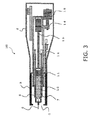
- the drug syringe mounting component 6 itself is configured so as to be able to move back and forth with respect to the injection needle let-in/let-out opening 5. More specifically, a bolt 17 is inserted into a female thread 16 provided to the rear of the drug syringe mounting component 6, and a needle deployment/retraction drive motor 18 is attached to this bolt 17. The drive provided by the needle deployment/retraction drive motor 18 causes the drug syringe mounting component 6 itself to move to the injection needle let-in/let-out opening 5 side as shown in FIG. 3 . As a result, the injection needle 9 sticks out from the injection needle let-in/let-out opening 5. As will be discussed below, the air bleed operation and the injection of the drug 10 are carried out in a state in which the injection needle 9 protrudes from the injection needle let-in/let-out opening 5.
- a number of switches are further housed in the holder 2 of the main body case 1.
- a distal end cap detection switch 20 is disposed toward the distal end of the holder 2.
- the distal end cap detection switch 20 is attached to the rear end of an operating rod 19 provided to the outer periphery of the drug syringe mounting component 6.
- the controller 23 discussed below
- a syringe cover detection switch 22 is disposed in the drug syringe mounting component 6.
- the syringe cover detection switch 22 is attached to the rear end of an operating rod 21 provided inside the drug syringe mounting component 6.
- the operating rod 21 is pushed to the rear end side by the syringe cover 8, and this actuates the syringe cover detection switch 22, which causes the controller 23 (discussed below) to detect the mounting of the syringe cover 8.
- the controller 23 is disposed around the outer periphery of the drug syringe mounting component 6, and controls the operation of the various electrical parts of the drug injection device 100.
- the acceleration sensor 24 is connected to the controller 23. That is, the acceleration sensor 24 is disposed at a place that is away from the center of gravity of the main body case 1. Consequently, the acceleration sensor 24 can more properly detect acceleration with respect to this main body case 1.
- the acceleration sensor 24 is a three-dimensional acceleration sensor, for example.
- a three-dimensional acceleration sensor is suited to the detection of vibration or the detection of falling, as discussed below. If only the inclination of the device main body is to be detected, for example, then either a three-dimensional acceleration sensor or a two-dimensional acceleration sensor may be used.
- FIG. 4 is a control block diagram schematically illustrating the electrical configuration of the drug injection device 100.
- the controller 23 is a control circuit made up of a microprocessor or the like, for example.
- the rechargeable battery 30 shown in FIG. 4 is connected to the controller 23 and other electrically driven parts. The state of electrical connection between this rechargeable battery 30 and the other electrically driven parts is omitted from the drawings for the sake of simplicity.
- the controller 23 includes a central processing unit 31, a ROM 32, and a determination component 33.
- the central processing unit 31 controls the operation of the various blocks shown in FIG. 4 .
- the program that executes this operational control is written to the ROM 32.
- the determination component 33 connected to the central processing unit 31 is also connected to a memory 33A and the acceleration sensor 24.
- the memory 33A stores first and second set values detected by the acceleration sensor 24.
- the determination component 33 is designed to compare the acceleration detected by the acceleration sensor 24 with the first and second set values, and control various operations.
- a motor driver circuit 34 is connected to the piston drive motor 14 and the needle deployment/retraction drive motor 18, and a current detection circuit 35 is connected to this motor driver circuit 34. Further, a sounder 35 and a vibrator 36 for issuing warnings are connected to the controller 23.
- FIG. 5 is a flowchart of the control during the air bleed operation of the drug injection device 100. We will assume a state in which the drug syringe 7 has already been mounted in the drug syringe mounting component 6 as shown in FIG. 2 .
- Step S1 When the air bleed button 26 ( FIGS. 1 and 4 ) is pressed by the user, this is detected by the controller 23.
- Step S2 The determination component 33 of the controller 23 uses the acceleration sensor 24 to perform abnormal vibration detection.
- An abnormal vibration here is a state in which hand shake is occurring, for example.
- the flow proceeds to step S13, this abnormality is displayed (such as a display of "abnormal ending") on the display component 29 ( FIGS. 1 and 4 ), and the operation is ended at step S14.
- Abnormal vibration detection is performed as follows.
- the controller 23 determines whether or not the value indicating acceleration detected by the acceleration sensor 24 exceeds a first set value (specific value) stored in the memory 33A (or is at least the first set value), and, if the value exceeds, determines that there is abnormal vibration.
- Step S3 Needle deployment is begun if no abnormal vibration was detected in step S2.
- Needle deployment here is an operation in which the injection needle 9 is pushed out from the injection needle let-in/let-out opening 5, as shown in FIG. 3 . More specifically, the needle deployment/retraction drive motor 18 is driven at a command from the controller 23, the drug syringe mounting component 6 is moved to the injection needle let-in/let-out opening 5 side, and the injection needle 9 is pushed out through the injection needle let-in/let-out opening 5.
- Step S4 During this needle deployment operation, the determination component 33 uses the acceleration sensor 24 to perform abnormal vibration detection. If abnormal vibration is detected, the flow proceeds to step S12, and need retraction is executed.
- Needle retraction here is an operation in which the injection needle 9 is pulled back through the injection needle let-in/let-out opening 5 to inside the distal end cap 3. More specifically, the needle deployment/retraction drive motor 18 is rotated in the opposite direction from that during needle deployment at a command from the controller 23, and the injection needle 9 is pulled along with the drug syringe mounting component 6 back through the injection needle let-in/let-out opening 5 to inside the distal end cap 3 as shown in FIG. 2 . Here again, the operation is halted in step S14 via step S13.
- Step S5 On the other hand, if no abnormal vibration is detected in step S4, an air bleed operation is begun.
- the "Air bleed operation” here means an operation for purging air from the drug syringe 7 and the injection needle 9. More specifically, the piston drive motor 14 is driven at a command from the controller 23 from a state in which the injection needle 9 is protruding from the injection needle let-in/let-out opening 5 as shown in FIG. 3 , and the rubber seal 11 is pushed in by the piston 12 by a specific amount to the injection needle let-in/let-out opening 5 side. Consequently, a specific amount of the drug 10 is ejected from the injection needle 9, and air is purged from the drug syringe 7 and the injection needle 9.
- the amount of movement of the piston 12 here is controlled by controlling the amount of rotation of the piston drive motor 14 using the encoder 15.
- Step S6 During this air bleed operation, the determination component 33 also performs abnormal vibration detection with the acceleration sensor 24. If abnormal vibration is detected, the flow proceeds to step S11, and the air bleed operation is halted. Then, the operation is ended via steps S12, S13, and S14.
- Step S7 If no abnormal vibration is detected in step S6, the air bleed operation is concluded.
- Step S8 Upon conclusion of the air bleed operation, just as in step S12, needle retraction is executed at a command from the controller 23, and the drug injection device 100 goes from the state shown in FIG. 3 to that in FIG. 2 .
- Step S9 The fact that the air bleed operation has been concluded is displayed on the display component 29.
- Step S10 The operation is ended.
- Step S11 As mentioned above, if abnormal vibration is detected in step S6, the air bleed operation is halted.
- Step S12 As discussed above, needle retraction is executed if abnormal vibration is detected in step S4, or after the air bleed operation has been halted in step S11.
- Step S13 As discussed above, the display component 29 ( FIG. 1 ) displays an abnormality (such as a display of "abnormal ending") if abnormal vibration is detected in step S2, or after the needle retraction operation in step S12.
- an abnormality such as a display of "abnormal ending"
- Step S14 The operation is ended.
- FIG. 6 is a flowchart of the control during the operation in which the drug injection device 100 injects the drug 10 into a patient.
- Step S15 The drug injection button 27 ( FIGS. 1 and 4 ) is pressed by the user, and this is detected by the controller 23.
- Step S16 The determination component 33 of the controller 23 uses the acceleration sensor 24 to perform abnormal vibration detection.
- "Abnormal vibration” is a state in which hand shake is occurring, for example.
- the flow proceeds to step S27, and a display recommending that the operation be performed again (such as "Please inject again") is shown on the display component 29 ( FIGS. 1 and 4 ).
- the operation is then ended at step S28.
- Step S17 If abnormal vibration is not detected in step S16, the needle deployment operation is begun.
- Needle deployment here is an operation in which the injection needle 9 is pushed out from the injection needle let-in/let-out opening 5 as shown in FIG. 3 , and as discussed above, the drug syringe mounting component 6 is moved to the injection needle let-in/let-out opening 5 side by the needle deployment/retraction drive motor 18 at a command from the controller 23.
- step S17 the injection needle 9 is moved toward the body, and the injection needle 9 is plunged into the body.
- Step S18 During this needle deployment operation, the determination component 33 uses the acceleration sensor 24 to perform abnormal vibration detection. If abnormal vibration is detected, the flow proceeds to step S30, and needle retraction is executed.
- needle retraction here is an operation in which the injection needle 9 is pulled back through the injection needle let-in/let-out opening 5 to inside the distal end cap 3 as shown in FIG. 2 . More specifically, the needle deployment/retraction drive motor 18 is rotated in the opposite direction from that during needle deployment at a command from the controller 23, and the injection needle 9 is pulled along with the drug syringe mounting component 6 back through the injection needle let-in/let-out opening 5 to inside the distal end cap 3 as shown in FIG. 2 .
- Step S19 If no abnormal vibration is detected in step S18, the controller 23 begins the injection of the drug 10.
- the injection of the drug 10 here is an operation in which, as shown in FIG. 3 , the piston drive motor 14 is driven at a command from the controller 23 in a state in which the injection needle 9 is sticking out from the injection needle let-in/let-out opening 5, and the rubber seal 11 is pushed in by the piston 12 by a specific amount to the injection needle let-in/let-out opening 5 side. As a result, a specific amount of the drug 10 is injected from the injection needle 9 into the body.
- the amount of movement of the piston 12 here is controlled by controlling the amount of rotation of the piston drive motor 14 using the encoder 15. This movement amount is recorded to the memory 33A in FIG. 4 by a physician, and this sets the amount of drug 10 to be injected each time for each user (injection amount).
- Step S20 During this drug injection operation, the determination component 33 uses the acceleration sensor 24 to perform abnormal vibration detection. If abnormal vibration is detected, the flow proceeds to step S29 and the injection operation is halted. At the point when the injection operation is halted in step S29, the injection needle 9 is in a state of having been inserted into the body. Therefore, the needle retraction operation of the next step S30 is not begun right away, and instead the movement of the piston 12 and the drug syringe mounting component 6 is stopped for six seconds (holding operation), for example, and when it is judged that the drug 10 has penetrated into the body, the needle retraction operation is begun, and the injection needle 9 is pulled out of the body. After this, the operation is ended via steps S31 and S32.
- Step S21 If no abnormal vibration is detected in step S20, the injection operation is concluded.
- Step S22 Just as in step S29, movement of the piston 12 and the drug syringe mounting component 6 is stopped for six seconds (holding operation), for example. This allows the drug 10 to penetrate into the body without fail.
- Step S23 During this holding operation, abnormal vibration detection is performed with the acceleration sensor 24, and if abnormal vibration is detected, the operation is ended via steps S30, S31, and S32.
- Step S24 If no abnormal vibration is detected in step S23, the controller 23 retracts the injection needle 9 into the distal end cap 3 so that the state changes from that in FIG. 3 to that in FIG. 2 , and this pulls the injection needle 9 out of the body.
- Step S25 The controller 23 displays on the display component 29 the fact that the injection of the drug 10 has been concluded.
- Step 526 The operation is ended.
- Step S27 As discussed above, if no abnormal vibration is detected in step S16, a display recommending that the operation be performed again (such as "Please inject again") is shown on the display component 29 ( FIGS. 1 and 4 ).
- Step S28 The operation is ended.
- Step S29 As discussed above, if no abnormal vibration is detected in step S20, the injection operation is halted.
- Step S30 As discussed above, if abnormal vibration is detected in step S18 or step S23, or if the injection operation is halted in step S29, then the needle retraction operation is executed.
- Step S31 A display indicating an abnormality (such as a display of "abnormal ending") is shown on the display component 29 ( FIG. 1 ).
- Step S32 The operation is ended.
- FIG. 7 shows the operation in periodic monitoring by the drug injection device 100.
- Step S33 Periodic monitoring is performed by the determination component 33 of the controller 23.
- the periodic monitoring is performed both in an OFF state in which the power button 25 has not been pressed, and in an ON state in which the power button 25 has been pressed.
- Step S34 The determination component 33 uses the acceleration sensor 24 to perform drop detection. "Drop detection” here is to detect with the acceleration sensor 24 that a large acceleration has been applied.
- a second set value is also stored in the memory 33A shown in FIG. 4 .
- drop detection it is determined that the device has been dropped if an acceleration that is over a second set value (or at least a second set value) is detected.
- the determination component 33 determines whether or not the acceleration sensor 24 has detected an acceleration that is over the first set value in the memory 33A, and determines that there is abnormal vibration if this value has been exceeded. On the other hand, in drop detection, the determination component 33 determines whether or not acceleration has been detected that exceeds a second set value that is greater than the first set value, and determines that the device has been dropped if this value is exceeded.
- Step S35 If a drop is detected in step S34, drop information is stored in the memory 33A at a command from the controller 23, and a drop flag is switched on.
- Step S36 The flow goes back to step S33, and periodic monitoring is continued.
- Step S37 If no drop was detected in step S34, the flow goes back to step S33, and periodic monitoring is continued.
- FIG. 8 shows the operation of the drug injection device 100 when the power is on.
- Step S38 The controller 23 detects that the power button 25 ( FIGS. 1 and 4 ) has been pressed.
- Step S39 The determination component 33 of the controller 23 determines whether the drop flag in the memory 33A ( FIG. 4 ) is on or off (whether or not a flag is active). If the drop flag is off, that is, if there is no drop, the flow proceeds to step S40. If the drop flag is on, that is, if there is a drop, the flow proceeds to step S41.
- Step S40 If it is determined in step S39 that there was no drop, the flow proceeds to the next processing.
- the "next processing” is the processing shown in FIGS. 5 and 6 , for example.
- Step S41 On the other hand, if it is determined in step S39 that there was a drop, then a display indicating that the device has been dropped, and a display recommending that the device be serviced (such as a display of "Product has been dropped; send for repair") are made on the display component 29 shown in FIG. 1 .
- Step S42 The operation is ended.
- the drug injection device 100 pertaining to this embodiment comprises the main body case 1 having the injection needle let-in/let-out opening 5, the drug syringe mounting component 6 provided in the main body case 1, the piston 12 provided movably with respect to the drug syringe mounting component 6, the piston drive motor 14 that drives the piston 12, the controller 23 that is electrically connected to the piston drive motor 14, and the acceleration sensor 24 that is electrically connected to the controller 23.
- This constitution allows the drug to be injected properly.
- any abnormal operation of the main body case 1, such as hand shake, can be detected by the acceleration sensor 24.
- the injection of the drug can be carried out properly by controlling the operation of the drug injection device 100 on the basis of this detection of abnormal operation.
- the acceleration sensor 24 is installed at a position that is away from the center of gravity of the main body case 1, and this affords better detection of acceleration with respect to the main body case 1.
- the controller 23 detects through the acceleration sensor 24 an acceleration that exceeds a first set value (or that is at least the first set value), then movement of the piston 12 to the injection needle let-in/let-out opening side is stopped, and this makes the drug injection device 100 safer to use.
- the drive mechanism 18 is provided for driving the drug syringe mounting component 6, and if the acceleration sensor 24 detects an acceleration that is at least the first set value, the controller 23 stops the drug syringe mounting component 6 from moving to the injection needle let-in/let-out opening side, or retracts the drug syringe mounting component 6 in a direction away from the injection needle let-in/let-out opening 5. This makes the drug injection device 100 safer to use.
- the drug syringe mounting component 6 is retracted away from the injection needle let-in/let-out opening 5, and this makes the drug injection device 100 even safer to use.
- drop information is stored and operation is performed according to whether or not there is drop information, and this makes the drug injection device 100 even safer to use.
- FIG. 9 is a modification of the method for controlling the air bleed operation of the drug injection device 100, and is a flowchart of the control operation when the acceleration sensor has a device inclination detection function in addition to the above-mentioned abnormal vibration detection function.
- the acceleration sensor can be a three-dimensional acceleration sensor just as in the above embodiment, but if only the inclination of the device main body is to be detected, for example, then either a three-dimensional acceleration sensor or a two-dimensional acceleration sensor may be used.
- Step S51 When the user presses the air bleed button 26 ( FIGS. 1 and 4 ), this is detected by the controller 23 (see FIG. 4 ), and an air bleed operation is begun.
- Step S52 The determination component 33 of the controller 23 uses the acceleration sensor 24 (see FIGS. 2 and 4 ) to perform abnormal vibration detection.
- the "abnormal vibration” here is a state in which hand shake is occurring, for example. If abnormal vibration has been detected, the flow proceeds to step S66, and a display indicating an abnormality (such as a display of "abnormal ending") is shown on the display component 29 ( FIGS. 1 and 4 ). The operation is then ended in step S67.
- the abnormal vibration detection here is carried out as follows.
- the determination component 33 determines whether or not the value indicating acceleration detected by the acceleration sensor 24 exceeds a first set value (specific value) stored in the memory 33A (or is at least the first set value), and if this value is exceeded, it is determined that there is abnormal vibration.
- Step S53 The determination component 33 of the controller 23 further performs device inclination detection with the acceleration sensor 24.
- inclination detection refers to confirming that the device is vertically oriented by determining the inclination of the device main body with respect to a vertical line, in which the up direction is the direction of injecting into the user's skin, in order to execute the air bleed operation without fail, for example.
- step S66 a display indicating an abnormality (such as a display of "abnormal ending") is shown on the display component 29 ( FIGS. 1 and 4 ). The operation is then ended in step S67.
- the inclination detection for the device main body is carried out as follows.
- the determination component 33 determines whether or not a value indicating the inclination angle detected by the acceleration sensor 24 exceeds a third set value (specific value) stored in the memory 33A (or is at least the third set value), and if this value is exceeded, it is determined that the inclination of the device main body is abnormal.
- the third set value can be preset in a memory or the like, and is a set value with a range of ⁇ 45 degrees with respect to the vertical direction, for example.
- a set value with a range of ⁇ 30 degrees is even better.
- Inclination of the main body can be detected more accurately by performing the inclination detection after the abnormal vibration detection.
- Step S54 If no abnormal vibration is detected in step S52, and no abnormal inclination of the device main body is detected in step S53, needle deployment is begun.
- needle deployment is an operation in which the injection needle 9 is pushed out from the injection needle let-in/let-out opening 5 as shown in FIG. 3 . More specifically, the needle deployment/retraction drive motor 18 is driven at a command from the controller 23, the drug syringe mounting component 6 is moved to the injection needle let-in/let-out opening 5 side, and the injection needle 9 is pushed out from the injection needle let-in/let-out opening 5.
- Step S55 During this needle deployment operation, the determination component 33 uses the acceleration sensor 24 to perform abnormal vibration detection. If abnormal vibration is detected, the flow proceeds to step S65, and need retraction is executed.
- Needle retraction here is an operation in which the injection needle 9 is pulled back through the injection needle let-in/let-out opening 5 to inside the distal end cap 3, as shown in FIG. 2 . More specifically, the needle deployment/retraction drive motor 18 is rotated in the opposite direction from that during needle deployment at a command from the controller 23, and the injection needle 9 is pulled along with the drug syringe mounting component 6 back through the injection needle let-in/let-out opening 5 to inside the distal end cap 3 as shown in FIG. 2 . Here again, the operation is halted in step S67 via step S66.
- Step S56 Furthermore, during the needle deployment operation, the determination component 33 performs abnormal inclination detection for the device main body with the acceleration sensor 24. If abnormal inclination is detected, the flow proceeds to step S65, and needle retraction is performed. Here again, the operation is halted in step S67 via step S66.
- Step S57 On the other hand, if no abnormal vibration is detected in step S55, and no abnormal inclination of the device main body is detected in step S56, an air bleed operation is begun.
- the "Air bleed operation " here is an operation in which air is purged from the drug syringe 7 and the injection needle 9. More specifically, as shown in FIG. 3 , from a state in which the injection needle 9 is protruding from the injection needle let-in/let-out opening 5, the piston drive motor 14 is driven at a command from the controller 23, and the rubber seal 11 is pushed in by the piston 12 by a specific amount to the injection needle let-in/let-out opening 5 side. Consequently, a specific amount of the drug 10 is ejected from the injection needle 9, and the air is purged from the drug syringe 7 and the injection needle 9.
- the amount of movement of the piston 12 here is controlled by controlling the amount of rotation of the piston drive motor 14 using the encoder 15.
- Step S58 Also during this air bleed operation, the determination component 33 performs abnormal vibration detection with the acceleration sensor 24. If abnormal vibration is detected, the flow proceeds to step S64, and the air bleed operation is halted. The operation is then ended via steps S65, S66, and S67.
- Step S59 Also during this air bleed operation, the determination component 33 performs abnormal inclination detection for the device main body with the acceleration sensor 24. If abnormal inclination is detected, the flow proceeds to step S64, and the air bleed operation is halted. The operation is then ended via steps S65, S66, and S67.
- Step S60 If no abnormal vibration is detected in step S58, and no abnormal inclination of the device main body is detected in step S59, the air bleed operation is concluded.
- Step S61 Upon conclusion of the air bleed operation, needle retraction is performed at a command from the controller 23 just as in step S65, and the drug injection device 100 changes from the state shown in FIG. 3 to that in FIG. 2 .
- Step 562 The fact that the air bleed operation has been concluded is displayed on the display component 29.
- Step S63 The operation is ended.
- Step S64 As mentioned above, if abnormal vibration is detected in step S58, or if abnormal inclination of the device main body is detected in step S59, the air bleed operation is halted.
- Step S65 As discussed above, needle retraction is executed if abnormal vibration is detected in step S55, or if abnormal inclination of the device main body is detected in step S56, or after the air bleed operation has been halted in step S64.
- Step S66 As discussed above, the display component 29 ( FIG. 1 ) displays an abnormality (such as a display of "abnormal ending") if abnormal vibration is detected in step S52, or if abnormal inclination of the device main body is detected in step S53, or after needle retraction in step S65.
- an abnormality such as a display of "abnormal ending"
- Step S67 The operation is ended.
- the present invention is useful as a drug injection device such as a syringe.
Abstract
Description
- The present invention relates to a drug injection device.
- A conventional drug injection device has a main body case, an injection needle let-in/let-out opening that is an opening for letting an injection needle in and out of the main body case, a drug syringe mounting component that is provided inside the main body case and in which a drug syringe is mounted, a piston that is able to move with respect to this drug syringe mounting component, a drive mechanism that drives the piston, and a control circuit that is electrically connected to this drive mechanism. With this drug injection device, when the piston is moved so that sealing rubber within the drug syringe mounting component is pushed, the drug is automatically injected into the patient's body through an injection needle mounted at the distal end side of the drug syringe (see, for example, Patent Literature 1).
- Patent Literature 1: Kohyo (Japanese Unexamined Patent Publication) No.
H11-513586 - However, the injection of the drug is sometimes not carried out properly with a conventional drug injection device. For example, if the user's hand should shake for some reason during drug injection, then the drug cannot be properly injected at the targeted site on the body.
- In view of this, it is an object of the present invention to provide a drug injection device with which the injection of a drug can be carried out properly.
- The drug injection device pertaining to the present invention comprises a main body case, a drug syringe mounting component, a piston, a drive mechanism, a controller, and an acceleration sensor. The main body case has an injection needle let-in/let-out opening. The drug syringe mounting component is provided inside the main body case, and allows a drug syringe to be mounted therein. The piston is movable with respect to the drug syringe mounting component. The drive mechanism drives the piston. The controller is electrically connected to the drive mechanism. The acceleration sensor is electrically connected to the controller.
- As mentioned above, with the drug injection device of the present invention, abnormal operation of the main body case due to, for example, hand shake, can be detected by the acceleration sensor, so the injection of a drug can be carried out properly.
-
-
FIG. 1 is an oblique view of the drug injection device pertaining to an embodiment of the present invention; -
FIG. 2 is a cross section of this drug injection device; -
FIG. 3 is a cross section of this drug injection device; -
FIG. 4 is a control block diagram schematically illustrating the electrical configuration of this drug injection device; -
FIG. 5 is a flowchart of the operation control in this drug injection device; -
FIG. 6 is a flowchart of the operation control in this drug injection device; -
FIG. 7 is a flowchart of the operation control in this drug injection device; -
FIG. 8 is a flowchart of the operation control in this drug injection device; and -
FIG. 9 is a flowchart of the operation control in a modification example of this drug injection device. - The
drug injection device 100 pertaining to an embodiment of the present invention will now be described through reference to the appended drawings. - The
drug injection device 100 shown inFIG. 1 comprises amain body case 1. Themain body case 1 is made up of aholder 2 and a distal end cap 3 attached on the distal end side, which is a drug injection side of theholder 2. - The distal end cap 3 is configured such that it can be attached to and removed from the
holder 2. Also, the distal end cap 3 is provided with acheck window 4 on its outer peripheral part. The distal end cap 3 is further provided on its distal end side with an injection needle let-in/let-out opening 5 for letting an injection needle in and out of the distal end cap 3, as shown inFIG. 2 . - The
holder 2 is provided with various operating buttons on its outer peripheral part. More specifically, apower button 25 is provided at the rear end of theholder 2, and anair bleed button 26, adrug injection button 27, and astop button 28 are provided on the outer periphery of theholder 2. These operating buttons are connected to acontroller 23 as discussed below. The user presses these buttons to execute various operations of the drug injection device 100 (discussed below). Theholder 2 also has adisplay component 29 on its outer peripheral part, and the operating state of thedrug injection device 100, notifications to the user, and so forth are displayed as discussed below. - As shown in
FIG. 2 , thedrug injection device 100 comprises inside the holder 2 a drug syringe mounting component 6 (on the distal end cap 3 side), a piston 12, a piston drive motor 14 (drive mechanism), thecontroller 23, and an acceleration sensor 24 (such as a three-dimensional acceleration sensor). - A
drug syringe 7 is housed in the drugsyringe mounting component 6. After thedrug syringe 7 has been put in place, the outer periphery of thedrug syringe 7 is covered with asyringe cover 8. - As shown in
FIG. 2 , thedrug syringe 7 mounted in the drugsyringe mounting component 6 has an injection needle 9 mounted on its distal end side. The interior of thedrug syringe 7 is filled with adrug 10 at a pharmaceutical manufacturer or the like. Arubber seal 11 is mounted at the rear end opening of thedrug syringe 7.
The piston 12 is disposed so that it can move back and forth inside the drugsyringe mounting component 6 facing therubber seal 11. Abolt 13 is inserted from the rear end side of the piston 12 (the opposite side from the drug injection side) all the way into the piston 12. - The
piston drive motor 14 is attached on the rear end side of thebolt 13, and rotationally drives thebolt 13. Rotation of thebolt 13 causes the male threads around the outer periphery of thebolt 13 to spirally mesh with female threads provided inside the piston 12, and the piston 12 pushes therubber seal 11 forward, that is, to the drug injection side. As a result of this operation, thedrug 10 flows out of the injection needle 9. Also, anencoder 15 is connected to thepiston drive motor 14. Rotation of thepiston drive motor 14 is detected by theencoder 15, and this allows the amount of movement of the piston 12 to be detected. - The drug
syringe mounting component 6 itself is configured so as to be able to move back and forth with respect to the injection needle let-in/let-out opening 5. More specifically, abolt 17 is inserted into a female thread 16 provided to the rear of the drugsyringe mounting component 6, and a needle deployment/retraction drive motor 18 is attached to thisbolt 17. The drive provided by the needle deployment/retraction drive motor 18 causes the drugsyringe mounting component 6 itself to move to the injection needle let-in/let-out opening 5 side as shown inFIG. 3 . As a result, the injection needle 9 sticks out from the injection needle let-in/let-out opening 5. As will be discussed below, the air bleed operation and the injection of thedrug 10 are carried out in a state in which the injection needle 9 protrudes from the injection needle let-in/let-out opening 5. - A number of switches are further housed in the
holder 2 of themain body case 1. - More specifically, a distal end
cap detection switch 20 is disposed toward the distal end of theholder 2. The distal endcap detection switch 20 is attached to the rear end of an operatingrod 19 provided to the outer periphery of the drugsyringe mounting component 6. When the distal end cap 3 is mounted to the distal end of theholder 2, the operatingrod 19 is pushed to the rear end side, and the distal endcap detection switch 20 is actuated, which causes the controller 23 (discussed below) to detect the mounting of the distal end cap 3. - Also, a syringe
cover detection switch 22 is disposed in the drugsyringe mounting component 6. The syringecover detection switch 22 is attached to the rear end of an operatingrod 21 provided inside the drugsyringe mounting component 6. The operatingrod 21 is pushed to the rear end side by thesyringe cover 8, and this actuates the syringecover detection switch 22, which causes the controller 23 (discussed below) to detect the mounting of thesyringe cover 8. - The
controller 23 is disposed around the outer periphery of the drugsyringe mounting component 6, and controls the operation of the various electrical parts of thedrug injection device 100. - Further, the
acceleration sensor 24 is connected to thecontroller 23. That is, theacceleration sensor 24 is disposed at a place that is away from the center of gravity of themain body case 1. Consequently, theacceleration sensor 24 can more properly detect acceleration with respect to thismain body case 1. - Here, the
acceleration sensor 24 is a three-dimensional acceleration sensor, for example. A three-dimensional acceleration sensor is suited to the detection of vibration or the detection of falling, as discussed below. If only the inclination of the device main body is to be detected, for example, then either a three-dimensional acceleration sensor or a two-dimensional acceleration sensor may be used. -
FIG. 4 is a control block diagram schematically illustrating the electrical configuration of thedrug injection device 100. Thecontroller 23 is a control circuit made up of a microprocessor or the like, for example. Therechargeable battery 30 shown inFIG. 4 is connected to thecontroller 23 and other electrically driven parts. The state of electrical connection between thisrechargeable battery 30 and the other electrically driven parts is omitted from the drawings for the sake of simplicity. - The
controller 23 includes acentral processing unit 31, aROM 32, and adetermination component 33. Thecentral processing unit 31 controls the operation of the various blocks shown inFIG. 4 . The program that executes this operational control is written to theROM 32. Thedetermination component 33 connected to thecentral processing unit 31 is also connected to amemory 33A and theacceleration sensor 24. - The
memory 33A, as discussed below, stores first and second set values detected by theacceleration sensor 24. Thedetermination component 33 is designed to compare the acceleration detected by theacceleration sensor 24 with the first and second set values, and control various operations. - A
motor driver circuit 34 is connected to thepiston drive motor 14 and the needle deployment/retraction drive motor 18, and acurrent detection circuit 35 is connected to thismotor driver circuit 34. Further, a sounder 35 and avibrator 36 for issuing warnings are connected to thecontroller 23. - The various operational controls of the
drug injection device 100 having the above electrical configuration will now be described through reference to a flowchart. -
FIG. 5 is a flowchart of the control during the air bleed operation of thedrug injection device 100. We will assume a state in which thedrug syringe 7 has already been mounted in the drugsyringe mounting component 6 as shown inFIG. 2 . - Step S1: When the air bleed button 26 (
FIGS. 1 and4 ) is pressed by the user, this is detected by thecontroller 23. - Step S2: The
determination component 33 of thecontroller 23 uses theacceleration sensor 24 to perform abnormal vibration detection. An abnormal vibration here is a state in which hand shake is occurring, for example. When abnormal vibration is detected, the flow proceeds to step S13, this abnormality is displayed (such as a display of "abnormal ending") on the display component 29 (FIGS. 1 and4 ), and the operation is ended at step S14. - Abnormal vibration detection is performed as follows. The
controller 23 determines whether or not the value indicating acceleration detected by theacceleration sensor 24 exceeds a first set value (specific value) stored in thememory 33A (or is at least the first set value), and, if the value exceeds, determines that there is abnormal vibration. - Step S3: Needle deployment is begun if no abnormal vibration was detected in step S2. "Needle deployment" here is an operation in which the injection needle 9 is pushed out from the injection needle let-in/let-out
opening 5, as shown inFIG. 3 . More specifically, the needle deployment/retraction drive motor 18 is driven at a command from thecontroller 23, the drugsyringe mounting component 6 is moved to the injection needle let-in/let-outopening 5 side, and the injection needle 9 is pushed out through the injection needle let-in/let-outopening 5. - Step S4: During this needle deployment operation, the
determination component 33 uses theacceleration sensor 24 to perform abnormal vibration detection. If abnormal vibration is detected, the flow proceeds to step S12, and need retraction is executed. "Needle retraction" here is an operation in which the injection needle 9 is pulled back through the injection needle let-in/let-outopening 5 to inside the distal end cap 3. More specifically, the needle deployment/retraction drive motor 18 is rotated in the opposite direction from that during needle deployment at a command from thecontroller 23, and the injection needle 9 is pulled along with the drugsyringe mounting component 6 back through the injection needle let-in/let-outopening 5 to inside the distal end cap 3 as shown inFIG. 2 . Here again, the operation is halted in step S14 via step S13. - Step S5: On the other hand, if no abnormal vibration is detected in step S4, an air bleed operation is begun. The "Air bleed operation" here means an operation for purging air from the
drug syringe 7 and the injection needle 9. More specifically, thepiston drive motor 14 is driven at a command from thecontroller 23 from a state in which the injection needle 9 is protruding from the injection needle let-in/let-outopening 5 as shown inFIG. 3 , and therubber seal 11 is pushed in by the piston 12 by a specific amount to the injection needle let-in/let-outopening 5 side. Consequently, a specific amount of thedrug 10 is ejected from the injection needle 9, and air is purged from thedrug syringe 7 and the injection needle 9. - The amount of movement of the piston 12 here is controlled by controlling the amount of rotation of the
piston drive motor 14 using theencoder 15. - Step S6: During this air bleed operation, the
determination component 33 also performs abnormal vibration detection with theacceleration sensor 24. If abnormal vibration is detected, the flow proceeds to step S11, and the air bleed operation is halted. Then, the operation is ended via steps S12, S13, and S14. - Step S7: If no abnormal vibration is detected in step S6, the air bleed operation is concluded.
- Step S8: Upon conclusion of the air bleed operation, just as in step S12, needle retraction is executed at a command from the
controller 23, and thedrug injection device 100 goes from the state shown inFIG. 3 to that inFIG. 2 . - Step S9: The fact that the air bleed operation has been concluded is displayed on the
display component 29. - Step S10: The operation is ended.
- Step S11: As mentioned above, if abnormal vibration is detected in step S6, the air bleed operation is halted.
- Step S12: As discussed above, needle retraction is executed if abnormal vibration is detected in step S4, or after the air bleed operation has been halted in step S11.
- Step S13: As discussed above, the display component 29 (
FIG. 1 ) displays an abnormality (such as a display of "abnormal ending") if abnormal vibration is detected in step S2, or after the needle retraction operation in step S12. - Step S14: The operation is ended.
-
FIG. 6 is a flowchart of the control during the operation in which thedrug injection device 100 injects thedrug 10 into a patient. - Step S15: The drug injection button 27 (
FIGS. 1 and4 ) is pressed by the user, and this is detected by thecontroller 23. - Step S16: The
determination component 33 of thecontroller 23 uses theacceleration sensor 24 to perform abnormal vibration detection. "Abnormal vibration," as mentioned above, is a state in which hand shake is occurring, for example. When abnormal vibration is detected, the flow proceeds to step S27, and a display recommending that the operation be performed again (such as "Please inject again") is shown on the display component 29 (FIGS. 1 and4 ). The operation is then ended at step S28. - Step S17: If abnormal vibration is not detected in step S16, the needle deployment operation is begun. "Needle deployment" here is an operation in which the injection needle 9 is pushed out from the injection needle let-in/let-out
opening 5 as shown inFIG. 3 , and as discussed above, the drugsyringe mounting component 6 is moved to the injection needle let-in/let-outopening 5 side by the needle deployment/retraction drive motor 18 at a command from thecontroller 23. - At this point, the injection needle let-in/let-out
opening 5 of the distal end cap 3 is already being pressed against the site on the body to receive the injection. Thus, in step S17, the injection needle 9 is moved toward the body, and the injection needle 9 is plunged into the body. - Step S18: During this needle deployment operation, the
determination component 33 uses theacceleration sensor 24 to perform abnormal vibration detection. If abnormal vibration is detected, the flow proceeds to step S30, and needle retraction is executed. As discussed above, "needle retraction" here is an operation in which the injection needle 9 is pulled back through the injection needle let-in/let-outopening 5 to inside the distal end cap 3 as shown inFIG. 2 . More specifically, the needle deployment/retraction drive motor 18 is rotated in the opposite direction from that during needle deployment at a command from thecontroller 23, and the injection needle 9 is pulled along with the drugsyringe mounting component 6 back through the injection needle let-in/let-outopening 5 to inside the distal end cap 3 as shown inFIG. 2 . - Step S19: If no abnormal vibration is detected in step S18, the
controller 23 begins the injection of thedrug 10. The injection of thedrug 10 here is an operation in which, as shown inFIG. 3 , thepiston drive motor 14 is driven at a command from thecontroller 23 in a state in which the injection needle 9 is sticking out from the injection needle let-in/let-outopening 5, and therubber seal 11 is pushed in by the piston 12 by a specific amount to the injection needle let-in/let-outopening 5 side. As a result, a specific amount of thedrug 10 is injected from the injection needle 9 into the body. - The amount of movement of the piston 12 here is controlled by controlling the amount of rotation of the
piston drive motor 14 using theencoder 15. This movement amount is recorded to thememory 33A inFIG. 4 by a physician, and this sets the amount ofdrug 10 to be injected each time for each user (injection amount). - Step S20: During this drug injection operation, the
determination component 33 uses theacceleration sensor 24 to perform abnormal vibration detection. If abnormal vibration is detected, the flow proceeds to step S29 and the injection operation is halted. At the point when the injection operation is halted in step S29, the injection needle 9 is in a state of having been inserted into the body. Therefore, the needle retraction operation of the next step S30 is not begun right away, and instead the movement of the piston 12 and the drugsyringe mounting component 6 is stopped for six seconds (holding operation), for example, and when it is judged that thedrug 10 has penetrated into the body, the needle retraction operation is begun, and the injection needle 9 is pulled out of the body. After this, the operation is ended via steps S31 and S32. - Step S21: If no abnormal vibration is detected in step S20, the injection operation is concluded.
- Step S22: Just as in step S29, movement of the piston 12 and the drug
syringe mounting component 6 is stopped for six seconds (holding operation), for example. This allows thedrug 10 to penetrate into the body without fail. - Step S23: During this holding operation, abnormal vibration detection is performed with the
acceleration sensor 24, and if abnormal vibration is detected, the operation is ended via steps S30, S31, and S32. - Step S24: If no abnormal vibration is detected in step S23, the
controller 23 retracts the injection needle 9 into the distal end cap 3 so that the state changes from that inFIG. 3 to that inFIG. 2 , and this pulls the injection needle 9 out of the body. - Step S25: The
controller 23 displays on thedisplay component 29 the fact that the injection of thedrug 10 has been concluded. - Step 526: The operation is ended.
- Step S27: As discussed above, if no abnormal vibration is detected in step S16, a display recommending that the operation be performed again (such as "Please inject again") is shown on the display component 29 (
FIGS. 1 and4 ). - Step S28: The operation is ended.
- Step S29: As discussed above, if no abnormal vibration is detected in step S20, the injection operation is halted.
- Step S30: As discussed above, if abnormal vibration is detected in step S18 or step S23, or if the injection operation is halted in step S29, then the needle retraction operation is executed.
- Step S31: A display indicating an abnormality (such as a display of "abnormal ending") is shown on the display component 29 (
FIG. 1 ). - Step S32: The operation is ended.
-
FIG. 7 shows the operation in periodic monitoring by thedrug injection device 100. - Step S33: Periodic monitoring is performed by the
determination component 33 of thecontroller 23. The periodic monitoring is performed both in an OFF state in which thepower button 25 has not been pressed, and in an ON state in which thepower button 25 has been pressed. - Step S34: The
determination component 33 uses theacceleration sensor 24 to perform drop detection. "Drop detection" here is to detect with theacceleration sensor 24 that a large acceleration has been applied. - In addition to the above-mentioned first set value used for acceleration, a second set value is also stored in the
memory 33A shown inFIG. 4 . In drop detection, it is determined that the device has been dropped if an acceleration that is over a second set value (or at least a second set value) is detected. - That is, in abnormal vibration detection by means of hand shake or the like as discussed above, the
determination component 33 determines whether or not theacceleration sensor 24 has detected an acceleration that is over the first set value in thememory 33A, and determines that there is abnormal vibration if this value has been exceeded. On the other hand, in drop detection, thedetermination component 33 determines whether or not acceleration has been detected that exceeds a second set value that is greater than the first set value, and determines that the device has been dropped if this value is exceeded. - Step S35: If a drop is detected in step S34, drop information is stored in the
memory 33A at a command from thecontroller 23, and a drop flag is switched on. - Step S36: The flow goes back to step S33, and periodic monitoring is continued.
- Step S37: If no drop was detected in step S34, the flow goes back to step S33, and periodic monitoring is continued.
-
FIG. 8 shows the operation of thedrug injection device 100 when the power is on. - Step S38: The
controller 23 detects that the power button 25 (FIGS. 1 and4 ) has been pressed. - Step S39: The
determination component 33 of thecontroller 23 determines whether the drop flag in thememory 33A (FIG. 4 ) is on or off (whether or not a flag is active). If the drop flag is off, that is, if there is no drop, the flow proceeds to step S40. If the drop flag is on, that is, if there is a drop, the flow proceeds to step S41. - Step S40: If it is determined in step S39 that there was no drop, the flow proceeds to the next processing. The "next processing" is the processing shown in
FIGS. 5 and6 , for example. - Step S41: On the other hand, if it is determined in step S39 that there was a drop, then a display indicating that the device has been dropped, and a display recommending that the device be serviced (such as a display of "Product has been dropped; send for repair") are made on the
display component 29 shown inFIG. 1 . - Step S42: The operation is ended.
- As discussed above, the
drug injection device 100 pertaining to this embodiment comprises themain body case 1 having the injection needle let-in/let-outopening 5, the drugsyringe mounting component 6 provided in themain body case 1, the piston 12 provided movably with respect to the drugsyringe mounting component 6, thepiston drive motor 14 that drives the piston 12, thecontroller 23 that is electrically connected to thepiston drive motor 14, and theacceleration sensor 24 that is electrically connected to thecontroller 23. This constitution allows the drug to be injected properly. - Specifically, with this embodiment, since the
acceleration sensor 24 is connected to thecontroller 23, any abnormal operation of themain body case 1, such as hand shake, can be detected by theacceleration sensor 24. The injection of the drug can be carried out properly by controlling the operation of thedrug injection device 100 on the basis of this detection of abnormal operation. - With the
drug injection device 100 pertaining to this embodiment, theacceleration sensor 24 is installed at a position that is away from the center of gravity of themain body case 1, and this affords better detection of acceleration with respect to themain body case 1. - With the
drug injection device 100 pertaining to this embodiment, if thecontroller 23 detects through theacceleration sensor 24 an acceleration that exceeds a first set value (or that is at least the first set value), then movement of the piston 12 to the injection needle let-in/let-out opening side is stopped, and this makes thedrug injection device 100 safer to use. - With the
drug injection device 100 pertaining to this embodiment, thedrive mechanism 18 is provided for driving the drugsyringe mounting component 6, and if theacceleration sensor 24 detects an acceleration that is at least the first set value, thecontroller 23 stops the drugsyringe mounting component 6 from moving to the injection needle let-in/let-out opening side, or retracts the drugsyringe mounting component 6 in a direction away from the injection needle let-in/let-outopening 5. This makes thedrug injection device 100 safer to use. - Also, at this point, after the movement of the drug
syringe mounting component 6 to the injection needle let-in/let-out opening side has been halted for a specific length of time, the drugsyringe mounting component 6 is retracted away from the injection needle let-in/let-outopening 5, and this makes thedrug injection device 100 even safer to use. - With the
drug injection device 100 pertaining to this embodiment, drop information is stored and operation is performed according to whether or not there is drop information, and this makes thedrug injection device 100 even safer to use. - An embodiment of the present invention was given above, but the present invention is not limited to what was given in the above embodiment, and a person skilled in the art will foresee modifications and applications on the basis of the text of this Specification and known technology, all of which is encompassed by the scope for which protection is sought.
- A modification of the method for controlling the air bleed operation will now be given.
-
FIG. 9 is a modification of the method for controlling the air bleed operation of thedrug injection device 100, and is a flowchart of the control operation when the acceleration sensor has a device inclination detection function in addition to the above-mentioned abnormal vibration detection function. Here, the acceleration sensor can be a three-dimensional acceleration sensor just as in the above embodiment, but if only the inclination of the device main body is to be detected, for example, then either a three-dimensional acceleration sensor or a two-dimensional acceleration sensor may be used. - During the control operation in
FIG. 9 , as shown inFIG. 2 , let us assume that thedrug syringe 7 has already been mounted in the drugsyringe mounting component 6. - Step S51: When the user presses the air bleed button 26 (
FIGS. 1 and4 ), this is detected by the controller 23 (seeFIG. 4 ), and an air bleed operation is begun. - Step S52: The
determination component 33 of thecontroller 23 uses the acceleration sensor 24 (seeFIGS. 2 and4 ) to perform abnormal vibration detection. The "abnormal vibration" here is a state in which hand shake is occurring, for example. If abnormal vibration has been detected, the flow proceeds to step S66, and a display indicating an abnormality (such as a display of "abnormal ending") is shown on the display component 29 (FIGS. 1 and4 ). The operation is then ended in step S67. - The abnormal vibration detection here is carried out as follows. The
determination component 33 determines whether or not the value indicating acceleration detected by theacceleration sensor 24 exceeds a first set value (specific value) stored in thememory 33A (or is at least the first set value), and if this value is exceeded, it is determined that there is abnormal vibration. - Step S53: The
determination component 33 of thecontroller 23 further performs device inclination detection with theacceleration sensor 24. Here, "inclination detection" refers to confirming that the device is vertically oriented by determining the inclination of the device main body with respect to a vertical line, in which the up direction is the direction of injecting into the user's skin, in order to execute the air bleed operation without fail, for example. - If this device inclination detection concludes that there is an abnormality, the flow proceeds to step S66, and a display indicating an abnormality (such as a display of "abnormal ending") is shown on the display component 29 (
FIGS. 1 and4 ). The operation is then ended in step S67. - The inclination detection for the device main body is carried out as follows. The
determination component 33 determines whether or not a value indicating the inclination angle detected by theacceleration sensor 24 exceeds a third set value (specific value) stored in thememory 33A (or is at least the third set value), and if this value is exceeded, it is determined that the inclination of the device main body is abnormal. - The third set value can be preset in a memory or the like, and is a set value with a range of ±45 degrees with respect to the vertical direction, for example. A set value with a range of ±30 degrees is even better.
- Inclination of the main body can be detected more accurately by performing the inclination detection after the abnormal vibration detection.
- Step S54: If no abnormal vibration is detected in step S52, and no abnormal inclination of the device main body is detected in step S53, needle deployment is begun. Here, "needle deployment" is an operation in which the injection needle 9 is pushed out from the injection needle let-in/let-out
opening 5 as shown inFIG. 3 . More specifically, the needle deployment/retraction drive motor 18 is driven at a command from thecontroller 23, the drugsyringe mounting component 6 is moved to the injection needle let-in/let-outopening 5 side, and the injection needle 9 is pushed out from the injection needle let-in/let-outopening 5. - Step S55: During this needle deployment operation, the
determination component 33 uses theacceleration sensor 24 to perform abnormal vibration detection. If abnormal vibration is detected, the flow proceeds to step S65, and need retraction is executed. "Needle retraction" here is an operation in which the injection needle 9 is pulled back through the injection needle let-in/let-outopening 5 to inside the distal end cap 3, as shown inFIG. 2 . More specifically, the needle deployment/retraction drive motor 18 is rotated in the opposite direction from that during needle deployment at a command from thecontroller 23, and the injection needle 9 is pulled along with the drugsyringe mounting component 6 back through the injection needle let-in/let-outopening 5 to inside the distal end cap 3 as shown inFIG. 2 . Here again, the operation is halted in step S67 via step S66. - Step S56: Furthermore, during the needle deployment operation, the
determination component 33 performs abnormal inclination detection for the device main body with theacceleration sensor 24. If abnormal inclination is detected, the flow proceeds to step S65, and needle retraction is performed. Here again, the operation is halted in step S67 via step S66. - Step S57: On the other hand, if no abnormal vibration is detected in step S55, and no abnormal inclination of the device main body is detected in step S56, an air bleed operation is begun. The "Air bleed operation " here is an operation in which air is purged from the
drug syringe 7 and the injection needle 9. More specifically, as shown inFIG. 3 , from a state in which the injection needle 9 is protruding from the injection needle let-in/let-outopening 5, thepiston drive motor 14 is driven at a command from thecontroller 23, and therubber seal 11 is pushed in by the piston 12 by a specific amount to the injection needle let-in/let-outopening 5 side. Consequently, a specific amount of thedrug 10 is ejected from the injection needle 9, and the air is purged from thedrug syringe 7 and the injection needle 9. - The amount of movement of the piston 12 here is controlled by controlling the amount of rotation of the
piston drive motor 14 using theencoder 15. - Step S58: Also during this air bleed operation, the
determination component 33 performs abnormal vibration detection with theacceleration sensor 24. If abnormal vibration is detected, the flow proceeds to step S64, and the air bleed operation is halted. The operation is then ended via steps S65, S66, and S67. - Step S59: Also during this air bleed operation, the
determination component 33 performs abnormal inclination detection for the device main body with theacceleration sensor 24. If abnormal inclination is detected, the flow proceeds to step S64, and the air bleed operation is halted. The operation is then ended via steps S65, S66, and S67. - Step S60: If no abnormal vibration is detected in step S58, and no abnormal inclination of the device main body is detected in step S59, the air bleed operation is concluded.
- Step S61: Upon conclusion of the air bleed operation, needle retraction is performed at a command from the
controller 23 just as in step S65, and thedrug injection device 100 changes from the state shown inFIG. 3 to that inFIG. 2 . - Step 562: The fact that the air bleed operation has been concluded is displayed on the
display component 29. - Step S63: The operation is ended.
- Step S64: As mentioned above, if abnormal vibration is detected in step S58, or if abnormal inclination of the device main body is detected in step S59, the air bleed operation is halted.
- Step S65: As discussed above, needle retraction is executed if abnormal vibration is detected in step S55, or if abnormal inclination of the device main body is detected in step S56, or after the air bleed operation has been halted in step S64.
- Step S66: As discussed above, the display component 29 (
FIG. 1 ) displays an abnormality (such as a display of "abnormal ending") if abnormal vibration is detected in step S52, or if abnormal inclination of the device main body is detected in step S53, or after needle retraction in step S65. - Step S67: The operation is ended.
- With the above modification example of the
drug injection device 100, in addition to the detection of abnormal vibration in thedrug injection device 100 by an acceleration sensor, inclination of the device main body is also detected during the air bleed operation, and controlling the operation of thedrug injection device 100 is in this way allows the air bleed operation to be carried out more accurately. - The present invention is useful as a drug injection device such as a syringe.
-
- 1
- main body case
- 2
- holder
- 3
- distal end cap
- 4
- check window
- 5
- injection needle let-in/let-out opening
- 6
- drug syringe mounting component
- 7
- drug syringe
- 8
- syringe cover
- 9
- injection needle
- 10
- drug
- 11
- rubber seal
- 12
- piston
- 13
- bolt
- 14
- piston drive motor (drive mechanism)
- 15
- encoder
- 16
- female thread
- 17
- bolt
- 18
- needle deployment/retraction drive motor (drive mechanism)
- 19
- operating rod
- 20
- distal end cap detection switch
- 21
- operating rod
- 22
- syringe cover detection switch
- 23
- controller
- 24
- acceleration sensor
- 25
- power button
- 26
- air bleed button
- 27
- drug injection button
- 28
- stop button
- 29
- display component
- 30
- rechargeable battery
- 31
- central processing unit
- 32
- ROM
- 33
- determination component
- 33A
- memory
- 34
- motor driver circuit
- 35
- sounder
- 36
- vibrator
- 100
- drug injection device
Claims (8)
- A drug injection device, comprising:a main body case having an injection needle let-in/let-out opening;a drug syringe mounting component provided inside the main body case and configured to mount a drug syringe therein;a piston configured to be movable with respect to the drug syringe mounting component;a drive mechanism configured to drive the piston;a controller electrically connected to the drive mechanism; andan acceleration sensor electrically connected to the controller.
- The drug injection device according to Claim 1,
wherein the acceleration sensor is installed at a position that is away from a center of gravity of the main body case. - The drug injection device according to Claim 1 or 2,
wherein the controller stops the piston from moving toward the injection needle let-in/let-out opening when the acceleration sensor has detected an acceleration of at least a first set value. - The drug injection device according to any of Claims 1 to 3,
further comprising a drive mechanism configured to drive the drug syringe mounting component,
wherein the controller stops the drug syringe mounting component from moving toward the injection needle let-in/let-out opening, or retracts the drug syringe mounting component away from the injection needle let-in/let-out opening, when the acceleration sensor has detected an acceleration of at least a first set value. - The drug injection device according to any of Claims 1 to 4,
wherein the controller stores abnormality information in a memory when the acceleration sensor has detected an acceleration of at least a second set value that is greater than the first set value. - The drug injection device according to Claim 5,
wherein the abnormality information is information indicating the main body case has been dropped. - The drug injection device according to Claim 4,
wherein the controller stops the drug syringe mounting component from moving toward the injection needle let-in/let-out opening for a specific length of time, and then retracts the drug syringe mounting component away from the injection needle let-in/let-out opening, when the acceleration sensor has detected an acceleration of at least a first set value. - The drug injection device according to any of Claims 1 to 7,
wherein the acceleration sensor further detects information about the inclination of the main body case, and
the controller acquires the information about the inclination of the main body case detected by the acceleration sensor, and on the basis of this information, determines whether or not air bleeding is possible and controls the drive mechanism.
Applications Claiming Priority (2)
| Application Number | Priority Date | Filing Date | Title |
|---|---|---|---|
| JP2009050052 | 2009-03-04 | ||
| PCT/JP2010/001380 WO2010100883A1 (en) | 2009-03-04 | 2010-03-01 | Drug infusion device |
Publications (3)
| Publication Number | Publication Date |
|---|---|
| EP2384778A1 true EP2384778A1 (en) | 2011-11-09 |
| EP2384778A4 EP2384778A4 (en) | 2014-10-01 |
| EP2384778B1 EP2384778B1 (en) | 2018-02-28 |
Family
ID=42709451
Family Applications (1)
| Application Number | Title | Priority Date | Filing Date |
|---|---|---|---|
| EP10748483.4A Active EP2384778B1 (en) | 2009-03-04 | 2010-03-01 | Drug injection device with acceleration sensor |
Country Status (5)
| Country | Link |
|---|---|
| US (1) | US8784381B2 (en) |
| EP (1) | EP2384778B1 (en) |
| JP (1) | JP5451741B2 (en) |
| CN (1) | CN102300597B (en) |
| WO (1) | WO2010100883A1 (en) |
Cited By (21)
| Publication number | Priority date | Publication date | Assignee | Title |
|---|---|---|---|---|
| WO2014015239A1 (en) | 2012-07-19 | 2014-01-23 | Asante Solutions, Inc. | Infusion pump system and method |
| EP2799101A4 (en) * | 2011-12-26 | 2015-06-03 | Panasonic Healthcare Holdings Co Ltd | Medicine injection device |
| US9173995B1 (en) | 2014-10-28 | 2015-11-03 | Bayer Healthcare Llc | Self-orienting syringe and syringe interface |
| WO2015110533A3 (en) * | 2014-01-27 | 2015-11-05 | Ucb Biopharma Sprl | Auto-injector |
| US9199033B1 (en) | 2014-10-28 | 2015-12-01 | Bayer Healthcare Llc | Self-orienting syringe and syringe interface |
| EP2777731A4 (en) * | 2011-11-10 | 2016-01-13 | Panasonic Healthcare Holdings Co Ltd | Drug injection device |
| US9757524B2 (en) | 2012-07-30 | 2017-09-12 | Ucb Biopharma Sprl | Auto-injector |
| US9757521B2 (en) | 2012-07-30 | 2017-09-12 | Ucb Biopharma Sprl | Auto-injector |
| US9757513B2 (en) | 2012-07-30 | 2017-09-12 | Ucb Biopharma Sprl | Auto-injector |
| US9764084B2 (en) | 2011-06-02 | 2017-09-19 | Ucb Biopharma Sprl | Auto-injector |
| US9764101B2 (en) | 2012-07-30 | 2017-09-19 | Ucb Biopharma Sprl | Auto-injector |
| US9789254B2 (en) | 2014-01-27 | 2017-10-17 | Ucb Biopharma Sprl | Auto-injector |
| US9821123B2 (en) | 2014-01-27 | 2017-11-21 | Ucb Biopharma Sprl | Auto-injector |
| US9901686B2 (en) | 2008-01-11 | 2018-02-27 | Ucb Biopharma Sprl | Systems and methods for administering medication |
| US10046110B2 (en) | 2013-01-16 | 2018-08-14 | Bayer Pharma Aktiengesellschaft | Lock for drug injection device |
| PL424735A1 (en) * | 2018-03-01 | 2019-09-09 | Copernicus Spółka Z Ograniczoną Odpowiedzialnością | Device for monitoring condition of the applicator injecting pharmaceutical substance and method for monitoring condition of the applicator by means of this device |
| US10792418B2 (en) | 2014-10-28 | 2020-10-06 | Bayer Healthcare Llc | Self-orienting pressure jacket and pressure jacket-to-injector interface |
| US10835674B2 (en) | 2015-11-13 | 2020-11-17 | Bayer Healthcare Llc | Nested syringe assembly |
| US11129934B2 (en) | 2014-10-28 | 2021-09-28 | Bayer Healthcare Llc | Self-orienting pressure jacket and pressure jacket-to-injector interface |
| US11191893B2 (en) | 2018-01-31 | 2021-12-07 | Bayer Healthcare Llc | System and method for syringe engagement with injector |
| WO2024009277A1 (en) * | 2022-07-08 | 2024-01-11 | Novartis Ag | Patient onboarding and autoinjector integration |
Families Citing this family (28)
| Publication number | Priority date | Publication date | Assignee | Title |
|---|---|---|---|---|
| JP5711156B2 (en) | 2009-02-27 | 2015-04-30 | ライフスキャン・インコーポレイテッドLifescan,Inc. | Drug delivery system |
| ES2432316T3 (en) * | 2009-09-26 | 2013-12-02 | Anteis Sa | Assisted injection device |
| ES2444783T3 (en) * | 2011-09-28 | 2014-02-26 | Q-Med Ab | Electronic injector |
| US9358336B2 (en) | 2012-03-27 | 2016-06-07 | Novo Nordisk A/S | Drug delivery device with piston proximity sensing |
| EP2841131A2 (en) | 2012-04-24 | 2015-03-04 | Novo Nordisk A/S | Drug delivery device and method for detection of an end-of-dose condition |
| KR101984021B1 (en) * | 2012-05-01 | 2019-05-30 | 마사노리 사에키 | Perspiration alleviation device |
| WO2014179774A1 (en) * | 2013-05-03 | 2014-11-06 | Becton, Dickinson And Company | Drug delivery device |
| WO2014191355A1 (en) | 2013-05-27 | 2014-12-04 | Novo Nordisk A/S | Drug delivery device and system with pre-set dose feature |
| CN105828856B (en) | 2013-12-17 | 2019-11-05 | 诺和诺德股份有限公司 | Motor-driven medicament delivery device with charging security feature |
| EP3473282B1 (en) | 2013-12-27 | 2021-09-29 | PHC Holdings Corporation | Drug injection device |
| CN106232161A (en) | 2014-05-02 | 2016-12-14 | 诺和诺德股份有限公司 | Telescopic drive arrangement for drug delivery device |
| CN106659852A (en) | 2014-07-09 | 2017-05-10 | 诺和诺德股份有限公司 | Motorized drug delivery device |
| WO2016042076A1 (en) * | 2014-09-18 | 2016-03-24 | Novo Nordisk A/S | Drug delivery device with cartridge centring feature |
| US20170290981A1 (en) | 2014-09-18 | 2017-10-12 | Novo Nordisk A/S | Drug Delivery Device with Piston Driver Distal Feature |
| KR20170097020A (en) | 2014-12-23 | 2017-08-25 | 오토메드 피티와이 리미티드 | Delivery apparatus, system and associated methods |
| JP6668387B2 (en) * | 2015-06-19 | 2020-03-18 | ヤンセン ファーマシューティカ エヌ.ベー. | Apparatus and method for administration and mixing of drugs and training of appropriate techniques therefor |
| EP3192546A1 (en) | 2016-01-12 | 2017-07-19 | Novo Nordisk A/S | Drug delivery device with improved dose accuracy |
| DE102015121409A1 (en) * | 2015-12-09 | 2017-06-14 | Emperra Gmbh E-Health Technologies | Injection device for injecting metered quantities of a liquid therapeutic agent |
| NZ742538A (en) | 2015-12-30 | 2023-06-30 | Ascendis Pharma As | Auto injector with adaptable air-shot mechanism |
| JP7335072B2 (en) | 2015-12-30 | 2023-08-29 | アセンディス ファーマ エー/エス | Auto-injector with spent cartridge detection and related methods |
| WO2017114907A1 (en) | 2015-12-30 | 2017-07-06 | Ascendis Pharma A/S | Auto injector with cartridge retention system |
| HUE060792T2 (en) | 2015-12-30 | 2023-04-28 | Ascendis Pharma As | Auto injector with temperature control |
| US11406760B2 (en) | 2015-12-30 | 2022-08-09 | Ascendis Pharma A/S | Auto injector with charger safety |
| DE102016104101A1 (en) * | 2016-03-07 | 2017-09-07 | Emperra Gmbh E-Health Technologies | Injection device for injecting metered quantities of a liquid therapeutic agent |
| MX2019013691A (en) | 2017-05-23 | 2020-07-14 | Ascendis Pharma As | Auto injector with variable plunger force. |
| JP6920555B2 (en) * | 2017-12-15 | 2021-08-18 | イーライ リリー アンド カンパニー | Drug delivery device with syringe detection system |
| US11672916B2 (en) | 2017-12-28 | 2023-06-13 | Sanofi | Sensor device for attachment to an injection device |
| CN112604086B (en) * | 2020-12-25 | 2021-11-23 | 常熟康信医疗器械有限公司 | Electronic syringe capable of automatically advancing and retreating needle |
Citations (5)
| Publication number | Priority date | Publication date | Assignee | Title |
|---|---|---|---|---|
| WO1997014459A1 (en) * | 1995-10-20 | 1997-04-24 | Pharmacia & Upjohn Ab | Arrangement in electronically controlled injection devices |
| WO2002051471A1 (en) * | 2000-12-22 | 2002-07-04 | Dca Design International Limited | Drive mechanism for an injection device |
| US20050022806A1 (en) * | 2001-06-11 | 2005-02-03 | Beaumont Gary Robert | Medicament dispenser |
| US20050043676A1 (en) * | 2002-02-01 | 2005-02-24 | Axel Remde | Means for administering an injectable product in doses |
| US20050209569A1 (en) * | 2002-07-02 | 2005-09-22 | Tokumi Ishikawa | Medical automatic medicator |
Family Cites Families (4)
| Publication number | Priority date | Publication date | Assignee | Title |
|---|---|---|---|---|
| KR100469207B1 (en) | 1995-10-20 | 2005-03-16 | 화이자 헬스 에이비 | Arrangement in electronically controlled injection devices |
| US6183442B1 (en) * | 1998-03-02 | 2001-02-06 | Board Of Regents Of The University Of Texas System | Tissue penetrating device and methods for using same |
| US20030105430A1 (en) * | 2001-11-30 | 2003-06-05 | Elan Pharma International Limited Wil House | Automatic injector |
| US20100106076A1 (en) * | 2007-03-27 | 2010-04-29 | Koninklijke Philips Electronics N.V. | Drug administration based on a patient's activity status measured by acceleration sensors |
-
2010
- 2010-03-01 US US13/148,364 patent/US8784381B2/en active Active
- 2010-03-01 JP JP2011502638A patent/JP5451741B2/en active Active
- 2010-03-01 EP EP10748483.4A patent/EP2384778B1/en active Active
- 2010-03-01 WO PCT/JP2010/001380 patent/WO2010100883A1/en active Application Filing
- 2010-03-01 CN CN201080005874.6A patent/CN102300597B/en active Active
Patent Citations (5)
| Publication number | Priority date | Publication date | Assignee | Title |
|---|---|---|---|---|
| WO1997014459A1 (en) * | 1995-10-20 | 1997-04-24 | Pharmacia & Upjohn Ab | Arrangement in electronically controlled injection devices |
| WO2002051471A1 (en) * | 2000-12-22 | 2002-07-04 | Dca Design International Limited | Drive mechanism for an injection device |
| US20050022806A1 (en) * | 2001-06-11 | 2005-02-03 | Beaumont Gary Robert | Medicament dispenser |
| US20050043676A1 (en) * | 2002-02-01 | 2005-02-24 | Axel Remde | Means for administering an injectable product in doses |
| US20050209569A1 (en) * | 2002-07-02 | 2005-09-22 | Tokumi Ishikawa | Medical automatic medicator |
Non-Patent Citations (1)
| Title |
|---|
| See also references of WO2010100883A1 * |
Cited By (41)
| Publication number | Priority date | Publication date | Assignee | Title |
|---|---|---|---|---|
| US9901686B2 (en) | 2008-01-11 | 2018-02-27 | Ucb Biopharma Sprl | Systems and methods for administering medication |
| US10661023B2 (en) | 2008-01-11 | 2020-05-26 | Ucb Bioparma Sprl | Systems and methods for administering medication |
| US9764084B2 (en) | 2011-06-02 | 2017-09-19 | Ucb Biopharma Sprl | Auto-injector |
| US9901674B2 (en) | 2011-06-02 | 2018-02-27 | Ucb Biopharma Sprl | Auto-injector |
| US9901673B2 (en) | 2011-06-02 | 2018-02-27 | Ucb Biopharma Sprl | Auto-injector |
| US9884152B2 (en) | 2011-06-02 | 2018-02-06 | Ucb Biopharma Sprl | Auto-injector |
| US10258740B2 (en) | 2011-06-02 | 2019-04-16 | Ucb Biopharma Sprl | Auto-injector |
| US9878092B2 (en) | 2011-06-02 | 2018-01-30 | Ucb Biopharma Sprl | Auto-injector |
| US9808575B2 (en) | 2011-06-02 | 2017-11-07 | Ucb Biopharma Sprl | Auto-injector |
| US9795734B2 (en) | 2011-06-02 | 2017-10-24 | Ucb Biopharma Sprl | Auto-injector |
| EP2777731A4 (en) * | 2011-11-10 | 2016-01-13 | Panasonic Healthcare Holdings Co Ltd | Drug injection device |
| US9289551B2 (en) | 2011-11-10 | 2016-03-22 | Panasonic Healthcare Holdings Co., Ltd. | Pharmaceutical injection device |
| EP2799101A4 (en) * | 2011-12-26 | 2015-06-03 | Panasonic Healthcare Holdings Co Ltd | Medicine injection device |
| US9114213B2 (en) | 2011-12-26 | 2015-08-25 | Panasonic Healthcare Holdings Co., Ltd. | Pharmaceutical injection device |
| WO2014015239A1 (en) | 2012-07-19 | 2014-01-23 | Asante Solutions, Inc. | Infusion pump system and method |
| US9545476B2 (en) | 2012-07-19 | 2017-01-17 | Bigfoot Biomedical, Inc. | Infusion pump system and method |
| EP2874681A4 (en) * | 2012-07-19 | 2016-08-03 | Bigfoot Biomedical Inc | Infusion pump system and method |
| US9764101B2 (en) | 2012-07-30 | 2017-09-19 | Ucb Biopharma Sprl | Auto-injector |
| US9757524B2 (en) | 2012-07-30 | 2017-09-12 | Ucb Biopharma Sprl | Auto-injector |
| US9757513B2 (en) | 2012-07-30 | 2017-09-12 | Ucb Biopharma Sprl | Auto-injector |
| US9757521B2 (en) | 2012-07-30 | 2017-09-12 | Ucb Biopharma Sprl | Auto-injector |
| US10046110B2 (en) | 2013-01-16 | 2018-08-14 | Bayer Pharma Aktiengesellschaft | Lock for drug injection device |
| US9789254B2 (en) | 2014-01-27 | 2017-10-17 | Ucb Biopharma Sprl | Auto-injector |
| US9821123B2 (en) | 2014-01-27 | 2017-11-21 | Ucb Biopharma Sprl | Auto-injector |
| US10342925B2 (en) | 2014-01-27 | 2019-07-09 | Ucb Biopharma Sprl | Auto-injector |
| WO2015110533A3 (en) * | 2014-01-27 | 2015-11-05 | Ucb Biopharma Sprl | Auto-injector |
| US9700670B2 (en) | 2014-10-28 | 2017-07-11 | Bayer Healthcare Llc | Self-orienting syringe and syringe interface |
| US11419977B2 (en) | 2014-10-28 | 2022-08-23 | Bayer Healthcare Llc | Self-orienting syringe and syringe interface |
| US9199033B1 (en) | 2014-10-28 | 2015-12-01 | Bayer Healthcare Llc | Self-orienting syringe and syringe interface |
| US11577022B2 (en) | 2014-10-28 | 2023-02-14 | Bayer Healthcare Llc | Self-orienting syringe and syringe interface |
| US10512720B2 (en) | 2014-10-28 | 2019-12-24 | Bayer Healthcare Llc | Self-orienting syringe and syringe interface |
| US9173995B1 (en) | 2014-10-28 | 2015-11-03 | Bayer Healthcare Llc | Self-orienting syringe and syringe interface |
| US10792418B2 (en) | 2014-10-28 | 2020-10-06 | Bayer Healthcare Llc | Self-orienting pressure jacket and pressure jacket-to-injector interface |
| US10245375B2 (en) | 2014-10-28 | 2019-04-02 | Bayer Healthcare Llc | Self-orienting syringe and syringe interface |
| US11129934B2 (en) | 2014-10-28 | 2021-09-28 | Bayer Healthcare Llc | Self-orienting pressure jacket and pressure jacket-to-injector interface |
| US10835674B2 (en) | 2015-11-13 | 2020-11-17 | Bayer Healthcare Llc | Nested syringe assembly |
| US11744948B2 (en) | 2015-11-13 | 2023-09-05 | Bayer Healthcare Llc | Nested syringe assembly |
| US11191893B2 (en) | 2018-01-31 | 2021-12-07 | Bayer Healthcare Llc | System and method for syringe engagement with injector |
| PL424735A1 (en) * | 2018-03-01 | 2019-09-09 | Copernicus Spółka Z Ograniczoną Odpowiedzialnością | Device for monitoring condition of the applicator injecting pharmaceutical substance and method for monitoring condition of the applicator by means of this device |
| US11623048B2 (en) | 2018-03-01 | 2023-04-11 | Nemera Szczecin Spolka Z Ograniczona Odpowiedzialnoscia | Device for monitoring the state of an applicator for injecting a medicament and a method of monitoring the state of an applicator by means of said device |
| WO2024009277A1 (en) * | 2022-07-08 | 2024-01-11 | Novartis Ag | Patient onboarding and autoinjector integration |
Also Published As
| Publication number | Publication date |
|---|---|
| WO2010100883A1 (en) | 2010-09-10 |
| US8784381B2 (en) | 2014-07-22 |
| CN102300597B (en) | 2014-08-27 |
| US20110306927A1 (en) | 2011-12-15 |
| CN102300597A (en) | 2011-12-28 |
| JPWO2010100883A1 (en) | 2012-09-06 |
| JP5451741B2 (en) | 2014-03-26 |
| EP2384778A4 (en) | 2014-10-01 |
| EP2384778B1 (en) | 2018-02-28 |
Similar Documents
| Publication | Publication Date | Title |
|---|---|---|
| EP2384778A1 (en) | Drug infusion device | |
| EP2777731B1 (en) | Pharmaceutical injection device | |
| JP5764661B2 (en) | Drug injection device | |
| US10729851B2 (en) | Pharmaceutical injection device | |
| KR102234107B1 (en) | Lock for drug injection device | |
| JP5770296B2 (en) | Drug injection device | |
| WO2007114447A1 (en) | Medical liquid injecting device | |
| JP5764660B2 (en) | Drug injection device | |
| EP2756856B1 (en) | Pharmaceutical injection system |
Legal Events
| Date | Code | Title | Description |
|---|---|---|---|
| PUAI | Public reference made under article 153(3) epc to a published international application that has entered the european phase |
Free format text: ORIGINAL CODE: 0009012 |
|
| 17P | Request for examination filed |
Effective date: 20110805 |
|
| AK | Designated contracting states |
Kind code of ref document: A1 Designated state(s): AT BE BG CH CY CZ DE DK EE ES FI FR GB GR HR HU IE IS IT LI LT LU LV MC MK MT NL NO PL PT RO SE SI SK SM TR |
|
| DAX | Request for extension of the european patent (deleted) | ||
| RAP1 | Party data changed (applicant data changed or rights of an application transferred) |
Owner name: PANASONIC HEALTHCARE CO., LTD. |
|
| A4 | Supplementary search report drawn up and despatched |
Effective date: 20140902 |
|
| RIC1 | Information provided on ipc code assigned before grant |
Ipc: A61M 5/50 20060101ALN20140827BHEP Ipc: A61M 5/20 20060101AFI20140827BHEP Ipc: A61M 5/315 20060101ALN20140827BHEP |
|
| RAP1 | Party data changed (applicant data changed or rights of an application transferred) |
Owner name: PANASONIC HEALTHCARE HOLDINGS CO., LTD. |
|
| RAP1 | Party data changed (applicant data changed or rights of an application transferred) |
Owner name: PANASONIC HEALTHCARE HOLDINGS CO., LTD. |
|
| REG | Reference to a national code |
Ref country code: DE Ref legal event code: R079 Ref document number: 602010048830 Country of ref document: DE Free format text: PREVIOUS MAIN CLASS: A61M0005145000 Ipc: A61M0005200000 |
|
| RIC1 | Information provided on ipc code assigned before grant |
Ipc: A61M 5/20 20060101AFI20170710BHEP Ipc: A61M 5/50 20060101ALN20170710BHEP Ipc: A61M 5/315 20060101ALN20170710BHEP |
|
| GRAP | Despatch of communication of intention to grant a patent |
Free format text: ORIGINAL CODE: EPIDOSNIGR1 |
|
| STAA | Information on the status of an ep patent application or granted ep patent |
Free format text: STATUS: GRANT OF PATENT IS INTENDED |
|
| INTG | Intention to grant announced |
Effective date: 20170915 |
|
| GRAS | Grant fee paid |
Free format text: ORIGINAL CODE: EPIDOSNIGR3 |
|
| GRAA | (expected) grant |
Free format text: ORIGINAL CODE: 0009210 |
|
| STAA | Information on the status of an ep patent application or granted ep patent |
Free format text: STATUS: THE PATENT HAS BEEN GRANTED |
|
| AK | Designated contracting states |
Kind code of ref document: B1 Designated state(s): AT BE BG CH CY CZ DE DK EE ES FI FR GB GR HR HU IE IS IT LI LT LU LV MC MK MT NL NO PL PT RO SE SI SK SM TR |
|
| REG | Reference to a national code |
Ref country code: GB Ref legal event code: FG4D Ref country code: CH Ref legal event code: EP |
|
| REG | Reference to a national code |
Ref country code: AT Ref legal event code: REF Ref document number: 973459 Country of ref document: AT Kind code of ref document: T Effective date: 20180315 |
|
| REG | Reference to a national code |
Ref country code: IE Ref legal event code: FG4D |
|
| REG | Reference to a national code |
Ref country code: FR Ref legal event code: PLFP Year of fee payment: 9 |
|
| REG | Reference to a national code |
Ref country code: DE Ref legal event code: R096 Ref document number: 602010048830 Country of ref document: DE |
|
| RAP2 | Party data changed (patent owner data changed or rights of a patent transferred) |
Owner name: PHC HOLDINGS CORPORATION |
|
| REG | Reference to a national code |
Ref country code: DE Ref legal event code: R082 Ref document number: 602010048830 Country of ref document: DE Representative=s name: EISENFUEHR SPEISER PATENTANWAELTE RECHTSANWAEL, DE Ref country code: DE Ref legal event code: R081 Ref document number: 602010048830 Country of ref document: DE Owner name: PHC HOLDINGS CORP., JP Free format text: FORMER OWNER: PANASONIC HEALTHCARE HOLDINGS CO., LTD., TOKYO, JP |
|
| REG | Reference to a national code |
Ref country code: NL Ref legal event code: MP Effective date: 20180228 |
|
| REG | Reference to a national code |
Ref country code: LT Ref legal event code: MG4D |
|
| REG | Reference to a national code |
Ref country code: AT Ref legal event code: MK05 Ref document number: 973459 Country of ref document: AT Kind code of ref document: T Effective date: 20180228 |
|
| PG25 | Lapsed in a contracting state [announced via postgrant information from national office to epo] |
Ref country code: NL Free format text: LAPSE BECAUSE OF FAILURE TO SUBMIT A TRANSLATION OF THE DESCRIPTION OR TO PAY THE FEE WITHIN THE PRESCRIBED TIME-LIMIT Effective date: 20180228 Ref country code: ES Free format text: LAPSE BECAUSE OF FAILURE TO SUBMIT A TRANSLATION OF THE DESCRIPTION OR TO PAY THE FEE WITHIN THE PRESCRIBED TIME-LIMIT Effective date: 20180228 Ref country code: LT Free format text: LAPSE BECAUSE OF FAILURE TO SUBMIT A TRANSLATION OF THE DESCRIPTION OR TO PAY THE FEE WITHIN THE PRESCRIBED TIME-LIMIT Effective date: 20180228 Ref country code: CY Free format text: LAPSE BECAUSE OF FAILURE TO SUBMIT A TRANSLATION OF THE DESCRIPTION OR TO PAY THE FEE WITHIN THE PRESCRIBED TIME-LIMIT Effective date: 20180228 Ref country code: FI Free format text: LAPSE BECAUSE OF FAILURE TO SUBMIT A TRANSLATION OF THE DESCRIPTION OR TO PAY THE FEE WITHIN THE PRESCRIBED TIME-LIMIT Effective date: 20180228 Ref country code: NO Free format text: LAPSE BECAUSE OF FAILURE TO SUBMIT A TRANSLATION OF THE DESCRIPTION OR TO PAY THE FEE WITHIN THE PRESCRIBED TIME-LIMIT Effective date: 20180528 Ref country code: HR Free format text: LAPSE BECAUSE OF FAILURE TO SUBMIT A TRANSLATION OF THE DESCRIPTION OR TO PAY THE FEE WITHIN THE PRESCRIBED TIME-LIMIT Effective date: 20180228 |
|
| PG25 | Lapsed in a contracting state [announced via postgrant information from national office to epo] |
Ref country code: AT Free format text: LAPSE BECAUSE OF FAILURE TO SUBMIT A TRANSLATION OF THE DESCRIPTION OR TO PAY THE FEE WITHIN THE PRESCRIBED TIME-LIMIT Effective date: 20180228 Ref country code: GR Free format text: LAPSE BECAUSE OF FAILURE TO SUBMIT A TRANSLATION OF THE DESCRIPTION OR TO PAY THE FEE WITHIN THE PRESCRIBED TIME-LIMIT Effective date: 20180529 Ref country code: BG Free format text: LAPSE BECAUSE OF FAILURE TO SUBMIT A TRANSLATION OF THE DESCRIPTION OR TO PAY THE FEE WITHIN THE PRESCRIBED TIME-LIMIT Effective date: 20180528 Ref country code: SE Free format text: LAPSE BECAUSE OF FAILURE TO SUBMIT A TRANSLATION OF THE DESCRIPTION OR TO PAY THE FEE WITHIN THE PRESCRIBED TIME-LIMIT Effective date: 20180228 Ref country code: LV Free format text: LAPSE BECAUSE OF FAILURE TO SUBMIT A TRANSLATION OF THE DESCRIPTION OR TO PAY THE FEE WITHIN THE PRESCRIBED TIME-LIMIT Effective date: 20180228 |
|
| REG | Reference to a national code |
Ref country code: FR Ref legal event code: CD Owner name: PHC HOLDINGS CORPORATION, JP Effective date: 20180906 Ref country code: FR Ref legal event code: CJ Effective date: 20180906 |
|
| PG25 | Lapsed in a contracting state [announced via postgrant information from national office to epo] |
Ref country code: RO Free format text: LAPSE BECAUSE OF FAILURE TO SUBMIT A TRANSLATION OF THE DESCRIPTION OR TO PAY THE FEE WITHIN THE PRESCRIBED TIME-LIMIT Effective date: 20180228 Ref country code: PL Free format text: LAPSE BECAUSE OF FAILURE TO SUBMIT A TRANSLATION OF THE DESCRIPTION OR TO PAY THE FEE WITHIN THE PRESCRIBED TIME-LIMIT Effective date: 20180228 Ref country code: EE Free format text: LAPSE BECAUSE OF FAILURE TO SUBMIT A TRANSLATION OF THE DESCRIPTION OR TO PAY THE FEE WITHIN THE PRESCRIBED TIME-LIMIT Effective date: 20180228 Ref country code: IT Free format text: LAPSE BECAUSE OF FAILURE TO SUBMIT A TRANSLATION OF THE DESCRIPTION OR TO PAY THE FEE WITHIN THE PRESCRIBED TIME-LIMIT Effective date: 20180228 |
|
| REG | Reference to a national code |
Ref country code: CH Ref legal event code: PL |
|
| REG | Reference to a national code |
Ref country code: DE Ref legal event code: R097 Ref document number: 602010048830 Country of ref document: DE |
|
| PG25 | Lapsed in a contracting state [announced via postgrant information from national office to epo] |
Ref country code: SM Free format text: LAPSE BECAUSE OF FAILURE TO SUBMIT A TRANSLATION OF THE DESCRIPTION OR TO PAY THE FEE WITHIN THE PRESCRIBED TIME-LIMIT Effective date: 20180228 Ref country code: SK Free format text: LAPSE BECAUSE OF FAILURE TO SUBMIT A TRANSLATION OF THE DESCRIPTION OR TO PAY THE FEE WITHIN THE PRESCRIBED TIME-LIMIT Effective date: 20180228 Ref country code: DK Free format text: LAPSE BECAUSE OF FAILURE TO SUBMIT A TRANSLATION OF THE DESCRIPTION OR TO PAY THE FEE WITHIN THE PRESCRIBED TIME-LIMIT Effective date: 20180228 Ref country code: MC Free format text: LAPSE BECAUSE OF FAILURE TO SUBMIT A TRANSLATION OF THE DESCRIPTION OR TO PAY THE FEE WITHIN THE PRESCRIBED TIME-LIMIT Effective date: 20180228 Ref country code: CZ Free format text: LAPSE BECAUSE OF FAILURE TO SUBMIT A TRANSLATION OF THE DESCRIPTION OR TO PAY THE FEE WITHIN THE PRESCRIBED TIME-LIMIT Effective date: 20180228 |
|
| REG | Reference to a national code |
Ref country code: BE Ref legal event code: MM Effective date: 20180331 |
|
| REG | Reference to a national code |
Ref country code: IE Ref legal event code: MM4A |
|
| PG25 | Lapsed in a contracting state [announced via postgrant information from national office to epo] |
Ref country code: LU Free format text: LAPSE BECAUSE OF NON-PAYMENT OF DUE FEES Effective date: 20180301 |
|
| PLBE | No opposition filed within time limit |
Free format text: ORIGINAL CODE: 0009261 |
|
| STAA | Information on the status of an ep patent application or granted ep patent |
Free format text: STATUS: NO OPPOSITION FILED WITHIN TIME LIMIT |
|
| PG25 | Lapsed in a contracting state [announced via postgrant information from national office to epo] |
Ref country code: IE Free format text: LAPSE BECAUSE OF NON-PAYMENT OF DUE FEES Effective date: 20180301 |
|
| 26N | No opposition filed |
Effective date: 20181129 |
|
| PG25 | Lapsed in a contracting state [announced via postgrant information from national office to epo] |
Ref country code: SI Free format text: LAPSE BECAUSE OF FAILURE TO SUBMIT A TRANSLATION OF THE DESCRIPTION OR TO PAY THE FEE WITHIN THE PRESCRIBED TIME-LIMIT Effective date: 20180228 Ref country code: BE Free format text: LAPSE BECAUSE OF NON-PAYMENT OF DUE FEES Effective date: 20180331 Ref country code: LI Free format text: LAPSE BECAUSE OF NON-PAYMENT OF DUE FEES Effective date: 20180331 Ref country code: CH Free format text: LAPSE BECAUSE OF NON-PAYMENT OF DUE FEES Effective date: 20180331 |
|
| PG25 | Lapsed in a contracting state [announced via postgrant information from national office to epo] |
Ref country code: MT Free format text: LAPSE BECAUSE OF NON-PAYMENT OF DUE FEES Effective date: 20180301 |
|
| PG25 | Lapsed in a contracting state [announced via postgrant information from national office to epo] |
Ref country code: TR Free format text: LAPSE BECAUSE OF FAILURE TO SUBMIT A TRANSLATION OF THE DESCRIPTION OR TO PAY THE FEE WITHIN THE PRESCRIBED TIME-LIMIT Effective date: 20180228 |
|
| PG25 | Lapsed in a contracting state [announced via postgrant information from national office to epo] |
Ref country code: PT Free format text: LAPSE BECAUSE OF FAILURE TO SUBMIT A TRANSLATION OF THE DESCRIPTION OR TO PAY THE FEE WITHIN THE PRESCRIBED TIME-LIMIT Effective date: 20180228 Ref country code: HU Free format text: LAPSE BECAUSE OF FAILURE TO SUBMIT A TRANSLATION OF THE DESCRIPTION OR TO PAY THE FEE WITHIN THE PRESCRIBED TIME-LIMIT; INVALID AB INITIO Effective date: 20100301 |
|
| PG25 | Lapsed in a contracting state [announced via postgrant information from national office to epo] |
Ref country code: MK Free format text: LAPSE BECAUSE OF NON-PAYMENT OF DUE FEES Effective date: 20180228 |
|
| PG25 | Lapsed in a contracting state [announced via postgrant information from national office to epo] |
Ref country code: IS Free format text: LAPSE BECAUSE OF FAILURE TO SUBMIT A TRANSLATION OF THE DESCRIPTION OR TO PAY THE FEE WITHIN THE PRESCRIBED TIME-LIMIT Effective date: 20180628 |
|
| PGFP | Annual fee paid to national office [announced via postgrant information from national office to epo] |
Ref country code: FR Payment date: 20230328 Year of fee payment: 14 |
|
| PGFP | Annual fee paid to national office [announced via postgrant information from national office to epo] |
Ref country code: GB Payment date: 20230327 Year of fee payment: 14 Ref country code: DE Payment date: 20230329 Year of fee payment: 14 |