EP2289470A1 - Expandable medical advice - Google Patents
Expandable medical advice Download PDFInfo
- Publication number
- EP2289470A1 EP2289470A1 EP10010591A EP10010591A EP2289470A1 EP 2289470 A1 EP2289470 A1 EP 2289470A1 EP 10010591 A EP10010591 A EP 10010591A EP 10010591 A EP10010591 A EP 10010591A EP 2289470 A1 EP2289470 A1 EP 2289470A1
- Authority
- EP
- European Patent Office
- Prior art keywords
- medical device
- beneficial agent
- expandable
- expandable medical
- diameter
- Prior art date
- Legal status (The legal status is an assumption and is not a legal conclusion. Google has not performed a legal analysis and makes no representation as to the accuracy of the status listed.)
- Ceased
Links
Images

Classifications
-
- A—HUMAN NECESSITIES
- A61—MEDICAL OR VETERINARY SCIENCE; HYGIENE
- A61F—FILTERS IMPLANTABLE INTO BLOOD VESSELS; PROSTHESES; DEVICES PROVIDING PATENCY TO, OR PREVENTING COLLAPSING OF, TUBULAR STRUCTURES OF THE BODY, e.g. STENTS; ORTHOPAEDIC, NURSING OR CONTRACEPTIVE DEVICES; FOMENTATION; TREATMENT OR PROTECTION OF EYES OR EARS; BANDAGES, DRESSINGS OR ABSORBENT PADS; FIRST-AID KITS
- A61F2/00—Filters implantable into blood vessels; Prostheses, i.e. artificial substitutes or replacements for parts of the body; Appliances for connecting them with the body; Devices providing patency to, or preventing collapsing of, tubular structures of the body, e.g. stents
- A61F2/82—Devices providing patency to, or preventing collapsing of, tubular structures of the body, e.g. stents
- A61F2/86—Stents in a form characterised by the wire-like elements; Stents in the form characterised by a net-like or mesh-like structure
- A61F2/90—Stents in a form characterised by the wire-like elements; Stents in the form characterised by a net-like or mesh-like structure characterised by a net-like or mesh-like structure
- A61F2/91—Stents in a form characterised by the wire-like elements; Stents in the form characterised by a net-like or mesh-like structure characterised by a net-like or mesh-like structure made from perforated sheet material or tubes, e.g. perforated by laser cuts or etched holes
- A61F2/915—Stents in a form characterised by the wire-like elements; Stents in the form characterised by a net-like or mesh-like structure characterised by a net-like or mesh-like structure made from perforated sheet material or tubes, e.g. perforated by laser cuts or etched holes with bands having a meander structure, adjacent bands being connected to each other
- A61F2002/91533—Stents in a form characterised by the wire-like elements; Stents in the form characterised by a net-like or mesh-like structure characterised by a net-like or mesh-like structure made from perforated sheet material or tubes, e.g. perforated by laser cuts or etched holes with bands having a meander structure, adjacent bands being connected to each other characterised by the phase between adjacent bands
- A61F2002/91541—Adjacent bands are arranged out of phase
-
- A—HUMAN NECESSITIES
- A61—MEDICAL OR VETERINARY SCIENCE; HYGIENE
- A61F—FILTERS IMPLANTABLE INTO BLOOD VESSELS; PROSTHESES; DEVICES PROVIDING PATENCY TO, OR PREVENTING COLLAPSING OF, TUBULAR STRUCTURES OF THE BODY, e.g. STENTS; ORTHOPAEDIC, NURSING OR CONTRACEPTIVE DEVICES; FOMENTATION; TREATMENT OR PROTECTION OF EYES OR EARS; BANDAGES, DRESSINGS OR ABSORBENT PADS; FIRST-AID KITS
- A61F2/00—Filters implantable into blood vessels; Prostheses, i.e. artificial substitutes or replacements for parts of the body; Appliances for connecting them with the body; Devices providing patency to, or preventing collapsing of, tubular structures of the body, e.g. stents
- A61F2/82—Devices providing patency to, or preventing collapsing of, tubular structures of the body, e.g. stents
- A61F2/86—Stents in a form characterised by the wire-like elements; Stents in the form characterised by a net-like or mesh-like structure
- A61F2/90—Stents in a form characterised by the wire-like elements; Stents in the form characterised by a net-like or mesh-like structure characterised by a net-like or mesh-like structure
- A61F2/91—Stents in a form characterised by the wire-like elements; Stents in the form characterised by a net-like or mesh-like structure characterised by a net-like or mesh-like structure made from perforated sheet material or tubes, e.g. perforated by laser cuts or etched holes
- A61F2/915—Stents in a form characterised by the wire-like elements; Stents in the form characterised by a net-like or mesh-like structure characterised by a net-like or mesh-like structure made from perforated sheet material or tubes, e.g. perforated by laser cuts or etched holes with bands having a meander structure, adjacent bands being connected to each other
- A61F2002/9155—Adjacent bands being connected to each other
- A61F2002/91558—Adjacent bands being connected to each other connected peak to peak
-
- A—HUMAN NECESSITIES
- A61—MEDICAL OR VETERINARY SCIENCE; HYGIENE
- A61F—FILTERS IMPLANTABLE INTO BLOOD VESSELS; PROSTHESES; DEVICES PROVIDING PATENCY TO, OR PREVENTING COLLAPSING OF, TUBULAR STRUCTURES OF THE BODY, e.g. STENTS; ORTHOPAEDIC, NURSING OR CONTRACEPTIVE DEVICES; FOMENTATION; TREATMENT OR PROTECTION OF EYES OR EARS; BANDAGES, DRESSINGS OR ABSORBENT PADS; FIRST-AID KITS
- A61F2/00—Filters implantable into blood vessels; Prostheses, i.e. artificial substitutes or replacements for parts of the body; Appliances for connecting them with the body; Devices providing patency to, or preventing collapsing of, tubular structures of the body, e.g. stents
- A61F2/82—Devices providing patency to, or preventing collapsing of, tubular structures of the body, e.g. stents
- A61F2/86—Stents in a form characterised by the wire-like elements; Stents in the form characterised by a net-like or mesh-like structure
- A61F2/90—Stents in a form characterised by the wire-like elements; Stents in the form characterised by a net-like or mesh-like structure characterised by a net-like or mesh-like structure
- A61F2/91—Stents in a form characterised by the wire-like elements; Stents in the form characterised by a net-like or mesh-like structure characterised by a net-like or mesh-like structure made from perforated sheet material or tubes, e.g. perforated by laser cuts or etched holes
- A61F2/915—Stents in a form characterised by the wire-like elements; Stents in the form characterised by a net-like or mesh-like structure characterised by a net-like or mesh-like structure made from perforated sheet material or tubes, e.g. perforated by laser cuts or etched holes with bands having a meander structure, adjacent bands being connected to each other
- A61F2002/9155—Adjacent bands being connected to each other
- A61F2002/91591—Locking connectors, e.g. using male-female connections
-
- A—HUMAN NECESSITIES
- A61—MEDICAL OR VETERINARY SCIENCE; HYGIENE
- A61F—FILTERS IMPLANTABLE INTO BLOOD VESSELS; PROSTHESES; DEVICES PROVIDING PATENCY TO, OR PREVENTING COLLAPSING OF, TUBULAR STRUCTURES OF THE BODY, e.g. STENTS; ORTHOPAEDIC, NURSING OR CONTRACEPTIVE DEVICES; FOMENTATION; TREATMENT OR PROTECTION OF EYES OR EARS; BANDAGES, DRESSINGS OR ABSORBENT PADS; FIRST-AID KITS
- A61F2250/00—Special features of prostheses classified in groups A61F2/00 - A61F2/26 or A61F2/82 or A61F9/00 or A61F11/00 or subgroups thereof
- A61F2250/0004—Special features of prostheses classified in groups A61F2/00 - A61F2/26 or A61F2/82 or A61F9/00 or A61F11/00 or subgroups thereof adjustable
Definitions
- This invention relates to expandable medical devices, more particularly to a medical device which is expandable.
- Known stent designs include monofilament wire coil stents ( U.S. Pat. No. 4,969,458 ); welded metal cages ( U.S. Pat. Nos. 4,733,665 and 4,776,337 ); and, most prominently, thin-walled metal cylinders with axial slots formed around the circumference ( U.S. Pat. Nos. 4,733,665 , 4,739,762 , and 4,776,337 ).
- Known construction materials for use in stents include polymers, organic fabrics and biocompatible metals, such as, stainless steel, gold, silver, tantalum, titanium, and shape memory alloys such as Nitinol.
- U.S. Pat. Nos. 4,733,665 , 4,739,762 , and 4,776,337 disclose expandable and deformable intraluminal vascular grafts in the form of thin-walled tubular members with axial slots allowing the members to be expanded radially outwardly into contact with a body passageway. After insertion, the tubular members are mechanically expanded beyond their elastic limit and thus permanently fixed within the body.
- U.S. Pat. No. 5,545,210 discloses a thin-walled tubular stent geometrically similar to those discussed above, but constructed of a nickel-titanium shape memory alloy ("Nitinol"). Martensitic Nitinol has a very low Young's Modulus, and a low, nearly horizontal "de-twinning" stress plateau that provide an exceptionally large strain range before plastic deformation commences. When incorporated into conventional stent designs, these properties produce stents that have unusually good flexibility, deliverability, conformability and radiopacity, but also unacceptably high recoil and poor radial strength. For example, recoil of a typical design Nitinol stent ranges from 10% to 25%, typically about 12% to 16%.
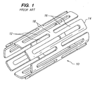
- FIG. 1 shows a typical prior art "expanding cage” stent design.
- the stent 10 includes a series of axial slots 12 formed in a cylindrical tube 14. Each axial row of slots 12 is displaced axially from the adjacent row by approximately half the slot length providing a staggered slot arrangement.
- the material between the slots 12 forms a network of axial struts 16 joined by short circumferential links 18.
- the cross section of each strut 16 remains constant or varies gradually along the entire length of the strut and thus the rectangular moment of inertia and the elastic and plastic section moduli of the cross section also remain constant or vary gradually along the length of the strut.
- Such a strut 16 is commonly referred to as a prismatic beam.
- Struts 16 in this type of design are typically 0.005 to 0.006 inches (0.127 - 0.1524 mm) wide in the circumferential direction. Strut thicknesses in the radial direction are typically about 0.0025 inches (0.0635 mm) or less to keep expansion forces within acceptable levels. However, most stent materials must be approximately 0.005 inches (0.127 mm) thick for good visibility on conventional fluoroscopic equipment. This high ratio of strut width to thickness, combined with the relatively high strut length and the initial curvature of the stent tubing combine to cause the instability and bucking often seen in this type of stent design. When expanded, the stent structure of FIG. 1 assumes the roughly diamond pattern commonly seen in expanded sheet metal.
- Another stent uses struts with relatively weak portions of locally-reduced cross sections that on expansion of the stent act to concentrate deformation at these areas.
- the locally-reduced cross section portions described in this document are formed by pairs of circular holes.
- the shape of the locally reduced cross section portions undesirably concentrates the plastic strain at the narrowest portion. This concentration of plastic strain without any provision for controlling the level of plastic strain makes the stent highly vulnerable to failure.
- U.S. Pat. No. 6,241,762 entitled “EXPANDABLE MEDICAL DEVICE WITH DUCTILE HINGES” filed October 10, 1998 and assigned to Conor Medsystems Inc., discloses a stent design that provides a stent with large, non-deforming strut and link elements, which can contain holes without compromising the mechanical properties of the strut or link elements, or the device as a whole. Further, these holes may serve as large, protected reservoirs for delivering various beneficial agents to the device implantation site.
- tissue-supporting device that could be expanded to a range of final diameters independent of the means of expansion or the force levels applied.
- the present invention makes novel use of hinges to provide both the spring force and two degrees-of-freedom motions required for a true self-locking expandable medical device design.
- the present invention provides a novel expandable medical device that is capable of self-expansion or expansion through the use of a balloon catheter or similar device.
- the expandable medical device according to the present invention may be utilized to deliver a beneficial agent to the area adjacent to the expanded medical device.
- an expandable medical device including a plurality of elongated beams.
- the plurality of elongated beams are joined together to form a substantially cylindrical device.
- the cylindrical device is expandable from a cylinder having a first diameter to a cylinder having a second diameter, the plurality of the elongated beams having a beam width in a circumferential direction.
- a plurality of hinges connected to the elongated beams have a hinge width, wherein the hinge width is smaller than the beam width.
- a pawl is disposed adjacent to and substantially parallel to the hinge prior to expansion of the medical device and a plurality of teeth are adapted to receive the pawl.
- an expandable medical device including a cylindrical tube and a plurality of axial slots formed in the cylindrical tube in an arrangement to define a network of elongated struts, wherein each of the elongated struts are radially displaced from adjacent struts, and each elongated strut further includes at least one tooth disposed thereupon.
- a pawl formed between the elongated strut has a distal end adapted to be received by the tooth.
- a plurality of hinges formed between the elongated struts allow the cylindrical tube to be expanded from a first diameter to a second diameter by bending of the hinges and engaging the distal end of the pawl with the tooth.
- an expandable medical device including, a cylindrical expandable body of Nitinol and a locking feature for locking the expanded body in an expanded position, wherein the locking mechanism prevents recoil of the expanded body of greater than 5 percent.
- a method of processing an expandable medical device including the steps of fabricating a cylindrical expandable medical device from martensitic Nitinol where the expandable medical device is fabricated with a first unexpanded diameter. Expanding the cylindrical expandable medical device to an expanded second diameter, wherein deformation during expansion is confined to a hinge and the deformation is below the elastic limit of the material. Processing the expandable medical device, and restoring the expandable medical device to the unexpanded first diameter by applying heat to the expandable medical device.
- an expandable medical device the expandable medical device includes a plurality of elongated beams and a plurality of hinges.
- the plurality of elongated beams joined together to form a substantially cylindrical device that is expandable to form a cylinder having a first diameter to a cylinder having a second diameter.
- the plurality of the elongated beams have a beam width in a circumferential direction, the beam width of the elongated beams being less than the width of the hinges.
- the expandable medical device further including an internal self locking mechanism.
- a method of constructing an expandable medical device including the steps of fabricating an expandable medical device from a cylindrical member, the expandable medical device is formed having a first unexpanded diameter, retracting the expandable medical device to an unexpanded second diameter where deformation during retraction is confined to a hinge portion of the expandable medical device, and retaining the expandable medical device in the unexpanded diameter.
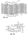
- the expandable medical device 200 includes a series of axial slots 210 formed in a cylindrical tube (not shown). Each axial slot 210 is displaced radially from the slots in the adjacent rows of slots by approximately 0.010 inches.
- the plurality of axial slots 210 define a plurality of elongated beams 220.
- the plurality of elongated beams 220 are interconnected by a hinge 250 disposed at one end and a locking area disposed at the other end.
- a U-shaped link 270 interconnects adjacent rows of beams 220.
- the elongated beam 220 further includes a pawl 230 having a distal end 235 disposed at one end of the elongated beam 220 and a plurality of teeth 240 disposed at the other end opposite the pawl 230.
- the elongated beam 220 further includes a hinge 250 adjacent the pawl 230.
- the hinge 250 further contains a first end 252 and a second end 254 defining a section 265, wherein the section 265 between the first end 252 and the second end 254 is designed where it will act as a stress/strain concentration area.
- the hinge 250 contains a first portion extending along about 1/3 of the length of the hinge 250 and a second section gradually tapering, extending about 2/3 of the length of the hinge 250.
- the length and width of the hinge can be adjusted to confine the maximum strain in the hinge 250, to some desired value at the maximum required bend radius of the hinge 250.
- the expandable medical device could be manufactured of materials such as titanium, stainless steel, polymers, or preferably a Nitinol alloy, wherein the Nitinol alloy may be either martensitic or austenitic super-elastic.
- the width of any feature is defined as its dimension in the circumferential direction of the cylinder.
- the length of any feature is defined as its dimension in the axial direction of the cylinder.
- the thickness of any feature is defined as the wall thickness of the cylinder.
- the distal end 235 of the pawl 230 is adjacent to the teeth 240 of the adjacent elongated member 220.
- FIG. 3A through 3C there is shown a plan view of a section of the expandable medical device 200 as the device is deployed.
- the expandable device 200 may be expanded radially by placing an appropriate device, such as a balloon catheter within the inner diameter of the expandable device 200 and expanding the balloon catheter until the expandable device has been expanded to a desired diameter.
- the expandable medical device 200 may be constructed having a plurality of apertures for receiving a beneficial agent, which may be released after insertion within a patient.
- a beneficial agent for delivering a beneficial agent, See co-pending U.S. Patent Application No. 09/649,217 entitled "Expandable Medical Device With Ductile Hinges", filed August 28, 2000.
- the expandable device 200 may be constructed of materials such as polymers, biodegradable materials, or combinations of polymers, biodegradable materials and Nitinol.
- the locking mechanism of the present invention provides the ability to decrease the recoil and increase the radial strength of expandable devices constructed of these materials, thereby allowing an expandable device to be constructed of these materials.
- the polymer and/or the biodegradable materials may be further adapted to receive a beneficial agent that may then be eluted after the expandable device is deployed within a patient.
- the beneficial agent may be contained within the polymer or biodegradable material, in which the characteristics of the polymer or biodegradable material control the release rate of the beneficial agent after the expandable device is deployed within a patient.
- the expandable device 200 includes a plurality of elongated members 220, spaced apart by radial slots 210.
- the elongated members have a pawl 230 disposed on one end thereof and a plurality of teeth 240 disposed on the other, and a hinge 250 adjacent to the pawl 230.
- the plurality of elongated members 220 are joined together by the hinge 250 and the locking configuration.
- the pawl 230 disposed at one end of an elongated member 220 is substantially parallel to hinge 250.
- the distal end 235 of the pawl 230 is designed having a 'chisel' shape adapted for being received by at least one of the plurality of teeth 240 on the adjacent substantially parallel elongated member 220.
- FIG. 3B there is shown the partial section of the expandable device 200 having been expanded to a second partially expanded diameter.
- a general rotational motion is achieved by pawl 230 as the diameter of the expandable device 200 is increased and hinge 250 bends.
- the locus of points drawn out by distal tip 235 of the pawl 230 as it rotates describes a non-circular arc.
- the hinge 250 bends initially about a pre-determined point within the region 265 as shown in Figure 3B .
- the pre-determined bending point is determined by narrowing the width of the hinge 250 within the section 265 as defined by the first end 252 and the second end 254 of the hinge 250.
- the expandable device of Figure 3B were fabricated of an martensitic Nitinol (shape memory) alloy, it could at this point be fully restored to the configuration of Figure 3A by heating the device above its transformation temperature. This is possible because the pawl has not yet engaged the first tooth in the adjacent strut, and the material is never stressed beyond its elastic limit. This feature is useful for intermediate fabrication steps, for example electropolishing, where the device can be expanded to an "open" configuration for more effective polishing and then thermally restored to a smaller diameter for mounting on a delivery system.
- martensitic Nitinol shape memory
- FIG. 3C there is shown the section of the expandable medical device 200 in an expanded state during engagement of the locking mechanism.
- a significant curvature develops in the hinge 250, specifically in the section 265.
- the pawl 230 and the distal end 235 of the pawl 230 become capable of both continued angular deflection, as indicated by arrow 300, and also a linear motion along the axis of the pawl 230, as indicated by arrow 320.
- the angular motion 300 and the linear motion 320 are both possible in this region because the axis of the pawl 230 is no longer directly aligned with the now-curved, centroidal axis of the hinge 250.
- the motion of the pawl 230 along its own axis requires only additional bending of the hinge 250 near second end 254 of the hinge 250.
- This ability of the hinge 250 to provide both the rotational motion 300 and the axial motion 320 allows the distal tip 235 of the pawl 230 to follow the contour of the teeth 240 without local plastic yielding of either feature.
- the elastic energy stored in the hinge 250 provides a means for creating a spring return force (not shown) that can be resolved at the distal tip 235 of the pawl into components parallel and perpendicular to the axis of the pawl.
- the teeth 240 may comprise many different geometrical shapes, which are adapted to receive the distal end 235 of the pawl 230.
- the teeth 240 may be comprised of depressions adapted to receive the distal end 235 of the pawl 230.
- the teeth 240 as shown and described are not to be considered limiting and are exemplary only; it is contemplated that the teeth 240 as well as the distal end 235 of the pawl 230 may comprise many different shapes as shall be apparent to one skilled in the art.
- the expandable medical device 200 when the expandable medical device 200, as described above, is fabricated from a Nitinol alloy, an exceptionally large sub-plastic strain range is available, and very large deformations are possible without exceeding the material's elastic limit. If the locking teeth of the expandable device 200 were absent, the device could be restored to its original shape by heating, since it is never plastically deformed during the expansion sequence of Figure 3 .
- the hinge 250 may be contoured as described above in order to control the bending pattern of the hinge 250 and thus the motion of the pawl during the bend sequence. For example, when the width of the hinge is narrowest near the pawl proximal end 232 of the pawl 230, the hinge tends to bend in this area first. As a result, the instant center of rotation of the pawl is initially closer to the proximal end 232 of the pawl 230, and the arc traced by the distal tip 235 of the pawl 230 quickly passes through the region 238 as indicated in Figures 3A-3C .
- distal tip 235 would again be circular, but in this case, the initial motion of the tip 235 would be parallel to the axis of pawl 230, the tip of the pawl would move away from contact with adjacent strut 220 from the outset, and no locking would be possible with teeth 240 of the adjacent strut 220.
- the relative motion of pawl 230 with respect to adjacent strut 220 containing teeth 240 may be optimized.
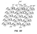
- FIG. 3D there is shown an exemplary alternative embodiment of the expandable device according to the present invention.
- FIG 3D there is shown a planar view of a representative portion of an unexpanded expandable medical device 200' in accordance with an alternative embodiment of the present invention.
- the expandable medical device 200' includes a series of spaced apart areas 211' formed within a cylindrical tube (not shown).
- the cylindrical tube being constructed of superelastic Nitinol alloy, wherein the cylindrical tube defines a first diameter of the expandable medical device 200'.
- the expandable medical device 200' can be formed in a semi-expanded state as shown in Figure 3D .
- Each spaced apart area 211' defines a plurality of elongated beams 220'.
- the plurality of elongated beams are interconnected by a hinge 250' disposed at one end and a locking area disposed at the other end.
- a U-shaped link 270' interconnects adjacent rows of beams 220'.
- the elongated beam 220' further includes a pawl 230' having a distal end 235' disposed at one end of the elongated beam 220' and a plurality of teeth 240' disposed at the other end opposite the pawl 230'.
- the hinge 250' further includes a first end 252' and a second end 254' defining a section 265', wherein the section 265' between the first end 252' and the second end 254' is designed where it will act as a stress/strain concentration area.
- the hinge 250' contains a first portion extending along about 1/3 of the length of the hinge 250' and a second section gradually tapering, extending about 2/3 of the length of the hinge 250'. It is contemplated that other ratios may be utilized as well as other geometries in order to confine the maximum stress/strain to the hinge section 265'.
- the length and width of the hinge can be adjusted to confine the maximum strain in the hinge 250' to some desired value at the maximum required bend radius of the hinge 250'.
- expandable medical device 200' is constructed in a semi-expanded state wherein the distal end 235' of the pawl 230' has not been engaged with the teeth 240'.
- the expandable medical device 200' By constructing the expandable medical device 200' in this manner enables the expandable medical device 200' to be reduced to a diameter less than the initial fabrication diameter of the cylindrical tube.
- a delivery device such as any of the delivery catheters available from many different manufacturers.
- the expandable medical device 200' may be retained in a compressed state through the use a removable sleeve or similar device such as those known to one skilled in the art.
- the expandable medical device 200' In use, the expandable medical device 200' would be placed within a patient's artery in a desired location, the sleeve or retaining device would be removed and/or activated wherein the expandable medical device 200' would then expand to the first diameter of the cylindrical tube which is the original fabrication diameter of the expandable medical device 200'.
- the expandable medical device 200' will automatically expand to this first diameter without the need to utilize any expanding means such as an inflatable balloon disposed within the inner diameter of the expandable medical device.
- the expandable medical device 200' can then be further expanded to engage the pawl and locking teeth, thereby locking the expandable medical device in an expanded position at a third diameter.
- the expandable device 200 is constructed of Nitinol alloy.
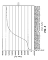
- Figure 5 there is shown a stress/strain diagram of a martensitic Nitinol alloy that may be utilized in the construction of the expandable device 200.
- the alloy 500 has a very low Young's Modulus, a low, nearly horizontal "de-twinning" stress plateau, and a 0.2% offset yield stress (elastic limit) of approximately 108 ksi. These characteristics provide an exceptionally large strain range before plastic deformation commences.
- This exceptionally large strain range when incorporated in the present invention, provides the benefit of a device that may be expanded from an initial diameter to a range of pre-determined diameters, the range of pre-determined diameters depend only on the geometry of the locking elements and not on the forces applied by an expansion means.
- the expandable device 200 of the present invention remains below its elastic limit before, during, and after the deployment of the device within an appropriate location.
- the locking mechanism 280 which includes the pawl 230, and the teeth 240, provides the ability to decrease the 'recoil' of the expandable device 200.
- stents that have been manufactured of Nitinol exhibit recoil percentages greater than many other suitable materials, thus Nitinol has not been commonly utilized for the construction of expandable stents.
- the locking mechanism 280 of the present invention reduces the amount of recoil associated with expandable Nitinol devices.
- the expandable device of the present invention exhibits recoil between about 2% and about 8%, and preferably between about 3% and about 5%.
- an expandable device may be constructed of a polymer, a biodegradable material, or a combination of a polymer and Nitinol.
- a further feature of the expandable devices in accordance with the present invention is the reduced necessity to over-expand the device in service.
- Prior art stents, and in particular nitinol stents often required over-expansion during deployment to achieve an acceptable "minimum lumen diameter," or MLD, post procedure. This is undesirable for several reasons, including the risk of collateral damage to the lumen, including perforation, and increased risk of long-term restenosis of the artery.
- MLD minimum lumen diameter
- the present invention easily permits additional expansion, if required: due to the plurality of teeth 240 provided on one end of the elongated member 220, the distal end 235 of the pawl 230 may be advanced to engage another one of the teeth 240, thereby increasing the overall expanded diameter of the expandable device 200.
- the expandable device 200/200' may further include a means for retaining and delivering a beneficial agent.
- the beams 220 may include a plurality of apertures (not shown) disposed there through, in which a beneficial agent may be disposed. After the expandable device 200 has been placed within a vessel/artery, the beneficial agent is released from the apertures in a controlled fashion.
- the expandable device 200 may be constructed from many different types of materials, such as, polymers, biodegradable materials, biocompatible materials, super-elastic alloys or a composite of any of the materials.
- constructing the expandable medical device 200' of superelastic Nitinol alloy further increases the safety of the expandable medical device. That is, the locking mechanism of the expandable medical devices in accordance with the present invention provides increased resistance to circumferential compression forces. Examples of such circumferential forces are artery spasms and elasticity of the artery wall or recoil as described above. Additionally, constructing the expandable medical device of superelastic Nitinol alloy allows the device to recover from deformations caused by forces applied perpendicular to the longitudinal axis of the device, such as flat plate crushing forces.
- the expandable medical device 200' may be utilized in a peripheral location such as the carotid artery, where the medical device is more vulnerable to being crushed by an external force or blow to the patient's neck.
- a conventional stainless steel stent cannot be utilized in this location because once deformed the stent will not return to its expanded state, thus potentially blocking the artery of which it was intended to support.
- the expandable medical device 200' in accordance with the present invention will return to its expanded and locked state if it is crushed due to an applied force because of the material properties of superelastic nitinol and the geometry of the expandable medical device 200'.
- An expandable medical device comprising: a plurality of elongated beams, the plurality of elongated beams joined together to form a substantially cylindrical device which is expandable from a cylinder having a first diameter to a cylinder having a second diameter, the plurality of the elongated beams having a beam width in a circumferential direction; a plurality of hinges connecting the elongated beams having a hinge width, wherein the hinge width is smaller than the beam width; a pawl disposed adjacent to and substantially parallel to the hinge prior to expansion of the medical device; a plurality of teeth adapted to receive the pawl.
- the hinges experience deformation below their elastic limit. Deformation during expansion is confined to the hinge. During expansion, the pawl experiences at least two degrees of freedom of motion. A distal tip of the pawl engages at least one of the plurality of teeth thereby retaining a generally cylindrical expanded second diameter. Recoil of the medical device after expansion is less than about eight percent.
- the expandable medical device may be manufactured from one of the materials selected from the group consisting of: polymers, Nitinol, martensitic Nitinol, superelastic Nitinol. Recoil of the medical device after expansion may also be less than about five percent.
- the expandable medical device may also be manufactured of a biodegradable material.
- the expandable medical device may also be manufactured of a composite of polymer and Nitinol.
- the expandable medical device may also be manufactured from martensitic Nitinol.
- the expandable medical device may also be manufactured from a continuous cylindrical body.
- the expandable medical device may also be laser-cut.
- the elongated beams of the expandable medical device may further include a plurality of apertures disposed therethrough, and a beneficial agent is disposed within the apertures.
- the polymer may include a beneficial agent, which is released from the polymer after insertion of the expandable medical device.
- the biodegradable material may also include a beneficial agent, which is released from the biodegradable material after insertion of the expandable medical device.
- the elongated beams may includes a plurality of apertures disposed therethrough, and a beneficial agent disposed within the apertures.
- the expandable medical device may comprise: a cylindrical tube; a plurality of axial slots formed in the cylindrical tube in an arrangement to define a network of elongated struts, wherein each of the elongated struts are radially displaced from adjacent struts, and each elongated strut further includes at least one tooth disposed thereupon; a pawl formed between the elongated struts, having a distal end adapted to be received by the tooth; and a plurality of hinges formed between the elongated struts the hinges allowing the cylindrical tube to be expanded from a first diameter to a second diameter by bending of the hinges and engaging the distal end of the pawl with the tooth.
- the bending of the pawl is controlled by the geometry of the hinge.
- the distal tip of the pawl prior to expansion, the distal tip of the pawl exhibits one degree of freedom, and develops a second degree of freedom along the axis of the pawl as sufficient bend angle is attained in the hinge.
- the expandable medical device may comprise: a cylindrical expandable body of Nitinol; and a locking feature for locking the expanded body in an expanded position, wherein the locking mechanism prevents recoil of the expanded body of greater than 6 percent.
- the locking feature includes a pawl disposed on one end of an elongated member and a plurality of teeth disposed on another adjacent elongated member and the pawl engages a tooth on the other elongated member when the expandable device is in an expanded position.
- the expandable medical device is constructed from a cylindrical body. In this embodiment, the recoil is less than 4 percent. The hinge undergoes deformation below its elastic limit as the expandable device is expanded.
- a method of processing an expandable medical device comprising: fabricating a cylindrical expandable medical device from martensitic Nitinol, wherein the expandable device has a first unexpanded diameter; expanding the cylindrical expandable medical device to an expanded second diameter, wherein deformation during expansion is confined to a hinge and the deformation is below the elastic limit of the material; processing the expandable medical device; and restoring the expandable medical device to the unexpanded first diameter by applying heat to the expandable medical device.
- the fabricating comprises cutting the expandable medical device from a continuous cylinder with a laser.
- the processing comprises electropolishing.
- the processing comprises coating.
- the processing comprises polishing.
- the expandable medical device comprises: a plurality of elongated beams, the plurality of elongated beams joined together to form a substantially cylindrical device which is expandable to form a cylinder having a first diameter to a cylinder having a second diameter, the plurality of the elongated beams having a beam width in a circumferential direction; a plurality of hinges having a hinge width, wherein the hinge width is smaller than the beam width; and an internal self locking mechanism.
- the internal self-locking mechanism may comprise a pawl and a plurality of teeth adapted to receive the pawl.
- the step of retaining the expandable medical device includes disposing a retaining means about the unexpanded second diameter of the expandable medical device.
- Further steps may include: disposing the retracted expandable medical device onto a delivery device; placing the delivery device within an artery of a patient; and removing said retaining means wherein the expandable medical device returns to said first unexpanded diameter.
- a further step is included of expanding the expandable medical device to an expanded diameter larger than the first unexpanded diameter wherein a locking means is engaged to retain the expandable medical device in said first expanded diameter.
Abstract
Description
- This invention relates to expandable medical devices, more particularly to a medical device which is expandable.
- In the past, permanent or biodegradable devices have been developed for implantation within a body passageway to maintain patency of the passageway. These devices are typically introduced percutaneously, and transported transluminally until positioned at a desired location. These devices are then expanded either mechanically, such as by the expansion of a mandrel or balloon positioned inside the device, or expand themselves by releasing stored energy upon actuation within the body. Once expanded within the lumen, these devices, called stents, become encapsulated within the body tissue and remain a permanent implant.
- Known stent designs include monofilament wire coil stents (
U.S. Pat. No. 4,969,458 ); welded metal cages (U.S. Pat. Nos. 4,733,665 and4,776,337 ); and, most prominently, thin-walled metal cylinders with axial slots formed around the circumference (U.S. Pat. Nos. 4,733,665 ,4,739,762 , and4,776,337 ). Known construction materials for use in stents include polymers, organic fabrics and biocompatible metals, such as, stainless steel, gold, silver, tantalum, titanium, and shape memory alloys such as Nitinol. -
U.S. Pat. Nos. 4,733,665 ,4,739,762 , and4,776,337 disclose expandable and deformable intraluminal vascular grafts in the form of thin-walled tubular members with axial slots allowing the members to be expanded radially outwardly into contact with a body passageway. After insertion, the tubular members are mechanically expanded beyond their elastic limit and thus permanently fixed within the body. - Many of the known stents display a large elastic recovery, known in the field as "recoil," after expansion inside a lumen. Large recoil necessitates over-expansion of the stent during implantation to achieve the desired final diameter. Over-expansion is potentially destructive to the lumen tissue and is known to cause higher rates of restenosis. Known stents of the type described above experience recoil of up to about 9 to 21% from maximum expansion.
- Large recoil also makes it very difficult to securely crimp most known stents onto delivery catheter balloons. As a result, slippage of stents on balloons during intralumenal transportation, final positioning, and implantation has been an ongoing problem. Many ancillary stent securing devices and techniques have been advanced to attempt to compensate for this basic design problem. Some of the stent securing devices include collars and sleeves used to secure the stent onto the balloon.
- Some materials have intrinsic properties that are beneficial in some aspects of stent design, and undesirable in other aspects.
U.S. Pat. No. 5,545,210 , for example, discloses a thin-walled tubular stent geometrically similar to those discussed above, but constructed of a nickel-titanium shape memory alloy ("Nitinol"). Martensitic Nitinol has a very low Young's Modulus, and a low, nearly horizontal "de-twinning" stress plateau that provide an exceptionally large strain range before plastic deformation commences. When incorporated into conventional stent designs, these properties produce stents that have unusually good flexibility, deliverability, conformability and radiopacity, but also unacceptably high recoil and poor radial strength. For example, recoil of a typical design Nitinol stent ranges from 10% to 25%, typically about 12% to 16%. - One approach to remedying material-based recoil and radial strength problems is to employ locking or detent features in the stent design. A number of such locking stent designs have been proposed for conventional materials like stainless steel, but none has proven workable in practice.
- Many of the designs are simply impossible to manufacture on a small scale. More fundamentally, most of the designs fail to provide the basic mechanical requirements of a ratchet or detent mechanism: 1) two degree-of-freedom differential motion between the engaging elements, and 2) a restoring or spring force between the elements. It is relatively easy to provide these two elements in larger mechanisms comprised of discrete components, but much more difficult to provide this functionality while cutting all features into a very small, continuous, cylindrical surface.
-
FIG. 1 shows a typical prior art "expanding cage" stent design. Thestent 10 includes a series ofaxial slots 12 formed in acylindrical tube 14. Each axial row ofslots 12 is displaced axially from the adjacent row by approximately half the slot length providing a staggered slot arrangement. The material between theslots 12 forms a network ofaxial struts 16 joined by shortcircumferential links 18. The cross section of eachstrut 16 remains constant or varies gradually along the entire length of the strut and thus the rectangular moment of inertia and the elastic and plastic section moduli of the cross section also remain constant or vary gradually along the length of the strut. Such astrut 16 is commonly referred to as a prismatic beam.Struts 16 in this type of design are typically 0.005 to 0.006 inches (0.127 - 0.1524 mm) wide in the circumferential direction. Strut thicknesses in the radial direction are typically about 0.0025 inches (0.0635 mm) or less to keep expansion forces within acceptable levels. However, most stent materials must be approximately 0.005 inches (0.127 mm) thick for good visibility on conventional fluoroscopic equipment. This high ratio of strut width to thickness, combined with the relatively high strut length and the initial curvature of the stent tubing combine to cause the instability and bucking often seen in this type of stent design. When expanded, the stent structure ofFIG. 1 assumes the roughly diamond pattern commonly seen in expanded sheet metal. - Another stent, described in
PCT publication number WO 96/29028 -
U.S. Pat. No. 6,241,762 , entitled "EXPANDABLE MEDICAL DEVICE WITH DUCTILE HINGES" filed October 10, 1998 and assigned to Conor Medsystems Inc., discloses a stent design that provides a stent with large, non-deforming strut and link elements, which can contain holes without compromising the mechanical properties of the strut or link elements, or the device as a whole. Further, these holes may serve as large, protected reservoirs for delivering various beneficial agents to the device implantation site. - In view of the drawbacks of prior art stents, it would be advantageous to have an expandable medical device with low radial recoil and high radial force (circumferential crush strength) independent of the intrinsic properties of the material of fabrication.
- It would further be advantageous to have a tissue-supporting device that could be expanded to a range of final diameters independent of the means of expansion or the force levels applied.
- It would also be desirable to control the maximum material strain to a desired level wherein when the expandable medical device is deployed the material remains below its elastic limit, and may be expanded to a greater diameter if necessary without plastically deforming the material.
- The present invention makes novel use of hinges to provide both the spring force and two degrees-of-freedom motions required for a true self-locking expandable medical device design. In addition to that above the present invention provides a novel expandable medical device that is capable of self-expansion or expansion through the use of a balloon catheter or similar device. Further still, the expandable medical device according to the present invention may be utilized to deliver a beneficial agent to the area adjacent to the expanded medical device.
- In accordance with one aspect of the present invention there is provided an expandable medical device including a plurality of elongated beams. The plurality of elongated beams are joined together to form a substantially cylindrical device. The cylindrical device is expandable from a cylinder having a first diameter to a cylinder having a second diameter, the plurality of the elongated beams having a beam width in a circumferential direction. A plurality of hinges connected to the elongated beams have a hinge width, wherein the hinge width is smaller than the beam width. A pawl is disposed adjacent to and substantially parallel to the hinge prior to expansion of the medical device and a plurality of teeth are adapted to receive the pawl.
- In accordance with another aspect of the present invention there is provided an expandable medical device including a cylindrical tube and a plurality of axial slots formed in the cylindrical tube in an arrangement to define a network of elongated struts, wherein each of the elongated struts are radially displaced from adjacent struts, and each elongated strut further includes at least one tooth disposed thereupon. A pawl formed between the elongated strut has a distal end adapted to be received by the tooth. A plurality of hinges formed between the elongated struts allow the cylindrical tube to be expanded from a first diameter to a second diameter by bending of the hinges and engaging the distal end of the pawl with the tooth.
- In accordance with another aspect of the present invention there is provided an expandable medical device including, a cylindrical expandable body of Nitinol and a locking feature for locking the expanded body in an expanded position, wherein the locking mechanism prevents recoil of the expanded body of greater than 5 percent.
- In accordance with another aspect of the present invention there is provided a method of processing an expandable medical device, the method including the steps of fabricating a cylindrical expandable medical device from martensitic Nitinol where the expandable medical device is fabricated with a first unexpanded diameter. Expanding the cylindrical expandable medical device to an expanded second diameter, wherein deformation during expansion is confined to a hinge and the deformation is below the elastic limit of the material. Processing the expandable medical device, and restoring the expandable medical device to the unexpanded first diameter by applying heat to the expandable medical device.
- In accordance with another aspect of the present invention there is provided an expandable medical device, the expandable medical device includes a plurality of elongated beams and a plurality of hinges. The plurality of elongated beams joined together to form a substantially cylindrical device that is expandable to form a cylinder having a first diameter to a cylinder having a second diameter. The plurality of the elongated beams have a beam width in a circumferential direction, the beam width of the elongated beams being less than the width of the hinges. The expandable medical device further including an internal self locking mechanism.
- In accordance with yet another aspect of the present invention there is provided a method of constructing an expandable medical device. The method including the steps of fabricating an expandable medical device from a cylindrical member, the expandable medical device is formed having a first unexpanded diameter, retracting the expandable medical device to an unexpanded second diameter where deformation during retraction is confined to a hinge portion of the expandable medical device, and retaining the expandable medical device in the unexpanded diameter.
- The invention will now be described in greater detail with reference to the preferred embodiments illustrated in the accompanying drawings, in which like elements utilize like reference numerals, and wherein;
-
Figure 1 is an isometric view of a prior art tissue-supporting device; -
Figure 2A is a planar view of a representative portion of an unexpanded tissue-supporting device in accordance with one embodiment of the invention; -
Figure 2B is a sectional planar view of a single expanding member in accordance with the present invention; -
Figure 3A is a detail view of the expandable medical device ofFigure 2 undergoing sequential expansion; -
Figure 3B is a detail view of the expandable medical device ofFigure 2 undergoing sequential expansion; -
Figure 3C is a detail view of the expandable medical device ofFigure 2 undergoing sequential expansion; -
Figure 3D is a detail view of an alternative embodiment of the expandable medical device in accordance with the present invention; -
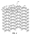
Figure 4 is a planar view of the expandable device of the present invention in an expanded and locked state; and -
Figure 5 is a stress/strain curve of a martensitic Nitinol alloy illustrating the extended sub-plastic strain range and the horizontal "de-twinning plateau" of the material. - Referring now to
Figures 2A and 2B , there is shown a planar view of a representative portion of an unexpanded tissue-supportingmedical device 200. The expandablemedical device 200 includes a series ofaxial slots 210 formed in a cylindrical tube (not shown). Eachaxial slot 210 is displaced radially from the slots in the adjacent rows of slots by approximately 0.010 inches. The plurality ofaxial slots 210 define a plurality ofelongated beams 220. The plurality ofelongated beams 220 are interconnected by ahinge 250 disposed at one end and a locking area disposed at the other end. AU-shaped link 270 interconnects adjacent rows ofbeams 220. - The
elongated beam 220 further includes apawl 230 having adistal end 235 disposed at one end of theelongated beam 220 and a plurality ofteeth 240 disposed at the other end opposite thepawl 230. Theelongated beam 220 further includes ahinge 250 adjacent thepawl 230. Thehinge 250 further contains afirst end 252 and asecond end 254 defining asection 265, wherein thesection 265 between thefirst end 252 and thesecond end 254 is designed where it will act as a stress/strain concentration area. Specifically, thehinge 250 contains a first portion extending along about 1/3 of the length of thehinge 250 and a second section gradually tapering, extending about 2/3 of the length of thehinge 250. It is contemplated that other ratios may be utilized as well as other geometries in order to confine the maximum stress/strain to thehinge section 265. Furthermore, the length and width of the hinge can be adjusted to confine the maximum strain in thehinge 250, to some desired value at the maximum required bend radius of thehinge 250. - For example, if the maximum desired bend angle of the
hinge 250 was set at ninety (90) degrees, and the minimum hinge width was fixed at about .002 inches, a hinge length could be determined which would guarantee that the maximum strain in thehinge 250 was well below the elastic limit of some specified material. For example, the expandable medical device could be manufactured of materials such as titanium, stainless steel, polymers, or preferably a Nitinol alloy, wherein the Nitinol alloy may be either martensitic or austenitic super-elastic. - With reference to the drawings and the discussion, the width of any feature is defined as its dimension in the circumferential direction of the cylinder. The length of any feature is defined as its dimension in the axial direction of the cylinder. The thickness of any feature is defined as the wall thickness of the cylinder.
- When manufactured as a continuous array as shown in
Figure 2 , thedistal end 235 of thepawl 230 is adjacent to theteeth 240 of the adjacentelongated member 220. - Referring now to
Figures 3A through 3C there is shown a plan view of a section of the expandablemedical device 200 as the device is deployed. Theexpandable device 200 may be expanded radially by placing an appropriate device, such as a balloon catheter within the inner diameter of theexpandable device 200 and expanding the balloon catheter until the expandable device has been expanded to a desired diameter. - Additionally the expandable
medical device 200 may be constructed having a plurality of apertures for receiving a beneficial agent, which may be released after insertion within a patient. For a more detailed description of the apparatus and methods for delivering a beneficial agent, See co-pendingU.S. Patent Application No. 09/649,217 - Furthermore, the
expandable device 200 may be constructed of materials such as polymers, biodegradable materials, or combinations of polymers, biodegradable materials and Nitinol. The locking mechanism of the present invention provides the ability to decrease the recoil and increase the radial strength of expandable devices constructed of these materials, thereby allowing an expandable device to be constructed of these materials. - The polymer and/or the biodegradable materials may be further adapted to receive a beneficial agent that may then be eluted after the expandable device is deployed within a patient. For example, the beneficial agent may be contained within the polymer or biodegradable material, in which the characteristics of the polymer or biodegradable material control the release rate of the beneficial agent after the expandable device is deployed within a patient.
- As shown in
Figure 3A , a partial section of theexpandable device 200 is shown. As described in detail above, theexpandable device 200 includes a plurality ofelongated members 220, spaced apart byradial slots 210. The elongated members have apawl 230 disposed on one end thereof and a plurality ofteeth 240 disposed on the other, and ahinge 250 adjacent to thepawl 230. The plurality ofelongated members 220 are joined together by thehinge 250 and the locking configuration. In an unexpanded state, as shown inFigure 3A , thepawl 230 disposed at one end of anelongated member 220 is substantially parallel to hinge 250. Further still thedistal end 235 of thepawl 230 is designed having a 'chisel' shape adapted for being received by at least one of the plurality ofteeth 240 on the adjacent substantially parallelelongated member 220. - Referring now to
Figure 3B , there is shown the partial section of theexpandable device 200 having been expanded to a second partially expanded diameter. As indicated by arrow 300 a general rotational motion is achieved bypawl 230 as the diameter of theexpandable device 200 is increased and hinge 250 bends. As shown, the locus of points drawn out bydistal tip 235 of thepawl 230 as it rotates describes a non-circular arc. Thehinge 250 bends initially about a pre-determined point within theregion 265 as shown inFigure 3B . The pre-determined bending point is determined by narrowing the width of thehinge 250 within thesection 265 as defined by thefirst end 252 and thesecond end 254 of thehinge 250. As shownFigure 3B , as the pawl rotates during expansion of the device from an unexpanded state as shown inFigure 3A to a partially expanded state as shown inFigure 3B thepawl 230 is no longer substantially parallel to thehinge 250 due to the bending of thehinge 250. - If the expandable device of
Figure 3B were fabricated of an martensitic Nitinol (shape memory) alloy, it could at this point be fully restored to the configuration ofFigure 3A by heating the device above its transformation temperature. This is possible because the pawl has not yet engaged the first tooth in the adjacent strut, and the material is never stressed beyond its elastic limit. This feature is useful for intermediate fabrication steps, for example electropolishing, where the device can be expanded to an "open" configuration for more effective polishing and then thermally restored to a smaller diameter for mounting on a delivery system. - Referring now to
Figure 3C , there is shown the section of the expandablemedical device 200 in an expanded state during engagement of the locking mechanism. As shown, a significant curvature develops in thehinge 250, specifically in thesection 265. As this curvature occurs, thepawl 230 and thedistal end 235 of thepawl 230 become capable of both continued angular deflection, as indicated byarrow 300, and also a linear motion along the axis of thepawl 230, as indicated byarrow 320. Theangular motion 300 and thelinear motion 320 are both possible in this region because the axis of thepawl 230 is no longer directly aligned with the now-curved, centroidal axis of thehinge 250. Rather, the motion of thepawl 230 along its own axis requires only additional bending of thehinge 250 nearsecond end 254 of thehinge 250. This ability of thehinge 250 to provide both therotational motion 300 and theaxial motion 320 allows thedistal tip 235 of thepawl 230 to follow the contour of theteeth 240 without local plastic yielding of either feature. Additionally, the elastic energy stored in thehinge 250 provides a means for creating a spring return force (not shown) that can be resolved at thedistal tip 235 of the pawl into components parallel and perpendicular to the axis of the pawl. When the expansion device has positioned thedistal tip 235 of thepawl 230 beyond one of the lockingteeth 240, and the expansion device is then withdrawn, these spring return forces force thedistal tip 235 to contact the lockingtooth 240, thereby locking theexpandable device 200 into an expanded state as shown inFigure 4 . The mating faces of thedistal tip 235 and the lockingtooth 240 are contoured according to well-known techniques to insure that forces that are externally applied to the tissue-supportingdevice 200 act to further lock the features in position. Furthermore, throughout the description reference is made to theteeth 240, it shall be understood that this reference should not be considered limiting. For example, theteeth 240 may comprise many different geometrical shapes, which are adapted to receive thedistal end 235 of thepawl 230. For example, theteeth 240 may be comprised of depressions adapted to receive thedistal end 235 of thepawl 230. Thus, theteeth 240 as shown and described are not to be considered limiting and are exemplary only; it is contemplated that theteeth 240 as well as thedistal end 235 of thepawl 230 may comprise many different shapes as shall be apparent to one skilled in the art. - For example, when the expandable
medical device 200, as described above, is fabricated from a Nitinol alloy, an exceptionally large sub-plastic strain range is available, and very large deformations are possible without exceeding the material's elastic limit. If the locking teeth of theexpandable device 200 were absent, the device could be restored to its original shape by heating, since it is never plastically deformed during the expansion sequence ofFigure 3 . - Additionally, the
hinge 250 may be contoured as described above in order to control the bending pattern of thehinge 250 and thus the motion of the pawl during the bend sequence. For example, when the width of the hinge is narrowest near the pawlproximal end 232 of thepawl 230, the hinge tends to bend in this area first. As a result, the instant center of rotation of the pawl is initially closer to theproximal end 232 of thepawl 230, and the arc traced by thedistal tip 235 of thepawl 230 quickly passes through theregion 238 as indicated inFigures 3A-3C . This may be visualized by imagining the limiting case of a simple pivot point located atend 252 ofhinge 250 the arc traced bydistal tip 235 would in this case be circular, and the initial motion of thetip 235 would be orthogonal to the axis of pawl 230 (i.e., downward, or directly toward the adjacent strut 220). The second limiting case would correspond to a pivot point at theother end 254 ofhinge 250. The arc traced bydistal tip 235 would again be circular, but in this case, the initial motion of thetip 235 would be parallel to the axis ofpawl 230, the tip of the pawl would move away from contact withadjacent strut 220 from the outset, and no locking would be possible withteeth 240 of theadjacent strut 220. By contouring the shape ofhinge 250 between these extremes, the relative motion ofpawl 230 with respect toadjacent strut 220 containingteeth 240 may be optimized. - Referring now to
Figure 3D there is shown an exemplary alternative embodiment of the expandable device according to the present invention. Referring toFigure 3D there is shown a planar view of a representative portion of an unexpanded expandable medical device 200' in accordance with an alternative embodiment of the present invention. The expandable medical device 200' includes a series of spaced apart areas 211' formed within a cylindrical tube (not shown). The cylindrical tube being constructed of superelastic Nitinol alloy, wherein the cylindrical tube defines a first diameter of the expandable medical device 200'. By utilizing a superelastic Nitinol alloy for the construction of the expandable medical device 200', the expandable medical device 200' can be formed in a semi-expanded state as shown inFigure 3D . Each spaced apart area 211' defines a plurality of elongated beams 220'. The plurality of elongated beams are interconnected by a hinge 250' disposed at one end and a locking area disposed at the other end. A U-shaped link 270' interconnects adjacent rows of beams 220'. As shown, the elongated beam 220' further includes a pawl 230' having a distal end 235' disposed at one end of the elongated beam 220' and a plurality of teeth 240' disposed at the other end opposite the pawl 230'. The hinge 250' further includes a first end 252' and a second end 254' defining a section 265', wherein the section 265' between the first end 252' and the second end 254' is designed where it will act as a stress/strain concentration area. Specifically, the hinge 250' contains a first portion extending along about 1/3 of the length of the hinge 250' and a second section gradually tapering, extending about 2/3 of the length of the hinge 250'. It is contemplated that other ratios may be utilized as well as other geometries in order to confine the maximum stress/strain to the hinge section 265'. Furthermore, the length and width of the hinge can be adjusted to confine the maximum strain in the hinge 250' to some desired value at the maximum required bend radius of the hinge 250'. - As shown in
Figure 3D , it can be seen that expandable medical device 200' is constructed in a semi-expanded state wherein the distal end 235' of the pawl 230' has not been engaged with the teeth 240'. By constructing the expandable medical device 200' in this manner enables the expandable medical device 200' to be reduced to a diameter less than the initial fabrication diameter of the cylindrical tube. By reducing the diameter of the expandable medical device 200' it can be loaded onto a delivery device such as any of the delivery catheters available from many different manufacturers. The expandable medical device 200' may be retained in a compressed state through the use a removable sleeve or similar device such as those known to one skilled in the art. - In use, the expandable medical device 200' would be placed within a patient's artery in a desired location, the sleeve or retaining device would be removed and/or activated wherein the expandable medical device 200' would then expand to the first diameter of the cylindrical tube which is the original fabrication diameter of the expandable medical device 200'. The expandable medical device 200' will automatically expand to this first diameter without the need to utilize any expanding means such as an inflatable balloon disposed within the inner diameter of the expandable medical device. The expandable medical device 200' can then be further expanded to engage the pawl and locking teeth, thereby locking the expandable medical device in an expanded position at a third diameter.
- Throughout this description reference has been made to materials that may be utilized in the construction of the
expandable device 200. In a preferred embodiment theexpandable device 200 is constructed of Nitinol alloy. Referring now toFigure 5 , there is shown a stress/strain diagram of a martensitic Nitinol alloy that may be utilized in the construction of theexpandable device 200. As shown inFigure 5 , the alloy 500 has a very low Young's Modulus, a low, nearly horizontal "de-twinning" stress plateau, and a 0.2% offset yield stress (elastic limit) of approximately 108 ksi. These characteristics provide an exceptionally large strain range before plastic deformation commences. - This exceptionally large strain range, when incorporated in the present invention, provides the benefit of a device that may be expanded from an initial diameter to a range of pre-determined diameters, the range of pre-determined diameters depend only on the geometry of the locking elements and not on the forces applied by an expansion means. By utilizing the elastic and "de-twinning" strain ranges of Nitinol, the
expandable device 200 of the present invention remains below its elastic limit before, during, and after the deployment of the device within an appropriate location. - Furthermore, the locking mechanism 280, which includes the
pawl 230, and theteeth 240, provides the ability to decrease the 'recoil' of theexpandable device 200. As described in detail above, stents that have been manufactured of Nitinol exhibit recoil percentages greater than many other suitable materials, thus Nitinol has not been commonly utilized for the construction of expandable stents. The locking mechanism 280 of the present invention reduces the amount of recoil associated with expandable Nitinol devices. For example, the expandable device of the present invention exhibits recoil between about 2% and about 8%, and preferably between about 3% and about 5%. Additionally, due to the locking mechanism 280 of the present invention, other materials may be utilized in the construction of expandable medical devices that could not have been utilized before due to large recoil percentages of the material. For example, an expandable device may be constructed of a polymer, a biodegradable material, or a combination of a polymer and Nitinol. - A further feature of the expandable devices in accordance with the present invention is the reduced necessity to over-expand the device in service. Prior art stents, and in particular nitinol stents often required over-expansion during deployment to achieve an acceptable "minimum lumen diameter," or MLD, post procedure. This is undesirable for several reasons, including the risk of collateral damage to the lumen, including perforation, and increased risk of long-term restenosis of the artery. Once the desired MLD has been achieved in the present invention, however, that diameter can be sustained without additional expansion due to the locking mechanism. At the same time, the present invention easily permits additional expansion, if required: due to the plurality of
teeth 240 provided on one end of theelongated member 220, thedistal end 235 of thepawl 230 may be advanced to engage another one of theteeth 240, thereby increasing the overall expanded diameter of theexpandable device 200. - In addition to the embodiments above, it is contemplated that the
expandable device 200/200' may further include a means for retaining and delivering a beneficial agent. For example, thebeams 220 may include a plurality of apertures (not shown) disposed there through, in which a beneficial agent may be disposed. After theexpandable device 200 has been placed within a vessel/artery, the beneficial agent is released from the apertures in a controlled fashion. Furthermore, it is contemplated that theexpandable device 200 may be constructed from many different types of materials, such as, polymers, biodegradable materials, biocompatible materials, super-elastic alloys or a composite of any of the materials. - Still further, constructing the expandable medical device 200' of superelastic Nitinol alloy further increases the safety of the expandable medical device. That is, the locking mechanism of the expandable medical devices in accordance with the present invention provides increased resistance to circumferential compression forces. Examples of such circumferential forces are artery spasms and elasticity of the artery wall or recoil as described above. Additionally, constructing the expandable medical device of superelastic Nitinol alloy allows the device to recover from deformations caused by forces applied perpendicular to the longitudinal axis of the device, such as flat plate crushing forces. For example, the expandable medical device 200' may be utilized in a peripheral location such as the carotid artery, where the medical device is more vulnerable to being crushed by an external force or blow to the patient's neck. A conventional stainless steel stent cannot be utilized in this location because once deformed the stent will not return to its expanded state, thus potentially blocking the artery of which it was intended to support. By contrast, the expandable medical device 200' in accordance with the present invention will return to its expanded and locked state if it is crushed due to an applied force because of the material properties of superelastic nitinol and the geometry of the expandable medical device 200'.
- While the invention has been described in detail with reference to the preferred embodiments thereof, it will be apparent to one skilled in the art that various changes and modifications can be made and equivalents employed, without departing from the present invention.
- An expandable medical device is disclosed, comprising: a plurality of elongated beams, the plurality of elongated beams joined together to form a substantially cylindrical device which is expandable from a cylinder having a first diameter to a cylinder having a second diameter, the plurality of the elongated beams having a beam width in a circumferential direction; a plurality of hinges connecting the elongated beams having a hinge width, wherein the hinge width is smaller than the beam width; a pawl disposed adjacent to and substantially parallel to the hinge prior to expansion of the medical device; a plurality of teeth adapted to receive the pawl.
- During expansion the hinges experience deformation below their elastic limit. Deformation during expansion is confined to the hinge. During expansion, the pawl experiences at least two degrees of freedom of motion. A distal tip of the pawl engages at least one of the plurality of teeth thereby retaining a generally cylindrical expanded second diameter. Recoil of the medical device after expansion is less than about eight percent.
- The expandable medical device may be manufactured from one of the materials selected from the group consisting of: polymers, Nitinol, martensitic Nitinol, superelastic Nitinol. Recoil of the medical device after expansion may also be less than about five percent. The expandable medical device may also be manufactured of a biodegradable material. The expandable medical device may also be manufactured of a composite of polymer and Nitinol. The expandable medical device may also be manufactured from martensitic Nitinol. The expandable medical device may also be manufactured from a continuous cylindrical body. The expandable medical device may also be laser-cut.
- The elongated beams of the expandable medical device may further include a plurality of apertures disposed therethrough, and a beneficial agent is disposed within the apertures. The polymer may include a beneficial agent, which is released from the polymer after insertion of the expandable medical device. The biodegradable material may also include a beneficial agent, which is released from the biodegradable material after insertion of the expandable medical device. In the expandable medical device the elongated beams may includes a plurality of apertures disposed therethrough, and a beneficial agent disposed within the apertures.
- The expandable medical device may comprise: a cylindrical tube; a plurality of axial slots formed in the cylindrical tube in an arrangement to define a network of elongated struts, wherein each of the elongated struts are radially displaced from adjacent struts, and each elongated strut further includes at least one tooth disposed thereupon; a pawl formed between the elongated struts, having a distal end adapted to be received by the tooth; and a plurality of hinges formed between the elongated struts the hinges allowing the cylindrical tube to be expanded from a first diameter to a second diameter by bending of the hinges and engaging the distal end of the pawl with the tooth. In the expandable medical device the bending of the pawl is controlled by the geometry of the hinge. In the expandable medical device, prior to expansion, the distal tip of the pawl exhibits one degree of freedom, and develops a second degree of freedom along the axis of the pawl as sufficient bend angle is attained in the hinge.
- In a further embodiment, the expandable medical device may comprise: a cylindrical expandable body of Nitinol; and a locking feature for locking the expanded body in an expanded position, wherein the locking mechanism prevents recoil of the expanded body of greater than 6 percent. The locking feature includes a pawl disposed on one end of an elongated member and a plurality of teeth disposed on another adjacent elongated member and the pawl engages a tooth on the other elongated member when the expandable device is in an expanded position. The expandable medical device is constructed from a cylindrical body. In this embodiment, the recoil is less than 4 percent. The hinge undergoes deformation below its elastic limit as the expandable device is expanded.
- A method of processing an expandable medical device is also disclosed, the method comprising: fabricating a cylindrical expandable medical device from martensitic Nitinol, wherein the expandable device has a first unexpanded diameter; expanding the cylindrical expandable medical device to an expanded second diameter, wherein deformation during expansion is confined to a hinge and the deformation is below the elastic limit of the material; processing the expandable medical device; and restoring the expandable medical device to the unexpanded first diameter by applying heat to the expandable medical device. The fabricating comprises cutting the expandable medical device from a continuous cylinder with a laser. The processing comprises electropolishing. The processing comprises coating. The processing comprises polishing.
- In a further embodiment, the expandable medical device comprises: a plurality of elongated beams, the plurality of elongated beams joined together to form a substantially cylindrical device which is expandable to form a cylinder having a first diameter to a cylinder having a second diameter, the plurality of the elongated beams having a beam width in a circumferential direction; a plurality of hinges having a hinge width, wherein the hinge width is smaller than the beam width; and an internal self locking mechanism. The internal self-locking mechanism may comprise a pawl and a plurality of teeth adapted to receive the pawl. The step of retaining the expandable medical device includes disposing a retaining means about the unexpanded second diameter of the expandable medical device. Further steps may include: disposing the retracted expandable medical device onto a delivery device; placing the delivery device within an artery of a patient; and removing said retaining means wherein the expandable medical device returns to said first unexpanded diameter. A further step is included of expanding the expandable medical device to an expanded diameter larger than the first unexpanded diameter wherein a locking means is engaged to retain the expandable medical device in said first expanded diameter.
Claims (11)
- A beneficial agent for use in a method of maintaining patency of a body passageway, comprising:fabricating an expandable medical device from a cylindrical member, wherein the expandable device is formed having a first unexpanded diameter, the expandable medical device having a plurality of elongated beams interconnected by hinge portions;disposing the beneficial agent in a plurality of apertures disposed through the beams of the expandable device;retracting the expandable medical device to an unexpanded second diameter, wherein deformation during retraction is confined to the hinge portions of the expandable medical device;retaining the expandable medical device in said unexpanded second diameter;disposing the retracted expandable medical device onto a delivery device;placing the delivery device within an artery or vessel of the patient; andreturning the expandable medical device to said first unexpanded diameter.
- The beneficial agent of claim 1, the method further comprising releasing the beneficial agent from the apertures in a controlled fashion.
- The beneficial agent of claim 1 or 2, wherein the fabricating includes the constructing of the expandable device from polymers and/or biodegradable materials.
- The beneficial agent of claim 3, wherein the polymers and/or biodegradable materials are further adapted to receive the beneficial agent so as to be eluted therefrom after deployment of the device within the patient.
- The beneficial agent of claim 4, wherein the polymers and/or biodegradable materials control the release rate of the beneficial agent contained therein.
- The beneficial agent of one of claims 1 to 5, wherein the fabricating includes forming a series of axial slots in a cylindrical tube, such that the plurality of the slots define the plurality of the elongated beams.
- The beneficial agent of one of claims 1 to 6, wherein adjacent rows of the elongated beams are interconnected by U shaped links.
- The beneficial agent of one of claims 1 to 7, wherein each of the hinge portions comprises a gradually tapering section.
- The beneficial agent of claim 8, wherein the tapering section extends about 2/3 of a length of the hinge.
- The beneficial agent of one of claims 1 to 9, the method including disposing a retaining means about the unexpanded second diameter of the expandable medical device, and after deployment, removing said retaining means.
- The beneficial agent of one of claims 1 to 10, wherein the method includes further expanding the device to an expanded position at a third diameter.
Applications Claiming Priority (4)
| Application Number | Priority Date | Filing Date | Title |
|---|---|---|---|
| US26680501P | 2001-02-05 | 2001-02-05 | |
| US10/057,414 US6964680B2 (en) | 2001-02-05 | 2002-01-25 | Expandable medical device with tapered hinge |
| EP05009096A EP1557140A3 (en) | 2001-02-05 | 2002-02-04 | Expandable medical device |
| EP02705808A EP1359867B1 (en) | 2001-02-05 | 2002-02-04 | Expandable medical device with locking mechanism |
Related Parent Applications (2)
| Application Number | Title | Priority Date | Filing Date |
|---|---|---|---|
| EP02705808.0 Division | 2002-02-04 | ||
| EP05009096.8 Division | 2005-04-26 |
Publications (1)
| Publication Number | Publication Date |
|---|---|
| EP2289470A1 true EP2289470A1 (en) | 2011-03-02 |
Family
ID=26736476
Family Applications (2)
| Application Number | Title | Priority Date | Filing Date |
|---|---|---|---|
| EP02705808A Expired - Lifetime EP1359867B1 (en) | 2001-02-05 | 2002-02-04 | Expandable medical device with locking mechanism |
| EP10010591A Ceased EP2289470A1 (en) | 2001-02-05 | 2002-02-04 | Expandable medical advice |
Family Applications Before (1)
| Application Number | Title | Priority Date | Filing Date |
|---|---|---|---|
| EP02705808A Expired - Lifetime EP1359867B1 (en) | 2001-02-05 | 2002-02-04 | Expandable medical device with locking mechanism |
Country Status (7)
| Country | Link |
|---|---|
| US (2) | US6964680B2 (en) |
| EP (2) | EP1359867B1 (en) |
| JP (2) | JP2004527279A (en) |
| AT (1) | ATE326920T1 (en) |
| DE (1) | DE60211656T2 (en) |
| IL (1) | IL157259A0 (en) |
| WO (1) | WO2002062268A2 (en) |
Families Citing this family (82)
| Publication number | Priority date | Publication date | Assignee | Title |
|---|---|---|---|---|
| US6623521B2 (en) | 1998-02-17 | 2003-09-23 | Md3, Inc. | Expandable stent with sliding and locking radial elements |
| US7208010B2 (en) | 2000-10-16 | 2007-04-24 | Conor Medsystems, Inc. | Expandable medical device for delivery of beneficial agent |
| US7179289B2 (en) | 1998-03-30 | 2007-02-20 | Conor Medsystems, Inc. | Expandable medical device for delivery of beneficial agent |
| US6241762B1 (en) | 1998-03-30 | 2001-06-05 | Conor Medsystems, Inc. | Expandable medical device with ductile hinges |
| US7713297B2 (en) | 1998-04-11 | 2010-05-11 | Boston Scientific Scimed, Inc. | Drug-releasing stent with ceramic-containing layer |
| US6290673B1 (en) * | 1999-05-20 | 2001-09-18 | Conor Medsystems, Inc. | Expandable medical device delivery system and method |
| JP2003513755A (en) * | 1999-11-17 | 2003-04-15 | マイクロチップス・インコーポレーテッド | Microfabricated device for delivery of molecules into a carrier fluid |
| ATE300255T1 (en) * | 2000-10-16 | 2005-08-15 | Conor Medsystems Inc | EXPANDABLE MEDICAL DEVICE FOR DELIVERING A MEDICINE |
| US20040220660A1 (en) * | 2001-02-05 | 2004-11-04 | Shanley John F. | Bioresorbable stent with beneficial agent reservoirs |
| US20040073294A1 (en) | 2002-09-20 | 2004-04-15 | Conor Medsystems, Inc. | Method and apparatus for loading a beneficial agent into an expandable medical device |
| US7842083B2 (en) | 2001-08-20 | 2010-11-30 | Innovational Holdings, Llc. | Expandable medical device with improved spatial distribution |
| US7056338B2 (en) * | 2003-03-28 | 2006-06-06 | Conor Medsystems, Inc. | Therapeutic agent delivery device with controlled therapeutic agent release rates |
| US7445629B2 (en) * | 2002-01-31 | 2008-11-04 | Boston Scientific Scimed, Inc. | Medical device for delivering biologically active material |
| US7326245B2 (en) * | 2002-01-31 | 2008-02-05 | Boston Scientific Scimed, Inc. | Medical device for delivering biologically active material |
| US7291165B2 (en) * | 2002-01-31 | 2007-11-06 | Boston Scientific Scimed, Inc. | Medical device for delivering biologically active material |
| WO2004026174A2 (en) * | 2002-09-20 | 2004-04-01 | Conor Medsystems, Inc. | Expandable medical device with openings for delivery of multiple beneficial agents |
| US7758636B2 (en) | 2002-09-20 | 2010-07-20 | Innovational Holdings Llc | Expandable medical device with openings for delivery of multiple beneficial agents |
| DE10253633B4 (en) * | 2002-11-13 | 2011-08-11 | BIOTRONIK GmbH & Co. KG, 12359 | supporting structure |
| AU2003285194B2 (en) * | 2002-11-15 | 2007-08-09 | Synecor, Llc | Endoprostheses and methods of manufacture |
| US20040167610A1 (en) | 2003-02-26 | 2004-08-26 | Fleming James A. | Locking stent |
| US20040249442A1 (en) * | 2003-02-26 | 2004-12-09 | Fleming James A. | Locking stent having multiple locking points |
| US7191842B2 (en) * | 2003-03-12 | 2007-03-20 | Schlumberger Technology Corporation | Collapse resistant expandables for use in wellbore environments |
| CA2519711C (en) | 2003-03-28 | 2012-01-17 | Conor Medsystems, Inc. | Implantable medical device with beneficial agent concentration gradient |
| DE102004003093B4 (en) * | 2004-01-21 | 2009-01-29 | Admedes Schuessler Gmbh | Stent for insertion and expansion in a lumen |
| EP1713453B1 (en) * | 2004-02-13 | 2008-11-19 | Conor Medsystems, Inc. | Implantable drug delivery device including wire filaments |
| US7763065B2 (en) | 2004-07-21 | 2010-07-27 | Reva Medical, Inc. | Balloon expandable crush-recoverable stent device |
| JP5207737B2 (en) * | 2004-09-15 | 2013-06-12 | イノヴェイショナル・ホールディングズ・エルエルシー | Bifurcated stent with collapsible end |
| US8292944B2 (en) | 2004-12-17 | 2012-10-23 | Reva Medical, Inc. | Slide-and-lock stent |
| FR2881946B1 (en) * | 2005-02-17 | 2008-01-04 | Jacques Seguin | DEVICE FOR THE TREATMENT OF BODILY CONDUIT AT BIFURCATION LEVEL |
| EP2364676B1 (en) | 2005-06-30 | 2018-12-19 | Abbott Laboratories | Endoprosthesis having foot extensions |
| WO2007013102A1 (en) * | 2005-07-25 | 2007-02-01 | Invatec S.R.L. | Endolumenal prosthesis with bioresorbable portions |
| US7914574B2 (en) | 2005-08-02 | 2011-03-29 | Reva Medical, Inc. | Axially nested slide and lock expandable device |
| US9149378B2 (en) | 2005-08-02 | 2015-10-06 | Reva Medical, Inc. | Axially nested slide and lock expandable device |
| US9192494B2 (en) * | 2005-08-29 | 2015-11-24 | Advanced Cardiovascular Systems, Inc. | Locking polymer stents |
| EP1932497A1 (en) * | 2005-10-05 | 2008-06-18 | Kaneka Corporation | Stent to be placed in the living body |
| WO2007047556A2 (en) * | 2005-10-14 | 2007-04-26 | Microchips, Inc. | Passive wear-indicating sensor for implantable prosthetic device |
| US20070224235A1 (en) | 2006-03-24 | 2007-09-27 | Barron Tenney | Medical devices having nanoporous coatings for controlled therapeutic agent delivery |
| US8187620B2 (en) | 2006-03-27 | 2012-05-29 | Boston Scientific Scimed, Inc. | Medical devices comprising a porous metal oxide or metal material and a polymer coating for delivering therapeutic agents |
| US8815275B2 (en) | 2006-06-28 | 2014-08-26 | Boston Scientific Scimed, Inc. | Coatings for medical devices comprising a therapeutic agent and a metallic material |
| EP2032091A2 (en) | 2006-06-29 | 2009-03-11 | Boston Scientific Limited | Medical devices with selective coating |
| EP2068757B1 (en) | 2006-09-14 | 2011-05-11 | Boston Scientific Limited | Medical devices with drug-eluting coating |
| EP2073765A2 (en) * | 2006-09-25 | 2009-07-01 | Boston Scientific Limited | Injection of therapeutic into porous regions of a medical device |
| EP2094204B1 (en) * | 2006-10-21 | 2020-01-08 | CeloNova Stent, Inc. | Deformable lumen support devices |
| US7981150B2 (en) | 2006-11-09 | 2011-07-19 | Boston Scientific Scimed, Inc. | Endoprosthesis with coatings |
| FR2911063B1 (en) | 2007-01-09 | 2009-03-20 | Stentys S A S Soc Par Actions | RUPTIBLE BRIDGE STRUCTURE FOR STENT, AND STENT INCLUDING SUCH BRIDGE STRUCTURES. |
| US7704275B2 (en) | 2007-01-26 | 2010-04-27 | Reva Medical, Inc. | Circumferentially nested expandable device |
| US8070797B2 (en) | 2007-03-01 | 2011-12-06 | Boston Scientific Scimed, Inc. | Medical device with a porous surface for delivery of a therapeutic agent |
| US8431149B2 (en) | 2007-03-01 | 2013-04-30 | Boston Scientific Scimed, Inc. | Coated medical devices for abluminal drug delivery |
| US8974514B2 (en) * | 2007-03-13 | 2015-03-10 | Abbott Cardiovascular Systems Inc. | Intravascular stent with integrated link and ring strut |
| US8067054B2 (en) | 2007-04-05 | 2011-11-29 | Boston Scientific Scimed, Inc. | Stents with ceramic drug reservoir layer and methods of making and using the same |
| US7976915B2 (en) | 2007-05-23 | 2011-07-12 | Boston Scientific Scimed, Inc. | Endoprosthesis with select ceramic morphology |
| US8002823B2 (en) | 2007-07-11 | 2011-08-23 | Boston Scientific Scimed, Inc. | Endoprosthesis coating |
| US7942926B2 (en) | 2007-07-11 | 2011-05-17 | Boston Scientific Scimed, Inc. | Endoprosthesis coating |
| US9284409B2 (en) | 2007-07-19 | 2016-03-15 | Boston Scientific Scimed, Inc. | Endoprosthesis having a non-fouling surface |
| US7931683B2 (en) | 2007-07-27 | 2011-04-26 | Boston Scientific Scimed, Inc. | Articles having ceramic coated surfaces |
| US8815273B2 (en) | 2007-07-27 | 2014-08-26 | Boston Scientific Scimed, Inc. | Drug eluting medical devices having porous layers |
| WO2009018340A2 (en) | 2007-07-31 | 2009-02-05 | Boston Scientific Scimed, Inc. | Medical device coating by laser cladding |
| WO2009020520A1 (en) | 2007-08-03 | 2009-02-12 | Boston Scientific Scimed, Inc. | Coating for medical device having increased surface area |
| US8029554B2 (en) | 2007-11-02 | 2011-10-04 | Boston Scientific Scimed, Inc. | Stent with embedded material |
| US7938855B2 (en) | 2007-11-02 | 2011-05-10 | Boston Scientific Scimed, Inc. | Deformable underlayer for stent |
| US8216632B2 (en) | 2007-11-02 | 2012-07-10 | Boston Scientific Scimed, Inc. | Endoprosthesis coating |
| WO2009070180A1 (en) | 2007-11-30 | 2009-06-04 | Reva Medical, Inc. | Axially-radially nested expandable device |
| US7972373B2 (en) | 2007-12-19 | 2011-07-05 | Advanced Technologies And Regenerative Medicine, Llc | Balloon expandable bioabsorbable stent with a single stress concentration region interconnecting adjacent struts |
| DE102008016363A1 (en) * | 2008-03-29 | 2009-10-01 | Biotronik Vi Patent Ag | Medical support implant, especially stent |
| JP5581311B2 (en) | 2008-04-22 | 2014-08-27 | ボストン サイエンティフィック サイムド,インコーポレイテッド | MEDICAL DEVICE HAVING INORGANIC MATERIAL COATING AND MANUFACTURING METHOD THEREOF |
| US8932346B2 (en) | 2008-04-24 | 2015-01-13 | Boston Scientific Scimed, Inc. | Medical devices having inorganic particle layers |
| WO2009155328A2 (en) | 2008-06-18 | 2009-12-23 | Boston Scientific Scimed, Inc. | Endoprosthesis coating |
| US9005274B2 (en) * | 2008-08-04 | 2015-04-14 | Stentys Sas | Method for treating a body lumen |
| JP5559798B2 (en) * | 2008-10-10 | 2014-07-23 | レヴァ メディカル、 インコーポレイテッド | Expandable slide and locking stent |
| US8231980B2 (en) | 2008-12-03 | 2012-07-31 | Boston Scientific Scimed, Inc. | Medical implants including iridium oxide |
| US8071156B2 (en) | 2009-03-04 | 2011-12-06 | Boston Scientific Scimed, Inc. | Endoprostheses |
| US8287937B2 (en) | 2009-04-24 | 2012-10-16 | Boston Scientific Scimed, Inc. | Endoprosthese |
| US20100292777A1 (en) * | 2009-05-13 | 2010-11-18 | Boston Scientific Scimed, Inc. | Stent |
| CA2795292A1 (en) | 2010-04-10 | 2011-10-13 | Reva Medical, Inc. | Expandable slide and lock stent |
| WO2014159337A1 (en) | 2013-03-14 | 2014-10-02 | Reva Medical, Inc. | Reduced - profile slide and lock stent |
| US9717609B2 (en) | 2013-08-01 | 2017-08-01 | Abbott Cardiovascular Systems Inc. | Variable stiffness stent |
| WO2016002857A1 (en) * | 2014-07-04 | 2016-01-07 | 国立大学法人山口大学 | Polymer stent with ratchet |
| US9381103B2 (en) * | 2014-10-06 | 2016-07-05 | Abbott Cardiovascular Systems Inc. | Stent with elongating struts |
| EP3861961A1 (en) | 2016-05-16 | 2021-08-11 | Elixir Medical Corporation | Uncaging stent |
| US11622872B2 (en) | 2016-05-16 | 2023-04-11 | Elixir Medical Corporation | Uncaging stent |
| US10849769B2 (en) * | 2017-08-23 | 2020-12-01 | Vesper Medical, Inc. | Non-foreshortening stent |
| US10898698B1 (en) | 2020-05-04 | 2021-01-26 | V-Wave Ltd. | Devices with dimensions that can be reduced and increased in vivo, and methods of making and using the same |
Citations (6)
| Publication number | Priority date | Publication date | Assignee | Title |
|---|---|---|---|---|
| US4733665A (en) | 1985-11-07 | 1988-03-29 | Expandable Grafts Partnership | Expandable intraluminal graft, and method and apparatus for implanting an expandable intraluminal graft |
| US4969458A (en) | 1987-07-06 | 1990-11-13 | Medtronic, Inc. | Intracoronary stent and method of simultaneous angioplasty and stent implant |
| US5545210A (en) | 1994-09-22 | 1996-08-13 | Advanced Coronary Technology, Inc. | Method of implanting a permanent shape memory alloy stent |
| WO1996029028A1 (en) | 1995-03-21 | 1996-09-26 | University College London | Expandable surgical stent |
| WO1998023228A1 (en) * | 1996-11-25 | 1998-06-04 | Alza Corporation | Directional drug delivery stent |
| US6241762B1 (en) | 1998-03-30 | 2001-06-05 | Conor Medsystems, Inc. | Expandable medical device with ductile hinges |
Family Cites Families (126)
| Publication number | Priority date | Publication date | Assignee | Title |
|---|---|---|---|---|
| US3657744A (en) * | 1970-05-08 | 1972-04-25 | Univ Minnesota | Method for fixing prosthetic implants in a living body |
| US5643314A (en) * | 1995-11-13 | 1997-07-01 | Navius Corporation | Self-expanding stent |
| US5876419A (en) * | 1976-10-02 | 1999-03-02 | Navius Corporation | Stent and method for making a stent |
| US4300244A (en) | 1979-09-19 | 1981-11-17 | Carbomedics, Inc. | Cardiovascular grafts |
| US4531936A (en) * | 1981-01-29 | 1985-07-30 | Gordon Robert T | Device and method for the selective delivery of drugs to the myocardium |
| US5441745A (en) | 1982-03-30 | 1995-08-15 | Vestar, Inc. | Method of delivering micellular particles encapsulating chemotherapeutic agents to tumors in a body |
| US4542025A (en) | 1982-07-29 | 1985-09-17 | The Stolle Research And Development Corporation | Injectable, long-acting microparticle formulation for the delivery of anti-inflammatory agents |
| US4834755A (en) * | 1983-04-04 | 1989-05-30 | Pfizer Hospital Products Group, Inc. | Triaxially-braided fabric prosthesis |
| US4580569A (en) * | 1983-12-15 | 1986-04-08 | Wright State University | Apparatus and method for muscle stimulation |
| US4580568A (en) | 1984-10-01 | 1986-04-08 | Cook, Incorporated | Percutaneous endovascular stent and method for insertion thereof |
| US4824436A (en) * | 1985-04-09 | 1989-04-25 | Harvey Wolinsky | Method for the prevention of restenosis |
| US4650466A (en) * | 1985-11-01 | 1987-03-17 | Angiobrade Partners | Angioplasty device |
| US5102417A (en) * | 1985-11-07 | 1992-04-07 | Expandable Grafts Partnership | Expandable intraluminal graft, and method and apparatus for implanting an expandable intraluminal graft |
| US4955878A (en) | 1986-04-04 | 1990-09-11 | Biotechnology, Inc. | Kit for preventing or treating arterial dysfunction resulting from angioplasty procedures |
| JPH0763489B2 (en) | 1986-10-31 | 1995-07-12 | 宇部興産株式会社 | Medical tube |
| US4800882A (en) * | 1987-03-13 | 1989-01-31 | Cook Incorporated | Endovascular stent and delivery system |
| US5059211A (en) | 1987-06-25 | 1991-10-22 | Duke University | Absorbable vascular stent |
| US5460817A (en) | 1988-01-19 | 1995-10-24 | Allied Colloids Ltd. | Particulate composition comprising a core of matrix polymer with active ingredient distributed therein |
| US5157049A (en) | 1988-03-07 | 1992-10-20 | The United States Of America As Represented By The Department Of Health & Human Services | Method of treating cancers sensitive to treatment with water soluble derivatives of taxol |
| US4989601A (en) * | 1988-05-02 | 1991-02-05 | Medical Engineering & Development Institute, Inc. | Method, apparatus, and substance for treating tissue having neoplastic cells |
| AU641361B2 (en) | 1988-05-02 | 1993-09-23 | Zynaxis Technologies, Incorporated | Compounds, compositions and method for binding bio-affecting substances to surface membranes of bio-particles |
| JPH0255064A (en) | 1988-08-03 | 1990-02-23 | Toa O | Skin removal for throm bus in blood vessel using catheter and throm bus removing system in blood vessel using catheter |
| US5213580A (en) * | 1988-08-24 | 1993-05-25 | Endoluminal Therapeutics, Inc. | Biodegradable polymeric endoluminal sealing process |
| US5019090A (en) * | 1988-09-01 | 1991-05-28 | Corvita Corporation | Radially expandable endoprosthesis and the like |
| US5053048A (en) | 1988-09-22 | 1991-10-01 | Cordis Corporation | Thromboresistant coating |
| CA1322628C (en) * | 1988-10-04 | 1993-10-05 | Richard A. Schatz | Expandable intraluminal graft |
| LU87410A1 (en) * | 1988-12-20 | 1990-07-10 | Cird | COSMETIC OR PHARMACEUTICAL COMPOSITION CONTAINING POLYMERIC OR FATTY BODY MICROSPHERES CHARGED WITH AT LEAST ONE ACTIVE PRODUCT |
| CH678393A5 (en) | 1989-01-26 | 1991-09-13 | Ulrich Prof Dr Med Sigwart | |
| US5078726A (en) * | 1989-02-01 | 1992-01-07 | Kreamer Jeffry W | Graft stent and method of repairing blood vessels |
| US4960790A (en) | 1989-03-09 | 1990-10-02 | University Of Kansas | Derivatives of taxol, pharmaceutical compositions thereof and methods for the preparation thereof |
| US4990155A (en) * | 1989-05-19 | 1991-02-05 | Wilkoff Howard M | Surgical stent method and apparatus |
| US4994071A (en) * | 1989-05-22 | 1991-02-19 | Cordis Corporation | Bifurcating stent apparatus and method |
| US5171262A (en) | 1989-06-15 | 1992-12-15 | Cordis Corporation | Non-woven endoprosthesis |
| US5674278A (en) | 1989-08-24 | 1997-10-07 | Arterial Vascular Engineering, Inc. | Endovascular support device |
| US5059166A (en) | 1989-12-11 | 1991-10-22 | Medical Innovative Technologies R & D Limited Partnership | Intra-arterial stent with the capability to inhibit intimal hyperplasia |
| US5176617A (en) * | 1989-12-11 | 1993-01-05 | Medical Innovative Technologies R & D Limited Partnership | Use of a stent with the capability to inhibit malignant growth in a vessel such as a biliary duct |
| US5304121A (en) * | 1990-12-28 | 1994-04-19 | Boston Scientific Corporation | Drug delivery system making use of a hydrogel polymer coating |
| US5439446A (en) | 1994-06-30 | 1995-08-08 | Boston Scientific Corporation | Stent and therapeutic delivery system |
| US5049132A (en) | 1990-01-08 | 1991-09-17 | Cordis Corporation | Balloon catheter for delivering therapeutic agents |
| ES2071207T3 (en) * | 1990-02-08 | 1995-06-16 | Howmedica | INFLATABLE DILATOR. |
| US5242399A (en) | 1990-04-25 | 1993-09-07 | Advanced Cardiovascular Systems, Inc. | Method and system for stent delivery |
| US5344426A (en) | 1990-04-25 | 1994-09-06 | Advanced Cardiovascular Systems, Inc. | Method and system for stent delivery |
| WO1991017724A1 (en) | 1990-05-17 | 1991-11-28 | Harbor Medical Devices, Inc. | Medical device polymer |
| US5092841A (en) * | 1990-05-17 | 1992-03-03 | Wayne State University | Method for treating an arterial wall injured during angioplasty |
| US5407683A (en) * | 1990-06-01 | 1995-04-18 | Research Corporation Technologies, Inc. | Pharmaceutical solutions and emulsions containing taxol |
| CA2081896A1 (en) * | 1990-06-15 | 1991-12-16 | James E. Shapland | Drug delivery apparatus and method |
| US5197978B1 (en) * | 1991-04-26 | 1996-05-28 | Advanced Coronary Tech | Removable heat-recoverable tissue supporting device |
| FR2678833B1 (en) * | 1991-07-08 | 1995-04-07 | Rhone Poulenc Rorer Sa | NEW PHARMACEUTICAL COMPOSITIONS BASED ON DERIVATIVES OF THE TAXANE CLASS. |
| US5811447A (en) * | 1993-01-28 | 1998-09-22 | Neorx Corporation | Therapeutic inhibitor of vascular smooth muscle cells |
| US5464450A (en) | 1991-10-04 | 1995-11-07 | Scimed Lifesystems Inc. | Biodegradable drug delivery vascular stent |
| WO1993006792A1 (en) | 1991-10-04 | 1993-04-15 | Scimed Life Systems, Inc. | Biodegradable drug delivery vascular stent |
| US5500013A (en) * | 1991-10-04 | 1996-03-19 | Scimed Life Systems, Inc. | Biodegradable drug delivery vascular stent |
| FR2683449A1 (en) * | 1991-11-08 | 1993-05-14 | Cardon Alain | ENDOPROTHESIS FOR TRANSLUMINAL IMPLANTATION. |
| US5270047A (en) * | 1991-11-21 | 1993-12-14 | Kauffman Raymond F | Local delivery of dipyridamole for the treatment of proliferative diseases |
| GB2262365B (en) * | 1991-12-10 | 1995-08-09 | Sony Broadcast & Communication | Apparatus and methods for designing,analyzing or simulating signal processing functions |
| US5260002A (en) | 1991-12-23 | 1993-11-09 | Vanderbilt University | Method and apparatus for producing uniform polymeric spheres |
| CA2087132A1 (en) * | 1992-01-31 | 1993-08-01 | Michael S. Williams | Stent capable of attachment within a body lumen |
| US5383928A (en) * | 1992-06-10 | 1995-01-24 | Emory University | Stent sheath for local drug delivery |
| GB9213077D0 (en) | 1992-06-19 | 1992-08-05 | Erba Carlo Spa | Polymerbound taxol derivatives |
| DE4222380A1 (en) * | 1992-07-08 | 1994-01-13 | Ernst Peter Prof Dr M Strecker | Endoprosthesis implantable percutaneously in a patient's body |
| KR940003548U (en) | 1992-08-14 | 1994-02-21 | 김형술 | Laundry dryer |
| US5342621A (en) * | 1992-09-15 | 1994-08-30 | Advanced Cardiovascular Systems, Inc. | Antithrombogenic surface |
| US5578075B1 (en) | 1992-11-04 | 2000-02-08 | Daynke Res Inc | Minimally invasive bioactivated endoprosthesis for vessel repair |
| US5342348A (en) * | 1992-12-04 | 1994-08-30 | Kaplan Aaron V | Method and device for treating and enlarging body lumens |
| US5419760A (en) * | 1993-01-08 | 1995-05-30 | Pdt Systems, Inc. | Medicament dispensing stent for prevention of restenosis of a blood vessel |
| WO1994016646A1 (en) * | 1993-01-19 | 1994-08-04 | Schneider (Usa) Inc. | Clad composite stent |
| US5439686A (en) | 1993-02-22 | 1995-08-08 | Vivorx Pharmaceuticals, Inc. | Methods for in vivo delivery of substantially water insoluble pharmacologically active agents and compositions useful therefor |
| US5523092A (en) * | 1993-04-14 | 1996-06-04 | Emory University | Device for local drug delivery and methods for using the same |
| US5441515A (en) | 1993-04-23 | 1995-08-15 | Advanced Cardiovascular Systems, Inc. | Ratcheting stent |
| US5464650A (en) | 1993-04-26 | 1995-11-07 | Medtronic, Inc. | Intravascular stent and method |
| US5716981A (en) * | 1993-07-19 | 1998-02-10 | Angiogenesis Technologies, Inc. | Anti-angiogenic compositions and methods of use |
| CA2468375A1 (en) * | 1993-07-19 | 1995-02-02 | Angiotech Pharmaceuticals, Inc. | Anti-angiogenic compositions, uses and methods |
| ES2210258T5 (en) * | 1993-07-29 | 2009-01-16 | The Government Of The Usa, As Represented By The Secretary, Department Of Health And Human Services | PROCEDURE OF TREATMENT OF ATEROSCLEROSIS OR RESTENOSIS USING A STABILIZING AGENT OF MICROTUBLES. |
| US5380299A (en) * | 1993-08-30 | 1995-01-10 | Med Institute, Inc. | Thrombolytic treated intravascular medical device |
| US6087479A (en) * | 1993-09-17 | 2000-07-11 | Nitromed, Inc. | Localized use of nitric oxide-adducts to prevent internal tissue damage |
| US5457113A (en) | 1993-10-15 | 1995-10-10 | Eli Lilly And Company | Methods for inhibiting vascular smooth muscle cell proliferation and restinosis |
| US5415869A (en) * | 1993-11-12 | 1995-05-16 | The Research Foundation Of State University Of New York | Taxol formulation |
| US5443497A (en) | 1993-11-22 | 1995-08-22 | The Johns Hopkins University | Percutaneous prosthetic by-pass graft and method of use |
| US5556413A (en) * | 1994-03-11 | 1996-09-17 | Advanced Cardiovascular Systems, Inc. | Coiled stent with locking ends |
| US5449373A (en) | 1994-03-17 | 1995-09-12 | Medinol Ltd. | Articulated stent |
| US5891108A (en) * | 1994-09-12 | 1999-04-06 | Cordis Corporation | Drug delivery stent |
| US5707385A (en) * | 1994-11-16 | 1998-01-13 | Advanced Cardiovascular Systems, Inc. | Drug loaded elastic membrane and method for delivery |
| CA2163824C (en) * | 1994-11-28 | 2000-06-20 | Richard J. Saunders | Method and apparatus for direct laser cutting of metal stents |
| US6231600B1 (en) * | 1995-02-22 | 2001-05-15 | Scimed Life Systems, Inc. | Stents with hybrid coating for medical devices |
| US5575771A (en) | 1995-04-24 | 1996-11-19 | Walinsky; Paul | Balloon catheter with external guidewire |
| CA2178541C (en) * | 1995-06-07 | 2009-11-24 | Neal E. Fearnot | Implantable medical device |
| KR100452916B1 (en) * | 1995-07-25 | 2005-05-27 | 메드스텐트 인코퍼레이티드 | Expandible Stent |
| US5607442A (en) * | 1995-11-13 | 1997-03-04 | Isostent, Inc. | Stent with improved radiopacity and appearance characteristics |
| US5741293A (en) * | 1995-11-28 | 1998-04-21 | Wijay; Bandula | Locking stent |
| US5713949A (en) * | 1996-08-06 | 1998-02-03 | Jayaraman; Swaminathan | Microporous covered stents and method of coating |
| US5725548A (en) * | 1996-04-08 | 1998-03-10 | Iowa India Investments Company Limited | Self-locking stent and method for its production |
| US5922021A (en) * | 1996-04-26 | 1999-07-13 | Jang; G. David | Intravascular stent |
| US6783543B2 (en) * | 2000-06-05 | 2004-08-31 | Scimed Life Systems, Inc. | Intravascular stent with increasing coating retaining capacity |
| US5617878A (en) * | 1996-05-31 | 1997-04-08 | Taheri; Syde A. | Stent and method for treatment of aortic occlusive disease |
| US5697971A (en) | 1996-06-11 | 1997-12-16 | Fischell; Robert E. | Multi-cell stent with cells having differing characteristics |
| KR100202377B1 (en) * | 1996-06-24 | 1999-06-15 | 윤종용 | Document feeding apparatus |
| US5922020A (en) * | 1996-08-02 | 1999-07-13 | Localmed, Inc. | Tubular prosthesis having improved expansion and imaging characteristics |
| US6174326B1 (en) * | 1996-09-25 | 2001-01-16 | Terumo Kabushiki Kaisha | Radiopaque, antithrombogenic stent and method for its production |
| US5868781A (en) * | 1996-10-22 | 1999-02-09 | Scimed Life Systems, Inc. | Locking stent |
| US5733330A (en) * | 1997-01-13 | 1998-03-31 | Advanced Cardiovascular Systems, Inc. | Balloon-expandable, crush-resistant locking stent |
| US6240616B1 (en) * | 1997-04-15 | 2001-06-05 | Advanced Cardiovascular Systems, Inc. | Method of manufacturing a medicated porous metal prosthesis |
| US5855600A (en) * | 1997-08-01 | 1999-01-05 | Inflow Dynamics Inc. | Flexible implantable stent with composite design |
| US5899935A (en) * | 1997-08-04 | 1999-05-04 | Schneider (Usa) Inc. | Balloon expandable braided stent with restraint |
| US6056722A (en) * | 1997-09-18 | 2000-05-02 | Iowa-India Investments Company Limited Of Douglas | Delivery mechanism for balloons, drugs, stents and other physical/mechanical agents and methods of use |
| US6042606A (en) * | 1997-09-29 | 2000-03-28 | Cook Incorporated | Radially expandable non-axially contracting surgical stent |
| US6030414A (en) * | 1997-11-13 | 2000-02-29 | Taheri; Syde A. | Variable stent and method for treatment of arterial disease |
| US6019789A (en) * | 1998-04-01 | 2000-02-01 | Quanam Medical Corporation | Expandable unit cell and intraluminal stent |
| US6206916B1 (en) * | 1998-04-15 | 2001-03-27 | Joseph G. Furst | Coated intraluminal graft |
| US6206914B1 (en) * | 1998-04-30 | 2001-03-27 | Medtronic, Inc. | Implantable system with drug-eluting cells for on-demand local drug delivery |
| US6083258A (en) * | 1998-05-28 | 2000-07-04 | Yadav; Jay S. | Locking stent |
| US6206915B1 (en) * | 1998-09-29 | 2001-03-27 | Medtronic Ave, Inc. | Drug storing and metering stent |
| US6293967B1 (en) * | 1998-10-29 | 2001-09-25 | Conor Medsystems, Inc. | Expandable medical device with ductile hinges |
| US6063101A (en) * | 1998-11-20 | 2000-05-16 | Precision Vascular Systems, Inc. | Stent apparatus and method |
| US6245101B1 (en) * | 1999-05-03 | 2001-06-12 | William J. Drasler | Intravascular hinge stent |
| US6375676B1 (en) * | 1999-05-17 | 2002-04-23 | Advanced Cardiovascular Systems, Inc. | Self-expanding stent with enhanced delivery precision and stent delivery system |
| US6471979B2 (en) * | 1999-12-29 | 2002-10-29 | Estrogen Vascular Technology, Llc | Apparatus and method for delivering compounds to a living organism |
| US7828835B2 (en) * | 2000-03-01 | 2010-11-09 | Medinol Ltd. | Longitudinally flexible stent |
| EP1132058A1 (en) * | 2000-03-06 | 2001-09-12 | Advanced Laser Applications Holding S.A. | Intravascular prothesis |
| US20020005206A1 (en) * | 2000-05-19 | 2002-01-17 | Robert Falotico | Antiproliferative drug and delivery device |
| US6395326B1 (en) * | 2000-05-31 | 2002-05-28 | Advanced Cardiovascular Systems, Inc. | Apparatus and method for depositing a coating onto a surface of a prosthesis |
| US6699278B2 (en) * | 2000-09-22 | 2004-03-02 | Cordis Corporation | Stent with optimal strength and radiopacity characteristics |
| US6506437B1 (en) * | 2000-10-17 | 2003-01-14 | Advanced Cardiovascular Systems, Inc. | Methods of coating an implantable device having depots formed in a surface thereof |
| US6558733B1 (en) * | 2000-10-26 | 2003-05-06 | Advanced Cardiovascular Systems, Inc. | Method for etching a micropatterned microdepot prosthesis |
| US20020082679A1 (en) * | 2000-12-22 | 2002-06-27 | Avantec Vascular Corporation | Delivery or therapeutic capable agents |
| GB2371066B8 (en) * | 2001-01-16 | 2012-12-19 | Halliburton Energy Serv Inc | Tubulars with expandable cells and locking mechanisms |
| US6706274B2 (en) * | 2001-01-18 | 2004-03-16 | Scimed Life Systems, Inc. | Differential delivery of nitric oxide |
-
2002
- 2002-01-25 US US10/057,414 patent/US6964680B2/en not_active Expired - Lifetime
- 2002-02-04 IL IL15725902A patent/IL157259A0/en unknown
- 2002-02-04 AT AT02705808T patent/ATE326920T1/en not_active IP Right Cessation
- 2002-02-04 EP EP02705808A patent/EP1359867B1/en not_active Expired - Lifetime
- 2002-02-04 EP EP10010591A patent/EP2289470A1/en not_active Ceased
- 2002-02-04 WO PCT/US2002/001234 patent/WO2002062268A2/en active IP Right Grant
- 2002-02-04 DE DE60211656T patent/DE60211656T2/en not_active Expired - Lifetime
- 2002-02-04 JP JP2002562277A patent/JP2004527279A/en active Pending
-
2005
- 2005-02-04 JP JP2005029080A patent/JP2005125121A/en active Pending
- 2005-09-06 US US11/220,900 patent/US20060030931A1/en not_active Abandoned
Patent Citations (12)
| Publication number | Priority date | Publication date | Assignee | Title |
|---|---|---|---|---|
| US4733665A (en) | 1985-11-07 | 1988-03-29 | Expandable Grafts Partnership | Expandable intraluminal graft, and method and apparatus for implanting an expandable intraluminal graft |
| US4739762A (en) | 1985-11-07 | 1988-04-26 | Expandable Grafts Partnership | Expandable intraluminal graft, and method and apparatus for implanting an expandable intraluminal graft |
| US4776337A (en) | 1985-11-07 | 1988-10-11 | Expandable Grafts Partnership | Expandable intraluminal graft, and method and apparatus for implanting an expandable intraluminal graft |
| US4733665B1 (en) | 1985-11-07 | 1994-01-11 | Expandable Grafts Partnership | Expandable intraluminal graft,and method and apparatus for implanting an expandable intraluminal graft |
| US4739762B1 (en) | 1985-11-07 | 1998-10-27 | Expandable Grafts Partnership | Expandable intraluminal graft and method and apparatus for implanting an expandable intraluminal graft |
| US4776337B1 (en) | 1985-11-07 | 2000-12-05 | Cordis Corp | Expandable intraluminal graft and method and apparatus for implanting an expandable intraluminal graft |
| US4733665C2 (en) | 1985-11-07 | 2002-01-29 | Expandable Grafts Partnership | Expandable intraluminal graft and method and apparatus for implanting an expandable intraluminal graft |
| US4969458A (en) | 1987-07-06 | 1990-11-13 | Medtronic, Inc. | Intracoronary stent and method of simultaneous angioplasty and stent implant |
| US5545210A (en) | 1994-09-22 | 1996-08-13 | Advanced Coronary Technology, Inc. | Method of implanting a permanent shape memory alloy stent |
| WO1996029028A1 (en) | 1995-03-21 | 1996-09-26 | University College London | Expandable surgical stent |
| WO1998023228A1 (en) * | 1996-11-25 | 1998-06-04 | Alza Corporation | Directional drug delivery stent |
| US6241762B1 (en) | 1998-03-30 | 2001-06-05 | Conor Medsystems, Inc. | Expandable medical device with ductile hinges |
Also Published As
| Publication number | Publication date |
|---|---|
| DE60211656D1 (en) | 2006-06-29 |
| EP1359867A2 (en) | 2003-11-12 |
| ATE326920T1 (en) | 2006-06-15 |
| EP1359867B1 (en) | 2006-05-24 |
| JP2004527279A (en) | 2004-09-09 |
| US6964680B2 (en) | 2005-11-15 |
| JP2005125121A (en) | 2005-05-19 |
| WO2002062268A2 (en) | 2002-08-15 |
| US20060030931A1 (en) | 2006-02-09 |
| US20020107563A1 (en) | 2002-08-08 |
| WO2002062268A3 (en) | 2003-05-15 |
| IL157259A0 (en) | 2004-02-19 |
| DE60211656T2 (en) | 2007-05-10 |
Similar Documents
| Publication | Publication Date | Title |
|---|---|---|
| EP1359867B1 (en) | Expandable medical device with locking mechanism | |
| US6527799B2 (en) | Expandable medical device with ductile hinges | |
| AU773731B2 (en) | Expandable medical device with ductile hinges | |
| JP4073499B2 (en) | Spiral mesh endoprosthesis | |
| US6022371A (en) | Locking stent | |
| EP1459707B1 (en) | Anvil bridge stent design | |
| US7214240B2 (en) | Split-bridge stent design | |
| EP1676547A1 (en) | Expandable medical device | |
| CA2565311C (en) | Expandable medical device with ductile hinges |
Legal Events
| Date | Code | Title | Description |
|---|---|---|---|
| PUAI | Public reference made under article 153(3) epc to a published international application that has entered the european phase |
Free format text: ORIGINAL CODE: 0009012 |
|
| AC | Divisional application: reference to earlier application |
Ref document number: 1557140 Country of ref document: EP Kind code of ref document: P Ref document number: 1359867 Country of ref document: EP Kind code of ref document: P |
|
| AK | Designated contracting states |
Kind code of ref document: A1 Designated state(s): AT BE CH CY DE DK ES FI FR GB GR IE IT LI LU MC NL PT SE TR |
|
| RIN1 | Information on inventor provided before grant (corrected) |
Inventor name: SHANLEY, JOHN F. |
|
| 17P | Request for examination filed |
Effective date: 20110808 |
|
| 17Q | First examination report despatched |
Effective date: 20111201 |
|
| STAA | Information on the status of an ep patent application or granted ep patent |
Free format text: STATUS: THE APPLICATION HAS BEEN REFUSED |
|
| 18R | Application refused |
Effective date: 20151212 |